US10022780B2 - Producing a metal component with a casting-and-forming tool - Google Patents
Producing a metal component with a casting-and-forming tool Download PDFInfo
- Publication number
- US10022780B2 US10022780B2 US14/484,695 US201414484695A US10022780B2 US 10022780 B2 US10022780 B2 US 10022780B2 US 201414484695 A US201414484695 A US 201414484695A US 10022780 B2 US10022780 B2 US 10022780B2
- Authority
- US
- United States
- Prior art keywords
- base part
- component
- casting
- melt
- compressing
- Prior art date
- Legal status (The legal status is an assumption and is not a legal conclusion. Google has not performed a legal analysis and makes no representation as to the accuracy of the status listed.)
- Active, expires
Links
Images


Classifications
-
- B—PERFORMING OPERATIONS; TRANSPORTING
- B21—MECHANICAL METAL-WORKING WITHOUT ESSENTIALLY REMOVING MATERIAL; PUNCHING METAL
- B21J—FORGING; HAMMERING; PRESSING METAL; RIVETING; FORGE FURNACES
- B21J5/00—Methods for forging, hammering, or pressing; Special equipment or accessories therefor
- B21J5/002—Hybrid process, e.g. forging following casting
-
- B—PERFORMING OPERATIONS; TRANSPORTING
- B22—CASTING; POWDER METALLURGY
- B22D—CASTING OF METALS; CASTING OF OTHER SUBSTANCES BY THE SAME PROCESSES OR DEVICES
- B22D18/00—Pressure casting; Vacuum casting
- B22D18/02—Pressure casting making use of mechanical pressure devices, e.g. cast-forging
-
- B—PERFORMING OPERATIONS; TRANSPORTING
- B21—MECHANICAL METAL-WORKING WITHOUT ESSENTIALLY REMOVING MATERIAL; PUNCHING METAL
- B21J—FORGING; HAMMERING; PRESSING METAL; RIVETING; FORGE FURNACES
- B21J5/00—Methods for forging, hammering, or pressing; Special equipment or accessories therefor
-
- B—PERFORMING OPERATIONS; TRANSPORTING
- B22—CASTING; POWDER METALLURGY
- B22D—CASTING OF METALS; CASTING OF OTHER SUBSTANCES BY THE SAME PROCESSES OR DEVICES
- B22D15/00—Casting using a mould or core of which a part significant to the process is of high thermal conductivity, e.g. chill casting; Moulds or accessories specially adapted therefor
- B22D15/005—Casting using a mould or core of which a part significant to the process is of high thermal conductivity, e.g. chill casting; Moulds or accessories specially adapted therefor of rolls, wheels or the like
-
- B—PERFORMING OPERATIONS; TRANSPORTING
- B22—CASTING; POWDER METALLURGY
- B22D—CASTING OF METALS; CASTING OF OTHER SUBSTANCES BY THE SAME PROCESSES OR DEVICES
- B22D27/00—Treating the metal in the mould while it is molten or ductile ; Pressure or vacuum casting
- B22D27/04—Influencing the temperature of the metal, e.g. by heating or cooling the mould
-
- B—PERFORMING OPERATIONS; TRANSPORTING
- B22—CASTING; POWDER METALLURGY
- B22D—CASTING OF METALS; CASTING OF OTHER SUBSTANCES BY THE SAME PROCESSES OR DEVICES
- B22D27/00—Treating the metal in the mould while it is molten or ductile ; Pressure or vacuum casting
- B22D27/09—Treating the metal in the mould while it is molten or ductile ; Pressure or vacuum casting by using pressure
- B22D27/11—Treating the metal in the mould while it is molten or ductile ; Pressure or vacuum casting by using pressure making use of mechanical pressing devices
-
- B—PERFORMING OPERATIONS; TRANSPORTING
- B22—CASTING; POWDER METALLURGY
- B22D—CASTING OF METALS; CASTING OF OTHER SUBSTANCES BY THE SAME PROCESSES OR DEVICES
- B22D39/00—Equipment for supplying molten metal in rations
-
- B—PERFORMING OPERATIONS; TRANSPORTING
- B21—MECHANICAL METAL-WORKING WITHOUT ESSENTIALLY REMOVING MATERIAL; PUNCHING METAL
- B21K—MAKING FORGED OR PRESSED METAL PRODUCTS, e.g. HORSE-SHOES, RIVETS, BOLTS OR WHEELS
- B21K1/00—Making machine elements
- B21K1/28—Making machine elements wheels; discs
- B21K1/32—Making machine elements wheels; discs discs, e.g. disc wheels
-
- B—PERFORMING OPERATIONS; TRANSPORTING
- B60—VEHICLES IN GENERAL
- B60B—VEHICLE WHEELS; CASTORS; AXLES FOR WHEELS OR CASTORS; INCREASING WHEEL ADHESION
- B60B2310/00—Manufacturing methods
- B60B2310/20—Shaping
- B60B2310/202—Shaping by casting
-
- B—PERFORMING OPERATIONS; TRANSPORTING
- B60—VEHICLES IN GENERAL
- B60B—VEHICLE WHEELS; CASTORS; AXLES FOR WHEELS OR CASTORS; INCREASING WHEEL ADHESION
- B60B2310/00—Manufacturing methods
- B60B2310/20—Shaping
- B60B2310/208—Shaping by forging
-
- B—PERFORMING OPERATIONS; TRANSPORTING
- B60—VEHICLES IN GENERAL
- B60B—VEHICLE WHEELS; CASTORS; AXLES FOR WHEELS OR CASTORS; INCREASING WHEEL ADHESION
- B60B3/00—Disc wheels, i.e. wheels with load-supporting disc body
- B60B3/06—Disc wheels, i.e. wheels with load-supporting disc body formed by casting
-
- Y—GENERAL TAGGING OF NEW TECHNOLOGICAL DEVELOPMENTS; GENERAL TAGGING OF CROSS-SECTIONAL TECHNOLOGIES SPANNING OVER SEVERAL SECTIONS OF THE IPC; TECHNICAL SUBJECTS COVERED BY FORMER USPC CROSS-REFERENCE ART COLLECTIONS [XRACs] AND DIGESTS
- Y10—TECHNICAL SUBJECTS COVERED BY FORMER USPC
- Y10T—TECHNICAL SUBJECTS COVERED BY FORMER US CLASSIFICATION
- Y10T29/00—Metal working
- Y10T29/49—Method of mechanical manufacture
- Y10T29/49481—Wheel making
- Y10T29/49492—Land wheel
- Y10T29/49496—Disc type wheel
- Y10T29/49503—Integral rim and disc making
-
- Y—GENERAL TAGGING OF NEW TECHNOLOGICAL DEVELOPMENTS; GENERAL TAGGING OF CROSS-SECTIONAL TECHNOLOGIES SPANNING OVER SEVERAL SECTIONS OF THE IPC; TECHNICAL SUBJECTS COVERED BY FORMER USPC CROSS-REFERENCE ART COLLECTIONS [XRACs] AND DIGESTS
- Y10—TECHNICAL SUBJECTS COVERED BY FORMER USPC
- Y10T—TECHNICAL SUBJECTS COVERED BY FORMER US CLASSIFICATION
- Y10T29/00—Metal working
- Y10T29/49—Method of mechanical manufacture
- Y10T29/4998—Combined manufacture including applying or shaping of fluent material
- Y10T29/49988—Metal casting
-
- Y—GENERAL TAGGING OF NEW TECHNOLOGICAL DEVELOPMENTS; GENERAL TAGGING OF CROSS-SECTIONAL TECHNOLOGIES SPANNING OVER SEVERAL SECTIONS OF THE IPC; TECHNICAL SUBJECTS COVERED BY FORMER USPC CROSS-REFERENCE ART COLLECTIONS [XRACs] AND DIGESTS
- Y10—TECHNICAL SUBJECTS COVERED BY FORMER USPC
- Y10T—TECHNICAL SUBJECTS COVERED BY FORMER US CLASSIFICATION
- Y10T29/00—Metal working
- Y10T29/51—Plural diverse manufacturing apparatus including means for metal shaping or assembling
- Y10T29/5184—Casting and working
Definitions
- the present disclosure relates to a method and a device for producing a metal component with a casting-and-forming tool.
- a melting-, casting- and pressing-method for manufacturing highly stressed components is known.
- a starting material is introduced into a closed system under an inert gas, heated, melted and quantified.
- the primary material is transported via a pressure chamber into a mold cavity of a casting mold, where it solidifies under increased pressure with formation of a casting microstructure.
- the component microstructure is made to flow after the solidification by a further increased pressure at an altered mold cavity and thus converted at least partially into a kneading microstructure. After further cooling and opening of the mold, the component is removed having its final dimensions.
- a casting-forging-method in which a lower die is used for casting as well as for forging. Together with an upper casting mold part the lower die forms the casting cavity and together with the upper die the lower die forms the forging mold.
- a method for manufacturing a blank for a vehicle wheel by forming by means of a forging process is known.
- a step of casting is carried out before the forging process, in which a casting blank, differing in its shape from a simple metal cylinder, is produced.
- the casting blank is pressed by the forging process into a final shape and is deformed to the final blank.
- the casting can be carried out by gravity casting, low pressure casting, or sand casting.
- the outer material part of the final blank is rolled for manufacturing a rim well by a flow molding process to the front rim flange and rear rim flange.
- Proposed herein is a method for manufacturing a metal component by using a casting-and-forming tool, which method can be carried out easily and cost effectively and which provides for high strengths of the final component. Further a corresponding device has a simple structure and results in low tooling costs and provides for the production of near-net-shape components with good strength properties.
- a method for producing a metal component using a casting-and-forming tool comprises the steps of:
- melt of a metal alloy into the casting-and-forming tool, wherein the melt is poured from above into a base part or a reservoir of the casting-and-forming tool at a first pressure (P1); applying pressure to the melt between the base part and an upper part of the casting-and-forming tool while the melt is solidifying, wherein the solidifying melt is pressurized with a second pressure (P2) that is higher than the first pressure (P1); and, when the melt is at least partly, i.e., mostly solidified to form a component, compressing of the component by moving at least one of the base part and the upper part relative to another one of the base part and the upper part, wherein the component is compressed with a third pressure (P3), that is higher than the second pressure (P2).
- P1 first pressure
- P2 second pressure
- P3 third pressure
- An advantage of the presently disclosed method is that components with high strength can be manufactured within a short time.
- the pressure force application after casting contributes to a fine microstructure with small crystals. Because of the second pressure (P2) exerted on the melt, respectively because of the relative movement of the cold upper part into the base part, the crystal growth is stunted in the area of the component-edge shell and the produced crystals are continuously broken up to smaller crystals.
- P3 third pressure
- a flowing of the material is produced, wherein pores in the material are closed and the production of new pores is prevented or minimized. In total, a fine microstructure with high strength is produced.
- the pressure force application can be carried out with a force of less than 10 kN.
- a force of preferably more than 1000 kN is applied to the component.
- the manufactured components have, because of the compression, a shape that is a near-to-net shape, which leads to an excellent material utilization.
- the products manufactured with said method have a high dimensional accuracy and surface finish. The tool costs are low, as different process steps are carried out with one tool.
- the method is especially suitable for manufacturing wheel rims for motor vehicles, wherein the manufacture of other components is of course not excluded.
- forgeable alloys may be used, wherein the use of casting alloys is not excluded.
- Metal alloys of light metal, like aluminum, magnesium and titanium are used as preferred materials.
- casting or filling of the melt into the mold chamber formed by the tool can be carried out at normal pressure (P1), i.e. atmospheric pressure in the mold cavity.
- P1 normal pressure
- the upper part of the casting-and-forming tool is held in a partially opened position relative to the base part during casting of the melt.
- base part and upper part are not yet completely closed during the casting, but can be moved towards each other to an extent that the filling height of the metal is at a corresponding height in all flow channels of the base part, and at the following compression and flow of the metal alloy, no already solidified metal faces contact each other.
- the metal alloy can also be designated as material.
- the filling takes place from the filling container or dosing unit, respectively, in which the melt volume necessary for manufacturing the required component is made available.
- the filling process of the melt into the casting tool, or the renewed filling process of the filling container after the casting, respectively, preferably takes place controlled by sensors.
- the casting can take place in the form of a gravity casting, which means only using the gravitational force of the melt from the filling container arranged above into the casting tool arranged below. However, in principle, low pressure casting is also possible.
- a filter can be provided in the flow path between the filling container and the casting tool, which retards the casting flow and thus leads to a smooth or constant flow behavior of the melt into the base part.
- the filter can be provided for example in the form of a wire mesh made from steel, which can be arranged at the lower end of the filling container.
- a cooling unit can be provided, with which the melt can be cooled during exiting from the filling container.
- the liquid metal alloy can already be transferred into a semi-solid-state during filling the base part.
- the casting of the melt into the casting- and forming tool can be carried out in an inert gas atmosphere.
- an inert gas atmosphere By means of an inert gas atmosphere, the formation of an unwanted oxide layer during the casting can be prevented.
- the use of an inert gas depends on the to be processed alloy. In alloys with low tendency for forming an oxide layer, the use of an inert gas can be avoided.
- vibrations can be introduced into the casting-and-forming tool during and/or after casting.
- an improved microstructure with high strength can be formed.
- crystal boundaries form early and thus relatively small crystals are formed.
- the flowing in is quicker and the rising of the melt in the base part takes place constantly, which also has an advantageous effect on the microstructure.
- At least a portion of the upper part is set to a lower temperature than at least a portion of the base part. This can apply for at least one of the steps of casting and/or applying pressure force and/or compressing. Because of the higher temperature in the base part, the melt flowing into the base part remains in the liquid phase for a longer time than the parts of the melt contacting the upper part. At the same time a quick quenching of the material takes place at the cooler tool parts or tool portions, which leads to a microstructure with high strength. The solidification starts at the upper part in direction of the base part and the inner of the tool, respectively.
- the base part or at least partial portions of the base part is heated preferably to a temperature that corresponds to two-thirds (2 ⁇ 3) of the solidus temperature of the metal alloy, ⁇ 25% of the solidus temperature.
- the heating of the base part can, for example, take place in a furnace before casting.
- the temperature difference between the upper part and the base part can be, for example, more than 200° C. during casting.
- the base part can have a base portion and an annular casing portion, wherein the casing portion is set preferably to a lower temperature than the base portion during solidifying and/or during compression.
- the base portion and the casing portion can be formed integrally or as separate parts which are subsequently connected to each other.
- the pressure force application of the melt takes place at a component-shell-temperature (T2) below the liquidus line (TL) and/or above the solidus line (TS) of the metal alloy (TS ⁇ T2 ⁇ TL), wherein the process generally can also start before reaching the liquidus line (TL), for example at 3% above the liquidus line.
- the component-shell-temperature in this connection means a temperature of the component in a layer area, or shell solidifying or solidified from the melt, respectively.
- the solidification takes place from the outside to the inside, so that the temperature of the solidifying component is higher at the inside than in the edge layer.
- the step of applying pressure is carried out at a second pressure (P2), which is higher than the atmospheric pressure and can, for example, be applied by the weight of the upper part acting onto the melt.
- P2 a second pressure
- the pressure leads to a flowing of the solidifying material, because of which the process can also be designated as flow forming.
- the material Before the pressure force application, respectively at the beginning of the pressure force application, the material is still liquid.
- the material At the end of the pressure application, the material is at least partially doughy or has, starting from the edge layer area of the component to the component inner, a kneading microstructure.
- the pressure application can take place upon a relative movement of the upper part towards the base part.
- the pressure application is carried out up to reaching a defined first distance of the two tool parts from each other within a time of less than 10 seconds. After reaching this first distance, a holding time can be started until the melt is at least largely solidified and the semi-solid-state of the metal alloy is present, respectively.
- the step of compressing after the component is at least largely solidified from the melt, the component is acted upon with an increased third pressure (P3), which is also produced by relative movement of the base part towards the upper part, or vice versa.
- P3 third pressure
- the step of compression can also be designated as post-compressing.
- “At least largely solidified” means that the component has already been cooled from the liquid phase so far that the structure is at least between the liquid and solid phase.
- the material has in this already partially solidified state a kneading texture. This state is also referred to as a semi-solid state.
- the step of compressing can take place at a component-shell-temperature (T3) that is lower than the temperature of the metal alloy during the step of applying pressure (T3 ⁇ T2).
- the lower boundary of the temperature (T3) for carrying out the compressing is preferably half of the solidus temperature (TS) of the metal alloy (T3>0.5TS). Partial areas of the component can also have a temperature outside of the temperature (T3).
- the step of compression is carried out such that the component experiences, due to the compression respectively, a degree of deformation of less than 15%, especially less than 10%, more particularly of less than 5%. Because of the comparably low degrees of deformation, the deformation velocity is high, which has an advantageous effect on the time of manufacture.
- the step of compressing is carried out by moving the base part, while the upper part is held stationary.
- a kinematic reversal is generally possible, which means holding the base part stationary and moving the upper part.
- moving both parts relative to each other is possible.
- the gap that is present between the base part and the upper part during the casting is completely closed or at least largely closed.
- the material below the already solidified areas which is still liquid or doughy is compressed by moving the tool parts towards each other, so that the formation of shrinkage cavities, blow-holes or micro pores is prevented or at least minimized in size and number.
- the cavities can be “pressed-out” of the component, whereby the volume of the component is correspondingly reduced. This can count for, depending on the component and component area, between 20% to 80% of the cavities, pores, respectively.
- the volume of the component areas can be reduced by more than three percent. A cavity, respectively pore reduced component with improved characteristic values is achieved.
- step after compressing it can be provided: partial post-compressing of the completely solidified component, wherein post-compressing is achieved be moving a forging tool into the base part of the casting-and-forming tool, whereby the component is further compressed by the forging tool at least in partial areas and thus plastically deformed.
- the post-compressing can also be designated as a forging process.
- the upper part of the casting-and-forming tool is lifted from the base part and then the forging tool is moved into the base part.
- Partial areas of the component are plastically deformed and compressed by the forging tool. Because of the partial forging, in these highly loaded areas, a microstructure of the component with especially high strength is achieved.
- One or more forging stations are possible, depending on the required degree of deformation or strength. After the forging the component has a near-net-shape, so that the expenditure for post-processing steps like flow forming or machining is reduced.
- the step of compressing and/or of partial post-compressing is preferably carried out such that the component is deformed by a total degree of deformation of less than 15%, preferably less than 10%, e.g., less than 5%, by said respective compressing and post-compressing processes. In this manner, the component is close to the required final contour.
- a forming process such as flow forming or ironing of the component, or of partial areas of the component, can be provided as a further method step.
- a forming process such as flow forming or ironing of the component, or of partial areas of the component, can be provided as a further method step.
- outer or inner shapes with undercuts can be produced on the component which has previously been deformed and, as the case may be, post-forged in partial areas.
- the casing portion of a rotationally symmetrical component can be formed by means of flow forming into a rim flange of a wheel rim of a motor vehicle.
- a device for manufacturing a metal component comprising: a casting-and-forming tool with a base part and an upper part; a dosing unit, with which a melt of a metal alloy from above into the base part or a reservoir of the casting-and-forming tool; a positioning mechanism, e.g., including a positioning member as disclosed below for holding the base part and the upper part at a defined position relative to each other at least during the casting of a metal alloy into the casting-and-forming tool; and a force application mechanism for producing a relative movement between base part and upper part, such that the component, which is at least partially solidified from the molten metal alloy, is deformable.
- a positioning mechanism e.g., including a positioning member as disclosed below for holding the base part and the upper part at a defined position relative to each other at least during the casting of a metal alloy into the casting-and-forming tool
- a force application mechanism for producing a relative movement between base part and upper part, such that the component, which is at least partially solidified
- the casting-and-forming tool which is also designated as casting mold, can be designed according to a modular design system, to keep short the set-up time for the casting.
- Several casting molds can be arranged on a rotatable circular table, so that several production stations can be run through. Before casting, the casting mold can be pre-heated in one station to the process temperature.
- a casting mold can be accommodated in a holding or transporting device, which is designed for the transport by using roller, chain, or belt conveyors. Also the handling by robots or gantry loaders are also possible for the conveyance.
- the holding or transporting device is configured such that at least one of the base part and upper part is moveable along one axis, i.e., is not completely fixed in the holding or transport device. In the other two directions of axis said base part and/or upper part is fixed.
- the pressure force application mechanism can be especially formed such that the base part is moveable relative to the upper part, and the upper part is held stationary.
- the upper part and/or the base part can be provided with cooling units and temperature sensors, which can be connected after casting.
- the base part which can also be designated as lower mold, can be formed integrally. However alternatively, it can also be assembled from several separated parts, which however cannot be separated from each other during the manufacturing process. It is possible that the base part is formed rotationally symmetrically.
- the construction height of the base part is especially set such, that it can accommodate the whole liquid metal amount when the upper part is closed.
- At least one of the parts i.e., the base part or the upper part, has channels, so that the corresponding part can be set to a defined temperature.
- the base part and the upper part can be set to different temperatures during the casting and during the solidification, respectively, which has a positive effect on the solidification behavior and thus on the microstructure of the solidified workpiece.
- At least one of the parts of the casting-and-forming tool i.e., the base part and/or the upper part, is formed free of undercuts. In this manner, an axial removal is possible.
- a further advantage is that the tool only requires two parts. A radial slider can be omitted.
- the device further comprises a forging tool that can be moved into the base part of the casting-and-forming tool, when the upper part is removed from the base part. Partial areas of the component can be partially post-compressed with the forging tool, which leads to especially high strengths in said areas.
- a vibration mechanism can be provided, with which vibrations can be introduced into the casting-and-forming tool, to achieve an especially good microstructure. This is especially of advantage in alloys with bad flow behaviour, like aluminum-kneading alloys.
- a liquid metal dosing unit can be provided, with which the melt amount of the metal melt introduced into the casting-and-forming tool can be dosed.
- the dosing unit can have access to the base part only directly before and during the casting process.
- a temperature sensor can be provided on or in the filling container, with which the temperature of the melt can be determined.
- FIG. 1 a device for producing a metal component using a casting-and-forming tool in a first embodiment in a longitudinal sectional view
- FIG. 2 the base part of the casting-and-forming tool of FIG. 1 in detail
- FIG. 3 a device for producing a metal component using a casting-and-forming tool in a second embodiment in a longitudinal sectional view
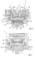
- FIG. 4 a device for producing a metal component using a casting-and-forming tool in a third embodiment in a longitudinal sectional view during casting,
- FIG. 5 the base part of the casting-and-forming tool of FIG. 4 in detail
- FIG. 6 a device for producing a metal component using a casting-and-forming tool in a further embodiment in a longitudinal sectional view during compressing
- FIG. 7 the device according to FIG. 6 during the partial post-compressing, with removed upper part and put on forging tool
- FIG. 8 a method for producing a metal component by a casting-and-forming tool
- FIG. 9 a state diagram (phase diagram) for a metal alloy for manufacturing a component according to the method of FIG. 8 .
- FIGS. 1 to 9 are described in the following together.
- a device 2 is shown for producing a metal component in a first embodiment
- a modified second embodiment is shown in FIGS. 5 and 6
- FIGS. 7 and 8 show a corresponding method for producing and, respectively, a state diagram (phase diagram) of a metal alloy used for the production.
- base part 5 and upper part 6 and casting-and-forming tool 4 are selected, as this tool is used for method steps which differ from each other.
- cast, casting mold, die, forming parts, lower mold, upper mold, base can be assigned to the casting-and-forming tool and its essential components.
- the device 2 comprises a filling-and-dosing unit 3 with a dosing container 31 as well as a casting-and-forming tool 4 with a base part 5 and an upper part 6 .
- a heating or melting device (not shown) can be arranged in front of the dosing unit 3 , which serves for dosing and filling of liquid metal into the forming tool 4 .
- the metal melt is fed from the melting device via the feed channel 7 to the dosing container 31 .
- FIG. 1 shows the dosing container 31 filled with a melt 9 of liquid metal.
- the dosing container 31 is formed funnel-shaped and has at its lower end a feed pipe 10 with an outlet opening 11 .
- An outlet valve 12 is provided in the dosing container 31 , for selectively opening or closing the feed pipe 10 as necessary, so that optionally melt can flow from the dosing container into the casting-and-forming tool 4 arranged below or the flow can be interrupted.
- a control sensor 13 is provided, which is in operative connection with a control unit for controlling the outlet valve 12 .
- the outlet valve 12 and the outlet opening 11 can be manufactured from ceramics or triamet.
- a fill level control unit 14 is provided in the dosing container 31 , which can determine a signal representing the filling level, and transmit said signal to the control unit.
- the liquid metal amount can thus be measured during or before the filling.
- a temperature sensor 15 is provided which is configured to determine a signal representing the temperature of the metal, wherein said temperature signal is also processed by the control unit.
- the filling temperature in the container 31 is ideally above the temperature that is necessary during the casting.
- the device 2 comprises an inert gas unit 16 , with which an inert gas can be fed via a feed pipe 17 into the dosing container 3 .
- an inert gas unit 16 By producing an inert gas atmosphere in the dosing container 3 , the formation of an undesired oxide layer is prevented. Carrying out the process in an inert gas atmosphere is optional and can be used depending on the alloy.
- the dosing container 3 is swingingly attached to a stationary component 18 by a swinging mechanism 19 , which for example can comprise one or more spring members.
- the casting-and-forming tool 4 into which the melt can flow when the outlet valve 12 is opened, is arranged below the device 3 .
- a filter 20 which delays the flow of the melt and causes a constant flow behavior into the base part 5 , is arranged at the outlet opening 11 of the dosing container 3 .
- the filter which can also be designated as an in-flow damper, can comprise a wire mesh made from stainless steel.
- the upper part 6 is positioned on the base part 5 , wherein the casting tool may not yet be completely closed before casting.
- a mold cavity 21 is formed between the parts 5 , 6 of the casting-and-forming tool 4 into which cavity the melt can flow and fill the same.
- the casting-and-forming tool 4 is formed such that an approximately pot-shaped cavity is enclosed.
- the base part 6 has a base portion 22 with a central projection 23 that is arranged in the area of the outlet opening 11 , as well as a circumferentially extending casing portion 24 .
- the upper part 6 which also can be designated as upper mold, comprises a cone-shaped portion 25 , a flange portion 26 connected to an upper end of the cone-shaped portion, as well as a circumferentially extending casing portion 27 that laterally surrounds the base part 5 .
- the inner faces or contours of both tool parts 5 , 6 are formed free of undercuts, so that an axial removal of the solidified component 8 is possible.
- a positioning mechanism e.g., including the member 28 , is arranged between the upper part 5 and the base part 6 for holding said tool parts in a defined position, respectively at a defined distance relative to each other during the casting.
- the positioning member 28 is formed as an annular member, which is arranged between a base member 29 and the base part 6 .
- the base member 29 is formed annularly or frame-like with a central opening 30 . It serves as a support for the casting-and-forming tool 4 , wherein the base part 5 is supported downwards on an edge encompassing the opening 30 , and wherein the upper part 6 is supported downwards via the annular body 28 radially outside of the base part 5 .
- the device 2 comprises a force application mechanism 32 for moving the base part 5 relative to the upper part 6 .
- the force application mechanism 32 which also can be designated as a stroke- or press mechanism, comprises a stroke member 33 , which is vertically movable relative to the base member 29 , and a support member 34 , which is supported via elastic and/or dampening bearing means 35 against the stroke member 33 .
- the stroke member 33 and the support member 34 respectively, pass through the through opening 30 of the base member 29 . By lifting the stroke member 33 , the support member 34 and the base part 5 supported thereon are loaded vertically upwards.
- the base part 5 approaches the upper part 6 , which is held stationary, wherein the gap 36 formed between the two parts 5 , 6 of the casting-and-forming tool 4 is at least partly closed.
- the component arranged therebetween can be compacted so that a fine-grained, free-of-pores structure is produced with a high strength. Vibrations can be introduced into the casting-and-forming tool 4 via a vibration mechanism 37 , which is arranged on the base part 5 and only shown schematically.
- the upper part 6 comprises through openings 38 , 39 by means of which a duct 40 of the inert gas unit and a suction unit 41 are connected.
- the base part 5 which is shown as a detail in FIG. 2 , is formed integrally.
- the undercut-free shape of the base part is visible, which provides for an axial removal of the workpiece after complete solidification.
- the base part 5 is formed rotation-symmetrically.
- FIG. 3 shows a device according to a modified second embodiment.
- This second embodiment corresponds to a large extent to the embodiment of FIG. 1 , so that concerning the common features the above description is referred to.
- the same or one another corresponding components are provided with the same reference numerals as in FIG. 1 .
- a cooling unit 60 is provided around the feed pipe 10 on the inner wall portion of the upper part 6 .
- a reservoir 61 is provided at the base part 5 , into which the metal alloy can flow.
- the reservoir 61 is enclosed by an insulating or heating device 51 , which holds the metal on a defined temperature or within a specific temperature range, respectively.
- the reservoir 61 is attached at a central portion of the base part 5 and extends vertically downwards.
- a controllable piston 62 is provided at the lower end of the reservoir 61 .
- the operating mode of the present embodiment is as follows.
- the melt 9 is cooled during the discharge, wherein the discharge velocity is configured such that the liquid metal alloy is transferred into a semi-solid-state by the cooling unit 60 .
- a semi-solid state means a state, in which the temperature of the alloy is around or approximately below the liquidus temperature TL.
- the reservoir 61 which can also be referred to as collecting vessel, the alloy is held in or slightly above the semi-solid-state, which means at or slightly above the liquidus temperature TL. Depending on the metal alloy, this state has to be adjusted in the range of few degrees of temperature.
- the inlet is closed and the piston 62 presses the alloy in the semi-solid state into the casting-and-forming tool 4 .
- the tool parts 5 , 6 of the casting-and-forming tool can be adjusted to temperatures that are at least 10% of the solidus temperature TS below the solidus temperature.
- the step of compressing of the component is carried out in the casting-and-forming tool 4 , and optionally the partial post-compression.
- FIG. 3 corresponds to that of FIGS. 1 and 2 , so that to that extent reference is made to the above description.
- FIGS. 4 and 5 show a device 2 according to a further embodiment. This largely corresponds to the embodiment of FIG. 1 , so that concerning the common features reference is made to the above description. In this case the same or one another corresponding components are provided with the same reference numerals as in FIG. 1 .
- a first difference compared to the embodiment of FIG. 1 is that the casting is carried out while the upper part 6 is removed from the base part 5 and is held at a distance thereto. Only after the filling of the melt is the upper part 6 then put onto the base part 5 , which is approached up to a defined distance and the process is continued as described in connection with FIG. 1 .
- the base part 5 is constructed from two parts, made up from a base portion 22 (base body) and a casing portion 24 (casing body).
- the base portion 22 and the casing portion 24 have complementary conical abutment faces 42 , 43 for centering and supporting the two bodies relative to each other.
- a radial gap 44 is formed in the assembled condition.
- An annular groove 45 is provided in an outer circumferential face of the annular casing portion 24 , which can be engaged by locking means 46 to fix the casing portion 24 relative to the base member 29 .
- the base member 29 is formed pot-like in the present case with a disc portion and a cylindrical portion.
- the positioning mechanism 28 which can also be referred to as positioning or side member, is interposed radially between the base member 29 and the base part 5 .
- the locking means 46 penetrate through the positioning member 28 and are supported in the annular portion of the base member 29 .
- the embodiment of FIGS. 4 and 5 correspond in design and operating mode to that of FIGS. 1 and 2 , so that concerning these reference is made to the above description.
- FIG. 6 shows a device in another embodiment. This embodiment largely corresponds to the embodiment of FIG. 1 , so that concerning the common features reference is made to the above description. In this case the same or one another corresponding components are provided with the same reference numerals as in FIGS. 1 and 2 .
- a difference in relation to the embodiment of FIG. 1 is that the casing portion 27 of the upper part 6 and the positioning member 28 have respectively at their inner faces cooling units 47 , 48 , facing the base part 5 .
- the cooling units 47 , 48 can be formed as cooling ribs or cooling channels, through which a cooling fluid can flow.
- the base portion 22 of the base part 4 is cooled in the present embodiment.
- a plate-like intermediate member 49 is arranged between the support member 34 and the base portion 22 , which has a cooling device 50 in form of cooling ribs or cooling channels at an upper side thereof, facing the base portion 22 .
- the vibration mechanism 37 is arranged between the intermediate member 49 and the support member 34 . Heat of the base part 5 of the casting-and-forming tool 4 can be discharged through the cooling units 47 , 48 , 50 , so that the component solidifies quicker.
- the device 2 of FIG. 6 is shown during and/or after the step of compressing (S 30 ).
- the base part 5 is lifted off by means of the force application mechanism 32 from the stationary base member 29 , which is formed in the present case as a support frame with a base and casing portion.
- the base part 5 is lifted up to the upper part 6 , so that the gap 36 is closed and the solidifying component is compressed.
- the through openings 38 , 39 are closed, so that the solidifying or already solidified material is not pressed out of the mold cavity.
- closing cylinders 52 are provided, which enter the through openings 38 , 39 and the inlet opening 53 and produce a counter pressure on the upper part 6 .
- first and second conveying rollers 55 , 56 are provided for vertically and horizontally guiding the lower support frame 29 and for moving said frame linearly in the advance direction.
- FIG. 7 shows the device of FIG. 6 in a following process step S 40 .
- the force application mechanism 32 is only shown schematically here. It is visible, that the upper support frame 54 , the closing cylinders 52 and the upper part 6 have been removed from the remaining assembly.
- a forging tool 57 is now moved into the component. Partial areas of the component are post-compressed by the forging tool 57 , which leads to especially high strengths in these partial areas.
- the forging tool 57 has an annular portion with an annular forging face 58 , which axially acts on the component so as to compress and plastically deform it.
- the forging tool 57 which can also be designated as a die, is attached and axially supported on a holder 58 .
- the embodiment corresponds in layout and operating mode to that of FIG. 6 , so that concerning this reference is made to the above description.
- FIG. 8 a method for producing a metal component is shown as a flow chart with the method steps S 10 to S 50 .
- a forgeable alloy can be used for the process, to achieve a microstructure with high strength.
- a melt of a metal alloy is discharged into the casting-and-forming tool 4 at a first pressure (P1), wherein the filling of the whole amount of melt is carried out non-pressurized, i.e., at atmospheric pressure.
- the melt is filled from above from the dosing container 31 into the casting-and-forming tool 4 .
- vibrations can be introduced into the latter.
- the outlet of the dosing container 31 is controlled by cooling and adjusting the discharge velocity such that the liquid metal is transferred into a semi-solid state.
- the filling-and-dosing unit 3 and the casting-and-forming tool 4 are separated from each other and the vibration mechanism 37 is switched off.
- the casting-and-forming tool 4 can be moved on a conveying unit to the next process station.
- step S 20 pressure is applied to the metal alloy arranged in the mold cavity.
- a pressure P2 is built-up between the base part 5 and the upper part 6 , is the pressure P2 being greater than the atmospheric pressure, i.e., the first pressure P1.
- This pressure P2 can, for example, be produced by the dead weight of the upper part 6 .
- All openings of the casting-and-forming tool 4 have to be closed before force application, so that no material is unintendedly pressed out of the tool.
- the step of applying pressure of the melt can be carried out in a component-shell-temperature range T2 of around the liquidus line TL up to above the solidus line TS of the metal alloy, this means TS ⁇ T2 ⁇ TL.
- the material is still liquid. At the end of the step of applying pressure the material is at least partially in a dough-like state.
- the advancing process of solidification of the material during the method step 20 can be influenced, as required, by corresponding heating of the base part 5 and/or the upper part 6 .
- the base part 5 can be heated to a higher temperature than the upper part 6 , at which upper part a solidification of the metal alloy then takes place more quickly.
- the parts 5 , 6 of the casting-and-forming tool 4 can have one or more cooling circuits, wherein at least one temperature sensor is assigned to each cooling circuit.
- the cooling can be carried out in a water-air mixture in a ratio according to requirements to ensure a specific solidification process in the component.
- a compression of said component is carried out in the next method step S 30 .
- the step of compressing is carried out by relative moving of the base part 5 towards the upper part 6 such that a third pressure P3 is generated, which is larger than the second pressure P2 in the method step S 20 .
- the compressing takes place by pressing the lower part 5 in a direction of the upper part 6 with high forces.
- the compressing may start only when the metal alloy is at least mostly solidified, i.e., is in the semi-solid state.
- the compressing can be carried out at a component-shell-temperature T3, which is lower than the component-shell-temperature T2 of the metal alloy during the method step of applying pressure S 20 .
- a component-shell-temperature T3 which is lower than the component-shell-temperature T2 of the metal alloy during the method step of applying pressure S 20 .
- half of the solidus temperature TS of the metal alloy can be used; this means T2>T3>0.5TS.
- the end of the forming process is defined by reaching an end position of the relative movement of the upper part towards the base part and by achieving a predetermined temperature.
- the component only experiences a comparably low degree of deformation of less than 15%, especially less than 10%, or less than 5%. Pores in the component are closed during compressing, so that the microstructure of the workpiece is improved.
- a flow forming of partial areas of the component can be carried out in a further method step S 50 .
- flow forming outer or inner contours with undercuts can be produced in the deformed component.
- cast blanks can be produced in several steps in the same base part, by casting (S 10 ), following applying pressure (S 20 ), following compression/deformation (S 30 ) and optional partial material post-compression (S 40 ).
- the pressure application (S 20 ) takes place above the solidus temperature (liquid up to doughy state) of the respectively used alloy.
- FIG. 9 shows a state diagram (phase diagram) for a metal alloy for manufacturing a component according to the method or with the device according to the invention.
- the ratio of the amount of a metal alloy (WL) is stated, which comprises XA % of a metal A and XB % of a metal B.
- T the temperature
- the temperature range T2 for the step of pressure application which is preferably below the liquidus temperature (TL) and above the solidus temperature TS (TL>T2>TS), is horizontally hatched in FIG. 9 .
- a remaining degree of deformation of less than 15% remains for the following compressing (S 30 ).
- the step of compressing (S 30 ) takes place especially in a temperature range T3 between the temperature T2 and half the solidus temperature 0.5TS (T2>T3>0.5 TS). This range is hatched from left top to right bottom in FIG. 9 .
- a partial metal post-compressing takes place at stress-exposed component regions, which can be achieved by means of introducing a die from above. This especially takes place at a temperature T4 below the temperature T3, respectively below 90% of the solidus temperature (T3>T4 and/or T4 ⁇ 0.9 TS). This temperature range is shown vertically hatched in FIG. 9 .
- the method offers more degrees of freedom concerning the design and shape as known casting methods, as for producing raw cast parts casting specific cross-sections are not necessary to the extent necessary there.
- the whole manufacturing process takes place in a simple base part 5 with the optional use of a die 57 .
- the upper part 6 and, where applicable, one or more side parts which may be used optionally, have at the beginning of the flow process distinctly lower temperatures (temperature difference of up to 50% of the solidus temperature) than the base part 5 .
- a microstructure with kneading texture with better mechanical properties can be achieved from a quickly cooling casting microstructure.
Applications Claiming Priority (3)
| Application Number | Priority Date | Filing Date | Title |
|---|---|---|---|
| EP13184634 | 2013-09-16 | ||
| EP13184634.7A EP2848333B1 (de) | 2013-09-16 | 2013-09-16 | Verfahren und Vorrichtung zur Herstellung eines metallischen Bauteils mittels eines Gieß- und Formwerkzeugs |
| EP13184634.7 | 2013-09-16 |
Publications (2)
| Publication Number | Publication Date |
|---|---|
| US20150074983A1 US20150074983A1 (en) | 2015-03-19 |
| US10022780B2 true US10022780B2 (en) | 2018-07-17 |
Family
ID=49226020
Family Applications (1)
| Application Number | Title | Priority Date | Filing Date |
|---|---|---|---|
| US14/484,695 Active 2035-03-21 US10022780B2 (en) | 2013-09-16 | 2014-09-12 | Producing a metal component with a casting-and-forming tool |
Country Status (12)
| Country | Link |
|---|---|
| US (1) | US10022780B2 (ko) |
| EP (1) | EP2848333B1 (ko) |
| JP (1) | JP6756459B2 (ko) |
| KR (1) | KR102232632B1 (ko) |
| CN (1) | CN104439158B (ko) |
| AU (1) | AU2014218476B2 (ko) |
| BR (1) | BR102014022376A2 (ko) |
| CA (1) | CA2863313C (ko) |
| IN (1) | IN2014MU02749A (ko) |
| MX (1) | MX361898B (ko) |
| RU (1) | RU2593054C2 (ko) |
| TW (1) | TWI555595B (ko) |
Cited By (1)
| Publication number | Priority date | Publication date | Assignee | Title |
|---|---|---|---|---|
| US10801089B2 (en) * | 2015-11-02 | 2020-10-13 | Mubea Performance Wheels Gmbh | Light metal cast component |
Families Citing this family (29)
| Publication number | Priority date | Publication date | Assignee | Title |
|---|---|---|---|---|
| CN106493337B (zh) * | 2016-11-18 | 2019-09-03 | 福州鸿基自动化设备有限公司 | 自吸式给汤机 |
| CN106345957A (zh) * | 2016-11-29 | 2017-01-25 | 洛阳秦汉精工股份有限公司 | 一种半固态模锻模具装置 |
| CN106378407A (zh) * | 2016-11-29 | 2017-02-08 | 洛阳秦汉精工股份有限公司 | 一种复合半固态模锻模具装置 |
| PL3330020T3 (pl) | 2016-12-05 | 2022-02-07 | Mubea Performance Wheels Gmbh | Urządzenie odlewnicze i sposób odlewania |
| RU2764620C2 (ru) * | 2018-07-10 | 2022-01-18 | Общество С Ограниченной Ответственностью "Бетарут" | Способ и устройство жидкой ковки двойного действия |
| CN108817350A (zh) * | 2018-07-13 | 2018-11-16 | 安徽思源三轻智能制造有限公司 | 液态模锻机的进料机构 |
| CN108672690A (zh) * | 2018-08-30 | 2018-10-19 | 福建亚亨机械股份有限公司 | 铅成型铅丝定量加铅铅锅 |
| RU2746073C1 (ru) * | 2019-12-20 | 2021-04-06 | Анвар Юсуфович Боташев | Способ литья под давлением |
| DE102020100702A1 (de) | 2020-01-14 | 2021-07-15 | Audi Aktiengesellschaft | Verfahren zum Herstellen einer Kraftwagenfelge aus Aluminium oder einer Aluminiumlegierung für ein Rad eines Kraftfahrzeugs sowie entsprechende Vorrichtung zum Herstellen einer Kraftwagenfelge |
| DE102020100699A1 (de) * | 2020-01-14 | 2021-07-15 | Audi Aktiengesellschaft | Verfahren zum Herstellen einer Kraftwagenfelge aus Aluminium oder einer Aluminiumlegierung für ein Rad eines Kraftfahrzeugs sowie entsprechende Kraftwagenfelge |
| DE102020100705A1 (de) * | 2020-01-14 | 2021-07-15 | Audi Aktiengesellschaft | Verfahren zum Herstellen einer Kraftwagenfelge aus Aluminium oder einer Aluminiumlegierung für ein Rad eines Kraftfahrzeugs sowie entsprechende Vorrichtung zum Herstellen einer Kraftwagenfelge |
| DE102020100701A1 (de) * | 2020-01-14 | 2021-07-15 | Audi Aktiengesellschaft | Verfahren zum Herstellen einer Kraftwagenfelge aus Aluminium oder einer Aluminiumlegierung für ein Rad eines Kraftfahrzeugs sowie entsprechende Kraftwagenfelge |
| DE102020100691A1 (de) * | 2020-01-14 | 2021-07-15 | Audi Aktiengesellschaft | Verfahren zum Herstellen einer Kraftwagenfelge aus Aluminium oder einer Aluminiumlegierung für ein Rad eines Kraftfahrzeugs, Vorrichtung zum Herstellen einer Kraftwagenfelge sowie Verfahren zum Herstellen von mehreren Kraftwagenfelgen |
| DE102020100697A1 (de) * | 2020-01-14 | 2021-07-15 | Audi Aktiengesellschaft | Verfahren zum Herstellen einer Kraftwagenfelge aus Aluminium oder einer Aluminiumlegierung für ein Rad eines Kraftfahrzeugs sowie entsprechende Kraftwagenfelge |
| DE102020100704A1 (de) * | 2020-01-14 | 2021-07-15 | Audi Aktiengesellschaft | Verfahren zum Herstellen einer Kraftwagenfelge aus Aluminium oder einer Aluminiumlegierung für ein Rad eines Kraftfahrzeugs sowie Vorrichtung zum Herstellen einer Kraftwagenfelge |
| DE102020100703A1 (de) * | 2020-01-14 | 2021-07-15 | Audi Aktiengesellschaft | Verfahren zum Herstellen einer Kraftwagenfelge aus Aluminium oder einer Aluminiumlegierung für ein Rad eines Kraftfahrzeugs sowie entsprechende Kraftwagenfelge |
| DE102020100700A1 (de) * | 2020-01-14 | 2021-07-15 | Audi Aktiengesellschaft | Verfahren zum Herstellen einer Kraftwagenfelge aus Aluminium oder einer Aluminiumlegierung für ein Rad eines Kraftfahrzeugs sowie entsprechende Kraftwagenfelge |
| DE102020100693A1 (de) * | 2020-01-14 | 2021-07-15 | Audi Aktiengesellschaft | Verfahren zum Herstellen einer Kraftwagenfelge aus Aluminium oder einer Aluminiumlegierung für ein Rad eines Kraftfahrzeugs sowie entsprechende Kraftwagenfelge |
| DE102020100696A1 (de) * | 2020-01-14 | 2021-07-15 | Audi Aktiengesellschaft | Verfahren zum Herstellen einer Kraftwagenfelge aus Aluminium oder einer Aluminiumlegierung für ein Rad eines Kraftfahrzeugs sowie entsprechende Kraftwagenfelge |
| DE102020100689A1 (de) * | 2020-01-14 | 2021-07-15 | Audi Aktiengesellschaft | Verfahren zum Herstellen einer Kraftwagenfelge aus Aluminium oder einer Aluminiumlegierung für ein Rad eines Kraftfahrzeugs sowie Kraftwagenfelge |
| CN111186518A (zh) * | 2020-01-16 | 2020-05-22 | 济南慧成铸造有限公司 | 一种一体式车架及其制造方法 |
| RU2759369C1 (ru) * | 2020-11-19 | 2021-11-12 | Акционерное общество «Научно-производственная корпорация «Уралвагонзавод» имени Ф.Э. Дзержинского» | Способ контроля времени заполнения литейных форм и устройство для его осуществления |
| CN112453374A (zh) * | 2020-11-30 | 2021-03-09 | 中北大学 | 一种恒容式定量浇注方法 |
| CN112453373A (zh) * | 2020-11-30 | 2021-03-09 | 中北大学 | 一种恒容式定量浇注装置 |
| CN114160773B (zh) * | 2021-11-17 | 2024-01-30 | 浙江步阳汽轮有限公司 | 一种自动化低压铸造轮毂生产装置 |
| IT202100031076A1 (it) * | 2021-12-10 | 2023-06-10 | Paolo Zolesi | Metodo per fabbricare un pezzo in lega leggera tramite una colata di lega leggera fusa a bassa pressione e apparecchiatura per eseguire tale metodo |
| CN114433761B (zh) * | 2022-01-26 | 2023-09-15 | 太原理工大学 | 一种挤压成形带加强内筋的钛/铝复合筒形件及其成形工艺 |
| DE102022115993A1 (de) | 2022-06-28 | 2023-12-28 | Audi Aktiengesellschaft | Verfahren und Gießform zum Herstellen eines Rads für ein Kraftfahrzeug |
| TWI820882B (zh) * | 2022-08-29 | 2023-11-01 | 巧新科技工業股份有限公司 | 水平連續鑄造異型切片鑄料鍛造模具及其鍛造方法及水平連續鑄造異型鑄棒裝置 |
Citations (17)
| Publication number | Priority date | Publication date | Assignee | Title |
|---|---|---|---|---|
| FR2504424A1 (fr) | 1981-04-22 | 1982-10-29 | Amil Sa | Procede et dispositif perfectionnes de coulee par gravite avec pression additionnelle par verin |
| EP0338419A1 (de) | 1988-04-16 | 1989-10-25 | Wehag Leichtmetall Gmbh | Giess-Schmiede-Verfahren |
| EP0423447A2 (en) | 1989-08-24 | 1991-04-24 | TVA HOLDING S.p.A. | Process and apparatus for the controlled-pressure casting of molten metals, particularly light alloys of aluminum and magnesium |
| US5301739A (en) * | 1992-06-30 | 1994-04-12 | Cook Arnold J | Method for casting and densification |
| US5647426A (en) * | 1993-10-07 | 1997-07-15 | Hayes Wheels International, Inc. | Method and apparatus for controlled directional solidification of a wheel casting |
| US5722165A (en) * | 1995-10-27 | 1998-03-03 | Topy Kogyo Kabushiki Kaisha | Method of producing a cast wheel |
| US5729883A (en) | 1994-09-30 | 1998-03-24 | Nissan Motor Co., Ltd. | Method of producing a forging |
| CN1572397A (zh) | 2003-06-23 | 2005-02-02 | 金�一 | 用于汽车的铝车轮铸造装置 |
| JP2005074461A (ja) | 2003-08-29 | 2005-03-24 | Nisshin Seisakusho:Kk | 成形品の製造方法 |
| TW200726544A (en) | 2006-01-13 | 2007-07-16 | Taiwan Advanced Materials Technologies Corp | Vertical type vacuum continuous casting equipment |
| CN200954537Y (zh) | 2006-04-27 | 2007-10-03 | 葛明 | 立式全自动转子压铸机 |
| DE102006036369A1 (de) | 2006-08-02 | 2008-02-14 | Kahn, Friedhelm, Prof. Dr. Ing. | Verfahren und Vorrichtung zur Herstellung von Bauteilen durch integriertes Schmelzen, Gießen und Umformen |
| US20080041552A1 (en) * | 2006-08-18 | 2008-02-21 | Dubay Richard L | Single-piece cooling blocks for casting and molding |
| CN101468378A (zh) | 2008-06-21 | 2009-07-01 | 冯福贵 | 铝合金炒锅液态模锻锻模及铝合金炒锅制作工艺 |
| CN101787472A (zh) | 2010-03-18 | 2010-07-28 | 上海交通大学 | 耐热锻压镁稀土合金及其制备方法 |
| DE102011119643A1 (de) | 2011-11-28 | 2013-05-29 | UNIWHEELS Management (Switzerland) AG | Verfahren zur Herstellung eines Rohlings oder Sternrohlings für ein Fahrzeugrad |
| US20160214429A1 (en) * | 2013-09-05 | 2016-07-28 | GM Global Technology Operations LLC | Methods and apparatus to produce high performance axisymmetric components |
Family Cites Families (6)
| Publication number | Priority date | Publication date | Assignee | Title |
|---|---|---|---|---|
| JPS6046856A (ja) * | 1983-08-24 | 1985-03-13 | Honda Motor Co Ltd | 加圧鋳造法 |
| SU1219242A1 (ru) * | 1984-10-31 | 1986-03-23 | Днепропетровский Ордена Трудового Красного Знамени Металлургический Институт Им.Л.И.Брежнева | Совмещенный способ лить и обработки давлением |
| SU1237308A1 (ru) * | 1984-12-06 | 1986-06-15 | Пермский политехнический институт | Пресс-форма дл лить с кристаллизацией под давлением |
| JP2518981B2 (ja) * | 1991-08-22 | 1996-07-31 | 株式会社レオテック | 半凝固金属の成形方法 |
| JP2001232455A (ja) * | 2000-12-28 | 2001-08-28 | Bbs Motorsport & Engineering Gmbh | 溶融金属を鋳込むための方法と装置 |
| KR20090079748A (ko) * | 2008-01-17 | 2009-07-22 | 오일광 | 프레스장치를 이용한 다단가압식 주·단조 금형유닛 및 그공법 |
-
2013
- 2013-09-16 EP EP13184634.7A patent/EP2848333B1/de active Active
-
2014
- 2014-08-27 IN IN2749MU2014 patent/IN2014MU02749A/en unknown
- 2014-09-01 AU AU2014218476A patent/AU2014218476B2/en not_active Ceased
- 2014-09-10 MX MX2014010868A patent/MX361898B/es active IP Right Grant
- 2014-09-10 BR BR102014022376A patent/BR102014022376A2/pt not_active Application Discontinuation
- 2014-09-12 CA CA2863313A patent/CA2863313C/en not_active Expired - Fee Related
- 2014-09-12 US US14/484,695 patent/US10022780B2/en active Active
- 2014-09-15 RU RU2014137317/02A patent/RU2593054C2/ru not_active IP Right Cessation
- 2014-09-15 KR KR1020140121950A patent/KR102232632B1/ko active IP Right Grant
- 2014-09-16 JP JP2014188110A patent/JP6756459B2/ja active Active
- 2014-09-16 CN CN201410471288.0A patent/CN104439158B/zh active Active
- 2014-09-16 TW TW103131862A patent/TWI555595B/zh active
Patent Citations (19)
| Publication number | Priority date | Publication date | Assignee | Title |
|---|---|---|---|---|
| FR2504424A1 (fr) | 1981-04-22 | 1982-10-29 | Amil Sa | Procede et dispositif perfectionnes de coulee par gravite avec pression additionnelle par verin |
| EP0338419A1 (de) | 1988-04-16 | 1989-10-25 | Wehag Leichtmetall Gmbh | Giess-Schmiede-Verfahren |
| DE3812740A1 (de) | 1988-04-16 | 1989-10-26 | Wehag Leichtmetall Gmbh | Giess-schmiede-verfahren |
| EP0423447A2 (en) | 1989-08-24 | 1991-04-24 | TVA HOLDING S.p.A. | Process and apparatus for the controlled-pressure casting of molten metals, particularly light alloys of aluminum and magnesium |
| US5143141A (en) * | 1989-08-24 | 1992-09-01 | Tva Holding S.P.A. | Process and apparatus for the controlled-pressure casting of molten metals |
| US5301739A (en) * | 1992-06-30 | 1994-04-12 | Cook Arnold J | Method for casting and densification |
| US5647426A (en) * | 1993-10-07 | 1997-07-15 | Hayes Wheels International, Inc. | Method and apparatus for controlled directional solidification of a wheel casting |
| US5729883A (en) | 1994-09-30 | 1998-03-24 | Nissan Motor Co., Ltd. | Method of producing a forging |
| US5722165A (en) * | 1995-10-27 | 1998-03-03 | Topy Kogyo Kabushiki Kaisha | Method of producing a cast wheel |
| CN1572397A (zh) | 2003-06-23 | 2005-02-02 | 金�一 | 用于汽车的铝车轮铸造装置 |
| JP2005074461A (ja) | 2003-08-29 | 2005-03-24 | Nisshin Seisakusho:Kk | 成形品の製造方法 |
| TW200726544A (en) | 2006-01-13 | 2007-07-16 | Taiwan Advanced Materials Technologies Corp | Vertical type vacuum continuous casting equipment |
| CN200954537Y (zh) | 2006-04-27 | 2007-10-03 | 葛明 | 立式全自动转子压铸机 |
| DE102006036369A1 (de) | 2006-08-02 | 2008-02-14 | Kahn, Friedhelm, Prof. Dr. Ing. | Verfahren und Vorrichtung zur Herstellung von Bauteilen durch integriertes Schmelzen, Gießen und Umformen |
| US20080041552A1 (en) * | 2006-08-18 | 2008-02-21 | Dubay Richard L | Single-piece cooling blocks for casting and molding |
| CN101468378A (zh) | 2008-06-21 | 2009-07-01 | 冯福贵 | 铝合金炒锅液态模锻锻模及铝合金炒锅制作工艺 |
| CN101787472A (zh) | 2010-03-18 | 2010-07-28 | 上海交通大学 | 耐热锻压镁稀土合金及其制备方法 |
| DE102011119643A1 (de) | 2011-11-28 | 2013-05-29 | UNIWHEELS Management (Switzerland) AG | Verfahren zur Herstellung eines Rohlings oder Sternrohlings für ein Fahrzeugrad |
| US20160214429A1 (en) * | 2013-09-05 | 2016-07-28 | GM Global Technology Operations LLC | Methods and apparatus to produce high performance axisymmetric components |
Non-Patent Citations (1)
| Title |
|---|
| Translation of DE3812740 (cited in IDS), generated Sep. 26, 2016. * |
Cited By (1)
| Publication number | Priority date | Publication date | Assignee | Title |
|---|---|---|---|---|
| US10801089B2 (en) * | 2015-11-02 | 2020-10-13 | Mubea Performance Wheels Gmbh | Light metal cast component |
Also Published As
| Publication number | Publication date |
|---|---|
| CN104439158B (zh) | 2019-04-05 |
| JP6756459B2 (ja) | 2020-09-16 |
| JP2015057294A (ja) | 2015-03-26 |
| US20150074983A1 (en) | 2015-03-19 |
| KR102232632B1 (ko) | 2021-03-26 |
| AU2014218476A1 (en) | 2015-04-02 |
| RU2014137317A (ru) | 2016-04-10 |
| EP2848333B1 (de) | 2021-03-24 |
| CA2863313C (en) | 2017-01-03 |
| TWI555595B (zh) | 2016-11-01 |
| RU2593054C2 (ru) | 2016-07-27 |
| AU2014218476B2 (en) | 2016-04-28 |
| IN2014MU02749A (ko) | 2015-10-09 |
| MX2014010868A (es) | 2015-07-16 |
| MX361898B (es) | 2018-11-30 |
| BR102014022376A2 (pt) | 2015-09-15 |
| TW201524637A (zh) | 2015-07-01 |
| CA2863313A1 (en) | 2015-03-16 |
| CN104439158A (zh) | 2015-03-25 |
| EP2848333A1 (de) | 2015-03-18 |
| KR20150032196A (ko) | 2015-03-25 |
Similar Documents
| Publication | Publication Date | Title |
|---|---|---|
| US10022780B2 (en) | Producing a metal component with a casting-and-forming tool | |
| CN100389904C (zh) | 半固态模铸方法 | |
| US5575325A (en) | Semi-molten metal molding method and apparatus | |
| TWI801360B (zh) | 澆鑄裝置及澆鑄方法 | |
| JP5637287B2 (ja) | 熱間鍛造による鍛造装置 | |
| US8250897B2 (en) | High strength workpiece material and method and apparatus for producing the same | |
| EA031934B1 (ru) | Железнодорожное колесо, устройство и способ производства | |
| US6609286B2 (en) | Process for manufacturing a part of a metal matrix composite material | |
| RU2614490C2 (ru) | Способ и установка для производства формованных деталей из алюминиевого сплава для транспортных средств и бытовой техники | |
| JP2016215270A (ja) | 半凝固金属材料のプレス成形方法及びプレス成形装置 | |
| JP4325921B2 (ja) | 密閉鍛造方法及び密閉鍛造装置 | |
| CN115041636B (zh) | 镁合金轮毂的挤压铸造成型模具 | |
| CN100389902C (zh) | 形成金属基复合材料产品的方法 | |
| CN1596168A (zh) | 制造压力铸造件的方法及铸造装置 | |
| RU2233728C1 (ru) | Способ изготовления изделий с использованием жидкой штамповки и горячей деформации | |
| JPH02284755A (ja) | 軽金属成形品の製造方法 | |
| JP3297910B2 (ja) | 溶融金属を鋳込んで車両用のホイールを製造するための方法と装置 | |
| JPH0386363A (ja) | 溶湯鍛造方法 | |
| JP2000355206A (ja) | 自動車用サスペンション部材 | |
| Zhang et al. | Hydraulic extrusion forming for the case of compressor in air conditioner | |
| JPH07290224A (ja) | アルミニウム等の半溶融鍛造成形における材料注入方法 |
Legal Events
| Date | Code | Title | Description |
|---|---|---|---|
| AS | Assignment |
Owner name: MUBEA CARBO TECH GMBH, AUSTRIA Free format text: ASSIGNMENT OF ASSIGNORS INTEREST;ASSIGNOR:HUBAUER, WERNER;REEL/FRAME:034035/0581 Effective date: 20140912 |
|
| STCF | Information on status: patent grant |
Free format text: PATENTED CASE |
|
| MAFP | Maintenance fee payment |
Free format text: PAYMENT OF MAINTENANCE FEE, 4TH YEAR, LARGE ENTITY (ORIGINAL EVENT CODE: M1551); ENTITY STATUS OF PATENT OWNER: LARGE ENTITY Year of fee payment: 4 |