TWI779538B - A powder container to contain powder - Google Patents

A powder container to contain powder Download PDF

Info

Publication number
TWI779538B
TWI779538B TW110111208A TW110111208A TWI779538B TW I779538 B TWI779538 B TW I779538B TW 110111208 A TW110111208 A TW 110111208A TW 110111208 A TW110111208 A TW 110111208A TW I779538 B TWI779538 B TW I779538B
Authority
TW
Taiwan
Prior art keywords
container
toner
nozzle
powder
opening
Prior art date
Application number
TW110111208A
Other languages
Chinese (zh)
Other versions
TW202129441A (en
Inventor
細川浩
加藤俊次
田牧真二
池口弘
寺澤誠司
山部順司
三石香織
友高利英
渡邊常弘
菊地賢治
Original Assignee
日商理光股份有限公司
Priority date (The priority date is an assumption and is not a legal conclusion. Google has not performed a legal analysis and makes no representation as to the accuracy of the date listed.)
Filing date
Publication date
Priority claimed from JP2011258356A external-priority patent/JP5822129B2/en
Priority claimed from JP2011258355A external-priority patent/JP5822128B2/en
Priority claimed from JP2012256921A external-priority patent/JP5435380B1/en
Application filed by 日商理光股份有限公司 filed Critical 日商理光股份有限公司
Publication of TW202129441A publication Critical patent/TW202129441A/en
Application granted granted Critical
Publication of TWI779538B publication Critical patent/TWI779538B/en

Links

Images

Classifications

    • GPHYSICS
    • G03PHOTOGRAPHY; CINEMATOGRAPHY; ANALOGOUS TECHNIQUES USING WAVES OTHER THAN OPTICAL WAVES; ELECTROGRAPHY; HOLOGRAPHY
    • G03GELECTROGRAPHY; ELECTROPHOTOGRAPHY; MAGNETOGRAPHY
    • G03G15/00Apparatus for electrographic processes using a charge pattern
    • G03G15/06Apparatus for electrographic processes using a charge pattern for developing
    • G03G15/08Apparatus for electrographic processes using a charge pattern for developing using a solid developer, e.g. powder developer
    • G03G15/0822Arrangements for preparing, mixing, supplying or dispensing developer
    • G03G15/0863Arrangements for preparing, mixing, supplying or dispensing developer provided with identifying means or means for storing process- or use parameters, e.g. an electronic memory
    • GPHYSICS
    • G03PHOTOGRAPHY; CINEMATOGRAPHY; ANALOGOUS TECHNIQUES USING WAVES OTHER THAN OPTICAL WAVES; ELECTROGRAPHY; HOLOGRAPHY
    • G03GELECTROGRAPHY; ELECTROPHOTOGRAPHY; MAGNETOGRAPHY
    • G03G15/00Apparatus for electrographic processes using a charge pattern
    • G03G15/06Apparatus for electrographic processes using a charge pattern for developing
    • G03G15/08Apparatus for electrographic processes using a charge pattern for developing using a solid developer, e.g. powder developer
    • G03G15/0822Arrangements for preparing, mixing, supplying or dispensing developer
    • G03G15/0865Arrangements for supplying new developer
    • G03G15/0867Arrangements for supplying new developer cylindrical developer cartridges, e.g. toner bottles for the developer replenishing opening
    • G03G15/087Developer cartridges having a longitudinal rotational axis, around which at least one part is rotated when mounting or using the cartridge
    • G03G15/0872Developer cartridges having a longitudinal rotational axis, around which at least one part is rotated when mounting or using the cartridge the developer cartridges being generally horizontally mounted parallel to its longitudinal rotational axis
    • GPHYSICS
    • G03PHOTOGRAPHY; CINEMATOGRAPHY; ANALOGOUS TECHNIQUES USING WAVES OTHER THAN OPTICAL WAVES; ELECTROGRAPHY; HOLOGRAPHY
    • G03GELECTROGRAPHY; ELECTROPHOTOGRAPHY; MAGNETOGRAPHY
    • G03G15/00Apparatus for electrographic processes using a charge pattern
    • G03G15/06Apparatus for electrographic processes using a charge pattern for developing
    • G03G15/08Apparatus for electrographic processes using a charge pattern for developing using a solid developer, e.g. powder developer
    • G03G15/0822Arrangements for preparing, mixing, supplying or dispensing developer
    • G03G15/0877Arrangements for metering and dispensing developer from a developer cartridge into the development unit
    • G03G15/0881Sealing of developer cartridges
    • G03G15/0886Sealing of developer cartridges by mechanical means, e.g. shutter, plug
    • GPHYSICS
    • G03PHOTOGRAPHY; CINEMATOGRAPHY; ANALOGOUS TECHNIQUES USING WAVES OTHER THAN OPTICAL WAVES; ELECTROGRAPHY; HOLOGRAPHY
    • G03GELECTROGRAPHY; ELECTROPHOTOGRAPHY; MAGNETOGRAPHY
    • G03G2215/00Apparatus for electrophotographic processes
    • G03G2215/06Developing structures, details
    • G03G2215/066Toner cartridge or other attachable and detachable container for supplying developer material to replace the used material
    • G03G2215/0663Toner cartridge or other attachable and detachable container for supplying developer material to replace the used material having a longitudinal rotational axis, around which at least one part is rotated when mounting or using the cartridge
    • G03G2215/0665Generally horizontally mounting of said toner cartridge parallel to its longitudinal rotational axis
    • G03G2215/0668Toner discharging opening at one axial end
    • GPHYSICS
    • G03PHOTOGRAPHY; CINEMATOGRAPHY; ANALOGOUS TECHNIQUES USING WAVES OTHER THAN OPTICAL WAVES; ELECTROGRAPHY; HOLOGRAPHY
    • G03GELECTROGRAPHY; ELECTROPHOTOGRAPHY; MAGNETOGRAPHY
    • G03G2215/00Apparatus for electrophotographic processes
    • G03G2215/06Developing structures, details
    • G03G2215/066Toner cartridge or other attachable and detachable container for supplying developer material to replace the used material
    • G03G2215/0695Toner cartridge or other attachable and detachable container for supplying developer material to replace the used material using identification means or means for storing process or use parameters
    • G03G2215/0697Toner cartridge or other attachable and detachable container for supplying developer material to replace the used material using identification means or means for storing process or use parameters being an electronically readable memory

Abstract

A powder container to contain powder, comprising: a nozzle receiving opening at one side of the powder container in a longitudinal direction of the powder container; a scoop, at the one side, to scoop up the powder, when the scoop rotates about a longitudinal axis of the powder container, from a first position within the powder container and drops the powder from a second position within the powder container which is higher than the first position; a shutter, at the one side, to open and close the nozzle receiving opening; a region, at the one side, which permits the shutter to move toward an other side of the powder container, which is opposite side of the one side in the longitudinal direction, to open the shutter; a protrusion adjacent to the region, at the one side, which protrudes away from the nozzle receiving opening toward the other side.

Description

一種容納粉末的粉末容器 A powder container for containing powder

本發明涉及一種用於容納如碳粉等粉末的粉末容器,以及一種將粉末從粉末容器傳送到傳送目的地的影像形成設備。 The present invention relates to a powder container for containing powder such as toner, and an image forming apparatus for transferring the powder from the powder container to a transfer destination.

在使用電子照像處理的影像形成設備中,如影印機、印表機或傳真機等,在光感受器上形成的潛像係由顯影裝置提供的碳粉所顯影。由於在整個潛像的顯影期間會消耗碳粉,因此有必要對顯影裝置再補給碳粉。因此,作為設置在設備主體中的粉末供應裝置的碳粉再補給裝置,將碳粉從作為粉末容器的碳粉容器傳送到顯影裝置,使得該顯影裝置可以進行碳粉的再補給。如上所述之可以再填充碳粉的顯影裝置能夠使顯影得已持續。此外,碳粉容器可拆卸地連接於碳粉再補給裝置。如果容納在碳粉容器中的碳粉被使用完,則該碳粉容器就由容納有新碳粉的一個碳粉容器所替換。 In image forming equipment using electrophotographic processing, such as photocopiers, printers, or facsimile machines, the latent image formed on the photoreceptor is developed with toner supplied from a developing device. Since toner is consumed throughout the development of the latent image, it is necessary to resupply the developing device with toner. Therefore, the toner resupply means as the powder supply means provided in the apparatus main body conveys the toner from the toner container as the powder container to the developing means so that the developing means can perform toner resupply. The refillable toner developing device as described above enables continuous development. In addition, the toner container is detachably connected to the toner resupply device. If the toner contained in the toner container is used up, the toner container is replaced by a toner container containing new toner.

關於可拆卸地連接於碳粉再補給裝置的碳粉容器,其中一習知的碳粉容器具有在碳粉儲存構件的圓柱形內表面上形成的螺旋肋條,所述碳粉儲存構件係用於容納碳粉(請看專利文件1:日本專利申請公開第2003-241496號;專利文件2:日本專利申請公開第2005-221825號;專利文件3:日本專利申請公開第4342958號;專利文件4:日本專利申請公開第2002-202656號;以及專利文件5:日本專利申請公開第2003-233247號)。在這種碳粉容器中,碳粉容器連接到碳粉再補給裝置的同時,碳粉儲存構件也被旋轉,使得所儲存的碳粉從在旋轉軸方向上的第一端部被傳送到另外一個端部。其後,碳粉經由在碳粉儲存構件的另外一個端部上設置的開口被排放到碳粉再補給裝置的主體。 Regarding the toner container detachably connected to the toner resupply device, a known toner container has spiral ribs formed on a cylindrical inner surface of a toner storage member for Hold carbon powder (see patent document 1: Japanese Patent Application Publication No. 2003-241496; Patent Document 2: Japanese Patent Application Publication No. 2005-221825; Patent Document 3: Japanese Patent Application Publication No. 4342958; Patent Document 4: Japanese Patent Application Publication No. 2002-202656; and Patent Document 5: Japanese Patent Application Publication No. 2003-233247). In this toner container, while the toner container is connected to the toner resupply device, the toner storage member is also rotated so that the stored toner is transferred from the first end in the direction of the rotation axis to the other end. one end. Thereafter, the toner is discharged to the main body of the toner resupply device through the opening provided on the other end portion of the toner storage member.

關於通過旋轉碳粉儲存構件將儲存在其中的碳粉從一個端部 傳送到另外一個端部的碳粉容器,專利文件6(日本專利申請公開第2009-276659號)描述了一種碳粉容器,其中,被固定到碳粉再補給裝置的傳送噴嘴經由碳粉儲存構件的另外一個端部上的開口插入。具體而言,碳粉接收開口以插入方向形成在插入到碳粉容器中的傳送噴嘴的前端部的附近部分。傳送噴嘴經由碳粉接收開口接收來自碳粉儲存構件的碳粉,同時被插入到碳粉容器中,並將碳粉傳送到碳粉再補給裝置的主體。在碳粉容器中,設置有用於插入到傳送噴嘴的噴嘴接收開口的噴嘴插入構件被固定於碳粉儲存構件的另一個端部上的開口的內部。碳粉容器也包括開啟/關閉構件,所述開啟/關閉構件在插入傳送噴嘴之前關閉噴嘴接收開口,並利用傳送噴嘴的插入開啟噴嘴接收開口。 About transferring the toner stored therein from one end by rotating the toner storage member A toner container delivered to the other end, Patent Document 6 (Japanese Patent Application Laid-Open No. 2009-276659 ) describes a toner container in which a delivery nozzle fixed to a toner resupply device passes through a toner storage member Insert it into the opening on the other end of the Specifically, the toner receiving opening is formed in the vicinity of the front end portion of the delivery nozzle inserted into the toner container in the insertion direction. The transfer nozzle receives toner from the toner storage member through the toner receiving opening while being inserted into the toner container, and transfers the toner to the main body of the toner resupply device. In the toner container, a nozzle insertion member provided with a nozzle receiving opening for insertion into the delivery nozzle is fixed inside the opening on the other end portion of the toner storage member. The toner container also includes an opening/closing member that closes the nozzle receiving opening before insertion of the delivery nozzle and opens the nozzle receiving opening with the insertion of the delivery nozzle.

根據專利文件6中的碳粉容器,可以再傳送噴嘴插入前維持噴嘴接收開口的關閉狀態,使得碳粉容器在連接到碳粉再補給裝置之前可以防止出現碳粉洩露或分散的情形。當碳粉容器被連接到碳粉再補給裝置時,儲存在碳粉儲存構件中的碳粉經由以插入方向形成在被插入的傳送噴嘴的前端部附近部分的碳粉接收開口部來接收,並通過傳送噴嘴被傳送到碳粉再補給裝置的主體,同時,噴嘴接收開口由傳送噴嘴關閉。因此,即使當碳粉容器被連接到碳粉再補給裝置時,也可以防止碳粉洩漏或碳粉分散。 According to the toner container in Patent Document 6, the closed state of the nozzle receiving opening can be maintained before the transfer nozzle is inserted, so that the toner container can prevent the toner from leaking or scattering before it is connected to the toner resupplying device. When the toner container is connected to the toner resupply device, the toner stored in the toner storage member is received via the toner receiving opening portion formed in the insertion direction at a portion near the front end portion of the inserted delivery nozzle, and It is delivered to the main body of the toner resupply device through the delivery nozzle, and at the same time, the nozzle receiving opening is closed by the delivery nozzle. Therefore, even when the toner container is connected to the toner resupply device, toner leakage or toner dispersion can be prevented.

然而,在專利文件6中描述的配置中,當碳粉容器被連接到碳粉再補給裝置時,插入到碳粉儲存構件中的傳送噴嘴的外表面與在碳粉儲存構件中的碳粉互相接觸。因此,當傳送噴嘴從碳粉容器中被移除時,與傳送噴嘴接觸的某些碳粉仍然維持連接於傳送噴嘴的狀態,並且可以沿著傳送噴嘴穿過噴嘴接收開口,使得碳粉自噴嘴接收開口洩露,因而導致碳粉分散。 However, in the configuration described in Patent Document 6, when the toner container is connected to the toner resupply device, the outer surface of the transfer nozzle inserted into the toner storage member interacts with the toner in the toner storage member. touch. Therefore, when the transfer nozzle is removed from the toner container, some toner in contact with the transfer nozzle remains connected to the transfer nozzle and can pass through the nozzle receiving opening along the transfer nozzle, allowing the toner to flow from the nozzle The receiving opening is leaking, causing toner to scatter.

在上文中,解釋了用於容納碳粉粉末的碳粉容器中可能會出現的問題。然而,在包含碳粉外的粉末的任何粉末中,如果容器被配置成通過插入固定於粉末傳送裝置的傳送噴嘴將粉末從內部傳送並且排放到外部,則隨著傳送噴嘴的移除,洩露的粉末可能會呈現分散的狀況。 In the foregoing, problems that may occur in the toner container for containing toner powder are explained. However, in any powder containing powder other than carbon powder, if the container is configured to deliver the powder from the inside and discharge it to the outside by inserting a delivery nozzle fixed to the powder delivery device, the leaked Powder may appear dispersed.

基於上述理由,本發明之一目的是提供通過插入傳送噴嘴將粉末從內部排放到外部且當傳送噴嘴被移除時可以防止洩露的粉末分散 的粉末容器,以及提供一種包括該粉末容器的影像形成設備。 Based on the above reasons, it is an object of the present invention to provide a powder dispersion that discharges powder from the inside to the outside by inserting a delivery nozzle and that can prevent leakage when the delivery nozzle is removed. A powder container is provided, and an image forming apparatus including the powder container is provided.

根據本發明的實施例,提供一種可移除地連接於一影像形成設備的粉末容器,該粉末容器包括:一容器主體,包括設於一第一端部的一容器開口,並且容納影像形成粉末;一傳送器,設置在該容器主體的內部,以將粉末沿著該容器主體的一縱向方向從該容器主體的一第二端部傳送到該第一端部;一噴嘴接收器,設置在該容器開口中並包括一噴嘴接收開口,以接收該影像形成設備的一粉末傳送噴嘴,從而將該粉末傳送噴嘴引導到該容器主體的內部;以及一抓取部分,隨著該抓取部分的旋轉抓取自該傳送器接收的粉末,以將粉末移動到該粉末傳送噴嘴的一粉末接收開口。該噴嘴接收開口係設置在該容器開口的內底部上。 According to an embodiment of the present invention, there is provided a powder container removably connected to an image forming apparatus, the powder container comprising: a container body including a container opening at a first end and containing image forming powder ; a conveyor, disposed inside the container body, to transmit the powder along a longitudinal direction of the container body from a second end of the container body to the first end; a nozzle receiver, disposed on The container opening includes a nozzle receiving opening for receiving a powder delivery nozzle of the image forming apparatus so as to guide the powder delivery nozzle to the interior of the container body; and a gripping portion along with the gripping portion Powder received from the conveyor is rotated to move powder to a powder receiving opening of the powder delivery nozzle. The nozzle receiving opening is disposed on the inner bottom of the container opening.

根據本發明的另外一個實施例,提供了一種可以可移除地連接於一影像形成設備的粉末容器,該粉末容器包括:一容器主體,包括設於一第一端部中的一容器開口,並且容納影像形成粉末;一傳送器,設置在該容器主體的內部,以將粉末沿著該容器主體的一縱向方向從該容器主體的一第二端部傳送到該第一端部;一噴嘴接收器,設置在該容器開口中並包括一噴嘴接收開口,以接收該影像形成設備的一粉末傳送噴嘴,從而將該粉末傳送噴嘴引導到該容器主體的內部;以及一抓取部分,自該傳送器接收粉末並旋轉,以從該容器主體的底部到頂部抓取該接收的碳粉,以將該粉末移動到該粉末傳送噴嘴的一粉末接收開口。該噴嘴接收器包括:一擋門,以開啟和關閉該噴嘴接收開口;一支撐部分,以支撐該擋門並使其移動;一開口,鄰近地設於該支撐部分,以與插入到該噴嘴接收器中的該傳送噴嘴的該粉末接收開口連通。該支撐部分和鄰近於該支撐部分設置的開口被配置以交替地穿越粉末接收。 According to another embodiment of the present invention, there is provided a powder container removably connectable to an image forming apparatus, the powder container comprising: a container body including a container opening disposed in a first end portion, And accommodate the image forming powder; a conveyor, arranged in the inside of the container body, to convey the powder from a second end of the container body to the first end along a longitudinal direction of the container body; a nozzle a receiver disposed in the container opening and including a nozzle receiving opening to receive a powder delivery nozzle of the image forming apparatus so as to guide the powder delivery nozzle to the interior of the container body; and a gripping portion from the A conveyor receives powder and rotates to grab the received toner from the bottom to the top of the container body to move the powder to a powder receiving opening of the powder delivery nozzle. The nozzle receiver includes: a shutter to open and close the nozzle receiving opening; a support portion to support and move the shutter; an opening adjacent to the support portion to be inserted into the nozzle The powder receiving opening of the delivery nozzle in the receiver communicates. The support portion and openings disposed adjacent to the support portion are configured to receive alternately across powder.

根據本發明的另外一個實施例,提供了一種可移除地連接於一影像形成設備的粉末容器,該粉末容器包括:一容器主體,包括設於一第一端部中的一容器開口,並且容納影像形成粉末;一傳送器,設置於該容器主體的內部,以將粉末沿著該容器主體的一縱向方向從該容器主體的一第二端部傳送到該第一端部;一噴嘴接收器,設置於容器開口中並包括一 噴嘴接收開口,以接收該影像形成設備的一粉末傳送噴嘴,從而將該粉末傳送噴嘴引導到該容器主體的內部;以及一抓取部分,分向該容器主體的內部突出且包括一背脊。該噴嘴接收器包括:一擋門,以開啟和關閉該噴嘴接收開口;一支撐部分,以支撐該擋門並使其移動;以及一開口,鄰近地設置於該支撐部分,以與插入到該噴嘴接收器中的該傳送噴嘴的該粉末接收開口連通。該抓取部分的該背脊面向該噴嘴接收器的該支撐部分。 According to another embodiment of the present invention, there is provided a powder container removably connected to an image forming apparatus, the powder container comprising: a container body including a container opening in a first end, and accommodating image-forming powder; a conveyor, disposed inside the container body, to convey the powder from a second end of the container body to the first end along a longitudinal direction of the container body; a nozzle receives device, disposed in the opening of the container and comprising a a nozzle receiving opening for receiving a powder delivery nozzle of the image forming apparatus so as to guide the powder delivery nozzle into the interior of the container body; and a gripping portion protruding toward the interior of the container body and including a ridge. The nozzle receiver includes: a shutter to open and close the nozzle receiving opening; a support portion to support and move the shutter; and an opening adjacent to the support portion to be inserted into the The powder receiving opening of the delivery nozzle in the nozzle receiver communicates. The ridge of the gripping portion faces the support portion of the nozzle receptacle.

在專利文件6中所公開的碳粉容器中,在縱向方向上的容器開口的背脊的位置和在其中噴嘴接收開口在縱向方向上形成在側面上的噴嘴插入構件的背脊的位置是相同的。在這種位置關係中,當傳送噴嘴從粉末容器中被移除時,沒有什麼可以防止自噴嘴接收開口洩漏的粉末分散。因此,很容易發生碳粉分散的狀況。 In the toner container disclosed in Patent Document 6, the position of the ridge of the container opening in the longitudinal direction and the position of the ridge of the nozzle insertion member in which the nozzle receiving opening is formed on the side in the longitudinal direction are the same. In this positional relationship, when the transfer nozzle is removed from the powder container, there is nothing to prevent powder leaking from the nozzle receiving opening from being dispersed. Therefore, a situation where toner is scattered is likely to occur.

根據本發明,該噴嘴接收開口係設置在該容器開口的圓柱形內底部上。因此,該容器開口的邊緣相對於該噴嘴插入構件的邊緣在縱向方向上突出,其中,該噴嘴插入構件的邊緣係該噴嘴接收開口形成的位置。當該傳送噴嘴從該粉末容器中被移除時,該突出部分就可以防止自該噴嘴接收開口洩漏的粉末分散。因此,可以防止碳粉分散。 According to the invention, the nozzle receiving opening is arranged on the cylindrical inner bottom of the container opening. Thus, the edge of the container opening protrudes in the longitudinal direction relative to the edge of the nozzle insertion member where the nozzle receiving opening is formed. When the transfer nozzle is removed from the powder container, the protruding portion prevents powder leaking from the nozzle receiving opening from being dispersed. Therefore, dispersion of toner can be prevented.

根據本發明,當從粉末容器中移除傳送噴嘴時,可以防止洩露的粉末分散。 According to the present invention, when the conveying nozzle is removed from the powder container, the leaked powder can be prevented from being dispersed.

26:給料盤 26: Feeding tray

27:給料輥 27: Feed roller

28:註冊輥對 28: Registration roller pair

29:排放輥對 29: Discharge roller pair

30:堆疊區段 30:Stacking Sections

32:碳粉容器(粉末容器) 32: Toner container (powder container)

33:容器主體(粉末儲存裝置) 33: Container body (powder storage device)

33a:容器開口 33a: Container opening

34:容器前端部蓋子 34: Container front end cover

34a:齒輪曝光孔 34a: gear exposure hole

41:光感受器 41: Photoreceptor

42a:清潔葉片 42a: Cleaning the blades

42:光感受器清潔裝置 42: Photoreceptor cleaning device

44:充電輥 44: Charging roller

46Y:用於黃色的影像形成單元 46Y: image forming unit for yellow

46:影像形成單元 46: Image forming unit

47:曝光裝置 47: Exposure device

48:中間傳送帶 48: Intermediate conveyor belt

49:主要轉移偏壓輥 49: Main Transfer Bias Roller

50:顯影裝置 50: Developing device

51:顯影輥 51: Developing roller

52:校正器葉片 52: corrector blade

53:第一顯影顆粒容納部分 53: first developing particle containing part

54:第二顯影顆粒容納部分 54: Second developer particle containing part

55:顯影劑輸送螺桿 55: Developer conveying screw

56:碳粉密度感測器 56: Toner density sensor

60:碳粉再補給裝置 60: Toner resupply device

64:碳粉下降通道(粉末傳送裝置) 64: Carbon powder descending channel (powder conveying device)

70:容器固持區段 70: container holding section

71:插入孔部分 71: Insert hole part

72:容器接收區段 72: container receiving section

73:容器蓋子接收區段 73: Container lid receiving section

82:第二轉移備用輥 82: The second transfer spare roller

85:中間轉移單元 85:Intermediate transfer unit

86:固定裝置 86: Fixtures

89:第二轉移輥 89: Second transfer roller

90:控制器 90: Controller

91:容器驅動區段 91:Container-driven section

100:印表機 100: Printer

200:供紙器 200: paper feeder

301:容器齒輪 301: container gear

302:螺旋肋條 302: spiral rib

303:握把 303: Grip

304:抓取部分 304: Crawl part

304a:抓取部分螺旋肋條 304a: Grab part of spiral rib

304f:抓取壁表面 304f: grabbing wall surface

304g:抓取肋條 304g: grab ribs

304h:凸面 304h: Convex

305:前端部開口(開口) 305: Front end opening (opening)

305f:邊緣(周緣) 305f: edge (periphery)

306:蓋子掛鉤部分 306: cover hook part

309:陽螺紋 309: male thread

330:噴嘴接收器 330: nozzle receiver

330f:邊緣 330f: edge

331:接收開口(噴嘴插入構件) 331: Receiving opening (nozzle insert member)

332:容器擋門 332: container door

332a:第一擋門鉤子 332a: The first door stop hook

332b:第二擋門鉤子 332b: Second door lock hook

332c:前端部圓柱形部分 332c: front cylindrical part

332d:滑動區段 332d: sliding section

332e:滑動桿 332e: sliding bar

332f:懸臂 332f: cantilever

333:容器密封件 333: container seal

335:擋門後端部支撐部分 335: The support part of the rear end of the door

335a:擋門側面支撐部分 335a: Door side support part

335b:在側面支撐部分之間的空間 335b: Space between side support sections

336:容器擋門彈簧 336: container door spring

337:噴嘴接收器 337: Nozzle Receiver

337a:噴嘴擋門定位肋條 337a: Nozzle stop door positioning rib

337b:密封件堵塞防止空間 337b: Seal blockage prevents space

337c:陽螺紋 337c: male thread

339:容器接合部分 339: container joint part

339a:引導突出件 339a: Guide protrusion

339b:引導邊溝件 339b: Guide gutter piece

339c:隆起件 339c: bumps

339d:接合孔 339d: Joint hole

340:容器擋門支持器 340: container door holder

341:蓋子鉤子 341: cover hook

342:固持器左側面部分 342: Retainer left side part

343:固持部分 343: holding part

344:ID標籤固持器 344: ID tag holder

345:固持結構 345: Holding structure

347:固持器孔 347: Holder hole

348:固持器下部分 348: the lower part of the holder

349:固持器左側面部分 349: Retainer left side part

350:固持器上部分 350: the upper part of the holder

351:內壁突出件 351: protruding part of the inner wall

352:框架 352: frame

353:固持器突出件 353: holder protrusion

354:固持器下鉤子 354: Holder lower hook

355:固持器上鉤子 355: hook on the holder

356:固持器右側面鉤子 356: Retainer right side hook

357:ID標籤連接表面 357: ID label connection surface

358:固持底座 358: holding base

359a:被連接上段部分 359a: connected upper part

359b:被連接下段部分 359b: connected to the lower part

360:側面被連接部分 360: side connected part

360a:傾斜表面 360a: sloped surface

361:滑動引導件 361: sliding guide

361a:滑動邊溝件 361a: Sliding gutter pieces

370:帽件 370: cap

371:帽件法蘭 371: cap flange

372:吸附材料 372: Adsorbent material

373:圓柱形構件 373: Cylindrical components

374:圓柱形部分 374: Cylindrical part

374a:吸附孔 374a: adsorption hole

375:前端部彈性構件 375: front end elastic member

400:掃描機 400: Scanner

500:影印機(影像形成設備) 500: Photocopiers (image forming equipment)

601:容器驅動齒輪 601: container drive gear

602:框架 602: frame

603:驅動馬達 603: drive motor

604:驅動傳送齒輪 604: drive transmission gear

605:輸送螺桿齒輪 605: Conveying screw gear

607:噴嘴固持器 607: nozzle holder

608:設定蓋子 608: Set the cover

609:再補給裝置接合構件 609:Resupply device engagement components

610:噴嘴開口 610: nozzle opening

611:傳送噴嘴 611: transfer nozzle

611a:噴嘴的前端部 611a: the front end of the nozzle

611s:噴嘴開口周緣 611s: Nozzle opening perimeter

612:噴嘴擋門 612: Nozzle stopper

612a:噴嘴擋門法蘭 612a: Nozzle stop flange

612b:第一內肋條 612b: the first inner rib

612c:第二內肋條 612c: Second inner rib

612d:第三內肋條 612d: Third inner rib

612e:噴嘴擋門管 612e: Nozzle stop tube

612f:噴嘴擋門彈簧接納表面 612f: Nozzle Door Spring Receiving Surface

612g:第一內肋條的前端部 612g: the front end of the first inner rib

613:噴嘴擋門彈簧(偏置構件) 613: Nozzle stop spring (biasing member)

614:輸送螺桿 614: conveyor screw

615:容器設定區段 615: Container setting section

615a:容器設定區段的內表面 615a: the inner surface of the container setting section

615a:容器設定區段的端部表面 615a: The end surface of the container setting section

640:振動彈簧 640: vibration spring

650:碳粉容器驅動軸 650: Toner Container Drive Shaft

651:延遲生成彈簧 651: Delayed generation of springs

651a:彈簧固定銷 651a: Spring retaining pin

652:驅動梢 652: drive tip

653:空轉齒輪 653: idle gear

653a:齒輪表面孔 653a: gear surface hole

655:彈簧引導圓形板 655: Spring Guided Circular Plate

700:ID標籤(ID晶片,資訊儲存裝置) 700: ID tag (ID chip, information storage device)

701:ID標籤孔(孔,凹槽) 701: ID label hole (hole, groove)

702:基底 702: base

703:接地端子 703: Ground terminal

705:接地端子突出件 705: Protruding part of grounding terminal

710:金屬墊片(容器的端子) 710: metal gasket (terminal of container)

710a:第一金屬墊片 710a: first metal gasket

710b:第二金屬墊片 710b: second metal gasket

710c:第三金屬墊片 710c: The third metal gasket

720:保護器 720: protector

800:連接器 800: Connector

801:定位梢(突出件) 801: positioning pin (protruding piece)

802:主體的接地端子 802: Ground terminal of main body

803:搖擺防止器 803: swing preventer

804:主體的端子 804: Terminals of the main body

805:連接器主體 805: Connector body

3051:前端部開口的接合孔 3051: Engagement hole with front opening

3051a:接合孔的鉤子部分 3051a: Hook portion for engaging hole

3052:前端部開口的定位肋條 3052: Locating ribs for front opening

3053:接合突出件 3053:Joint protrusions

3301:噴嘴接收器接合突出件 3301: Nozzle Receiver Engagement Projection

3301a:接合突出件的鉤子部分 3301a: Hook portion engaging protrusion

3302:接收器外密封件 3302: Receiver Outer Seal

3303:接收器定位凹件 3303: Receiver positioning recess

3304:接納器接合孔 3304: Receiver Engagement Holes

G:顯影劑 G: developer

L:雷射 L: Laser

P:紀錄媒介物 P: record medium

第1圖是碳粉容器連接之前碳粉再補給裝置和碳粉容器的解釋性剖視圖; Figure 1 is an explanatory cross-sectional view of the toner resupply device and toner container prior to toner container attachment;

第2圖是根據一實施例的影印機的整體配置圖; FIG. 2 is an overall configuration diagram of a photocopier according to an embodiment;

第3圖是影印機的影像形成單元的示意圖; Figure 3 is a schematic diagram of an image forming unit of a photocopier;

第4圖是碳粉容器與影印機的碳粉再補給裝置之連接方式的示意圖; Figure 4 is a schematic diagram of the connection between the toner container and the toner resupply device of the photocopier;

第5圖是碳粉容器與影印機的容器固持區段之連接方式的示意透視圖; Figure 5 is a schematic perspective view of the connection of the toner container to the container holding section of the photocopier;

第6圖是碳粉容器的解釋性立體圖; Figure 6 is an explanatory perspective view of a toner container;

第7圖是碳粉容器連接之前碳粉再補給裝置和碳粉容器的解釋性立體圖; Figure 7 is an explanatory perspective view of the toner resupply device and toner container prior to toner container attachment;

第8圖是與碳粉容器連接的碳粉再補給裝置和碳粉容器的解釋性立體圖; Figure 8 is an explanatory perspective view of the toner resupply device and toner container coupled to the toner container;

第9圖是與碳粉容器連接的碳粉再補給裝置和碳粉容器的解釋性立體圖; Figure 9 is an explanatory perspective view of the toner resupply device and toner container coupled to the toner container;

第10圖是當容器前端部蓋子被拆卸時碳粉容器的解釋性立體圖; Figure 10 is an explanatory perspective view of the toner container when the front end cover of the container is removed;

第11圖是當噴嘴接收器從容器主體被拆卸時碳粉容器的解釋性立體圖; Figure 11 is an explanatory perspective view of the toner container when the nozzle receiver is detached from the container body;

第12圖是當噴嘴接收器從容器主體被拆卸時碳粉容器的解釋性剖視圖; Figure 12 is an explanatory cross-sectional view of the toner container when the nozzle receiver is detached from the container body;

第13圖是當噴嘴接收器在第12圖中所示之狀態下被連接至容器主體時碳粉容器的解釋性剖視圖; Fig. 13 is an explanatory sectional view of the toner container when the nozzle receiver is connected to the container main body in the state shown in Fig. 12;

第14圖是從容器的前端部觀看的噴嘴接收器的解釋性立體圖; Figure 14 is an explanatory perspective view of the nozzle receiver viewed from the front end of the container;

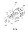
第15圖是從容器的後端部觀看的噴嘴接收器的解釋性立體圖; Figure 15 is an explanatory perspective view of the nozzle receiver viewed from the rear end of the container;

第16圖是在第13圖所示之狀態下的噴嘴接收器的頂部剖視圖; Figure 16 is a top sectional view of the nozzle receiver in the state shown in Figure 13;

第17圖是在第13圖所示之狀態下的噴嘴接收器的橫向剖視圖; Fig. 17 is a transverse sectional view of the nozzle receiver in the state shown in Fig. 13;

第18圖是噴嘴接收器的立體分解圖; Figure 18 is an exploded perspective view of the nozzle receiver;

第19圖是示例碳粉容器後端部朝下而掉落的狀態的解釋性示意圖; Fig. 19 is an explanatory diagram illustrating a state in which the toner container is dropped with its rear end facing downward;

第20圖是示例在包括第二擋門鉤子的碳粉容器被設置在裝置主體中之前的狀態的解釋性示意圖; FIG. 20 is an explanatory diagram illustrating a state before the toner container including the second shutter hook is set in the device main body;

第21圖是示例其中包括第二擋門鉤子的碳粉容器被設置在主體中的狀態的解釋性示意圖; FIG. 21 is an explanatory diagram illustrating a state in which a toner container including a second shutter hook is set in the main body;

第22圖是噴嘴擋門的解釋性剖視圖; Figure 22 is an explanatory cross-sectional view of a nozzle shutter;

第23圖是從噴嘴的前端部觀看的噴嘴擋門的解釋性立體圖; Figure 23 is an explanatory perspective view of the nozzle shutter viewed from the front end of the nozzle;

第24圖是從噴嘴的底端部觀看的噴嘴擋門的解釋性立體圖; Figure 24 is an explanatory perspective view of the nozzle shutter viewed from the bottom end of the nozzle;

第25圖是碳粉再補給裝置的傳送噴嘴的附近部分的解釋性剖視圖; Fig. 25 is an explanatory sectional view of the vicinity of the transfer nozzle of the toner resupply device;

第26圖是傳送噴嘴的噴嘴開口的附近部分的解釋性透視剖視圖; Figure 26 is an explanatory perspective sectional view of the vicinity of the nozzle opening of the transfer nozzle;

第27圖是從噴嘴的前端部觀看,當噴嘴擋門被拆卸時傳送噴嘴的附近部分的解釋性立體圖; FIG. 27 is an explanatory perspective view of the vicinity of the transfer nozzle when the nozzle shutter is detached, viewed from the front end of the nozzle;

第28圖是當噴嘴擋門被拆卸時噴嘴開口的附近部分的解釋性立體圖; Fig. 28 is an explanatory perspective view of the vicinity of the nozzle opening when the nozzle shutter is detached;

第29圖是用於首先旋轉碳粉容器接著旋轉輸送螺桿的結構的時序圖; Figure 29 is a timing diagram of a structure for first rotating the toner container and then rotating the conveying screw;

第30A圖是藉由使用相同的驅動源區分碳粉容器和輸送螺桿的旋轉時序的驅動傳送機的解釋性前視圖; FIG. 30A is an explanatory front view of a drive conveyor that differentiates the timing of rotation of the toner container and conveying screw by using the same drive source;

第30B圖是驅動傳送機的解釋性側面剖視圖; Figure 30B is an explanatory side cutaway view of the drive conveyor;

第31A圖是示例其中碳粉容器連接到碳粉再補給裝置,使得前端部開口的邊緣(周緣)和噴嘴接收器的邊緣處在旋轉軸方向上的相同的位置處之狀態的解釋性示意圖; FIG. 31A is an explanatory diagram illustrating a state in which the toner container is attached to the toner resupply device so that the edge (peripheral edge) of the front end opening and the edge of the nozzle receiver are at the same position in the direction of the rotation axis;

第31B圖是示例其中碳粉容器連接到碳粉再補給裝置,使得噴嘴接收器的邊緣相對於前端部開口的邊緣被定位在容器的後端部上的狀態的解釋性示意圖; FIG. 31B is an explanatory diagram illustrating a state in which the toner container is connected to the toner resupply device such that the edge of the nozzle receiver is positioned on the rear end of the container relative to the edge of the front opening;

第32圖是在被儲存狀態下碳粉容器的解釋性透視圖; Figure 32 is an explanatory perspective view of a toner container in a stored state;

第33圖是帽件連接至碳粉容器的前端部的附近部分的解釋性剖視圖; Fig. 33 is an explanatory sectional view of the vicinity of the front end portion of the cap connected to the toner container;

第34圖是當帽件具有吸附材料時碳粉容器之第一實施例的解釋性剖視圖; Figure 34 is an explanatory sectional view of the first embodiment of the toner container when the cap has an absorbent material;

第35圖是當帽件具有吸附材料時碳粉容器之第二實施例的解釋性剖視圖; Figure 35 is an explanatory cross-sectional view of a second embodiment of the toner container when the cap has an absorbent material;

第36圖是當帽件具有吸附材料時碳粉容器之第三實施例的解釋性剖視圖; Figure 36 is an explanatory cross-sectional view of a third embodiment of the toner container when the cap has an absorbent material;

第37圖是當帽件設置有碳粉洩漏防止器時碳粉容器之第一實施例的解釋性剖視圖; Figure 37 is an explanatory sectional view of the first embodiment of the toner container when the cap is provided with a toner leakage preventer;

第38圖是當帽件設置有碳粉洩漏防止器時碳粉容器之第二實施例的解釋性剖視圖; Figure 38 is an explanatory sectional view of a second embodiment of the toner container when the cap is provided with a toner leakage preventer;

第39圖是當帽件設置有碳粉洩漏防止器時碳粉容器之第三實施例的解釋性剖視圖; Figure 39 is an explanatory sectional view of a third embodiment of the toner container when the cap is provided with a toner leakage preventer;

第40圖是當帽件設置有碳粉洩漏防止器時碳粉容器之第四實施例的解釋性剖視圖; Figure 40 is an explanatory sectional view of a fourth embodiment of the toner container when the cap is provided with a toner leakage preventer;

第41圖是當帽件設置有碳粉洩漏防止器時碳粉容器之第五實施例的解釋性剖視圖; Figure 41 is an explanatory sectional view of a fifth embodiment of the toner container when the cap is provided with a toner leakage preventer;

第42圖是使用在透過螺紋接合方式固定至容器主體的噴嘴接收器中的容器擋門支撐器的解釋性立體圖; Figure 42 is an explanatory perspective view of a container door support for use in a nozzle receptacle secured to a container body by threaded engagement;

第43圖是示例在旋轉軸方向上的容器主體的解釋性前視圖; Fig. 43 is an explanatory front view of the container body in the direction of the axis of rotation;

第44圖是為了解釋擋門側面支撐部分具有橋接功能的配置而沿著第9圖中E-E剖面線之剖視圖; Figure 44 is a cross-sectional view along the E-E section line in Figure 9 in order to explain the configuration of the side support portion of the door with a bridging function;

第45A圖是為了解釋未提供橋接功能之配置而沿著在第9圖中E-E剖面線之剖視圖; Figure 45A is a cross-sectional view along the E-E section line in Figure 9 for the purpose of explaining the configuration that does not provide a bridging function;

第45B圖是為了解釋擋門側面支撐部分335a具有橋接功能的配置而沿著第9圖中E-E剖面線之示意剖視圖; Figure 45B is a schematic cross-sectional view along the section line E-E in Figure 9 in order to explain the configuration of the door side support portion 335a having a bridging function;

第46圖是示出根據實施例和比較例在容器中的碳粉剩餘量和再補給速度之間的關係的曲線圖; Fig. 46 is a graph showing the relationship between the remaining amount of toner in the container and the resupply speed according to the embodiment and the comparative example;

第47A圖是以抓取肋條作為抓取部分之配置的解釋性示意圖,特別係噴嘴 接收器的解釋性示意圖; Figure 47A is an explanatory diagram of the configuration of the grabbing rib as the grabbing part, especially the nozzle An explanatory schematic diagram of the receiver;

第47B圖是示例第47A圖中所示的噴嘴接收器被安裝在容器主體上之狀態的解釋性剖視圖; Figure 47B is an explanatory sectional view illustrating a state in which the nozzle receiver shown in Figure 47A is mounted on the container main body;

第47C圖是在第47A圖中所示的噴嘴接收器被安裝在其上的整個碳粉容器的側視剖視圖; Figure 47C is a side sectional view of the entire toner container with the nozzle receiver shown in Figure 47A mounted thereon;

第47D圖是包括在第47C圖中所示的碳粉容器中之容器擋門的立體圖; Figure 47D is a perspective view of a container door included in the toner container shown in Figure 47C;

第48A圖是示例根據第十四實施例之噴嘴接收器從碳粉容器的容器主體拆下的狀態的解釋性立體圖; 48A is an explanatory perspective view illustrating a state in which the nozzle receiver is detached from the container main body of the toner container according to the fourteenth embodiment;

第48B圖是噴嘴接收器接合突出件的放大視圖; Figure 48B is an enlarged view of the nozzle receiver engagement projection;

第49圖是根據第十四實施例之碳粉容器的前端部和容器設定區段的解釋性立體圖; Fig. 49 is an explanatory perspective view of a front end portion of a toner container and a container setting section according to a fourteenth embodiment;

第50A圖是根據第十四實施例之碳粉容器的前端部的附近部分的剖視圖; Figure 50A is a sectional view of the vicinity of the front end of the toner container according to the fourteenth embodiment;

第50B圖是在第50A圖中所示區域η的解釋性放大視圖; Figure 50B is an explanatory enlarged view of the region n shown in Figure 50A;

第51A圖是根據第十六實施例之碳粉容器的噴嘴接收器的解釋性立體圖; FIG. 51A is an explanatory perspective view of a nozzle receiver of a toner container according to a sixteenth embodiment;

第51B圖是根據第十六實施例之碳粉容器的容器主體解釋性立體圖; FIG. 51B is an explanatory perspective view of a container main body of a toner container according to a sixteenth embodiment;

第52A圖是根據第十七實施例之碳粉容器的噴嘴接收器的解釋性立體圖; FIG. 52A is an explanatory perspective view of a nozzle receiver of a toner container according to a seventeenth embodiment;

第52B圖是根據第十七實施例之碳粉容器的容器主體之解釋性立體圖; FIG. 52B is an explanatory perspective view of a container main body of a toner container according to a seventeenth embodiment;

第53A圖是根據第十八實施例之碳粉容器的前端部開口的解釋性放大立體圖; FIG. 53A is an explanatory enlarged perspective view of the front end opening of the toner container according to the eighteenth embodiment;

第53B圖是根據第十八實施例之碳粉容器的噴嘴接收器固定部分的解釋性放大剖視圖; FIG. 53B is an explanatory enlarged sectional view of a nozzle receiver fixing portion of a toner container according to an eighteenth embodiment;

第53C圖是根據第十八實施例之碳粉容器的前端部附近部分的解釋性放大立體圖; FIG. 53C is an explanatory enlarged perspective view of a portion near a front end of a toner container according to an eighteenth embodiment;

第54A圖是根據第十九實施例之碳粉容器的前端部開口的解釋性放大立體圖; FIG. 54A is an explanatory enlarged perspective view of the front end opening of the toner container according to the nineteenth embodiment;

第54B圖是根據第十九實施例之碳粉容器的噴嘴接收器之固定部分的解釋性放大剖視圖; FIG. 54B is an explanatory enlarged sectional view of a fixed portion of a nozzle receiver of a toner container according to a nineteenth embodiment;

第55圖是固定於碳粉再補給裝置的連接器和碳粉容器的前端部之解釋性立體圖; Figure 55 is an explanatory perspective view of the front end of the connector and toner container secured to the toner resupply device;

第56圖是當ID標籤(ID晶片)固持結構被拆卸時碳粉容器的前端部和連接 器的解釋性立體圖; Fig. 56 is the front end and connection of the toner container when the ID tag (ID chip) holding structure is disassembled explanatory perspective view of the device;

第57圖是當ID標籤(ID晶片)被暫時地連接至ID標籤固持器時碳粉容器的前端部和連接器的解釋性立體圖; Figure 57 is an explanatory perspective view of the front end of the toner container and the connector when the ID tag (ID chip) is temporarily connected to the ID tag holder;

第58A圖是ID標籤三視圖中的前視圖; Figure 58A is a front view in three views of the ID tag;

第58B圖是ID標籤三視圖中的側視圖; Figure 58B is a side view of the ID tag in three views;

第58C圖是ID標籤三視圖中的後視圖; Figure 58C is a rear view of the ID tag in three views;

第59圖是示例ID標籤、ID標籤固持器以及連接器的相互位置關係的立體圖; Fig. 59 is a perspective view of the mutual positional relationship between an example ID tag, an ID tag holder, and a connector;

第60圖是示例ID標籤與連接器接合的狀態的立體圖; Figure 60 is a perspective view of a state where an example ID tag is engaged with a connector;

第61A圖和第61B圖是ID標籤的電路和連接器電路的電路圖; Figure 61A and Figure 61B are circuit diagrams of the circuit of the ID tag and the circuit of the connector;

第62A圖是由連接器固持的ID標籤的前視圖; Figure 62A is a front view of an ID tag held by a connector;

第62B圖是繞著定位ID標籤孔旋轉的ID標籤的前視圖; Figure 62B is a front view of an ID tag rotated about a positioning ID tag hole;

第63圖是示例與導電檢測裝置的探針接觸的ID標籤的示意圖; Figure 63 is a schematic diagram illustrating an ID tag in contact with a probe of a conductive detection device;

第64A圖是當在旋轉軸方向上的接收開口的位置與在容器的前端部上的前端部開口的位置相同時,碳粉容器的前端部的附近部分的解釋性立體圖; FIG. 64A is an explanatory perspective view of the vicinity of the front end of the toner container when the position of the receiving opening in the direction of the rotation axis is the same as the position of the front end opening on the front end of the container;

第64B圖是碳粉容器的前端部的附近部分的解釋性剖視圖; Fig. 64B is an explanatory sectional view of the vicinity of the front end of the toner container;

第65A圖是設置有圓柱形密封件的噴嘴擋門的解釋性立體圖; Figure 65A is an explanatory perspective view of a nozzle shutter provided with a cylindrical seal;

第65B圖是設置有圓柱形密封件的噴嘴擋門的解釋性剖視圖;以來 Figure 65B is an explanatory cross-sectional view of a nozzle shutter provided with a cylindrical seal;

第66圖是示例容器開口的外表面的直徑、噴嘴接收固定部分的內直徑以及包括碳粉再補給裝置的容器設定區段的部分的直徑的關係的解釋性示意圖。 FIG. 66 is an explanatory diagram illustrating the relationship of the diameter of the outer surface of the opening of the container, the inner diameter of the nozzle receiving and fixing portion, and the diameter of the portion including the container setting section of the toner resupplying device.

以下配合圖式及元件符號對本發明的實施方式做更詳細的說明,俾使熟習該項技藝者在研讀本說明書後能據以實施。 The implementation of the present invention will be described in more detail below with reference to the drawings and reference symbols, so that those skilled in the art can implement it after studying this specification.

<第一實施例> <First embodiment>

在下文中,將針對根據本發明的影像形成設備的影印機(以下被簡稱為影印機500)的示例性實施例進行解釋。 Hereinafter, explanation will be made regarding an exemplary embodiment of a photocopier (hereinafter simply referred to as a photocopier 500 ) of an image forming apparatus according to the present invention.

第2圖是根據第一到第十二實施例之影印機500的整體配置圖。影印機500包括影印機主體(以下稱為印表機100)、供紙桌面(以下稱為供 紙器200)以及安裝在印表機100上的掃描機(以下稱為掃描機400)。 FIG. 2 is an overall configuration diagram of a photocopier 500 according to the first to twelfth embodiments. The photocopier 500 includes a photocopier main body (hereinafter referred to as the printer 100), a paper feeding table (hereinafter referred to as the paper supply table). Paper 200) and a scanner installed on the printer 100 (hereinafter referred to as scanner 400).

作為相應於不同顏色(黃色,品紅色,青色,黑色)的四種粉末容器的碳粉容器32(Y,M,C,K),係可拆卸地連接至設置在印表機100的上部分中的容器固持區段70。中間轉移單元85則設置在容器固持區段70下方。 Toner containers 32 (Y, M, C, K), which are four types of powder containers corresponding to different colors (yellow, magenta, cyan, black), are detachably attached to the upper portion provided on the printer 100. The container holding section 70 in. The intermediate transfer unit 85 is arranged below the container holding section 70 .

中間轉移單元85包括中間轉移帶48、四個主要轉移偏壓輥49(Y,M,C,K)、第二轉移備用輥82、複數個張力輥、中間轉移清潔器(未顯示)等。中間轉移帶48由多個輥拉伸和支撐,且隨著是所述棍中的一個輥的第二轉移備用輥82的旋轉在第2圖所示的箭頭方向上無限地移動。 The intermediate transfer unit 85 includes an intermediate transfer belt 48, four main transfer bias rollers 49 (Y, M, C, K), a second transfer backup roller 82, a plurality of tension rollers, an intermediate transfer cleaner (not shown) and the like. The intermediate transfer belt 48 is stretched and supported by a plurality of rollers, and moves infinitely in the direction of the arrow shown in FIG. 2 with the rotation of the second transfer backup roller 82 which is one of the rollers.

在印表機100中,相應於各自顏色的四個影像形成單元46(Y,M,C,K)係以串聯的方式設置,以面朝向中間轉移帶48。四個碳粉再補給裝置60(Y,M,C,K)分別地設置在四個碳粉容器32(Y,M,C,K)的下方。碳粉再補給裝置60(Y,M,C,K)向相應於各自顏色的影像形成單元46(Y,M,C,K)的顯影裝置(粉末使用單元)供應(再補給)容納在碳粉容器32(Y,M,C,K)中的碳粉。 In the printer 100 , four image forming units 46 (Y, M, C, K) corresponding to respective colors are arranged in series so as to face toward the intermediate transfer belt 48 . Four toner resupply devices 60 (Y, M, C, K) are respectively provided below the four toner containers 32 (Y, M, C, K). The toner resupplying device 60 (Y, M, C, K) supplies (resupplies) the carbon contained in the toner to the developing device (powder using unit) of the image forming unit 46 (Y, M, C, K) corresponding to the respective colors. Toner in the powder container 32 (Y, M, C, K).

如第2圖所示,印表機100包括作為在四個影像形成單元46下方的潛像形成裝置的曝光裝置47。曝光裝置47根據由掃描機400所讀取的原影像的影像資訊,或者根據自如個人電腦等外部設備輸入的影像資訊,將光感受器41(將在下文中詳細描述)的表面曝光在光線下,使得靜電潛像在曝光光感受器41上形成。印表機100的曝光裝置47使用具有雷射二極體之雷射掃描系統。然而,也可以使用具有其它配置(例如,具有LED陣列)的曝光器件。 As shown in FIG. 2 , the printer 100 includes an exposure device 47 as a latent image forming device below the four image forming units 46 . The exposure device 47 exposes the surface of the photoreceptor 41 (described in detail below) to light according to the image information of the original image read by the scanner 400, or according to the image information input from external equipment such as a personal computer, so that An electrostatic latent image is formed on the exposed photoreceptor 41 . The exposure device 47 of the printer 100 uses a laser scanning system with a laser diode. However, exposure devices with other configurations (eg, with an array of LEDs) may also be used.

第3圖是用於黃色的影像形成單元46Y的整體配置示意圖。 FIG. 3 is a schematic diagram of the overall configuration of the image forming unit 46Y for yellow.

影像形成單元46Y包括作為潛像載體的鼓形光感受器41Y。影像形成單元46Y也包括作為充電工具的充電輥44Y、作為顯影工具的顯影裝置50Y、光感受器清潔裝置42Y以及中和裝置(未顯示),該等裝置皆設置於光感受器41Y的周圍。影像形成步驟(充電步驟、曝光步驟、顯影步驟、轉移步驟以及清潔步驟)係在光感受器41Y上執行,使得黃色影像得以在光感受器41Y上形成。 The image forming unit 46Y includes a drum-shaped photoreceptor 41Y as a latent image carrier. The image forming unit 46Y also includes a charging roller 44Y as a charging means, a developing device 50Y as a developing means, a photoreceptor cleaning device 42Y, and a neutralization device (not shown), which are provided around the photoreceptor 41Y. Image forming steps (charging step, exposing step, developing step, transferring step, and cleaning step) are performed on the photoreceptor 41Y, so that a yellow image is formed on the photoreceptor 41Y.

除了使用的碳粉的顏色是不同的之外,其它三個影像形成單元 46(M,C,K)與用於黃色的影像形成單元46Y具有幾乎相同的相同配置,相應於各自碳粉顏色的影像在影像形成單元46(M,C,K)上形成。在下文中,將適當地省略其它三個影像形成單元46(M,C,K)的解釋,並且僅針對用於黃色的影像形成單元46Y進行解釋。 Except the color of the toner used is different, the other three image forming units 46(M,C,K) has almost the same configuration as the image forming unit 46Y for yellow, on which images corresponding to the respective toner colors are formed. Hereinafter, explanations of the other three image forming units 46 (M, C, K) will be appropriately omitted, and only the image forming unit 46Y for yellow will be explained.

在第3圖中,光感受器41Y被驅動馬達(未顯示)順時針地旋轉。光感受器41Y的表面在面朝充電輥44Y的位置處被均勻地充電(充電步驟)。接著,光感受器41Y的表面到達由曝光裝置47發射的雷射L的照射位置,其中,用於黃色的靜電潛像透過曝光掃描而形成(曝光步驟)。光感受器41Y的表面接著到達面朝顯影裝置50Y的位置,使得靜電潛像得以顯影且黃色碳粉影像得以形成(顯影步驟)。 In Fig. 3, the photoreceptor 41Y is rotated clockwise by a drive motor (not shown). The surface of the photoreceptor 41Y is uniformly charged at a position facing the charging roller 44Y (charging step). Next, the surface of the photoreceptor 41Y reaches the irradiation position of the laser light L emitted by the exposure device 47, in which an electrostatic latent image for yellow is formed through exposure scanning (exposure step). The surface of the photoreceptor 41Y then reaches a position facing the developing device 50Y, so that the electrostatic latent image is developed and a yellow toner image is formed (developing step).

中間轉移帶48夾在中間轉移單元85的四個主要轉移偏壓輥49(Y,M,C,K)以及光感受器41(Y,M,C,K)之間,以形成主要轉移輥隙。具有與碳粉的極性相反極性的轉移偏壓件被應用至主要轉移偏壓輥49(Y,M,C,K)上。 The intermediate transfer belt 48 is sandwiched between the four main transfer bias rollers 49 (Y, M, C, K) of the intermediate transfer unit 85 and the photoreceptors 41 (Y, M, C, K) to form a main transfer nip . A transfer bias member having a polarity opposite to that of the toner is applied to the main transfer bias rollers 49 (Y, M, C, K).

透過顯影步驟形成的碳粉影像係形成在光感受器41Y的表面上,光感受器41Y的表面到達面朝橫跨中間轉移帶48的主要轉移偏壓輥49Y的主要轉移輥隙,並且,在光感受器41Y上的碳粉影像轉移至位於主要轉移輥隙處的中間轉移帶48上(主要轉移步驟)。在此時,少量的未轉移碳粉停留在光感受器41Y上。碳粉影像從光感受器41Y的表面轉移到在主要轉移輥隙處的中間轉移帶48上後,光感受器41Y的表面到達面朝光感受器清潔裝置42Y的位置。在該位置處,殘留在光感受器41Y上的未轉移碳粉由清潔葉片42a機械式地收集(清潔步驟)。光感受器41Y的表面最後到達面朝中和裝置(未顯示)的位置,其中,在光感受器41Y上的殘餘電位被移除。透過這種方式,完成在光感受器41Y上所執行的一系列影像形成步驟。 The toner image formed by the developing step is formed on the surface of the photoreceptor 41Y which reaches the main transfer nip facing the main transfer bias roller 49Y across the intermediate transfer belt 48, and, on the photoreceptor 41Y The toner image on 41Y is transferred to the intermediate transfer belt 48 at the main transfer nip (main transfer step). At this time, a small amount of untransferred toner remains on the photoreceptor 41Y. After the toner image is transferred from the surface of the photoreceptor 41Y onto the intermediate transfer belt 48 at the main transfer nip, the surface of the photoreceptor 41Y reaches a position facing the photoreceptor cleaning device 42Y. At this position, untransferred toner remaining on the photoreceptor 41Y is mechanically collected by the cleaning blade 42a (cleaning step). The surface of the photoreceptor 41Y finally reaches a position facing a neutralization device (not shown), where the residual potential on the photoreceptor 41Y is removed. In this way, a series of image forming steps performed on the photoreceptor 41Y are completed.

以上影像形成步驟也以與用於黃色的影像形成單元46Y上的相同的方式在其它影像形成單元46(M,C,K)上執行。具體而言,設置於影像形成單元46(M,C,K)下方的曝光裝置47根據影像資訊朝向影像形成單元46(M,C,K)的光感受器41(M,C,K)發射雷射L。更具體而言,曝光裝置47發射來自光源的雷射L,經由多個光學元件利用雷射L照射 光感受器41(M,C,K),並且同時透過旋轉的多角鏡掃描雷射L。接著,透過顯影步驟形成在光感受器41(M,C,K)上的各個顏色的碳粉影像被轉移到中間轉移帶48上。 The above image forming steps are also performed on the other image forming units 46 (M, C, K) in the same manner as on the image forming unit 46Y for yellow. Specifically, the exposure device 47 disposed under the image forming unit 46 (M, C, K) emits a laser beam toward the photoreceptor 41 (M, C, K) of the image forming unit 46 (M, C, K) according to the image information. Shoot L. More specifically, the exposure device 47 emits laser light L from a light source, and irradiates with the laser light L through a plurality of optical elements. The photoreceptors 41 (M, C, K) scan the laser L through the rotating polygon mirror at the same time. Next, the toner images of the respective colors formed on the photoreceptors 41 (M, C, K) through the developing step are transferred to the intermediate transfer belt 48 .

此時,中間轉移帶48在第2圖中的箭頭的方向上移動,並從而穿過主要轉移偏壓輥49(Y,M,C,K)的主要轉移輥隙。因此,形成在光感受器41(Y,M,C,K)上的各個顏色的碳粉影像被疊加到作為主要轉移件的中間轉移帶48上,使得彩色碳粉影像得以形成在中間轉移帶48上。 At this time, the intermediate transfer belt 48 moves in the direction of the arrow in FIG. 2 , and thereby passes through the main transfer nip of the main transfer bias rollers 49 (Y, M, C, K). Therefore, the toner images of the respective colors formed on the photoreceptors 41 (Y, M, C, K) are superimposed on the intermediate transfer belt 48 as the main transfer member, so that the color toner images are formed on the intermediate transfer belt 48 superior.

彩色碳粉影像透過疊加各個顏色的碳粉影像形成在中間轉移帶48上後,中間轉移帶48接著到達面朝第二轉移輥89的位置。在這個位置上,中間轉移帶48係夾入至第二轉移備用輥82和第二轉移輥89之間,形成第二轉移輥隙。形成在中間轉移帶48上的彩色碳粉影像被轉移到紙張等記錄媒介物P上,所述記錄媒介物P則被傳送到第二轉移輥隙的位置。在此,未轉移到紀錄媒介物P上的未轉移碳粉殘留在中間轉移帶48上。已經穿過第二轉移輥隙的中間轉移帶48到達中間轉移清潔器(未顯示)的位置,其中,在該表面上的未轉移碳粉被收集。透過上述方式,完成在中間轉移帶48上執行的一系列轉移步驟。 After the color toner image is formed on the intermediate transfer belt 48 by superimposing the toner images of each color, the intermediate transfer belt 48 then arrives at a position facing the second transfer roller 89 . In this position, the intermediate transfer belt 48 is sandwiched between the second transfer backup roll 82 and the second transfer roll 89, forming a second transfer nip. The color toner image formed on the intermediate transfer belt 48 is transferred to a recording medium P such as paper, and the recording medium P is transported to the position of the second transfer nip. Here, untransferred toner that has not been transferred onto the recording medium P remains on the intermediate transfer belt 48 . The intermediate transfer belt 48 having passed through the second transfer nip reaches the position of an intermediate transfer cleaner (not shown) where untransferred toner on the surface is collected. Through the above method, a series of transfer steps performed on the intermediate transfer belt 48 are completed.

在下文中,將針對記錄媒介物P的移動進行解釋。 Hereinafter, an explanation will be given regarding movement of the recording medium P. FIG.

記錄媒介物P經由給料輥27、註冊輥對28等從設置於印表機100下方的供紙器200的給料盤26被傳送到第二轉移輥隙。具體而言,多個記錄媒介物P係堆積在給料盤26中。當第2圖中的給料輥27被逆時針方向旋轉時,最頂部的記錄媒介物P就被供應到在註冊輥對28的兩個輥之間的輥隙。 The recording medium P is conveyed from the feed tray 26 of the sheet feeder 200 disposed below the printer 100 to the second transfer nip via a feed roller 27 , a registration roller pair 28 , and the like. Specifically, a plurality of recording media P are stacked in the feed tray 26 . When the feed roller 27 in FIG. 2 is rotated counterclockwise, the topmost recording medium P is supplied to the nip between the two rollers of the registration roller pair 28 .

藉由停止註冊輥對28的旋轉,被傳送到註冊輥對28的紀錄媒介物P暫時停止在註冊輥對28的輥之間的輥隙的位置處。根據在中間轉移帶48上的彩色碳粉影像到達第二轉移輥隙所定的時間旋轉註冊輥對28,以朝向第二轉移輥隙傳送記錄媒介物P。如此一來,可將期望的彩色影像形成在記錄媒介物P上。 By stopping the rotation of the registration roller pair 28 , the recording medium P conveyed to the registration roller pair 28 is temporarily stopped at the position of the nip between the rollers of the registration roller pair 28 . The pair of registration rollers 28 are rotated according to the time determined by the color toner image on the intermediate transfer belt 48 to reach the second transfer nip to convey the recording medium P toward the second transfer nip. In this way, a desired color image can be formed on the recording medium P.

記錄媒介物P上的彩色碳粉影像在第二轉移輥隙處被轉移後,記錄媒介物P被傳送到固定裝置86的位置。在固定裝置86中,在記錄媒介物P的表面上轉移的彩色碳粉影像透過固定帶和壓輥所產生的熱和所施 加的壓力被固定到紀錄媒介物P。穿過固定裝置86的紀錄媒介物P經由在排放輥對29的輥之間的輥隙被排放到設備的外部。通過排放輥對29被排放到設備外部的記錄媒介物P作為輸出影像被連續地堆疊在堆疊區段30上。透過上述方式,完成在影印機500中的一系列影像形成步驟。 After the color toner image on the recording medium P is transferred at the second transfer nip, the recording medium P is transported to the position of the fixture 86 . In the fixing device 86, the color toner image transferred on the surface of the recording medium P passes through the heat generated by the fixing belt and the pressure roller and the applied force. The applied pressure is fixed to the recording medium P. The recording medium P passing through the fixing device 86 is discharged to the outside of the apparatus via the nip between the rollers of the discharge roller pair 29 . The recording media P discharged to the outside of the apparatus by the discharge roller pair 29 are continuously stacked on the stacking section 30 as output images. Through the above method, a series of image forming steps in the photocopier 500 are completed.

在下文中,將針對影像形成單元46中的顯影裝置50的配置和操作進行詳細地描述。在此,將使用黃色的影像形成單元46Y借助於實施例來解釋。然而,所述相同的敘述也可應用於用於其它顏色的影像形成單元46(M,C,K)。 Hereinafter, the configuration and operation of the developing device 50 in the image forming unit 46 will be described in detail. Here, explanation will be made by way of example using the yellow image forming unit 46Y. However, the same statement is also applicable to image forming units 46 (M, C, K) for other colors.

如第3圖所示,顯影裝置50Y包括顯影輥51Y、校正器葉片52Y、兩個顯影劑輸送螺桿55Y、碳粉密度感測器56Y等等。顯影輥51Y面向光感受器41Y。校正器葉片52Y面向顯影輥51Y。兩個顯影劑輸送螺桿55Y係設置於兩個顯影劑容納部分(53Y,54Y)的內部。顯影輥51Y包括固定在其內部的磁體以及繞著磁體輥旋轉的套筒。由載體和碳粉形成的兩構件型顯影劑G被儲存在第一顯影劑容納部分53Y和第二顯影劑容納部分54Y中。第二顯影劑容納部分54Y經由形成在其上部的開口與碳粉下降通道64Y連通。碳粉密度感測器56Y檢測被儲存在第二顯影劑容納部分54Y中的顯影劑G中的碳粉密度。 As shown in FIG. 3, the developing device 50Y includes a developing roller 51Y, a corrector blade 52Y, two developer conveying screws 55Y, a toner density sensor 56Y, and the like. The developing roller 51Y faces the photoreceptor 41Y. The corrector blade 52Y faces the developing roller 51Y. Two developer conveying screws 55Y are provided inside the two developer accommodating portions (53Y, 54Y). The developing roller 51Y includes a magnet fixed therein and a sleeve that rotates around the magnet roller. A two-member type developer G formed of a carrier and toner is stored in the first developer accommodating portion 53Y and the second developer accommodating portion 54Y. The second developer accommodating portion 54Y communicates with the toner descending passage 64Y via an opening formed in an upper portion thereof. The toner density sensor 56Y detects the toner density in the developer G stored in the second developer accommodating portion 54Y.

顯影裝置50中的顯影劑G在第一顯影劑容納部分53Y和第二顯影劑容納部分54Y之間循環,同時被兩個顯影劑輸送螺桿55Y所攪動。由於在顯影輥51Y中的磁輥所形成的磁場,在第一顯影劑容納部分53Y中的顯影劑G被供應到且被固持在顯影輥51Y的套管的表面上,同時,顯影劑G藉由其中一個顯影劑輸送螺桿55Y中被輸送。顯影輥51Y的套管如第3圖中的箭頭所指示的順時針旋轉,以及在顯影輥51Y上被固持的顯影劑G隨著套筒的旋轉在顯影輥51Y上移動。在這時候,由於對顯影劑G中的載體充電而產生的摩擦帶電,在顯影劑G中的碳粉通過向相對於載體的極性的電位充電而靜電地黏附到載體,並與被形成在顯影輥51Y上的磁場所吸引的載體一起在顯影輥51Y上被運載。 The developer G in the developing device 50 circulates between the first developer accommodating portion 53Y and the second developer accommodating portion 54Y while being agitated by the two developer conveying screws 55Y. Due to the magnetic field formed by the magnetic roller in the developing roller 51Y, the developer G in the first developer accommodating portion 53Y is supplied to and held on the surface of the sleeve of the developing roller 51Y, and at the same time, the developer G is It is conveyed by one of the developer conveying screws 55Y. The sleeve of the developing roller 51Y rotates clockwise as indicated by the arrow in FIG. 3 , and the developer G held on the developing roller 51Y moves on the developing roller 51Y along with the rotation of the sleeve. At this time, the toner in the developer G electrostatically adheres to the carrier by being charged to a potential with respect to the polarity of the carrier due to triboelectric charge generated by charging the carrier in the developer G, and is formed in the developing The carriers attracted by the magnetic field on the roller 51Y are carried together on the developing roller 51Y.

固持在顯影輥51Y上的顯影劑G在第3圖中的箭頭方向上被傳送,並到達其中校正器葉片52Y和顯影輥51Y面向彼此的校正器部分。當在顯影輥51Y上的顯影劑G穿過校正器部分時,其被調節到合適的數 量,然後被傳送到面朝光感受器41Y的顯影區域。在該顯影區域中,通過形成在顯影輥51Y和光感受器41Y之間的顯影電場,在顯影劑G中的碳粉黏附到形成在光感受器41Y上的潛像。殘留在已穿過顯影區域的顯影輥51Y的表面上的顯影劑G隨著套筒的旋轉到達第一顯影劑容納部分53Y的上部分,其中在該上部份處,顯影劑G與顯影輥51Y分離。 The developer G held on the developing roller 51Y is conveyed in the arrow direction in FIG. 3 , and reaches the corrector portion where the corrector blade 52Y and the developing roller 51Y face each other. When the developer G on the developing roller 51Y passes through the corrector portion, it is adjusted to an appropriate number. amount, and then transferred to the developing area facing the photoreceptor 41Y. In this developing area, the toner in the developer G adheres to the latent image formed on the photoreceptor 41Y by the developing electric field formed between the developing roller 51Y and the photoreceptor 41Y. The developer G remaining on the surface of the developing roller 51Y that has passed through the developing area reaches the upper portion of the first developer accommodating portion 53Y along with the rotation of the sleeve, where the developer G is mixed with the developing roller. 51Y is isolated.

在顯影裝置50Y中的顯影劑G的碳粉密度被調節到一預定的範圍。具體而言,根據顯影過程在顯影裝置50Y中所消耗的顯影劑G之碳粉的量,碳粉再補給裝置60Y(在下文中會有詳細描述)將被容納在碳粉容器32Y中的碳粉供應到第二顯影劑容納部分54Y。 The toner density of the developer G in the developing device 50Y is adjusted to a predetermined range. Specifically, according to the amount of toner of the developer G consumed in the developing device 50Y during the developing process, the toner resupplying device 60Y (described in detail below) will be filled with the toner contained in the toner container 32Y It is supplied to the second developer accommodating portion 54Y.

被供應到第二顯影劑容納部分54Y的碳粉在第一顯影劑容納部分53Y和第二顯影劑容納部分54Y之間循環,同時透過兩個顯影劑輸送螺桿55Y將碳粉與顯影劑G混合並攪動。 The toner supplied to the second developer accommodating portion 54Y circulates between the first developer accommodating portion 53Y and the second developer accommodating portion 54Y while mixing the toner with the developer G through the two developer conveying screws 55Y. and stir.

在下文中將針對碳粉再補給裝置60(Y,M,C,K)進行解釋。 Hereinafter, explanations will be made with respect to the toner resupplying devices 60 (Y, M, C, K).

第4圖是碳粉容器32Y與碳粉再補給裝置60Y之連接方式的示意圖。第5圖是四個碳粉容器32(Y,M,C,K)與容器固持區段70之間的連接方式的示意立體圖。 FIG. 4 is a schematic diagram of the connection between the toner container 32Y and the toner resupply device 60Y. FIG. 5 is a schematic perspective view of the connection between the four toner containers 32 (Y, M, C, K) and the container holding section 70 .

根據在各個顏色的顯影裝置50(Y,M,C,K)中的碳粉消耗量,透過各個顏色的碳粉再補給裝置60(Y,M,C,K),將連接至印表機100的容器固持區段70上的碳粉容器32(Y,M,C,K)中的碳粉適當地供應到顯影裝置50(Y,M,C,K)。在這個時候,在碳粉容器32(Y,M,C,K)中的碳粉被設置用於各自顏色的碳粉再補給裝置60(Y,M,C,K)再補給。四個碳粉再補給裝置60(Y,M,C,K)具有幾乎相同的配置,且除了使用於影像形成步驟的碳粉的顏色不同外,碳粉容器32(Y,M,C,K)也具有幾乎相同的配置。因此,僅針對碳粉再補給裝置60Y和用於黃色的碳粉容器32Y進行以下的解釋,並且,將適當地省略碳粉再補給裝置60(M,C,K)和用於其它三種顏色的碳粉容器的解釋。 According to the toner consumption in the developing device 50 (Y, M, C, K) of each color, through the toner resupplying device 60 (Y, M, C, K) of each color, will be connected to the printer The toner in the toner container 32 (Y, M, C, K) on the container holding section 70 of 100 is appropriately supplied to the developing device 50 (Y, M, C, K). At this time, the toner in the toner container 32 (Y, M, C, K) is set for resupply by the toner resupply device 60 (Y, M, C, K) of the respective colors. The four toner resupplying devices 60 (Y, M, C, K) have almost the same configuration, and the toner container 32 (Y, M, C, K ) also has almost the same configuration. Therefore, the following explanation is made only for the toner resupply unit 60Y and the toner container 32Y for yellow, and the toner resupply unit 60 (M, C, K) and the toner container 32Y for the other three colors will be appropriately omitted. Explanation of the toner container.

碳粉再補給裝置60(Y,M,C,K)係由容器固持區段70、傳送噴嘴611(Y,M,C,K)、輸送螺桿614(Y,M,C,K)、碳粉下降通道64(Y,M,C,K)和容器驅動區段91(Y,M,C,K)所形成。 Toner replenishing device 60 (Y, M, C, K) is composed of container holding section 70, delivery nozzle 611 (Y, M, C, K), delivery screw 614 (Y, M, C, K), carbon The powder descending channel 64 (Y, M, C, K) and the container driving section 91 (Y, M, C, K) are formed.

當碳粉容器32Y在第4圖中的箭頭Q的方向上移動且連接至印 表機100的容器固持區段70時,碳粉再補給裝置60Y的傳送噴嘴611Y隨著連接步驟從碳粉容器32Y的前端部被插入。作為結果,碳粉容器32Y和傳送噴嘴611Y彼此互相連通。下文中,將針對能夠隨著連接操作而使兩者互相連通的配置進行詳細描述。 When the toner container 32Y moves in the direction of the arrow Q in Fig. 4 and is connected to the printer In the container holding section 70 of the watch machine 100, the transfer nozzle 611Y of the toner resupply device 60Y is inserted from the front end of the toner container 32Y following the connecting step. As a result, the toner container 32Y and the transfer nozzle 611Y communicate with each other. Hereinafter, a detailed description will be given for a configuration capable of making the two communicate with each other along with the connection operation.

作為為第一到第十二實施例共有的碳粉容器,碳粉容器32Y適當地為圓柱形的碳粉瓶,並且主要包括非旋轉地由容器固持區段70固持的容器前端部蓋子34Y,且包括與容器齒輪301Y合併的容器主體33Y。容器主體33Y被固持,以相對於容器前端部蓋子34Y旋轉。 As a toner container common to the first to twelfth embodiments, the toner container 32Y is suitably a cylindrical toner bottle, and mainly includes a container front end cap 34Y non-rotatably held by the container holding section 70, And includes the container main body 33Y combined with the container gear 301Y. The container main body 33Y is held to rotate relative to the container front end cap 34Y.

容器固持區段70主要包括容器蓋子接收區段73、容器接收區段72以及插入孔區段71。容器蓋子接收區段73是用於固持碳粉容器32Y的容器前端部的區段。容器蓋子接收區段72是用於固持碳粉容器32Y的容器主體33Y的區段。插入孔區段71形成使用於碳粉容器32Y的連接步驟中的插入孔。當設置於影印機500前側面(在垂直於第2圖的紙張方向上的前側面)上的主體蓋子(未顯示)被打開時,容器固持區段70的插入孔區段71被曝光。碳粉容器32(Y,M,C,K)(碳粉容器32在縱向方向中的連接/拆卸步驟被視為連接/拆卸方向)中的每一個的連接/拆卸操作從影印機500的前側面執行,同時,碳粉容器32(Y,M,C,K)的各個縱向方向皆平行於該水平方向。在第4圖中的設定蓋子608Y是容器固持區段70的容器蓋子接收區段73的一部分。 The container holding section 70 mainly includes a container cap receiving section 73 , a container receiving section 72 and an insertion hole section 71 . The container cap receiving section 73 is a section for holding the container front end portion of the toner container 32Y. The container cover receiving section 72 is a section for holding the container main body 33Y of the toner container 32Y. The insertion hole section 71 forms an insertion hole used in the attaching step of the toner container 32Y. When a main body cover (not shown) provided on the front side of the photocopier 500 (the front side in the direction perpendicular to the paper of FIG. 2 ) is opened, the insertion hole section 71 of the container holding section 70 is exposed. The attachment/detachment operation of each of the toner containers 32 (Y, M, C, K) (the attachment/detachment steps of the toner container 32 in the longitudinal direction is regarded as the attachment/detachment direction) is performed from the front of the photocopier 500. It is performed sideways, and at the same time, each longitudinal direction of the toner container 32 (Y, M, C, K) is parallel to the horizontal direction. The set cap 608Y in FIG. 4 is part of the container cap receiving section 73 of the container holding section 70 .

容器接收區段72以其縱向長度大約與容器主體33Y的縱向長度相同之配置來形成。容器蓋子接收區段73設置在縱向方向(連接/拆卸方向)上的容器接收區段72的容器前端部上,以及插入孔區段71設置在縱向方向上的容器接收區段72的一個端部上。因此,隨著碳粉容器32Y的連接步驟,容器前端部蓋子34Y首先穿過插入孔區段71,在容器接納區段72上滑動一段時間並最後被連接到容器蓋子接納區段73。 The container receiving section 72 is formed in such a configuration that its longitudinal length is approximately the same as that of the container main body 33Y. The container cap receiving section 73 is provided on the container front end portion of the container receiving section 72 in the longitudinal direction (attachment/detachment direction), and the insertion hole section 71 is provided at one end of the container receiving section 72 in the longitudinal direction superior. Therefore, following the attaching step of the toner container 32Y, the container front end cover 34Y first passes through the insertion hole section 71 , slides on the container receiving section 72 for a while and is finally attached to the container cover receiving section 73 .

在容器前端部蓋子34Y連接至容器蓋子接納區段73的情形下,當包括驅動馬達或驅動齒輪等容器驅動區段91Y經由容器驅動齒輪601Y向設置在容器主體33Y中的容器齒輪輸入旋轉驅動時,容器主體33Y在第4圖中的箭頭A的方向上旋轉。隨著容器主體33Y的旋轉,形成在容器主體33Y的內表面上的螺旋形的螺旋肋條302Y將在容器主體33Y中的 碳粉沿著容器主體的縱向方向在第4圖中從左向右傳送。藉此,將碳粉從容器前端部蓋子34Y側面供應到傳送噴嘴611Y的內部。 In the case where the container front end cap 34Y is connected to the container cap receiving section 73, when the container driving section 91Y including a driving motor or a driving gear inputs rotational drive to the container gear provided in the container main body 33Y via the container driving gear 601Y , the container main body 33Y rotates in the direction of the arrow A in FIG. 4 . As the container main body 33Y rotates, the helical spiral rib 302Y formed on the inner surface of the container main body 33Y will be in the container main body 33Y. The toner is conveyed from left to right in Figure 4 along the longitudinal direction of the container body. Thereby, toner is supplied from the side of the container front end cover 34Y to the inside of the delivery nozzle 611Y.

輸送螺桿614Y設置在傳送噴嘴611Y中。當容器驅動區段91Y將旋轉驅動輸入到輸送螺桿齒輪605Y時,輸送螺桿614Y旋轉,並將被供應到傳送噴嘴611Y中的碳粉傳送。在傳送方向上的傳送噴嘴611Y的下游端部連接到碳粉下降通道64Y,以及由輸送螺桿614Y傳送的碳粉通過重力沿著碳粉下降通道64Y掉落,並被供應到顯影裝置50Y(第二顯影劑容納部分54Y)。 A conveying screw 614Y is provided in the conveying nozzle 611Y. When the container driving section 91Y inputs rotational drive to the conveying screw gear 605Y, the conveying screw 614Y rotates, and conveys the toner supplied into the conveying nozzle 611Y. The downstream end portion of the conveying nozzle 611Y in the conveying direction is connected to the toner descending passage 64Y, and the toner conveyed by the conveying screw 614Y falls along the toner descending passage 64Y by gravity, and is supplied to the developing device 50Y (No. Two developer accommodating portion 54Y).

當使用壽命結束時,碳粉容器32(Y,M,C,K)被新的碳粉容器所替換(當容器因為碳粉幾乎被消耗完而變空時)。握把303設置在相對於縱向方向上的容器前端部蓋子34的碳粉容器32的端部上。當碳粉容器32被替換時,操作人員可以握住握把303,以拖出並拆卸連接的碳粉容器32。 The toner container 32 (Y, M, C, K) is replaced by a new toner container when the service life ends (when the container becomes empty because the toner is almost consumed). The grip 303 is provided on the end of the toner container 32 with respect to the container front end cover 34 in the longitudinal direction. When the toner container 32 is replaced, the operator can hold the handle 303 to pull out and disassemble the connected toner container 32 .

控制器90,在某些情況下,根據上述的曝光裝置47所使用的影像資訊來計算碳粉的消耗量,並判定是否有必要將碳粉供應到顯影裝置50Y。控制器90,在某些情況下,根據碳粉密度感測器56Y的檢測結果檢測在顯影裝置50Y中的碳粉密度的下降。在這些情況下,控制器90旋轉容器驅動區段91Y,以旋轉碳粉容器32Y的容器主體33Y和用於預定時間的輸送螺桿614Y,從而將碳粉供應給顯影裝置50Y。因為碳粉係透過設置在傳送噴嘴611Y中的輸送螺桿614Y之旋轉而被供應,因此,可以透過檢測輸送螺桿614Y的旋轉頻率精確地計算來自碳粉容器32Y的碳粉的供應量。如果從碳粉容器32Y連接後開始累積地計算的碳粉的供應量達到連接時碳粉容器32Y中所容納的碳粉量,則確定碳粉容器32Y缺少碳粉,並且,要求緊急替換碳粉容器32Y的通知就被顯示在影印機500的顯示器(未顯示)上。 The controller 90, in some cases, calculates the toner consumption according to the image information used by the exposure device 47, and determines whether it is necessary to supply the toner to the developing device 50Y. The controller 90, in some cases, detects a decrease in the density of toner in the developing device 50Y based on the detection result of the toner density sensor 56Y. In these cases, the controller 90 rotates the container driving section 91Y to rotate the container main body 33Y of the toner container 32Y and the conveying screw 614Y for a predetermined time, thereby supplying toner to the developing device 50Y. Since the toner is supplied through the rotation of the conveying screw 614Y provided in the conveying nozzle 611Y, the supply amount of the toner from the toner container 32Y can be accurately calculated by detecting the rotation frequency of the conveying screw 614Y. If the supply amount of toner calculated cumulatively since the connection of the toner container 32Y reaches the amount of toner contained in the toner container 32Y at the time of connection, it is determined that the toner container 32Y is short of toner, and urgent replacement of the toner is required The notification of the container 32Y is displayed on the display (not shown) of the copier 500 .

在一些情況下,甚至當碳粉密度感測器56Y檢測到碳粉密度下降且重複地再補給並確定碳粉密度是否恢復時,碳粉密度感測器56Y仍然無法檢測到碳粉密度的恢復。在這種情況下,碳粉容器32Y被判定為缺乏碳粉,並且,要求緊急替換碳粉容量32Y的通知就被顯示在影印機500的顯示器(未顯示)上。 In some cases, even when the toner density sensor 56Y detects a decrease in the toner density and repeatedly replenishes and determines whether the toner density is restored, the toner density sensor 56Y still fails to detect the recovery of the toner density. . In this case, the toner container 32Y is determined to be short of toner, and a notification requesting urgent replacement of the toner container 32Y is displayed on a display (not shown) of the photocopier 500 .

作為第一到第十二實施例所共有的碳粉再補給裝置60Y,碳粉再補給裝置60Y根據輸送螺桿614Y的旋轉頻率來控制供應到顯影裝置50Y的碳粉的量。因此,穿過傳送噴嘴611Y的碳粉經由碳粉下降通道64Y直接地被傳送到顯影裝置50Y,而不需要另外控制顯影裝置50Y的碳粉供應量。甚至在配置為將傳送噴嘴611Y插入到上述實施例所描述的碳粉容器32Y中的的碳粉再補給裝置60Y中,可能可以提供如碳粉供給箱之類的臨時碳粉儲存裝置。在這種情況下,可以透過控制從臨時碳粉儲存裝置傳送到顯影裝置50Y的碳粉量來控制供應到顯影裝置50Y的碳粉量。 As the toner resupply device 60Y common to the first to twelfth embodiments, the toner resupply device 60Y controls the amount of toner supplied to the developing device 50Y in accordance with the rotation frequency of the conveying screw 614Y. Therefore, the toner passing through the delivery nozzle 611Y is directly delivered to the developing device 50Y via the toner descending passage 64Y without additionally controlling the toner supply amount of the developing device 50Y. Even in the toner resupply device 60Y configured to insert the transfer nozzle 611Y into the toner container 32Y described in the above embodiment, it may be possible to provide a temporary toner storage device such as a toner supply box. In this case, the amount of toner supplied to the developing device 50Y can be controlled by controlling the amount of toner transferred from the temporary toner storage device to the developing device 50Y.

此外,當根據本實施例的碳粉再補給裝置60Y利用輸送螺桿614Y傳送供應至傳送噴嘴611Y中的碳粉時,在傳送噴嘴611Y中傳送碳粉的配置就不僅限於螺桿。舉例來說,可能可以使用螺桿以外的裝置施加傳送力,例如,在專利文件6所描述之用於產生傳送噴嘴611Y開口處的負壓的粉末泵。 Furthermore, when the toner resupply device 60Y according to the present embodiment conveys the toner supplied into the conveying nozzle 611Y using the conveying screw 614Y, the arrangement for conveying the toner in the conveying nozzle 611Y is not limited to the screw. For example, it may be possible to apply a conveying force using a device other than a screw, for example, a powder pump described in Patent Document 6 for generating negative pressure at the opening of the conveying nozzle 611Y.

在包括臨時碳粉儲存裝置的配置中設置有碳粉端部感測器,其係用於檢測儲存在臨時碳粉儲存裝置中的碳粉的量是否變化為預定量或者比預定量更小。根據碳粉端部感測器的碳粉端部檢測,碳粉透過將容器主體33Y以及輸送螺桿614Y旋轉一預定時間而被供應到臨時碳粉儲存裝置。當上述控制重複後,若碳粉端部感測器的碳粉端部檢測仍然沒有被取消時,碳粉容器32Y即被判定為缺乏碳粉,且要求緊急替換碳粉容器32Y的通知就顯示在影印機500的顯示器(未顯示)上。透過這種方式,如果碳粉容器32Y是否缺少碳粉是根據碳粉端部感測器所進行的碳粉端部檢測所判定的,則不需要自連接碳粉容器32Y後起累計地計算的碳粉的供應量。然而,如果根據本實施例之臨時碳粉儲存裝置沒有被提供在碳粉再補給裝置60Y中,則可以減少碳粉再補給裝置60Y的尺寸,從而能夠減少影印機500的整體尺寸。 In the configuration including the temporary toner storage, there is provided a toner end sensor for detecting whether the amount of toner stored in the temporary toner storage changes to a predetermined amount or less. According to the toner end detection by the toner end sensor, toner is supplied to the temporary toner storage device by rotating the container main body 33Y and the conveying screw 614Y for a predetermined time. After the above control is repeated, if the toner end detection by the toner end sensor is still not cancelled, the toner container 32Y is judged to be short of toner, and a notification requiring emergency replacement of the toner container 32Y is displayed. on the display (not shown) of the photocopier 500 . In this way, if whether the toner container 32Y is short of toner is determined based on the toner end detection by the toner end sensor, it is not necessary to calculate cumulatively since the toner container 32Y is connected. Toner supply. However, if the temporary toner storage device according to the present embodiment is not provided in the toner resupply device 60Y, the size of the toner resupply device 60Y can be reduced, so that the overall size of the photocopier 500 can be reduced.

作為第一到第十二實施例所共有的碳粉容器32(Y,M,C,K)和碳粉再補給裝置60(Y,M,C,K),將在下文中被詳細地解釋。如上所述,除了其所使用的顏色不同外,碳粉容器32(Y,M,C,K)和碳粉再補給裝置60(Y,M,C,K)具有幾乎相同的配置。因此,在以下的解釋中,代表碳粉顏色的符號Y、M、C和K將被省略。 The toner container 32 (Y, M, C, K) and the toner resupply device 60 (Y, M, C, K) common to the first to twelfth embodiments will be explained in detail below. As described above, the toner container 32 (Y, M, C, K) and the toner resupply device 60 (Y, M, C, K) have almost the same configuration except for the colors used therein. Therefore, in the following explanations, symbols Y, M, C, and K representing toner colors will be omitted.

第6圖為第一到第十二實施例共有的碳粉容器32的解釋性立體圖;第7圖是碳粉容器32連接之前的碳粉再補給裝置和碳粉容器32的前端部的解釋性立體圖;第8圖是碳粉容器32連接到其上的碳粉再補給裝置60和碳粉容器32的前端部的解釋性立體圖。 Fig. 6 is an explanatory perspective view of the toner container 32 shared by the first to twelfth embodiments; Perspective view; FIG. 8 is an explanatory perspective view of the toner resupply device 60 to which the toner container 32 is attached and the front end portion of the toner container 32 .

第1圖是碳粉容器32連接之前的碳粉再補給裝置60和碳粉容器32的前端部的解釋性剖視圖;第9圖是碳粉容器32連接到其上的碳粉再補給裝置60和碳粉容器32的前端部的解釋性剖視圖。 Fig. 1 is an explanatory sectional view of the front end of the toner resupply device 60 and the toner container 32 before the toner container 32 is connected; Fig. 9 is a toner resupply device 60 and the toner resupply device 32 connected thereto; An explanatory sectional view of the front end portion of the toner container 32 .

碳粉再補給裝置60包括內部設有輸送螺桿614的傳送噴嘴611。碳粉再補給裝置60還包括噴嘴擋門612。噴嘴擋門612在拆卸時關閉形成在傳送噴嘴611上的噴嘴開口610(所述拆卸時間係在碳粉容器32連接之前(在第1圖和第7圖的狀態下))並在連接時打開噴嘴開口610(所述連接時間係在碳粉容器32連接時(在第8圖和第9圖的狀態下))。同時,在連接時傳送噴嘴611所插入的接收開口331係形成在碳粉容器32的端部表面中心,並且具有一在拆卸時關閉接收開口331的容器擋門332。 The toner resupply device 60 includes a conveying nozzle 611 with a conveying screw 614 inside. Toner resupply 60 also includes nozzle shutter 612 . The nozzle shutter 612 closes the nozzle opening 610 formed on the transfer nozzle 611 when detached (the detached time is before the toner container 32 is connected (in the state of FIGS. 1 and 7 )) and opens when connected. Nozzle opening 610 (the connection time is when the toner container 32 is connected (in the state of Fig. 8 and Fig. 9)). Meanwhile, a receiving opening 331 into which the delivery nozzle 611 is inserted at the time of connection is formed at the center of the end surface of the toner container 32, and has a container shutter 332 which closes the receiving opening 331 at the time of detachment.

下文將對碳粉容器32進行解釋。 The toner container 32 will be explained below.

如上所述,碳粉容器32主要包括容器主體33和容器前端部蓋子34。第10圖是當容器前端部蓋子34被拆卸時碳粉容器32的解釋性立體圖;如第10圖所示,容器前端部蓋子34所拆離的碳粉容器32包括容器主體33和形成接收開口331的噴嘴接收器330。 As described above, the toner container 32 mainly includes the container main body 33 and the container front end cap 34 . Figure 10 is an explanatory perspective view of the toner container 32 when the container front end cover 34 is detached; as shown in Figure 10, the toner container 32 with the container front end cover 34 detached includes a container body 33 and forms a receiving opening 331 nozzle receiver 330 .

第11圖是當噴嘴接收器330從容器主體33拆卸時碳粉容器32的解釋性立體圖;第12圖是當噴嘴接收器330從容器主體33拆卸時碳粉容器32的解釋性剖視圖;第13圖是當噴嘴接收器330連接至在第12圖中所示的狀態下的容器主體33時碳粉容器32的解釋性剖視圖(容器前端部蓋子34從碳粉容器32拆卸,類似於第10圖)。 Fig. 11 is an explanatory perspective view of the toner container 32 when the nozzle receiver 330 is detached from the container main body 33; Fig. 12 is an explanatory sectional view of the toner container 32 when the nozzle receiver 330 is detached from the container main body 33; Fig. 13 The figure is an explanatory cross-sectional view of the toner container 32 when the nozzle receiver 330 is attached to the container main body 33 in the state shown in FIG. ).

容器主體33大約為圓柱形的形狀並繞著作為旋轉軸的圓柱件的中心軸旋轉。在下文中,平行於旋轉軸的方向被稱為“旋轉軸方向”,以及,其中接收開口331在旋轉軸方向所形成於碳粉容器32的一個側面(容器前端部蓋子34所設置的側面)可以被稱為“容器前端部”。容器前端部也被稱為第一端部。此外,其中握把302所設置的碳粉容器32的其他側面(相對於容器前端部的側面)可以被稱為“容器後端部”。容器後端部也被稱為第二 端部。以上所描述的碳粉容器32的縱向方向是旋轉軸方向,以及當碳粉容器32連接到碳粉再補給裝置60上時,旋轉軸方向變成水平方向。相對於容器齒輪301的容器主體33的容器後端部具有比容器前端部的外直徑更大的外直徑,且螺旋肋條302形成在容器後端部的內表面上。當容器主體33在第10圖中的箭頭A方向上旋轉時,由於螺旋肋條302的作用,用於將碳粉在旋轉軸方向上從一個端部(容器後端部)移動到另外一個端部(容器前端部)的傳送力被施加到在容器主體33中的碳粉。 The container main body 33 has an approximately cylindrical shape and rotates around the central axis of the cylindrical member as the axis of rotation. Hereinafter, a direction parallel to the rotation axis is referred to as "rotation axis direction", and where the receiving opening 331 is formed on one side of the toner container 32 in the rotation axis direction (the side on which the container front end cap 34 is provided) may be Known as the "container front end". The container front end is also referred to as the first end. In addition, the other side of the toner container 32 (the side with respect to the front end of the container) where the handle 302 is provided may be referred to as a "rear end of the container". The container rear end is also referred to as the second Ends. The longitudinal direction of the toner container 32 described above is the rotation axis direction, and when the toner container 32 is attached to the toner resupply device 60, the rotation axis direction becomes the horizontal direction. The container rear end portion of the container body 33 with respect to the container gear 301 has a larger outer diameter than that of the container front end portion, and a spiral rib 302 is formed on the inner surface of the container rear end portion. When the container main body 33 rotates in the direction of the arrow A in Figure 10, due to the effect of the spiral rib 302, it is used to move the carbon powder from one end (rear end of the container) to the other end in the direction of the axis of rotation. The conveying force (container front end) is applied to the toner in the container main body 33 .

抓取部分304係形成在容器主體33的前端部的內壁上。隨著容器主體33的旋轉,抓取部分304抓取碳粉,所述碳粉在第10圖中的箭頭A的方向上隨著容器主體33的旋轉透過螺旋肋條302被傳送到容器前端部。每個抓取部分304由凸面304h和抓取壁表面304f組成。凸面304h在容器主體33的內部豎立,以在以螺旋形式朝向容器主體33的旋轉中心形成背脊。抓取壁表面304f是內壁表面,所述內壁表面是從凸面304h(背脊)持續到容器主體33的內壁的豎立部分的壁表面的一部分,且是在容器的旋轉方向上的下游側面上。當抓取壁表面304f被定位在下部分時,抓取壁表面304f抓取碳粉,隨著傳送主體33的旋轉,所述碳粉藉由螺旋肋條302的傳送力進入到抓取部分304中。如此一來,碳粉可以被抓取並被定位在插入傳送噴嘴611上面。 The catch portion 304 is formed on the inner wall of the front end portion of the container main body 33 . As the container body 33 rotates, the gripping portion 304 grips toner, which is conveyed to the container front end through the spiral rib 302 in the direction of arrow A in FIG. 10 as the container body 33 rotates. Each gripping portion 304 is composed of a convex surface 304h and a gripping wall surface 304f. The convex surface 304h stands inside the container main body 33 to form a ridge toward the center of rotation of the container main body 33 in a spiral form. The catch wall surface 304f is an inner wall surface that is a part of the wall surface continuing from the convex surface 304h (ridge) to the upright portion of the inner wall of the container main body 33, and is the downstream side in the rotation direction of the container superior. When the gripping wall surface 304f is positioned at the lower portion, the gripping wall surface 304f grips toner, which enters the gripping portion 304 by the conveying force of the spiral rib 302 as the conveying body 33 rotates. In this way, the toner can be grabbed and positioned above the insertion delivery nozzle 611 .

如第1圖和第10圖所示,例如,為了傳送在類似於螺旋肋條302的抓取部分304內部的碳粉,具有螺旋形狀的抓取部分螺旋肋條304a形成在抓取部分304的內表面上。 As shown in FIGS. 1 and 10, for example, in order to transfer toner inside the gripping portion 304 similar to the spiral rib 302, a gripping portion spiral rib 304a having a spiral shape is formed on the inner surface of the gripping portion 304. superior.

容器齒輪301相對於容器主體33的抓取部分304形成在容器前端部上。齒輪曝光孔34a設置在容器前端部蓋子34上,使得容器前端部蓋子34連接到容器主體33時,一部分的容器齒輪301(第6圖中的遠側面)可以被曝光。當碳粉容器32連接到碳粉再補給裝置60時,曝光自齒輪曝光孔34a的容器齒輪301與碳粉再補給裝置60的容器驅動齒輪601嚙合。 A container gear 301 is formed on a container front end portion with respect to a grip portion 304 of the container main body 33 . The gear exposure hole 34a is provided on the container front end cover 34 so that when the container front end cover 34 is attached to the container main body 33, a part of the container gear 301 (far side in FIG. 6 ) can be exposed. When the toner container 32 is connected to the toner resupply device 60 , the container gear 301 exposed from the gear exposure hole 34 a meshes with the container drive gear 601 of the toner resupply device 60 .

圓柱形容器開口33a相對於容器主體33的容器齒輪301形成在容器前端部上。噴嘴接收器330的噴嘴接收器固定部分337壓合到容器開口33a,使得噴嘴接收器330可以被固定到容器主體33。其中用於固定噴嘴接收器330的方法並不限於壓合。包括使用黏合劑固定之方法或使用螺 釘固定之方法以及其它方法皆可以被應用。 A cylindrical container opening 33 a is formed on the container front end portion with respect to the container gear 301 of the container main body 33 . The nozzle receiver fixing portion 337 of the nozzle receiver 330 is press-fitted to the container opening 33 a so that the nozzle receiver 330 can be fixed to the container main body 33 . Among the methods for fixing the nozzle receiver 330 are not limited to press fitting. including methods of fixing with adhesives or using screws The method of nailing and other methods can be applied.

配置碳粉容器32,使得碳粉經由前端部開口305的開口填充容器主體33後,噴嘴接收器330被固定到容器主體33的容器開口33a。 After the toner container 32 is configured such that toner fills the container main body 33 through the opening of the front end opening 305 , the nozzle receiver 330 is fixed to the container opening 33 a of the container main body 33 .

蓋子掛鉤部分306係形成在容器開口33a上,且係設置在容器主體33的容器齒輪301的旁邊。容器前端部蓋子34從容器前端部(從第10圖中的底部左側面)連接到在第10圖中所示例的狀態下的碳粉容器32(容器主體33)。作為結果,容器主體33穿過在旋轉軸方向中的容器前端部蓋子34,並且,設置在容器前端部蓋子34的前端部部分中的蓋子鉤子341與蓋子掛鉤部分306接合。蓋子掛鉤部分306係形成為圍繞容器開口33a的外表面,以及,當蓋子鉤子341被接合時,容器主體33和容器前端部蓋子34連接以相對於彼此旋轉。 A lid hook portion 306 is formed on the container opening 33 a, and is provided beside the container gear 301 of the container main body 33 . The container front end cover 34 is attached from the container front end (from the bottom left side in FIG. 10 ) to the toner container 32 (container main body 33 ) in the state illustrated in FIG. 10 . As a result, the container main body 33 passes through the container front end cap 34 in the rotation axis direction, and the cap hook 341 provided in the front end portion of the container front end cap 34 engages with the cap hook portion 306 . The cover hook portion 306 is formed around the outer surface of the container opening 33a, and when the cover hook 341 is engaged, the container main body 33 and the container front end cover 34 are connected to rotate relative to each other.

容器主體33透過雙軸拉伸吹模成型法來模製(參照專利文件1至3)。雙軸拉伸吹模成型法通常包括兩階製程,所述兩階段製程包括預先成形製程和拉伸吹模成型製程。在預先成形製程中,樹脂透過注射成型形成具有試管形狀的預成形件。透過注射成型,容器開口33a、蓋子掛鉤部分306以及容器齒輪301形成在試管形狀的開口處。在拉伸吹模成型製程中,在預先成形製程後被冷卻且從模製件中被拆卸的預成形件被加熱和軟化,然後承受吹模成型和拉伸。 The container main body 33 is molded by biaxial stretch blow molding (refer to Patent Documents 1 to 3). Biaxial stretch blow molding generally includes a two-stage process including a pre-shaping process and a stretch blow molding process. In the preforming process, resin is injected into a preform in the shape of a test tube. Through injection molding, the container opening 33a, the lid hook portion 306, and the container gear 301 are formed at the test tube-shaped opening. In the stretch blow molding process, the preform that is cooled after the preforming process and removed from the molded part is heated and softened, and then subjected to blow molding and stretching.

關於容器主體33,相對於容器齒輪301的容器齒輪端部透過拉伸吹模成型製程來成形。具體而言,抓取部分304和螺旋肋條302所形成於的部分和握把303透過拉伸吹模成型製程來形成。 Regarding the container main body 33, the end of the container gear relative to the container gear 301 is formed through a stretch blow molding process. Specifically, the portion where the gripping portion 304 and the helical rib 302 are formed and the handle 303 are formed through a stretch blow molding process.

在容器主體33中,在相對於容器齒輪301的容器前端部上的各個部分,如容器齒輪301、容器開口33a和蓋子掛鉤部分306等,每個部分皆保持與注射成型所製成的預成形狀相同的形狀。因此,它們可以被高精度地模製。相較下,抓取部分304和螺旋肋條302所形成於的部分和握把303在注射成型後透過拉伸吹模成型製程被拉伸模製,因此,膜製精度係低於預先成形模製部件的模製精度。 In the container main body 33, various parts on the front end of the container relative to the container gear 301, such as the container gear 301, the container opening 33a, and the lid hook portion 306, etc., are each held together with the preformed parts made by injection molding. Shapes of the same shape. Therefore, they can be molded with high precision. In contrast, the portion where the gripping portion 304 and the helical rib 302 are formed and the grip 303 are stretch molded through a stretch blow molding process after injection molding, and therefore, the film precision is lower than that of preform molding The molded precision of the part.

將在下文內詳細解釋固定於容器主體33的噴嘴接收器330。 The nozzle receiver 330 fixed to the container body 33 will be explained in detail below.

第14圖是從容器的前端部觀看的噴嘴接收器330的解釋性立體圖。第15圖是從容器的後端部觀看的噴嘴接收器330的解釋性立體圖。 第16圖是在第13圖所示例的狀態下從上觀看的噴嘴接收器330的頂部剖視圖。第17圖是在第13圖中所示的狀態下從側面(從第13圖的後側面)觀看的噴嘴接收器330的橫向剖視圖。第18圖是噴嘴接收器330的分解立體圖。 Fig. 14 is an explanatory perspective view of the nozzle receiver 330 viewed from the front end of the container. Fig. 15 is an explanatory perspective view of the nozzle receiver 330 viewed from the rear end of the container. FIG. 16 is a top sectional view of the nozzle receiver 330 viewed from above in the state illustrated in FIG. 13 . FIG. 17 is a transverse sectional view of the nozzle receiver 330 viewed from the side (from the rear side of FIG. 13 ) in the state shown in FIG. 13 . FIG. 18 is an exploded perspective view of the nozzle receiver 330 .

噴嘴接收器330包括容器擋門支持器340、容器擋門332、容器密封件333、容器擋門彈簧336以及噴嘴接收器固定部分337。容器擋門支援器340包括擋門後端部支撐部分335、擋門側面支撐部分335a以及噴嘴接收器固定部分337。容器擋門彈簧336由螺旋彈簧組成。 The nozzle receiver 330 includes a container door holder 340 , a container door 332 , a container seal 333 , a container door spring 336 , and a nozzle receiver fixing portion 337 . The container shutter supporter 340 includes a shutter rear end support portion 335 , a shutter side support portion 335 a, and a nozzle receiver fixing portion 337 . The container shutter spring 336 consists of a coil spring.

容器擋門332包括前端部圓柱形部分332c、滑動區段332d、引導桿332e以及第一擋門鉤子332a。第一端部圓柱形部分332c是可以適配容器密封件333的圓柱形開口(接收開口331)的容器前端部部分。滑動區段332d是圓柱形部分,所述圓柱形部分相對於前端部圓柱形部分332c形成在容器後端部側面上。滑動區段332d具有比前端部圓柱形部分332c稍微更大的外直徑,且成對地在擋門側面支撐部分335a的內表面上滑動。引導桿332e是一桿部分,所述桿部分朝向容器後端部從前端部圓柱部分332c的內部豎立,且作為引導件的作用,透過插入到容器擋門彈簧336的線圈中以防止容器擋門彈簧336被扣住。第一擋門鉤子332a是一對鉤子,所述鉤子設置在相對於底座(引導桿332e豎立在其中)的端部上,且配置為防止容器擋門332從容器擋門支持器340中脫離。 The container shutter 332 includes a front end cylindrical portion 332c, a sliding section 332d, a guide rod 332e, and a first shutter hook 332a. The first end cylindrical portion 332c is a container front end portion that can fit the cylindrical opening (receiving opening 331 ) of the container seal 333 . The slide section 332d is a cylindrical portion formed on the container rear end side with respect to the front end cylindrical portion 332c. The sliding section 332d has a slightly larger outer diameter than the front end cylindrical portion 332c, and slides in pairs on the inner surface of the shutter side support portion 335a. The guide rod 332e is a rod portion that stands upright from the inside of the front end cylindrical portion 332c toward the rear end of the container, and functions as a guide to prevent the container from blocking the door by being inserted into the coil of the container door spring 336. Spring 336 is buckled. The first shutter hooks 332 a are a pair of hooks provided on an end opposite to the base in which the guide rod 332 e stands, and configured to prevent the container shutter 332 from being disengaged from the container shutter holder 340 .

如第16圖和第17圖所示,容器擋門彈簧336的前端部緊靠第一端部圓柱部分332c的內壁,以及容器擋門彈簧336的後端部與擋門後端部支撐部分335的壁相接觸。這時,容器擋門彈簧336在被壓縮狀態下,使得容器擋門332在遠離擋門後端部支撐部分335的方向上接納偏置力(在第16圖和第17圖中的容器前端部的右邊或在其所在方向上)。然而,形成在容器擋門332的容器後端部上的第一擋門鉤子332a與擋門後端部支撐部分335的外壁接合。因此,可防止容器擋門332在遠離擋門後端部支撐部分335的方向上移動的比第16圖和第17圖中所示的更遠。藉由第一擋門鉤子332a和擋門後端部支撐部分3354之間的接合狀態以及由容器擋門彈簧336所施加的偏壓力,可以判定防止碳粉洩露作用的相對於在軸方向上的容器擋門支援器340的前端部圓柱形部分332c和容器密封件333的 位置。因此,可以判定當前端部圓柱形部分332c和容器密封件333被安裝時的位置,從而能夠防止碳粉洩露。 As shown in Figures 16 and 17, the front end of the container door spring 336 abuts against the inner wall of the first end cylindrical portion 332c, and the rear end of the container door spring 336 is in contact with the rear end support portion of the door. The walls of 335 are in contact. At this time, the container shutter spring 336 is in a compressed state, so that the container shutter 332 receives a biasing force in a direction away from the door rear end support portion 335 (the container front end in the 16th and 17th figures). to the right or in its direction). However, the first shutter hook 332 a formed on the container rear end portion of the container shutter 332 is engaged with the outer wall of the shutter rear end support portion 335 . Therefore, the container shutter 332 is prevented from moving further in a direction away from the shutter rear end support portion 335 than shown in FIGS. 16 and 17 . By the state of engagement between the first shutter hook 332a and the shutter rear end support portion 3354 and the biasing force applied by the container shutter spring 336, the toner leakage prevention effect relative to the axial direction can be determined. The front end cylindrical portion 332c of the container door supporter 340 and the container sealing member 333 Location. Therefore, it is possible to determine the positions when the front end cylindrical portion 332c and the container seal 333 are mounted, so that toner leakage can be prevented.

噴嘴接收器固定部分337係為管的形式,所述管的外直徑和內直徑以階梯的方式朝向容器後端部逐漸減小。直徑從容器前端部到容器後端部逐漸減小。兩個外直徑部分(來自容器端部的外表面AA和BB)係形成在外表面上,以及五個內直徑部分(來自容器前端部的內表面CC、DD、EE、FF和GG)係形成在內表面上。在外表面上的外表面AA和BB之間的邊界由錐形表面連接。類似地,在內表面上的第四內直徑部分FF和第五內直徑部分GG之間的邊界由錐形表面連接。在內表面上的內直徑部分GG和連續錐形表面相應於以下將被描述的密封件堵塞防止空間337b,並且,這些表面的背脊線係相應於以下將被描述的五角形件的剖面的側面。 The nozzle receiver fixing portion 337 is in the form of a tube whose outer diameter and inner diameter gradually decrease toward the rear end of the container in a stepwise manner. The diameter gradually decreases from the front end of the container to the rear end of the container. Two outer diameter sections (outer surfaces AA and BB from the container end) are formed on the outer surface, and five inner diameter sections (inner surfaces CC, DD, EE, FF, and GG from the container front end) are formed on the on the inner surface. The boundary between the outer surfaces AA and BB on the outer surface is connected by a tapered surface. Similarly, the boundary between the fourth inner diameter portion FF and the fifth inner diameter portion GG on the inner surface is connected by a tapered surface. The inner diameter portion GG and the continuous tapered surface on the inner surface correspond to the seal clogging prevention space 337b described below, and the ridge lines of these surfaces correspond to the sides of the cross-section of the pentagon described below.

如第16圖至第18圖所示,設置有面朝彼此且具有通過截取在軸方向上的圓柱體而獲得的薄片狀的一對擋門側面支撐部分335a,以朝向容器後端部從噴嘴接收器固定部分337突出。兩個擋門側面支撐部分335a的後端部連接到具有杯形狀的擋門後端部支撐部分335,所述杯形具有在底部的中心中的孔開口。在兩個擋門側面支撐部分335a中,形成有圓柱形空間S1,並且藉由面朝彼此的擋門側面支撐部分335a的內圓柱表面和從該擋門側面支撐部分335a延伸的虛擬圓柱形表面來識別所述圓柱形空間S1。噴嘴接收器固定部分337包括內直徑部分GG,所述內直徑部分GG是從前端部開始的第五部分,其作為具有與圓柱形空間S1的直徑相同的內直徑的圓柱形內表面。容器擋門332的滑動區段332d在圓柱形空間S1和圓柱形內表面GG上滑動。噴嘴接收器固定部分337的第三內表面EE是穿過以45度被平等地分隔的噴嘴擋門定位肋條337a的縱向頂點的虛擬圓柱形表面,以及穿過具有四角圓柱形(圓柱形管狀)的橫截面(在第16圖和第17圖的橫截面視圖中的橫截面)的容器密封件333被設置,以相應於內表面EE。經由黏合劑或雙面膠帶,容器密封件333可以被固定到連接第三內表面EE和第四內表面FF的垂直表面。相對於連接表面(第16圖和第17圖中的右側面)的容器密封件333的曝光表面係作為圓柱形噴嘴接收器固定部分337(容器開口)的圓柱形開口的內底部。 As shown in FIGS. 16 to 18, a pair of shutter side support portions 335a facing each other and having a sheet shape obtained by cutting a cylinder in the axial direction are provided so as to pass from the nozzle toward the rear end of the container. The receiver fixing portion 337 protrudes. The rear ends of the two shutter side support portions 335a are connected to the shutter rear end support portion 335 having a cup shape with a hole opening in the center of the bottom. In the two shutter side support portions 335a, a cylindrical space S1 is formed, and by the inner cylindrical surfaces of the shutter side support portions 335a facing each other and the imaginary cylindrical surface extending from the shutter side support portion 335a to identify the cylindrical space S1. The nozzle receiver fixing portion 337 includes an inner diameter portion GG which is the fifth portion from the front end as a cylindrical inner surface having the same inner diameter as that of the cylindrical space S1. The sliding section 332d of the container shutter 332 slides on the cylindrical space S1 and the cylindrical inner surface GG. The third inner surface EE of the nozzle receiver fixing portion 337 is an imaginary cylindrical surface passing through the longitudinal vertices of the nozzle shutter positioning ribs 337a equally spaced at 45 degrees, and passing through The container seal 333 in cross-section (the cross-section in the cross-sectional views of FIGS. 16 and 17 ) is configured to correspond to the inner surface EE. The container seal 333 may be fixed to the vertical surface connecting the third inner surface EE and the fourth inner surface FF via an adhesive or a double-sided tape. The exposed surface of the container seal 333 opposite the connection surface (right side in FIGS. 16 and 17 ) is the inner bottom of the cylindrical opening as the cylindrical nozzle receiver fixing portion 337 (the container opening).

如第16圖和第17圖所示,形成有密封件堵塞防止空間337b(防 止抓取的空間),其係相應於噴嘴接收器固定部分337的內表面FF和連續錐形表面。該密封件堵塞防止空間337b是被三個不同部件包圍的環形密封空間。具體而言,密封件堵塞防止空間337b是由噴嘴接收器固定部分337的內表面(第四內表面FF和持續錐形表面)、在容器密封件333的連接側面上的垂直表面以及從前端部圓柱形部分332c延續到容器擋門332的滑動區段332d的外表面所包圍。環形空間的橫截面(在第16圖和第17圖中所示的橫截面)是五角形。在噴嘴接收固定部分337的內表面和容器密封件333的端部表面之間的角度和在容器擋門332的外表面和容器密封件333之間的角度都是90°。 As shown in Fig. 16 and Fig. 17, a space 337b for preventing clogging of the seal is formed (prevention Grab-stop space), which corresponds to the inner surface FF of the nozzle receiver fixing portion 337 and the continuous tapered surface. The seal clogging preventing space 337b is an annular sealing space surrounded by three different parts. Specifically, the seal clogging prevention space 337b is composed of the inner surface (the fourth inner surface FF and the continuous tapered surface) of the nozzle receiver fixing portion 337, the vertical surface on the connection side of the container seal 333, and the vertical surface from the front end portion. The cylindrical portion 332c continues to be surrounded by the outer surface of the sliding section 332d of the container door 332 . The cross-section of the annular space (the cross-section shown in Figures 16 and 17) is pentagonal. The angle between the inner surface of the nozzle receiving fixing portion 337 and the end surface of the container seal 333 and the angle between the outer surface of the container shutter 332 and the container seal 333 are both 90°.

將在以下描述密封件堵塞防止空間337b的功能。當容器擋門332移動向容器後端部同時關閉接收開口331時,容器密封件333的內表面抵靠前端部圓柱形部分332c滑動。因此,容器密封件333的內表面就由容器擋門332拖拉並且因而彈性地變形,以朝向容器後端部移動。 The function of the seal clogging preventing space 337b will be described below. When the container shutter 332 moves toward the container rear end while closing the receiving opening 331, the inner surface of the container seal 333 slides against the front cylindrical portion 332c. Accordingly, the inner surface of the container seal 333 is pulled by the container shutter 332 and thus elastically deformed to move toward the container rear end.

在此,如果不提供密封件堵塞防止空間337b,且延續自第三內表面和第五內表面GG的垂直表面(容器密封件333的連接表面)垂直於彼此地互相連接,則可能會出現下述的情形。具體而言,容器密封件333的彈性變形部分可以產生於抵靠容器擋門332滑動的噴嘴接收器固定部分337的內表面和容器擋門332的外表面之間,並且導致堵塞的結果。如果容器密封件333在噴嘴接收器固定部分337和容器擋門332抵靠彼此滑動所在的部分中被堵塞,即,在前端部圓柱形部分332c和內表面GG之間被堵塞,則容器擋門332就牢固地被固定到噴嘴接收器固定部分337,使其變得無法打開和關閉接收開口331。 Here, if the seal blockage prevention space 337b is not provided, and the vertical surfaces (connecting surfaces of the container seal 333) continuing from the third inner surface and the fifth inner surface GG are mutually connected perpendicularly to each other, the following may occur. the situation described. In particular, an elastically deformed portion of the container seal 333 may be generated between the inner surface of the nozzle receiver fixing portion 337 sliding against the container shutter 332 and the outer surface of the container shutter 332, and result in clogging. If the container seal 333 is blocked in the portion where the nozzle receiver fixing portion 337 and the container shutter 332 slide against each other, that is, between the front end cylindrical portion 332c and the inner surface GG, the container shutter 332 is firmly fixed to the nozzle receiver fixing portion 337, so that it becomes impossible to open and close the receiving opening 331.

相比之下,密封件堵塞防止空間337b係形成在本實施例的噴嘴接收器330的內區域上。密封件堵塞防止空間337b的內直徑(各個內表面EE的內直徑和延續的錐形表面)小於容器密封333的外直徑。因此,整個容器密封件333可以幾乎不進入到密封件堵塞防止空間337b中。此外,透過由容器擋門332拖拉而彈性地變形的容器密封件333的一部分(區域)被限制,以及在容器密封件333被在內表面GG處堵塞之前,容器密封件333可以藉由其自身的彈性所修復。隨著這一動作,可以防止其中因為容器擋門332和噴嘴接收器固定部分337之間的固定狀態而無法開啟和關閉 接收開口331的情況發生。 In contrast, a seal clogging prevention space 337b is formed on the inner area of the nozzle receiver 330 of the present embodiment. The inner diameter of the seal clogging prevention space 337b (the inner diameter of each inner surface EE and the continuation of the tapered surface) is smaller than the outer diameter of the container seal 333 . Therefore, the entire container seal 333 can hardly enter into the seal clogging preventing space 337b. In addition, a part (area) of the container seal 333 elastically deformed by being pulled by the container shutter 332 is restricted, and the container seal 333 can be closed by itself before the container seal 333 is blocked at the inner surface GG. The elasticity is repaired. Along with this action, can prevent wherein because of the fixed state between container shutter 332 and nozzle receiver fixing part 337 and can not open and close The case of receiving opening 331 occurs.

如第16圖和第18圖所示,形成有多個噴嘴擋門定位肋條337a,以在與容器密封件333的外圓周相接觸的噴嘴接收器固定部分337的內表面上放射狀地延伸。如第16圖和第17圖所示,當容器密封件333被固定到噴嘴接收器固定部分337時,在容器前端部上的容器密封件333的垂直表面相對於在旋轉軸方向上的噴嘴擋門定位肋條337a的前端部稍微地突出。如第9圖所示,當碳粉容器32被連接到碳粉再補給裝置60時,碳粉再補給裝置60的噴嘴擋門612的噴嘴擋門法蘭612a被噴嘴擋門彈簧613偏壓而下壓容器密封件333的突出部分。噴嘴擋門法蘭612a從緊靠於噴嘴擋門定位肋條337a的容器前端部的容器密封件333的接收開口331側面移動且覆蓋容器密封件333的前端部表面,從而從外部密封容器。因此,可以確保在連接時在接收開口331處的傳送噴嘴611的附近部分的密封性能,從而防止碳粉洩露。 As shown in FIGS. 16 and 18 , a plurality of nozzle shutter positioning ribs 337 a are formed to extend radially on the inner surface of the nozzle receiver fixing portion 337 in contact with the outer circumference of the container seal 333 . As shown in Figures 16 and 17, when the container seal 333 is fixed to the nozzle receiver fixing portion 337, the vertical surface of the container seal 333 on the container front end is relative to the nozzle stopper in the rotation axis direction. The front end portion of the door positioning rib 337a protrudes slightly. As shown in Figure 9, when the toner container 32 is connected to the toner resupply device 60, the nozzle shutter flange 612a of the nozzle shutter door 612 of the toner resupply device 60 is biased by the nozzle shutter spring 613 The protrusion of the container seal 333 is pressed down. The nozzle shutter flange 612a moves laterally from the receiving opening 331 of the container seal 333 against the container front end of the nozzle shutter positioning rib 337a and covers the front end surface of the container seal 333, thereby sealing the container from the outside. Therefore, it is possible to ensure the sealing performance of the portion in the vicinity of the delivery nozzle 611 at the receiving opening 331 at the time of connection, thereby preventing leakage of toner.

由噴嘴擋門彈簧613所偏壓的噴嘴擋門法蘭612a的噴嘴擋門彈簧接納表面612f的後側面緊靠噴嘴擋門定位肋條337a,使得相對於在旋轉軸方向上的碳粉容器32的噴嘴擋門612的位置可以被判定。 The rear side of the nozzle shutter spring receiving surface 612f of the nozzle shutter flange 612a biased by the nozzle shutter spring 613 abuts against the nozzle shutter positioning rib 337a so that the toner container 32 is positioned relative to the direction of the rotation axis. The position of the nozzle shutter 612 can be determined.

如第9圖所示,例如,當碳粉容器32被連接到碳粉再補給裝置60的主體時,作為接觸構件的噴嘴擋門612和作為偏壓構件的噴嘴擋門彈簧613係容納於圓柱形內空間的前端部開口305中。為了實現以上的配置,在下文中,將針對圓柱形容器開口33a的外表面的直徑、噴嘴接收器固定部分337的內直徑以及包括碳粉再補給裝置60的容器設定區段615的部件的直徑的關係進行解釋。 As shown in FIG. 9, for example, when the toner container 32 is connected to the main body of the toner resupply device 60, the nozzle shutter 612 as a contact member and the nozzle shutter spring 613 as a biasing member are accommodated in a cylinder. In the front end opening 305 of the inner space. In order to achieve the above configuration, hereinafter, the diameter of the outer surface of the cylindrical container opening 33a, the inner diameter of the nozzle receiver fixing portion 337, and the diameter of the components of the section 615 including the container of the toner resupply device 60 will be set. relationship explained.

第66圖是示例容器開口33a的外表面的直徑、噴嘴接收固定部分337的內直徑以及包括碳粉再補給裝置60的容器設定區段615的部件的直徑之間關係的解釋性示意圖。 66 is an explanatory diagram illustrating the relationship among the diameter of the outer surface of the container opening 33a, the inner diameter of the nozzle receiving and fixing portion 337, and the diameters of components including the container setting section 615 of the toner resupplying device 60.

如下所述,容器設定區段615包括容器設定區段的內表面615a,當碳粉容器32被設定時,所述容器設定區段被安裝到碳粉容器32的圓柱形容器開口33a的外表面。內表面615a的內直徑由D1表示。碳粉容器32的圓柱形容器開口33a的外表面的直徑由d1表示。 As described below, the container setting section 615 includes an inner surface 615a of a container setting section that is mounted to the outer surface of the cylindrical container opening 33a of the toner container 32 when the toner container 32 is set. . The inner diameter of the inner surface 615a is indicated by D1. The diameter of the outer surface of the cylindrical container opening 33a of the toner container 32 is indicated by d1.

設置在傳送噴嘴611上的噴嘴擋門612包括噴嘴擋門法蘭612a, 噴嘴擋門法蘭612a的外直徑由D2所表示。在噴嘴接收器固定部分337的內直徑之間、在相對於在軸方向上的容器密封件333的外側面上的噴嘴接收器固定部分337的內直徑(來自容器前端部的第二內表面的內直徑)由d2所表示,以及容器密封件333的外直徑由d3所表示。噴嘴擋門定位肋條337a與容器密封件333的外表面接觸,並設置在容器密封件333的外表面和來自前端部的噴嘴接收器固定部分337的第二內表面之間。噴嘴擋門612的外直徑(將在以下被描述的噴嘴擋門管612e的外直徑)由D3表示,以及,容器密封件333的內直徑由d2所表示。 The nozzle shutter 612 provided on the delivery nozzle 611 includes a nozzle shutter flange 612a, The outer diameter of the nozzle shutter flange 612a is indicated by D2. Between the inner diameters of the nozzle receiver fixing portion 337, the inner diameter of the nozzle receiver fixing portion 337 on the outer side surface of the container seal 333 in the axial direction (from the second inner surface of the container front end portion inner diameter) is denoted by d2, and the outer diameter of the container seal 333 is denoted by d3. The nozzle shutter positioning rib 337a contacts the outer surface of the container seal 333 and is disposed between the outer surface of the container seal 333 and the second inner surface of the nozzle receiver fixing portion 337 from the front end. The outer diameter of the nozzle shutter 612 (the outer diameter of the nozzle shutter tube 612e to be described below) is represented by D3, and the inner diameter of the container seal 333 is represented by d2.

當碳粉容器32連接時,傳送噴嘴擋門611進入到接收開口331,同時,噴嘴擋門612關閉噴嘴開口610。噴嘴擋門法蘭612a與容器密封件333接觸並隨後下壓容器密封件333。接著,噴嘴擋門法蘭612a緊靠噴嘴擋門定位肋條337a的前端部,使得噴嘴開口610被打開,以及碳粉容器32的內部和傳送噴嘴611的內部彼此互相連通。此時,碳粉容器32的圓柱形容器開口33a的外表面和容器設定區段的內表面615a互相配合,以及,容器主體33可旋轉地被固持在配合位置處。 When the toner container 32 is connected, the delivery nozzle shutter 611 enters into the receiving opening 331 , and at the same time, the nozzle shutter 612 closes the nozzle opening 610 . The nozzle shutter flange 612a contacts the container seal 333 and then depresses the container seal 333 . Next, the nozzle shutter flange 612a abuts against the front end of the nozzle shutter positioning rib 337a, so that the nozzle opening 610 is opened, and the inside of the toner container 32 and the inside of the transfer nozzle 611 communicate with each other. At this time, the outer surface of the cylindrical container opening 33a of the toner container 32 and the inner surface 615a of the container setting section cooperate with each other, and the container main body 33 is rotatably held at the fitting position.

為了可旋轉地安裝碳粉容器32的圓柱形容器開口33a的外表面和容器設定區段的內表面615a,碳粉容器32的圓柱形容器開口33a的外表面的直徑d1和容器設定區段的內表面615a的內直徑D1設定為“d1<D1”。此外,d1和D1之間的配合公差設定在0.01mm至0.1mm之間。經由維持“d1<D1”之關係,可以旋轉容器主體33並且同時將其固持至容器設定區段615。 In order to rotatably install the outer surface of the cylindrical container opening 33a of the toner container 32 and the inner surface 615a of the container setting section, the diameter d1 of the outer surface of the cylindrical container opening 33a of the toner container 32 and the diameter d1 of the container setting section The inner diameter D1 of the inner surface 615a is set to "d1<D1". In addition, the fitting tolerance between d1 and D1 is set between 0.01mm and 0.1mm. By maintaining the relationship of "d1<D1", the container body 33 can be rotated and held to the container setting section 615 at the same time.

傳送噴嘴611和噴嘴擋門612被配置,使得它們進入到接收開口331,同時,傳送噴嘴611的噴嘴開口610由噴嘴擋門612關閉。為了實現該配置,噴嘴擋門法蘭612a的外直徑D2和在噴嘴接收器固定部分337的內直徑之間在相對於在軸方向上的外側面上的噴嘴接收器固定部分337的內直徑d2(來自容器前端部的第二內表面DD的內直徑)被設定為“D2<d2”。 The transfer nozzle 611 and the nozzle shutter 612 are arranged such that they enter the receiving opening 331 , while the nozzle opening 610 of the transfer nozzle 611 is closed by the nozzle shutter 612 . In order to achieve this configuration, the distance between the outer diameter D2 of the nozzle shutter flange 612a and the inner diameter of the nozzle receiver fixing portion 337 relative to the inner diameter d2 of the nozzle receiver fixing portion 337 on the outer side in the axial direction (The inner diameter of the second inner surface DD from the front end of the container) is set as "D2<d2".

為了使噴嘴擋門法蘭612a與容器密封件333相接觸並對其下壓,接著緊靠噴嘴擋門定位肋條337a的前端部,噴嘴擋門法蘭612a的外直徑D2被設定為“D2>d3”。具體地,在噴嘴擋門法蘭612a的外直徑D2、在 其內直徑之間的相對於軸線方向上的容器密封件333的外側面上的噴嘴接收器固定部分337的內直徑d2以及容器密封件333的外直徑d3之間的關係被設定為“d3<D2<d2”。 In order to make the nozzle stopper flange 612a contact with the container seal 333 and press it down, and then abut against the front end of the nozzle stopper positioning rib 337a, the outer diameter D2 of the nozzle stopper flange 612a is set as "D2> d3". Specifically, at the outer diameter D2 of the nozzle gate flange 612a, at The relationship between the inner diameter d2 of the nozzle receiver fixing portion 337 and the outer diameter d3 of the container seal 333 on the outer surface of the container seal 333 with respect to the axial direction is set as "d3< D2<d2".

根據以上的設定,可以將噴嘴擋門612容納於碳粉容器32的前端部開口305中(在噴嘴接收器固定部分337內部)。當容器密封件333和噴嘴擋門法蘭612a隨著容器主體33的旋轉彼此抵靠滑動時,可以藉由該滑動來防止容器密封件333損壞。這是因為噴嘴擋門法蘭612a與噴嘴擋門定位肋條337a相接觸,以達到不過分地下壓容器密封件333並且可以抑制滑動負載之目的。此外,因為噴嘴擋門法蘭612a適當地配合容器密封件333,同時下壓容器密封件333,所以,可以減少可能出現在碳粉容器32連接時的碳粉分散。 According to the above setting, the nozzle shutter 612 can be accommodated in the front end opening 305 of the toner container 32 (inside the nozzle receiver fixing portion 337). When the container seal 333 and the nozzle shutter flange 612a slide against each other as the container body 33 rotates, damage to the container seal 333 can be prevented by the sliding. This is because the nozzle shutter flange 612a is in contact with the nozzle shutter positioning rib 337a so that the container seal 333 is not depressed excessively and the sliding load can be restrained. In addition, because the nozzle shutter flange 612a fits the container seal 333 properly while depressing the container seal 333, toner scatter that may occur when the toner container 32 is attached can be reduced.

此外,噴嘴擋門612的外直徑D3和噴嘴接收器330的容器密封件333的內直徑d4係設置為“d4<D3”。利用此設置,容器密封件333的內直徑隨著傳送噴嘴611的插入而被拉伸,使得容器密封件333可以適當地配合噴嘴擋門612。如此一來,可以在傳送噴嘴611插入時防止碳粉從碳粉容器32洩漏到外部。 In addition, the outer diameter D3 of the nozzle shutter 612 and the inner diameter d4 of the container seal 333 of the nozzle receiver 330 are set to be "d4<D3". With this arrangement, the inner diameter of the container seal 333 is stretched as the delivery nozzle 611 is inserted so that the container seal 333 can fit the nozzle shutter 612 properly. In this way, toner can be prevented from leaking from the toner container 32 to the outside when the transfer nozzle 611 is inserted.

為了整合以上所有關係,碳粉容器32的各部分被設定,使得直徑之間的關係為“d4<D3<d3<D2<d2<d1<D1”。利用此設定,可以實現用於防止碳粉從碳粉容器32分散或洩漏的密封能力和容納噴嘴擋門612和噴嘴擋門彈簧613的容納能力。 In order to integrate all the above relationships, the parts of the toner container 32 are set such that the relationship between the diameters is "d4<D3<d3<D2<d2<d1<D1". With this setting, the sealing ability for preventing toner from being scattered or leaked from the toner container 32 and the accommodating ability to accommodate the nozzle shutter 612 and the nozzle shutter spring 613 can be realized.

如下所述,當碳粉容器32被連接時,在噴嘴擋門法蘭612a緊靠噴嘴擋門定位肋條337a後,噴嘴開口610被打開,以及相對於碳粉容器32的噴嘴擋門612的位置被固定。在另外一方面,當碳粉容器32被拆卸時,即使在傳送噴嘴611開始被從碳粉容器32中移除後,相對於碳粉容器32的噴嘴擋門612的位置也不會因為噴嘴擋門彈簧613的偏壓力而改變,同時,噴嘴開口610被打開。 As described below, when the toner container 32 is connected, the nozzle opening 610 is opened after the nozzle door flange 612a abuts against the nozzle door positioning rib 337a, and the position of the nozzle door 612 relative to the toner container 32 be fixed. On the other hand, when the toner container 32 is detached, even after the transfer nozzle 611 starts to be removed from the toner container 32, the position of the nozzle shutter 612 relative to the toner container 32 will not be affected by the nozzle shutter. The biasing force of the door spring 613 is changed, and at the same time, the nozzle opening 610 is opened.

當碳粉容器32被移除時,相對於傳送噴嘴611的碳粉容器32的位置改變,使得相對於傳送噴嘴611的噴嘴擋門612的位置也跟著改變。作為結果,噴嘴擋門612開始關閉噴嘴開口610。此時,在碳粉容器32和容器設定區段615之間的距離隨著碳粉容器32的移除步驟操作而變得更 長。因此,由於其自身的修復力,噴嘴擋門彈簧613延伸到自然長度,使得施加到噴嘴擋門612上的偏壓力變小。 When the toner container 32 is removed, the position of the toner container 32 relative to the transfer nozzle 611 changes, so that the position of the nozzle shutter 612 relative to the transfer nozzle 611 also changes. As a result, nozzle shutter 612 begins to close nozzle opening 610 . At this time, the distance between the toner container 32 and the container setting section 615 becomes larger as the removal step of the toner container 32 is operated. long. Accordingly, the nozzle shutter spring 613 extends to its natural length due to its own healing force, so that the biasing force applied to the nozzle shutter 612 becomes less.

當碳粉容器32進一步地被向外拉出且噴嘴擋門612完全地關閉噴嘴開口610時,噴嘴擋門612的一部分(具體而言,係將在以下被描述的“第一內肋條612b”)緊靠於傳送噴嘴611的一部分。利用此緊靠接觸,固定相對於傳送噴嘴611的噴嘴擋門612的位置,並釋放噴嘴擋門612和噴嘴擋門定位肋條337a之間的緊靠接觸。 When the toner container 32 is further pulled out and the nozzle shutter 612 completely closes the nozzle opening 610, a part of the nozzle shutter 612 (specifically, the "first inner rib 612b" which will be described below) ) close to a part of the transfer nozzle 611. With this tight contact, the position of the nozzle shutter 612 relative to the transfer nozzle 611 is fixed, and the tight contact between the nozzle shutter 612 and the nozzle shutter positioning rib 337a is released.

其後,碳粉容器32被進一步地拉出,使得噴嘴擋門612和傳送噴嘴611一起被從碳粉容器32中移除。 Thereafter, the toner container 32 is further pulled out, so that the nozzle shutter 612 is removed from the toner container 32 together with the transfer nozzle 611 .

當噴嘴擋門法蘭612a與噴嘴擋門定位肋條337a處於緊靠接觸時,傳送噴嘴611上形成噴嘴開口610之所在的部分完全地在相對於接收開口331的入口的碳粉容器32的內部。具體而言,噴嘴開口係位於與抓取部分304所在的部分相反之位置,噴嘴開口331在該位置處橫跨旋轉軸方向的容器齒輪301。由於噴嘴開口610在被打開同時係完全地位於碳粉容器32內部,因此,可以防止碳粉從噴嘴開口610洩露到外部。 The portion of the delivery nozzle 611 where the nozzle opening 610 is formed is completely inside the toner container 32 relative to the inlet of the receiving opening 331 when the nozzle shutter flange 612a is in close contact with the nozzle shutter positioning rib 337a. Specifically, the nozzle opening is located at a position opposite to the portion where the gripping portion 304 is located, and the nozzle opening 331 straddles the container gear 301 in the direction of the rotation axis at this position. Since the nozzle opening 610 is completely located inside the toner container 32 while being opened, toner can be prevented from leaking from the nozzle opening 610 to the outside.

擋門側面支撐部分335a和在側面支撐部分之間的空間335b(所述空間作為鄰近於側面支撐部分所設置的開口)被形成,使得面朝彼此的兩個擋門側面支撐部分335a形成圓柱形的一個部分,而圓柱形的另外一個部分在側面支撐部分之間的空間335b的兩個部分處被切開。利用這一形狀,可以引導容器擋門332,以在旋轉軸方向上在形成於圓柱形件內部的圓柱形空間S1中移動。 The shutter side support portion 335a and the space 335b between the side support portions as an opening provided adjacent to the side support portion are formed such that the two shutter side support portions 335a facing each other form a cylindrical shape. One part of the cylinder, and the other part of the cylinder is cut at two parts of the space 335b between the side support parts. With this shape, the container shutter 332 can be guided to move in the rotation axis direction in the cylindrical space S1 formed inside the cylindrical member.

當容器主體33旋轉時,被固定到容器主體33的噴嘴接收器330與容器主體33一起旋轉。此時,噴嘴接收器330的擋門側面支撐部分335a繞著碳粉再補給裝置60的傳送噴嘴611旋轉。因此,正被旋轉的擋門側面支撐部分335a穿過恰好在噴嘴開口610上方的空間,所述噴嘴開口610形成在傳送噴嘴611的上部分中。作為結果,即使當碳粉立即被積累在噴嘴開口610上方時,由於擋門側面支撐部分335a橫穿過累積的碳粉並降低了其之累積,因此,可以防止其中累積的碳粉在靜止狀態下被聚集且當該裝置重新開機時出現碳粉傳送出現失敗的情況。在另外一方面,當擋門側面支撐部分335a被定位在傳送噴嘴611的側面和噴嘴開口610 上,且側面支撐部分之間的空間335b面朝彼此時,在容器主體33中的碳粉被供應到如由第9圖的箭頭β所指示的傳送噴嘴611。 When the container body 33 rotates, the nozzle receiver 330 fixed to the container body 33 rotates together with the container body 33 . At this time, the shutter side support portion 335 a of the nozzle receiver 330 rotates around the transfer nozzle 611 of the toner resupply device 60 . Accordingly, the shutter side support portion 335 a being rotated passes through the space just above the nozzle opening 610 formed in the upper portion of the transfer nozzle 611 . As a result, even when toner is accumulated immediately above the nozzle opening 610, since the door side support portion 335a traverses the accumulated toner and reduces its accumulation, it is possible to prevent the accumulated toner therein from being in a stationary state. down is gathered and the toner delivery fails when the unit is powered back on. On the other hand, when the shutter side support portion 335a is positioned on the side of the delivery nozzle 611 and the nozzle opening 610 , and the spaces 335b between the side support portions face each other, the toner in the container main body 33 is supplied to the delivery nozzle 611 as indicated by the arrow β in FIG. 9 .

如第16圖和第17圖所示,形成有在第一外表面AA和第二外表面BB之間的階梯,使得在容器後端部上的噴嘴接收器固定部分337的外直徑在旋轉軸方向上的噴嘴接收器固定部分337的外表面的中間處被減小。如第13圖所示,形成了容器主體33的圓柱形容器開口33a的內表面,以跟隨噴嘴接收器固定部分337的外表面,以及形成有一階梯,使得容器後端部的圓柱形容器開口33a的內直徑被減小。在噴嘴接收器固定部分337的外表面上的階梯緊靠在整個區中在周向上的圓柱形容器開口33a的內表面上的階梯。如此一來,可以防止噴嘴接收器330的軸相對於容器主體33傾斜(在圓柱形噴嘴接收器固定部分337的中心軸相對於圓柱形容器開口33a的中心軸線傾斜的狀態)。 As shown in Figures 16 and 17, a step between the first outer surface AA and the second outer surface BB is formed so that the outer diameter of the nozzle receiver fixing portion 337 on the rear end of the container is at the center of the rotation axis. The direction in the middle of the outer surface of the nozzle receiver fixing portion 337 is reduced. As shown in Fig. 13, the inner surface of the cylindrical container opening 33a of the container main body 33 is formed to follow the outer surface of the nozzle receiver fixing portion 337, and a step is formed so that the cylindrical container opening 33a of the container rear end portion The inner diameter is reduced. The steps on the outer surface of the nozzle receiver fixing portion 337 abut the steps on the inner surface of the cylindrical container opening 33a in the circumferential direction in the entire area. In this way, the axis of the nozzle receiver 330 can be prevented from being inclined with respect to the container main body 33 (in a state where the central axis of the cylindrical nozzle receiver fixing portion 337 is inclined with respect to the central axis of the cylindrical container opening 33a).

<第二實施例> <Second Embodiment>

將在以下解釋根據第二實施例的碳粉容器32,其中容器擋門332相對於第一實施例的碳粉容器32被改良。 A toner container 32 according to a second embodiment in which the container shutter 332 is improved with respect to the toner container 32 of the first embodiment will be explained below.

碳粉容器32在第6圖中所示的狀態下可以從影印機500中拆卸。然而,當碳粉容器32單獨地被傳送或由使用者安裝到主體時,碳粉容器32有可能會掉落。 The toner container 32 can be detached from the photocopier 500 in the state shown in FIG. 6 . However, there is a possibility that the toner container 32 may be dropped when the toner container 32 is transported separately or mounted to the main body by a user.

第19圖是示例碳粉容器32隨著面向下方的後端部而掉落的狀態的解釋性示意圖;第19圖中的箭頭δ1指示掉落的方向。 FIG. 19 is an explanatory diagram illustrating a state in which the toner container 32 is dropped with the rear end facing downward; arrow δ1 in FIG. 19 indicates the direction of the drop.

如果碳粉容器32掉落且碰撞到如第19圖所示的地板,則容器擋門332的慣性力在作為由第19圖中的箭頭δ2所指示的掉落方向的相同方向上起作用。由於在掉落時,慣性力隨著衝擊力的增加而增加,如果慣性力變得比容器擋門彈簧336的壓力大,則容器擋門332就在慣性力起作用的方向上移動(在第19圖中的箭頭δ2方向上)。在這種情況下,如果容器擋門332的移動距離變得比容器密封件333的厚度大,則此時在容器擋門332和容器密封件333之間就產生間隙,碳粉就可能被分散。此外,如果碳粉容器32的容器主體33是由吹模成型所形成的中空樹脂產品,則由於碰撞,衝擊力就可能被轉換成動量,以及慣性力可能被提高。 If the toner container 32 falls and hits the floor as shown in FIG. 19, the inertial force of the container shutter 332 acts in the same direction as the drop direction indicated by arrow δ2 in FIG. 19. Since the inertial force increases with the impact force when dropped, if the inertial force becomes larger than the pressure of the container door spring 336, the container shutter 332 moves in the direction in which the inertial force acts (see pp. 19 in the direction of the arrow δ2). In this case, if the moving distance of the container shutter 332 becomes larger than the thickness of the container seal 333, a gap is generated between the container shutter 332 and the container seal 333 at this time, and the toner may be dispersed. . Furthermore, if the container main body 33 of the toner container 32 is a hollow resin product formed by blow molding, impact force may be converted into momentum due to collision, and inertial force may be increased.

為了縮短由於掉落而由慣性力產生的容器擋門332的移動距離, 可以使用帶有更大壓力的容器擋門彈簧336。然而,如果容器擋門彈簧336的壓力提升,則會產生如以下所描述的不良效應。 In order to shorten the moving distance of the container stopper 332 caused by inertial force due to falling, Container door springs 336 with higher pressures may be used. However, if the pressure of the container shutter spring 336 is raised, there will be undesirable effects as described below.

具體而言,如果容器擋門彈簧336的壓力被增加,則在容器擋門332和傳送噴嘴611之間的接觸壓力就會增加,同時,碳粉容器32就被連接到碳粉再補給裝置60。如果接觸壓力提升,則用於旋轉碳粉容器32的驅動力矩就增加。因此,需要具有更大輸出的驅動馬達603,因而提升驅動馬達603的成本。此外,利用接觸壓力的提升,容器擋門332和傳送噴嘴611的接觸表面的磨損就變大,導致使用期限縮短。 Specifically, if the pressure of the container shutter spring 336 is increased, the contact pressure between the container shutter 332 and the transfer nozzle 611 will increase, and at the same time, the toner container 32 is connected to the toner resupply device 60. . If the contact pressure is raised, the driving torque for rotating the toner container 32 is increased. Therefore, a drive motor 603 with a larger output is required, thus raising the cost of the drive motor 603 . In addition, with an increase in the contact pressure, the wear of the contact surfaces of the container shutter 332 and the transfer nozzle 611 becomes greater, resulting in a shortened lifespan.

另外,如果容器擋門彈簧336的壓力增加,則需要更大的力來設定在碳粉再補給裝置60中的碳粉容器32,導致可操作性下降。此外,容器擋門彈簧336的壓力在碳粉容器32從碳粉再補給裝置60中拖拉出來的方向上作用。因此,如果容器擋門彈簧336的壓力提高,則在接著用於接合具有碳粉再補給裝置60的碳粉容器32的兩個結構(再補給裝置接合構件609和容器接合部分339)之間的被接合狀態被消除後,碳粉容器32可能會有從碳粉再補給裝置60彈跳出來的風險。 In addition, if the pressure of the container shutter spring 336 is increased, greater force is required to set the toner container 32 in the toner resupply device 60, resulting in decreased operability. In addition, the pressure of the container shutter spring 336 acts in the direction in which the toner container 32 is pulled out from the toner resupply device 60 . Therefore, if the pressure of the container stopper spring 336 is increased, there will be a gap between the two structures (the resupply device engaging member 609 and the container engaging portion 339) that are then used to engage the toner container 32 with the toner resupply device 60. After the engaged state is removed, the toner container 32 may risk bouncing out of the toner resupply device 60 .

第20圖和第21圖是示例配置的示例性示意圖,在所述配置中,第二擋門鉤子332b相對於第一擋門鉤子332a的引導桿332e設置在稍微更靠近於容器擋門332的容器前端部的位置處。第20圖是在碳粉容器32連接前的碳粉再補給裝置60和碳粉容器32的前端部的示例性剖視圖。第21圖是碳粉容器32連接到其上的碳粉再補給裝置60和碳粉容器32的前端部的示例性剖視圖。 Figures 20 and 21 are schematic illustrations of example configurations in which the second door stop hook 332b is positioned slightly closer to the container door 332 than the guide bar 332e of the first door door hook 332a. at the front end of the container. FIG. 20 is an exemplary cross-sectional view of the toner resupply device 60 and the front end of the toner container 32 before the toner container 32 is connected. FIG. 21 is an exemplary cross-sectional view of the toner resupply device 60 and the front end of the toner container 32 to which the toner container 32 is attached.

在第20圖和第21圖所示的配置中,碳粉容器32的容器擋門332在接收開口331被容器擋門彈簧336(在第20圖中的左邊)關閉的方向上被壓住。容器擋門332包括一對第一擋門鉤子332a和一對第二擋門鉤子332b,該等擋門鉤子在相對於引導桿332e的容器後端部上被配置以防止容器擋門332脫離的兩對鉤子。 In the configuration shown in FIGS. 20 and 21, the container shutter 332 of the toner container 32 is pressed in the direction in which the receiving opening 331 is closed by the container shutter spring 336 (left in FIG. 20). The container shutter 332 includes a pair of first shutter hooks 332a and a pair of second shutter hooks 332b, which are disposed on the rear end of the container relative to the guide rod 332e to prevent the container shutter 332 from coming off. Two pairs of hooks.

引導桿332e的容器後端部被分成兩部分,以形成一對懸臂332f。第一擋門鉤子332a和第二擋門鉤子332b係設置在懸臂各自的外表面上。如第20圖所示,當容器擋門332靠近於接收開口331時,擋門後端部支撐部分335的垂直表面被定位在第一擋門鉤子332a和第二擋門鉤 子332b之間。相較於在軸方向上的第一擋門鉤子332a的突出區域更小的孔係形成在擋門後端部支撐部分335的垂直表面上。引導桿332e係插入在容器擋門彈簧336中,引導桿332e的一對懸臂332f朝向引導桿332e的軸線中心彎曲,以使第一擋門鉤子332a穿過在擋門後端部支撐部分335的垂直表面中的孔。如此一來,引導桿332e安裝在如第20圖中所示的容器主體33上。引導桿332e由諸如聚苯乙烯等樹脂模製,以確保允許懸臂332f的彎曲彈性。 The container rear end portion of the guide rod 332e is divided into two parts to form a pair of cantilever arms 332f. The first door-stop hook 332a and the second door-stop hook 332b are disposed on respective outer surfaces of the cantilever arms. As shown in FIG. 20, when the container shutter 332 is close to the receiving opening 331, the vertical surface of the rear end support portion 335 of the shutter is positioned between the first shutter hook 332a and the second shutter hook 332a. between sub 332b. A hole system smaller than the protruding area of the first shutter hook 332 a in the axial direction is formed on the vertical surface of the shutter rear end support portion 335 . The guide rod 332e is inserted in the container door spring 336, and the pair of cantilevered arms 332f of the guide rod 332e are bent toward the axis center of the guide rod 332e so that the first door catch hook 332a passes through the support portion 335 at the rear end of the door. Holes in vertical surfaces. In this way, the guide rod 332e is attached to the container main body 33 as shown in FIG. 20 . The guide rod 332e is molded of resin such as polystyrene to ensure the bending elasticity of the cantilever 332f.

第20圖描繪例如當碳粉容器32被傳輸時在碳粉容器32被設定在碳粉再補給裝置60(未使用)的主體內之前的狀態。 Fig. 20 depicts the state before the toner container 32 is set within the body of the toner resupply device 60 (not in use), for example, when the toner container 32 is transported.

當碳粉容器32設置在第20圖中所示的狀態下的碳粉再補給裝置60的主體中時,碳粉容器32被推進主體,傳送噴嘴611的前端部將容器擋門332朝向碳粉容器32內部推動。此時,在引導桿332e的端部處的第一擋門鉤子332a從擋門後端部支撐部分335的容器後端部被推出。藉由上述配置,作為第二鉤子的第二擋門鉤子332b與在擋門後端部支撐部分335的垂直表面中的孔接合。 When the toner container 32 was set in the main body of the toner resupply device 60 in the state shown in FIG. The container 32 is pushed inside. At this time, the first shutter hook 332a at the end of the guide rod 332e is pushed out from the container rear end of the shutter rear end support portion 335 . With the above-described configuration, the second shutter hook 332b as the second hook engages with the hole in the vertical surface of the rear end support portion 335 of the shutter.

在垂直表面中的孔小於第二擋門鉤子332b的突出區域,並因此,當其與垂直表面接觸時,第二擋門鉤子332b不脫離。然而,當使用者提高施加在碳粉容器32上的推力時,該推力作用在第二擋門鉤子332b的接觸部分和垂直表面上。由於推力的作用,設置在外表面上的第二擋門鉤子332b和一對懸臂皆朝向引導桿332e的軸線的中心彎曲,使得第二擋門鉤子332b穿過在垂直表面中的孔。因此,如第21圖所示,第二擋門鉤子332b相對於擋門後端部支撐部分335被定位在碳粉容器32內部。 The hole in the vertical surface is smaller than the protruding area of the second door hook 332b, and therefore, the second door hook 332b does not disengage when it comes into contact with the vertical surface. However, when the user increases the pushing force applied to the toner container 32, the pushing force acts on the contact portion and the vertical surface of the second shutter hook 332b. Due to the thrust, the second gate hook 332b provided on the outer surface and the pair of cantilever arms are both bent toward the center of the axis of the guide rod 332e, so that the second gate hook 332b passes through the hole in the vertical surface. Therefore, as shown in FIG. 21 , the second shutter hook 332 b is positioned inside the toner container 32 with respect to the shutter rear end support portion 335 .

一旦容器擋門332被設置在碳粉容器32中,第二擋門鉤子332b就起了防止容器擋門332脫離的作用。 Once the container door 332 is set in the toner container 32 , the second door hook 332 b prevents the container door 332 from coming off.

如上所述,當碳粉容器32單獨地被傳輸或被使用者設置在主體中時,碳粉容器32有可能掉落。在這種情況下,參照第19圖以及如上文中所解釋的,由於容器擋門332的慣性力,可以將開啟容器擋門332的方向上的力施加到容器擋門332。然而,如果第二擋門鉤子332b設置在第20圖和第21圖所示例的配置中,則當碳粉容器32因為以下所描述的原因掉落時,可以防止碳粉分散。具體而言,當外力導致容器擋門332在開啟 方向上移動時,容器擋門彈簧336的壓力和被需要來使第二擋門鉤子332b穿過孔的力(即,用於彎曲一對懸臂332f的力)就防止容器擋門332在開啟方向移動。因為,由於掉落時的衝擊力,慣性力不提高,不像由使用者所施加的推力那樣,因此,第二擋門鉤子332b與在擋門後端部支撐部分335的垂直表面中的孔接合,以及,容器擋門332可被防止打開。如此一來,當碳粉容器32掉落時,可以防止碳粉分散。 As described above, when the toner container 32 is transported alone or set in the main body by the user, there is a possibility that the toner container 32 may be dropped. In this case, as explained above with reference to FIG. 19 , a force in a direction to open the container shutter 332 may be applied to the container shutter 332 due to the inertial force of the container shutter 332 . However, if the second shutter hook 332b is provided in the configurations exemplified in FIGS. 20 and 21, toner can be prevented from being scattered when the toner container 32 is dropped for reasons described below. Specifically, when the external force causes the container door 332 to open When moving in the direction, the pressure of the container door spring 336 and the force required to pass the second door hook 332b through the hole (that is, the force used to bend the pair of cantilever arms 332f) prevent the container door 332 from opening in the opening direction. move. Because, due to the impact force when falling, the inertial force does not increase, unlike the thrust force applied by the user, therefore, the second door catch hook 332b is in contact with the hole in the vertical surface of the door rear end support portion 335 Engagement, and the container door 332 can be prevented from opening. In this way, when the toner container 32 is dropped, it is possible to prevent the toner from being scattered.

在如第20圖和第21圖所示之配置的碳粉容器32中,當碳粉容器掉落時,可以防止擋門移動,而不需要提高容器擋門彈簧336的壓力。如此一來,可以防止碳粉在掉落時分散,而不會導致如以上所描述的不良效應。此外,例如第1圖和第9圖,相較於如以上所解釋的配置,只有第二擋門鉤子332b被新增到容器擋門332,並且,沒有需要額外的部件。因此,可以在掉落時以低成本來防止碳粉分散。 In the toner container 32 configured as shown in FIGS. 20 and 21, when the toner container is dropped, the shutter can be prevented from moving without increasing the pressure of the container shutter spring 336. In this way, it is possible to prevent the toner powder from being dispersed when it falls, without causing adverse effects as described above. In addition, for example in Figures 1 and 9, compared to the configuration as explained above, only the second door catch hook 332b is added to the container door 332, and no additional parts are required. Therefore, it is possible to prevent the toner powder from scattering at a low cost when dropped.

作為第一到第十二實施例所共有的容器前端部蓋子34的配置,將參照第5圖至第8圖在下文中作解釋。 The arrangement of the container front end cap 34 common to the first to twelfth embodiments will be explained hereinafter with reference to FIGS. 5 to 8 .

在連接碳粉再補給裝置60時,導致碳粉容器32的容器前端部蓋子34在如第5圖中所示的容器接納區段72上滑動和移動。在第5圖中,從插入孔區段71延續到容器蓋子接收區段73的邊溝件恰好分別地形成在四個碳粉容器32下方,使得縱向側面沿著容器主體33的軸線方向移動。作為一對的滑動引導件361,其係形成在容器前端部蓋子34的兩個下側面上,以允許容器前端部蓋子34滑動和移動,同時接合滑動引導件361與邊溝件。更具體而言,作為一對的滑動軌道在容器接收區段72的邊溝件中的每個的兩個側面上突出。平行於容器主體33的旋轉軸線的滑動邊溝件361a形成在滑動引導件361上,以從上、下方夾住一對滑動軌道。此外,容器前端部蓋子34包括容器接合部分339,在連接到碳粉再補給裝置60時,所述容器接合部分339與設置在設定蓋子608上的再補給裝置接合構件609接合。 When the toner resupply device 60 is connected, the container front end cover 34 of the toner container 32 is caused to slide and move on the container receiving section 72 as shown in FIG. 5 . In FIG. 5 , gutter pieces continuing from the insertion hole section 71 to the container lid receiving section 73 are formed just below the four toner containers 32 respectively so that the longitudinal sides move along the axis direction of the container body 33 . Sliding guides 361 as a pair are formed on both lower sides of the container front end cover 34 to allow the container front end cover 34 to slide and move while engaging the sliding guides 361 and the gutter. More specifically, sliding rails as a pair protrude on both sides of each of the gutter pieces of the container receiving section 72 . A slide gutter 361a parallel to the rotation axis of the container main body 33 is formed on the slide guide 361 to sandwich a pair of slide rails from above and below. Further, the container front end cover 34 includes a container engaging portion 339 which engages with a resupply engaging member 609 provided on the set cover 608 when connected to the toner resupply 60 .

容器前端部蓋子34也包括用於記錄如碳粉容器32的使用情況等資料的ID標籤(ID晶片)700。容器前端部蓋子34還包括特定顏色的肋條34b,所述肋條防止容納特定顏色碳粉的碳粉容器32被連接到不同顏色的設定蓋子608。如上所述,由於滑動引導件361在連接時與容器接納 區段72的滑動軌道接合,因此,可以判定在碳粉再補給裝置60上的容器前端部蓋子34之設置。因此,容器接合部分339和再補給裝置接合構件609之間的定位,以及ID標籤700和將在下文中描述的連接器800之間的定位就可以順利地執行。 The container front end cover 34 also includes an ID tag (ID chip) 700 for recording data such as the usage of the toner container 32 . The container front end cover 34 also includes a rib 34b of a specific color that prevents the toner container 32 containing toner of a specific color from being connected to a set cover 608 of a different color. As mentioned above, since the slide guide 361 is received with the container when connected The sliding track of section 72 engages so that the placement of container front end cap 34 on toner resupply device 60 can be determined. Accordingly, positioning between the container engaging portion 339 and the resupply engaging member 609, and positioning between the ID tag 700 and the connector 800 to be described hereinafter can be smoothly performed.

將在下文中解釋作為第一到第十二實施例所共有的碳粉再補給裝置60。 The toner resupply device 60 which is common to the first to twelfth embodiments will be explained hereinafter.

如第7圖和第8圖所示,碳粉再補給裝置60包括將傳送噴嘴611固定到影印機500的主體的框架602上的噴嘴固持件607。設定蓋子608被固定到噴嘴固持件607。其係設置成從傳送噴嘴611的下部與傳送噴嘴611的內部互通的碳粉降落通道64被固定到噴嘴固持件607。 As shown in FIGS. 7 and 8 , the toner resupply device 60 includes a nozzle holder 607 that fixes the transfer nozzle 611 to the frame 602 of the main body of the photocopier 500 . A set cap 608 is fixed to the nozzle holder 607 . Toner holder 607 is fixed to toner falling passage 64 which is provided to communicate with the interior of delivery nozzle 611 from the lower portion of delivery nozzle 611 .

碳粉降落通道64可以包括設置於其內部的振動彈簧640,如第20圖和第21圖所示。 The toner falling channel 64 may include a vibrating spring 640 disposed therein, as shown in FIG. 20 and FIG. 21 .

振動彈簧640的一個端部與輸送螺桿614的旋轉軸接合,並隨著輸送螺桿614的旋轉在垂直方向上移動。隨著垂直的移動,振動彈簧640擦掉作為管構件的碳粉降落通道64的內表面附近部分上的停滯或連接的碳粉,為了改進防止碳粉降落通道64堵塞的效果,可以將配置為可振動的振動彈簧640放置在更靠近於碳粉降落通道64的位置。在本實施例的配置中,由於碳粉降落通道64是圓柱形構件,因此,振動彈簧640(具有比碳粉降落通道64的內壁的直徑稍微小的直徑的彈簧)係作為振動刮刀使用。然而,較佳地,可以根據碳粉降落通道64的橫截面形狀來調節振動刮刀的形狀,使得碳粉降落通道64的X截面的形狀不是圓的,並根據實際形狀來調節振動刮刀的形狀。 One end of the vibrating spring 640 is engaged with the rotation shaft of the conveying screw 614 and moves in the vertical direction as the conveying screw 614 rotates. Along with the vertical movement, the vibrating spring 640 wipes off the stagnant or connected toner on the part near the inner surface of the toner falling passage 64 as the pipe member, and in order to improve the effect of preventing the toner falling passage 64 from being blocked, it can be configured as The vibrating vibration spring 640 is placed closer to the toner falling channel 64 . In the configuration of the present embodiment, since the toner descending passage 64 is a cylindrical member, the vibrating spring 640 (a spring having a diameter slightly smaller than the inner wall of the toner descending passage 64) is used as a vibrating scraper. However, preferably, the shape of the vibrating scraper can be adjusted according to the cross-sectional shape of the toner drop channel 64, so that the shape of the X section of the toner drop channel 64 is not circular, and the shape of the vibrating scraper can be adjusted according to the actual shape.

此外,容器驅動區段91係固定於框架602上。 In addition, the container driving section 91 is fixed on the frame 602 .

容器驅動區段91係固定於框架602上。容器驅動區段91包括驅動馬達603、容器驅動齒輪601以及用於將驅動馬達603的旋轉驅動傳送到容器驅動齒輪601的旋轉軸的蝸輪603a。驅動傳送齒輪604被固定到容器驅動齒輪601的旋轉軸,以與固定到輸送螺桿614的旋轉軸的輸送螺桿齒輪605接合。利用上述配置,可以經由容器驅動齒輪601和容器齒輪301旋轉碳粉容器32。此外,可以和碳粉容器32的旋轉一起經由驅動傳送齒輪604和輸送螺桿齒輪605旋轉輸送螺桿614。 The container driving section 91 is fixed on the frame 602 . The container driving section 91 includes a driving motor 603 , a container driving gear 601 , and a worm gear 603 a for transmitting the rotational drive of the driving motor 603 to the rotating shaft of the container driving gear 601 . A drive transmission gear 604 is fixed to the rotation shaft of the container drive gear 601 to engage with a delivery screw gear 605 fixed to the rotation shaft of the delivery screw 614 . With the above configuration, the toner container 32 can be rotated via the container drive gear 601 and the container gear 301 . Further, the conveying screw 614 can be rotated together with the rotation of the toner container 32 via driving the conveying gear 604 and the conveying screw gear 605 .

可能可以在從驅動馬達603到容器齒輪301的驅動傳送通道中,或者在從驅動馬達603到輸送螺桿齒輪605的驅動傳動通道中提供離合器。利用該離合器,隨著驅動馬達603的旋轉,可以達到只旋轉碳粉容器32和輸送螺桿614中的其中一個之目的。 It may be possible to provide a clutch in the drive transmission path from the drive motor 603 to the container gear 301 , or in the drive transmission path from the drive motor 603 to the conveying screw gear 605 . Utilizing the clutch, with the rotation of the driving motor 603, only one of the toner container 32 and the conveying screw 614 can be rotated.

碳粉再補給裝置60的傳送噴嘴611將在下文中作解釋。 The transfer nozzle 611 of the toner resupply device 60 will be explained below.

第22圖是噴嘴擋門612的解釋性剖視圖。第23圖是從碳粉容器32連接處(噴嘴的前端部)所在的側面觀看的噴嘴擋門612的解釋性立體圖。第24圖是從碳粉再補給裝置60的側面(噴嘴的後端部)觀看的噴嘴擋門612的解釋性立體圖。第25圖是碳粉再補給裝置60的傳送噴嘴611的附近部分的解釋性剖視圖。第26圖是傳送噴嘴611的噴嘴開口610的附近部分的解釋性透視剖視圖。第27圖是從噴嘴的前端部觀看,當噴嘴擋門612被拆卸時傳送噴嘴611的附近部分的解釋性立體圖。第28圖是當噴嘴擋門612被拆卸時噴嘴開口610的附近部分的解釋性立體圖。在第25圖、第26圖和第28圖中,省略設置在傳送噴嘴611的內部的輸送螺桿614。 FIG. 22 is an explanatory sectional view of the nozzle shutter 612 . FIG. 23 is an explanatory perspective view of the nozzle shutter 612 viewed from the side where the toner container 32 is connected (the front end portion of the nozzle). FIG. 24 is an explanatory perspective view of the nozzle shutter 612 viewed from the side of the toner resupply device 60 (rear end portion of the nozzle). FIG. 25 is an explanatory sectional view of the vicinity of the delivery nozzle 611 of the toner resupply device 60 . FIG. 26 is an explanatory perspective sectional view of a portion in the vicinity of the nozzle opening 610 of the transfer nozzle 611 . FIG. 27 is an explanatory perspective view of the vicinity of the delivery nozzle 611 when the nozzle shutter 612 is detached, viewed from the front end portion of the nozzle. FIG. 28 is an explanatory perspective view of the vicinity of the nozzle opening 610 when the nozzle shutter 612 is detached. In FIG. 25 , FIG. 26 , and FIG. 28 , the conveying screw 614 provided inside the conveying nozzle 611 is omitted.

在傳送噴嘴611的底座端部處,形成容器設定區段615,其中,當碳粉容器32連接到碳粉再補給裝置60時,安裝該圓柱形容器開口33a。容器設定區段615是圓柱形的形狀,且安裝時備配置使得其內表面615a和圓柱形容器開口33a的外表面彼此抵靠地滑動。透過上述安裝,判定相對於在垂直於碳粉容器32的旋轉軸的平面方向上的碳粉再補給裝置60的碳粉容器32的位置。當碳粉容器32旋轉時,圓柱形容器開口33a的外表面起旋轉軸的作用,以及容器設定區段615起軸接收區段的作用。其中圓柱形容器開口33a的外表面和容器設定區段615可滑動地彼此接觸,以及所判定之相對於碳粉再補給裝置60的碳粉容器32的位置係如第9圖的α所示。 At the end of the base of the transfer nozzle 611 , a container setting section 615 is formed in which the cylindrical container opening 33 a is installed when the toner container 32 is connected to the toner resupply device 60 . The container setting section 615 is cylindrical in shape and, when installed, is configured such that its inner surface 615a and the outer surface of the cylindrical container opening 33a slide against each other. Through the above mounting, the position of the toner container 32 relative to the toner resupply device 60 in the plane direction perpendicular to the rotation axis of the toner container 32 is determined. When the toner container 32 is rotated, the outer surface of the cylindrical container opening 33a functions as a rotation shaft, and the container setting section 615 functions as a shaft receiving section. Wherein the outer surface of the cylindrical container opening 33a and the container setting section 615 are in slidable contact with each other, and the determined position relative to the toner container 32 of the toner resupply device 60 is shown by α in FIG. 9 .

如第22圖所示,舉例來說,噴嘴擋門612包括噴嘴擋門法蘭612a和噴嘴擋門管612e。第一內肋條612b係形成在接近於噴嘴的前端部的噴嘴擋門管612e的上內表面的一部分中。第二內肋條612c和第三內肋條612d係形成在接近於噴嘴的底座端部的噴嘴擋門管612e的內表面上,以包圍內表面。 As shown in FIG. 22, for example, the nozzle shutter 612 includes a nozzle shutter flange 612a and a nozzle shutter tube 612e. The first inner rib 612b is formed in a portion of the upper inner surface of the nozzle shutter tube 612e close to the front end of the nozzle. A second inner rib 612c and a third inner rib 612d are formed on the inner surface of the nozzle shutter tube 612e near the base end of the nozzle so as to surround the inner surface.

在內表面上在周向上的第一內肋條612b的長度被設定,使得第一內肋條612b可以在周向上在噴嘴開口610的寬度方向上被安裝,並且同時將噴嘴擋門612連接到傳送噴嘴611。 The length of the first inner rib 612b in the circumferential direction on the inner surface is set so that the first inner rib 612b can be installed in the width direction of the nozzle opening 610 in the circumferential direction and at the same time connect the nozzle shutter 612 to the transfer nozzle 611.

如第1圖和第25圖所示,在噴嘴的底座端部上的噴嘴管標記彈簧613的端部緊靠容器設定區段615的端部表面615b。此外,在噴嘴的前端部上的噴嘴擋門彈簧613的端部緊靠噴嘴擋門法蘭612a的噴嘴擋門彈簧接收表面612f。此時,噴嘴擋門彈簧613在被壓縮狀態下,以及偏壓力在噴嘴擋門612從噴嘴的前端部脫離出來(在第25圖中的左邊)處被施加到噴嘴擋門612。然而,第一內肋條612b緊靠在噴嘴的前端部上的噴嘴開口610的邊緣,即,傳送噴嘴611的前端部611a的上內表面。因此,可以防止噴嘴擋門612在第25圖或第26圖中所示的狀態下自傳送噴嘴611脫離的方向上移動。由於第一內肋條612b的對接觸頭以及噴嘴擋門彈簧613的偏壓力,可以判定在旋轉軸方向上的相對於傳送噴嘴611的噴嘴擋門612的位置。 As shown in FIGS. 1 and 25 , the end of the nozzle tube index spring 613 on the base end of the nozzle abuts against the end surface 615b of the container setting section 615 . In addition, the end of the nozzle shutter spring 613 on the front end of the nozzle abuts against the nozzle shutter spring receiving surface 612f of the nozzle shutter flange 612a. At this time, the nozzle shutter spring 613 is in a compressed state, and a biasing force is applied to the nozzle shutter 612 where the nozzle shutter 612 disengages from the front end portion of the nozzle (left side in FIG. 25 ). However, the first inner rib 612b abuts against the edge of the nozzle opening 610 on the front end portion of the nozzle, that is, the upper inner surface of the front end portion 611a of the transfer nozzle 611 . Therefore, it is possible to prevent the nozzle shutter 612 from moving in the direction of detaching from the transfer nozzle 611 in the state shown in FIG. 25 or 26 . Due to the abutment contact of the first inner rib 612b and the biasing force of the nozzle shutter spring 613, the position of the nozzle shutter 612 relative to the transfer nozzle 611 in the direction of the rotation axis can be determined.

作為在周向方向上的第一內肋條612b的一端部,第一內肋條的前端部612g被成形,使得其可以緊靠噴嘴開口周緣611s,所述噴嘴開口周緣611s是在橫向方向上的噴嘴開口610的周緣。具體而言,第一內肋條的前端部612g被成形,以當噴嘴擋門612在第26圖中的箭頭A的方向上旋轉時,緊靠噴嘴開口周緣611s。 As one end portion of the first inner rib 612b in the circumferential direction, the front end portion 612g of the first inner rib is shaped so that it can abut against the nozzle opening periphery 611s which is the nozzle opening in the lateral direction. The perimeter of the opening 610 . Specifically, the front end portion 612g of the first inner rib is shaped so as to abut against the nozzle opening periphery 611s when the nozzle shutter 612 is rotated in the direction of arrow A in FIG. 26 .

當碳粉容器32旋轉時,導致在第26圖中的箭頭的方向上旋轉的力作用在噴嘴擋門612上,其中,噴嘴擋門管612e的外表面與固定到碳粉容器32的容器密封件333的內表面相接觸。此時,如果噴嘴擋門612相對於傳送噴嘴611旋轉,以及第一內肋條612b從噴嘴開口610分離,則可能會發生以下的情形。具體而言,當碳粉容器32從碳粉再補給裝置60中拆卸時,由於基於噴嘴擋門彈簧613的修復作用所產生的偏壓力,噴嘴擋門612可以從傳送噴嘴611中脫離出來。 When the toner container 32 is rotated, a force causing the rotation in the direction of the arrow in FIG. The inner surface of the member 333 is in contact. At this time, if the nozzle shutter 612 is rotated relative to the transfer nozzle 611, and the first inner rib 612b is separated from the nozzle opening 610, the following situation may occur. Specifically, when the toner container 32 is detached from the toner resupply device 60 , the nozzle shutter 612 may be disengaged from the transfer nozzle 611 due to the bias force based on the repair action of the nozzle shutter spring 613 .

此外,取決於噴嘴擋門612的彈性,從噴嘴開口610中拆卸的第一內肋條612b可以牢固地拉緊傳送噴嘴611的外表面,以及,防止噴嘴擋門612相對於傳送噴嘴611移動。在各種情況下,當碳粉容器32從碳粉再補給裝置60中拆卸時,噴嘴開口610保持開啟,從而導致碳粉洩 漏。 In addition, depending on the elasticity of the nozzle stopper 612 , the first inner rib 612b detached from the nozzle opening 610 can firmly tighten the outer surface of the transfer nozzle 611 and prevent the nozzle stopper 612 from moving relative to the transfer nozzle 611 . In each case, when the toner container 32 is removed from the toner resupply device 60, the nozzle opening 610 remains open, resulting in toner leakage. leak.

相比較之下,根據本實施例,在碳粉再補給裝置60中,當噴嘴擋門612在第26圖中的箭頭A方向上旋轉時,第一內肋條的前端部612g緊靠噴嘴開口周緣611s。因此,可以防止噴嘴擋門612相對於在第26圖中所示例的狀態下的傳送噴嘴611旋轉。 In contrast, according to the present embodiment, in the toner resupply device 60, when the nozzle shutter 612 rotates in the direction of arrow A in FIG. 26, the front end portion 612g of the first inner rib abuts against the periphery of the nozzle opening. 611s. Therefore, the nozzle shutter 612 can be prevented from rotating relative to the transfer nozzle 611 in the state illustrated in FIG. 26 .

第二內肋條612c和第三內肋條612d的內直徑設定為比圓柱形傳送噴嘴611的外直徑稍小。由樹脂模製的第二內肋條612c和第三內肋條612d彈性地變形,使得噴嘴擋門612可以連接到傳送噴嘴611。由於具有比傳送噴嘴611的外直徑稍小的內直徑的兩個肋條(612c,612d)彈性地變形,並且與傳送噴嘴611的外表面相接觸,因此,可以改善在噴嘴擋門612的內表面和傳送噴嘴611的外表面之間的密封性能。如此一來,可以防止碳粉從在噴嘴擋門612和傳送噴嘴611之間的間隙洩漏。 The inner diameters of the second inner rib 612c and the third inner rib 612d are set to be slightly smaller than the outer diameter of the cylindrical transfer nozzle 611 . The second inner rib 612c and the third inner rib 612d molded of resin are elastically deformed so that the nozzle shutter 612 may be connected to the transfer nozzle 611 . Since the two ribs (612c, 612d) having an inner diameter slightly smaller than the outer diameter of the delivery nozzle 611 are elastically deformed, and come into contact with the outer surface of the delivery nozzle 611, the connection between the inner surface of the nozzle shutter 612 and the outer surface of the delivery nozzle 612 can be improved. The sealing performance between the outer surfaces of the nozzle 611 is delivered. In this way, toner powder can be prevented from leaking from the gap between the nozzle shutter 612 and the transfer nozzle 611 .

根據本實施例的碳粉再補給裝置60使用作為噴嘴擋門彈簧613的錐形彈簧。錐形彈簧允許至少部分的相鄰線圈在完全壓縮的狀態下彼此重疊,使得比較於具有相同彈性長度的圓柱形彈簧,在完全壓縮的狀態下可以縮短在捲繞軸線方向的長度。因此,可以減小在完全壓縮狀態下在載捲繞軸線方向上的噴嘴擋門彈簧613的空間。 The toner resupply device 60 according to the present embodiment uses a conical spring as the nozzle shutter spring 613 . The conical spring allows at least part of adjacent coils to overlap each other in the fully compressed state, so that the length in the direction of the winding axis can be shortened in the fully compressed state compared to a cylindrical spring with the same elastic length. Therefore, it is possible to reduce the space of the nozzle shutter spring 613 in the direction of the winding axis in the fully compressed state.

將碳粉容器32連接到碳粉再補給裝置60的步驟將在下文中解釋。 The steps for connecting the toner container 32 to the toner resupply device 60 will be explained below.

當碳粉容器32朝向如第7圖或第1圖中的箭頭Q所指示的碳粉再補給裝置60移動時,傳送噴嘴611的前端部611a與容器擋門332的前端部表面相接觸。當碳粉容器32朝向碳粉再補給裝置60進一步移動時,傳送噴嘴611下壓容器擋門332的前端部表面。由於容器擋門332的下壓,容器擋門彈簧336被壓縮。因此,隨著壓縮,容器擋門332被推進碳粉容器32的內部(到容器後端部),並且傳送噴嘴611的前端部被插入到接收開口331中。此時,在相對於噴嘴擋門的噴嘴擋門法蘭612a的噴嘴的前端部上的部分噴嘴擋門管612e與傳送噴嘴611一起被插入到接收開口331中。 When the toner container 32 moves toward the toner resupply device 60 indicated by the arrow Q in FIG. When the toner container 32 moves further toward the toner resupply device 60 , the transfer nozzle 611 presses down on the front end surface of the container shutter 332 . Due to the depression of the container door 332, the container door spring 336 is compressed. Accordingly, with compression, the container shutter 332 is pushed into the inside of the toner container 32 (to the container rear end), and the front end of the transfer nozzle 611 is inserted into the receiving opening 331 . At this time, part of the nozzle shutter tube 612 e on the front end portion of the nozzle opposite to the nozzle shutter flange 612 a of the nozzle shutter is inserted into the receiving opening 331 together with the transfer nozzle 611 .

當碳粉容器32被進一步移向碳粉再補給裝置60時,相對於噴嘴擋門法蘭612a的噴嘴擋門彈簧接收表面的表面與容器密封件333的前 端部表面相接觸。接著,該表面透過稍微下壓容器密封件333與噴嘴擋門定位肋條337a相接觸。作為結果,相對於在旋轉軸方向上的碳粉容器32的噴嘴擋門612的位置被固定。 When the toner container 32 is moved further toward the toner resupply device 60, the surface of the nozzle shutter spring receiving surface relative to the nozzle shutter flange 612a is in contact with the front of the container seal 333. The end surfaces are in contact. This surface is then brought into contact with the nozzle shutter positioning rib 337a by slightly depressing the container seal 333. As a result, the position of the nozzle shutter 612 relative to the toner container 32 in the rotation axis direction is fixed.

當碳粉容器32朝向碳粉再補給裝置60進一步移動時,傳送噴嘴611進一步插入到碳粉容器32的內部。在這時候,緊靠噴嘴擋門定位肋條337a的噴嘴擋門612朝向傳送噴嘴611的底座端部向後被推進。因此,噴嘴擋門彈簧613被壓縮,以及噴嘴擋門612和傳送噴嘴611的相對位置朝向噴嘴的底座端部移動。由於相對位置的移動,由噴嘴擋門612覆蓋的噴嘴開口610被曝光在容器主體33的內部,以及容器主體33的內部和傳送噴嘴611的內部彼此互通。 When the toner container 32 is further moved toward the toner resupply device 60 , the delivery nozzle 611 is further inserted into the inside of the toner container 32 . At this time, the nozzle shutter 612 abutting against the nozzle shutter positioning rib 337a is pushed rearward toward the base end of the delivery nozzle 611 . Accordingly, the nozzle shutter spring 613 is compressed, and the relative positions of the nozzle shutter 612 and the transfer nozzle 611 are moved toward the base end of the nozzle. Due to the movement of the relative position, the nozzle opening 610 covered by the nozzle shutter 612 is exposed inside the container body 33, and the inside of the container body 33 and the inside of the transfer nozzle 611 communicate with each other.

當傳送噴嘴611被插入到接收開口331時,由於壓縮容器擋門彈簧336或噴嘴擋門彈簧613所產生的偏壓力,在碳粉容器32相對於碳粉再補給裝置60向後被推進所在的方向(相對於第7圖中箭頭Q的方向)上的一力起作用。然而,當碳粉容器32被連接到碳粉再補給裝置60時,碳粉容器32被移動至一位置,在該位置處,抵靠上述的力,容器接合部分339與再補給裝置接合構件609在朝向碳粉再補給裝置60的方向上接合。因此,在容器擋門彈簧336和噴嘴擋門彈簧613的偏壓力以及在容器接合部分339和再補給裝置接合構件609之間的接合狀態變為有效。由於偏壓力和接合狀態的作用,在旋轉軸方向上相對於碳粉再補給裝置的碳粉容器32的位置被判定在第8圖和第9圖中所示的狀態下。 When the transfer nozzle 611 is inserted into the receiving opening 331, due to the biasing force generated by the compressed container door spring 336 or the nozzle door spring 613, in the direction in which the toner container 32 is pushed backward relative to the toner resupply device 60 (relative to the direction of arrow Q in Fig. 7) a force acts. However, when the toner container 32 is connected to the toner resupply device 60, the toner container 32 is moved to a position where, against the aforementioned force, the container engaging portion 339 and the resupply device engaging member 609 Engage in the direction toward the toner resupply device 60 . Therefore, the biasing force of the container shutter spring 336 and the nozzle shutter spring 613 and the engaged state between the container engaging portion 339 and the resupply engaging member 609 become effective. The position of the toner container 32 in the direction of the rotation axis relative to the toner resupply device is determined in the states shown in FIGS. 8 and 9 due to the biasing force and the engaged state.

如第7圖所示,容器接合部分339的每個包括引導突出件339a、引導邊溝件339b、隆起件339c以及矩形件接合孔339d。兩套容器接合部分339,分別包括上述可作為一整套部件,相對於穿過接收開口331的垂直線以對稱的方式設置在容器前端部蓋子34的兩個側面上。引導突出件339a係設置在容器前端部蓋子34的前部垂直表面上,以穿過接收開口331的中心的水平線上。引導突出件339a包括延續至引導邊溝件339b的傾斜表面。傾斜表面與再補給裝置接合構件609相接觸,並在連接碳粉容器32時朝向引導邊溝件339b引導再補給接合構件609。引導邊溝件339b是在容器前端部蓋子34的側面表面上凹陷的邊溝件。 As shown in FIG. 7, each of the container engaging portions 339 includes a guide protrusion 339a, a guide gutter 339b, a protrusion 339c, and a rectangular member engaging hole 339d. Two sets of container engaging portions 339 , each including the above-mentioned one-piece set, are provided on both sides of the container front end cap 34 in a symmetrical manner with respect to a vertical line passing through the receiving opening 331 . The guide protrusion 339 a is provided on the front vertical surface of the container front end cover 34 so as to pass through the horizontal line of the center of the receiving opening 331 . The guide protrusion 339a includes an inclined surface that continues to the guide gutter 339b. The inclined surface is in contact with the resupply engaging member 609 and guides the resupply engaging member 609 toward the guide gutter 339b when the toner container 32 is attached. The guide gutter piece 339b is a gutter piece recessed on the side surface of the container front end cover 34 .

引導邊溝件339b的寬度係設定為稍微寬於再補給裝置接合構 件609,以及被設定為適當地防止再補給裝置接合構件609從邊溝件中脫離出來。 The width of the guide gutter 339b is set to be slightly wider than the resupply engagement mechanism. member 609, and is configured to suitably prevent the resupply engagement member 609 from disengaging from the gutter member.

引導邊溝件339b的後端部沒有直接地延續至接合孔339d,而是被中斷。引導邊溝件339b的高度與容器前端部蓋子34的側表面的高度相同。具體而言,寬度大約為1mm的外表面出現在引導邊溝件339b和接合孔339d之間,並且相應於隆起件339c。再補給裝置接合構件609橫跨隆起件339c並掉落到接合孔339d中。作為結果,碳粉容器32和碳粉再填充裝置60彼此接合。 The rear end portion of the guide gutter 339b does not directly continue to the engagement hole 339d, but is interrupted. The height of the guide gutter 339b is the same as the height of the side surface of the container front end lid 34 . Specifically, an outer surface having a width of about 1 mm appears between the guide gutter piece 339b and the engaging hole 339d, and corresponds to the raised piece 339c. The resupply engagement member 609 straddles the bump 339c and drops into the engagement hole 339d. As a result, the toner container 32 and the toner refill device 60 are engaged with each other.

碳粉容器32配置以將容器擋門332定位在線段的中心,所述線段連接在垂直於旋轉軸線的虛擬平面上的兩個容器接合部分339。如果容器擋門332沒有被定位在連接兩個容器接合部分339的線段上,則可能會發生下述情形。具體而言,從線段到容器擋門332的距離變成了杠桿,以及,由於在容器擋門322的位置處的容器擋門彈簧336和噴嘴擋門彈簧613之間的偏壓力,產生碳粉容器32繞著線段旋轉的力矩。由於力矩的作用,碳粉容器32可以相對於碳粉再補給裝置60傾斜。在這種情況下,在碳粉容器32上的連接負荷,從而提高了在固持和引導容器擋門332的噴嘴接收器330上的負荷。 The toner container 32 is configured to position the container shutter 332 at the center of a line segment connecting the two container engaging portions 339 on an imaginary plane perpendicular to the rotation axis. If the container shutter 332 is not positioned on the line segment connecting the two container engaging portions 339, the following situation may occur. Specifically, the distance from the line segment to container stop 332 becomes a lever, and, due to the biasing force between container stop spring 336 and nozzle stop spring 613 at the location of container stop 322, a toner container 32 Moment of rotation about the line segment. Toner container 32 may be tilted relative to toner resupply 60 due to moment. In this case, the load on the connection on the toner container 32 and thus on the nozzle receiver 330 holding and guiding the container shutter 332 increases.

具體而言,如果碳粉容器32是新的且適當地被碳粉填充,以及當碳粉容器32從後端部被推進時使得突出傳送噴嘴611在水平方向上被插入,則力矩起作用,以基於含有碳粉重量的容器32的重量而旋轉碳粉容器32。因此,一負荷係施加到傳送噴嘴611所插入的噴嘴接收器330,並且,在更壞的情況下噴嘴接收器330可能會因此損壞或打破。相比之下,根據本實施例,在碳粉容器32中,由於容器擋門332被定位在連接兩個容器接合部分339的線段上,因此,由於容器擋門彈簧336的偏壓力和作用在容器擋門332的位置處的噴嘴擋門彈簧613,可以防止碳粉容器32相對於碳粉再補給裝置60傾斜。 Specifically, if the toner container 32 is new and properly filled with toner, and when the toner container 32 is pushed in from the rear end such that the protruding delivery nozzle 611 is inserted in the horizontal direction, the moment acts, The toner container 32 is rotated by a weight based on the weight of the container 32 containing toner. Therefore, a load is applied to the nozzle receiver 330 into which the transfer nozzle 611 is inserted, and, in a worse case, the nozzle receiver 330 may be damaged or broken thereby. In contrast, according to the present embodiment, in the toner container 32, since the container shutter 332 is positioned on the line segment connecting the two container joint portions 339, due to the biasing force of the container shutter spring 336 and acting on the The nozzle stopper spring 613 at the position of the container stopper 332 can prevent the toner container 32 from tilting relative to the toner resupply device 60 .

如第31B圖所示,當碳粉容器32連接到碳粉再補給裝置60時,碳粉容器32的圓柱形容器開口33a的圓形端部表面沒有與容器設定區段615的端部表面615b相接觸。假設圓柱形容器開口33a的圓形端部表面與容器設定區段615的端部表面615b相接觸。在這個配置中,在容器接合 部分339的接合孔339d與再補給裝置接合構件609接合之前,圓柱形容器開口33a的圓形端部表面可以緊靠容器設定區段615的端部表面615b。如果端部表面如以上所描述的彼此緊靠,則可以使碳粉容器32進一步地朝向碳粉再補給裝置60移動,使得其無法進行在旋轉軸方向上的定位。為了防止這種情況出現,當碳粉容器32連接到碳粉再補給裝置60時,形成在圓柱形容器開口33a的圓形端部表面和容器設定區段615的端部表面615b之間的小間隙。 As shown in Figure 31B, when the toner container 32 is connected to the toner resupply device 60, the circular end surface of the cylindrical container opening 33a of the toner container 32 is not in contact with the end surface 615b of the container setting section 615. touch. Assume that the circular end surface of the cylindrical container opening 33 a is in contact with the end surface 615 b of the container setting section 615 . In this configuration, in the container junction The circular end surface of the cylindrical container opening 33a may abut against the end surface 615b of the container setting section 615 before the engagement hole 339d of the portion 339 is engaged with the resupply engaging member 609 . If the end surfaces abut each other as described above, the toner container 32 can be moved further toward the toner resupply device 60 so that it cannot be positioned in the direction of the rotation axis. In order to prevent this from happening, when the toner container 32 is connected to the toner resupply device 60, a small gap is formed between the circular end surface of the cylindrical container opening 33a and the end surface 615b of the container setting section 615. gap.

當在旋轉軸方向上的位置經由如上所描述的方式被確定時,圓柱形容器開口33a的外表面可旋轉地被安裝到容器設定區段615的內表面615a。因此,如以上所描述的,可以確定相對於在垂直於旋轉軸的平面方向上的碳粉再補給裝置60的碳粉容器32的位置。作為結果,完成碳粉容器32到碳粉再補給裝置60的連接。 The outer surface of the cylindrical container opening 33a is rotatably mounted to the inner surface 615a of the container setting section 615 when the position in the rotation axis direction is determined via the manner described above. Therefore, as described above, the position of the toner container 32 relative to the toner resupply device 60 in the plane direction perpendicular to the rotation axis can be determined. As a result, the connection of the toner container 32 to the toner resupply device 60 is completed.

當碳粉容器32完全地連接時,如果驅動馬達603被旋轉,則碳粉容器32的容器主體33和在傳送噴嘴611內部的輸送螺桿614就隨之旋轉。 When the toner container 32 is fully connected, if the driving motor 603 is rotated, the container body 33 of the toner container 32 and the conveying screw 614 inside the conveying nozzle 611 are rotated accordingly.

隨著容器主體33的旋轉,在容器主體33中的碳粉通過螺旋肋條302被傳送到容器主體33的容器前端部。抓取部分304抓取被傳送至抓取部分304的碳粉,以隨著容器主體33的旋轉被定位在噴嘴開口610上方。被抓取以被定位在噴嘴開口610上方的碳粉朝向噴嘴開口610掉落,使得碳粉被供應到傳送噴嘴611。被供應到傳送噴嘴611的碳粉通過輸送螺桿614被傳送且經由碳粉降落通道64被再補給至顯影裝置50中。此時碳粉從容器主體33的內部到碳粉下降通道64的流動係由第9圖中的箭頭β所示。 As the container main body 33 rotates, the toner in the container main body 33 is conveyed to the container front end portion of the container main body 33 by the spiral rib 302 . The gripping portion 304 grips the toner delivered to the gripping portion 304 to be positioned above the nozzle opening 610 as the container body 33 rotates. The toner caught to be positioned above the nozzle opening 610 falls toward the nozzle opening 610 so that the toner is supplied to the transfer nozzle 611 . The toner supplied to the delivery nozzle 611 is delivered by the delivery screw 614 and resupplied into the developing device 50 via the toner drop passage 64 . At this time, the flow of the toner from the inside of the container main body 33 to the toner descending channel 64 is shown by the arrow β in FIG. 9 .

<第三實施例> <Third Embodiment>

在下文中,將針對根據第三實施例的碳粉容器等的旋轉時序的改良進行解釋。 Hereinafter, an explanation will be given regarding the improvement of the rotation timing of the toner container and the like according to the third embodiment.

在根據第一和第二實施例的上述配置中,碳粉容器32和輸送螺桿614同時被旋轉。然而,關於旋轉時序,可能可以在開始再補給碳粉時只旋轉碳粉容器32,以及隨後在經過一預定時間後旋轉輸送螺桿614。此外,可能可以在碳粉再補給結束後停止碳粉容器32,以及隨後在經過一 預定時間後停止輸送螺桿614。以上旋轉時序的時序圖表係示例在第29圖中。 In the above configurations according to the first and second embodiments, the toner container 32 and the conveying screw 614 are rotated simultaneously. However, regarding the rotation timing, it may be possible to rotate only the toner container 32 at the start of toner resupply, and then rotate the conveying screw 614 after a predetermined time elapses. In addition, it may be possible to stop the toner container 32 after the end of toner resupply, and then The delivery screw 614 is stopped after a predetermined time. A timing chart example of the above rotation timing is shown in Figure 29.

在根據第29圖所示的旋轉時序的配置中,當碳粉再補給被停止時,在傳送噴嘴611內部的輸送螺桿614的旋轉被停止之前,碳粉容器32的旋轉被停止。利用上述旋轉時序,輸送螺桿614在噴嘴開口610處繼續實施傳送,同時停止供應新碳粉,以及隨後在經過一預定時間後,停止輸送螺桿614的旋轉。因此,當碳粉容器32停止旋轉時,殘留在傳送噴嘴611的噴嘴開口610附近部分的碳粉T可以透過輸送螺桿614朝向碳粉降落通道64被傳送。作為結果,可以減少殘留在接近噴嘴開口610的傳送噴嘴611上的碳粉T的量。當碳粉容器32從碳粉再補給裝置的主體被拆卸時,因為在傳送噴嘴611上的碳粉的量已經被減少,所以,設置於噴嘴接收器330上的容器密封件333可以容易地清潔傳送噴嘴611。因此,由於碳粉容器32到/從主體連接/拆卸,可以防止碳粉的分散和降落。 In the configuration according to the rotation timing shown in FIG. 29, when the toner resupply is stopped, the rotation of the toner container 32 is stopped before the rotation of the conveyance screw 614 inside the conveyance nozzle 611 is stopped. With the rotation timing described above, the conveyance screw 614 continues to perform conveyance at the nozzle opening 610 while stopping the supply of new toner, and then, after a predetermined time elapses, the rotation of the conveyance screw 614 is stopped. Therefore, when the toner container 32 stops rotating, the toner T remaining in the vicinity of the nozzle opening 610 of the conveying nozzle 611 can be conveyed toward the toner drop passage 64 through the conveying screw 614 . As a result, the amount of toner T remaining on the delivery nozzle 611 close to the nozzle opening 610 can be reduced. When the toner container 32 is detached from the main body of the toner resupply device, because the amount of toner on the transfer nozzle 611 has been reduced, the container seal 333 provided on the nozzle receiver 330 can be easily cleaned. Transfer nozzle 611 . Therefore, due to the attachment/detachment of the toner container 32 to/from the main body, scattering and falling of toner can be prevented.

此外,在具有以上旋轉時序的配置中,當開始再補給碳粉時,在開始旋轉輸送螺桿614之前,開始旋轉碳粉容器32。因此,在傳送噴嘴611的噴嘴開口610的附近部分被碳粉填充後,開始旋轉輸送螺桿614。結果,在開始旋轉輸送螺桿614時,輸送螺桿614一次旋轉所傳送的碳粉的量可以變得更穩定。作為結果,可以提高碳粉的再補給的量的穩定性。 Furthermore, in the configuration with the above rotation sequence, when toner resupply is started, the toner container 32 is started to be rotated before the conveyance screw 614 is started to be rotated. Therefore, after the portion near the nozzle opening 610 of the conveying nozzle 611 is filled with toner, the conveying screw 614 starts to rotate. As a result, the amount of toner conveyed by one rotation of the conveyance screw 614 can become more stable when the conveyance screw 614 starts to rotate. As a result, the stability of the replenishment amount of toner can be improved.

以這種方式,可以容易地實現配置,其中,通過獨立地使用獨立地旋轉碳粉容器32和輸送螺桿614的驅動源,區分碳粉容器32和輸送螺桿614的旋轉時序。 In this way, it is possible to easily realize a configuration in which the rotation timings of the toner container 32 and the conveying screw 614 are differentiated by independently using a driving source that independently rotates the toner container 32 and the conveying screw 614 .

<第四實施例> <Fourth Embodiment>

第四實施例是使用與第三實施例之碳粉容器32等相同驅動源的改良,以與第三實施例之旋轉時序有所區別,其詳細內容將在下文中作解釋。 The fourth embodiment is an improvement using the same driving source as the toner container 32 of the third embodiment, so as to be different from the rotation timing of the third embodiment, and its details will be explained below.

可以透過使用離合器來實現使用相同的驅動源的配置。透過使用相同的驅動源,可以以低成本實現不同旋轉時序的配置。 Configuration using the same drive source can be realized by using a clutch. By using the same driving source, different rotation timing configurations can be realized at low cost.

透過使用相同的驅動源區分旋轉時序的驅動傳送機的實施例在第30A圖和第30B圖中示例。第30A圖是驅動傳送機的前視圖。第30B圖是沿著第30A圖的H-H剖面線取得的驅動傳送機的解釋性側面剖視圖。 Embodiments of drive conveyors that differentiate rotation timing by using the same drive source are illustrated in Figures 30A and 30B. Figure 30A is a front view of the drive conveyor. Figure 30B is an explanatory side cross-sectional view of the drive conveyor taken along section line H-H of Figure 30A.

在第30A圖和第30B圖中所示的驅動傳送機包括被固定到碳粉容器驅動軸650的容器驅動齒輪601以及配置為相對碳粉容器軸650旋轉的空轉齒輪653。齒輪表面孔653a沿著空轉齒輪653的旋轉方向跟隨空轉齒輪653的半周邊形成。驅動梢652係固定到容器驅動齒輪601,以與齒輪表面孔653a接合。如第30A圖所示,設置有延遲生成彈簧651,所述延遲生成彈簧的一個端部通過彈簧固定銷651a被固定到空轉齒輪653,以及所述延遲生成彈簧的另外一個端部被固定到驅動梢652。 The drive conveyor shown in FIGS. 30A and 30B includes a container drive gear 601 fixed to a toner container drive shaft 650 and an idler gear 653 configured to rotate relative to the toner container shaft 650 . The gear surface hole 653 a is formed following the half circumference of the idle gear 653 in the rotation direction of the idle gear 653 . The drive pin 652 is secured to the container drive gear 601 for engagement with the gear surface aperture 653a. As shown in FIG. 30A, there is provided a delay generating spring 651, one end of which is fixed to an idler gear 653 by a spring fixing pin 651a, and the other end of which is fixed to the driving gear. Tip 652.

在空轉齒輪653的前表面上設置彈簧引導圓形板655,其與空轉齒輪653是同軸的,以及其設置在齒輪表面孔653a的內側面上,使得延遲生成彈簧651沿著彈簧引導圓形板655的外表面延伸。 On the front surface of the idle gear 653, a spring guide circular plate 655 is provided, which is coaxial with the idle gear 653, and which is provided on the inner side of the gear surface hole 653a so that the delay generation spring 651 guides the circular plate along the spring. The outer surface of 655 extends.

此外,提供輸送螺桿齒輪605,其固定至輸送螺桿614的旋轉軸、其與空轉齒輪653齒輪接合以及其將空轉齒輪653的旋轉傳送到輸送螺桿614。 Furthermore, there is provided a conveying screw gear 605 which is fixed to the rotation shaft of the conveying screw 614 , which is gear-engaged with the idler gear 653 and which transmits the rotation of the idler gear 653 to the conveying screw 614 .

在第30A圖和第30B圖中所示的驅動傳送機中,當驅動馬達(未顯示)在第30A圖中的箭頭I方向上旋轉碳粉容器驅動軸650時,容器驅動齒輪601旋轉。此外,與容器驅動齒輪601合併的驅動梢652沿著設置在空轉齒輪653上的齒輪表面孔653a旋轉。如果當驅動梢652被定位在由第30A圖中的實線所表示的位置處時,容器驅動齒輪601旋轉大約180°,則驅動梢652就緊靠由第30A圖中的虛線所指示的齒輪表面孔653a。 In the drive conveyor shown in FIGS. 30A and 30B, when a drive motor (not shown) rotates the toner container drive shaft 650 in the direction of arrow I in FIG. 30A, the container drive gear 601 rotates. In addition, the driving pin 652 combined with the container driving gear 601 rotates along a gear surface hole 653 a provided on the idle gear 653 . If the container drive gear 601 is rotated approximately 180° when the drive pin 652 is positioned at the position indicated by the solid line in Figure 30A, the drive pin 652 abuts the gear indicated by the dashed line in Figure 30A Surface hole 653a.

當在互相接觸狀態下的容器驅動齒輪601進一步地旋轉時,空轉齒輪653被旋轉。結果,輸送螺桿齒輪605經由空轉齒輪653旋轉,以及輸送螺桿614開始旋轉。 When the container drive gears 601 in the mutual contact state are further rotated, the idle gear 653 is rotated. As a result, the conveying screw gear 605 rotates via the idle gear 653, and the conveying screw 614 starts to rotate.

以這種方式,在碳粉容器驅動軸650已經開始旋轉後,所使用來沿著齒輪表面孔653a移動驅動梢652的時間在開始旋轉碳粉容器32和開始旋轉輸送螺桿614之間導致出現時間滯差。 In this manner, after the toner container drive shaft 650 has begun to rotate, the time it takes to move the drive tip 652 along the gear surface aperture 653a results in a time elapsed between starting to rotate the toner container 32 and starting to rotate the delivery screw 614 Lag.

在這時,延遲生成彈簧651沿著彈簧引導圓形板655的外表面被延長相當於半周邊的長度。 At this time, the delay generation spring 651 is extended along the outer surface of the spring guide circular plate 655 by a length corresponding to a half circumference.

在另外一方面,當驅動馬達停止旋轉碳粉容器驅動軸650時,驅動梢652的旋轉被停止。在這個時候,延遲生成彈簧651的一個端部被固定到驅動梢652且其已經從固有長度被延伸,所述延遲生成彈簧651的 力起作用,以便縮回到固有長度,使得空轉齒輪653旋轉,從而彈簧固定銷651a靠近驅動梢652。因此,空轉齒輪653旋轉了相當於齒輪表面孔653a的大小(大約相當於半周邊的長度)。因此,在碳粉容器32被停止旋轉後,輸送螺桿614可以被旋轉了相當於由延遲生成彈簧651所導致的空轉齒輪653的旋轉的大小。 On the other hand, when the drive motor stops rotating the toner container drive shaft 650, the rotation of the drive tip 652 is stopped. At this time, one end of the delay generation spring 651 is fixed to the drive pin 652 and it has been extended from the natural length, the delay generation spring 651 Force acts to retract to the natural length, causing the idler gear 653 to rotate so that the spring retainer pin 651 a approaches the drive pin 652 . Accordingly, the idler gear 653 rotates by a size corresponding to the hole 653a on the gear surface (about a length corresponding to a half circumference). Therefore, after the rotation of the toner container 32 is stopped, the conveying screw 614 can be rotated by a magnitude corresponding to the rotation of the idler gear 653 caused by the delay generation spring 651 .

在這種情況下,可以通過適當地設定不同的參數來設定所期望的驅動時間。該參數的實施例包括空轉齒輪653的齒輪齒的數量或輸送螺桿齒輪605數量、驅動梢652(空轉齒輪的齒輪表面孔653a的開口的範圍)的可移動範圍、輸送螺桿614的齒距以及噴嘴開口610的寬度。 In this case, a desired driving time can be set by appropriately setting various parameters. Examples of this parameter include the number of gear teeth of the idle gear 653 or the number of conveying screw gears 605, the movable range of the drive pin 652 (the range of the opening of the gear surface hole 653a of the idle gear), the tooth pitch of the conveying screw 614, and the nozzle. The width of the opening 610 .

此外,在停止旋轉碳粉容器32後,在輸送螺桿614被旋轉至少相當於傳送噴嘴611的噴嘴開口610的縱向寬度的傳送距離後,停止輸送螺桿614。結果,可以相對於面朝噴嘴開口610的位置將殘留在接近於傳送噴嘴611的噴嘴開口610的碳粉T傳送到碳粉降落通道64的側面。利用該傳送,由於碳粉容器32到/從主體連接/拆卸,可以更可靠地防止碳粉的分散和降落。 Further, after the rotation of the toner container 32 is stopped, the conveying screw 614 is stopped after the conveying screw 614 is rotated by a conveying distance at least equivalent to the longitudinal width of the nozzle opening 610 of the conveying nozzle 611 . As a result, the toner T remaining in the nozzle opening 610 close to the delivery nozzle 611 can be delivered to the side of the toner drop passage 64 with respect to the position facing the nozzle opening 610 . With this transfer, since the toner container 32 is attached/detached to/from the main body, it is possible to more reliably prevent the scattering and falling of the toner.

此外,在碳粉容器32開始旋轉後,在碳粉容器32被旋轉了其中傳送噴嘴611的噴嘴開口610被碳粉T填充所實施的至少傳送距離後,期望開始旋轉輸送螺桿614。結果,碳粉的再補給量的穩定性可以進一步地提高。 Further, after the toner container 32 starts rotating, it is desirable to start rotating the conveying screw 614 after the toner container 32 is rotated by at least the conveying distance implemented in which the nozzle opening 610 of the conveying nozzle 611 is filled with the toner T. As a result, the stability of the replenishment amount of toner can be further improved.

將提出作為第一到第十二實施例所共有碳粉容器32和容器設定區段615之間的接合部分以及有關配置的解釋。 An explanation will be given of the joint portion between the toner container 32 and the container setting section 615 common to the first to twelfth embodiments and the configuration thereof.

如上所述,其中圓柱形容器開口33a和容器設定區段615可滑動地彼此接觸,以及相對於碳粉再補給裝置60的碳粉容器32的位置被確定所在的位置由第9圖的α所示。第9圖中的位置α不必要皆具有滑動區段和定位區段的作用,但是可以具有滑動區段和定位區段中其中之一的作用。 As described above, the position at which the cylindrical container opening 33a and the container setting section 615 are slidably in contact with each other, and the position of the toner container 32 relative to the toner resupplying device 60 is determined is indicated by α in FIG. Show. The positions α in Fig. 9 do not necessarily both function as the sliding section and the positioning section, but may function as one of the sliding section and the positioning section.

根據本實施例的碳粉容器32包括噴嘴接收器330,該噴嘴接收器330被設置在容器主體33的開口上,且包括接收開口331和在側面支撐部分之間的空間335b。接收開口331是具有作為粉末接收開口的噴嘴開口610的傳送噴嘴611被插入的部分。側面支撐部分之間的空間335b是 用於將作為粉末的碳粉從容器主體33供應到噴嘴開口610的再補給開口。碳粉容器32也包括容器碳粉332,該容器碳粉332由噴嘴接收器330所支持,且往返於噴嘴接收器330隨著傳送噴嘴611的插入和移除通過在旋轉軸線方向上滑動,其起用於開啟和關閉接收開口331的開啟/關閉構件的作用。利用這配置,碳粉容器32可以維持接收開口331的關閉狀態,直到傳送噴嘴611被插入,以及該碳粉容器32可以在碳粉容器32被連接到碳粉再補給裝置60之前防止碳粉的洩漏或分散。 The toner container 32 according to the present embodiment includes a nozzle receiver 330 which is provided on the opening of the container main body 33 and includes a receiving opening 331 and a space 335b between side support portions. The receiving opening 331 is a portion into which the transfer nozzle 611 having the nozzle opening 610 as a powder receiving opening is inserted. The space 335b between the side support parts is A resupply opening for supplying toner as powder from the container main body 33 to the nozzle opening 610 . The toner container 32 also includes a container toner 332 which is supported by the nozzle receiver 330, and to and from the nozzle receiver 330 by sliding in the direction of the rotation axis with the insertion and removal of the transfer nozzle 611, which Functions as an opening/closing member for opening and closing the receiving opening 331 . With this configuration, the toner container 32 can maintain the closed state of the receiving opening 331 until the transfer nozzle 611 is inserted, and the toner container 32 can prevent the toner from being released before the toner container 32 is connected to the toner resupply device 60. spill or disperse.

當傳送噴嘴611被插入到接收開口331且被傳送噴嘴611所推動的容器擋門332滑動到導容器後側面時,推開接近於側面支撐部分之間的空間335b的被累積的碳粉。因此,用於插入傳送噴嘴611的空間可以確保接近於在側面支撐部分之間的空間335b,該側面支撐部分在接收開口331被形成所在的區域中。結果,可以可靠地將碳粉從側面支撐部分之間的空間335b供應到接收開口331。 When the transfer nozzle 611 is inserted into the receiving opening 331 and the container shutter 332 pushed by the transfer nozzle 611 slides to the rear side of the guide container, the accumulated toner close to the space 335b between the side supporting parts is pushed away. Therefore, a space for inserting the transfer nozzle 611 can be secured close to the space 335b between the side support portions in the region where the receiving opening 331 is formed. As a result, toner can be reliably supplied from the space 335b between the side support portions to the receiving opening 331 .

以這種方式,在碳粉容器32連接到碳粉再補給裝置60之前,碳粉容器32可以防止被容納在容器主體33的碳粉洩漏或分散,以及當碳粉容器32被連接到碳粉再補給裝置60時,碳粉容器32可以可靠地將碳粉排放到容器主體33的外部。 In this way, before the toner container 32 is connected to the toner resupply device 60, the toner container 32 can prevent the toner contained in the container main body 33 from leaking or scattering, and when the toner container 32 is connected to the toner When the device 60 is resupplied, the toner container 32 can reliably discharge the toner to the outside of the container main body 33 .

在碳粉容器32中,如第1圖和第7圖所示的,接收開口332相對於前端部開口305的容器前端部形成在容器後端部側面上,即,在由管形前端部開口305所形成的開口的後側面上的位置。 In the toner container 32, as shown in Fig. 1 and Fig. 7, the receiving opening 332 is formed on the container rear end side with respect to the container front end of the front end opening 305, that is, in the opening formed by the tubular front end. 305 on the rear side of the opening formed.

第64A圖和第64B圖是根據可比較的實施例的碳粉容器32的示例性示意圖,其中,在旋轉軸方向上的接收開口331的開口位置與前端部開口305的容器前端部相同。第64A圖是碳粉容器32的前端部的附近部分的解釋性剖視圖。第64B圖是碳粉容器32的前端部的解釋性剖視圖。 64A and 64B are exemplary schematic views of the toner container 32 according to a comparable embodiment, in which the opening position of the receiving opening 331 in the direction of the rotation axis is the same as the container front end of the front end opening 305 . FIG. 64A is an explanatory cross-sectional view of the vicinity of the front end portion of the toner container 32. As shown in FIG. FIG. 64B is an explanatory sectional view of the front end portion of the toner container 32 .

參照第1圖至第21圖,類似於根據上述的實施例的碳粉容器32,在第64A和64B圖中所示的碳粉容器32可以維持接收開口331的關閉狀態,直到在碳粉容器321被連接到碳粉再補給裝置60之前,傳送噴嘴611被插入且可以防止碳粉洩漏或分散。當傳送噴嘴611被插入到接收開口331且被傳送噴嘴611所推動的容器擋門332滑動到導容器後側面時,推開接近於側面支撐部分之間的空間335b的被累積的碳粉。因此,當碳 粉容器32被連接到碳粉再補給裝置60上時,可以可靠地將碳粉排放到容器主體33的外部。 Referring to FIGS. 1 to 21, similar to the toner container 32 according to the above-described embodiment, the toner container 32 shown in FIGS. 64A and 64B can maintain the closed state of the receiving opening 331 until the toner container 32 is closed. Before the 321 is connected to the toner resupply device 60, the delivery nozzle 611 is inserted and can prevent the toner from leaking or scattering. When the transfer nozzle 611 is inserted into the receiving opening 331 and the container shutter 332 pushed by the transfer nozzle 611 slides to the rear side of the guide container, the accumulated toner close to the space 335b between the side supporting parts is pushed away. Therefore, when carbon When the toner container 32 is connected to the toner resupply device 60 , toner can be reliably discharged to the outside of the container main body 33 .

在第64A圖和第64B圖中所示的碳粉容器32被配置,使得在容器主體33中的碳粉被供應到噴嘴開口610,該噴嘴開口610被設置在被插入到容器主體33中的傳送噴嘴611的部分中。在這種設置中,接觸區段是在作為容器主體33的密封構件的容器密封件333和傳送噴嘴611之間,且在該接觸區段中,可能會出現碳粉洩漏之情形,該接觸區段從噴嘴開口610分離,碳粉通過噴嘴開口610被從容器主體33供應到傳送噴嘴611。因此,如果碳粉再補給操作被操作同時碳粉容器被完全地連接到碳粉再補給裝置60,則即使在第64A圖和第64B圖中所示之可比較性實施例的碳粉容器32可以防止在接觸區段處的碳粉洩漏,該接觸區段在容器密封件333和從噴嘴開口610分離的傳送噴嘴611之間。 The toner container 32 shown in FIG. 64A and FIG. 64B is configured such that the toner in the container main body 33 is supplied to the nozzle opening 610 provided in the case inserted into the container main body 33. Transfer nozzle 611 in the section. In this arrangement, the contact section is between the container seal 333 which is the sealing member of the container main body 33 and the delivery nozzle 611, and in this contact section, there is a possibility that toner leakage may occur. The segments are separated from the nozzle opening 610 through which toner is supplied from the container main body 33 to the transfer nozzle 611 . Therefore, if the toner resupply operation is operated while the toner container is fully connected to the toner resupply device 60, even the toner container 32 of the comparable embodiment shown in FIGS. 64A and 64B Toner leakage at the contact section between the container seal 333 and the transfer nozzle 611 separated from the nozzle opening 610 can be prevented.

然而,當傳送噴嘴611被插入到容器主體33時,傳送噴嘴611的外表面與容器主體33相接觸。當傳送噴嘴611從碳粉容器32被移除時(當從碳粉再補給裝置60被移除時),一部分的接觸碳粉維持被連接到傳送噴嘴611。當傳送噴嘴611穿過具有容器密封件333的接觸區段時,被連接到傳送噴嘴611的大多數碳粉被容器密封件333刮掉。然而,少量的碳粉與傳送噴嘴611一起穿過容器密封件333,結果導致碳粉洩漏。洩漏的碳粉可以來到碳粉容器32的圓柱形容器開口33a的外表面或可以黏附到容器設定區段615的內表面615a,使得當用於替換等的碳粉容器32被再次連接時或被連接的碳粉的聚合體可以被顯影,結果出現影像缺陷時,設定失敗可能出現。 However, when the transfer nozzle 611 is inserted into the container body 33 , the outer surface of the transfer nozzle 611 is in contact with the container body 33 . When the transfer nozzle 611 is removed from the toner container 32 (when removed from the toner resupply device 60 ), a part of the contact toner remains connected to the transfer nozzle 611 . When the transfer nozzle 611 passes through the contact section with the container seal 333 , most of the toner connected to the transfer nozzle 611 is scraped off by the container seal 333 . However, a small amount of toner passes through the container seal 333 together with the delivery nozzle 611, resulting in toner leakage. Leaked toner may come to the outer surface of the cylindrical container opening 33a of the toner container 32 or may adhere to the inner surface 615a of the container setting section 615, so that when the toner container 32 for replacement or the like is reconnected or Set failures may occur when aggregates of bonded toner can be developed, resulting in image defects.

相比之下,在根據第一到第十二實施例的碳粉容器32中,如第1圖所示,例如,容器主體33的前邊緣相對於噴嘴接收器330的垂直表面在旋轉軸方向上突出,其中,接收開口331是開啟的。具體而言,在碳粉容器32中,接收開口331的開啟位置相對於前端部開口305的接納器前端部被定位在後端部側面上,前端部開口305的接納器前端部是容器主體33的開口位置。 In contrast, in the toner container 32 according to the first to twelfth embodiments, as shown in FIG. 1 , for example, the front edge of the container main body 33 is in the rotation axis direction with respect to the vertical surface of the nozzle receiver 330 protruding upward, wherein the receiving opening 331 is opened. Specifically, in the toner container 32, the open position of the receiving opening 331 is positioned on the rear end side with respect to the receiver front end of the front end opening 305, which is the container main body 33 opening position.

以這種方式,由於接收開口331的開口位置相對於容器主體33的開啟位置被定位在後側面上,因此,可以防止碳粉黏附到圓柱形容器開 口33a的外表面。這是因為,即使當傳送噴嘴611被從碳粉容器32移除時碳粉洩漏,從接收開口331洩漏和分散的碳粉仍然不可能轉回到圓柱形容器開口33a的容器前端部。此外,從接收開口331洩漏和落下的碳粉被懸掛在前端部開口305的下內表面上。因此,可以防止碳粉黏附到容器設定區段615的內表面615a。以這種方式,可以保留從接收開口331洩漏的碳粉,所述接收開口331在由圓柱形容器開口33a的內表面圍繞的區域內。結果,可以防止碳粉分散到碳粉容器的外部。 In this way, since the opening position of the receiving opening 331 is positioned on the rear side with respect to the opening position of the container main body 33, it is possible to prevent toner from adhering to the cylindrical container opening. The outer surface of the mouth 33a. This is because, even if the toner leaks when the transfer nozzle 611 is removed from the toner container 32, it is still impossible for the toner leaked and scattered from the receiving opening 331 to turn back to the container front end of the cylindrical container opening 33a. In addition, the toner leaked and dropped from the receiving opening 331 is hung on the lower inner surface of the front end opening 305 . Therefore, it is possible to prevent toner from adhering to the inner surface 615a of the container setting section 615 . In this way, the toner leaked from the receiving opening 331 in the area surrounded by the inner surface of the cylindrical container opening 33a can be retained. As a result, toner can be prevented from being scattered outside the toner container.

如第1圖和第9圖所示,根據第一到第十二實施例,容器設定區段615都具有碳粉容器32的定位區段和旋轉軸接收區段的功能,其與來自噴嘴開口610的空間分離,比較於根據如第64A圖和第64B圖中所示例的比較範例的碳粉容器32被連接的情況,在所述噴嘴開口610處可能發生碳粉洩漏。此外,圓柱形容器開口33a的容器前端部都起定位區段和在碳粉容器32側面上的碳粉容器32的旋轉軸的作用,其從噴嘴開口610突出,在所述噴嘴開口610處碳粉可能出現洩漏。在容器設定區段615和接收開口331之間的空間中,噴嘴擋門法蘭612a和噴嘴擋門彈簧613被設置。因此,即使在連接/拆卸操作期間,也可以防止碳粉出現和黏附到容器設定區段615的內端部表面615b或黏附到圓柱形容器開口33a的容器前端部。 As shown in Fig. 1 and Fig. 9, according to the first to twelfth embodiments, the container setting section 615 has the functions of a positioning section and a rotating shaft receiving section of the toner container 32, and it is connected with the opening from the nozzle. 610 , compared to the case where the toner container 32 is connected according to the comparative example as illustrated in FIGS. 64A and 64B , toner leakage may occur at the nozzle opening 610 . In addition, the container front end of the cylindrical container opening 33a both functions as a positioning section and as a rotation axis of the toner container 32 on the side of the toner container 32, which protrudes from the nozzle opening 610 where carbon Powder may leak. In the space between the container setting section 615 and the receiving opening 331, a nozzle shutter flange 612a and a nozzle shutter spring 613 are provided. Therefore, even during the attachment/detachment operation, it is possible to prevent toner from appearing and adhering to the inner end surface 615b of the container setting section 615 or to the container front end of the cylindrical container opening 33a.

接收開口331是碳粉容器32的碳粉排出開口,密封接收開口331的容器擋門332相對於容器主體33的前端部開口305的容器前端部被設置在後側面上。利用這設置,可以確保從容器擋門332到前端部開口305的容器前端部的特定距離。結果,可以防止碳粉從接收開口331經由容器主體33的開口位置到達前端部開口305的外表面,所述接收開口331相對於容器主體33的開口位置被定位在後側面上。結果,可以防止碳粉分散。 The receiving opening 331 is a toner discharge opening of the toner container 32 , and a container shutter 332 sealing the receiving opening 331 is provided on the rear side relative to the container front end of the front end opening 305 of the container main body 33 . With this arrangement, a certain distance from the container shutter 332 to the container front end of the front end opening 305 can be secured. As a result, toner can be prevented from reaching the outer surface of the front end opening 305 from the receiving opening 331 positioned on the rear side with respect to the opening position of the container body 33 via the opening position of the container body 33 . As a result, dispersion of toner can be prevented.

如上所述,基於在前端部開口305的外表面和容器設定區段615的圓柱形內表面615a之間的安裝,可以確定相對於在垂直於旋轉軸線的方向上的碳粉再補給裝置60的碳粉容器32的位置。具體地,是粉末儲存裝置的容器主體33的圓柱形容器開口33a的外表面相對於是粉末傳送裝置的碳粉再補給裝置60用作定位區段。因此,如果圓柱形容器開口33a 的外表面被碳粉弄髒,則容器設定區段615的內表面可以被改變以及定位精度可以被降低。相比較之下,根據本實施例的碳粉容器32可以防止碳粉到達圓柱形容器開口33a的外表面,相對於碳粉再補給裝置60的碳粉容器32的定位精度可以被穩定。 As described above, based on the fit between the outer surface of the front end opening 305 and the cylindrical inner surface 615a of the container setting section 615, the relative toner resupplying device 60 in the direction perpendicular to the rotation axis can be determined. The location of the toner container 32. Specifically, the outer surface of the cylindrical container opening 33a of the container body 33 which is the powder storage means serves as a positioning section with respect to the toner resupply means 60 which is the powder conveying means. Therefore, if the cylindrical container opening 33a If the outer surface of the container setting section 615 is dirty with toner, the inner surface of the container setting section 615 may be changed and the positioning accuracy may be lowered. In contrast, the toner container 32 according to the present embodiment can prevent the toner from reaching the outer surface of the cylindrical container opening 33a, and the positioning accuracy of the toner container 32 with respect to the toner resupply device 60 can be stabilized.

此外,在圓柱形容器開口33a的外表面和容器設定區段615的內表面之間的接觸區段處,當碳粉容器32旋轉時,它們也可以抵靠彼此滑動。具體而言,作為粉末儲存裝置的容器主體33的圓柱形容器開口33a的外表面相對於是粉末傳送裝置的碳粉再補給裝置60用作滑動區段。如果碳粉進入到滑動區段,則滑動負荷提高,並且提高碳粉容器32的旋轉扭矩。相比較之下,根據本實施例的碳粉容器32可以防止碳粉到達圓柱形容器開口33a的外表面,且防止碳粉進入到容器設定區段615的內表面的接觸區段中。因此,可以防止滑動負載的增加並穩定滑動性能,從而能夠防止碳粉容器32的旋轉扭矩的提高。此外,可以防止碳粉進入到滑動區段,使得可以防止碳粉通過在滑動區段中被下壓而被聚合。 Furthermore, at the contact section between the outer surface of the cylindrical container opening 33a and the inner surface of the container setting section 615, they can also slide against each other when the toner container 32 is rotated. Specifically, the outer surface of the cylindrical container opening 33a of the container main body 33 as the powder storage means serves as a sliding section with respect to the toner resupply means 60 which is the powder conveying means. If toner enters the sliding section, the sliding load increases, and the rotational torque of the toner container 32 increases. In contrast, the toner container 32 according to the present embodiment can prevent the toner from reaching the outer surface of the cylindrical container opening 33 a and prevent the toner from entering the contact section of the inner surface of the container setting section 615 . Therefore, an increase in the sliding load can be prevented and the sliding performance can be stabilized, so that an increase in the rotational torque of the toner container 32 can be prevented. In addition, toner powder can be prevented from entering the slide section, so that toner powder can be prevented from being aggregated by being pressed down in the slide section.

此外,如上所述,當碳粉容器32被連接到碳粉再補給裝置60時,容器密封件333被噴嘴擋門法蘭612a下壓。因此,噴嘴擋門法蘭612a抵靠容器密封件333牢固地被下壓,使得期可以更可靠地防止碳粉的洩漏。透過相對於在垂直方向上的開口位置將容器擋門332設置在內側面上(容器後端部側面),在碳粉容器32的前端部和容器密封件333的前端部表面之間形成圓柱形空間。 Furthermore, as described above, when the toner container 32 is connected to the toner resupply device 60, the container seal 333 is pressed down by the nozzle shutter flange 612a. Therefore, the nozzle shutter flange 612a is firmly pressed down against the container seal 333, so that the leakage of toner can be more reliably prevented. By disposing the container shutter 332 on the inner side (container rear end side) relative to the opening position in the vertical direction, a cylindrical shape is formed between the front end of the toner container 32 and the front end surface of the container seal 333. space.

以下將參照第31A圖和第31B圖的示意圖解釋如第1圖所示之第一到第十二實施例共有的碳粉容器,。 The toner container common to the first to twelfth embodiments as shown in FIG. 1 will be explained below with reference to the schematic diagrams of FIGS. 31A and 31B.

第31A圖和第31B圖是用於將噴嘴接收器330的容器前端部的前表面330f的位置和在旋轉軸線的方向上的圓柱形容器開口33a的容器前端部的邊緣(周緣)305f的位置相同的情況以及前表面330f相對於邊緣305f被定位在容器後端部上的情況相比較的示例性示意圖。在噴嘴接收器330的容器前端部的前表面處,接收開口331是開啟的。第31A圖是噴嘴接收器330的前表面330f的位置和在旋轉軸方向上的圓柱形容器開口33a的邊緣305f的位置相同的情況的解釋性示意圖。第31B圖是示例了噴嘴接收器330的前表面330f的位置相對於在旋轉軸方向上的圓柱形容器開 口33a的邊緣305f的位置被定位在容器後端部上的情況的解釋性示意圖。 Figures 31A and 31B are for comparing the position of the front surface 330f of the container front end of the nozzle receiver 330 and the position of the edge (peripheral edge) 305f of the container front end of the cylindrical container opening 33a in the direction of the axis of rotation. Exemplary schematic diagrams comparing the same situation and the situation where the front surface 330f is positioned on the rear end of the container relative to the edge 305f. At the front surface of the container front end portion of the nozzle receiver 330, a receiving opening 331 is opened. FIG. 31A is an explanatory diagram of a case where the position of the front surface 330f of the nozzle receiver 330 and the position of the edge 305f of the cylindrical container opening 33a in the rotation axis direction are the same. Figure 31B illustrates the position of the front surface 330f of the nozzle receiver 330 relative to the cylindrical container opening in the direction of the rotation axis. An explanatory diagram of a case where the position of the edge 305f of the mouth 33a is positioned on the rear end of the container.

在第31A圖和第31B圖所示的碳粉再補給裝置60中,在傳送噴嘴611被插入到噴嘴接收器的噴嘴接收開口331之前,噴嘴擋門612在噴嘴插入方向上被噴嘴擋門613偏置。因此,噴嘴擋門612接近於傳送噴嘴611的前端部被定位,並關閉噴嘴開口610。在這時候,噴嘴擋門彈簧613的一個端部緊靠作為噴嘴擋門612的定位部分的噴嘴擋門法蘭612a的後側面,以及噴嘴擋門彈簧613的另外一個端部緊靠碳粉再補給裝置60的端部表面615b。 In the toner resupply device 60 shown in Figures 31A and 31B, before the delivery nozzle 611 is inserted into the nozzle receiving opening 331 of the nozzle receiver, the nozzle shutter 612 is blocked by the nozzle shutter 613 in the nozzle insertion direction. bias. Accordingly, the nozzle shutter 612 is positioned close to the front end portion of the transfer nozzle 611 , and closes the nozzle opening 610 . At this time, one end of the nozzle shutter spring 613 abuts against the rear side of the nozzle shutter flange 612a as a positioning portion of the nozzle shutter 612, and the other end of the nozzle shutter spring 613 abuts against the toner again. The end surface 615b of the replenishment device 60 .

作為粉末容器的碳粉容器32在第31A圖和第31B圖中的箭頭Q方向(連接方向)上被滑動,以被連接到第31A圖和第31B圖中所示例的碳粉再補給裝置60。隨著連接,朝向相對於Q方向的方向被噴嘴擋門彈簧613偏置的噴嘴擋門612緊靠噴嘴接收器330的前端部的前表面330f,其中,噴嘴接收器330的接收開口331是開啟的。其後,當碳粉容器32進一步地在Q方向上滑動時,噴嘴擋門612相對於被插入到碳粉容器32的傳送噴嘴611在Q方向上移動。因此,噴嘴擋門612移動向傳送噴嘴611的底座端部,以及,傳送噴嘴611被打開。然後,如第31A圖和第31B圖所示,在碳粉容器32被連接到碳粉再補給裝置60後,噴嘴開口610完全地被打開。 The toner container 32 as a powder container is slid in the arrow Q direction (connection direction) in FIGS. 31A and 31B to be connected to the toner resupply device 60 illustrated in FIGS. 31A and 31B. . Along with the connection, the nozzle shutter 612 biased by the nozzle shutter spring 613 toward the direction relative to the Q direction abuts against the front surface 330f of the front end portion of the nozzle receiver 330, wherein the receiving opening 331 of the nozzle receiver 330 is open. of. Thereafter, when the toner container 32 further slides in the Q direction, the nozzle shutter 612 moves in the Q direction relative to the delivery nozzle 611 inserted into the toner container 32 . Accordingly, the nozzle shutter 612 moves toward the base end of the delivery nozzle 611, and the delivery nozzle 611 is opened. Then, as shown in FIGS. 31A and 31B , after the toner container 32 is connected to the toner resupply device 60 , the nozzle opening 610 is fully opened.

隨著噴嘴擋門612朝向傳送噴嘴611的底座端部移動,噴嘴擋門彈簧613被壓縮。如第31A圖和第31B圖所示,當碳粉容器32被連接到碳粉再補給裝置60時,在旋轉軸線方向上的噴嘴擋門613的長度變短。然而,甚至在這種狀態下,噴嘴擋門彈簧613在旋轉軸方向上具有一定的長度。因此,在噴嘴接收器330的前表面330f和碳粉再補給裝置60的端部表面615b之間需要容納空間(具有在旋轉軸方向上的長度W)。容納空間是用於相對於噴嘴擋門法蘭612a容納噴嘴擋門612的部分容器前端部側面以及用於容納噴嘴擋門613的空間。 As the nozzle shutter 612 moves toward the base end of the transfer nozzle 611, the nozzle shutter spring 613 is compressed. As shown in FIGS. 31A and 31B, when the toner container 32 is connected to the toner resupply device 60, the length of the nozzle shutter 613 in the direction of the rotation axis becomes shorter. However, even in this state, the nozzle shutter spring 613 has a certain length in the rotation axis direction. Therefore, an accommodation space (having a length W in the rotation axis direction) is required between the front surface 330f of the nozzle receiver 330 and the end surface 615b of the toner resupply device 60 . The accommodation space is a space for accommodating part of the container front end side of the nozzle shutter 612 and for accommodating the nozzle shutter 613 with respect to the nozzle shutter flange 612 a.

此外,噴嘴開口610需要到達碳粉可以被接收所在的位置。噴嘴開口610的最優位置基於容器主體33的形狀被確定。因此,如果容器主體33的形狀在第31A圖和第31B圖情況下是一致的,則從容器主體33的圓柱形容器開口33a的邊緣305f到在旋轉軸方向上的噴嘴開口610的 最優位置的距離是不變的。 In addition, the nozzle opening 610 needs to reach a location where toner can be received. The optimum position of the nozzle opening 610 is determined based on the shape of the container body 33 . Therefore, if the shape of the container main body 33 is consistent in the case of Fig. 31A and Fig. 31B, the distance from the edge 305f of the cylindrical container opening 33a of the container main body 33 to the nozzle opening 610 in the rotation axis direction The distance from the optimal position is constant.

在以上配置中,如果碳粉容器32為如第31A圖所示之配置,則以下問題可能發生。在第31A圖中所示的配置中,在旋轉軸方向上的圓柱形容器開口33a的容器前端部的邊緣305f的位置和其中接收開口331在旋轉軸方向上是打開的噴嘴接收器330的前表面330f的位置相同。 In the above configuration, if the toner container 32 is configured as shown in FIG. 31A, the following problems may occur. In the configuration shown in FIG. 31A, the position of the edge 305f of the container front end portion of the cylindrical container opening 33a in the direction of the rotation axis and the front of the nozzle receiver 330 in which the receiving opening 331 is opened in the direction of the rotation axis The location of surface 330f is the same.

因此,從碳粉再補給裝置60的端部表面615b到適配部分615s的距離(L1)變得比在旋轉軸方向上的容納空間的長度(W)長。因此,增加了碳粉再補給裝置60的尺寸。 Therefore, the distance (L1) from the end surface 615b of the toner resupply device 60 to the fitting portion 615s becomes longer than the length (W) of the accommodation space in the rotation axis direction. Therefore, the size of the toner resupply device 60 is increased.

如果容器主體33的形狀是一致的,則從圓柱形容器開口33a的邊緣305f到在旋轉軸方向上的噴嘴開口610的最優位置的距離是不變的。此外,作為用於確定在旋轉軸線方向上的噴嘴開口610的位置的開始點的圓柱形容器開口33a的邊緣305f的位置通過容納空間的長度(W)或比在旋轉軸方向上的更長的長度從碳粉再補給裝置60的端部表面615b分離。因此,從碳粉再補給裝置60的端部表面615b到傳送噴嘴611的距離(L2)增加,使得碳粉再補給裝置60的尺寸被增加。 If the shape of the container main body 33 is uniform, the distance from the edge 305f of the cylindrical container opening 33a to the optimum position of the nozzle opening 610 in the rotation axis direction is constant. In addition, the position of the edge 305f of the cylindrical container opening 33a as a starting point for determining the position of the nozzle opening 610 in the direction of the rotation axis is passed by the length (W) of the accommodation space or longer than that in the direction of the rotation axis. The length separates from the end surface 615b of the toner resupply device 60 . Therefore, the distance (L2) from the end surface 615b of the toner resupply device 60 to the delivery nozzle 611 increases, so that the size of the toner resupply device 60 is increased.

因此,圓柱形容器開口33a的邊緣305f的位置是碳粉容器32的前端部,所述位置通過在旋轉軸線方向上的容納空間的長度W從碳粉再補給裝置60的端部表面615b分離。因此,從碳粉再補給裝置60的端部表面615b到碳粉容器32的一個端部的距離(L3)增加,使得固持碳粉容器32的碳粉再補給裝置60的尺寸被增加。 Therefore, the position of the edge 305f of the cylindrical container opening 33a is the front end of the toner container 32, which is separated from the end surface 615b of the toner resupply device 60 by the length W of the accommodation space in the rotation axis direction. Therefore, the distance (L3) from the end surface 615b of the toner resupply device 60 to one end of the toner container 32 increases, so that the size of the toner resupply device 60 holding the toner container 32 is increased.

在第31B圖所示的配置中,其中接收開口331是打開的噴嘴接收器330的前表面(在第31A圖和第31B圖中的330f)相對於圓柱形容器開口33a的容器前端部被定位在容器後端部上。其中接收開口331是打開的,噴嘴接收器330的前表面由第31A圖和第31B圖的330f表示,並且相應於容器密封件333的前表面或噴嘴擋門定位肋條337a的前端部。因此,當碳粉容器32被連接到碳粉再補給裝置60時,噴嘴擋門612的噴嘴擋門法蘭612a相對於在旋轉軸線方向上的圓柱形容器開口33a的容器前端部緊靠在容器後端部上的前表面330f。結果,至少一部分的容納空間被定位在形成在前端部開口305(容器前端部)的開口位置和容器密封件333的前表面之間的圓形空間中。因此,第31A圖和第31B圖中的距離L1、L2和 L3可以被製成比第31A圖中所示例的距離(第31A圖中的La)短。 In the configuration shown in Figure 31B, where the receiving opening 331 is open, the front surface of the nozzle receiver 330 (330f in Figures 31A and 31B) is positioned relative to the container front end of the cylindrical container opening 33a on the rear end of the container. Where the receiving opening 331 is open, the front surface of the nozzle receiver 330 is indicated by 330f in FIGS. 31A and 31B and corresponds to the front surface of the container seal 333 or the front end of the nozzle shutter positioning rib 337a. Therefore, when the toner container 32 is connected to the toner resupply device 60, the nozzle shutter flange 612a of the nozzle shutter 612 abuts against the container front end portion of the cylindrical container opening 33a in the rotation axis direction. Front surface 330f on the rear end. As a result, at least a part of the accommodation space is positioned in a circular space formed between the opening position of the front end opening 305 (container front end) and the front surface of the container seal 333 . Therefore, the distances L1, L2 and L3 may be made shorter than the distance (La in Fig. 31A) illustrated in Fig. 31A.

如果碳粉再補給裝置60的尺寸不需要被減少,則容器主體33可以在旋轉軸方向上被製成長出La。因此,可以減少容納在碳粉容器32中的碳粉的量。 If the size of the toner resupply device 60 does not need to be reduced, the container main body 33 may be made longer than La in the rotation axis direction. Therefore, the amount of toner contained in the toner container 32 can be reduced.

當碳粉容器32沒有被連接到碳粉再補給裝置60時,噴嘴擋門612關閉傳送噴嘴611的噴嘴開口610。當碳粉容器32被連接到碳粉再補給裝置60時,噴嘴擋門612需要被打開,以接收碳粉。 The nozzle shutter 612 closes the nozzle opening 610 of the transfer nozzle 611 when the toner container 32 is not connected to the toner resupply device 60 . When the toner container 32 is connected to the toner resupply device 60, the nozzle shutter 612 needs to be opened to receive the toner.

在碳粉再補給裝置60中,圓柱形空間(前端部開口305)被形成在圓柱形容器開口33a的容器前端部以及容器擋門332和在容器前側面上的容器密封件333的端部表面之間。容納空間被配置,使得當噴嘴擋門612被打開時,全部或部分的噴嘴擋門612可以被容納。在容納空間中,用於關閉噴嘴擋門612的全部或部分的噴嘴擋門彈簧613也被容納。利用這種配置,可以減少用於設置噴嘴擋門612和噴嘴擋門彈簧613的空間的尺寸。 In the toner resupply device 60, a cylindrical space (front end opening 305) is formed at the container front end of the cylindrical container opening 33a and the end surfaces of the container shutter 332 and the container seal 333 on the container front side. between. The accommodation space is configured such that all or part of the nozzle shutter 612 can be accommodated when the nozzle shutter 612 is opened. In the accommodation space, a nozzle shutter spring 613 for closing all or part of the nozzle shutter 612 is also accommodated. With this configuration, the size of the space for disposing the nozzle shutter 612 and the nozzle shutter spring 613 can be reduced.

如第9圖所示,根據本實施例,當碳粉容器32被連接到碳粉再補給裝置60時,相對於噴嘴擋門法蘭612a在噴嘴的前端部上的噴嘴擋門612的容納位置被定位在容器密封件333的內部。相對於噴嘴擋門法蘭612a的噴嘴的底座端部基本地被容納在圓柱形空間中,所述圓柱形空間在前端部開口305(容器前端部)的開口位置和容器密封件333的前表面330f之間。此外,在壓縮狀態下的噴嘴擋門彈簧613基本上被容納在圓柱形空間中。 As shown in FIG. 9, according to the present embodiment, when the toner container 32 is connected to the toner resupply device 60, the accommodating position of the nozzle shutter 612 on the front end portion of the nozzle is relative to the nozzle shutter flange 612a. is positioned inside the container seal 333. The base end of the nozzle relative to the nozzle shutter flange 612a is substantially accommodated in a cylindrical space at the opening position of the front end opening 305 (container front end) and the front surface of the container seal 333 Between 330f. In addition, the nozzle shutter spring 613 in a compressed state is substantially housed in the cylindrical space.

利用這配置,可以減少從作為碳粉容器32的末端的前端部開口305的卡口位置到碳粉再補給裝置60的碳粉下降區域(其中碳粉下降通道64被連接到傳送噴嘴611所在的位置)的距離。藉此,可以縮小主體尺寸。 With this configuration, it is possible to reduce the toner descending area from the bayonet position of the front end opening 305 which is the end of the toner container 32 to the toner resupply device 60 (where the toner descending passage 64 is connected to where the delivery nozzle 611 is located). position) distance. Thereby, the main body size can be reduced.

如以上所解釋的,參照第22圖至第28圖,第一內肋條612b緊靠噴嘴開口610的前周緣,即,當噴嘴擋門612被關閉時傳送噴嘴611的前端部611a的上內表面。因此,可以實現防止噴嘴擋門612脫離的功能。此外,第一內肋條612b的前端部612g是在周向上的第一內肋條612b的端部,其緊靠是在橫向方向上的噴嘴開口610的周緣的噴嘴開口周 緣611s。因此,可以實現防止噴嘴擋門612旋轉的功能。即使在碳粉容器32被連接到碳粉再補給裝置60時,防止噴嘴擋門612旋轉的功能也可以以相同的方式獲得。 As explained above, referring to FIGS. 22 to 28, the first inner rib 612b abuts against the front peripheral edge of the nozzle opening 610, that is, the upper inner surface of the front end portion 611a of the delivery nozzle 611 when the nozzle shutter 612 is closed. . Therefore, the function of preventing the nozzle shutter 612 from coming off can be realized. In addition, the front end portion 612g of the first inner rib 612b is the end portion of the first inner rib 612b in the circumferential direction, which abuts against the nozzle opening periphery which is the periphery of the nozzle opening 610 in the lateral direction. Edge 611s. Therefore, the function of preventing the rotation of the nozzle shutter 612 can be achieved. Even when the toner container 32 is connected to the toner resupply device 60, the function of preventing the nozzle shutter 612 from rotating can be obtained in the same manner.

此外,如上所述,第二內肋條612c和第三內肋條612d的內直徑比傳送噴嘴611的外直徑稍微小。例如,當傳送噴嘴611的外直徑φ是15mm時,較佳地,可將第二內肋條612c和第三內肋條612d的內直徑φ設定為大約14.8mm至14.9mm。以這種方式,採取圓柱體形狀的第二內肋條612c和第三內肋條612d係形成在噴嘴擋門612的內表面上,所述圓柱體的內直徑稍微小於傳送噴嘴611的外直徑。因此,可以填充在噴嘴擋門612的內表面和傳送噴嘴611的外表面之間的間隙。結果,可能可以不需要密封件而實現碳粉密封功能,如海綿體或橡膠件的密封件。由於從噴嘴擋門612中分離的密封件不被需要,所以,可以以更小的成本防止碳粉洩漏。 In addition, as described above, the inner diameters of the second inner rib 612c and the third inner rib 612d are slightly smaller than the outer diameter of the transfer nozzle 611 . For example, when the outer diameter φ of the transfer nozzle 611 is 15mm, preferably, the inner diameter φ of the second inner rib 612c and the third inner rib 612d may be set to about 14.8mm to 14.9mm. In this way, the second inner rib 612c and the third inner rib 612d in the shape of a cylinder having an inner diameter slightly smaller than the outer diameter of the delivery nozzle 611 are formed on the inner surface of the nozzle shutter 612 . Therefore, the gap between the inner surface of the nozzle shutter 612 and the outer surface of the delivery nozzle 611 can be filled. As a result, it may be possible to realize the toner sealing function without a seal, such as a sponge or a rubber seal. Since a seal separate from the nozzle shutter 612 is not required, toner leakage can be prevented at less cost.

作為用於防止碳粉洩漏的配置,可能可以提供環形密封件,而不是提供第二內肋條612c和第三內肋條612d。然而,因為在噴嘴擋門612的內表面和傳送噴嘴611的外表面之間的間隙非常小,所以,環形密封件是不可以插入的。因此,如果設置環形密封件,則環形噴嘴擋門密封件612h需要以在第65A圖和第65B圖中所示例的方式設置。在這種情況下,噴嘴擋門密封接納器612j的外直徑被製成比噴嘴擋門彈簧613的直徑小,使得噴嘴擋門彈簧613可以緊靠噴嘴擋門彈簧接納表面612f。 As a configuration for preventing leakage of toner, it may be possible to provide a ring seal instead of the second inner rib 612c and the third inner rib 612d. However, since the gap between the inner surface of the nozzle shutter 612 and the outer surface of the transfer nozzle 611 is very small, the annular seal cannot be inserted. Therefore, if an annular seal is provided, the annular nozzle shutter seal 612h needs to be provided in the manner illustrated in Figures 65A and 65B. In this case, the outer diameter of the nozzle door seal receiver 612j is made smaller than the diameter of the nozzle door spring 613 so that the nozzle door spring 613 can abut against the nozzle door spring receiving surface 612f.

為了在傳送噴嘴611上安裝噴嘴擋門612,噴嘴擋門612暫時地被變形。因此,噴嘴擋門612需要一定程度上是彈性地可變形的。這是因為如果使用硬的且不太彈性地可變形的材料,則噴嘴擋門612可能被折斷,就不會在安裝時發生彈性變形。噴嘴擋門612由具有適當彈性的材料製成。例如,當傳送噴嘴611的外形狀是圓柱形的時,噴嘴擋門612的噴嘴擋門612被形成為圓柱形,所述圓柱形所具有的內直徑稍微大於傳送噴嘴611的外直徑。此外,作為向內突出的突出件的第一內肋條612b被形成在噴嘴擋門612的內部上。第一內肋條612b被設置,以面朝傳送噴嘴611的噴嘴開口610,使其可以實現防止噴嘴擋門612脫離和旋轉的功能。將與噴嘴擋門612的突出件接合的傳送噴嘴611的部分不受限於噴嘴開口 61只要突出件可以起防止脫離和旋轉的作用,傳送噴嘴611的任何部分就可以被使用。 In order to install the nozzle shutter 612 on the transfer nozzle 611, the nozzle shutter 612 is temporarily deformed. Therefore, the nozzle shutter 612 needs to be elastically deformable to some extent. This is because if a stiff and less elastically deformable material is used, the nozzle shutter 612 may snap off and not elastically deform when installed. The nozzle shutter 612 is made of a material with suitable elasticity. For example, when the outer shape of the transfer nozzle 611 is cylindrical, the nozzle shutter 612 of the nozzle shutter 612 is formed in a cylindrical shape having an inner diameter slightly larger than the outer diameter of the transfer nozzle 611 . In addition, a first inner rib 612b as a protruding piece protruding inward is formed on the inside of the nozzle shutter 612 . The first inner rib 612b is provided to face the nozzle opening 610 of the delivery nozzle 611, so that it can fulfill the function of preventing the nozzle shutter 612 from coming off and rotating. The portion of the delivery nozzle 611 that will engage the protrusion of the nozzle shutter 612 is not limited to the nozzle opening 61 Any part of the delivery nozzle 611 can be used as long as the protrusion can function to prevent disengagement and rotation.

根據本發明的發明人所做的實驗,較佳地,可以選擇具有拉伸彈性模量為500MPa至2000MPa樹脂材料作為噴嘴擋門612的材料。當噴嘴擋門612被安裝在傳送噴嘴611上時,被形成在噴嘴擋門612的內表面上的三個肋條(612b至612d)起阻力的作用,同時,傳送噴嘴611被插入到噴嘴擋門612中。當第一內肋條612b進入到噴嘴的前端部611a上的噴嘴開口610時,該抵抗力提升。 According to the experiments done by the inventors of the present invention, preferably, a resin material having a tensile elastic modulus of 500 MPa to 2000 MPa can be selected as the material of the nozzle stopper 612 . When the nozzle stopper 612 is installed on the transfer nozzle 611, three ribs (612b to 612d) formed on the inner surface of the nozzle stopper 612 act as a resistance while the transfer nozzle 611 is inserted into the nozzle stopper. 612 in. This resistance is raised when the first inner rib 612b enters the nozzle opening 610 on the front end portion 611a of the nozzle.

在這時,如果噴嘴擋門612由具有特定彈性的材料製成,則噴嘴擋門612就變形,並可以被容易的地安裝。此外,步提高透過拉緊第二內肋條612c和第三內肋條612d由傳送噴嘴611所產生的滑動負載,這是一個優點。 At this time, if the nozzle shutter 612 is made of a material having certain elasticity, the nozzle shutter 612 is deformed and can be easily installed. In addition, it is an advantage that the sliding load generated by the delivery nozzle 611 by tensioning the second inner rib 612c and the third inner rib 612d is further improved.

順便地,如果噴嘴擋門612是非常可變形的,則防止第一內肋條612b脫離和旋轉的功能就被消弱。 Incidentally, if the nozzle shutter 612 is very deformable, the function of preventing the first inner rib 612b from coming off and rotating is weakened.

作為具有可適用於噴嘴擋門612的特定彈性的材料,當聚乙烯或聚丙烯被選擇時,以上所描述的優點可穩定地獲得。此外,較佳地,將噴嘴擋門612的噴嘴擋門管612e的厚度設定為0.3mm至0.5mm。 As a material having a specific elasticity applicable to the nozzle shutter 612, when polyethylene or polypropylene is selected, the advantages described above can be stably obtained. In addition, preferably, the thickness of the nozzle shutter pipe 612e of the nozzle shutter 612 is set to 0.3 mm to 0.5 mm.

如果噴嘴擋門612具有如以上所描述的材料性能和形狀,則可以降低打開和關閉噴嘴開口610的擋門結構的成本。 If the nozzle shutter 612 has the material properties and shape as described above, the cost of the shutter structure that opens and closes the nozzle opening 610 can be reduced.

關於在儲存狀態下的碳粉容器32,將在以下解釋第一到第四實施例所共有的帽件370。 Regarding the toner container 32 in the storage state, the cap member 370 common to the first to fourth embodiments will be explained below.

第32圖是在儲存狀態下碳粉容器32的解釋性立體圖,其中,帽件370係連接到碳粉容器32。帽件370具有密封構件的作用,該密封構件密封第6圖所示之碳粉容器32的前端部開口305的開口。第33圖是帽件370被連接到其上的碳粉容器32的前端部的附近部分的解釋性剖視圖。 FIG. 32 is an explanatory perspective view of the toner container 32 in a stored state, in which a cap 370 is attached to the toner container 32 . The cap 370 functions as a sealing member that seals the opening of the front end opening 305 of the toner container 32 shown in FIG. 6 . FIG. 33 is an explanatory cross-sectional view of a portion in the vicinity of the front end portion of the toner container 32 to which the cap member 370 is attached.

在第32圖中示的碳粉容器32包括如以下所描述的發明。具體地,碳粉容器32是粉末容器,該粉末容器容納作為粉末顯影劑的碳粉。作為密封接收開口331的密封構件作用的帽件370可連接到碳粉容器32的圓柱形容器開口33a,該接收開口331作為顯影劑排放開口。如上所述,圓柱形容器開口33a是容器主體33的一部分。如第1圖、第6圖和第7 圖所示,例如,在容器主體33中,形成圓柱形容器開口33a,以穿透過需要用來將碳粉容器32設定到碳粉再補給裝置60的容器前端部蓋子34。因此,可以從容器前端部蓋子34曝光容器主體33的圓柱形容器開口33a。因為是容納碳粉的容器主體33的一部分的圓柱形容器開口33a可以直接地被帽件370密封,所以,密封效果可以改進且碳粉洩漏的情形可以更可靠地被防止。 The toner container 32 shown in Fig. 32 includes the invention as described below. Specifically, the toner container 32 is a powder container containing toner as a powder developer. A cap 370 functioning as a sealing member that seals the receiving opening 331 serving as a developer discharge opening may be attached to the cylindrical container opening 33a of the toner container 32 . As mentioned above, the cylindrical container opening 33 a is a part of the container main body 33 . As in Figure 1, Figure 6 and Figure 7 As shown, for example, in the container main body 33 , a cylindrical container opening 33 a is formed to penetrate through the container front end cap 34 required for setting the toner container 32 to the toner resupply device 60 . Therefore, the cylindrical container opening 33 a of the container main body 33 can be exposed from the container front end cover 34 . Since the cylindrical container opening 33a, which is a part of the container body 33 accommodating toner, can be directly sealed by the cap 370, the sealing effect can be improved and toner leakage can be more reliably prevented.

在為第一到第十二實施例所共有的碳粉容器32中,帽件法蘭371係設置於帽件370上。當帽件370被連接到碳粉容器32時,帽件法蘭371隱藏設置在如第32圖中所示的容器前端部蓋子34上的ID標籤700。如此一來,可以防止ID標籤700被接觸或承受當碳粉容器32被儲存時來自外界的衝擊力,從而能夠保護ID標籤700。 In the toner container 32 common to the first to twelfth embodiments, the cap flange 371 is disposed on the cap 370 . When the cap 370 is attached to the toner container 32, the cap flange 371 conceals the ID tag 700 provided on the container front end cover 34 as shown in FIG. 32 . In this way, the ID tag 700 can be prevented from being touched or subjected to impact force from the outside when the toner container 32 is stored, so that the ID tag 700 can be protected.

此外,在根據第一到第十四實施例的碳粉容器32中,帽件370的帽件法蘭371的外直徑被製成大於容器前端部蓋子34和容器主體33的直徑。因此,當其被下降時可以防止碳粉容器32損壞,從而能夠保護碳粉容器32。 Furthermore, in the toner container 32 according to the first to fourteenth embodiments, the outer diameter of the cap flange 371 of the cap 370 is made larger than the diameters of the container front end cap 34 and the container main body 33 . Therefore, the toner container 32 can be prevented from being damaged when it is lowered, so that the toner container 32 can be protected.

此外,作為容器主體33的一部分的圓柱形容器開口33a直接地由帽件370來密封。因此,相比較於容器開口33a經由從容器主體33分離的構件(例如,容器前端部蓋子34)被密封的配置,密封效果可以改進。因為圓柱形容器開口33a直接地被密封,所以可以緊密地密封容器主體33。由於容器主體33可以緊密地被密封,所以可以防止空氣或水分進入到容器主體33中。結果,可以減少用於包裝碳粉容器32的包裝材料。 Furthermore, the cylindrical container opening 33 a which is a part of the container main body 33 is directly sealed by the cap member 370 . Therefore, the sealing effect can be improved compared to a configuration in which the container opening 33 a is sealed via a member separate from the container main body 33 (for example, the container front end cap 34 ). Since the cylindrical container opening 33a is directly sealed, the container main body 33 can be tightly sealed. Since the container body 33 can be tightly sealed, air or moisture can be prevented from entering the container body 33 . As a result, packaging materials for packaging the toner container 32 can be reduced.

當碳粉容器32被使用時(當其被連接到碳粉再補給裝置60時),帽件370被拆卸。作為用於將帽件370連接到碳粉容器32的方法,只要帽件370可以被固定,諸如螺紋接合方法或接合方法等任何方法都可以使用。在這種情況下,碳粉容器32的固定部分(諸如,用於螺紋接合方法的陽螺紋或在接合方法中的接合部分)係形成在圓柱形容器開口33a的外表面上,所述圓柱形容器開口33a被從容器前端部蓋子34曝光。在根據該實施例的碳粉容器32中,如第33圖所示,用於螺紋接合帽件的陽螺紋309係設置在圓柱形容器開口33a的外表面上,以及使用螺紋接合方法作為用於固定密封構件的方法。 When the toner container 32 is used (when it is connected to the toner resupply device 60), the cap 370 is detached. As a method for attaching the cap 370 to the toner container 32, as long as the cap 370 can be fixed, any method such as a screwing method or an engaging method may be used. In this case, a fixing portion of the toner container 32 (such as a male thread for a threaded engaging method or an engaging portion in an engaging method) is formed on the outer surface of the cylindrical container opening 33a, which The container opening 33a is exposed from the cover 34 at the front end of the container. In the toner container 32 according to this embodiment, as shown in FIG. 33, a male thread 309 for screwing a cap is provided on the outer surface of a cylindrical container opening 33a, and a screwing method is used as a A method of securing a sealing member.

用於密封由圓柱形容器開口33a形成的開口的配置不受限於其中帽件370由螺紋接合方法所固定的配置。可能可以透過壓合在圓柱形容器開口33a的前端部上的膜構件密封開口。 The configuration for sealing the opening formed by the cylindrical container opening 33a is not limited to the configuration in which the cap 370 is fixed by a screw engagement method. It may be possible to seal the opening through a film member press-fitted on the front end portion of the cylindrical container opening 33a.

<第五實施例> <Fifth Embodiment>

將在以下解釋第五實施例,其中,帽件370設置有吸附劑(吸附材料)。 A fifth embodiment in which the cap 370 is provided with an adsorbent (adsorbent material) will be explained below.

當碳粉容器儲存時,使用吸附劑的碳粉容器32(諸如乾燥劑)將在下方解釋。吸附劑不僅具有吸附水分,並且也具有吸附不同物質(氣體等)的作用。因此,吸附劑包括乾燥劑。吸附劑的實施例包括矽膠、氧化鋁和沸石。然而,具有吸附能力的任何物質都可以使用。 When the toner container is stored, the toner container 32 using an adsorbent such as a desiccant will be explained below. The adsorbent not only has the function of adsorbing water, but also has the function of adsorbing different substances (gas, etc.). Thus, adsorbents include desiccants. Examples of adsorbents include silica gel, alumina, and zeolites. However, any substance having adsorption capacity can be used.

當容器主體33完全地被帽件370密封時,可以防止空氣或水分的進入。因此,不需要吸附劑,以及,也不再需要包裝材料。在這種方法中,可以減少用於包裝碳粉容器32的包裝材料(諸如,袋子,緩衝材料,或單個盒子等)以及縮小包裝件的尺寸。結果,可以減少待使用的材料,從而能夠降低環境負擔。 When the container body 33 is completely sealed by the cap 370, entry of air or moisture can be prevented. Therefore, no sorbent is required, and no packaging material is required. In this way, it is possible to reduce packaging materials (such as bags, cushioning materials, or individual boxes, etc.) used to package the toner container 32 and reduce the size of the package. As a result, materials to be used can be reduced, so that environmental load can be reduced.

然而,本發明的發明人確定,作為粉末的碳粉具有由其自身所產生的氣體以及凝聚,因為雖然碳粉的凝聚或固化沒有發生,但是已經產生了小凝塊的碳粉。這種凝聚可以導致出現諸如白點或任意顏色的點的點,結果產生不正常的影像。因此,需要防止該凝聚的產生。如果使用了自身沒沒有產生氣體的碳粉,則可以省略用於如第33圖所示的密封的吸附劑。然而,因為碳粉容器32容納自身產生氣體的碳粉,所以,較佳地,應提供吸附該氣體的吸附劑。 However, the inventors of the present invention determined that carbon powder as a powder has gas and agglomeration generated by itself, because although agglomeration or solidification of the carbon powder did not occur, small agglomerates of the toner powder had been produced. This agglomeration can lead to dots such as white dots or dots of random color, resulting in abnormal images. Therefore, it is necessary to prevent the occurrence of this aggregation. The adsorbent used for sealing as shown in FIG. 33 can be omitted if carbon powder which does not generate gas by itself is used. However, since the toner container 32 contains toner that generates gas by itself, it is preferable to provide an adsorbent that adsorbs the gas.

第34圖是當帽件370設置有吸附劑372時碳粉容器32的第一實施例的解釋性剖視圖。在第34圖中示的碳粉容器32包括如以下所描述的發明。具體而言,在第34圖中所示的碳粉容器32被配置,使得吸附劑372被設置在第33圖所示之碳粉容器32中的帽件370上。在第34圖所示的碳粉容器32中,當帽件370被拆卸以使用碳粉容器時,吸附劑372可以與帽件370一起被拆卸。如此一來,可以改善可操作性。 FIG. 34 is an explanatory sectional view of the first embodiment of the toner container 32 when the cap member 370 is provided with the adsorbent 372 . The toner container 32 shown in Fig. 34 includes the invention as described below. Specifically, the toner container 32 shown in FIG. 34 is configured such that the adsorbent 372 is provided on the cap 370 in the toner container 32 shown in FIG. 33 . In the toner container 32 shown in FIG. 34 , when the cap 370 is detached to use the toner container, the adsorbent 372 can be detached together with the cap 370 . In this way, operability can be improved.

然而,在第34圖所示的配置中,吸附劑372曝光在碳粉容器32周圍的外部空氣。因此,需要包裝材料。 However, in the configuration shown in FIG. 34 , the adsorbent 372 is exposed to the outside air around the toner container 32 . Therefore, packaging materials are required.

<第六實施例> <Sixth Embodiment>

將在以下解釋設置有吸附劑的帽件370的第二實施例作為第六實施例。 A second embodiment of the adsorbent-provided cap 370 will be explained below as a sixth embodiment.

第35圖是當帽件370設置有吸附劑372時碳粉容器32的第二範例的解釋性剖視圖。在第35圖中所示的碳粉容器32包括如以下所描述的發明。具體而言,在第35圖中所示的碳粉容器32容納在其內部作為粉末顯影劑的碳粉。碳粉容器32是粉末容器,其中,作為用於密封作為顯影劑排放開口的接收開口331的密封構件的帽件370可以被連接到形成前端部開口的圓柱形容器開口33a,以密封容器主體33的內部。在第35圖中所示例的碳粉容器32中,吸附劑372設置在帽件370內部,所述帽件370緊密地密封前端部開口。 FIG. 35 is an explanatory sectional view of a second example of the toner container 32 when the cap member 370 is provided with the adsorbent 372 . The toner container 32 shown in Fig. 35 includes the invention as described below. Specifically, the toner container 32 shown in FIG. 35 accommodates toner as a powder developer therein. The toner container 32 is a powder container in which a cap 370 as a sealing member for sealing the receiving opening 331 as the developer discharge opening may be attached to the cylindrical container opening 33a forming the front end opening to seal the container main body 33 internal. In the toner container 32 illustrated in FIG. 35 , an adsorbent 372 is provided inside a cap member 370 that tightly seals the front end opening.

在第35圖所示的碳粉容器32中,吸附劑372被設置在帽件370上。因此,類似於在第34圖中所示的碳粉容器32,當為使用碳粉容器而拆卸帽件370時,可以將吸附劑372和帽件370一起拆卸,藉以改善可操作性。 In the toner container 32 shown in FIG. 35 , an adsorbent 372 is provided on a cap member 370 . Therefore, similar to the toner container 32 shown in FIG. 34, when the cap 370 is detached for use of the toner container, the adsorbent 372 can be detached together with the cap 370, thereby improving operability.

此外,因為用於容納碳粉的空間(容器主體33的內空間)被帽件370緊密地密封,所以,可以防止空氣或水分進入到其中碳粉被儲存的空間。此外,由於吸附劑372係設置在緊密地被密封的空間內部,所以,可以吸取由碳粉自身所產生的氣體。因此,相較於在第34圖中所示的碳粉容器32,可以改進其吸附性能。此外,因為用於容納碳粉的空間(容器主體33的內部空間)緊密地被密封,以及吸附劑372係設置在緊密地被密封的空間內部,所以,碳粉和吸附劑372兩者都不受到在碳粉容器32周圍的外部空氣的影響。因此,可以不需要包裝材料 Furthermore, since the space for accommodating toner (the inner space of the container main body 33) is tightly sealed by the cap member 370, it is possible to prevent air or moisture from entering the space in which toner is stored. In addition, since the adsorbent 372 is installed in a tightly sealed space, it can absorb the gas generated by the carbon powder itself. Therefore, compared with the toner container 32 shown in FIG. 34, its adsorption performance can be improved. In addition, since the space for accommodating the toner (inner space of the container main body 33) is tightly sealed, and the adsorbent 372 is provided inside the tightly sealed space, neither the toner nor the adsorbent 372 Influenced by the outside air around the toner container 32 . Therefore, no packaging material can be

<第七實施例> <Seventh Embodiment>

將在以下解釋設置有吸附劑的帽件370的第三實施例作為第七實施例。 A third embodiment of the adsorbent-provided cap 370 will be explained below as a seventh embodiment.

第36圖是當帽件370設置有吸附劑372時碳粉容器32的第三實施例的解釋性剖視圖。在第36圖中所示的碳粉容器32包括如以下所描述的發明。具體而言,在第36圖中所示的碳粉容器32內部容納有作為粉末顯影劑的碳粉。碳粉容器32是粉末容器,其中,作為用於密封作為顯 影劑排放開口的接收開口331的密封構件的帽件370可以被連接到形成前端部開口的圓柱形容器開口33a,以將容器主體33的內部密封。在第36圖中所示例的碳粉容器32中,吸附劑372設置在帽件370內部,所述帽件370緊密地密封前端部開口。此外,將第36圖中所示的碳粉容器32進行配置,使得至少一部分的吸附劑372被容納在碳粉容器32的前端部上的凹件(前端部開口305)中。在碳粉容器32的前端部上的凹件是被形成在前端部開口305的側面端部和容器密封件333的前側面之間的圓柱形空間。 FIG. 36 is an explanatory sectional view of the third embodiment of the toner container 32 when the cap member 370 is provided with the adsorbent 372 . The toner container 32 shown in Fig. 36 includes the invention as described below. Specifically, a toner container 32 shown in FIG. 36 contains toner as a powder developer inside. The toner container 32 is a powder container in which, as a display for sealing The cap 370 of the sealing member of the receiving opening 331 of the contrast agent discharge opening may be connected to the cylindrical container opening 33 a forming the front end opening to seal the inside of the container main body 33 . In the toner container 32 illustrated in FIG. 36, an adsorbent 372 is provided inside a cap member 370 that tightly seals the front end opening. In addition, the toner container 32 shown in FIG. 36 is arranged such that at least a part of the adsorbent 372 is accommodated in a recess (front end opening 305 ) on the front end of the toner container 32 . The recess on the front end of the toner container 32 is a cylindrical space formed between the side end of the front end opening 305 and the front side of the container seal 333 .

在第36圖所示的碳粉容器32中,吸附劑372被設置在帽件370上。因此,與第34圖和第35圖中所示的碳粉容器32類似,當為使用碳粉容器而拆卸帽件370時,可以與帽件370一起拆卸吸附劑372,藉以提高可操作性。 In the toner container 32 shown in FIG. 36 , an adsorbent 372 is provided on a cap member 370 . Therefore, similar to the toner container 32 shown in FIGS. 34 and 35, when the cap 370 is detached for use of the toner container, the adsorbent 372 can be detached together with the cap 370, thereby improving operability.

此外,類似於在第35圖中所示的碳粉容器32,由於用於容納碳粉的空間(容器主體33的內空間)完全地被帽件370密封,所以,可以防止空氣或水分進入到容納碳粉的空間。此外,因為吸附劑372係設置在緊密地被密封的空間內部,所以,可以吸取由碳粉自身所產生的氣體。因此,相比較於在第34圖中所示的碳粉容器32,可以改進吸附性能。此外,因為用於容納碳粉的空間(容器主體33的內部空間)緊密地被密封,以及吸附劑372被設置在緊密地被密封的空間中,所以,碳粉和吸附劑372兩者都不受到在碳粉容器32周圍的外部空氣的影響。因此,不需要包裝材料。 In addition, similar to the toner container 32 shown in FIG. 35, since the space for accommodating the toner (the inner space of the container main body 33) is completely sealed by the cap 370, it is possible to prevent air or moisture from entering. Holds the toner. In addition, since the adsorbent 372 is provided in a tightly sealed space, it is possible to absorb the gas generated by the toner itself. Therefore, compared with the toner container 32 shown in FIG. 34, adsorption performance can be improved. In addition, since the space for accommodating the toner (inner space of the container main body 33) is tightly sealed, and the adsorbent 372 is provided in the tightly sealed space, neither the toner nor the adsorbent 372 Influenced by the outside air around the toner container 32 . Therefore, no packaging material is required.

將在第36圖中所示的碳粉容器32進行設置,使得至少一部分的吸附劑372被容納在碳粉容器32的前端部上的凹件。因此,除了與第35圖中所示的碳粉容器32相同的有利效果外,可以減少在旋轉軸方向上的帽件370的長度。結果,可以縮小在儲存狀態下的碳粉容器32的尺寸。 The toner container 32 shown in FIG. 36 is arranged such that at least a part of the adsorbent 372 is accommodated in the recess on the front end portion of the toner container 32 . Therefore, in addition to the same advantageous effect as the toner container 32 shown in FIG. 35, the length of the cap member 370 in the direction of the rotation axis can be reduced. As a result, the size of the toner container 32 in the stored state can be reduced.

在其中碳粉容器32由帽件370所密封的配置中,透過使用包裝材料等,可能可以改進在碳粉容器32的圓柱形容器開口33a和帽件370之間的密封性能。 In the configuration in which the toner container 32 is sealed by the cap 370, it may be possible to improve the sealing performance between the cylindrical container opening 33a of the toner container 32 and the cap 370 by using a packing material or the like.

在其中吸附劑372被設置在帽件370上的配置中,吸附劑372可以與帽件370合併(被固定到帽件370)或者可以與帽件370分離(沒有被固定到帽件370)。然而,當吸附劑372被固定且與帽件370合併時,因為可以與帽件370一起拆卸吸附劑372,所以,可以防止吸附劑停留在由錯 誤導致的非拆卸狀態,並改進可操作性。 In configurations in which the sorbent 372 is disposed on the cap 370 , the sorbent 372 may be incorporated with the cap 370 (secured to the cap 370 ) or may be separate from the cap 370 (not secured to the cap 370 ). However, when the adsorbent 372 is fixed and combined with the cap member 370, since the adsorbent 372 can be detached together with the cap member 370, it is possible to prevent the adsorbent from staying in the wrong place. prevents the non-disassembled state caused by mistake, and improves operability.

傳統的碳粉容器無法由密封構件直接地密封用於容納碳粉(容器主體)的空間,該問題將在以下解釋。 The conventional toner container cannot directly seal the space for containing the toner (container main body) by the sealing member, and this problem will be explained below.

今年來,使用在影像形成設備中的碳粉具有進一步改進的低溫的可固定性和更小的直徑,使得熱抵抗性能趨向於變得更低。因此,例如,如果碳粉再運輸步驟中承受高溫的環境,則碳粉就凝聚,在更差的情況下固化。結果,碳粉無法從碳粉容器被供應到影像形成設備。在習知技術中,如果溫度環境相同,則碳粉凝聚和固化就非常容易地在更高的濕度下發生。由於從碳粉容器到使用者的配送路徑不同,因此不可能管理所有路徑的環境。例如,當可以用陸運、空運和海運時,管理在所有路徑下的溫度和濕度是困難的。 In recent years, toner used in image forming apparatuses has further improved low-temperature fixability and smaller diameter, so that heat resistance tends to become lower. Thus, for example, if the toner is subjected to a high temperature environment during the transport step, the toner agglomerates and in worse case solidifies. As a result, toner cannot be supplied from the toner container to the image forming apparatus. In the prior art, if the temperature environment is the same, toner coagulation and curing can easily occur at higher humidity. Since the delivery routes from the toner container to the user are different, it is impossible to manage the environment of all routes. For example, managing temperature and humidity under all routes is difficult when land, air and sea transportation are available.

作為應付以上情況的措施,可能可以使用可以控制運輸環境的容器。然而,幾乎不可能在所有的運輸路徑中引進容器,因為存在成本提高的問題。關於以上問題,因為根據本實施例的碳粉32可以透過圓柱形容器開口33a直接地密封帽件370,該圓柱形容器開口33a是容納碳粉的容器主體33的一部分,所以,可以改進密封效果並且可以更可靠地防止碳粉洩漏。此外,因為密封效果被改進,所以當碳粉容器32被儲存時,碳粉容器32被外部環境所影響的可能性更小。 As a countermeasure against the above, it may be possible to use containers that can control the transport environment. However, it is almost impossible to introduce containers in all transportation routes because there is a problem of cost increase. Regarding the above problem, since the toner 32 according to the present embodiment can directly seal the cap 370 through the cylindrical container opening 33a which is a part of the container main body 33 accommodating the toner, the sealing effect can be improved. And can prevent toner leakage more reliably. Furthermore, since the sealing effect is improved, the toner container 32 is less likely to be affected by the external environment when the toner container 32 is stored.

此外,因為通過將帽件370從碳粉容器32中拆卸,將碳粉容器32連接到碳粉再補給裝置60變得是可能的,所以,可以提供具有更好的可用性的粉末容器。 Furthermore, since it becomes possible to connect the toner container 32 to the toner resupply device 60 by detaching the cap member 370 from the toner container 32, a powder container with better usability can be provided.

此外,因為帽件370具有可以保護ID標籤700和碳粉容器32的形狀,所以,可以減少用於包裝碳粉容器32的緩衝材料或單個盒子以及縮小包裝件的尺寸。藉此,可以減少待使用的材料和環境負擔。 In addition, since the cap member 370 has a shape that can protect the ID tag 700 and the toner container 32, it is possible to reduce the cushioning material or individual box for packaging the toner container 32 and to reduce the size of the package. Thereby, materials to be used and environmental load can be reduced.

<第八實施例> <Eighth embodiment>

將在以下解釋包括設置有碳粉洩漏防止器的帽件370的碳粉容器32的第一範例作為第八實施例。 A first example of the toner container 32 including the cap 370 provided with the toner leakage preventer will be explained below as an eighth embodiment.

在作為粉末容器的碳粉容器32被分配給使用者後,碳粉容器32通常由使用者處理。因此,碳粉容器32有可能被以較為粗暴的方式處理,因為不太可能具體地規定使用者處理碳粉容器的方式。因此,需要抵 抗振動或掉落的適當措施,以甚至在碳粉容器32被粗暴地處理時,防止碳粉洩漏。 After the toner container 32 is distributed to the user as a powder container, the toner container 32 is typically disposed of by the user. Thus, the toner container 32 is likely to be handled in a rougher manner, since it is less likely to specify how the user handles the toner container. Therefore, it is necessary to Appropriate measures against vibration or dropping to prevent toner leakage even when the toner container 32 is handled roughly.

關於碳粉的洩漏,需要防止其從接收開口331洩漏。為了防止該洩漏,當在形成接收開口331的容器密封件333和關閉接收開口331的容器擋門332之間產生間隙時,必須防止可能發生的碳粉洩漏。 Regarding the leakage of toner, it needs to be prevented from leaking from the receiving opening 331 . In order to prevent this leakage, when a gap is generated between the container seal 333 forming the receiving opening 331 and the container shutter 332 closing the receiving opening 331, it is necessary to prevent possible toner leakage.

第37圖是根據第八實施例當帽件設置有碳粉洩漏防止器時碳粉容器32的第一範例的解釋性剖視圖。在第37圖中所示的碳粉容器32包括如以下所描述的發明。具體地,在第37圖中所示的碳粉容器32是粉末容器,該粉末容器包括容器主體33、容器密封件333、容器擋門332和帽件370,以及其中圓柱形構件373被連接到帽件370。容器主體33是將作為粉末的碳粉容納在其中的粉末儲存裝置。容器密封件333形成具有噴嘴接收開口作用的接收開口331,該噴嘴接收開口設置在容器主體33的前端部上的開口上。容器擋門332是用於接收開口331的打開/關閉構件。帽件370是用於容器主體33的前端部開口(即粉末排除側面)的密封構件。圓柱形構件373是碳粉洩漏防止器。 Fig. 37 is an explanatory sectional view of a first example of the toner container 32 when the cap is provided with the toner leakage preventer according to the eighth embodiment. The toner container 32 shown in Fig. 37 includes the invention as described below. Specifically, the toner container 32 shown in FIG. 37 is a powder container including a container main body 33, a container seal 333, a container shutter 332, and a cap 370, and wherein the cylindrical member 373 is connected to Cap 370. The container main body 33 is a powder storage device that accommodates carbon powder as powder therein. The container seal 333 forms a receiving opening 331 functioning as a nozzle receiving opening provided on an opening on the front end portion of the container main body 33 . The container shutter 332 is an opening/closing member for receiving the opening 331 . The cap 370 is a sealing member for the front end opening (ie, the powder discharge side) of the container main body 33 . The cylindrical member 373 is a toner leakage preventer.

在第37圖所示的碳粉容器32中,圓柱形構件373由與帽件370的材料不同的材料製成,以及圓柱形構件373通過黏合劑或其他類似物被固定到帽件370。此外,如第37圖所示,當帽件370被連接時,在被固定到帽件370(第37圖中的右側面)的側面的相對側面上的圓柱形構件373的表面與容器擋門332的容器前端部表面相接觸。圓柱形構件373具有圓形形狀,所述圓形形狀具有的直徑比容器擋門332的直徑大,且比容器密封件333的環形外圓周小。 In the toner container 32 shown in FIG. 37, the cylindrical member 373 is made of a material different from that of the cap 370, and the cylindrical member 373 is fixed to the cap 370 by an adhesive or the like. In addition, as shown in FIG. 37, when the cap 370 is connected, the surface of the cylindrical member 373 on the side opposite to the side that is fixed to the cap 370 (the right side in FIG. 37) is in contact with the container shutter. 332 in contact with the front surface of the container. The cylindrical member 373 has a circular shape having a diameter larger than that of the container shutter 332 and smaller than the annular outer circumference of the container seal 333 .

利用這配置,當帽件370被連接到碳粉容器32時,圓柱形構件373的表面同時與容器擋門332和容器密封件333的容器前側面端部表面相接觸。此時,圓柱形構件373的表面接觸,以橋接在容器擋門332和容器密封件333之間的邊界。因此,甚至當由於由振動或掉落造成的衝擊力在容器密封件333和容器擋門332之間產生間隙時,可以直接地密封接收開口331和防止碳粉洩漏。透過這種方法,在第37圖中所示的碳粉容器32可以防止碳粉洩漏,並更有效地抵抗振動或掉落。因此,即使當碳粉容器32在運輸等期間被粗暴地處理時,可以防止碳粉洩漏。 With this configuration, when the cap 370 is attached to the toner container 32 , the surface of the cylindrical member 373 is in contact with the container shutter 332 and the container front side end surface of the container seal 333 at the same time. At this time, the surfaces of the cylindrical member 373 are in contact to bridge the boundary between the container shutter 332 and the container seal 333 . Therefore, even when a gap is generated between the container seal 333 and the container shutter 332 due to impact force caused by vibration or dropping, it is possible to directly seal the receiving opening 331 and prevent toner from leaking. In this way, the toner container 32 shown in FIG. 37 can prevent toner from leaking and is more effective against vibration or dropping. Therefore, even when the toner container 32 is roughly handled during transportation or the like, toner leakage can be prevented.

此外,如上所述,在第37圖所示的碳粉容器32中,圓柱形構件3723由與帽件370的材料不同的材料製成。因此,可以使用諸如聚苯乙烯樹脂等價格較低的材料形成帽件370,以及使用諸如橡膠或海綿等具有高彈性的材料形成圓柱形構件373。如果圓柱形構件373由具有高彈性的材料製成,則當圓柱形構件373與在容器擋門332的前端部和容器密封件333上的端部表面相接觸時,關於接觸構件的密封性能就可以改進。因此,圓柱形構件373可以變得更有效地防止由於振動或掉落產生的衝擊力下碳粉的洩漏。 Furthermore, as described above, in the toner container 32 shown in FIG. 37 , the cylindrical member 3723 is made of a material different from that of the cap member 370 . Therefore, it is possible to form the cap 370 using an inexpensive material such as polystyrene resin, and form the cylindrical member 373 using a material having high elasticity such as rubber or sponge. If the cylindrical member 373 is made of a material having high elasticity, when the cylindrical member 373 is in contact with the end surface on the front end portion of the container shutter 332 and the container seal 333, the sealing performance with respect to the contact member is limited. Can be improved. Therefore, the cylindrical member 373 can become more effective in preventing leakage of toner under impact force due to vibration or drop.

此外,通過使用諸如聚苯乙烯樹脂等與圓柱形構件373的材料不同的價格較低的材料形成帽件370,可以降低成本,同時維持圓柱形構件373的防止碳粉洩漏的功能。 Furthermore, by forming the cap 370 using an inexpensive material different from that of the cylindrical member 373 such as polystyrene resin, cost can be reduced while maintaining the toner leakage prevention function of the cylindrical member 373 .

<第九實施例> <Ninth Embodiment>

以下將解釋包括設置有碳粉洩漏防止器的帽件370的碳粉容器32的第二範例作為第九實施例。 A second example of the toner container 32 including the cap 370 provided with the toner leakage preventer will be explained as a ninth embodiment.

第38圖是當帽件設置有碳粉洩漏防止器時碳粉容器32的第二範例的解釋性剖視圖。在第38圖中所示的碳粉容器32包括如以下所描述的發明。具體而言,在第38圖中所示的碳粉容器32為粉末容器,該粉末容器包括容器主體33、容器密封件333、容器擋門332和帽件370,以及,其中,圓柱形部分374與帽件370合併。圓柱形部分374是碳粉洩漏防止器。 Fig. 38 is an explanatory sectional view of a second example of the toner container 32 when the cap is provided with the toner leakage preventer. The toner container 32 shown in Fig. 38 includes the invention as described below. Specifically, the toner container 32 shown in Figure 38 is a powder container comprising a container body 33, a container seal 333, a container shutter 332 and a cap 370, and, wherein, a cylindrical portion 374 Merged with cap piece 370 . The cylindrical portion 374 is a toner leakage preventer.

在第38圖所示的碳粉容器32中,當帽件370被連接時,圓柱形部分374與容器擋門332相接觸。此時,從在旋轉軸方向上的帽件370突出的圓柱形部分374的表面(第38圖中的右邊)與容器擋門332的容器前端部表面(第38圖中的左側)相接觸。圓柱形構件374的表面具有圓形形狀,所述圓形形狀具有的直徑比容器擋門332的大,且比容器密封件333的環形外圓周小。 In the toner container 32 shown in FIG. 38, the cylindrical portion 374 is in contact with the container shutter 332 when the cap member 370 is attached. At this time, the surface (right side in FIG. 38 ) of the cylindrical portion 374 protruding from the cap 370 in the direction of the rotation axis is in contact with the container front end surface (left side in FIG. 38 ) of the container shutter 332 . The surface of the cylindrical member 374 has a circular shape having a diameter larger than that of the container shutter 332 and smaller than the annular outer circumference of the container seal 333 .

利用上述配置,當帽件370被連接到碳粉容器32時,圓柱形部分374的表面同時與容器擋門332和容器密封件333的容器前側面端部表面相接觸。此時,圓柱形部分374的表面接觸,以橋接在容器擋門332和容器密封件333之間的邊界。因此,即使當由於由振動或掉落造成的衝 擊力在容器密封件333和容器擋門332之間產生間隙時,可以直接地密封接收開口331和防止碳粉洩漏。透過上述方法,在第38圖中所示的碳粉容器32可以防止碳粉洩漏,並變得有效地抵抗振動或掉落。因此,即使當碳粉容器32在運輸等期間被粗暴地處理時,也可以防止碳粉洩漏。此外,因為圓柱形部分374可以合併成帽件370的一部分(完整地模製),所以,可以降低成本。 With the above configuration, when the cap 370 is attached to the toner container 32 , the surface of the cylindrical portion 374 is in contact with the container shutter 332 and the container front side end surface of the container seal 333 at the same time. At this point, the surfaces of the cylindrical portion 374 are in contact to bridge the boundary between the container stop 332 and the container seal 333 . Therefore, even when the shock caused by vibration or dropping When the striking force creates a gap between the container seal 333 and the container shutter 332, it is possible to directly seal the receiving opening 331 and prevent leakage of toner. Through the above-mentioned method, the toner container 32 shown in FIG. 38 can prevent toner leakage and become effective against vibration or drop. Therefore, even when the toner container 32 is roughly handled during transportation or the like, toner leakage can be prevented. In addition, since the cylindrical portion 374 can be incorporated as a part of the cap 370 (molded entirely), cost can be reduced.

<第十實施例> <Tenth Embodiment>

以下將解釋包括設置有碳粉洩漏防止器的帽件370的碳粉容器32的第三範例作為第十實施例。 A third example of the toner container 32 including the cap 370 provided with the toner leakage preventer will be explained below as a tenth embodiment.

第39圖是當帽件設置有碳粉洩漏防止器時碳粉容器32的第三範例的解釋性剖視圖。在第39圖中所示的碳粉容器32包括如以下所描述的發明。具體地,在第39圖中所示的碳粉容器32是粉末容器,該粉末容器包括容器主體33、容器密封件333、容器擋門332和帽件370,以及,其中,圓柱形構件374與帽件370合併。此外,在粉末容器中,前端部彈性構件375係形成在與接收開口331相接觸的圓柱形部分374的端部表面上。前端部彈性構件375由如橡膠或海綿等具有高彈性的材料製成。 Fig. 39 is an explanatory sectional view of a third example of the toner container 32 when the cap is provided with the toner leakage preventer. The toner container 32 shown in Fig. 39 includes the invention as described below. Specifically, the toner container 32 shown in FIG. 39 is a powder container comprising a container main body 33, a container seal 333, a container shutter 332, and a cap 370, and wherein the cylindrical member 374 is in contact with Cap 370 incorporates. Further, in the powder container, a front end elastic member 375 is formed on the end surface of the cylindrical portion 374 that is in contact with the receiving opening 331 . The front end elastic member 375 is made of a material having high elasticity such as rubber or sponge.

在第39圖所示的碳粉容器32中,當帽件370被連接時,在圓柱形部分上的前端部彈性構件375與容器擋門332的容器前端部表面相接觸(第39圖中的左側)。圓柱形部分374被合併為帽件370的一部分,前端部彈性構件375被設置在圓柱形部分374的表面,所述圓柱形部分374從在旋轉軸方向上的帽件370突出(在第39圖中的右側)。圓柱形構件375的表面具有圓形形狀,所述圓形形狀具有比容器擋門332大的直徑,且其比容器密封件333的環形外圓周小。 In the toner container 32 shown in Figure 39, when the cap member 370 is connected, the front end elastic member 375 on the cylindrical portion is in contact with the container front end surface of the container shutter 332 (in Figure 39). left). A cylindrical portion 374 is incorporated as a part of the cap 370, and a front end elastic member 375 is provided on the surface of the cylindrical portion 374 protruding from the cap 370 in the direction of the rotation axis (in FIG. 39 on the right side of the ). The surface of the cylindrical member 375 has a circular shape having a larger diameter than the container shutter 332 and smaller than the annular outer circumference of the container seal 333 .

利用這配置,當帽件370被連接到碳粉容器32時,前端部彈性構件375的圓形表面同時與容器擋門332和容器密封件333的容器前側面端部表面相接觸。在這時,前端部彈性構件375的表面接觸,以橋接在容器擋門332和容器密封件333之間的邊界。因此,即使當由於由振動或掉落造成的衝擊力在容器密封件333和容器擋門332之間產生間隙時,可以直接地密封接收開口331和防止碳粉洩漏。用這種方法,在第39圖中所示的碳粉容器32可以防止碳粉洩漏,並更有效地抵抗振動或掉落。因 此,甚至當碳粉容器32在運輸等期間被大致地把持時,可以防止碳粉出現洩漏。特別地,在第39圖所示的配置中,前端部彈性構件375係設置在帽件370的圓柱形部分374上。因此,當前端部彈性構件375與容器擋門332和容器密封件333相接觸時,相比較於在第38圖中所示例的碳粉容器32,可以提高與這些部件相關的密封性能。因此,可以進一步地增強有利效果,以防止由於振動或掉落產生的衝擊力下碳粉的洩漏。 With this configuration, when the cap 370 is attached to the toner container 32 , the circular surface of the front end elastic member 375 is in contact with the container shutter 332 and the container front side end surface of the container seal 333 at the same time. At this time, the surfaces of the front end elastic member 375 are in contact to bridge the boundary between the container shutter 332 and the container seal 333 . Therefore, even when a gap is generated between the container seal 333 and the container shutter 332 due to impact force caused by vibration or dropping, it is possible to directly seal the receiving opening 331 and prevent toner from leaking. In this way, the toner container 32 shown in Fig. 39 can prevent toner from leaking and is more effective against vibration or dropping. because Thus, even when the toner container 32 is roughly held during transportation or the like, occurrence of toner leakage can be prevented. In particular, in the configuration shown in FIG. 39 , the front end elastic member 375 is disposed on the cylindrical portion 374 of the cap 370 . Therefore, when the front end elastic member 375 comes into contact with the container shutter 332 and the container seal 333, the sealing performance related to these components can be improved compared to the toner container 32 illustrated in FIG. 38 . Therefore, it is possible to further enhance the advantageous effect of preventing leakage of toner under impact force due to vibration or drop.

<第十一實施例> <Eleventh embodiment>

以下將解釋包括設置有碳粉洩漏防止器的帽件370的碳粉容器32的第四範例作為第十一實施例。 A fourth example of the toner container 32 including the cap 370 provided with the toner leakage preventer will be explained as an eleventh embodiment.

第40圖是當帽件設置有碳粉洩漏防止器時碳粉容器32的第四實施例的解釋性剖視圖。在第40圖中所示的碳粉容器32包括如以下所描述的發明。具體地,在第40圖中所示的碳粉容器32是粉末容器,該粉末容器包括容器主體33、容器密封件333、容器擋門332和帽件370,以及其中圓柱形部分374被設置在帽件370上。此外,吸附劑372係設置在圓柱形部分374的內部,以向外部敞開,即,以被暴露在外部空氣中。 Fig. 40 is an explanatory sectional view of a fourth embodiment of the toner container 32 when the cap is provided with the toner leakage preventer. The toner container 32 shown in Fig. 40 includes the invention as described below. Specifically, the toner container 32 shown in FIG. 40 is a powder container including a container main body 33, a container seal 333, a container shutter 332, and a cap 370, and wherein the cylindrical portion 374 is disposed on Cap piece 370 on. In addition, the adsorbent 372 is provided inside the cylindrical portion 374 to be opened to the outside, ie, to be exposed to the outside air.

在第40圖中所示的碳粉容器32透過將吸附劑372添加到第38圖中所示的碳粉容器32配置。因此,類似於第38圖中所示的碳粉容器32,可以獲得抵抗振動或掉落的有利效果。結果,即使當碳粉容器32在運輸等期間被粗暴地處理時,也可以防止碳粉洩漏。此外,因為圓柱形部分374可以合併成帽件370的一部分(完整地模製),所以,可以降低成本。 The toner container 32 shown in FIG. 40 is configured by adding an adsorbent 372 to the toner container 32 shown in FIG. 38 . Therefore, similarly to the toner container 32 shown in FIG. 38, an advantageous effect of resistance to vibration or drop can be obtained. As a result, toner leakage can be prevented even when the toner container 32 is roughly handled during transportation or the like. In addition, since the cylindrical portion 374 can be incorporated as a part of the cap 370 (molded entirely), cost can be reduced.

此外,因為第40圖中所示的碳粉容器32設置有吸附劑372,所以,可以防止空氣或水分進入到碳粉容器32中。此外,由於吸附劑372係設置在形成在帽件370上的圓柱形部分374中,所以,可以在帽件370被拆卸時以使用碳粉容器時將吸附劑372和帽件370一起拆卸。因此,可以改善可操作性。 Furthermore, since the toner container 32 shown in FIG. 40 is provided with the adsorbent 372, entry of air or moisture into the toner container 32 can be prevented. In addition, since the adsorbent 372 is provided in the cylindrical portion 374 formed on the cap 370, the adsorbent 372 can be detached together with the cap 370 when the cap 370 is detached to use the toner container. Therefore, operability can be improved.

然而,在第40圖所示的配置中,吸附劑372被曝光到在碳粉容器32周圍的外部空氣。因為吸附劑372係設置以吸收在碳粉容器32周圍的水分,所以,必須使用如儲存備份件的包裝材料。 However, in the configuration shown in FIG. 40 , the adsorbent 372 is exposed to the outside air around the toner container 32 . Because the sorbent 372 is provided to absorb moisture around the toner container 32, it is necessary to use packaging materials such as storage spare parts.

在正常情況下,提供帽件370是足夠的。然而,如果帽件370不具有密封能力(如果被使用來降低衝擊力等),則提供圓柱形部分374和 如第40圖中所示例的吸附材料372是有效的。 Under normal circumstances, it is sufficient to provide a cap 370 . However, if the cap 370 does not have sealing capability (if used to reduce impact forces, etc.), then provide the cylindrical portion 374 and Adsorbent material 372 as illustrated in Figure 40 is effective.

<第十二實施例> <Twelfth embodiment>

以下將解釋包括設置有碳粉防洩漏件的帽件370的碳粉容器32的第五範例作為第十二實施例。 A fifth example of the toner container 32 including the cap member 370 provided with the toner leakage preventing member will be explained below as a twelfth embodiment.

第41圖是當帽件設置有碳粉防洩漏件時碳粉容器32的第五實施例的解釋性剖視圖。在第41圖中所示的碳粉容器32包括如以下所描述的發明。具體地,在第41圖中所示的碳粉容器32為粉末容器,該粉末容器包括容器主體33、容器密封件333、容器擋門332和帽件370,以及,其中,圓柱形部分374被設置在帽件370上。帽件371可以被連接到形成前端部開口的圓柱形容器開口33a,以密封容器主體33的內部。此外,吸附劑372被設置在圓柱形部分374的內部,以便吸附在被帽件370所封閉的空間中的吸附目標。 Fig. 41 is an explanatory sectional view of a fifth embodiment of the toner container 32 when the cap is provided with the toner leakage preventing member. The toner container 32 shown in Fig. 41 includes the invention as described below. Specifically, the toner container 32 shown in Figure 41 is a powder container comprising a container body 33, a container seal 333, a container shutter 332 and a cap 370, and wherein the cylindrical portion 374 is Set on the cap 370 . A cap 371 may be attached to the cylindrical container opening 33 a forming a front end opening to seal the inside of the container main body 33 . In addition, an adsorbent 372 is provided inside the cylindrical portion 374 so as to adsorb an adsorption target in a space enclosed by the cap 370 .

此外,在第41圖所示的碳粉容器32中,因為吸附劑372吸收由碳粉自身產生的氣體等,所以,作為開口的吸附孔374a被設置在圓柱形部分374的側面上。因此,由帽件370所密封的空間和吸附孔374a被設置在其中的空間可以彼此互通。 Further, in the toner container 32 shown in FIG. 41, since the adsorbent 372 absorbs gas or the like generated by the toner itself, an adsorption hole 374a as an opening is provided on the side of the cylindrical portion 374. Accordingly, the space sealed by the cap 370 and the space in which the adsorption hole 374a is provided may communicate with each other.

在第41圖中所示的碳粉容器32透過關閉在第38圖中所示的碳粉容器32的圓柱形部分374的容器前端部表面以及透過提供在端部表面上的吸附劑372來配置。因此,類似於第38圖中所示的碳粉容器32,可以獲得抵抗振動或掉落的有利效果。結果,甚至當碳粉容器32在運輸等期間被大致地傳遞時,可以防止碳粉洩漏。 The toner container 32 shown in FIG. 41 is configured by closing the container front end surface of the cylindrical portion 374 of the toner container 32 shown in FIG. 38 and by providing an adsorbent 372 on the end surface. . Therefore, similarly to the toner container 32 shown in FIG. 38, an advantageous effect of resistance to vibration or drop can be obtained. As a result, toner leakage can be prevented even when the toner container 32 is roughly passed during transportation or the like.

此外,因為第41圖中所示的碳粉容器32包括吸附劑372,所以,可以防止空氣或水分進入到碳粉容器32中。此外,因為吸附劑372係設置在形成在帽件370上的圓柱形部分374中,所以,可以在帽件370被拆卸以使用碳粉容器時將吸附劑372和帽件370一起拆卸。藉此,可以改進可操作性。 In addition, since the toner container 32 shown in FIG. 41 includes the adsorbent 372, entry of air or moisture into the toner container 32 can be prevented. In addition, since the adsorbent 372 is provided in the cylindrical portion 374 formed on the cap 370, the adsorbent 372 can be detached together with the cap 370 when the cap 370 is detached to use the toner container. Thereby, operability can be improved.

在第41圖所示的碳粉容器32中,因為用於容納碳粉的空間(容器主體33的內空間)完全地被帽件370密封,所以,可以防止空氣或水分進入到容納碳粉的空間。此外,因為由帽件370所密封的空間和其中吸附孔374a被設置成彼此互通所在的空間,所以,可以吸收由碳粉自身產生 的氣體。因此,相對於第40圖中所示的配置,可以改進其吸收性能。此外,因為用於容納碳粉的空間(容器主體33的內部空間)被密封,以及,吸附劑372被設置在被密封的空間中,所以,碳粉和吸附劑372兩者都不受到在碳粉容器32周圍的外部空氣的影響。因此,可以不需要包裝材料。 In the toner container 32 shown in FIG. 41, because the space for accommodating the toner (inner space of the container main body 33) is completely sealed by the cap 370, it is possible to prevent air or moisture from entering the toner accommodating space. space. In addition, since the space sealed by the cap member 370 and the space where the adsorption hole 374a is provided to communicate with each other, it is possible to absorb the carbon powder produced by the toner itself. gas. Accordingly, the absorption performance may be improved relative to the arrangement shown in Fig. 40. In addition, since the space for accommodating the toner (the inner space of the container main body 33) is sealed, and the adsorbent 372 is provided in the sealed space, neither the toner nor the adsorbent 372 is affected by the carbon powder. The influence of the external air around the powder container 32. Therefore, packaging materials may not be required.

在第40圖和第41圖所示的碳粉容器32中,解釋了吸附劑372被設置在與帽件370合併的圓柱形部分374上。然而,如第37圖所示,作為其中吸附劑372被設置所在的碳粉洩漏防止器,與帽件370分離的圓柱形構件373可以被使用。 In the toner container 32 shown in FIGS. 40 and 41 , it is explained that the adsorbent 372 is provided on the cylindrical portion 374 combined with the cap member 370 . However, as shown in FIG. 37, as the toner leakage preventer in which the adsorbent 372 is provided, a cylindrical member 373 separate from the cap member 370 may be used.

在第37圖和第41圖所示的碳粉容器32中,使用了螺紋接合方法作為用於固定起密封構件作用的帽件的方法。然而,作為用於將帽件370連接到碳粉容器32的方法,如螺紋接合方法或接合方法等任何方法可以被使用,只要該連接可以被包裝,類似於參照第33圖在上文中所解釋的配置。 In the toner container 32 shown in FIG. 37 and FIG. 41 , a threaded engagement method is used as a method for fixing the cap serving as the sealing member. However, as a method for connecting the cap 370 to the toner container 32, any method such as a screwing method or an engaging method may be used as long as the connection can be packaged, similar to that explained above with reference to FIG. 33 Configuration.

在第37圖至第41圖所示的碳粉容器32中(從第八到第十二實施例),圓柱形構件373、圓柱形部分374或前端部彈性構件375下壓容器擋門332和容器密封件333。因此,碳粉容器32可以更有效地抵抗由振動或掉落產生的衝擊力。結果,即使當碳粉容器32在運輸等期間被粗暴地處理時,也可以防止碳粉洩漏。 In the toner container 32 shown in FIG. 37 to FIG. 41 (from the eighth to the twelfth embodiment), the cylindrical member 373, the cylindrical portion 374 or the front end elastic member 375 press down the container shutter 332 and Container seal 333 . Therefore, the toner container 32 can more effectively resist the shock force generated by vibration or dropping. As a result, toner leakage can be prevented even when the toner container 32 is roughly handled during transportation or the like.

此外,由於即使當碳粉32振動或掉落時,圓柱形構件373、圓柱形部分374或前端部彈性構件375下壓容器擋門332和容器密封件333,所以,可以規定容器擋門332的移動方式。此外,因為與容器密封件333的壓觸被維持,所以,不產生間隙。因此,幾乎不會出現碳粉的洩漏。 In addition, since the cylindrical member 373, the cylindrical portion 374, or the front end elastic member 375 presses down the container shutter 332 and the container seal 333 even when the toner 32 vibrates or falls, the container shutter 332 can be specified. way of moving. In addition, since the pressure contact with the container seal 333 is maintained, no gap is generated. Therefore, leakage of toner hardly occurs.

在第36圖至第41圖中所示的碳粉容器32(從第七到第十二實施例)涉及一種用於使用在圓柱形容器開口33a的端部和接收開口331之間的空間的發明。該空間最初被設置,以在碳粉容器被連接到碳粉再補給裝置60時,在緊密地接觸的狀態下,實現一種用於容納噴嘴擋門612和噴嘴擋門彈簧613的發明,用於防止碳粉發射,以及用於縮小尺寸。因此,與第36圖至第41圖相關的本發明的良好特性,是為了在碳粉單獨地被儲存時,在碳粉容器32和帽件370之間在接合狀態下使用相同的空間。 The toner container 32 (from the seventh to the twelfth embodiments) shown in FIGS. 36 to 41 relates to a device for using the space between the end of the cylindrical container opening 33a and the receiving opening 331. invention. This space is initially provided to realize an invention for accommodating the nozzle shutter 612 and the nozzle shutter spring 613 in a state of close contact when the toner container is connected to the toner resupply device 60 for Prevents toner emission, and for size reduction. Therefore, a good feature of the present invention related to FIGS. 36 to 41 is to use the same space in the engaged state between the toner container 32 and the cap 370 when the toner is stored separately.

<第十三實施例> <Thirteenth embodiment>

下文中將針對相對於容器主體33螺紋接合噴嘴接收器330進行解釋。 Hereinafter, an explanation will be given regarding the threaded engagement of the nozzle receiver 330 with respect to the container body 33 .

通過參考第11圖等所解釋之上述第一到第十二實施例的碳粉容器32來配置,使得碳粉經由圓柱形容器開口33a的開口被填充在容器主體33中,且接著噴嘴接收器330被壓合到容器主體33的圓柱形容器開口33a。 The toner container 32 of the above-mentioned first to twelfth embodiments explained by referring to FIG. 11 etc. is configured such that toner is filled in the container main body 33 through the opening of the cylindrical container opening 33a, and then the nozzle receiver 330 is press-fitted to the cylindrical container opening 33 a of the container body 33 .

因此,如果噴嘴接收器330通過釋放壓合件從容器主體33被拆卸,且容器主體33被碳粉再補給,則所有的構件都可以再次被使用。此外,透過從容器主體33中拆卸噴嘴接收器330,可以容易地拆卸和分類部件,這就能夠將材料再回收利用。 Therefore, if the nozzle receiver 330 is detached from the container main body 33 by releasing the press fitting, and the container main body 33 is replenished with toner, all components can be used again. In addition, by detaching the nozzle receiver 330 from the container main body 33, the parts can be easily disassembled and sorted, which enables recycling of materials.

用於透過螺紋連接將噴嘴接收器330固定到容器主體33的配置範例將解釋在以下。 An example of configuration for fixing the nozzle receiver 330 to the container main body 33 through screw connection will be explained below.

第42圖是使用在透過螺紋接合被固定到容器主體33的噴嘴接收器330中的容器擋門支持器340的解釋性立體圖。在第42圖所示的容器擋門支持器340中,陽螺紋337c係形成在噴嘴接收器固定部分337的外表面上。透過使用第42圖中所示的容器擋門支援器340,用於螺紋接合陽螺紋337c的陽螺紋槽(未顯示)係形成在碳粉容器32的容器主體33的圓柱形容器開口33a的內表面上。 FIG. 42 is an explanatory perspective view of a container shutter holder 340 for use in a nozzle receiver 330 secured to a container body 33 by threaded engagement. In the container shutter holder 340 shown in FIG. 42, a male thread 337c is formed on the outer surface of the nozzle receiver fixing portion 337. As shown in FIG. A male thread groove (not shown) for screwing the male thread 337c is formed in the cylindrical container opening 33a of the container main body 33 of the toner container 32 by using the container shutter supporter 340 shown in FIG. On the surface.

在使用在第42圖所示的容器擋門支持器340的噴嘴接收器330中,到容器主體33的螺紋接合被實施,同時,容器密封件333和容器擋門332由容器擋門支持器340固持。包括在第四40中所示的容器擋門支援器340的碳粉容器32具有與第11圖等所解釋的以上碳粉容器32相同的配置,除了噴嘴接收器330通過螺紋接合被固定到容器主體33外。 In the nozzle receptacle 330 using the container door holder 340 shown in FIG. Persevere. The toner container 32 including the container shutter supporter 340 shown in the fourth 40 has the same configuration as the above toner container 32 explained in FIG. 11 etc., except that the nozzle receiver 330 is fixed to the container by screw engagement Main body 33 outside.

在參考第11圖等所解釋的以上碳粉容器32中,用於填充碳粉的圓柱形容器開口33a的開口係透過壓合噴嘴接收器330來關閉。因此,在以下情況下,在使用和再回收利用可能變得艱難後,將噴嘴接收器330從容器主體33拆卸是困難的。這裡的再回收利用包括其中碳粉容器32被碳粉再填充以被再使用的再填充以及其中碳粉容器32被拆卸且材料被分類的材料再回收利用。 In the above toner container 32 explained with reference to FIG. 11 and the like, the opening of the cylindrical container opening 33 a for filling toner is closed by pressing the nozzle receiver 330 . Therefore, it is difficult to detach the nozzle receiver 330 from the container main body 33 after use and recycling may become difficult in the following cases. The recycling here includes refilling in which the toner container 32 is refilled with toner to be reused and material recycling in which the toner container 32 is disassembled and the materials are sorted.

為了處理以上的事件,在使用在第42圖所示的容器擋門支持 器340的碳粉容器32中,噴嘴接收器330在第42圖中的箭頭A的方向上被旋轉,同時,碳粉容器32被固定。可替換地,碳粉容器32在與第42圖中的箭頭A的方向相對的方向上被旋轉,同時,噴嘴接收器330被固定。透過該旋轉,在噴嘴接收器330和容器主體33之間的螺紋接合被釋放,以及,噴嘴接收器330可以容易地在使用後從容器主體33中被拆卸。因此,正在關閉作為碳粉填充開口的圓柱形容器開口33a的開口的噴嘴接收器330可以容易地從容器主體被拆卸。因此,利用使用在第42圖中所示的容器擋門支援器340的碳粉容器32,可以容易地進行再填充,使得碳粉容器32被碳粉再填充,以在使用後被再使用。 To handle the above events, use the container stopper support shown in Figure 42 In the toner container 32 of the nozzle receiver 340, the nozzle receiver 330 is rotated in the direction of arrow A in FIG. 42, and at the same time, the toner container 32 is fixed. Alternatively, the toner container 32 is rotated in a direction opposite to the direction of arrow A in FIG. 42, while the nozzle receiver 330 is fixed. Through this rotation, the threaded engagement between the nozzle receiver 330 and the container body 33 is released, and the nozzle receiver 330 can be easily detached from the container body 33 after use. Therefore, the nozzle receiver 330 which is closing the opening of the cylindrical container opening 33a which is the toner filling opening can be easily detached from the container main body. Therefore, with the toner container 32 using the container shutter supporter 340 shown in FIG. 42, refilling can be easily performed so that the toner container 32 is refilled with toner to be reused after use.

此外,噴嘴接收器330包括容器擋門支持器340、容器擋門332、容器密封件333以及容器擋門彈簧336等。容器擋門支持器340和容器擋門332由諸如ABS、PS或POM等樹脂材料製成。此外,容器密封件333由海綿等製成,以及容器擋門彈簧336由SW-C(硬鋼絲)、SWP-A(鋼琴絲)或SUS304(用於彈簧的不銹鋼)等製成。以這種方式,噴嘴接收器330由不同的材料形成。因此,由於噴嘴接收器330可以容易地從由PET(聚對苯二甲酸乙二醇酯)等製成的容器主體33中拆卸,所以,可以容易地實施材料的再回收利用,其中,碳粉容器32被拆卸以及材料被分類出來。 In addition, the nozzle receiver 330 includes a container shutter holder 340, a container shutter 332, a container seal 333, a container shutter spring 336, and the like. The container shutter holder 340 and the container shutter 332 are made of a resin material such as ABS, PS, or POM. Further, the container seal 333 is made of sponge or the like, and the container shutter spring 336 is made of SW-C (hard steel wire), SWP-A (piano wire), or SUS304 (stainless steel for spring) or the like. In this manner, nozzle receiver 330 is formed from different materials. Therefore, since the nozzle receiver 330 can be easily detached from the container main body 33 made of PET (polyethylene terephthalate) or the like, recycling of materials in which toner The container 32 is disassembled and the material is sorted out.

此外,本發明包括以下所描述的一種發明。具體地,在根據實施例的碳粉容器32中,如第6圖所示,例如,螺旋肋條302被纏繞,使得在從容器前端部觀看的容器主體33的右側面上的螺旋肋條302被傾斜,以使上端部相對於下端部被定位在容器前端部上。因此,透過旋轉容器主體33使得從容器前端部觀看的容器主體33的右側面從頂部到底部移動(在第6圖中的箭頭A方向上旋轉),在容器主體33中的碳粉可以被傳送到容器前端部。 Furthermore, the present invention includes one of the inventions described below. Specifically, in the toner container 32 according to the embodiment, as shown in FIG. 6, for example, the spiral rib 302 is wound so that the spiral rib 302 on the right side of the container main body 33 viewed from the container front end portion is inclined. , so that the upper end is positioned on the front end of the container relative to the lower end. Therefore, the toner in the container main body 33 can be conveyed by rotating the container main body 33 so that the right side of the container main body 33 viewed from the front end of the container moves from top to bottom (rotation in the direction of arrow A in FIG. 6 ). to the front of the container.

噴嘴接收器330與容器主體33一起在第6圖的A方向上旋轉。然而,因為容器密封件333抵靠傳送噴嘴611滑動,所以,在容器密封件333和傳送噴嘴611之間的摩擦力在停止旋轉的方向上起作用。將在以下解釋陽螺紋的繞線方向與第42圖中所示的方向不同的情況。在這種情況下,陽螺紋337c的繞線方向變得與螺旋肋條302的方向相同。即,在噴 嘴接收器固定部分337的右側面上的陽螺紋337c被傾斜,使得上端部在相對於從容器前端部觀看的下端部的該側面上(右手螺釘方向)。以這種方式,如果陽螺紋337c的繞線方向與第42圖中示的方向不同,則容器主體33的旋轉方向(在第6圖中的箭頭A的方向)相應於將螺紋接合從容器主體中釋放的方向。 The nozzle receiver 330 rotates in the direction A of FIG. 6 together with the container main body 33 . However, because the container seal 333 slides against the transfer nozzle 611, the frictional force between the container seal 333 and the transfer nozzle 611 acts in a direction to stop the rotation. The case where the winding direction of the male thread is different from that shown in Fig. 42 will be explained below. In this case, the winding direction of the male thread 337c becomes the same as the direction of the helical rib 302 . i.e. spraying The male thread 337c on the right side of the mouth receiver fixing portion 337 is inclined so that the upper end is on the side relative to the lower end viewed from the front end of the container (right hand screw direction). In this way, if the winding direction of the male thread 337c is different from that shown in Fig. 42, the direction of rotation of the container body 33 (direction of arrow A in Fig. in the direction of release.

相比之下,在使用第42圖所示的容器擋門支援器340的碳粉容器32中,陽螺紋的繞線方向相對於螺旋肋條302的繞線方向。具體地,在根據實施例的碳粉容器32中,如第42圖所示,形成陽螺紋337c,使得噴嘴接收器330變成左手式的螺釘。因此,可以防止其中在箭頭A方向上的容器主體33的旋轉發生作用而釋放在容器主體33和噴嘴接收器330之間的螺紋接合的情況出現。 In contrast, in the toner container 32 using the container shutter supporter 340 shown in FIG. 42, the winding direction of the male thread is opposite to the winding direction of the helical rib 302. Specifically, in the toner container 32 according to the embodiment, as shown in FIG. 42, a male thread 337c is formed so that the nozzle receiver 330 becomes a left-handed screw. Accordingly, it is possible to prevent a situation in which rotation of the container body 33 in the direction of the arrow A acts to release the threaded engagement between the container body 33 and the nozzle receiver 330 .

關於在抓取壁表面304f和容器主體33中的擋門後端部支撐部分335之間的位置關係的發明將在以下解釋。 The invention regarding the positional relationship between the catch wall surface 304f and the shutter rear end support portion 335 in the container main body 33 will be explained below.

首先,下文中將先針對問題進行解釋。例如,當恰好在碳粉容器32連接到碳粉再補給裝置60後容器主體33被充分地填充碳粉時,碳粉持續地被供應到傳送噴嘴的噴嘴開口610,直至碳粉溢出。因此,透過旋轉擋門側面支撐部分335a以穿過在噴嘴開口610上方的區域從而減少碳粉的溢出,以及透過經由間歇式操作控制輸送螺桿614的旋轉幅度,可以再補給顯影裝置50,使其具有所期望的碳粉量。 First of all, the following will first explain the problem. For example, when the container body 33 is sufficiently filled with toner just after the toner container 32 is connected to the toner resupply device 60, the toner is continuously supplied to the nozzle opening 610 of the transfer nozzle until the toner overflows. Therefore, by rotating the shutter side support portion 335a to pass through the area above the nozzle opening 610 to reduce spillage of toner, and by controlling the rotation range of the conveying screw 614 through intermittent operation, the developing device 50 can be resupplied to make it Has the desired amount of toner.

順帶地,如果使用一段時間後,在容器主體33中的碳粉的量減少,則從在旋轉中心側面中的抓取部分304的端部和傳送噴嘴611之間的間隙中滑落的碳粉的量和從抓取部分304流動到噴嘴開口610的碳粉的量的比率就增加。因此,被再補給到顯影裝置50的碳粉的量就減少。如果再補給到顯影裝置50的碳粉的量減少,則在顯影裝置50中的顯影劑G的碳粉密度就變得不穩定。最後,影像形成設備可能會判斷碳粉已經使用完,雖然大量的碳粉保持在碳粉容器中,但是仍然需要替換碳粉容器32。在這種狀態下,在替換時在碳粉容器32中的碳粉剩餘量就增加成為一個問題。 By the way, if the amount of toner in the container main body 33 decreases after using for a period of time, the amount of toner slipped from the gap between the end of the gripping portion 304 in the side of the rotation center and the delivery nozzle 611 The ratio of the amount of toner to the amount of toner flowing from the gripping portion 304 to the nozzle opening 610 increases. Therefore, the amount of toner to be resupplied to the developing device 50 is reduced. If the amount of toner resupplied to the developing device 50 decreases, the toner density of the developer G in the developing device 50 becomes unstable. Finally, the image forming apparatus may determine that the toner has been used up, and although a large amount of toner remains in the toner container, the toner container 32 still needs to be replaced. In this state, it becomes a problem that the remaining amount of toner in the toner container 32 increases at the time of replacement.

第43圖是固定有噴嘴接收器330的容器主體33的解釋性前視圖,當在旋轉軸方向上的位置被定位在抓取部分304的位置處時,在垂直 於旋轉軸的方向上獲得噴嘴接收器330。 Figure 43 is an explanatory front view of the container main body 33 to which the nozzle receiver 330 is fixed, when the position in the direction of the rotation axis is positioned at the position of the gripping portion 304, in the vertical The nozzle receiver 330 is obtained in the direction of the axis of rotation.

本發明包括以下所描述的一種發明。具體而言,如第43圖中所示,在碳粉容器32中,當噴嘴接收器330被固定到容器主體33時,擋門側面支撐部分335a的外表面面朝在容器主體33a的旋轉方向A上的抓取部分304的上游側面上的容器主體33的內壁表面。更具體而言,擋門側面支撐部分335a的外表面面朝容器內壁表面的上游側面,所述容器內壁表面由凸面304h所劃分,所述凸面304h是朝向容器主體33的內部豎起的豎起部分的脊,所述脊進入到上游側面和下游側面。利用這設置,抓取壁表面304f是在由容器主體33的凸面304h所劃分的內壁表面之間在旋轉方向A上的下游側面上的內壁表面,所述抓取壁表面304f可以隨著容器主體33的旋轉被定位在側面支撐部分之間的空間335b上方。因此,當抓取部分304隨著碳粉容器32的旋轉被定位在上側面中時,被抓取部分304抓取的碳粉可以穿過在側面支撐部分之間的空間335b,並被供應到噴嘴開口610。 The present invention includes one of the inventions described below. Specifically, as shown in FIG. 43, in the toner container 32, when the nozzle receiver 330 is fixed to the container main body 33, the outer surface of the shutter side support portion 335a faces in the rotational direction of the container main body 33a. A on the inner wall surface of the container main body 33 on the upstream side of the gripping portion 304 . More specifically, the outer surface of the shutter side support portion 335a faces the upstream side of the inner wall surface of the container, which is divided by the convex surface 304h erected toward the inside of the container main body 33. Ridges of the upright section that enter the upstream and downstream sides. With this arrangement, the gripping wall surface 304f is the inner wall surface on the downstream side in the rotation direction A between the inner wall surfaces divided by the convex surface 304h of the container main body 33, which can be The rotation of the container main body 33 is positioned above the space 335b between the side support portions. Therefore, when the gripping portion 304 is positioned in the upper side with the rotation of the toner container 32, the toner gripped by the gripping portion 304 can pass through the space 335b between the side support portions, and be supplied to Nozzle opening 610 .

此外,如第43圖所示,下游小平面335c是在旋轉方向上的下游側面上的擋門側面支撐部分335a的小平面,其被設置接近於凸面304h,該凸面304h朝向容器主體33的旋轉中心突出。因此,已經沿著抓取壁表面304f流動的碳粉降落到下游小平面335c上並彈起,因此被供應到噴嘴開口610。換句話說,下游小平面335c具有橋接功能,以將所接收的碳粉從抓取壁表面304f發送到噴嘴開口610。 In addition, as shown in FIG. 43, the downstream facet 335c is a facet of the shutter side support portion 335a on the downstream side in the direction of rotation, which is disposed close to the convex surface 304h that faces the rotation of the container main body 33. The center stands out. Accordingly, the toner that has flowed along the gripping wall surface 304f falls onto the downstream facet 335c and bounces off, thereby being supplied to the nozzle opening 610 . In other words, the downstream facet 335c has a bridging function to send received toner from the grabbing wall surface 304f to the nozzle opening 610 .

作為第一到第十二實施例所共有的擋門側面支撐部分335a的橋接功能將解釋在以下。第9圖是示例抓取部分304與作為第一到第十二實施例所共有的碳粉容器32的接收開口331之間的關係的剖視圖。第44圖是沿著第9圖中的E-E剖面線獲得的、特別地在第9圖中的傳送噴嘴611的前端部上的輸送螺桿614的軸承的端部表面處獲得的容器主體33的解釋性剖視圖。第45A圖和第45B圖是沿著E-E剖面線獲得的功能示意剖視圖。具體而言,第45A圖是用於解釋其中擋門支撐部分335a沒有起橋接作用的配置的比較性範例的功能示意圖。第45B圖是在第44圖中所示的擋門側面支撐部分335a起橋接作用的配置的功能示意圖。 The bridging function of the door side support portion 335a as common to the first to twelfth embodiments will be explained below. Fig. 9 is a sectional view illustrating the relationship between the grip portion 304 and the receiving opening 331 of the toner container 32 which is common to the first to twelfth embodiments. Figure 44 is an illustration of the container body 33 taken along the section line E-E in Figure 9, particularly at the end surface of the bearing of the conveying screw 614 on the front end of the conveying nozzle 611 in Figure 9 Cutaway view. Figures 45A and 45B are functional schematic cross-sectional views taken along section line E-E. Specifically, FIG. 45A is a functional diagram for explaining a comparative example of a configuration in which the gate support portion 335a does not function as a bridge. FIG. 45B is a functional schematic diagram of the configuration in which the door side support portion 335a shown in FIG. 44 acts as a bridge.

首先,在下文中將針對所發生的問題進行解釋。如專利文件6 中所描述的,當在傳送噴嘴中被傳送的碳粉的量是可以控制時,且如果足夠的碳粉出現在傳送噴嘴的開口附近部分,則可以穩定地傳送碳粉。然而,如果在碳粉容器中的碳粉的量被減少,則在一些情況下,被傳送的碳粉的量就可能被減少且碳粉不可以穩定地被傳送。這是因為,當可以通過設置在碳粉容器內部的螺旋肋條將碳粉移動向開口的附近部分時,碳粉在其到達被設置在傳送噴嘴上的開口之前滑落,使得進入到傳送噴嘴的碳粉的量就減少。如果被傳送的碳粉的量被減少且碳粉不可以穩定地被傳送,則在顯影裝置上的顯影劑的碳粉密度就變得不穩定。因此,透過參照第43圖在以上文中所作的解釋,變得有必要替換碳粉容器。在這種狀態下,大量的碳粉殘留在容器主體中,使得在碳粉容器中的碳粉剩餘量在替換時變大。 First, what happened is explained below. Such as patent document 6 As described in , when the amount of toner being conveyed in the conveying nozzle is controllable, and if sufficient toner is present in the portion near the opening of the conveying nozzle, toner can be conveyed stably. However, if the amount of toner in the toner container is reduced, the amount of toner conveyed may be reduced and toner may not be conveyed stably in some cases. This is because, when the toner can be moved toward the vicinity of the opening by the spiral rib provided inside the toner container, the toner slides down before it reaches the opening provided on the delivery nozzle, so that the carbon entering the delivery nozzle The amount of powder is reduced. If the amount of toner being conveyed is reduced and the toner cannot be conveyed stably, the toner density of the developer on the developing device becomes unstable. Therefore, it becomes necessary to replace the toner container through the explanation made above with reference to FIG. 43 . In this state, a large amount of toner remains in the container main body, so that the remaining amount of toner in the toner container becomes large at the time of replacement.

在第9圖中,傳送噴嘴(傳送管)611被插入到在容器主體33中的噴嘴接收器(噴嘴插入構件)330中。被插入到噴嘴接收器330中的傳送噴嘴611的噴嘴開口(粉末接收開口)610是打開的,使得碳粉可以被傳送到碳粉再補給裝置。 In FIG. 9 , a transfer nozzle (transfer pipe) 611 is inserted into a nozzle receiver (nozzle insertion member) 330 in the container main body 33 . The nozzle opening (powder receiving opening) 610 of the transfer nozzle 611 inserted into the nozzle receiver 330 is opened so that toner can be transferred to the toner resupply device.

抓取部分304的一部分在碳粉容器32的縱向方向上疊加噴嘴開口610,以及抓取部分304的某一其他部分的是相對於噴嘴開口610在容器後端部側面上的碳粉主體33的內壁表面。具體而言,抓取部分304由凸面304h和抓取壁表面304f組成,所述凸面304h相應於是朝向容器主體33的內部豎起的容器主體的內壁的豎起部分的背脊,所述抓取壁表面304f是在由背脊(請參照第44圖)劃分的內壁表面之間的容器旋轉方向上的下游側面上的壁表面。 A part of the gripping portion 304 overlaps the nozzle opening 610 in the longitudinal direction of the toner container 32, and some other portion of the gripping portion 304 is of the toner main body 33 on the side of the rear end of the container with respect to the nozzle opening 610. inner wall surface. Specifically, the catch portion 304 is composed of a convex surface 304h corresponding to the ridge of the upright portion of the inner wall of the container body that rises toward the inside of the container body 33, and a catch wall surface 304f, the catch wall surface 304f. The wall surface 304f is a wall surface on the downstream side in the container rotation direction between the inner wall surfaces divided by the ridges (see FIG. 44).

如第44圖所示,凸面304h的背脊具有由被應用以形成容器主體33的吹模成型所影響的起伏不大的山的形狀。在第9圖等中,凸面304h由為了方便,以將其從抓取壁表面304f區分開的曲線所示例。抓取部分304是由圖中的格子指示的區域,以及由一對斜坡組成,所述斜坡相對於容器主體33的旋轉軸以點對稱的方式連接凸面304h和容器主體33的內圓柱形表面。在E-E剖面處,被定位在由背脊劃分的內壁表面之間的容器的旋轉方向上的上游的壁表面在大致地與E-E剖面的截切方向相同的方向上延伸。因此,壁表面在第44圖中看起來是厚的,第44圖示例了在容器主體33的圓柱形表面上的一對陰影區域。凸面304h被設置在看起來 厚的相同部分中。 As shown in FIG. 44 , the ridge of the convex surface 304 h has the shape of a gently undulating hill influenced by the blow molding applied to form the container body 33 . In FIG. 9 et al., the convex surface 304h is illustrated by a curved line to distinguish it from the gripping wall surface 304f for convenience. The gripping portion 304 is an area indicated by a grid in the figure, and is composed of a pair of slopes connecting the convex surface 304h and the inner cylindrical surface of the container body 33 in point symmetry with respect to the rotation axis of the container body 33 . At the section E-E, the wall surface positioned upstream in the rotational direction of the container between the inner wall surfaces divided by the ridges extends in substantially the same direction as the cutting direction of the section E-E. Therefore, the wall surface appears thick in FIG. 44 , which illustrates a pair of shaded regions on the cylindrical surface of the container body 33 . Convex 304h is set to look like In the same part of the thick.

在第44圖中,管狀的傳送噴嘴611具有打開傳送噴嘴的上部分的噴嘴開口610。作為一對被固定到容器主體33的擋門側面支撐部分335a被設置在傳送噴嘴611和凸面304h之間。擋門側面支撐部分335a隨著容器主體33的旋轉與抓取壁表面304f一起旋轉。在E-E剖面處(在傳送噴嘴611的前端部上的輸送螺桿614的軸承的端部表面處),凸面304h和擋門側面支撐部分335a面朝彼此。在這種狀態下,抓取壁表面304f、抓取側面支撐部分335a的下游小平面335c和在旋轉方向上的下游側面上的噴嘴開口610的周緣611s以從在容器的旋轉方向上的的下游側面觀看的上述順序來設置。 In Fig. 44, a tubular delivery nozzle 611 has a nozzle opening 610 opening the upper portion of the delivery nozzle. The shutter side support portions 335a as a pair fixed to the container main body 33 are provided between the transfer nozzle 611 and the convex surface 304h. The shutter side support portion 335a rotates together with the catch wall surface 304f as the container main body 33 rotates. At the E-E section (at the end surface of the bearing of the conveying screw 614 on the front end of the conveying nozzle 611), the convex surface 304h and the shutter side support portion 335a face each other. In this state, grabbing the wall surface 304f, grabbing the downstream facet 335c of the side support portion 335a, and the peripheral edge 611s of the nozzle opening 610 on the downstream side in the rotational direction to move from the downstream side in the rotational direction of the container. The above order of side view to set.

類似於透過參照第43圖在上文中解釋的抓取功能,甚至在由在第44圖中的容器主體33的抓取壁表面304f組成的抓取部分304中,擋門部分335a和下游小平面335c的外表面起碳粉橋接的作用,當碳粉在箭頭T1方向上朝向噴嘴開口610移動時,所述碳粉橋接件將碳粉從抓取部分304傳送到噴嘴開口610,該噴嘴開口610是傳送噴嘴611的開口,所述傳送噴嘴611是傳送管。 Similar to the gripping function explained above with reference to FIG. 43, even in the gripping portion 304 consisting of the gripping wall surface 304f of the container body 33 in FIG. 44, the gate portion 335a and the downstream facet The outer surface of 335c acts as a toner bridge that transfers the toner from the gripper portion 304 to the nozzle opening 610 when the toner moves in the direction of arrow T1 toward the nozzle opening 610. is the opening of the delivery nozzle 611 which is a delivery tube.

如第44圖所示,擋門側面支撐部分335a的內直徑大於傳送噴嘴611的外直徑。因此,可以防止穿過與容器密封件333相接觸的傳送噴嘴611與擋門側面支撐部分335a的內表面相接觸。結果,當傳送噴嘴611被插入到容器主體時,荷載較少可能被施加。因為所具有的內直徑小於傳送噴嘴611的外直徑的容器密封件333被形成在噴嘴接收器330上,所以,可以防止在容器主體33中的碳粉沿著傳送噴嘴611的外表面被洩漏到容器主體33的外部。因此,可以防止碳粉流出到不是經由傳送噴嘴611將容器主體33和顯影裝置50連接的碳粉傳送通道的區域。 As shown in FIG. 44 , the inner diameter of the shutter side support portion 335 a is larger than the outer diameter of the transfer nozzle 611 . Therefore, the transfer nozzle 611 passing through the container seal 333 can be prevented from coming into contact with the inner surface of the shutter side support portion 335a. As a result, when the delivery nozzle 611 is inserted into the container body, load is less likely to be applied. Since the container seal 333 having an inner diameter smaller than the outer diameter of the delivery nozzle 611 is formed on the nozzle receiver 330, it is possible to prevent the toner in the container main body 33 from being leaked along the outer surface of the delivery nozzle 611. The outside of the container main body 33 . Therefore, it is possible to prevent the toner from flowing out to an area other than the toner delivery passage connecting the container main body 33 and the developing device 50 via the delivery nozzle 611 .

通過參考第45A圖和第45B圖中的示意圖將在以下詳細解釋橋接的功能。 The function of the bridge will be explained in detail below by referring to the schematic diagrams in Fig. 45A and Fig. 45B.

第45A圖示例了當擋門側面支撐部分335a被設置為未提供橋接功能時容器主體33內部的碳粉的流量。由於容器主體33在第45A圖中的箭頭方向上旋轉,沿著容器主體的圓周方向由抓取部分304抓取的碳粉就在重力作用下在朝向噴嘴開口610的方向上流動(第45A圖中的箭頭 T1)。然而,一些碳粉從傳送噴嘴611和凸面304h之間的間隙中流出(從抓取壁表面304f朝向旋轉中心突出的凸面)(在第45A圖的箭頭T2)。 FIG. 45A illustrates the flow of toner inside the container main body 33 when the shutter side support portion 335a is configured not to provide a bridging function. Since the container main body 33 rotates in the direction of the arrow in Figure 45A, the carbon powder grabbed by the grasping portion 304 along the circumferential direction of the container main body flows in the direction toward the nozzle opening 610 under the force of gravity (Figure 45A arrow in T1). However, some toner flows out from the gap between the delivery nozzle 611 and the convex surface 304h (the convex surface protruding from the gripping wall surface 304f toward the center of rotation) (arrow T2 in FIG. 45A ).

具體而言,第45A圖示例了當抓取壁表面304f沒有被向上充分地提攜且凸面304h被定位在接近於時鐘表面上的9點鐘的位置處時的狀態。在這時候,在上游側面上的周緣611s、抓取壁表面304f的凸面304h和擋門側面支撐部分335a的下游小平面以當在容器主體33的旋轉方向上從下游側面被查看時的這種順序被設置。在這種狀態下,在中部的擋門側面支撐部分335a的小平面相對於抓取壁表面304f的凸面304h總是延遲,所述抓取壁表面304f企圖傳遞碳粉,使得碳粉橋接功能沒有被獲得。因此,再補給速度可能變得不穩定,或者,在碳粉容器32被替換時,在容器主體33中的碳粉的量可以被增加,這是缺點。 Specifically, FIG. 45A illustrates the state when the catch wall surface 304f is not sufficiently lifted upward and the convex surface 304h is positioned close to the 9 o'clock position on the clock face. At this time, the peripheral edge 611s on the upstream side, the convex surface 304h of the catch wall surface 304f, and the downstream facet of the shutter side support portion 335a are in such a state when viewed from the downstream side in the rotational direction of the container main body 33. order is set. In this state, the facet of the door side support portion 335a in the middle is always retarded relative to the convex surface 304h of the catch wall surface 304f which attempts to transfer the toner, so that the toner bridging function is not inhibited. get. Therefore, the resupply speed may become unstable, or, when the toner container 32 is replaced, the amount of toner in the container main body 33 may be increased, which is a disadvantage.

第45B圖示例了在容器主體33內部的碳粉流量,所述容器主體33包括起橋接作用的擋門側面支撐部分335a。 FIG. 45B illustrates the toner flow inside the container body 33 including the door side support portion 335a that acts as a bridge.

與第45A圖中所示例的相同的配置適用,由於容器主體33在第45A圖中的箭頭方向上旋轉,在沿著容器主體的圓周方向由抓取部分304抓取的碳粉在重力的作用下朝向噴嘴開口610流動(第45A圖中的箭頭T1)。然而,在第45B圖中所示例的配置中,因為擋門側面支撐部分335a被設置以填充在傳送噴嘴611和凸面304h之間的間隙(凸面從抓取壁表面304f朝向旋轉中心突出)。為了實現這配置,擋門側面支撐部分335a的下游小平面335c和抓取部分304的凸面304h以當在容器主體33的旋轉方向上的下游側面觀看時的這種順序來設置。 The same arrangement as exemplified in FIG. 45A applies, and since the container main body 33 rotates in the direction of the arrow in FIG. 45A, the toner caught by the grasping portion 304 along the circumferential direction of the container main body is under the action of gravity. The flow is downward toward the nozzle opening 610 (arrow T1 in FIG. 45A ). However, in the configuration illustrated in FIG. 45B, since the shutter side support portion 335a is provided to fill the gap between the delivery nozzle 611 and the convex surface 304h (the convex surface protrudes from the catch wall surface 304f toward the rotation center). To achieve this configuration, the downstream facet 335c of the shutter side support portion 335a and the convex surface 304h of the catch portion 304 are arranged in this order when viewed from the downstream side in the rotation direction of the container main body 33 .

利用這設置,可以防止碳粉由第45A圖中的箭頭T2指示的方向流動,並允許抓取的碳粉有效地進入到噴嘴開口610中。因此,即使當在容器主體33中的碳粉的量被減少時也可以穩定再補給速度,以及,可以在碳粉容器32被替換時減少殘留在容器主體33中的碳粉的量。此外,由於在替換時殘留在容器主體33中的碳粉的量可以被減少,所以,運行成本就降低以便提高經濟效益,以及,待處理的殘餘碳粉的量可以被減少,從而降低對環境的影響。 With this arrangement, it is possible to prevent the toner from flowing in the direction indicated by the arrow T2 in FIG. 45A and allow the captured toner to enter the nozzle opening 610 efficiently. Therefore, the resupply speed can be stabilized even when the amount of toner in container main body 33 is reduced, and the amount of toner remaining in container main body 33 can be reduced when toner container 32 is replaced. In addition, since the amount of toner remaining in the container main body 33 at the time of replacement can be reduced, running costs can be reduced to improve economic efficiency, and the amount of residual toner to be disposed of can be reduced, thereby reducing environmental impact. Impact.

為了填充在以上所描述的傳送噴嘴611和凸面304h之間的間隙,可以將擋門側面支撐部分335a和凸面304h彼此連接。然而,只要可 以防止碳粉由T2所指示的方向流動,就可以接受在擋門側面支撐部分335a和如在第45B圖中的下部分上的凸面304h處所示例的凸面304h之間的小間隙(大約0.3mm至1mm)。這是因為小間隙可以在開始再補給時透過對大量碳粉執行的操作由碳粉堵塞,且碳粉可以起密封件的作用。此為,因為凸面304h由吹模成型形成,其中尺寸精確度低於注射成型的尺寸精確度,所以,很難完全地連接擋門側面支撐部分335a和凸面304h。考慮到生產能力,形成具有小間隙的結構是優選的。 In order to fill the gap between the transfer nozzle 611 and the convex surface 304h described above, the shutter side support portion 335a and the convex surface 304h may be connected to each other. However, as long as the To prevent toner from flowing in the direction indicated by T2, a small gap (approximately 0.3 mm) between the door side support portion 335a and the convex surface 304h as exemplified at the convex surface 304h on the lower portion in FIG. 45B is acceptable. to 1mm). This is because small gaps can be plugged by toner through operations performed on large amounts of toner when resupply begins, and the toner can act as a seal. That is, since the convex surface 304h is formed by blow molding in which dimensional accuracy is lower than that of injection molding, it is difficult to completely connect the shutter side support portion 335a and the convex surface 304h. In view of productivity, it is preferable to form a structure with a small gap.

第46圖是示出根據本實施例(第44圖和第45B圖中所示例的配置)和比較範例(第45A圖中所示例的配置)在容器中的碳粉剩餘量和再補給速度(每單位時間的碳粉供應量)之間的關係的圖表。 Fig. 46 is a graph showing the remaining amount of toner in the container and the resupply speed ( A graph of the relationship between the toner supply per unit time).

可以從第46圖中發現,甚至當在本實施例中的容器中的碳粉剩餘量減少時,再補給速度也是穩定的,但是,當在容器中的碳粉剩餘量在比較範例中減少時,再補給速度也降低。在其中橋接構件沒有被提供的比較範例中,碳粉穿過在是容器主體33的一部分的旋轉中心側面上的抓取壁表面304f的端部和傳送噴嘴611之間的間隙。因此,當剩餘碳粉的量減少時,足量的碳粉可以幾乎不被傳送到噴嘴開口610,使得到噴嘴開口610的供應量無法被維持並且造成再補給速度下降。 It can be found from Fig. 46 that even when the remaining amount of toner in the container decreases in the present embodiment, the resupply speed is stable, however, when the remaining amount of toner in the container decreases in the comparative example , and the resupply rate is also reduced. In the comparative example in which the bridge member is not provided, the toner passes through the gap between the end of the catch wall surface 304 f on the rotation center side which is a part of the container main body 33 and the delivery nozzle 611 . Therefore, when the amount of remaining toner decreases, a sufficient amount of toner may hardly be delivered to the nozzle opening 610, so that the supply amount to the nozzle opening 610 cannot be maintained and the resupply speed decreases.

在第9圖、第43圖、第44圖和第45B圖中所示的實施例中的碳粉容器32包括一種以下被描述的發明。具體地,抓取壁表面304f係設置在容器主體中的兩個位置處,以及橋接構件(擋門側面支持部335a)係設置在相應於抓取壁表面304f的兩個位置處。提供作為橋接構件的相同數量的抓取壁表面304f是有效的,使得如果容器主體33的抓取壁表面304f被設置在三個位置處,則橋接構件也被設置在三個位置處。類似地,如果容器主體33的抓取壁表面被設置在四個或更多位置處,則提供作為抓取壁表面304f的相同數量的橋接構件是有效的。 The toner container 32 in the embodiment shown in Figures 9, 43, 44 and 45B includes an invention described below. Specifically, the catch wall surface 304f is provided at two positions in the container main body, and the bridging member (door side support portion 335a) is provided at two positions corresponding to the catch wall surface 304f. It is effective to provide the same number of gripping wall surfaces 304f as bridge members so that if the gripping wall surfaces 304f of the container main body 33 are provided at three positions, the bridge members are also provided at three positions. Similarly, if the gripping wall surfaces of the container main body 33 are provided at four or more positions, it is effective to provide the same number of bridging members as the gripping wall surfaces 304f.

當然,也可以將有限數量的多個擋門側面支撐部分335a配置為相應於抓取壁表面304f的橋接構件。例如,兩個擋門側面支撐部分335a中只有一個作為橋接構件被配置,以及只有一個抓取壁表面304f根據橋接構件被形成在容器主體33中。 Of course, it is also possible to configure a limited number of a plurality of gate side support portions 335a as bridging members corresponding to the catch wall surface 304f. For example, only one of the two shutter side support portions 335a is configured as a bridging member, and only one catch wall surface 304f is formed in the container main body 33 according to the bridging member.

以下將要描述容器主體33作為由樹脂製成的圓柱形構件(在以 下,將其稱為容器主體1033以將其與其它實施例的容器主體作區別)被形成以及抓取部分被設置在容器主體內部的傳送器的一部分上的情況。 The container main body 33 will be described below as a cylindrical member made of resin (in Hereinafter, it will be referred to as a case where the container main body 1033 is formed to distinguish it from the container main body of other embodiments) and the gripping portion is provided on a part of the conveyor inside the container main body.

第47A圖是示例其中相應於抓取壁表面304f的抓取肋條304g與噴嘴接收器330(在下文中,將其稱為噴嘴接收器1330)合併的配置的立體圖。第47B圖是示例第47A圖中所示的噴嘴接收器1330如何相對於傳送噴嘴611被設置在容器主體1033中的剖視圖。第47C圖是第47A圖中所示的噴嘴接收器1330被安裝到其上的整個碳粉容器1032的解釋性側面剖視圖。第47D圖是作為碳粉容器1032一部分的容器擋門1332的立體圖。 FIG. 47A is a perspective view illustrating a configuration in which the gripping rib 304g corresponding to the gripping wall surface 304f is combined with a nozzle receiver 330 (hereinafter, referred to as a nozzle receiver 1330). FIG. 47B is a cross-sectional view illustrating how the nozzle receiver 1330 shown in FIG. 47A is disposed in the container body 1033 with respect to the transfer nozzle 611 . FIG. 47C is an explanatory side sectional view of the entire toner container 1032 to which the nozzle receiver 1330 shown in FIG. 47A is mounted. FIG. 47D is a perspective view of the container door 1332 that is part of the toner container 1032 .

在第47A圖至第47D圖中所示的噴嘴接收器1330包括以上所描述的抓取肋條304g,該抓取肋條304g與傳送葉片固持器1330b合併一起,由如樹脂膜等彈性材料製成的傳送葉片1302被固定到所述傳送葉片固持器1330b。 The nozzle receiver 1330 shown in FIGS. 47A to 47D includes the gripping rib 304g described above, which is made of an elastic material such as a resin film in combination with the transfer blade holder 1330b. The transfer blade 1302 is fixed to the transfer blade holder 1330b.

在第47A至第47D圖中所示的噴嘴接收器1330包括容器密封件1333、接收開口1331、容器擋門1332和容器擋門彈簧1336。容器密封件1333是具有接觸表面的密封件,當碳粉容器1032被連接到影印機500的主體時,所述密封件面朝並接觸於由傳送噴嘴611所固持的噴嘴擋門612的噴嘴擋門法蘭612a。接收開口1331是傳送噴嘴611被插入到其中的開口。容器擋門1332是打開和關閉接收開口1331的擋門。容器擋門彈簧1336是偏壓構件,所述偏壓構件抵靠容器擋門1332關閉接收開口1331所在的位置偏壓容器擋門1332。 The nozzle receiver 1330 shown in FIGS. 47A-47D includes a container seal 1333 , a receiving opening 1331 , a container door 1332 and a container door spring 1336 . The container seal 1333 is a seal having a contact surface that faces and contacts the nozzle shutter of the nozzle shutter 612 held by the transfer nozzle 611 when the toner container 1032 is attached to the main body of the photocopier 500. Door flange 612a. The receiving opening 1331 is an opening into which the transfer nozzle 611 is inserted. The container shutter 1332 is a shutter that opens and closes the receiving opening 1331 . Container door spring 1336 is a biasing member that biases container door 1332 against a position where container door 1332 closes receiving opening 1331 .

在第47A圖至第47D圖所示的配置中,噴嘴接收器1330包括噴嘴接收器的外表面1330a,所述噴嘴接收器可旋轉地被安裝到影印機500的主體的容器設定區段的內表面615a。如第47D圖中所示,容器擋門1332包括將與傳送噴嘴611相接觸的接觸區段1332a和包括擋門支撐部分1332b。擋門支撐部分1332b在容器主體1033的縱向上從接觸區段1332a延伸,以及包括掛鉤部分1332c,所述掛鉤部分1332c防止由於容器擋門彈簧1336所施加的偏壓力而使容器擋門1332從噴嘴接收器1330中脫離出來。碳粉容器1032設置有容器齒輪1301,所述容器齒輪1301單獨地由容器主體1033結構化並被固定到噴嘴接收器1330以便傳遞驅動力。 In the configuration shown in FIGS. 47A to 47D , nozzle receiver 1330 includes an outer surface 1330 a of a nozzle receiver that is rotatably mounted within a container setting section of the main body of photocopier 500 Surface 615a. As shown in FIG. 47D, the container shutter 1332 includes a contact section 1332a to be in contact with the transfer nozzle 611 and includes a shutter support portion 1332b. The shutter support portion 1332b extends from the contact section 1332a in the longitudinal direction of the container main body 1033, and includes a hook portion 1332c that prevents the container shutter 1332 from being released from the nozzle due to the biasing force applied by the container shutter spring 1336. out of the receiver 1330. The toner container 1032 is provided with a container gear 1301 separately structured by the container main body 1033 and fixed to the nozzle receiver 1330 so as to transmit driving force.

以這種方式,包括抓取內壁表面、邊緣以及在用於將碳粉流動 到噴嘴開口610的側面支撐部分之間的空間的流動結構可以被合併。 In this way, including grabbing the inner wall surface, edge and The flow structure to the space between the side support portions of the nozzle opening 610 may be incorporated.

包括抓取肋條304g的碳粉容器1032將在以下詳細地描述。 The toner container 1032 including the grabbing ribs 304g will be described in detail below.

如第47C圖所示,碳粉容器1032包括容器前端部蓋子1034、容器主體1033、底部帽件1035和噴嘴接收器1330。容器前端部蓋子1034相對於影印機500的主體被設置在連接方向上的碳粉容器1032的前端部上。容器主體1033具有大致為圓柱形的形狀。底部帽件1035被設置在連接方向上的碳粉容器1032的後端部上。噴嘴接收器1330由大致地圓柱形的容器主體1033可旋轉地固持。 As shown in FIG. 47C , the toner container 1032 includes a container front end cap 1034 , a container body 1033 , a bottom cap 1035 and a nozzle receiver 1330 . The container front end portion cover 1034 is provided on the front end portion of the toner container 1032 in the connection direction with respect to the main body of the photocopier 500 . The container main body 1033 has a substantially cylindrical shape. The bottom cap 1035 is provided on the rear end portion of the toner container 1032 in the connection direction. The nozzle receiver 1330 is rotatably held by the generally cylindrical container body 1033 .

作為類似於齒輪曝光孔34a的開口的齒輪曝光孔(未顯示)係設置在容器前端部蓋子1034上,使得被固定到噴嘴接收器1330的容器齒輪1301可以被曝光。圓柱形容器主體1033固持噴嘴接收器1330,使得噴嘴接收器1330可以旋轉。容器前端部蓋子1034和底部帽件1035被固定到容器主體1033(透過習知的方法,例如,熱焊接或黏結劑等)。底部帽件1035包括支持傳送葉片固持器1330b的一個端部的後端部軸線軸承1035a和包括當使用者將碳粉容器1032連接到影印機500的主體/從影印機500的主體拆卸時使用者可以抓住的握把1303。 A gear exposure hole (not shown), which is an opening similar to the gear exposure hole 34a, is provided on the container front end cover 1034 so that the container gear 1301 fixed to the nozzle receiver 1330 can be exposed. The cylindrical container body 1033 holds the nozzle receiver 1330 such that the nozzle receiver 1330 can rotate. The container front end cap 1034 and bottom cap 1035 are secured to the container body 1033 (by known means, eg, heat welding or adhesives, etc.). The bottom cap 1035 includes a rear end shaft bearing 1035a that supports one end of the transfer blade holder 1330b and includes a user's A grip 1303 that can be grasped.

用於組裝容器前端部蓋子1034、底部帽件1035和在容器主體1033上的噴嘴接收器1330的方法將在以下被解釋。 The method for assembling the container front end cap 1034, the bottom cap 1035 and the nozzle receiver 1330 on the container body 1033 will be explained below.

噴嘴接收器1330從容器主體1033的後端部被插入並被定位,以由被設置在容器主體1033的前端部上的前端部軸承1036可旋轉地支持。隨後,執行定位,使得噴嘴接收器1330的傳送葉片固持器1330b的一個端部由後端部軸承1035a可旋轉地固持,以及,後端部軸承1035a被定位到容器主體1033。其後,容器齒輪1301從容器前端部側面被固定到噴嘴接收器1330。在容器齒輪1301被固定後,容器前端部蓋子1034被固定到容器主體1033,以從容器前端部側面覆蓋容器齒輪1301。 The nozzle receiver 1330 is inserted from the rear end of the container main body 1033 and positioned to be rotatably supported by the front end bearing 1036 provided on the front end of the container main body 1033 . Subsequently, positioning is performed such that one end of the transfer blade holder 1330 b of the nozzle receiver 1330 is rotatably held by the rear end bearing 1035 a, and the rear end bearing 1035 a is positioned to the container main body 1033 . Thereafter, the container gear 1301 is fixed to the nozzle receiver 1330 from the side of the container front end. After the container gear 1301 is fixed, the container front end cover 1034 is fixed to the container main body 1033 to cover the container gear 1301 from the container front side.

在容器主體1033和容器前端部蓋子1034之間的固定、在容器主體1033和底部帽件1035之間的固定以及在噴嘴接收器1330和容器齒輪1301之間的固定可以透過使用如熱焊接或黏結劑等習知的方法適當地執行。 The fixing between the container body 1033 and the container front end cover 1034, the fixing between the container body 1033 and the bottom cap 1035, and the fixing between the nozzle receiver 1330 and the container gear 1301 can be achieved by using such as thermal welding or bonding. Agents and other known methods are properly implemented.

用於將碳粉從碳粉容器1032傳送到噴嘴開口610的配置將在 以下被解釋。 The configuration for delivering toner from the toner container 1032 to the nozzle opening 610 will be described in The following is explained.

抓取肋條304g突出,以更靠近容器主體1033的內表面,使得肋條表面繼承擋門側面支撐部分1335a的下游小平面1335c,所述下游小平面1335c是在旋轉方向上的下游側面上。肋條表面在中部彎曲一次,以像彎曲的表面。然而,該配置不受限於取決於碳粉相容性的該實施例。例如,可以使用沒有彎曲的簡單平面肋條。此外,因為抓取肋條304g與在側面支撐部分之間的空間1335b整體地豎立在一起,所以,可以所獲得的橋接功能和效果與通過將擋門側面支撐部分335a和凸面304h牢固地彼此接合所獲得的那些相同。即,當碳粉容器1032被連接到影像形成設備的主體時,傳送葉片隨著噴嘴接收器1330的旋轉而旋轉,使得被容納在碳粉容器1032中的碳粉被從後端部傳送到前端部,其中,噴嘴接收器1330被設置。接著,抓取肋條304g接收由傳送葉片1302傳送的碳粉、從底部到頂部隨著旋轉抓取碳粉並透過使用作為滑動件的肋條表面將碳粉流動到噴嘴開口610。 The catch rib 304g protrudes closer to the inner surface of the container body 1033 such that the rib surface inherits the downstream facet 1335c of the gate side support portion 1335a, which is on the downstream side in the direction of rotation. The rib surface is bent once in the middle to resemble a curved surface. However, the configuration is not limited to this embodiment depending on the compatibility of the toner. For example, simple planar ribs with no bends can be used. In addition, because the catch rib 304g stands integrally with the space 1335b between the side support portions, the bridging function and effect can be obtained as compared to that achieved by firmly engaging the door side support portion 335a and the convex surface 304h with each other. The same as those obtained. That is, when the toner container 1032 is attached to the main body of the image forming apparatus, the conveying blades rotate along with the rotation of the nozzle receiver 1330, so that the toner contained in the toner container 1032 is conveyed from the rear end to the front end part, wherein the nozzle receiver 1330 is provided. Next, the grabbing rib 304g receives the toner delivered by the delivery blade 1302, grabs the toner as it rotates from bottom to top, and flows the toner to the nozzle opening 610 through the surface of the rib used as a slider.

用於將噴嘴接收器330固定到在碳粉容器32中的容器主體33的配置作為第十四到第十九實施例將在下文中被解釋。在第48A圖、第49圖、第51B圖以及第52B圖中,透過省略齒輪的齒,容器齒輪301被示例為輥形。 The configuration for fixing the nozzle receiver 330 to the container main body 33 in the toner container 32 will be explained below as fourteenth to nineteenth embodiments. In Fig. 48A, Fig. 49, Fig. 51B and Fig. 52B, the container gear 301 is illustrated as a roller shape by omitting the teeth of the gear.

<第十四實施例> <Fourteenth embodiment>

第48A圖至第50B圖是根據第十四實施例的碳粉容器32的解釋性示例圖。第48A圖和第48B圖是示例其中噴嘴接收器330被從碳粉容器32的容器主體拆卸所在的狀態的解釋性立體圖。第49圖是根據第十四實施例的碳粉容器32的前端部和容器設定區段615的解釋性立體圖。第50A圖是碳粉容器32的前端部附近部分的剖視圖。第50B圖是第50A圖中所示例的區域η的解釋性放大視圖。在第48A圖至第50B圖中,容器前端部蓋子34被省略。在第48A圖至第49圖中,容器擋門332被省略。在第50圖中,噴嘴擋門612被省略。 48A to 50B are explanatory illustrations of the toner container 32 according to the fourteenth embodiment. FIGS. 48A and 48B are explanatory perspective views illustrating a state in which the nozzle receiver 330 is detached from the container main body of the toner container 32 . Fig. 49 is an explanatory perspective view of the front end portion of the toner container 32 and the container setting section 615 according to the fourteenth embodiment. FIG. 50A is a cross-sectional view of a portion near the front end of the toner container 32 . Fig. 50B is an explanatory enlarged view of the region n illustrated in Fig. 50A. In FIGS. 48A to 50B, the container front end cap 34 is omitted. In Figures 48A to 49, the container shutter 332 is omitted. In Figure 50, the nozzle shutter 612 is omitted.

根據第十四實施例的碳粉容器32的容器主體33透過在其它實施例中的如上文中所解釋的吹模成型方法模製。然而,在吹模成型中的精度趨向於比在一般樹脂模製中所使用的注射成型的精度低。因此,在一些 情況下,是由吹模成型形成的容器主體33的一部分的圓柱形容器開口33a的圓柱形剖面的圓度可以是小的。 The container main body 33 of the toner container 32 according to the fourteenth embodiment is molded by the blow molding method as explained above in other embodiments. However, precision in blow molding tends to be lower than that of injection molding used in general resin molding. Therefore, in some In this case, the circularity of the cylindrical section of the cylindrical container opening 33a which is a part of the container main body 33 formed by blow molding may be small.

如上所述,圓柱形容器開口33a(在前端部開口305的徑向上的容器的外表面)可滑動地被安裝到容器設定區段615的內表面615a。因此,相對於在垂直於旋轉軸的平面方向上的碳粉再補給裝置60的碳粉容器32的位置被確定。在這時候,如果有利於定位的圓柱形容器開口33a的外表面的圓度是小的,則當碳粉容器旋轉時,相對於碳粉再補給裝置60碳粉容器32的位置可以被偏離。 As described above, the cylindrical container opening 33 a (the outer surface of the container in the radial direction of the front end opening 305 ) is slidably mounted to the inner surface 615 a of the container setting section 615 . Accordingly, the position of the toner container 32 relative to the toner resupply device 60 in the plane direction perpendicular to the rotation axis is determined. At this time, if the roundness of the outer surface of the cylindrical container opening 33a facilitating positioning is small, the position of the toner container 32 relative to the toner resupply device 60 may be deviated when the toner container is rotated.

同時,噴嘴接收器330是由注射成型形成的一般樹脂模製產品。因此,噴嘴接收器330可以被模製成具有比容器主體33更高的精度,是噴嘴容器330的一部分的噴嘴接收器固定部分337可以被模製成圓柱形,並具有好的圓度。 Meanwhile, the nozzle receiver 330 is a general resin molded product formed by injection molding. Therefore, the nozzle receiver 330 can be molded with higher precision than the container body 33, and the nozzle receiver fixing portion 337 which is a part of the nozzle container 330 can be molded in a cylindrical shape with good roundness.

在第十四實施例中,噴嘴接收器330的噴嘴接收器固定部分337的外直徑大於圓柱形容器開口33a的內直徑。利用這配置,規範圓柱形容器開口33a的外表面,當噴嘴接收器330被連接到容器主體33時使其跟隨噴嘴接收器固定部分337,使得圓度可以提高。 In the fourteenth embodiment, the outer diameter of the nozzle receiver fixing portion 337 of the nozzle receiver 330 is larger than the inner diameter of the cylindrical container opening 33a. With this configuration, the outer surface of the cylindrical container opening 33a is regulated to follow the nozzle receiver fixing portion 337 when the nozzle receiver 330 is attached to the container main body 33, so that the roundness can be improved.

利用圓柱形容器開口33a的外表面的圓度的改進,相對於碳粉再補給裝置60的碳粉容器32的定位精度可以提高。 With the improvement in the roundness of the outer surface of the cylindrical container opening 33a, the positioning accuracy of the toner container 32 relative to the toner resupply device 60 can be improved.

如果圓柱形容器開口33a的外表面的圓度是低的,則有必要透過將形狀的變數考慮進去而將容器設定區段615的內表面615a設定成更大的尺寸。然而,如果內表面615a被設定為更大的尺寸,則在垂直於旋轉軸的平面方向上相對於容器設定區段6152的內表面615a的圓柱形容器開口33a的外表面的位移自由度就增加,結果產生反向間隙。相比之下,在第十四實施例中,圓柱形容器開口33a的外表面的圓度可以被提高,以及,容器設定區段615的內表面615a不需要被設定為更大的尺寸,使得反向間隙可以被縮小。隨著反向間隙的減少,相對於碳粉再補給裝置60的碳粉容器32的定位精度可以被提高。 If the roundness of the outer surface of the cylindrical container opening 33a is low, it is necessary to set the inner surface 615a of the container setting section 615 to a larger size by taking shape variation into consideration. However, if the inner surface 615a is set to a larger size, the degree of freedom of displacement of the outer surface of the cylindrical container opening 33a relative to the inner surface 615a of the container setting section 6152 in a plane direction perpendicular to the rotation axis increases. , resulting in backlash. In contrast, in the fourteenth embodiment, the roundness of the outer surface of the cylindrical container opening 33a can be improved, and the inner surface 615a of the container setting section 615 need not be set to a larger size, so that Backlash can be reduced. As the backlash is reduced, the positioning accuracy of the toner container 32 relative to the toner resupply device 60 can be improved.

如第48A圖、第50A圖、第50B圖所示,噴嘴接收器接合突出件3301被設置在噴嘴接收器330的噴嘴接收器固定部分337的外表面上的兩個位置處。兩個噴嘴接收器接合突出件3301在外表面的周向方向 上被設置在彼此分離180°的位置處,即,在噴嘴接收器固定部分337的表面上彼此相對的位置處。當從具有圓柱形形狀的噴嘴接收器固定部分337的徑向方向查看時,噴嘴接收器接合突出件330具有在周向方向上延伸的矩形形狀。如第48B圖所示,當從噴嘴接收器固定部分337的軸向方向觀看時,噴嘴接收器接合突出件3301具有梯形形狀。從噴嘴接收器固定部分337的表面突出的大小(高度)大約是0.5mm。梯形的斜坡被定位在容器主體33的旋轉方向上的下游側面上。相對於斜坡的表面豎立在容器主體33的旋轉方向上的上游側面上的徑向。 As shown in FIGS. 48A , 50A, and 50B, nozzle receiver engagement protrusions 3301 are provided at two locations on the outer surface of nozzle receiver fixing portion 337 of nozzle receiver 330 . The two nozzle receivers engage the protrusions 3301 in the circumferential direction of the outer surface are provided at positions separated from each other by 180°, that is, at positions facing each other on the surface of the nozzle receiver fixing portion 337 . The nozzle receiver engaging protrusion 330 has a rectangular shape extending in the circumferential direction when viewed from the radial direction of the nozzle receiver fixing portion 337 having a cylindrical shape. As shown in FIG. 48B , the nozzle receiver engaging protrusion 3301 has a trapezoidal shape when viewed from the axial direction of the nozzle receiver fixing portion 337 . The size (height) of protrusion from the surface of the nozzle receiver fixing portion 337 is about 0.5 mm. The slope of the trapezoid is positioned on the downstream side in the rotation direction of the container main body 33 . The radial direction on the upstream side in the rotation direction of the container main body 33 is erected with respect to the surface of the slope.

同時,前端部開口的兩個接合孔3051被設置在圓柱形容器開口33a上。前端部開口的接合孔3051在圓柱形容器開口33a的內表面的周向上被設置在彼此分離180°的位置處,即,在圓柱形容器開口33a的內表面上的彼此相對的位置處,使得內表面和外表面彼此互通。當從噴嘴接收器固定部分337的徑向方向上查看時,前端部開口的接合孔3051是在周向方向上延伸的橢圓孔。 Meanwhile, two engagement holes 3051 opening at the front end are provided on the cylindrical container opening 33a. The engagement holes 3051 of the front end opening are provided at positions separated from each other by 180° in the circumferential direction of the inner surface of the cylindrical container opening 33a, that is, at positions facing each other on the inner surface of the cylindrical container opening 33a, so that The inner and outer surfaces communicate with each other. The engaging hole 3051 whose front end is opened is an elliptical hole extending in the circumferential direction when viewed from the radial direction of the nozzle receiver fixing portion 337 .

利用這配置,當噴嘴接收器330被連接到容器主體33時,兩個噴嘴接收器接合突出件3301分別與前端部開口的兩個接合孔3051接合。由於該接合,可以防止噴嘴接收器330從噴嘴主體33中脫離出來和並防止其相對於容器主體33旋轉。 With this configuration, when the nozzle receiver 330 is connected to the container main body 33, the two nozzle receiver engaging protrusions 3301 engage with the two engaging holes 3051 opened at the front end, respectively. Due to this engagement, the nozzle receiver 330 is prevented from coming out of the nozzle body 33 and from rotating relative to the container body 33 .

為了使碳粉能夠具有橋接的功能,如以上所描述的這種旋轉防止器有效地維持了抓取壁表面304f、凸面304h以及是橋接構件的擋門側面支撐部分335a的相對位置關係。噴嘴接收器接合突出件3301在軸向方向上被形成為梯形的原因將在以下描述。 In order to enable the toner to have a bridging function, the rotation preventer as described above effectively maintains the relative positional relationship between the catch wall surface 304f, the convex surface 304h and the door side support portion 335a which is a bridging member. The reason why the nozzle receiver engaging protrusion 3301 is formed into a trapezoid in the axial direction will be described below.

以下將參照第48B圖進行詳細地解釋。通過朝向斜坡旋轉噴嘴接收器固定部分337,噴嘴接收器330可以容易地從容器主體33拆卸。這使其可以容易地將碳粉從容器主體33排放出來或將碳粉再補給至容器主體33。順帶地,當容器主體33被連接到碳粉再補給裝置用於操作時,因為相對於斜坡的徑向豎立的表面被定位在容器主體33的旋轉方向上的上游,因此,該豎立表面經由前端部開口的接合孔3051的接觸區段接納由容器齒輪301所傳遞的旋轉力。具體地,相對於噴嘴接收器接合突出件3301的斜坡的豎立表面旋轉,以持續地與前端部開口的接合孔3051接合。 因此,噴嘴接收器330在再補給期間沒有相對於容器主體33旋轉,使得位置偏離之情形可以幾乎不發生。如果梯形斜坡被定位在旋轉方向上的下游,則該斜坡接納旋轉力,這可能導致出現位置偏離。 This will be explained in detail below with reference to Fig. 48B. The nozzle receiver 330 can be easily detached from the container main body 33 by rotating the nozzle receiver fixing portion 337 toward the slope. This makes it possible to easily discharge the toner from the container main body 33 or to resupply the toner to the container main body 33 . Incidentally, when the container main body 33 is connected to the toner resupplying device for operation, since the radially erected surface with respect to the slope is positioned upstream in the rotation direction of the container main body 33, the erected surface passes through the front end The contact section of the engaging hole 3051 which is open at the bottom receives the rotational force transmitted by the container gear 301 . Specifically, the erected surface of the slope relative to the nozzle receiver engaging protrusion 3301 rotates to continuously engage with the engaging hole 3051 opened at the front end. Therefore, the nozzle receiver 330 is not rotated relative to the container main body 33 during resupply, so that a positional deviation can hardly occur. If the trapezoidal ramp is positioned downstream in the direction of rotation, this ramp absorbs rotational forces, which can lead to positional deviations.

環形接收器外密封件3302被設置在其中噴嘴接收器330的噴嘴接收器固定部分337的外直徑被減少所在的階梯處。該階梯相對於其中圓柱形容器開口33a的內圓周被減少所在的階梯被定位,使得當噴嘴接收器330被連接到容器主體33時,接收器外密封件3302被夾進兩個階梯之間。因此,經由在噴嘴接收器固定部分337的外表面和圓柱形容器開口33a的內表面之間的間隙,可以防止容納於容納主體33中的碳粉洩漏。 The annular receiver outer seal 3302 is provided at the step where the outer diameter of the nozzle receiver fixing portion 337 of the nozzle receiver 330 is reduced. The step is positioned relative to the step where the inner circumference of the cylindrical vessel opening 33a is reduced such that when the nozzle receiver 330 is connected to the vessel body 33, the receiver outer seal 3302 is sandwiched between the two steps. Therefore, the toner contained in the housing body 33 can be prevented from leaking via the gap between the outer surface of the nozzle receiver fixing portion 337 and the inner surface of the cylindrical container opening 33a.

此外,接收器外密封件3302被兩個階梯壓縮。因此,當噴嘴接收器330被連接到容器主體33時,一回復力係施加到被壓縮的接收器外密封件3302,使得噴嘴接收器330抵靠容器主體33推擠。該回復力通過在噴嘴接收器接合突出件3301的豎立表面和前端部開口的接合孔3051的內表面之間的接觸(接合)被接收。 Additionally, receiver outer seal 3302 is compressed by two steps. Thus, when the nozzle receiver 330 is connected to the container body 33 , a restoring force is applied to the compressed receiver outer seal 3302 such that the nozzle receiver 330 is pushed against the container body 33 . This restoring force is received by the contact (engagement) between the erected surface of the nozzle receiver engaging protrusion 3301 and the inner surface of the engaging hole 3051 opened at the front end.

如以上所描述,在第十四實施例中,規範圓柱形容器開口33a,以使其跟隨噴嘴接收器固定部分337,結果提高了圓度。 As described above, in the fourteenth embodiment, the cylindrical container opening 33a is regulated so as to follow the nozzle receiver fixing portion 337, with the result that the roundness is improved.

包括圓柱形容器開口33a的容器主體33由PET(聚對苯二甲酸乙二醇酯)製成,圓柱形容器開口33a的厚度W1被設定為1.1mm。包括噴嘴接收器固定部分337的噴嘴接收器330由PS(聚苯乙烯)製成,以及,噴嘴接收器固定部分337的厚度W2被設定為2mm。在這種情況下,當配合公差(在噴嘴接收器固定部分337的外直徑和圓柱容器開口33a的直徑之間的差值)被設定為0.01mm至0.1mm時,獲得關於相對於碳粉再補給裝置60的碳粉容器32的定位精度和關於碳粉防止洩露性能的較佳結果。 The container main body 33 including the cylindrical container opening 33 a is made of PET (polyethylene terephthalate), and the thickness W1 of the cylindrical container opening 33 a is set to 1.1 mm. The nozzle receiver 330 including the nozzle receiver fixing portion 337 is made of PS (polystyrene), and the thickness W2 of the nozzle receiver fixing portion 337 is set to 2 mm. In this case, when the fitting tolerance (difference between the outer diameter of the nozzle receiver fixing portion 337 and the diameter of the cylindrical container opening 33a) is set to 0.01mm to 0.1mm, the The positioning accuracy of the toner container 32 of the replenishing device 60 and the better results with regard to the toner leakage prevention performance.

一般來說,透過壓合來固定元件。相比之下,在根據第十四實施例的結構中,在元件之間的公差可以被提高。因此,可以確保生產能力。此外,通過噴嘴接收器接合突出件3301的接合,接收器外密封件3302的回復力被接收,使得包括最小值為0.01mm的特別小的值的配合公差可以被允許。此外,噴嘴接收器接合突出件3301起旋轉防止器的作用。此外,在適配部分處,圓柱形容器開口33a的形狀被調節。因此,用於固定在周向方向的組件的位置的功能和用於調整圓柱形容器開口33a的形狀的功能 是獨立的。在第十四實施例中,通過使用噴嘴接收器接合突出件3301,噴嘴接收器330被固定到容器主體33。如果容器主體33和噴嘴接收器330只通過噴嘴接收器接合突出件3301的接合被固定,則相對於容器主體33的噴嘴接收器330的位置可以在垂直於碳粉容器32的旋轉軸線的平面方向上發生偏離。相比之下,在第十四實施例中,由於圓柱形容器開口33a通過規範其形狀而被壓合,因此可以防止噴嘴接收器相對於容器主體33在垂直於碳粉容器32的旋轉軸線的平面方向上出現偏離。 Generally, components are fixed by pressing. In contrast, in the structure according to the fourteenth embodiment, the tolerance between elements can be improved. Therefore, production capacity can be secured. In addition, by the engagement of the nozzle receiver engagement protrusion 3301, the restoring force of the receiver outer seal 3302 is received, so that a fitting tolerance of a particularly small value including a minimum value of 0.01 mm can be allowed. In addition, the nozzle receiver engaging protrusion 3301 functions as a rotation preventer. Furthermore, at the fitting portion, the shape of the cylindrical container opening 33a is adjusted. Therefore, the function for fixing the position of the assembly in the circumferential direction and the function for adjusting the shape of the cylindrical container opening 33a is independent. In the fourteenth embodiment, the nozzle receiver 330 is fixed to the container main body 33 by using the nozzle receiver engaging protrusion 3301 . If the container main body 33 and the nozzle receiver 330 are fixed only by the engagement of the nozzle receiver engaging protrusion 3301, the position of the nozzle receiver 330 relative to the container main body 33 can be in a plane direction perpendicular to the rotation axis of the toner container 32 deviation occurs. In contrast, in the fourteenth embodiment, since the cylindrical container opening 33a is press-fitted by standardizing its shape, it is possible to prevent the nozzle receiver from being rotated perpendicular to the rotational axis of the toner container 32 with respect to the container main body 33. There is a deviation in the plane direction.

以這種方式,在第十四實施例中,噴嘴接收器接合突出件的接合和壓配都使用來固定容器主體33和噴嘴接收器330。通過噴嘴接收器接合突出件3301的接合,由橡皮填料等組成的接收器外密封件3302的壓縮量可以被確定。這就有利於將碳粉容器32定位在旋轉軸方向上。順帶地,如果圓柱形容器開口33a的形狀進一步地由壓合調整以跟隨噴嘴接納固定部分337的形狀,則噴嘴接收器固定部分337的外表面和圓柱形容器內表面就更加緊密地被連接。該壓合有利於將碳粉容器32定位在垂直於旋轉軸的平面方向上。 In this way, in the fourteenth embodiment, both engagement and press-fitting of the nozzle receiver engaging protrusion are used to fix the container main body 33 and the nozzle receiver 330 . By the engagement of the nozzle receiver engagement protrusion 3301, the amount of compression of the receiver outer seal 3302 composed of rubber packing or the like can be determined. This facilitates the positioning of the toner container 32 in the direction of the rotation axis. Incidentally, if the shape of the cylindrical container opening 33a is further adjusted by press fitting to follow the shape of the nozzle receiver fixing portion 337, the outer surface of the nozzle receiver fixing portion 337 and the cylindrical container inner surface are more closely connected. This pressing fit facilitates the positioning of the toner container 32 in a plane direction perpendicular to the axis of rotation.

<第十五實施例> <Fifteenth embodiment>

第十五實施例與第十四實施例相同,在於第48A圖至第50B圖中所示的配置基本上是可適用的,但是,第十五實施例與第十四實施例不同在於噴嘴接收器的噴嘴接收器固定部分337的外直徑小於圓柱形容器開口33a的內直徑。 The fifteenth embodiment is the same as the fourteenth embodiment in that the configurations shown in FIGS. 48A to 50B are basically applicable. However, the fifteenth embodiment is different from the fourteenth embodiment in that the nozzle receiving The outer diameter of the nozzle receiver fixing portion 337 of the container is smaller than the inner diameter of the cylindrical container opening 33a.

圓柱形容器開口33a和噴嘴接收器固定部分337由硬質材料製成,因為它們的尺寸精度需要被確認能用於與碳粉再補給裝置60接合。用於具有噴嘴接收器固定部分337的噴嘴接收器330的材料的實施例包括PS(聚苯乙烯)。用於具有圓柱形容器開口33a的容器主體33的材料的實施例包括PET(聚對苯二甲酸乙二醇酯)。當圓柱形容器開口33a和噴嘴接收器固定部分337通過壓配彼此固定時,噴嘴接收器固定部分337的外表面緊密地由圓柱形容器開口33a的內表面所密封。為了改進圓柱形容器開口33a的內表面和噴嘴接收器固定部分337的外表面之間的密封性能,可以增加相對於圓柱形容器開口33a的內直徑的噴嘴接收器固定部分337的外直徑。然而,如果噴嘴接收器固定部分337的外直徑增加,則雖然可以調 整作為第十四實施例的碳粉容器32的圓柱形容器開口33a的形狀,但是當連接時還是需要更大的配合力。如果配合力增加,則圓柱形容器開口33a和噴嘴接收器固定部分337可能變形或折斷。因此,有必要減小在圓柱形容器開口33a和噴嘴接收器固定部分337之間的第一部分處的尺寸公差,並有必要嚴格地管理該步驟。 The cylindrical container opening 33 a and the nozzle receiver fixing portion 337 are made of a hard material because their dimensional accuracy needs to be confirmed for engagement with the toner resupply device 60 . An example of a material for the nozzle receiver 330 having the nozzle receiver fixing portion 337 includes PS (polystyrene). Examples of the material for the container main body 33 having the cylindrical container opening 33a include PET (polyethylene terephthalate). When the cylindrical container opening 33a and the nozzle receiver fixing portion 337 are fixed to each other by press fitting, the outer surface of the nozzle receiver fixing portion 337 is tightly sealed by the inner surface of the cylindrical container opening 33a. In order to improve the sealing performance between the inner surface of the cylindrical container opening 33a and the outer surface of the nozzle receiver fixing portion 337, the outer diameter of the nozzle receiver fixing portion 337 may be increased relative to the inner diameter of the cylindrical container opening 33a. However, if the outer diameter of the nozzle receiver fixing portion 337 is increased, although it is possible to adjust Although the shape of the cylindrical container opening 33a of the toner container 32 of the fourteenth embodiment is correct, a greater fitting force is still required when connecting. If the fitting force increases, the cylindrical container opening 33a and the nozzle receiver fixing portion 337 may be deformed or broken. Therefore, it is necessary to reduce the dimensional tolerance at the first portion between the cylindrical container opening 33a and the nozzle receiver fixing portion 337, and it is necessary to strictly manage this step.

另外一方面,如果固定部分337的外直徑相對於圓柱形容器開口33a的內直徑被減小,則以下所描述的缺點可能會出現。具體而言,甚至當被接合部分被設定為防止拆卸器件且在旋轉軸方向上的位置被確定時,噴嘴接收器330的噴嘴接收器固定部分337在元件之間的公差內在圓柱形容器開口33a中上下移動。因此,密封在圓柱形容器開口33a和噴嘴接收器固定部分337之間的間隙變得是困難的。 On the other hand, if the outer diameter of the fixing portion 337 is reduced relative to the inner diameter of the cylindrical container opening 33a, disadvantages described below may arise. Specifically, even when the engaged portion is set to prevent disassembly of the device and the position in the rotation axis direction is determined, the nozzle receiver fixing portion 337 of the nozzle receiver 330 fits within the tolerance between the elements in the cylindrical container opening 33a Move up and down. Therefore, it becomes difficult to seal the gap between the cylindrical container opening 33 a and the nozzle receiver fixing portion 337 .

因此,在第十五實施例中,作為由彈性材料製成的密封構件的環形接收器外密封件3302被使用來密封在圓柱形容器33a的內表面和噴嘴接收器固定部分337的外直徑之間的間隙。具體地,接收器外密封件3302被夾進圓柱形容器開口33a和噴嘴接收器固定部分337之間,使得接收器外密封件3302被壓縮且彈性變形,以密封該間隙。因為接收器外密封件3302發生彈性變形,所以回復力在噴嘴接收器固定部分337從圓柱形容器開口33a脫離所在的方向上起作用。然而,在第十五實施例中,在噴嘴接收器接合突出件3301和前端部開口的接合孔3051之間的接合部分防止噴嘴接收器固定部分337在脫離圓柱形容器開口33a的方向上移動。因此,可以判定相對於在旋轉軸方向上的容器主體33的噴嘴接收器330的位置。 Therefore, in the fifteenth embodiment, an annular receiver outer seal 3302 as a sealing member made of an elastic material is used to seal between the inner surface of the cylindrical container 33a and the outer diameter of the nozzle receiver fixing portion 337 the gap between. Specifically, the receiver outer seal 3302 is sandwiched between the cylindrical container opening 33a and the nozzle receiver fixing portion 337 such that the receiver outer seal 3302 is compressed and elastically deformed to seal the gap. Since the receptacle outer seal 3302 is elastically deformed, a restoring force acts in a direction in which the nozzle receptacle fixing portion 337 is disengaged from the cylindrical container opening 33a. However, in the fifteenth embodiment, the engaging portion between the nozzle receiver engaging protrusion 3301 and the front end opening engaging hole 3051 prevents the nozzle receiver fixing portion 337 from moving in a direction away from the cylindrical container opening 33a. Therefore, the position of the nozzle receiver 330 with respect to the container main body 33 in the rotation axis direction can be determined.

此外,因為發生彈性變形的接收器外密封件3302密封了在圓柱形容器開口33a的內表面和噴嘴接收器固定部分337的外表面之間的間隙,所以,由於變形所產生的回復力就作用在在周向方向上的內表面和外表面的整個區域上。由於回復力的作用,在垂直於旋轉軸的平面方向上在圓柱形容器開口33a內部的噴嘴接收器固定部分337被確定。因此,相對於在垂直於旋轉軸的平面方向上的容器主體33的噴嘴接收器330的位置可以被確定。為了使碳粉能夠具有橋接的功能,該定位有效地維持了抓取壁表面304f、凸面304h以及是橋接構件的擋門側面支撐部分335a的相對 位置關係。 In addition, since the elastically deformed receiver outer seal 3302 seals the gap between the inner surface of the cylindrical container opening 33a and the outer surface of the nozzle receiver fixing portion 337, a restoring force due to deformation acts. Over the entire area of the inner and outer surfaces in the circumferential direction. Due to the restoring force, the nozzle receiver fixing portion 337 inside the cylindrical container opening 33a in the plane direction perpendicular to the rotation axis is determined. Accordingly, the position of the nozzle receiver 330 relative to the container main body 33 in the plane direction perpendicular to the rotation axis can be determined. In order to enable the carbon powder to have a bridging function, this positioning effectively maintains the relative relationship between the grabbing wall surface 304f, the convex surface 304h, and the door side support portion 335a that is a bridging member. Positional relationship.

在第十五實施例中,密封狀態並沒有經由圓柱形容器開口33a的內表面和噴嘴接收器固定部分337的外表面獲得。因此,在元件之間的尺寸公差就可能變大。通過增加尺寸公差,可以提高生產能力。此外,甚至當噴嘴容器330的噴嘴接收器固定部分337在圓柱容器開口33a內部上下移動時,因為密封狀態由彈性變形的接收器外密封件3302確定,所以,可以防止碳粉洩漏。 In the fifteenth embodiment, the sealed state is not obtained via the inner surface of the cylindrical container opening 33 a and the outer surface of the nozzle receiver fixing portion 337 . Therefore, dimensional tolerances between components may become large. Through increased dimensional tolerances, production capacity can be increased. Furthermore, even when the nozzle receiver fixing portion 337 of the nozzle container 330 moves up and down inside the cylindrical container opening 33a, since the sealed state is determined by the elastically deformable receiver outer seal 3302, toner leakage can be prevented.

在第十五實施例中,是密封構件的接收器外密封件3302由是圓柱形容器開口33a的密封接納表面的內表面和是噴嘴接收器固定部分337的密封接納表面的外表面所壓縮,使得該密封狀態得以獲得。此外,是在噴嘴接收器固定部分337的外表面上的被接合部分的噴嘴接收器接合突出件3301與是圓柱形容器開口33a的接合部分的前段部開口的接合孔3051接合,使得接合狀態被獲得。由壓縮接納器密封件3302所施加的排斥力(回復力)由接合所接收,以防止噴嘴接收器從容器主體脫離。由於接收器外密封件3302的排斥力以及由該接合所實現的防止拆卸器件,在軸線方向上的碳粉容器32的位置可以被確定。因此,可以由於外力的衝擊力,可以阻止噴嘴接收器330從容器主體33中脫離出來。 In the fifteenth embodiment, the receiver outer seal 3302 which is the sealing member is compressed by the inner surface which is the seal receiving surface of the cylindrical container opening 33a and the outer surface which is the seal receiving surface of the nozzle receiver fixing part 337, So that the sealed state can be obtained. Further, the nozzle receiver engaging protrusion 3301 which is an engaged portion on the outer surface of the nozzle receiver fixing portion 337 is engaged with the engaging hole 3051 which is the front section opening of the engaging portion of the cylindrical container opening 33a so that the engaged state is get. The repulsive force (restoration force) exerted by the compression receiver seal 3302 is received by the engagement to prevent disengagement of the nozzle receiver from the container body. The position of the toner container 32 in the axial direction can be determined due to the repulsive force of the receiver outer seal 3302 and the disassembly prevention means achieved by this engagement. Therefore, the nozzle receiver 330 can be prevented from coming out of the container main body 33 due to the impact force of the external force.

此外,因為由於與噴嘴接收器接合突出件3301的接合,接收器外密封件3302的回復力作用在圓柱形容器開口33a的前端部開口的接合孔3051上,所以,前端部開口的接合孔3051需要具有特定的強度。因此,期望使用用於前端部開口的接合孔3051的圓柱形容器開口33a的厚度部分的強度。在第十五實施例中,如第50A圖和第50B圖所示,用於螺紋接合帽件的陽螺紋309係設置在相對於前端部開口的接合孔3051的容器前端部上(在第50A圖和第50B圖的上部中),以及用於螺紋接合帽件的陽螺紋309比其他部分都更厚。透過使用這種部分的強度,可以防止圓柱形容器開口33a由於接收器外密封件3302的回復力而被折斷。 In addition, since the restoring force of the receiver outer seal 3302 acts on the engaging hole 3051 opened at the front end of the cylindrical container opening 33a due to the engagement with the nozzle receiver engaging protrusion 3301, the engaging hole 3051 opened at the front end of the cylindrical container opening 33a Need to have a specific intensity. Therefore, the strength of the thickness portion of the cylindrical container opening 33a using the engagement hole 3051 for the front end opening is desired. In the fifteenth embodiment, as shown in FIGS. 50A and 50B, a male thread 309 for screwing the cap is provided on the front end of the container opposite to the engaging hole 3051 opened at the front end (in FIG. 50A Figure and the upper part of Figure 50B), and the male thread 309 for threaded engagement cap is thicker than other parts. By using the strength of such a part, it is possible to prevent the cylindrical container opening 33 a from being broken due to the restoring force of the receiver outer seal 3302 .

在第十五實施例中,其中作為密封構件的接收器外密封件係設置在噴嘴接收器330的噴嘴接收器固定部分337的外表面上的配置被解釋。然而,密封構件可以被設置在容器主體33的圓柱形容器開口33a的內表面上。 In the fifteenth embodiment, a configuration in which a receiver outer seal as a sealing member is provided on the outer surface of the nozzle receiver fixing portion 337 of the nozzle receiver 330 is explained. However, a sealing member may be provided on the inner surface of the cylindrical container opening 33 a of the container main body 33 .

<第十六實施例> <Sixteenth embodiment>

該配置的第一修改將在以下如第十六實施例來解釋,其中,相對於容器主體33的噴嘴接收器330的位置透過使用密封構件的彈性變形被確定,所述密封構件以與第十五實施例的相同的方式密封在容器主體33和噴嘴接收器330之間的間隙。 A first modification of this configuration will be explained below as a sixteenth embodiment, in which the position of the nozzle receiver 330 relative to the container main body 33 is determined through the use of elastic deformation of a sealing member in the same manner as the sixteenth embodiment. The gap between the container body 33 and the nozzle receiver 330 is sealed in the same manner as the fifth embodiment.

第51A圖和第51B圖是根據第十六實施例的碳粉容器32的解釋性示意圖。具體而言,第51A圖是噴嘴接收器330的解釋性立體圖,以及第51B圖是容器主體33的解釋性立體圖。 51A and 51B are explanatory diagrams of the toner container 32 according to the sixteenth embodiment. Specifically, FIG. 51A is an explanatory perspective view of the nozzle receiver 330 , and FIG. 51B is an explanatory perspective view of the container main body 33 .

根據在第51A圖和第51B圖所示的第十六實施例的碳粉容器32包括一種以下所描述的發明。具體地,當噴嘴容器330被插入到容器主體中時,插入部分調節器調節在旋轉方向上的插入部分,所述插入部分調節器被設置在作為接合部分的噴嘴接收器接合突出件3301和作為接合部分的前端部開口的接合孔3051中的每個的容器後端部上。 The toner container 32 according to the sixteenth embodiment shown in FIGS. 51A and 51B includes an invention described below. Specifically, when the nozzle container 330 is inserted into the container main body, an insertion part adjuster which is provided at the nozzle receiver engaging protrusion 3301 as the engaging part and as the On the container rear end portion of each of the engaging holes 3051 the front end portion of the engaging portion opens.

應用在第51A圖和第51B圖中所示的第十六實施例中的形狀將在以下作解釋。當在噴嘴容器330的徑向方向上觀看時,噴嘴接收器接合突出件3301具有五角形的形狀。從噴嘴接收器固定部分337的表面突出的大小(高度)大約是0.5mm。接合突出件的鉤子部分3301a係形成在作為噴嘴接收器接合突出件3301的插入位置調節器的容器後端部上。前端部開口的接合孔3051是通孔,在所述通孔中,在圓柱形容器開口33a的周向方向上延伸的橢圓孔和以上所描述的五角孔彼此重疊。作為前端部開口的接合孔3051的插入位置防止器,接合孔的鉤子部分3051a(五角孔的鉤子部分)被形成在容器後端部。 The shape applied to the sixteenth embodiment shown in Figs. 51A and 51B will be explained below. The nozzle receiver engaging protrusion 3301 has a pentagonal shape when viewed in the radial direction of the nozzle container 330 . The size (height) of protrusion from the surface of the nozzle receiver fixing portion 337 is about 0.5 mm. A hook portion 3301a of the engaging protrusion is formed on the rear end portion of the container as an insertion position adjuster of the nozzle receiver engaging protrusion 3301 . The engagement hole 3051 opened at the front end is a through hole in which the elliptical hole extending in the circumferential direction of the cylindrical container opening 33a and the above-described pentagonal hole overlap each other. As an insertion position preventer of the engagement hole 3051 opened at the front end, a hook portion 3051a of the engagement hole (a hook portion of a pentagonal hole) is formed at the rear end of the container.

作為接合部分的前端部開口的接合孔被定位在相對於管狀前端部開口305(開口的端部)的前端部的內側面中(其中碳粉被儲存的側面)。因此,當隨著噴嘴接收器330被連接到容器主體33,噴嘴接收器固定部分337被插入到圓柱形容器開口33a時,噴嘴接合突出件3301被圓柱形容器開口33a隱藏且因此不在視線內。因此,在其中噴嘴接收器接合突出件3301與前端部開口的接合孔3051接合所在的預定位置處進行連接是困難的。 The engaging hole of the front end opening as the engaging portion is positioned in the inner side (the side where toner is stored) of the front end relative to the tubular front end opening 305 (opening end). Therefore, when the nozzle receiver fixing portion 337 is inserted into the cylindrical container opening 33a as the nozzle receiver 330 is connected to the container body 33, the nozzle engaging protrusion 3301 is hidden by the cylindrical container opening 33a and thus out of sight. Therefore, it is difficult to connect at a predetermined position where the nozzle receiver engaging protrusion 3301 engages with the engaging hole 3051 opened at the front end.

為了處理這一問題,如果提供作為插入維持調整器的前端部形 狀如在第十六實施例中所述,則即使當在旋轉方向上的插入位置在小範圍內變化時,也可以將噴嘴接收器接合突出件3301引導到預定插入位置。利用在周向方向上延伸的橢圓形孔,可以容易地看到在偏離位置處的噴嘴接收器接合突出件3301。 In order to deal with this problem, if the front end shape of the insert maintenance adjuster is provided As described in the sixteenth embodiment, even when the insertion position in the rotational direction varies within a small range, it is possible to guide the nozzle receiver engaging protrusion 3301 to a predetermined insertion position. With the oval hole extending in the circumferential direction, the nozzle receiver engagement protrusion 3301 in the offset position can be easily seen.

此外,如以下所描述的有利效果可以經由提供插入位置調節器獲得。具體而言,當旋轉驅動被輸入且容器主體33旋轉時,接合部分和被接合部分的插入位置調節器中的一個與另外一個接合,使得噴嘴接收器330和容器主體33可以整體地被旋轉。因此,隨著碳粉容器32的旋轉,可以防止噴嘴接收器330旋轉和相對於容器主體33偏移。 Furthermore, advantageous effects as described below can be obtained by providing an insertion position adjuster. Specifically, when a rotational drive is input and the container body 33 is rotated, one of the insertion position adjusters of the engagement portion and the engaged portion is engaged with the other such that the nozzle receiver 330 and the container body 33 may be integrally rotated. Therefore, as the toner container 32 is rotated, the nozzle receiver 330 can be prevented from rotating and shifting relative to the container main body 33 .

<第十七實施例> <Seventeenth embodiment>

該配置的第二改良將在以下如第十七實施例中來解釋,其中,相對於容器主體33的噴嘴接收器330的位置經由使用密封構件的彈性變形而確定,所述密封構件以與第十五實施例的相同的方式密封在容器主體33和噴嘴接收器330之間的間隙。 A second modification of this configuration will be explained below as a seventeenth embodiment, in which the position of the nozzle receiver 330 with respect to the container main body 33 is determined by using elastic deformation of a sealing member in the same manner as the first The gap between the container body 33 and the nozzle receiver 330 is sealed in the same manner as that of the fifteenth embodiment.

第52A圖和第52B圖是根據第十七實施例的碳粉容器32的解釋性示意圖。具體而言,第52A圖是噴嘴接收器330的解釋性立體圖,以及第52B圖是容器主體33的解釋性立體圖。 52A and 52B are explanatory diagrams of the toner container 32 according to the seventeenth embodiment. Specifically, FIG. 52A is an explanatory perspective view of the nozzle receiver 330 , and FIG. 52B is an explanatory perspective view of the container main body 33 .

根據在第52A圖和第52B圖中所示的第十七實施例的碳粉容器32包括一種以下所描述的發明。具體地,當噴嘴接收器330被插入到容器主體33中時,用於確定在旋轉方向上的插入部分的一對定位區段重疊接合部分和被接合部分中的至少一個。 The toner container 32 according to the seventeenth embodiment shown in FIGS. 52A and 52B includes an invention described below. Specifically, when the nozzle receiver 330 is inserted into the container body 33 , a pair of positioning sections for determining the insertion portion in the rotation direction overlaps at least one of the engaging portion and the engaged portion.

在第52A圖和第52B圖所示的第十七實施例中,是在周向方向上延伸的突出件的噴嘴接收器接合突出件3301作為噴嘴接收器固定部分337的接合部分被提供。接收器定位凹件3303重疊在周向方向上的中心處的噴嘴接收器接合突出件3301且在容器主體33的旋轉軸方向上延伸,所述接收器定位凹件3303作為用於調節接合部分的插入位置的一對定位區段中的一個被提供到被接合部分。前端部開口的接合孔3051是在前端部開口305的周向方向上延伸的橢圓孔,所述前端部開口的接合孔3051作為圓柱形容器開口33a的被接合部分被提供。前端部開口的定位肋條3052重疊在周向方向上的中心處的前端部開口的接合孔3051且在容器主體33 的旋轉軸方向上延伸,所述前端部開口的定位肋條3052作為用於調節接合部分的插入位置的一對定位區段中的另外一個被提供到被接合部分。 In the seventeenth embodiment shown in FIGS. 52A and 52B , a nozzle receiver engaging protrusion 3301 that is a protrusion extending in the circumferential direction is provided as an engaging portion of the nozzle receiver fixing portion 337 . A receiver positioning recess 3303 overlapping the nozzle receiver engagement protrusion 3301 at the center in the circumferential direction and extending in the direction of the rotation axis of the container main body 33 serves as an opening for adjusting the engagement portion. One of the pair of positioning sections at the insertion position is provided to the engaged portion. The front-end opening engaging hole 3051 is an elliptical hole extending in the circumferential direction of the front-end opening 305 , which is provided as an engaged portion of the cylindrical container opening 33 a. The positioning rib 3052 of the front end opening overlaps the engagement hole 3051 of the front end opening at the center in the circumferential direction and in the container main body 33 The positioning rib 3052 of the front end opening is provided to the engaged portion as the other of a pair of positioning sections for adjusting the insertion position of the engaging portion, extending in the direction of the rotation axis of the engaging portion.

當隨著容器主體33的噴嘴接收器330的連接,噴嘴接收器固定部分337被插入到圓柱形容器開口33a時,圓柱形容器開口33a在從噴嘴接收器固定部分337的外表面突出的噴嘴接收器接合突出件3301的附近部分擴大。因此,如果如肋條和凹件等定位區段被設置在接近於接合部分或被接合部分的位置處,以不重疊接合部分或被接合部分,則圓柱容器開口33a需要都在接合部分和定位區段處被擴大,結果導致配和負載提高。 When the nozzle receiver fixing portion 337 is inserted into the cylindrical container opening 33a along with the connection of the nozzle receiver 330 of the container main body 33, the cylindrical container opening 33a is received at the nozzle protruding from the outer surface of the nozzle receiver fixing portion 337. The vicinity of the tool engaging protrusion 3301 is enlarged. Therefore, if positioning sections such as ribs and recesses are provided at positions close to the engaging portion or the engaged portion so as not to overlap the engaging portion or the engaged portion, the cylindrical container opening 33a needs to be in both the engaging portion and the positioning area. The section is enlarged, resulting in an increase in the allocation and load.

相比之下,根據第十七實施例,由作為一對的肋條和凹件形成的定位肋條3303和3052係設置在與旋轉軸線方向上的接合突出件3301和接合孔3051的位置重疊處。透過形成如以上所描述的定位區段,前端部開口的定位肋條3052和接收器定位凹件3303在接合部分(噴嘴接收器接合突出件3301)上彼此接合,所述接合部分在連接時緊密地黏附到圓柱形容器開口33a的內表面。因此,在圓柱形容器開口33a中擴大的部分可以減小到接合部分,在旋轉方向上的被接合位置可以被確定,以及,噴嘴接收器330可以被防止隨著碳粉容器32的旋轉相對於容器主體33旋轉。 In contrast, according to the seventeenth embodiment, the positioning ribs 3303 and 3052 formed by a pair of ribs and recesses are provided at positions overlapping with the positions of the engaging protrusion 3301 and the engaging hole 3051 in the rotation axis direction. By forming the positioning section as described above, the positioning rib 3052 of the front end opening and the receiver positioning recess 3303 are engaged with each other on the engaging portion (nozzle receiver engaging protrusion 3301) which is tightly connected when connected. Adhered to the inner surface of the cylindrical container opening 33a. Therefore, the enlarged portion in the cylindrical container opening 33a can be reduced to the engaging portion, the engaged position in the rotational direction can be determined, and the nozzle receiver 330 can be prevented from being rotated relative to the toner container 32. The container main body 33 rotates.

<第十八實施例> <Eighteenth embodiment>

該配置的第三修改將在以下如第十八實施例作解釋,其中,相對於容器主體33的噴嘴接收器330的位置通過使用密封構件的彈性變形被確定,所述密封構件以與第十五實施例的相同的方式密封在容器主體33和噴嘴接收器330之間的間隙。 A third modification of this configuration will be explained below as the eighteenth embodiment, in which the position of the nozzle receiver 330 relative to the container main body 33 is determined by using elastic deformation of a sealing member in the same manner as the tenth embodiment. The gap between the container body 33 and the nozzle receiver 330 is sealed in the same manner as the fifth embodiment.

第53A圖至第53C圖是根據第十八實施例的碳粉容器32的解釋性示意圖。具體而言,第53A圖是噴嘴接收器固定部分337的放大立體圖,第53B圖是噴嘴接收器固定部分337的放大立體圖,以及第53C圖是碳粉容器32的前端部的附近部分的放大剖視圖。 53A to 53C are explanatory diagrams of the toner container 32 according to the eighteenth embodiment. Specifically, FIG. 53A is an enlarged perspective view of the nozzle receiver fixing portion 337, FIG. 53B is an enlarged perspective view of the nozzle receiver fixing portion 337, and FIG. 53C is an enlarged cross-sectional view of the vicinity of the front end portion of the toner container 32. .

在第十八實施例中,作為密封構件的接收器外密封件3302被設置在噴嘴接收器固定部分337的外表面上。然而,密封構件可以被設置在容器主體33的圓柱形容器開口33a的內表面上。 In the eighteenth embodiment, a receiver outer seal 3302 as a sealing member is provided on the outer surface of the nozzle receiver fixing portion 337 . However, a sealing member may be provided on the inner surface of the cylindrical container opening 33 a of the container main body 33 .

類似於第十五實施例,根據第十八實施例的碳粉容器被配置,使得接合部分被設置在噴嘴接收器330上,以及待與接合部分接合的被接 合部分被設置在圓柱形容器開口33a上。為了可靠地防止噴嘴接收器330從碳粉容器中脫離出來,可以增加接合部分的尺寸,使得相對於接合孔的被接合區域可以被擴大。然而,如果被設置在噴嘴接收器330上的接合部分的尺寸增加,則插入荷載變得太大,以及圓柱形容器開口33a可能發生變形或折斷。相比較之下,根據第十八實施例,除了噴嘴接收器330的噴嘴接收器接合突出件3301外,前端部開口的接合突出件3053還被設置在容器主體33上,以及除了圓柱形容器開口33a的前端部開口的接合孔3051外,接納器接合孔3304還被設置在噴嘴接收器330上。因此,即使當在各個部分處的接合的量是小的時,接合的整體量仍然可以增加。 Similar to the fifteenth embodiment, the toner container according to the eighteenth embodiment is configured such that the engaging portion is provided on the nozzle receiver 330, and the engaged portion to be engaged with the engaging portion is disposed. The fitting portion is provided on the cylindrical container opening 33a. In order to reliably prevent the nozzle receiver 330 from coming out of the toner container, the size of the engaging portion may be increased so that the engaged area with respect to the engaging hole may be enlarged. However, if the size of the engagement portion provided on the nozzle receiver 330 is increased, the insertion load becomes too large, and the cylindrical container opening 33a may be deformed or broken. In contrast, according to the eighteenth embodiment, in addition to the nozzle receiver engaging protrusion 3301 of the nozzle receiver 330, the engaging protrusion 3053 of the front end opening is provided on the container main body 33, and in addition to the cylindrical container opening In addition to the engaging hole 3051 in which the front end portion of the nozzle 33a is opened, a receiver engaging hole 3304 is also provided on the nozzle receiver 330 . Therefore, even when the amount of engagement at each portion is small, the overall amount of engagement can be increased.

<第十九實施例> <Nineteenth Embodiment>

該配置的第四改良將在以下如第十九實施例作解釋,其中,相對於容器主體33的噴嘴接收器330的位置通過使用密封構件的彈性變形被確定,所述密封構件以與第十五實施例的相同的方式密封在容器主體33和噴嘴接收器330之間的間隙。 A fourth modification of this configuration will be explained below as the nineteenth embodiment, in which the position of the nozzle receiver 330 relative to the container main body 33 is determined by using elastic deformation of a sealing member in the same manner as the tenth embodiment. The gap between the container body 33 and the nozzle receiver 330 is sealed in the same manner as the fifth embodiment.

第54A圖和第54B圖是根據第十九實施例的碳粉容器32的解釋性圖解。具體而言,第54A圖是圓柱形容器開口33a的放大立體圖,以及第54B圖是噴嘴接收器固定部分337的放大立體圖。 54A and 54B are explanatory illustrations of the toner container 32 according to the nineteenth embodiment. Specifically, FIG. 54A is an enlarged perspective view of the cylindrical container opening 33 a , and FIG. 54B is an enlarged perspective view of the nozzle receiver fixing portion 337 .

根據在第54圖所示的第十九實施例的碳粉容器32包括一種以下所描述的發明。具體地,當噴嘴接收器330被插入到容器主體33時,用於確定在旋轉方向上的插入位置的定位區段被提供,以便根據第十八實施例,重疊在碳粉容器32中的接合部分和被接合部分中的至少一個。 The toner container 32 according to the nineteenth embodiment shown in FIG. 54 includes an invention described below. Specifically, when the nozzle receiver 330 is inserted into the container main body 33, a positioning section for determining the insertion position in the rotational direction is provided so that, according to the eighteenth embodiment, the engaging part overlapping in the toner container 32 at least one of the part and the joined part.

當隨著容器主體33的噴嘴接收器330的連接,噴嘴接收器固定部分337被插入到圓柱形容器開口33a時,圓柱形容器開口33a在噴嘴接收器固定部分337的外表面上突出的噴嘴接收器接合突出件3301的附近部分擴大。因此,如果如肋條和凹件等定位區段被設置在接近於接合部分或被接合部分的位置處,以不重疊接合部分或被接合部分,則圓柱容器開口33a需要都在接合部分和定位區段處被擴大,結果導致配和負載提高。 When the nozzle receiver fixing part 337 is inserted into the cylindrical container opening 33a along with the connection of the nozzle receiver 330 of the container main body 33, the nozzle receiving part protruding from the outer surface of the nozzle receiver fixing part 337 of the cylindrical container opening 33a The vicinity of the tool engaging protrusion 3301 is enlarged. Therefore, if positioning sections such as ribs and recesses are provided at positions close to the engaging portion or the engaged portion so as not to overlap the engaging portion or the engaged portion, the cylindrical container opening 33a needs to be in both the engaging portion and the positioning area. The section is enlarged, resulting in an increase in the allocation and load.

相比之下,根據第十九實施例,由作為一對的肋條和凹件形成的定位肋條3303和3052皆設置在與旋轉軸線方向上的接合突出件3053和接納器接合孔3051所在的位置重疊處。經由形成如以上所描述的定位 區段,前端部開口的定位肋條3052和接收器定位凹件3303在接合部分(噴嘴接收器接合突出件3301)上彼此接合,所述接合部分在連接時緊密地黏附到圓柱形容器開口33a的內表面。因此,在圓柱形容器開口33a中擴大的部分可以減小到接合部分,在旋轉方向上的被接合位置可以被確定,以及,噴嘴接收器330可以被防止隨著碳粉容器32的旋轉相對於容器主體33旋轉。 In contrast, according to the nineteenth embodiment, the positioning ribs 3303 and 3052 formed by a pair of ribs and recesses are provided at positions where the engaging protrusion 3053 and the receiver engaging hole 3051 are located in the rotation axis direction overlap. via forming the positioning as described above Section, the positioning rib 3052 of the front end opening and the receiver positioning recess 3303 are engaged with each other on an engaging portion (nozzle receiver engaging protrusion 3301) that is tightly adhered to the opening of the cylindrical container opening 33a when connected. The inner surface. Therefore, the enlarged portion in the cylindrical container opening 33a can be reduced to the engaging portion, the engaged position in the rotational direction can be determined, and the nozzle receiver 330 can be prevented from being rotated relative to the toner container 32. The container main body 33 rotates.

根據在第十四實施例至第十九實施例的碳粉容器32都包括一種以下所描述的發明。具體地,碳粉容器32包括作為粉末儲存裝置的容器主體33,所述粉末儲存裝置將作為粉末的碳粉容納在其中,所述粉末將被供應到作為粉末傳送裝置的碳粉再補給裝置60。容器主體33通過被旋轉在旋轉方向上將容納在其中的碳粉從容器後端部傳送到其中開口被形成的容器前端部。碳粉容器32還包括作為噴嘴插入構件的噴嘴接收器330,所述噴嘴插入構件具有作為噴嘴接收構件的接收開口331,在所述噴嘴接收器構件中,作為被固定到碳粉再補給裝置60的傳送管的傳送噴嘴611被插入,以及所述噴嘴插入構件被連接在容器主體33的開口中。在如以上所配置的碳粉容器32中,噴嘴接收器330包括噴嘴接收器集合突出件3301,所述噴嘴接收器集合突出件3301是待與前端部開口的接合孔3051接合的接合部分,所述前端部開口是被設置在具有開口的圓柱形容器開口33a中的被接合部分。此外,碳粉容器32包括作為密封構件的接收器外密封件3302,當噴嘴接收器接合突出件3301與前端部開口的接合孔3051接合時,該密封構件被設置在噴嘴接收器330和容器主體33之間,該密封構件密封在噴嘴接收器330和容器主體33之間的間隙。 The toner container 32 according to the fourteenth embodiment to the nineteenth embodiment includes an invention described below. Specifically, the toner container 32 includes a container main body 33 as a powder storage device that accommodates therein toner as a powder to be supplied to a toner resupply device 60 as a powder delivery device. . The container main body 33 conveys the toner contained therein from the container rear end to the container front end where the opening is formed in the rotational direction by being rotated. The toner container 32 also includes a nozzle receiver 330 as a nozzle insertion member having a receiving opening 331 as a nozzle receiving member, in which the nozzle receiver 330 is fixed to the toner resupply device 60. The delivery nozzle 611 of the delivery pipe is inserted, and the nozzle insertion member is connected in the opening of the container main body 33 . In the toner container 32 configured as above, the nozzle receiver 330 includes the nozzle receiver collection protrusion 3301 which is an engagement portion to be engaged with the engagement hole 3051 opened at the front end, so The front end opening is an engaged portion provided in the cylindrical container opening 33a having an opening. In addition, the toner container 32 includes a receiver outer seal 3302 as a sealing member provided between the nozzle receiver 330 and the container main body when the nozzle receiver engaging protrusion 3301 is engaged with the engaging hole 3051 opened at the front end. 33 , the sealing member seals the gap between the nozzle receiver 330 and the container body 33 .

<第二十實施例> <Twentieth Embodiment>

根據第二十實施例的碳粉容器32將在以下作解釋。根據第二十實施例的碳粉容器32的特點在於其中噴嘴接收器330被壓配到容器主體33所在的部分。 The toner container 32 according to the twentieth embodiment will be explained below. The toner container 32 according to the twentieth embodiment is characterized in that the nozzle receiver 330 is press-fitted to the portion where the container main body 33 is located.

第13圖為參照了上文內之解釋的實施例,但是其還可以參照用於解釋到容器主體33的接收開口331的壓合部分;因此,其參照以下的解釋。在第13圖中的區域γ1和區域γ2中的一個變成了壓合部分。區域γ1是其中容器齒輪301被設置的容器主體33的內表面。區域γ2是其 中蓋子掛鉤部分306被設置的容器主體33的內表面。 Fig. 13 refers to the embodiment explained above, but it can also refer to the pressing part for explaining the receiving opening 331 of the container body 33; therefore, it refers to the following explanation. One of the region γ1 and the region γ2 in Fig. 13 becomes a nip portion. The region γ1 is the inner surface of the container main body 33 where the container gear 301 is provided. Region γ2 is its The middle lid hook portion 306 is provided on the inner surface of the container main body 33 .

在第13圖中所示的碳粉容器32包括一種如以下所描述的發明。具體而言,碳粉容器32是粉末容器,所述粉末容器容納作為粉末顯影劑的碳粉以及包括容器擋門332和噴嘴接收器330。容器擋門332作為接收開口打開/關閉構件,所述構件打開和關閉作為粉末排放開口的接收開口331,排放自容器主體33的碳粉穿過所述粉末排放開口。噴嘴接收器330作為用於把持容器擋門332的打開/關閉構件固持器。圓柱形容器開口33a被形成在碳粉容器32的前端部上,以及圓柱形容器開口33a的外表面可滑動地被安裝到容器設定區段615的圓柱形內表面615a(軸承)。噴嘴接收器330通過壓配被固定到容器主體33的內表面,以及在旋轉軸方向上的壓固部分的位置相對於其中圓柱形容器開口33a的外表面和容器設定區段615的圓柱形內表面抵靠彼此滑動所在的位置被定位在容器後端部。 The toner container 32 shown in Fig. 13 includes an invention as described below. Specifically, the toner container 32 is a powder container containing toner as a powder developer and including a container shutter 332 and a nozzle receiver 330 . The container shutter 332 serves as a receiving opening opening/closing member that opens and closes the receiving opening 331 as a powder discharge opening through which toner discharged from the container main body 33 passes. The nozzle receiver 330 serves as an opening/closing member holder for holding the container shutter 332 . A cylindrical container opening 33 a is formed on the front end portion of the toner container 32 , and an outer surface of the cylindrical container opening 33 a is slidably mounted to a cylindrical inner surface 615 a (bearing) of the container setting section 615 . The nozzle receiver 330 is fixed to the inner surface of the container main body 33 by press-fitting, and the position of the press-fit portion in the direction of the rotation axis is relative to the outer surface of the cylindrical container opening 33a and the cylindrical inner surface of the container setting section 615 therein. The location where the surfaces slide against each other is located at the rear end of the container.

如第13圖所示,例如,噴嘴接收器330的前端部的位置和在旋轉軸方向上的圓柱形容器開口33a的前端部的位置是相同的。因此,噴嘴接收器330可以被壓配到圓柱形容器開口33a的前端部的附近部分的內表面。然而,圓柱形容器開口33a的前端部的附近部分被適配到容器設定區段615的圓柱形內表面615a。因此,如果圓柱形容器開口33a的壓合部分擴大,以及由於噴嘴接收器330的壓合,圓柱形容器開口33a的外直徑增加,則圓柱形容器開口33a不可以被壓配到容器設定區段615,結果導致在碳粉容器32和碳粉再補給裝置60之間的連接失敗。即使碳粉容器可以被連接,碳粉容器32的旋轉扭矩也會被提高。 As shown in FIG. 13, for example, the position of the front end of the nozzle receiver 330 and the position of the front end of the cylindrical container opening 33a in the rotation axis direction are the same. Therefore, the nozzle receiver 330 can be press-fitted to the inner surface of the vicinity of the front end portion of the cylindrical container opening 33a. However, the vicinity of the front end portion of the cylindrical container opening 33 a is fitted to the cylindrical inner surface 615 a of the container setting section 615 . Therefore, if the press-fitting portion of the cylindrical container opening 33a is enlarged, and the outer diameter of the cylindrical container opening 33a is increased due to the press-fitting of the nozzle receiver 330, the cylindrical container opening 33a cannot be press-fitted to the container setting section. 615, resulting in a connection failure between the toner container 32 and the toner resupply device 60. Even if the toner container can be attached, the rotational torque of the toner container 32 is increased.

為了防止以上情況的出現,可以預估由於該壓合而導致圓柱形容器開口33a擴大的尺寸,並基於該估測在碳粉容器32形成時設定圓柱形容器開口33a的外直徑。然而,如果透過將由於壓合而導致擴大的量考慮進去而設定圓柱形容器開口33a的外直徑,則以下的缺點可能會出現。類似地,有必要設定大公差。如果在公差範圍內的擴大的量是小的,則在圓柱形容器開口33a的外直徑和容器設定區段615的圓柱形內表面615a的內直徑之間的差別就增加,結果導致不適當的定位。 In order to prevent the above situation, it is possible to estimate the enlarged size of the cylindrical container opening 33a due to the pressing, and set the outer diameter of the cylindrical container opening 33a when the toner container 32 is formed based on this estimation. However, if the outer diameter of the cylindrical container opening 33a is set by taking into account the amount of expansion due to press-fitting, the following disadvantages may arise. Similarly, it is necessary to set large tolerances. If the amount of enlargement within the tolerance range is small, the difference between the outer diameter of the cylindrical container opening 33a and the inner diameter of the cylindrical inner surface 615a of the container setting section 615 increases, resulting in inappropriate position.

作為防止以上情況出現的配置,在根據第二十實施例的碳粉容器32中,噴嘴接收器330的噴嘴接收器固定部分337的前端部的附近部 分的外直徑被設定成為稍微更小的尺寸,使得噴嘴接收器固定部分337可以放鬆地適配到而不是壓配到前端部開口305的內表面。此外,作為壓合部分,在與在容器後端部上而不是容器前端部上的容器設定區段615和容器主體33之間的連接無關的位置(其中該連接不受到影響所在的位置)處的噴嘴接收器固定部分337的外直徑的尺寸被設定為足夠大,從而能夠相對於容器的內直徑具有適當的壓配。無關的位置可以是相應於容器齒輪301的厚度部分的位置(在第13圖中的區域γ1),或者可以是其中圓柱形容器開口33a的內直徑被減小以便形成階梯所在的位置,以及,圓柱形容器開口33a的厚度可以增加(第13圖中的區域γ2)。在其中內直徑被減少以便形成階梯所在的位置處(在第13圖中的區域γ2),由環形肋條形成的蓋子掛鉤部分306也被設置在外表面上。 As a configuration to prevent the occurrence of the above, in the toner container 32 according to the twentieth embodiment, the vicinity of the front end portion of the nozzle receiver fixing portion 337 of the nozzle receiver 330 The outer diameter of the portion is sized to be slightly smaller so that the nozzle receiver securing portion 337 can be loosely fitted rather than press fitted to the inner surface of the front end opening 305 . In addition, as the pressing part, at a position irrelevant to the connection between the container setting section 615 and the container main body 33 on the container rear end instead of the container front end (the position where the connection is not affected) The outer diameter of the nozzle receiver securing portion 337 is sized sufficiently large to enable a proper press fit relative to the inner diameter of the container. The irrelevant position may be a position corresponding to the thickness portion of the container gear 301 (area γ1 in FIG. 13 ), or may be a position where the inner diameter of the cylindrical container opening 33a is reduced so as to form a step, and, The thickness of the cylindrical container opening 33a can be increased (area γ2 in Fig. 13). At a position where the inner diameter is reduced so as to form a step (area γ2 in FIG. 13 ), a lid hook portion 306 formed of an annular rib is also provided on the outer surface.

經由形成具有大的外直徑且相對於噴嘴接收器330的噴嘴接收器固定部分337的前端部作為在容器後端部上的壓合部分的部分,可以防止在容器設定區段615的壓配部分中的圓柱形容器開口33a的外直徑增加。因此,可以防止在碳粉容器32和碳粉再補給裝置60之間的連接失敗,或者防止由於圓柱形容器開口33a的外直徑的增加而導致碳粉容器32的旋轉扭矩的增加。 By forming a portion having a large outer diameter and a front end portion of the nozzle receiver fixing portion 337 with respect to the nozzle receiver 330 as a portion of a press-fit portion on the container rear end portion, it is possible to prevent the press-fit portion at the container setting section 615 The outer diameter of the cylindrical container opening 33a is increased. Therefore, it is possible to prevent connection failure between the toner container 32 and the toner resupply device 60, or prevent an increase in the rotational torque of the toner container 32 due to an increase in the outer diameter of the cylindrical container opening 33a.

此外,因為圓柱形容器開口33a保持與由注射成型形成的預先成形為相同的形狀,所以,圓柱形容器開口33a可以被模製成具有高的精度。在該位置處的部分沒有由於噴嘴接收器330的壓合而擴大,且可以作為定位區段和滑動區段被使用。因此,可以維持注射成型的良好的精度,從而能夠實現具有更高精度的定位和良好滑動性能。 Furthermore, since the cylindrical container opening 33a maintains the same shape as the preform formed by injection molding, the cylindrical container opening 33a can be molded with high precision. The portion at this position is not enlarged due to the press-fitting of the nozzle receiver 330, and can be used as a positioning section and a sliding section. Therefore, good precision of injection molding can be maintained, enabling positioning with higher precision and good sliding performance.

由在區域γ1中的壓合形成的碳粉容器32包括一種以下描述的發明。具體而言,由樹脂製成的噴嘴接收器330的噴嘴接收器固定部分337的壓合部分被定位成相應於其中容器齒輪301被設置的容器主體33的內表面的位置。其中容器齒輪301設置所在的部分的強度大於容器主體33的其他部分,因為齒輪結構被形成以便在垂直於旋轉軸的方向上圍繞外軸線製成一個圓形件。因此,該部分由於壓合而導致變形的可能性比較小。此外,因為噴嘴接收器固定部分337可以牢固地拉緊,所以,噴嘴接收器330在一段時間後脫離的可能性比較小。因此,較佳地,將該部分作為壓 合部分。 The toner container 32 formed by pressing in the region γ1 includes an invention described below. Specifically, the press fitting portion of the nozzle receiver fixing portion 337 of the nozzle receiver 330 made of resin is positioned corresponding to the position of the inner surface of the container main body 33 where the container gear 301 is provided. The portion where the container gear 301 is provided is stronger than other portions of the container main body 33 because the gear structure is formed so as to make a circular piece around the outer axis in the direction perpendicular to the rotation axis. Therefore, this part is less likely to be deformed due to press fitting. In addition, since the nozzle receiver fixing portion 337 can be firmly tightened, the possibility of the nozzle receiver 330 coming off after a period of time is relatively small. Therefore, it is preferable to use this part as a pressure fit part.

此外,由在區域γ2中的壓配形成的碳粉容器32包括一種以下描述的發明。具體而言,噴嘴接收器330的噴嘴接收器固定部分337的壓合部分被定位成相應於其中設置蓋子掛鉤部分306的容器主體33的內表面的位置。其中設置蓋子掛鉤部分306所在的部分的強度大於容器主體33的其他部分,因為齒輪結構被形成在垂直於旋轉軸的方向上的整個圓周上。因此,該部分由於壓合而導致變形的可能性比較小。此外,因為噴嘴接收器固定部分337可以牢固地拉緊,所以,噴嘴接收器330在一段時間後脫離的可能性比較小。因此,較佳地,將該部分作為壓合部分。 Furthermore, the toner container 32 formed by press-fitting in the region γ2 includes an invention described below. Specifically, the press fitting portion of the nozzle receiver fixing portion 337 of the nozzle receiver 330 is positioned corresponding to the position of the inner surface of the container body 33 in which the cap hook portion 306 is disposed. The portion where the lid hook portion 306 is provided is stronger than other portions of the container main body 33 because the gear structure is formed over the entire circumference in the direction perpendicular to the rotation axis. Therefore, this part is less likely to be deformed due to press fitting. In addition, since the nozzle receiver fixing portion 337 can be firmly tightened, the possibility of the nozzle receiver 330 coming off after a period of time is relatively small. Therefore, it is preferable to use this part as a press-fit part.

以下將解釋用於包括在為第一到第二十實施例共有的碳粉容器32中的ID標籤700的固持結構。 The holding structure for the ID tag 700 included in the toner container 32 common to the first to twentieth embodiments will be explained below.

第55圖是被固定到碳粉再補給裝置60的連接器800和碳粉容器32的前端部的解釋性透視圖。如第55圖所示,碳粉容器32包括容器主體33和容器前端部蓋子34,所述容器前端部蓋子34被連接到容器主體33,以便曝光設置有接收開口331的圓柱形容器開口33a,所述接收開口331作為被形成容器主體33上的碳粉排放開口。碳粉容器32固持結構也包括作為被連接到容器前端部蓋子34的前端部的資訊儲存裝置的ID標籤700以及用於固持ID標籤700的固持結構345。 FIG. 55 is an explanatory perspective view of the connector 800 and the front end of the toner container 32 secured to the toner resupply device 60 . As shown in FIG. 55, the toner container 32 includes a container main body 33 and a container front end cover 34, which is attached to the container main body 33 so as to expose a cylindrical container opening 33a provided with a receiving opening 331, The receiving opening 331 serves as a toner discharge opening formed on the container main body 33 . The toner container 32 holding structure also includes an ID tag 700 as an information storage device connected to the front end of the container front cover 34 and a holding structure 345 for holding the ID tag 700 .

根據本實施例的ID標籤700是基於接觸互通系統的。因此,連接器800被設置在碳粉再補給裝置600的主體上,以面朝容器前端部蓋子34的前端部表面。 The ID tag 700 according to the present embodiment is based on a contact intercommunication system. Therefore, the connector 800 is provided on the main body of the toner resupply device 600 so as to face the front end surface of the container front end cover 34 .

第56圖是當固持結構345被拆卸時碳粉容器32的前端部和連接器的解釋性立體圖。如第56圖中所示例的,用於定位的ID標籤孔701被形成在ID標籤700上。當碳粉容器32被連接到碳粉再補給裝置60時,連接器800的定位銷801被插入到ID標籤孔701中。 FIG. 56 is an explanatory perspective view of the front end portion of the toner container 32 and the connector when the holding structure 345 is detached. As illustrated in FIG. 56 , an ID tag hole 701 for positioning is formed on the ID tag 700 . When the toner container 32 is connected to the toner resupply device 60 , the positioning pin 801 of the connector 800 is inserted into the ID tag hole 701 .

固持結構345包括設置有用於固持ID標籤700的固持底座358的把持部分343以及包括標籤固持器344,所述標籤固持器344作為用於把持ID標籤700的固持器使得該ID標籤700可以在第56圖中的X-Z方向上移動,以及作為可拆卸地被連接到把持部分343的蓋子構件。當碳粉容器32沿著旋轉軸線從容器前端部被查看時,ID標籤700和固持結構 345被設置在容器前端部蓋子34的傾斜的上右空間中。通過利用該傾斜的上右空間,固持結構345被設置在容器前端部蓋子上,當碳粉容器32被設置成與其他顏色的碳粉容器32串聯時,所述傾斜的上右空間變成無效區。這使其可以提供允許圓柱形碳粉容器32相鄰於彼此被設置的尺寸緊湊的碳粉再補給裝置。在容器前端部蓋子34的傾斜的上左空間中,主體的容器齒輪301和容器驅動齒輪601被設置。為了防止相鄰的碳粉再補給系統之間的干擾,碳粉容器被設置以便防止在ID標籤700、固持結構345、主體的端子804以及碳粉再補給裝置60的主體的容器驅動齒輪601之間的干擾。 The holding structure 345 includes a holding portion 343 provided with a holding base 358 for holding the ID tag 700 and includes a tag holder 344 as a holder for holding the ID tag 700 so that the ID tag 700 can be 56 moves in the X-Z direction in the figure, and is detachably connected to the cover member of the handle portion 343 . When the toner container 32 is viewed from the front end of the container along the axis of rotation, the ID tag 700 and the holding structure 345 is provided in the inclined upper right space of the container front end cover 34 . By utilizing the inclined upper right space, the retaining structure 345 is arranged on the front cover of the container, and when the toner container 32 is arranged in series with the toner container 32 of other colors, the inclined upper right space becomes an invalid area . This makes it possible to provide a compact-sized toner resupply device that allows cylindrical toner containers 32 to be disposed adjacent to each other. In the inclined upper left space of the container front end cover 34, the container gear 301 of the main body and the container drive gear 601 are provided. In order to prevent interference between adjacent toner resupply systems, the toner container is arranged so as to prevent the container drive gear 601 between the ID tag 700, the holding structure 345, the terminal 804 of the main body, and the main body of the toner resupply device 60. Interference between.

第57圖是碳粉容器32的前端部和連接器800的解釋性立體圖,其中ID標籤700暫時地被連接到ID標籤固持器344。如第57圖所示,固持部分343包括固持底座358,所述固持底座358包括四個矩形柱。固持底座358被形成在容器前端部蓋子34的前端部上的ID標籤連接表面357上,且固持其中未設置線路的ID標籤700的後板表面。ID標籤固持器344包括框架352和固持器突出件353。框架352被形成,以圍繞固持底座358的外側面,從而當框架與固持部分343接合時,防止ID標籤700脫落。固持器突出件353從框架352的內壁表面突出,以覆蓋其中沒有端子設置在ID標籤700的表面上所在的區域。ID標籤固持器344的框架352具有的外形足夠大以容納矩形ID標籤700和把持ID標籤700,使得當ID標籤700在框架352中時,ID標籤700可以在X-Z方向上移動一定距離。 FIG. 57 is an explanatory perspective view of the front end portion of the toner container 32 and the connector 800 , in which the ID tag 700 is temporarily connected to the ID tag holder 344 . As shown in FIG. 57, the holding portion 343 includes a holding base 358 that includes four rectangular columns. The holding base 358 is formed on the ID tag attachment surface 357 on the front end of the container front end cover 34, and holds the rear plate surface of the ID tag 700 in which no wiring is provided. The ID tag holder 344 includes a frame 352 and a holder protrusion 353 . The frame 352 is formed to surround the outer side of the holding base 358 so as to prevent the ID tag 700 from coming off when the frame is engaged with the holding portion 343 . The holder protrusion 353 protrudes from the inner wall surface of the frame 352 to cover a region where no terminal is provided on the surface of the ID tag 700 . The frame 352 of the ID tag holder 344 has a profile large enough to accommodate the rectangular ID tag 700 and hold the ID tag 700 so that the ID tag 700 can move a certain distance in the X-Z direction when the ID tag 700 is in the frame 352 .

在以下將詳細解釋固持結構2345。 The holding structure 2345 will be explained in detail below.

ID標籤固持器344的框架352被形成以長於第57圖中的在Y軸方向上的固持底座358的長度(從ID標籤連接表面357以上的高度)。因此,當ID標籤700被連接到固持底座358時,ID標籤700沒有被固定到容器前端部蓋子34。此外,ID標籤700被連接,以相對於在X-Z方向上圍繞ID標籤700的外側面的框架352保持間隙。此外,ID標籤700被連接,以相對於ID標籤固持器344的固持器突出件353保持小間隙。因此,ID標籤700沒有從容器前端部蓋子34拆卸,雖然ID標籤700沒有被固定到容器前端部蓋子34。ID標籤700被固持,使得當碳粉容器32被稍微地 搖動時,ID標籤700就在ID標籤固持器344中移動並發出咯咯響聲。 The frame 352 of the ID tag holder 344 is formed to be longer than the length of the holding base 358 in the Y-axis direction in FIG. 57 (the height from above the ID tag attachment surface 357 ). Therefore, when the ID tag 700 is attached to the holding base 358 , the ID tag 700 is not secured to the container front end lid 34 . In addition, the ID tag 700 is attached to maintain a gap with respect to the frame 352 surrounding the outer side of the ID tag 700 in the X-Z direction. In addition, the ID tag 700 is attached to maintain a small gap with respect to the holder protrusion 353 of the ID tag holder 344 . Therefore, the ID tag 700 is not detached from the container front end cover 34 although the ID tag 700 is not fixed to the container front end cover 34 . ID tag 700 is held so that when toner container 32 is slightly When shaken, ID tag 700 moves and rattles within ID tag holder 344 .

當ID標籤700被連接時,如第57圖所示,ID標籤700與ID標籤固持器344的內壁突出件351接合(請看第56圖),以及,其後,就被連接到處於暫時連接狀態下的固持部分343的固持底座358。在這時,固持底座358的外部分起用於ID標籤固持器344的引導件的作用。在ID標籤700被安裝在固持底座358上之後,連接的ID標籤700從內壁突出件351中分離並被放置在固持底座358的前端部表面上。 When the ID tag 700 is connected, as shown in FIG. 57, the ID tag 700 is engaged with the inner wall protrusion 351 of the ID tag holder 344 (see FIG. 56), and, thereafter, is connected to the The holding base 358 of the holding portion 343 in the connected state. At this time, the outer portion of the holding base 358 functions as a guide for the ID tag holder 344 . After the ID tag 700 is mounted on the holding base 358 , the connected ID tag 700 is separated from the inner wall protrusion 351 and placed on the front end surface of the holding base 358 .

將在以下詳細解釋ID標籤固持器344的安裝。 Installation of the ID tag holder 344 will be explained in detail below.

在根據實施例的碳粉容器32中,不是透過諸如熱填縫或使用緊扣件的緊扣等處理而是通過使用鉤子進行接合,將ID標籤固持器344固定到容器前端部蓋子34。 In the toner container 32 according to the embodiment, the ID tag holder 344 is fixed to the container front end cover 34 not by a process such as heat caulking or fastening using a fastener but by engagement using a hook.

如第56圖所示,ID標籤固持器344包括分別在固持器上部件350、固持器下部件348和固持器右側邊部件349上的固持器上鉤子355、固持器下鉤子354和固持器右側面鉤子356。 As shown in Figure 56, the ID tag holder 344 includes a holder upper hook 355, a holder lower hook 354 and a holder right side part 350, a holder lower part 348, and a holder right side part 349, respectively. Surface hook 356.

圍繞在容器前端部蓋子34上的ID標籤連接表面,三個被連接部份被形成在相對於三個鉤子的位置處,即,固持器上鉤子355、固持器下鉤子354和固持器右側面鉤子356。具體地,被連接上段部份359a被形成在相對於圍繞ID標籤連接表面357的固持器上鉤子355的位置處。被連接下段部份359b被形成在相對於圍繞ID標籤連接表面357的固持器下鉤子354的位置處。側面被連接部份360被形成在相對於固持器右側面鉤子356的位置處。 Around the ID tag connection surface on the container front end cover 34, three connected parts are formed at positions relative to the three hooks, namely, the holder upper hook 355, the holder lower hook 354 and the holder right side Hook 356. Specifically, a connected upper section 359 a is formed at a position relative to the upper hook 355 of the holder surrounding the ID tag connection surface 357 . The attached lower section portion 359 b is formed at a position relative to the holder lower hook 354 surrounding the ID tag attaching surface 357 . The side connected portion 360 is formed at a position relative to the hook 356 on the right side of the holder.

當ID標籤固持器344被設定在容器前端部蓋子34上時,在ID標籤固持器上的三個鉤子(355,354,356)被接合和被固定到在容器前端部蓋子34上的三個被接合部件(359a,359b,360)。三個被連接部份中的兩個(特別地,上被連接部份359a和下被連接部份359b)具有孔的形狀,剩餘的那個(特別地,側面被連接部份360)具有鉤子的形狀。 When the ID tag holder 344 was set on the container front end cover 34, three hooks (355, 354, 356) on the ID tag holder were engaged and fixed to the three hooks on the container front end cover 34. Engaged parts (359a, 359b, 360). Two of the three connected parts (particularly, the upper connected part 359a and the lower connected part 359b) have the shape of a hole, and the remaining one (particularly, the side connected part 360) has the shape of a hook. shape.

採用孔形狀的上被連接部份359a和下被連接部份359b通過使用在兩個鉤子(固持器上鉤子355和固持器下鉤子354)的前端部上的斜坡和通過使用該兩個鉤子的彈性被設定。具有鉤子形狀的側面被連接部份360通過使用在固持器右側面鉤子356的前端部上的斜坡和通過使用側面 被連接部份360的傾斜表面360a被設定。 The upper connected part 359a and the lower connected part 359b adopt the hole shape by using slopes on the front ends of the two hooks (the holder upper hook 355 and the holder lower hook 354) and by using the two hooks. Elasticity is set. The side connected portion 360 having a hook shape is formed by using a slope on the front end of the hook 356 on the right side of the holder and by using the side surface. The inclined surface 360a of the connected portion 360 is set.

利用這配置,如第57圖所示,ID標籤700暫時性地被設定在ID標籤固持器344的框架352內部,以及,ID標籤固持器344沿著在容器前端部蓋子34上的固持底座358被移動。因此,被形成在ID標籤固持器344上的鉤子(355,354,356)可以與被形成在容器前端部蓋子34上的被連接部份(359a,359b,360)接合,使得ID標籤固持器344可以通過在鉤子和連接部件之間的接合被固定到容器前端部蓋子34。 With this configuration, as shown in FIG. 57, the ID tag 700 is temporarily set inside the frame 352 of the ID tag holder 344, and the ID tag holder 344 is positioned along the holding base 358 on the container front end cover 34. was moved. Therefore, the hooks (355, 354, 356) formed on the ID tag holder 344 can be engaged with the connected parts (359a, 359b, 360) formed on the container front end cover 34, so that the ID tag holder 344 may be secured to container front lid 34 by engagement between the hook and the connecting member.

在通過參考第55圖至第57圖在以上所描述的實施例中,在鉤子(355,354,356)和被連接部份(359a,359b,360)之間的被接合部分被設置在上側面、下側面以及ID標籤固持器344的右側面上。然而,在ID標籤固持器344上的被接合部分的位置不受限於上側面、下側面和右側面的組合。被接合部分可以被設置在僅僅上側面和下側面上、僅僅在左側面和右側面上、或在ID標籤固持器344的所有上側面、下側面、左側面和右側面上。被接合部分的位置和數量不受限於實施例。 In the embodiment described above with reference to Fig. 55 to Fig. 57, the engaged part between the hook (355, 354, 356) and the connected part (359a, 359b, 360) is provided on The sides, the underside, and the right side of the ID tag holder 344 . However, the position of the engaged portion on the ID tag holder 344 is not limited to the combination of the upper side, the lower side, and the right side. The engaged portion may be provided on only the upper and lower sides, only on the left and right sides, or on all of the upper, lower, left and right sides of the ID tag holder 344 . The position and number of engaged parts are not limited to the embodiment.

如上所述,在實施例中,解釋了使用鉤子的接合方法。然而,在某些情況下,可以透過如熱填縫或使用緊扣件的扣緊等處理將ID標籤固持器344固定到容器前端部蓋子34。對於其他實施例,ID標籤固持器344可能需要更牢固地被安裝,或者,用於改寫(改寫)ID標籤而不將其從容器前端部蓋子34中拆卸的工具可以獲得。 As described above, in the embodiment, an engaging method using a hook is explained. In some cases, however, the ID tag holder 344 may be secured to the container front end lid 34 by a process such as heat caulking or fastening with fasteners. For other embodiments, the ID tag holder 344 may need to be installed more securely, or a tool for rewriting (rewriting) the ID tag without removing it from the container front lid 34 may be available.

通過參考第58A圖至第63圖,根據實施例作為被包括在碳粉容器32中的資訊儲存裝置的ID標籤700將被解釋。 By referring to FIGS. 58A to 63, an ID tag 700 as an information storage device included in the toner container 32 according to an embodiment will be explained.

在以下的解釋中,“大致矩形的金屬板”包括矩形板和大致矩形的板。因此,“大致矩形的金屬板”包括通過斜切矩形金屬板和形成為R形狀的板等的所有的或一些的角所獲得的板。 In the following explanation, the "substantially rectangular metal plate" includes a rectangular plate and a substantially rectangular plate. Therefore, the "substantially rectangular metal plate" includes a plate obtained by chamfering all or some corners of a rectangular metal plate, a plate formed into an R shape, and the like.

第58A圖至第58C圖是ID標籤700的三視圖附圖。第58A圖是從連接器800側面觀看的ID標籤700的前視圖。第58B圖是在垂直於連接方向上的方向觀看的ID標籤700的側視圖(在第55圖中的傾斜上右方向)。第58C圖是從接收器前端部蓋子34側面查看的ID標籤700的後視圖。 58A to 58C are three-view drawings of the ID tag 700 . FIG. 58A is a front view of the ID tag 700 viewed from the side of the connector 800 . Fig. 58B is a side view of the ID tag 700 viewed in a direction perpendicular to the connection direction (oblique upper right direction in Fig. 55). FIG. 58C is a rear view of the ID tag 700 viewed from the side of the receiver front cover 34 .

第59圖是ID標籤700、ID標籤固持器344和連接器800的立 體圖,特別地,示例了該三個構件(700,344,800)的相對位置關係。在第59圖中,在第56圖和第57圖中所示例的固持器上鉤子355和固持器下鉤子354被省略。 Fig. 59 is a vertical view of ID tag 700, ID tag holder 344 and connector 800. The volumetric diagram, in particular, illustrates the relative positional relationship of the three components (700, 344, 800). In Fig. 59, the holder upper hook 355 and the holder lower hook 354 illustrated in Figs. 56 and 57 are omitted.

第60圖是示例其中ID標籤與連接器800接合的狀態的立體圖。第61A圖和第61B圖是ID標籤的電路和連接器800電路的電路圖解;第62A圖是由連接器800固持的ID標籤700的前視圖。第62B圖是繞著被使用來定位的ID標籤孔701旋轉的ID標籤700的前視圖。第63圖是示例與在工廠製造期間在測試步驟中的傳導檢測裝置900相接觸的ID標籤700的圖解。 FIG. 60 is a perspective view illustrating a state in which an ID tag is engaged with the connector 800 . 61A and 61B are circuit diagrams of the circuitry of the ID tag and the circuitry of the connector 800 ; FIG. 62A is a front view of the ID tag 700 held by the connector 800 . Figure 62B is a front view of ID tag 700 rotated about ID tag hole 701 used for positioning. FIG. 63 is a diagram illustrating an ID tag 700 in contact with a conduction detection device 900 in a test step during factory manufacture.

在根據實施例的ID標籤700中,只有一個ID標籤孔701被形成在基底702上,以及ID標籤孔701被設置在由矩形金屬板形成的多個金屬墊片710(710a,710b,710c)中的兩個之間。 In the ID tag 700 according to the embodiment, only one ID tag hole 701 is formed on the base 702, and the ID tag hole 701 is provided on a plurality of metal spacers 710 (710a, 710b, 710c) formed of rectangular metal plates. between two of them.

如第55圖所示,在根據實施例的碳粉容器32中,矩形ID標籤700被設置,使得長的側面傾斜而不是平行於垂直方向。因此,被設置在碳粉容器32上的ID標籤700的垂直方向不相配於ID標籤700的縱向方向。然而,在下文中,為了方便解釋,平行於ID標籤700的長側面的方向(在第58A圖中的Z'軸線方向)指的是標籤垂直方向,平行於ID標籤700的短側面的方向(在第58A圖中的X'軸線方向)被描述為標籤的水平方向。所述相同的適合於相對於碳粉再補給裝置60傾斜的連接器800。 As shown in FIG. 55, in the toner container 32 according to the embodiment, a rectangular ID tag 700 is arranged such that the long sides are inclined rather than being parallel to the vertical direction. Therefore, the vertical direction of the ID tag 700 provided on the toner container 32 does not match the longitudinal direction of the ID tag 700 . However, in the following, for convenience of explanation, the direction parallel to the long side of the ID tag 700 (Z' axis direction in FIG. 58A ) refers to the label vertical direction, and the direction parallel to the short side of the ID tag 700 (in the The X' axis direction in Fig. 58A) is described as the horizontal direction of the label. The same applies to a connector 800 that is tilted relative to the toner resupply device 60 .

如第58A圖至第58C圖所示,在根據實施例的之為資訊儲存裝置的ID標籤700中,ID標籤孔701被形成在標籤垂直方向上的基底702的中心垂直上方的位置處。由金屬端子形成的用於接地(地面)的接地端子703被安裝在ID標籤孔701的內表面上和ID標籤孔701周圍。如第58A圖至第58C圖中所示,在實施例的前表面上的接地端子703被形成,使得兩個接地端子突出件705在相對於圓環形部部分的標籤水平方向上延伸。 As shown in FIGS. 58A to 58C, in the ID tag 700 which is an information storage device according to the embodiment, an ID tag hole 701 is formed at a position vertically above the center of the base 702 in the tag vertical direction. A ground terminal 703 for ground (ground) formed of a metal terminal is installed on the inner surface of the ID tag hole 701 and around the ID tag hole 701 . As shown in FIGS. 58A to 58C , the ground terminal 703 on the front surface of the embodiment is formed such that two ground terminal protrusions 705 extend in the label horizontal direction relative to the annular portion portion.

一個矩形金屬墊片710(第一金屬墊片710a)被設置在標籤垂直方向上的ID標籤孔701上面。此外,兩個金屬墊片710(第二金屬墊片710b和第三金屬墊片710c)被設置在標籤垂直方向上的ID標籤孔701下方。 A rectangular metal spacer 710 (first metal spacer 710a) is provided above the ID tag hole 701 in the vertical direction of the tag. In addition, two metal spacers 710 (second metal spacer 710b and third metal spacer 710c) are provided below the ID tag hole 701 in the vertical direction of the tag.

此外,如第58C圖所示,由如半球狀環氧基樹脂等樹脂材料製成的且覆蓋和保護資訊儲存區段(未顯示)的保護器720被形成在基底702 的後表面上。在ID標籤700中,ID標籤孔701被設置在保護器720上方,該保護器720是被設置在後表面上的最大和最重的元件,因為其在標籤方向上容納了諸如IC(積體電路)等的資訊儲存區段。因此,如以上所描述的,可以實現該位置關係,其中,ID標籤孔701被垂直地定位在標籤垂直方向上的ID標籤700的重心的上方。ID標籤孔701的設置取決於基底702的形狀或諸如保護器720的後表面的配置或設置。 In addition, as shown in FIG. 58C, a protector 720 made of resin material such as hemispherical epoxy resin and covering and protecting the information storage section (not shown) is formed on the base 702. on the rear surface. In the ID tag 700, the ID tag hole 701 is provided above the protector 720, which is the largest and heaviest element provided on the rear surface because it accommodates components such as an IC (integrated body) in the tag direction. circuit) and other information storage sections. Therefore, as described above, it is possible to realize the positional relationship in which the ID tag hole 701 is positioned vertically above the center of gravity of the ID tag 700 in the tag vertical direction. The arrangement of the ID tag hole 701 depends on the shape of the base 702 or the configuration or arrangement of the rear surface such as the protector 720 .

具體而言,如第62A圖所示,根據實施例的ID標籤700被形成,使得ID標籤孔701的中心位置被定位在標籤垂直方向上的ID標籤700的重心上方的距離Za處。 Specifically, as shown in FIG. 62A, the ID tag 700 according to the embodiment is formed such that the center position of the ID tag hole 701 is positioned at a distance Za above the center of gravity of the ID tag 700 in the tag vertical direction.

如第59圖所示,連接器800包括是由樹脂製成的中空盒子的連接主體805和是具有錐形尖端的中空圓柱體的定位銷801(定位突出件),所述錐形尖端被設置在連接器主體805上,以便豎立在水平方向上。該主體的接地端子802被設置在定位銷801上。主體的接地端子802是板形(或線形)金屬構件,所述金屬構件的一部分被容納在與連接器主體805合併的定位銷801的中空區段中。接地端子802的彎曲部分從被形成在中空圓柱體的週邊的一部分上的裂縫形狀開口中被曝光,以便從定位銷801的圓柱形外表面中突出。主體的端子804中的一個被垂直地安裝在標籤垂直方向上的定位銷801(主體的接地端子802)上方,以及主體的端子804中的兩個被垂直地安裝在標籤垂直方向上的定位銷801下方。主體的端子804是板形狀(線形)的金屬構件。 As shown in FIG. 59, a connector 800 includes a connection main body 805 which is a hollow box made of resin and a positioning pin 801 (positioning protrusion) which is a hollow cylinder with a tapered tip which is set on the connector body 805 so as to stand in the horizontal direction. The ground terminal 802 of the main body is provided on the positioning pin 801 . The ground terminal 802 of the main body is a plate-shaped (or wire-shaped) metal member, a part of which is accommodated in a hollow section of a positioning pin 801 incorporated with the connector main body 805 . The bent portion of the ground terminal 802 is exposed from a slit-shaped opening formed on a part of the periphery of the hollow cylinder so as to protrude from the cylindrical outer surface of the positioning pin 801 . One of the terminals 804 of the main body is mounted vertically above the positioning pin 801 (the ground terminal 802 of the main body) in the vertical direction of the label, and two of the terminals 804 of the main body are vertically mounted on the positioning pins in the vertical direction of the label 801 below. The terminal 804 of the main body is a plate-shaped (linear) metal member.

一對肋條被設置在連接器主體805的下部中的標籤水平方向上的定位銷801的右側面和左側面上,使得肋條的內部錐形表面面朝彼此。此外,搖擺防止器803作為一對調節器來設置,以便面朝在標籤垂直方向上的ID標籤孔701的中心下方的ID標籤700的兩個側面的下部。 A pair of ribs are provided on the right side and left side of the positioning pin 801 in the label horizontal direction in the lower portion of the connector body 805 such that the inner tapered surfaces of the ribs face each other. Further, the swing preventer 803 is provided as a pair of adjusters so as to face the lower parts of both sides of the ID tag 700 below the center of the ID tag hole 701 in the tag vertical direction.

當ID標籤固持器344被固定到碳粉容器32的容器前端部蓋子34且碳粉容器32被連接到碳粉再補給裝置60時,ID標籤固持器344被定位在連接器800和ID標籤700之間。在這種狀態下,ID標籤固持器344把持ID標籤700,使得ID標籤700可以移動(使得一定的反向間隙可以被允許)。 When the ID tag holder 344 is fixed to the container front end cover 34 of the toner container 32 and the toner container 32 is connected to the toner resupply device 60, the ID tag holder 344 is positioned between the connector 800 and the ID tag 700. between. In this state, the ID tag holder 344 holds the ID tag 700 so that the ID tag 700 can move (so that a certain backlash can be allowed).

如第59圖所示,在ID標籤固持器344中,固持器突出件353 被分別地設置在固持器下部348、固持器左側面部分342和固持器右側面部分349。被設置在固持器下部分348、固持器左側面部分342和固持器右側面部分349上的三個固持器突出件353可以防止ID標籤700朝向連接器800從ID標籤固持器344中脫離出來。 As shown in Figure 59, in the ID tag holder 344, the holder protrusion 353 are respectively provided at the holder lower part 348 , the holder left side part 342 and the holder right side part 349 . Three holder protrusions 353 provided on holder lower part 348 , holder left side part 342 and holder right side part 349 prevent ID tag 700 from coming out of ID tag holder 344 toward connector 800 .

固持器孔347被形成在連接器側面(包括固持器突出就愛你353的壁表面)上的ID標籤固持器344的端部上。固持器孔347被成形,使得在包括面朝連接器800的四個端子(主體的三個端子804和主體的一個接地端子802)的區域的連接器800側面上的ID標籤固持器344的端部的大部分被打開。此外,ID標籤固持器344的固持器孔347被成形,使得甚至相應於被設置在連接器800上的搖擺防止器803的區域被打開。當碳粉容器32被連接時,定位梢801穿過固持器孔347的開口位置以及搖擺防止器803隨後穿過固持器孔347的開口位置並進入到ID標籤固持器344的內部。 A holder hole 347 is formed on the end of the ID tag holder 344 on the side of the connector (including the wall surface where the holder protrudes 353). The holder hole 347 is shaped so that the end of the ID tag holder 344 on the side of the connector 800 including the area facing the four terminals of the connector 800 (three terminals 804 of the main body and one ground terminal 802 of the main body) Most of the parts are opened. Furthermore, the holder hole 347 of the ID tag holder 344 is shaped such that even a region corresponding to the swing preventer 803 provided on the connector 800 is opened. When the toner container 32 is attached, the positioning pin 801 passes through the opening position of the holder hole 347 and the swing preventer 803 then passes through the opening position of the holder hole 347 and enters the inside of the ID tag holder 344 .

面朝ID標籤700(在保護器720側面上)的後表面的固持底座358是容器前端部蓋子34的一部分。固持底座358的四個柱子才從把持部分343延伸到連接器800側面。固持底座358下壓矩形基底702的四個角的附近部分,以防止對被固定到ID標籤700的保護器720的干擾以及防止對搖擺防止器803的干擾,當連接器800被連接時,所述搖擺防止器被插入。 The holding base 358 facing the rear surface of the ID tag 700 (on the side of the protector 720 ) is part of the container front end cover 34 . The four posts holding the base 358 extend from the holding portion 343 to the side of the connector 800 . The holding base 358 presses down the vicinity of the four corners of the rectangular base 702 to prevent interference with the protector 720 fixed to the ID tag 700 and to prevent interference with the swing preventer 803 when the connector 800 is connected. The sway preventer described above is inserted.

同時,當定位銷801被插入到ID標籤700的ID標籤孔701中時,通過接地端子802或定位銷801的端子804,ID標籤700被下壓到容器後端部,。在這時,四個固持底座358支持基底702的後表面,使得在端子之間的接觸狀態可以被維持。 Meanwhile, when the positioning pin 801 is inserted into the ID tag hole 701 of the ID tag 700, the ID tag 700 is pressed down to the container rear end through the ground terminal 802 or the terminal 804 of the positioning pin 801. At this time, the four holding bases 358 support the rear surface of the base 702 so that the contact state between the terminals can be maintained.

第60圖是示例其中當碳粉容器34被連接到碳粉再補給裝置60(影印機的主體500)時碳粉再補給裝置60的連接器800和ID標籤700的定位被完成所在的狀態的示意立體圖。具體地,第60圖示例了其中在主體側面的端子(主體的端子804和主體的接地端子802)以及在ID標籤700側面上的端子(金屬墊片710和接地端子703)彼此連接的狀態。在第60圖中,為了簡化理解,ID標籤固持器344和在連接器800和ID標籤700之間的三個金屬墊片710被省略。 FIG. 60 is a diagram illustrating a state where the positioning of the connector 800 and the ID tag 700 of the toner resupply device 60 is completed when the toner container 34 is connected to the toner resupply device 60 (the main body 500 of the photocopier). Schematic stereogram. Specifically, FIG. 60 illustrates a state in which the terminals on the side of the main body (the terminal 804 of the main body and the ground terminal 802 of the main body) and the terminals on the side of the ID tag 700 (the metal spacer 710 and the ground terminal 703) are connected to each other. . In FIG. 60 , for simplicity of understanding, the ID tag holder 344 and the three metal spacers 710 between the connector 800 and the ID tag 700 are omitted.

在根據實施例的碳粉容器32中,圓柱形容器開口33a相對於 容器前端部蓋子34突出。當非連接碳粉容器32在第60圖中的箭頭Q方向上移動以被連接到碳粉再補給裝置時,圓柱形容器開口33a的外表面和容器設定區段615彼此接合。結果,相對於在旋轉軸方向上的碳粉再補給裝置60的碳粉容器32的位置被確定。其後,當碳粉容器32在第60圖中的箭頭Q方向上被進一步移動時,在ID標籤700和連接器800之間的連接被開始。 In the toner container 32 according to the embodiment, the cylindrical container opening 33a is relatively The container front end cap 34 protrudes. When the non-attached toner container 32 is moved in the arrow Q direction in FIG. 60 to be attached to the toner resupply device, the outer surface of the cylindrical container opening 33a and the container setting section 615 engage with each other. As a result, the position of the toner container 32 relative to the toner resupply device 60 in the rotation axis direction is determined. Thereafter, when the toner container 32 is further moved in the arrow Q direction in FIG. 60, the connection between the ID tag 700 and the connector 800 is started.

當在垂直於旋轉軸方向的方向上的碳粉容器32的位置被確定且在垂直於旋轉軸方向的方向上的容器前端部蓋子34的位置被確定時,在垂直於旋轉軸方向的方向上的ID標籤700的位置被確定。具體地,在垂直於旋轉軸方向的方向上的圓柱形容器開口33a的位置被確定後,ID標籤700的ID標籤孔701與定位銷801接合,以便被連接器800的定位銷的圓錐形尖端拾起。利用這一接合,在標籤垂直方向上和標籤水平方向上的ID標籤700的位置被同時確定。具體地,在垂直於旋轉軸方向的方向上的ID標籤700的位置被確定。 When the position of the toner container 32 in the direction perpendicular to the direction of the rotation axis is determined and the position of the container front end cover 34 in the direction perpendicular to the direction of the rotation axis is determined, in the direction perpendicular to the direction of the rotation axis The location of the ID tag 700 is determined. Specifically, after the position of the cylindrical container opening 33a in the direction perpendicular to the rotation axis direction is determined, the ID tag hole 701 of the ID tag 700 is engaged with the positioning pin 801 so as to be held by the conical tip of the positioning pin of the connector 800 pick up. With this engagement, the positions of the ID tag 700 in the tag vertical direction and in the tag horizontal direction are determined simultaneously. Specifically, the position of the ID tag 700 in the direction perpendicular to the rotation axis direction is determined.

此外,如在第62A圖中,連接器800的搖擺防止器803進入到下邊緣部分,所述下邊緣部分是在標籤水平方向上的基底702的兩個水準側面且被定位在標籤垂直方向上的ID標籤孔701下方。在這時,甚至當ID標籤700的位置如第62B圖中所示例未對齊時,當在肋條形搖擺防止器803的端部處的圓錐形表面中的一個與邊緣中的一個接觸時,在ID標籤孔701下方的部分在相對於接觸錐形表面的方向上旋轉。然後,在其中ID標籤700與兩個錐形表面同樣相接觸所在的位置處停止旋轉,以及,在旋轉方向(在第62B圖中的雙箭頭中的旋轉)上的位置不對齊可以被校正(被校正到第62A圖中所示例的狀態)。結果,完成ID標籤700的定位。 In addition, as in FIG. 62A, the sway preventer 803 of the connector 800 enters the lower edge portion, which is the two horizontal sides of the base 702 in the label horizontal direction and is positioned in the label vertical direction. below the ID tag hole 701. At this time, even when the position of the ID tag 700 is misaligned as shown in FIG. 62B, when one of the conical surfaces at the end of the rib-shaped sway preventer 803 comes into contact with one of the edges, the ID The portion below the label hole 701 is rotated in a direction relative to the contacting tapered surface. Then, the rotation is stopped at the position where the ID tag 700 is also in contact with the two tapered surfaces, and the misalignment of the position in the direction of rotation (rotation in the double arrow in Fig. 62B) can be corrected ( is corrected to the state illustrated in Figure 62A). As a result, positioning of the ID tag 700 is completed.

在這時候,ID標籤700的接地端子703的一部分(相應於ID標籤孔701的內表面的區段)與在第60圖中所示例的定位銷801的接地端子802相接觸,使得ID標籤700接地(傳導)。在接地後,如第61A圖中所示例的,ID標籤700的三個金屬墊片710(710a,710b,710c)被分別地連接到連接器800的三個端子804。結果,資訊可以在ID標籤700和在包括連接器800的碳粉再補給裝置60上的控制器之間傳遞(影印機500的控制器90)。 At this time, a part of the ground terminal 703 of the ID tag 700 (the section corresponding to the inner surface of the ID tag hole 701) is in contact with the ground terminal 802 of the positioning pin 801 illustrated in FIG. 60, so that the ID tag 700 Ground (conduction). After grounding, the three metal pads 710 (710a, 710b, 710c) of the ID tag 700 are respectively connected to the three terminals 804 of the connector 800 as illustrated in FIG. 61A. As a result, information can be transferred between the ID tag 700 and the controller on the toner resupply device 60 including the connector 800 (the controller 90 of the photocopier 500).

以這種方式,根據本實施例,基於如以下(1)至(5)所描述的不同的觀點,具有更高精度和更低成本的定位結構可以被實現。 In this way, according to the present embodiment, a positioning structure with higher accuracy and lower cost can be realized based on various viewpoints as described in (1) to (5) below.

(1)只有一個ID標籤孔701被提供。因此,用於處理基底702的成本可以被降低。 (1) Only one ID tag hole 701 is provided. Therefore, the cost for processing the substrate 702 can be reduced.

(2)主體的接地端子802被整體地安裝在定位銷801的側面圓周表面上。因此在定位銷801和主體的接地端子802之間的距離可以變成基本是零,以及,相對於主體的接地端子802的接地端子703的定位精度可以被改進。 (2) The ground terminal 802 of the main body is integrally mounted on the side circumferential surface of the positioning pin 801 . Therefore, the distance between the positioning pin 801 and the ground terminal 802 of the main body can become substantially zero, and the positioning accuracy of the ground terminal 703 relative to the ground terminal 802 of the main body can be improved.

(3)在如第60圖中所示的完全地連接狀態下,在ID標籤孔701和主體的端子804的彎曲區段之間的定位關係被調節,使得ID標籤孔701的中心與在連接器800上的三個端子804的彎曲區段(接觸區段)的線連接頂點相符。因此,可以將從作為定位區段的ID標籤孔701到在標籤水平方向上的端子(主體的端子804和金屬墊片710)的接觸區段的距離減少到接近於0mm。結果,當三個金屬墊片710(710a,710b,710c)與主體的三個端子804相互接觸時,可以改進位置精度。 (3) In the fully connected state as shown in the 60th figure, the positioning relationship between the ID tag hole 701 and the bent section of the terminal 804 of the main body is adjusted so that the center of the ID tag hole 701 is connected to the The line connection vertices of the curved sections (contact sections) of the three terminals 804 on the device 800 coincide. Therefore, the distance from the ID tag hole 701 as the positioning section to the contact section of the terminal (the terminal 804 of the main body and the metal spacer 710 ) in the label horizontal direction can be reduced close to 0 mm. As a result, when the three metal spacers 710 (710a, 710b, 710c) are in contact with the three terminals 804 of the main body, positional accuracy can be improved.

(4)多個金屬墊片710(710a,710b,710c)成線狀地被設置,以及,ID標籤孔701被設置在被形成在三個墊片中的兩個之間的兩個空間中的任何一個空間處。因此,相比較於其中定位孔(或凹槽)被設置在標籤垂直方向上的一排金屬墊片710(710a,710b,710c)外部的上側面或下側面上的配置,可以縮短從ID標籤孔701的中心到最遠的金屬墊片710c(相應於擺動件的臂長度)的距離。具體地,當定位孔(或凹槽)被設置在該排的三個金屬墊片710(710a,710b,710c)外側面時,最長的臂長度就是相應於從中心(或凹槽的中心)到三個金屬墊片710的距離。然而,在根據本實施例的ID標籤700中,最長的臂長度可以被縮短到相應於兩個金屬墊片710的距離。通過縮短擺動件的臂長度,甚至當相對於主體的端子804的最長的金屬墊片710c的平行度由於例如大規模生產而出現偏差時,可以減少該偏差。 (4) A plurality of metal spacers 710 (710a, 710b, 710c) are arranged in a line, and ID tag holes 701 are provided in two spaces formed between two of the three spacers in any space. Therefore, compared with the configuration in which positioning holes (or grooves) are provided on the upper side or the lower side outside a row of metal spacers 710 (710a, 710b, 710c) in the vertical direction of the tag, the ID tag can be shortened. The distance from the center of the hole 701 to the furthest metal spacer 710c (corresponding to the arm length of the pendulum). Specifically, when the positioning holes (or grooves) are arranged on the outer sides of the three metal pads 710 (710a, 710b, 710c) of the row, the longest arm length is corresponding to the distance from the center (or the center of the groove) The distance to three metal spacers 710. However, in the ID tag 700 according to the present embodiment, the longest arm length can be shortened to a distance corresponding to two metal spacers 710 . By shortening the arm length of the swing member, even when the parallelism of the longest metal spacer 710c with respect to the terminal 804 of the main body deviates due to, for example, mass production, the deviation can be reduced.

(5)當碳粉容器32單獨地被儲存在某一空間中時,外來雜質可能進入到ID標籤固持器344中並被卡在ID標籤700和固持器突出件353或固持底座358之間,使得位置偏移之情形可以被避免。為了解決該問題, 根據本實施例,位置關係有效地被確定,使得ID標籤700的ID標籤孔701被定位在標籤垂直方向上的重心上方。因此,當由一對肋條形成的搖擺防止器803被插入到是標籤垂直方向上的旋轉中心的ID標籤孔701下方時,ID標籤700可以被旋轉。具體地,ID標籤700與搖擺防止器803(肋條)的錐形表面相接觸並被定位,以與兩個錐形表面同樣地相互接觸。因此,可以調節位置偏差和校正位置。結果,甚至當只有一個ID標籤孔701被提供時,相對於主體的多個端子804的多個金屬墊片710(710a,710b,710c)的位置精度可以同時被提高。 (5) When the toner container 32 is stored separately in a certain space, foreign matter may enter the ID tag holder 344 and be stuck between the ID tag 700 and the holder protrusion 353 or the holding base 358, The situation where the position is shifted can be avoided. To solve this problem, According to the present embodiment, the positional relationship is effectively determined such that the ID tag hole 701 of the ID tag 700 is positioned above the center of gravity in the vertical direction of the tag. Therefore, when the swing preventer 803 formed by a pair of ribs is inserted under the ID tag hole 701 which is the rotation center of the tag in the vertical direction, the ID tag 700 can be rotated. Specifically, the ID tag 700 is in contact with the tapered surface of the swing preventer 803 (rib) and is positioned so as to be in contact with each other like the two tapered surfaces. Therefore, it is possible to adjust the position deviation and correct the position. As a result, even when only one ID tag hole 701 is provided, the positional accuracy of the plurality of metal spacers 710 (710a, 710b, 710c) relative to the plurality of terminals 804 of the main body can be simultaneously improved.

如以上(1)至(5)所描述的,五個觀點中的每個都可以提供各功能和有利效果。即使其中金屬墊片710的區域尺寸變成最小所在的不昂貴的配置被應用,也可以極度地提高在包括接地端子703的ID標籤700上的多個端子(703,710)和主體的多個端子(802,804)的位置精度。 As described in (1) to (5) above, each of the five viewpoints can provide respective functions and advantageous effects. Even if an inexpensive configuration where the area size of the metal spacer 710 becomes the smallest is applied, it is possible to extremely improve the number of terminals (703, 710) on the ID tag 700 including the ground terminal 703 and the number of terminals of the main body. (802, 804) positional accuracy.

將在以下解釋根據本實施例的其他觀點和有利效果。 Other viewpoints and advantageous effects according to the present embodiment will be explained below.

將在以下詳細地描述三個金屬墊片710(710a、710b、710c)中的每一個。在最高水準處的金屬墊片710a接收用於控制通信的時序信號。第一金屬墊片710a使用了由於序列資料傳送而獲得低速但低成本的串列通信方法以及使用作為串列匯流排的I2C(內置積體電路)。第一金屬墊片710a形成信號線,當該信號線被連接到碳粉再補給裝置60的連接器800時,串列時鐘(SCL)被輸入到信號線。第一進行墊片710a相應於被時序信號輸入其中的端子。然而,因為時序信號在一個方向上流動,所以,比較於其它端子,如果在其自身和以下將要描述的Vcc(電源供應,第三個金屬墊片710)之間發生短路,則第一金屬墊片710a極有可能導致ID標籤700的崩潰。因此,為了防止ID標籤700的崩潰,第一金屬墊片710a被定位在距離Vcc更遠處。這是因為即使在第一金屬墊片710a和GND(接地端子703)之間發生短路,崩潰的可能性也會降低。 Each of the three metal spacers 710 (710a, 710b, 710c) will be described in detail below. Metal pad 710a at the highest level receives timing signals for control communications. The first metal pad 710a uses a low-speed but low-cost serial communication method due to serial data transmission and uses I2C (Inter-Integrated Circuit) as a serial bus. The first metal pad 710 a forms a signal line to which a serial clock (SCL) is input when the signal line is connected to the connector 800 of the toner resupply device 60 . The first proceeding pad 710a corresponds to a terminal to which a timing signal is input. However, since the timing signal flows in one direction, compared to other terminals, if a short circuit occurs between itself and Vcc (power supply, third metal pad 710) to be described below, the first metal pad The piece 710a is highly likely to cause the collapse of the ID tag 700 . Therefore, in order to prevent the collapse of the ID tag 700, the first metal spacer 710a is positioned farther from Vcc. This is because even if a short circuit occurs between the first metal pad 710a and GND (ground terminal 703), the possibility of breakdown is reduced.

第二金屬墊片710b還使用了串列通信方法從而使用作為串列匯流排的I2C以及形成信號線,當該信號線被連接到碳粉再補給裝置90的連接器800時,串列資料(SDA)被輸入/輸出到信號線。第二金屬墊片710b具有雙向輸入/輸出機構,以及,因此,ID標籤700由於短路崩潰的可能性就低於使用單向輸入機構的第一金屬墊片710a。 The second metal pad 710b also uses the serial communication method so as to use I2C as a serial bus and form a signal line, when the signal line is connected to the connector 800 of the toner resupply device 90, the serial data ( SDA) is input/output to the signal line. The second metal spacer 710b has a bidirectional input/output mechanism, and, therefore, the ID tag 700 is less likely to collapse due to a short circuit than the first metal spacer 710a using a unidirectional input mechanism.

第三個金屬墊片710c是功率輸入部分(Vcc),當其被連接到碳粉再補給裝置60的連接器時,5V或3.3V的電壓輸入到該功率輸入部分(Vcc)。為了降低由於在電源和GND之間的短路造成的整個裝置崩潰的風險,串列資料登錄端子(第二金屬墊片710b)被設置在GND(接地端子703)和串列時鐘輸入端子(第一金屬墊片710a)之間。如第58A圖至第58C圖所示,作為Vcc的第三金屬墊片710c經由基底702重疊ID晶片的後側面上的保護器720,並靠近於在保護器720中的IC驅動電路(未示例出)被定位。因此,短厚的線可以作為電源線被獲得,所述電源線能夠穩定電源操作(即降低由於噪音引起的失敗)。 The third metal pad 710c is a power input part (Vcc) to which a voltage of 5V or 3.3V is input when it is connected to the connector of the toner resupply device 60 . In order to reduce the risk of collapse of the entire device due to a short circuit between the power supply and GND, the serial data entry terminal (second metal pad 710b) is provided between GND (ground terminal 703) and the serial clock input terminal (first between metal spacers 710a). As shown in FIGS. 58A to 58C, the third metal pad 710c as Vcc overlaps the protector 720 on the rear side of the ID wafer via the substrate 702 and is close to the IC driving circuit (not illustrated) in the protector 720. out) is located. Therefore, a short thick wire can be obtained as a power supply wire capable of stabilizing power supply operation (ie, reducing failure due to noise).

將在以下描述關於接地的觀點。在碳粉容器32的連接操作期間,ID標籤700的接地端子與定位銷801(連接器)的接地端子802相互接觸。其後,ID標籤700的三個金屬墊片710(710a,710b,710c)開始與連接器800的三個端子804相互接觸。換句話說,在碳粉容器32的拆卸操作期間,在ID標籤700的三個金屬墊片710(710a,710b,710c)和連接器800的三個端子804之間的接觸被釋放。其後,在ID標籤700的接地端子703和定位銷801(連接器800)的接地端子802之間的接觸被釋放(分離)。 A viewpoint on grounding will be described below. During the connecting operation of the toner container 32, the ground terminal of the ID tag 700 and the ground terminal 802 of the alignment pin 801 (connector) are in contact with each other. Thereafter, the three metal pads 710 ( 710 a , 710 b , 710 c ) of the ID tag 700 come into contact with the three terminals 804 of the connector 800 . In other words, during the detaching operation of the toner container 32, the contacts between the three metal pads 710 (710a, 710b, 710c) of the ID tag 700 and the three terminals 804 of the connector 800 are released. Thereafter, the contact between the ground terminal 703 of the ID tag 700 and the ground terminal 802 of the positioning pin 801 (connector 800 ) is released (separated).

具體地,如第61A圖所示,在連接器800中,比較於該端子的三個端子804,主體的接地端子802的接觸開始位置更接近於ID標籤700被定位。 Specifically, as shown in FIG. 61A, in the connector 800, the contact start position of the ground terminal 802 of the main body is positioned closer to the ID tag 700 than the three terminals 804 of the terminal.

利於這一配置,在碳粉容器32的連接操作期間,當金屬墊片710和主體的端子804之間的連接開始時,ID標籤700總是接地。在碳粉容器32的連接操作期間,當金屬墊片710和主體的端子804之間的連接開始被釋放時,ID標籤700總是接地。因此,可以防止由於沒有接地而使ID標籤700上的電路出現電浮動。結果,ID標籤700電損壞的可能性較小。 Facilitating this configuration, during the connecting operation of the toner container 32, when the connection between the metal spacer 710 and the terminal 804 of the main body starts, the ID tag 700 is always grounded. During the connection operation of the toner container 32, when the connection between the metal spacer 710 and the terminal 804 of the main body starts to be released, the ID tag 700 is always grounded. Therefore, it is possible to prevent electrical floating of circuits on the ID tag 700 due to lack of grounding. As a result, ID tag 700 is less likely to be electrically damaged.

具體地,當在ID標籤700上的電路沒有接地且出現電浮情況時,電路就處在接地的狀態,具有極大的阻抗。因此,即使由接觸或在三個金屬墊片710和主體的三個端子804之間的分離產生的只是小的靜電流進電路,等同於電流和阻抗的乘積的高電壓也會產生。高電壓導致在ID標籤700內部產生絕緣擊穿,使得IC中斷。 Specifically, when the circuit on the ID tag 700 is not grounded and there is an electric floating condition, the circuit is in a grounded state with a very large impedance. Thus, even if only a small static current flows into the circuit due to contact or separation between the three metal pads 710 and the three terminals 804 of the body, a high voltage equal to the product of the current and the impedance will be generated. The high voltage causes insulation breakdown inside the ID tag 700, causing the IC to be interrupted.

如第61B圖所示,當三個端子804和在連接器800中的接地端子802的接觸開始位置相對於ID標籤700被形成在相同的位置處時,這種缺點就容易出現。 As shown in FIG. 61B , when the contact start positions of the three terminals 804 and the ground terminal 802 in the connector 800 are formed at the same position with respect to the ID tag 700 , this disadvantage easily occurs.

相比之下,根據本實施例,從定位梢801的裂縫形狀開口被曝光的主體的接地端子802的彎曲區段被設置,以相對於彎曲區段更靠近於ID標籤,所述彎曲區段是朝向ID標籤700突出的主體的端子804的最突出部分。因此,接觸時,首先是連接地,分離時最後與地斷開,使得阻抗在理論上總是為零。結果,即使靜電流入到電路,也可以防止在IC內部發生絕緣擊穿。 In contrast, according to the present embodiment, the bent section of the ground terminal 802 of the main body exposed from the slit-shaped opening of the positioning pin 801 is set so as to be closer to the ID tag with respect to the bent section, which is the most protruding part of the terminal 804 of the main body protruding toward the ID tag 700 . Therefore, when in contact, it is first connected to the ground, and when it is separated, it is finally disconnected from the ground, so that the impedance is always zero in theory. As a result, even if static electricity flows into the circuit, insulation breakdown can be prevented from occurring inside the IC.

此外,根據本實施例的ID標籤700包括兩個接地端子突出件705,所述接地端子突出件706被設置在通過參考第58A圖至第58C圖如以上所解釋的接地端子703的一部分外圓周上。 Furthermore, the ID tag 700 according to the present embodiment includes two ground terminal protrusions 705 provided on a part of the outer circumference of the ground terminal 703 as explained above by referring to FIGS. 58A to 58C. superior.

透過將接地端子突出件705設置在如以上所描述的ID標籤700的基底702的前表面上,可以在工廠製造時的傳導檢測流程(檢測ID標籤700是否有缺陷的流程)期間容易地執行對傳導檢測探針的接觸操作。具體地,如第63圖中所示的,傳導檢測裝置900的多個探針901的前端抵靠金屬墊片710或在檢測桌面上的ID標籤700的接地端子703向下擠壓。在這時候,因為接地端子703的接地端子突出件705具有的區域可以充分地與探針901的前端相互接觸,所以,可以防止由探針901的接觸失敗造成的傳導檢測的失敗。此外,通過抵靠接地終端703(接地端子突出件705)向下壓探針901的前端部來執行傳導檢測。因此,可以改進探針的耐久性,與探針901在傳導檢測期間被插入到ID標籤孔701中的情況相比較,所述探針901重複地被使用於檢測。此外,可以防止由於傳導檢測而對ID標籤700的ID標籤孔701的磨損。 By disposing the ground terminal protrusion 705 on the front surface of the base 702 of the ID tag 700 as described above, it is possible to easily perform the inspection during the conduction inspection process (the process of detecting whether the ID tag 700 is defective) at the time of factory manufacturing. Contact operation of conduction detection probes. Specifically, as shown in FIG. 63, the front ends of the plurality of probes 901 of the conduction detection device 900 are pressed down against the metal pad 710 or the ground terminal 703 of the ID tag 700 on the detection table. At this time, since the ground terminal protrusion 705 of the ground terminal 703 has an area sufficiently in contact with the front end of the probe 901, failure of conduction detection due to contact failure of the probe 901 can be prevented. Further, conduction detection is performed by pressing down the front end portion of the probe 901 against the ground terminal 703 (ground terminal protrusion 705 ). Therefore, it is possible to improve the durability of the probe, which is repeatedly used for detection, compared to the case where the probe 901 is inserted into the ID tag hole 701 during conduction detection. In addition, abrasion of the ID tag hole 701 of the ID tag 700 due to conduction detection can be prevented.

在擴大環形接地端子703和矩形金屬墊片710之間的楔形件的剩餘空間中,元件如以下被設置。具體地,接地端子突出件705在水平方向上具有邊界(邊界線)。邊界與環形接地端子703的環形外周邊相互接觸。接地端子突出件705被設置成平行於金屬墊片710(710a,710b,710c)的縱向方向。因此,接地端子705不在標籤垂直方向上突出,並可以防止突出向基底702的右滑動區域和左滑動區域,所述基底抵靠固持器突出件 353(在標籤水平方向上的突出件)滑動。結果,不可以增加基底702的尺寸,以及,可以在製造期間從具有額定尺寸的標準材料獲得盡可能多的具有標準尺寸的基底702。因此,可以減少ID標籤700的最初成本的增加。 In enlarging the remaining space of the wedge between the ring-shaped ground terminal 703 and the rectangular metal spacer 710, the elements are arranged as follows. Specifically, the ground terminal protrusion 705 has a border (border line) in the horizontal direction. The boundary and the ring-shaped outer periphery of the ring-shaped ground terminal 703 are in contact with each other. The ground terminal protrusions 705 are arranged parallel to the longitudinal direction of the metal spacers 710 (710a, 710b, 710c). Therefore, the ground terminal 705 does not protrude in the vertical direction of the label, and can be prevented from protruding toward the right and left sliding regions of the base 702, which abuts against the holder protrusion. 353 (protrusion in label horizontal direction) slides. As a result, the size of the substrate 702 cannot be increased, and as many substrates 702 of a standard size as possible can be obtained during manufacture from a standard material of a nominal size. Therefore, an increase in the initial cost of the ID tag 700 can be reduced.

此外,連接器800的三個端子804是板形狀(線形)的金屬構件。三個端子804由連接器主體805固定地支持,使得每個端子的一個端部作為固定端,每個端子的其他端部(前端部)作為自由端部。朝向ID標籤700(碳粉容器32)彎曲的彎曲區段被形成在三個端子804的每個的前端部上。具體地,端子804朝向ID標籤700像膝蓋(或回力桿)一樣被彎曲。端子804的被彎曲區段作為具有金屬墊片710的接觸區段。 Furthermore, the three terminals 804 of the connector 800 are plate-shaped (linear) metal members. Three terminals 804 are fixedly supported by the connector main body 805 such that one end of each terminal serves as a fixed end and the other end (front end) of each terminal serves as a free end. A bent section bent toward the ID tag 700 (toner container 32 ) is formed on the front end portion of each of the three terminals 804 . Specifically, the terminal 804 is bent toward the ID tag 700 like a knee (or a lever). The bent section of the terminal 804 acts as a contact section with the metal pad 710 .

隨著碳粉容器32被連接到碳粉供應裝置60的操作,端子804的被彎曲區段與在縱向方向(標籤水平方向)上的金屬墊片710的大致中心相互接觸。當進一步繼續對碳粉容器32的連接操作時,ID標籤700更靠近於連接器800,以及端子804被替換,同時在金屬墊片410的作用下被擠壓和發生彈性變形(使得彎曲膝蓋伸直),使得端子804的被彎曲區段更靠近自由端部側。具體地,隨著碳粉容器32的連接操作,端子804的被彎曲區段從中心滑動到在縱向方向上(標籤水平方向)的自由端部側,同時逐漸地增加被施加到金屬墊片710的接觸壓力。 As the toner container 32 is connected to the operation of the toner supply device 60, the bent section of the terminal 804 and the approximate center of the metal spacer 710 in the longitudinal direction (label horizontal direction) contact each other. When the connection operation to the toner container 32 was further continued, the ID tag 700 was closer to the connector 800, and the terminal 804 was replaced while being squeezed and elastically deformed under the action of the metal spacer 410 (making the bent knee stretch straight), so that the bent section of the terminal 804 is closer to the free end side. Specifically, with the connecting operation of the toner container 32, the bent section of the terminal 804 slides from the center to the free end side in the longitudinal direction (label horizontal direction) while gradually increasing the contact pressure.

利用這配置,可以更可靠地防止在主體的端子804和金屬墊片710之間的接觸失敗。具體地,在某些情況下,相對於在縱向方向(標籤水平方向)上的連接器800(主體的端部804)的容器前端部蓋子34(金屬墊片710)的位置可以因為有關元件的尺寸精度發生變化或配件精度發生變(尺寸變化)而偏離。然而,因為以上的配置,甚至當相對於連接器800的容器前端部蓋子34的縱向位置發生偏移時,也可以更可靠地防止在主體的端子804和金屬墊片710之間的接觸失敗。 With this configuration, contact failure between the terminal 804 of the main body and the metal spacer 710 can be prevented more reliably. Specifically, in some cases, the position of the container front end cover 34 (metal spacer 710 ) relative to the connector 800 (end portion 804 of the main body) in the longitudinal direction (label horizontal direction) may vary depending on the Dimensional accuracy changes or the accuracy of accessories changes (dimensional change) and deviates. However, because of the above configuration, contact failure between the terminal 804 of the main body and the metal spacer 710 can be more reliably prevented even when the longitudinal position of the container front end cap 34 is shifted relative to the connector 800 .

如上所述,在根據實施例的碳粉容器32中,接觸型ID標籤700(資訊儲存裝置)由ID標籤固持器344的固持結構345所把持。具體地,ID標籤700由ID標籤固持器344的固持結構345所把持,使得ID標籤700可以在大致地垂直於移動方向(箭頭Q方向上)的虛擬平面上移動,沿著該移動方向,金屬墊片710(容器的端子)更靠近於(或接觸於)主體的端子804。因此,甚至在以上所描述的情況下,由在ID標籤700的金屬墊片 710和碳粉再補給裝置60的連接器800的端子804之間的定位失敗造成的接觸失敗可能幾乎不會發生。具體地,甚至在接觸型ID標籤700被安裝在可拆卸地被連接到碳粉再補給裝置60(影印機500的主體)的碳粉容器32上時,接觸失敗可能也幾乎不會發生。 As described above, in the toner container 32 according to the embodiment, the contact type ID tag 700 (information storage device) is held by the holding structure 345 of the ID tag holder 344 . Specifically, the ID tag 700 is held by the holding structure 345 of the ID tag holder 344 so that the ID tag 700 can move on a virtual plane substantially perpendicular to the moving direction (in the direction of arrow Q) along which metal The gasket 710 (the terminal of the container) is closer to (or in contact with) the terminal 804 of the main body. Therefore, even in the case described above, by the metal spacer on the ID tag 700 Contact failure due to positioning failure between 710 and terminal 804 of connector 800 of toner resupply device 60 may hardly occur. Specifically, even when the contact type ID tag 700 is mounted on the toner container 32 detachably connected to the toner resupply device 60 (main body of the photocopier 500), contact failure may hardly occur.

此外,根據實施例,甚至當接觸型ID標籤700被安裝在可拆卸地連接到碳粉再補給裝置60的碳粉容器上時,ID標籤700可能幾乎不發生電損壞。這是因為將要與在連接器800的定位銷801上的接地端子802接合的接地端子703被形成在ID標籤700的基底702上的ID標籤孔701上。 In addition, according to an embodiment, even when the contact type ID tag 700 is mounted on a toner container detachably connected to the toner resupply device 60 , electrical damage to the ID tag 700 may hardly occur. This is because the ground terminal 703 to be engaged with the ground terminal 802 on the positioning pin 801 of the connector 800 is formed on the ID tag hole 701 on the base 702 of the ID tag 700 .

如果碳粉流動性高,則由於碳粉再補給容器的連接/拆卸,碳粉分散易於發生。這個問題再本實施例下得到了解決。 If the fluidity of the toner is high, toner scattering is likely to occur due to attachment/detachment of the toner resupply container. This problem has been solved under this embodiment again.

作為指示碳粉流動性的指示器,加速凝聚度(%)和充氣松密度(g/cm3)是已知的。根據本實施例將要被容納在碳粉容器32中的碳粉可以如以下:碳粉具有的體積平均顆粒直徑大約是5.5μm、加速凝聚度大約是13%以及充氣松密度是0.36g/cm3,此外,3.3的矽土(重量份)以及0.6的鈦(重量份)。這種碳粉可以在120℃下加熱固定,並具有優良的低溫固定性。 As indicators indicating the fluidity of the toner, the accelerated aggregation degree (%) and the aerated bulk density (g/cm 3 ) are known. The toner to be contained in the toner container 32 according to the present embodiment may be as follows: the toner has a volume average particle diameter of about 5.5 μm, an accelerated agglomeration degree of about 13%, and an aerated bulk density of 0.36 g/cm , In addition, 3.3 of silica (parts by weight) and 0.6 of titanium (parts by weight). This toner can be heat-fixed at 120°C and has excellent low-temperature fixability.

可替換地,可以使用的碳粉具有的體積平均顆粒直徑大約是4.5μm、加速凝聚度大約是18%以及充氣松密度是0.38g/cm3,此外,2.3的矽土(重量份)以及0.7的鈦(重量份)。當然可以使用其它的碳粉,而不是由實施例所示例的以上的那些碳粉。 Alternatively, carbon powder that can be used has a volume average particle diameter of about 4.5 μm, an accelerated agglomeration degree of about 18% and an aerated bulk density of 0.38 g/cm 3 , in addition, 2.3 silica (parts by weight) and 0.7 of titanium (parts by weight). Of course other toners than those exemplified by the embodiments above may be used.

碳粉可以通過使用已知的聚合作用或研磨法製造。 Carbon powder can be produced by using known polymerization or milling methods.

作為用於測量碳粉顆粒的顆粒直徑分佈情況的方法,庫爾特計數法可以被使用。作為基於這種方法的測量裝置,庫爾特計數儀TA-II或庫爾特細微性分析儀II(各都由貝克曼庫爾特有限公司(Beckman Coulter,Inc.)製造)可以被使用。 As a method for measuring the particle diameter distribution of toner particles, the Coulter counting method can be used. As a measuring device based on this method, a Coulter counter TA-II or a Coulter fineness analyzer II (each manufactured by Beckman Coulter, Inc.) can be used.

在溫度為24℃和濕度為72%的測試環境下,通過粉末性能測試儀(由細川密克朗公司(Hosokawa Micron Corporation)製造)測量碳粉的加速凝聚度。表1列出了其他情況。 The degree of accelerated agglomeration of the toner was measured by a powder performance tester (manufactured by Hosokawa Micron Corporation) under a test environment of a temperature of 24° C. and a humidity of 72%. Table 1 lists other cases.

【表1】

Figure 110111208-A0101-12-0099-1
【Table 1】
Figure 110111208-A0101-12-0099-1

在測量後,碳粉凝聚度根據以下方程式獲得。 After the measurement, the degree of agglomeration of the toner was obtained according to the following equation.

殘餘在上層篩中的粉末的重量%×1 (a) Weight % of powder remaining in the upper sieve × 1 (a)

殘餘在中層篩中的粉末的重量%×0.6 (b) Weight % of powder remaining in the middle sieve × 0.6 (b)

殘餘在下層篩中的粉末的重量%×0.2 (c) Weight % of powder remaining in the lower sieve × 0.2 (c)

凝聚度(%)=(a)+(b)+(c) Agglomeration (%)=(a)+(b)+(c)

測量結果在表2中示出(單位:%)。 The measurement results are shown in Table 2 (unit: %).

Figure 110111208-A0101-12-0099-3

Figure 110111208-A0101-12-0100-4

根據表2中所示的結果,碳粉D和E的流動性被確定為低的。 From the results shown in Table 2, the flowability of Toners D and E was determined to be low.

充氣鬆密度是藉由鬆散地用碳粉填充容器、使碳粉均勻並通過容器的體積劃分內重量來計算的值。 The air-filled bulk density is a value calculated by loosely filling the container with toner, making the toner uniform, and dividing the inner weight by the volume of the container.

如果碳粉流動性是高的,則碳粉分散就可能會發生。然而,在根據本發明的碳粉容器和碳粉再補給裝置中,碳粉可以再補給到在碳粉容器內部的碳粉再補給裝置。因此,雖然這種配置對於具有相對低的流動性的碳粉是非常有用的,但是,該配置對具有高流動性的碳粉更有用,因為其可以防止碳粉分散。 If toner fluidity is high, toner scattering may occur. However, in the toner container and toner resupply device according to the present invention, toner can be resupplied to the toner resupply device inside the toner container. Therefore, although this configuration is very useful for toner with relatively low fluidity, it is more useful for toner with high fluidity because it can prevent the toner from scattering.

上述的實施例僅為示例性效果。本發明可以針對以下描述的每個實施例獲得各種效果。 The above-mentioned embodiments are only exemplary effects. The present invention can obtain various effects for each of the embodiments described below.

(實施例A) (Example A)

諸如碳粉容器32的一種粉末容器可移除地連接到諸如影印機500的影像形成設備,該粉末容器包括:如容器主體33的容器主體,該容器主體包括諸如容器開口33a的在第一端部中的容器開口且容納諸如碳粉的影像形成粉末;諸如螺旋肋條302的傳送器,該傳送器被設置在容器主體中,以將粉末沿著容器主體的縱向方向從容器主體的第二端部傳送到第一端部;如噴嘴接收器330的噴嘴接收器,該接收器被設置在容器開口中且包括如接收開口331的噴嘴接收開口,以接收如傳送噴嘴611的影像形成設備的粉末傳送噴嘴,該噴嘴接收器用於將粉末傳送噴嘴引導到容器主體的內部;以及諸如抓取部分304的抓取部分,該抓取部分隨著抓取部分的旋轉抓取接收自傳送器的粉末,以將該粉末移動到諸如噴嘴開口610的粉末傳送噴嘴的粉末接收開口。噴嘴接收開口被設置在諸如前端部開口305的容器開口的內底部上。 A kind of powder container such as toner container 32 is removably connected to the image forming apparatus such as photocopier 500, and this powder container comprises: as container body 33 container main body, and this container main body includes such as container opening 33a at first end The container in the portion is open and contains image forming powder such as toner; the conveyor such as spiral rib 302 is arranged in the container body to move the powder from the second end of the container body along the longitudinal direction of the container body The nozzle receiver such as nozzle receiver 330 is arranged in the container opening and includes a nozzle receiving opening such as receiving opening 331 to receive the powder of the image forming device such as delivery nozzle 611 a conveying nozzle, the nozzle receiver for guiding the powder conveying nozzle to the interior of the container body; and a gripping portion such as a gripping portion 304 that grips powder received from the conveyor as the gripping portion rotates, to move the powder to a powder receiving opening of a powder delivery nozzle such as nozzle opening 610 . The nozzle receiving opening is provided on the inner bottom of the container opening, such as the front end opening 305 .

因此,如在以上的實施例中所描述的,因為噴嘴接收開口被設置在容器開口的圓柱形內底部上,所以,在容器前端部側面上的容器開口的一部分邊緣相對於噴嘴插入構件的邊緣突出,其中,噴嘴接收開口被形成。當傳送噴嘴從粉末容器被移除時,突出件防止從噴嘴接收開口洩漏的碳粉分散。此外,當粉末容器被連接到粉末傳送裝置時,接觸構件和偏置構件被容納在圓柱形容器開口的內空間中。因此,當粉末容器被連接時,可以防止粉末傳送裝置的縱向尺寸增加。 Therefore, as described in the above embodiment, because the nozzle receiving opening is provided on the cylindrical inner bottom of the container opening, a part of the edge of the container opening on the side of the front end of the container is opposed to the edge of the nozzle insertion member. protruding, wherein a nozzle receiving opening is formed. When the transfer nozzle is removed from the powder container, the protrusion prevents toner powder leaked from the nozzle receiving opening from being dispersed. Furthermore, the contact member and the biasing member are accommodated in the inner space of the opening of the cylindrical container when the powder container is connected to the powder transfer device. Therefore, when the powder container is connected, the longitudinal dimension of the powder transfer device can be prevented from increasing.

(實施例B) (Example B)

在根據實施例A的粉末容器中,容器主體的容器開口的外表面是與影像形成設備有關的定位區段。 In the powder container according to embodiment A, the outer surface of the container opening of the container body is a positioning section associated with the image forming device.

因此,如在以上配置中所解釋的,可以防止諸如碳粉的粉末到達容器開口的外表面,從而能夠相對於粉末傳送裝置提高粉末容器的定位精度。 Therefore, as explained in the above configuration, powder such as carbon powder can be prevented from reaching the outer surface of the opening of the container, so that the positioning accuracy of the powder container can be improved with respect to the powder conveying device.

(實施例C) (Example C)

在根據實施例A的粉末容器中,容器主體的旋轉軸線相應於縱向方向,以及容器主體的容器開口的圓柱形外表面包括旋轉軸區段,以被插入到影像形成設備的旋轉軸接收區段中。 In the powder container according to embodiment A, the axis of rotation of the container body corresponds to the longitudinal direction, and the cylindrical outer surface of the container opening of the container body includes a rotation axis section to be inserted into the rotation axis receiving section of the image forming device middle.

因此,如以上實施例中所解釋的,當粉末進入到在旋轉軸接納區段和形成滑動區段的旋轉軸區段之間的間隙中時,旋轉時產生的滑動負載可以提高,且容器主體的旋轉扭矩可以提高。然而,本實施例能夠防止粉末到達容器開口的外表面。因此,可以防止粉末進入到滑動區段且防止滑動負載增加。結果,可以穩定滑動性能並防止容器主體的旋轉扭矩增加。 Therefore, as explained in the above embodiments, when the powder enters the gap between the rotating shaft receiving section and the rotating shaft section forming the sliding section, the sliding load generated at the time of rotation can be increased, and the container main body The rotational torque can be increased. However, this embodiment prevents the powder from reaching the outer surface of the opening of the container. Therefore, it is possible to prevent powder from entering the sliding section and prevent the sliding load from increasing. As a result, it is possible to stabilize the sliding performance and prevent the rotational torque of the container main body from increasing.

(實施例D) (Example D)

在根據實施例C的粉末容器中,容器主體的容器開口的外表面是與影像形成設備有關的定位區段。 In the powder container according to embodiment C, the outer surface of the container opening of the container body is a positioning section associated with the image forming device.

因此,如在以上的實施例所解釋的,可以相對於粉末傳送裝置穩定粉末容器的定位精度。 Therefore, as explained in the above embodiments, it is possible to stabilize the positioning accuracy of the powder container with respect to the powder conveying device.

(實施例E) (Embodiment E)

在根據實施例C或D的粉末容器中,噴嘴接收器包括具有諸如陽螺紋337c的螺釘在器外周邊上的固定部分,以便將噴嘴接收器固定到 容器開口,其中,螺釘的螺旋方向與粉末容器的旋轉方向一致。 In the powder container according to embodiment C or D, the nozzle receptacle includes a fixing portion with a screw such as a male thread 337c on the outer periphery of the device, so that the nozzle receptacle is fixed to Opening of the container, wherein the helical direction of the screw coincides with the direction of rotation of the powder container.

因此,如在以上第十三實施例所解釋的,可以防止其中容器主體的旋轉導致將噴嘴插入構件從容器主體中釋放出螺絲接合的情況出現。 Therefore, as explained in the above thirteenth embodiment, it is possible to prevent the occurrence of the situation in which the rotation of the container body causes the release of the nozzle insertion member from the container body from the screw engagement.

(實施例F) (Example F)

在根據實施例C或D的粉末容器中,噴嘴接收器包括諸如噴嘴固定部分337的固定部分,以便將噴嘴接收器固定到容器開口,固定部分的外直徑大於容器開口的內直徑,諸如噴嘴接收器接合突出件3301的突出件被形成在固定部分的外表面和容器開口的內表面的其中之一上,同時,諸如前端部開口的接合孔3051的將要與突出件接合的接合孔被形成在固定部分的外表面和容器開口的內表面中的另外一個上,以及固定部分被壓合到在突出件和接合孔接合的位置處的容器開口。 In the powder container according to embodiment C or D, the nozzle receiver comprises a fixing part such as the nozzle fixing part 337, so as to fix the nozzle receiver to the container opening, the outer diameter of the fixing part is larger than the inner diameter of the container opening, such as the nozzle receiving part 337. A protruding piece of the container engaging protruding piece 3301 is formed on one of the outer surface of the fixing portion and the inner surface of the container opening, and at the same time, an engaging hole to be engaged with the protruding piece such as the engaging hole 3051 opened at the front end is formed on On the other one of the outer surface of the fixing portion and the inner surface of the container opening, and the fixing portion is press-fitted to the container opening at a position where the protruding piece and the engaging hole are engaged.

因此,如在第十四實施例中所解釋的,在突出件和接合孔之間的接合可以防止噴嘴插入構件從容器主體中脫離且相對於容器主體旋轉。此外,因為固定部分的外直徑大於容器開口的內直徑,所以,容器開口可以被調節,以當噴嘴插入構件被連接到容器主體時跟隨該固定部分,從而提高容器開口的圓度。利於容器開口圓度的提高,可以相對於諸如碳粉再補給裝置60的粉末傳送裝置提高諸如碳粉容器32的粉末容器的定位精度。 Therefore, as explained in the fourteenth embodiment, the engagement between the protrusion and the engagement hole can prevent the nozzle insertion member from coming off from the container body and rotating relative to the container body. Furthermore, since the outer diameter of the fixing portion is larger than the inner diameter of the container opening, the container opening can be adjusted to follow the fixing portion when the nozzle insertion member is connected to the container body, thereby improving the roundness of the container opening. Facilitating improved roundness of the container opening, the positioning accuracy of a powder container such as toner container 32 relative to a powder conveying device such as toner resupply device 60 may be improved.

(實施例G) (Example G)

在根據實施例C或D的粉末容器中,噴嘴接收器包括諸如噴嘴固定部分337的固定部分,以便將噴嘴接收器固定到容器開口,固定部分的外直徑小於容器開口的內直徑,諸如噴嘴接收器接合突出件3301的突出件被形成在固定部分的外表面和容器開口的內表面的其中之一上,同時,諸如前端部開口的接合孔3051的將要與突出件接合的接合孔被形成在固定部分的外表面和容器開口的內表面中的另外一個上,諸如接收器外密封件3302的密封件被設置在固定部分和容器主體之間的間隙中,以及噴嘴接收器被適配到容器開口,使得該密封件被夾在和壓縮到固定部分與容器主體之間於突出件和接合孔接合的位置處。 In the powder container according to embodiment C or D, the nozzle receiver comprises a fixing part such as the nozzle fixing part 337, so as to fix the nozzle receiver to the container opening, the outer diameter of the fixing part is smaller than the inner diameter of the container opening, such as the nozzle receiving part 337. A protruding piece of the container engaging protruding piece 3301 is formed on one of the outer surface of the fixing portion and the inner surface of the container opening, and at the same time, an engaging hole to be engaged with the protruding piece such as the engaging hole 3051 opened at the front end is formed on On the other of the outer surface of the fixed portion and the inner surface of the container opening, a seal such as receiver outer seal 3302 is disposed in the gap between the fixed portion and the container body, and the nozzle receiver is fitted to the container The opening is such that the sealing member is sandwiched and compressed between the fixing portion and the container body at the position where the protrusion and the engaging hole engage.

因此,如在第十五實施例中所解釋的,在突出件和接合孔之間的接合可以防止噴嘴插入構件從容器主體中脫離且相對於容器主體旋轉。此外,由密封件施加的排斥力和由接合實現的防止拆卸器件使其可以確定 在旋轉軸方向上的諸如碳粉容器32的粉末容器的位置,並防止噴嘴插入構件由於外力的作用從容器主體脫離。此外,因為密封件被壓縮用於密封,所以,可以防止諸如碳粉的粉末洩漏。 Therefore, as explained in the fifteenth embodiment, the engagement between the protrusion and the engagement hole can prevent the nozzle insertion member from coming off the container body and rotating relative to the container body. Furthermore, the repulsive force exerted by the seal and the means of preventing disassembly by the engagement make it possible to determine The position of the powder container such as the toner container 32 in the direction of the rotation axis, and prevents the nozzle inserting member from coming off from the container main body due to external force. In addition, since the seal is compressed for sealing, powder such as toner can be prevented from leaking.

(實施例H) (Example H)

在根據實施例C和D的粉末容器中,噴嘴接收器包括諸如噴嘴接收器固定部分337的固定部分,以將噴嘴接收器固定到容器開口,所述固定部分包括第一部分和第二部分,所述第一部分的第一外直徑小於容器開口的內直徑,相應於旋轉軸區段,第二部分的第二外直徑大於容器開口的內直徑,以及固定部分被壓合到容器開口。 In the powder container according to embodiments C and D, the nozzle receiver comprises a fixing portion such as a nozzle receiver fixing portion 337 to fix the nozzle receiver to the container opening, said fixing portion comprising a first part and a second part, so The first outer diameter of the first part is smaller than the inner diameter of the container opening, corresponding to the rotating shaft section, the second outer diameter of the second part is larger than the inner diameter of the container opening, and the fixing part is press-fitted to the container opening.

因此,如第二十實施例中所解釋的,作為容器開口的旋轉軸區段的區段不會由於固定部分的壓配而擴張,使得該區段可以被使用為定位區段或滑動區段。因此,可以維持容器開口良好的模製精度,從而能夠實現具有更高精度的定位和良好滑動性能。 Therefore, as explained in the twentieth embodiment, the section that is the rotating shaft section of the opening of the container is not expanded due to the press-fitting of the fixing portion, so that the section can be used as a positioning section or a sliding section . Therefore, good molding accuracy of the opening of the container can be maintained, enabling positioning with higher precision and good sliding performance.

(實施例I) (Embodiment 1)

在根據實施例H的粉末容器中,固定部分的壓配部分被定位,以便相應於將旋轉力傳遞到容器主體的容器齒輪的位置。 In the powder container according to Embodiment H, the press-fit portion of the fixing portion is positioned so as to correspond to the position of the container gear that transmits the rotational force to the container body.

因此,如第二十實施例中所解釋的,該部分的強度大於容器主體的其它部分,使得該部分由於壓配而發生變形的可能性較小。此外,因為容器主體牢固地拉緊固定部分,所以,諸如噴嘴接收器330的噴嘴插入構件甚至在一段時間後脫離的可能性較小。 Therefore, as explained in the twentieth embodiment, this portion is stronger than other portions of the container main body, so that the portion is less likely to be deformed due to press-fitting. In addition, since the container body securely tightens the fixing portion, there is less possibility that the nozzle insertion member such as the nozzle receiver 330 will come off even after a period of time.

(實施例J) (Example J)

在根據實施例H的粉末容器中,固定部分的壓配部分被定位,以便相應於容器開口厚於旋轉軸區段所在的位置。 In the powder container according to embodiment H, the press-fit portion of the fixing portion is positioned so as to correspond to the position where the container opening is thicker than the rotating shaft section.

因此,如第二十實施例中所解釋的,該部分的強度大於其它部分的,使得該部分由於壓合而發生變形的可能性較小。此外,因為容器主體牢固地拉緊固定部分,所以,諸如噴嘴接收器330的噴嘴插入構件甚至在一段時間後脫離的可能性較小。 Therefore, as explained in the twentieth embodiment, the strength of this portion is greater than that of the other portions, so that the portion is less likely to be deformed due to crimping. In addition, since the container body securely tightens the fixing portion, there is less possibility that the nozzle insertion member such as the nozzle receiver 330 will come off even after a period of time.

(實施例K) (Example K)

在根據實施例A至J的粉末容器中,噴嘴接收開口是環形密封件的通孔,以及封閉空間繞著傳送噴嘴和在環形密封件和噴嘴接收器之間 來形成。 In powder containers according to embodiments A to J, the nozzle receiving opening is a through-hole of the ring seal, and the closed space surrounds the delivery nozzle and between the ring seal and the nozzle receiver to form.

因此,如以上實施例所解釋的,可以防止環形密封件被堵塞在噴嘴插入構件和諸如容器擋門332的開啟/關閉構件之間。結果,可以防止其中噴嘴接收開口不可以由於堵塞的環形密封件而被打開和關閉的情況出現。 Therefore, as explained in the above embodiments, it is possible to prevent the annular seal from being clogged between the nozzle insertion member and the opening/closing member such as the container shutter 332 . As a result, it is possible to prevent a situation in which the nozzle receiving opening cannot be opened and closed due to the clogged annular seal.

(實施例L) (Example L)

諸如碳粉容器32的一種粉末容器可移除地連接到諸如影印機500的影像形成設備,該粉末容器包括:諸如容器主體33的容器主體,該容器主體包括諸如容器開口33a的在第一端部中的容器開口且容納諸如碳粉的影像形成粉末;諸如螺旋肋條302的傳送器,該傳送器被設置在容器主體中,以便將粉末沿著容器主體的縱向方向從容器主體的第二端部傳送到第一端部;諸如噴嘴接收器330的噴嘴接收器,該接收器被設置在容器開口中且包括諸如接收開口331的噴嘴接收開口,以便接納諸如傳送噴嘴611的影像形成設備的粉末傳送噴嘴,該噴嘴接收器用於將粉末傳送噴嘴引導到容器主體的內部;以及諸如抓取部分304的抓取部分,該抓取部分接收來自傳送器的粉末並旋轉,以便在容器主體中從頂部到底部抓取所接收的粉末,從而將粉末移動到諸如噴嘴開口610的粉末傳送噴嘴的粉末接收開口。噴嘴接收器包括:諸如容器擋門332的擋門,以便打開和關閉噴嘴接收開口;諸如擋門側面支撐部分335a的支撐部分,以便支援擋門從而移動;以及諸如在側面支撐部分之間的空間335b的開口,該開口相鄰於支撐部分來設置,以便與插入到噴嘴接收器中的傳送噴嘴的粉末接收開口互通。支撐部分和相鄰於支撐部分設置的開口來配置,以便交替地橫跨粉末接收開口。 A kind of powder container such as toner container 32 is removably connected to an image forming apparatus such as photocopier 500, and the powder container includes: a container body such as container body 33, which includes a container body such as container opening 33a at a first end. The container in the portion is open and contains image forming powder such as toner; the conveyor such as spiral rib 302 is arranged in the container body so that the powder is transported from the second end of the container body along the longitudinal direction of the container body A nozzle receiver, such as nozzle receiver 330, which is disposed in the container opening and includes a nozzle receiving opening, such as receiving opening 331, to receive powder of an image forming device such as delivery nozzle 611 delivery nozzle, the nozzle receiver is used to guide the powder delivery nozzle to the inside of the container body; and a gripping portion such as a gripping portion 304, which receives powder from the conveyor and rotates so as to be in the container body from the top Grabbing the received powder to the bottom moves the powder to the powder receiving opening of the powder delivery nozzle, such as nozzle opening 610 . The nozzle receiver includes: a shutter such as the container shutter 332 to open and close the nozzle receiving opening; a support portion such as the shutter side support portion 335a to support the shutter to move; and a space such as between the side support portions 335b, the opening is positioned adjacent to the support portion to communicate with the powder receiving opening of the delivery nozzle inserted into the nozzle receptacle. The support portions and the openings disposed adjacent to the support portions are arranged so as to alternately span the powder receiving openings.

因此,如以上的實施例中所解釋的,甚至當粉末即刻被積累在粉末接納口上方時,因為支撐部分橫跨累積粉末並緩解該累積,所以,可以防止其中累積的碳粉在靜止狀態下被黏結以及當該裝置被恢復時發生碳粉傳送失敗的情況出現。 Therefore, as explained in the above embodiment, even when the powder is accumulated immediately above the powder receiving port, since the supporting portion straddles the accumulated powder and alleviates the accumulation, it is possible to prevent the toner accumulated therein from being in a static state. Sticking and toner delivery failures occur when the device is restored.

(實施例M) (Example M)

在根據實施例L的粉末容器中,諸如在側面支撐部分之間的空間335b的開口的內周緣的其中之一鄰近於諸如擋門側面支撐部分335a的 支撐部分來設置,該內周緣和支撐部分的外表面的組合作為允許粉末從抓取部分移動到粉末接收開口的粉末橋接。 In the powder container according to Embodiment L, one of the inner peripheries of the opening such as the space 335b between the side support parts is adjacent to the side support part 335a such as the shutter. A support portion is provided, the combination of the inner periphery and the outer surface of the support portion acting as a powder bridge allowing powder to move from the gripping portion to the powder receiving opening.

因此,如以上實施例所解釋的,可以防止粉末穿過在諸如傳送噴嘴611的傳送噴嘴和諸如凸面304h的容器主體的內壁之間的間隙,該容器主體諸如形成抓取部分的容器主體33。因此,抓取的粉末可以有效地進入到粉末接收開口。結果,甚至當在容器主體中的粉末的數量減少時,還可以維持再補給速度。還可以在替換諸如碳粉容器32的粉末容器時,減少保留在容器主體中的碳粉的數量。此外,因為在替換時保留在容器主體中的粉末的量,所以,運行成本就降低以便提高經濟效益,以及,待處理的殘餘碳粉的量可以被減少,從而降低對環境的影響。 Therefore, as explained in the above embodiment, it is possible to prevent the powder from passing through the gap between the transfer nozzle such as the transfer nozzle 611 and the inner wall of the container body such as the convex surface 304h, such as the container body 33 forming the gripping portion. . Therefore, the grabbed powder can efficiently enter into the powder receiving opening. As a result, the resupply rate can be maintained even when the amount of powder in the container body is reduced. It is also possible to reduce the amount of toner remaining in the container body when replacing a powder container such as the toner container 32 . In addition, because of the amount of powder remaining in the container main body at the time of replacement, running costs are reduced to improve economic efficiency, and the amount of residual toner to be disposed of can be reduced, thereby reducing environmental impact.

(實施例N) (Example N)

在根據實施例M的粉末容器中,抓取部分和粉末橋接件在相同的旋轉方向上旋轉並靠近彼此來設置,使得鄰近於支撐部分設置的開口的內周緣和諸如凸面304h的凸面以在旋轉方向上從下游到上游的這種順序被定位,該凸面朝向在抓取部分中的容器主體的內部提升。 In the powder container according to Embodiment M, the gripping portion and the powder bridge rotate in the same rotational direction and are disposed close to each other, so that the inner periphery of the opening disposed adjacent to the support portion and the convex surface such as the convex surface 304h are rotated in rotation. This sequence in direction from downstream to upstream is positioned with the convexity raised towards the interior of the container body in the gripping portion.

因此,如以上實施例所解釋的,可以防止粉末穿過在諸如傳送噴嘴611的傳送噴嘴和諸如凸面304h的容器主體的內壁之間的間隙,該容器主體諸如形成抓取部分的容器主體33。 Therefore, as explained in the above embodiment, it is possible to prevent the powder from passing through the gap between the transfer nozzle such as the transfer nozzle 611 and the inner wall of the container body such as the convex surface 304h, such as the container body 33 forming the gripping portion. .

(實施例O) (Example 0)

在個根據實施例L的粉末容器中,容器主體由粉末傳送裝置把持,以便當粉末被傳送時作為旋轉軸繞著容器主體的縱向方向相對於粉末傳送噴嘴旋轉,噴嘴接收器被固定到容器主體,以及抓取部分包括諸如凸面304h的凸面,該凸面是朝向容器主體的內部提升的容器主體的內壁表面,並且包括從凸面提升到容器主體的內壁表面的內壁。 In a powder container according to Embodiment L, the container body is held by the powder transfer device so as to rotate as a rotational axis around the longitudinal direction of the container body relative to the powder transfer nozzle when the powder is transferred, the nozzle receiver being fixed to the container body , and the gripping portion includes a convex surface such as the convex surface 304h, which is the inner wall surface of the container body raised toward the inside of the container body, and includes an inner wall raised from the convex surface to the inner wall surface of the container body.

因此,如以上實施例所解釋的,可以通過旋轉容器主體來抓取粉末。 Therefore, as explained in the above embodiments, the powder can be grasped by rotating the container body.

(實施例P) (Example P)

在個根據實施例L或M的粉末容器中,其中,容器主體由粉末傳送裝置把持,以便當粉末被傳送時作為旋轉軸繞著容器主體的縱向方向相對於粉末傳送噴嘴旋轉,噴嘴接收器被固定到容器主體,以及抓取部 分包括諸如凸面304h的凸面,該凸面是朝向容器主體的內部提升的容器主體的內壁表面,並且包括從凸面提升到容器主體的內壁表面的內壁,以及該凸面和粉末橋接件在接觸狀態下被設置或利用被插入其間的小間隙來設置。 In a powder container according to embodiment L or M, wherein the container body is held by the powder transfer device so as to rotate as an axis of rotation around the longitudinal direction of the container body relative to the powder transfer nozzle when the powder is transferred, the nozzle receiver is held fixed to the container body, and the grip Part includes a convex surface such as the convex surface 304h, which is the inner wall surface of the container body that is raised toward the inside of the container body, and includes an inner wall that is raised from the convex surface to the inner wall surface of the container body, and the convex surface and the powder bridge are in contact with each other. state or with a small gap inserted therebetween.

因此,如以上實施例所解釋的,可以通過旋轉容器主體抓取粉末。因此,可以防止粉末穿過在諸如傳送噴嘴611的傳送噴嘴和諸如凸面304h的容器主體的內壁之間的間隙,該容器主體諸如形成抓取部分的容器主體33。 Therefore, as explained in the above embodiments, the powder can be picked up by rotating the container body. Therefore, powder can be prevented from passing through the gap between the transfer nozzle such as the transfer nozzle 611 and the inner wall of the container body such as the container body 33 forming the gripping portion such as the convex surface 304h.

(實施例Q) (Example Q)

在根據實施例L的粉末容器中,容器主體由粉末傳送裝置把持,以便當粉末被傳送時作為旋轉軸繞著容器主體的縱向方向相對於傳送噴嘴旋轉,噴嘴接收器被固定到容器主體,抓取部分包括諸如抓取肋條304g的肋條,該肋條從噴嘴接收器突出到容器主體的內壁的附近。 In the powder container according to Embodiment L, the container body is held by the powder transfer device so as to rotate as a rotation axis around the longitudinal direction of the container body relative to the transfer nozzle when the powder is transferred, the nozzle receiver is fixed to the container body, and the grip The pick-up portion includes a rib, such as grab rib 304g, which protrudes from the nozzle receptacle to the vicinity of the inner wall of the container body.

因此,如修改件中所解釋的,可以使諸如螺旋肋條302的肋條接收由傳送器傳送的粉末,可以隨著旋轉從底部到頂部抓取粉末,並可以使粉末在肋條表面上滑動且進入到諸如噴嘴開口610的粉末接收開口中。 Thus, as explained in the modification, ribs such as helical ribs 302 can be made to receive powder delivered by a conveyor, can grab powder from bottom to top as it rotates, and can cause powder to slide over the surface of the rib and into the Powder is received in an opening such as nozzle opening 610 .

(實施例R) (Example R)

諸如碳粉容器32的一種粉末容器可移除地連接到諸如影印機500的影像形成設備,該粉末容器包括:諸如容器主體33的容器主體,該容器主體包括在第一端部中的諸如容器開口33a的容器開口且容納諸如碳粉的影像形成粉末;諸如螺旋肋條302的傳送器,該傳送器被設置在容器主體中,以便將粉末沿著容器主體的縱向方向從容器主體的第二端部傳送到第一端部;諸如噴嘴接收器330的噴嘴接收器,該接收器被設置在容器開口中且包括諸如接收開口331的噴嘴接收開口,以便接納諸如傳送噴嘴611的影像形成設備的粉末傳送噴嘴,所述噴嘴接收器用於將粉末傳送噴嘴引導到容器主體的內部;以及諸如抓取部分304的抓取部分,該抓取部分突出向容器主體的內部並包括諸如凸面304h的背脊。噴嘴接收器包括:諸如容器擋門332的擋門,以打開和關閉噴嘴接收開口;諸如擋門側面支撐部分335a的支撐部分,以支援擋門從而移動;以及諸如在側面支撐部分之間的空間335b的開口,該開口相鄰於支撐部分來設置,以便與插入 到噴嘴接收器中的傳送噴嘴的粉末接收開口互通。抓取部分的背脊面朝向噴嘴接收器的支撐部分。 A powder container such as toner container 32 is removably connected to an image forming apparatus such as photocopier 500 and includes a container body such as container body 33 including a container body such as container The container of opening 33a is open and accommodates image forming powder such as toner; such as a conveyer of spiral rib 302, which is provided in the container main body so that the powder is transported from the second end of the container main body along the longitudinal direction of the container main body A nozzle receiver, such as nozzle receiver 330, which is disposed in the container opening and includes a nozzle receiving opening, such as receiving opening 331, to receive powder of an image forming device such as delivery nozzle 611 a delivery nozzle, the nozzle receptacle for directing the powder delivery nozzle into the interior of the container body; and a gripping portion, such as gripping portion 304, protruding towards the interior of the container body and including a ridge, such as convex surface 304h. The nozzle receiver includes: a shutter such as the container shutter 332 to open and close the nozzle receiving opening; a support portion such as the shutter side support portion 335a to support the shutter to move; and a space such as between the side support portions 335b opening, the opening is located adjacent to the support portion, so as to insert The powder receiving openings of the transfer nozzles communicate to the nozzle receptacles. The ridge of the gripping portion faces the support portion of the nozzle receptacle.

因此,如以上實施例所解釋的,可以通過旋轉容器主體抓取粉末。因此,可以防止粉末穿過在諸如傳送噴嘴611的傳送噴嘴和諸如凸面304h的容器主體的內壁之間的間隙,該容器主體諸如形成抓取部分的容器主體33。 Therefore, as explained in the above embodiments, the powder can be picked up by rotating the container body. Therefore, powder can be prevented from passing through the gap between the transfer nozzle such as the transfer nozzle 611 and the inner wall of the container body such as the container body 33 forming the gripping portion such as the convex surface 304h.

(實施例S) (Example S)

諸如影印機500的影像形成設備包括:諸如印表機100的影像形成單元,該影像形成單元藉由使用諸如碳粉的影像形成粉末在諸如光感受器41的影像載體上形成影像;諸如碳粉再補給裝置60的粉末傳送器,該粉末傳送器將粉末傳送到影像形成單元;以及根據申請專利範圍第1項至第18項中任一項所述之諸如碳粉容器32的粉末容器。該粉末容器被配置成可拆卸地被連接到影像形成設備。 An image forming apparatus such as a photocopier 500 includes: an image forming unit such as a printer 100 that forms an image on an image carrier such as a photoreceptor 41 by using an image forming powder such as toner; a powder conveyor of the supply device 60, which conveys the powder to the image forming unit; and a powder container such as the toner container 32 according to any one of claims 1 to 18. The powder container is configured to be detachably attached to the image forming device.

因此,如以上實施例中所解釋的,可以防止碳粉分散,可以防止由於分散的碳粉導致粉末容器的定位精度降低,以及可以防止粉末容器的旋轉扭矩的增加。結果,可以穩定地將粉末傳送到傳送的目的地。影像形成粉末的穩定傳送可以獲得被傳送到影像形成單元的粉末的穩定的量。因此,影像密度可以被穩定,結果獲得優良的影像形成。 Therefore, as explained in the above embodiments, dispersion of toner can be prevented, reduction in positioning accuracy of the powder container due to dispersed toner can be prevented, and increase in rotational torque of the powder container can be prevented. As a result, the powder can be stably delivered to the delivery destination. Stable delivery of image-forming powder enables a stable amount of powder to be delivered to the image-forming unit. Therefore, image density can be stabilized, resulting in excellent image formation.

雖然本發明係根據以上實施例作為其敘述,惟以上之敘述僅為本發明之較佳實施例說明,凡精於此項技藝者可依據上述之說明而作其它種種之改良,惟這些改變仍屬於本創作之精神及以下所界定之專利範圍中。 Although the present invention is described according to the above embodiments, the above descriptions are only descriptions of the preferred embodiments of the present invention. Those skilled in this art can make other various improvements according to the above descriptions, but these changes are still It belongs to the spirit of this creation and the patent scope defined below.

32:碳粉容器(粉末容器) 32: Toner container (powder container)

33:容器主體(粉末儲存裝置) 33: Container body (powder storage device)

33a:容器開口 33a: Container opening

34:容器前端部蓋子 34: Container front end cover

302:螺旋肋條 302: spiral rib

304:抓取部分 304: Crawl part

304a:抓取部分螺旋肋條 304a: Grab part of spiral rib

304f:抓取壁表面 304f: grabbing wall surface

304h:凸面 304h: Convex

305:前端部開口(開口) 305: Front end opening (opening)

306:蓋子掛鉤部分 306: cover hook part

330:噴嘴接收器 330: nozzle receiver

331:接收開口(噴嘴插入構件) 331: Receiving opening (nozzle insert member)

332:容器擋門 332: container door

333:容器密封件 333: container seal

336:容器擋門彈簧 336: container door spring

341:蓋子鉤子 341: cover hook

370:帽件 370: cap

371:帽件法蘭 371: cap flange

373:圓柱形構件 373: Cylindrical components

Claims (20)

一種容納粉末的粉末容器,包括:一噴嘴接收開口,在該粉末容器之一縱向方向上在該粉末容器之一側;一抓取部分,在該一側,當抓取部分環繞該粉末容器之一縱向軸旋轉時,從該粉末容器中的第一位置抓取該粉末,然後從高於該第一位置的該粉末容器中的第二位置使該粉末降落;一容器擋門,在該一側,開啟或關閉該噴嘴接收開口;一區域,在該一側,允許該容器擋門朝向該粉末容器之另一側移動以開啟該容器擋門,該另一側係在該縱向方向上的該一側之相對側;以及一擋門側面支撐部分,在該一側並鄰接該區域,該擋門側面支撐部分朝向該另一側突出並遠離該噴嘴接收開口,其中,當該抓取部分環繞該縱向軸旋轉時,從該第二位置降落的該粉末進入該區域,其中,當該容器擋門開啟時,該區域耦接至該噴嘴接收開口,以及其中,當該抓取部分環繞該縱向軸旋轉時,該擋門側面支撐部分環繞該區域旋轉。 A powder container for containing powder, comprising: a nozzle receiving opening on one side of the powder container in a longitudinal direction of the powder container; a gripping portion on the side when the gripping portion surrounds the powder container when a longitudinal axis is rotated, the powder is grasped from a first position in the powder container, and then the powder is dropped from a second position in the powder container higher than the first position; side, open or close the nozzle receiving opening; an area, on the one side, allows the container door to move towards the other side of the powder container to open the container door, the other side is tied in the longitudinal direction the opposite side of the one side; and a door side support portion on the side and adjacent to the region, the door side support portion protruding toward the other side and away from the nozzle receiving opening, wherein when the gripping portion When rotating about the longitudinal axis, the powder falling from the second position enters the region, wherein when the container shutter is opened, the region is coupled to the nozzle receiving opening, and wherein, when the gripping portion surrounds the As the longitudinal axis rotates, the side support portion of the door rotates around this area. 如請求項1之粉末容器,其中,當該抓取部分環繞該縱向軸旋轉時,該擋門側面支撐部分之表面協助該粉末從該抓取部分移動至該區域。 The powder container of claim 1, wherein the surface of the side support portion of the door assists movement of the powder from the gripping portion to the area when the gripping portion is rotated about the longitudinal axis. 如請求項1之粉末容器,其中,該粉末容器包含複數個該抓取部分,其中,該粉末容器包含複數個該擋門側面支撐部分,其中,該複數個抓取部分之數量相同於該複數個擋門側面支撐部分之數量,以及其中,當該等抓取部分環繞該縱向軸旋轉時,該該複數個抓取部分和該複數個擋門側面支撐部分在相同的方向上旋轉。 The powder container according to claim 1, wherein the powder container includes a plurality of gripping parts, wherein the powder container includes a plurality of side support parts of the door, wherein the number of the plurality of gripping parts is the same as that of the plurality of gripping parts The number of door side support parts, and wherein, when the grab parts rotate around the longitudinal axis, the plurality of grab parts and the plurality of door side support parts rotate in the same direction. 如請求項1之粉末容器,進一步包括:一容器主體,容納該粉末;以及 一噴嘴接收器,包含該噴嘴接收開口,其中,該粉末容器被配置以安裝至一粉末傳送裝置,使得當該粉末被傳送時,該容器主體環繞該縱向軸旋轉,其中,該噴嘴接收器固定至該容器主體,以及其中,該抓取部分在該容器主體上,而且該抓取部分包含一凸面,該凸面在該容器主體中升起以形成一背脊,該背脊連接至該容器主體之一內圓柱形表面。 The powder container according to claim 1, further comprising: a container body containing the powder; and a nozzle receptacle comprising the nozzle receiving opening, wherein the powder container is configured to be mounted to a powder delivery device such that when the powder is delivered, the container body rotates around the longitudinal axis, wherein the nozzle receptacle is fixed to the container body, and wherein the gripping portion is on the container body and the gripping portion includes a convex surface raised in the container body to form a ridge connected to one of the container bodies Inner cylindrical surface. 如請求項1之粉末容器,進一步包括:一容器主體,容納該粉末;以及一抓取肋條,從該擋門側面支撐部分朝向該容器主體之一內壁突出。 The powder container according to claim 1, further comprising: a container body containing the powder; and a grabbing rib protruding from the side support portion of the door toward an inner wall of the container body. 如請求項5之粉末容器,其中,該抓取肋條之表面係非線形的。 The powder container as claimed in claim 5, wherein the surface of the grasping rib is non-linear. 如請求項1之粉末容器,進一步包括:一容器主體,容納該粉末,其中,該容器主體包含一內圓柱形表面,以及其中,該內圓柱形表面包含一凸面,當該容器主體環繞該縱向軸旋轉時傳送該粉末。 The powder container according to claim 1, further comprising: a container body containing the powder, wherein the container body includes an inner cylindrical surface, and wherein the inner cylindrical surface includes a convex surface, when the container body surrounds the longitudinal The powder is conveyed as the shaft rotates. 如請求項7之粉末容器,其中,該凸面包含一螺旋肋條,在該內圓柱形表面上。 7. The powder container of claim 7, wherein the convex surface includes a helical rib on the inner cylindrical surface. 如請求項4之粉末容器,進一步包括:一容器齒輪,固定至該噴嘴接收器。 The powder container of claim 4, further comprising: a container gear fixed to the nozzle receiver. 如請求項1之粉末容器,進一步包括:一容器主體,容納該粉末;另一擋門側面支撐部分,在該一側;以及一噴嘴接收器,接收一粉末傳送噴嘴,該噴嘴接收器包含該噴嘴接收開口,其中,該粉末容器被配置以安裝至一粉末傳送裝置,使得當該粉末被傳送時,該容器主體環繞該縱向軸旋轉, 其中,該噴嘴接收器固定至該容器主體,以圍繞該縱向方向相對於該粉末傳送噴嘴旋轉,以及其中,該粉末容器進一步包括一抓取肋條,從各該擋門側面支撐部分朝向該容器主體之一內壁突出。 The powder container according to claim 1, further comprising: a container body containing the powder; another door side support portion on the side; and a nozzle receiver receiving a powder delivery nozzle, the nozzle receiver including the a nozzle receiving opening, wherein the powder container is configured to be mounted to a powder delivery device such that the container body rotates about the longitudinal axis when the powder is delivered, wherein the nozzle receptacle is fixed to the container body for rotation about the longitudinal direction relative to the powder delivery nozzle, and wherein the powder container further comprises a grabbing rib extending from each side support portion of the shutter towards the container body One of the inner walls protrudes. 如請求項1之粉末容器,進一步包括:該粉末,在該粉末容器中,該粉末包含碳粉。 The powder container according to claim 1, further comprising: the powder, and in the powder container, the powder contains carbon powder. 如請求項1之粉末容器,進一步包括:一容器密封件,在該一側包含一接收開口,該接收開口係該噴嘴接收開口。 The powder container according to claim 1, further comprising: a container seal including a receiving opening on the side, the receiving opening being the nozzle receiving opening. 如請求項1之粉末容器,進一步包括:一凸出件,在該一側,從該噴嘴接收開口突出並遠離該另一側。 The powder container according to claim 1, further comprising: a protruding member protruding from the nozzle receiving opening on the one side and away from the other side. 如請求項13之粉末容器,進一步包括:一容器密封件,在該一側包含一接收開口,該接收開口係該噴嘴接收開口,其中,該凸出件在該一側包含一凹件,以及其中,包含該接收開口的該容器密封件設置在該凹件。 The powder container according to claim 13, further comprising: a container seal including a receiving opening on the side, the receiving opening being the nozzle receiving opening, wherein the protruding part includes a concave part on the side, and Wherein, the container seal including the receiving opening is arranged in the recess. 如請求項13之粉末容器,其中,該凸出件包含一局部圓柱形表面,環繞該縱向軸。 The powder container of claim 13, wherein the protrusion comprises a partially cylindrical surface surrounding the longitudinal axis. 如請求項12之粉末容器,其中,包含該接收開口的該容器密封件連接至該噴嘴接收器。 The powder container of claim 12, wherein the container seal including the receiving opening is connected to the nozzle receptacle. 如請求項12之粉末容器,其中,包括該接收開口的該容器密封件係一環狀密封件。 The powder container of claim 12, wherein the container seal including the receiving opening is an annular seal. 如請求項13之粉末容器,進一步包括:一容器主體,容納該粉末;以及一噴嘴接收器,包含該噴嘴接收開口和一外圓周表面,其中,該凸出件從該噴嘴接收器突出,並且包含該噴嘴接收器之該外圓周表面。 The powder container according to claim 13, further comprising: a container body containing the powder; and a nozzle receiver including the nozzle receiving opening and an outer peripheral surface, wherein the protrusion protrudes from the nozzle receiver, and The outer circumferential surface comprising the nozzle receiver. 如請求項1之粉末容器,其中,該區域相對於該擋門側面支撐部分係該容器擋門之移動軌跡。 The powder container according to claim 1, wherein the area relative to the side support portion of the door is the moving track of the container door. 如請求項1之粉末容器,其中,該粉末容器包含複數個該擋門側面支撐部分,其中,該區域介於該複數個擋門側面支撐部分之間,以及其中,該容器擋門在該區域中移動。 The powder container according to claim 1, wherein the powder container comprises a plurality of side support portions of the door, wherein the area is between the plurality of side support portions of the door, and wherein the container door is in the area move in.
TW110111208A 2011-11-25 2012-11-26 A powder container to contain powder TWI779538B (en)

Applications Claiming Priority (12)

Application Number Priority Date Filing Date Title
JP2011-258356 2011-11-25
JP2011258358 2011-11-25
JP2011-258355 2011-11-25
JP2011258356A JP5822129B2 (en) 2011-11-25 2011-11-25 Powder container, powder conveying apparatus, and image forming apparatus
JP2011258355A JP5822128B2 (en) 2011-11-25 2011-11-25 Powder container, powder conveying apparatus, and image forming apparatus
JP2011-258358 2011-11-25
JP2012137077 2012-06-18
JP2012-137077 2012-06-18
JP2012-248855 2012-11-12
JP2012248855 2012-11-12
JP2012-256921 2012-11-22
JP2012256921A JP5435380B1 (en) 2011-11-25 2012-11-22 Powder container and image forming apparatus

Publications (2)

Publication Number Publication Date
TW202129441A TW202129441A (en) 2021-08-01
TWI779538B true TWI779538B (en) 2022-10-01

Family

ID=50972952

Family Applications (8)

Application Number Title Priority Date Filing Date
TW105131395A TWI598708B (en) 2011-11-25 2012-11-26 Powder container and image forming apparatus
TW110111206A TWI779537B (en) 2011-11-25 2012-11-26 A powder container to contain powder
TW108111569A TWI726297B (en) 2011-11-25 2012-11-26 A cap attached to an opening of a powder container and powder container
TW101144271A TWI461863B (en) 2011-11-25 2012-11-26 Powder container and image forming apparatus
TW103131631A TWI559104B (en) 2011-11-25 2012-11-26 Powder container and image forming apparatus
TW107132686A TWI661282B (en) 2011-11-25 2012-11-26 Powder container and image forming apparatus
TW106125965A TWI639902B (en) 2011-11-25 2012-11-26 Nozzle receiver, powder container and image forming apparatus
TW110111208A TWI779538B (en) 2011-11-25 2012-11-26 A powder container to contain powder

Family Applications Before (7)

Application Number Title Priority Date Filing Date
TW105131395A TWI598708B (en) 2011-11-25 2012-11-26 Powder container and image forming apparatus
TW110111206A TWI779537B (en) 2011-11-25 2012-11-26 A powder container to contain powder
TW108111569A TWI726297B (en) 2011-11-25 2012-11-26 A cap attached to an opening of a powder container and powder container
TW101144271A TWI461863B (en) 2011-11-25 2012-11-26 Powder container and image forming apparatus
TW103131631A TWI559104B (en) 2011-11-25 2012-11-26 Powder container and image forming apparatus
TW107132686A TWI661282B (en) 2011-11-25 2012-11-26 Powder container and image forming apparatus
TW106125965A TWI639902B (en) 2011-11-25 2012-11-26 Nozzle receiver, powder container and image forming apparatus

Country Status (16)

Country Link
US (12) US9482988B2 (en)
EP (3) EP4095621A1 (en)
KR (9) KR101828735B1 (en)
CN (3) CN104067180B (en)
AU (1) AU2012341396B2 (en)
BR (1) BR112014012693B1 (en)
CA (3) CA3039367C (en)
ES (1) ES2772277T3 (en)
HK (2) HK1198487A1 (en)
IN (1) IN2014KN01150A (en)
MX (2) MX349424B (en)
RU (5) RU2593823C2 (en)
SG (3) SG10201700823XA (en)
TW (8) TWI598708B (en)
WO (1) WO2013077474A1 (en)
ZA (1) ZA201403790B (en)

Families Citing this family (55)

* Cited by examiner, † Cited by third party
Publication number Priority date Publication date Assignee Title
CN103314331B (en) 2010-12-03 2017-02-15 株式会社理光 powder container, powder supply device and image forming apparatus
CA3039367C (en) 2011-11-25 2023-01-31 Ricoh Company, Limited Powder container and image forming apparatus
CN103782243B (en) * 2012-06-03 2017-04-12 株式会社理光 Powder container and image forming apparatus
US9465317B2 (en) 2013-02-25 2016-10-11 Ricoh Company, Ltd. Nozzle insertion member, powder container, and image forming apparatus
CA3114929C (en) * 2013-03-15 2023-01-10 Ricoh Company, Limited Powder container and image forming apparatus
ITMI20130495A1 (en) * 2013-03-29 2014-09-30 Atlas Copco Blm Srl ELECTRONIC CONTROL AND CONTROL DEVICE FOR SENSORS
USD753216S1 (en) * 2013-05-17 2016-04-05 Ricoh Company, Ltd. Portion of a powder container
JP6175896B2 (en) 2013-05-21 2017-08-09 株式会社リコー Replenishment developer container and image forming apparatus
JP6152699B2 (en) 2013-05-21 2017-06-28 株式会社リコー Toner container and image forming apparatus
JP5983674B2 (en) 2013-05-21 2016-09-06 株式会社リコー Toner container and image forming apparatus
JP6149509B2 (en) 2013-05-21 2017-06-21 株式会社リコー Toner container and image forming apparatus
JP6007941B2 (en) 2013-05-21 2016-10-19 株式会社リコー Toner container and image forming apparatus
JP6048346B2 (en) * 2013-08-29 2016-12-21 コニカミノルタ株式会社 Developer container
JP6394351B2 (en) * 2014-03-17 2018-09-26 株式会社リコー Powder container and image forming apparatus
SG11201602353WA (en) * 2014-03-17 2016-04-28 Ricoh Co Ltd Powder container and image forming apparatus
SG11201510290UA (en) 2014-03-17 2016-10-28 Ricoh Co Ltd Nozzle receiver, powder container, and image forming apparatus
JP6248752B2 (en) * 2014-03-28 2017-12-20 ブラザー工業株式会社 Image forming apparatus
JP6379753B2 (en) 2014-07-04 2018-08-29 株式会社リコー Powder container and image forming apparatus
JP6361972B2 (en) 2014-08-08 2018-07-25 株式会社リコー Powder container and image forming apparatus
JP6481883B2 (en) 2014-08-08 2019-03-13 株式会社リコー Powder container and image forming apparatus
US9448507B2 (en) 2014-09-10 2016-09-20 Ricoh Company, Ltd. Nozzle receiver, powder container, and image forming apparatus
CN105549357B (en) 2014-10-23 2020-02-14 株式会社理光 Powder detection device, developer remaining amount detection device, and powder detection method
WO2016114203A1 (en) 2015-01-14 2016-07-21 株式会社リコー Powder storage container and image-forming device
US9594331B2 (en) 2015-02-27 2017-03-14 Ricoh Company, Ltd. Powder container and image forming apparatus incorporating same
JP1537177S (en) * 2015-03-17 2015-11-09
JP1537179S (en) * 2015-03-17 2015-11-09
JP2016184043A (en) * 2015-03-25 2016-10-20 富士ゼロックス株式会社 Developer supply device and image forming apparatus
JP6503890B2 (en) * 2015-05-27 2019-04-24 株式会社リコー Powder detection device, developer residual amount detection device and powder detection method
JP6665431B2 (en) * 2015-06-24 2020-03-13 株式会社リコー Powder container and image forming apparatus
JP2017068075A (en) 2015-09-30 2017-04-06 株式会社リコー Developing device, process cartridge and image formation device
JP6475148B2 (en) * 2015-11-27 2019-02-27 株式会社沖データ Image forming unit mismount prevention device, image forming unit, and image forming apparatus
TWI628070B (en) * 2016-04-21 2018-07-01 東台精機股份有限公司 Powder supply device of dusting apparatus
JP6561929B2 (en) * 2016-07-07 2019-08-21 京セラドキュメントソリューションズ株式会社 Toner container and image forming apparatus
US11308662B2 (en) 2016-08-02 2022-04-19 Shanghai United Imaging Healthcare Co., Ltd. System and method for image reconstruction
JP6930078B2 (en) * 2016-09-15 2021-09-01 株式会社リコー Powder storage container, toner cartridge and image forming device
EP3542995B1 (en) 2016-11-15 2022-05-04 Tongtai Machine & Tool Co., Ltd. Powder supply device for use with powder spreaders
US10095159B2 (en) 2017-01-19 2018-10-09 Kabushiki Kaisha Toshiba Image forming apparatus and method for acquiring information of toner container
JP6919831B2 (en) * 2017-05-18 2021-08-18 株式会社リコー Developer container and image forming device
JP6864871B2 (en) 2017-05-30 2021-04-28 株式会社リコー Develop equipment and image forming equipment
TWI629577B (en) * 2017-06-07 2018-07-11 上福全球科技股份有限公司 Toner cartridge
CN107168025B (en) * 2017-06-16 2020-02-14 上福全球科技股份有限公司 Toner cartridge
JP7000091B2 (en) 2017-09-21 2022-01-19 キヤノン株式会社 Developer replenishment container and developer replenishment system
CN111163923A (en) * 2017-10-05 2020-05-15 惠普发展公司,有限责任合伙企业 Build material container with spiral raised portion
US11731357B2 (en) 2017-10-05 2023-08-22 Hewlett-Packard Development Company, L.P. Chamber for storing build material
WO2019070257A1 (en) * 2017-10-05 2019-04-11 Hewlett-Packard Development Company, L.P. Guide portion for printing material container
CN112088338B (en) 2018-08-30 2023-06-06 惠普发展公司,有限责任合伙企业 Sealed printing particle transmission interface
JP1633452S (en) * 2018-09-21 2019-06-10
US11048189B2 (en) * 2019-03-13 2021-06-29 Ricoh Company, Ltd. Toner container, toner supply device, and image forming apparatus including a sheet member with two portions to move toner
CN110104337B (en) * 2019-06-06 2021-09-10 杭州电子科技大学 Sealed packaging equipment
CN110592586A (en) * 2019-10-29 2019-12-20 岗春激光科技(江苏)有限公司 Powder feeding device
US11048190B1 (en) * 2020-03-23 2021-06-29 General Plastic Industrial Co., Ltd. Leak-prohibiting device of toner cartridge
JP2021173778A (en) * 2020-04-20 2021-11-01 株式会社リコー Powder storage container, supply device, and image forming apparatus
JP2021192075A (en) 2020-06-05 2021-12-16 株式会社リコー Powder storage container and image forming apparatus
JP2022080152A (en) * 2020-11-17 2022-05-27 株式会社リコー Toner storage container, image forming apparatus, and shutter unit
EP4163730A1 (en) 2020-12-07 2023-04-12 Canon Kabushiki Kaisha Toner container and image forming system

Citations (1)

* Cited by examiner, † Cited by third party
Publication number Priority date Publication date Assignee Title
US20110243579A1 (en) * 2010-04-01 2011-10-06 Yuki Oshikawa Powder container, powder supply assembly, and image forming apparatus

Family Cites Families (159)

* Cited by examiner, † Cited by third party
Publication number Priority date Publication date Assignee Title
JPS4958325A (en) 1972-10-09 1974-06-06
JPS61162071A (en) 1985-01-11 1986-07-22 Konishiroku Photo Ind Co Ltd Color copying machine
JPS63178271A (en) 1987-01-20 1988-07-22 Ricoh Co Ltd Toner replenishing mechanism for electrophotographic device
JPH01130159A (en) 1987-11-17 1989-05-23 Konica Corp Manufacture of photosensitive body
JPH0720679Y2 (en) 1988-03-01 1995-05-15 株式会社リコー Toner supply device and toner cartridge thereof
SE8903563D0 (en) 1989-10-26 1989-10-26 Haessle Ab A NOVEL DISSOLUTION SYSTEM
JPH049061A (en) 1990-04-26 1992-01-13 Mitsui Petrochem Ind Ltd Manufacture of dustproof body high in light transmittance
JPH04168459A (en) 1990-11-01 1992-06-16 Mita Ind Co Ltd Developing device
JPH04342958A (en) 1991-05-21 1992-11-30 Japan Storage Battery Co Ltd Negative electrode for battery with non-aqueous electrolyte
JPH04368965A (en) 1991-06-18 1992-12-21 Canon Inc Developing device
JP3061307B2 (en) 1991-09-17 2000-07-10 株式会社リコー Digital MFP
JPH05249825A (en) 1992-03-09 1993-09-28 Matsushita Electric Ind Co Ltd Toner container and developing device
JPH0659572A (en) 1992-08-11 1994-03-04 Ricoh Co Ltd Toner container and toner container equipped with toner supplying device
JP3692366B2 (en) 1992-12-30 2005-09-07 株式会社リコー Developer container and developer supply device
JP3347201B2 (en) 1992-12-30 2002-11-20 株式会社リコー Developer container and image forming apparatus
TW240299B (en) 1992-12-30 1995-02-11 Ricoh Kk
JP3468514B2 (en) * 1992-12-30 2003-11-17 株式会社リコー Developer supply device
JP3132215B2 (en) * 1993-01-14 2001-02-05 ミノルタ株式会社 Image forming device
TW257839B (en) * 1993-07-14 1995-09-21 Canon Kk
NL9302145A (en) * 1993-12-09 1995-07-03 Oce Nederland Bv Transport device for developing powder.
JP3245288B2 (en) 1993-12-24 2002-01-07 株式会社リコー Toner storage container
JP3299618B2 (en) 1993-12-31 2002-07-08 株式会社リコー Developer container filled with developer and developing device
US5495323A (en) * 1994-02-28 1996-02-27 Xerox Corporation Clean spiral toner cartridge
US5528349A (en) * 1994-09-28 1996-06-18 Minolta Co., Ltd. Developer container for stably replenishing developer to developing device
US5648840A (en) 1994-11-14 1997-07-15 Konica Corporation Image forming apparatus including toner conveyance apparatus
JPH08220857A (en) 1995-02-16 1996-08-30 Ricoh Co Ltd Toner bottle
SE504659C2 (en) * 1995-07-03 1997-03-24 Althin Medical Ab Screw cap with powder cartridge valve for dialysis machine
JP3353194B2 (en) 1995-12-08 2002-12-03 コニカ株式会社 Developer cartridge and image forming apparatus
US5576816A (en) * 1996-01-11 1996-11-19 Xerox Corporation Toner cartridge internal plug
JPH09211977A (en) 1996-01-30 1997-08-15 Ricoh Co Ltd Developer supplying device
JP3120723B2 (en) * 1996-03-13 2000-12-25 松下電器産業株式会社 Toner container and copying machine using the same
JP3492856B2 (en) 1996-07-08 2004-02-03 株式会社リコー Image forming device
JP3416485B2 (en) 1996-09-30 2003-06-16 キヤノン株式会社 Developing cartridge and electrophotographic image forming apparatus
JPH10171230A (en) 1996-12-13 1998-06-26 Ricoh Co Ltd Toner cartridge
US6118951A (en) 1997-01-13 2000-09-12 Ricoh Company, Ltd. Image forming apparatus and toner replenishing device therefor
JPH10198147A (en) 1997-01-13 1998-07-31 Ricoh Co Ltd Toner replenishment device
US5890040A (en) * 1997-01-14 1999-03-30 Konica Corporation Developer cartridge and developer replenishing apparatus
JP3861429B2 (en) * 1997-01-14 2006-12-20 コニカミノルタホールディングス株式会社 Toner supply device
JP3861428B2 (en) 1997-01-14 2006-12-20 コニカミノルタホールディングス株式会社 Toner storage container and toner supply device
JPH10254229A (en) 1997-03-06 1998-09-25 Ricoh Co Ltd Toner supplying device in electrophotographic copying machine
JP3881429B2 (en) 1997-07-30 2007-02-14 ローム株式会社 Wavelength separation type light receiving element and optical communication module using the same
EP1006415A1 (en) 1997-08-19 2000-06-07 Showa Marutsutsu Co., Ltd. Toner cartridge and mechanism for opening and closing communication port of the same
JP3825939B2 (en) * 1998-10-22 2006-09-27 株式会社リコー Developing device, process cartridge, and image forming apparatus
US6104902A (en) 1998-11-20 2000-08-15 Katun Corporation Toner cartridge assembly
JP2000187382A (en) 1998-12-22 2000-07-04 Canon Inc Toner replenish device
TWI272461B (en) 1998-12-22 2007-02-01 Ricoh Kk Toner container and image forming method and apparatus using the same
JP4028944B2 (en) 1999-01-11 2008-01-09 株式会社リコー Two-component developing device and image forming apparatus
JP2001042626A (en) 1999-05-25 2001-02-16 Ricoh Co Ltd Toner bottle, electrophotographic device fitting the same, and manufacture of the toner bottle
US6169864B1 (en) * 1999-07-06 2001-01-02 Xerox Corporation Toner container including a movably mounted sealing member
JP3205547B2 (en) 1999-07-22 2001-09-04 株式会社リコー Powder or liquid storage container and image forming apparatus
JP2001083785A (en) 1999-09-10 2001-03-30 Ricoh Co Ltd Toner bottle for feeding toner in image forming device
JP4737839B2 (en) 2000-01-19 2011-08-03 株式会社エンプラス Gear and gear device
CN1900837B (en) 2000-02-17 2012-10-03 株式会社理光 Toner storing device, toner replenishing method and device
JP3967078B2 (en) * 2000-02-29 2007-08-29 株式会社リコー Powder container and method for assembling the container
JP4014786B2 (en) 2000-04-28 2007-11-28 株式会社リコー Toner container
JP4185672B2 (en) 2000-05-08 2008-11-26 株式会社リコー Image forming apparatus
JP2002196629A (en) 2000-12-26 2002-07-12 Ricoh Co Ltd Image forming apparatus
JP3907408B2 (en) 2000-12-28 2007-04-18 キヤノン株式会社 Image forming apparatus
JP3710383B2 (en) 2001-01-09 2005-10-26 キヤノン株式会社 Cleaning method and recycling method of toner supply container
JP3926569B2 (en) 2001-02-13 2007-06-06 株式会社リコー Toner storage container and image forming apparatus
JP4048051B2 (en) 2001-01-31 2008-02-13 株式会社リコー Agent storage container and image forming apparatus
EP1626315A3 (en) 2001-01-31 2006-08-02 Ricoh Company, Ltd. Toner container and image forming apparatus using the same
ATE544097T1 (en) 2001-02-19 2012-02-15 Canon Kk TONER SUPPLY SYSTEM
EP1233311B1 (en) 2001-02-19 2012-08-29 Canon Kabushiki Kaisha Toner supply container
JP2002357946A (en) 2001-05-31 2002-12-13 Canon Inc Toner replenishing container, toner replenishing device and sealing member
JP4419345B2 (en) 2001-06-27 2010-02-24 富士電機リテイルシステムズ株式会社 Bill recognition device
JP3848111B2 (en) 2001-08-29 2006-11-22 キヤノン株式会社 Toner supply container
JP2003066704A (en) 2001-08-29 2003-03-05 Canon Inc Sealing member, toner replenishing container and toner replenishing device
JP4124992B2 (en) * 2001-10-25 2008-07-23 キヤノン株式会社 Toner supply container
US6505006B1 (en) 2001-11-15 2003-01-07 Xerox Corporation Supply cartridge for a printing apparatus
US6665505B2 (en) 2001-12-20 2003-12-16 Xerox Corporation Dry ink replenishment bottle with internal plug agitation device
DE60324197D1 (en) 2002-01-31 2008-11-27 Ricoh Kk Toner replenishing device and developing device for an image forming apparatus provided therewith
JP2003233247A (en) 2002-02-08 2003-08-22 Canon Inc Toner replenishment container
JP2003241496A (en) 2002-02-20 2003-08-27 Ricoh Co Ltd Toner bottle
JP4011930B2 (en) 2002-02-20 2007-11-21 キヤノン株式会社 Developer container, developing device, process cartridge, and image forming apparatus
JP3684212B2 (en) 2002-06-05 2005-08-17 株式会社リコー Volume reduction method for developer container, developer supply device, and image forming apparatus
WO2004027522A1 (en) * 2002-09-20 2004-04-01 Ricoh Company, Limited Image forming device, powder feeding device, toner storage container, powder storage container, and method of recycling the containers
JP2004205797A (en) * 2002-12-25 2004-07-22 Ricoh Co Ltd Image forming apparatus
JP4383898B2 (en) 2003-02-28 2009-12-16 株式会社リコー Developer container, developer supply device, and image forming apparatus
JP4241172B2 (en) 2003-05-06 2009-03-18 株式会社リコー Toner supply device and image forming apparatus
JP4343625B2 (en) * 2003-08-29 2009-10-14 キヤノン株式会社 Developer supply container
JP2005099434A (en) 2003-09-25 2005-04-14 Kyocera Mita Corp Toner container and image forming apparatus provided with the same
JP3673795B2 (en) * 2003-10-24 2005-07-20 キヤノン株式会社 Developing device, process cartridge, and image forming apparatus
JP4342958B2 (en) 2004-01-08 2009-10-14 株式会社リコー Manufacturing method of toner / developer bottle using recycled material and toner / developer bottle
JP2005221825A (en) 2004-02-06 2005-08-18 Ricoh Co Ltd Toner bottle, its production method, toner container, toner cartridge, and image forming apparatus
JP4468014B2 (en) 2004-02-27 2010-05-26 京セラミタ株式会社 Attachment locking mechanism and developing device using the same
JP4483349B2 (en) * 2004-03-08 2010-06-16 富士ゼロックス株式会社 cartridge
JP4368702B2 (en) 2004-03-11 2009-11-18 株式会社リコー Charging device, process cartridge, image forming apparatus
JP2005331622A (en) 2004-05-18 2005-12-02 Ricoh Co Ltd Recycling method and producing method for toner container
JP4589045B2 (en) 2004-07-15 2010-12-01 株式会社東芝 Toner container
JP4456957B2 (en) 2004-08-06 2010-04-28 株式会社リコー Toner cartridge and image forming apparatus
US7720416B2 (en) 2004-08-16 2010-05-18 Ricoh Company, Ltd. Method and toner bottle for image forming apparatus capable of effectively supplying toner to image forming apparatus
EP1778417A4 (en) * 2004-08-20 2013-06-19 Ricoh Co Ltd Powder container, cleaning method and cleaning apparatus for cleaning the powder container
JP2006072166A (en) 2004-09-06 2006-03-16 Ricoh Co Ltd Developing material storing device, process cartridge and image forming apparatus
JP4684624B2 (en) 2004-11-12 2011-05-18 キヤノン株式会社 Image forming apparatus
JP2006209060A (en) 2004-12-28 2006-08-10 Ricoh Co Ltd Container storage device, conveying device equipped with container storage device, and image forming device
JP4396946B2 (en) 2005-01-26 2010-01-13 株式会社リコー Toner supply device and image forming apparatus
EP2428851B1 (en) 2005-03-04 2014-10-08 Canon Kabushiki Kaisha Developer supply container and developer supply system
JP4794892B2 (en) 2005-04-11 2011-10-19 キヤノン株式会社 Process cartridge and electrophotographic image forming apparatus
JP4380639B2 (en) * 2005-06-30 2009-12-09 株式会社リコー Toner container, image forming apparatus, and toner container manufacturing method
TWI650621B (en) 2005-04-27 2019-02-11 日商理光股份有限公司 Toner container and image forming device
JP4371317B2 (en) * 2005-06-20 2009-11-25 株式会社リコー Toner container, image forming apparatus, and packaging box
JP4371318B2 (en) 2005-06-21 2009-11-25 株式会社リコー Toner container and image forming apparatus
JP4651011B2 (en) 2005-04-28 2011-03-16 株式会社リコー Developing device, process cartridge, and image forming apparatus
JP4557296B2 (en) 2005-06-07 2010-10-06 株式会社リコー Image forming apparatus
WO2006132259A1 (en) 2005-06-07 2006-12-14 Ricoh Company, Limited Toner container and image forming device
KR100807858B1 (en) * 2005-06-07 2008-02-27 가부시키가이샤 리코 Toner container and image forming apparatus
CN100549860C (en) * 2005-06-07 2009-10-14 株式会社理光 Toner container and imaging device
US7483659B2 (en) 2005-08-31 2009-01-27 Kabushiki Kaisha Toshiba Toner cartridge and image forming apparatus for mounting the same
JP4723317B2 (en) 2005-08-31 2011-07-13 京セラミタ株式会社 Image forming apparatus
US7480746B2 (en) 2005-09-06 2009-01-20 Home Xperience, Inc. Extensible universal home automation integration framework and user interface
JP5043337B2 (en) * 2006-01-12 2012-10-10 キヤノン株式会社 Image forming apparatus
JP4368356B2 (en) 2006-03-27 2009-11-18 シャープ株式会社 Image forming apparatus and toner container removing method for image forming apparatus
CN200938809Y (en) 2006-08-14 2007-08-29 郑启文 Mosquito killer able to hand generate
CN101512442B (en) * 2006-08-30 2012-08-08 京瓷办公信息系统株式会社 Toner cartridge, adaptor for toner cartridge, toner cartridge assembly and image forming apparatus
JP4803826B2 (en) 2007-05-30 2011-10-26 株式会社リコー Toner container, process cartridge, and image forming apparatus
JP4803828B2 (en) 2006-11-09 2011-10-26 株式会社リコー Toner container, process cartridge, and image forming apparatus
US8050597B2 (en) 2006-11-09 2011-11-01 Ricoh Company, Limited Toner container having a gear portion and image forming apparatus
JP4413912B2 (en) 2006-11-29 2010-02-10 株式会社沖データ Powder cartridge, developing device, and image forming apparatus
JP4896748B2 (en) 2007-01-16 2012-03-14 株式会社リコー Powder container and image forming apparatus
EP1992937A1 (en) 2007-05-14 2008-11-19 Uhlmann VisioTec GmbH Method for verifying the filling volume of blister pockets
JP2009069417A (en) 2007-09-12 2009-04-02 Ricoh Co Ltd Image forming apparatus
JP2009116120A (en) 2007-11-07 2009-05-28 Ricoh Co Ltd Toner supply device and image forming apparatus
JP5011160B2 (en) 2008-02-29 2012-08-29 シャープ株式会社 Cartridge for image forming apparatus
JP5397729B2 (en) * 2008-05-16 2014-01-22 株式会社リコー Toner cartridge and image forming apparatus using the same
JP4604114B2 (en) 2008-07-01 2010-12-22 シャープ株式会社 Toner cartridge and image forming apparatus using the same
US8369738B2 (en) 2008-09-09 2013-02-05 Ricoh Company, Ltd. Toner container and image forming apparatus
US8295742B2 (en) 2008-11-10 2012-10-23 Ricoh Company, Limited Powder container, powder supplying device, and image forming apparatus
JP5106372B2 (en) * 2008-12-17 2012-12-26 キヤノン株式会社 Developer supply container
JP4862911B2 (en) * 2009-03-26 2012-01-25 富士ゼロックス株式会社 Toner cartridge mounting structure and image forming apparatus
JP2010262108A (en) 2009-05-01 2010-11-18 Konica Minolta Business Technologies Inc Filling container and image forming apparatus
JP4412421B1 (en) * 2009-06-11 2010-02-10 富士ゼロックス株式会社 Developer container and image forming apparatus
JP4441581B2 (en) 2009-07-10 2010-03-31 株式会社東芝 Toner storage container in image forming apparatus
JP5353524B2 (en) * 2009-07-23 2013-11-27 株式会社リコー Toner container and image forming apparatus
CN104062870B (en) 2009-09-04 2017-04-19 株式会社理光 Toner Container And Image Forming Device
JP4958325B2 (en) 2009-09-04 2012-06-20 株式会社リコー Toner container and image forming apparatus
JP5515673B2 (en) 2009-11-20 2014-06-11 富士ゼロックス株式会社 Image forming apparatus and toner container
JP2011107536A (en) 2009-11-19 2011-06-02 Fuji Xerox Co Ltd Image forming apparatus and toner storage container
JP2011150121A (en) 2010-01-21 2011-08-04 Ricoh Co Ltd Toner supplying device and image forming apparatus
JP5582385B2 (en) 2010-03-01 2014-09-03 株式会社リコー Toner container, image forming apparatus, toner container manufacturing method, and toner container recycling method.
JP5772004B2 (en) 2010-03-10 2015-09-02 株式会社リコー Toner container and image forming apparatus
WO2011114798A1 (en) * 2010-03-17 2011-09-22 Ricoh Company, Limited Cap, developer container, developer supply device, and image forming apparatus
JP5640412B2 (en) 2010-03-17 2014-12-17 株式会社リコー Sealing member, developer container, developer supply device, and image forming apparatus
JP5637430B2 (en) 2010-04-01 2014-12-10 株式会社リコー Powder container and image forming apparatus
WO2011136129A1 (en) * 2010-04-27 2011-11-03 株式会社リコー Powder receptacle, powder conveyance device and image forming device
JP5534431B2 (en) 2010-06-14 2014-07-02 株式会社リコー Powder container and image forming apparatus
JP5569241B2 (en) 2010-08-09 2014-08-13 株式会社リコー Toner supply device and image forming apparatus
US8261426B2 (en) 2010-08-20 2012-09-11 Xerox Corporation Method of constructing a toner dispensing unit
JP2012093460A (en) 2010-10-25 2012-05-17 Fuji Xerox Co Ltd Image forming device
CN103314331B (en) 2010-12-03 2017-02-15 株式会社理光 powder container, powder supply device and image forming apparatus
JP5488571B2 (en) 2010-12-03 2014-05-14 株式会社リコー Powder container, powder supply device, and image forming apparatus
JP5811452B2 (en) 2010-12-06 2015-11-11 株式会社リコー Image forming apparatus
JP5870647B2 (en) 2011-02-17 2016-03-01 株式会社リコー Powder container, powder supply device, and image forming apparatus
EP2706959B1 (en) 2011-07-13 2019-02-27 Zimmer GmbH Femoral knee prosthesis with diverging lateral condyle
JP5822128B2 (en) 2011-11-25 2015-11-24 株式会社リコー Powder container, powder conveying apparatus, and image forming apparatus
CA3039367C (en) 2011-11-25 2023-01-31 Ricoh Company, Limited Powder container and image forming apparatus
CN103782243B (en) 2012-06-03 2017-04-12 株式会社理光 Powder container and image forming apparatus
US10328800B2 (en) 2012-06-18 2019-06-25 Alcohol Countermeasure Systems (International) Inc. Vehicle interlock with location detection
CA3114929C (en) 2013-03-15 2023-01-10 Ricoh Company, Limited Powder container and image forming apparatus

Patent Citations (2)

* Cited by examiner, † Cited by third party
Publication number Priority date Publication date Assignee Title
US20110243579A1 (en) * 2010-04-01 2011-10-06 Yuki Oshikawa Powder container, powder supply assembly, and image forming apparatus
EP2378374A1 (en) * 2010-04-01 2011-10-19 Ricoh Company, Ltd. Powder container, powder supply assembly, and image forming apparatus

Also Published As

Publication number Publication date
TWI726297B (en) 2021-05-01
US20230375959A1 (en) 2023-11-23
KR101677816B1 (en) 2016-11-29
EP2783259A1 (en) 2014-10-01
KR20190026968A (en) 2019-03-13
CN104067180B (en) 2018-02-02
RU2593823C2 (en) 2016-08-10
KR20180017221A (en) 2018-02-20
CN108062016A (en) 2018-05-22
TWI598708B (en) 2017-09-11
TWI639902B (en) 2018-11-01
RU2014125562A (en) 2015-12-27
US11397391B2 (en) 2022-07-26
KR20160134877A (en) 2016-11-23
WO2013077474A1 (en) 2013-05-30
CN104067180A (en) 2014-09-24
TW201741785A (en) 2017-12-01
KR20200103854A (en) 2020-09-02
TW201701087A (en) 2017-01-01
AU2012341396A1 (en) 2014-06-12
RU2765888C2 (en) 2022-02-04
US11874613B2 (en) 2024-01-16
US11231661B2 (en) 2022-01-25
TW201925931A (en) 2019-07-01
EP4095621A1 (en) 2022-11-30
KR102148999B1 (en) 2020-08-28
US20220244661A1 (en) 2022-08-04
KR20150138432A (en) 2015-12-09
US11209748B2 (en) 2021-12-28
US10564573B2 (en) 2020-02-18
EP2783259A4 (en) 2015-04-29
US11662672B2 (en) 2023-05-30
US20170108799A1 (en) 2017-04-20
TW202127154A (en) 2021-07-16
KR20210021135A (en) 2021-02-24
SG10201700823XA (en) 2017-03-30
KR102219465B1 (en) 2021-02-25
KR101956851B1 (en) 2019-03-12
RU2019116011A (en) 2020-11-24
MX368873B (en) 2019-10-21
TW201447516A (en) 2014-12-16
RU2019116011A3 (en) 2021-12-09
SG10201502306RA (en) 2015-05-28
AU2012341396B2 (en) 2015-08-13
US10915039B2 (en) 2021-02-09
EP3582026A1 (en) 2019-12-18
US20140270859A1 (en) 2014-09-18
US9482988B2 (en) 2016-11-01
TWI779537B (en) 2022-10-01
RU2690227C1 (en) 2019-05-31
HK1198487A1 (en) 2015-05-08
RU2670209C1 (en) 2018-10-19
CA3039367A1 (en) 2013-05-30
KR102367636B1 (en) 2022-02-28
CA2856903A1 (en) 2013-05-30
ES2772277T3 (en) 2020-07-07
KR20140100941A (en) 2014-08-18
CN108062016B (en) 2021-10-15
RU2640104C1 (en) 2017-12-26
CA3039367C (en) 2023-01-31
KR20220082939A (en) 2022-06-17
US9581937B2 (en) 2017-02-28
EP2783259B1 (en) 2020-01-15
US20210116840A1 (en) 2021-04-22
CA2928597C (en) 2020-11-24
KR101828735B1 (en) 2018-02-12
CN108051988A (en) 2018-05-18
ZA201403790B (en) 2015-11-25
SG11201402470PA (en) 2014-06-27
MX2014006193A (en) 2014-06-23
CA2856903C (en) 2017-03-21
KR20220025282A (en) 2022-03-03
US20210349411A1 (en) 2021-11-11
MX349424B (en) 2017-07-28
US20210405553A1 (en) 2021-12-30
BR112014012693B1 (en) 2021-04-20
US20210364947A1 (en) 2021-11-25
EP3582026B1 (en) 2022-08-03
TW201331726A (en) 2013-08-01
KR101679162B1 (en) 2016-12-06
US11347163B2 (en) 2022-05-31
TWI661282B (en) 2019-06-01
TW202129441A (en) 2021-08-01
US20200142331A1 (en) 2020-05-07
BR112014012693A2 (en) 2017-06-27
TW201901316A (en) 2019-01-01
TWI559104B (en) 2016-11-21
US20210116839A1 (en) 2021-04-22
KR102409601B1 (en) 2022-06-22
IN2014KN01150A (en) 2015-09-04
TWI461863B (en) 2014-11-21
US10156810B2 (en) 2018-12-18
KR102445073B1 (en) 2022-09-19
CN108051988B (en) 2021-08-10
HK1255032A1 (en) 2019-08-02
US20160161885A1 (en) 2016-06-09
US20190079432A1 (en) 2019-03-14
CA2928597A1 (en) 2013-05-30

Similar Documents

Publication Publication Date Title
TWI779538B (en) A powder container to contain powder
JP6256816B2 (en) Powder container and image forming apparatus
RU2807026C2 (en) Powder container and image forming device

Legal Events

Date Code Title Description
GD4A Issue of patent certificate for granted invention patent