JP5569241B2 - Toner supply device and image forming apparatus - Google Patents

Toner supply device and image forming apparatus Download PDF

Info

Publication number
JP5569241B2
JP5569241B2 JP2010178512A JP2010178512A JP5569241B2 JP 5569241 B2 JP5569241 B2 JP 5569241B2 JP 2010178512 A JP2010178512 A JP 2010178512A JP 2010178512 A JP2010178512 A JP 2010178512A JP 5569241 B2 JP5569241 B2 JP 5569241B2
Authority
JP
Japan
Prior art keywords
toner
toner container
shutter
cap
shutter member
Prior art date
Legal status (The legal status is an assumption and is not a legal conclusion. Google has not performed a legal analysis and makes no representation as to the accuracy of the status listed.)
Expired - Fee Related
Application number
JP2010178512A
Other languages
Japanese (ja)
Other versions
JP2012037752A5 (en
JP2012037752A (en
Inventor
英介 堀
伸雄 高見
裕次 鈴木
則幸 木村
秀樹 木村
賢治 菊地
Current Assignee (The listed assignees may be inaccurate. Google has not performed a legal analysis and makes no representation or warranty as to the accuracy of the list.)
Ricoh Co Ltd
Original Assignee
Ricoh Co Ltd
Priority date (The priority date is an assumption and is not a legal conclusion. Google has not performed a legal analysis and makes no representation as to the accuracy of the date listed.)
Filing date
Publication date
Application filed by Ricoh Co Ltd filed Critical Ricoh Co Ltd
Priority to JP2010178512A priority Critical patent/JP5569241B2/en
Priority to US13/198,097 priority patent/US8655234B2/en
Priority to CN201310464526.0A priority patent/CN103558744B/en
Priority to CN2011102216577A priority patent/CN102375370B/en
Publication of JP2012037752A publication Critical patent/JP2012037752A/en
Publication of JP2012037752A5 publication Critical patent/JP2012037752A5/ja
Application granted granted Critical
Publication of JP5569241B2 publication Critical patent/JP5569241B2/en
Expired - Fee Related legal-status Critical Current
Anticipated expiration legal-status Critical

Links

Images

Classifications

    • GPHYSICS
    • G03PHOTOGRAPHY; CINEMATOGRAPHY; ANALOGOUS TECHNIQUES USING WAVES OTHER THAN OPTICAL WAVES; ELECTROGRAPHY; HOLOGRAPHY
    • G03GELECTROGRAPHY; ELECTROPHOTOGRAPHY; MAGNETOGRAPHY
    • G03G15/00Apparatus for electrographic processes using a charge pattern
    • G03G15/06Apparatus for electrographic processes using a charge pattern for developing
    • G03G15/08Apparatus for electrographic processes using a charge pattern for developing using a solid developer, e.g. powder developer
    • G03G15/0822Arrangements for preparing, mixing, supplying or dispensing developer
    • G03G15/0877Arrangements for metering and dispensing developer from a developer cartridge into the development unit
    • G03G15/0881Sealing of developer cartridges
    • G03G15/0886Sealing of developer cartridges by mechanical means, e.g. shutter, plug
    • GPHYSICS
    • G03PHOTOGRAPHY; CINEMATOGRAPHY; ANALOGOUS TECHNIQUES USING WAVES OTHER THAN OPTICAL WAVES; ELECTROGRAPHY; HOLOGRAPHY
    • G03GELECTROGRAPHY; ELECTROPHOTOGRAPHY; MAGNETOGRAPHY
    • G03G15/00Apparatus for electrographic processes using a charge pattern
    • G03G15/06Apparatus for electrographic processes using a charge pattern for developing
    • G03G15/08Apparatus for electrographic processes using a charge pattern for developing using a solid developer, e.g. powder developer
    • G03G15/0822Arrangements for preparing, mixing, supplying or dispensing developer
    • G03G15/0865Arrangements for supplying new developer
    • G03G15/0867Arrangements for supplying new developer cylindrical developer cartridges, e.g. toner bottles for the developer replenishing opening
    • G03G15/087Developer cartridges having a longitudinal rotational axis, around which at least one part is rotated when mounting or using the cartridge
    • G03G15/0872Developer cartridges having a longitudinal rotational axis, around which at least one part is rotated when mounting or using the cartridge the developer cartridges being generally horizontally mounted parallel to its longitudinal rotational axis
    • GPHYSICS
    • G03PHOTOGRAPHY; CINEMATOGRAPHY; ANALOGOUS TECHNIQUES USING WAVES OTHER THAN OPTICAL WAVES; ELECTROGRAPHY; HOLOGRAPHY
    • G03GELECTROGRAPHY; ELECTROPHOTOGRAPHY; MAGNETOGRAPHY
    • G03G2215/00Apparatus for electrophotographic processes
    • G03G2215/06Developing structures, details
    • G03G2215/066Toner cartridge or other attachable and detachable container for supplying developer material to replace the used material
    • G03G2215/0663Toner cartridge or other attachable and detachable container for supplying developer material to replace the used material having a longitudinal rotational axis, around which at least one part is rotated when mounting or using the cartridge
    • G03G2215/0665Generally horizontally mounting of said toner cartridge parallel to its longitudinal rotational axis
    • G03G2215/067Toner discharging opening covered by arcuate shutter
    • GPHYSICS
    • G03PHOTOGRAPHY; CINEMATOGRAPHY; ANALOGOUS TECHNIQUES USING WAVES OTHER THAN OPTICAL WAVES; ELECTROGRAPHY; HOLOGRAPHY
    • G03GELECTROGRAPHY; ELECTROPHOTOGRAPHY; MAGNETOGRAPHY
    • G03G2215/00Apparatus for electrophotographic processes
    • G03G2215/06Developing structures, details
    • G03G2215/066Toner cartridge or other attachable and detachable container for supplying developer material to replace the used material
    • G03G2215/0692Toner cartridge or other attachable and detachable container for supplying developer material to replace the used material using a slidable sealing member, e.g. shutter

Description

この発明は、トナー容器が水平方向に移動されて着脱可能に設置されるトナー補給装置と、それが設置された複写機、プリンタ、ファクシミリ、又は、それらの複合機等の画像形成装置と、に関するものである。   BACKGROUND OF THE INVENTION 1. Field of the Invention The present invention relates to a toner replenishing device in which a toner container is moved in a horizontal direction so as to be detachable, and an image forming apparatus such as a copying machine, a printer, a facsimile, or a complex machine in which the toner container is installed Is.

従来から、複写機等の画像形成装置において、トナー容器(トナーボトル)が水平方向に移動されて着脱可能に設置されるトナー補給装置が多く用いられている(例えば、特許文献1、2参照。)。
特許文献1、2において、トナー補給装置に着脱可能に設置されるトナー容器(トナーボトル)は、主として、容器本体(ボトル本体)とキャップ部(被保持部)とで構成されている。
2. Description of the Related Art Conventionally, in an image forming apparatus such as a copying machine, a toner replenishing device in which a toner container (toner bottle) is moved in a horizontal direction and is detachably installed has been used (for example, see Patent Documents 1 and 2). ).
In Patent Documents 1 and 2, a toner container (toner bottle) that is detachably installed in a toner replenishing device mainly includes a container main body (bottle main body) and a cap portion (held portion).

従来の画像形成装置は、トナー容器において、トナー搬送路の流路面積やトナー排出口の開口面積を大きくした場合に、トナー容器の長手方向を着脱方向としてワンアクションでトナー補給装置に着脱するために、シャッタ部材がスライド移動できるように構成して、トナー補給装置へのトナー容器の着脱動作に連動してシャッタ部材がトナー排出口を開閉するようにする方策も考えられる。しかし、その場合に、トナー容器がトナー補給装置に設置されずに単体の状態でトナー容器内に収納しているトナーが外部に漏出しないように、トナー排出口を閉鎖しているシャッタ部材が簡単に移動しないように構成する必要がある。それと同時に、トナー補給装置において、トナー容器の着脱動作に連動して、シャッタ部材がトナー排出口を確実に開閉するように構成する必要がある。   In a conventional image forming apparatus, when the flow area of the toner conveyance path and the opening area of the toner discharge port are increased in the toner container, the longitudinal direction of the toner container is attached to and detached from the toner replenishing apparatus with one action. In addition, a configuration is also conceivable in which the shutter member is configured to be slidable so that the shutter member opens and closes the toner discharge port in conjunction with the attaching / detaching operation of the toner container to / from the toner supply device. However, in that case, the shutter member that closes the toner discharge port is simple so that the toner contained in the toner container in a single state without the toner container being installed in the toner replenishing device does not leak to the outside. It is necessary to configure so as not to move. At the same time, it is necessary to configure the toner replenishing device so that the shutter member reliably opens and closes the toner discharge port in conjunction with the attaching and detaching operation of the toner container.

この発明は、上述のような課題を解決するためになされたもので、トナー容器が単体の状態でトナー排出口を開閉するシャッタ部材が簡単に移動することがなく、トナー容器がトナー補給装置に対して着脱される場合にはトナー容器の着脱動作に連動してシャッタ部材がトナー排出口を確実に開閉する、トナー補給装置、及び、画像形成装置を提供することにある。   The present invention has been made in order to solve the above-described problems. The shutter member for opening and closing the toner discharge port is not easily moved in a state where the toner container is a single unit. In contrast, an object of the present invention is to provide a toner replenishing device and an image forming apparatus in which the shutter member reliably opens and closes the toner discharge port in conjunction with the attaching and detaching operation of the toner container.

この発明の請求項1記載の発明にかかるトナー補給装置は、トナー容器が水平方向に移動されて着脱可能に設置されるトナー補給装置であって、前記トナー容器は、トナーを容器外であって鉛直方向下方に排出するためのトナー排出口を底部に具備し、前記トナー排出口を開閉するシャッタ部材備え、前記シャッタ部材は、その移動を規制するストッパ部を具備し、下方から外力を受けることにより前記ストッパ部による当該シャッタ部材の移動の規制が解除されるように構成され、前記トナー容器の前記水平方向の装着動作に連動して前記シャッタ部材当接して下方から外力を与えるように、前記トナー容器が装着される滑動面に対して上方に突起するストッパ解除付勢部と、前記トナー容器の前記水平方向の装着動作に連動して前記トナー容器の側方に形成された押圧用レールに係合しながら前記トナー容器を側方から付勢して前記滑動面における前記トナー容器の装着方向に直交する短手方向の姿勢を定める押圧部材と、を備え、前記トナー容器の装着動作に連動して前記ストッパ解除付勢部が前記シャッタ部材に当接しているときに、前記押圧部材が前記押圧用レールに係合して前記トナー容器の上方への移動を規制するものである。 The toner replenishing device according to claim 1 of the present invention is a toner replenishing device in which a toner container is moved in a horizontal direction and is detachably installed. The toner container is configured to remove toner from the container. A toner discharge port for discharging downward in the vertical direction is provided at the bottom, and a shutter member for opening and closing the toner discharge port is provided. The shutter member includes a stopper portion for restricting the movement, and receives an external force from below. Thus, the restriction of the movement of the shutter member by the stopper portion is released, and the external force is applied from below by contacting the shutter member in conjunction with the horizontal mounting operation of the toner container. a stopper release biasing portion which protrudes upwardly with respect to sliding surface on which the toner container is mounted, wherein in conjunction with the horizontal direction of the mounting operation of the toner container Pressing member the toner container while engaging the pressing rail is formed on the side of the toner container and biased laterally define the lateral direction of orientation perpendicular to the mounting direction of the toner container in said slideway And when the stopper release urging portion is in contact with the shutter member in conjunction with the mounting operation of the toner container, the pressing member engages with the pressing rail and the toner container The upward movement is restricted.

また、請求項2記載の発明にかかるトナー補給装置は、前記請求項1に記載の発明において、前記押圧部材と、前記押圧部材を前記短手方向に付勢する圧縮スプリングと、を保持するホルダと、前記滑動面を有するボトル受部に前記ホルダが設置された状態で、前記ホルダに係合して前記ホルダの上方への移動を制限する制限部と、をさらに備えたものである。   According to a second aspect of the present invention, there is provided a toner replenishing device according to the first aspect, wherein the holder holds the pressing member and a compression spring that biases the pressing member in the lateral direction. And a restricting portion that engages with the holder and restricts the upward movement of the holder in a state where the holder is installed in the bottle receiving portion having the sliding surface.

また、請求項3記載の発明にかかるトナー補給装置は、前記請求項1又は請求項2に記載の発明において、前記トナー容器の前記押圧用レールは、前記押圧部材が当接する当接面が、底部に向かうほど前記押圧部材に近接するように傾斜して形成されたものである。   According to a third aspect of the present invention, in the toner replenishing device according to the first or second aspect, the pressing rail of the toner container has a contact surface with which the pressing member contacts, It is formed to be inclined so as to be closer to the pressing member toward the bottom.

また、請求項4記載の発明にかかるトナー容補給装置は、前記請求項1〜請求項3のいずれかに記載の発明において、前記押圧部材と前記押圧用レールとは、前記シャッタ部材を挟むように前記短手方向の両側に形成されたものである。   According to a fourth aspect of the present invention, in the toner replenishing device according to the first to third aspects of the present invention, the pressing member and the pressing rail sandwich the shutter member. Formed on both sides in the short direction.

また、請求項5記載の発明にかかるトナー補給装置は、前記請求項1〜請求項4のいずれかに記載の発明において、前記トナー容器の装着動作に連動して前記ストッパ解除付勢部が前記シャッタ部材に当接しているときに、前記シャッタ部材の上方の位置で前記トナー容器の天井面に係合して前記トナー容器の上方への移動を規制する壁部をさらに備えたものである。 According to a fifth aspect of the present invention, in the toner replenishing device according to the first to fourth aspects of the present invention, the stopper release biasing portion is interlocked with the mounting operation of the toner container. And a wall portion that engages with a ceiling surface of the toner container at a position above the shutter member and regulates the upward movement of the toner container when the shutter member is in contact with the shutter member .

また、請求項6記載の発明にかかるトナー補給装置は、前記請求項1〜請求項5のいずれかに記載の発明において、前記トナー容器の装着動作に連動して前記ストッパ解除付勢部が前記シャッタ部材に当接しているときに、前記シャッタ部材の上方の位置で前記トナー容器の天井面を押動して前記トナー容器を下方へ付勢する第2押圧部材をさらに備えたものである。 A toner replenishing device according to a sixth aspect of the present invention is the toner replenishing device according to any one of the first to fifth aspects, wherein the stopper release biasing portion is interlocked with the mounting operation of the toner container. And a second pressing member that presses the ceiling surface of the toner container at a position above the shutter member to urge the toner container downward when in contact with the shutter member .

また、この発明の請求項7記載の発明にかかる画像形成装置は、請求項1〜請求項6のいずれかに記載のトナー補給装置を備えたものである。   An image forming apparatus according to a seventh aspect of the present invention includes the toner replenishing device according to any one of the first to sixth aspects.

本発明は、トナー容器において、シャッタ部材にシャッタ主部との接続位置を基点にして弾性変形するシャッタ変形部を設けて、そのシャッタ変形部にシャッタ部材の開放方向の移動を規制するストッパ部とそれを解除するストッパ解除部とを設けている。そして、トナー補給装置において、トナー容器の装着動作に連動してストッパ解除付勢部がシャッタ部材のストッパ解除部に当接しているときに、押圧部材がトナー容器の押圧用レールに係合してキャップ部の上方への移動を規制するように構成している。これにより、トナー容器が単体の状態でトナー排出口を開閉するシャッタ部材が簡単に移動することがなく、トナー容器がトナー補給装置に対して着脱される場合にはトナー容器の着脱動作に連動してシャッタ部材がトナー排出口を確実に開閉する、トナー補給装置、及び、画像形成装置を提供することができる。   According to the present invention, in the toner container, the shutter member is provided with a shutter deforming portion that elastically deforms based on a connection position with the shutter main portion, and the shutter deforming portion includes a stopper portion that restricts the movement of the shutter member in the opening direction. A stopper releasing portion for releasing it is provided. In the toner replenishing device, when the stopper release biasing portion is in contact with the stopper release portion of the shutter member in conjunction with the mounting operation of the toner container, the pressing member is engaged with the pressing rail of the toner container. It is comprised so that the upward movement of a cap part may be controlled. As a result, the shutter member that opens and closes the toner discharge port does not move easily when the toner container is a single unit, and when the toner container is attached to or detached from the toner replenishing device, the toner container is attached or detached. Thus, it is possible to provide a toner replenishing device and an image forming apparatus in which the shutter member reliably opens and closes the toner discharge port.

この発明の実施の形態1における画像形成装置を示す全体構成図である。1 is an overall configuration diagram illustrating an image forming apparatus according to Embodiment 1 of the present invention. 作像部を示す断面図である。It is sectional drawing which shows an image formation part. トナー補給装置にトナー容器が設置された状態を示す模式図である。FIG. 6 is a schematic diagram illustrating a state where a toner container is installed in the toner supply device. トナー容器収容部にトナー容器が設置された状態を示す概略斜視図である。FIG. 4 is a schematic perspective view illustrating a state in which a toner container is installed in a toner container storage unit. トナー容器を斜め上方から示す斜視図である。FIG. 3 is a perspective view illustrating a toner container obliquely from above. トナー容器を斜め下方から示す斜視図である。FIG. 3 is a perspective view showing a toner container from obliquely below. トナー容器を示す6面図である。FIG. 6 is a six-side view illustrating a toner container. トナー容器をキャップ部側から示す正面図である。FIG. 3 is a front view showing a toner container from the cap side. トナー容器を示す分解図である。FIG. 3 is an exploded view showing a toner container. トナー容器の容器本体を示す斜視図である。FIG. 3 is a perspective view showing a container body of a toner container. 容器本体の開口部近傍を示す拡大斜視図である。It is an expansion perspective view which shows the opening part vicinity of a container main body. 撹拌部材を示す斜視図である。It is a perspective view which shows a stirring member. 別の撹拌部材を示す斜視図である。It is a perspective view which shows another stirring member. トナー容器のキャップ部を示す斜視図である。3 is a perspective view showing a cap portion of a toner container. FIG. トナー容器のキャップ部を示す別の斜視図である。FIG. 6 is another perspective view showing a cap portion of the toner container. トナー容器のキャップ部を容器本体との接続部側から示す斜視図である。FIG. 4 is a perspective view showing a cap portion of a toner container from a connection portion side with a container main body. トナー容器のキャップ部を容器本体との接続部側から示す別の斜視図である。FIG. 6 is another perspective view showing the cap portion of the toner container from the connection portion side with the container main body. トナー容器のシャッタ部材がトナー排出口を閉鎖した状態を示す斜視図である。FIG. 6 is a perspective view illustrating a state where a shutter member of a toner container closes a toner discharge port. トナー容器のシャッタ部材がトナー排出口を開放していく状態を示す斜視図である。FIG. 6 is a perspective view illustrating a state where a shutter member of a toner container opens a toner discharge port. トナー容器のシャッタ部材がトナー排出口を開放した状態を示す斜視図である。FIG. 6 is a perspective view illustrating a state where a shutter member of a toner container has a toner discharge port opened. トナー容器収容部へのトナー容器の装着動作に連動したシャッタ部材の開放動作を示す模式図である。FIG. 6 is a schematic diagram illustrating an opening operation of a shutter member in conjunction with a mounting operation of a toner container in a toner container housing portion. シャッタ部材が取出された状態のキャップ部を示す斜視図である。It is a perspective view which shows the cap part of the state from which the shutter member was taken out. キャップ部の第1部材を示す斜視図である。It is a perspective view which shows the 1st member of a cap part. キャップ部の第1部材を示す別の斜視図である。It is another perspective view which shows the 1st member of a cap part. キャップ部の第2部材を示す斜視図である。It is a perspective view which shows the 2nd member of a cap part. シャッタ部材を示す斜視図である。It is a perspective view which shows a shutter member. シャッタ部材を示す別の斜視図である。It is another perspective view which shows a shutter member. トナー容器のキャップ部の近傍を示す断面図である。FIG. 4 is a cross-sectional view showing the vicinity of a cap portion of a toner container. トナー容器のキャップ部の内部を示す斜視図である。FIG. 3 is a perspective view showing the inside of a cap portion of a toner container. 種々の異なるトナー容器が挿入口部に挿入される状態をキャップ部側から示す正面図である。FIG. 6 is a front view showing a state in which various different toner containers are inserted into the insertion port portion from the cap portion side. 4色のトナー容器が挿入口部に挿入された状態を示す正面図である。FIG. 4 is a front view illustrating a state in which toner containers of four colors are inserted into insertion ports. トナー容器収容部のボトル受部を示す斜視図である。FIG. 6 is a perspective view showing a bottle receiving part of a toner container housing part. トナー容器収容部のボトル受部を示す上面図である。FIG. 6 is a top view showing a bottle receiving part of a toner container housing part. ボトル受部の先頭部近傍を示す拡大斜視図である。It is an expansion perspective view which shows the head part vicinity of a bottle receiving part. ボトル受部の先頭部近傍を示す別の拡大斜視図である。It is another expansion perspective view which shows the head part vicinity of a bottle receiving part. ボトル受部の先頭部近傍を示すさらに別の拡大斜視図である。It is another expansion perspective view which shows the head part vicinity of a bottle receiving part. トナー容器収容部のキャップ受部を示す斜視図である。FIG. 6 is a perspective view showing a cap receiving portion of a toner container housing portion. キャップ受部の一部を示す拡大斜視図である。It is an expansion perspective view which shows a part of cap receiving part. キャップ受部の一部を示す別の拡大斜視図である。It is another expansion perspective view which shows a part of cap receiving part. キャップ受部の内部を示す斜視図である。It is a perspective view which shows the inside of a cap receiving part. キャップ受部を示す断面図である。It is sectional drawing which shows a cap receiving part. トナー容器収容部にトナー容器が装着される状態を示す斜視図である。FIG. 6 is a perspective view illustrating a state in which a toner container is mounted in a toner container storage unit. トナー容器収容部のシャッタ挟持部材にトナー容器のシャッタ部材が係合しながらトナー排出口を開放していく状態を示す下面図である。FIG. 6 is a bottom view showing a state in which the toner discharge port is opened while the shutter member of the toner container is engaged with the shutter holding member of the toner container housing portion. 図43に続く下面図である。It is a bottom view following FIG. 図44に続く下面図である。It is a bottom view following FIG. トナー容器の装着動作が進められるときに、キャップ部に対してキャップ受部の各部位が係る手順を示す模式図である。FIG. 6 is a schematic diagram showing a procedure related to each part of the cap receiving part with respect to the cap part when the toner container mounting operation proceeds. トナー容器の装着動作が進められるときに、押圧部材が押圧用レールに係合する状態を示す模式図である。FIG. 6 is a schematic diagram illustrating a state in which a pressing member is engaged with a pressing rail when a toner container mounting operation is advanced. 押圧部材を保持するホルダが分解された状態を示す分解斜視図である。It is a disassembled perspective view which shows the state by which the holder holding a press member was decomposed | disassembled. 別形態のトナー容器の押圧用レールに押圧部材が係合する状態を示す模式図である。FIG. 6 is a schematic diagram illustrating a state in which a pressing member is engaged with a pressing rail of a toner container according to another embodiment. さらに別形態のトナー容器の押圧用レールに押圧部材が係合する状態を示す模式図である。FIG. 6 is a schematic diagram illustrating a state in which a pressing member is engaged with a pressing rail of a toner container according to another embodiment. この発明の実施の形態2におけるトナー補給装置において、トナー容器の装着動作が進められるときに、押圧部材が押圧用レールに係合する状態を示す模式図である。In the toner replenishing device according to Embodiment 2 of the present invention, when the toner container mounting operation is advanced, the pressing member is engaged with the pressing rail. 別形態のトナー補給装置において、トナー容器の装着動作が進められるときに、押圧部材が押圧用レールに係合する状態を示す模式図である。FIG. 6 is a schematic diagram illustrating a state in which a pressing member is engaged with a pressing rail when a toner container mounting operation is advanced in another embodiment of the toner supply device.

以下、この発明を実施するための形態について、図面を参照して詳細に説明する。なお、各図中、同一又は相当する部分には同一の符号を付しており、その重複説明は適宜に簡略化ないし省略する。   Hereinafter, embodiments for carrying out the present invention will be described in detail with reference to the drawings. In addition, in each figure, the same code | symbol is attached | subjected to the part which is the same or it corresponds, The duplication description is simplified or abbreviate | omitted suitably.

実施の形態1.
図1〜図50にて、この発明の実施の形態1について詳細に説明する。
まず、画像形成装置全体の構成・動作について説明する。
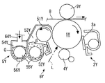
図1に示すように、画像形成装置本体100の上方にあるトナー容器収容部70には、各色(イエロー、マゼンタ、シアン、ブラック)に対応した4つのトナー容器32Y、32M、32C、32Kが着脱自在(交換自在)に設置されている(図3、図4、図42をも参照できる。)。
トナー容器収容部70の下方には中間転写ユニット15が配設されている。その中間転写ユニット15の中間転写ベルト8に対向するように、各色(イエロー、マゼンタ、シアン、ブラック)に対応した作像部6Y、6M、6C、6Kが並設されている。
トナー容器32Y、32M、32C、32Kの下方には、それぞれ、トナー補給装置60Y、60M、60C、60Kが配設されている。そして、トナー容器32Y、32M、32C、32Kに収容されたトナーは、それぞれ、トナー補給装置60Y、60M、60C、60Kによって、作像部6Y、6M、6C、6Kの現像装置内に供給(補給)される。
Embodiment 1 FIG.
1 to 50, the first embodiment of the present invention will be described in detail.
First, the configuration and operation of the entire image forming apparatus will be described.
As shown in FIG. 1, four toner containers 32Y, 32M, 32C, and 32K corresponding to the respective colors (yellow, magenta, cyan, and black) are attached to and detached from the toner container housing portion 70 above the image forming apparatus main body 100. It is installed freely (changeable) (see also FIGS. 3, 4 and 42).
An intermediate transfer unit 15 is disposed below the toner container housing portion 70. Image forming portions 6Y, 6M, 6C, and 6K corresponding to the respective colors (yellow, magenta, cyan, and black) are arranged in parallel so as to face the intermediate transfer belt 8 of the intermediate transfer unit 15.
Below the toner containers 32Y, 32M, 32C, and 32K, toner replenishing devices 60Y, 60M, 60C, and 60K are disposed, respectively. The toners stored in the toner containers 32Y, 32M, 32C, and 32K are supplied (supplemented) into the developing devices of the image forming units 6Y, 6M, 6C, and 6K by the toner replenishing devices 60Y, 60M, 60C, and 60K, respectively. )

図2を参照して、イエローに対応した作像部6Yは、感光体ドラム1Yと、感光体ドラム1Yの周囲に配設された帯電部4Y、現像装置5Y(現像部)、クリーニング部2Y、除電部(不図示である。)、等で構成されている。そして、感光体ドラム1Y上で、作像プロセス(帯電工程、露光工程、現像工程、転写工程、クリーニング工程)がおこなわれて、感光体ドラム1Y上にイエロー画像が形成されることになる。   Referring to FIG. 2, an image forming unit 6Y corresponding to yellow includes a photosensitive drum 1Y, a charging unit 4Y disposed around the photosensitive drum 1Y, a developing device 5Y (developing unit), a cleaning unit 2Y, It is comprised by the static elimination part (not shown) etc. Then, an image forming process (charging process, exposure process, developing process, transfer process, cleaning process) is performed on the photosensitive drum 1Y, and a yellow image is formed on the photosensitive drum 1Y.

なお、他の3つの作像部6M、6C、6Kも、使用されるトナーの色が異なる以外は、イエローに対応した作像部6Yとほぼ同様の構成となっていて、それぞれのトナー色に対応した画像が形成される。以下、他の3つの作像部6M、6C、6Kの説明を適宜に省略して、イエローに対応した作像部6Yのみの説明をおこなうことにする。   The other three image forming units 6M, 6C, and 6K have substantially the same configuration as that of the image forming unit 6Y corresponding to yellow except that the color of the toner used is different. A corresponding image is formed. Hereinafter, description of the other three image forming units 6M, 6C, and 6K will be omitted as appropriate, and only the image forming unit 6Y corresponding to yellow will be described.

図2を参照して、感光体ドラム1Yは、不図示の駆動モータによって図2中の時計方向に回転駆動される。そして、帯電部4Yの位置で、感光体ドラム1Yの表面が一様に帯電される(帯電工程である。)。
その後、感光体ドラム1Yの表面は、露光装置7(図1を参照できる。)から発せられたレーザ光Lの照射位置に達して、この位置での露光走査によってイエローに対応した静電潜像が形成される(露光工程である。)。
Referring to FIG. 2, the photosensitive drum 1Y is driven to rotate clockwise in FIG. 2 by a drive motor (not shown). Then, the surface of the photosensitive drum 1Y is uniformly charged at the position of the charging unit 4Y (a charging process).
After that, the surface of the photosensitive drum 1Y reaches the irradiation position of the laser beam L emitted from the exposure device 7 (see FIG. 1), and the electrostatic latent image corresponding to yellow by exposure scanning at this position. Is formed (this is an exposure step).

その後、感光体ドラム1Yの表面は、現像装置5Yとの対向位置に達して、この位置で静電潜像が現像されて、イエローのトナー像が形成される(現像工程である。)。
その後、感光体ドラム1Yの表面は、中間転写ベルト8及び第1転写バイアスローラ9Yとの対向位置に達して、この位置で感光体ドラム1Y上のトナー像が中間転写ベルト8上に転写される(1次転写工程である。)。このとき、感光体ドラム1Y上には、僅かながら未転写トナーが残存する。
Thereafter, the surface of the photosensitive drum 1Y reaches a position facing the developing device 5Y, and the electrostatic latent image is developed at this position to form a yellow toner image (developing process).
Thereafter, the surface of the photosensitive drum 1Y reaches a position facing the intermediate transfer belt 8 and the first transfer bias roller 9Y, and the toner image on the photosensitive drum 1Y is transferred onto the intermediate transfer belt 8 at this position. (This is a primary transfer step.) At this time, a small amount of untransferred toner remains on the photosensitive drum 1Y.

その後、感光体ドラム1Yの表面は、クリーニング部2Yとの対向位置に達して、この位置で感光体ドラム1Y上に残存した未転写トナーがクリーニングブレード2aによって機械的に回収される(クリーニング工程である。)。
最後に、感光体ドラム1Yの表面は、不図示の除電部との対向位置に達して、この位置で感光体ドラム1Y上の残留電位が除去される。
こうして、感光体ドラム1Y上でおこなわれる、一連の作像プロセスが終了する。
Thereafter, the surface of the photosensitive drum 1Y reaches a position facing the cleaning unit 2Y, and untransferred toner remaining on the photosensitive drum 1Y at this position is mechanically collected by the cleaning blade 2a (in the cleaning process). is there.).
Finally, the surface of the photosensitive drum 1Y reaches a position facing a neutralization unit (not shown), and the residual potential on the photosensitive drum 1Y is removed at this position.
Thus, a series of image forming processes performed on the photosensitive drum 1Y is completed.

なお、上述した作像プロセスは、他の作像部6M、6C、6Kでも、イエロー作像部6Yと同様におこなわれる。すなわち、作像部の下方に配設された露光部7から、画像情報に基いたレーザ光Lが、各作像部6M、6C、6Kの感光体ドラム上に向けて照射される。詳しくは、露光部7は、光源からレーザ光Lを発して、そのレーザ光Lを回転駆動されたポリゴンミラーで走査しながら、複数の光学素子を介して感光体ドラム上に照射する。
その後、現像工程を経て各感光体ドラム上に形成した各色のトナー像を、中間転写ベルト8上に重ねて転写する。こうして、中間転写ベルト8上にカラー画像が形成される。
The image forming process described above is performed in the other image forming units 6M, 6C, and 6K in the same manner as the yellow image forming unit 6Y. That is, the laser beam L based on the image information is emitted from the exposure unit 7 disposed below the image forming unit onto the photosensitive drums of the image forming units 6M, 6C, and 6K. Specifically, the exposure unit 7 emits laser light L from a light source, and irradiates the photosensitive drum through a plurality of optical elements while scanning the laser light L with a polygon mirror that is rotationally driven.
Thereafter, the toner images of the respective colors formed on the respective photosensitive drums through the developing process are transferred onto the intermediate transfer belt 8 in an overlapping manner. In this way, a color image is formed on the intermediate transfer belt 8.

ここで、図1を参照して、中間転写ユニット15は、中間転写ベルト8、4つの1次転写バイアスローラ9Y、9M、9C、9K、2次転写バックアップローラ12、複数のテンションローラ、中間転写クリーニング部、等で構成される。中間転写ベルト8は、複数のローラ部材によって張架・支持されるとともに、1つのローラ部材12の回転駆動によって図1中の矢印方向に無端移動される。   Here, referring to FIG. 1, the intermediate transfer unit 15 includes an intermediate transfer belt 8, four primary transfer bias rollers 9Y, 9M, 9C, 9K, a secondary transfer backup roller 12, a plurality of tension rollers, and an intermediate transfer. It consists of a cleaning unit, etc. The intermediate transfer belt 8 is stretched and supported by a plurality of roller members, and is endlessly moved in the direction of the arrow in FIG.

4つの1次転写バイアスローラ9Y、9M、9C、9Kは、それぞれ、中間転写ベルト8を感光体ドラム1Y、1M、1C、1Kとの間に挟み込んで1次転写ニップを形成している。そして、1次転写バイアスローラ9Y、9M、9C、9Kに、トナーの極性とは逆の転写バイアスが印加される。
そして、中間転写ベルト8は、矢印方向に走行して、各1次転写バイアスローラ9Y、9M、9C、9Kの1次転写ニップを順次通過する。こうして、感光体ドラム1Y、1M、1C、1K上の各色のトナー像が、中間転写ベルト8上に重ねて1次転写される。
The four primary transfer bias rollers 9Y, 9M, 9C, and 9K respectively sandwich the intermediate transfer belt 8 with the photosensitive drums 1Y, 1M, 1C, and 1K to form a primary transfer nip. Then, a transfer bias reverse to the polarity of the toner is applied to the primary transfer bias rollers 9Y, 9M, 9C, and 9K.
The intermediate transfer belt 8 travels in the direction of the arrow and sequentially passes through the primary transfer nips of the primary transfer bias rollers 9Y, 9M, 9C, and 9K. In this way, the toner images of the respective colors on the photosensitive drums 1Y, 1M, 1C, and 1K are primarily transferred while being superimposed on the intermediate transfer belt 8.

その後、各色のトナー像が重ねて転写された中間転写ベルト8は、2次転写ローラ19との対向位置に達する。この位置では、2次転写バックアップローラ12が、2次転写ローラ19との間に中間転写ベルト8を挟み込んで2次転写ニップを形成している。そして、中間転写ベルト8上に形成された4色のトナー像は、この2次転写ニップの位置に搬送された転写紙等の記録媒体P上に転写される。このとき、中間転写ベルト8には、記録媒体Pに転写されなかった未転写トナーが残存する。   Thereafter, the intermediate transfer belt 8 on which the toner images of the respective colors are transferred in a superimposed manner reaches a position facing the secondary transfer roller 19. At this position, the secondary transfer backup roller 12 sandwiches the intermediate transfer belt 8 with the secondary transfer roller 19 to form a secondary transfer nip. The four-color toner images formed on the intermediate transfer belt 8 are transferred onto a recording medium P such as transfer paper conveyed to the position of the secondary transfer nip. At this time, untransferred toner that has not been transferred to the recording medium P remains on the intermediate transfer belt 8.

その後、中間転写ベルト8は、中間転写クリーニング部(不図示である。)の位置に達する。そして、この位置で、中間転写ベルト8上の未転写トナーが回収される。
こうして、中間転写ベルト8上でおこなわれる、一連の転写プロセスが終了する。
Thereafter, the intermediate transfer belt 8 reaches the position of an intermediate transfer cleaning unit (not shown). At this position, the untransferred toner on the intermediate transfer belt 8 is collected.
Thus, a series of transfer processes performed on the intermediate transfer belt 8 is completed.

ここで、2次転写ニップの位置に搬送された記録媒体Pは、装置本体100の下方に配設された給紙部26から、給紙ローラ27やレジストローラ対28等を経由して搬送されたものである。
詳しくは、給紙部26には、転写紙等の記録媒体Pが複数枚重ねて収納されている。そして、給紙ローラ27が図1中の反時計方向に回転駆動されると、一番上の記録媒体Pがレジストローラ対28のローラ間に向けて給送される。
Here, the recording medium P transported to the position of the secondary transfer nip is transported from a paper feeding unit 26 disposed below the apparatus main body 100 via a paper feeding roller 27, a registration roller pair 28, and the like. It is a thing.
Specifically, a plurality of recording media P such as transfer paper are stored in the paper supply unit 26 in a stacked manner. When the paper feed roller 27 is driven to rotate counterclockwise in FIG. 1, the uppermost recording medium P is fed toward the rollers of the registration roller pair 28.

レジストローラ対28に搬送された記録媒体Pは、回転駆動を停止したレジストローラ対28のローラニップの位置で一旦停止する。そして、中間転写ベルト8上のカラー画像にタイミングを合わせて、レジストローラ対28が回転駆動されて、記録媒体Pが2次転写ニップに向けて搬送される。こうして、記録媒体P上に、所望のカラー画像が転写される。   The recording medium P transported to the registration roller pair 28 temporarily stops at the position of the roller nip of the registration roller pair 28 whose rotation drive has been stopped. Then, the registration roller pair 28 is rotationally driven in synchronization with the color image on the intermediate transfer belt 8, and the recording medium P is conveyed toward the secondary transfer nip. In this way, a desired color image is transferred onto the recording medium P.

その後、2次転写ニップの位置でカラー画像が転写された記録媒体Pは、定着部20の位置に搬送される。そして、この位置で、定着ベルト及び加圧ローラによる熱と圧力とにより、表面に転写されたカラー画像が記録媒体P上に定着される。
その後、記録媒体Pは、排紙ローラ対29のローラ間を経て、装置外へと排出される。排紙ローラ対29によって装置外に排出された被転写Pは、出力画像として、スタック部30上に順次スタックされる。
こうして、画像形成装置における、一連の画像形成プロセスが完了する。
Thereafter, the recording medium P on which the color image is transferred at the position of the secondary transfer nip is conveyed to the position of the fixing unit 20. At this position, the color image transferred to the surface is fixed on the recording medium P by heat and pressure generated by the fixing belt and the pressure roller.
Thereafter, the recording medium P is discharged to the outside of the apparatus through the rollers of the discharge roller pair 29. The transferred P discharged from the apparatus by the discharge roller pair 29 is sequentially stacked on the stack unit 30 as an output image.
Thus, a series of image forming processes in the image forming apparatus is completed.

次に、図2にて、作像部における現像装置の構成・動作について、さらに詳しく説明する。
現像装置5Yは、感光体ドラム1Yに対向する現像ローラ51Y、現像ローラ51Yに対向するドクターブレード52Y、現像剤収容部53Y、54Y内に配設された2つの搬送スクリュ55Y、現像剤中のトナー濃度を検知する濃度検知センサ56Y、等で構成される。現像ローラ51Yは、内部に固設されたマグネットや、マグネットの周囲を回転するスリーブ等で構成される。現像剤収容部53Y、54Y内には、キャリアとトナーとからなる2成分現像剤Gが収容されている。現像剤収容部54Yは、その上方に形成された開口を介してトナー落下搬送経路64Yに連通している。
Next, the configuration and operation of the developing device in the image forming unit will be described in more detail with reference to FIG.
The developing device 5Y includes a developing roller 51Y facing the photosensitive drum 1Y, a doctor blade 52Y facing the developing roller 51Y, two conveying screws 55Y disposed in the developer accommodating portions 53Y and 54Y, and toner in the developer. Consists of a density detection sensor 56Y for detecting density. The developing roller 51Y includes a magnet fixed inside, a sleeve rotating around the magnet, and the like. In the developer accommodating portions 53Y and 54Y, a two-component developer G composed of a carrier and a toner is accommodated. The developer accommodating portion 54Y communicates with the toner dropping conveyance path 64Y through an opening formed thereabove.

このように構成された現像装置5Yは、次のように動作する。
現像ローラ51Yのスリーブは、図2の矢印方向に回転している。そして、マグネットにより形成された磁界によって現像ローラ51Y上に担持された現像剤Gは、スリーブの回転にともない現像ローラ51Y上を移動する。
The developing device 5Y configured as described above operates as follows.
The sleeve of the developing roller 51Y rotates in the direction of the arrow in FIG. The developer G carried on the developing roller 51Y by the magnetic field formed by the magnet moves on the developing roller 51Y as the sleeve rotates.

ここで、現像装置5Y内の現像剤Gは、現像剤中のトナーの割合(トナー濃度)が所定の範囲内になるように調整される。詳しくは、現像装置5Y内のトナー消費に応じて、トナー容器32Yに収容されているトナーが、トナー補給装置60Y(図3等を参照できる。)を介して現像剤収容部54Y内に補給される。なお、トナー補給装置の構成・動作については、後で詳しく説明する。   Here, the developer G in the developing device 5Y is adjusted so that the ratio of toner in the developer (toner concentration) is within a predetermined range. Specifically, according to the toner consumption in the developing device 5Y, the toner accommodated in the toner container 32Y is replenished into the developer accommodating portion 54Y via the toner replenishing device 60Y (see FIG. 3 and the like). The The configuration and operation of the toner supply device will be described in detail later.

その後、現像剤収容部54Y内に補給されたトナーは、2つの搬送スクリュ55Yによって、現像剤Gとともに混合・撹拌されながら、2つの現像剤収容部53Y、54Yを循環する(図2の紙面垂直方向の移動である。)。そして、現像剤G中のトナーは、キャリアとの摩擦帯電によりキャリアに吸着して、現像ローラ51Y上に形成された磁力によりキャリアとともに現像ローラ51Y上に担持される。   Thereafter, the toner replenished in the developer accommodating portion 54Y is circulated through the two developer accommodating portions 53Y and 54Y while being mixed and stirred together with the developer G by the two conveying screws 55Y (perpendicular to the paper surface in FIG. 2). Direction movement.) The toner in the developer G is attracted to the carrier by frictional charging with the carrier, and is carried on the developing roller 51Y together with the carrier by the magnetic force formed on the developing roller 51Y.

現像ローラ51Y上に担持された現像剤Gは、図2中の矢印方向に搬送されて、ドクターブレード52Yの位置に達する。そして、現像ローラ51Y上の現像剤Gは、この位置で現像剤量が適量化された後に、感光体ドラム1Yとの対向位置(現像領域である。)まで搬送される。そして、現像領域に形成された電界によって、感光体ドラム1Y上に形成された潜像にトナーが吸着される。その後、現像ローラ51Y上に残った現像剤Gはスリーブの回転にともない現像剤収容部53Yの上方に達して、この位置で現像ローラ51Yから離脱される。   The developer G carried on the developing roller 51Y is conveyed in the direction of the arrow in FIG. 2 and reaches the position of the doctor blade 52Y. The developer G on the developing roller 51Y is conveyed to a position facing the photosensitive drum 1Y (development region) after the developer amount is made appropriate at this position. The toner is attracted to the latent image formed on the photosensitive drum 1Y by the electric field formed in the development area. Thereafter, the developer G remaining on the developing roller 51Y reaches above the developer containing portion 53Y as the sleeve rotates, and is detached from the developing roller 51Y at this position.

次に、図3及び図4にて、トナー補給装置60Y、60M、60C、60Kについて詳述する。
図3を参照して、装置本体100のトナー容器収容部70に設置された各トナー容器32Y、32M、32C、32K内のトナーは、各色の現像装置内のトナー消費に応じて、トナー色ごとに設けられたトナー補給装置60Y、60M、60C、60Kによって適宜に各現像装置内に補給される。
なお、4つのトナー補給装置60Y、60M、60C、60Kやトナー容器32Y、32M、32C、32Kは、作像プロセスに用いられるトナーの色が異なる以外はほぼ同一構造であるので、イエローに対応したトナー補給装置50Yやトナー容器32Yのみの説明をおこない、他の3つの色に対応したトナー補給装置60M、60C、60Kやトナー容器32M、32C、32Kの説明を適宜に省略する。
Next, the toner supply devices 60Y, 60M, 60C, and 60K will be described in detail with reference to FIGS.
Referring to FIG. 3, the toner in each of the toner containers 32Y, 32M, 32C, 32K installed in the toner container accommodating portion 70 of the apparatus main body 100 is separated for each toner color in accordance with the toner consumption in each color developing device. Each developing device is appropriately replenished by toner replenishing devices 60Y, 60M, 60C, and 60K provided on the developing device.
The four toner replenishing devices 60Y, 60M, 60C, and 60K and the toner containers 32Y, 32M, 32C, and 32K have substantially the same structure except for the color of the toner used in the image forming process, and therefore correspond to yellow. Only the toner supply device 50Y and the toner container 32Y will be described, and descriptions of the toner supply devices 60M, 60C, and 60K and the toner containers 32M, 32C, and 32K corresponding to the other three colors will be omitted as appropriate.

図4に示すように、トナー容器32Y、32M、32C、32Kが装置本体100のトナー容器収容部70に装着(矢印Q方向の移動である。)されると、その装着動作に連動して、トナー容器32Y、32M、32C、32Kのシャッタ部材34dが移動してトナー排出口Wが開放されるとともに、トナー補給装置32Y、32M、32C、32Kのトナー補給口73w(図3、図42を参照できる。)とトナー排出口Wとが連通する。これにより、トナー容器32Y、32M、32C、32K内に収容されたトナーが、トナー排出口Wから排出されて、トナー補給装置60Y、60M、60C、60Kのトナー補給口73wからトナータンク部61Y内に貯溜されることになる。
ここで、図3の模式図を参照して、トナー容器32Yは、略円筒状のトナーボトルであって、主として、トナー容器収容部70に非回転で保持されるキャップ部34Yと、ギア33cが一体的に形成された容器本体33Y(ボトル本体)と、で構成される。容器本体33Yは、キャップ部34Yに対して相対的に回転可能に保持されていて、駆動部91(駆動モータ、駆動ギア81等で構成されている。)によって図3の矢印方向に回転駆動される。そして、容器本体33Y自体が回転することで、容器本体33Yの内周面に螺旋状に形成された突起33bによって、トナー容器32Y(容器本体33Y)の内部に収容されたトナーが長手方向に搬送されて(図3の左方から右方への搬送である。)、キャップ部34Yのトナー排出口Wからトナーが排出される。すなわち、駆動部91によってトナー容器32Yの容器本体33Yが適宜に回転駆動されることで、トナータンク部61Yにトナーが適宜に供給される。なお、トナー容器32Y、32M、32C、32Kは、それぞれ、寿命に達したとき(収容するトナーがほとんどすべて消費されて空になったときである。)に新品のものに交換される。
As shown in FIG. 4, when the toner containers 32Y, 32M, 32C, and 32K are attached to the toner container accommodating portion 70 of the apparatus main body 100 (moving in the direction of the arrow Q), in conjunction with the attaching operation, The shutter member 34d of the toner containers 32Y, 32M, 32C, and 32K moves to open the toner discharge port W, and the toner supply port 73w of the toner supply devices 32Y, 32M, 32C, and 32K (see FIGS. 3 and 42). And the toner discharge port W communicate with each other. As a result, the toner accommodated in the toner containers 32Y, 32M, 32C, and 32K is discharged from the toner discharge port W, and is transferred from the toner supply port 73w of the toner supply devices 60Y, 60M, 60C, and 60K into the toner tank portion 61Y. Will be stored.
Here, referring to the schematic diagram of FIG. 3, the toner container 32 </ b> Y is a substantially cylindrical toner bottle. And an integrally formed container body 33Y (bottle body). The container body 33Y is rotatably held relative to the cap portion 34Y, and is rotationally driven in the direction of the arrow in FIG. 3 by a drive unit 91 (comprising a drive motor, a drive gear 81, etc.). The As the container body 33Y itself rotates, the toner contained in the toner container 32Y (container body 33Y) is conveyed in the longitudinal direction by the protrusions 33b formed in a spiral shape on the inner peripheral surface of the container body 33Y. Then, the toner is discharged from the toner discharge port W of the cap portion 34Y (conveying from the left to the right in FIG. 3). That is, when the container main body 33Y of the toner container 32Y is appropriately rotated by the drive unit 91, the toner is appropriately supplied to the toner tank unit 61Y. The toner containers 32Y, 32M, 32C, and 32K are replaced with new ones when they reach the end of their lives (when almost all the toner to be stored is consumed and emptied).

図3を参照して、トナー補給装置60Y、60M、60C、60Kは、トナー容器収容部70、トナータンク部61Y、トナー搬送スクリュ62Y、撹拌部材65Y、トナーエンドセンサ66Y、駆動部91、等で構成されている。
トナータンク部61Yは、トナー容器32Yのトナー排出口Wの下方に配設されていて、トナー容器32Yのトナー排出口Wから排出されたトナーが貯留される。トナータンク部61Yの底部は、トナー搬送スクリュ62Yの上流部に接続されている。
また、トナータンク部61Yの壁面(底部から所定高さの位置である。)には、トナータンク部61Yに貯留されたトナーが所定量以下になったことを検知するトナーエンドセンサ66Yが設置されている。トナーエンドセンサ66Yとしては、圧電センサ等を用いることができる。そして、トナーエンドセンサ66Yによってトナータンク部61Yに貯留されたトナーが所定量以下になったことが制御部70にて検知(トナーエンド検知)されると、制御部70の制御により駆動部91(駆動ギア81)によってトナー容器32Yの容器本体33Yを所定時間回転駆動してトナータンク部61Yへのトナー補給をおこなう。さらに、このような制御を繰り返してもトナーエンドセンサ66Yによるトナーエンド検知が解除されない場合には、トナー容器32Y内にトナーがないものとして、装置本体100の表示部(不図示である。)にトナー容器32Yの交換を促す旨の表示をおこなう。
Referring to FIG. 3, toner replenishing devices 60Y, 60M, 60C, and 60K include a toner container housing portion 70, a toner tank portion 61Y, a toner transport screw 62Y, a stirring member 65Y, a toner end sensor 66Y, a driving portion 91, and the like. It is configured.
The toner tank 61Y is disposed below the toner discharge port W of the toner container 32Y, and stores toner discharged from the toner discharge port W of the toner container 32Y. The bottom of the toner tank 61Y is connected to the upstream part of the toner conveying screw 62Y.
Further, a toner end sensor 66Y that detects that the amount of toner stored in the toner tank 61Y has become a predetermined amount or less is installed on the wall surface of the toner tank 61Y (position at a predetermined height from the bottom). ing. A piezoelectric sensor or the like can be used as the toner end sensor 66Y. When the control unit 70 detects that the amount of toner stored in the toner tank unit 61Y has become equal to or less than a predetermined amount by the toner end sensor 66Y (toner end detection), the control unit 70 controls the drive unit 91 ( The drive gear 81) rotates the container body 33Y of the toner container 32Y for a predetermined time to supply toner to the toner tank portion 61Y. Further, if the toner end detection by the toner end sensor 66Y is not canceled even after such control is repeated, it is assumed that there is no toner in the toner container 32Y and is displayed on the display unit (not shown) of the apparatus main body 100. A message to prompt the user to replace the toner container 32Y is displayed.

また、トナータンク部61Yの中央(トナーエンドセンサ66Yの近傍である。)には、トナータンク部61Yに貯留されたトナーの凝集を防ぐ撹拌部材65Yが設置されている。撹拌部材65Yは、軸部に可撓性部材が設置されたものであって、図3の時計方向に回転することによりトナータンク部61Y内のトナーを撹拌する。さらに、撹拌部材65Yの可撓性部材の先端が、回転周期でトナーエンドセンサ66Yの検知面に摺接することで、トナーエンドセンサ66Yの検知面にトナーが固着して検知精度が低下する不具合を抑止している。   In addition, a stirring member 65Y that prevents aggregation of the toner stored in the toner tank 61Y is installed at the center of the toner tank 61Y (in the vicinity of the toner end sensor 66Y). The agitating member 65Y is provided with a flexible member at the shaft portion, and agitates the toner in the toner tank portion 61Y by rotating clockwise in FIG. Further, the tip of the flexible member of the stirring member 65Y is in sliding contact with the detection surface of the toner end sensor 66Y at a rotation cycle, so that the toner adheres to the detection surface of the toner end sensor 66Y and the detection accuracy decreases. Suppressed.

図示は省略するが、トナー搬送スクリュ62Yは、トナータンク部61Yに貯留されたトナーを斜め上方に搬送するものである。詳しくは、トナー搬送スクリュ62Yは、トナータンク部61Yの底部(最下点)から現像装置5Yの上方に向けてトナーを直線的に搬送する。そして、トナー搬送スクリュ62Yによって搬送されたトナーは、トナー落下搬送経路64Y(図2を参照できる。)を自重落下して現像装置5Y(現像剤収容部54Y)内に補給される。   Although illustration is omitted, the toner conveying screw 62Y conveys the toner stored in the toner tank portion 61Y obliquely upward. Specifically, the toner transport screw 62Y linearly transports the toner from the bottom (lowermost point) of the toner tank 61Y toward the upper side of the developing device 5Y. Then, the toner transported by the toner transport screw 62Y falls in its own weight on the toner drop transport path 64Y (see FIG. 2) and is replenished into the developing device 5Y (developer container 54Y).

また、図4を参照して、トナー容器収容部70は、主として、トナー容器32Yのキャップ部34Yを保持するためのキャップ受部73と、トナー容器32Yの容器本体33Yを保持するためのボトル受部72(容器本体受部)と、トナー容器32Yの装着動作時における挿入口となる挿入口部71と、で構成されている。なお、トナー容器収容部70(ボトル受部72、キャップ受部73)の構成については、図32〜図48を用いて後で詳しく説明する。   Referring to FIG. 4, the toner container housing portion 70 mainly includes a cap receiving portion 73 for holding the cap portion 34Y of the toner container 32Y and a bottle receiving portion for holding the container main body 33Y of the toner container 32Y. A part 72 (container main body receiving part) and an insertion port 71 serving as an insertion port during the mounting operation of the toner container 32Y are configured. The configuration of the toner container storage unit 70 (bottle receiving unit 72, cap receiving unit 73) will be described in detail later with reference to FIGS.

ここで、図1を参照して、装置本体100の手前側(図1の紙面垂直方向手前側である。)に設置された本体カバー(不図示である。)を開放すると、トナー容器収容部70(挿入口部71)が露呈される。そして、各トナー容器32Y、32M、32C、32Kの長手方向を水平方向とした状態で、装置本体100の手前側から各トナー容器32Y、32M、32C、32Kの着脱操作(トナー容器の長手方向を着脱方向とする着脱操作である。)がおこなわれる。
ここで、ボトル受部72は、その長手方向の長さが、容器本体33Yの長手方向の長さとほぼ同等になるように形成されている。また、キャップ受部73はボトル受部72における長手方向(装着方向)の一端側に設けられ、挿入口部71はボトル受部72における長手方向(装着方向)の他端側に設けられている。そのため、トナー容器32Yの装着動作にともない、キャップ部34Yは、挿入口部71を通過した後に、しばらくボトル受部72の滑動面上を滑動して、その後にキャップ受部73にセットされることになる。
Here, referring to FIG. 1, when the main body cover (not shown) installed on the front side of the apparatus main body 100 (the front side in the direction perpendicular to the paper surface of FIG. 1) is opened, the toner container housing portion. 70 (insertion port 71) is exposed. Then, with the longitudinal direction of the toner containers 32Y, 32M, 32C, and 32K set to the horizontal direction, the toner containers 32Y, 32M, 32C, and 32K can be attached and detached from the front side of the apparatus main body 100 (the longitudinal direction of the toner containers is changed). This is an attachment / detachment operation in the attachment / detachment direction.
Here, the bottle receiving portion 72 is formed so that its length in the longitudinal direction is substantially equal to the length in the longitudinal direction of the container body 33Y. The cap receiving portion 73 is provided on one end side in the longitudinal direction (mounting direction) of the bottle receiving portion 72, and the insertion port portion 71 is provided on the other end side in the longitudinal direction (mounting direction) of the bottle receiving portion 72. . Therefore, in accordance with the mounting operation of the toner container 32Y, the cap part 34Y slides on the sliding surface of the bottle receiving part 72 for a while after passing through the insertion port part 71, and is then set on the cap receiving part 73. become.

また、本実施の形態1では、トナー容器32Y、32M、32C、32Kが着脱自在に並設される、トナー容器収容部70のキャップ受部73に、アンテナ73e(RFID用アンテナ)が設置されている(図38、図39等を参照できる。)。詳しくは、アンテナ73eは、トナー容器32Yのキャップ部34Yの端面に設置された電子情報格納部材としてのRFID用チップ35(図5、図9等を参照できる。)と通信をおこなうためのものである。
そして、トナー容器32Y、32M、32C、32KのRFID用チップ35(電子情報格納部材)と、装置本体100のアンテナ73e(RFID用アンテナ)と、の間で必要な情報の授受がおこなわれる。双方の間で通信される情報としては、トナー容器の製造番号、リサイクル回数等の情報や、トナーの容量、ロット番号、色等の情報や、画像形成装置本体100の使用履歴等の情報がある。RFID用チップ35(電子情報格納部材)には、これらの電子情報が画像形成装置本体100に設置される前に予め格納されている(又は、設置された後に装置本体100から受け取った情報が格納される)。
In the first embodiment, an antenna 73e (RFID antenna) is installed in the cap receiving portion 73 of the toner container housing portion 70 in which the toner containers 32Y, 32M, 32C, and 32K are detachably arranged. (See FIGS. 38 and 39). Specifically, the antenna 73e is for communicating with an RFID chip 35 (see FIGS. 5 and 9) as an electronic information storage member installed on the end surface of the cap portion 34Y of the toner container 32Y. is there.
Necessary information is exchanged between the RFID chip 35 (electronic information storage member) of the toner containers 32Y, 32M, 32C, and 32K and the antenna 73e (RFID antenna) of the apparatus main body 100. Information communicated between the two includes information such as a toner container manufacturing number and the number of recycling, information such as toner capacity, lot number and color, and information such as usage history of the image forming apparatus main body 100. . The RFID chip 35 (electronic information storage member) stores such electronic information in advance before being installed in the image forming apparatus main body 100 (or information received from the apparatus main body 100 after being installed). )

次に、図5〜図31にて、トナー容器32Y、32M、32C、32Kについて詳述する。
図5〜図7に示すように、トナー容器32Yは、主として、容器本体33Y(ボトル本体)と、その頭部に設けられたキャップ部34Y(ボトルキャップ)と、で構成される。さらに、図9を参照して、トナー容器32Yは、容器本体33Yとキャップ部34Yとの他に、撹拌部材33f、キャップシール37、シャッタ部材34d、シール部材としてのシャッタシール36、電子情報格納部材としてのRFID用チップ35等に分解される。
Next, the toner containers 32Y, 32M, 32C, and 32K will be described in detail with reference to FIGS.
As shown in FIGS. 5 to 7, the toner container 32 </ b> Y mainly includes a container main body 33 </ b> Y (bottle main body) and a cap portion 34 </ b> Y (bottle cap) provided on the head thereof. Further, referring to FIG. 9, in addition to the container main body 33Y and the cap portion 34Y, the toner container 32Y includes a stirring member 33f, a cap seal 37, a shutter member 34d, a shutter seal 36 as a seal member, and an electronic information storage member. As an RFID chip 35 or the like.

容器本体33Yの頭部には、容器本体33Yとともに一体的に回転するギア33cと、開口部Aと、が長手方向(図8紙面垂直方向である。)の一端側に設けられている(図9〜図11を参照できる。)。開口部Aは、容器本体33Yの頭部(装着動作において先方となる位置である。)に設けられていて、容器本体33Y内に収容されたトナーをキャップ部34Y内のスペース(空洞Bであって、図28を参照できる。)に向けて排出するためのものである。
なお、容器本体33Y内からキャップ部34Y内の空洞Bへのトナー搬送(容器本体33Yの回転駆動)は、キャップ部34Y内におけるトナーが所定の喫水線を下回らない程度に適宜におこなわれる。
At the head of the container body 33Y, a gear 33c that rotates integrally with the container body 33Y and an opening A are provided on one end side in the longitudinal direction (the vertical direction in FIG. 8). 9 to 11 can be referred to). The opening A is provided at the head of the container main body 33Y (the position that is the tip in the mounting operation), and allows the toner contained in the container main body 33Y to pass through the space in the cap 34Y (the cavity B). FIG. 28 can be referred to)).
The toner conveyance from the container main body 33Y to the cavity B in the cap part 34Y (rotational drive of the container main body 33Y) is appropriately performed so that the toner in the cap part 34Y does not fall below a predetermined water line.

ギア33cは、装置本体100のトナー容器収容部70に設けられた駆動ギア81と噛合して、容器本体33Yを回転軸を中心に回転駆動させるためのものである。詳しくは、ギア33cは、開口部Aの周りを1周するように形成されていて、容器本体33Yの回転軸に対して放射状に複数の歯が形成されている。そして、ギア33cは、その一部が、キャップ部34Yに形成された切欠部34x(図22等を参照できる。)から露呈して、図8における斜め下方の噛合位置で装置本体100の駆動ギア81と噛合する。そして、駆動ギア81からギア33cに駆動力が伝達されて、容器本体33Yが図8の時計方向に回転することになる。なお、本実施の形態1において、駆動ギア81及びギア33cは平歯車である。   The gear 33c is for meshing with a drive gear 81 provided in the toner container accommodating portion 70 of the apparatus main body 100 to drive the container main body 33Y about the rotation axis. Specifically, the gear 33c is formed so as to make one round around the opening A, and a plurality of teeth are formed radially with respect to the rotation axis of the container body 33Y. A part of the gear 33c is exposed from a notch part 34x (see FIG. 22 and the like) formed in the cap part 34Y, and the drive gear of the apparatus main body 100 is engaged at an obliquely lower meshing position in FIG. Mesh with 81. Then, the driving force is transmitted from the driving gear 81 to the gear 33c, and the container body 33Y rotates in the clockwise direction in FIG. In the first embodiment, the drive gear 81 and the gear 33c are spur gears.

図5及び図6を参照して、容器本体33Yの長手方向他端側(装着方向の後方の端部である。)には、トナー容器32Yの着脱作業をおこなう際にユーザーが把持するための把持部33dが設けられている。ユーザーは把持部33dを把持しながら、画像形成装置本体100に対してトナー容器32Yの装着をおこなうことになる(図5の矢印方向へのトナー容器32Yの移動である。)。   Referring to FIGS. 5 and 6, the other end in the longitudinal direction of the container main body 33Y (the rear end in the mounting direction) is for the user to hold when attaching / detaching the toner container 32Y. A gripping portion 33d is provided. The user attaches the toner container 32Y to the image forming apparatus main body 100 while grasping the grasping portion 33d (the movement of the toner container 32Y in the direction of the arrow in FIG. 5).

また、容器本体33Yの内周面には、螺旋状の突起33bが設けられている(外周面側から見ると螺旋状の溝となっている。)。この螺旋状の突起33bは、容器本体33Yを所定方向に回転駆動して開口部Aからトナーを排出するためのものである。このように構成された容器本体33Yは、その周面上に配設されるギア33cや把持部33dとともにブロー成形にて製造することができる。   Further, a spiral protrusion 33b is provided on the inner peripheral surface of the container body 33Y (a spiral groove when viewed from the outer peripheral surface side). The spiral projection 33b is for rotating and driving the container body 33Y in a predetermined direction to discharge the toner from the opening A. The container main body 33Y configured in this way can be manufactured by blow molding together with the gear 33c and the gripping portion 33d disposed on the peripheral surface thereof.

なお、図9〜図11を参照して、本実施の形態1におけるトナー容器32Yは、容器本体33Yとともに回転する撹拌部材33fがボトル口部33a(開口部A)に嵌合されている。撹拌部材33fは、キャップ部34Y内の空洞Bから容器本体33Y内に向けて延設された棒状部材である(図28をも参照できる。)。容器本体33Yの開口部Aとともに撹拌部材33fが回転することで、開口部Aからのトナー排出性が向上する。   9 to 11, in toner container 32Y according to the first embodiment, stirring member 33f that rotates together with container body 33Y is fitted into bottle opening 33a (opening A). The stirring member 33f is a rod-like member extending from the cavity B in the cap portion 34Y toward the container main body 33Y (see FIG. 28 as well). By rotating the stirring member 33f together with the opening A of the container main body 33Y, the toner discharging performance from the opening A is improved.

詳しくは、図12に示すように、撹拌部材33fは、ボトル口部33a(開口部A)に圧入される略環状の嵌合部33f2、嵌合部33f2上にて180度位相がずれた位置においてキャップ部34Y内の空洞Bに向けて起立する1対の棒状部33f1、2つの棒状部33f1の間に架設された架橋部33f3、等で構成されている。そして、このように構成された撹拌部材33fが、図11に示すように、ボトル口部33a(開口部A)に嵌合される。そして、撹拌部材33fにおける円柱状の2つの棒状部33f1が、容器本体32Yの開口部Aからキャップ部34Yの空洞Bに向けて搬送されるトナーの搬送力を適度に弱めながら、空洞B内のトナーをほぐすことになる。これにより、容器本体32Yの開口部Aからキャップ部34Yの空洞Bに向けて搬送されるトナー量が多すぎて空洞B内でトナーが詰まる不具合が軽減される。
なお、撹拌部材33fにおける2つの棒状部33f1は円柱状に形成されているために、棒状部33f1がトナー排出口W(トナー落下経路C)から著しく離れていると、棒状部33f1によってトナー排出口W(トナー落下経路C)近傍のトナーをほぐすことができなくなってしまう。したがって、図28等に示すように、棒状部33f1は、トナー排出口W(トナー落下経路C)の真上の位置まで延設されている。具体的に、棒状部33f1の先端部の長手方向の位置は、トナー排出口W(トナー落下経路C)の開口幅(図28の左右方向に広がる開口幅である。)の半分の位置を超える位置(図28の右側に延びた位置である。)となっている。
また、現像装置5Yにおけるトナー消費が少なくてトナー容器32Yからトナー補給装置に少量のトナーを補給する場合には、トナー容器32Yにおける容器本体32Yの回転駆動時間も短時間になり、容器本体32Yは1回転もしない程度の僅かな角度で回転することになる。しかし、このような場合であっても、撹拌部材33fに2つの棒状部33f1が180度位相をずらして設置されているため、いずれかの棒状部材33f1によってトナー排出口W(トナー落下経路C)近傍のトナーをほぐすことができる。
また、本実施の形態1における撹拌部材33fには、略環状の嵌合部33f2の中央を横断するように架橋部33f3が設けられているために、開口部Aの近傍においてその中心部分のトナーをほぐすことができる。
なお、本実施の形態1では、撹拌部材33fに2つの棒状部33f1を形成したが、図13に示すように撹拌部材33fに1つの棒状部33f1を形成することもできるし、図示は省略するが撹拌部材33fに3つ以上の棒状部33f1を形成することもできる。
Specifically, as shown in FIG. 12, the stirring member 33f is a substantially annular fitting portion 33f2 that is press-fitted into the bottle mouth portion 33a (opening portion A), and a position that is 180 degrees out of phase on the fitting portion 33f2. In FIG. 2, the pair of rod-shaped portions 33f that stand up toward the cavity B in the cap portion 34Y1, the bridging portion 33f3 laid between the two rod-shaped portions 33f1, and the like. And the stirring member 33f comprised in this way is fitted by the bottle mouth part 33a (opening part A), as shown in FIG. Then, the two cylindrical rod-shaped portions 33f1 in the stirring member 33f moderately weaken the conveying force of the toner conveyed from the opening A of the container main body 32Y toward the cavity B of the cap portion 34Y, while in the cavity B. You will loosen the toner. As a result, the amount of toner transported from the opening A of the container main body 32Y toward the cavity B of the cap 34Y and the toner being clogged in the cavity B is reduced.
Since the two rod-like portions 33f1 of the stirring member 33f are formed in a columnar shape, if the rod-like portion 33f1 is significantly separated from the toner discharge port W (toner dropping path C), the toner discharge port is formed by the rod-like portion 33f1. The toner in the vicinity of W (toner dropping path C) cannot be loosened. Therefore, as shown in FIG. 28 and the like, the rod-shaped portion 33f1 extends to a position directly above the toner discharge port W (toner dropping path C). Specifically, the longitudinal position of the tip of the rod-shaped portion 33f1 exceeds the half of the opening width of the toner discharge port W (toner dropping path C) (the opening width extending in the left-right direction in FIG. 28). The position (the position extending to the right side of FIG. 28).
Further, when the toner consumption in the developing device 5Y is small and a small amount of toner is replenished from the toner container 32Y to the toner replenishing device, the rotation drive time of the container main body 32Y in the toner container 32Y becomes short, and the container main body 32Y It will rotate at a slight angle that does not even make one rotation. However, even in such a case, since the two rod-like portions 33f1 are installed on the stirring member 33f with a phase difference of 180 degrees, the toner discharge port W (toner dropping path C) is caused by one of the rod-like members 33f1. The toner in the vicinity can be loosened.
Further, since the bridging portion 33f3 is provided in the stirring member 33f in the first embodiment so as to cross the center of the substantially annular fitting portion 33f2, the toner in the central portion in the vicinity of the opening A is provided. Can be loosened.
In the first embodiment, the two rod-like portions 33f1 are formed on the stirring member 33f. However, as shown in FIG. 13, one rod-like portion 33f1 can be formed on the stirring member 33f, and the illustration is omitted. However, three or more rod-shaped portions 33f1 can be formed on the stirring member 33f.

また、図9及び図10を参照して、容器本体33Yのボトル口部33aには、キャップ部34Yの爪部34j(図15、図29等を参照できる。)に係合して双方の部材33Y、34Yを接続するための嵌合部(凸部)が、外周を1周するように形成されている。このように、容器本体33Yは、キャップ部34Yに対して相対的に回転可能に嵌合されている。したがって、ギア33cは、キャップ部34Yに対して相対的に回転することになる。
また、容器本体33Yの頭部(ギア33cが形成された位置近傍である。)の内径は、トナーが収容された収容部(螺旋状の突起33bが形成された位置である。)の内径よりも小さくなるように形成されている(図28をも参照できる。)。そして、容器本体33Yの頭部には、その内周面が内部に向かってせり出すように形成された汲み上げ部(図9、図10の破線で囲んだ部分である。)が設けられている。そして、容器本体33Yの回転にともない螺旋状の突起33bによって開口部Aに向けて搬送されたトナーは、汲み上げ部(図9、図10の破線で囲んだ部分である。)によって頭部の小径部に汲み上げられる。その後、頭部の小径部に汲み上げられたトナーは、撹拌部材33fに撹拌されながら、開口部Aからキャップ部34Yの空洞Bに向けて排出される。
9 and 10, the bottle mouth portion 33a of the container main body 33Y is engaged with a claw portion 34j (see FIGS. 15, 29, etc.) of the cap portion 34Y, and both members are engaged. A fitting part (convex part) for connecting 33Y and 34Y is formed so as to make one round of the outer periphery. Thus, the container main body 33Y is fitted so as to be relatively rotatable with respect to the cap portion 34Y. Accordingly, the gear 33c rotates relative to the cap portion 34Y.
In addition, the inner diameter of the head of the container body 33Y (near the position where the gear 33c is formed) is larger than the inner diameter of the container (the position where the spiral protrusion 33b is formed) in which the toner is stored. (See also FIG. 28). And the pumping part (it is the part enclosed with the broken line of FIG. 9, FIG. 10) formed so that the internal peripheral surface may protrude toward the inside is provided in the head of the container main body 33Y. The toner conveyed toward the opening A by the spiral projection 33b with the rotation of the container body 33Y is the small diameter of the head by the pumping portion (the portion surrounded by the broken line in FIGS. 9 and 10). It is pumped up to the club. Thereafter, the toner pumped to the small diameter portion of the head is discharged from the opening A toward the cavity B of the cap portion 34Y while being stirred by the stirring member 33f.

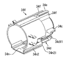
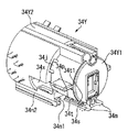
図14〜図17を参照して、トナー容器32Yのキャップ部34Yには、シャッタ部材34d、シャッタシール36(シール部材)、キャップシール37、RFID用チップ35(電子情報格納部材)、等が設置される。
キャップ部34Yは、空洞Bよりも大きな内径を有するように形成された内挿部34z(図29を参照できる。)に、容器本体33Yの開口部Aが内挿される。図20、図28等を参照して、キャップ部34Yの底部には、容器本体33Yの開口部Aから排出されたトナーを容器外であって鉛直方向下方に排出(自重落下)させるためのトナー排出口Wが形成されている。そして、キャップ部34Yの底部には、トナー排出口Wの開閉をおこなうためのシャッタ部材34dが、スライド移動可能に保持されている。具体的に、シャッタ部材34Yは、キャップ部34Yの側から容器本体33Yの側への長手方向の相対的な移動(図28の左方への移動である。)によりトナー排出口Wを開放して、容器本体33Yの側からキャップ部34Yの側への長手方向の相対的な移動(図28の右方への移動である。)によりトナー排出口Wを閉鎖する。シャッタ部材34dの開閉動作(トナー排出口Wの開閉動作である。)は、トナー容器収容部70(装置本体100)へのトナー容器32Yの長手方向の着脱動作に連動しておこなわれる。
なお、図18〜図20は、シャッタ部材34dがトナー排出口Wの開放を開始してから開放が完了するまでの動作を示すものである。また、図21は、そのときのシャッタ部材34d(シャッタ変形部34d2)の開放動作を示す模式図である。
Referring to FIGS. 14 to 17, a cap member 34Y of the toner container 32Y is provided with a shutter member 34d, a shutter seal 36 (seal member), a cap seal 37, an RFID chip 35 (electronic information storage member), and the like. Is done.
The opening A of the container body 33Y is inserted into an insertion part 34z (see FIG. 29) formed so that the cap part 34Y has an inner diameter larger than that of the cavity B. Referring to FIG. 20, FIG. 28, etc., the bottom of cap 34Y has toner for discharging (falling its own weight) the toner discharged from opening A of container main body 33Y downward in the vertical direction outside the container. A discharge port W is formed. A shutter member 34d for opening and closing the toner discharge port W is slidably held at the bottom of the cap portion 34Y. Specifically, the shutter member 34Y opens the toner discharge port W by the relative movement in the longitudinal direction from the cap portion 34Y side to the container body 33Y side (movement to the left in FIG. 28). Thus, the toner discharge port W is closed by the relative movement in the longitudinal direction from the container main body 33Y side to the cap portion 34Y side (the movement to the right in FIG. 28). The opening / closing operation of the shutter member 34d (the opening / closing operation of the toner discharge port W) is performed in conjunction with the attaching / detaching operation of the toner container 32Y in the longitudinal direction with respect to the toner container housing portion 70 (device main body 100).
18 to 20 show the operation from when the shutter member 34d starts to open the toner discharge port W to when the opening is completed. FIG. 21 is a schematic diagram showing the opening operation of the shutter member 34d (shutter deforming portion 34d2) at that time.

図14、図15等を参照して、キャップ部34Yの上部(天井部)には、長手方向に直交するキャップ部34Yの端面から長手方向に延設された第1の穴部34aが形成されている。この第1の穴部34aは、画像形成装置本体100におけるキャップ部34Yの位置決め主基準となる。詳しくは、トナー容器収容部70へのトナー容器32Yの長手方向の装着動作に連動して、キャップ部34Yの第1の穴部34aがキャップ受部73の主基準ピン73a(図39、図40等を参照できる。)に係合する。
また、キャップ部34Yの下部(底部)には、長手方向に直交するキャップ部34Yの端面から長手方向に延設された第2の穴部34bが、トナー排出口Wの位置に達しないように形成されている。この第2の穴部34bは、画像形成装置本体100におけるキャップ部34Yの位置決め従基準となる。詳しくは、トナー容器収容部70へのトナー容器32Yの長手方向の装着動作に連動して、キャップ部34Yの第2の穴部34bがキャップ受部73の従基準ピン73b(図39、図40等を参照できる。)に係合する。なお、第2の穴部34bは、図8に示すように、鉛直方向を長手方向(この「長手方向」は、その他で記載しているトナー容器32Yの「長手方向」の意味とは異なる。)とする長穴である。
このように構成された2つの穴部34a、34bによって、トナー容器収容部70におけるキャップ部34Yの位置決めがおこなわれる。また、図8を参照して、長手方向に直交する平面でみたときに、第1の穴部34aの中心を通る仮想垂線と、第2の穴部34bの中心を通る仮想垂線と、は、同一直線であるとともに、キャップ部34Yの円中心を通るように形成されている。
Referring to FIGS. 14, 15 and the like, a first hole 34a extending in the longitudinal direction from the end surface of the cap part 34Y orthogonal to the longitudinal direction is formed in the upper part (ceiling part) of the cap part 34Y. ing. The first hole portion 34a serves as a main positioning reference for the cap portion 34Y in the image forming apparatus main body 100. Specifically, in conjunction with the operation of mounting the toner container 32Y in the toner container housing part 70 in the longitudinal direction, the first hole 34a of the cap part 34Y is connected to the main reference pin 73a of the cap receiving part 73 (FIGS. 39 and 40). Etc.).
The second hole 34b extending in the longitudinal direction from the end surface of the cap 34Y orthogonal to the longitudinal direction does not reach the position of the toner discharge port W at the lower part (bottom) of the cap 34Y. Is formed. The second hole 34b serves as a positioning reference for the cap 34Y in the image forming apparatus main body 100. Specifically, the second hole 34b of the cap portion 34Y is connected to the slave reference pin 73b of the cap receiving portion 73 (FIGS. 39 and 40) in conjunction with the operation of mounting the toner container 32Y in the toner container housing portion 70 in the longitudinal direction. Etc.). As shown in FIG. 8, the second hole 34b has a vertical direction in the longitudinal direction (this "longitudinal direction" is different from the meaning of the "longitudinal direction" of the toner container 32Y described elsewhere. ).
Positioning of the cap part 34Y in the toner container housing part 70 is performed by the two holes 34a and 34b configured as described above. Also, referring to FIG. 8, when viewed in a plane orthogonal to the longitudinal direction, the virtual perpendicular passing through the center of the first hole 34a and the virtual perpendicular passing through the center of the second hole 34b are: It is the same straight line and is formed so as to pass through the center of the circle of the cap part 34Y.

ここで、図28等を参照して、第1の穴部34aの穴の深さ(又は、主基準ピン73aの長手方向の長さ)は、第2の穴部34bの穴の深さ(又は、従基準ピン73bの長手方向の長さ)よりも長く設定されている。これにより、トナー容器収容部70(キャップ受部73)へのトナー容器32Yの長手方向の装着動作において、位置決め主基準となる第1の穴部34aへの主基準ピン73aの係合が開始された後に、位置決め従基準となる第2の穴部34bへの従基準ピン73bの係合が開始されることになり、トナー容器収容部70(キャップ受部73)へのトナー容器32Yのスムーズな装着が可能になる。また、このように長手方向に長い第1の穴部34aは、キャップ部34Yの天井部(トナーに埋没することがない部分である。)に設けられているために、キャップ部34Y内におけるトナーの搬送性(流動性)に与える影響が生じないことになる。また、長手方向に短い第2の穴部34bは、キャップ部34Yの底部に設けられているものの、キャップ部34Yの端面からトナー排出口Wの位置までの短いスペースを利用して設置できるものであって、位置決め従基準としての機能を充分に発揮する。   Here, referring to FIG. 28 and the like, the depth of the hole of the first hole 34a (or the length in the longitudinal direction of the main reference pin 73a) is the depth of the hole of the second hole 34b ( Alternatively, it is set to be longer than the longitudinal length of the secondary reference pin 73b. Thereby, in the mounting operation in the longitudinal direction of the toner container 32Y to the toner container housing part 70 (cap receiving part 73), the engagement of the main reference pin 73a with the first hole 34a serving as the positioning main reference is started. After that, the engagement of the slave reference pin 73b with the second hole 34b serving as the positioning slave reference is started, and the toner container 32Y smoothly engages with the toner container housing portion 70 (cap receiving portion 73). Can be installed. In addition, since the first hole portion 34a that is long in the longitudinal direction is provided in the ceiling portion of the cap portion 34Y (a portion that is not buried in the toner), the toner in the cap portion 34Y. There will be no effect on the transportability (fluidity). The second hole 34b that is short in the longitudinal direction can be installed using a short space from the end surface of the cap 34Y to the position of the toner discharge port W, although it is provided at the bottom of the cap 34Y. Therefore, it fully functions as a positioning reference.

また、図14〜図17等を参照して、キャップ部34Yの天井部には、画像形成装置本体100(キャップ受部73)におけるキャップ部34Yの長手方向に直交する水平方向の姿勢を規制する規制部としての第1係合部34e及び第2係合部34fが形成されている。第1係合部34eと第2係合部34fとは、いずれも、長手方向に直交する断面(図8の正面図に平行する断面である。)でみたときに第1の穴部34aの穴中心を通る仮想垂線に対して線対称形となるようにキャップ部34Yの外周面から鉛直方向上方に突出するとともに、長手方向(図8の紙面垂直方向である。)に延設されている。そして、第1係合部34eと第2係合部34fとが、図38等に示すキャップ受部73の被係合部73m(凸部)に係合して、キャップ部34Yの水平方向の姿勢が規制されながらキャップ受部73に対してキャップ部34Yが着脱されるとともに、キャップ受部73にキャップ部34Yが装着された状態でのキャップ部34Yの水平方向の姿勢が規制される。
さらに詳しくは、第1係合部34e(規制部)は、第1の穴部34aの真上に形成されていて、長手方向に直交する断面でみたときに略矩形状の断面を有する。また、第1係合部34eは、第1の穴部34aの端面に対して長手方向(装着方向)に突出する突出部34e1が形成されている。この突出部34e1の先端は、図14等に示すように、テーパ状に形成されている。他方、第2係合部34f(規制部)は、第1係合部34eを挟むように第1係合部34eの両側に形成されていて、長手方向に直交する断面(図8の正面図に平行する断面である。)でみたときに略L字状の断面を有する。そして、キャップ受部73に形成された2つの被係合部73mの間に第1係合部34eが入り込むように係合して、2つの被係合部73mをまとめて外側から挟むように2つの第2係合部34fが係合する。ここで、キャップ受部73に対してキャップ部34Yが装着されるときに、第1の穴部34aにおけるテーパ状の突出部34e1が第2係合部34fよりも先に被係合部73mに係合するため、キャップ受部73へのキャップ部34Yの装着がスムーズにおこなわれることになる。
14 to 17, etc., the horizontal posture perpendicular to the longitudinal direction of the cap portion 34 </ b> Y in the image forming apparatus main body 100 (cap receiving portion 73) is regulated on the ceiling portion of the cap portion 34 </ b> Y. A first engaging portion 34e and a second engaging portion 34f are formed as restricting portions. Each of the first engaging portion 34e and the second engaging portion 34f is a cross section orthogonal to the longitudinal direction (a cross section parallel to the front view of FIG. 8). Projecting vertically upward from the outer peripheral surface of the cap portion 34Y so as to be line-symmetrical with respect to a virtual perpendicular passing through the center of the hole and extending in the longitudinal direction (the direction perpendicular to the plane of FIG. 8). . Then, the first engaging portion 34e and the second engaging portion 34f are engaged with the engaged portion 73m (convex portion) of the cap receiving portion 73 shown in FIG. While the posture is restricted, the cap portion 34Y is attached to and detached from the cap receiving portion 73, and the horizontal orientation of the cap portion 34Y in a state where the cap portion 34Y is attached to the cap receiving portion 73 is restricted.
More specifically, the first engaging portion 34e (regulating portion) is formed immediately above the first hole portion 34a and has a substantially rectangular cross section when viewed in a cross section orthogonal to the longitudinal direction. The first engaging portion 34e is formed with a protruding portion 34e1 that protrudes in the longitudinal direction (mounting direction) with respect to the end surface of the first hole portion 34a. As shown in FIG. 14 and the like, the tip of the protrusion 34e1 is formed in a tapered shape. On the other hand, the second engaging portion 34f (regulating portion) is formed on both sides of the first engaging portion 34e so as to sandwich the first engaging portion 34e, and is a cross section orthogonal to the longitudinal direction (front view of FIG. 8). It has a substantially L-shaped cross-section when viewed in section. And it engages so that the 1st engaging part 34e may enter between the two to-be-engaged parts 73m formed in the cap receiving part 73, and the two to-be-engaged parts 73m are put together from the outer side The two second engaging portions 34f are engaged. Here, when the cap portion 34Y is attached to the cap receiving portion 73, the tapered protruding portion 34e1 in the first hole portion 34a becomes the engaged portion 73m before the second engaging portion 34f. Because of the engagement, the cap portion 34Y is smoothly attached to the cap receiving portion 73.

また、図14〜図17等を参照して、キャップ部34Yの両側方部には、それぞれ、画像形成装置本体100(キャップ受部73)におけるキャップ部34Yの回転方向の姿勢を規制する第2の規制部としての側方突起34cが形成されている。側方突起34c(第2の規制部)は、長手方向に直交する断面でみたときに第1の穴部34aの穴中心と第2の穴部34bの穴中心とを結ぶ仮想線分の中点を通る仮想水平線上に配設されるようにキャップ部34Yの外周面から水平方向両側に突出するとともに、長手方向(図8の紙面垂直方向である。)に延設されている。そして、2つの側方突起34c(第2の規制部)が、図38等に示すキャップ受部73の側方溝73c(溝部)に係合して、キャップ部34Yの回転方向の姿勢が規制されながらキャップ受部73に対してキャップ部34Yが着脱されるとともに、キャップ受部73にキャップ部34Yが装着された状態でのキャップ部34Yの回転方向の姿勢が規制される。
さらに詳しくは、側方突起34cは、図14等に示すように、長手方向(装着方向)の先端がテーパ状に形成されている。ここで、キャップ受部73に対してキャップ部34Yが装着されるときに、まず、被係合部73mに係合して、その後に第2係合部34fが被係合部73mに係合するとともに、先端がテーパ状に形成された2つの側方突起34cが側方溝73cに係合するため、キャップ部34Yの姿勢が確実に規制された状態でキャップ受部73への装着がスムーズにおこなわれることになる。
Further, referring to FIGS. 14 to 17 and the like, the second side that restricts the posture of the cap portion 34Y in the rotation direction of the image forming apparatus main body 100 (cap receiving portion 73) is provided on both sides of the cap portion 34Y. A side projection 34c is formed as a restricting portion. The side protrusion 34c (second restricting portion) is a virtual line segment connecting the hole center of the first hole portion 34a and the hole center of the second hole portion 34b when viewed in a cross section orthogonal to the longitudinal direction. It protrudes from the outer peripheral surface of the cap portion 34Y to both sides in the horizontal direction so as to be disposed on a virtual horizontal line passing through the point, and extends in the longitudinal direction (the direction perpendicular to the paper surface of FIG. 8). Then, the two side projections 34c (second restricting portion) engage with the side groove 73c (groove portion) of the cap receiving portion 73 shown in FIG. 38 and the like, and the posture of the cap portion 34Y in the rotating direction is restricted. In addition, the cap portion 34Y is attached to and detached from the cap receiving portion 73, and the posture of the cap portion 34Y in the rotational direction when the cap portion 34Y is attached to the cap receiving portion 73 is restricted.
More specifically, as shown in FIG. 14 and the like, the side protrusion 34c has a tapered tip at the longitudinal direction (mounting direction). Here, when the cap portion 34Y is attached to the cap receiving portion 73, the cap portion 34Y is first engaged with the engaged portion 73m, and then the second engaging portion 34f is engaged with the engaged portion 73m. At the same time, since the two side projections 34c whose tips are formed in a tapered shape engage with the side grooves 73c, the mounting of the cap portion 34Y on the cap receiving portion 73 is smooth with the posture of the cap portion 34Y being reliably regulated Will be done.

図14、図15等を参照して、キャップ部34Yの端面上には、第1の穴部34aと第2の穴部34bとの間に形成された設置部34k(凸部で囲まれている。)に、種々の電子情報が格納された電子情報格納部材としてのRFID用チップ35が設置されている。RFID用チップ35は、トナー容器収容部70(キャップ受部73)にキャップ部34Yが装着された状態で、キャップ受部73のアンテナ73eに対して所定距離離間して対向するように構成されている。そして、RFID用チップ35は、キャップ部34Yがキャップ受部73に保持された状態で、アンテナ73eとの間で非接触通信(無線通信)をおこなう。
ここで、本実施の形態1では、RFID用チップ35が第1の穴部34a(主基準)と第2の穴部34b(従基準)との間に固設されているために、キャップ受部73のアンテナ73eに対して高精度に位置が定められることになる。したがって、アンテナ73e(RFID用アンテナ)に対するRFID用チップ35の位置ずれによる通信不良を抑止することができる。
なお、突出部34e1と突起部34mとは、それぞれ、設置部34kの周囲に形成された凸部(リブ)よりも前面側(図28の右側である。)に突出するように形成されている。これにより、万が一、トナー容器32Yが容器本体33Yを上方としてキャップ部34Yを下方として静置されそうになった場合等であっても、設置部34k内に保持されたRFID用のチップ35が静置面に直接的に接触してダメージを受ける不具合が抑止されることになる。
Referring to FIGS. 14, 15 and the like, on the end surface of the cap part 34Y, an installation part 34k (surrounded by a convex part) formed between the first hole part 34a and the second hole part 34b. The RFID chip 35 is installed as an electronic information storage member in which various electronic information is stored. The RFID chip 35 is configured to face the antenna 73e of the cap receiving portion 73 with a predetermined distance therebetween in a state where the cap portion 34Y is attached to the toner container housing portion 70 (cap receiving portion 73). Yes. The RFID chip 35 performs non-contact communication (wireless communication) with the antenna 73e in a state where the cap portion 34Y is held by the cap receiving portion 73.
Here, in the first embodiment, the RFID chip 35 is fixed between the first hole 34a (main reference) and the second hole 34b (secondary reference). The position is determined with high accuracy with respect to the antenna 73e of the portion 73. Therefore, it is possible to suppress communication failure due to the positional deviation of the RFID chip 35 with respect to the antenna 73e (RFID antenna).
The protruding portion 34e1 and the protruding portion 34m are formed so as to protrude to the front side (the right side in FIG. 28) from the convex portion (rib) formed around the installation portion 34k. . As a result, even if the toner container 32Y is about to be left stationary with the container body 33Y as the upper side and the cap part 34Y as the lower side, the RFID chip 35 held in the installation part 34k is statically moved. The malfunction which contacts a placement surface directly and receives a damage will be suppressed.

また、図14及び図15を参照して、キャップ部34Yの外周面上には、トナー容器32Yの非互換性を担保するための凸部34g、34hが設けられている。この凸部34g、34hは、トナー容器収容部70へのトナー容器32Yの装着操作が正しいときに(トナー容器収容部70の正規位置へ装着されたときに)、対応する嵌合部材71g、71h(トナー容器収容部70の挿入口部71に形成されていて、図30を参照できる。)に嵌合するように構成されている。
具体的に、図30を参照して、トナー容器(容器本体)に収容されるトナーの色に応じて凸部34g、34hの位置が異なる位置に配設されている。シアンに対応したトナー容器の凸部34g、34hはトナー容器収容部70(挿入口部71C)のシアン用の嵌合部材71g、71h(図30(C)を参照できる。)にのみ係合する位置に形成され、マゼンタに対応したトナー容器の凸部34g、34hはトナー容器収容部70(挿入口部71M)のマゼンタ用の嵌合部材71g、71h(図30(B)を参照できる。)にのみ係合する位置に形成され、イエローに対応したトナー容器の凸部34g、34hはトナー容器収容部70(挿入口部71Y)のイエロー用の嵌合部材71g、71h(図30(A)を参照できる。)にのみ係合する位置に形成され、ブラックに対応したトナー容器の凸部34g、34hはトナー容器収容部70(挿入口部71K)のブラック用の嵌合部材71g、71h(図30(D)を参照できる。)にのみ係合する位置に形成されている。
このような構成によって、所定の色のトナー容器収容部(例えば、シアンのトナー容器収容部である。)に、異なる色のトナー容器(例えば、イエローのトナー容器である。)がセットされて、所望のカラー画像が形成できなくなる不具合が抑止される。すなわち、トナー容器収容部へのトナー容器の誤セットが抑止される。
ここで、この非互換用の凸部34g、34hは、その一部がトナー容器に収容されているトナーの種類(色)に応じて切断されることで、各色に対する非互換の機能をもたせることが可能になる。すなわち、非互換用の凸部34g、34h(左右合計して8つの爪部が形成されている。)が形成された状態のキャップ部34Y(図8の状態のものである。)に対して、ニッパ、カッタ等の切断治具を用いて必要な爪部を切り落とすことで、種々の形状の非互換用凸部34g、34hを形成することができる(本実施の形態1では、図30(A)〜(D)の4種類を形成している)。
このような構成により、トナー容器(キャップ部)の種類と同数の金型を製造する必要がなく、1つの金型で複数種類の非互換性のあるキャップ部を形成することができるため、複数種類のトナー容器全体の製造コストを低減することができる。
なお、本実施の形態1では、図30(A)〜(D)に示す4種類の非互換性のあるキャップ部を形成したが、非互換用の凸部34g、34h(左右合計して8つの爪部が形成されている。)において8つの爪部のうち必要な爪部を種々の組み合わせで切り落とすことで、さらに複数種類の非互換性のあるキャップ部を形成することができる。
14 and 15, convex portions 34g and 34h are provided on the outer peripheral surface of the cap portion 34Y to ensure incompatibility of the toner container 32Y. The protrusions 34g and 34h correspond to the corresponding fitting members 71g and 71h when the operation of mounting the toner container 32Y into the toner container storage unit 70 is correct (when the toner container storage unit 70 is mounted at the normal position). (It is formed in the insertion opening 71 of the toner container housing 70 and can be referred to FIG. 30).
Specifically, referring to FIG. 30, the positions of convex portions 34g and 34h are arranged at different positions depending on the color of the toner stored in the toner container (container body). The convex portions 34g and 34h of the toner container corresponding to cyan engage only with cyan fitting members 71g and 71h (see FIG. 30C) of the toner container housing portion 70 (insertion port portion 71C). The convex portions 34g and 34h of the toner container corresponding to magenta formed at the positions are magenta fitting members 71g and 71h of the toner container housing portion 70 (insertion port portion 71M) (see FIG. 30B). The convex portions 34g and 34h of the toner container corresponding to yellow are formed at positions engaging only with the yellow fitting members 71g and 71h for yellow in the toner container housing portion 70 (insertion port portion 71Y) (FIG. 30A). The convex portions 34g and 34h of the toner container corresponding to black are formed at positions that engage only with the black fitting member 71g for black in the toner container housing portion 70 (insertion port portion 71K). 1h is formed only in a position to engage (FIG. 30 (D) can be referred to.).
With such a configuration, a toner container of a different color (for example, a yellow toner container) is set in a toner container storage section of a predetermined color (for example, a cyan toner container storage section), and A problem that a desired color image cannot be formed is suppressed. That is, erroneous setting of the toner container in the toner container housing portion is suppressed.
Here, the incompatible protrusions 34g and 34h are cut according to the type (color) of the toner contained in the toner container, thereby providing an incompatible function for each color. Is possible. That is, with respect to the cap portion 34Y (in the state of FIG. 8) in which the incompatible convex portions 34g and 34h (a total of eight claw portions are formed on the left and right sides) are formed. The incompatible convex portions 34g and 34h having various shapes can be formed by cutting off necessary nail portions using a cutting jig such as a nipper or a cutter (in the first embodiment, FIG. 4) A) to (D) are formed).
With such a configuration, it is not necessary to manufacture the same number of molds as the types of toner containers (cap parts), and a plurality of types of incompatible cap parts can be formed with one mold. The manufacturing cost of the whole type of toner container can be reduced.
In the first embodiment, four types of incompatible cap portions shown in FIGS. 30A to 30D are formed, but incompatible convex portions 34g and 34h (8 in total on the left and right sides) are formed. A plurality of types of incompatible cap parts can be formed by cutting off the necessary claw parts among the eight claw parts in various combinations.

図31(A)〜(C)は、それぞれ、4色のトナー容器32Y、32M、32C、32Kがそれぞれ挿入された状態の挿入口部71の別の構成例を示す図であって、4つの挿入口部71Y、71M、71C、71Kの配列を示す図である。
図31(A)〜(C)に示すように、本実施の形態1では、非互換用の凸部34g、34h(嵌合部材71g、71h)の配列をどのように構成しても、比較的近い距離で隣接するトナー容器(挿入口部)同士の凸部34g、34h(嵌合部材71g、71h)が干渉しないように構成されている。これは、トナー容器(例えば、イエロー用のトナー容器32Yである。)における一方の凸部34gが、隣接するトナー容器(例えば、マゼンタ用のトナー容器32Mである。)における他方の凸部34hの上方に位置するように、4つの挿入口71Y、71M、71C、71Kを水平に配列するのではなく斜めに配列するとともに、キャップ部34Yにおいて一方の凸部34gを斜め上方に配置して他方の凸部34hを側方に配置することにより成立するものである。なお、トナー容器の凸部34g、34hにおけるそれぞれの爪部は、長手方向に直交する断面でみたときに、キャップ部34Yの外周部から互いが平行に突出するように形成されている。
また、トナー容器における双方の凸部34g、34hは、それぞれ、長手方向に直交する断面でみたときに、略円筒状のキャップ部34Yの中心を通る中心線(本実施の形態1では、鉛直方向に延びる中心線である。)を挟む位置に配設されている。すなわち、一方の凸部34gがキャップ部34Yの中心線に対して図31の右側に配設され、他方の凸部34hがキャップ部34Yの中心線に対して図31の左側に配設されている。これにより、トナー容器がトナー容器収容部70(挿入口部71)に誤挿入された場合であっても、挿入口部71の嵌合部材71g、71hに当接する力がキャップ部34Yの片側のみに集中的に作用してトナー容器に変形が生じる不具合が抑止される。すなわち、トナー容器がトナー容器収容部70(挿入口部71)に誤挿入された場合には、挿入口部71の嵌合部材71g、71hに当接する力がキャップ部34Yの中心線を挟んで両側にバランスよく作用することになる。このような効果を確実に得るためには、双方の凸部34g、34hを、キャップ部34Yの周方向に120度〜240度程度の範囲内でずらして配置することが好ましい。
FIGS. 31A to 31C are diagrams showing another configuration example of the insertion port portion 71 in a state where the four color toner containers 32Y, 32M, 32C, and 32K are respectively inserted. It is a figure which shows the arrangement | sequence of the insertion port part 71Y, 71M, 71C, 71K.
As shown in FIGS. 31A to 31C, in the first embodiment, no matter how the arrangement of the incompatible convex portions 34g and 34h (fitting members 71g and 71h) is configured, a comparison is made. Convex portions 34g and 34h (fitting members 71g and 71h) between adjacent toner containers (insertion opening portions) at a close distance are configured not to interfere with each other. This is because one convex portion 34g in the toner container (for example, the yellow toner container 32Y) is the other convex portion 34h in the adjacent toner container (for example, the magenta toner container 32M). The four insertion openings 71Y, 71M, 71C, 71K are arranged not diagonally, but obliquely so as to be positioned above, and one convex part 34g is arranged obliquely upward in the cap part 34Y, and the other This is achieved by arranging the convex portion 34h on the side. The claw portions of the convex portions 34g and 34h of the toner container are formed so as to protrude in parallel from the outer peripheral portion of the cap portion 34Y when viewed in a cross section orthogonal to the longitudinal direction.
Further, the two convex portions 34g and 34h in the toner container are respectively center lines (in the vertical direction in the first embodiment) passing through the center of the substantially cylindrical cap portion 34Y when viewed in a cross section orthogonal to the longitudinal direction. It is disposed at a position sandwiching the center line extending between That is, one convex portion 34g is disposed on the right side of FIG. 31 with respect to the center line of the cap portion 34Y, and the other convex portion 34h is disposed on the left side of FIG. 31 with respect to the center line of the cap portion 34Y. Yes. As a result, even when the toner container is erroneously inserted into the toner container housing portion 70 (insertion port portion 71), the force to contact the fitting members 71g and 71h of the insertion port portion 71 is only on one side of the cap portion 34Y. The problem that the toner container is deformed due to the concentrated action is suppressed. That is, when the toner container is erroneously inserted into the toner container housing portion 70 (insertion port portion 71), the force that contacts the fitting members 71g and 71h of the insertion port portion 71 sandwiches the center line of the cap portion 34Y. It will work in a balanced manner on both sides. In order to reliably obtain such an effect, it is preferable that both the convex portions 34g and 34h are shifted in the circumferential direction of the cap portion 34Y within a range of about 120 to 240 degrees.

図15を参照して、キャップ部34Yの外周面には、容器本体33Yのギア33cの一部が露呈する切欠部34xが設けられている。そして、トナー容器32Yがトナー容器収容部70に装着された状態で、キャップ部34Yの切欠部34xから露呈するギア33cが、キャップ受部73に設置された駆動ギア81(図示は省略するが、図38等の一点鎖線の位置に配設される。)に噛合して、駆動ギア81によってギア33cとともに容器本体33Yが回転駆動される。   Referring to FIG. 15, a cutout portion 34x that exposes a part of the gear 33c of the container body 33Y is provided on the outer peripheral surface of the cap portion 34Y. Then, the gear 33c exposed from the notch 34x of the cap part 34Y in a state where the toner container 32Y is mounted in the toner container accommodating part 70 is a drive gear 81 (not shown in the figure, not shown). The container main body 33Y is rotationally driven by the drive gear 81 together with the gear 33c.

図16、図17等を参照して、キャップ部34Yの底部には、シャッタ部材34dがトナー排出口Wを開放するときにシャッタ部材34dの一部(シャッタ変形部34d2である。)を内部に収納するシャッタ収納部34n(収納部)が形成されている。シャッタ収納部34nは、内挿部34zから下方に向けて膨出された略直方体の空間である。そして、シャッタ収納部34n(収納部)は、シャッタ変形部34d2の変形状態(シャッタ主部34d1との接続位置を基点にして上方に弾性変形した状態である。)を保持したまま、シャッタ変形部34d2を収納する。ここで、図14及び図15を参照して、シャッタ収納部34nの内側面には、シャッタレール34t(図22を参照できる。)とともに、シャッタ部材34dの開閉動作を案内するレール部として機能するスライド溝34n1が形成されている。なお、シャッタ部材34dの構成・動作については、後で詳しく説明する。   Referring to FIGS. 16, 17 and the like, a part of shutter member 34d (shutter deforming portion 34d2) is provided at the bottom of cap portion 34Y when shutter member 34d opens toner discharge port W. A shutter storage portion 34n (storage portion) for storage is formed. The shutter storage portion 34n is a substantially rectangular parallelepiped space that bulges downward from the insertion portion 34z. The shutter accommodating portion 34n (accommodating portion) retains the deformed state of the shutter deforming portion 34d2 (the state in which the shutter deforming portion 34d2 is elastically deformed upward from the connection position with the shutter main portion 34d1). 34d2 is stored. 14 and 15, the inner surface of the shutter housing portion 34n functions as a rail portion for guiding the opening / closing operation of the shutter member 34d together with the shutter rail 34t (see FIG. 22). A slide groove 34n1 is formed. The configuration and operation of the shutter member 34d will be described in detail later.

また、図15を参照して、シャッタ収納部34nの外側面の一方には、トナー容器収容部70へのトナー容器32Yの着脱時に、ボトル受部72を通過するキャップ部34Yの位置(着脱方向に直交する短手方向(図8の左右方向である。)の姿勢である。)を定めるために、ボトル受部72の押圧部材72c(図34、図42等を参照できる。)に係合する押圧用レール34n2が形成されている。押圧用レール34n2は、凹部(溝部)によって形成されていて、トナー容器32Yの装着方向(長手方向)に対して平行になるように設けられている。また、押圧用レール34n2は、シャッタ収納部34nにおける長手方向(着脱方向)の全域にわたって形成されていて、そのレール両端が壁部を有さず開放されている。なお、押圧用レール34n2の装着方向の先端部には、装着動作時の押圧部材72cの係合をスムーズにするために、テーパ部34n21が形成されている。
さらに、図14を参照して、シャッタ収納部34nの外側面の他方には、トナー容器収容部70へのトナー容器32Yの着脱時に、ボトル受部72を通過するキャップ部34Yの位置を定めるために、ボトル受部72の圧受部材72d(図34、図42等を参照できる。)が摺動する圧受面34n3が形成されている。
このような構成により、トナー容器収容部70へのトナー容器32Yの装着時(又は、離脱時)であって、キャップ受部73に装着(又は、離脱)される直前(又は、直後)のキャップ部34Yは、押圧用レール34n2が圧縮スプリング72eに付勢された押圧部材72cに係合しながら付勢されて、その付勢力を圧受部材72dに摺接しながら圧受面34n3が受けることになる。こうして、ボトル受部72を通過する際の、キャップ受部73に装着(又は、離脱)される直前(又は、直後)におけるキャップ部34Yの姿勢が規制されることになる。
Referring to FIG. 15, the position of the cap portion 34 </ b> Y that passes through the bottle receiving portion 72 when the toner container 32 </ b> Y is attached to or detached from the toner container containing portion 70 is attached to one of the outer surfaces of the shutter accommodating portion 34 n (attachment direction). Is engaged with a pressing member 72c (see FIGS. 34, 42, etc.) of the bottle receiving portion 72 in order to determine a lateral direction (the left-right direction in FIG. 8) orthogonal to the horizontal direction. A pressing rail 34n2 is formed. The pressing rail 34n2 is formed by a recess (groove) and is provided in parallel to the mounting direction (longitudinal direction) of the toner container 32Y. The pressing rail 34n2 is formed over the entire area in the longitudinal direction (attachment / detachment direction) of the shutter housing portion 34n, and both ends of the rail are open without having wall portions. In addition, a tapered portion 34n21 is formed at the distal end portion in the mounting direction of the pressing rail 34n2 in order to smoothly engage the pressing member 72c during the mounting operation.
Further, referring to FIG. 14, the other outer surface of the shutter accommodating portion 34 n is provided with a position of the cap portion 34 Y that passes through the bottle receiving portion 72 when the toner container 32 Y is attached to or detached from the toner container accommodating portion 70. Further, a pressure receiving surface 34n3 on which a pressure receiving member 72d (see FIGS. 34, 42, etc.) of the bottle receiving portion 72 slides is formed.
With such a configuration, the cap immediately before (or immediately after) the mounting (or detaching) of the toner container 32 </ b> Y from the toner container housing portion 70 and immediately before the mounting (or detaching) of the cap receiving portion 73. The portion 34Y is biased while the pressing rail 34n2 is engaged with the pressing member 72c biased by the compression spring 72e, and the pressure receiving surface 34n3 receives the biasing force while slidingly contacting the pressure receiving member 72d. In this way, the posture of the cap part 34Y immediately before (or just after) being attached (or detached) from the cap receiving part 73 when passing through the bottle receiving part 72 is regulated.

このように構成されたキャップ部34Yは、開口部Aを介して容器本体33Yに連通していて、開口部Aから排出されたトナーをトナー排出口Wから排出する(図3中の破線矢印方向の移動である。)。
ここで、本実施の形態1では、図28を参照して、キャップ部34Yの内部に、長手方向(図28の左右方向である。)に延在するように略円柱状の空洞B(スペース)が形成されている。なお、この空洞Bの内径は、図29に示す内挿部34z(容器本体33Yの頭部が挿入される部分である。)の内径よりも小さく形成されている。さらに、キャップ部34Yの内部には、略円柱状の空洞Bの下方の周面からトナー排出口Wに向けて一定の流路面積(流路断面積)にて柱状に形成されたトナー落下経路Cが設けられている。これによって、容器本体33Yの開口部Aからキャップ部34Yの空洞Bに排出されたトナーは、柱状のトナー落下経路Cを自重落下してトナー排出口Wから容器外(トナータンク部61Y)にスムーズに排出されることになる。
The cap portion 34Y configured as described above communicates with the container main body 33Y through the opening A, and discharges the toner discharged from the opening A from the toner discharge port W (in the direction of the broken arrow in FIG. 3). Move.).
Here, in the first embodiment, with reference to FIG. 28, a substantially cylindrical cavity B (space) extends in the longitudinal direction (the left-right direction in FIG. 28) inside the cap portion 34Y. ) Is formed. The inner diameter of the cavity B is smaller than the inner diameter of the insertion portion 34z (the portion into which the head of the container main body 33Y is inserted) shown in FIG. Further, a toner drop path formed in a columnar shape with a constant flow area (flow path cross-sectional area) from the lower circumferential surface of the substantially cylindrical cavity B toward the toner discharge port W inside the cap portion 34Y. C is provided. As a result, the toner discharged from the opening A of the container main body 33Y into the cavity B of the cap 34Y falls by its own weight in the columnar toner dropping path C and smoothly out of the container (toner tank portion 61Y) from the toner discharge port W. Will be discharged.

図22を参照して、キャップ部34Y(シャッタ部材34dやシャッタシール36が取出された状態のものである。)は、第1部材34Y1(図23、図24を参照できる。)と、第2部材34Y2(図25を参照できる。)と、を溶着して形成したものである。詳しくは、第2部材34Y2の切欠部34Y2b、34Y2cに、第1部材34Y1の側方突起34cや底部を差し込み、第2部材34Y2の内周面34Y2aを第1部材34Y1の接合部34Y1aに合わせて接合(溶着)する。   Referring to FIG. 22, the cap portion 34 </ b> Y (with the shutter member 34 d and the shutter seal 36 taken out) is the first member 34 </ b> Y <b> 1 (see FIGS. 23 and 24) and the second. The member 34Y2 (see FIG. 25) is welded and formed. Specifically, the side protrusion 34c and the bottom of the first member 34Y1 are inserted into the notches 34Y2b and 34Y2c of the second member 34Y2, and the inner peripheral surface 34Y2a of the second member 34Y2 is aligned with the joint 34Y1a of the first member 34Y1. Join (weld).

なお、図23、図24に示すように、第1部材34Y1の対向面(容器本体33Yの開口部Aの周囲のボトル口部33aに対向する面である。)には、シール材として環状のキャップシール37が貼着されている。キャップシール37は、開口部Aの周囲で容器本体33Y及びキャップ部34Yの互いの対向面の隙間を封止するためのもので、発泡ポリウレタン等の弾性材料(発泡樹脂材料)で形成されている。
また、図23に示すように、第1部材34Y1の端面には、RFID用チップ35を設置するための設置部34kが形成されている。設置部34kは、その周囲が第1部材34Y1の端面から突出するように形成された壁部となっている。設置部34kの内部であって、矩形の壁部の四隅には、略矩形のRFID用チップ35の四隅を固定するための台座部34k2が設けられている。この台座部34k2上にRFIDチップ35を載置することによって、RFID用チップ35の裏面(第1部材34Y1に対向する面である。)に形成された電子デバイスが第1部材34Y1に接触しないように構成されている。なお、設置部34kへのRFID用チップ35の固定は、台座部34k2上にRFID用チップ35を載置した後に、台座部34k2の一部に熱と圧力とを加えながら融解してから冷却固化してRFID用チップ35の四隅に接合させることでおこなわれる。
As shown in FIGS. 23 and 24, the opposing surface of the first member 34Y1 (the surface facing the bottle mouth 33a around the opening A of the container main body 33Y) has an annular shape as a sealing material. A cap seal 37 is attached. The cap seal 37 is for sealing the gap between the opposing surfaces of the container main body 33Y and the cap portion 34Y around the opening A, and is formed of an elastic material (foamed resin material) such as polyurethane foam. .
Further, as shown in FIG. 23, an installation portion 34k for installing the RFID chip 35 is formed on the end surface of the first member 34Y1. The installation part 34k is a wall part formed so that its periphery protrudes from the end surface of the first member 34Y1. Base portions 34k2 for fixing the four corners of the substantially rectangular RFID chip 35 are provided inside the installation portion 34k and at the four corners of the rectangular wall portion. By placing the RFID chip 35 on the pedestal portion 34k2, the electronic device formed on the back surface (the surface facing the first member 34Y1) of the RFID chip 35 is prevented from contacting the first member 34Y1. It is configured. The RFID chip 35 is fixed to the installation part 34k after the RFID chip 35 is placed on the pedestal part 34k2, and then melted while applying heat and pressure to a part of the pedestal part 34k2, and then solidified by cooling. Then, it is performed by bonding to the four corners of the RFID chip 35.

また、図23、図24に示すように、第1部材34Y1(キャップ部34Y)の底部には、その両側に、シャッタ部材34dがトナー排出口Wを開閉するようにシャッタ部材34dを案内して長手方向に移動させるためのシャッタレール34t(レール部)が形成されている。このシャッタレール34tは、トナー排出口Wが形成された底面の両側端から上方に向かってそれぞれ起立する2つの鉛直面34sに形成されたものである。換言すると、鉛直面34sの一部を用いてシャッタレール34tが形成されている。シャッタレール34tは、トナー排出口Wが形成されている底部の両端(図28の紙面垂直方向の両端である。)に突設された突部の上面を利用して形成されたものであって、その突部の側端部に上方に向かって起立する鉛直面34sが形成されている。また、両側端にそれぞれ形成された2つの鉛直面34sは、トナー排出口Wを閉鎖した位置にあるシャッタ部材34dの閉鎖方向の端部から長手方向(装着方向)に突出する位置まで連続的に形成されている(図43をも参照できる。)。
さらに詳しくは、キャップ部34Yには、長手方向に直交する端面から長手方向(装着方向)に突起する2つの突起部34m(ツノ部材)が形成されている。この2つの突起部34mは、第2の穴部34bの下端近傍であって第2の穴部34bを挟むように配設されている。そして、上述した2つの鉛直面34sが、2つの突起部34mにおける側端の鉛直面をそれぞれ含むように構成されている。すなわち、突起部34mの外側の側端の鉛直面は、シャッタレール34tが形成された鉛直面34sと同一面となるように形成されている。
このように構成された鉛直面34sは、キャップ受部73(トナー容器収容部70)のシャッタ挟持部材73d(シャッタ挟持機構)における第1挟持部73d1によって挟持される挟持面である(図45を参照できる。)。すなわち、キャップ受部73にセットされたキャップ部34Yにおけるシャッタ部材34dの姿勢は、シャッタ挟持部材73d(シャッタ挟持機構)によって定められることになる。
そして、このように挟持面として機能する鉛直面34sを上述したように装着方向(図45の上方である。)に長く延設することで、トナー容器収容部70からトナー容器32Yを取出するときに、シャッタ挟持部材73dがシャッタ部材34dを完全に閉鎖するタイミングに対して、シャッタ挟持部材73d(第2挟持部73d2)が鉛直面34sを基準としたシャッタ部材34dの保持を解除するタイミングを遅らせることができる。これにより、シャッタ部材34dがトナー排出口Wを完全に閉鎖しないうちにトナー容器32Yが装置本体100から取出される不具合が抑止されることになる。特に、2つの突起部34mの長手方向(装着方向)の先端部は、第1の穴部34aの端面から長手方向(装着方向)に突出した位置にあるため、キャップ部34Yがキャップ受部73から離脱されるときの最後のタイミングで、シャッタ挟持部材73d(第2挟持部73d2)によるシャッタ部材34dの保持の解除がおこなわれて、上述したシャッタ部材34dの閉鎖不良を防止する効果が確実なものになる。
また、図23、図24に示すように、第1部材34Y1には、トナー排出口Wとともに、第1の穴部34a(主基準穴)や第2の穴部34b(従基準穴)等の位置決め用の部材や、側方突起34cや第1係合部34eの規制部として機能する部材が形成されている。そのため、2つの成型品(第1部材34Y1と第2部材34Y2とである。)を接着又は溶着することでキャップ部34Yを構成していても、2つの成型品34Y1、34Y2の接着又は溶着の精度等のバラツキによってキャップ受部73(トナー補給口73w)に対するトナー排出口Wの位置がばらついてしまう不具合を抑止することができる。そのため、トナー排出口Wの位置決め不良にともなう、トナー排出口Wからトナー補給口73wへのトナー補給不良も抑止することができる。
なお、シャッタ挟持部材73d(シャッタ挟持機構)の構成・動作については、後で図43〜図48等を用いて詳しく説明する。
Further, as shown in FIGS. 23 and 24, the shutter member 34d is guided to the bottom of the first member 34Y1 (cap portion 34Y) so that the shutter member 34d opens and closes the toner discharge port W on both sides thereof. A shutter rail 34t (rail portion) for moving in the longitudinal direction is formed. The shutter rail 34t is formed on two vertical surfaces 34s that stand upward from both side ends of the bottom surface on which the toner discharge port W is formed. In other words, the shutter rail 34t is formed using a part of the vertical surface 34s. The shutter rail 34t is formed by using the upper surfaces of the protrusions protruding at both ends of the bottom where the toner discharge port W is formed (both ends in the direction perpendicular to the paper surface of FIG. 28). A vertical surface 34s that rises upward is formed at the side end of the protrusion. Further, the two vertical surfaces 34 s formed on the both side ends continuously from the end in the closing direction of the shutter member 34 d at the position where the toner discharge port W is closed to a position protruding in the longitudinal direction (mounting direction). It is formed (see also FIG. 43).
More specifically, the cap portion 34Y is formed with two projecting portions 34m (horn members) projecting in the longitudinal direction (mounting direction) from an end surface orthogonal to the longitudinal direction. The two protrusions 34m are arranged in the vicinity of the lower end of the second hole 34b so as to sandwich the second hole 34b. The two vertical surfaces 34s described above are configured to include the vertical surfaces at the side ends of the two protrusions 34m, respectively. That is, the vertical surface at the outer side edge of the projection 34m is formed to be flush with the vertical surface 34s on which the shutter rail 34t is formed.
The vertical surface 34s configured in this manner is a clamping surface that is clamped by the first clamping part 73d1 in the shutter clamping member 73d (shutter clamping mechanism) of the cap receiving part 73 (toner container housing part 70) (see FIG. 45). You can refer to it.) That is, the posture of the shutter member 34d in the cap portion 34Y set in the cap receiving portion 73 is determined by the shutter holding member 73d (shutter holding mechanism).
When the toner container 32Y is taken out from the toner container accommodating portion 70 by extending the vertical surface 34s functioning as a sandwiching surface in this manner in the mounting direction (upward in FIG. 45) as described above. Furthermore, the timing at which the shutter holding member 73d (second holding portion 73d2) releases the holding of the shutter member 34d with reference to the vertical surface 34s is delayed with respect to the timing at which the shutter holding member 73d completely closes the shutter member 34d. be able to. As a result, the problem that the toner container 32Y is removed from the apparatus main body 100 before the shutter member 34d completely closes the toner discharge port W is suppressed. In particular, since the tip portions in the longitudinal direction (mounting direction) of the two projecting portions 34m are in positions projecting in the longitudinal direction (mounting direction) from the end face of the first hole 34a, the cap portion 34Y is connected to the cap receiving portion 73. The release of the shutter member 34d by the shutter holding member 73d (second holding portion 73d2) is released at the final timing when the shutter member 34 is released from the shutter, and the effect of preventing the above-described poor closing of the shutter member 34d is ensured. Become a thing.
Further, as shown in FIGS. 23 and 24, the first member 34Y1 includes a toner discharge port W, a first hole 34a (main reference hole), a second hole 34b (secondary reference hole), and the like. A member that functions as a positioning member or a restricting portion of the side protrusion 34c or the first engaging portion 34e is formed. Therefore, even if the cap part 34Y is configured by adhering or welding two molded products (the first member 34Y1 and the second member 34Y2), the two molded products 34Y1 and 34Y2 can be bonded or welded. It is possible to suppress a problem that the position of the toner discharge port W with respect to the cap receiving portion 73 (toner supply port 73w) varies due to variations in accuracy and the like. For this reason, it is possible to suppress the toner replenishment failure from the toner discharge port W to the toner replenishment port 73w due to the positioning failure of the toner discharge port W.
The configuration and operation of the shutter clamping member 73d (shutter clamping mechanism) will be described in detail later with reference to FIGS.

このように構成されたキャップ部34Yの底部には、トナー排出口Wとの対向面上にシャッタシール36(シール部材)が貼着されたシャッタ部材34dが、設置されている。このシャッタ部材34dは、図18〜図20に示すように、トナー容器収容部70へのトナー容器32Yの着脱動作に連動してトナー排出口Bを開閉するためのものである。
詳しくは、図26及び図27を参照して、シャッタ部材34dは、板状のシャッタ主部34d1と、シャッタ主部34d1から突出してシャッタ主部34d1より厚さが薄くて弾性をもたせたシャッタ変形部34d2と、で構成されている。シャッタ主部34d1は、その両外側に1対のシャッタスライダ34d12が形成され、その両内側に1対のシャッタレール係合部34d15が形成されている。シャッタスライダ34d12は、シャッタ主部34d1の側部に、トナー容器32Yの挿入方向に対して平行に延設されている突起である。シャッタレール係合部34d15は、シャッタ主部34d1の内側(シャッタスライダ34d12が突出している側の反対側)に、シャッタシール36と所定の間隔をもって突出している。また、シャッタスライダ34d12は、トナー容器32Yの挿入方向に対する長さが、トナー容器32Yに組み付けた状態で、後述するシャッタレール34tの端部から、シャッタレール34t上に形成された凸部34t1までの長さに設定されている。なお、シャッタ収容部34nに形成されたスライド溝34n1はトナー容器32Yの挿入方向に対する長さが、シャッタスライダ34d12の長さとほぼ同等になるように設定されている。
そして、シャッタ主部34d1のシャッタスライダ34d12がキャップ部34Yのスライド溝34n1(レール部)に係合するとともに、シャッタ主部34d1のシャッタレール係合部34d15とシャッタシール36との間でキャップ部34Yのシャッタレール34t(レール部)が挟み込むように係合して、これらのレール部34n1、34tに沿ってシャッタ部材34dが移動することで、シャッタ主部34d1がトナー排出口Wを開閉する。
A shutter member 34d having a shutter seal 36 (seal member) attached on the surface facing the toner discharge port W is installed at the bottom of the cap portion 34Y configured as described above. As shown in FIGS. 18 to 20, the shutter member 34d is for opening and closing the toner discharge port B in conjunction with the attaching / detaching operation of the toner container 32Y to / from the toner container housing portion 70.
Specifically, referring to FIG. 26 and FIG. 27, the shutter member 34d has a plate-like shutter main portion 34d1, and a shutter deformation projecting from the shutter main portion 34d1 and having a thickness smaller than that of the shutter main portion 34d1 and having elasticity. Part 34d2. The shutter main portion 34d1 has a pair of shutter sliders 34d12 formed on both outer sides thereof, and a pair of shutter rail engaging portions 34d15 formed on both inner sides thereof. The shutter slider 34d12 is a protrusion that extends on the side of the shutter main portion 34d1 in parallel to the insertion direction of the toner container 32Y. The shutter rail engaging portion 34d15 protrudes from the shutter main portion 34d1 (on the side opposite to the side from which the shutter slider 34d12 protrudes) with a predetermined distance from the shutter seal 36. The shutter slider 34d12 has a length with respect to the insertion direction of the toner container 32Y from the end of the shutter rail 34t, which will be described later, to a convex part 34t1 formed on the shutter rail 34t in a state assembled to the toner container 32Y. It is set to length. The slide groove 34n1 formed in the shutter accommodating portion 34n is set so that the length in the insertion direction of the toner container 32Y is substantially equal to the length of the shutter slider 34d12.
The shutter slider 34d12 of the shutter main portion 34d1 engages with the slide groove 34n1 (rail portion) of the cap portion 34Y, and the cap portion 34Y is provided between the shutter rail engaging portion 34d15 of the shutter main portion 34d1 and the shutter seal 36. The shutter rail 34t (rail portion) is engaged so as to be sandwiched, and the shutter member 34d moves along the rail portions 34n1 and 34t, whereby the shutter main portion 34d1 opens and closes the toner discharge port W.

なお、シャッタ主部34d1の上面(トナー排出口Wに対向する面である。)には、シール部材としてのシャッタシール36が貼着されている。シャッタシール36は、シャッタ主部34d1(シャッタ部材34d)がトナー排出口Wを閉鎖した状態において、シャッタ主部34d1とトナー排出口Wとの間からトナーが漏出するのを防止するためのものであって、発泡樹脂材料等で形成することができる。
ここで、本実施の形態1におけるシャッタシール36は、図26及び図27に示すように、シャッタ部材34dの閉鎖方向の端部から長手方向(装着方向)に突出するように配設されている。このシャッタシール36の先端部(突出した部分)は、キャップ部34Yがキャップ受部73に装着されるときに、トナー補給口73wの周囲に形成された壁部(図38等を参照できる。)に当接して、トナー容器32Y内のトナーがトナー補給口73wの周囲に漏出するのを防止するシール材として機能することになる。
A shutter seal 36 as a seal member is attached to the upper surface of the shutter main portion 34d1 (the surface facing the toner discharge port W). The shutter seal 36 is for preventing the toner from leaking between the shutter main portion 34d1 and the toner discharge port W when the shutter main portion 34d1 (shutter member 34d) closes the toner discharge port W. Thus, it can be formed of a foamed resin material or the like.
Here, as shown in FIGS. 26 and 27, the shutter seal 36 according to the first embodiment is disposed so as to protrude in the longitudinal direction (mounting direction) from the end portion of the shutter member 34d in the closing direction. . The tip (protruded portion) of the shutter seal 36 is a wall portion formed around the toner supply port 73w when the cap portion 34Y is attached to the cap receiving portion 73 (see FIG. 38 and the like). The toner in the toner container 32Y functions as a sealing material for preventing the toner from leaking out around the toner supply port 73w.

図26及び図27を参照して、シャッタ部材34dのシャッタ変形部34d2は、シャッタ主部34d1に一体的に形成されていて、シャッタ主部34d1との接続位置(図21の破線で囲んだ部分である。)を基点にして上下方向に弾性変形可能に形成されている。シャッタ変形部34d2は、シャッタ主部34d1に対して長手方向であって容器本体33Yの側に配設されている(図18等を参照できる。)。このシャッタ変形部34d2には、ストッパ部34d22とストッパ解除部34d21とが形成されている。
シャッタ変形部34d2のストッパ部34d22は、シャッタ変形部34d2の開放方向(図21の左方向である。)の最端部(シャッタ主部34d1から離れたシャッタ変形部34d2の先端である。)に形成された壁部であって、これがキャップ部34Yの収納部34nに形成された当接部34n5に当接することで、トナー排出口Wを閉鎖した状態からトナー排出口Wを開放する方向へのシャッタ部材34dの移動を規制する。すなわち、トナー容器32Yは、単独の状態(装置本体100にセットされていない状態である。)で、シャッタ部材34dのストッパ部34d22が当接部34n5に当接しているために、シャッタ部材34dが独自に開放方向に移動してトナー排出口Wを開放してしまうようなことは生じない。
26 and 27, the shutter deformation portion 34d2 of the shutter member 34d is formed integrally with the shutter main portion 34d1, and is connected to the shutter main portion 34d1 (the portion surrounded by the broken line in FIG. 21). The base point is formed so as to be elastically deformable in the vertical direction. The shutter deforming portion 34d2 is disposed on the container body 33Y side in the longitudinal direction with respect to the shutter main portion 34d1 (see FIG. 18 and the like). The shutter deforming part 34d2 is formed with a stopper part 34d22 and a stopper releasing part 34d21.
The stopper portion 34d22 of the shutter deforming portion 34d2 is located at the extreme end (the tip of the shutter deforming portion 34d2 away from the shutter main portion 34d1) in the opening direction of the shutter deforming portion 34d2 (the left direction in FIG. 21). The formed wall portion is in contact with a contact portion 34n5 formed in the storage portion 34n of the cap portion 34Y, so that the toner discharge port W is opened from the closed state. The movement of the shutter member 34d is restricted. That is, the toner container 32Y is in a single state (in a state where it is not set in the apparatus main body 100), and since the stopper portion 34d22 of the shutter member 34d is in contact with the contact portion 34n5, the shutter member 34d is It does not occur that the toner discharge port W is opened independently by moving in the opening direction.

シャッタ変形部34d2のストッパ解除部34d21(ストッパ解除用突起部)は、鉛直方向下方に突出するように形成されていて、下方から外力を受けることによりシャッタ変形部34d2の上方への弾性変形にともないストッパ部34d22を上方に変位させて当接部34n5との当接状態を解除するためのものである。ストッパ解除部34d21は、ストッパ部34d22と、接続位置(シャッタ主部34d1とシャッタ変形部34d2との接続位置である。)と、の間に形成されていて、長手方向の両側にスロープが形成された山形の突起である。そして、このストッパ解除部34d21が、トナー容器収容部70へのトナー容器32Yの装着動作に連動して、ボトル受部72に形成されたストッパ解除付勢部72b(図32、図42等を参照できる。)に当接して、ストッパ解除付勢部72bによって上方に押し上げられることによって(下方から外力を受けることによって)、シャッタ変形部34d2が上方に弾性変形されてストッパ部34d22も上方に変位される。こうして、ストッパ部34d22と当接部34n5との当接状態が解除されて、シャッタ部材34dの開放方向の移動が可能になる。   The stopper releasing portion 34d21 (stopper releasing protrusion) of the shutter deforming portion 34d2 is formed so as to protrude downward in the vertical direction, and due to the elastic deformation upward of the shutter deforming portion 34d2 by receiving an external force from below. The stopper 34d22 is displaced upward to release the contact state with the contact portion 34n5. The stopper release portion 34d21 is formed between the stopper portion 34d22 and a connection position (a connection position between the shutter main portion 34d1 and the shutter deformation portion 34d2), and slopes are formed on both sides in the longitudinal direction. It is a mountain-shaped protrusion. The stopper release portion 34d21 is linked to the operation of attaching the toner container 32Y to the toner container housing portion 70, and the stopper release urging portion 72b formed on the bottle receiving portion 72 (see FIGS. 32, 42, etc.). The shutter deforming portion 34d2 is elastically deformed upward and the stopper portion 34d22 is also displaced upward by being pushed upward by the stopper release urging portion 72b (by receiving an external force from below). The Thus, the contact state between the stopper portion 34d22 and the contact portion 34n5 is released, and the shutter member 34d can be moved in the opening direction.

以下、図21(A)〜図21(C)を用いて、トナー容器収容部70へのトナー容器32Yの装着動作に連動したシャッタ部材34dの動作について詳述する。なお、図21(A)〜図21(C)におけるシャッタ部材34dの位置は、それぞれ、図18〜図20におけるシャッタ部材34dの位置に対応する。
図21(A)に示すように、トナー容器収容部70へのトナー容器32Yの装着動作(図21の右方向への移動である。)が開始されて、ボトル受部72に形成されたストッパ解除付勢部72b(図32、図42等をも参照できる。)の位置にシャッタ部材34dのストッパ解除部34d21が達していないとき、シャッタ部材34dのストッパ部34d22が当接部34n5に当接していて、シャッタ部材34dの開放方向の移動が規制されている。
その後、トナー容器32Yの装着動作が進むと、図21(B)に示すように、ストッパ解除付勢部72bによってストッパ解除部34d21が押し上げられて、シャッタ変形部34d2が接続位置(破線で囲んだ部分である。)を基点として弾性変形する。これにより、ストッパ部34d22と当接部34n5との当接状態が解除されて、シャッタ部材34dの開放方向の相対的な移動が可能になる。
その後、シャッタ部材34dは、キャップ受部73のトナー補給口73wの周囲に形成された壁部(図38等を参照できる。)に当接して、トナー容器収容部70(キャップ受部73)における移動が規制される(シャッタ部材34dは長手方向に絶対的に移動しないことになる。)。しかし、トナー容器32Yの装着方向の移動は進められるために、シャッタ部材34dの開放方向の相対的な移動がおこなわれる。すなわち、図21(C)に示すように、シャッタ部材34dは、容器本体33Yの側に相対的に移動して、そのシャッタ変形部34d2がシャッタ収納部34n(収納部)内に収納される。こうして、シャッタ部材34dの開放方向の移動によるトナー排出口Wの開放が完全に終了する。このとき、シャッタ部材34dのストッパ解除部34d21は、シャッタ収納部34nの切欠部34n6(図20等も参照できる。)に格納される。
Hereinafter, the operation of the shutter member 34d in conjunction with the operation of attaching the toner container 32Y to the toner container housing portion 70 will be described in detail with reference to FIGS. 21A to 21C. Note that the position of the shutter member 34d in FIGS. 21A to 21C corresponds to the position of the shutter member 34d in FIGS.
As shown in FIG. 21A, the stopper formed on the bottle receiving portion 72 is started by the operation of attaching the toner container 32Y to the toner container housing portion 70 (the movement to the right in FIG. 21). When the stopper release portion 34d21 of the shutter member 34d does not reach the position of the release biasing portion 72b (see also FIG. 32, FIG. 42, etc.), the stopper portion 34d22 of the shutter member 34d contacts the contact portion 34n5. Therefore, the movement of the shutter member 34d in the opening direction is restricted.
Thereafter, when the mounting operation of the toner container 32Y proceeds, as shown in FIG. 21B, the stopper releasing portion 34d21 is pushed up by the stopper releasing urging portion 72b, and the shutter deforming portion 34d2 is surrounded by the connection position (indicated by a broken line). It is elastically deformed from the base point. Thereby, the contact state between the stopper portion 34d22 and the contact portion 34n5 is released, and the shutter member 34d can be relatively moved in the opening direction.
Thereafter, the shutter member 34d abuts against a wall portion (see FIG. 38 and the like) formed around the toner supply port 73w of the cap receiving portion 73, and in the toner container housing portion 70 (cap receiving portion 73). The movement is restricted (the shutter member 34d will never move in the longitudinal direction). However, since the movement in the mounting direction of the toner container 32Y is advanced, the relative movement in the opening direction of the shutter member 34d is performed. That is, as shown in FIG. 21C, the shutter member 34d moves relatively to the container body 33Y side, and the shutter deforming portion 34d2 is housed in the shutter housing portion 34n (housing portion). Thus, the opening of the toner discharge port W by the movement of the shutter member 34d in the opening direction is completely completed. At this time, the stopper release portion 34d21 of the shutter member 34d is stored in the notch 34n6 (see FIG. 20 and the like) of the shutter storage portion 34n.

このように、本実施の形態1におけるトナー容器32Yは、シャッタ部材34dにシャッタ主部34d1との接続位置を基点にして弾性変形するシャッタ変形部34d2を設けて、そのシャッタ変形部34d2にシャッタ部材34dの開放方向の移動を規制するストッパ部34d22とそれを解除するストッパ解除部34d21とを設けているため、トナー容器32Yが単体の状態でシャッタ部材34dが勝手にトナー排出口Wを開放してしまうことがなく、トナー容器32Yが画像形成装置本体100にセットされるときにのみその装着動作に連動してシャッタ部材34dがトナー排出口Wを開放することになる。   As described above, in the toner container 32Y according to the first embodiment, the shutter member 34d is provided with the shutter deforming portion 34d2 that is elastically deformed based on the connection position with the shutter main portion 34d1, and the shutter deforming portion 34d2 includes the shutter member. Since the stopper portion 34d22 that restricts the movement of the opening 34d in the opening direction and the stopper release portion 34d21 that releases the stopper 34d21 are provided, the shutter member 34d opens the toner discharge port W without permission when the toner container 32Y is a single unit. The shutter member 34d opens the toner discharge port W in conjunction with the mounting operation only when the toner container 32Y is set in the image forming apparatus main body 100.

ここで、シャッタ主部34d1のシャッタレール係合部34d15(図26を参照できる。)は、キャップ部34Yに形成された第2の当接部(図22、図23の破線で囲んだ部分である。)に当接して閉鎖方向(ストッパ部34d22によって規制される方向とは逆方向である。)へのシャッタ部材34dの移動を規制する第2のストッパ部としても機能する。すなわち、シャッタ部材34dがトナー排出口Wを開放した状態(図20の状態である。)から閉鎖した状態(図18の状態である。)に移行するときに、閉鎖方向手前側ではシャッタ部材34dのシャッタレール係合部34d15(第2のストッパ部)が第2の当接部(図22、図23の破線で囲んだ部分である。)に当接して、閉鎖方向奥側ではシャッタ部材34dのストッパ部34d22が当接部34n5に当接して、シャッタ部材34dの閉鎖時の位置が定まることになる。そのとき、シャッタ部材34dのシャッタレール係合部34d15が、シャッタレール34t上に形成された凸部34t1(図23、図24を参照できる。)を乗り越えた直後に第2の当接部に当接することにより、シャッタ部材34dの閉鎖時のクリック感を得ることができる。
なお、図22〜図24を参照して、シャッタレール34tの上方には、溝部を挟んで、シャッタレール34tの鉛直面34sを含む仮想平面上にある鉛直面(又は、仮想平面に対して平行な鉛直面)を有するリブ34pが長手方向に延設されている。このリブ34pは、図45等に示すシャッタ挟持部材73d(シャッタ挟持機構)の第1挟持部73d1によって、シャッタレール34tの鉛直面34sが挟持されるときに、第1挟持部73d1がシャッタレール34t上方の溝部に入り込まないようにするためのものである。すなわち、リブ34pとシャッタレール34tとの間の距離(溝部の距離である。)は、第1挟持部73d1の高さ(図45の紙面垂直方向の長さである。)よりも狭く設定されている。
なお、リブ34pは、側方(図28の紙面垂直方向である。)に突出するとともに長手方向(図28の左右方向である。)に延設されていればその機能を達成することができ、上述した鉛直面を必ずしも有していなくてもよい。
Here, the shutter rail engaging portion 34d15 (see FIG. 26) of the shutter main portion 34d1 is a second contact portion (a portion surrounded by a broken line in FIGS. 22 and 23) formed in the cap portion 34Y. And the second stopper portion that restricts the movement of the shutter member 34d in the closing direction (the direction opposite to the direction restricted by the stopper portion 34d22). That is, when the shutter member 34d shifts from the state where the toner discharge port W is opened (the state shown in FIG. 20) to the closed state (the state shown in FIG. 18), the shutter member 34d is on the front side in the closing direction. The shutter rail engaging portion 34d15 (second stopper portion) of the shutter contacts the second contact portion (the portion surrounded by the broken line in FIGS. 22 and 23), and the shutter member 34d is located at the back in the closing direction. The stopper portion 34d22 comes into contact with the contact portion 34n5, and the position when the shutter member 34d is closed is determined. At that time, immediately after the shutter rail engaging portion 34d15 of the shutter member 34d gets over the convex portion 34t1 (see FIGS. 23 and 24) formed on the shutter rail 34t, the shutter member 34d contacts the second contact portion. By touching, it is possible to obtain a click feeling when the shutter member 34d is closed.
Referring to FIGS. 22 to 24, above the shutter rail 34t, a vertical plane (or parallel to the virtual plane) on a virtual plane including the vertical plane 34s of the shutter rail 34t with a groove interposed therebetween. A rib 34p having a vertical surface) extends in the longitudinal direction. When the vertical surface 34s of the shutter rail 34t is clamped by the first clamping portion 73d1 of the shutter clamping member 73d (shutter clamping mechanism) shown in FIG. This is intended to prevent entry into the upper groove. That is, the distance between the rib 34p and the shutter rail 34t (the distance of the groove portion) is set to be narrower than the height of the first clamping portion 73d1 (the length in the direction perpendicular to the paper surface of FIG. 45). ing.
The rib 34p can achieve its function as long as it protrudes to the side (in the direction perpendicular to the plane of FIG. 28) and extends in the longitudinal direction (in the left-right direction in FIG. 28). The above-described vertical plane does not necessarily have to be provided.

また、図26、図27等を参照して、シャッタ部材34dのシャッタ主部34d1の両側端であって装着方向先端には、1対の被挟持部34d11が形成されている。この被挟持部34d11は、図43〜図45等に示すように、シャッタ部材34dの開閉動作時にシャッタ挟持部材73d(シャッタ挟持機構)の第2挟持部73d2によって挟持されるためのものである。被挟持部34d11は、シャッタ主部34d1の装着方向先端に起立する係合壁34d11aと、被挟持部34d11の上方に装着方向に平行に延設されている抑え壁34d11bと、側壁34d11c(シャッタ主部34d1の側壁も兼ねている。)と、からなる。
シャッタ部材34dの開閉動作時に、シャッタ部材34dの被挟持部34d11がシャッタ挟持部材73d(シャッタ挟持機構)の第2挟持部73d2に挟持され、キャップ部34Yの鉛直面34sがシャッタ挟持部材73d(シャッタ挟持機構)の第1挟持部73d1に挟持されることで、シャッタ部材34dの開閉動作時におけるキャップ受部73でのシャッタ部材34d及びキャップ部34Yの姿勢が定められることになる。このとき、シャッタ挟持部材73d(シャッタ挟持機構)の第2挟持部73d2に挟持されているのは被挟持部34d11(シャッタ主部34d1)の側壁34d11cであり、抑え壁34d11bは第2挟持部73d2に対して被挟持部34d11が上下方向に移動するのを抑える役割を果たす。また、後述するが、被挟持部34d11の係合壁34d11aは、第2挟持部73d2に係合する。
Referring to FIGS. 26, 27, etc., a pair of sandwiched portions 34d11 is formed at both ends of the shutter main portion 34d1 of the shutter member 34d and at the tip in the mounting direction. As shown in FIGS. 43 to 45, the sandwiched portion 34d11 is for being sandwiched by the second sandwiching portion 73d2 of the shutter sandwiching member 73d (shutter sandwiching mechanism) when the shutter member 34d is opened and closed. The sandwiched portion 34d11 includes an engagement wall 34d11a standing at the tip of the shutter main portion 34d1 in the mounting direction, a holding wall 34d11b extending in parallel to the mounting direction above the sandwiched portion 34d11, and a side wall 34d11c (shutter main portion). And also serves as a side wall of the portion 34d1).
During the opening / closing operation of the shutter member 34d, the sandwiched portion 34d11 of the shutter member 34d is sandwiched by the second sandwiching portion 73d2 of the shutter sandwiching member 73d (shutter sandwiching mechanism), and the vertical surface 34s of the cap portion 34Y is the shutter sandwiching member 73d (shutter). By being clamped by the first clamping part 73d1 of the clamping mechanism), the posture of the shutter member 34d and the cap part 34Y at the cap receiving part 73 during the opening / closing operation of the shutter member 34d is determined. At this time, it is the side wall 34d11c of the sandwiched portion 34d11 (shutter main portion 34d1) that is sandwiched by the second sandwiching portion 73d2 of the shutter sandwiching member 73d (shutter sandwiching mechanism), and the holding wall 34d11b is the second sandwiching portion 73d2. On the other hand, it plays a role of suppressing the vertical movement of the sandwiched portion 34d11. As will be described later, the engagement wall 34d11a of the sandwiched portion 34d11 engages with the second sandwiching portion 73d2.

ここで、図20及び図45を参照して、上述のように構成されたシャッタ部材34dによって開閉されるキャップ部34Yのトナー排出口Wは、鉛直方向下方からみたときに、六角形状に形成されている。
詳しくは、キャップ部34Yには、トナー排出口Wの周囲に、下方に向けて突出する縁部34rが形成されている。この縁部34rは、長手方向(図45の上下方向である。)の両側の先端部34r1が、それぞれ、トナー排出口Wの中央部から離れる方向に向かって長手方向に尖状に形成されている。詳しくは、縁部34rは、鉛直方向下方からみたときに、長手方向(図45の上下方向である。)に沿って互いに対向する平行部34r2と、長手方向に対向する先端部に位置する2つの頂角部34r1と、を有する六角形状の縁部である。そして、トナー排出口Wは、縁部34rの六角形状に沿うように六角形状に形成されている。
このように、トナー排出口Wの周囲の縁部34rの、長手方向(シャッタ部材34dが開閉される方向でもある。)の先端部34r1を尖状に形成することで、シャッタ部材34dに貼着されたシャッタシール36は、シャッタ部材34dを閉鎖するときには尖状の先端部34r1によって小さな面積にて縁部34r1との摺接が開始されて徐々にその摺接面積が広がっていくために、縁部34rとの接触によってシャッタシール36に剥がれや破損が生じにくくなる。また、シャッタ部材34dを開放するときにも縁部34rとの摺接面積が徐々に狭まっていくために、縁部34rとの接触によるシャッタシール36へのダメージが少なくなる。
さらに、キャップ受部73のトナー補給口73w(図42等をも参照できる。)の周囲にも、発泡樹脂材料からなるシール材76が貼着されていて、トナー容器32Yのトナー排出口Wに連通するトナー補給口73wからのトナー飛散が防止される。そして、トナー補給口73wの周囲に設置されたシール材76に対して、トナー容器32Yの長手方向の装着動作にともないキャップ部34Yの縁部34rが摺接しても、尖状の先端部34r1によって小さな面積にて縁部34r1とシール材76との摺接が開始されて徐々にその摺接面積が広がっていくために、縁部34rとの接触によってトナー補給口73wのシール材76に剥がれや破損が生じにくくなる。また、トナー容器32Yの長手方向の離脱動作をおこなうときにも、トナー補給口73wのシール材76と縁部34rとの摺接面積が徐々に狭まっていくために、縁部34rとの接触によるトナー補給口73wのシール材76へのダメージが少なくなる。
したがって、装置本体100へのトナー容器32Yの着脱動作にともないトナー容器32Y内に収納しているトナー(又は、残留するトナー)が外部に飛散する不具合を確実に防止することができる。
20 and 45, the toner discharge port W of the cap portion 34Y that is opened and closed by the shutter member 34d configured as described above is formed in a hexagonal shape when viewed from below in the vertical direction. ing.
Specifically, the cap portion 34Y has an edge portion 34r that protrudes downward around the toner discharge port W. The edge portion 34r is formed such that tip portions 34r1 on both sides in the longitudinal direction (the vertical direction in FIG. 45) are pointed in the longitudinal direction toward the direction away from the central portion of the toner discharge port W. Yes. Specifically, the edge 34r is located at the parallel portion 34r2 facing each other along the longitudinal direction (the vertical direction in FIG. 45) and the tip 2 facing the longitudinal direction when viewed from below in the vertical direction. A hexagonal edge having two apex portions 34r1. The toner discharge port W is formed in a hexagonal shape so as to follow the hexagonal shape of the edge 34r.
In this way, the tip 34r1 in the longitudinal direction (which is also the direction in which the shutter member 34d is opened and closed) of the edge 34r around the toner discharge port W is formed in a pointed shape so that it is adhered to the shutter member 34d. Since the shutter seal 36 is closed when the shutter member 34d is closed, sliding contact with the edge 34r1 is started in a small area by the pointed tip 34r1, and the sliding contact area gradually increases. The shutter seal 36 is less likely to be peeled off or damaged by contact with the portion 34r. Further, when the shutter member 34d is opened, the sliding contact area with the edge 34r is gradually reduced, so that damage to the shutter seal 36 due to contact with the edge 34r is reduced.
Further, a sealing material 76 made of a foamed resin material is stuck around the toner supply port 73w (see FIG. 42 and the like) of the cap receiving portion 73, and is attached to the toner discharge port W of the toner container 32Y. Toner scattering from the communicating toner supply port 73w is prevented. Even if the edge portion 34r of the cap portion 34Y slides on the sealing material 76 installed around the toner supply port 73w in the longitudinal direction of the toner container 32Y, the sharp tip portion 34r1 Since the sliding contact between the edge 34r1 and the sealing material 76 is started in a small area and the sliding contact area gradually increases, the contact with the edge 34r causes the peeling to the sealing material 76 of the toner supply port 73w. Damage is less likely to occur. Also, when the toner container 32Y is removed in the longitudinal direction, the sliding contact area between the seal member 76 of the toner supply port 73w and the edge 34r is gradually narrowed, so that the contact with the edge 34r is caused. Damage to the sealing material 76 of the toner supply port 73w is reduced.
Accordingly, it is possible to reliably prevent the toner (or the remaining toner) stored in the toner container 32Y from being scattered outside as the toner container 32Y is attached to and detached from the apparatus main body 100.

なお、図20を参照して、本実施の形態1において、キャップ部34Yの縁部34rは、長手方向(図45の上下方向である。)に向いた面(先端部34r1に接する面である。)が、トナー排出口Wの中央部から離れるにつれて下方に向けて突出する量が漸減するようにテーパ状に形成されている。
このような構成により、トナー容器32Yの長手方向の着脱動作にともないシャッタ部材34dに貼着されたシャッタシール36が縁部34rと擦れても、シャッタシール36にダメージがさらに生じにくくなる。同様に、トナー容器32Yの長手方向の着脱動作にともない、キャップ受部73のトナー補給口73wの周囲に設けられたシール材76(図42を参照できる。)が縁部34rと擦れても、そのシール材76にダメージがさらに生じにくくなる。
Referring to FIG. 20, in the first embodiment, edge 34r of cap portion 34Y is a surface facing the longitudinal direction (the vertical direction in FIG. 45) (the surface in contact with tip portion 34r1). )) Is formed in a tapered shape so that the amount protruding downward is gradually reduced as the distance from the central portion of the toner discharge port W increases.
With such a configuration, even when the shutter seal 36 attached to the shutter member 34d rubs against the edge 34r as the toner container 32Y is attached or detached in the longitudinal direction, the shutter seal 36 is less likely to be damaged. Similarly, even when the seal material 76 (see FIG. 42) provided around the toner supply port 73w of the cap receiving portion 73 rubs against the edge portion 34r as the toner container 32Y is attached or detached in the longitudinal direction, Damage to the sealing material 76 is further less likely to occur.

ここで、本実施の形態1では、トナー容器32Y、32M、32C、32K内に収容するトナーとして、体積平均粒径をDv(μm)として個数平均粒径をDn(μm)としたときに、
3≦Dv≦8 …(1)
1.00≦Dv/Dn≦1.40 …(2)
なる関係が成立するように形成されたものを用いている。これによって、現像工程時に画像パターンに応じたトナー粒子の選択がおこなわれて良好な画質が維持されるとともに、現像装置で長時間撹拌されても良好な現像性が維持される。さらには、チューブ71等のトナー補給経路が閉塞することなく、トナーが効率的かつ確実に搬送されることになる。
なお、トナーの体積平均粒径及び個数平均粒径の測定は、代表的には、コールカウンター式粒度分布測定器「コールターカウンターTA−2」(コールター社製)又は「コールターマルチサイザー2」(コールター社製)を用いて測定することができる。
Here, in the first embodiment, when the volume average particle diameter is Dv (μm) and the number average particle diameter is Dn (μm) as the toner accommodated in the toner containers 32Y, 32M, 32C, and 32K,
3 ≦ Dv ≦ 8 (1)
1.00 ≦ Dv / Dn ≦ 1.40 (2)
The one formed so that the relationship is established is used. As a result, the toner particles are selected according to the image pattern during the development process to maintain good image quality, and good developability is maintained even if the developing device is stirred for a long time. Furthermore, the toner is efficiently and reliably conveyed without blocking the toner supply path such as the tube 71.
The volume average particle diameter and number average particle diameter of the toner are typically measured by a coal counter type particle size distribution measuring device “Coulter Counter TA-2” (manufactured by Coulter Co.) or “Coulter Multisizer 2” (Coulter). Can be used.

さらに、本実施の形態1では、トナー容器32Y、32M、32C、32K内に収容するトナーとして、形状係数SF−1が100〜180の範囲になって、形状係数SF−2が100〜180の範囲になるように形成された略球形トナーを用いている。これにより、高い転写効率を維持しつつ、クリーニング性能の低下を抑止することができる。さらには、チューブ71等のトナー補給経路が閉塞することなく、トナーが効率的かつ確実に搬送されることになる。
ここで、形状係数SF−1は、トナー粒子の球形度を示すものであり、次式で求まる。
SF−1=(M2/S)×(100π/4)
上式において、Mはトナー粒子の投影面における最大粒径(まばらな粒径の中で最も大きな粒径である。)であり、Sはトナー粒子の投影面の面積である。したがって、形状係数SF−1が100であるトナー粒子は真球であって、100から大きくなるほど球形度が低くなる。
Further, in the first embodiment, the toner contained in the toner containers 32Y, 32M, 32C, and 32K has a shape factor SF-1 in the range of 100 to 180 and a shape factor SF-2 in the range of 100 to 180. A substantially spherical toner formed so as to be in the range is used. As a result, it is possible to suppress a decrease in cleaning performance while maintaining high transfer efficiency. Furthermore, the toner is efficiently and reliably conveyed without blocking the toner supply path such as the tube 71.
Here, the shape factor SF-1 indicates the sphericity of the toner particles, and is obtained by the following equation.
SF-1 = (M 2 / S) × (100π / 4)
In the above equation, M is the maximum particle size (the largest particle size among sparse particle sizes) on the toner particle projection surface, and S is the area of the toner particle projection surface. Therefore, toner particles having a shape factor SF-1 of 100 are true spheres, and the sphericity decreases as the value increases from 100.

また、形状係数SF−2は、トナー粒子の凹凸度を示すものであり、次式で求まる。
SF−2=(N2/S)×(100/4π)
上式において、Nはトナー粒子の投影面における周長であり、Sはトナー粒子の投影面の面積である。したがって、形状係数SF−2が100であるトナー粒子は凹凸がなくて、100から大きくなるほど凹凸が大きくなる。
なお、形状係数SF−1及び形状係数SF−2は、走査型電子顕微鏡「S−800」(日立製作所社製)にて撮影したトナー粒子の写真を、画像解析装置「LUSEX3」(ニレコ社製)にて解析して求める。
The shape factor SF-2 indicates the degree of unevenness of the toner particles, and is obtained by the following equation.
SF-2 = (N 2 / S) × (100 / 4π)
In the above equation, N is the circumference of the toner particle projection surface, and S is the area of the toner particle projection surface. Therefore, the toner particles having the shape factor SF-2 of 100 have no irregularities, and the irregularities increase as the value increases from 100.
The shape factor SF-1 and the shape factor SF-2 are obtained by analyzing a toner particle photograph taken with a scanning electron microscope “S-800” (manufactured by Hitachi, Ltd.) and an image analyzer “LUSEX3” (manufactured by Nireco). )

次に、図32〜図48にて、トナー容器収容部70(ボトル受部72、キャップ受部73)について詳述する。
先に図4にて説明したように、トナー容器収容部70には、ボトル受部72やキャップ受部73や挿入口部71が設けられている。そして、トナー容器32Yは、把持部33dを把持するユーザーによって、長手方向を水平方向とした状態で、容器本体33Yに対してキャップ部34Yを先頭にして長手方向を装着方向として、挿入口部71からトナー容器収容部70に装着される。挿入口部71から挿入されたトナー容器32Yは、ボトル受部72のボトル受面72a(図34、図35等を参照できる。)を滑動しながら、キャップ受部73に向けてユーザーによって押し込まれる。ここで、図32、図33を参照して、ボトル受部72には、各色ごとにボトル受面72aY、72aM、72aC、72aKが形成されていて、それぞれに対応するトナー容器32Y、32M,32C、32Kが挿入される(白矢印方向の挿入である。)。さらに、図37を参照して、キャップ受部73にも、各色ごとにボトル受部73Y、73M、73C、73Kが形成されていて、それぞれに対応するトナー容器32Y、32M,32C、32Kが挿入(白矢印方向の挿入である。)されて、その位置でキャップ部が非回転で保持される。
Next, the toner container housing part 70 (bottle receiving part 72, cap receiving part 73) will be described in detail with reference to FIGS.
As described above with reference to FIG. 4, the toner container housing portion 70 is provided with the bottle receiving portion 72, the cap receiving portion 73, and the insertion port portion 71. The toner container 32Y is inserted into the insertion port 71 by the user holding the holding portion 33d, with the longitudinal direction set as the mounting direction with the cap portion 34Y leading to the container main body 33Y in the horizontal direction. To the toner container housing 70. The toner container 32Y inserted from the insertion opening 71 is pushed by the user toward the cap receiver 73 while sliding on the bottle receiving surface 72a (see FIGS. 34, 35, etc.) of the bottle receiver 72. . Here, referring to FIGS. 32 and 33, the bottle receiving portion 72 is formed with bottle receiving surfaces 72aY, 72aM, 72aC, 72aK for the respective colors, and corresponding toner containers 32Y, 32M, 32C. , 32K is inserted (in the direction of the white arrow). Further, referring to FIG. 37, bottle receiving portions 73Y, 73M, 73C, 73K are also formed in the cap receiving portion 73 for each color, and corresponding toner containers 32Y, 32M, 32C, 32K are inserted. (In the direction of the white arrow), the cap portion is held non-rotating at that position.

図32〜図36を参照して、トナー容器収容部70のボトル受部72には、ボトル受面72a(滑動面)、ストッパ解除付勢部72b、押圧部材72c、圧受部材72d、圧縮スプリング72e、ねじりコイルスプリング72f、等が設けられている。
ボトル受面72aは、トナー容器32Yの着脱動作時にはトナー容器32Yの滑動面として機能し、トナー容器32Yのセットが完了した後には回転駆動する容器本体33Yの保持部として機能する。
図33を参照して、ストッパ解除付勢部72bは、ボトル受面72aの上方(トナー容器32Yの装着方向下流側である。)に向けて突起するように形成された台形状のリブである。先に図21等で説明したように、ストッパ解除付勢部72bは、トナー容器32Yの装着動作に連動して、シャッタ部材34Yのストッパ解除部34d21を押し上げてストッパ部34d22と当接部34n5との当接状態を解除するためのものである(シャッタ部材34dの開放動作を可能にするためのものである。)。
32 to 36, the bottle receiving portion 72 of the toner container housing portion 70 includes a bottle receiving surface 72a (sliding surface), a stopper release urging portion 72b, a pressing member 72c, a pressure receiving member 72d, and a compression spring 72e. , A torsion coil spring 72f, and the like are provided.
The bottle receiving surface 72a functions as a sliding surface of the toner container 32Y when the toner container 32Y is attached or detached, and functions as a holding portion of the container body 33Y that is rotationally driven after the toner container 32Y is set.
Referring to FIG. 33, stopper release urging portion 72b is a trapezoidal rib formed so as to protrude toward the upper side of bottle receiving surface 72a (on the downstream side in the mounting direction of toner container 32Y). . As previously described with reference to FIG. 21 and the like, the stopper release urging portion 72b pushes up the stopper release portion 34d21 of the shutter member 34Y in conjunction with the mounting operation of the toner container 32Y, and the stopper portion 34d22 and the contact portion 34n5. This is for releasing the contact state (for enabling the shutter member 34d to be opened).

図33を参照して、押圧部材72cは、トナー容器32Yの装着方向下流側であって、ボトル受面72aの右方の側壁に設置されている。図34、図36に示すように、押圧部材72cは、その先端が山形に形成されていて、その底部には圧縮スプリング72eの一端が接続されている。このように構成された押圧部材72cは、圧縮スプリング72eによって、図33の左方に付勢されている。
他方、図33を参照して、圧受部材72dは、トナー容器32Yの装着方向下流側であって、ボトル受面72aの左方の側壁(押圧部材72cに対向する位置である。)に設置されている。図35に示すように、圧受部材72dは、その先端が2つの曲線が重なるように逆V字状(V字の谷間が図33の右斜め下方に対向するような形状である。)に形成されていて、その底部にはねじりコイルスプリング72fが接続されていて、ねじりコイルスプリング72fのコイル部が挿入された軸部を中心にして揺動可能に設置されている。
そして、このように構成された押圧部材72cと圧受部材72dとによって、トナー容器収容部70へのトナー容器32Yの装着時に、キャップ受部73に挿入される直前のキャップ部34Yの位置が定められることになる。具体的に、キャップ部34Yの押圧用レール34n2(図15等を参照できる。)が押圧部材72cに係合しながら、キャップ部34Yが押圧部材72cによって図33の左方に押圧される。そして、押圧部材72cによって押圧されたキャップ部34Yは、その圧受面34n3(図14等を参照できる。)が圧受部材72dに摺動しながら、圧受部材72dによって押圧力が受け止められて、そこで図33の左右方向(短手方向)の位置が定められる。
Referring to FIG. 33, the pressing member 72c is disposed on the downstream side in the mounting direction of the toner container 32Y and on the right side wall of the bottle receiving surface 72a. As shown in FIGS. 34 and 36, the pressing member 72c has a mountain shape at the tip, and one end of a compression spring 72e is connected to the bottom of the pressing member 72c. The pressing member 72c configured in this manner is urged to the left in FIG. 33 by a compression spring 72e.
On the other hand, referring to FIG. 33, the pressure receiving member 72d is disposed on the downstream side in the mounting direction of the toner container 32Y and on the left side wall of the bottle receiving surface 72a (the position facing the pressing member 72c). ing. As shown in FIG. 35, the pressure receiving member 72d is formed in an inverted V shape (a shape where the V-shaped valley faces diagonally downward to the right in FIG. 33) so that the two curves overlap at the tip. In addition, a torsion coil spring 72f is connected to the bottom portion of the torsion coil spring 72f, and the torsion coil spring 72f is installed so as to be swingable around a shaft portion into which the coil portion of the torsion coil spring 72f is inserted.
The position of the cap portion 34Y immediately before being inserted into the cap receiving portion 73 is determined by the thus configured pressing member 72c and pressure receiving member 72d when the toner container 32Y is attached to the toner container accommodating portion 70. It will be. Specifically, while the pressing rail 34n2 (see FIG. 15 and the like) of the cap portion 34Y is engaged with the pressing member 72c, the cap portion 34Y is pressed leftward in FIG. 33 by the pressing member 72c. Then, the cap portion 34Y pressed by the pressing member 72c receives the pressing force by the pressure receiving member 72d while its pressure receiving surface 34n3 (see FIG. 14 and the like) slides on the pressure receiving member 72d. The position of 33 in the left-right direction (short direction) is determined.

図37〜図41を参照して、トナー容器収容部70のキャップ受部73には、主基準ピン73a、従基準ピン73b、被係合部73m、側方溝73c、シャッタ挟持部材73d(シャッタ挟持機構)、トナー補給口73w、逃げ穴部73k、アンテナ73e(RFID用アンテナ)、駆動ギア81、等が設けられている。
先に図14等を用いて説明したように、主基準ピン73aと従基準ピン73bとは、それぞれ、キャップ部34Yの第1の穴部34aと第2の穴部34bとに係合する。そして、キャップ受部73におけるキャップ部34Yの位置決めがおこなわれる。
ここで、図41等を参照して、主基準ピン73aは、従基準ピン73bよりも長手方向に長く形成されている(根元部となる基準面の位置は同一平面上に形成されている。)。また、主基準ピン73aは、その先端部が先細り形状となっている。これらにより、キャップ受部73へのトナー容器32Yの長手方向の装着動作において、キャップ受部73へのトナー容器32Yのスムーズな装着が可能になる。
37 to 41, the cap receiving portion 73 of the toner container housing portion 70 includes a main reference pin 73a, a secondary reference pin 73b, an engaged portion 73m, a side groove 73c, a shutter holding member 73d (shutter). A clamping mechanism), a toner supply port 73w, a relief hole 73k, an antenna 73e (RFID antenna), a drive gear 81, and the like.
As described above with reference to FIG. 14 and the like, the main reference pin 73a and the secondary reference pin 73b are engaged with the first hole 34a and the second hole 34b of the cap portion 34Y, respectively. Then, the cap portion 34Y is positioned in the cap receiving portion 73.
Here, referring to FIG. 41 and the like, the main reference pin 73a is formed longer in the longitudinal direction than the sub-reference pin 73b (the position of the reference surface serving as the root portion is formed on the same plane. ). The main reference pin 73a has a tapered tip. As a result, the toner container 32Y can be smoothly attached to the cap receiving portion 73 in the operation of attaching the toner container 32Y to the cap receiving portion 73 in the longitudinal direction.

また、被係合部73mは、トナー容器32Yのキャップ部34Yに形成された第1係合部34e及び第2係合部34f(規制部)に係合する。これにより、キャップ部34Yの水平方向の姿勢が規制されながらキャップ受部73に対してキャップ部34Yが着脱されるとともに、キャップ受部73にキャップ部34Yが装着された状態でのキャップ部34Yの水平方向の姿勢が規制される。
また、側方溝73cは、トナー容器32Yのキャップ部34Yに形成された34c側方突起(第2の規制部)に係合する。これにより、キャップ部34Yの回転方向の姿勢が規制されながらキャップ受部73に対してキャップ部34Yが着脱されるとともに、キャップ受部73にキャップ部34Yが装着された状態でのキャップ部34Yの回転方向の姿勢が規制される。
Further, the engaged portion 73m is engaged with a first engaging portion 34e and a second engaging portion 34f (regulating portion) formed in the cap portion 34Y of the toner container 32Y. Accordingly, the cap portion 34Y is attached to and detached from the cap receiving portion 73 while the horizontal posture of the cap portion 34Y is regulated, and the cap portion 34Y in a state where the cap portion 34Y is attached to the cap receiving portion 73. Horizontal orientation is regulated.
Further, the side groove 73c engages with a 34c side protrusion (second restricting portion) formed in the cap portion 34Y of the toner container 32Y. Accordingly, the cap portion 34Y is attached to and detached from the cap receiving portion 73 while the rotation direction of the cap portion 34Y is regulated, and the cap portion 34Y in a state where the cap portion 34Y is attached to the cap receiving portion 73. The posture in the rotational direction is restricted.

図38、図42等を参照して、シャッタ挟持部材73d(シャッタ挟持機構)は、キャップ受部73内の底部であって、トナー補給口73wに対して、トナー容器32Yの装着方向上流側に配設されている。シャッタ挟持部材73dは、図43の左右方向に対向するように配設された1対の略馬蹄形の部材であって、付勢手段としてのねじりコイルスプリングが設置された支軸部73d3を中心にして回動可能に構成されている。シャッタ挟持部材73dは、一端側に第1挟持部73d1が形成され、他端側に第2挟持部73d2が形成されている。そして、先に説明したように、トナー容器32Yにおけるシャッタ部材34dの開閉動作時に、シャッタ部材34dの被挟持部34d11が第2挟持部73d2に挟持され、キャップ部34Yの鉛直面34sが第1挟持部73d1に挟持されることで、シャッタ部材34dの開閉動作時におけるキャップ受部73でのシャッタ部材34d及びキャップ部34Yの姿勢が定められてスムーズな開閉動作が可能になる。   Referring to FIGS. 38, 42, etc., the shutter clamping member 73d (shutter clamping mechanism) is the bottom of the cap receiving portion 73 and is upstream of the toner supply port 73w in the mounting direction of the toner container 32Y. It is arranged. The shutter clamping member 73d is a pair of substantially horseshoe-shaped members disposed so as to oppose each other in the left-right direction in FIG. 43, and is centered on a support shaft portion 73d3 provided with a torsion coil spring as urging means. And is configured to be rotatable. The shutter clamping member 73d has a first clamping part 73d1 formed on one end side and a second clamping part 73d2 formed on the other end side. As described above, during the opening / closing operation of the shutter member 34d in the toner container 32Y, the sandwiched portion 34d11 of the shutter member 34d is sandwiched by the second sandwiching portion 73d2, and the vertical surface 34s of the cap portion 34Y is sandwiched by the first sandwiching portion. By being sandwiched by the portion 73d1, the posture of the shutter member 34d and the cap portion 34Y in the cap receiving portion 73 during the opening and closing operation of the shutter member 34d is determined, and a smooth opening and closing operation is possible.

図43〜図45は、シャッタ部材34dの開閉動作にともなうシャッタ挟持部材73d(シャッタ挟持機構)の動作を示す図である。
シャッタ部材34dの開放動作時には、まず、図43に示すように、白矢印方向のトナー容器32Yの装着動作にともない、第1挟持部73d1が突起部34mに当接して、第2挟持部73d2がシャッタ部材34dの被挟持部34d11に当接する。
その後、図44に示すように、白矢印方向のトナー容器32Yの装着動作が進むと、シャッタ挟持部材73d(シャッタ挟持機構)が支軸部73d3を中心に回転して、第1挟持部73d1がキャップ部34Yの突起部34mの鉛直面34sを挟持して、第2挟持部73d2がシャッタ部材34dの被挟持部34d11の係合壁34d11aに係合しながらシャッタ主部34d1(被挟持部34d11)の側壁34d11c(シャッタ部材34d)を挟持する。
その後、シャッタ部材34dは、キャップ受部73のトナー補給口73wの周囲に形成された壁部(図38等を参照できる。)に当接して、その壁部と第2挟持部73d2とによって挟み込まれるようにしてキャップ受部73におけるシャッタ部材34dの移動が規制される(シャッタ部材34dは長手方向に絶対的に移動しないことになる。)。しかし、トナー容器32Yの装着方向の移動は進められるために、シャッタ部材34dの開放方向の相対的な移動がおこなわれる。すなわち、図45に示すように、シャッタ部材34dは、容器本体33Yの側に相対的に移動して、トナー排出口Wの開放がおこなわれる。このとき、図45に示すように、第1挟持部73d1がキャップ部34Yの鉛直面34sを挟持して、第2挟持部73d2がシャッタ部材34dの被挟持部34d11に係合しながらシャッタ部材34dを挟持した状態でシャッタ部材34dの開放動作がおこなわれるため、キャップ受部73でのシャッタ部材34d及びキャップ部34Yの姿勢が定められて、シャッタ部材34dのスムーズな開放動作が可能になる。
43 to 45 are views showing the operation of the shutter holding member 73d (shutter holding mechanism) accompanying the opening / closing operation of the shutter member 34d.
In the opening operation of the shutter member 34d, first, as shown in FIG. 43, the first holding portion 73d1 comes into contact with the protruding portion 34m and the second holding portion 73d2 comes into contact with the mounting operation of the toner container 32Y in the white arrow direction. It abuts on the sandwiched portion 34d11 of the shutter member 34d.
Then, as shown in FIG. 44, when the mounting operation of the toner container 32Y in the direction of the white arrow proceeds, the shutter holding member 73d (shutter holding mechanism) rotates around the support shaft portion 73d3, so that the first holding portion 73d1 The shutter main portion 34d1 (clamped portion 34d11) while the second clamping portion 73d2 is engaged with the engagement wall 34d11a of the clamped portion 34d11 of the shutter member 34d while clamping the vertical surface 34s of the projection 34m of the cap portion 34Y. The side wall 34d11c (shutter member 34d) is sandwiched.
Thereafter, the shutter member 34d comes into contact with a wall portion (see FIG. 38 and the like) formed around the toner supply port 73w of the cap receiving portion 73, and is sandwiched between the wall portion and the second holding portion 73d2. In this way, the movement of the shutter member 34d in the cap receiving portion 73 is restricted (the shutter member 34d will never move in the longitudinal direction). However, since the movement in the mounting direction of the toner container 32Y is advanced, the relative movement in the opening direction of the shutter member 34d is performed. That is, as shown in FIG. 45, the shutter member 34d moves relatively to the container body 33Y side, and the toner discharge port W is opened. At this time, as shown in FIG. 45, the first clamping part 73d1 clamps the vertical surface 34s of the cap part 34Y, and the second clamping part 73d2 engages with the clamped part 34d11 of the shutter member 34d while shutter member 34d. Since the opening operation of the shutter member 34d is performed in a state in which the shutter member 34 is held, the postures of the shutter member 34d and the cap portion 34Y at the cap receiving portion 73 are determined, and the shutter member 34d can be smoothly opened.

他方、トナー容器32Yをトナー容器収容部70(キャップ受部73)から取出(離脱)する場合には、上述の装着時の手順と逆の手順で操作がおこなわれる。すなわち、図45、図44、図43の順に、シャッタ部材34dの閉鎖動作にともなうシャッタ挟持部材73d(シャッタ挟持機構)の動作がおこなわれる。
ここで、図44を参照して、本実施の形態1では、第1挟持部73d1によって挟持される挟持面として機能する鉛直面34sを装着方向(図44の上方である。)に長く延設しているため(突起部34mを設けているため)、トナー容器収容部70からトナー容器32Yを取出するときに、シャッタ挟持部材73dがシャッタ部材34dを完全に閉鎖するタイミングに対して、シャッタ挟持部材73d(第2挟持部73d2)が鉛直面34sを基準としたシャッタ部材34d(被挟持部34d11)の保持を解除するタイミングを遅らせることができる。すなわち、シャッタ部材34dの閉鎖動作がおこなわれるとき(図45の状態から図44の状態へのシャッタ部材34dの相対的な移動である。)に、鉛直面34s(突起部34m)が図44の上方に突出するように長く形成されているため、第1挟持部73d1が突起部34mの鉛直面34sを挟持して第2挟持部73d2がシャッタ部材34dの被挟持部34d11を保持している状態で、シャッタ挟持部材73dが図43のように回転することなく、シャッタ部材34dの閉鎖動作を完全に終了することができる。換言すると、鉛直面34sが図44の上方に突出するように長く形成されていない場合には、第1挟持部73d1が鉛直面34sの挟持を解除してシャッタ挟持部材73dが図43のようにいち早く回転してしまうために、それに合わせて第2挟持部73d2もシャッタ部材34dの被挟持部34d11の挟持を解除してしまい、シャッタ部材34dの閉鎖動作が完全に終了しないことになる。
以上説明したように、本実施の形態1では、キャップ部34Yに突起部34mを設けているために、シャッタ部材34dがトナー排出口Wを完全に閉鎖しないうちにトナー容器32Yが装置本体100から取出される不具合が抑止されることになる。なお、図38、図39等を参照して、キャップ受部73には、キャップ部34Yの突起部34mがキャップ受部73の壁面に干渉しないように、その壁面に逃げ穴部73kが形成されている。
On the other hand, when the toner container 32Y is taken out (detached) from the toner container housing part 70 (cap receiving part 73), the operation is performed in the reverse order of the above-described procedure at the time of mounting. That is, the operation of the shutter holding member 73d (shutter holding mechanism) accompanying the closing operation of the shutter member 34d is performed in the order of FIG. 45, FIG. 44, and FIG.
Here, referring to FIG. 44, in the first embodiment, a vertical surface 34s functioning as a sandwiching surface sandwiched by the first sandwiching portion 73d1 extends long in the mounting direction (upward in FIG. 44). Therefore, when the toner container 32Y is taken out from the toner container housing part 70, the shutter holding member 73d is held against the timing when the shutter member 34d is completely closed. The timing at which the member 73d (second holding portion 73d2) releases the holding of the shutter member 34d (held portion 34d11) with respect to the vertical surface 34s can be delayed. That is, when the shutter member 34d is closed (relative movement of the shutter member 34d from the state shown in FIG. 45 to the state shown in FIG. 44), the vertical surface 34s (projection 34m) is shown in FIG. Since it is formed long so as to protrude upward, the first holding portion 73d1 holds the vertical surface 34s of the projection 34m, and the second holding portion 73d2 holds the held portion 34d11 of the shutter member 34d. Thus, the closing operation of the shutter member 34d can be completed without the shutter holding member 73d rotating as shown in FIG. In other words, when the vertical surface 34s is not formed so long as to protrude upward in FIG. 44, the first holding portion 73d1 releases the holding of the vertical surface 34s, and the shutter holding member 73d becomes as shown in FIG. Accordingly, the second clamping portion 73d2 also releases the clamping of the clamped portion 34d11 of the shutter member 34d, and the closing operation of the shutter member 34d is not completely completed.
As described above, in the first embodiment, since the cap portion 34Y is provided with the protrusion 34m, the toner container 32Y is removed from the apparatus main body 100 before the shutter member 34d completely closes the toner discharge port W. The trouble to be taken out will be suppressed. 38, 39, etc., the cap receiving portion 73 is provided with a relief hole portion 73k on the wall surface thereof so that the projection 34m of the cap portion 34Y does not interfere with the wall surface of the cap receiving portion 73. ing.

なお、図46(A)〜(D)を参照して、トナー容器収容部70に対してトナー容器32Yの装着動作が進められるときに、キャップ部34Yに対してボトル受部72及びキャップ受部73の各部位が係る手順は以下のようになる。
まず、キャップ部34Yは、ボトル受面72a上を滑動しながら、押圧部材72cと圧受部材72dとによって、キャップ受部73に挿入される直前のキャップ部34Yのガタツキが抑えられる。その後、キャップ部34Yの第1係合部34e及び第2係合部34fがキャップ受部73の被係合部73mに係合するとともに、キャップ部34Yの側方突起34cがキャップ受部73の側方溝73cに係合して、キャップ受部73におけるキャップ部34Yの上下左右方向の姿勢が規制される(図46(A)の状態から、図46(B)の状態へ移行する。)。そして、キャップ部34Yの第1の穴部34aがキャップ受部73の主基準ピン73aに係合して主基準の位置決めがされ(図46(C)の状態である。)、その後にキャップ部34Yの第2の穴部34bがキャップ受部73の従基準ピン73bに係合して主従の位置決めが完了する。また、この位置決めが完了するまでの間(第2の穴部34bと従基準ピン73bとの係合が完了するまで)に、ストッパ解除付勢部72bによってキャップ部34Yのシャッタ部材34dのストッパ部34d22と当接部34n5との当接状態が解除され、シャッタ挟持部材73d(シャッタ挟持機構)によってキャップ受部73におけるシャッタ部材34d及びキャップ部34Yの姿勢が定められた状態(図46(C)の状態である。)でシャッタ部材34dの開放動作がおこなわれる。さらに、第2の穴部34bと従基準ピン73bとの係合が完了するまでに、キャップ受部73においてトナー補給口73wの周囲に設けられたシール材76と、キャップ部34Yにおけるトナー排出口Wの周囲に形成された縁部34r(壁部)と、が摺動する。そして、キャップ部34Yにおいて開放されたトナー排出口Wと、キャップ受部73のトナー補給口73wと、が連通して、キャップ受部73(トナー容器収容部70)におけるキャップ部34Y(トナー容器32Y)のセットが完了する(図46(D)の状態である。)。このとき、容器本体33Yのギア33cと装置本体100の駆動ギア81とが噛合するとともに、装置本体100のアンテナ73eに対してキャップ部34YのRFID用チップ35が無線通信可能な最適な位置にくる。
46A to 46D, when the mounting operation of the toner container 32Y is advanced with respect to the toner container housing portion 70, the bottle receiving portion 72 and the cap receiving portion with respect to the cap portion 34Y. The procedure related to each part 73 is as follows.
First, the cap portion 34Y slides on the bottle receiving surface 72a, and rattling of the cap portion 34Y immediately before being inserted into the cap receiving portion 73 is suppressed by the pressing member 72c and the pressure receiving member 72d. Thereafter, the first engaging portion 34e and the second engaging portion 34f of the cap portion 34Y are engaged with the engaged portion 73m of the cap receiving portion 73, and the side protrusion 34c of the cap portion 34Y is connected to the cap receiving portion 73. By engaging with the side groove 73c, the posture of the cap portion 34Y in the cap receiving portion 73 in the vertical and horizontal directions is regulated (the state transitions from the state of FIG. 46A to the state of FIG. 46B). . Then, the first hole portion 34a of the cap portion 34Y engages with the main reference pin 73a of the cap receiving portion 73 to perform the main reference positioning (the state shown in FIG. 46C), and then the cap portion. The second hole 34b of 34Y is engaged with the slave reference pin 73b of the cap receiving portion 73, and the positioning of the master and slave is completed. Further, until this positioning is completed (until the engagement between the second hole 34b and the secondary reference pin 73b is completed), the stopper release biasing portion 72b causes the stopper portion of the shutter member 34d of the cap portion 34Y. The state in which the contact state between 34d22 and the contact portion 34n5 is released, and the postures of the shutter member 34d and the cap portion 34Y in the cap receiving portion 73 are determined by the shutter holding member 73d (shutter holding mechanism) (FIG. 46C). In this state, the shutter member 34d is opened. Further, until the engagement between the second hole portion 34b and the secondary reference pin 73b is completed, the seal member 76 provided around the toner supply port 73w in the cap receiving portion 73 and the toner discharge port in the cap portion 34Y. The edge portion 34r (wall portion) formed around W slides. Then, the toner discharge port W opened in the cap portion 34Y and the toner supply port 73w of the cap receiving portion 73 communicate with each other, and the cap portion 34Y (toner container 32Y) in the cap receiving portion 73 (toner container housing portion 70) is communicated. ) Is completed (the state shown in FIG. 46D). At this time, the gear 33c of the container main body 33Y and the drive gear 81 of the apparatus main body 100 mesh with each other, and the RFID chip 35 of the cap portion 34Y comes to an optimal position where wireless communication can be performed with respect to the antenna 73e of the apparatus main body 100. .

以上説明したように、本実施の形態1では、トナー容器32Yの装着時において、シャッタ挟持部材73d(シャッタ挟持機構)によってキャップ受部73におけるシャッタ部材34d及びキャップ部34Yの姿勢が定められるために、キャップ部34Y(シャッタ部材34d)が傾いた状態でシャッタ部材34dの開放動作がおこなわれる不具合が抑止される。
また、トナー容器32Yの装着時において、キャップ部34Yの第1の穴部34aがキャップ受部73の主基準ピン73aに係合して主基準の位置決めがされた後に、シャッタ挟持部材73dによってキャップ受部73におけるシャッタ部材34d及びキャップ部34Yの姿勢が定められて、その後にキャップ部34Yの第2の穴部34bがキャップ受部73の従基準ピン73bに係合して主従の位置決めが完了するため、キャップ部34Yの従基準への位置決めが完了する前にキャップ部34Y(シャッタ部材34d)の姿勢を補正することができる。
また、キャップ部34Yの第1の穴部34aがキャップ受部73の主基準ピン73aに係合して主基準の位置決めがされる前に、キャップ部34Yの側方突起34cがキャップ受部73の側方溝73cに係合する等してキャップ受部73におけるキャップ部34Yの上下左右方向の姿勢が規制されるために、キャップ受部73に対するキャップ部34Yの位置決めがスムーズにおこなわれることになる。
また、シャッタ挟持部材73d(シャッタ挟持機構)によってキャップ受部73におけるシャッタ部材34d及びキャップ部34Yの姿勢が定められた後に、トナー補給口73wの周囲に設けられたシール材76とキャップ部34Yにおけるトナー排出口W(縁部34r)とが摺動して、その後にキャップ部34Yの第2の穴部34bがキャップ受部73の従基準ピン73bに係合して主従の位置決めが完了するため、シール材76の摺動抵抗を受けずにキャップ部34Y(シャッタ部材34d)の姿勢を補正することができる。
また、本実施の形態1では、シャッタ挟持部材73dが、主基準ピン73aの近傍ではなくて、従基準ピン73bの近傍に配設されているために、シャッタ挟持部材73dによってキャップ受部73におけるシャッタ部材34d及びキャップ部34Yの姿勢が補正されやすくなる。
さらに、トナー容器32Yの離脱時においては、キャップ部34Yの第2の穴部34bとキャップ受部73の従基準ピン73bとの係合が解除された後に、シャッタ部材34dの閉鎖動作が完了するまで、キャップ部34Yの第1の穴部34aがキャップ受部73の主基準ピン73aに係合した状態になっているため、キャップ部34Y(シャッタ部材34d)が傾いた状態でシャッタ部材34dの閉鎖動作がおこなわれる不具合が抑止される。
As described above, in the first embodiment, when the toner container 32Y is mounted, the posture of the shutter member 34d and the cap portion 34Y in the cap receiving portion 73 is determined by the shutter holding member 73d (shutter holding mechanism). In addition, the malfunction of the shutter member 34d being opened while the cap portion 34Y (shutter member 34d) is tilted is prevented.
Further, when the toner container 32Y is mounted, after the first hole 34a of the cap portion 34Y is engaged with the main reference pin 73a of the cap receiving portion 73 and the main reference is positioned, the cap is held by the shutter holding member 73d. The postures of the shutter member 34d and the cap part 34Y in the receiving part 73 are determined, and then the second hole 34b of the cap part 34Y is engaged with the slave reference pin 73b of the cap receiving part 73, thereby completing the positioning of the master-slave. Therefore, the posture of the cap portion 34Y (shutter member 34d) can be corrected before the positioning of the cap portion 34Y to the slave reference is completed.
Further, before the first hole 34a of the cap portion 34Y is engaged with the main reference pin 73a of the cap receiving portion 73 and the main reference positioning is performed, the side protrusion 34c of the cap portion 34Y is moved to the cap receiving portion 73. Since the position of the cap portion 34Y in the cap receiving portion 73 in the vertical and horizontal directions is restricted by engaging with the side groove 73c, the positioning of the cap portion 34Y with respect to the cap receiving portion 73 is performed smoothly. Become.
In addition, after the postures of the shutter member 34d and the cap portion 34Y in the cap receiving portion 73 are determined by the shutter holding member 73d (shutter holding mechanism), the seal member 76 and the cap portion 34Y provided around the toner supply port 73w. Since the toner discharge port W (edge 34r) slides and then the second hole 34b of the cap 34Y is engaged with the slave reference pin 73b of the cap receiver 73, and the positioning of the master and slave is completed. The posture of the cap portion 34Y (shutter member 34d) can be corrected without receiving the sliding resistance of the sealing material 76.
Further, in the first embodiment, the shutter holding member 73d is disposed not in the vicinity of the main reference pin 73a but in the vicinity of the secondary reference pin 73b. The postures of the shutter member 34d and the cap portion 34Y are easily corrected.
Further, when the toner container 32Y is detached, the closing operation of the shutter member 34d is completed after the engagement between the second hole 34b of the cap portion 34Y and the slave reference pin 73b of the cap receiving portion 73 is released. Since the first hole 34a of the cap part 34Y is engaged with the main reference pin 73a of the cap receiving part 73, the cap part 34Y (shutter member 34d) is inclined and the shutter member 34d The malfunction that the closing operation is performed is suppressed.

なお、キャップ受部73におけるトナー補給口73wの周囲には、キャップ部34Yにおいて開放されたトナー排出口Wと、キャップ受部73のトナー補給口73wと、の間からのトナーの漏出を防止するためのシール材76(図42を参照できる。)が貼着されている。したがって、キャップ部34Yがキャップ受部73にセットされた状態では、そのシール材の弾性変形による反力がキャップ部34Yに作用することになる(図28の上方に反力が作用する。)。しかし、図27に示すように、本実施の形態1におけるキャップ部34Yは、トナー排出口Wの真上の位置(上述した反力が作用する方向の位置である。)に、主基準ピン73aに係合する第1の穴部34aが形成されているため、上述した反力によってキャップ部34Yに浮きや傾きが生じる不具合を抑止することができる。
また、図28を参照して、本実施の形態1におけるキャップ部34Yは、主基準ピン73aが係合する第1の穴部34aが、トナー補給口73wに連通するトナー排出口Wの位置から最も上方に離れた位置(天井部である。)に形成されている。そのため、主基準ピン73aと第1の穴部34aとが係合した状態で双方の部材34a、73aの間にガタがあって、そのガタによってキャップ部34Yに傾きが生じても、第1の穴部34aがトナー排出口Wに近い位置に形成される場合に比べて、その傾きによってキャップ受部73(トナー補給口73w)に対するトナー排出口Wの位置がばらつく不具合が生じにくくなる。
In addition, around the toner supply port 73w in the cap receiving unit 73, leakage of toner from between the toner discharge port W opened in the cap unit 34Y and the toner supply port 73w of the cap receiving unit 73 is prevented. A sealing material 76 (see FIG. 42) is attached. Therefore, in a state where the cap portion 34Y is set in the cap receiving portion 73, a reaction force due to elastic deformation of the sealing material acts on the cap portion 34Y (a reaction force acts on the upper side in FIG. 28). However, as shown in FIG. 27, the cap portion 34Y in the first embodiment is located at a position just above the toner discharge port W (the position in the direction in which the reaction force acts) described above. Since the first hole portion 34a that engages with the cap portion 34Y is formed, the above-described reaction force can prevent the cap portion 34Y from floating or tilting.
Referring to FIG. 28, the cap portion 34Y in the first embodiment has a first hole portion 34a with which the main reference pin 73a engages from the position of the toner discharge port W where the toner supply port 73w communicates. It is formed at a position farthest upward (the ceiling). Therefore, even if the main reference pin 73a and the first hole 34a are engaged and there is a backlash between both the members 34a and 73a, and the cap 34Y is inclined due to the backlash, the first Compared with the case where the hole 34a is formed at a position close to the toner discharge port W, the inclination of the hole 34a is less likely to cause a problem that the position of the toner discharge port W with respect to the cap receiving portion 73 (toner supply port 73w) varies.

以上説明したように、本実施の形態1における画像形成装置では、ユーザーが把持部33dを把持しながらトナー容器32Yを長手方向に移動させる1つのアクション(本体カバー110の開閉動作を除く。)で、その動作に連動してシャッタ部材34dによるトナー排出口Wの開閉動作もおこなわれて、トナー容器32Yの装着動作及び離脱動作が完了することになる。
また、本実施の形態1のトナー容器32Yは、比較的開口面積の大きなトナー排出口Wが鉛直方向下方に向けて配設されていて、トナー排出口Wから直接的に自重落下によりトナーの排出をおこなうことができる。
また、トナー容器32Yは、トナー容器収容部70(装置本体100)の上方から載置するのではなくて、トナー容器収容部70(装置本体100)の前面から着脱されるために、トナー容器収容部70の上方のレイアウトの自由度が高まる。例えば、トナー補給装置の真上にスキャナ(原稿読込み部)が配設されている場合であっても、トナー容器32Yの着脱における操作性・作業性は低下しない。
また、トナー容器32Yは、その長手方向を水平方向として装置本体100に設置されるために、画像形成装置100全体の高さ方向のレイアウトに影響を及ぼすことなく、トナー容器32Yのトナー容量を多くしてその交換頻度を少なくすることができる。
As described above, in the image forming apparatus according to the first embodiment, the user moves the toner container 32Y in the longitudinal direction while holding the holding portion 33d (except for the opening / closing operation of the main body cover 110). In conjunction with this operation, the opening and closing operation of the toner discharge port W by the shutter member 34d is also performed, and the mounting operation and the detaching operation of the toner container 32Y are completed.
Further, in the toner container 32Y of the first embodiment, a toner discharge port W having a relatively large opening area is disposed downward in the vertical direction, and toner is discharged directly from the toner discharge port W by its own weight fall. Can be done.
The toner container 32Y is not mounted from above the toner container housing part 70 (device main body 100), but is attached and detached from the front surface of the toner container housing part 70 (device main body 100). The degree of freedom of the layout above the portion 70 is increased. For example, even when a scanner (original reading unit) is disposed directly above the toner replenishing device, the operability and workability in attaching and detaching the toner container 32Y do not deteriorate.
Further, since the toner container 32Y is installed in the apparatus main body 100 with the longitudinal direction as the horizontal direction, the toner capacity of the toner container 32Y is increased without affecting the layout in the height direction of the entire image forming apparatus 100. Thus, the replacement frequency can be reduced.

以下、図47及び図48等をも用いて、本実施の形態1におけるトナー補給装置(トナー容器収容部70)において、特徴的な構成・動作について詳述する。
図47は、トナー容器32Yの装着動作が進められるときに、押圧部材72cが押圧用レール34n2に係合する状態を示す模式図である。また、図48は、押圧部材72cを保持するホルダ72gが分解された状態を示す分解斜視図である。なお、図47では、図の見易さのため、押圧部材72cを押圧用レール34n2から離して図示している(双方の部材72c、34n2が係合していないように図示している)。
The characteristic configuration and operation of the toner replenishing device (toner container housing portion 70) according to the first embodiment will be described in detail below with reference to FIGS.
FIG. 47 is a schematic diagram showing a state in which the pressing member 72c is engaged with the pressing rail 34n2 when the mounting operation of the toner container 32Y is advanced. FIG. 48 is an exploded perspective view showing a state in which the holder 72g holding the pressing member 72c is disassembled. In FIG. 47, for ease of illustration, the pressing member 72c is shown separated from the pressing rail 34n2 (illustrated so that both the members 72c and 34n2 are not engaged).

先に、図32〜図36等を用いて説明したように、本実施の形態1におけるトナー補給装置(トナー容器収容部70)のボトル受部72には、ストッパ解除付勢部72bや押圧部材72c等が設けられている。
ストッパ解除付勢部72bは、トナー補給装置(トナー容器収容部70)へのトナー容器32Yの水平方向の装着動作に連動してシャッタ部材34dのストッパ解除部34d21(図18、図21等を参照できる。)に当接して下方から外力を与えるように、トナー容器32Yが装着される滑動面(ボトル受面72a)に対して上方に突起する台形状のリブである。
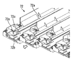
図33、図36等を参照して、押圧部材72cは、トナー補給装置(トナー容器収容部70)へのトナー容器32Yの水平方向の装着動作に連動してキャップ部34Yの側方に形成された押圧用レール34n2(図15等を参照できる。)に係合しながらキャップ部34Yを側方から付勢して滑動面(ボトル受面72a)におけるキャップ部34Yの短手方向(トナー容器32Yの装着方向に直交する方向であって、図47の左右方向である。)の姿勢を定めるためのものである。
As described above with reference to FIGS. 32 to 36 and the like, the bottle receiving portion 72 of the toner replenishing device (toner container housing portion 70) according to the first embodiment includes a stopper release urging portion 72b and a pressing member. 72c and the like are provided.
The stopper release urging portion 72b is interlocked with the horizontal mounting operation of the toner container 32Y to the toner replenishing device (toner container housing portion 70), and the stopper release portion 34d21 of the shutter member 34d (see FIGS. 18 and 21). It is a trapezoidal rib that protrudes upward with respect to the sliding surface (bottle receiving surface 72a) on which the toner container 32Y is mounted so as to abut against it and apply an external force from below.
Referring to FIGS. 33, 36, etc., the pressing member 72c is formed on the side of the cap portion 34Y in conjunction with the horizontal mounting operation of the toner container 32Y to the toner replenishing device (toner container housing portion 70). The cap portion 34Y is urged from the side while engaging with the pressing rail 34n2 (see FIG. 15 and the like), and the short side direction of the cap portion 34Y on the sliding surface (bottle receiving surface 72a) (toner container 32Y). Is the direction orthogonal to the mounting direction of FIG. 47 and is the left-right direction of FIG. 47).

そして、図47に示すように、トナー容器32Yの装着動作(又は、離脱動作)に連動してストッパ解除付勢部72bがストッパ解除部34d21(シャッタ部材34d)に当接しているときに、押圧部材72cが押圧用レール34n2に係合してキャップ部34Y(トナー容器32Y)の上方への移動を規制するように構成している。
詳しくは、図36等を参照して、ボトル受部72において、トナー容器32Yの着脱方向に対する押圧部材72cの位置と、トナー容器32Yの着脱方向に対するストッパ解除付勢部72bの位置と、が近くなるように構成されている。そして、トナー容器32Yの装着動作が進められて、押圧部材72c(突起部72c1)が押圧用レール34n2に係合してから、ストッパ解除付勢部72bとストッパ解除部34d21との当接が開始されるように、押圧部材72cの位置とストッパ解除付勢部72bの位置とがレイアウトされている。
47, when the stopper release urging portion 72b is in contact with the stopper release portion 34d21 (shutter member 34d) in conjunction with the mounting operation (or detachment operation) of the toner container 32Y, The member 72c is configured to be engaged with the pressing rail 34n2 to restrict the upward movement of the cap portion 34Y (toner container 32Y).
Specifically, referring to FIG. 36 and the like, in the bottle receiving portion 72, the position of the pressing member 72c with respect to the attaching / detaching direction of the toner container 32Y and the position of the stopper releasing biasing portion 72b with respect to the attaching / detaching direction of the toner container 32Y are close. It is comprised so that it may become. Then, after the mounting operation of the toner container 32Y is advanced and the pressing member 72c (projecting portion 72c1) is engaged with the pressing rail 34n2, the contact between the stopper release urging portion 72b and the stopper release portion 34d21 starts. As shown, the position of the pressing member 72c and the position of the stopper release urging portion 72b are laid out.

このような構成によって、シャッタ部材34dの開放動作にともないボトル受部72のストッパ解除付勢部72bによってストッパ解除部34n21(シャッタ部材34d)が上方への外力を受けてキャップ部34Y(トナー容器32Y)自体が上方へ持ち上げられそうになっても、押圧部材72cの底部と押圧用レール34n2の下面とが接触するため、キャップ部34Y(トナー容器32Y)の上方への移動が規制されることになる。これにより、トナー容器32Yの装着動作に連動して、シャッタ部材34dによってトナー排出口Wが確実に開閉されることになる。すなわち、シャッタ部材34dの開放動作にともないボトル受部72のストッパ解除付勢部72bによってストッパ解除部34n21が上方への外力を受けてキャップ部34Yがシャッタ部材34d(ストッパ解除部34n21)とともに完全に上方へ持ち上がってしまった場合、シャッタ変形部34d2が上方に弾性変形されずにストッパ部34d22と当接部34n5との当接状態が解除されず、シャッタ部材34dの開放動作がおこなわれないことになる(シャッタ部材34dが閉鎖されたままとなり、トナー排出口Wが開放されないことになる)。   With such a configuration, the stopper releasing portion 34n21 (shutter member 34d) receives an upward external force by the stopper releasing biasing portion 72b of the bottle receiving portion 72 as the shutter member 34d is opened, so that the cap portion 34Y (toner container 32Y) is received. ) Even if it is likely to be lifted upward, the bottom portion of the pressing member 72c and the lower surface of the pressing rail 34n2 are in contact with each other, so that the upward movement of the cap portion 34Y (toner container 32Y) is restricted. Become. Accordingly, the toner discharge port W is reliably opened and closed by the shutter member 34d in conjunction with the mounting operation of the toner container 32Y. That is, as the shutter member 34d is opened, the stopper release portion 34n21 receives an upward external force by the stopper release biasing portion 72b of the bottle receiving portion 72, so that the cap portion 34Y is completely moved together with the shutter member 34d (stopper release portion 34n21). If it is lifted upward, the shutter deforming portion 34d2 is not elastically deformed upward, the contact state between the stopper portion 34d22 and the contact portion 34n5 is not released, and the shutter member 34d is not opened. (The shutter member 34d remains closed, and the toner discharge port W is not opened).

ここで、図47、図48を参照して、本実施の形態1では、押圧部材72cが、押圧部材72cを短手方向(図47の右方向である。)に付勢する圧縮スプリング72eとともに、ホルダ72gに保持されている。
詳しくは、図48を参照して、押圧部材72cには、キャップ部34Yを短手方向に付勢する際の作用点となる突起部72c1、ホルダ72gの被係合部72g2に短手方向にスライド移動可能に係合する係合部72c2、等が設けられている。
ホルダ72gには、ボトル受部72の差込部72j(制限部)に係合する被差込部72g1、押圧部材72cを保持するための被係合部72g2、ボトル受部72のボス部72hにネジ締結するための長穴72g3、等が設けられている。
そして、ホルダ72gの壁面と押圧部材72cとの間に圧縮スプリング72eを設置した状態で、係合部72c2が被係合部72g2に係合した状態でホルダ72gに押圧部材72cを設置する。さらに、押圧部材72cと圧縮スプリング72eとが保持された状態のホルダ72gを、図48の一点鎖線で示す矢印方向に移動して、ボトル受部72の差込部72j(制限部)に被差込部72g1を差し込んだ状態で、不図示のネジを長穴72g3を介してボス部72hに螺合してボトル受部72に対するホルダ72g(押圧部材72c)の位置を固定する。
Here, with reference to FIGS. 47 and 48, in the first embodiment, the pressing member 72c together with the compression spring 72e that urges the pressing member 72c in the short direction (the right direction in FIG. 47). , Is held by a holder 72g.
Specifically, referring to FIG. 48, the pressing member 72c has a protrusion 72c1 serving as an action point when the cap portion 34Y is urged in the short direction, and the engaged portion 72g2 of the holder 72g in the short direction. An engaging portion 72c2 that is slidably engaged is provided.
The holder 72g includes an inserted portion 72g1 that engages with the insertion portion 72j (restricting portion) of the bottle receiving portion 72, an engaged portion 72g2 that holds the pressing member 72c, and a boss portion 72h of the bottle receiving portion 72. A long hole 72g3 and the like for screw fastening are provided.
Then, with the compression spring 72e installed between the wall surface of the holder 72g and the pressing member 72c, the pressing member 72c is installed on the holder 72g with the engaging portion 72c2 engaged with the engaged portion 72g2. Further, the holder 72g in a state where the pressing member 72c and the compression spring 72e are held is moved in the direction of the arrow indicated by the one-dot chain line in FIG. With the insertion portion 72g1 inserted, a screw (not shown) is screwed into the boss portion 72h through the elongated hole 72g3 to fix the position of the holder 72g (pressing member 72c) with respect to the bottle receiving portion 72.

このような構成において、ボトル受部72の差込部72jは、滑動面(ボトル受面72a)を有するボトル受部72にホルダ72gが設置された状態で、ホルダ72g(被差込部72g1)に係合してホルダ72gの上方への移動を制限する制限部として機能することになる。
すなわち、ボトル受部72に制限部としての差込部72jを設けることで、ボス部72hにおけるホルダ72gのネジ締結が緩んでしまった場合であっても、シャッタ部材34dの開放動作にともないボトル受部72のストッパ解除付勢部72bによってストッパ解除部34n21(シャッタ部材34d)が上方への外力を受けてキャップ部34Y(トナー容器32Y)自体が上方へ持ち上げられそうになって、押圧部材72cの底部と押圧用レール34n2の下面とが接触して押圧部材72cが上方へ持ち上げられそうになっても、差込部72j(制限部)と被差込部72g1(ホルダ72g)とが接触するため、キャップ部34Y(トナー容器32Y)の上方への移動が規制されることになる。これにより、トナー容器32Yの装着動作に連動して、シャッタ部材34dによってトナー排出口Wが確実に開閉されることになる。
In such a configuration, the insertion portion 72j of the bottle receiving portion 72 is a holder 72g (inserted portion 72g1) in a state where the holder 72g is installed in the bottle receiving portion 72 having a sliding surface (bottle receiving surface 72a). To function as a restricting portion that restricts the upward movement of the holder 72g.
That is, by providing the insertion portion 72j as the restriction portion in the bottle receiving portion 72, even when the screw fastening of the holder 72g in the boss portion 72h is loosened, the bottle receiving portion is released along with the opening operation of the shutter member 34d. The stopper release biasing portion 72b of the portion 72 causes the stopper release portion 34n21 (shutter member 34d) to receive an upward external force and the cap portion 34Y (toner container 32Y) itself is likely to be lifted upward, so that the pressing member 72c Even if the bottom portion and the lower surface of the pressing rail 34n2 come into contact with each other and the pressing member 72c is likely to be lifted upward, the insertion portion 72j (restriction portion) and the insertion portion 72g1 (holder 72g) contact each other. The upward movement of the cap portion 34Y (toner container 32Y) is restricted. Accordingly, the toner discharge port W is reliably opened and closed by the shutter member 34d in conjunction with the mounting operation of the toner container 32Y.

なお、本実施の形態1において、図49に示すように、トナー容器32Y(キャップ部34Y)の押圧用レール34n2において、押圧部材72cが当接する当接面を、底部に向かうほど押圧部材72cに近接するように傾斜して形成することもできる。このように、押圧用レール34n2の当接面を傾斜面とすることで、シャッタ部材34dの開放動作にともないボトル受部72のストッパ解除付勢部72bによってストッパ解除部34n21(シャッタ部材34d)が上方への外力を受けてキャップ部34Y(トナー容器32Y)自体が上方へ持ち上げられそうになっても、押圧部材72cの底部と押圧用レール34n2の傾斜面とが確実に接触してキャップ部34Yを下方へ付勢する反発力が作用するため、キャップ部34Y(トナー容器32Y)の上方への移動が規制されることになる。これにより、トナー容器32Yの装着動作に連動して、シャッタ部材34dによってトナー排出口Wが確実に開閉されることになる。   In the first embodiment, as shown in FIG. 49, in the pressing rail 34n2 of the toner container 32Y (cap portion 34Y), the contact surface with which the pressing member 72c comes into contact with the pressing member 72c toward the bottom. It can also be formed so as to be close to each other. Thus, by making the contact surface of the pressing rail 34n2 an inclined surface, the stopper releasing portion 34n21 (shutter member 34d) is moved by the stopper releasing biasing portion 72b of the bottle receiving portion 72 in accordance with the opening operation of the shutter member 34d. Even when the cap portion 34Y (toner container 32Y) itself is likely to be lifted upward due to an upward external force, the bottom portion of the pressing member 72c and the inclined surface of the pressing rail 34n2 are reliably in contact with each other and the cap portion 34Y. Since the repulsive force that urges the toner cartridge downward acts, the upward movement of the cap portion 34Y (toner container 32Y) is restricted. Accordingly, the toner discharge port W is reliably opened and closed by the shutter member 34d in conjunction with the mounting operation of the toner container 32Y.

また、本実施の形態1において、図50に示すように、押圧部材72cと押圧用レール34n2とを、シャッタ部材34dを挟むように短手方向(図50の左右方向である。)の両側に形成することもできる。すなわち、図47で説明した押圧部材72c(ホルダ72g)や押圧用レール34n2の機構を、短手方向の両側にそれぞれ設けることもできる。
このような構成により、シャッタ部材34dの開放動作にともないキャップ部34Y(トナー容器32Y)の上方への移動を規制する効果がさらに確実に発揮されることになる。
Further, in the first embodiment, as shown in FIG. 50, the pressing member 72c and the pressing rail 34n2 are arranged on both sides in the short direction (the left-right direction in FIG. 50) so as to sandwich the shutter member 34d. It can also be formed. That is, the mechanisms of the pressing member 72c (holder 72g) and the pressing rail 34n2 described in FIG. 47 can be provided on both sides in the short direction.
With such a configuration, the effect of restricting the upward movement of the cap portion 34Y (toner container 32Y) in accordance with the opening operation of the shutter member 34d is more reliably exhibited.

以上説明したように、本実施の形態1では、トナー容器32Yにおいて、シャッタ部材34dにシャッタ主部34d1との接続位置を基点にして弾性変形するシャッタ変形部34d2を設けて、そのシャッタ変形部34d2にシャッタ部材34dの開放方向の移動を規制するストッパ部34d22とそれを解除するストッパ解除部34d21とを設けている。そして、トナー補給装置(トナー容器収容部70)において、トナー容器32Yの装着動作に連動してストッパ解除付勢部72bがシャッタ部材34dのストッパ解除部34d21に当接しているときに、押圧部材72cがトナー容器32Yの押圧用レール34n2に係合してキャップ部34Yの上方への移動を規制するように構成している。これにより、トナー容器32Yが単体の状態でトナー排出口Wを開閉するシャッタ部材34dが簡単に移動することがなく、トナー容器32Yがトナー補給装置(トナー容器収容部70)に対して着脱される場合にはトナー容器32Yの着脱動作に連動してシャッタ部材34dがトナー排出口Yを確実に開閉することができる。   As described above, in the first embodiment, in the toner container 32Y, the shutter member 34d is provided with the shutter deformation portion 34d2 that is elastically deformed based on the connection position with the shutter main portion 34d1, and the shutter deformation portion 34d2 is provided. Are provided with a stopper part 34d22 for restricting movement of the shutter member 34d in the opening direction and a stopper releasing part 34d21 for releasing it. In the toner replenishing device (toner container housing portion 70), when the stopper release biasing portion 72b is in contact with the stopper release portion 34d21 of the shutter member 34d in conjunction with the mounting operation of the toner container 32Y, the pressing member 72c. Is configured to engage with the pressing rail 34n2 of the toner container 32Y to restrict the upward movement of the cap portion 34Y. Accordingly, the shutter member 34d for opening and closing the toner discharge port W is not easily moved in a state where the toner container 32Y is a single unit, and the toner container 32Y is attached to and detached from the toner replenishing device (toner container housing portion 70). In this case, the shutter member 34d can reliably open and close the toner discharge port Y in conjunction with the attaching / detaching operation of the toner container 32Y.

実施の形態2.
図51及び図52にて、この発明の実施の形態2について詳細に説明する。
図50は、実施の形態2におけるトナー補給装置において、トナー容器32Yの装着動作が進められるときに、押圧部材72cが押圧用レール34n2に係合する状態を示す模式図であって、前記実施の形態1における図47に対応する図である。また、図51は、図50のものとは別形態のトナー補給装置において、トナー容器32Yの装着動作が進められるときに、押圧部材72cが押圧用レール34n2に係合する状態を示す模式図であって、前記実施の形態1における図47に対応する図である。
本実施の形態2におけるトナー補給装置は、ボトル受部72の構成が、前記実施の形態1のものとは相違する。
Embodiment 2. FIG.
51 and 52, a second embodiment of the present invention will be described in detail.
FIG. 50 is a schematic diagram showing a state where the pressing member 72c is engaged with the pressing rail 34n2 when the mounting operation of the toner container 32Y is advanced in the toner replenishing device according to the second embodiment. It is a figure corresponding to FIG. 47 in the form 1. 51 is a schematic diagram showing a state in which the pressing member 72c is engaged with the pressing rail 34n2 when the mounting operation of the toner container 32Y is advanced in the toner replenishing device different from that of FIG. FIG. 48 is a diagram corresponding to FIG. 47 in the first embodiment.
In the toner replenishing device according to the second embodiment, the configuration of the bottle receiving portion 72 is different from that of the first embodiment.

図51を参照して、本実施の形態2におけるトナー補給装置も、前記実施の形態1のものと同様に、ボトル受部72にストッパ解除付勢部72bや押圧部材72c等が設けられている。そして、トナー容器32Yの装着動作(又は、離脱動作)に連動してストッパ解除付勢部72bがストッパ解除部34d21(シャッタ部材34d)に当接しているときに、押圧部材72cが押圧用レール34n2に係合してキャップ部34Y(トナー容器32Y)の上方への移動を規制するように構成されている。   Referring to FIG. 51, the toner replenishing device according to the second embodiment is also provided with a stopper release urging portion 72b, a pressing member 72c, and the like in the bottle receiving portion 72, as in the first embodiment. . When the stopper release urging portion 72b is in contact with the stopper release portion 34d21 (shutter member 34d) in conjunction with the mounting operation (or removal operation) of the toner container 32Y, the pressing member 72c is pressed against the pressing rail 34n2. And the upward movement of the cap part 34Y (toner container 32Y) is restricted.

ここで、図51を参照して、本実施の形態2では、トナー補給装置(ボトル受部72)へのトナー容器32Yの装着動作に連動してストッパ解除付勢部72bがストッパ解除部34d21(シャッタ部材34d)に当接しているときに、ストッパ解除部72bの上方の位置でキャップ部34Yの天井面に係合してキャップ部34Yの上方への移動を規制する壁部72rが、ボトル受部72にさらに設けられている。
このような構成により、シャッタ部材34dの開放動作にともないキャップ部34Y(トナー容器32Y)の上方への移動を規制する効果がさらに確実に発揮されることになる。すなわち、シャッタ部材34dの開放動作にともないキャップ部34Y(トナー容器32Y)が上方へ持ち上げられそうになっても、押圧部材72cの底部と押圧用レール34n2の下面とが接触するとともに、壁部72rがキャップ部34Yの天井面に接触するため、キャップ部34Y(トナー容器32Y)の上方への移動が規制されることになる。
Referring to FIG. 51, in the second embodiment, the stopper release urging portion 72b is linked to the stopper release portion 34d21 (in conjunction with the mounting operation of the toner container 32Y to the toner supply device (bottle receiving portion 72)). A wall portion 72r that engages with the ceiling surface of the cap portion 34Y at a position above the stopper release portion 72b and restricts the upward movement of the cap portion 34Y when it is in contact with the shutter member 34d) is provided with the bottle receiving portion. The unit 72 is further provided.
With such a configuration, the effect of restricting the upward movement of the cap portion 34Y (toner container 32Y) in accordance with the opening operation of the shutter member 34d is more reliably exhibited. That is, even when the cap portion 34Y (toner container 32Y) is likely to be lifted upward as the shutter member 34d opens, the bottom portion of the pressing member 72c and the lower surface of the pressing rail 34n2 come into contact with each other and the wall portion 72r. Is in contact with the ceiling surface of the cap portion 34Y, so that the upward movement of the cap portion 34Y (toner container 32Y) is restricted.

なお、本実施の形態2において、トナー補給装置(ボトル受部72)へのトナー容器32Yの装着動作に連動してストッパ解除付勢部72bがストッパ解除部34d21(シャッタ部材34d)に当接しているときに、ストッパ解除部72bの上方の位置でキャップ部34Yの天井面を押動してキャップ部34Yを下方へ付勢する第2押圧部材72pを、ボトル受部72にさらに設けることもできる。詳しくは、ボトル受部72の天井部に、スプリング72q(圧縮スプリング)によって下方に付勢された状態の第2押圧部材72pを設置することができる。
このような構成によっても、シャッタ部材34dの開放動作にともないキャップ部34Y(トナー容器32Y)の上方への移動を規制する効果がさらに確実に発揮されることになる。すなわち、シャッタ部材34dの開放動作にともないキャップ部34Y(トナー容器32Y)が上方へ持ち上げられそうになっても、押圧部材72cの底部と押圧用レール34n2の下面とが接触するとともに、第2押圧部材72pがキャップ部34Yを下方に向けて押動するため、キャップ部34Y(トナー容器32Y)の上方への移動が規制されることになる。
In the second embodiment, the stopper release biasing portion 72b contacts the stopper release portion 34d21 (shutter member 34d) in conjunction with the mounting operation of the toner container 32Y to the toner supply device (bottle receiving portion 72). A second pressing member 72p that urges the cap portion 34Y downward by pushing the ceiling surface of the cap portion 34Y at a position above the stopper release portion 72b can be further provided in the bottle receiving portion 72. . In detail, the 2nd press member 72p of the state urged | biased below by the spring 72q (compression spring) can be installed in the ceiling part of the bottle receiving part 72. FIG.
Even with such a configuration, the effect of restricting the upward movement of the cap portion 34Y (toner container 32Y) in accordance with the opening operation of the shutter member 34d is more reliably exhibited. That is, even when the cap portion 34Y (toner container 32Y) is likely to be lifted upward as the shutter member 34d is opened, the bottom of the pressing member 72c and the lower surface of the pressing rail 34n2 come into contact with each other and the second pressing Since the member 72p pushes the cap part 34Y downward, the upward movement of the cap part 34Y (toner container 32Y) is restricted.

以上説明したように、本実施の形態2においても、前記実施の形態1と同様に、トナー容器32Yにおいて、シャッタ部材34dにシャッタ主部34d1との接続位置を基点にして弾性変形するシャッタ変形部34d2を設けて、そのシャッタ変形部34d2にシャッタ部材34dの開放方向の移動を規制するストッパ部34d22とそれを解除するストッパ解除部34d21とを設けている。そして、トナー補給装置(トナー容器収容部70)において、トナー容器32Yの装着動作に連動してストッパ解除付勢部72bがシャッタ部材34dのストッパ解除部34d21に当接しているときに、押圧部材72cがトナー容器32Yの押圧用レール34n2に係合してキャップ部34Yの上方への移動を規制するように構成している。これにより、トナー容器32Yが単体の状態でトナー排出口Wを開閉するシャッタ部材34dが簡単に移動することがなく、トナー容器32Yがトナー補給装置(トナー容器収容部70)に対して着脱される場合にはトナー容器32Yの着脱動作に連動してシャッタ部材34dがトナー排出口Yを確実に開閉することができる。   As described above, also in the second embodiment, in the same manner as in the first embodiment, in the toner container 32Y, the shutter deformation portion that elastically deforms from the connection position of the shutter member 34d to the shutter main portion 34d1 in the shutter member 34d. 34d2 is provided, and the shutter deforming portion 34d2 is provided with a stopper portion 34d22 for restricting the movement of the shutter member 34d in the opening direction and a stopper releasing portion 34d21 for releasing the stopper portion 34d21. In the toner replenishing device (toner container housing portion 70), when the stopper release biasing portion 72b is in contact with the stopper release portion 34d21 of the shutter member 34d in conjunction with the mounting operation of the toner container 32Y, the pressing member 72c. Is configured to engage with the pressing rail 34n2 of the toner container 32Y to restrict the upward movement of the cap portion 34Y. Accordingly, the shutter member 34d for opening and closing the toner discharge port W is not easily moved in a state where the toner container 32Y is a single unit, and the toner container 32Y is attached to and detached from the toner replenishing device (toner container housing portion 70). In this case, the shutter member 34d can reliably open and close the toner discharge port Y in conjunction with the attaching / detaching operation of the toner container 32Y.

なお、前記各実施の形態では、トナー容器32Y、32M、32C、32K内にトナーのみを収容したが、トナーとキャリアとからなる2成分現像剤を現像装置に適宜に供給する画像形成装置に対してはトナー容器32Y、32M、32C、32K内に2成分現像剤を収容することもできる。その場合であっても、上述した前記各実施の形態と同様の効果を得ることができる。   In each of the above embodiments, only the toner is accommodated in the toner containers 32Y, 32M, 32C, and 32K. In other words, the two-component developer can be accommodated in the toner containers 32Y, 32M, 32C, and 32K. Even in that case, the same effects as those of the above-described embodiments can be obtained.

また、前記各実施の形態において、作像部6Y、6M、6C、6Kの一部又は全部をプロセスカートリッジとすることもできる。その場合であっても、上述した前記各実施の形態と同様の効果を得ることができる。   In each of the above embodiments, a part or all of the image forming units 6Y, 6M, 6C, and 6K may be a process cartridge. Even in that case, the same effects as those of the above-described embodiments can be obtained.

また、前記各実施の形態では、容器本体33Yを回転自在に構成することで、容器本体33Yの内部に収容したトナーが開口部Aに向けて搬送されるように構成した。これに対して、容器本体33Yがキャップ部34Yとともに非回転でトナー容器収容部70に保持されるように構成するとともに、容器本体33Y内に開口部Aに向けてトナーを搬送する搬送部材(例えば、軸部状に搬送コイルや複数の搬送羽根が設置されて、容器本体から独立したギアによって所定方向に回転する搬送部材である。)を設置することで、容器本体33Yの内部に収容したトナーが開口部Aに向けて搬送されるように構成してもよい。
そして、このようなトナー容器32Yに対しても、上述した前記各実施の形態と同様に本発明を適用することで、上述した前記各実施の形態と同様の効果を得ることができる。
In each of the above embodiments, the container main body 33Y is configured to be rotatable so that the toner contained in the container main body 33Y is conveyed toward the opening A. On the other hand, the container main body 33Y is configured to be held in the toner container storage unit 70 in a non-rotating manner together with the cap part 34Y, and a conveying member (for example, a toner conveying member) toward the opening A in the container main body 33Y (for example, , A conveying member that is provided with a conveying coil and a plurality of conveying blades in the shape of a shaft, and that rotates in a predetermined direction by a gear independent of the container main body. May be conveyed toward the opening A.
Further, by applying the present invention to such a toner container 32Y as in the above-described embodiments, the same effects as in the above-described embodiments can be obtained.

また、前記各実施の形態において、トナー補給装置60Y、60M、60C、60Kは、図1を参照して、いずれも、トナータンク部(61Y)、トナー搬送部(62Y、63Y)、トナー落下搬送経路(64Y)で形成されるトナー搬送経路が逆N字状(ロシア文字のИ字状)に形成されている(図1の紙面奥側からみた場合にはN字状となる。)。そして、各色のトナー搬送部(62Y、63Y)は、対応する色のプロセスカートリッジ(作像部6Y)の上方であって、装置本体100に対するプロセスカートリッジの着脱口の上方に設けられている。また、各色のトナー容器(32Y)、トナータンク部(61Y)、トナー搬送部(62Y)の搬送方向上流側は、対応する色のプロセスカートリッジではなく、隣接するプロセスカートリッジ(図1の左隣である。)の上方に設けられている。このような構成により、複数のプロセスカートリッジ(作像部)が並列に配設されたタンデム式の画像形成装置において、プロセスカートリッジ(作像部)の着脱操作をおこなう際にプロセスカートリッジとトナー補給装置とが干渉することなく、各色のトナー容器からプロセスカートリッジまでの縦方向のレイアウトをコンパクト化することができるとともに、トナー補給量のばらつきを生じさせない画像形成装置を提供することができる。   In each of the above embodiments, the toner replenishing devices 60Y, 60M, 60C, and 60K are all configured with reference to FIG. 1, the toner tank unit (61Y), the toner transport unit (62Y, 63Y), and the toner drop transport. The toner conveyance path formed by the path (64Y) is formed in an inverted N-shape (Russian И-shape) (when viewed from the back side of the sheet of FIG. 1, it is an N-shape). The toner transport sections (62Y, 63Y) for the respective colors are provided above the process cartridges (image forming section 6Y) for the corresponding colors and above the attachment / detachment opening of the process cartridge with respect to the apparatus main body 100. Further, the upstream side in the transport direction of each color toner container (32Y), toner tank unit (61Y), and toner transport unit (62Y) is not a process cartridge of the corresponding color but an adjacent process cartridge (on the left side in FIG. 1). It is provided above. With such a configuration, in the tandem image forming apparatus in which a plurality of process cartridges (image forming units) are arranged in parallel, the process cartridge and the toner replenishing device are used when the process cartridge (image forming unit) is attached and detached. In addition, the vertical layout from the toner container of each color to the process cartridge can be made compact, and an image forming apparatus that does not cause variations in the amount of toner replenishment can be provided.

なお、本発明が前記各実施の形態に限定されず、本発明の技術思想の範囲内において、前記各実施の形態の中で示唆した以外にも、前記各実施の形態は適宜変更され得ることは明らかである。また、前記構成部材の数、位置、形状等は前記各実施の形態に限定されず、本発明を実施する上で好適な数、位置、形状等にすることができる。   It should be noted that the present invention is not limited to the above-described embodiments, and within the scope of the technical idea of the present invention, the embodiments can be modified as appropriate in addition to those suggested in the embodiments. Is clear. In addition, the number, position, shape, and the like of the constituent members are not limited to the above embodiments, and can be set to a number, position, shape, and the like that are suitable for carrying out the present invention.

5Y 現像装置、
32Y、32M、32C、32K トナー容器、
33Y 容器本体、
34Y キャップ部、
34d シャッタ部材、
34d21 ストッパ解除部、
34n2 押圧用レール、
60Y、60M、60C、60K トナー補給装置、
70 トナー容器収容部、
72 ボトル受部、
72b ストッパ解除付勢部、
72c 押圧部材、
72c1 突起部、 72c2 係合部、
72e 圧縮スプリング、
72g ホルダ、
72g1 被差込部、 72g2 被係合部、 72g3 長穴、
72h ボス部、
72j 差込部(制限部)、
72p 第2押圧部材、
72q スプリング、
72r 壁部、
73 キャップ受部、
100 画像形成装置本体(装置本体)、 W トナー排出口。
5Y developing device,
32Y, 32M, 32C, 32K toner containers,
33Y container body,
34Y cap part,
34d shutter member,
34d21 stopper release part,
34n2 rail for pressing,
60Y, 60M, 60C, 60K toner supply device,
70 toner container housing,
72 bottle receiver,
72b Stopper release biasing part,
72c pressing member,
72c1 protrusion, 72c2 engagement part,
72e compression spring,
72g holder,
72g1 inserted part, 72g2 engaged part, 72g3 oblong hole,
72h Boss part,
72j plug-in part (limitation part),
72p second pressing member,
72q spring,
72r wall,
73 cap receiving part,
100 Image forming apparatus main body (apparatus main body), W toner discharge port.

特開平4−1681号公報JP-A-4-1681 特開2002−268344公報JP 2002-268344 A

Claims (7)

トナー容器が水平方向に移動されて着脱可能に設置されるトナー補給装置であって、
前記トナー容器は、トナーを容器外であって鉛直方向下方に排出するためのトナー排出口を底部に具備し、前記トナー排出口を開閉するシャッタ部材備え、
前記シャッタ部材は、その移動を規制するストッパ部を具備し、下方から外力を受けることにより前記ストッパ部による当該シャッタ部材の移動の規制が解除されるように構成され、
前記トナー容器の前記水平方向の装着動作に連動して前記シャッタ部材当接して下方から外力を与えるように、前記トナー容器が装着される滑動面に対して上方に突起するストッパ解除付勢部と、
前記トナー容器の前記水平方向の装着動作に連動して前記トナー容器の側方に形成された押圧用レールに係合しながら前記トナー容器を側方から付勢して前記滑動面における前記トナー容器の装着方向に直交する短手方向の姿勢を定める押圧部材と、
を備え、
前記トナー容器の装着動作に連動して前記ストッパ解除付勢部が前記シャッタ部材に当接しているときに、前記押圧部材が前記押圧用レールに係合して前記トナー容器の上方への移動を規制することを特徴とするトナー補給装置。
A toner replenishing device in which a toner container is moved horizontally and is detachably installed;
The toner container comprises a toner outlet for discharging a container outside the toner in the vertical direction downward to the bottom, a shutter member for opening and closing the toner discharge port,
The shutter member includes a stopper portion that restricts the movement of the shutter member, and is configured to release the restriction of the movement of the shutter member by the stopper portion by receiving an external force from below.
Wherein said toner container in conjunction with the horizontal direction of the mounting operation to provide an external force from the lower abuts against the shutter member, the stopper release biasing portion which protrudes upwardly with respect to sliding surface on which the toner container is attached When,
The toner container in the slideway by urging from the horizontal side of the toner container while in association with the mounting operation engages the pressing rail is formed on the side of the toner container of the toner container A pressing member that defines a posture in a short direction perpendicular to the mounting direction of
With
When the stopper release urging portion is in contact with the shutter member in conjunction with the mounting operation of the toner container, the pressing member engages with the pressing rail to move the toner container upward. A toner replenishing device characterized by regulating.
前記押圧部材と、前記押圧部材を前記短手方向に付勢する圧縮スプリングと、を保持するホルダと、
前記滑動面を有するボトル受部に前記ホルダが設置された状態で、前記ホルダに係合して前記ホルダの上方への移動を制限する制限部と、
をさらに備えたことを特徴とする請求項1に記載のトナー補給装置。
A holder that holds the pressing member and a compression spring that biases the pressing member in the short-side direction;
In a state where the holder is installed in the bottle receiving portion having the sliding surface, a limiting portion that engages with the holder and restricts the upward movement of the holder;
The toner replenishing device according to claim 1, further comprising:
前記トナー容器の前記押圧用レールは、前記押圧部材が当接する当接面が、底部に向かうほど前記押圧部材に近接するように傾斜して形成されたことを特徴とする請求項1又は請求項2に記載のトナー補給装置。   2. The pressing rail of the toner container is formed so that a contact surface with which the pressing member contacts is inclined so as to approach the pressing member toward the bottom. The toner replenishing device according to 2. 前記押圧部材と前記押圧用レールとは、前記シャッタ部材を挟むように前記短手方向の両側に形成されたことを特徴とする請求項1〜請求項3のいずれかに記載のトナー補給装置。   4. The toner replenishing device according to claim 1, wherein the pressing member and the pressing rail are formed on both sides in the lateral direction so as to sandwich the shutter member. 5. 前記トナー容器の装着動作に連動して前記ストッパ解除付勢部が前記シャッタ部材に当接しているときに、前記シャッタ部材の上方の位置で前記トナー容器の天井面に係合して前記トナー容器の上方への移動を規制する壁部をさらに備えたことを特徴とする請求項1〜請求項4のいずれかに記載のトナー補給装置。 When the stopper release biasing unit in synchronization with the attachment operation of the toner container is in contact with the shutter member, said toner container engages the ceiling surface of the toner container above the position of the shutter member The toner replenishing device according to claim 1, further comprising a wall portion that restricts the upward movement of the toner. 前記トナー容器の装着動作に連動して前記ストッパ解除付勢部が前記シャッタ部材に当接しているときに、前記シャッタ部材の上方の位置で前記トナー容器の天井面を押動して前記トナー容器を下方へ付勢する第2押圧部材をさらに備えたことを特徴とする請求項1〜請求項5のいずれかに記載のトナー補給装置。 When the stopper release biasing unit in synchronization with the attachment operation of the toner container is in contact with the shutter member, the toner container by pushing the ceiling surface of the toner container above the position of the shutter member The toner replenishing device according to claim 1, further comprising a second pressing member that biases the toner downward. 請求項1〜請求項6のいずれかに記載のトナー補給装置を備えたことを特徴とする画像形成装置。   An image forming apparatus comprising the toner supply device according to claim 1.
JP2010178512A 2010-08-09 2010-08-09 Toner supply device and image forming apparatus Expired - Fee Related JP5569241B2 (en)

Priority Applications (4)

Application Number Priority Date Filing Date Title
JP2010178512A JP5569241B2 (en) 2010-08-09 2010-08-09 Toner supply device and image forming apparatus
US13/198,097 US8655234B2 (en) 2010-08-09 2011-08-04 Toner supply assembly and image forming apparatus incorporating same
CN201310464526.0A CN103558744B (en) 2010-08-09 2011-08-04 Toner-adding device and imaging device
CN2011102216577A CN102375370B (en) 2010-08-09 2011-08-04 Toner supply assembly and image forming apparatus incorporating same

Applications Claiming Priority (1)

Application Number Priority Date Filing Date Title
JP2010178512A JP5569241B2 (en) 2010-08-09 2010-08-09 Toner supply device and image forming apparatus

Publications (3)

Publication Number Publication Date
JP2012037752A JP2012037752A (en) 2012-02-23
JP2012037752A5 JP2012037752A5 (en) 2013-11-07
JP5569241B2 true JP5569241B2 (en) 2014-08-13

Family

ID=45556259

Family Applications (1)

Application Number Title Priority Date Filing Date
JP2010178512A Expired - Fee Related JP5569241B2 (en) 2010-08-09 2010-08-09 Toner supply device and image forming apparatus

Country Status (3)

Country Link
US (1) US8655234B2 (en)
JP (1) JP5569241B2 (en)
CN (2) CN103558744B (en)

Families Citing this family (26)

* Cited by examiner, † Cited by third party
Publication number Priority date Publication date Assignee Title
SG183519A1 (en) * 2010-03-01 2012-10-30 Ricoh Co Ltd Toner container and image forming apparatus
RU2533927C1 (en) 2010-12-03 2014-11-27 Рикох Компани, Лтд. Container for powder, powder supply device and device for image formation
JP5765624B2 (en) 2011-08-19 2015-08-19 株式会社リコー Developing device, image forming apparatus, and process cartridge
JP5950156B2 (en) 2011-09-09 2016-07-13 株式会社リコー Process cartridge and image forming apparatus
CA2856903C (en) 2011-11-25 2017-03-21 Ricoh Company, Limited Powder container and image forming apparatus
JP5358706B2 (en) * 2012-02-20 2013-12-04 京セラドキュメントソリューションズ株式会社 Developer transport mechanism, developing device including the same, and image forming apparatus
JP5632422B2 (en) * 2012-05-23 2014-11-26 京セラドキュメントソリューションズ株式会社 Toner container and image forming apparatus
CA3066121C (en) 2012-06-03 2021-09-14 Ricoh Company, Limited Powder container and image forming apparatus
JP6015252B2 (en) 2012-08-31 2016-10-26 株式会社リコー Developer container, developer supply device, developing device, and image forming apparatus
JP2014164037A (en) * 2013-02-22 2014-09-08 Ricoh Co Ltd Container handling method, powder container, and image forming apparatus
US9465317B2 (en) 2013-02-25 2016-10-11 Ricoh Company, Ltd. Nozzle insertion member, powder container, and image forming apparatus
JP6064681B2 (en) 2013-03-01 2017-01-25 株式会社リコー Developer replenishing device for replenishing developer from storage container, image forming apparatus on which it is mounted, and transport device for transporting powder or fluid from storage container
JP6137882B2 (en) * 2013-03-11 2017-05-31 キヤノン株式会社 Developer supply container
CA3114929C (en) 2013-03-15 2023-01-10 Ricoh Company, Limited Powder container and image forming apparatus
JP6180140B2 (en) * 2013-03-19 2017-08-16 キヤノン株式会社 Developer supply container
JP6070392B2 (en) * 2013-04-30 2017-02-01 株式会社リコー Toner storage container support structure and image forming apparatus
JP6149509B2 (en) 2013-05-21 2017-06-21 株式会社リコー Toner container and image forming apparatus
US9298134B2 (en) * 2013-12-03 2016-03-29 Samsung Electronics Co., Ltd. Toner supply apparatus and toner cartidge
JP6320082B2 (en) * 2014-02-28 2018-05-09 キヤノン株式会社 Image forming apparatus
JP6432826B2 (en) 2014-08-11 2018-12-05 株式会社リコー Powder supply device and image forming apparatus
JP6380324B2 (en) * 2015-10-02 2018-08-29 京セラドキュメントソリューションズ株式会社 Toner container and image forming apparatus
CN112596357B (en) * 2016-04-07 2024-02-09 京瓷办公信息系统株式会社 Toner container and image forming apparatus
JP6919831B2 (en) * 2017-05-18 2021-08-18 株式会社リコー Developer container and image forming device
JP7005250B2 (en) * 2017-09-21 2022-01-21 キヤノン株式会社 Developer replenishment container
JP2022158083A (en) 2021-04-01 2022-10-14 株式会社リコー Image forming apparatus
CN115179097B (en) * 2022-07-28 2024-03-29 浙江亚微精密机床有限公司 Processing equipment capable of effectively reducing vibration of processing guide rail

Family Cites Families (29)

* Cited by examiner, † Cited by third party
Publication number Priority date Publication date Assignee Title
JPH041681A (en) * 1990-04-18 1992-01-07 Matsushita Electric Ind Co Ltd Toner cartridge
JP3167219B2 (en) 1993-04-15 2001-05-21 株式会社リコー Rotary developing device
JP3209833B2 (en) * 1993-07-28 2001-09-17 株式会社リコー Toner supply device
JP3336808B2 (en) 1994-04-11 2002-10-21 株式会社リコー Rotary developing device
JPH08146765A (en) 1994-09-20 1996-06-07 Ricoh Co Ltd Developing device
JP3520893B2 (en) * 1996-11-14 2004-04-19 株式会社リコー Developer storage container
JP2001242712A (en) 2000-02-28 2001-09-07 Ricoh Co Ltd Image forming device
JP2002268344A (en) 2001-03-06 2002-09-18 Fuji Xerox Co Ltd Developer-supplying device
CN1318923C (en) 2002-09-20 2007-05-30 株式会社理光 Developer limiting part, developing apparatus, processing cartridge and image forming device
JP4205531B2 (en) 2003-08-25 2009-01-07 株式会社リコー Conveying apparatus and image forming apparatus
JP4275518B2 (en) * 2003-12-09 2009-06-10 シャープ株式会社 Developer supply apparatus and image forming apparatus having the same
JP4343074B2 (en) 2004-03-19 2009-10-14 株式会社リコー Container storage device, conveyance device provided with the container storage device, and image forming apparatus
EP1589384B1 (en) 2004-04-23 2020-01-08 Ricoh Company, Ltd. Developer container
US7720416B2 (en) * 2004-08-16 2010-05-18 Ricoh Company, Ltd. Method and toner bottle for image forming apparatus capable of effectively supplying toner to image forming apparatus
JP4423140B2 (en) * 2004-08-31 2010-03-03 株式会社リコー Toner container, toner supply device, and image forming apparatus
JP4396946B2 (en) * 2005-01-26 2010-01-13 株式会社リコー Toner supply device and image forming apparatus
US7483659B2 (en) * 2005-08-31 2009-01-27 Kabushiki Kaisha Toshiba Toner cartridge and image forming apparatus for mounting the same
JP2007310148A (en) * 2006-05-18 2007-11-29 Toshiba Corp Toner cartridge
JP4878499B2 (en) * 2006-05-18 2012-02-15 株式会社東芝 Toner cartridge
JP4215784B2 (en) * 2006-07-13 2009-01-28 シャープ株式会社 Toner container, toner supply device, and image forming apparatus
JP4974595B2 (en) 2006-07-13 2012-07-11 株式会社リコー Developing device, process cartridge, and image forming apparatus
JP2008033090A (en) 2006-07-31 2008-02-14 Ricoh Co Ltd Powder conveying device, developing device, process cartridge and image forming apparatus
JP5403393B2 (en) 2008-03-28 2014-01-29 株式会社リコー Developing device, and image forming apparatus and process cartridge having the same
JP5240550B2 (en) 2008-03-31 2013-07-17 株式会社リコー Developing device, and image forming apparatus and process cartridge having the same
JP5429587B2 (en) 2008-04-01 2014-02-26 株式会社リコー Developing device, and image forming apparatus and process cartridge having the same
JP5382499B2 (en) 2008-07-01 2014-01-08 株式会社リコー Powder conveying apparatus, image forming apparatus, and process cartridge
JP5476871B2 (en) 2008-11-04 2014-04-23 株式会社リコー Developing device, process cartridge, and image forming apparatus
US8918030B2 (en) * 2008-11-27 2014-12-23 Ricoh Company, Limited Powder supplying device and image forming apparatus
JP5483101B2 (en) 2009-09-04 2014-05-07 株式会社リコー Toner container and image forming apparatus

Also Published As

Publication number Publication date
US20120033998A1 (en) 2012-02-09
CN103558744B (en) 2016-04-06
CN103558744A (en) 2014-02-05
CN102375370B (en) 2013-11-06
CN102375370A (en) 2012-03-14
US8655234B2 (en) 2014-02-18
JP2012037752A (en) 2012-02-23

Similar Documents

Publication Publication Date Title
JP5569241B2 (en) Toner supply device and image forming apparatus
JP5483101B2 (en) Toner container and image forming apparatus
WO2011027604A1 (en) Toner container and image forming device
JP4958325B2 (en) Toner container and image forming apparatus
JP5772004B2 (en) Toner container and image forming apparatus
CA2791357C (en) Toner container and image forming apparatus
JP5344326B2 (en) Toner container and image forming apparatus
JP5748113B2 (en) Toner container and image forming apparatus
JP5769050B2 (en) Toner container and image forming apparatus
JP5935245B2 (en) Developer storage container and image forming apparatus
JP5741727B2 (en) Toner container and image forming apparatus
JP5660378B2 (en) Toner container and image forming apparatus
JP5561603B2 (en) Toner container and image forming apparatus
JP2012189920A (en) Toner container and image forming device
JP5664266B2 (en) Toner container and image forming apparatus
JP5879871B2 (en) Toner container and image forming apparatus
JP5692639B2 (en) Toner container and image forming apparatus
JP5659815B2 (en) Toner container and image forming apparatus
JP2012032741A (en) Toner supply device and image forming apparatus
JP2013250474A (en) Toner bottle and image forming apparatus
JP2012189821A (en) Developer storage container, powder supply device and image forming apparatus

Legal Events

Date Code Title Description
A621 Written request for application examination

Free format text: JAPANESE INTERMEDIATE CODE: A621

Effective date: 20130527

A521 Request for written amendment filed

Free format text: JAPANESE INTERMEDIATE CODE: A523

Effective date: 20130925

A977 Report on retrieval

Free format text: JAPANESE INTERMEDIATE CODE: A971007

Effective date: 20131211

A131 Notification of reasons for refusal

Free format text: JAPANESE INTERMEDIATE CODE: A131

Effective date: 20131224

TRDD Decision of grant or rejection written
A01 Written decision to grant a patent or to grant a registration (utility model)

Free format text: JAPANESE INTERMEDIATE CODE: A01

Effective date: 20140527

A61 First payment of annual fees (during grant procedure)

Free format text: JAPANESE INTERMEDIATE CODE: A61

Effective date: 20140609

R151 Written notification of patent or utility model registration

Ref document number: 5569241

Country of ref document: JP

Free format text: JAPANESE INTERMEDIATE CODE: R151

LAPS Cancellation because of no payment of annual fees