RU2604564C2 - Laser confocal sensor metrology system - Google Patents
Laser confocal sensor metrology system Download PDFInfo
- Publication number
- RU2604564C2 RU2604564C2 RU2013129857/28A RU2013129857A RU2604564C2 RU 2604564 C2 RU2604564 C2 RU 2604564C2 RU 2013129857/28 A RU2013129857/28 A RU 2013129857/28A RU 2013129857 A RU2013129857 A RU 2013129857A RU 2604564 C2 RU2604564 C2 RU 2604564C2
- Authority
- RU
- Russia
- Prior art keywords
- lens
- measuring
- forming optics
- data
- forming
- Prior art date
Links
Images
Classifications
-
- G—PHYSICS
- G01—MEASURING; TESTING
- G01M—TESTING STATIC OR DYNAMIC BALANCE OF MACHINES OR STRUCTURES; TESTING OF STRUCTURES OR APPARATUS, NOT OTHERWISE PROVIDED FOR
- G01M11/00—Testing of optical apparatus; Testing structures by optical methods not otherwise provided for
- G01M11/02—Testing optical properties
- G01M11/0207—Details of measuring devices
-
- G—PHYSICS
- G01—MEASURING; TESTING
- G01M—TESTING STATIC OR DYNAMIC BALANCE OF MACHINES OR STRUCTURES; TESTING OF STRUCTURES OR APPARATUS, NOT OTHERWISE PROVIDED FOR
- G01M11/00—Testing of optical apparatus; Testing structures by optical methods not otherwise provided for
- G01M11/02—Testing optical properties
-
- G—PHYSICS
- G01—MEASURING; TESTING
- G01B—MEASURING LENGTH, THICKNESS OR SIMILAR LINEAR DIMENSIONS; MEASURING ANGLES; MEASURING AREAS; MEASURING IRREGULARITIES OF SURFACES OR CONTOURS
- G01B11/00—Measuring arrangements characterised by the use of optical techniques
- G01B11/02—Measuring arrangements characterised by the use of optical techniques for measuring length, width or thickness
- G01B11/06—Measuring arrangements characterised by the use of optical techniques for measuring length, width or thickness for measuring thickness ; e.g. of sheet material
-
- G—PHYSICS
- G01—MEASURING; TESTING
- G01B—MEASURING LENGTH, THICKNESS OR SIMILAR LINEAR DIMENSIONS; MEASURING ANGLES; MEASURING AREAS; MEASURING IRREGULARITIES OF SURFACES OR CONTOURS
- G01B11/00—Measuring arrangements characterised by the use of optical techniques
- G01B11/24—Measuring arrangements characterised by the use of optical techniques for measuring contours or curvatures
-
- G—PHYSICS
- G01—MEASURING; TESTING
- G01M—TESTING STATIC OR DYNAMIC BALANCE OF MACHINES OR STRUCTURES; TESTING OF STRUCTURES OR APPARATUS, NOT OTHERWISE PROVIDED FOR
- G01M11/00—Testing of optical apparatus; Testing structures by optical methods not otherwise provided for
- G01M11/02—Testing optical properties
- G01M11/0207—Details of measuring devices
- G01M11/0214—Details of devices holding the object to be tested
-
- G—PHYSICS
- G01—MEASURING; TESTING
- G01M—TESTING STATIC OR DYNAMIC BALANCE OF MACHINES OR STRUCTURES; TESTING OF STRUCTURES OR APPARATUS, NOT OTHERWISE PROVIDED FOR
- G01M11/00—Testing of optical apparatus; Testing structures by optical methods not otherwise provided for
- G01M11/02—Testing optical properties
- G01M11/0242—Testing optical properties by measuring geometrical properties or aberrations
- G01M11/025—Testing optical properties by measuring geometrical properties or aberrations by determining the shape of the object to be tested
Abstract
Description
СМЕЖНЫЕ ЗАЯВКИRELATED APPLICATIONS
Эта заявка притязает на приоритет Заявки на патент США серийный №13/305,666, которая была подана 28 ноября 2011 г.; а также Заявки на предпатент США серийный №61/418,148, которая была подана 30 ноября 2010 г., на содержание которых данная заявка опирается и ссылки на которые содержит.This application claims priority to US Patent Application Serial No. 13/305,666, which was filed November 28, 2011; as well as US Patent Application Serial No. 61 / 418,148, which was filed November 30, 2010, the contents of which this application is based on and contains links to.
ОБЛАСТЬ ПРИМЕНЕНИЯ ИЗОБРЕТЕНИЯFIELD OF THE INVENTION
Данное изобретение описывает аппарат для бесконтактного способа получения точных трехмерных измерений сухой контактной линзы, а конкретнее, использующий измерение сухой линзы для определения точной толщины контактной линзы.The present invention describes an apparatus for a non-contact method for obtaining accurate three-dimensional measurements of a dry contact lens, and more specifically, using a dry lens measurement to determine the exact thickness of a contact lens.
ПРЕДПОСЫЛКИ СОЗДАНИЯ ИЗОБРЕТЕНИЯBACKGROUND OF THE INVENTION
Офтальмологические линзы часто изготавливают методом литья, в котором мономерный материал помещается в полость, образованную оптическими поверхностями противоположных частей формы для литья. Многоразъемные формы для литья, используемые для придания гидрогелям формы полезного изделия, например, офтальмологической линзы, могут содержать, к примеру, первую часть формы для литья с выпуклой частью, которая совпадает с задней изогнутой поверхностью офтальмологической линзы, и вторую часть формы для литья с вогнутой частью, которая совпадает с передней изогнутой поверхностью офтальмологической линзы. Для изготовления линзы с применением таких форм для литья композиционное соединение неполимеризованных гидрогелевых линз помещается между одноразовой пластиковой частью формы для литья, образующей переднюю кривизну, и одноразовой пластиковой частью формы для литья, образующей заднюю кривизну.Ophthalmic lenses are often made by casting, in which the monomer material is placed in a cavity formed by the optical surfaces of the opposite parts of the casting mold. Multiple molds used to give hydrogels the shape of a useful product, for example, an ophthalmic lens, may contain, for example, a first part of the mold with a convex part that coincides with the back curved surface of the ophthalmic lens and a second part of the mold with concave the part that coincides with the front curved surface of the ophthalmic lens. For the manufacture of lenses using such injection molds, a composite compound of unpolymerized hydrogel lenses is placed between the disposable plastic portion of the injection mold forming the front curvature and the disposable plastic portion of the injection mold forming the front curvature.
Часть формы для литья, образующая переднюю кривизну, и часть формы для литья, образующая заднюю кривизну, обычно изготавливаются методом литья под давлением, в котором расплавленный пластик под давлением направляется в стальную оснастку точной механической обработки, по меньшей мере одна из поверхностей которой соответствует оптической степени качества.Part of the casting mold, forming the front curvature, and part of the casting mold, forming the back curvature, are usually made by injection molding, in which molten plastic is injected under pressure into precision machining steel tools, at least one of the surfaces of which corresponds to the optical degree quality.
Часть формы для литья, образующая переднюю кривизну, и часть формы для литья, образующая заднюю кривизну, совмещаются для того, чтобы обеспечить требуемые параметры формы линзы. Далее, композиционный состав подвергался полимеризации, например, воздействием тепла и света, таким образом, образовывая линзу. После полимеризации части формы для литья разделяются, и линза извлекается из частей формы.The mold part forming the front curvature and the mold part forming the rear curvature are combined in order to provide the required lens shape parameters. Further, the composition was polymerized, for example, by exposure to heat and light, thereby forming a lens. After polymerization, the parts of the mold are separated and the lens is removed from the parts of the mold.
Метод литья офтальмологических линз был особенно успешным для потоков больших объемов ограниченного количества размеров и мощностей линзы. Тем не менее характер оборудования и процессов метода литья под давлением затрудняет изготовление специфических линз на заказ, подходящих для глаза определенного пациента или для особого применения. Следовательно, изучали новые методы изготовления, такие как: токарная обработка заготовки линзы и метод стерео-литографии. Несмотря на то, что токарная обработка требует применения высоко-модульных материалов, этот метод является затратным по времени и ограниченным по разновидности доступных поверхностей, а методом стерео-литографии не удалось получить линзу, пригодную для использования людьми.The ophthalmic lens casting method has been particularly successful for large volume flows of a limited number of lens sizes and powers. Nevertheless, the nature of the equipment and processes of the injection molding method makes it difficult to manufacture specific lenses to order, suitable for the eyes of a particular patient or for special applications. Consequently, new manufacturing methods were studied, such as: turning the lens blank and the stereo lithography method. Despite the fact that turning requires the use of highly modular materials, this method is time-consuming and limited in terms of the variety of available surfaces, and the method of stereo lithography failed to obtain a lens suitable for human use.
В предыдущих описаниях приведены методы и аппараты изготовления индивидуальных линз с применением метода растровой литографии. Важным аспектом этих методов является то, что линза изготавливается инновационным способом, при котором одна из двух поверхностей линзы образуется произвольно, без использования метода литья, токарной или иной обработки. Произвольно образованная поверхность и основание могут содержать произвольно текущую текучую среду, заключенную в произвольно образованную поверхность. В результате, такую комбинацию иногда называют Предшественником линзы. Обработку фиксирующим облучением и гидратированием можно обычно использовать для преобразования Предшественника линзы в офтальмологическую линзу.In the previous descriptions, methods and devices for manufacturing individual lenses using the method of scanning lithography are given. An important aspect of these methods is that the lens is manufactured in an innovative way in which one of the two surfaces of the lens is formed arbitrarily, without the use of casting, turning or other processing. An arbitrarily formed surface and base may comprise an arbitrarily flowing fluid enclosed in an arbitrarily formed surface. As a result, such a combination is sometimes called the Lens Precursor. Fixative irradiation and hydration treatments can typically be used to convert the Lens Precursor into an ophthalmic lens.
Произвольно образованная линза таким способом может нуждаться в измерении для установления физических параметров линзы. Таким образом, для измерения линз, изготовленных из прототипов, необходимы способы и аппараты.An arbitrarily formed lens in this way may need to be measured to establish the physical parameters of the lens. Thus, to measure lenses made from prototypes, methods and apparatuses are needed.
ИЗЛОЖЕНИЕ СУЩНОСТИ ИЗОБРЕТЕНИЯSUMMARY OF THE INVENTION
Следовательно, настоящее изобретение направлено на способы и аппарат для измерения офтальмологической линзы, а в ряде вариантов исполнения изобретения, бесконтактный оптический инструмент может использоваться для определения точной толщины офтальмологической линзы. Некоторые варианты исполнения изобретения дополнительно содержат измерительный аппарат и способы измерения офтальмологической линзы в трех измерениях.Therefore, the present invention is directed to methods and apparatus for measuring an ophthalmic lens, and in some embodiments of the invention, a non-contact optical instrument can be used to determine the exact thickness of the ophthalmic lens. Some embodiments of the invention further comprise a measuring apparatus and methods for measuring an ophthalmic lens in three dimensions.
Как правило, настоящее изобретение содержит конфокальный датчик перемещения и оптический узел, который в ряде вариантов исполнения изобретения может содержать формирующую оптику, используемую в качестве задней искривленной поверхности для образования офтальмологической линзы. В некоторых предпочтительных воплощениях изобретения оптический узел может крепиться на подвижной оправе, которая может быть зафиксирована на вращающемся звене воздушной опоры.Typically, the present invention comprises a confocal displacement transducer and an optical assembly, which in some embodiments of the invention may comprise shaping optics used as a rear curved surface to form an ophthalmic lens. In some preferred embodiments of the invention, the optical assembly may be mounted on a movable frame that can be fixed to a rotating link of an air support.
Некоторые варианты воплощения изобретения могут также содержать аппарат для регулирования расположения одной или обеих формирующих оптических оправок, удерживающих офтальмологическую линзу и измерительное устройство. Например, в некоторых вариантах осуществления изобретения регулирование аппарата может проводиться до установления центра вращения формирующего оптического узла вдоль одной оси с датчиком перемещения, когда с помощью настроенного аппарата можно получить точные измерения линзы и формирующего оптического узла.Some embodiments of the invention may also include an apparatus for adjusting the location of one or both of the forming optical mandrels holding the ophthalmic lens and a measuring device. For example, in some embodiments of the invention, the adjustment of the apparatus can be carried out before establishing the center of rotation of the forming optical unit along the same axis as the displacement sensor, when using the tuned apparatus it is possible to obtain accurate measurements of the lens and the forming optical unit.
Другим аспектом в некоторых вариантах осуществления изобретения является то, что датчик перемещения может выполнять измерения формирующей оптической оправки, не содержащей линзу. Следовательно, файл данных измерения формирующей оптики можно использовать в качестве справочного файла, который можно применять для сравнения с измерением формирующей оптики, содержащей линзу. В некоторых вариантах осуществления изобретения полученные данные измерения могут сохраняться в различных видах.Another aspect in some embodiments of the invention is that the displacement sensor can measure a forming optical mandrel that does not contain a lens. Therefore, the measurement data file of the forming optics can be used as a reference file, which can be used to compare with the measurement of the forming optics containing the lens. In some embodiments, the acquired measurement data may be stored in various forms.
Другим аспектом в некоторых вариантах осуществления изобретения является то, что формирующий оптический узел может крепиться к подвижной оправе, а также может использоваться более одного раза для изготовления оптической линзы. Следовательно, можно провести измерение формирующего оптического узла, содержащего прикрепленную к нему линзу, а полученные данные измерений в дальнейшем могут быть сохранены в различных вариантах. Можно сравнить данные, описывающие одну или более формирующую оптику, офтальмологическую линзу и формирующую оптику, содержащую офтальмологическую линзу.Another aspect in some embodiments of the invention is that the forming optical unit can be attached to a movable frame, and can also be used more than once for the manufacture of an optical lens. Therefore, it is possible to measure the forming optical unit containing a lens attached to it, and the obtained measurement data can be stored in various ways in the future. You can compare data describing one or more forming optics, an ophthalmic lens and forming optics containing an ophthalmic lens.
Другие аспекты могут содержать файлы данных, содержащие информацию об измерениях, которая в дальнейшем может быть преобразована из величин сферических радиальных координат в величины одной или обеих осевых координат или иные пространственные величины. Различные файлы данных можно сопоставлять математическим способом для создания осевого файла толщины для измерения линзы.Other aspects may include data files containing measurement information, which can then be converted from values of spherical radial coordinates to values of one or both axial coordinates or other spatial values. Different data files can be matched mathematically to create an axial thickness file for measuring the lens.
Согласно одному аспекту изобретения предусмотрено устройство для измерения осевой толщины офтальмологической линзы, при этом устройство содержит:According to one aspect of the invention, there is provided a device for measuring the axial thickness of an ophthalmic lens, the device comprising:
крепежное устройство, выполненное с возможностью крепления оправки формирующей оптики;a mounting device configured to mount the mandrel of the forming optics;
измерительное устройство, содержащее датчик перемещения способный выполнять измерения перемещения в ответ на цифровой сигнал;a measuring device comprising a displacement sensor capable of performing displacement measurements in response to a digital signal;
процессор вычислительной машины, поддерживающий цифровую связь с измерительным устройством;a computer processor supporting digital communication with the measuring device;
устройство хранения данных цифровой среды, связанное с процессором вычислительной машины и хранящее программный код, который выполняется по требованию и служит на ряду с процессором и измерительным устройством для:a digital medium data storage device associated with a computer processor and storing program code that is executed on demand and serves along with the processor and measuring device for:
запоминания цифровых данных, описывающих перечень метрологических данных, при этом упомянутые метрологические данные содержат измерения;storing digital data describing the list of metrological data, while the mentioned metrological data contain measurements;
получения входных цифровых данных, описывающих одно или несколько измерений измерительного устройства, содержащих справочное измерение M1 оправки формирующей оптики без офтальмологической линзы на поверхности формирующей оптики и измерение М2 офтальмологической линзы, сформированной на той же формирующей оптике; иobtaining digital input data describing one or more measurements of the measuring device, containing a reference measurement M1 of the mandrel of the forming optics without an ophthalmic lens on the surface of the forming optics and measuring M2 of an ophthalmic lens formed on the same forming optics; and
вычисления величины осевой толщины офтальмологической линзы посредством вычитания метрологических данных, полученных при измерении M1 из метрологических данных, полученных при измерении М2.calculating the axial thickness of the ophthalmic lens by subtracting the metrological data obtained by measuring M1 from the metrological data obtained by measuring M2.
Кроме того, устройство может дополнительно содержать устройство обмена данными, соединяющее процессор вычислительной машины к распределенной сети, при этом исполняемый программный код дополнительно служит для передачи метрологических данных, описывающих измерения измерительного устройства, при этом упомянутые измерения, определяются набором точек данных и набор точек данных включает сферические радиальные координаты.In addition, the device may further comprise a data exchange device connecting the processor of the computing machine to the distributed network, wherein the executable program code further serves to transmit metrological data describing the measurements of the measuring device, wherein said measurements are determined by the set of data points and the set of data points includes spherical radial coordinates.
А также сферические радиальные координаты могут быть переведены в координаты осей Декартовой системы координат.As well as spherical radial coordinates can be translated into the coordinates of the axes of the Cartesian coordinate system.
КРАТКОЕ ОПИСАНИЕ ЧЕРТЕЖЕЙBRIEF DESCRIPTION OF THE DRAWINGS
На Фиг. 1 показана горизонтальная проекция офтальмологической линзы на оправке и конфокальный датчик перемещения в соответствии с некоторыми воплощениями настоящего изобретения.In FIG. 1 shows a horizontal projection of an ophthalmic lens on a mandrel and a confocal displacement transducer in accordance with some embodiments of the present invention.
На Фиг. 2А показано сечение подвижной оправы и формирующего оптического узла.In FIG. 2A shows a cross section of a movable frame and a forming optical assembly.
На Фиг. 2В показана горизонтальная проекция подвижной оправы и формирующей оптической оправки.In FIG. 2B shows a horizontal projection of a movable frame and a forming optical mandrel.
На Фиг. 3А показана боковая проекция измерительного аппарата, который содержит ось вращения датчика и множественные регуляторы датчика перемещения.In FIG. 3A shows a side view of a measuring apparatus that comprises a rotation axis of a sensor and multiple displacement sensor controls.
На Фиг. 3В показан крупный план боковой проекции измерительного аппарата, который содержит ось вращения формирующей оптики и множественные регуляторы формирующей оптики.In FIG. 3B shows a close-up of the side projection of the measuring apparatus, which contains the rotation axis of the forming optics and multiple regulators of the forming optics.
На Фиг. 4 показаны шаги процедуры способа в соответствии с некоторыми дополнительными аспектами настоящего изобретения.In FIG. 4 shows the steps of a method procedure in accordance with some additional aspects of the present invention.
На Фиг. 5А и 5В показаны данные измерений, представленные в сферических радиальных координатах.In FIG. 5A and 5B show measurement data presented in spherical radial coordinates.
На Фиг. 6 показан процессор, который может использоваться для внедрения некоторых вариантов осуществления настоящего изобретения.In FIG. 6 shows a processor that can be used to implement some embodiments of the present invention.
ПОДРОБНОЕ ОПИСАНИЕ ИЗОБРЕТЕНИЯDETAILED DESCRIPTION OF THE INVENTION
Настоящее изобретение предоставляет аппарат и способы измерения толщины одной или обеих линз и Предшественника линзы. В следующих разделах будет приведено подробное описание вариантов осуществления настоящего изобретения. Здесь представлено описание и предпочтительного, и альтернативного вариантов осуществления изобретения, хотя наиболее подробно описаны примеры осуществления изобретения, и понятно, что специалистам в данной области техники варианты, модификации и изменения изобретения будут очевидны. Таким образом, необходимо понимать, что указанные примеры возможных вариантов осуществления не ограничивают широту аспектов описываемого изобретения. Этапы процедуры способа, описанные в данном патенте, перечислены в логической последовательности в данном обсуждении. Но эта последовательность никоим образом не ограничивает порядок, в котором можно выполнять эти шаги, если порядок не утвержден специально. Кроме того, не все перечисленные этапы необходимы для успешной реализации настоящего изобретения, и дополнительные этапы могут вводиться в различных реализациях настоящего изобретения.The present invention provides apparatus and methods for measuring the thickness of one or both of the lenses and the Lens Precursor. The following sections will describe in detail the embodiments of the present invention. Descriptions of both preferred and alternative embodiments of the invention are provided herein, although embodiments of the invention are described in more detail, and it will be understood that those skilled in the art will recognize, modify and modify the invention. Thus, it should be understood that these examples of possible embodiments do not limit the breadth of aspects of the described invention. The process steps described in this patent are listed in logical sequence in this discussion. But this sequence in no way limits the order in which these steps can be performed, unless the order is specifically approved. In addition, not all of these steps are necessary for the successful implementation of the present invention, and additional steps may be introduced in various implementations of the present invention.
ОПРЕДЕЛЕНИЯDEFINITIONS
В данном описании и формуле изобретения настоящего изобретения могут использоваться различные термины, к которым будут применяться следующие определения:In this description and the claims of the present invention, various terms may be used to which the following definitions will apply:
Используемый в настоящей заявке термин "актиничное излучение" означает излучение, которое способно инициировать химическую реакцию, такую как, например, полимеризация Реакционной смеси.As used herein, the term “actinic radiation” means radiation that is capable of initiating a chemical reaction, such as, for example, polymerization of a Reaction mixture.
Используемый в настоящей заявке термин «изогнутый» означает линию или изгиб, подобный согнутому луку.As used herein, the term “curved” means a line or curvature similar to a bent bow.
Используемый в настоящей заявке термин "Закон Бера", который иногда называют "Закон Бугера-Ламберта-Бера", состоит в следующем: I(х)/10=ехр(-сх), где I(х) - интенсивность, как функция расстояния х от облученной поверхности, I0 интенсивность падающего на поверхность пучка, показатель поглощения поглощающего компонента, с - концентрация поглощающего компонента.Used in this application, the term "Beer's Law", sometimes referred to as the "Bouguer-Lambert-Bera Law", is as follows: I (x) / 10 = exp (-x), where I (x) is the intensity as a function of distance x from the irradiated surface, I0 is the intensity of the beam incident on the surface, the absorption coefficient of the absorbing component, s is the concentration of the absorbing component.
Используемый в настоящей заявке термин "коллимировать" означает ограничивать угол конуса излучения, такого как световое излучение, которое исходит как выходящее из аппарата, получающего излучение как входящее; в ряде вариантов осуществления угол конуса может ограничиваться таким образом, что исходящие световые лучи параллельны. Таким образом, «коллиматор» представляет собой устройство, выполняющее эту функцию, а «коллимированный» описывает его воздействие на излучение.As used herein, the term “collimate” means to limit the angle of a cone of radiation, such as light radiation, that comes out from an apparatus receiving radiation as incoming; in some embodiments, the cone angle can be limited so that the outgoing light rays are parallel. Thus, a “collimator” is a device that performs this function, while a “collimator” describes its effect on radiation.
Используемый в настоящей заявке термин «ЦМУ» (цифровое микрозеркальное устройство) относится к бистабильному пространственному модулятору света, состоящему из массива подвижных микрозеркал, функционально сопряженных с и установленных на чип КМОП-памяти. Каждое зеркало управляется независимо путем загрузки данных в ячейку памяти непосредственно под данным зеркалом для направления отраженного света, позволяя отображать пиксел видеоданных на пиксел экрана. Загружаемые данные электростатически управляют углом наклона зеркала, которое может находиться в двух состояниях: под углом +Х градусов (вкл.) и под углом -X градусов (выкл.). Для данных устройств X может принимать значение 10 или 12 градусов (номинальные значения). Отраженный находящимися во «включенном» состоянии зеркалами свет проходит через проектирующую линзу и направляется на экран. Находящиеся в «выключенном» состоянии зеркала отражают свет так, чтобы создать темное поле, тем самым задавая фоновый уровень черного для изображения. Сами изображения создаются модуляцией уровня серого путем быстрого переключения зеркал между двумя состояниями с частотой, достаточной для усредненного восприятия наблюдателем. Описанное ЦМУ иногда представляет собой цифровую проекционную систему DLP (Digital Light Processing).Used in this application, the term "CMU" (digital micromirror device) refers to a bistable spatial light modulator, consisting of an array of movable micromirrors functionally coupled with and installed on a CMOS memory chip. Each mirror is independently controlled by loading data into a memory location directly below this mirror to direct reflected light, allowing you to display a pixel of video data on a pixel on the screen. The downloaded data electrostatically controls the angle of the mirror, which can be in two states: at an angle of + X degrees (on) and at an angle of -X degrees (off). For these devices, X can take a value of 10 or 12 degrees (nominal values). The light reflected in the “on” state of the mirrors passes through the projection lens and is directed onto the screen. Mirrors that are in the “off” state reflect light so as to create a dark field, thereby setting the background black level for the image. The images themselves are created by modulating the gray level by quickly switching mirrors between two states with a frequency sufficient for the average perception by the observer. The described DSP is sometimes a digital projection system DLP (Digital Light Processing).
Используемый в настоящей заявке термин «ЦМУ-скрипт» относится к протоколу управления пространственным модулятором света, а также к управляющим сигналам для любого компонента системы, например, источника света или барабана с фильтрами, каждый из которых может состоять из упорядоченной по времени последовательности команд. Использование сокращения ЦМУ не предполагает ограничение использования данного термина для обозначения конкретного типа или размера пространственного модулятора света.Used in this application, the term "CMU-script" refers to the control protocol of the spatial light modulator, as well as to control signals for any component of the system, for example, a light source or a drum with filters, each of which may consist of a time-ordered sequence of commands. The use of the abbreviation CMU does not imply a restriction on the use of this term to indicate a specific type or size of a spatial light modulator.
Используемый в настоящей заявке термин «фиксирующее излучение» означает актиничное излучение, подходящее для одного или более процесса из: полимеризация и поперечное сшивание, по сути, всей Реакционной смеси, содержащей Предшественник линзы или линзу.As used herein, the term “fixative radiation” means actinic radiation suitable for one or more of: polymerization and crosslinking of essentially the entire Reaction mixture containing the lens Precursor or lens.
Используемый в настоящей заявке термин «текучая линзообразующая реакционная среда» означает текучую Реакционную смесь в нативной форме, прореагировавшей форме или в частично прореагировавшей форме; часть или вся Реакционная среда в ходе дальнейшей обработки может сформировать часть офтальмологической линзы.As used herein, the term “fluid lens-forming reaction medium” means a fluid Reaction mixture in native form, in a reacted form, or in a partially reacted form; part or all of the reaction medium during further processing may form part of the ophthalmic lens.
Используемые в настоящей заявке термины «произвольный» или «произвольно образованный» описывают поверхность, образованную сшиванием реакционной смеси, а не сформированную методом литья, токарной обработки или лазерной абляции.Used in this application, the terms "arbitrary" or "randomly formed" describe a surface formed by stitching the reaction mixture, and not formed by casting, turning or laser ablation.
Используемый в настоящей заявке термин «точка гелеобразования» означает точку, при которой впервые наблюдается появление геля или нерастворимой фракции. Точка гелеобразования представляет собой степень преобразования, при которой жидкая полимеризуемая смесь переходит в твердое состояние.As used herein, the term “gel point” means a point at which a gel or insoluble fraction is first observed. The gel point is the degree of conversion at which the liquid polymerizable mixture becomes solid.
Используемый в настоящей заявке термин «линза» означает любое офтальмологическое устройство, расположенное в глазу или на нем. Эти устройства могут обеспечивать оптическую коррекцию зрения, а могут использоваться в косметических целях. Например, термин «линза» может означать контактную линзу, искусственный хрусталик, накладную линзу, глазную вставку, оптическую вставку или иное подобное устройство, с помощью которого корректируется или изменяется зрение или косметически улучшается физиология глаза (например, цвет радужной оболочки), не затрудняя при этом зрительное восприятие. В некоторых осуществлениях предпочтительные линзы, составляющие предмет изобретения, представляют собой мягкие контактные линзы, изготовленные из силиконовых эластомеров или гидрогелей, в том числе, в частности, силиконгидрогелей и фторгидрогелей.Used in this application, the term "lens" means any ophthalmic device located in the eye or on it. These devices can provide optical vision correction, and can be used for cosmetic purposes. For example, the term “lens” can mean a contact lens, an artificial lens, a false lens, an eye insert, an optical insert, or another similar device by which vision is corrected or altered or the physiology of the eye is improved cosmetically (for example, the color of the iris) without complicating this is visual perception. In some embodiments, preferred lenses of the invention are soft contact lenses made of silicone elastomers or hydrogels, including, in particular, silicone hydrogels and fluorohydrogels.
Используемый в настоящей заявке термин «предшественник линзы» означает составной объект, состоящий из формы предшественника линзы и текучей линзообразующей реакционной смеси, находящейся в контакте с формой предшественника линзы. Например, в ряде вариантов осуществления текучая линзообразующая реакционная среда формируется в процессе изготовления формы предшественника линзы в объеме реакционной смеси. Отделяя форму предшественника линзы и сцепленную текучую линзообразующую реакционную среду от объема реакционной смеси, используемого для образования формы предшественника линзы, можно получить предшественник линзы. К тому же предшественник линзы можно преобразовать в другой объект либо извлечением значительного количества текучей линзообразующей реакционной смеси, либо преобразованием значительного количества текучей линзообразующей реакционной среды в нетекучий, объединенный материал.As used herein, the term “lens precursor” means a composite object consisting of a lens precursor form and a fluid lens-forming reaction mixture in contact with the lens precursor form. For example, in a number of embodiments, a fluid lens-forming reaction medium is formed during the manufacturing process of the lens precursor form in the volume of the reaction mixture. By separating the lens precursor form and the adherent fluid lens-forming reaction medium from the volume of the reaction mixture used to form the lens precursor form, a lens precursor can be obtained. In addition, the lens precursor can be converted to another object either by extracting a significant amount of the fluid lens-forming reaction mixture, or by converting a significant amount of the fluid lens-forming reaction medium into a non-fluid, combined material.
Используемый в настоящей заявке термин «форма предшественника линзы» означает нетекучий объект с по меньшей мере одной поверхностью оптического качества, которая подходит для совмещения с офтальмологической линзой в ходе дальнейшей обработки.As used herein, the term “lens precursor shape” means a non-fluid object with at least one surface of optical quality that is suitable for alignment with an ophthalmic lens during further processing.
Используемый в настоящей заявке термин «линзообразующая смесь» или «реакционная смесь» или «РСМ» (реакционная смесь мономера) означает мономер или полимер, который может быть сшит для изготовления офтальмологической линзы. Различные варианты осуществления могут содержать линзообразующие смеси с одной или более добавками, такими как: УФ-блокаторы, красители, фотоинициаторы или катализаторы и другие добавки, которые могут понадобиться в составе офтальмологических линз, таких как контактные или интраокулярные линзы.As used herein, the term “lens forming mixture” or “reaction mixture” or “PCM” (monomer reaction mixture) means a monomer or polymer that can be crosslinked to make an ophthalmic lens. Various embodiments may comprise lens-forming mixtures with one or more additives, such as: UV blockers, dyes, photoinitiators or catalysts, and other additives that may be needed as part of ophthalmic lenses, such as contact or intraocular lenses.
Используемый в настоящей заявке термин «форма для литья» означает жесткий или полужесткий объект, который может использоваться для изготовления линз из неполимеризованных составов. Некоторые предпочтительные формы для литья состоят из двух частей, образующих переднюю изогнутую часть формы для литья и заднюю изогнутую часть формы для литья.As used in this application, the term "mold" means a rigid or semi-rigid object that can be used to make lenses from unpolymerized formulations. Some preferred molds consist of two parts forming the front curved part of the mold and the back curved part of the mold.
Используемый в настоящей заявке термин «компонент поглощения излучения» означает компонент, поглощающий излучение, который может содержаться в составе реакционного мономерного смешанного состава и который может поглощать излучение в определенном диапазоне длин волн.As used herein, the term “radiation absorption component” means a radiation absorbing component that may be contained in a reaction monomer mixed composition and that can absorb radiation in a specific wavelength range.
Реакционная смесь (также в настоящей заявке называемая линзообразующей смесью или реакционной смесью мономера, также в значении «линзообразующая смесь»).The reaction mixture (also referred to in the present application as a lens-forming mixture or monomer reaction mixture, also in the sense of “lens-forming mixture”).
Используемый в настоящей заявке термин «выпрессовка из формы для литья» означает либо полное отделение линзы от формы для литья, либо ее свободное присоединение к форме настолько, что ее можно извлечь легким встряхиванием формы или вытолкнуть с помощью поршня.As used herein, the term “extruding from a casting mold” means either completely detaching the lens from the casting mold or freely adhering to the mold so that it can be removed by lightly shaking the mold or pushing it out with a piston.
Используемый в настоящей заявке термин «стереолитографический предшественник линзы» означает предшественник линзы, форма которого была образована с использованием стереолитографии.As used herein, the term “stereolithographic lens precursor” means a lens precursor whose shape has been formed using stereolithography.
Используемый в настоящей заявке термин «подложка» означает физический объект, на котором размещаются или формируются другие объекты; также в настоящей заявке для него используется термин оправка.Used in this application, the term "substrate" means a physical object on which other objects are placed or formed; also in this application, the term mandrel is used for it.
Используемый в настоящей заявке термин «промежуточная линзообразующая реакционная среда» означает реакционную смесь, которая остается на форме предшественника линзы и не полимеризуется полностью, и может оставаться в текучем или нетекучем состоянии. Значительная часть промежуточной линзообразующей реакционной среды удаляется в один или несколько следующих этапов, прежде чем включается в состав офтальмологической линзы: очистка, сольватирование и гидратация. Таким образом, для ясности сочетание формы предшественника линзы и промежуточной линзообразующей смеси не будет считаться предшественником линзы.As used herein, the term “intermediate lens-forming reaction medium” means a reaction mixture that remains on the lens precursor form and does not completely polymerize, and may remain in a flowing or non-flowing state. A significant part of the intermediate lens-forming reaction medium is removed in one or more of the following steps before being included in the composition of an ophthalmic lens: cleaning, solvation and hydration. Thus, for clarity, the combination of the shape of the lens precursor and the intermediate lens-forming mixture will not be considered the lens precursor.
Используемые в настоящей заявке термины «воксел» или «воксел актиничного излучения» являются объемным элементом, представляющим значение на обычной сетке трехмерного пространства. Несмотря на то, что воксел может выглядеть как трехмерный пиксел, в случаях когда пискел представляет данные двухмерного изображения, воксел содержит третью координату. Кроме того, хотя воксел часто используются для визуализации и анализа медицинских и научных данных, в настоящем изобретении воксел применяется для задания границ дозы актиничного излучения, попадающего в некоторый объем реакционной смеси и тем самым контролирующего скорость поперечной сшивки или полимеризации в конкретном элементе объема реакционной смеси. В качестве примера в рамках настоящего изобретения вокселы считаются расположенными в один слой, прилегающими к двухмерной поверхности формы для литья, при этом используемое актиничное излучение может быть направлено по нормали к данной двухмерной поверхности и вдоль общей для всех вокселов оси. В качестве примера обрабатываемый объем реакционной смеси может быть сшит или полимеризован в соответствии с разбиением на матрицу из 768×768 вокселов.Used in this application, the terms "voxel" or "voxel actinic radiation" are a volumetric element that represents a value on a regular grid of three-dimensional space. Despite the fact that a voxel may look like a three-dimensional pixel, in cases where a pixel represents two-dimensional image data, the voxel contains a third coordinate. In addition, although a voxel is often used to visualize and analyze medical and scientific data, in the present invention, a voxel is used to define dose limits for actinic radiation falling into a certain volume of the reaction mixture and thereby controlling the rate of crosslinking or polymerization in a particular element of the volume of the reaction mixture. As an example, in the framework of the present invention, voxels are considered to be in a single layer adjacent to the two-dimensional surface of the casting mold, while the actinic radiation used can be directed normal to this two-dimensional surface and along the axis common to all voxels. As an example, the treated volume of the reaction mixture can be crosslinked or polymerized in accordance with the partition into a matrix of 768 × 768 voxels.
Используемый в настоящей заявке термин «воксельный предшественник линзы» означает предшественник линзы, форма которого была создана с использованием литографии с разбиением рабочего пространства на вокселы (растровая литография).As used in this application, the term “voxel lens precursor” means a lens precursor whose shape was created using lithography with dividing the workspace into voxels (raster lithography).
Используемый в настоящей заявке термин «Xgel» означает степень химического превращения сшиваемой реакционной смеси, при которой доля геля в смеси становится больше нуля.Used in this application, the term "Xgel" means the degree of chemical conversion of a crosslinkable reaction mixture, in which the proportion of gel in the mixture becomes greater than zero.
Используемый в настоящей заявке термин «оправка» обозначает изделие с сформированной поверхностью для закрепления офтальмологической линзы.Used in this application, the term "mandrel" means a product with a formed surface for fixing an ophthalmic lens.
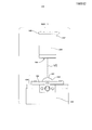
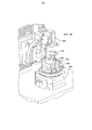
Теперь обратимся к Фиг. 1, на которой изображена горизонтальная проекция офтальмологической линзы 101 на формирующей оптической оправке 102 и конфокальный датчик перемещения 100, в соответствии с рядом вариантов осуществления настоящего изобретения. В ряде вариантов осуществления датчик перемещения 100 может содержать одну или более линз объектива 106, источник луча лазера 107 и камеру 108. В ряде дополнительных вариантов осуществления лазерный луч, проходя через центральный оптический участок линзы объектива, 109 может фокусироваться на поверхности-мишени. В ряде других вариантов осуществления линза объектива 106 может совершать колебания вверх и вниз, изменяя фокальную точку лазерного луча 109 до тех пор, пока камера 108 не определит положение, в котором линза объектива 106 получает точное фокусирование. К тому же, в ряде вариантов осуществления лазерный луч 109 может отражаться от поверхности на камеру 108, таким образом позволяя определить высоту мишени датчика перемещения 100.Turning now to FIG. 1, which shows a horizontal projection of an
Более того, в ряде вариантов осуществления датчик перемещения 100 может рассчитывать перемещение поверхности. В ряде предпочтительных вариантов осуществления датчик перемещения 100, к примеру, может иметь рабочий диапазон в 30 мм и может измерять толщину от плюс Y до минус 1 мм, поддерживая при этом адекватную точность перемещения. Для примера, в ряде вариантов осуществления в качестве датчика перемещения 100 может использоваться модель Keyence LT-9030M (Япония) или любой другой датчик перемещения, известный в данной отрасли.Moreover, in a number of embodiments, the
Как показано на Фиг. 1, формирующая оптическая оправка 102 может использоваться для создания формы задней изогнутой поверхности линзы 101. В ряде вариантов осуществления формирующая оптическая оправка 102 может быть посажена на металическую раму 103, которые вместе составляют формирующий оптический узел 104. В ряде других вариантов осуществления подвижное крепежное устройство 105 может использоваться для закрепления формирующего оптического узла 104 на своем месте. Для специалистов в данной отрасли техники, подвижную оправу 105 можно описать как механизм крепления объекта в фиксированном положении относительно другого объекта. В ряде вариантов осуществления используемые в одних и тех же целях подвижная оправка 105 и способ позволяют формирующему оптическому узлу 104 сохранять точное положение каждый раз, когда формирующий оптический узел 104 крепится на подвижную оправу 105. Более того, в ряде вариантов осуществления в зависимости от того, в каком положении датчик перемещения 100 снимает справочные измерения на формирующей оптике 102, сохранение узлом формирующей оптики 104 каждый раз точного положения закрепления может иметь функциональную важность для получения точных данных измерения. Таким образом, в ряде вариантов осуществления сохранение точного положения узла формирующей оптики 104 может, например, позволить каждый раз происходить одному или обоим процессам образования и измерения линзы 101 в конкретном месте формирующей оптики 102, а также позволяет каждый раз измерять формирующую оптику 102 в конкретном положении.As shown in FIG. 1, the forming
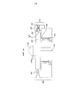
Теперь обратимся к Фиг. 2А и 2В. На Фиг. 2А изображено поперечное сечение подвижной оправы 205 и узла формирующей оптики 204, при чем узел формирующей оптики 204 содержит и оправку формирующей оптики 202 и металлическую раму 203. На Фиг. 2В показана горизонтальная проекция подвижной оправы 205 и оправка формирующей оптики 202. В ряде вариантов осуществления верхняя часть пластины подвижной оправы 205 может содержать один или несколько шариков 200, заключенных в просверленное отверстие. В ряде дополнительных вариантов осуществления подвижная оправа 205 может содержать один или несколько винтов 201, с помощью которых можно отрегулировать высоту шарика 200 так, чтобы шарик 200 касался узла формирующей оптики 204 в одной точке, при этом узел формирующей оптики 204 может располагаться на уровне оси вращения формирующей оптики.Turning now to FIG. 2A and 2B. In FIG. 2A shows a cross-section of a
Более того, в ряде других вариантов осуществления подвижная оправа 205 может содержать один или несколько регулировочных штифтов с полукруглой головкой 207 и поршень 206, который помогает в закреплении подвижной оправы 205 на своем месте. Таким образом, в ряде вариантов осуществления узел пружины и штифта 210 может содержать один или более из следующих элементов: поршень 206, который может заезжать в канавку, пружину 208, которая может располагаться за поршнем 206, и винт узла пружины и штифта 209, который может зажимать пружину 208.Moreover, in a number of other embodiments, the
В ряде аспектов данного изобретения поршень 206 может свободно перемещаться внутрь и наружу, при этом поршень 206 может устанавливать узел формирующей оптики 204 на место, проталкивая себя в желобок 211. Конкретнее, в ряде вариантов осуществления желобок 211 может, например, закреплять узел формирующей оптики 204 правильно повернутым, чтобы пружина 208 могла протолкнуть поршень 206 в желобок 211. В ряде дополнительных вариантов осуществления узел пружины и штифта 210 с помощью поршня 206 может толкать узел формирующей оптики 204 в определенном направлении (например, вправо или влево), чтобы край узла формирующей оптики 204 сталкивался с одним или обоими регулирующими штифтами с полукруглой головкой 207. Более того, в ряде вариантов осуществления регулирование регулирующего штифта с полукруглой головкой 207 позволяет полностью отрегулировать расположение узла формирующей оптики 204 по оси X и Y.In a number of aspects of the present invention, the
В другом аспекте может использоваться насос отрицательного атмосферного давления для подачи отрицательного атмосферного давления или давление вакуума 212 в полость между узлом формирующей оптики 204 и подвижной оправой 205 по оси вращения формирующей оптики. В ряде вариантов осуществления, вакуум может использоваться, например, для закрепления узла формирующей оптики 204 с возможностью последующего снятия внизу на одном или нескольких пружин 208, а проталкивание узла формирующей оптики 204 навстречу одному или нескольким регулировочным штифтам с полукруглой головкой поршнем 206 может быть запрещено.In another aspect, a negative atmospheric pressure pump may be used to supply negative atmospheric pressure or
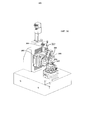
Теперь обратимся к Фиг. 3А и 3В; на Фиг. 3А показана боковая проекция измерительного аппарата, содержащего ось вращения датчика 301 и множественные регуляторы датчика перемещения 300. На Фиг. 3В показана увеличенная боковая проекция измерительного аппарата, содержащего ось вращения формирующей оптики 308 и множественные регуляторы формирующей оптики 302. В ряде вариантов осуществления, датчик 300 может, к примеру, вращаться с помощью оси вращения датчика 301, а узел формирующей оптики 304, прикрепленный к подвижному крепежному устройству 305, может вращаться с помощью оси вращения формирующей оптики 308 на протяжении всего времени измерения. Для примера заметим, что ось вращения формирующей оптики 308 и ось вращения датчика 301, обе являются инновационными моторизированными системами управления осями на воздушных подшипниках, которые позволяют ограничить радиальное биение и осевое смещение обеих осей. В ряде предпочтительных вариантов осуществления, датчик перемещения 300 и оправка формирующей оптики 302 могут располагаться вдоль одной оси, тогда датчик 300 во время измерений центрируется над центральной сферой оправки формирующей оптики 302.Turning now to FIG. 3A and 3B; in FIG. 3A is a side view of a measuring apparatus comprising a rotation axis of a
В ряде вариантов осуществления, датчик перемещения 300 может, например, выравниваться вдоль оси вручную путем регулирования одного из регуляторов 303 оси х датчика, регуляторов 306 оси у датчика, регуляторов 307 оси z датчика. Следовательно, в ряде вариантов осуществления, регулятор 303 оси х датчика помогает выровнять датчик перемещения 300 по оси х, позволяя перемещать датчик 300 вдоль оси х. В ряде дополнительных вариантов осуществления, регулятор 306 оси у датчика помогает выровнять датчик перемещения 300 по оси у, позволяя перемещать датчик 300 вдоль оси у. И далее, в ряде вариантов осуществления, регулятор 307 оси z датчика помогает выровнять датчик перемещения 300 по оси z, позволяя перемещать датчик 300 вдоль оси z. Дополнительно, в предпочтительных вариантах осуществления, регулятор 407 оси z датчика служит для перемещения датчика перемещения 300 на определенный рабочий радиус, предпочтительно на 30 мм выше оправки формирующей оптики 302.In a number of embodiments, the
В ряде других вариантов осуществления, узел формирующей оптики 304 путем регулировки подвижной оправы 305 может быть выставлен по оси вручную путем регулирования одного или обоих регуляторов 309 формирующей оптики по оси х и регулятора 310 формирующей оптики по оси у. В ряде вариантов осуществления, регулировка одного или обоих регуляторов 309 формирующей оптики по оси х и регулятора 310 формирующей оптики по оси у, например, могут исправить эксцентриситет узла формирующей оптики 304 при креплении на ось вращения формирующей оптики 308, в то время как формирующая оптика 302 может вращаться вокруг центра оси вращения формирующей оптики 308.In a number of other embodiments, the forming
Более того, в ряде дополнительных вариантов осуществления, при проведении измерений датчик перемещения 300 может быть повернут с помощью оси вращения датчика 301 на угол до приблизительно 65 градусов от положения, соответствующего тому, в которое помещается датчик 300 при размещении прямо над оправкой формирующей оптики 302. Соответственно, в ряде вариантов осуществления, начальный угол датчика перемещений 300 для снятия показаний может быть большим или меньшим по отношению к одному или обоим из размера диаметра поверхности и размера поверхностного участка. Например, в ряде вариантов осуществления, начальный угол датчика перемещения 300 может быть меньшим для измерения оптической зоны линзы в противовес измерению всей линзы, и в противоположность измерению формирующей оптики 302 без линзы.Moreover, in a number of additional embodiments, when taking measurements, the
Соответственно, ось вращения формирующей оптики 308 может начать непрерывно вращаться во время проведения измерения. В ряде вариантов осуществления, во время измерения линзы, например, вслед за одним полным поворотом оси вращения формирующей оптики 308, датчик перемещения 300 может сам себя обнулить на оставшемся участке формирующей оптики 302 вне кромки линзы. В некоторых последующих вариантах осуществления, датчик перемещения 300 может снимать измерения точки данных в сферических радиальных координатах с интервалом в 1/4 градуса поворота, производимого осью вращения формирующей оптики 308, таким образом собирая данные обо всех 1440 точках данных за один полный поворот оси вращения 308.Accordingly, the rotation axis of the forming
В ряде дополнительных вариантов осуществления, для каждого угла поворота θ° оси вращения формирующей оптики может существовать величина для θ и величина для каждого угла поворота ρ оси поворота датчика 301, при этом может быть определена величина перемещения. В ряде вариантов осуществления, например, значения Rho могут быть рассчитаны таким образом, что равномерно увеличивающиеся круги данных смогут быть собраны во время измерений, при этом один круг данных может потребовать один поворот узла формирующей оптики 304, за которым последует последующее вращение, поскольку ось вращения датчика 301 одновременно перемещается в следующее положение ρ. Более того, в ряде аспектов, ось вращения датчика 301 вместе с датчиком перемещения 300, могут передвигаться вверх к каждому положению ρ, при этом точки данных можно собрать для каждого осевого круга, например, для 140 осевых кругов во время измерения.In a number of additional embodiments, for each rotation angle θ ° of the axis of rotation of the forming optics, there can be a value for θ and a value for each angle of rotation ρ of the axis of rotation of the
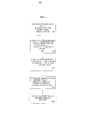
И наоборот, в ряде дополнительных аспектов настоящего изобретения, см. Фиг. 4, блок-схема показывает этапы выполнения способа, которые могут быть внедрены для получения метрологических данных и для определения осевой толщины не гидратированной офтальмологической линзы. В ряде вариантов осуществления, офтальмологическая линза может быть изготовлена, и ее потребуется измерить для определения, соответствует ли линза требуемым характеристикам. На этапе 400, в ряде вариантов осуществления настоящего изобретения, измерительный аппарат может быть соосно выставлен таким образом, что датчик перемещения будет прямо центрирован над центром сферы формирующей оптики. На этапе 401, можно провести справочное измерение оправки формирующей оптики без линзы на поверхности формирующей оптики (M1). На этапе 402, можно провести измерение линзы, изготовленной на той же формирующей оптике (М2), упомянутой выше для этапа 401, при этом может быть проведено измерение формирующей оптики. На этапе 403, метрологические данные, полученные измерениями M1 и М2, могут быть переведены из сферических радиальных координат в координаты Декартовой системы координат (см. Фиг. 5). На этапе 404, можно рассчитать величину осевой толщины линзы (М3), при этом величина М3 может быть равна разности файла метрологических данных М2 и файла метрологических данных M1.Conversely, in a number of further aspects of the present invention, see FIG. 4, the flowchart shows the steps of the method that can be implemented to obtain metrological data and to determine the axial thickness of the non-hydrated ophthalmic lens. In a number of embodiments, an ophthalmic lens can be manufactured and will need to be measured to determine if the lens meets the required characteristics. At
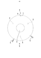
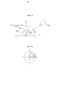
Теперь обратимся к Фиг. 5А и Фиг. 5В; на Фиг. 5А показан датчик перемещения 500, выполняющий измерение линзы 501 на оправке формирующей оптики 502, при этом метрологические данные представляются в сферических радиальных координатах. На Фиг. 5В показана горизонтальная проекция оправки формирующей оптики 502, при этом метрологические данные представляются в сферических радиальных координатах. В ряде образцов осуществления изобретения записанные сферические радиальные координаты могут быть переведены в осевую толщину в системе декартовых координат, таких как х и у, применяя одну или несколько схем математических вычислений. Далее представлено несколько образцов расчета, которые могут использоваться, где:Turning now to FIG. 5A and FIG. 5B; in FIG. 5A shows a
Ri=полярный радиусR i = polar radius
rs=радиус узла формирующей оптики, определенный в результате отдельного измеренияr s = radius of the forming optics node determined as a result of a separate measurement
key=значение показаний датчика Keyencekey = Keyence sensor value
Уравнение 1:Equation 1:
Sin(90-ρ)=Z/(rs+key)Sin (90-ρ) = Z / (r s + key)
Z=(rs+key) sin(90-ρ)Z = (r s + key) sin (90-ρ)
For θ, Zi=(rs+keyi) sin(90-ρi)For θ, Z i = (r s + key i ) sin (90-ρ i )
Уравнение 2:Equation 2:
Cos (90-ρi)=Ri/rs+keyi Cos (90-ρ i ) = R i / r s + key i
Ri=(rs+keyi) (cos(90-ρi))R i = (r s + key i ) (cos (90-ρ i ))
Уравнение 3:Equation 3:
cosθi=Xi/Ri cosθ i = X i / R i
Xi=(rs+keyi) (cos(90-ρi)) (cosθi)X i = (r s + key i ) (cos (90-ρ i )) (cosθ i )
Уравнение 4:Equation 4:
sinθi=Yi/Ri sinθ i = Y i / R i
Yi=(rs+keyi) (cos (90-ρi)) (sinθi)Y i = (r s + key i ) (cos (90-ρ i )) (sinθ i )
В радиальных координатах:In radial coordinates:
Три координаты: θ, ρ, и значение показаний датчика фирмы Keyence + сферический радиус Three coordinates: θ, ρ, and Keyence sensor reading value + spherical radius
В осевых координатах:In axial coordinates:
Три координаты: X, Y и Z, где Z может обозначать толщину.Three coordinates: X, Y and Z, where Z can indicate thickness.
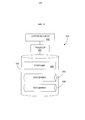
Теперь обратимся к Фиг. 6, на которой изображен контроллер 600, который может использоваться для внедрения ряда аспектов настоящего изобретения. Блок процессора 601, который может содержать один или несколько процессоров, соединен с устройством обмена данными 602, конфигурированным для обмена данными через сеть обмена данными. Устройство обмена данными 602 может использоваться для обмена данными, например, с одним или несколькими контроллерами аппарата или компонентами производственного оборудования.Turning now to FIG. 6, which depicts a
Процессор 601 может также использоваться в обмене данными с устройством хранения данных 603. Устройство хранения данных 603, содержащее комбинацию магнитных устройств хранения данных {например, магнитная лента или приводы жестких дисков), оптических устройств хранения данных и/или полупроводниковых запоминающих устройств, таких как Оперативное запоминающее устройство (ОЗУ) и Постоянное запоминающее устройство (ПЗУ).A processor 601 may also be used in communication with a
Устройство хранения данных 603 может хранить исполняющую программу 604 для управления процессором 601. Процессор 601 выполняет команды программы 604 и, таким образом, работает в соответствии с настоящим изобретением, например, выполняя указанные выше этапы. Например, процессор 601 может получать информацию о метрологических данных, включая справочные измерения формирующей оптики, измерения линзы и т.п. Устройство хранения данных 603 может также сохранять соответствующие данные в одной или нескольких базах данных 605 и 606.The
ВЫВОД:OUTPUT:
Так как изобретение описано со ссылкой на конкретные варианты осуществления, специалистам в данной области будет понятно, что существует возможность внесения различных изменений и эквивалентных замен его элементов, не выходящих за пределы объема изобретения. Кроме того, существует возможность реализации различных модификаций для адаптации конкретной ситуации или материала к методике изобретения, не выходя за пределы объема изобретения.Since the invention has been described with reference to specific embodiments, it will be understood by those skilled in the art that it is possible to make various changes and equivalent replacements to its elements without departing from the scope of the invention. In addition, it is possible to implement various modifications to adapt a specific situation or material to the methodology of the invention, without going beyond the scope of the invention.
Следовательно, предполагается, что изобретение не ограничено конкретными вариантами осуществления, рассматриваемыми как наилучший предполагаемый вариант осуществления изобретения, а, напротив, изобретение будет содержать в себе все варианты осуществления в пределах сущности и объема приложенных пунктов формулы изобретения.Therefore, it is assumed that the invention is not limited to specific embodiments considered as the best contemplated embodiment of the invention, but rather, the invention will include all embodiments within the spirit and scope of the attached claims.
Claims (5)
крепежное устройство, выполненное с возможностью крепления оправки формирующей оптики;
измерительное устройство, содержащее датчик перемещения, способный выполнять измерения перемещения в ответ на цифровой сигнал;
процессор вычислительной машины, поддерживающий цифровую связь с измерительным устройством;
устройство хранения данных цифровой среды, связанное с процессором вычислительной машины и хранящее программный код, который выполняется по требованию и служит на ряду с процессором и измерительным устройством для:
запоминания цифровых данных, описывающих перечень метрологических данных, при этом упомянутые метрологические данные содержат измерения;
получения входных цифровых данных, описывающих одно или несколько измерений измерительного устройства, содержащих справочное измерение M1 оправки формирующей оптики без офтальмологической линзы на поверхности формирующей оптики и измерение М2 офтальмологической линзы, сформированной на той же формирующей оптике; и
вычисления величины осевой толщины офтальмологической линзы посредством вычитания метрологических данных, полученных при измерении M1 из метрологических данных, полученных при измерении М2.1. A device for measuring the axial thickness of an ophthalmic lens, the device contains:
a mounting device configured to mount the mandrel of the forming optics;
a measuring device comprising a displacement sensor capable of performing displacement measurements in response to a digital signal;
a computer processor supporting digital communication with the measuring device;
a digital medium data storage device associated with a computer processor and storing program code that is executed on demand and serves along with the processor and measuring device for:
storing digital data describing the list of metrological data, while the mentioned metrological data contain measurements;
obtaining digital input data describing one or more measurements of the measuring device, containing a reference measurement M1 of the mandrel of the forming optics without an ophthalmic lens on the surface of the forming optics and measuring M2 of an ophthalmic lens formed on the same forming optics; and
calculating the axial thickness of the ophthalmic lens by subtracting the metrological data obtained by measuring M1 from the metrological data obtained by measuring M2.
Applications Claiming Priority (5)
| Application Number | Priority Date | Filing Date | Title |
|---|---|---|---|
| US41814810P | 2010-11-30 | 2010-11-30 | |
| US61/418,148 | 2010-11-30 | ||
| US13/305,666 US20120133958A1 (en) | 2010-11-30 | 2011-11-28 | Laser confocal sensor metrology system |
| US13/305,666 | 2011-11-28 | ||
| PCT/US2011/062408 WO2012075016A1 (en) | 2010-11-30 | 2011-11-29 | Laser confocal sensor metrology system |
Publications (2)
| Publication Number | Publication Date |
|---|---|
| RU2013129857A RU2013129857A (en) | 2015-01-10 |
| RU2604564C2 true RU2604564C2 (en) | 2016-12-10 |
Family
ID=46126447
Family Applications (2)
| Application Number | Title | Priority Date | Filing Date |
|---|---|---|---|
| RU2013129857/28A RU2604564C2 (en) | 2010-11-30 | 2011-11-29 | Laser confocal sensor metrology system |
| RU2013129822/28A RU2584070C2 (en) | 2010-11-30 | 2011-11-29 | Measurement system with laser confocal sensor |
Family Applications After (1)
| Application Number | Title | Priority Date | Filing Date |
|---|---|---|---|
| RU2013129822/28A RU2584070C2 (en) | 2010-11-30 | 2011-11-29 | Measurement system with laser confocal sensor |
Country Status (13)
| Country | Link |
|---|---|
| US (3) | US20120133958A1 (en) |
| EP (2) | EP2646788B1 (en) |
| JP (2) | JP5922144B2 (en) |
| KR (2) | KR101886615B1 (en) |
| CN (3) | CN103229037B (en) |
| AR (2) | AR084042A1 (en) |
| AU (2) | AU2011336781A1 (en) |
| BR (2) | BR112013013437A2 (en) |
| CA (2) | CA2819348C (en) |
| RU (2) | RU2604564C2 (en) |
| SG (2) | SG190881A1 (en) |
| TW (2) | TWI589850B (en) |
| WO (2) | WO2012075013A1 (en) |
Cited By (1)
| Publication number | Priority date | Publication date | Assignee | Title |
|---|---|---|---|---|
| RU2769373C1 (en) * | 2018-12-12 | 2022-03-30 | Сэн-Гобэн Гласс Франс | Method of measuring geometrical discrepancies between curved surfaces of a plurality of analyzed materials and a curved surface of a reference material |
Families Citing this family (31)
| Publication number | Priority date | Publication date | Assignee | Title |
|---|---|---|---|---|
| ES2788853T3 (en) | 2010-12-06 | 2020-10-23 | 3Shape As | System with 3D user interface integration |
| US20140268029A1 (en) * | 2013-03-15 | 2014-09-18 | Johnson & Johnson Vision Care, Inc. | Method and ophthalmic device for providing visual representations to a user |
| US9465236B2 (en) * | 2013-03-15 | 2016-10-11 | Johnson & Johnson Vision Care, Inc. | Ophthalmic devices incorporating photonic elements |
| IL231446A0 (en) * | 2013-03-15 | 2014-08-31 | Johnson & Johnson Vision Care | Methods and ophthalmic device for providing visual representations to a user |
| EP2992310B1 (en) * | 2013-05-02 | 2019-07-31 | Carl Zeiss Vision International GmbH | Method and system for determining the spatial structure of an object |
| DE102013219838B4 (en) * | 2013-09-30 | 2015-11-26 | Carl Zeiss Ag | Method and system for determining the spatial structure of an object |
| CN103610511B (en) * | 2013-12-05 | 2015-06-03 | 天津开发区合普工贸有限公司 | Laser cornea cutting device for experimental animal |
| CN103631098B (en) * | 2013-12-23 | 2016-08-17 | 成都虹博宇光电科技有限公司 | A kind of contactless photoetching machine leveling and focusing system, method and litho machine |
| US9645412B2 (en) | 2014-11-05 | 2017-05-09 | Johnson & Johnson Vision Care Inc. | Customized lens device and method |
| CN104613881A (en) * | 2015-02-12 | 2015-05-13 | 江苏宇迪光学股份有限公司 | Lens center thickness measuring device and method based on double face confocal measurement |
| EP3059575B1 (en) * | 2015-02-20 | 2020-11-25 | Alcon Inc. | Method for determining the quality of a surface of an ophthalmic lens |
| US9863842B2 (en) | 2015-09-24 | 2018-01-09 | Novartis Ag | Method for characterizing an ophthalmic lens |
| CN106556348A (en) * | 2015-09-24 | 2017-04-05 | 上海思信科学仪器有限公司 | Sapphire thickness measurement equipment |
| CN106556349A (en) * | 2015-09-24 | 2017-04-05 | 上海思信科学仪器有限公司 | Water film thickness measuring instrument |
| US10607335B2 (en) * | 2016-06-28 | 2020-03-31 | Johnson & Johnson Vision Care, Inc. | Systems and methods of using absorptive imaging metrology to measure the thickness of ophthalmic lenses |
| US10830666B2 (en) * | 2016-10-31 | 2020-11-10 | Alcon Inc. | Contact lens inspection method and system |
| CN106483049B (en) * | 2016-11-01 | 2019-08-13 | 浙江省计量科学研究院 | A kind of non-contact self-checking device and method of the Hegman grind gage error of indication |
| TWI652469B (en) | 2017-09-15 | 2019-03-01 | 財團法人國家實驗硏究院 | Test device and method for testing contact lens and test device for testing hydrous element |
| CN108562228B (en) * | 2018-06-08 | 2024-03-26 | 昆山迈致治具科技有限公司 | Automatic change continuous test equipment |
| CN109579713A (en) * | 2018-08-17 | 2019-04-05 | 深圳中科飞测科技有限公司 | Measuring device and measurement method |
| CN109000571B (en) * | 2018-09-11 | 2021-05-14 | 中国科学院光电技术研究所 | Thickness consistency detection device |
| CN109342024B (en) * | 2018-09-16 | 2020-10-27 | 林玲 | Contact lens screening equipment and screening method thereof |
| CN109365312B (en) * | 2018-09-16 | 2020-10-13 | 嘉兴麦瑞网络科技有限公司 | Big data management screening assembly line of contact lens |
| US11635344B2 (en) * | 2019-02-01 | 2023-04-25 | Optikos Corporation | Portable optic metrology thermal chamber module and method therefor |
| CN110425988A (en) * | 2019-08-16 | 2019-11-08 | 宾努克斯科技(佛山)有限公司 | A kind of relative laser calibrator |
| KR102296485B1 (en) * | 2020-02-21 | 2021-08-31 | 임완철 | Automatic stage alignment structure for optical inspection device |
| JP2022003332A (en) * | 2020-06-16 | 2022-01-11 | イメージ エーアイ プライベート リミテッドEmage AI Pte Ltd | System and method for detecting refractive power of dry ophthalmic lenses |
| CN111895924B (en) * | 2020-07-15 | 2022-03-11 | 广州精点科技有限公司 | Automatic lens thickness measuring device |
| US11835418B2 (en) | 2021-09-30 | 2023-12-05 | Opto-Alignment Technology, Inc. | Simultaneous multi-surface non-contact optical profiler |
| CN114440790B (en) * | 2022-01-27 | 2022-11-01 | 浙江大学 | Method and device for simultaneously detecting surface shape and thickness distribution of inner wall and outer wall of thin-wall revolving body |
| US11761756B2 (en) | 2022-01-27 | 2023-09-19 | Zhejiang University | Method and device for simultaneously detecting surface shapes and thickness distribution of inner and outer walls of thin-wall rotating body |
Citations (3)
| Publication number | Priority date | Publication date | Assignee | Title |
|---|---|---|---|---|
| US5675406A (en) * | 1995-10-17 | 1997-10-07 | Hughes Electronics | Portable device for ensuring that a center thickness of a lens is within a predetermined tolerance |
| US7053997B2 (en) * | 2001-01-23 | 2006-05-30 | Menicon Co., Ltd. | Method of obtaining particulars of ophthalmic lens |
| WO2010117732A2 (en) * | 2009-03-31 | 2010-10-14 | Johnson & Johsnon Vision Care, Inc. | Free form lens with refractive index variations |
Family Cites Families (40)
| Publication number | Priority date | Publication date | Assignee | Title |
|---|---|---|---|---|
| US3804523A (en) * | 1972-09-29 | 1974-04-16 | American Hydrophilics Corp | Radiuscope thickness adaptor |
| NL7414695A (en) * | 1973-11-09 | 1975-05-13 | Hitachi Ltd | AUTOMATIC FOCUSING DEVICE. |
| US4403420A (en) * | 1981-07-27 | 1983-09-13 | Coburn Optical Industries, Inc. | Digital gauge for measuring sagittal depth and thickness of lens, and related system and method |
| GB8603391D0 (en) * | 1986-02-12 | 1986-03-19 | British Aerospace | Position sensor |
| GB8625054D0 (en) * | 1986-10-20 | 1986-11-26 | Renishaw Plc | Optical measuring probe |
| JPS63128210A (en) * | 1986-11-18 | 1988-05-31 | Toyobo Co Ltd | Measuring method for film thickness and refractive index |
| JPH0629715B2 (en) * | 1987-03-31 | 1994-04-20 | 松下電器産業株式会社 | Shape measuring device |
| EP0357905A3 (en) * | 1988-08-16 | 1991-09-11 | Toray Industries, Inc. | Method of measuring a profile of an object and an apparatus for carrying out the method |
| DE3934744A1 (en) * | 1989-10-18 | 1991-04-25 | Krupp Gmbh | Non-contact thickness determn. - by moving focusing lens for laser beam |
| US5280336A (en) * | 1991-03-29 | 1994-01-18 | Optikos Corporation | Automated radius measurement apparatus |
| JPH04331345A (en) * | 1991-05-07 | 1992-11-19 | Seiko Epson Corp | Measuring device of contact lens |
| GR1002072B (en) * | 1992-12-21 | 1995-11-30 | Johnson & Johnson Vision Prod | Illumination system for opthalmic lens inspection. |
| IL107603A (en) * | 1992-12-21 | 1997-01-10 | Johnson & Johnson Vision Prod | Ophthalmic lens inspection method and apparatus |
| US5483347A (en) * | 1993-05-19 | 1996-01-09 | Hughes Aircraft Company | Non-contact measurement apparatus using bifurcated optical fiber bundle with intermixed fibers |
| US5500732A (en) * | 1994-06-10 | 1996-03-19 | Johnson & Johnson Vision Products, Inc. | Lens inspection system and method |
| JP4002324B2 (en) * | 1997-07-08 | 2007-10-31 | 株式会社ニデック | Lens grinding device |
| JPH11122517A (en) * | 1997-10-13 | 1999-04-30 | Canon Inc | Image pickup device and storage medium read by computer |
| DE19806446A1 (en) * | 1998-02-17 | 1999-08-19 | Fraunhofer Ges Forschung | Measuring distance between boundary surfaces of transparent media |
| GB2337815A (en) * | 1998-05-28 | 1999-12-01 | Visionix Ltd | Thickness meter for thin transparent objects |
| JPH11348142A (en) * | 1998-06-02 | 1999-12-21 | Seiko Epson Corp | Manufacture of contact lens |
| DE29901791U1 (en) * | 1999-02-02 | 2000-07-06 | Novartis Ag | Lens measuring device |
| CN1264824A (en) * | 2000-03-20 | 2000-08-30 | 华中理工大学 | Displacement sensor for measuring surface form |
| EP1291632A4 (en) * | 2000-08-11 | 2003-03-19 | Topcon Corp | Method for measuring refractive power and apparatus therfor |
| JP4101543B2 (en) * | 2002-03-26 | 2008-06-18 | 株式会社トーメー | Thickness measurement method for ophthalmic lens |
| TW200632278A (en) * | 2004-11-08 | 2006-09-16 | Matsushita Electric Ind Co Ltd | Confocal optical device and spherical aberration correcting method |
| US7433027B2 (en) * | 2004-12-22 | 2008-10-07 | Novartis Ag | Apparatus and method for detecting lens thickness |
| CN101233386B (en) * | 2005-08-05 | 2010-09-29 | 三鹰光器株式会社 | Method for measuring decentralization of optical axis on the front and the rear surface of lens |
| JP4659554B2 (en) * | 2005-08-09 | 2011-03-30 | 株式会社メニコン | Ophthalmic lens manufacturing system and manufacturing method |
| JP5043013B2 (en) * | 2006-07-31 | 2012-10-10 | Hoya株式会社 | LENS SHAPE MEASURING APPARATUS AND METHOD, AND METHOD FOR PRODUCING GLASSES |
| JP2008059548A (en) * | 2006-08-04 | 2008-03-13 | Seiko Epson Corp | Lens order system, lens order method, lens order program, and recording medium for recording lens order program |
| WO2008052701A1 (en) * | 2006-11-04 | 2008-05-08 | Trioptics Gmbh | Method and device for determining the position of an axis of symmetry of an aspherical lens surface |
| CN201043884Y (en) * | 2007-02-13 | 2008-04-02 | 中国科学院上海光学精密机械研究所 | Full optical fiber Fizeau interfere confocal measuring apparatus |
| US8317505B2 (en) * | 2007-08-21 | 2012-11-27 | Johnson & Johnson Vision Care, Inc. | Apparatus for formation of an ophthalmic lens precursor and lens |
| CN101266194B (en) * | 2007-08-27 | 2011-09-07 | 温州医学院眼视光研究院 | High precision image quality detection system for optical eye lens |
| US7990531B2 (en) * | 2008-06-05 | 2011-08-02 | Coopervision International Holding Company, Lp | Multi-imaging automated inspection methods and systems for wet ophthalmic lenses |
| JP5200813B2 (en) * | 2008-09-24 | 2013-06-05 | 凸版印刷株式会社 | Measuring distance between measurement mark and substrate edge |
| CN101839800B (en) * | 2009-03-17 | 2013-06-05 | 鸿富锦精密工业(深圳)有限公司 | Lens fixing device |
| JP4968965B2 (en) * | 2009-11-18 | 2012-07-04 | キヤノン株式会社 | Refractive index distribution measuring method and measuring apparatus |
| CN101769821A (en) * | 2010-02-04 | 2010-07-07 | 北京理工大学 | Lens refractive index and thickness measuring method and device based on differential confocal technology |
| CN101788271A (en) * | 2010-03-17 | 2010-07-28 | 北京理工大学 | Method and device for measuring thickness of the center of confocal lens |
-
2011
- 2011-11-28 US US13/305,666 patent/US20120133958A1/en not_active Abandoned
- 2011-11-28 US US13/305,655 patent/US20120133957A1/en not_active Abandoned
- 2011-11-29 SG SG2013040340A patent/SG190881A1/en unknown
- 2011-11-29 CN CN201180057535.7A patent/CN103229037B/en active Active
- 2011-11-29 JP JP2013542104A patent/JP5922144B2/en not_active Expired - Fee Related
- 2011-11-29 AU AU2011336781A patent/AU2011336781A1/en not_active Abandoned
- 2011-11-29 CA CA2819348A patent/CA2819348C/en not_active Expired - Fee Related
- 2011-11-29 JP JP2013542103A patent/JP5922143B2/en not_active Expired - Fee Related
- 2011-11-29 SG SG2013040613A patent/SG190414A1/en unknown
- 2011-11-29 RU RU2013129857/28A patent/RU2604564C2/en not_active IP Right Cessation
- 2011-11-29 KR KR1020137016082A patent/KR101886615B1/en active IP Right Grant
- 2011-11-29 EP EP11801902.5A patent/EP2646788B1/en active Active
- 2011-11-29 EP EP11808020.9A patent/EP2646790B1/en active Active
- 2011-11-29 CN CN201180057505.6A patent/CN103229035B/en active Active
- 2011-11-29 BR BR112013013437A patent/BR112013013437A2/en not_active Application Discontinuation
- 2011-11-29 WO PCT/US2011/062403 patent/WO2012075013A1/en active Application Filing
- 2011-11-29 KR KR1020137016086A patent/KR101886616B1/en active IP Right Grant
- 2011-11-29 AU AU2011336778A patent/AU2011336778B2/en not_active Ceased
- 2011-11-29 RU RU2013129822/28A patent/RU2584070C2/en not_active IP Right Cessation
- 2011-11-29 CA CA2819352A patent/CA2819352A1/en not_active Abandoned
- 2011-11-29 CN CN201610728618.9A patent/CN106197297B/en active Active
- 2011-11-29 WO PCT/US2011/062408 patent/WO2012075016A1/en active Application Filing
- 2011-11-29 BR BR112013013440A patent/BR112013013440A2/en not_active Application Discontinuation
- 2011-11-30 AR ARP110104448A patent/AR084042A1/en not_active Application Discontinuation
- 2011-11-30 TW TW100143908A patent/TWI589850B/en not_active IP Right Cessation
- 2011-11-30 TW TW100143906A patent/TWI558974B/en active
- 2011-11-30 AR ARP110104447A patent/AR084041A1/en not_active Application Discontinuation
-
2013
- 2013-10-18 US US14/058,143 patent/US8953176B2/en active Active
Patent Citations (3)
| Publication number | Priority date | Publication date | Assignee | Title |
|---|---|---|---|---|
| US5675406A (en) * | 1995-10-17 | 1997-10-07 | Hughes Electronics | Portable device for ensuring that a center thickness of a lens is within a predetermined tolerance |
| US7053997B2 (en) * | 2001-01-23 | 2006-05-30 | Menicon Co., Ltd. | Method of obtaining particulars of ophthalmic lens |
| WO2010117732A2 (en) * | 2009-03-31 | 2010-10-14 | Johnson & Johsnon Vision Care, Inc. | Free form lens with refractive index variations |
Cited By (1)
| Publication number | Priority date | Publication date | Assignee | Title |
|---|---|---|---|---|
| RU2769373C1 (en) * | 2018-12-12 | 2022-03-30 | Сэн-Гобэн Гласс Франс | Method of measuring geometrical discrepancies between curved surfaces of a plurality of analyzed materials and a curved surface of a reference material |
Also Published As
Similar Documents
| Publication | Publication Date | Title |
|---|---|---|
| RU2604564C2 (en) | Laser confocal sensor metrology system | |
| US9952448B2 (en) | Eyewear lens production by additive techniques | |
| RU2626999C2 (en) | Method and device for measuring wave front of ophthalmic device | |
| WO2016075563A1 (en) | Eyewear lens production by additive techniques |
Legal Events
| Date | Code | Title | Description |
|---|---|---|---|
| MM4A | The patent is invalid due to non-payment of fees |
Effective date: 20201130 |