RU2511503C2 - Moistening device - Google Patents
Moistening device Download PDFInfo
- Publication number
- RU2511503C2 RU2511503C2 RU2011136841/12A RU2011136841A RU2511503C2 RU 2511503 C2 RU2511503 C2 RU 2511503C2 RU 2011136841/12 A RU2011136841/12 A RU 2011136841/12A RU 2011136841 A RU2011136841 A RU 2011136841A RU 2511503 C2 RU2511503 C2 RU 2511503C2
- Authority
- RU
- Russia
- Prior art keywords
- nozzle
- humidifier
- fan
- air
- air flow
- Prior art date
Links
- XLYOFNOQVPJJNP-UHFFFAOYSA-N water Substances O XLYOFNOQVPJJNP-UHFFFAOYSA-N 0.000 claims description 104
- 239000003595 mist Substances 0.000 claims description 13
- 238000000926 separation method Methods 0.000 claims 1
- 230000000694 effects Effects 0.000 abstract description 5
- 238000010438 heat treatment Methods 0.000 abstract 1
- 239000000126 substance Substances 0.000 abstract 1
- 239000003570 air Substances 0.000 description 145
- 230000002093 peripheral effect Effects 0.000 description 11
- 230000004044 response Effects 0.000 description 5
- 230000008859 change Effects 0.000 description 4
- 238000007599 discharging Methods 0.000 description 4
- 238000003825 pressing Methods 0.000 description 4
- 230000004913 activation Effects 0.000 description 3
- 239000012530 fluid Substances 0.000 description 3
- 239000006260 foam Substances 0.000 description 3
- 238000005507 spraying Methods 0.000 description 3
- OKTJSMMVPCPJKN-UHFFFAOYSA-N Carbon Chemical compound [C] OKTJSMMVPCPJKN-UHFFFAOYSA-N 0.000 description 2
- 239000012080 ambient air Substances 0.000 description 2
- 238000000889 atomisation Methods 0.000 description 2
- 230000008901 benefit Effects 0.000 description 2
- 229910052799 carbon Inorganic materials 0.000 description 2
- 230000007423 decrease Effects 0.000 description 2
- 230000005484 gravity Effects 0.000 description 2
- 230000006698 induction Effects 0.000 description 2
- 230000007246 mechanism Effects 0.000 description 2
- 230000003020 moisturizing effect Effects 0.000 description 2
- 239000007921 spray Substances 0.000 description 2
- NWUYHJFMYQTDRP-UHFFFAOYSA-N 1,2-bis(ethenyl)benzene;1-ethenyl-2-ethylbenzene;styrene Chemical compound C=CC1=CC=CC=C1.CCC1=CC=CC=C1C=C.C=CC1=CC=CC=C1C=C NWUYHJFMYQTDRP-UHFFFAOYSA-N 0.000 description 1
- 241000954177 Bangana ariza Species 0.000 description 1
- 206010020751 Hypersensitivity Diseases 0.000 description 1
- 229920000388 Polyphosphate Polymers 0.000 description 1
- 230000009471 action Effects 0.000 description 1
- 230000007815 allergy Effects 0.000 description 1
- 238000005452 bending Methods 0.000 description 1
- 239000003153 chemical reaction reagent Substances 0.000 description 1
- 239000003795 chemical substances by application Substances 0.000 description 1
- 238000001816 cooling Methods 0.000 description 1
- 230000008021 deposition Effects 0.000 description 1
- 239000006185 dispersion Substances 0.000 description 1
- 238000006073 displacement reaction Methods 0.000 description 1
- 239000003112 inhibitor Substances 0.000 description 1
- 239000003456 ion exchange resin Substances 0.000 description 1
- 229920003303 ion-exchange polymer Polymers 0.000 description 1
- 239000007788 liquid Substances 0.000 description 1
- 239000002184 metal Substances 0.000 description 1
- 238000000034 method Methods 0.000 description 1
- 238000002156 mixing Methods 0.000 description 1
- 230000010355 oscillation Effects 0.000 description 1
- 238000005192 partition Methods 0.000 description 1
- 239000001205 polyphosphate Substances 0.000 description 1
- 235000011176 polyphosphates Nutrition 0.000 description 1
- 230000007480 spreading Effects 0.000 description 1
- 238000009827 uniform distribution Methods 0.000 description 1
- 238000011144 upstream manufacturing Methods 0.000 description 1
- 230000000007 visual effect Effects 0.000 description 1
- 238000004804 winding Methods 0.000 description 1
Images

Classifications
-
- F—MECHANICAL ENGINEERING; LIGHTING; HEATING; WEAPONS; BLASTING
- F24—HEATING; RANGES; VENTILATING
- F24F—AIR-CONDITIONING; AIR-HUMIDIFICATION; VENTILATION; USE OF AIR CURRENTS FOR SCREENING
- F24F1/00—Room units for air-conditioning, e.g. separate or self-contained units or units receiving primary air from a central station
- F24F1/01—Room units for air-conditioning, e.g. separate or self-contained units or units receiving primary air from a central station in which secondary air is induced by injector action of the primary air
-
- B—PERFORMING OPERATIONS; TRANSPORTING
- B05—SPRAYING OR ATOMISING IN GENERAL; APPLYING FLUENT MATERIALS TO SURFACES, IN GENERAL
- B05B—SPRAYING APPARATUS; ATOMISING APPARATUS; NOZZLES
- B05B17/00—Apparatus for spraying or atomising liquids or other fluent materials, not covered by the preceding groups
- B05B17/04—Apparatus for spraying or atomising liquids or other fluent materials, not covered by the preceding groups operating with special methods
- B05B17/06—Apparatus for spraying or atomising liquids or other fluent materials, not covered by the preceding groups operating with special methods using ultrasonic or other kinds of vibrations
- B05B17/0607—Apparatus for spraying or atomising liquids or other fluent materials, not covered by the preceding groups operating with special methods using ultrasonic or other kinds of vibrations generated by electrical means, e.g. piezoelectric transducers
- B05B17/0615—Apparatus for spraying or atomising liquids or other fluent materials, not covered by the preceding groups operating with special methods using ultrasonic or other kinds of vibrations generated by electrical means, e.g. piezoelectric transducers spray being produced at the free surface of the liquid or other fluent material in a container and subjected to the vibrations
-
- F—MECHANICAL ENGINEERING; LIGHTING; HEATING; WEAPONS; BLASTING
- F04—POSITIVE - DISPLACEMENT MACHINES FOR LIQUIDS; PUMPS FOR LIQUIDS OR ELASTIC FLUIDS
- F04D—NON-POSITIVE-DISPLACEMENT PUMPS
- F04D25/00—Pumping installations or systems
- F04D25/02—Units comprising pumps and their driving means
- F04D25/08—Units comprising pumps and their driving means the working fluid being air, e.g. for ventilation
-
- F—MECHANICAL ENGINEERING; LIGHTING; HEATING; WEAPONS; BLASTING
- F04—POSITIVE - DISPLACEMENT MACHINES FOR LIQUIDS; PUMPS FOR LIQUIDS OR ELASTIC FLUIDS
- F04F—PUMPING OF FLUID BY DIRECT CONTACT OF ANOTHER FLUID OR BY USING INERTIA OF FLUID TO BE PUMPED; SIPHONS
- F04F5/00—Jet pumps, i.e. devices in which flow is induced by pressure drop caused by velocity of another fluid flow
- F04F5/14—Jet pumps, i.e. devices in which flow is induced by pressure drop caused by velocity of another fluid flow the inducing fluid being elastic fluid
- F04F5/16—Jet pumps, i.e. devices in which flow is induced by pressure drop caused by velocity of another fluid flow the inducing fluid being elastic fluid displacing elastic fluids
-
- F—MECHANICAL ENGINEERING; LIGHTING; HEATING; WEAPONS; BLASTING
- F24—HEATING; RANGES; VENTILATING
- F24F—AIR-CONDITIONING; AIR-HUMIDIFICATION; VENTILATION; USE OF AIR CURRENTS FOR SCREENING
- F24F13/00—Details common to, or for air-conditioning, air-humidification, ventilation or use of air currents for screening
- F24F13/26—Arrangements for air-circulation by means of induction, e.g. by fluid coupling or thermal effect
-
- F—MECHANICAL ENGINEERING; LIGHTING; HEATING; WEAPONS; BLASTING
- F24—HEATING; RANGES; VENTILATING
- F24F—AIR-CONDITIONING; AIR-HUMIDIFICATION; VENTILATION; USE OF AIR CURRENTS FOR SCREENING
- F24F6/00—Air-humidification, e.g. cooling by humidification
- F24F6/12—Air-humidification, e.g. cooling by humidification by forming water dispersions in the air
- F24F6/14—Air-humidification, e.g. cooling by humidification by forming water dispersions in the air using nozzles
-
- F—MECHANICAL ENGINEERING; LIGHTING; HEATING; WEAPONS; BLASTING
- F24—HEATING; RANGES; VENTILATING
- F24F—AIR-CONDITIONING; AIR-HUMIDIFICATION; VENTILATION; USE OF AIR CURRENTS FOR SCREENING
- F24F2221/00—Details or features not otherwise provided for
- F24F2221/28—Details or features not otherwise provided for using the Coanda effect
-
- Y—GENERAL TAGGING OF NEW TECHNOLOGICAL DEVELOPMENTS; GENERAL TAGGING OF CROSS-SECTIONAL TECHNOLOGIES SPANNING OVER SEVERAL SECTIONS OF THE IPC; TECHNICAL SUBJECTS COVERED BY FORMER USPC CROSS-REFERENCE ART COLLECTIONS [XRACs] AND DIGESTS
- Y02—TECHNOLOGIES OR APPLICATIONS FOR MITIGATION OR ADAPTATION AGAINST CLIMATE CHANGE
- Y02B—CLIMATE CHANGE MITIGATION TECHNOLOGIES RELATED TO BUILDINGS, e.g. HOUSING, HOUSE APPLIANCES OR RELATED END-USER APPLICATIONS
- Y02B30/00—Energy efficient heating, ventilation or air conditioning [HVAC]
- Y02B30/54—Free-cooling systems
-
- Y—GENERAL TAGGING OF NEW TECHNOLOGICAL DEVELOPMENTS; GENERAL TAGGING OF CROSS-SECTIONAL TECHNOLOGIES SPANNING OVER SEVERAL SECTIONS OF THE IPC; TECHNICAL SUBJECTS COVERED BY FORMER USPC CROSS-REFERENCE ART COLLECTIONS [XRACs] AND DIGESTS
- Y02—TECHNOLOGIES OR APPLICATIONS FOR MITIGATION OR ADAPTATION AGAINST CLIMATE CHANGE
- Y02B—CLIMATE CHANGE MITIGATION TECHNOLOGIES RELATED TO BUILDINGS, e.g. HOUSING, HOUSE APPLIANCES OR RELATED END-USER APPLICATIONS
- Y02B30/00—Energy efficient heating, ventilation or air conditioning [HVAC]
- Y02B30/70—Efficient control or regulation technologies, e.g. for control of refrigerant flow, motor or heating
Landscapes
- Engineering & Computer Science (AREA)
- Mechanical Engineering (AREA)
- General Engineering & Computer Science (AREA)
- Chemical & Material Sciences (AREA)
- Combustion & Propulsion (AREA)
- Dispersion Chemistry (AREA)
- Physics & Mathematics (AREA)
- Fluid Mechanics (AREA)
- Air Humidification (AREA)
- Air Conditioning Control Device (AREA)
- Structures Of Non-Positive Displacement Pumps (AREA)
Abstract
Description
Изобретение относится к увлажняющему устройству. Предпочтительно настоящее изобретение относится к увлажняющему устройству, содержащему вентилятор для создания воздушного потока с целью рассеивания влажного воздуха внутри закрытых помещений, таких как комната, офис, или подобных помещений.The invention relates to a moisturizing device. Preferably, the present invention relates to a humidifying device comprising a fan for creating an air flow for dispersing moist air inside closed rooms such as a room, office, or similar rooms.
Бытовое увлажняющее устройство обычно выполнено в виде портативного устройства, имеющего корпус, содержащий водяной бачок для хранения некоторого объема воды, и вентилятор для создания потока воздуха, проходящего через воздуховод корпуса. Хранящаяся в бачке вода перемещается, обычно самотеком, к распыляющему устройству для вырабатывания водяных капелек из подаваемой воды. Это устройство может быть выполнено в виде высокочастотного вибрационного устройства, такого как преобразователь. Водяные капельки входят в поток воздуха, проходящего через воздуховод, в результате распространяя в окружающее пространство водяной туман. Устройство может содержать датчик для определения относительной влажности воздуха в окружающем пространстве. Датчик подает сигнал, отображающий обнаруженную относительную влажность, в схему управления, которая управляет преобразователем, чтобы поддерживать относительную влажность воздуха в окружающем пространстве около желаемого уровня. Обычно приведение в действие преобразователя останавливается, когда обнаруженная относительная влажность приблизительно на 5% выше желаемого уровня, и снова запускается, когда обнаруженная относительная влажность приблизительно на 5% ниже желаемого уровня.A household humidifier is typically in the form of a portable device having a housing containing a water tank for storing a certain amount of water, and a fan to create a stream of air passing through the duct of the housing. The water stored in the tank moves, usually by gravity, to a spray device for generating water droplets from the feed water. This device can be made in the form of a high-frequency vibrating device, such as a transducer. Water droplets enter the stream of air passing through the duct, resulting in water fog spreading into the surrounding area. The device may include a sensor for determining the relative humidity in the environment. The sensor provides a signal displaying the detected relative humidity to a control circuit that controls the converter to maintain the relative humidity in the surrounding area near the desired level. Typically, the drive is stopped when the detected relative humidity is approximately 5% above the desired level, and is restarted when the detected relative humidity is approximately 5% below the desired level.
Расход потока воздуха, выпускаемого из такого увлажнителя, является относительно низким, например, в диапазоне от 1 до 2 л/с, и поэтому расход, при котором влажный воздух рассеивается в комнате, может быть очень низким. Кроме того, поскольку относительная влажность воздуха в локальном окружении увлажнителя будет увеличиваться относительно быстро по сравнению с этим параметром воздуха в локальном окружении пользователя, то относительная влажность, обнаруженная датчиком, не будет, по меньшей мере изначально, отображать относительную влажность воздуха в локальном окружении пользователя. В результате приведение в действие преобразователя может быть остановлено, когда относительная влажность воздуха в локальном окружении пользователя значительно ниже желаемого уровня. Вследствие относительно низкого значения расхода, с которым влажный воздух рассеивается в комнате, может потребоваться некоторое время для того, чтобы обнаруженная относительная влажность упала до уровня, при котором преобразователь может быть снова приведен в действие. Следовательно, может потребоваться длительный период времени, чтобы относительная влажность воздуха в локальном окружении пользователя достигла желаемого уровня.The flow rate of air discharged from such a humidifier is relatively low, for example in the range of 1 to 2 l / s, and therefore the flow rate at which humid air is dispersed in the room can be very low. In addition, since the relative humidity in the local environment of the humidifier will increase relatively quickly compared to this parameter of air in the local environment of the user, the relative humidity detected by the sensor will not at least initially reflect the relative humidity in the local environment of the user. As a result, the operation of the converter can be stopped when the relative humidity in the local environment of the user is much lower than the desired level. Due to the relatively low flow rate with which humid air is dispersed in the room, it may take some time for the detected relative humidity to fall to a level at which the converter can be reactivated. Therefore, it may take a long period of time for the relative humidity in the user's local environment to reach the desired level.
Первым объектом изобретения является увлажняющее устройство, содержащее увлажнитель для выделения влажного воздуха во внешнее окружающее пространство, вентилятор для создания воздушного потока внутри внешнего окружающего пространства с целью перемещения выпущенного влажного воздуха на расстояние от увлажнителя, причем вентилятор содержит средства создания воздушного потока и сопло, содержащее внутренний проход для приема воздушного потока и выпускной участок для выпуска воздушного потока, при этом увлажнитель расположен за соплом, а сопло проходит вокруг отверстия и определяет это отверстие, через которое воздух извне сопла и влажный воздух, выпускаемый из увлажнителя, увлекаются с помощью потока воздуха, выпускаемого из выпускного участка.The first object of the invention is a humidifier device comprising a humidifier for releasing moist air into the external environment, a fan for creating an air flow inside the external environment to move the discharged moist air at a distance from the humidifier, the fan comprising means for creating an air flow and a nozzle containing an internal a passage for receiving air flow and an outlet for discharging air flow, wherein the humidifier is located behind the nozzle m, and the nozzle passes around the hole and defines this hole, through which air from the outside of the nozzle and moist air discharged from the humidifier are entrained by the flow of air discharged from the outlet section.
Преимущество для пользователя состоит в том, что за счет увлечения влажного воздуха, выпускаемого из увлажнителя, воздушным потоком, создаваемым вентилятором, находящаяся внутри воздушного потока влага может быстро перемещаться от увлажнителя на расстояние до нескольких метров. Это может позволить пользователю, находящемуся на расстоянии нескольких метров от увлажнителя, почувствовать быстрое увеличение относительной влажности воздуха в окружающем его локальном пространстве.The advantage for the user is that due to the entrainment of the humid air discharged from the humidifier by the air flow generated by the fan, the moisture inside the air flow can quickly move up to several meters from the humidifier. This can allow the user, who is at a distance of several meters from the humidifier, to feel the rapid increase in relative humidity in the surrounding local space.
Чтобы способствовать быстрому повышению относительной влажности воздуха в окружающем пользователя локальном пространстве, увлажнитель может содержать множество преобразователей для распыления воды, находящейся в резервуаре, и схему управления, выполненную с возможностью обеспечения приведения в действие изначального количества n1 преобразователей, чтобы повысить относительную влажность, обнаруженную датчиком, до заданного уровня. Этот уровень может быть заранее установлен пользователем с помощью управляемого пользователем регулятора или кнопки, расположенной на увлажнителе, и может составлять, например, любую относительную влажность в пределах диапазона от 30 до 80% при 20°С. В предпочтительном варианте осуществления изобретения увлажнитель содержит два преобразователя, и изначально эти два преобразователя приводятся в действие одновременно с помощью схемы управления, чтобы увеличить относительную влажность, определяемую датчиком, до заданного уровня. Таким образом, n1 может составлять два, однако увлажнитель может быть обеспечен большим количеством преобразователей, например, их может быть три, четыре или шесть, в зависимости от относительного размера увлажняющего устройства.In order to facilitate a rapid increase in the relative humidity in the local area surrounding the user, the humidifier may comprise a plurality of transducers for spraying the water in the reservoir and a control circuit configured to actuate the initial number n 1 of transducers to increase the relative humidity detected by the sensor to a given level. This level can be pre-set by the user using a user-controlled controller or button located on the humidifier, and can be, for example, any relative humidity within the range of 30 to 80% at 20 ° C. In a preferred embodiment, the humidifier comprises two transducers, and initially the two transducers are driven simultaneously by a control circuit to increase the relative humidity detected by the sensor to a predetermined level. Thus, n 1 can be two, however, the humidifier can be provided with a large number of converters, for example, there can be three, four or six, depending on the relative size of the humidifier.
Приведение в действие изначального количества n1 преобразователей может быть остановлено, когда датчик определит заданный уровень или когда обнаруженная датчиком относительная влажность составляет определенное значение выше заданного уровня. Например в предпочтительном варианте осуществления изобретения приведение в действие изначального количества n1 преобразователей останавливается, когда обнаруженная датчиком относительная влажность выше на 1% при 20°С, чем заданный уровень.Actuation of the initial number n 1 of converters can be stopped when the sensor determines a predetermined level or when the relative humidity detected by the sensor is a certain value above a predetermined level. For example, in a preferred embodiment of the invention, the activation of the initial number n 1 of converters is stopped when the relative humidity detected by the sensor is 1% higher at 20 ° C than the predetermined level.
Схема управления может быть выполнена таким образом, чтобы в дальнейшем приводить в действие меньшее количество n2 преобразователей для поддержания определяемой относительной влажности около заданного уровня. Приведение в действие меньшего количества n2 преобразователей, предпочтительно, запускается в тот момент, когда обнаруженная относительная влажность упала ниже заданного уровня на определенную величину. Например, в предпочтительном варианте осуществления изобретения приведение в действие меньшего количества n2 преобразователей запускается в тот момент, когда обнаруженная относительная влажность упала ниже заданного уровня приблизительно на 1% при 20°С, и продолжается до тех пор, пока обнаруженная относительная влажность не поднимется выше заданного уровня приблизительно на 1% при 20°С. Таким образом, меньшее количество n2 преобразователей периодически приводится в действие, чтобы поддерживать определяемую относительную влажность около заданного уровня до тех пор, пока не израсходуется вода, сохраняемая в резервуаре, или до тех пор, пока увлажнитель не выключен, или вручную пользователем, или по окончании заданного периода времени. Обнаружено, что приведение в действие меньшего количества n2 преобразователей является достаточным для поддержания определяемой относительной влажности около заданного уровня. Следовательно, срок службы множества преобразователей может быть увеличен по сравнению с ситуацией, в которой изначальное количество n1 преобразователей приводится в действие, чтобы поддерживать определяемую относительную влажность около заданного уровня.The control circuit can be designed in such a way as to subsequently operate a smaller number of n 2 converters to maintain a determined relative humidity around a given level. The actuation of a smaller number of n 2 converters is preferably started when the detected relative humidity has fallen below a predetermined level by a certain amount. For example, in a preferred embodiment of the invention, the activation of a smaller number of n 2 converters starts at the moment when the detected relative humidity drops below a predetermined level by about 1% at 20 ° C, and continues until the detected relative humidity rises above set level of approximately 1% at 20 ° C. Thus, fewer n 2 transducers are periodically driven to maintain the determined relative humidity at a predetermined level until the water stored in the tank is consumed, or until the humidifier is turned off, either manually by the user, or the end of a given period of time. It has been found that actuating a smaller number of n 2 converters is sufficient to maintain a determined relative humidity at a predetermined level. Therefore, the service life of a plurality of transducers can be increased compared to a situation in which an initial number n 1 of transducers is driven to maintain a detectable relative humidity around a predetermined level.
Множество преобразователей, предпочтительно, содержит первое подмножество n2 преобразователей и второе подмножество n2 преобразователей, а схема управления, предпочтительно, обеспечивает возможность приведения в действие выбранного подмножества из первого и второго подмножеств преобразователей, когда обнаруженная относительная влажность упала ниже заданного уровня. Для того чтобы максимально увеличить срок службы каждого из этих подмножеств n2 преобразователей, схема управления, предпочтительно, обеспечивает поочередное приведение в действие первого и второго подмножества преобразователей. В предпочтительном варианте осуществления изобретения каждое подмножество преобразователей содержит один единственный преобразователь, однако каждое подмножество может содержать большее количество преобразователей, в зависимости от общего количества преобразователей внутри увлажнителя.The plurality of transducers preferably comprises a first subset of n 2 transducers and a second subset of n 2 transducers, and the control circuit preferably provides the ability to drive a selected subset of the first and second subsets of transducers when the detected relative humidity has fallen below a predetermined level. In order to maximize the life of each of these subsets of n 2 transducers, the control circuit preferably provides alternate actuation of the first and second subsets of transducers. In a preferred embodiment, each subset of the transducers contains one single transducer, however, each subset of the transducers may contain more transducers, depending on the total number of transducers within the humidifier.
За счет перемещения выпущенного влажного воздуха на некоторое расстояние от увлажнителя относительная влажность, обнаруженная датчиком, может обеспечить более точное отображение относительной влажности воздуха в окружающем пространстве, в котором располагается увлажняющее устройство, по сравнению с тем случаем, когда такой вентилятор не используется для того, чтобы переместить выпущенный влажный воздух на некоторое расстояние от увлажнителя. Датчик может быть компактно установлен в увлажнителе, однако этот датчик также может быть расположен снаружи увлажнителя, например, на силовом кабеле для питания увлажнителя электрической энергией.By moving the discharged moist air a certain distance from the humidifier, the relative humidity detected by the sensor can provide a more accurate display of the relative humidity in the environment in which the humidifier is located, compared with the case when such a fan is not used to move the released moist air some distance from the humidifier. The sensor can be compactly installed in the humidifier, however, this sensor can also be located outside the humidifier, for example, on a power cable for supplying electric energy to the humidifier.
Вентилятор может быть объединен с увлажнителем. Однако предпочтительно, что вентилятор является свободно стоящим вентилятором, расположенным в передней части увлажнителя таким образом, что влажный воздух, выпускаемый из увлажнителя, втягивается в воздушный поток, создаваемый вентилятором.The fan can be combined with a humidifier. However, it is preferable that the fan is a free-standing fan located at the front of the humidifier so that moist air discharged from the humidifier is drawn into the air flow generated by the fan.
Вентилятор, предпочтительно, выполнен в виде безлопастного вентилятора. За счет использования безлопастного вентилятора воздушный поток может быть создан без использования лопастного вентилятора. По сравнению с лопастным вентилятором, безлопастной вентилятор приводит к уменьшению подвижных частей и упрощению конструкции. Кроме того, без использования лопастного вентилятора, чтобы отбрасывать воздушный поток от вентилятора, может создаваться и направляться в комнату или в сторону пользователя относительно однородный воздушный поток. Воздушный поток может эффективно перемещаться наружу из сопла, потребляя мало энергии и имея небольшую скорость, при которой не создается турбулентность.The fan is preferably made in the form of a bladeless fan. By using a bladeless fan, airflow can be created without using a blade fan. Compared to a blade fan, a bladeless fan reduces moving parts and simplifies the design. In addition, without using a paddle fan, a relatively uniform air stream can be generated and directed into the room or towards the user to discard the air flow from the fan. The air flow can effectively move out of the nozzle, consuming little energy and having a low speed at which no turbulence is created.
Термин «безлопастной» используется для описания вентилятора, в котором воздушный поток выпускается или отбрасывается вперед из вентилятора без использования подвижных лопастей. Следовательно, безлопастной вентилятор может рассматриваться как устройство, имеющее выходную область, или зону выпуска, в которой отсутствуют подвижные лопасти, от которых воздушный поток направляется в сторону пользователя или в комнату. В выходную область безлопастного вентилятора может подаваться первичный воздушный поток, создаваемый одним из множества различных источников, таких как насосы, генераторы, двигатели или другие устройства для перемещения текучей среды, и которые могут содержать вращающееся устройство, такое как ротор двигателя и/или крыльчатку с лопастями для создания воздушного потока. Создаваемый первичный воздушный поток может проходить из комнатного пространства или другого внешнего окружающего пространства, окружающего вентилятор, через внутренний проход к соплу, а затем возвращается в комнатное пространство через выпускной участок сопла.The term “bladeless” is used to describe a fan in which airflow is discharged or thrown forward from a fan without using moving blades. Therefore, a bladeless fan can be considered as a device having an outlet region or an exhaust zone in which there are no movable blades, from which the air flow is directed toward the user or into the room. Primary airflow generated by one of many different sources, such as pumps, generators, motors, or other devices for moving fluid, and which may include a rotating device, such as a motor rotor and / or impeller with vanes, can be supplied to the outlet region of the bladeless fan. to create air flow. The generated primary air flow can pass from the room space or other external surrounding space surrounding the fan through the internal passage to the nozzle, and then returns to the room space through the outlet section of the nozzle.
Следовательно, описание вентилятора как безлопастного не имеет целью расширять описание за счет источника питания и таких элементов, как двигатели, которые требуются для вторичных функций вентилятора. Примеры вторичных функций вентилятора могут включать в себя освещение, настройку и покачивание вентилятора.Therefore, the description of the fan as a bladeless is not intended to expand the description due to the power source and such elements as motors, which are required for the secondary functions of the fan. Examples of secondary fan functions may include lighting, tuning, and rocking the fan.
Форма сопла безлопастного вентилятора, таким образом, не ограничена требованием иметь область для лопастного вентилятора. Предпочтительно, чтобы сопло окружало отверстие. Сопло может быть кольцевым соплом, которое, предпочтительно, имеет высоту в диапазоне от 200 до 400 мм. Внутренний канал, предпочтительно, является кольцеобразным и предпочтительно его форма обеспечивает разделение воздушного потока на два воздушных потока, которые протекают в противоположных направлениях вокруг отверстия.The nozzle shape of the bladeless fan is thus not limited by the requirement to have an area for the blade fan. Preferably, the nozzle surrounds the hole. The nozzle may be an annular nozzle, which preferably has a height in the range from 200 to 400 mm. The inner channel is preferably ring-shaped and preferably its shape separates the air stream into two air flows that flow in opposite directions around the hole.
Предпочтительно выпускной участок сопла проходит вокруг отверстия и является, предпочтительно, кольцеобразным. Сопло, предпочтительно, содержит внутреннего корпусную часть и внешнюю корпусную часть, которые определяют внутренний канал и выпускной участок сопла. Каждая часть, предпочтительно, образована из соответствующего кольцевого элемента, однако каждая часть может быть образована множеством элементов, соединенных вместе, или собранных иным образом, чтобы сформировать эту часть. Внутренняя корпусная часть, предпочтительно, имеет такую форму, чтобы частично перекрывать внутреннюю корпусную часть для образования выпускного отверстия выпускного участка между пересекающимися участками внешней поверхности внутренней корпусной части и внутренней поверхности внешней корпусной части сопла. Выпускное отверстие, предпочтительно, выполнено в виде щели, имеющей ширину, предпочтительно, в диапазоне от 0,5 до 5 мм. Сопло может содержать множество разделителей для отделения друг от друга перекрывающихся участков поверхностей внутренней и внешней корпусных частей сопла. Это может способствовать поддержанию по существу однородной ширины выпускного отверстия выпускного участка вокруг отверстия сопла. Разделители, предпочтительно, расположены с равными интервалами вдоль выпускного отверстия.Preferably, the nozzle outlet portion extends around the hole and is preferably annular. The nozzle preferably comprises an inner case and an outer case that define an inner channel and an outlet portion of the nozzle. Each part is preferably formed from a corresponding annular element, however, each part can be formed by a plurality of elements connected together or otherwise assembled to form this part. The inner case portion is preferably shaped to partially overlap the inner case portion to form an outlet port of the outlet portion between intersecting portions of the outer surface of the inner case portion and the inner surface of the outer nozzle case. The outlet is preferably in the form of a slit having a width, preferably in the range of 0.5 to 5 mm. The nozzle may comprise a plurality of dividers for separating from each other overlapping surface portions of the inner and outer body of the nozzle. This may help to maintain a substantially uniform width of the outlet opening of the outlet portion around the nozzle opening. Separators are preferably spaced at equal intervals along the outlet.
Сопло может быть наклонено таким образом, чтобы поток воздуха выпускался из вентилятора в направлении вверх. Например, сопло может быть наклонено таким образом, что поток воздуха будет выпускаться под углом, значение которого находится в диапазоне от 5 до 25° к горизонтали. Это может позволить потоку влажного воздуха, выпускаемого из устройства, иметь наклон в направлении от пола или другой поверхности, на которой расположено устройство. Это может уменьшить риск накопления влаги внутри воздушного потока, собирающейся на поверхности в большей степени, чем происходит ее испарение в атмосферу. Вентилятор, предпочтительно, содержит средства для покачивания сопла относительно увлажнителя таким образом, что поток влажного воздуха охватывает дугу, предпочтительно, в диапазоне от 60 до 120°. Например, основание вентилятора может содержать средства для покачивания верхней части основания, к которому присоединяется сопло, относительно нижней части основания.The nozzle can be tilted so that air flows out of the fan in an upward direction. For example, the nozzle can be tilted so that the air flow will be released at an angle whose value is in the range from 5 to 25 ° to the horizontal. This may allow the flow of moist air discharged from the device to tilt in the direction away from the floor or other surface on which the device is located. This can reduce the risk of moisture accumulating inside the airflow that collects on the surface to a greater extent than it evaporates into the atmosphere. The fan preferably comprises means for swaying the nozzle relative to the humidifier so that the moist air stream encompasses the arc, preferably in the range of 60 to 120 °. For example, the fan base may comprise means for swaying the upper portion of the base to which the nozzle is attached relative to the lower portion of the base.
Сопло может содержать расположенную рядом с выпускным участком поверхность, поверх которой выпускной участок может направлять поток воздуха, выпускаемого из сопла. Эта поверхность, предпочтительно, является поверхностью Коанда. Предпочтительно, что внешняя поверхность внутренней корпусной части сопла имеет такую форму, чтобы определять поверхность Коанда. Поверхность Коанда, предпочтительно, проходит вокруг отверстия. Поверхность Коанда является известным типом поверхности, над которой поток текучей среды, выходящей из выпускного отверстия, расположенного вблизи поверхности, показывает эффект Коанда. Жидкая среда имеет тенденцию протекать близко к поверхности, почти «прилегая» или «огибая» поверхность. Эффект Коанда - это уже проверенный, хорошо задокументированный способ засасывания воздуха, в котором первичный воздушный поток направляется поверх поверхности, создающей эффект Коанда. Описание свойств этой поверхности и эффект потока текучей среды над этой поверхностью можно найти в таких статьях как Reba, Scientific American, т.214, июнь 1966, стр.84-92. Благодаря использованию поверхности Коанда, увеличенное количество воздуха из наружной области вентилятора всасывается через отверстие за счет воздуха, выпускаемого из выпускного участка.The nozzle may comprise a surface adjacent to the outlet portion over which the outlet portion may direct the flow of air discharged from the nozzle. This surface is preferably a Coanda surface. Preferably, the outer surface of the inner body of the nozzle is shaped so as to define a Coanda surface. The Coanda surface preferably extends around the hole. The Coanda surface is a known type of surface over which the flow of fluid exiting an outlet located near the surface shows the Coanda effect. Liquid media tend to leak close to the surface, almost “adjoining” or “bending around” the surface. The Coanda effect is an already proven, well-documented method of sucking air in which the primary air flow is directed over the surface creating the Coanda effect. A description of the properties of this surface and the effect of fluid flow over this surface can be found in articles such as Reba, Scientific American, Vol. 214, June 1966, pp. 84-92. Due to the use of the Coanda surface, an increased amount of air from the outer region of the fan is sucked in through the opening due to air discharged from the outlet section.
В настоящем изобретении поток воздуха создается через сопло вентилятора. В доследующем описании этот поток воздуха будет именоваться первичным воздушным потоком. Первичный воздушный поток выпускается из выпускного участка сопла и, предпочтительно, проходит поверх поверхности Коанда. Первичный воздушный поток увлекает за собой воздух, окружающий выпускной участок сопла, который действует как воздушный усилитель для доставки к пользователю как первичного воздушного потока, так и увлеченного воздуха. Увлеченный воздух будет именоваться здесь как вторичный воздушный поток. Вторичный воздушный поток извлекается из пространства комнаты, определенной области или внешней среды, окружающей выпускной участок сопла, и, за счет вытеснения из других областей вокруг вентилятора, проходит преимущественно через отверстие, определяемое соплом. Первичный воздушный поток направляется поверх поверхности Коанда, смешиваясь с увлеченным вторичным потоком, и равняется общему воздушному потоку, выпускаемому или выбрасываемому вперед из отверстия, определяемого соплом.In the present invention, air flow is generated through a fan nozzle. In the following description, this air flow will be referred to as the primary air flow. The primary air stream is discharged from the outlet portion of the nozzle and preferably passes over the surface of Coanda. The primary air flow entrains the air surrounding the outlet portion of the nozzle, which acts as an air amplifier to deliver both primary air flow and entrained air to the user. Entrained air will be referred to here as secondary air flow. The secondary air flow is extracted from the space of the room, a certain area or the external environment surrounding the outlet of the nozzle, and, due to displacement from other areas around the fan, passes predominantly through the hole defined by the nozzle. The primary air stream is directed over the surface of Coanda, mixing with the entrained secondary stream, and is equal to the total air stream discharged or ejected forward from the hole defined by the nozzle.
Предпочтительно увлажнитель содержит выпускное отверстие для водяного тумана, расположенное непосредственно позади части, предпочтительно самой нижней части, поверхности Коанда сопла. Скорость, с которой воздух протекает через отверстие сопла, стремится к максимальному значению в непосредственной близости к поверхности Коанда, и поэтому, благодаря расположению выпускного отверстия для водяного тумана непосредственно позади части поверхности Коанда, водяной туман может увлекаться с частью воздушного потока, увлекаемого в отверстие с самой высокой скоростью. Это может максимизировать скорость, с которой водяные капли в воздушном потоке выпускаются из увлажняющего устройства. Увлажняющее устройство может быть снабжено опорой, на которой можно расположить увлажнитель, чтобы поднять увлажнитель таким образом, чтобы выпускное отверстие для водяного тумана располагалось, по существу, на одном уровне с нижней частью поверхности Коанда сопла.Preferably, the humidifier comprises a water mist outlet located immediately behind a portion, preferably the lowest portion, of the nozzle Coanda surface. The speed with which air flows through the nozzle orifice tends to a maximum value in close proximity to the Coanda surface, and therefore, due to the location of the water mist outlet directly behind part of the Coanda surface, water fog can be entrained with a part of the air flow carried into the hole with the highest speed. This can maximize the speed at which water droplets in the air stream are released from the humidifier. The humidifying device may be provided with a support on which the humidifier can be placed in order to raise the humidifier so that the water mist outlet is substantially level with the lower part of the nozzle surface.
Предпочтительно сопло содержит расширяющуюся поверхность, расположенную по потоку после поверхности Коанда. Внешняя поверхность внутренней корпусной части сопла, предпочтительно, имеет такую форму, чтобы определять расширяющуюся поверхность.Preferably, the nozzle comprises an expanding surface located downstream of the Coanda surface. The outer surface of the inner body of the nozzle is preferably shaped to define an expanding surface.
Предпочтительно средства создания воздушного потока через сопло содержат крыльчатку, приводимую в движение двигателем и обеспечивающую эффективное создание воздушного потока. Средства создания воздушного потока, предпочтительно, содержат бесщеточный двигатель постоянного тока и крыльчатку смешанного потока. Благодаря этому можно избежать потерь на трение и попадания осколков углерода от щеток, применяемых в традиционном щеточном двигателе. Сокращение количества осколков и выбросов углерода является полезным в чистой или чувствительной к загрязнениям окружающей среде, такой как госпиталь или область, в которой находятся страдающие аллергией. Несмотря на то, что асинхронные двигатели, которые в основном используются в вентиляторах лопастного типа, также не имеют щеток, бесщеточный двигатель постоянного тока может обеспечить намного более широкий диапазон рабочих скоростей, чем асинхронный двигатель.Preferably, the means for generating air flow through the nozzle comprise an impeller driven by an engine and efficiently generating air flow. Means for creating an air flow preferably comprise a brushless DC motor and a mixed flow impeller. Due to this, friction losses and carbon splinters from brushes used in a traditional brush motor can be avoided. Reducing splinters and carbon emissions is useful in a clean or sensitive environment, such as a hospital or an area with allergies. Despite the fact that induction motors, which are mainly used in blade type fans, also do not have brushes, a brushless DC motor can provide a much wider range of operating speeds than an induction motor.
Увлажнитель может содержать основание, имеющее нижнюю поверхность такой формы, чтобы определять канал для размещения питающего кабеля вентилятора. Доступная часть питающего кабеля вентилятора должна быть расположена ниже основания увлажнителя, что уменьшает величину кабеля, которая является открытой, например, на счетчике рабочих часов.The humidifier may include a base having a bottom surface of such a shape as to define a channel for accommodating the fan power cable. The accessible part of the fan supply cable must be located below the base of the humidifier, which reduces the size of the cable, which is open, for example, on the operating hours counter.
Вторым объектом изобретения является увлажняющее устройство, содержащее увлажнитель для выпуска влажного воздуха во внешнюю среду, вентилятор для создания воздушного потока внутри внешнего окружения с целью перемещения выпускаемого влажного воздуха на некоторое расстояние от увлажнителя, и датчик для определения относительной влажности воздуха во внешнем окружающем пространстве, причем увлажнитель содержит водяной резервуар, множество преобразователей для распыления воды, находящейся в резервуаре, и схему управления, обеспечивающую приведение в действие начального количества n1 преобразователей с целью увеличения относительной влажности, определяемой датчиком, до заданного уровня, и для приведения в действие в дальнейшем, предпочтительно меньшего количества n2 преобразователей с целью поддержания определяемой относительной влажности около заданного уровня.The second object of the invention is a humidifier device comprising a humidifier for discharging moist air into the external environment, a fan for creating an air flow inside the external environment to move the discharged moist air a certain distance from the humidifier, and a sensor for determining the relative humidity of the air in the external environment, wherein the humidifier contains a water tank, a plurality of converters for spraying the water in the tank, and a control circuit, provide th actuation of the initial amount of n converters 1 in order to increase the relative humidity, defined by a sensor to a predetermined level, and for actuating further preferably smaller number 2 n transducers to maintain a defined relative humidity around a predetermined level.
Описанные выше признаки первого объекта изобретения равным образом применимы ко второму объекту изобретения.The features of the first aspect of the invention described above are equally applicable to the second aspect of the invention.
Далее будет описан вариант осуществления настоящего изобретения, только в качестве примера, со ссылкой на сопроводительные чертежи.An embodiment of the present invention will now be described, by way of example only, with reference to the accompanying drawings.
На фиг.1 показано увлажняющее устройство, вид в перспективе;Figure 1 shows a moisturizing device, a perspective view;
на фиг.2 - устройство, показанное на фиг.1, вид сбоку;figure 2 - the device shown in figure 1, side view;
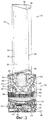
на фиг.3 - вентилятор устройства, показанного на фиг.1, вид сбоку в разрезе;figure 3 is a fan of the device shown in figure 1, a side view in section;
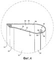
на фиг.4 - часть сопла вентилятора устройства, показанного на фиг.1, увеличенный вид в разрезе;figure 4 - part of the nozzle of the fan of the device shown in figure 1, an enlarged view in section;
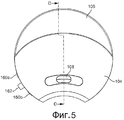
на фиг.5 - увлажнитель устройства, показанного на фиг.1, вид сверху;figure 5 - humidifier of the device shown in figure 1, a top view;
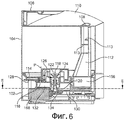
на фиг.6 - увлажнитель, вид сбоку в разрезе вдоль линии D-D, показанной на фиг.5;Fig.6 is a humidifier, a side view in section along the line D-D shown in Fig.5;
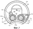
на фиг.7 - основание увлажнителя, показанного на фиг.5, вид сверху;in Fig.7 - the base of the humidifier shown in Fig.5, a top view;
на фиг.8 - увлажнитель, вид сверху в разрезе вдоль линии Е-Е, показанной на фиг.6;on Fig - humidifier, a top view in section along the line EE shown in Fig.6;
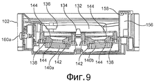
на фиг.9 - основание увлажнителя, вид сбоку в разрезе вдоль линии J-J, показанной на фиг.7;in Fig.9 - the base of the humidifier, a side view in section along the line J-J shown in Fig.7;
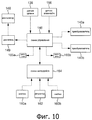
на фиг.10 схематично показана система управления увлажнителя;figure 10 schematically shows the control system of the humidifier;
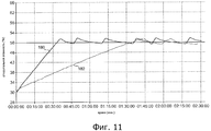
на фиг.11 показана графическая иллюстрация изменения во времени относительной влажности, определяемой датчиком увлажняющего устройства, показанного на фиг.1.figure 11 shows a graphical illustration of the change in time relative humidity determined by the sensor of the humidifying device shown in figure 1.
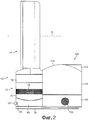
На фиг.1 и 2 показан пример увлажняющего устройства, которое содержит вентилятор 10 и увлажнитель 100, расположенный сзади вентилятора 10. Вентилятор 10, предпочтительно, является безлопастным вентилятором, содержащим опору 12 и сопло 14, установленное на опоре 12 и опирающееся на нее. Опора 12 содержит, по существу, цилиндрический внешний корпус 16, имеющий множество входных отверстий для воздуха в виде решетки 18, которая образована во внешнем корпусе 16 и через которую первичный воздушный поток затягивается в опору 12 из внешней среды. Опора 12 дополнительно содержит множество управляемых пользователем кнопок 20 и управляемый пользователем регулятор 22 для управления работой вентилятора 10. В данном примере опора 12 имеет высоту, составляющую от 200 до 300 мм, а наружный корпус 16 имеет внешний диаметр, составляющий от 100 до 200 мм.Figures 1 and 2 show an example of a humidifier device that includes a
Сопло 14 имеет кольцеобразную форму и определяет центральное отверстие 24. Сопло 14 имеет высоту в диапазоне от 200 до 400 мм. Сопло 14 содержит выпускной участок 26, расположенный в задней части вентилятора 10 и предназначенный для выпуска воздуха из вентилятора 10 и через отверстие 24. Выпускной участок 26 проходит, по меньшей мере частично, вокруг отверстия 24. Внутренняя периферия сопла 14 содержит поверхность 28 Коанда, прилегающую к выпускному участку 26, который направляет выпускаемый из вентилятора 10 воздух поверх указанной поверхности; расширяющуюся поверхность 30, расположенную по потоку после поверхности 28 Коанда; и направляющую поверхность 32, расположенную по потоку после расширяющейся поверхности 30. Расширяющаяся поверхность 30 расположена по конусу от центральной оси Х отверстия 24 таким образом, чтобы способствовать течению потока воздуха, выходящего из вентилятора 10. Угол, образованный расширяющейся поверхностью 30 и центральной осью Х отверстия 24, составляет от 5 до 25°, а в данном примере - около 15°. Направляющая поверхность 32 расположена под углом к расширяющейся поверхности 30 для дополнительного содействия эффективной доставке охлаждающего воздушного потока от вентилятора 10. Направляющая поверхность 32, предпочтительно, расположена, по существу, параллельно центральной оси Х отверстия 24, чтобы представлять собой, по существу, плоскую и, по существу, гладкую поверхность для воздушного потока, выпускаемого из выпускного участка 26. По потоку после направляющей поверхности 32 расположена визуально привлекательная коническая поверхность 34, которая заканчивается концевой поверхностью 36, лежащей практически перпендикулярно центральной оси Х отверстия 24. Угол, образованный конической поверхностью 34 и центральной осью Х отверстия 24, предпочтительно, составляет около 45°. Общая глубина сопла 24 в направлении вдоль центральной оси Х отверстия 24 составляет от 100 до 150 мм, и в данном примере равна примерно 110 мм.The
На фиг.3 показан вид в разрезе вентилятора 10. Опора 12 содержит основание, образованное нижним элементом 38 основания и верхним элементом 40 основания, установленным на нижнем элементе 38 основания, и основную часть 42, установленную на основании. Нижний элемент 38 основания имеет практически плоскую донную поверхность 43. Верхний элемент 40 основания вмещает контроллер 44 для управления работой вентилятора 10 в ответ на нажатие управляемых пользователем кнопок 20, показанных на фиг.1 и 2, и/или в ответ на управление пользователем работой устройства с помощью регулятора 22. Нижний элемент 38 основания может вмещать колебательный механизм 46 для создания колебаний верхнего элемента 40 основания и основной части 42 относительно нижнего элемента 38 основания. Амплитуда каждого колебательного цикла основной части 42, предпочтительно, составляет от 60 до 120°, а в данном примере - около 90°. В данном примере колебательный механизм 46 может выполнять около 3-5 колебательных циклов в минуту. Кабель 48 сети питания проходит через отверстие, образованное в нижнем элементе 38 основания для подачи электрической энергии к вентилятору 10.FIG. 3 shows a cross-sectional view of a
Основная часть 42 опоры 12 имеет открытый верхний конец, к которому присоединяется сопло 14, например, с помощью защелкивающегося соединения. Основная часть 42 вмещает крыльчатку 52, предназначенную для всасывания первичного воздушного потока через отверстия решетки 18 в опору 12. Предпочтительно, чтобы крыльчатка 52 имела форму крыльчатки с косым потоком. Крыльчатка 52 соединена с вращающимся валом 54, выходящим из двигателя 56. В данном примере двигатель 56 является бесщеточным двигателем постоянного тока, скорость вращения которого может управляться контроллером 44 в ответ на управление пользователем работой устройства через регулятор 22. Кабель 57 соединяет контроллер 44 с двигателем 56. Максимальная скорость вращения двигателя 56, предпочтительно, находится в диапазоне от 5000 до 10000 об/мин. Двигатель 56 расположен внутри кожуха двигателя, содержащего верхнюю часть 58, соединенную с нижней частью 60. Одна из этих частей, либо верхняя часть 58, либо нижняя часть 60 кожуха двигателя содержит диффузор 62 в виде неподвижного диска, имеющего спиральные лопасти, который расположен по потоку после крыльчатки 52.The
Кожух двигателя расположен внутри корпуса 64 крыльчатки и установлен на нем. Корпус 64 крыльчатки, в свою очередь, установлен на множестве разнесенных на некотором угловом расстоянии друг от друга опор 66, в данном примере на трех опорах, размещенных внутри основной части 42 опоры 12. Внутри корпуса 64 крыльчатки расположен кожух 68, имеющий в основном форму усеченного конуса. Кожух 68 имеет такую форму, чтобы внешние края крыльчатки 52 были расположены достаточно близко к внутренней поверхности кожуха 68, но не контактировали с ней. К дну корпуса 64 крыльчатки присоединен впускной элемент 70, имеющий практически кольцеобразную форму и предназначенный для направления первичного воздушного потока в корпус 64 крыльчатки. Предпочтительно опора 12 дополнительно содержит шумопоглощающий пеноматериал, предназначенный для уменьшения распространения шума из опоры 12. В данном примере основная часть 42 опоры 12 содержит дискообразный элемент 72, выполненный из пеноматериала и направленный к основанию основной части 42, и по существу кольцеобразный элемент 74, выполненный из пеноматериала и расположенный в кожухе двигателя.The engine cover is located inside the
На фиг.4 показан вид в разрезе сопла 14. Сопло 14 содержит кольцеобразную внешнюю корпусную часть 80, присоединенную к кольцеобразной внутренней корпусной части 82, и окружающую ее. Каждая из этих частей может быть образована множеством соединенных деталей, но в данном варианте осуществления изобретения как внешняя корпусная часть 80, так и внутренняя корпусная часть 82 выполнены в виде единой литой детали. Внутренняя корпусная часть 82 определяет центральное отверстие 24 сопла 14 и имеет внешнюю периферийную поверхность 84, которая имеет такую форму, чтобы определять поверхность 28 Коанда, расширяющуюся поверхность 30, направляющую поверхность 32 и коническую поверхность 34.Figure 4 shows a sectional view of the
Внешняя корпусная часть 80 и внутренняя корпусная часть 82 вместе определяют кольцеобразный внутренний канал 86 сопла 14. Таким образом, внутренний канал 86 проходит вокруг отверстия 24. Внутренний канал 86 ограничен внутренней периферийной поверхностью 88 внешней корпусной части 80 и внутренней периферийной поверхностью 90 внутренней корпусной части 82. Внешняя корпусная часть 80 содержит основание 92, которое присоединяется к открытому верхнему концу основной части 42 опоры 12, например с помощью защелкивающегося соединения, и находится над ней. Основание 92 внешней корпусной части 80 имеет отверстие, через которое первичный воздушный поток входит во внутренний канал 86 сопла 14 из открытого верхнего конца основной части 42 опоры 12.The
Выпускной участок 26 сопла 14 расположен в задней части вентилятора 10. Выпускной участок 26 образован путем перекрытия частей 94, 96 внутренней периферийной поверхности 88 внешней корпусной части 80 и внешней периферийной поверхности 84 внутренней корпусной части 82. В данном примере выпускной участок 26 является практически кольцеобразным и, как показано на фиг.4, имеет, по существу, U-образное поперечное сечение в разрезе по линии, проходящей диаметрально через сопло 14. В данном примере перекрывающиеся участки 94, 96 внутренней периферийной поверхности 88 внешней корпусной части 80 и внешней периферийной поверхности 84 внутренней корпусной части 82 имеют такую форму, что выпускной участок 26 сужается по направлению к выпускному отверстию 98, предназначенному для направления первичного воздушного потока поверх поверхности 28 Коанда. Выпускное отверстие 98 имеет форму кольцеобразной щели предпочтительно относительно постоянной ширины, составляющей от 0,5 до 5 мм. В данном примере выпускное отверстие 98 имеет ширину около 1,0 мм. Вокруг выпускного участка 26 могут быть расположены разделители, предназначенные для отделения друг от друга перекрывающихся участков 94, 96 внутренней периферийной поверхности 88 внешней корпусной части 80 и внешней периферийной поверхности 84 внутренней корпусной части 82 с целью поддержания ширины выпускного отверстия 98 на желаемом уровне. Эти разделители могут быть выполнены за одно целое либо с внутренней периферийной поверхностью 88 внешней корпусной части 80, либо с внешней периферийной поверхностью 84 внутренней корпусной части 82.The
Как показано на фиг.1, 2 и 5, увлажнитель 100 содержит основание 102 и водяной бачок 104, съемным образом установленный на основании 102. Емкость водяного бачка 104 предпочтительно составляет от 2 до 4 л. Верхняя поверхность водяного бачка 104 имеет такую форму, чтобы определять рукоятку 106, дающую возможность пользователю поднимать водяной бачок 104 с основания 102 одной рукой. Водяной бачок 104 имеет выпускное отверстие 108 для водяного тумана, выполненное в верхней поверхности 110 водяного бачка 104 для выпуска влажного воздуха или тумана из увлажнителя 100. Как показано на фиг.6, туман перемещается к выпускному отверстию 108 для водяного тумана по каналу 112, проходя через верхнюю часть водяного бачка 104, в результате чего происходит испускание тумана из увлажнителя 100, главным образом, в вертикальном направлении. Внутри канала 112 расположены перегородки 113, чтобы препятствовать испусканию относительно больших водяных капель из увлажнителя 100.As shown in figures 1, 2 and 5, the
Как основание 102, так и водяной бачок 104 содержат вогнутую переднюю часть, имеющую радиус, который примерно равен радиусу внешнего корпуса 16 опоры 12 вентилятора 10. Это позволяет расположить увлажнитель 100 таким образом, чтобы он прилегал к вентилятору 10, а выпускное отверстие 108 для водяного тумана располагалось в непосредственной близости к соплу 14 вентилятора. В данном примере выпускное отверстие 108 для водяного тумана может быть расположено от задней поверхности сопла 14 вентилятора 10 на минимальном расстоянии в диапазоне от 5 до 30 см. Выпускное отверстие 108 для водяного тумана, предпочтительно, расположено прямо позади, и примерно на одном уровне с нижним участком поверхности 28 Коанда сопла 14 вентилятора 10. Если потребуется, увлажнитель 100 может быть установлен на опоре (не показана), чтобы поднять выпускное отверстие 108 для водяного тумана на один уровень с самым нижним участком поверхности 28 Коанда сопла 14.Both the
Водяной бачок 104 имеет нижнюю поверхность 114, к которой присоединено с возможностью съема горлышко 116, например с помощью резьбового соединения. В данном примере водяной бачок 104 заполняется путем его съема с основания 102, при этом водяной бачок 104 переворачивается таким образом, что горлышко 116 выступает по направлению вверх. Затем горлышко 116 отвинчивается от нижней поверхности 114 водяного бачка 104, и вода вводится в водяной бачок 104 через отверстие, открывающееся при отсоединении горлышка 116 от нижней поверхности 114 водяного бачка 104. Как только водяной бачок 104 наполнился, пользователь вновь подсоединяет горлышко 116 к нижней поверхности 114 водяного бачка 104, вновь переворачивает водяной бачок 104 и возвращает водяной бачок 104 на основание 102. Внутри горлышка 116 расположен подпружиненный клапан 118 для предотвращения утечки воды через выпускное отверстие 120 горлышка 116, когда водяной бачок заново переворачивается. Клапан 118 смещен по направлению к положению, в котором юбка 122 клапана 118 входит в контакт с верхней поверхностью горлышка 116 для предотвращения попадания воды во входное отверстие 124 для воды горлышка 116 водяного бачка 104.The
К горлышку 116 присоединена с возможностью отсоединения, например, с помощью резьбового соединения, кассета 126 для умягчения воды. Кассета 126 может содержать ионообменную смолу, пороговый химреагент-ингибитор, такой как полифосфат, или другие средства, воздействующие на осаждение накипи. Кассета 126 определяет извилистую линию, обозначенную буквой Р на фиг.6, вдоль которой протекает вода, когда она проходит из водяного бачка 104 к горлышку 116, для увеличения продолжительности обработки воды внутри кассеты 126. В верхней поверхности кассеты 126 могут быть выполнены отверстия, чтобы позволить воздуху внутри кассеты 126 вытесняться оттуда при поступлении воды в кассету 126 из водяного бачка 104.Connected to the
Как показано на фиг.7-9, основание 102 содержит верхнюю поверхность 128. Верхняя поверхность 128 основания 102 содержит углубленный участок 130, который определяет водяной резервуар 132 для приема воды из водяного бачка 104. Выступ 134, проходящий вверх от углубленного участка 130 верхней поверхности 128, выступает в горлышко 116, когда водяной бачок 104 установлен на основании 102. Выступ 134 толкает клапан 118 в направлении вверх, чтобы открывать горлышко 116, таким образом позволяя воде под воздействием силы тяжести проходить в водяной резервуар 132 из водяного бачка 104. В результате водяной резервуар 132 наполняется водой до уровня, который, по существу, находится в одной плоскости с верхней поверхностью выступа 134. Внутри водяного резервуара 132 расположен магнитный датчик 136 уровня для определения уровня воды в водяном резервуаре 132.As shown in Figs. 7-9, the
Углубленный участок 130 верхней поверхности 128 имеет два отверстия 138, каждое из которых позволяет воздействовать на поверхность соответствующего пьезоэлектрического преобразователя 140а, 140b, которые расположены под верхней поверхностью 128 основания 102 для распыления воды, находящейся в водяном резервуаре 132. Кольцеобразный металлический теплоотводящий радиатор 142, расположенный между основанием 102 и каждым из преобразователей 140а, 140b, служит для передачи тепла от преобразователя к воде, находящейся в водяном резервуаре 132. Каждый теплоотводящий радиатор 142 имеет коническую верхнюю поверхность 144 для увеличения степени распыления воды преобразователями 140а, 140b. Степень распыления дополнительно увеличивается благодаря наклону верхних поверхностей преобразователей 140а, 140b на угол в диапазоне от 5 до 10° к горизонтали. Кольцеобразный изолирующий элемент 144 образует водонепроницаемую изоляцию между каждым из преобразователей 140а, 140b и теплоотводящим радиатором 142. Под верхней поверхностью 128 основания 102 расположена схема 146 управления для возбуждения ультразвуковых колебаний преобразователей 140а, 140b с целью распыления воды внутри водяного резервуара 132. Как показано на фиг.10, схема 146 управления может быть настроена на прием сигнала от датчика 136 уровня, который показывает уровень воды в водяном резервуаре 132 при падении уровня ниже минимального. В ответ на этот сигнал схема 146 управления завершает возбуждение датчиков 140а, 140b.The recessed
Основание 102 дополнительно содержит вентилятор 148 с приводом от двигателя для создания воздушного потока через увлажнитель 100, расход которого предпочтительно составляет от 1 до 2 л/с. Схема 146 управления, предпочтительно, управляет приведением в действие и скоростью двигателя 149 для привода вентилятора 148. Вентилятор 148 расположен внутри корпуса 150 вентилятора, образованного в основании 102 увлажнителя 100. Корпус 150 вентилятора имеет впускное отверстие для воздуха в виде множества отверстий 152, выполненных в боковой стенке основания 102, через которые воздушный поток втягивается в корпус 150 вентилятора благодаря вращению вентилятора 148, и выпускное отверстие 154 для воздуха, через которое воздушный поток проходит в воздушный канал 156, расположенный на одной из сторон водяного резервуара 132. На верхней периферии воздушного канала 156 расположены отверстия 158 для испускания воздушного потока из воздушного канала на уровне, который находится выше максимального уровня для воды, находящейся в водяном резервуаре 132, чтобы воздушный поток, выпускаемый из воздушного канала 156, проходил над поверхностью воды, содержащейся в водяном резервуаре 132, до входа в канал 112 водяного бачка 102.The base 102 further comprises a motor-driven
Пользовательский интерфейс для управления работой увлажнителя 100 расположен на боковой стенке основания 102. В данном примере пользовательский интерфейс содержит множество управляемых пользователем кнопок 160а, 160b и управляемый пользователем регулятор 162. Регулятор 162 может управляться пользователем для установки желаемого уровня относительной влажности окружающей среды, в которой расположено увлажняющее устройство, такой как комната, офис или другое бытовое помещение. Например, желаемый уровень относительной влажности может быть выбран в диапазоне от 30 до 80% при 20°С с помощью управления регулятором 162. Одна из кнопок 160а - это кнопка включения/выключения увлажнителя 100, тогда как другая кнопка 160b может быть нажата для ручной коррекции настроек, чтобы увлажнитель 100 продолжал работать до того момента, когда водяной бачок 102 опустеет. Пользовательский интерфейс дополнительно содержит схему 164 пользовательского интерфейса, которая выдает управляющие сигналы схеме 146 управления, указывающей угловое положение регулятора 162 и нажатие одной из кнопок 160, которая также принимает управляющие сигналы, выходящие от схемы 146 управления. Пользовательский интерфейс может также содержать один или несколько светодиодов (как показано на фиг.10) для обеспечения визуального тревожного сигнала, в зависимости от состояния увлажнителя 100. Например, светодиод 165а может зажигаться схемой 146 управления, показывая, что запасы воды в водяном бачке 104 истощаются, на что указывает сигнал, принятый схемой 146 управления от датчика 136 уровня.A user interface for controlling the operation of the
Увлажнитель 100 дополнительно содержит датчик 166 влажности для определения относительной влажности воздуха внешней среды и для подачи сигнала, обозначающего определенную им относительную влажность, в схему 146 управления. В данном примере датчик 166 влажности расположен непосредственно за отверстиями 152, выполненными в боковой стенке основания 102, для определения относительной влажности воздушного потока, втягиваемого в основание 102 увлажнителя 100 вентилятором 148. Пользовательский интерфейс может содержать светодиод 165b, который зажигается схемой 146 управления, когда выходной сигнал от датчика 166 влажности показывает, что относительная влажность воздушного потока, входящего в основание 102, находится на желаемом уровне относительной влажности, установленном пользователем, или выше него.The
Увлажнитель 100 также содержит блок 168 питания для подачи питания к различным электрическим элементам увлажнителя 100, в том числе к схеме 146 управления, к двигателю для приведения в действие вентилятора 148 и к схеме 164 пользовательского интерфейса. Питающий кабель (не показан) от электросети проходит через отверстие, выполненное в основании 102, для подачи электрического питания блоку 168 питания.
Далее будет описана работа увлажняющего устройства.Next, the operation of the humidifying device will be described.
Для управления вентилятором 10 пользователь нажимает одну из соответствующих кнопок 20, расположенных на опоре 12 вентилятора 10. В результате этого действия контроллер 44 приводит в действие двигатель 56 для вращения крыльчатки 52. Вращение крыльчатки 52 вызывает втягивание первичного воздушного потока в опору 12 вентилятора 10 через решетку 18. Первичный воздушный поток проходит последовательно через корпус 64 крыльчатки и отверстие, выполненное в основании 92 внешней корпусной части 80 сопла 14, чтобы войти во внутренний канал 86 сопла 14. Внутри сопла 14 первичный воздушный поток разделяется на два воздушных потока, которые проходят в противоположных направлениях вокруг центрального отверстия 24 сопла 14. Поскольку воздушные потоки протекают через внутренний канал 86, воздух входит в выпускной участок 26 сопла 14. Воздушный поток в выпускном участке 26, предпочтительно, является практически равномерным вокруг отверстия 24 сопла 14. Внутри каждой части выпускного участка 26 направление части воздушного потока, по существу, реверсировано. Часть воздушного потока сжимается конической частью выпускной участка 26 и выпускается через выпускное отверстие 98.To control the
Первичный воздушный поток, выпускаемый из выпускного участка 26, направляется поверх поверхности 28 Коанда сопла 14, вызывая вторичный воздушный поток, создаваемый захватываемым из внешней среды воздухом, особенно из области вокруг выпускного отверстия 98 выпускного участка 26 и из области вокруг задней части сопла 14. Этот вторичный воздушный поток проходит через центральное отверстие 24 сопла 14, где он смешивается с первичным воздушным потоком, чтобы образовать общий воздушный поток, или течение воздуха, выталкиваемое вперед из сопла 14. В зависимости от скорости вращения двигателя 56 удельный массовый расход воздушного потока, выталкиваемого вперед из вентилятора 10, может достигать 400 л/с, предпочтительно - 600 л/с.The primary air stream discharged from the
Равномерное распространение первичного воздушного потока вдоль выпускного участка 26 сопла 14 гарантирует, что воздушный поток проходит равномерно над расширяющейся поверхностью 30. Расширяющаяся поверхность 30 вызывает уменьшение средней скорости воздушного потока за счет перемещения воздушного потока через область управляемого расширения. Относительно небольшой угол наклона расширяющейся поверхности 30 к центральной оси Х отверстия 24 позволяет расширять воздушный поток постепенно. В противном случае резкое и быстрое расхождение приведет к тому, что в воздушном потоке будут разрывы, что будет создавать вихри в области расширения. Такие вихри могут привести к увеличению турбулентности и связанному с ней шуму в воздушном потоке, который может быть нежелательным, особенно в устройстве для домашнего применения, таком как вентилятор. Воздушный поток, выталкиваемый вперед за расширяющуюся поверхность 30, может иметь тенденцию к продолжению расхождения. Присутствие направляющей поверхности 32, проходящей, по существу, параллельно центральной оси Х отверстия 30, дополнительно сужает воздушный поток. В результате воздушный поток может эффективно перемещаться от сопла 14, создавая возможность быстро ощутить увлажненный воздушный поток на расстоянии в несколько метров от вентилятора 10.The uniform distribution of the primary air flow along the
При работе вентилятора 10 пользователь может включить увлажнитель 100, нажав на соответствующую кнопку 160а пользовательского интерфейса увлажнителя 100. В ответ на нажатие кнопки 160а схема 146 управления приводит в действие двигатель 149 для вращения вентилятора 148 с целью создания воздушного потока через увлажнитель 100. Одновременно с запуском двигателя 149 вентилятора 148 схема 146 управления приводит в действие вибрирование обоих преобразователей 140а, 140b, предпочтительно с частотой в диапазоне от 1 до 2 МГц, для распыления воды, имеющейся внутри водяного резервуара 132. Это создает водяные капли, находящиеся в воздухе над водой, содержащийся внутри водяного резервуара 132. Поскольку вода в водяном резервуаре 132 распыляется, водяной резервуар 132 постоянно пополняется водой из водяного бачка 104, поэтому уровень воды внутри водяного резервуара 132 остается практически постоянным, в то время как уровень воды внутри водяного бачка 104 постепенно падает.When the
При вращении вентилятора 148 воздушный поток втягивается в увлажнитель 100 через отверстия 152, сформированные в боковой стенке основания 102. Воздушный поток проходит через корпус 150 вентилятора и попадает в воздушный канал 156, из которого выпускается через отверстия 158. Воздушный поток проходит над водой, находящейся в водяном резервуаре 132, при этом находящиеся в воздухе водяные капли входят в создаваемый вентилятором 148 воздушный поток и увлекаются с этим воздушным потоком. Увлажненный воздушный поток проходит в направлении вверх через горлышко 112 и выпускается из выпускного отверстия 108 для водяного тумана в виде дымки или тумана. Этот туман вытягивается через центральное отверстие 24 сопла 14 как часть вторичного воздушного потока, создаваемого при выпускании первичного воздушного потока из выпускного участка 26 сопла 14. Следовательно, туман перемещается на некоторое расстояние от увлажнителя 100 в воздушном потоке, создаваемом вентилятором 10, таким образом создавая возможность быстро ощутить увлажненный воздушный поток на расстоянии в несколько метров от увлажнителя 100. Благодаря покачиванию основной части 42 опоры 12 и, следовательно, покачиванию сопла 14 относительно увлажнителя 100, этот влажный воздушный поток может распространяться в форме дуги в диапазоне от 60 до 120°, предпочтительно около 90°, для быстрого увеличения рассеивания влажного воздуха во внешней окружающей среде.When the
В том случае, если кнопка 160b не была нажата, увлажненный воздушный поток выпускается из увлажнителя 100 до тех пор, пока относительная влажность воздушного потока, входящего в увлажнитель 100, как влажность, определяемая датчиком 166 влажности, не будет составлять при 20°С на 1% выше, чем уровень относительной влажности, выбранный пользователем с помощью регулятора 162. В данном случае испускание увлажненного воздушного потока из увлажнителя 100 прекращается схемой 146 управления посредством прекращения подачи управляющих сигналов преобразователям 140а, 140b. В качестве необязательной меры двигатель 149 также может быть остановлен для того, чтобы воздушный поток не выпускался из увлажнителя 100, но когда датчик 166 влажности расположен в непосредственной близости к двигателю 149, как в данном примере, то предпочтительно, чтобы двигатель 149 постоянно работал, чтобы избежать нежелательных колебаний температуры в локальном окружении датчика 166 влажности. Когда датчик 166 влажности расположен, например, снаружи от увлажнителя 100, двигатель 149 также может быть остановлен, когда относительная влажность воздуха локальной окружающей среды около датчика 166 влажности при 20°С будет на 1% выше уровня относительной влажности, выбранного пользователем.In the event that the
В результате прекращения испускания увлажненного воздушного потока из увлажнителя 100 относительная влажность, определяемая датчиком 166 влажности, начнет падать. Как только относительная влажность воздуха локальной окружающей среды вблизи датчика 166 влажности упала при 20°С на 1% ниже уровня относительной влажности, выбранного пользователем, схема 146 управления подает запускающие сигналы к выбранному одному из преобразователей, например преобразователю 140а, чтобы заново начать испускание увлажненного воздушного потока из увлажнителя 100. Как и до этого, увлажненный воздушный поток испускается из увлажнителя 100 до тех пор, пока относительная влажность, определяемая датчиком 166 влажности, снова не будет при 20°С на 1% выше, чем уровень относительной влажности, выбранный пользователем, в этот момент работа преобразователя 140а прекращается. Как только относительная влажность воздуха локальной окружающей среды вблизи датчика 166 влажности снова упала при 20°С на 1% ниже уровня относительной влажности, выбранного пользователем, схема 146 управления подает запускающие сигналы к другому преобразователю, например преобразователю 140b, чтобы заново начать испускание увлажненного воздушного потока из увлажнителя 100. И вновь увлажненный воздушный поток испускается из увлажнителя 100 до того момента, пока относительная влажность, определяемая датчиком 166 влажности, не будет при 20°С на 1% выше, чем уровень относительной влажности, выбранный пользователем, в этот момент приведение в действие преобразователя 140b прекращается.As a result of stopping the emission of the humidified air stream from the
Эта последовательность поочередного приведения в действие преобразователей 140а, 140b для поддержания определяемого уровня влажности около уровня, выбранного пользователем, продолжается до тех пор, пока не будет нажата кнопка 160а, отключающая увлажнитель 100, или до тех пор, пока не будет принят сигнал от датчика 136 уровня, указывающий на то, что уровень воды в водяном резервуаре 132 упал до минимального уровня.This sequence of alternately actuating the
Относительная влажность, определяемая датчиком 166 влажности, таким образом, поддерживается около уровня, выбранного пользователем с помощью регулятора 162, с помощью последовательного приведения в действие сокращенного количества n2 преобразователей (один) по сравнению с количеством n1 преобразователей (два), используемых изначально, для увеличения относительной влажности во внешней среде до выбранного уровня. Преимущество, связанное с приведением в действие большего количества преобразователей, чтобы изначально увеличить относительную влажность во внешней среде до выбранного уровня, показано на фиг.11. На фиг.11 дана графическая иллюстрация изменения по времени определяемой относительной влажности для двух режимов работы увлажняющего устройства. В первом режиме оба преобразователя 140а, 140b приведены в действие изначально для увеличения относительной влажности до 50% при 20°С. Во втором режиме только преобразователь 140а изначально приведен в действие для увеличения относительной влажности до 50% при 20°С. Изменение определяемой относительной влажности со временем для первого режима показано линией 180 на фиг.11, в то время как изменение определяемой относительной влажности со временем для второго режима показано линией 182 на фиг.11. Как можно увидеть из фиг.11, время, требуемое для того, чтобы определяемая относительная влажность увеличилась с базового уровня около 30% при 20°С до заданного уровня, значительно короче, когда оба преобразователя 140а, 140b использовались для увеличения относительной влажности до 50% при 20°С.The relative humidity detected by the
В качестве альтернативы приведения в действие сокращенного количества n2 преобразователей для поддержания определяемой относительной влажности около заданного уровня, то же самое количество n1 преобразователей (два), используемых изначально для увеличения относительной влажности в окружающей среде до выбранного уровня, может также использоваться для поддержания определяемой относительной влажности около заданного уровня. В данном случае продолжительность приведения в действие n1 преобразователей с того момента, когда определяемая относительная влажность воздуха окружающей среды вблизи датчика 166 влажности упала при 20°С на 1% ниже уровня относительной влажности, до того момента, когда относительная влажность, определяемая датчиком 166 влажности, стала при 20°С на 1% выше уровня влажности, выбранного пользователем, является более коротким, чем в случае использования сокращенного количества n2 преобразователей для поддержания определяемой относительной влажности около заданного уровня. Обратившись снова к фиг.11, можно увидеть, что в первом режиме работы оба преобразователя 140а, 140b приведены в действие для поддержания определяемой относительной влажности около заданного уровня, в то время как во втором режиме работы только один преобразователь используется для поддержания определяемой относительной влажности около заданного уровня. Как и в том случае, когда сокращенное количество n2 преобразователей используется для поддержания определяемой относительной влажности около заданного уровня, это может продлить срок службы преобразователей 140а, 140b.As an alternative to driving a reduced number of n 2 transducers to maintain a determined relative humidity around a given level, the same number of n 1 transducers (two) used initially to increase the relative humidity in the environment to a selected level can also be used to maintain a determined relative humidity around a given level. In this case, the duration of the activation of n 1 transducers from the moment when the determined relative humidity of the ambient air near the
Claims (15)
Applications Claiming Priority (5)
| Application Number | Priority Date | Filing Date | Title |
|---|---|---|---|
| GB0903690A GB2468328A (en) | 2009-03-04 | 2009-03-04 | Fan assembly with humidifier |
| GB0903690.6 | 2009-03-04 | ||
| GB0915033A GB2473037A (en) | 2009-08-28 | 2009-08-28 | Humidifying apparatus comprising a fan and a humidifier with a plurality of transducers |
| GB0915033.5 | 2009-08-28 | ||
| PCT/GB2010/050283 WO2010100462A1 (en) | 2009-03-04 | 2010-02-18 | Humidifying apparatus |
Publications (2)
| Publication Number | Publication Date |
|---|---|
| RU2011136841A RU2011136841A (en) | 2013-03-10 |
| RU2511503C2 true RU2511503C2 (en) | 2014-04-10 |
Family
ID=42342606
Family Applications (1)
| Application Number | Title | Priority Date | Filing Date |
|---|---|---|---|
| RU2011136841/12A RU2511503C2 (en) | 2009-03-04 | 2010-02-18 | Moistening device |
Country Status (10)
| Country | Link |
|---|---|
| US (2) | US8356804B2 (en) |
| EP (1) | EP2414738B1 (en) |
| JP (2) | JP5260582B2 (en) |
| KR (1) | KR101290625B1 (en) |
| CN (2) | CN202056982U (en) |
| AU (2) | AU2010220190B2 (en) |
| CA (1) | CA2746560C (en) |
| ES (1) | ES2437740T3 (en) |
| RU (1) | RU2511503C2 (en) |
| WO (1) | WO2010100462A1 (en) |
Families Citing this family (169)
| Publication number | Priority date | Publication date | Assignee | Title |
|---|---|---|---|---|
| GB2452593A (en) * | 2007-09-04 | 2009-03-11 | Dyson Technology Ltd | A fan |
| GB2463698B (en) * | 2008-09-23 | 2010-12-01 | Dyson Technology Ltd | A fan |
| GB2464736A (en) | 2008-10-25 | 2010-04-28 | Dyson Technology Ltd | Fan with a filter |
| GB2466058B (en) * | 2008-12-11 | 2010-12-22 | Dyson Technology Ltd | Fan nozzle with spacers |
| CA2746496C (en) | 2009-03-04 | 2012-12-04 | Dyson Technology Limited | A fan assembly |
| KR101370271B1 (en) | 2009-03-04 | 2014-03-04 | 다이슨 테크놀러지 리미티드 | fan |
| GB2468317A (en) | 2009-03-04 | 2010-09-08 | Dyson Technology Ltd | Height adjustable and oscillating fan |
| GB2468320C (en) | 2009-03-04 | 2011-06-01 | Dyson Technology Ltd | Tilting fan |
| EP2414738B1 (en) | 2009-03-04 | 2013-10-09 | Dyson Technology Limited | Humidifying apparatus |
| GB2468331B (en) | 2009-03-04 | 2011-02-16 | Dyson Technology Ltd | A fan |
| GB2468329A (en) | 2009-03-04 | 2010-09-08 | Dyson Technology Ltd | Fan assembly |
| GB2468315A (en) | 2009-03-04 | 2010-09-08 | Dyson Technology Ltd | Tilting fan |
| GB2476171B (en) | 2009-03-04 | 2011-09-07 | Dyson Technology Ltd | Tilting fan stand |
| GB2468325A (en) * | 2009-03-04 | 2010-09-08 | Dyson Technology Ltd | Height adjustable fan with nozzle |
| GB2468323A (en) | 2009-03-04 | 2010-09-08 | Dyson Technology Ltd | Fan assembly |
| AU2010219495B2 (en) | 2009-03-04 | 2011-11-10 | Dyson Technology Limited | A fan |
| GB2468312A (en) | 2009-03-04 | 2010-09-08 | Dyson Technology Ltd | Fan assembly |
| GB0903682D0 (en) | 2009-03-04 | 2009-04-15 | Dyson Technology Ltd | A fan |
| GB2468326A (en) | 2009-03-04 | 2010-09-08 | Dyson Technology Ltd | Telescopic pedestal fan |
| GB0919473D0 (en) | 2009-11-06 | 2009-12-23 | Dyson Technology Ltd | A fan |
| GB2478925A (en) | 2010-03-23 | 2011-09-28 | Dyson Technology Ltd | External filter for a fan |
| GB2478927B (en) | 2010-03-23 | 2016-09-14 | Dyson Technology Ltd | Portable fan with filter unit |
| ES2553148T3 (en) | 2010-05-27 | 2015-12-04 | Dyson Technology Limited | Air blowing device by means of a narrow slit nozzle assembly |
| GB2482548A (en) | 2010-08-06 | 2012-02-08 | Dyson Technology Ltd | A fan assembly with a heater |
| GB2482549A (en) | 2010-08-06 | 2012-02-08 | Dyson Technology Ltd | A fan assembly with a heater |
| GB2482547A (en) | 2010-08-06 | 2012-02-08 | Dyson Technology Ltd | A fan assembly with a heater |
| GB2483448B (en) | 2010-09-07 | 2015-12-02 | Dyson Technology Ltd | A fan |
| US10100836B2 (en) | 2010-10-13 | 2018-10-16 | Dyson Technology Limited | Fan assembly |
| GB2484670B (en) | 2010-10-18 | 2018-04-25 | Dyson Technology Ltd | A fan assembly |
| WO2012052735A1 (en) | 2010-10-18 | 2012-04-26 | Dyson Technology Limited | A fan assembly |
| JP5778293B2 (en) | 2010-11-02 | 2015-09-16 | ダイソン テクノロジー リミテッド | Blower assembly |
| GB2486019B (en) | 2010-12-02 | 2013-02-20 | Dyson Technology Ltd | A fan |
| GB2486890B (en) | 2010-12-23 | 2017-09-06 | Dyson Technology Ltd | A fan |
| GB2486892B (en) | 2010-12-23 | 2017-11-15 | Dyson Technology Ltd | A fan |
| GB2486889B (en) | 2010-12-23 | 2017-09-06 | Dyson Technology Ltd | A fan |
| TWD146515S (en) * | 2011-04-22 | 2012-04-11 | 蓋博企業有限公司 | Bladeless fan |
| CN102865257A (en) * | 2011-07-06 | 2013-01-09 | 任文华 | Vaneless fan |
| CN102269459A (en) * | 2011-07-13 | 2011-12-07 | 上海腾邦环境科技有限公司 | Movable spraying unit |
| GB2492963A (en) * | 2011-07-15 | 2013-01-23 | Dyson Technology Ltd | Fan with scroll casing decreasing in cross-section |
| GB2492961A (en) | 2011-07-15 | 2013-01-23 | Dyson Technology Ltd | Fan with impeller and motor inside annular casing |
| GB2492962A (en) | 2011-07-15 | 2013-01-23 | Dyson Technology Ltd | Fan with tangential inlet to casing passage |
| WO2013016227A1 (en) * | 2011-07-22 | 2013-01-31 | Atico International Usa, Inc. | Bladeless misting fan |
| GB2493506B (en) | 2011-07-27 | 2013-09-11 | Dyson Technology Ltd | A fan assembly |
| AU2012288597B2 (en) * | 2011-07-27 | 2015-04-09 | Dyson Technology Limited | A fan assembly |
| AU2012216658B2 (en) | 2011-09-13 | 2016-09-15 | Black & Decker Inc | Method of reducing air compressor noise |
| US8899378B2 (en) | 2011-09-13 | 2014-12-02 | Black & Decker Inc. | Compressor intake muffler and filter |
| CN102338133A (en) * | 2011-09-30 | 2012-02-01 | 东莞市旭尔美电器科技有限公司 | A bladeless fan |
| GB201119500D0 (en) | 2011-11-11 | 2011-12-21 | Dyson Technology Ltd | A fan assembly |
| GB2496877B (en) | 2011-11-24 | 2014-05-07 | Dyson Technology Ltd | A fan assembly |
| CN102661268A (en) * | 2011-12-29 | 2012-09-12 | 乐清市畅想电器科技有限公司 | Novel non-leaf humidifying fan and method of humidifying |
| FR2985201B1 (en) * | 2012-01-03 | 2016-01-08 | Oreal | HOLLOW DISTRIBUTION HEAD |
| FR2985202A1 (en) * | 2012-01-03 | 2013-07-05 | Oreal | HEAD OF DISTRIBUTION |
| USD678993S1 (en) * | 2012-01-06 | 2013-03-26 | Cute Item Industries, Ltd. | Bladeless hand held fan |
| USD676536S1 (en) * | 2012-01-19 | 2013-02-19 | Atico International Usa, Inc. | Bladeless misting fan |
| GB2498547B (en) | 2012-01-19 | 2015-02-18 | Dyson Technology Ltd | A fan |
| GB2499044B (en) | 2012-02-06 | 2014-03-19 | Dyson Technology Ltd | A fan |
| GB2499041A (en) | 2012-02-06 | 2013-08-07 | Dyson Technology Ltd | Bladeless fan including an ionizer |
| GB2499042A (en) | 2012-02-06 | 2013-08-07 | Dyson Technology Ltd | A nozzle for a fan assembly |
| KR102046476B1 (en) * | 2012-02-29 | 2019-11-19 | 웅진코웨이 주식회사 | Humidification apparatus capable of preventing water leak |
| GB2500012B (en) | 2012-03-06 | 2016-07-06 | Dyson Technology Ltd | A Humidifying Apparatus |
| GB2500017B (en) * | 2012-03-06 | 2015-07-29 | Dyson Technology Ltd | A Humidifying Apparatus |
| GB2500011B (en) * | 2012-03-06 | 2016-07-06 | Dyson Technology Ltd | A Humidifying Apparatus |
| GB2500005B (en) * | 2012-03-06 | 2014-08-27 | Dyson Technology Ltd | A method of generating a humid air flow |
| GB2500010B (en) * | 2012-03-06 | 2016-08-24 | Dyson Technology Ltd | A humidifying apparatus |
| GB2500009B (en) * | 2012-03-06 | 2015-08-05 | Dyson Technology Ltd | A Humidifying Apparatus |
| KR101699293B1 (en) | 2012-03-06 | 2017-01-24 | 다이슨 테크놀러지 리미티드 | A fan assembly |
| GB2500903B (en) | 2012-04-04 | 2015-06-24 | Dyson Technology Ltd | Heating apparatus |
| GB2501301B (en) | 2012-04-19 | 2016-02-03 | Dyson Technology Ltd | A fan assembly |
| GB2502103B (en) | 2012-05-16 | 2015-09-23 | Dyson Technology Ltd | A fan |
| EP2850324A2 (en) | 2012-05-16 | 2015-03-25 | Dyson Technology Limited | A fan |
| GB2532557B (en) | 2012-05-16 | 2017-01-11 | Dyson Technology Ltd | A fan comprsing means for suppressing noise |
| US20130320574A1 (en) * | 2012-05-18 | 2013-12-05 | The Yankee Candle Company, Inc. | Aerodynamic formula dispersing apparatus |
| JP2013242072A (en) * | 2012-05-18 | 2013-12-05 | Iris Ohyama Inc | Humidifying mechanism |
| JP5849869B2 (en) * | 2012-06-26 | 2016-02-03 | 株式会社デンソー | Blower |
| GB2503907B (en) | 2012-07-11 | 2014-05-28 | Dyson Technology Ltd | A fan assembly |
| CN103629086A (en) * | 2012-08-21 | 2014-03-12 | 任文华 | Fan |
| FR2999100B1 (en) * | 2012-12-06 | 2015-01-16 | Seb Sa | REFRESHING DEVICE |
| AU350181S (en) | 2013-01-18 | 2013-08-15 | Dyson Technology Ltd | Humidifier or fan |
| AU350179S (en) | 2013-01-18 | 2013-08-15 | Dyson Technology Ltd | Humidifier or fan |
| BR302013003358S1 (en) | 2013-01-18 | 2014-11-25 | Dyson Technology Ltd | CONFIGURATION APPLIED ON HUMIDIFIER |
| AU350140S (en) | 2013-01-18 | 2013-08-13 | Dyson Technology Ltd | Humidifier or fan |
| GB2510195B (en) | 2013-01-29 | 2016-04-27 | Dyson Technology Ltd | A fan assembly |
| CA2899747A1 (en) * | 2013-01-29 | 2014-08-07 | Dyson Technology Limited | A fan assembly |
| CA152655S (en) | 2013-03-07 | 2014-05-20 | Dyson Technology Ltd | Fan |
| CA152658S (en) | 2013-03-07 | 2014-05-20 | Dyson Technology Ltd | Fan |
| CA152656S (en) | 2013-03-07 | 2014-05-20 | Dyson Technology Ltd | Fan |
| CA152657S (en) | 2013-03-07 | 2014-05-20 | Dyson Technology Ltd | Fan |
| BR302013004394S1 (en) | 2013-03-07 | 2014-12-02 | Dyson Technology Ltd | CONFIGURATION APPLIED TO FAN |
| USD729372S1 (en) | 2013-03-07 | 2015-05-12 | Dyson Technology Limited | Fan |
| FR3007953B1 (en) | 2013-07-04 | 2015-07-24 | Oreal | AEROSOL ALCOHOLIC DEODORANT EQUIPPED WITH A HOLLOW DISTRIBUTION HEAD |
| FR3007952B1 (en) * | 2013-07-04 | 2015-07-24 | Oreal | AEROSOL CONTAINING AN EMULSION DEODORANT EQUIPPED WITH A HOLLOW DISTRIBUTION HEAD |
| GB2530906B (en) | 2013-07-09 | 2017-05-10 | Dyson Technology Ltd | A fan assembly |
| TWD172707S (en) | 2013-08-01 | 2015-12-21 | 戴森科技有限公司 | A fan |
| CA154722S (en) | 2013-08-01 | 2015-02-16 | Dyson Technology Ltd | Fan |
| CA154723S (en) | 2013-08-01 | 2015-02-16 | Dyson Technology Ltd | Fan |
| CN105971904A (en) * | 2013-08-28 | 2016-09-28 | 胡妍 | Safe low-noise electric fan |
| CN106091191A (en) * | 2013-08-28 | 2016-11-09 | 申清章 | A kind of bladeless fan |
| CN105715566A (en) * | 2013-08-28 | 2016-06-29 | 胡妍 | Blade-free double-head fan |
| CN106286397A (en) * | 2013-08-28 | 2017-01-04 | 乐清市华尊电气有限公司 | A kind of safe electric fan that can freeze |
| CN106286399A (en) * | 2013-08-28 | 2017-01-04 | 乐清市华尊电气有限公司 | A kind of electricity cold mould electric fan |
| GB2518638B (en) | 2013-09-26 | 2016-10-12 | Dyson Technology Ltd | Humidifying apparatus |
| KR101706812B1 (en) | 2013-10-02 | 2017-02-14 | 엘지전자 주식회사 | Indoor unit for cassette type air conditoiner |
| KR101702169B1 (en) | 2013-10-02 | 2017-02-02 | 엘지전자 주식회사 | Indoor unit for cassette type air conditoiner |
| KR20150043573A (en) * | 2013-10-11 | 2015-04-23 | 엘지전자 주식회사 | Indoor unit for cassette type air conditoiner |
| JP1518059S (en) | 2014-01-09 | 2015-02-23 | ||
| JP1518058S (en) | 2014-01-09 | 2015-02-23 | ||
| KR101662377B1 (en) | 2014-01-27 | 2016-10-04 | 엘지전자 주식회사 | Indoor unit of air conditoiner |
| US9316405B2 (en) * | 2014-07-10 | 2016-04-19 | Dana Electronics Co., Ltd. | Cyclone type humidifier and wet air purifier combination device using centrifugal force |
| GB2528708B (en) | 2014-07-29 | 2016-06-29 | Dyson Technology Ltd | A fan assembly |
| GB2528704A (en) | 2014-07-29 | 2016-02-03 | Dyson Technology Ltd | Humidifying apparatus |
| GB2528709B (en) | 2014-07-29 | 2017-02-08 | Dyson Technology Ltd | Humidifying apparatus |
| JP6272188B2 (en) * | 2014-08-29 | 2018-01-31 | アイリスオーヤマ株式会社 | Ultrasonic humidifier |
| EP3012547B1 (en) * | 2014-10-24 | 2019-12-04 | LG Electronics Inc. | Air purifier |
| EP3056827A1 (en) * | 2014-11-27 | 2016-08-17 | OC S.r.l. | Ventilation system for a micronizer, in particular for washing machines-sterilizers |
| DE102014017774B4 (en) * | 2014-12-02 | 2018-05-17 | Audi Ag | Method for ventilation of a room and ventilation system |
| USD747451S1 (en) * | 2014-12-19 | 2016-01-12 | Auramist, Inc. | Fan |
| USD753280S1 (en) * | 2014-12-19 | 2016-04-05 | Auramist, Inc. | Fan |
| TWD173929S (en) * | 2015-01-30 | 2016-02-21 | 戴森科技有限公司 | A fan |
| TWD173930S (en) * | 2015-01-30 | 2016-02-21 | 戴森科技有限公司 | A fan |
| TWD173932S (en) * | 2015-01-30 | 2016-02-21 | 戴森科技有限公司 | A fan |
| TWD173931S (en) * | 2015-01-30 | 2016-02-21 | 戴森科技有限公司 | A fan |
| TWD179707S (en) * | 2015-01-30 | 2016-11-21 | 戴森科技有限公司 | A fan |
| TWD173928S (en) * | 2015-01-30 | 2016-02-21 | 戴森科技有限公司 | A fan |
| KR20170024313A (en) | 2015-08-25 | 2017-03-07 | 신재옥 | Apparatus for humid air injection |
| CN106524343A (en) * | 2015-09-15 | 2017-03-22 | 戴赐鹏 | Cleaning system and method for controlling indoor harmful substances |
| US11111913B2 (en) | 2015-10-07 | 2021-09-07 | Black & Decker Inc. | Oil lubricated compressor |
| CN105179999A (en) * | 2015-10-17 | 2015-12-23 | 李陈 | LED flame lamp |
| USD804007S1 (en) * | 2015-11-25 | 2017-11-28 | Vornado Air Llc | Air circulator |
| EP3211337B1 (en) | 2016-02-26 | 2020-09-23 | LG Electronics Inc. | Air cleaner |
| US10518205B2 (en) | 2016-02-26 | 2019-12-31 | Lg Electronics Inc. | Air cleaner |
| EP3910259A1 (en) | 2016-02-26 | 2021-11-17 | LG Electronics Inc. | Air cleaner |
| US10436469B2 (en) | 2016-02-26 | 2019-10-08 | Lg Electronics Inc. | Air cleaner |
| CN111765554B (en) | 2016-02-26 | 2022-02-25 | Lg电子株式会社 | Air cleaner |
| EP3211345B1 (en) | 2016-02-26 | 2020-09-16 | Lg Electronics Inc. | Air cleaner |
| CN111156622B (en) | 2016-02-26 | 2022-04-26 | Lg电子株式会社 | Air cleaner |
| WO2017146354A1 (en) * | 2016-02-26 | 2017-08-31 | 엘지전자 주식회사 | Air purifier |
| EP3211338B1 (en) * | 2016-02-26 | 2020-03-25 | LG Electronics Inc. | Air cleaner and method for controlling an air cleaner |
| EP3628937A1 (en) | 2016-02-26 | 2020-04-01 | LG Electronics Inc. | Air cleaner |
| US9827523B2 (en) * | 2016-02-26 | 2017-11-28 | Lg Electronics Inc. | Air cleaner |
| US9943794B2 (en) | 2016-02-26 | 2018-04-17 | Lg Electronics Inc. | Air cleaner |
| CN106051948B (en) * | 2016-07-18 | 2021-07-30 | 中山市兆美电子电器有限公司 | A double fan air purifier |
| CN109996999B (en) * | 2016-12-07 | 2021-11-26 | 豪威株式会社 | Air purifier with adjustable wind direction |
| KR101865226B1 (en) * | 2016-12-12 | 2018-06-08 | (주)에이치더블유엘 | Ultrasonic humidifier |
| CN106704245B (en) * | 2016-12-20 | 2019-07-30 | 美的集团股份有限公司 | Pedestal and bladeless fan |
| CN110770448B (en) * | 2017-05-04 | 2022-04-22 | 曼凯·曼纳查特 | Bladeless fan in fluid pipe |
| EP3401023B1 (en) | 2017-05-11 | 2020-07-08 | Boga GmbH Gesellschaft für Moderne Gerätetechnik | Device for the atomization of a liquid |
| US11384956B2 (en) | 2017-05-22 | 2022-07-12 | Sharkninja Operating Llc | Modular fan assembly with articulating nozzle |
| CN107228444B (en) * | 2017-06-26 | 2020-10-30 | 广东美的制冷设备有限公司 | Humidification device and control method thereof |
| CN107388463A (en) * | 2017-08-08 | 2017-11-24 | 佛山市顺德区帼鑫电器实业有限公司 | A kind of easy cleaning humidifier |
| US10926210B2 (en) | 2018-04-04 | 2021-02-23 | ACCO Brands Corporation | Air purifier with dual exit paths |
| US10920792B2 (en) * | 2018-04-25 | 2021-02-16 | Comefresh Electronic Industry Co., Ltd. | Air circulator |
| USD913467S1 (en) | 2018-06-12 | 2021-03-16 | ACCO Brands Corporation | Air purifier |
| GB2575814B (en) * | 2018-07-23 | 2020-12-09 | Dyson Technology Ltd | A wearable air purifier |
| KR102091777B1 (en) | 2018-07-23 | 2020-03-20 | 황부건 | Wet air injection device |
| KR102189875B1 (en) | 2018-12-12 | 2020-12-11 | 주식회사 애드소닉 | Ultrasonic Humidifier |
| EP3674559B1 (en) | 2018-12-24 | 2021-06-02 | LEONARDO S.p.A. | Jet fan and vehicle comprising such a fan |
| USD923767S1 (en) * | 2019-05-02 | 2021-06-29 | Dyson Technology Limited | Humidifier |
| CN110131957B (en) * | 2019-05-17 | 2024-03-29 | 广东奥马冰箱有限公司 | Automatic humidifying device in place |
| CN210801357U (en) * | 2019-07-16 | 2020-06-19 | 广东东方麦田工业设计股份有限公司 | Humidifying warm-air drier |
| CN111577657B (en) * | 2020-04-29 | 2021-10-29 | 南京工业大学 | Compressor Blades with Self-Excited Swept Jet Flow Control |
| CN111594470A (en) * | 2020-05-19 | 2020-08-28 | 凯优奇科技(广东)有限公司 | Bladeless fan |
| USD959631S1 (en) * | 2020-09-30 | 2022-08-02 | Shenzhen Xiluo Technology Co., Ltd | Air purifier |
| USD971878S1 (en) * | 2020-12-29 | 2022-12-06 | Baiqian Zuo | Speaker humidifier |
| CN114190681B (en) * | 2021-01-21 | 2024-02-23 | 杭州乐秀电子科技有限公司 | Hair care hurricane cylinder |
| CN115899906A (en) * | 2022-11-15 | 2023-04-04 | 中山市宏冠西联电气科技有限公司 | A humidifier and floor fan with improved control |
| USD1079922S1 (en) | 2022-11-30 | 2025-06-17 | Vornado Air, Llc | Tower fan |
| USD1007665S1 (en) * | 2023-07-20 | 2023-12-12 | Xiongjian Chen | Fan |
| CN116713154B (en) * | 2023-08-10 | 2023-10-03 | 广东科高电器有限公司 | Circulation atomizing device |
| US20260036313A1 (en) * | 2024-08-02 | 2026-02-05 | Lg Electronics Inc. | Humidifier |
Citations (3)
| Publication number | Priority date | Publication date | Assignee | Title |
|---|---|---|---|---|
| DE2451557A1 (en) * | 1974-10-30 | 1976-05-06 | Arnold Dipl Ing Scheel | Air conditioning by admixture of fresh warm or cool air - annular nozzle mixes fresh and stale air at nozzle outlet, eliminates draughts |
| US4342204A (en) * | 1970-07-22 | 1982-08-03 | Melikian Zograb A | Room ejection unit of central air-conditioning |
| SU1513323A1 (en) * | 1987-12-03 | 1989-10-07 | Специальное Конструкторско-Технологическое Бюро "Кондиционер" | Self-contained air consitioner |
Family Cites Families (380)
| Publication number | Priority date | Publication date | Assignee | Title |
|---|---|---|---|---|
| GB593828A (en) | 1945-06-14 | 1947-10-27 | Dorothy Barker | Improvements in or relating to propeller fans |
| GB601222A (en) | 1944-10-04 | 1948-04-30 | Berkeley & Young Ltd | Improvements in, or relating to, electric fans |
| US284962A (en) | 1883-09-11 | William huston | ||
| US1357261A (en) | 1918-10-02 | 1920-11-02 | Ladimir H Svoboda | Fan |
| US1767060A (en) | 1928-10-04 | 1930-06-24 | W H Addington | Electric motor-driven desk fan |
| US2014185A (en) | 1930-06-25 | 1935-09-10 | Martin Brothers Electric Compa | Drier |
| GB383498A (en) | 1931-03-03 | 1932-11-17 | Spontan Ab | Improvements in or relating to fans, ventilators, or the like |
| US1896869A (en) | 1931-07-18 | 1933-02-07 | Master Electric Co | Electric fan |
| US2035733A (en) | 1935-06-10 | 1936-03-31 | Marathon Electric Mfg | Fan motor mounting |
| US2071266A (en) | 1935-10-31 | 1937-02-16 | Continental Can Co | Lock top metal container |
| US2210458A (en) | 1936-11-16 | 1940-08-06 | Lester S Keilholtz | Method of and apparatus for air conditioning |
| US2115883A (en) | 1937-04-21 | 1938-05-03 | Sher Samuel | Lamp |
| US2258961A (en) | 1939-07-26 | 1941-10-14 | Prat Daniel Corp | Ejector draft control |
| US2336295A (en) | 1940-09-25 | 1943-12-07 | Reimuller Caryl | Air diverter |
| US2363839A (en) | 1941-02-05 | 1944-11-28 | Demuth Charles | Unit type air conditioning register |
| US2295502A (en) | 1941-05-20 | 1942-09-08 | Lamb Edward | Heater |
| GB641622A (en) | 1942-05-06 | 1950-08-16 | Fernan Oscar Conill | Improvements in or relating to hair drying |
| US2433795A (en) | 1945-08-18 | 1947-12-30 | Westinghouse Electric Corp | Fan |
| US2476002A (en) | 1946-01-12 | 1949-07-12 | Edward A Stalker | Rotating wing |
| US2547448A (en) | 1946-02-20 | 1951-04-03 | Demuth Charles | Hot-air space heater |
| US2473325A (en) | 1946-09-19 | 1949-06-14 | E A Lab Inc | Combined electric fan and air heating means |
| US2544379A (en) | 1946-11-15 | 1951-03-06 | Oscar J Davenport | Ventilating apparatus |
| US2488467A (en) * | 1947-09-12 | 1949-11-15 | Lisio Salvatore De | Motor-driven fan |
| GB633273A (en) | 1948-02-12 | 1949-12-12 | Albert Richard Ponting | Improvements in or relating to air circulating apparatus |
| US2510132A (en) | 1948-05-27 | 1950-06-06 | Morrison Hackley | Oscillating fan |
| GB661747A (en) | 1948-12-18 | 1951-11-28 | British Thomson Houston Co Ltd | Improvements in and relating to oscillating fans |
| US2620127A (en) | 1950-02-28 | 1952-12-02 | Westinghouse Electric Corp | Air translating apparatus |
| US2583374A (en) | 1950-10-18 | 1952-01-22 | Hydraulic Supply Mfg Company | Exhaust fan |
| FR1033034A (en) | 1951-02-23 | 1953-07-07 | Articulated stabilizer support for fan with flexible propellers and variable speeds | |
| US2813673A (en) | 1953-07-09 | 1957-11-19 | Gilbert Co A C | Tiltable oscillating fan |
| US2838229A (en) | 1953-10-30 | 1958-06-10 | Roland J Belanger | Electric fan |
| US2765977A (en) | 1954-10-13 | 1956-10-09 | Morrison Hackley | Electric ventilating fans |
| FR1119439A (en) | 1955-02-18 | 1956-06-20 | Enhancements to portable and wall fans | |
| US2830779A (en) | 1955-02-21 | 1958-04-15 | Lau Blower Co | Fan stand |
| NL110393C (en) | 1955-11-29 | 1965-01-15 | Bertin & Cie | |
| CH346643A (en) | 1955-12-06 | 1960-05-31 | K Tateishi Arthur | Electric fan |
| US2808198A (en) | 1956-04-30 | 1957-10-01 | Morrison Hackley | Oscillating fans |
| GB863124A (en) | 1956-09-13 | 1961-03-15 | Sebac Nouvelle Sa | New arrangement for putting gases into movement |
| BE560119A (en) | 1956-09-13 | |||
| US2922570A (en) | 1957-12-04 | 1960-01-26 | Burris R Allen | Automatic booster fan and ventilating shield |
| US3004403A (en) * | 1960-07-21 | 1961-10-17 | Francis L Laporte | Refrigerated space humidification |
| DE1291090B (en) | 1963-01-23 | 1969-03-20 | Schmidt Geb Halm Anneliese | Device for generating an air flow |
| DE1457461A1 (en) | 1963-10-01 | 1969-02-20 | Siemens Elektrogeraete Gmbh | Suitcase-shaped hair dryer |
| FR1387334A (en) | 1963-12-21 | 1965-01-29 | Hair dryer capable of blowing hot and cold air separately | |
| US3270655A (en) | 1964-03-25 | 1966-09-06 | Howard P Guirl | Air curtain door seal |
| US3518776A (en) | 1967-06-03 | 1970-07-07 | Bremshey & Co | Blower,particularly for hair-drying,laundry-drying or the like |
| US3487555A (en) | 1968-01-15 | 1970-01-06 | Hoover Co | Portable hair dryer |
| US3495343A (en) | 1968-02-20 | 1970-02-17 | Rayette Faberge | Apparatus for applying air and vapor to the face and hair |
| US3503138A (en) | 1969-05-19 | 1970-03-31 | Oster Mfg Co John | Hair dryer |
| GB1278606A (en) | 1969-09-02 | 1972-06-21 | Oberlind Veb Elektroinstall | Improvements in or relating to transverse flow fans |
| US3645007A (en) | 1970-01-14 | 1972-02-29 | Sunbeam Corp | Hair dryer and facial sauna |
| GB1319793A (en) | 1970-11-19 | 1973-06-06 | ||
| US3724092A (en) | 1971-07-12 | 1973-04-03 | Westinghouse Electric Corp | Portable hair dryer |
| GB1403188A (en) | 1971-10-22 | 1975-08-28 | Olin Energy Systems Ltd | Fluid flow inducing apparatus |
| US3743186A (en) | 1972-03-14 | 1973-07-03 | Src Lab | Air gun |
| US3885891A (en) | 1972-11-30 | 1975-05-27 | Rockwell International Corp | Compound ejector |
| US3872916A (en) | 1973-04-05 | 1975-03-25 | Int Harvester Co | Fan shroud exit structure |
| US3795367A (en) | 1973-04-05 | 1974-03-05 | Src Lab | Fluid device using coanda effect |
| US4037991A (en) | 1973-07-26 | 1977-07-26 | The Plessey Company Limited | Fluid-flow assisting devices |
| US3875745A (en) | 1973-09-10 | 1975-04-08 | Wagner Minning Equipment Inc | Venturi exhaust cooler |
| GB1434226A (en) | 1973-11-02 | 1976-05-05 | Roberts S A | Pumps |
| CA1055344A (en) | 1974-05-17 | 1979-05-29 | International Harvester Company | Heat transfer system employing a coanda effect producing fan shroud exit |
| US3943329A (en) | 1974-05-17 | 1976-03-09 | Clairol Incorporated | Hair dryer with safety guard air outlet nozzle |
| US4180130A (en) | 1974-05-22 | 1979-12-25 | International Harvester Company | Heat exchange apparatus including a toroidal-type radiator |
| US4184541A (en) | 1974-05-22 | 1980-01-22 | International Harvester Company | Heat exchange apparatus including a toroidal-type radiator |
| DE2525865A1 (en) | 1974-06-11 | 1976-01-02 | Charbonnages De France | FAN |
| GB1495013A (en) | 1974-06-25 | 1977-12-14 | British Petroleum Co | Coanda unit |
| GB1593391A (en) | 1977-01-28 | 1981-07-15 | British Petroleum Co | Flare |
| US4061188A (en) | 1975-01-24 | 1977-12-06 | International Harvester Company | Fan shroud structure |
| US4136735A (en) | 1975-01-24 | 1979-01-30 | International Harvester Company | Heat exchange apparatus including a toroidal-type radiator |
| RO62593A (en) | 1975-02-12 | 1977-12-15 | Inst Pentru Creatie Stintific | GASLIFT DEVICE |
| US4173995A (en) | 1975-02-24 | 1979-11-13 | International Harvester Company | Recirculation barrier for a heat transfer system |
| US4332529A (en) | 1975-08-11 | 1982-06-01 | Morton Alperin | Jet diffuser ejector |
| US4046492A (en) | 1976-01-21 | 1977-09-06 | Vortec Corporation | Air flow amplifier |
| DK140426B (en) | 1976-11-01 | 1979-08-27 | Arborg O J M | Propulsion nozzle for means of transport in air or water. |
| FR2375471A1 (en) | 1976-12-23 | 1978-07-21 | Zenou Bihi Bernard | Self regulating jet pump or ejector - has flexible diaphragm to control relative positions of venturi ducts |
| US4113416A (en) | 1977-02-24 | 1978-09-12 | Ishikawajima-Harima Jukogyo Kabushiki Kaisha | Rotary burner |
| SE418644B (en) * | 1979-10-22 | 1981-06-15 | Erevansky Politekhn I Im K Mar | Room ejection aggregate related to an air-conditioning system |
| JPS56167897A (en) * | 1980-05-28 | 1981-12-23 | Toshiba Corp | Fan |
| AU7279281A (en) | 1980-07-17 | 1982-01-21 | General Conveyors Ltd. | Variable nozzle for jet pump |
| MX147915A (en) | 1981-01-30 | 1983-01-31 | Philips Mexicana S A De C V | ELECTRIC FAN |
| US4568243A (en) | 1981-10-08 | 1986-02-04 | Barry Wright Corporation | Vibration isolating seal for mounting fans and blowers |
| CH662623A5 (en) | 1981-10-08 | 1987-10-15 | Wright Barry Corp | INSTALLATION FRAME FOR A FAN. |
| GB2111125A (en) | 1981-10-13 | 1983-06-29 | Beavair Limited | Apparatus for inducing fluid flow by Coanda effect |
| US4448354A (en) | 1982-07-23 | 1984-05-15 | The United States Of America As Represented By The Secretary Of The Air Force | Axisymmetric thrust augmenting ejector with discrete primary air slot nozzles |
| FR2534983A1 (en) | 1982-10-20 | 1984-04-27 | Chacoux Claude | Jet supersonic compressor |
| US4718870A (en) | 1983-02-15 | 1988-01-12 | Techmet Corporation | Marine propulsion system |
| US4643351A (en) | 1984-06-14 | 1987-02-17 | Tokyo Sanyo Electric Co. | Ultrasonic humidifier |
| JP2594029B2 (en) * | 1984-07-25 | 1997-03-26 | 三洋電機株式会社 | Ultrasonic humidifier |
| FR2574854B1 (en) | 1984-12-17 | 1988-10-28 | Peugeot Aciers Et Outillage | MOTOR FAN, PARTICULARLY FOR MOTOR VEHICLE, FIXED ON SOLID BODY SUPPORT ARMS |
| US4630475A (en) | 1985-03-20 | 1986-12-23 | Sharp Kabushiki Kaisha | Fiber optic level sensor for humidifier |
| US4832576A (en) | 1985-05-30 | 1989-05-23 | Sanyo Electric Co., Ltd. | Electric fan |
| US4703152A (en) | 1985-12-11 | 1987-10-27 | Holmes Products Corp. | Tiltable and adjustably oscillatable portable electric heater/fan |
| GB2185533A (en) | 1986-01-08 | 1987-07-22 | Rolls Royce | Ejector pumps |
| GB2185531B (en) | 1986-01-20 | 1989-11-22 | Mitsubishi Electric Corp | Electric fans |
| US4732539A (en) | 1986-02-14 | 1988-03-22 | Holmes Products Corp. | Oscillating fan |
| JPS62223494A (en) * | 1986-03-21 | 1987-10-01 | Uingu:Kk | Cold air fan |
| US4850804A (en) | 1986-07-07 | 1989-07-25 | Tatung Company Of America, Inc. | Portable electric fan having a universally adjustable mounting |
| US4734017A (en) | 1986-08-07 | 1988-03-29 | Levin Mark R | Air blower |
| US4790133A (en) | 1986-08-29 | 1988-12-13 | General Electric Company | High bypass ratio counterrotating turbofan engine |
| DE3644567C2 (en) | 1986-12-27 | 1993-11-18 | Ltg Lufttechnische Gmbh | Process for blowing supply air into a room |
| JPS6421300U (en) * | 1987-07-27 | 1989-02-02 | ||
| JPH0660638B2 (en) | 1987-10-07 | 1994-08-10 | 松下電器産業株式会社 | Mixed flow impeller |
| JPH0636437Y2 (en) | 1988-04-08 | 1994-09-21 | 耕三 福田 | Air circulation device |
| US4878620A (en) | 1988-05-27 | 1989-11-07 | Tarleton E Russell | Rotary vane nozzle |
| US4978281A (en) | 1988-08-19 | 1990-12-18 | Conger William W Iv | Vibration dampened blower |
| US6293121B1 (en) | 1988-10-13 | 2001-09-25 | Gaudencio A. Labrador | Water-mist blower cooling system and its new applications |
| FR2640857A1 (en) | 1988-12-27 | 1990-06-29 | Seb Sa | Hairdryer with an air exit flow of modifiable form |
| JPH0765597B2 (en) | 1989-03-01 | 1995-07-19 | 株式会社日立製作所 | Electric blower |
| GB2236804A (en) | 1989-07-26 | 1991-04-17 | Anthony Reginald Robins | Compound nozzle |
| JPH0352515U (en) * | 1989-09-28 | 1991-05-22 | ||
| GB2240268A (en) | 1990-01-29 | 1991-07-31 | Wik Far East Limited | Hair dryer |
| US5061405A (en) * | 1990-02-12 | 1991-10-29 | Emerson Electric Co. | Constant humidity evaporative wicking filter humidifier |
| FR2658593B1 (en) | 1990-02-20 | 1992-05-07 | Electricite De France | AIR INLET. |
| GB9005709D0 (en) | 1990-03-14 | 1990-05-09 | S & C Thermofluids Ltd | Coanda flue gas ejectors |
| USD325435S (en) | 1990-09-24 | 1992-04-14 | Vornado Air Circulation Systems, Inc. | Fan support base |
| JPH0499258U (en) * | 1991-01-14 | 1992-08-27 | ||
| CN2085866U (en) | 1991-03-16 | 1991-10-02 | 郭维涛 | Portable electric fan |
| US5188508A (en) | 1991-05-09 | 1993-02-23 | Comair Rotron, Inc. | Compact fan and impeller |
| JPH04366330A (en) * | 1991-06-12 | 1992-12-18 | Taikisha Ltd | Induction type blowing device |
| JP3146538B2 (en) | 1991-08-08 | 2001-03-19 | 松下電器産業株式会社 | Non-contact height measuring device |
| US5168722A (en) * | 1991-08-16 | 1992-12-08 | Walton Enterprises Ii, L.P. | Off-road evaporative air cooler |
| US5296769A (en) | 1992-01-24 | 1994-03-22 | Electrolux Corporation | Air guide assembly for an electric motor and methods of making |
| US5762661A (en) * | 1992-01-31 | 1998-06-09 | Kleinberger; Itamar C. | Mist-refining humidification system having a multi-direction, mist migration path |
| CN2111392U (en) | 1992-02-26 | 1992-07-29 | 张正光 | Switch device for electric fan |
| JP3113055B2 (en) | 1992-04-09 | 2000-11-27 | 亨 山本 | Sustained-release capsule of isothiocyanate and method for producing the same |
| US5310313A (en) | 1992-11-23 | 1994-05-10 | Chen C H | Swinging type of electric fan |
| US5411371A (en) | 1992-11-23 | 1995-05-02 | Chen; Cheng-Ho | Swiveling electric fan |
| JP3127331B2 (en) | 1993-03-25 | 2001-01-22 | キヤノン株式会社 | Electrophotographic carrier |
| US5317815A (en) | 1993-06-15 | 1994-06-07 | Hwang Shyh Jye | Grille assembly for hair driers |
| US5402938A (en) | 1993-09-17 | 1995-04-04 | Exair Corporation | Fluid amplifier with improved operating range using tapered shim |
| US5338495A (en) | 1993-10-18 | 1994-08-16 | Innovative Design Enterprises | Portable misting fan |
| US5425902A (en) | 1993-11-04 | 1995-06-20 | Tom Miller, Inc. | Method for humidifying air |
| GB2285504A (en) | 1993-12-09 | 1995-07-12 | Alfred Slack | Hot air distribution |
| JPH07190443A (en) * | 1993-12-24 | 1995-07-28 | Matsushita Seiko Co Ltd | Blower equipment |
| US5407324A (en) | 1993-12-30 | 1995-04-18 | Compaq Computer Corporation | Side-vented axial fan and associated fabrication methods |
| US5435489A (en) | 1994-01-13 | 1995-07-25 | Bell Helicopter Textron Inc. | Engine exhaust gas deflection system |
| DE4418014A1 (en) | 1994-05-24 | 1995-11-30 | E E T Umwelt Und Gastechnik Gm | Method of conveying and mixing a first fluid with a second fluid under pressure |
| US5645769A (en) * | 1994-06-17 | 1997-07-08 | Nippondenso Co., Ltd. | Humidified cool wind system for vehicles |
| CN2216219Y (en) * | 1994-09-27 | 1995-12-27 | 乐正伟 | Thermantidote |
| US5483616A (en) | 1994-12-21 | 1996-01-09 | Duracraft Corporation | Humidifier tank with improved handle |
| DE19510397A1 (en) | 1995-03-22 | 1996-09-26 | Piller Gmbh | Blower unit for car=wash |
| CA2155482A1 (en) | 1995-03-27 | 1996-09-28 | Honeywell Consumer Products, Inc. | Portable electric fan heater |
| US5518370A (en) | 1995-04-03 | 1996-05-21 | Duracraft Corporation | Portable electric fan with swivel mount |
| CN2226723Y (en) * | 1995-06-02 | 1996-05-08 | 陈平安 | Window type humidification filter cold air machine |
| FR2735854B1 (en) | 1995-06-22 | 1997-08-01 | Valeo Thermique Moteur Sa | DEVICE FOR ELECTRICALLY CONNECTING A MOTOR-FAN FOR A MOTOR VEHICLE HEAT EXCHANGER |
| US5620633A (en) * | 1995-08-17 | 1997-04-15 | Circulair, Inc. | Spray misting device for use with a portable-sized fan |
| US6126393A (en) | 1995-09-08 | 2000-10-03 | Augustine Medical, Inc. | Low noise air blower unit for inflating blankets |
| US5859952A (en) | 1995-11-03 | 1999-01-12 | Slant/Fin Corporation | Humidifier with UV anti-contamination provision |
| US5677982A (en) | 1995-11-03 | 1997-10-14 | Slant/Fin Corporation | Humidifier with UV anti-contamination provision |
| US5762034A (en) | 1996-01-16 | 1998-06-09 | Board Of Trustees Operating Michigan State University | Cooling fan shroud |
| BE1009913A7 (en) | 1996-01-19 | 1997-11-04 | Faco Sa | Diffuser function retrofit for similar and hair dryer. |
| US5609473A (en) | 1996-03-13 | 1997-03-11 | Litvin; Charles | Pivot fan |
| US5649370A (en) | 1996-03-22 | 1997-07-22 | Russo; Paul | Delivery system diffuser attachment for a hair dryer |
| US5671321A (en) | 1996-04-24 | 1997-09-23 | Bagnuolo; Donald J. | Air heater gun for joint compound with fan-shaped attachment |
| JP3883604B2 (en) | 1996-04-24 | 2007-02-21 | 株式会社共立 | Blower pipe with silencer |
| JP3267598B2 (en) | 1996-06-25 | 2002-03-18 | 三菱電機株式会社 | Contact image sensor |
| CN2290802Y (en) * | 1996-10-04 | 1998-09-09 | 阎明 | Combined humidifier |
| US5783117A (en) | 1997-01-09 | 1998-07-21 | Hunter Fan Company | Evaporative humidifier |
| US5862037A (en) | 1997-03-03 | 1999-01-19 | Inclose Design, Inc. | PC card for cooling a portable computer |
| DE19712228B4 (en) | 1997-03-24 | 2006-04-13 | Behr Gmbh & Co. Kg | Fastening device for a blower motor |
| US6123618A (en) | 1997-07-31 | 2000-09-26 | Jetfan Australia Pty. Ltd. | Air movement apparatus |
| USD398983S (en) | 1997-08-08 | 1998-09-29 | Vornado Air Circulation Systems, Inc. | Fan |
| US6015274A (en) | 1997-10-24 | 2000-01-18 | Hunter Fan Company | Low profile ceiling fan having a remote control receiver |
| US6073881A (en) | 1998-08-18 | 2000-06-13 | Chen; Chung-Ching | Aerodynamic lift apparatus |
| JP4173587B2 (en) | 1998-10-06 | 2008-10-29 | カルソニックカンセイ株式会社 | Air conditioning control device for brushless motor |
| DE19849639C1 (en) | 1998-10-28 | 2000-02-10 | Intensiv Filter Gmbh | Airfoil ejector for backwashed filter dust |
| USD415271S (en) | 1998-12-11 | 1999-10-12 | Holmes Products, Corp. | Fan housing |
| US6269549B1 (en) | 1999-01-08 | 2001-08-07 | Conair Corporation | Device for drying hair |
| JP2000201723A (en) | 1999-01-11 | 2000-07-25 | Hirokatsu Nakano | Hair dryer with improved hair setting effect |
| US6155782A (en) | 1999-02-01 | 2000-12-05 | Hsu; Chin-Tien | Portable fan |
| FR2794195B1 (en) | 1999-05-26 | 2002-10-25 | Moulinex Sa | FAN EQUIPPED WITH AN AIR HANDLE |
| US6281466B1 (en) | 1999-06-28 | 2001-08-28 | Newcor, Inc. | Projection welding of an aluminum sheet |
| US6386845B1 (en) | 1999-08-24 | 2002-05-14 | Paul Bedard | Air blower apparatus |
| JP2001128432A (en) | 1999-09-10 | 2001-05-11 | Jianzhun Electric Mach Ind Co Ltd | Ac power supply drive type dc brushless electric motor |
| DE19950245C1 (en) | 1999-10-19 | 2001-05-10 | Ebm Werke Gmbh & Co Kg | Radial fan |
| USD435899S1 (en) | 1999-11-15 | 2001-01-02 | B.K. Rehkatex (H.K.) Ltd. | Electric fan with clamp |
| CA2360344C (en) | 1999-12-06 | 2003-02-18 | The Holmes Group, Inc. | Pivotable heater |
| US6282746B1 (en) | 1999-12-22 | 2001-09-04 | Auto Butler, Inc. | Blower assembly |
| FR2807117B1 (en) | 2000-03-30 | 2002-12-13 | Technofan | CENTRIFUGAL FAN AND BREATHING ASSISTANCE DEVICE COMPRISING SAME |
| US6427984B1 (en) | 2000-08-11 | 2002-08-06 | Hamilton Beach/Proctor-Silex, Inc. | Evaporative humidifier |
| DE10041805B4 (en) | 2000-08-25 | 2008-06-26 | Conti Temic Microelectronic Gmbh | Cooling device with an air-flowed cooler |
| JP4526688B2 (en) | 2000-11-06 | 2010-08-18 | ハスクバーナ・ゼノア株式会社 | Wind tube with sound absorbing material and method of manufacturing the same |
| WO2002053919A1 (en) | 2000-12-28 | 2002-07-11 | Daikin Industries, Ltd. | Blower, and outdoor unit for air conditioner |
| JP3503822B2 (en) | 2001-01-16 | 2004-03-08 | ミネベア株式会社 | Axial fan motor and cooling device |
| JP2002213388A (en) | 2001-01-18 | 2002-07-31 | Mitsubishi Electric Corp | Fan |
| JP2002227799A (en) | 2001-02-02 | 2002-08-14 | Honda Motor Co Ltd | Variable flow rate ejector and fuel cell system provided with the variable flow rate ejector |
| US20030164367A1 (en) | 2001-02-23 | 2003-09-04 | Bucher Charles E. | Dual source heater with radiant and convection heaters |
| US6480672B1 (en) | 2001-03-07 | 2002-11-12 | Holmes Group, Inc. | Flat panel heater |
| FR2821922B1 (en) * | 2001-03-09 | 2003-12-19 | Yann Birot | MOBILE MULTIFUNCTION VENTILATION DEVICE |
| US20030059307A1 (en) | 2001-09-27 | 2003-03-27 | Eleobardo Moreno | Fan assembly with desk organizer |
| US6599088B2 (en) | 2001-09-27 | 2003-07-29 | Borgwarner, Inc. | Dynamically sealing ring fan shroud assembly |
| US6789787B2 (en) | 2001-12-13 | 2004-09-14 | Tommy Stutts | Portable, evaporative cooling unit having a self-contained water supply |
| GB0202835D0 (en) | 2002-02-07 | 2002-03-27 | Johnson Electric Sa | Blower motor |
| ES2198204B1 (en) | 2002-03-11 | 2005-03-16 | Pablo Gumucio Del Pozo | VERTICAL FAN FOR OUTDOORS AND / OR INTERIOR. |
| US7014423B2 (en) | 2002-03-30 | 2006-03-21 | University Of Central Florida Research Foundation, Inc. | High efficiency air conditioner condenser fan |
| US20030190183A1 (en) | 2002-04-03 | 2003-10-09 | Hsing Cheng Ming | Apparatus for connecting fan motor assembly to downrod and method of making same |
| BR0201397B1 (en) | 2002-04-19 | 2011-10-18 | Mounting arrangement for a cooler fan. | |
| JP2003329273A (en) | 2002-05-08 | 2003-11-19 | Mind Bank:Kk | Mist cold air blower also serving as humidifier |
| CN2549372Y (en) | 2002-05-24 | 2003-05-07 | 王习之 | Ultrasonic moisturizer |
| DE10231058A1 (en) | 2002-07-10 | 2004-01-22 | Wella Ag | Device for a hot air shower |
| US6830433B2 (en) | 2002-08-05 | 2004-12-14 | Kaz, Inc. | Tower fan |
| US20040049842A1 (en) | 2002-09-13 | 2004-03-18 | Conair Cip, Inc. | Remote control bath mat blower unit |
| JP3971991B2 (en) | 2002-12-03 | 2007-09-05 | 株式会社日立産機システム | Air shower device |
| US7699580B2 (en) | 2002-12-18 | 2010-04-20 | Lasko Holdings, Inc. | Portable air moving device |
| US20060199515A1 (en) | 2002-12-18 | 2006-09-07 | Lasko Holdings, Inc. | Concealed portable fan |
| JP4131169B2 (en) | 2002-12-27 | 2008-08-13 | 松下電工株式会社 | Hair dryer |
| JP2004216221A (en) | 2003-01-10 | 2004-08-05 | Omc:Kk | Atomizing device |
| US20040149881A1 (en) | 2003-01-31 | 2004-08-05 | Allen David S | Adjustable support structure for air conditioner and the like |
| USD485895S1 (en) | 2003-04-24 | 2004-01-27 | B.K. Rekhatex (H.K.) Ltd. | Electric fan |
| WO2005000700A1 (en) | 2003-06-10 | 2005-01-06 | Efficient Container Company | Container and closure combination |
| DE502004011172D1 (en) | 2003-07-15 | 2010-07-01 | Ebm Papst St Georgen Gmbh & Co | Fan assembly, and method for making such |
| US7059826B2 (en) | 2003-07-25 | 2006-06-13 | Lasko Holdings, Inc. | Multi-directional air circulating fan |
| US20050053465A1 (en) | 2003-09-04 | 2005-03-10 | Atico International Usa, Inc. | Tower fan assembly with telescopic support column |
| TW589932B (en) | 2003-10-22 | 2004-06-01 | Ind Tech Res Inst | Axial flow ventilation fan with enclosed blades |
| CN2650005Y (en) | 2003-10-23 | 2004-10-20 | 上海复旦申花净化技术股份有限公司 | Humidity-retaining spray machine with softening function |
| WO2005050026A1 (en) | 2003-11-18 | 2005-06-02 | Distributed Thermal Systems Ltd. | Heater fan with integrated flow control element |
| US20050128698A1 (en) | 2003-12-10 | 2005-06-16 | Huang Cheng Y. | Cooling fan |
| US20050163670A1 (en) | 2004-01-08 | 2005-07-28 | Stephnie Alleyne | Heat activated air freshener system utilizing auto cigarette lighter |
| JP4478464B2 (en) | 2004-01-15 | 2010-06-09 | 三菱電機株式会社 | Humidifier |
| CN1680727A (en) | 2004-04-05 | 2005-10-12 | 奇鋐科技股份有限公司 | DC fan motor high voltage activates the control circuit for low voltage and high speed operation |
| US7088913B1 (en) | 2004-06-28 | 2006-08-08 | Jcs/Thg, Llc | Baseboard/upright heater assembly |
| JP5164089B2 (en) | 2004-07-14 | 2013-03-13 | 独立行政法人物質・材料研究機構 | Pt / CeO2 / conductive carbon nanoheteroanode material and method for producing the same |
| DE102004034733A1 (en) | 2004-07-17 | 2006-02-16 | Siemens Ag | Radiator frame with at least one electrically driven fan |
| US8485875B1 (en) | 2004-07-21 | 2013-07-16 | Candyrific, LLC | Novelty hand-held fan and object holder |
| CN2713643Y (en) | 2004-08-05 | 2005-07-27 | 大众电脑股份有限公司 | heat sink |
| FR2874409B1 (en) | 2004-08-19 | 2006-10-13 | Max Sardou | TUNNEL FAN |
| ITBO20040743A1 (en) | 2004-11-30 | 2005-02-28 | Spal Srl | VENTILATION PLANT, IN PARTICULAR FOR MOTOR VEHICLES |
| CN2888138Y (en) | 2005-01-06 | 2007-04-11 | 拉斯科控股公司 | Space saving vertically oriented fan |
| JP4366330B2 (en) | 2005-03-29 | 2009-11-18 | パナソニック株式会社 | Phosphor layer forming method and forming apparatus, and plasma display panel manufacturing method |
| US20060263073A1 (en) | 2005-05-23 | 2006-11-23 | Jcs/Thg,Llp. | Multi-power multi-stage electric heater |
| US20100171465A1 (en) | 2005-06-08 | 2010-07-08 | Belkin International, Inc. | Charging Station Configured To Provide Electrical Power to Electronic Devices And Method Therefor |
| DE502006004633D1 (en) | 2005-06-10 | 2009-10-08 | Ebm Papst St Georgen Gmbh & Co | device fan |
| JP2005307985A (en) | 2005-06-17 | 2005-11-04 | Matsushita Electric Ind Co Ltd | Electric blower for electric vacuum cleaner and electric vacuum cleaner using the same |
| KR100748525B1 (en) | 2005-07-12 | 2007-08-13 | 엘지전자 주식회사 | Air conditioner simultaneous air conditioner and indoor fan control method |
| US7147336B1 (en) | 2005-07-28 | 2006-12-12 | Ming Shi Chou | Light and fan device combination |
| GB2428569B (en) | 2005-07-30 | 2009-04-29 | Dyson Technology Ltd | Dryer |
| ATE449912T1 (en) | 2005-08-19 | 2009-12-15 | Ebm Papst St Georgen Gmbh & Co | FAN |
| CN2835669Y (en) | 2005-09-16 | 2006-11-08 | 霍树添 | Air blowing mechanism of post type electric fan |
| CN2833197Y (en) | 2005-10-11 | 2006-11-01 | 美的集团有限公司 | a foldable fan |
| US7443063B2 (en) | 2005-10-11 | 2008-10-28 | Hewlett-Packard Development Company, L.P. | Cooling fan with motor cooler |
| FR2892278B1 (en) | 2005-10-25 | 2007-11-30 | Seb Sa | HAIR DRYER COMPRISING A DEVICE FOR MODIFYING THE GEOMETRY OF THE AIR FLOW |
| NZ589954A (en) | 2005-10-28 | 2012-04-27 | Resmed Ltd | Blower motor with flexible support sleeve having integral downwardly projecting support element(s) on bottom wall |
| JP4867302B2 (en) | 2005-11-16 | 2012-02-01 | パナソニック株式会社 | Fan |
| JP2007138789A (en) | 2005-11-17 | 2007-06-07 | Matsushita Electric Ind Co Ltd | Fan |
| JP2008100204A (en) | 2005-12-06 | 2008-05-01 | Akira Tomono | Mist generating apparatus |
| JP4823694B2 (en) | 2006-01-13 | 2011-11-24 | 日本電産コパル株式会社 | Small fan motor |
| US7316540B2 (en) | 2006-01-18 | 2008-01-08 | Kaz, Incorporated | Rotatable pivot mount for fans and other appliances |
| US7478993B2 (en) | 2006-03-27 | 2009-01-20 | Valeo, Inc. | Cooling fan using Coanda effect to reduce recirculation |
| USD539414S1 (en) | 2006-03-31 | 2007-03-27 | Kaz, Incorporated | Multi-fan frame |
| US7362964B2 (en) | 2006-04-07 | 2008-04-22 | Chi-Hsiang Wang | Humidifier with ultraviolet lamp |
| US7942646B2 (en) | 2006-05-22 | 2011-05-17 | University of Central Florida Foundation, Inc | Miniature high speed compressor having embedded permanent magnet motor |
| JP5157093B2 (en) | 2006-06-30 | 2013-03-06 | コニカミノルタビジネステクノロジーズ株式会社 | Laser scanning optical device |
| CN201027677Y (en) | 2006-07-25 | 2008-02-27 | 王宝珠 | New multifunctional electric fan |
| JP2008039316A (en) * | 2006-08-08 | 2008-02-21 | Sharp Corp | Humidifier |
| US8438867B2 (en) * | 2006-08-25 | 2013-05-14 | David Colwell | Personal or spot area environmental management systems and apparatuses |
| FR2906980B1 (en) | 2006-10-17 | 2010-02-26 | Seb Sa | HAIR DRYER COMPRISING A FLEXIBLE NOZZLE |
| US20080124060A1 (en) | 2006-11-29 | 2008-05-29 | Tianyu Gao | PTC airflow heater |
| US7866958B2 (en) | 2006-12-25 | 2011-01-11 | Amish Patel | Solar powered fan |
| EP1939456B1 (en) | 2006-12-27 | 2014-03-12 | Pfannenberg GmbH | Air passage device |
| US20080166224A1 (en) | 2007-01-09 | 2008-07-10 | Steve Craig Giffin | Blower housing for climate controlled systems |
| US8002520B2 (en) | 2007-01-17 | 2011-08-23 | United Technologies Corporation | Core reflex nozzle for turbofan engine |
| US7806388B2 (en) * | 2007-03-28 | 2010-10-05 | Eric Junkel | Handheld water misting fan with improved air flow |
| US8235649B2 (en) | 2007-04-12 | 2012-08-07 | Halla Climate Control Corporation | Blower for vehicles |
| US7762778B2 (en) | 2007-05-17 | 2010-07-27 | Kurz-Kasch, Inc. | Fan impeller |
| JP2008294243A (en) | 2007-05-25 | 2008-12-04 | Mitsubishi Electric Corp | Cooling fan mounting structure |
| JP5468747B2 (en) | 2007-06-05 | 2014-04-09 | レスメド・モーター・テクノロジーズ・インコーポレーテッド | Blower with bearing tube |
| US7621984B2 (en) | 2007-06-20 | 2009-11-24 | Head waters R&D, Inc. | Electrostatic filter cartridge for a tower air cleaner |
| CN101350549A (en) | 2007-07-19 | 2009-01-21 | 瑞格电子股份有限公司 | Operation device for ceiling fan |
| US20090026850A1 (en) | 2007-07-25 | 2009-01-29 | King Jih Enterprise Corp. | Cylindrical oscillating fan |
| US8029244B2 (en) | 2007-08-02 | 2011-10-04 | Elijah Dumas | Fluid flow amplifier |
| US7841045B2 (en) | 2007-08-06 | 2010-11-30 | Wd-40 Company | Hand-held high velocity air blower |
| US7652439B2 (en) | 2007-08-07 | 2010-01-26 | Air Cool Industrial Co., Ltd. | Changeover device of pull cord control and wireless remote control for a DC brushless-motor ceiling fan |
| GB2452593A (en) | 2007-09-04 | 2009-03-11 | Dyson Technology Ltd | A fan |
| GB2452490A (en) | 2007-09-04 | 2009-03-11 | Dyson Technology Ltd | Bladeless fan |
| US8212187B2 (en) | 2007-11-09 | 2012-07-03 | Lasko Holdings, Inc. | Heater with 360° rotation of heated air stream |
| CN101451754B (en) | 2007-12-06 | 2011-11-09 | 黄仲盘 | Ultraviolet sterilization humidifier |
| US7540474B1 (en) | 2008-01-15 | 2009-06-02 | Chuan-Pan Huang | UV sterilizing humidifier |
| DE202008001613U1 (en) | 2008-01-25 | 2009-06-10 | Ebm-Papst St. Georgen Gmbh & Co. Kg | Fan unit with an axial fan |
| CN201180678Y (en) | 2008-01-25 | 2009-01-14 | 台达电子工业股份有限公司 | Fan structure adjusted by dynamic balance |
| CN201147215Y (en) | 2008-01-31 | 2008-11-12 | 姜秀元 | Humidifying water dispenser |
| US20090214341A1 (en) | 2008-02-25 | 2009-08-27 | Trevor Craig | Rotatable axial fan |
| CA2719104C (en) * | 2008-03-13 | 2016-12-06 | Vornado Air Llc | Ultrasonic humidifier |
| FR2928706B1 (en) | 2008-03-13 | 2012-03-23 | Seb Sa | COLUMN FAN |
| CN201221477Y (en) | 2008-05-06 | 2009-04-15 | 王衡 | Charging type fan |
| AU325226S (en) | 2008-06-06 | 2009-03-24 | Dyson Technology Ltd | Fan head |
| AU325225S (en) | 2008-06-06 | 2009-03-24 | Dyson Technology Ltd | A fan |
| AU325551S (en) | 2008-07-19 | 2009-04-03 | Dyson Technology Ltd | Fan head |
| AU325552S (en) | 2008-07-19 | 2009-04-03 | Dyson Technology Ltd | Fan |
| JP3146538U (en) * | 2008-09-09 | 2008-11-20 | 宸維 范 | Atomizing fan |
| GB2463698B (en) | 2008-09-23 | 2010-12-01 | Dyson Technology Ltd | A fan |
| CN201281416Y (en) | 2008-09-26 | 2009-07-29 | 黄志力 | Ultrasonic vibration humidifier |
| US8152495B2 (en) | 2008-10-01 | 2012-04-10 | Ametek, Inc. | Peripheral discharge tube axial fan |
| GB2464736A (en) | 2008-10-25 | 2010-04-28 | Dyson Technology Ltd | Fan with a filter |
| CA130551S (en) | 2008-11-07 | 2009-12-31 | Dyson Ltd | Fan |
| US20100133707A1 (en) | 2008-12-01 | 2010-06-03 | Chih-Li Huang | Ultrasonic Humidifier with an Ultraviolet Light Unit |
| JP5112270B2 (en) | 2008-12-05 | 2013-01-09 | パナソニック株式会社 | Scalp care equipment |
| GB2466058B (en) | 2008-12-11 | 2010-12-22 | Dyson Technology Ltd | Fan nozzle with spacers |
| CN201349269Y (en) | 2008-12-22 | 2009-11-18 | 康佳集团股份有限公司 | Couple remote controller |
| KR20100072857A (en) | 2008-12-22 | 2010-07-01 | 삼성전자주식회사 | Controlling method of interrupt and potable device using the same |
| DE102009007037A1 (en) | 2009-02-02 | 2010-08-05 | GM Global Technology Operations, Inc., Detroit | Discharge nozzle for ventilation device or air-conditioning system for vehicle, has horizontal flow lamellas pivoted around upper horizontal axis and/or lower horizontal axis and comprising curved profile |
| GB2476171B (en) | 2009-03-04 | 2011-09-07 | Dyson Technology Ltd | Tilting fan stand |
| KR101370271B1 (en) | 2009-03-04 | 2014-03-04 | 다이슨 테크놀러지 리미티드 | fan |
| GB2468328A (en) | 2009-03-04 | 2010-09-08 | Dyson Technology Ltd | Fan assembly with humidifier |
| GB2468320C (en) | 2009-03-04 | 2011-06-01 | Dyson Technology Ltd | Tilting fan |
| GB2468315A (en) | 2009-03-04 | 2010-09-08 | Dyson Technology Ltd | Tilting fan |
| AU2010219495B2 (en) | 2009-03-04 | 2011-11-10 | Dyson Technology Limited | A fan |
| GB0903682D0 (en) | 2009-03-04 | 2009-04-15 | Dyson Technology Ltd | A fan |
| GB2468325A (en) | 2009-03-04 | 2010-09-08 | Dyson Technology Ltd | Height adjustable fan with nozzle |
| CA2746496C (en) | 2009-03-04 | 2012-12-04 | Dyson Technology Limited | A fan assembly |
| GB2468312A (en) | 2009-03-04 | 2010-09-08 | Dyson Technology Ltd | Fan assembly |
| GB2468329A (en) | 2009-03-04 | 2010-09-08 | Dyson Technology Ltd | Fan assembly |
| GB2473037A (en) | 2009-08-28 | 2011-03-02 | Dyson Technology Ltd | Humidifying apparatus comprising a fan and a humidifier with a plurality of transducers |
| GB2468326A (en) | 2009-03-04 | 2010-09-08 | Dyson Technology Ltd | Telescopic pedestal fan |
| EP2414738B1 (en) | 2009-03-04 | 2013-10-09 | Dyson Technology Limited | Humidifying apparatus |
| GB2468331B (en) | 2009-03-04 | 2011-02-16 | Dyson Technology Ltd | A fan |
| GB2468319B (en) | 2009-03-04 | 2013-04-10 | Dyson Technology Ltd | A fan |
| GB2468317A (en) | 2009-03-04 | 2010-09-08 | Dyson Technology Ltd | Height adjustable and oscillating fan |
| GB2468313B (en) | 2009-03-04 | 2012-12-26 | Dyson Technology Ltd | A fan |
| GB2468323A (en) | 2009-03-04 | 2010-09-08 | Dyson Technology Ltd | Fan assembly |
| GB2468498A (en) | 2009-03-11 | 2010-09-15 | Duncan Charles Thomson | Floor mounted mobile air circulator |
| CN201486901U (en) | 2009-08-18 | 2010-05-26 | 黄浦 | Portable solar fan |
| CN201502549U (en) | 2009-08-19 | 2010-06-09 | 张钜标 | Fan with external storage battery |
| JP5263786B2 (en) | 2009-08-26 | 2013-08-14 | 京セラ株式会社 | Wireless communication system, wireless base station, and control method |
| US8113490B2 (en) * | 2009-09-27 | 2012-02-14 | Hui-Chin Chen | Wind-water ultrasonic humidifier |
| KR200448319Y1 (en) | 2009-10-08 | 2010-03-31 | 홍도화 | Jetted Hair Dryer |
| CN102893094A (en) | 2009-10-20 | 2013-01-23 | 卡兹欧洲公司 | UV disinfection chamber for humidifier |
| GB0919473D0 (en) | 2009-11-06 | 2009-12-23 | Dyson Technology Ltd | A fan |
| CN201568337U (en) | 2009-12-15 | 2010-09-01 | 叶建阳 | Electric fan without blade |
| CN101749288B (en) | 2009-12-23 | 2013-08-21 | 杭州玄冰科技有限公司 | Airflow generating method and device |
| TWM394383U (en) | 2010-02-03 | 2010-12-11 | sheng-zhi Yang | Bladeless fan structure |
| GB2479760B (en) | 2010-04-21 | 2015-05-13 | Dyson Technology Ltd | An air treating appliance |
| KR100985378B1 (en) | 2010-04-23 | 2010-10-04 | 윤정훈 | A bladeless fan for air circulation |
| CN201696365U (en) | 2010-05-20 | 2011-01-05 | 张钜标 | A flat jet fan |
| CN201779080U (en) | 2010-05-21 | 2011-03-30 | 海尔集团公司 | Bladeless fan |
| CN102251973A (en) | 2010-05-21 | 2011-11-23 | 海尔集团公司 | Bladeless fan |
| CN201739199U (en) | 2010-06-12 | 2011-02-09 | 李德正 | Blade-less electric fin based on USB power supply |
| ES2553148T3 (en) | 2010-05-27 | 2015-12-04 | Dyson Technology Limited | Air blowing device by means of a narrow slit nozzle assembly |
| CN201786778U (en) | 2010-09-20 | 2011-04-06 | 李德正 | Non-bladed fan |
| CN201696366U (en) | 2010-06-13 | 2011-01-05 | 周云飞 | Fan |
| CN101865149B (en) | 2010-07-12 | 2011-04-06 | 魏建峰 | Multifunctional super-silent fan |
| EP2572628B1 (en) * | 2010-08-03 | 2014-06-25 | Olympus Medical Systems Corp. | Endoscope cleaning/disinfecting apparatus connector and endoscope cleaning/disinfecting apparatus |
| CN201770513U (en) | 2010-08-04 | 2011-03-23 | 美的集团有限公司 | A sterilizing device for an ultrasonic humidifier |
| GB2482547A (en) | 2010-08-06 | 2012-02-08 | Dyson Technology Ltd | A fan assembly with a heater |
| GB2482549A (en) | 2010-08-06 | 2012-02-08 | Dyson Technology Ltd | A fan assembly with a heater |
| GB2482548A (en) | 2010-08-06 | 2012-02-08 | Dyson Technology Ltd | A fan assembly with a heater |
| TWM399207U (en) | 2010-08-19 | 2011-03-01 | Ying Hung Entpr Co Ltd | Electric fan with multiple power-supplying modes |
| CN201802648U (en) | 2010-08-27 | 2011-04-20 | 海尔集团公司 | Fan without fan blades |
| US20120051884A1 (en) | 2010-08-28 | 2012-03-01 | Zhongshan Longde Electric Industries Co., Ltd. | Air blowing device |
| GB2483448B (en) | 2010-09-07 | 2015-12-02 | Dyson Technology Ltd | A fan |
| CN101984299A (en) | 2010-09-07 | 2011-03-09 | 林美利 | Electronic ice fan |
| CN201763706U (en) | 2010-09-18 | 2011-03-16 | 任文华 | Non-bladed fan |
| CN201763705U (en) | 2010-09-22 | 2011-03-16 | 任文华 | Fan |
| CN101936310A (en) | 2010-10-04 | 2011-01-05 | 任文华 | Fan without fan blades |
| US10100836B2 (en) | 2010-10-13 | 2018-10-16 | Dyson Technology Limited | Fan assembly |
| US9009569B2 (en) * | 2010-10-18 | 2015-04-14 | Xyratex Technology Limited | Detection and correction of silent data corruption |
| GB2484670B (en) | 2010-10-18 | 2018-04-25 | Dyson Technology Ltd | A fan assembly |
| WO2012052735A1 (en) | 2010-10-18 | 2012-04-26 | Dyson Technology Limited | A fan assembly |
| WO2012052737A1 (en) | 2010-10-20 | 2012-04-26 | Dyson Technology Limited | A fan |
| GB2484695A (en) | 2010-10-20 | 2012-04-25 | Dyson Technology Ltd | A fan assembly comprising a nozzle and inserts for directing air flow |
| JP5778293B2 (en) | 2010-11-02 | 2015-09-16 | ダイソン テクノロジー リミテッド | Blower assembly |
| CN101985948A (en) | 2010-11-27 | 2011-03-16 | 任文华 | Bladeless fan |
| CN201874901U (en) | 2010-12-08 | 2011-06-22 | 任文华 | Bladeless fan device |
| TWM407299U (en) | 2011-01-28 | 2011-07-11 | Zhong Qin Technology Co Ltd | Structural improvement for blade free fan |
| CN102095236B (en) | 2011-02-17 | 2013-04-10 | 曾小颖 | Ventilation device |
| JP5360100B2 (en) | 2011-03-18 | 2013-12-04 | タイヨーエレック株式会社 | Game machine |
| GB2493506B (en) | 2011-07-27 | 2013-09-11 | Dyson Technology Ltd | A fan assembly |
| AU2012288597B2 (en) | 2011-07-27 | 2015-04-09 | Dyson Technology Limited | A fan assembly |
| GB2493507B (en) | 2011-07-27 | 2013-09-11 | Dyson Technology Ltd | A fan assembly |
| GB2493505A (en) | 2011-07-27 | 2013-02-13 | Dyson Technology Ltd | Fan assembly with two nozzle sections |
| CN102287357A (en) | 2011-09-02 | 2011-12-21 | 应辉 | Fan assembly |
| CN102367813A (en) | 2011-09-30 | 2012-03-07 | 王宁雷 | Nozzle of bladeless fan |
| GB201119500D0 (en) | 2011-11-11 | 2011-12-21 | Dyson Technology Ltd | A fan assembly |
| GB2496877B (en) | 2011-11-24 | 2014-05-07 | Dyson Technology Ltd | A fan assembly |
| GB2499042A (en) | 2012-02-06 | 2013-08-07 | Dyson Technology Ltd | A nozzle for a fan assembly |
| GB2500010B (en) | 2012-03-06 | 2016-08-24 | Dyson Technology Ltd | A humidifying apparatus |
| GB2500005B (en) | 2012-03-06 | 2014-08-27 | Dyson Technology Ltd | A method of generating a humid air flow |
| GB2500009B (en) | 2012-03-06 | 2015-08-05 | Dyson Technology Ltd | A Humidifying Apparatus |
| GB2500017B (en) | 2012-03-06 | 2015-07-29 | Dyson Technology Ltd | A Humidifying Apparatus |
| GB2500012B (en) | 2012-03-06 | 2016-07-06 | Dyson Technology Ltd | A Humidifying Apparatus |
-
2010
- 2010-02-18 EP EP10705642.6A patent/EP2414738B1/en not_active Not-in-force
- 2010-02-18 WO PCT/GB2010/050283 patent/WO2010100462A1/en not_active Ceased
- 2010-02-18 CA CA2746560A patent/CA2746560C/en not_active Expired - Fee Related
- 2010-02-18 AU AU2010220190A patent/AU2010220190B2/en not_active Ceased
- 2010-02-18 ES ES10705642.6T patent/ES2437740T3/en active Active
- 2010-02-18 KR KR1020117016691A patent/KR101290625B1/en not_active Expired - Fee Related
- 2010-02-18 RU RU2011136841/12A patent/RU2511503C2/en not_active IP Right Cessation
- 2010-02-18 CN CN2010900005477U patent/CN202056982U/en not_active Expired - Lifetime
- 2010-03-03 US US12/716,707 patent/US8356804B2/en not_active Expired - Fee Related
- 2010-03-04 JP JP2010048295A patent/JP5260582B2/en not_active Expired - Fee Related
- 2010-03-04 CN CN2010101300024A patent/CN101825324B/en not_active Expired - Fee Related
- 2010-11-18 AU AU2010101295A patent/AU2010101295B4/en not_active Revoked
-
2012
- 2012-12-18 US US13/718,693 patent/US8783663B2/en not_active Expired - Fee Related
-
2013
- 2013-04-25 JP JP2013092555A patent/JP5474232B2/en not_active Expired - Fee Related
Patent Citations (3)
| Publication number | Priority date | Publication date | Assignee | Title |
|---|---|---|---|---|
| US4342204A (en) * | 1970-07-22 | 1982-08-03 | Melikian Zograb A | Room ejection unit of central air-conditioning |
| DE2451557A1 (en) * | 1974-10-30 | 1976-05-06 | Arnold Dipl Ing Scheel | Air conditioning by admixture of fresh warm or cool air - annular nozzle mixes fresh and stale air at nozzle outlet, eliminates draughts |
| SU1513323A1 (en) * | 1987-12-03 | 1989-10-07 | Специальное Конструкторско-Технологическое Бюро "Кондиционер" | Self-contained air consitioner |
Also Published As
| Publication number | Publication date |
|---|---|
| KR101290625B1 (en) | 2013-07-29 |
| JP5474232B2 (en) | 2014-04-16 |
| AU2010101295B4 (en) | 2011-03-10 |
| CA2746560C (en) | 2016-11-22 |
| US20100225012A1 (en) | 2010-09-09 |
| CA2746560A1 (en) | 2010-09-10 |
| US20130161842A1 (en) | 2013-06-27 |
| KR20110096588A (en) | 2011-08-30 |
| JP5260582B2 (en) | 2013-08-14 |
| AU2010220190B2 (en) | 2012-11-15 |
| RU2011136841A (en) | 2013-03-10 |
| AU2010101295A4 (en) | 2010-12-16 |
| EP2414738B1 (en) | 2013-10-09 |
| ES2437740T3 (en) | 2014-01-14 |
| CN202056982U (en) | 2011-11-30 |
| JP2013145115A (en) | 2013-07-25 |
| WO2010100462A1 (en) | 2010-09-10 |
| AU2010220190A1 (en) | 2010-09-10 |
| US8783663B2 (en) | 2014-07-22 |
| CN101825324B (en) | 2012-12-12 |
| JP2010203764A (en) | 2010-09-16 |
| EP2414738A1 (en) | 2012-02-08 |
| CN101825324A (en) | 2010-09-08 |
| US8356804B2 (en) | 2013-01-22 |
Similar Documents
| Publication | Publication Date | Title |
|---|---|---|
| RU2511503C2 (en) | Moistening device | |
| CN202833050U (en) | fan assembly | |
| GB2473037A (en) | Humidifying apparatus comprising a fan and a humidifier with a plurality of transducers | |
| AU2012238332B2 (en) | Humidifying apparatus |
Legal Events
| Date | Code | Title | Description |
|---|---|---|---|
| MM4A | The patent is invalid due to non-payment of fees |
Effective date: 20200219 |