RU192352U9 - RAILWAY PLATFORM WAGON FRAME - Google Patents
RAILWAY PLATFORM WAGON FRAME Download PDFInfo
- Publication number
- RU192352U9 RU192352U9 RU2019119800U RU2019119800U RU192352U9 RU 192352 U9 RU192352 U9 RU 192352U9 RU 2019119800 U RU2019119800 U RU 2019119800U RU 2019119800 U RU2019119800 U RU 2019119800U RU 192352 U9 RU192352 U9 RU 192352U9
- Authority
- RU
- Russia
- Prior art keywords
- beams
- frontal
- frame
- sheets
- train
- Prior art date
Links
Images
Classifications
-
- B—PERFORMING OPERATIONS; TRANSPORTING
- B61—RAILWAYS
- B61D—BODY DETAILS OR KINDS OF RAILWAY VEHICLES
- B61D3/00—Wagons or vans
- B61D3/16—Wagons or vans adapted for carrying special loads
- B61D3/20—Wagons or vans adapted for carrying special loads for forwarding containers
-
- B—PERFORMING OPERATIONS; TRANSPORTING
- B61—RAILWAYS
- B61F—RAIL VEHICLE SUSPENSIONS, e.g. UNDERFRAMES, BOGIES OR ARRANGEMENTS OF WHEEL AXLES; RAIL VEHICLES FOR USE ON TRACKS OF DIFFERENT WIDTH; PREVENTING DERAILING OF RAIL VEHICLES; WHEEL GUARDS, OBSTRUCTION REMOVERS OR THE LIKE FOR RAIL VEHICLES
- B61F1/00—Underframes
- B61F1/08—Details
- B61F1/10—End constructions
Abstract
Полезная модель относится к железнодорожному транспорту и касается в частности конструкции боковых балок рам длиннобазных платформ.Железнодорожная рама вагона-платформы, включающая в себя хребтовую балку, соединенную с боковыми балками из двутавра шкворневыми, лобовыми и поперечными балками, а также фитинговые упоры, отличающаяся тем, что все листы лобовой балки выполнены фигурными, которые жестко соединены с верхним, нижним и вертикальным листами боковых балок и хребтовой балкой. Технический результат, который можно достигнуть данной полезной моделью, заключается в повышении эксплуатационных характеристик изделия за счет увеличения провозной способности железнодорожного состава, груженого крупнотоннажными контейнерами при сохранении длины поезда. 5 ил.The utility model relates to railway transport and concerns, in particular, the design of the side beams of the frames of long-base flatcars. that all the sheets of the frontal girder are shaped, which are rigidly connected to the upper, lower and vertical sheets of the side girders and the backbone girder. The technical result that can be achieved by this utility model is to increase the operational characteristics of the product by increasing the carrying capacity of a train loaded with large-tonnage containers while maintaining the length of the train. 5 ill.
Description
Полезная модель относится к железнодорожному транспорту и касается в частности конструкции лобовых балок рам длиннобазных платформ.The utility model relates to railway transport and concerns, in particular, the design of the front beams of the frames of long-base platforms.
Известна железнодорожная платформа для перевозки крупнотоннажных контейнеров, содержащая ходовые части с установленной на них рамой, включающей хребтовую, концевые, шкворневые, поперечные и боковые балки и установленные на ней спаренные и одинарные откидные упоры для размещения контейнеров, отличающаяся тем, что она содержит 10 спаренных откидных упоров, 8 одинарных откидных упоров и 4 жестко закрепленных одинарных упора. Спаренные откидные упоры установлены в средней части платформы, при этом одна пара установлена на поперечной оси симметрии платформы, остальные пары объединены попарно на равном расстоянии друг от друга, а их общие оси симметрии находятся на равном расстоянии от середины платформы. Концевые балки образованы передним листом и верхним фигурным листом, связанным с боковыми балками и передним листом посредством раскосов, при этом хребтовая балка смещена вглубь рамы по отношению к боковым балкам на расстояние 100-250 мм. Оси симметрии объединенных пар спаренных откидных упоров расположены друг от друга на расстоянии 615-625 мм (RU №147022, МПК B61D 3/20, опубл. 27.10.2014).Known railway platform for the transport of large-tonnage containers, containing undercarriages with a frame mounted on them, including the center, end, pivot, transverse and side beams and installed on it paired and single folding stops for placing containers, characterized in that it contains 10 paired folding stops, 8 single hinged stops and 4 rigidly fixed single stops. Paired hinged stops are installed in the middle part of the platform, while one pair is installed on the transverse axis of symmetry of the platform, the remaining pairs are combined in pairs at an equal distance from each other, and their common axes of symmetry are at an equal distance from the middle of the platform. The end beams are formed by a front sheet and an upper shaped sheet connected to the side beams and the front sheet by means of braces, while the center beam is displaced into the depth of the frame with respect to the side beams by a distance of 100-250 mm. The axes of symmetry of the combined pairs of paired folding stops are located at a distance of 615-625 mm from each other (RU No. 147022, IPC B61D 3/20, publ. 10/27/2014).
Недостатком известного технического решения является высокая загруженность элементов лобовой балки в местах установки фитинговых упоров, и, как следствие возникающие в зонах примыкания вертикального листа лобовой балки к боковой балке повреждений в эксплуатации.The disadvantage of the known technical solution is the high workload of the elements of the frontal beam in the places where the fitting stops are installed, and, as a consequence, the damage in operation arising in the zones of abutment of the vertical sheet of the frontal beam to the lateral beam in operation.
Наиболее близким техническим решением к заявляемому является вагон-цистерна, содержащая раму, ходовую часть, автосцепное и тормозное оборудование, рама включает хребтовую, шкворневые, лобовые, боковые балки, длина рамы вагона выполнена увеличенной по сравнению с длиной хребтовой балки рамы, при этом соотношение длины рамы платформы по лобовым балкам к длине хребтовой балки, выполнено равным в пределах 1,001-1,03, а горизонтальные листы лобовых балок выполнены переменного сечения и жестко соединены с хребтовой и боковыми балками, причем разница ширины горизонтального листа лобовой балки в зоне примыкания к боковой балке и его ширины в зоне хребтовой балки выполнена в пределах, равных 20-300 мм, а вертикальный лист лобовой балки выполнен криволинейным и жестко соединен с ее горизонтальным листом, боковой и хребтовой балками (RU №170765, МПК B61D 5/06, B61F 1/00, опубл. 05.05.2017).The closest technical solution to the claimed one is a tank car containing a frame, undercarriage, automatic coupling and braking equipment, the frame includes center, pivot, frontal, side beams, the length of the car frame is made increased in comparison with the length of the center beam of the frame, while the length ratio the platform frame along the frontal beams to the length of the center beam is made equal within the range of 1.001-1.03, and the horizontal sheets of the frontal beams are made of variable cross-section and rigidly connected to the centerline and side beams, and the difference in the width of the horizontal sheet of the frontal beams in the zone of abutment to the side beam and its width in the area of the backbone beams is made within the range equal to 20-300 mm, and the vertical sheet of the frontal beams is made curved and rigidly connected to its horizontal sheet, side and center beams (RU No. 170765, IPC
Недостатком перечисленных выше технических решений является отсутствие оптимального соотношения количества перевозимых контейнеров к общей длине поезда, при сохранении прочностных и жесткостных характеристик и снижении металлоемкости рамы платформы.The disadvantage of the above technical solutions is the lack of an optimal ratio of the number of transported containers to the total length of the train, while maintaining the strength and stiffness characteristics and reducing the metal consumption of the platform frame.
Технический результат данной полезной модели, заключается в повышении эксплуатационных характеристик изделия за счет увеличения провозной способности железнодорожного состава груженого крупнотоннажными контейнерами при сохранении длины поезда.The technical result of this utility model is to increase the operational characteristics of the product by increasing the carrying capacity of a train loaded with large-tonnage containers while maintaining the length of the train.
Технический результат достигается тем, что балка лобовая рамы железнодорожной платформы состоит из фигурных верхнего листа, нижнего листа, вертикального листа, при этом все листы лобовой балки жестко соединены с верхним, нижним и вертикальным листами боковых балок и хребтовой балкой.The technical result is achieved by the fact that the frontal beam of the railway platform frame consists of a figured top sheet, a bottom sheet, a vertical sheet, while all the sheets of the frontal beam are rigidly connected to the upper, lower and vertical sheets of the side beams and the center beam.
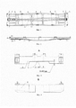
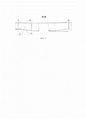
Полезная модель поясняется чертежами. На фиг. 1 представлен вид вид сверху рамы вагона-платформы; на фиг. 2 - представлен вид спереди рамы вагона-платформы; на фиг. 3 - представлен вид А, на котором изображен вид сверху балки лобовой; на фиг. 4 - представлен вид Б, на котором изображен вид справа балки лобовой; на фиг. 5 - представлено сечение В-В, на котором изображен вид сзади балки лобовой.The utility model is illustrated by drawings. FIG. 1 is a top view of a flat car frame; in fig. 2 is a front view of a flat car frame; in fig. 3 is a view A, which shows a top view of the frontal beam; in fig. 4 - view B is presented, which shows a right view of the frontal beam; in fig. 5 - section B-B is shown, which shows a rear view of the frontal beam.
Железнодорожная рама вагона-платформы для перевозки крупнотоннажных контейнеров (фиг. 1) состоит из хребтовой балки 1, соединенной с боковыми балками 2 из двутавра шкворневыми балками 3, поперечными балками 4 и лобовыми балками 5.The railway frame of the platform car for the transportation of large-tonnage containers (Fig. 1) consists of a
По верхнему листу боковых балок 2, установлены параллельно друг другу между поперечными балками 4 спаренные плиты (позицией на чертежах не показаны) для крепления оснований фитинговых упоров 6.Along the top sheet of the
Верхний лист 8, вертикальный лист 9 и нижние листы 10 лобовых балок 5 (фиг. 1), жестко соединены с верхним, нижним и вертикальным листами боковых балок 3 и хребтовой балки 1.The
Четыре одинарных плиты для крепления оснований фитинговых упоров 7 установлены в консольных частях рамы на лобовую балку 5 параллельно друг другу (фиг. 2).Four single plates for fastening the bases of the
Верхний лист 8, вертикальный лист 9 (фиг. 3-4) и нижние листы 10 (фиг. 5) лобовых балок 5 выполнены фигурными, причем угол перехода от стыка с хребтовой балкой 1 к стыку с боковыми балками 2 находится в пределах 5…90°, а также разница ширины верхнего листа 8 лобовой балки 5 в зоне примыкания к боковой балке 3 и его ширины в зоне хребтовой балки 1 находится в пределах 10-400 мм.The
Также четыре одинарных плиты (позицией на чертежах не показаны) для крепления оснований фитинговых упоров 7 установлены в консольных частях рамы на лобовую балку 5 параллельно друг другу.Also, four single plates (not shown by the position in the drawings) for fastening the bases of the
Таким образом, длина рамы платформы по осям сцепления становится меньше универсальных платформ, за счет разницы ширины верхнего листа лобовой балки в зоне примыкания к боковой балке и его ширины в зоне хребтовой балки.Thus, the length of the platform frame along the adhesion axes becomes less than the universal platforms, due to the difference in the width of the upper sheet of the frontal beam in the area of abutment to the side beam and its width in the area of the center beam.
Расположение плит для крепления оснований фитинговых упоров 6 и 7 обеспечивает возможность размещения крупнотоннажных контейнеров различного типоразмера по длине от 10 до 40 футов, в любой возможной комбинации. При этом длина рамы платформы по осям сцепления меньше по сравнению с универсальными платформами оборудованными фитинговыми упорами на 1665 мм. Что позволяет увеличить количество вагонов платформ в составе поезда не меняя его длину на 9 вагонов, а перевозимых контейнеров в таком составе на 9 по типу 1А (1АА), на 18 по типу 1С (1СС) и на 36 по типу 1D (1DD).The location of the plates for fastening the bases of the
Использование предлагаемой конструкции полезной модели позволяет сократить время погрузочных и разгрузочных работ и увеличить грузоподъемность не только отдельно взятой платформы, но поезда в целом.The use of the proposed design of the utility model makes it possible to reduce the time of loading and unloading operations and to increase the carrying capacity not only of a single platform, but of the train as a whole.
Claims (1)
Priority Applications (1)
| Application Number | Priority Date | Filing Date | Title |
|---|---|---|---|
| RU2019119800U RU192352U9 (en) | 2019-06-24 | 2019-06-24 | RAILWAY PLATFORM WAGON FRAME |
Applications Claiming Priority (1)
| Application Number | Priority Date | Filing Date | Title |
|---|---|---|---|
| RU2019119800U RU192352U9 (en) | 2019-06-24 | 2019-06-24 | RAILWAY PLATFORM WAGON FRAME |
Publications (2)
| Publication Number | Publication Date |
|---|---|
| RU192352U1 RU192352U1 (en) | 2019-09-13 |
| RU192352U9 true RU192352U9 (en) | 2021-03-30 |
Family
ID=67990266
Family Applications (1)
| Application Number | Title | Priority Date | Filing Date |
|---|---|---|---|
| RU2019119800U RU192352U9 (en) | 2019-06-24 | 2019-06-24 | RAILWAY PLATFORM WAGON FRAME |
Country Status (1)
| Country | Link |
|---|---|
| RU (1) | RU192352U9 (en) |
Families Citing this family (6)
| Publication number | Priority date | Publication date | Assignee | Title |
|---|---|---|---|---|
| RU199814U1 (en) * | 2020-05-12 | 2020-09-21 | Акционерное общество Алтайского вагоностроения (АО "Алтайвагон") | FRAME OF RAILWAY FREIGHT CAR |
| RU206807U1 (en) * | 2021-06-11 | 2021-09-28 | Акционерное общество "Рузаевский завод химического машиностроения" (АО "Рузхиммаш") | Frame of a railway freight wagon-platform |
| RU206972U1 (en) * | 2021-07-23 | 2021-10-04 | Акционерное общество "Рузаевский завод химического машиностроения" (АО "Рузхиммаш") | Rail platform frame |
| RU207422U1 (en) * | 2021-07-23 | 2021-10-28 | Акционерное общество "Рузаевский завод химического машиностроения" (АО "Рузхиммаш") | Rail platform frame |
| RU206948U1 (en) * | 2021-07-23 | 2021-10-04 | Акционерное общество "Рузаевский завод химического машиностроения" (АО "Рузхиммаш") | Rail platform frame |
| RU208029U1 (en) * | 2021-07-23 | 2021-11-30 | Акционерное общество "Рузаевский завод химического машиностроения" (АО "Рузхиммаш") | Rail platform frame |
Citations (5)
| Publication number | Priority date | Publication date | Assignee | Title |
|---|---|---|---|---|
| RU87978U1 (en) * | 2009-02-05 | 2009-10-27 | Общество с ограниченной ответственностью "Головное специализированное констркторское бюро вагоностроения" | JOINTED CAR FOR THE TRANSPORT OF LARGE-CONTAINER CONTAINERS |
| RU147022U1 (en) * | 2014-01-15 | 2014-10-27 | ОБЩЕСТВО С ОГРАНИЧЕННОЙ ОТВЕТСТВЕННОСТЬЮ "Головное специализированное конструкторское бюро вагоностроения имени Валерия Михайловича Бубнова" | RAILWAY PLATFORM FOR TRANSPORTATION OF LARGE-CONTAINER CONTAINERS |
| CN104816736A (en) * | 2015-05-27 | 2015-08-05 | 齐齐哈尔轨道交通装备有限责任公司 | Railway vehicle frame and end plate thereof |
| RU159868U1 (en) * | 2015-03-12 | 2016-02-20 | РЕЙЛ 1520 АйПи ЛТД | Gondola car |
| CN106740908A (en) * | 2016-12-20 | 2017-05-31 | 中车山东机车车辆有限公司 | A kind of low loading end Multi-purpose railway flatcar |
-
2019
- 2019-06-24 RU RU2019119800U patent/RU192352U9/en active
Patent Citations (5)
| Publication number | Priority date | Publication date | Assignee | Title |
|---|---|---|---|---|
| RU87978U1 (en) * | 2009-02-05 | 2009-10-27 | Общество с ограниченной ответственностью "Головное специализированное констркторское бюро вагоностроения" | JOINTED CAR FOR THE TRANSPORT OF LARGE-CONTAINER CONTAINERS |
| RU147022U1 (en) * | 2014-01-15 | 2014-10-27 | ОБЩЕСТВО С ОГРАНИЧЕННОЙ ОТВЕТСТВЕННОСТЬЮ "Головное специализированное конструкторское бюро вагоностроения имени Валерия Михайловича Бубнова" | RAILWAY PLATFORM FOR TRANSPORTATION OF LARGE-CONTAINER CONTAINERS |
| RU159868U1 (en) * | 2015-03-12 | 2016-02-20 | РЕЙЛ 1520 АйПи ЛТД | Gondola car |
| CN104816736A (en) * | 2015-05-27 | 2015-08-05 | 齐齐哈尔轨道交通装备有限责任公司 | Railway vehicle frame and end plate thereof |
| CN106740908A (en) * | 2016-12-20 | 2017-05-31 | 中车山东机车车辆有限公司 | A kind of low loading end Multi-purpose railway flatcar |
Also Published As
| Publication number | Publication date |
|---|---|
| RU192352U1 (en) | 2019-09-13 |
Similar Documents
| Publication | Publication Date | Title |
|---|---|---|
| RU192352U9 (en) | RAILWAY PLATFORM WAGON FRAME | |
| US4951575A (en) | Depressed center beam flat car | |
| US4917019A (en) | Railway freight car | |
| US4543887A (en) | Center beam railroad freight car | |
| RU2288121C1 (en) | Railway platform for carrying large-size containers | |
| RU2457968C2 (en) | Articulated car for haulage of large-capacity containers | |
| US4082045A (en) | Stability bracing for twist on high gondolas or hopper cars | |
| US4784067A (en) | Lightweight center beam railroad car | |
| RU162834U1 (en) | WAGON PLATFORM FOR THE CARRIAGE OF FORESTRY | |
| US4753175A (en) | Lightweight center beam railroad car | |
| RU138326U1 (en) | RAILWAY PLATFORM FOR CONTAINER AND CONTAINER TRANSPORT | |
| US4681041A (en) | Lightweight center beam railroad car | |
| CA2688382A1 (en) | Railroad well car with open truss sides | |
| RU81143U1 (en) | CONTAINER TRANSPORT PLATFORM | |
| RU202947U1 (en) | Railway platform for transporting containers | |
| RU188830U1 (en) | JOINTED TYPE WAGON HOPPER | |
| CN201506396U (en) | Self-unloading wagon carriage and self-unloading wagon with the same | |
| WO2020040664A1 (en) | Flatcar underframe | |
| RU50493U1 (en) | RAILWAY PLATFORM FOR TRANSPORTATION OF LARGE-CONTAINER CONTAINERS AND FORESTRY | |
| RU171768U1 (en) | WAGON PLATFORM FRAME | |
| RU59005U1 (en) | RAILWAY PLATFORM | |
| RU61662U1 (en) | WAGON PLATFORM WITH REMOVABLE EQUIPMENT FOR TRANSPORT OF FORESTRY AND SILVER MATERIALS | |
| RU160611U1 (en) | INDOOR WAGON HOPPER FOR CARRIAGE OF BULK CARGOES | |
| RU188838U9 (en) | Carriage frame spinal beam | |
| RU82653U1 (en) | RAILWAY PLATFORM FOR CONTAINER TRANSPORTATION |
Legal Events
| Date | Code | Title | Description |
|---|---|---|---|
| TH91 | Specification republication (utility model) |