KR20210145141A - Dynamic release tape for assembly of individual components - Google Patents
Dynamic release tape for assembly of individual components Download PDFInfo
- Publication number
- KR20210145141A KR20210145141A KR1020217029246A KR20217029246A KR20210145141A KR 20210145141 A KR20210145141 A KR 20210145141A KR 1020217029246 A KR1020217029246 A KR 1020217029246A KR 20217029246 A KR20217029246 A KR 20217029246A KR 20210145141 A KR20210145141 A KR 20210145141A
- Authority
- KR
- South Korea
- Prior art keywords
- dynamic release
- layer
- component
- release tape
- tape
- Prior art date
Links
- 238000000034 method Methods 0.000 claims abstract description 173
- 230000001678 irradiating effect Effects 0.000 claims abstract description 15
- 239000010410 layer Substances 0.000 claims description 334
- 239000012790 adhesive layer Substances 0.000 claims description 102
- 230000000712 assembly Effects 0.000 claims description 57
- 238000000429 assembly Methods 0.000 claims description 57
- 238000012546 transfer Methods 0.000 claims description 55
- 239000000758 substrate Substances 0.000 claims description 45
- 230000002745 absorbent Effects 0.000 claims description 27
- 239000002250 absorbent Substances 0.000 claims description 27
- 230000004044 response Effects 0.000 claims description 25
- 230000001070 adhesive effect Effects 0.000 claims description 20
- 239000000853 adhesive Substances 0.000 claims description 18
- 230000003287 optical effect Effects 0.000 claims description 14
- 238000010521 absorption reaction Methods 0.000 claims description 10
- 239000011521 glass Substances 0.000 claims description 5
- 229920000642 polymer Polymers 0.000 claims description 2
- 239000010453 quartz Substances 0.000 claims description 2
- VYPSYNLAJGMNEJ-UHFFFAOYSA-N silicon dioxide Inorganic materials O=[Si]=O VYPSYNLAJGMNEJ-UHFFFAOYSA-N 0.000 claims description 2
- 230000008569 process Effects 0.000 description 40
- 230000005855 radiation Effects 0.000 description 21
- 230000015572 biosynthetic process Effects 0.000 description 9
- 238000010586 diagram Methods 0.000 description 8
- 239000000463 material Substances 0.000 description 6
- 238000002679 ablation Methods 0.000 description 5
- 238000013459 approach Methods 0.000 description 4
- 238000013461 design Methods 0.000 description 3
- -1 polyethylene terephthalate Polymers 0.000 description 3
- 229920000139 polyethylene terephthalate Polymers 0.000 description 3
- 239000005020 polyethylene terephthalate Substances 0.000 description 3
- 238000012545 processing Methods 0.000 description 3
- 239000004065 semiconductor Substances 0.000 description 3
- 230000009977 dual effect Effects 0.000 description 2
- 239000000203 mixture Substances 0.000 description 2
- 230000005693 optoelectronics Effects 0.000 description 2
- 229920003229 poly(methyl methacrylate) Polymers 0.000 description 2
- 229920006254 polymer film Polymers 0.000 description 2
- 239000004926 polymethyl methacrylate Substances 0.000 description 2
- 230000008439 repair process Effects 0.000 description 2
- 239000004642 Polyimide Substances 0.000 description 1
- 239000011248 coating agent Substances 0.000 description 1
- 238000000576 coating method Methods 0.000 description 1
- 230000008094 contradictory effect Effects 0.000 description 1
- 230000032798 delamination Effects 0.000 description 1
- 230000005484 gravity Effects 0.000 description 1
- 238000004519 manufacturing process Methods 0.000 description 1
- 238000012986 modification Methods 0.000 description 1
- 230000004048 modification Effects 0.000 description 1
- 229920001721 polyimide Polymers 0.000 description 1
- 239000004800 polyvinyl chloride Substances 0.000 description 1
- 230000009467 reduction Effects 0.000 description 1
- 230000000717 retained effect Effects 0.000 description 1
- 238000007665 sagging Methods 0.000 description 1
- 238000000926 separation method Methods 0.000 description 1
- 238000004528 spin coating Methods 0.000 description 1
- 230000000638 stimulation Effects 0.000 description 1
Images


Classifications
-
- H—ELECTRICITY
- H01—ELECTRIC ELEMENTS
- H01L—SEMICONDUCTOR DEVICES NOT COVERED BY CLASS H10
- H01L21/00—Processes or apparatus adapted for the manufacture or treatment of semiconductor or solid state devices or of parts thereof
- H01L21/67—Apparatus specially adapted for handling semiconductor or electric solid state devices during manufacture or treatment thereof; Apparatus specially adapted for handling wafers during manufacture or treatment of semiconductor or electric solid state devices or components ; Apparatus not specifically provided for elsewhere
- H01L21/67005—Apparatus not specifically provided for elsewhere
- H01L21/67011—Apparatus for manufacture or treatment
- H01L21/67132—Apparatus for placing on an insulating substrate, e.g. tape
-
- B—PERFORMING OPERATIONS; TRANSPORTING
- B32—LAYERED PRODUCTS
- B32B—LAYERED PRODUCTS, i.e. PRODUCTS BUILT-UP OF STRATA OF FLAT OR NON-FLAT, e.g. CELLULAR OR HONEYCOMB, FORM
- B32B43/00—Operations specially adapted for layered products and not otherwise provided for, e.g. repairing; Apparatus therefor
- B32B43/006—Delaminating
-
- H—ELECTRICITY
- H01—ELECTRIC ELEMENTS
- H01L—SEMICONDUCTOR DEVICES NOT COVERED BY CLASS H10
- H01L21/00—Processes or apparatus adapted for the manufacture or treatment of semiconductor or solid state devices or of parts thereof
- H01L21/02—Manufacture or treatment of semiconductor devices or of parts thereof
- H01L21/04—Manufacture or treatment of semiconductor devices or of parts thereof the devices having at least one potential-jump barrier or surface barrier, e.g. PN junction, depletion layer or carrier concentration layer
- H01L21/50—Assembly of semiconductor devices using processes or apparatus not provided for in a single one of the subgroups H01L21/06 - H01L21/326, e.g. sealing of a cap to a base of a container
- H01L21/52—Mounting semiconductor bodies in containers
-
- H—ELECTRICITY
- H01—ELECTRIC ELEMENTS
- H01L—SEMICONDUCTOR DEVICES NOT COVERED BY CLASS H10
- H01L21/00—Processes or apparatus adapted for the manufacture or treatment of semiconductor or solid state devices or of parts thereof
- H01L21/67—Apparatus specially adapted for handling semiconductor or electric solid state devices during manufacture or treatment thereof; Apparatus specially adapted for handling wafers during manufacture or treatment of semiconductor or electric solid state devices or components ; Apparatus not specifically provided for elsewhere
- H01L21/67005—Apparatus not specifically provided for elsewhere
- H01L21/67011—Apparatus for manufacture or treatment
- H01L21/67092—Apparatus for mechanical treatment
-
- H—ELECTRICITY
- H01—ELECTRIC ELEMENTS
- H01L—SEMICONDUCTOR DEVICES NOT COVERED BY CLASS H10
- H01L21/00—Processes or apparatus adapted for the manufacture or treatment of semiconductor or solid state devices or of parts thereof
- H01L21/67—Apparatus specially adapted for handling semiconductor or electric solid state devices during manufacture or treatment thereof; Apparatus specially adapted for handling wafers during manufacture or treatment of semiconductor or electric solid state devices or components ; Apparatus not specifically provided for elsewhere
- H01L21/67005—Apparatus not specifically provided for elsewhere
- H01L21/67011—Apparatus for manufacture or treatment
- H01L21/67098—Apparatus for thermal treatment
- H01L21/67115—Apparatus for thermal treatment mainly by radiation
-
- H—ELECTRICITY
- H01—ELECTRIC ELEMENTS
- H01L—SEMICONDUCTOR DEVICES NOT COVERED BY CLASS H10
- H01L21/00—Processes or apparatus adapted for the manufacture or treatment of semiconductor or solid state devices or of parts thereof
- H01L21/67—Apparatus specially adapted for handling semiconductor or electric solid state devices during manufacture or treatment thereof; Apparatus specially adapted for handling wafers during manufacture or treatment of semiconductor or electric solid state devices or components ; Apparatus not specifically provided for elsewhere
- H01L21/67005—Apparatus not specifically provided for elsewhere
- H01L21/67011—Apparatus for manufacture or treatment
- H01L21/67144—Apparatus for mounting on conductive members, e.g. leadframes or conductors on insulating substrates
-
- H—ELECTRICITY
- H01—ELECTRIC ELEMENTS
- H01L—SEMICONDUCTOR DEVICES NOT COVERED BY CLASS H10
- H01L21/00—Processes or apparatus adapted for the manufacture or treatment of semiconductor or solid state devices or of parts thereof
- H01L21/67—Apparatus specially adapted for handling semiconductor or electric solid state devices during manufacture or treatment thereof; Apparatus specially adapted for handling wafers during manufacture or treatment of semiconductor or electric solid state devices or components ; Apparatus not specifically provided for elsewhere
- H01L21/683—Apparatus specially adapted for handling semiconductor or electric solid state devices during manufacture or treatment thereof; Apparatus specially adapted for handling wafers during manufacture or treatment of semiconductor or electric solid state devices or components ; Apparatus not specifically provided for elsewhere for supporting or gripping
- H01L21/6835—Apparatus specially adapted for handling semiconductor or electric solid state devices during manufacture or treatment thereof; Apparatus specially adapted for handling wafers during manufacture or treatment of semiconductor or electric solid state devices or components ; Apparatus not specifically provided for elsewhere for supporting or gripping using temporarily an auxiliary support
- H01L21/6836—Wafer tapes, e.g. grinding or dicing support tapes
-
- H—ELECTRICITY
- H01—ELECTRIC ELEMENTS
- H01L—SEMICONDUCTOR DEVICES NOT COVERED BY CLASS H10
- H01L21/00—Processes or apparatus adapted for the manufacture or treatment of semiconductor or solid state devices or of parts thereof
- H01L21/70—Manufacture or treatment of devices consisting of a plurality of solid state components formed in or on a common substrate or of parts thereof; Manufacture of integrated circuit devices or of parts thereof
- H01L21/77—Manufacture or treatment of devices consisting of a plurality of solid state components or integrated circuits formed in, or on, a common substrate
- H01L21/78—Manufacture or treatment of devices consisting of a plurality of solid state components or integrated circuits formed in, or on, a common substrate with subsequent division of the substrate into plural individual devices
-
- B—PERFORMING OPERATIONS; TRANSPORTING
- B32—LAYERED PRODUCTS
- B32B—LAYERED PRODUCTS, i.e. PRODUCTS BUILT-UP OF STRATA OF FLAT OR NON-FLAT, e.g. CELLULAR OR HONEYCOMB, FORM
- B32B2310/00—Treatment by energy or chemical effects
- B32B2310/08—Treatment by energy or chemical effects by wave energy or particle radiation
- B32B2310/0806—Treatment by energy or chemical effects by wave energy or particle radiation using electromagnetic radiation
-
- H—ELECTRICITY
- H01—ELECTRIC ELEMENTS
- H01L—SEMICONDUCTOR DEVICES NOT COVERED BY CLASS H10
- H01L21/00—Processes or apparatus adapted for the manufacture or treatment of semiconductor or solid state devices or of parts thereof
- H01L21/67—Apparatus specially adapted for handling semiconductor or electric solid state devices during manufacture or treatment thereof; Apparatus specially adapted for handling wafers during manufacture or treatment of semiconductor or electric solid state devices or components ; Apparatus not specifically provided for elsewhere
- H01L21/683—Apparatus specially adapted for handling semiconductor or electric solid state devices during manufacture or treatment thereof; Apparatus specially adapted for handling wafers during manufacture or treatment of semiconductor or electric solid state devices or components ; Apparatus not specifically provided for elsewhere for supporting or gripping
- H01L21/6838—Apparatus specially adapted for handling semiconductor or electric solid state devices during manufacture or treatment thereof; Apparatus specially adapted for handling wafers during manufacture or treatment of semiconductor or electric solid state devices or components ; Apparatus not specifically provided for elsewhere for supporting or gripping with gripping and holding devices using a vacuum; Bernoulli devices
-
- H—ELECTRICITY
- H01—ELECTRIC ELEMENTS
- H01L—SEMICONDUCTOR DEVICES NOT COVERED BY CLASS H10
- H01L2221/00—Processes or apparatus adapted for the manufacture or treatment of semiconductor or solid state devices or of parts thereof covered by H01L21/00
- H01L2221/67—Apparatus for handling semiconductor or electric solid state devices during manufacture or treatment thereof; Apparatus for handling wafers during manufacture or treatment of semiconductor or electric solid state devices or components; Apparatus not specifically provided for elsewhere
- H01L2221/683—Apparatus for handling semiconductor or electric solid state devices during manufacture or treatment thereof; Apparatus for handling wafers during manufacture or treatment of semiconductor or electric solid state devices or components; Apparatus not specifically provided for elsewhere for supporting or gripping
- H01L2221/68304—Apparatus for handling semiconductor or electric solid state devices during manufacture or treatment thereof; Apparatus for handling wafers during manufacture or treatment of semiconductor or electric solid state devices or components; Apparatus not specifically provided for elsewhere for supporting or gripping using temporarily an auxiliary support
- H01L2221/68318—Auxiliary support including means facilitating the separation of a device or wafer from the auxiliary support
- H01L2221/68322—Auxiliary support including means facilitating the selective separation of some of a plurality of devices from the auxiliary support
-
- H—ELECTRICITY
- H01—ELECTRIC ELEMENTS
- H01L—SEMICONDUCTOR DEVICES NOT COVERED BY CLASS H10
- H01L2221/00—Processes or apparatus adapted for the manufacture or treatment of semiconductor or solid state devices or of parts thereof covered by H01L21/00
- H01L2221/67—Apparatus for handling semiconductor or electric solid state devices during manufacture or treatment thereof; Apparatus for handling wafers during manufacture or treatment of semiconductor or electric solid state devices or components; Apparatus not specifically provided for elsewhere
- H01L2221/683—Apparatus for handling semiconductor or electric solid state devices during manufacture or treatment thereof; Apparatus for handling wafers during manufacture or treatment of semiconductor or electric solid state devices or components; Apparatus not specifically provided for elsewhere for supporting or gripping
- H01L2221/68304—Apparatus for handling semiconductor or electric solid state devices during manufacture or treatment thereof; Apparatus for handling wafers during manufacture or treatment of semiconductor or electric solid state devices or components; Apparatus not specifically provided for elsewhere for supporting or gripping using temporarily an auxiliary support
- H01L2221/68327—Apparatus for handling semiconductor or electric solid state devices during manufacture or treatment thereof; Apparatus for handling wafers during manufacture or treatment of semiconductor or electric solid state devices or components; Apparatus not specifically provided for elsewhere for supporting or gripping using temporarily an auxiliary support used during dicing or grinding
- H01L2221/68336—Apparatus for handling semiconductor or electric solid state devices during manufacture or treatment thereof; Apparatus for handling wafers during manufacture or treatment of semiconductor or electric solid state devices or components; Apparatus not specifically provided for elsewhere for supporting or gripping using temporarily an auxiliary support used during dicing or grinding involving stretching of the auxiliary support post dicing
-
- H—ELECTRICITY
- H01—ELECTRIC ELEMENTS
- H01L—SEMICONDUCTOR DEVICES NOT COVERED BY CLASS H10
- H01L2221/00—Processes or apparatus adapted for the manufacture or treatment of semiconductor or solid state devices or of parts thereof covered by H01L21/00
- H01L2221/67—Apparatus for handling semiconductor or electric solid state devices during manufacture or treatment thereof; Apparatus for handling wafers during manufacture or treatment of semiconductor or electric solid state devices or components; Apparatus not specifically provided for elsewhere
- H01L2221/683—Apparatus for handling semiconductor or electric solid state devices during manufacture or treatment thereof; Apparatus for handling wafers during manufacture or treatment of semiconductor or electric solid state devices or components; Apparatus not specifically provided for elsewhere for supporting or gripping
- H01L2221/68304—Apparatus for handling semiconductor or electric solid state devices during manufacture or treatment thereof; Apparatus for handling wafers during manufacture or treatment of semiconductor or electric solid state devices or components; Apparatus not specifically provided for elsewhere for supporting or gripping using temporarily an auxiliary support
- H01L2221/68363—Apparatus for handling semiconductor or electric solid state devices during manufacture or treatment thereof; Apparatus for handling wafers during manufacture or treatment of semiconductor or electric solid state devices or components; Apparatus not specifically provided for elsewhere for supporting or gripping using temporarily an auxiliary support used in a transfer process involving transfer directly from an origin substrate to a target substrate without use of an intermediate handle substrate
-
- H—ELECTRICITY
- H01—ELECTRIC ELEMENTS
- H01L—SEMICONDUCTOR DEVICES NOT COVERED BY CLASS H10
- H01L2221/00—Processes or apparatus adapted for the manufacture or treatment of semiconductor or solid state devices or of parts thereof covered by H01L21/00
- H01L2221/67—Apparatus for handling semiconductor or electric solid state devices during manufacture or treatment thereof; Apparatus for handling wafers during manufacture or treatment of semiconductor or electric solid state devices or components; Apparatus not specifically provided for elsewhere
- H01L2221/683—Apparatus for handling semiconductor or electric solid state devices during manufacture or treatment thereof; Apparatus for handling wafers during manufacture or treatment of semiconductor or electric solid state devices or components; Apparatus not specifically provided for elsewhere for supporting or gripping
- H01L2221/68304—Apparatus for handling semiconductor or electric solid state devices during manufacture or treatment thereof; Apparatus for handling wafers during manufacture or treatment of semiconductor or electric solid state devices or components; Apparatus not specifically provided for elsewhere for supporting or gripping using temporarily an auxiliary support
- H01L2221/68368—Apparatus for handling semiconductor or electric solid state devices during manufacture or treatment thereof; Apparatus for handling wafers during manufacture or treatment of semiconductor or electric solid state devices or components; Apparatus not specifically provided for elsewhere for supporting or gripping using temporarily an auxiliary support used in a transfer process involving at least two transfer steps, i.e. including an intermediate handle substrate
-
- H—ELECTRICITY
- H01—ELECTRIC ELEMENTS
- H01L—SEMICONDUCTOR DEVICES NOT COVERED BY CLASS H10
- H01L2221/00—Processes or apparatus adapted for the manufacture or treatment of semiconductor or solid state devices or of parts thereof covered by H01L21/00
- H01L2221/67—Apparatus for handling semiconductor or electric solid state devices during manufacture or treatment thereof; Apparatus for handling wafers during manufacture or treatment of semiconductor or electric solid state devices or components; Apparatus not specifically provided for elsewhere
- H01L2221/683—Apparatus for handling semiconductor or electric solid state devices during manufacture or treatment thereof; Apparatus for handling wafers during manufacture or treatment of semiconductor or electric solid state devices or components; Apparatus not specifically provided for elsewhere for supporting or gripping
- H01L2221/68304—Apparatus for handling semiconductor or electric solid state devices during manufacture or treatment thereof; Apparatus for handling wafers during manufacture or treatment of semiconductor or electric solid state devices or components; Apparatus not specifically provided for elsewhere for supporting or gripping using temporarily an auxiliary support
- H01L2221/68381—Details of chemical or physical process used for separating the auxiliary support from a device or wafer
-
- H—ELECTRICITY
- H01—ELECTRIC ELEMENTS
- H01L—SEMICONDUCTOR DEVICES NOT COVERED BY CLASS H10
- H01L33/00—Semiconductor devices with at least one potential-jump barrier or surface barrier specially adapted for light emission; Processes or apparatus specially adapted for the manufacture or treatment thereof or of parts thereof; Details thereof
- H01L33/005—Processes
- H01L33/0095—Post-treatment of devices, e.g. annealing, recrystallisation or short-circuit elimination
-
- Y—GENERAL TAGGING OF NEW TECHNOLOGICAL DEVELOPMENTS; GENERAL TAGGING OF CROSS-SECTIONAL TECHNOLOGIES SPANNING OVER SEVERAL SECTIONS OF THE IPC; TECHNICAL SUBJECTS COVERED BY FORMER USPC CROSS-REFERENCE ART COLLECTIONS [XRACs] AND DIGESTS
- Y10—TECHNICAL SUBJECTS COVERED BY FORMER USPC
- Y10T—TECHNICAL SUBJECTS COVERED BY FORMER US CLASSIFICATION
- Y10T156/00—Adhesive bonding and miscellaneous chemical manufacture
- Y10T156/11—Methods of delaminating, per se; i.e., separating at bonding face
- Y10T156/1153—Temperature change for delamination [e.g., heating during delaminating, etc.]
- Y10T156/1158—Electromagnetic radiation applied to work for delamination [e.g., microwave, uv, ir, etc.]
-
- Y—GENERAL TAGGING OF NEW TECHNOLOGICAL DEVELOPMENTS; GENERAL TAGGING OF CROSS-SECTIONAL TECHNOLOGIES SPANNING OVER SEVERAL SECTIONS OF THE IPC; TECHNICAL SUBJECTS COVERED BY FORMER USPC CROSS-REFERENCE ART COLLECTIONS [XRACs] AND DIGESTS
- Y10—TECHNICAL SUBJECTS COVERED BY FORMER USPC
- Y10T—TECHNICAL SUBJECTS COVERED BY FORMER US CLASSIFICATION
- Y10T156/00—Adhesive bonding and miscellaneous chemical manufacture
- Y10T156/19—Delaminating means
- Y10T156/1961—Severing delaminating means [e.g., chisel, etc.]
Abstract
방법은 구성 요소 이송 시스템의 지지 고정구 상에 개별 구성 요소 조립체를 위치시키는 단계를 포함하며, 개별 구성 요소 조립체는 가요성 지지 층 및 가요성 지지 층 상에 배치된 동적 해제 구조체를 포함하는 동적 해제 테이프 및 동적 해제 테이프에 부착된 개별 구성 요소를 포함한다. 방법은 동적 해제 테이프로부터 개별 구성 요소를 해제하기 위해 동적 해제 구조체에 광을 조사하는 단계를 포함한다.The method includes positioning an individual component assembly on a support fixture of a component transport system, the individual component assembly including a dynamic release tape comprising a flexible support layer and a dynamic release structure disposed on the flexible support layer and individual components affixed to the dynamic release tape. The method includes irradiating light to the dynamic release structure to release individual components from the dynamic release tape.
Description
우선권 주장claim priority
본 출원은 2019 년 5 월 6 일에 출원된 미국 특허 출원 제 62/843,904 호 및 2019 년 2 월 15 일에 출원된 미국 특허 출원 제 62/806,154 호의 우선권을 주장하며, 이들 출원의 내용이 전체적으로 여기에 참조로서 인용된다.This application claims priority to U.S. Patent Application No. 62/843,904, filed May 6, 2019, and U.S. Patent Application No. 62/806,154, filed February 15, 2019, the contents of which are hereby incorporated in their entirety. is incorporated by reference.
본 설명은 개괄적으로, 기판 상으로의 개별 구성 요소의 조립에 관한 것이다.The present description relates generally to the assembly of individual components onto a substrate.
일 양태에서, 방법은 구성 요소 이송 시스템의 지지 고정구 상에, 가요성 지지 층과 가요성 지지 층 상에 배치된 동적 해제 구조체를 포함하는 동적 해제 테이프 및 동적 해제 테이프에 접착된 개별 구성 요소를 포함하는, 개별 구성 요소 조립체를 위치시키는 단계 및 동적 해제 테이프로부터 개별 구성 요소를 해제하기 위해 동적 해제 구조체를 조사(照射)하는 단계를 포함하며, 개별 구성 요소 조립체가 지지 고정구 상에 위치된 경우 가요성 지지 층의 적어도 일부가 독립형이다.In one aspect, a method includes a dynamic release tape comprising a flexible support layer and a dynamic release structure disposed on the flexible support layer on a support fixture of a component transfer system and individual components adhered to the dynamic release tape and positioning the individual component assemblies, and irradiating the dynamic release structure to release the individual components from the dynamic release tape, wherein the individual component assemblies are flexible when positioned on the support fixture. At least a portion of the support layer is free-standing.
실시예는 다음의 특징 중 하나 이상을 가질 수 있다.Embodiments may have one or more of the following features.
지지 고정구 상에 개별 구성 요소 조립체를 위치시키는 단계는 지지 고정구의 프레임 상에 개별 구성 요소 조립체의 웨이퍼 링을 장착하는 단계를 포함한다.Positioning the individual component assemblies on the support fixture includes mounting wafer rings of the individual component assemblies on a frame of the support fixture.
방법은 개별 구성 요소를 동적 해제 테이프에 접착하는 단계를 포함한다. 개별 구성 요소를 동적 해제 테이프에 접착하는 단계는 동적 해제 구조체의 구성 요소 접착 층에 개별 구성 요소를 접착하는 단계를 포함한다. 개별 구성 요소를 동적 해제 테이프에 접착하는 단계는 개별 구성 요소를 다이싱 테이프로부터 동적 해제 테이프로 이송하는 단계를 포함한다.The method includes adhering the individual components to the dynamic release tape. Adhering the individual components to the dynamic release tape includes bonding the individual components to a component adhesive layer of the dynamic release structure. Adhering the individual components to the dynamic release tape includes transferring the individual components from the dicing tape to the dynamic release tape.
방법은 웨이퍼를 동적 해제 테이프에 접착하는 단계를 포함한다. 웨이퍼를 동적 해제 테이프에 접착하는 단계는 웨이퍼를 동적 해제 구조체의 구성 요소 접착 층에 접착하는 단계를 포함한다. 방법은 개별 구성 요소를 형성하기 위해 접착 웨이퍼를 다이싱하는 단계를 포함한다. 투명 지지 플레이트 상에 개별 구성 요소 조립체를 위치시키는 단계는 개별 구성 요소를 포함하는 동적 해제 테이프를 지지 고정구의 지지 플레이트에 부착하는 단계를 포함한다. 지지 플레이트 상에 개별 구성 요소 조립체를 위치시키는 단계는 흡입력을 인가함으로써 지지 플레이트 상에 개별 구성 요소 조립체를 유지하는 단계를 포함한다.The method includes adhering a wafer to a dynamic release tape. Adhering the wafer to the dynamic release tape includes adhering the wafer to a component adhesive layer of the dynamic release structure. The method includes dicing the adhesive wafer to form the individual components. Positioning the individual component assembly on the transparent support plate includes attaching a dynamic release tape comprising the individual component to the support plate of the support fixture. Positioning the individual component assemblies on the support plate includes maintaining the individual component assemblies on the support plate by applying a suction force.
동적 해제 구조체를 조사하는 단계는 구성 요소 이송 시스템의 광원으로부터의 광을 동적 해제 구조체에 조사하는 단계를 포함한다.Illuminating the dynamic release structure includes irradiating the dynamic release structure with light from a light source of the component transport system.
일 양태에서, 방법은 구성 요소 이송 시스템의 지지 고정구 상에, 가요성 지지 층과 가요성 지지 층 상에 배치된 동적 해제 구조체를 포함하는 동적 해제 테이프 및 동적 해제 테이프에 접착된 개별 구성 요소를 포함하는, 개별 구성 요소 조립체를 위치시키는 단계로서, 지지 고정구의 지지 플레이트 상에 직접 동적 해제 테이프의 가요성 지지 층을 위치시키는 단계를 포함하는 지지 고정구 상에 개별 구성 요소 조립체를 위치시키는 단계 및 동적 해제 테이프로부터 개별 구성 요소를 해제하기 위해 동적 해제 구조체를 조사하는 단계를 포함한다.In one aspect, a method includes a dynamic release tape comprising a flexible support layer and a dynamic release structure disposed on the flexible support layer on a support fixture of a component transfer system and individual components adhered to the dynamic release tape positioning the individual component assemblies on a support fixture comprising: placing a flexible support layer of dynamic release tape directly on a support plate of the support fixture; examining the dynamic release structure to release the individual components from the tape.
실시예는 다음의 특징 중 하나 이상을 가질 수 있다.Embodiments may have one or more of the following features.
지지 고정구 상에 개별 구성 요소 조립체를 위치시키는 단계는 지지 고정구의 프레임 상에 개별 구성 요소 조립체의 웨이퍼 링을 장착하는 단계를 포함한다.Positioning the individual component assemblies on the support fixture includes mounting wafer rings of the individual component assemblies on a frame of the support fixture.
방법은 동적 해제 테이프로부터 개별 구성 요소를 해제하기 위해 지지 플레이트를 통해 동적 해제 구조체를 조사하는 단계를 포함한다. 방법은 개별 구성 요소가 지지 플레이트와 표적 기판 사이에 위치되도록 구성 요소 이송 시스템을 배향시키는 단계를 포함한다.The method includes irradiating the dynamic release structure through the support plate to release the individual component from the dynamic release tape. The method includes orienting the component transfer system such that the individual components are positioned between the support plate and the target substrate.
지지 플레이트 상에 개별 구성 요소 조립체를 위치시키는 단계는 강성의 지지 플레이트 상에 개별 구성 요소 조립체를 위치시키는 단계를 포함한다.Positioning the individual component assemblies on the support plate includes positioning the individual component assemblies on the rigid support plate.
지지 고정구 상에 개별 구성 요소 조립체를 위치시키는 단계는 가요성 지지 층을 지지 플레이트에 직접 부착하는 단계를 포함한다.Positioning the individual component assemblies on the support fixture includes attaching the flexible support layer directly to the support plate.
지지 플레이트 상에 개별 구성 요소 조립체를 위치시키는 단계는 흡입력을 인가함으로써 지지 플레이트 상에 개별 구성 요소 조립체를 유지하는 단계를 포함한다.Positioning the individual component assemblies on the support plate includes maintaining the individual component assemblies on the support plate by applying a suction force.
지지 플레이트 상에 개별 구성 요소 조립체를 위치시키는 단계는 지지 플레이트에 걸쳐 동적 해제 테이프를 신장시키는 단계를 포함한다.Positioning the individual component assemblies on the support plate includes stretching the dynamic release tape across the support plate.
방법은 개별 구성 요소를 동적 해제 테이프에 접착하는 단계를 포함한다. 개별 구성 요소를 동적 해제 테이프에 접착하는 단계는 동적 해제 구조체의 구성 요소 접착 층에 개별 구성 요소를 접착하는 단계를 포함한다. 개별 구성 요소를 동적 해제 테이프에 접착하는 단계는 개별 구성 요소를 다이싱 테이프로부터 동적 해제 테이프로 이송하는 단계를 포함한다.The method includes adhering the individual components to the dynamic release tape. Adhering the individual components to the dynamic release tape includes bonding the individual components to a component adhesive layer of the dynamic release structure. Adhering the individual components to the dynamic release tape includes transferring the individual components from the dicing tape to the dynamic release tape.
방법은 웨이퍼를 동적 해제 테이프에 접착하는 단계를 포함한다. 웨이퍼를 동적 해제 테이프에 접착하는 단계는 웨이퍼를 동적 해제 구조체의 구성 요소 접착 층에 접착하는 단계를 포함한다. 방법은 개별 구성 요소를 형성하기 위해 접착 웨이퍼를 다이싱하는 단계를 포함한다. 투명 지지 플레이트 상에 개별 구성 요소 조립체를 위치시키는 단계는 개별 구성 요소를 포함하는 동적 해제 테이프를 지지 고정구의 지지 플레이트에 부착하는 단계를 포함한다. 지지 플레이트 상에 개별 구성 요소 조립체를 위치시키는 단계는 흡입력을 인가함으로써 지지 플레이트 상에 개별 구성 요소 조립체를 유지하는 단계를 포함한다.The method includes adhering a wafer to a dynamic release tape. Adhering the wafer to the dynamic release tape includes adhering the wafer to a component adhesive layer of the dynamic release structure. The method includes dicing the adhesive wafer to form the individual components. Positioning the individual component assembly on the transparent support plate includes attaching a dynamic release tape comprising the individual component to the support plate of the support fixture. Positioning the individual component assemblies on the support plate includes maintaining the individual component assemblies on the support plate by applying a suction force.
동적 해제 구조체를 조사하는 단계는 구성 요소 이송 시스템의 광원으로부터의 광을 동적 해제 구조체에 조사하는 단계를 포함한다.Illuminating the dynamic release structure includes irradiating the dynamic release structure with light from a light source of the component transport system.
일 양태에서, 개별 구성 요소 이송 시스템은 광원, 지지 프레임 및 지지 프레임 상에 위치되며 광원에 의해 방출된 광에 대해 투과성인 지지 플레이트를 포함하는 개별 구성 요소 지지 고정구, 및 광원과 지지 프레임 사이에 배치된 광학 요소를 포함한다.In one aspect, a discrete component transport system includes a discrete component support fixture comprising a light source, a support frame, and a support plate positioned on the support frame and transparent to light emitted by the light source, and disposed between the light source and the support frame. included optical elements.
실시예는 다음의 특징 중 하나 이상을 가질 수 있다.Embodiments may have one or more of the following features.
시스템은 지지 플레이트에 대해 개별 구성 요소 조립체의 가요성 지지 층을 유지하기 위해 개별 구성 요소 지지 고정구의 공기 유동 채널에 흡입력을 인가하도록 구성된 흡입력 공급원을 포함한다.The system includes a suction force source configured to apply a suction force to an air flow channel of the individual component support fixture to maintain the flexible support layer of the individual component assembly relative to the support plate.
시스템은 가요성 지지 층과 가요성 지지 층 상에 배치된 동적 해제 구조체를 포함하는 동적 해제 테이프; 및 동적 해제 테이프에 접착된 개별 구성 요소를 포함하는 개별 구성 요소 조립체를 포함하며, 동적 해제 테이프의 가요성 지지 층이 지지 플레이트 상에 직접 위치되며 개별 구성 요소 지지 고정구의 공기 유동 채널을 통한 흡입력에 의해 제자리에 유지된다. 공기 유동 채널이 지지 프레임의 두께를 통해 형성된다. 공기 유동 채널이 지지 플레이트의 두께를 통해 형성된다.The system includes a dynamic release tape comprising a flexible support layer and a dynamic release structure disposed on the flexible support layer; and a discrete component assembly comprising discrete components adhered to the dynamic release tape, wherein the flexible support layer of the dynamic release tape is positioned directly on the support plate and resists suction force through the air flow channels of the discrete component support fixture. held in place by An air flow channel is formed through the thickness of the support frame. An air flow channel is formed through the thickness of the support plate.
지지 플레이트의 상부 표면이 개별 구성 요소 지지 고정구 상에 유지된 동적 해제 테이프에 인장 응력을 도입하기에 충분한 양만큼 지지 프레임의 상부 표면으로부터 오정렬된다.The upper surface of the support plate is misaligned from the upper surface of the support frame by an amount sufficient to introduce a tensile stress to the dynamic release tape held on the individual component support fixtures.
지지 플레이트가 유리 플레이트를 포함한다.The support plate comprises a glass plate.
지지 플레이트가 유리 플레이트를 포함한다.The support plate comprises a glass plate.
지지 플레이트가 강성이다.The support plate is rigid.
광학 요소가 렌즈를 포함한다.The optical element includes a lens.
일 양태에서, 개별 구성 요소 이송 시스템은 광원; 개별 구성 요소 지지 고정구; 개별 구성 요소 지지 고정구 상에 배치된 개별 구성 요소 조립체로서, 가요성 지지 층과 가요성 지지 층 상에 배치된 동적 해제 구조체를 포함하는 동적 해제 테이프; 및 동적 해제 테이프에 접착된 개별 구성 요소를 포함하며, 개별 구성 요소 조립체가 개별 구성 요소 지지 고정구 상에 배치된 경우 동적 해제 테이프가 독립형 것인 개별 구성 요소 조립체; 및 광원과 개별 구성 요소 조립체 사이에 배치된 광학 요소를 포함한다.In one aspect, the individual component transport system comprises a light source; individual component support fixtures; A discrete component assembly disposed on a discrete component support fixture, comprising: a dynamic release tape comprising a flexible support layer and a dynamic release structure disposed on the flexible support layer; and an individual component assembly adhered to the dynamic release tape, wherein the dynamic release tape is free-standing when the individual component assembly is disposed on the individual component support fixture; and an optical element disposed between the light source and the individual component assembly.
실시예는 다음의 특징 중 하나 이상을 포함할 수 있다.Embodiments may include one or more of the following features.
개별 구성 요소 조립체가 개별 구성 요소 지지 고정구 상에 배치된 웨이퍼 링을 포함한다.The individual component assembly includes a wafer ring disposed on the individual component support fixture.
일 양태에서, 방법은 개별 구성 요소를 형성하기 위해 다이싱 테이프에 접착된 웨이퍼를 다이싱하는 단계; 가요성 지지 층 및 가요성 지지 층 상에 배치된 동적 해제 구조체를 포함하는 개별 구성 요소 조립체를 형성하기 위해 다이싱 테이프로부터 동적 해제 테이프로 개별 구성 요소를 이송하는 단계; 및 구성 요소 이송 시스템의 지지 플레이트 상에 직접 개별 구성 요소 조립체의 가요성 지지 층을 위치시키는 단계를 포함한다.In one aspect, a method includes dicing a wafer adhered to a dicing tape to form individual components; transferring the individual components from the dicing tape to the dynamic release tape to form an individual component assembly comprising a flexible support layer and a dynamic release structure disposed on the flexible support layer; and positioning the flexible support layer of the individual component assembly directly on the support plate of the component transport system.
실시예는 다음의 특징 중 하나 이상을 포함할 수 있다.Embodiments may include one or more of the following features.
동적 해제 테이프로 개별 구성 요소를 이송하는 단계는 동적 해제 구조체의 구성 요소 접착 층에 개별 구성 요소를 접착하는 단계를 포함한다.Transferring the individual components to the dynamic release tape includes adhering the individual components to the component adhesive layer of the dynamic release structure.
동적 해제 테이프의 동적 해제 구조체가 다수의 층을 포함한다. 동적 해제 구조체가 활성 층 구조체 및 구성 요소 접착 층을 포함하며, 동적 해제 테이프에 웨이퍼를 접착하는 단계는 구성 요소 접착 층에 웨이퍼를 접착하는 단계를 포함한다.The dynamic release structure of the dynamic release tape includes multiple layers. The dynamic release structure includes an active layer structure and a component adhesive layer, wherein adhering the wafer to the dynamic release tape includes adhering the wafer to the component adhesive layer.
지지 플레이트 상에 직접 가요성 지지 층을 위치시키는 단계는 가요성 지지 층을 지지 플레이트에 직접 부착하는 단계를 포함한다.Placing the flexible support layer directly on the support plate includes attaching the flexible support layer directly to the support plate.
지지 플레이트 상에 직접 가요성 지지 층을 위치시키는 단계는 흡입력을 인가함으로써 지지 플레이트 상에 개별 구성 요소 조립체를 유지하는 단계를 포함한다.Placing the flexible support layer directly on the support plate includes holding the individual component assemblies on the support plate by applying a suction force.
지지 플레이트 상에 직접 가요성 지지 층을 위치시키는 단계는 지지 플레이트에 걸쳐 동적 해제 테이프를 신장시키는 단계를 포함한다.Placing the flexible support layer directly on the support plate includes stretching the dynamic release tape across the support plate.
방법은 동적 해제 테이프로부터 개별 구성 요소를 해제하기 위해 지지 플레이트를 통해 개별 조립체의 동적 해제 구조체에 광을 조사하는 단계를 포함한다.The method includes irradiating light to a dynamic release structure of the individual assembly through a support plate to release the individual component from the dynamic release tape.
일 양태에서, 방법은 개별 구성 요소를 형성하기 위해 다이싱 테이프에 접착된 웨이퍼를 다이싱하는 단계; 가요성 지지 층 및 가요성 지지 층 상에 배치된 동적 해제 구조체를 포함하는 개별 구성 요소 조립체를 형성하기 위해 다이싱 테이프로부터 동적 해제 테이프로 개별 구성 요소를 이송하는 단계; 및 동적 해제 테이프의 적어도 일부가 독립형이도록 구성 요소 이송 시스템에 개별 구성 요소 조립체를 위치시키는 단계를 포함한다.In one aspect, a method includes dicing a wafer adhered to a dicing tape to form individual components; transferring the individual components from the dicing tape to the dynamic release tape to form an individual component assembly comprising a flexible support layer and a dynamic release structure disposed on the flexible support layer; and positioning the individual component assemblies in the component transport system such that at least a portion of the dynamic release tape is free-standing.
실시예는 다음의 특징 중 하나 이상을 포함할 수 있다.Embodiments may include one or more of the following features.
방법은 동적 해제 테이프로부터 개별 구성 요소를 해제하기 위해 독립형 동적 해제 테이프를 조사하는 단계를 포함한다.The method includes examining the standalone dynamic release tape to release individual components from the dynamic release tape.
동적 해제 테이프의 동적 해제 구조체가 다수의 층을 포함한다. 동적 해제 구조체가 활성 층 구조체 및 구성 요소 접착 층을 포함하며, 동적 해제 테이프에 웨이퍼를 접착하는 단계는 구성 요소 접착 층에 웨이퍼를 접착하는 단계를 포함한다.The dynamic release structure of the dynamic release tape includes multiple layers. The dynamic release structure includes an active layer structure and a component adhesive layer, wherein adhering the wafer to the dynamic release tape includes adhering the wafer to the component adhesive layer.
일 양태에서, 방법은 독립형 가요성 지지 층 및 가요성 지지 층 상에 배치된 동적 해제 구조체를 포함하는 동적 해제 테이프에 웨이퍼를 접착하는 단계; 및 동적 해제 테이프에 접착된 개별 구성 요소를 형성하기 위해 접착 웨이퍼를 다이싱하는 단계를 포함한다.In one aspect, a method includes: adhering a wafer to a dynamic release tape comprising a free-standing flexible support layer and a dynamic release structure disposed on the flexible support layer; and dicing the adhesive wafer to form individual components adhered to the dynamic release tape.
실시예는 다음의 특징 중 하나 이상을 포함할 수 있다.Embodiments may include one or more of the following features.
웨이퍼를 동적 해제 테이프에 접착하는 단계는 웨이퍼를 동적 해제 구조체의 구성 요소 접착 층에 접착하는 단계를 포함한다.Adhering the wafer to the dynamic release tape includes adhering the wafer to a component adhesive layer of the dynamic release structure.
동적 해제 테이프의 동적 해제 구조체가 다수의 층을 포함한다. 동적 해제 구조체가 활성 층 구조체 및 구성 요소 접착 층을 포함하며, 동적 해제 테이프에 웨이퍼를 접착하는 단계는 구성 요소 접착 층에 웨이퍼를 접착하는 단계를 포함한다.The dynamic release structure of the dynamic release tape includes multiple layers. The dynamic release structure includes an active layer structure and a component adhesive layer, wherein adhering the wafer to the dynamic release tape includes adhering the wafer to the component adhesive layer.
일 양태에서, 방법은 가요성 지지 층 및 가요성 지지 층 상에 배치된 동적 해제 구조체를 포함하는 동적 해제 테이프에 웨이퍼를 부착하는 단계; 개별 구성 요소 조립체를 포함하는, 동적 해제 테이프에 접착된 개별 구성 요소를 형성하기 위해 접착 웨이퍼를 다이싱하는 단계; 및 개별 구성 요소 조립체의 가요성 지지 층을 구성 요소 이송 시스템의 지지 플레이트 상에 직접 위치시키는 단계를 포함한다.In one aspect, a method includes attaching a wafer to a dynamic release tape comprising a flexible support layer and a dynamic release structure disposed on the flexible support layer; dicing the adhesive wafer to form individual components adhered to the dynamic release tape, including individual component assemblies; and placing the flexible support layer of the individual component assembly directly on the support plate of the component transport system.
실시예는 다음의 특징 중 하나 이상을 포함할 수 있다.Embodiments may include one or more of the following features.
가요성 지지 층을 지지 플레이트 상에 직접 위치시키는 단계는 동적 해제 테이프의 가요성 지지 층을 지지 플레이트에 직접 부착하는 단계를 포함한다.Placing the flexible support layer directly on the support plate includes attaching the flexible support layer of the dynamic release tape directly to the support plate.
가요성 지지 층을 지지 플레이트 상에 직접 위치시키는 단계는 흡입력을 인가함으로써 지지 플레이트 상에 개별 구성 요소 조립체를 유지하는 단계를 포함한다.Placing the flexible support layer directly on the support plate includes holding the individual component assemblies on the support plate by applying a suction force.
가요성 지지 층을 지지 플레이트 상에 위치시키는 단계는 지지 플레이트에 걸쳐 동적 해제 테이프를 신장시키는 단계를 포함한다.Positioning the flexible support layer on the support plate includes stretching the dynamic release tape across the support plate.
방법은 동적 해제 테이프로부터 개별 구성 요소를 해제하기 위해 지지 플레이트를 통해 개별 조립체의 동적 해제 구조체에 광을 조사하는 단계를 포함한다.The method includes irradiating light to a dynamic release structure of the individual assembly through a support plate to release the individual component from the dynamic release tape.
동적 해제 테이프의 동적 해제 구조체가 다수의 층을 포함한다. 동적 해제 구조체가 활성 층 구조체 및 구성 요소 접착 층을 포함하며, 동적 해제 테이프에 웨이퍼를 접착하는 단계는 구성 요소 접착 층에 웨이퍼를 접착하는 단계를 포함한다.The dynamic release structure of the dynamic release tape includes multiple layers. The dynamic release structure includes an active layer structure and a component adhesive layer, wherein adhering the wafer to the dynamic release tape includes adhering the wafer to the component adhesive layer.
일 양태에서, 방법은 가요성 지지 층 및 가요성 지지 층 상에 배치된 동적 해제 구조체를 포함하는 동적 해제 테이프에 웨이퍼를 접착하는 단계; 개별 구성 요소 조립체를 포함하는, 동적 해제 테이프에 접착된 개별 구성 요소를 형성하기 위해 접착 웨이퍼를 다이싱하는 단계; 및 동적 해제 테이프의 적어도 일부가 독립형이도록 구성 요소 이송 시스템에 개별 구성 요소 조립체를 위치시키는 단계를 포함한다.In one aspect, a method includes adhering a wafer to a dynamic release tape comprising a flexible support layer and a dynamic release structure disposed on the flexible support layer; dicing the adhesive wafer to form individual components adhered to the dynamic release tape, including individual component assemblies; and positioning the individual component assemblies in the component transport system such that at least a portion of the dynamic release tape is free-standing.
실시예는 다음의 특징 중 하나 이상을 포함할 수 있다.Embodiments may include one or more of the following features.
방법은 동적 해제 테이프로부터 개별 구성 요소를 해제하기 위해 독립형 동적 해제 테이프를 조사하는 단계를 포함한다.The method includes examining the standalone dynamic release tape to release individual components from the dynamic release tape.
동적 해제 테이프의 동적 해제 구조체가 다수의 층을 포함한다. 동적 해제 구조체가 활성 층 구조체 및 구성 요소 접착 층을 포함하며, 동적 해제 테이프에 웨이퍼를 접착하는 단계는 구성 요소 접착 층에 웨이퍼를 접착하는 단계를 포함한다.The dynamic release structure of the dynamic release tape includes multiple layers. The dynamic release structure includes an active layer structure and a component adhesive layer, wherein adhering the wafer to the dynamic release tape includes adhering the wafer to the component adhesive layer.
일 양태에서, 장치는 가요성 지지 층; 및 가요성 지지 층 상에 배치된 동적 해제 구조체를 포함하는 동적 해제 테이프를 포함한다.In one aspect, a device comprises a flexible support layer; and a dynamic release tape comprising a dynamic release structure disposed on the flexible support layer.
실시예는 다음의 특징 중 하나 이상을 포함할 수 있다.Embodiments may include one or more of the following features.
동적 해제 테이프가 동적 해제 테이프로부터의 개별 구성 요소의 레이저 이송을 가능하게 하기에 충분히 강성이다.The dynamic release tape is rigid enough to enable laser transfer of individual components from the dynamic release tape.
동적 해제 테이프가 동적 해제 테이프로부터의 개별 구성 요소의 레이저 이송 동안 실질적으로 평면형 구성을 유지하기에 충분히 강성이다. 가요성 지지 층이 중합체를 포함한다. 동적 해제 구조체가 다수의 층을 포함한다. 동적 해제 구조체가 가요성 지지 층 상에 배치되며 가요성 지지 층에 접착되도록 구성되며 광 조사에 응답하여 가스를 생성하도록 구성된 흡수 및 접착 층; 및 흡수 및 접착 층 상에 배치된 활성 층을 포함한다. 활성 층이 흡수 및 접착 층에 의한 가스의 생성에 기계적으로 응답하도록 구성된 블리스터 형성 층을 포함한다. 동적 해제 구조체가 가요성 지지 층 상에 배치되며 가요성 지지 층에 접착되도록 구성된 접착 층; 및 접착 층 상에 배치된 활성 층 구조체를 포함한다. 활성 층 구조체가 광 조사에 응답하여 가스를 생성하도록 구성되며 가스 생성에 기계적으로 응답하도록 구성된 흡수 및 블리스터 형성 층을 포함한다. 활성 층 구조체가 접착 층 상에 배치되며 광 조사에 응답하여 가스를 생성하도록 구성된 흡수 층 및 흡수 층에 의한 가스 생성에 기계적으로 응답하도록 구성된 블리스터 형성 층을 포함한다. 동적 해제 구조체의 층 중 하나가 구성 요소 접착 층을 포함한다. 구성 요소 접착 층의 접착력은 자극 인가에 응답성을 갖는다.The dynamic release tape is sufficiently rigid to maintain a substantially planar configuration during laser transfer of individual components from the dynamic release tape. The flexible support layer comprises a polymer. The dynamic release structure includes multiple layers. an absorbing and adhesive layer having a dynamic release structure disposed on the flexible support layer and configured to adhere to the flexible support layer and configured to generate a gas in response to irradiation with light; and an active layer disposed on the absorbent and adhesive layer. The active layer includes a blister-forming layer configured to mechanically respond to generation of gas by the absorbent and adhesive layer. an adhesive layer having the dynamic release structure disposed on the flexible support layer and configured to adhere to the flexible support layer; and an active layer structure disposed on the adhesive layer. The active layer structure is configured to generate a gas in response to irradiation with light and includes an absorptive and blister forming layer configured to mechanically respond to generation of the gas. An active layer structure is disposed on the adhesive layer and includes an absorbing layer configured to generate a gas in response to irradiation with light and a blister forming layer configured to mechanically respond to gas generation by the absorbing layer. One of the layers of the dynamic release structure includes a component adhesion layer. The adhesive force of the component adhesive layer is responsive to the application of the stimulus.
테이프가 신장 가능하다.The tape is stretchable.
가요성 지지 층이 자외선 투과성이다.The flexible support layer is UV transmissive.
장치는 동적 해제 구조에 접착된 개별 구성 요소를 포함한다. 개별 구성 요소가 발광 다이오드(LED)를 포함한다.The device includes individual components bonded to a dynamic release structure. Individual components include light emitting diodes (LEDs).
일 양태에서, 방법은 동적 해제 테이프를 형성하기 위해 가요성 지지 층 상에 동적 해제 구조체를 형성하는 단계를 포함한다.In one aspect, a method includes forming a dynamic release structure on a flexible support layer to form a dynamic release tape.
실시예는 다음의 특징 중 하나 이상을 포함할 수 있다.Embodiments may include one or more of the following features.
동적 해제 구조체를 형성하는 단계는 가요성 지지 층 상에 다수의 층을 형성하는 단계를 포함한다. 동적 해제 구조체를 형성하는 단계는 가요성 지지 층 상에, 가요성 지지 층에 접착되도록 구성되며 광 조사에 응답하여 가스를 생성하도록 구성된 흡수 및 접착 층을 형성하는 단계; 및 흡수 및 접착 층 상에 활성 층을 형성하는 단계를 포함한다. 활성 층이 흡수 및 접착 층에 의한 가스 생성에 기계적으로 응답하도록 구성된 블리스터 형성 층을 포함한다. 동적 해제 구조체를 형성하는 단계는 가요성 지지 층 상에 가요성 지지 층에 접착되도록 구성된 접착 층을 형성하는 단계; 및 접착 층 상에 활성 층 구조체를 형성하는 단계를 포함한다. 활성 층 구조체가 광 조사에 응답하여 가스를 생성하도록 구성되며 가스 생성에 기계적으로 응답하도록 구성된 흡수 및 블리스터 형성 층을 포함한다. 활성 층 구조체를 형성하는 단계는 접착 층 상에, 광 조사에 응답하여 가스를 생성하도록 구성된 흡수 층을 형성하는 단계 및 흡수 층에 의한 가스 생성에 기계적으로 응답하도록 구성된 블리스터 형성 층을 형성하는 단계를 포함한다.Forming the dynamic release structure includes forming a plurality of layers on the flexible support layer. Forming the dynamic release structure includes forming, on the flexible support layer, an absorbing and adhesive layer configured to adhere to the flexible support layer and configured to generate a gas in response to irradiation with light; and forming an active layer on the absorbent and adhesive layer. The active layer includes a blister-forming layer configured to mechanically respond to gas generation by the absorbent and adhesive layer. Forming the dynamic release structure may include forming on the flexible support layer an adhesive layer configured to adhere to the flexible support layer; and forming an active layer structure on the adhesive layer. The active layer structure is configured to generate a gas in response to irradiation with light and includes an absorptive and blister forming layer configured to mechanically respond to generation of the gas. Forming the active layer structure includes forming, on the adhesive layer, an absorbing layer configured to generate a gas in response to irradiation with light and forming a blister forming layer configured to mechanically respond to generation of a gas by the absorbing layer. includes
일 양태에서, 동적 해제 장치는 가요성 지지 층; 및 가요성 지지 층 상에 배치된 동적 해제 구조체로서, 가요성 지지 층 상에 배치되며 가요성 지지 층에 접착되도록 구성된 접착 층 및 접착 층 상에 배치된 활성 층 구조체를 포함하는 동적 해제 지지 구조체를 포함한다.In one aspect, a dynamic release device includes a flexible support layer; and a dynamic release support structure disposed on the flexible support layer, the dynamic release support structure comprising an adhesive layer disposed on the flexible support layer and configured to adhere to the flexible support layer and an active layer structure disposed on the adhesive layer. include
실시예는 다음의 특징 중 하나 이상을 가질 수 있다.Embodiments may have one or more of the following features.
활성 층 구조체가 광 조사에 응답하여 가스를 생성하도록 구성되며 가스 생성에 기계적으로 응답하도록 구성된 흡수 및 블리스터 형성 층을 포함한다.The active layer structure is configured to generate a gas in response to irradiation with light and includes an absorptive and blister forming layer configured to mechanically respond to generation of the gas.
활성 층 구조체가 접착 층 상에 배치되며 광 조사에 응답하여 가스를 생성하도록 구성된 흡수 층 및 흡수 층에 의한 가스 생성에 기계적으로 응답하도록 구성된 블리스터 형성 층을 포함한다.An active layer structure is disposed on the adhesive layer and includes an absorbing layer configured to generate a gas in response to irradiation with light and a blister forming layer configured to mechanically respond to gas generation by the absorbing layer.
동적 해제 구조체가 구성 요소 접착 층을 포함한다.The dynamic release structure includes a component adhesive layer.
일 양태에서, 방법은 가요성 지지 층과 가요성 지지 층 상에 배치된 동적 해제 구조체를 포함하는 동적 해제 테이프 및 동적 해제 테이프에 접착된 개별 구성 요소를 포함하는 개별 구성 요소 조립체를 구성 요소 이송 시스템의 지지 고정구 상에 위치시키는 단계를 포함한다. 방법은 동적 해제 테이프로부터 개별 구성 요소를 해제하기 위해 동적 해제 구조체를 조사하는 단계를 포함한다.In one aspect, a method provides a dynamic release tape comprising a flexible support layer and a dynamic release structure disposed on the flexible support layer and a discrete component assembly comprising individual components adhered to the dynamic release tape into a component transport system. and placing it on a support fixture of The method includes examining the dynamic release structure to release individual components from the dynamic release tape.
일 양태에서, 개별 구성 요소 이송 시스템은 광원, 지지 프레임 및 지지 프레임 상에 위치되며 광원에 의해 방출된 광에 대해 투과성인 지지 플레이트를 포함하는 개별 구성 요소 지지 고정구, 및 광원과 지지 프레임 사이에 배치된 광학 요소를 포함한다.In one aspect, a discrete component transport system includes a discrete component support fixture comprising a light source, a support frame, and a support plate positioned on the support frame and transparent to light emitted by the light source, and disposed between the light source and the support frame. included optical elements.
일 양태에서, 개별 구성 요소 이송 시스템은 광원; 개별 구성 요소 지지 고정구; 및 개별 구성 요소 지지 고정구 상에 배치된 개별 구성 요소 조립체를 포함한다. 개별 구성 요소 조립체는 가요성 지지 층과 가요성 지지 층 상에 배치된 동적 해제 구조체를 포함하는 동적 해제 테이프 및 동적 해제 테이프에 접착된 개별 구성 요소를 포함한다. 개별 구성 요소 이송 시스템은 광원과 개별 구성 요소 조립체 사이에 배치된 광학 요소를 포함한다.In one aspect, the individual component transport system comprises a light source; individual component support fixtures; and a discrete component assembly disposed on the discrete component support fixture. The discrete component assembly includes a dynamic release tape including a flexible support layer and a dynamic release structure disposed on the flexible support layer and a discrete component adhered to the dynamic release tape. The discrete component transport system includes an optical element disposed between the light source and the discrete component assembly.
일 양태에서, 방법은 개별 구성 요소를 형성하기 위해 다이싱 테이프에 접착된 웨이퍼를 다이싱하는 단계; 및 가요성 지지 층 및 가요성 지지 층 상에 배치된 동적 해제 구조체를 포함하는 개별 구성 요소 조립체를 형성하기 위해 다이싱 테이프로부터 동적 해제 테이프로 개별 구성 요소를 이송하는 단계를 포함한다. In one aspect, a method includes dicing a wafer adhered to a dicing tape to form individual components; and transferring the individual components from the dicing tape to the dynamic release tape to form an individual component assembly comprising a flexible support layer and a dynamic release structure disposed on the flexible support layer.
일 양태에서, 방법은 가요성 지지 층 및 가요성 지지 층 상에 배치된 동적 해제 구조체를 포함하는 동적 해제 테이프에 웨이퍼를 접착하는 단계; 및 동적 해제 테이프에 접착된 개별 구성 요소를 형성하기 위해 접착 웨이퍼를 다이싱하는 단계를 포함한다.In one aspect, a method includes adhering a wafer to a dynamic release tape comprising a flexible support layer and a dynamic release structure disposed on the flexible support layer; and dicing the adhesive wafer to form individual components adhered to the dynamic release tape.
일 양태에서, 장치는 가요성 지지 층 및 가요성 지지 층 상에 배치된 동적 해제 구조체를 포함하는 동적 해제 테이프를 포함한다.In one aspect, an apparatus includes a dynamic release tape comprising a flexible support layer and a dynamic release structure disposed on the flexible support layer.
일 양태에서, 방법은 동적 해제 테이프를 형성하기 위해 가요성 지지 층 상에 동적 해제 구조체를 형성하는 단계를 포함한다. 일 양태에서, 동적 해제 장치는 지지 층; 및 지지 층 상에 배치된 동적 해제 구조체로서, 지지 층 상에 배치되며 지지 층에 접착되도록 구성된 접착 층 및 접착 층 상에 배치된 활성 층 구조체를 포함하는 동적 해제 구조체를 포함한다.In one aspect, a method includes forming a dynamic release structure on a flexible support layer to form a dynamic release tape. In one aspect, a dynamic release device includes a support layer; and a dynamic release structure disposed on the support layer, the dynamic release structure comprising an adhesive layer disposed on the support layer and configured to adhere to the support layer and an active layer structure disposed on the adhesion layer.
도 1a 및 도 1b는 레이저 보조 이송 공정의 선도이다.
도 2a 및 도 2b는 지지 고정구를 갖는 동적 해제 테이프의 선도이다.
도 3은 지지 고정구를 갖는 동적 해제 테이프의 선도이다.
도 4 및 도 5는 개별 구성 요소의 레이저 보조 이송용 시스템의 선도이다.
도 6 및 도 7은 공정도이다.
도 8a 내지 도 8c는 지지 플레이트 상에 장착된 다층 동적 해제 테이프의 선도이다.
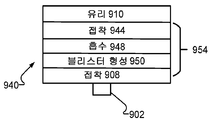
도 9a 내지 도 9c는 다층 동적 해제 구조체의 선도이다.
도 10은 지지 고정구를 갖는 동적 해제 테이프의 선도이다.1A and 1B are diagrams of a laser assisted transfer process.
2A and 2B are diagrams of a dynamic release tape having a support fixture;
3 is a diagram of a dynamic release tape with a support fixture;
4 and 5 are diagrams of a system for laser assisted transport of individual components.
6 and 7 are process diagrams.
8A-8C are diagrams of a multilayer dynamic release tape mounted on a support plate.
9A-9C are diagrams of a multi-layer dynamic release structure.
10 is a diagram of a dynamic release tape with a support fixture;
여기서, 구성 요소 이송 시스템의 지지 플레이트 상에 위치된 박형의 가요성 동적 해제 테이프로부터의 개별 구성 요소의 레이저 보조 이송에 대한 접근 방식이 설명된다. 동적 해제 테이프는 백킹(backing)과 같은 지지 층 상에 배치된 다층 동적 해제 구조체를 포함한다. 동적 해제 구조체의 각각의 층은 특별히 접착, 광학 특성 또는 기계적 특성과 같은 동적 해제 구조체의 하나 이상의 기능을 목표로 하도록 설계될 수 있다. 또한, 캐리어 기판 상에 배치되는 동적 해제 테이프로부터의 개별 구성 요소의 레이저 보조 이송이 설명된다.Here, an approach to laser assisted transport of individual components from a thin flexible dynamic release tape positioned on the support plate of a component transport system is described. The dynamic release tape includes a multilayer dynamic release structure disposed on a support layer, such as a backing. Each layer of the dynamic release structure may be specifically designed to target one or more functions of the dynamic release structure, such as adhesion, optical properties, or mechanical properties. Also described is laser assisted transfer of individual components from a dynamic release tape disposed on a carrier substrate.
도 1a 및 도 1b에는 강성 또는 가요성 기판 상으로의 개별 구성 요소(102)의 높은 처리량의, 저비용 무접촉 조립을 위한 레이저 보조 이송 공정이 도시되어 있다. 개별 구성 요소라는 용어는 일반적으로, 예를 들어, 제품 또는 전자 장치의 일부가 될 임의의 유닛, 예를 들어, 전자, 전기 기계, 광전지, 광전자 또는 광전자 구성 요소, 모듈 또는 시스템, 예를 들어, 반도체 재료로 이루어진 부분에 형성된 회로를 갖는 임의의 반도체 재료를 의미한다. 일부 예에서, 개별 구성 요소가 발광 다이오드(LED)일 수 있다. 개별 구성 요소는 최대 두께가 50 ㎛ 이하, 40 ㎛ 이하, 30 ㎛ 이하, 25 ㎛ 이하, 20 ㎛ 이하, 10 ㎛ 이하, 또는 5 ㎛ 이하인 초박형일 수 있다. 개별 구성 요소가 최대 길이 또는 폭 치수가 일 측면당 300 ㎛, 일 측면당 100 ㎛, 일 측면당 50 ㎛, 일 측면당 20 ㎛ 또는 일 측면당 5 ㎛ 이하인 초소형일 수 있다. 개별 구성 요소가 초박형 및 초소형일 수 있다.1A and 1B illustrate a laser assisted transfer process for high-throughput, low-cost, contactless assembly of
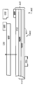
도 1a 및 도 1b는 개별 구성 요소(102)의 레이저 보조 이송을 위한 구성 요소 이송 시스템의 지지 고정구(100)의 일부를 보여준다. 지지 고정구(100)는 레이저 보조 이송 공정을 위해 가요성 개별 구성 요소 조립체(108)를 제 위치에 유지한다. 지지 고정구(아래에서 더 상세히 설명됨)는 프레임(도시하지 않음; 아래에서 더 상세히 설명됨) 상에 장착된 강성 지지 플레이트(106)를 포함할 수 있다. 프레임은 강성 지지 플레이트(106)에 안정성을 제공한다. 일부 예에서, 프레임이, 예를 들어, 정렬 목적으로 조작될 수 있다. 개별 구성 요소 조립체(108)는 아래에서 더 상세히 설명되는 바와 같이 흡입력, 인장 응력에 의해 또는 다른 방식으로 지지 플레이트(106)에 부착될 수 있다. 지지 플레이트(106) 상의 개별 구성 요소 조립체(108)의 위치 설정은 비영구적이므로, 예를 들어, 지지 플레이트(106)를 손상시키지 않고 레이저 보조 이송 공정이 완료된 후 개별 구성 요소 조립체(108)가 지지 플레이트(106)로부터 제거될 수 있다. 지지 플레이트(106) 상의 개별 구성 요소 조립체(108)의 비영구적인 부착에 의해 지지 플레이트(106)가 다수의 개별 구성 요소 조립체(108)를 포함하는 다수의 이송 공정에 이용 가능하다.1A and 1B show a portion of a
개별 구성 요소 조립체(108)는 웨이퍼 링(도시하지 않음) 상에 장착된 동적 해제 테이프(110)를 포함하며, 개별 구성 요소(102)가 동적 해제 테이프(110)에 부착된다. 여기서는 단일 개별 구성 요소(102)만을 보여주지만, 다수의 개별 구성 요소(102)가 또한 동적 해제 테이프(110)에 부착되어 구성 요소 이송 시스템에 의해 이송될 수 있다. 동적 해제 테이프(예를 들어, 테이프(110))는 가요성 지지 층(112) 및 가요성 지지 층(112) 상에 배치된 동적 해제 구조체(114)를 포함하는 테이프이다. 테이프는 하나 이상의 층으로 구성된 박형의 가요성 재료이다. 가요성 지지 층(112)이 지지 고정구(100)의 지지 플레이트(106)와 접촉하며, 개별 구성 요소(102)가 동적 해제 구조체(114)에 부착된다. 동적 해제 구조체(114)가 아래에서 더 상세히 논의되는 바와 같이 2 개, 3 개, 4 개 또는 4 개를 초과하는 층을 구비한 구조체와 같은 다층 구조체일 수 있다.The
또한 도 1b를 참조하면, 레이저 보조 이송 공정에서, 지지 플레이트(106)의 배면에 광, 예를 들어, 레이저 빔과 같은 방사선(116)이 조사된다. 지지 플레이트(106) 및 동적 해제 테이프(110)의 가요성 지지 층(112)이 모두 방사선(116)의 파장(예를 들어, 레이저 에너지)에 대해 투과성이다. 주어진 파장에 대해 투과성인 요소는 주어진 파장의 적어도 일부 방사선이 통과하는 요소이다. 방사선(116)은 지지 플레이트(106) 및 동적 해제 테이프(110)의 가요성 지지 층(112)을 통과하여 동적 해제 구조체(114)의 영역에 입사되어, 방사선(116)이 입사되는 영역(이를 조사 영역이라고 함)에서 동적 해제 구조체(114)의 일부 두께의 절제가 야기된다. 절제는 팽창되는 제한된 가스를 생성하여, 동적 해제 구조체(114)에 응력을 생성한다. 응력에 의해 동적 해제 구조체(114)의 재료 중 적어도 일부가 변형되어, 블리스터(118)를 형성한다. 블리스터(118)는 개별 구성 요소(102) 상에 기계적 힘을 가한다. 블리스터(118)에 의해 가해진 기계적 힘이 개별 구성 요소(102)와 동적 해제 구조체(114) 사이의 접착을 극복하기에 충분하면, 블리스터(118)에 의해 가해지는 기계적 힘(중력과 함께)이 표적 기판(130)으로의 이송을 위해 개별 구성 요소를 지지 플레이트(106)로부터 멀어지도록(예를 들어, 하향 방향으로) 밀어낸다.Also referring to FIG. 1B , in the laser-assisted transfer process, light, for example,
표적 기판(130)이 개별 구성 요소(102)에 매우 근접하여, 예를 들어, 약 5 ㎛ 내지 약 300 ㎛의 거리에 위치될 수 있다. 테이프 기반 개별 구성 요소 조립체(108)를 지지하기 위해 강성 지지 플레이트(106)를 사용하는 것은, 예를 들어, 테이프(110)의 처짐 또는 다른 구조적 변동을 방지함으로써 개별 구성 요소 조립체(108)의 개별 구성 요소(102)와 표적 기판(130) 사이의 일관성 있는 분리를 유지하는 것을 돕는다. 일부 예에서, 지지 플레이트(106)가 고도의 표면 평탄도를 갖출 수 있다. 예를 들어, 지지 플레이트(106)가 고정밀도로 기계 가공될 수 있다.The
일부 레이저 보조 이송 공정에서는, 개별 구성 요소가 동적 해제 구조체에 의해 강성의 투명한 캐리어 기판에 부착된다. 개별 구성 요소가 부착된 캐리어 기판이 개별 구성 요소의 레이저 보조 이송을 위한 구성 요소 이송 시스템에 제공된다. 강성의 투명한 지지 플레이트가 구성 요소 이송 시스템 자체에 통합된 여기에 설명된 구성 요소 이송 시스템에 의해, 개별 구성 요소가 강성의 캐리어 기판이 아닌 테이프로부터 이송될 수 있어, 단부 간 개별 구성 요소 이송 공정의 비용(예를 들어, 재료, 제조, 운송 등의 비용)이 감소될 수 있다. 예를 들어, 강성의 캐리어 기판이 동적 해제 테이프보다 훨씬 더 비쌀 수 있다. 또한, 동적 해제 테이프가 일회용이므로, 강성의 캐리어 기판을 보수할 필요가 없으며 이와 관련한 비용이 들지 않는다.In some laser assisted transfer processes, individual components are attached to a rigid transparent carrier substrate by a dynamic release structure. A carrier substrate to which the individual components are attached is provided in a component transport system for laser assisted transport of the individual components. By means of the component transfer system described herein, in which a rigid transparent support plate is incorporated into the component transfer system itself, individual components can be transferred from tape rather than from a rigid carrier substrate, thereby reducing end-to-end individual component transfer processes. Costs (eg, costs of materials, manufacturing, transportation, etc.) may be reduced. For example, a rigid carrier substrate may be much more expensive than a dynamic release tape. In addition, since the dynamic release tape is disposable, there is no need to repair the rigid carrier substrate and there are no costs associated with it.
일부 예에서, 개별 구성 요소 이송 공정에 사용되는 동적 해제 테이프는 독립형 테이프이다. 독립형 테이프는 강성 기판에 부착되지 않은 테이프이다. 일부 예에서, 독립형 테이프가 개별 구성 요소 이송 공정의 하나 이상의 단계에서 강성 기판 상에 위치될 수는 있지만 부착되지는 않을 수 있다. 예를 들어, 개별 구성 요소를 테이프에 부착하는 동안, 구성 요소 이송 시스템으로의 도입 동안, 또는 개별 구성 요소의 레이저 보조 이송 동안 독립형 테이프가 강성 기판에 위치될 수 있다.In some instances, the dynamic release tape used in the individual component transfer process is a free-standing tape. A free-standing tape is a tape that is not attached to a rigid substrate. In some examples, free-standing tapes may be positioned but not attached to the rigid substrate in one or more steps of the individual component transfer process. For example, a free-standing tape may be positioned on a rigid substrate during attachment of an individual component to the tape, during introduction into a component transfer system, or during laser assisted transfer of an individual component.
일부 예에서, 개별 구성 요소 이송 공정에 사용되는 동적 해제 테이프가 독립형 테이프가 아니라, 대신에 테이프에 개별 구성 요소를 부착하는 동안, 구성 요소 이송 시스템으로의 도입 동안 및 개별 구성 요소의 레이저 보조 이송 동안 강성 기판에 부착된다.In some instances, the dynamic release tape used in the individual component transfer process is not a standalone tape, but instead attaches individual components to the tape, during introduction into a component transfer system, and during laser assisted transfer of individual components. It is attached to a rigid substrate.
레이저 보조 이송 공정에 대한 추가 설명은 미국 특허 공개 공보 제 US 2014/0238592 호에서 찾을 수 있으며, 그 내용이 전체적으로 참조로서 여기에 인용된다.Further description of the laser assisted transfer process can be found in US Patent Publication No. US 2014/0238592, the contents of which are incorporated herein by reference in their entirety.
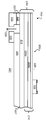
도 2a 및 도 2b는 레이저 보조 이송 공정을 위해 개별 구성 요소 조립체(208)를 위치시키기 위한 지지 플레이트(206)를 포함하는 예시적인 지지 고정구(200)의 절개도를 보여준다. 지지 플레이트(206)는 레이저 이송 공정에 사용되는 방사선, 예를 들어, 자외선(UV) 광의 파장에 투과성을 갖는 강성 플레이트이다. 예를 들어, 지지 플레이트(206)가 유리 플레이트, 석영 플레이트, 또는 다른 재료의 플레이트일 수 있다. 지지 플레이트(206)가 지지 고정구의 프레임(220) 상에 장착된다. 도 2a 및 도 2b에 도시된 바와 같은 일부 예에서, 프레임(220)은 방사선이 지지 플레이트(206)에 도달할 수 있도록 하는 개구(221)를 구비한다. 일부 예에서는, 프레임(220)이 개구를 가지지 않을 수 있으며, 방사선이 프레임(220)을 통해 투과되도록 방사선의 파장에 투과성일 수 있다.2A and 2B show cutaway views of an
개별 구성 요소 조립체(208)는 웨이퍼 링(222) 상에 장착된 독립형 동적 해제 테이프(210)를 포함하며, 개별 구성 요소(102)가 동적 해제 테이프(210)에 부착된다. 예를 들어, 동적 해제 테이프(210)가 웨이퍼 링(222) 상에서 신장될 수 있다. 도 2a 및 도 2b의 예에서, 동적 해제 테이프(210)는 가요성 지지 층(212)을 포함하며, 가요성 지지 층(212) 상에 다층 동적 해제 구조체(214)가 배치된다. 예시적인 다층 동적 해제 구조체(214)는 접착, 방사선 흡수 및 블리스터 형성 기능을 갖는 다수의 하위 층(224a, 224b) 및 개별 구성 요소(102)에 부착되는 구성 요소 접착 층(226)을 포함한다. 다층 동적 해제 구조체(214)가 아래에서 더 상세히 논의된다.The
구체적으로 도 2b를 참조하면, 구성 요소 이송 시스템의 지지 플레이트(206) 상에 개별 구성 요소 조립체(208)를 위치시키기 위해, 웨이퍼 링(222)이 프레임(220)과 접촉되며, 동적 해제 테이프(210)의 가요성 지지 층(212)의 배면이 지지 플레이트(206)와 접촉된다. 이와 같이 위치되면, 웨이퍼 링(222)의 상부 표면(223)이 지지 플레이트(206)의 상부 표면(207)과 실질적으로 수평을 이루어(예를 들어, 정렬되어), 동적 해제 테이프(210)가 그 전체 측방향 범위에 걸쳐 실질적으로 평평하다.Referring specifically to FIG. 2B , to position the
지지 플레이트(206)에 대해 동적 해제 테이프(210)를 유지하기 위해, 예를 들어, 구성 요소 이송 시스템의 흡입력에 의해 공기 유동 채널(228)을 통해 흡입력이 인가된다. 예를 들어, 공기 유동 채널(228)이 구성 요소 이송 시스템(도시된 바와 같음)의 프레임(220)의 두께를 통해 또는 지지 플레이트(206)의 두께를 통해 또는 둘 모두를 통해 획정될 수 있다. 흡입력을 인가하면, 예를 들어, 동적 해제 구조체(214)가 실질적으로 평평하도록 지지 플레이트(206)에 대해 동적 해제 테이프(210)가 단단히 당겨진다.To hold the
도 10을 참조하면, 일부 예에서는, 지지 고정구(150)가 프레임(170)을 포함하지만, 지지 플레이트(예를 들어, 도 2a 및 도 2b에 도시된 바와 같은 지지 플레이트(206))는 포함하지 않는다. 개별 구성 요소 조립체(208)의 웨이퍼 링(222)이 지지 고정구(150)의 프레임(170) 상에 장착되며, 그렇지 않으면 동적 해제 테이프(210)가 레이저 보조 이송 공정을 위해 독립 상태로 유지된다. 동적 해제 테이프(210)가 레이저 보조 이송 공정 기간 동안 실질적으로 평면형의 구성을 유지하기에 충분히 강성인 것과 같이 충분한 강성을 갖추면, 독립형 동적 해제 테이프(210)로부터의 직접적인 레이저 보조 이송이 수행될 수 있다. 예를 들어, 개별 구성 요소 조립체(208)가 프레임(170) 상에 장착된 경우 테이프(210)의 평면에 수직인 방향(z)에서의 동적 해제 테이프(210)의 최대 편차가 임계량보다 더 작도록, 예를 들어, 20 ㎛ 미만, 10 ㎛ 미만, 또는 5 ㎛ 미만이도록 동적 해제 테이프(210)가 충분히 강성일 수 있다. Referring to FIG. 10 , in some examples,
도 3은 레이저 보조 이송 공정을 위해 개별 구성 요소 조립체(208)를 위치시키기 위한 지지 플레이트(306)를 포함하는 예시적인 지지 고정구(300)의 절개도를 보여준다. 지지 플레이트(306)는 레이저 이송 공정에 사용되는 방사선, 예를 들어, UV 광의 파장에 투과성을 갖는 강성 플레이트이다. 지지 플레이트(306)가 지지 고정구(300)의 프레임(320) 상에 장착된다. 프레임(320)은 방사선이 지지 플레이트(306)에 도달할 수 있도록 하는 개구(321)를 구비한다. 일부 예에서, 방사선이 프레임(320)을 통해 투과되도록 프레임(320)이 방사선의 파장에 투과성일 수 있다.3 shows a cutaway view of an
도 3의 예에서, 개별 구성 요소 조립체(208)가 지지 고정구(300) 상에 위치된 경우, 웨이퍼 링(222)의 상부 표면(223)이 지지 플레이트(306)의 상부 표면(307)보다 아래 높이에 있다(예를 들어, 오정렬된다). 예를 들어, 개별 구성 요소 조립체(208)가 지지 플레이트 상에 위치된 경우 지지 플레이트(306)와 웨이퍼 링(222)이 여전히 오정렬이 상태에 있도록 지지 고정구(300)의 프레임(320)이 지지 플레이트(306)의 상부 표면으로부터 일정량 오정렬될 수 있다. 이러한 오정렬로 인해 지지 플레이트(306)에 대해 동적 해제 테이프(210)를 유지하는 인장 응력이 동적 해제 테이프(210)에 가해져, 예를 들어, 동적 해제 구조체(214)가 실질적으로 평평하다. 인장 응력의 양 및 이에 따라 동적 해제 테이프(210)를 지지 플레이트(306)에 대해 유지하는 힘은 웨이퍼 링(222)의 상부 표면(223)과 지지 플레이트(306)의 상부 표면(307) 사이의 높이차를 변경함으로써 제어될 수 있다. In the example of FIG. 3 , when the
일부 예에서, 예를 들어, 자기력, 정전기, 기계적 고정을 포함한 접근법이나 다른 접근법을 사용함으로써, 구성 요소 이송 시스템의 지지 플레이트 상에 동적 해제 테이프(210)를 위치시키기 위해 다른 접근법이 사용될 수 있다.In some examples, other approaches may be used to position the
도 4는 구성 요소 이송 시스템(450)의 일 예를 보여준다. 구성 요소 이송 시스템(450)은 프레임(420) 상에 장착된 지지 플레이트(406)를 구비한 지지 고정구(400)를 포함한다. 지지 고정구(400)는 개별 구성 요소 조립체(408)가 지지 플레이트(406) 상에 유지되도록 위치된다. 개별 구성 요소 조립체(408)는 개별 구성 요소(102)가 부착된 동적 해제 테이프(410)를 포함하며, 동적 해제 테이프(410)가 웨이퍼 링(422) 상에 장착되며, 예를 들어, 웨이퍼 링(422) 상에서 신장된다. 예를 들어, 웨이퍼 링(422)이 프레임(420) 상에 위치되며, 신장된 동적 해제 테이프(410)가 지지 플레이트(406)에 대해 유지된다. 개별 구성 요소 조립체(408)에 광원(452), 예를 들어, 레이저로부터의 방사선(예를 들어, UV 광과 같은 광)이 조사될 수 있다. 광원(452)으로부터의 광은 광원(452)과 지지 플레이트(406)의 사이에 배치된 렌즈와 같은 광학 요소(454)에 의해 조작되며, 예를 들어, 집속될 수 있다. 프레임(420)이 광원(452)으로부터의 방사선이 지지 플레이트(406)에 도달할 수 있도록 하는 개구(421)를 구비한다. 기판 홀더(432)에 의해 개별 구성 요소가 레이저 보조 이송 공정에 의해 이송되는 표적 기판(430)이 유지된다.4 shows an example of a
일부 예에서, 지지 고정구(400)가 흡입력 인가에 의해 지지 플레이트(406)에 대해 별개의 구성 요소 조립체를 유지하도록 구성되는 경우, 구성 요소 이송 시스템(450)이 지지 플레이트(406) 또는 프레임(420)의 하나 이상의 공기 유동 채널(도시하지 않음)에 유체 유동적으로 연결(예를 들어, 튜브(도시하지 않음)에 의해)되는 흡입력 공급원(434)을 포함할 수 있다.In some examples, when the support fixture 400 is configured to hold a separate component assembly relative to the
도 5는 광원(552) 및 광학 요소(554)를 구비한 구성 요소 이송 시스템(550)의 일 예를 보여준다. 구성 요소 이송 시스템(550)은 프레임(520)을 포함하는 지지 고정구(500)를 포함한다. 프레임(520)에는 지지 플레이트가 장착되어 있지 않다. 개별 구성 요소 조립체(508)가 프레임(520) 상에 유지되며, 개별 구성 요소 조립체(508)가 웨이퍼 링(522)에 장착된 동적 해제 테이프(510)를 포함한다. 이 구성에서, 개별 구성 요소 조립체(508)의 웨이퍼 링(522)이 프레임(520) 상에 위치되며, 동적 해제 테이프(510)는 레이저 보조 이송 공정 동안 독립형 테이프(강성 기판 또는 지지 플레이트에 의해 지지되지 않는 테이프를 의미함)이다. 개별 구성 요소(102)가 기판 홀더(532)에 의해 유지된 표적 기판(530) 상으로 이송된다.5 shows an example of a
일부 예에서, 구성 요소 이송 시스템(450, 550)이 다수의 개별 구성 요소의 병렬 이송을 위해 구성될 수 있거나, 전체 내용이 참조로서 여기에 인용된 2018 년 4 월 25 일에 출원된 WO2018/231344에 더 상세히 설명된 바와 같이 단일 구성 요소 이송 모드 및 다수의 구성 요소 이송 모드를 갖도록 구성될 수 있다.In some examples,
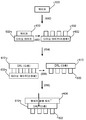
도 6을 참조하면, 일부 예에서, 개별 구성 요소(602)가 다이싱 공정 후에 동적 해제 테이프(610)로 이송될 수 있다. 하나 이상의 전자 구성 요소(예를 들어, 집적 회로)를 포함하는 웨이퍼(630)가 다이싱 테이프(632)에 부착되며(650), 예를 들어, 웨이퍼 다이싱을 위한 표준 웨이퍼 처리 기술을 사용하여 개별 구성 요소(602)를 형성하도록 다이싱된다(652). 예를 들어, 다이싱 테이프(632)가 웨이퍼 링 상에 장착될 수 있다. 일부 예에서, 다이싱 공정이 다이싱 테이프를 측방향으로 신장시켜, 예를 들어, 다이싱 테이프(632)를 웨이퍼 링 상으로 확장함으로써 개별 구성 요소(602)를 분리하는 단계를 포함할 수 있다.Referring to FIG. 6 , in some examples,
개별 구성 요소(602)가 동적 해제 테이프(610) 상으로 이송되며(654), 다이싱 테이프(632)가 제거되어(656), 개별 구성 요소(602)가 동적 해제 테이프(610)에 부착된 상태로 남게 된다. 예를 들어, 개별 구성 요소(602)가 동적 해제 테이프(610)의 구성 요소 접착 층에 부착될 수 있다(아래에서 논의됨). 개별 구성 요소(602)가 부착된 동적 해제 테이프(610)가 표적 기판 상으로의 개별 구성 요소(602)의 레이저 보조 이송을 위한 구성 요소 이송 시스템의 투명한 강성의 지지 플레이트(606)에 부착된다(658). 예를 들어, 동적 해제 테이프(610)의 가요성 지지 층이, 예를 들어, 흡입력, 인장 응력에 의해 또는 다른 방식으로 지지 플레이트에 부착된다.The
도 7을 참조하면, 일부 예에서, 개별 구성 요소(702)가 동적 해제 테이프(710) 상에서 직접 다이싱될 수 있다. 하나 이상의 반도체 다이(예를 들어, 집적 회로)를 포함하는 웨이퍼(730)가 동적 해제 테이프(710), 예를 들어, 동적 해제 테이프(710)의 구성 요소 접착 층에 접착된다(750). 접착된 웨이퍼(730)가, 예를 들어, 웨이퍼 다이싱을 위한 표준 웨이퍼 처리 기술을 사용하여 개별 구성 요소(702)를 형성하도록 다이싱된다(752). 예를 들어, 동적 해제 테이프(710)가 웨이퍼 링 상에 장착될 수 있다. 일부 예에서, 동적 해제 층 테이프(710)가 신장 가능하며, 다이싱 공정이, 예를 들어, 웨이퍼 링 상의 동적 해제 테이프를 확장함으로써 개별 구성 요소(702)를 분리하기 위해 동적 해제 층 테이프(710)를 측방향으로 신장시키는 단계를 포함할 수 있다.Referring to FIG. 7 , in some examples,
개별 구성 요소(702)가 부착된 동적 해제 층 테이프(710)가 표적 기판 상으로의 개별 구성 요소(702)의 레이저 보조 이송을 위한 구성 요소 이송 시스템의 투명한 강성의 지지 플레이트(706)에 부착된다(754). 예를 들어, 동적 해제 테이프(710)의 가요성 지지 층이, 예를 들어, 흡입력, 인장 응력에 의해 또는 다른 방식으로 지지 플레이트에 부착된다.A dynamic
도 7의 공정에는, 다이싱 테이프로부터 동적 해제 층 테이프로 다이싱된 개별 구성 요소(702)를 이송하는 단계가 포함되지 않아, 도 7의 공정이 능률적이고 효율적으로 된다.The process of FIG. 7 does not include transferring the diced
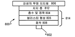
도 8a 내지 도 8c를 참조하면, 동적 해제 층 테이프(800, 820, 840)는 가요성 지지 층(812) 및 가요성 지지 층(812) 상에 배치된 다층 동적 해제 구조체(814, 834, 854)를 각각 구비한 다층 테이프일 수 있다. 개별 구성 요소(802)가 각각의 다층 동적 해제 구조체(814, 834, 854)의 일부를 형성하는 구성 요소 접착 층(808)에 의해 동적 해제 구조체(814, 834, 854)에 접착될 수 있다. 다층 동적 해제 구조체(814, 834, 854)는 다양한 조성 및 기능을 갖는 다양한 개수의 층으로 형성될 수 있다. 도 8a 내지 도 8c에 도시된 바와 같이, 동적 해제 층 테이프(800, 820, 840)는 레이저 보조 이송 공정에 사용되는 방사선에 투과성인 구성 요소 이송 시스템의 지지 플레이트(806)와 같은 강성 지지체 상에 위치될 수 있다. 일부 예에서, 동적 해제 층 테이프(800, 820, 840)가 웨이퍼 링에 부착되거나, 달리 사용되는 바와 같이 다른 환경에서 사용될 수 있다.8A-8C , the dynamic
가요성 지지 층(812)은 레이저 보조 이송 공정에 사용되는 방사선에 투과성인, 예를 들어, UV 광에 투과성인 박형의 가요성 필름이다. 예를 들어, 가요성 지지 층(812)이 폴리비닐클로라이드(PVC), 폴리에틸렌 테레프탈레이트(PET) 또는 폴리(메틸 메타크릴레이트)(PMMA)와 같은 중합체 필름일 수 있다. 가요성 지지 층(812)은 동적 해제 층 테이프(800, 820, 840)가 테이프를 파괴하지 않고 조작, 예를 들어, 말리거나, 구부리거나, 신장될 수 있도록 하기에 충분히 박형이며 가요성이다. 가요성 지지 층(812)이 존재함으로써 동적 해제 층 테이프(800, 820, 840)가, 예를 들어, 강성 기판에 부착되지 않고 취급될 수 있는 충분한 기계적 무결성을 갖는 독립형 테이프가 될 수 있다.The flexible support layer 812 is a thin, flexible film that is transparent to radiation, eg, transparent to UV light, used in the laser assisted transfer process. For example, flexible support layer 812 can be a polymer film such as polyvinylchloride (PVC), polyethylene terephthalate (PET), or poly(methyl methacrylate) (PMMA). The flexible support layer 812 is sufficiently thin and flexible to allow the dynamic
구체적으로 도 8a를 참조하면, 일부 예에서, 동적 해제 층 테이프(800)의 동적 해제 구조체(814)가 가요성 지지 층(812) 상에 배치된 흡수 및 접착 층(804) 및 흡수 및 접착 층(804) 상에 배치된 블리스터 형성 층(도 8a에 도시됨)과 같은 활성 층(805)을 구비한 3층 구조체일 수 있다. 구성 요소 접착 층(808)이 활성 층(805) 상에 배치된다.Referring specifically to FIG. 8A , in some examples, an absorbent and adhesive layer 804 and an absorbent and adhesive layer disposed on a flexible support layer 812 , the
흡수 및 접착 층(804)은 이중 기능(가요성 지지 층(812)에 대한 활성 층(805)의 결합 및 레이저 보조 이송 공정 동안 조사로 인한 에너지의 흡수)을 갖는다. 예를 들어, 흡수 및 접착 층(804)은, 예를 들어, 방사선이 테이프(800)에 접착된 개별 구성 요소에 도달하여 개별 구성 요소를 손상시킬 가능성을 방지하기 위해 흡수 및 접착 층(804)에 입사되는 에너지의 적어도 90%, 적어도 95%, 적어도 98%, 또는 적어도 99%를 흡수한다.The absorbing and adhesive layer 804 has a dual function (bonding of the active layer 805 to the flexible support layer 812 and absorption of energy due to irradiation during the laser assisted transfer process). For example, the absorbent and adhesive layer 804 may be applied to, for example, the absorbent and adhesive layer 804 to prevent radiation from reaching and damaging the individual components adhered to the tape 800 , for example. absorbs at least 90%, at least 95%, at least 98%, or at least 99% of the energy incident on it.
흡수 및 접착 층(804)에 의한 에너지 흡수에 의해 층이 절제되어 가스가 생성된다. 인접한 활성 층(805)이 생성 가스에 기계적으로 응답한다. 예를 들어, 도 8a에 도시된 바와 같이, 활성 층(805)이 가스 생성에 응답하여 블리스터가 형성되는(예를 들어, 도 1b에 도시된 바와 같음) 블리스터 형성 층일 수 있다.Absorption and energy absorption by the adhesive layer 804 ablates the layer to produce a gas. The adjacent active layer 805 is mechanically responsive to the product gas. For example, as shown in FIG. 8A , the active layer 805 may be a blister-forming layer that blisters in response to gas generation (eg, as shown in FIG. 1B ).
도 8b를 참조하면, 일부 예에서, 동적 해제 층 테이프(820)의 동적 해제 구조체(834)가 가요성 지지 층(812) 상에 배치된 접착 층(824) 및 접착 층(824) 상에 배치된 흡수 및 블리스터 형성 층(도 8b에 도시된 바와 같음)과 같은 활성 층(826)을 갖는 3층 구조체일 수 있다. 구성 요소 접착 층(808)이 활성 층(826) 상에 배치된다.Referring to FIG. 8B , in some examples, the
접착 층(824)은 활성 층(826)을 가요성 지지 층(812)에 결합하기에 충분한 접착력을 나타낸다. 도 8b의 예에서, 활성 층(826)은 흡수 및 블리스터 형성 층이다. 활성 층(826)은 레이저 보조 이송 공정 동안 조사로 인한 에너지를 흡수하여, 활성 층(826)에서의 블리스터 형성과 같은 기계적 응답을 유도하는 가스를 생성한다. 예를 들어, 활성 층(826)은 입사 에너지의 적어도 90%, 적어도 95%, 적어도 98%, 또는 적어도 99%를 흡수할 수 있다.Adhesive layer 824 exhibits sufficient adhesion to bond active layer 826 to flexible support layer 812 . In the example of FIG. 8B , the active layer 826 is an absorbent and blister-forming layer. The active layer 826 absorbs energy due to irradiation during the laser assisted transport process, creating a gas that induces a mechanical response such as blister formation in the active layer 826 . For example, the active layer 826 can absorb at least 90%, at least 95%, at least 98%, or at least 99% of the incident energy.
도 8c를 참조하면, 일부 예에서, 동적 해제 층 테이프(840)의 동적 해제 구조체(854)가 가요성 지지 층(812) 상에 배치된 접착 층(844) 및 접착 층(844) 상에 배치된 활성 층 구조체(846)를 갖는 4층 구조체일 수 있다. 구성 요소 접착 층(808)이 활성 층 구조체(846) 상에 배치된다.Referring to FIG. 8C , in some examples, the
접착 층(844)은 활성 층 구조체(846)를 가요성 지지 층(812)에 결합하기에 충분한 접착력을 나타낸다. 활성 층 구조체(846)는 2 개의 층, 즉, 흡수 층(848) 및 블리스터 형성 층(850)을 포함한다. 흡수 층(848)은 레이저 보조 이송 공정 동안 조사로 인한 에너지를 흡수하여, 가스를 생성한다. 예를 들어, 흡수 층(848)은 입사 에너지의 적어도 90%, 적어도 95%, 적어도 98%, 또는 적어도 99%를 흡수할 수 있다. 가스 생성은 블리스터 형성 층(850)에서 블리스터 형성과 같은 기계적 응답을 유도한다.Adhesive layer 844 exhibits sufficient adhesion to bond
동적 해제 구조체(예를 들어, 동적 해제 구조체(814, 834, 854))는 다수의 기능, 예를 들어, 가요성 지지 층에 대한 접착, 층 간의 내부 접착, 입사 방사선의 흡수 및 기계적 응답(예를 들어, 블리스터 형성)을 갖는다. 동적 해제 구조체(814, 834, 854)의 다층 특성에 의해 각각의 층이 이러한 기능 중 하나 이상을 달성하도록 특별히 설계되는 것이 허용될 수 있다.Dynamic release structures (eg,
도 8a의 예에서, 흡수 및 접착 층(804)은 지지 층(812)에 접착되어 입사 방사선을 흡수하며, 활성 층(805)에서의 블리스터 형성을 야기하기에 충분한 양의 가스를 생성하도록 설계될 수 있다. 일부 예에서는, 흡수 및 접착 층(804)이 내부 접착을 촉진하도록, 예를 들어, 인접 위치의 개별 구성 요소, 예를 들어, 이송을 위한 개별 구성 요소에 영향을 미칠 가능성이 있는 큰 직경의 블리스터를 초래할 수 있는 블리스터의 박리를 적어도 부분적으로 회피하기 위해 충분한 접착력으로 활성 층(805)에 접착되도록 설계될 수 있다. 흡수 및 접착 층(804)의 설계에서는, 층의 광학 및 접착 특성이 설계의 초점이 될 수 있는 반면, 강도 또는 탄성율과 같은 층의 기계적 특성은 설계에 있어 부차적인 요인일 수 있다. 반대로, 활성 층(805)의 두께 및 조성이, 예를 들어, 원하는 블리스터 형성 반응을 달성하기 위해 기계적 특성에 중점을 두고 설계될 수 있는 반면, 층의 광학 및 접착 특성은 부차적일 수 있다. 일부 예에서는, 활성 층(805)이 목표 크기의 블리스터 형성을 허용하며 파열되지 않는 기계적 특성을 갖추며, 흡수 및 접착 층(804)에 의해 생성된 임의의 가스가 동적 해제 구조체(814)로부터 탈출하는 것을 방지하도록 설계될 수 있다. 예를 들어, 목표 블리스터 크기는 높이-대-직경의 비율이 약 1일 수 있으며 기부 직경이 조사 빔(예를 들어, 레이저 빔)의 직경의 약 3배보다 크지 않을 수 있다. 특정 예에서, 활성 층(805)은 약 2 ㎛ 내지 약 5 ㎛의 두께를 갖는 중합체 필름, 예를 들어, PET 또는 폴리이미드로 이루어진 필름일 수 있다.In the example of FIG. 8A , the absorbing and adhesive layer 804 is designed to adhere to the support layer 812 , to absorb incident radiation, and to generate a sufficient amount of gas to cause blister formation in the active layer 805 . can be In some instances, the absorbent and adhesive layer 804 promotes internal adhesion, eg, a large diameter blister that is likely to affect individual components in adjacent locations, eg, individual components for transport. It can be designed to adhere to the active layer 805 with sufficient adhesion to at least partially avoid delamination of the blisters that can cause blistering. In the design of the absorbent and adhesive layer 804, the optical and adhesive properties of the layer may be the focus of the design, while the mechanical properties of the layer, such as strength or modulus of elasticity, may be secondary factors in the design. Conversely, the thickness and composition of the active layer 805 may be designed with emphasis on mechanical properties to achieve a desired blister-forming response, for example, while the optical and adhesive properties of the layer may be secondary. In some examples, the active layer 805 has mechanical properties that do not rupture and allow blister formation of a target size, and any gas generated by the absorbent and adhesive layer 804 escapes from the
또한, 도 8a의 동적 해제 구조체(814)에서, 활성 층(805) 자체는 에너지를 흡수하지 않으므로 부분적으로 절제되지 않는다. 오히려, 인접한 흡수 및 접착 층(804)에서 절제가 발생한다. 활성 층(805)에서 절제가 발생하지 않기 때문에, 활성 층(805)의 두께는 블리스터 위치로 이송된 레이저 에너지의 양에 의해 영향을 받지 않으며, 이것은 활성 층(805)이 조사에 의해 얇아지지 않는다는 것을 의미한다. 절제와 블리스터 형성을 2 개의 별개 층으로 분리하면 더 큰 펄스 에너지를 사용하여 더 큰 블리스터를 생성할 수 있다.Also, in the
일부 예에서, 개별 구성 요소(802)가 다이싱 테이프(도 6에서와 같이) 또는 다른 공급원 기판으로부터 동적 해제 층 테이프로 이송될 때 또는 웨이퍼가 동적 해제 층 테이프에서 직접 다이싱되어 개별 구성 요소(802)를 형성할 때, 구성 요소 접착 층(808)은 개별 구성 요소(802)를 그 공급원 기판에 유지하는 힘보다 큰 접착 강도를 갖도록 설계될 수 있다. 일부 예에서는, 구성 요소 접착 층(808)과 개별 구성 요소(802) 사이의 상대적으로 낮은 접착력이 레이저 보조 이송 공정 동안 높은 정밀도에 기여할 수 있다. 구성 요소 접착 층(808)은 레이저 보조 이송 공정 이전에 동적 해제 층 테이프에 접착된 개별 구성 요소를 유지하기에 충분하면서도 가능한 한 낮은 접착 강도를 갖도록 설계될 수 있다. 일부 예에서는, 높은 접착 강도와 낮은 접착 강도를 모두 갖는 구성 요소 접착 층(808)의 이러한 모순되는 기준을 충족시키기 위해, 구성 요소 접착 층(808)이 자외선이나 열과 같은 자극의 인가에 의해 조정될 수 있는 접착 강도를 갖도록 설계될 수 있다. 구성 요소 접착 층(808)의 초기 강한 접착력은 개별 구성 요소(802)의 공급원 기판으로부터 동적 해제 층 테이프로의 신뢰성 있는 이송을 용이하게 할 수 있다. 구성 요소 접착 층(808)의 초기 접착력은 또한, 개별 구성 요소를 형성하기 위해 다이싱 공정 동안 웨이퍼를 지지할 수 있다. 레이저 보조 이송 공정 전에, 자극이 인가되어, 구성 요소 접착 층(808)과 개별 구성 요소(802) 사이의 접착력을 이송 동안 정확한 구성 요소 배치에 기여할 수 있는 수준으로 감소시킬 수 있다.In some examples, when
도 9a 내지 도 9c를 참조하면, 일부 예에서, 다층 동적 해제 구조체(914, 934, 954)가 유리 캐리어 기판과 같은 강성 캐리어 기판(910)에 적용될 수 있다. 개별 구성 요소(902)가 동적 해제 구조체(914, 934, 954)에 의해 강성 캐리어 기판(910)에 접착되어 개별 구성 요소 조립체(900, 920, 940)를 형성할 수 있다. 개별 구성 요소(902)는 강성 캐리어 기판(910)으로부터 직접 레이저 보조 이송 공정에 의해 표적 기판 상으로 이송될 수 있다.9A-9C , in some examples, multilayer
동적 해제 구조체는 단독 테이프로서 제공되어, 예를 들어, 롤 코팅 또는 다른 테이프 적용 방식에 의해 테이프로서 캐리어 기판(910) 상에 적용될 수 있다. 일부 예에서, 동적 해제 구조체가 캐리어 기판 상에 스핀 코팅될 수 있다. 캐리어 기판 상에 테이프 형태의 동적 해제 구조체를 적용하면 스핀 코팅보다 비용 절감, 노동 집약적 처리, 더 효율적인 적용 등의 이점이 있다.The dynamic release structure may be provided as a stand-alone tape and applied onto the carrier substrate 910 as a tape, for example, by roll coating or other tape application manner. In some examples, the dynamic release structure can be spin coated onto a carrier substrate. Application of the dynamic release structure in the form of a tape on a carrier substrate has advantages over spin coating, such as cost reduction, labor intensive processing, and more efficient application.
강성 캐리어 기판(910)에 적용하기 위해 테이프 형태로 제공되는 동적 해제 구조체(914, 934, 954)는 도 8a 내지 도 8c와 관련하여 전술한 바와 같은 다층 구조체일 수 있다.The
구체적으로 도 9a를 참조하면, 일부 예에서, 동적 해제 구조체(914)는 강성 캐리어 기판(910)에 접착되는 흡수 및 접착 층(904)을 갖는 3층 구조체일 수 있다. 블리스터 형성 층(도 9a에 도시된 바와 같은)과 같은 활성 층(906)이 흡수 및 접착 층(904) 상에 배치된다. 구성 요소 접착 층(908)이 활성 층(906) 상에 배치된다.Referring specifically to FIG. 9A , in some examples, the
흡수 및 접착 층(904)은 이중 기능(강성 캐리어 기판(910)에 대한 활성 층(906)의 결합 및 레이저 보조 이송 공정 동안 조사로 인한 에너지의 흡수)을 갖는다. 흡수 및 접착 층(904)에 의한 에너지 흡수에 의해 층이 절제되어 가스가 생성된다. 생성된 가스가 인접한 활성 층(906)에서의 기계적 응답을 유도한다. 예를 들어, 도 9a에 도시된 바와 같이, 활성 층(906)는 가스 발생에 응답하여 블리스터를 형성하여 개별 구성 요소(902)의 이송을 초래하는 블리스터 형성 층일 수 있다.The absorbing and adhesive layer 904 has a dual function (bonding of the active layer 906 to the rigid carrier substrate 910 and absorption of energy due to irradiation during the laser assisted transfer process). Absorption and energy absorption by the adhesive layer 904 ablates the layer to produce a gas. The generated gas induces a mechanical response in the adjacent active layer 906 . For example, as shown in FIG. 9A , the active layer 906 can be a blister-forming layer that forms a blister in response to gas evolution resulting in transport of the
도 9b를 참조하면, 일부 예에서, 동적 해제 구조체(934)는 강성 캐리어 기판(910)에 접착되는 접착 층(924) 및 접착 층(924) 상에 배치되는 흡수 및 블리스터 형성 층(도 9b에 도시된 바와 같음)과 같은 활성 층(926)을 갖는 3층 구조체일 수 있다. 구성 요소 접착 층(908)이 활성 층(926) 상에 배치된다. 접착 층(924)은 캐리어 기판(910)에 접착하기에 충분한 접착력을 나타낸다. 도 9b의 예에서, 활성 층(926)은 레이저 보조 이송 공정 동안 조사로 인한 에너지를 흡수하여, 활성 층(926)에서 블리스터 형성과 같은 기계적 응답을 유도하는 가스를 생성하는 흡수 및 블리스터 형성 층이다.Referring to FIG. 9B , in some examples, the
도 9c를 참조하면, 일부 예에서, 동적 해제 구조체(954)는 강성 캐리어 기판(910)에 접착된 접착 층(944) 및 접착 층(944) 상에 배치된 활성 층 구조체(946)를 갖는 4층 구조체일 수 있다. 구성 요소 접착 층(908)이 활성 층 구조체(946) 상에 배치된다. 활성 층 구조체(946)는 2 개의 층, 즉, 흡수 층(948) 및 블리스터 형성 층(950)을 포함한다. 흡수 층(948)은 레이저 보조 이송 공정 동안 조사로 인한 에너지를 흡수하여, 가스를 생성한다. 가스 생성은 블리스터 형성 층(950)에서 블리스터 형성과 같은 기계적 응답을 유도한다.Referring to FIG. 9C , in some examples, the
다층 동적 해제 구조체의 개별 층은 도 8a 내지 도 8c와 관련하여 전술한 바와 같이 원하는 기능을 달성하도록 설계될 수 있다. 예를 들어, 캐리어 기판(910)에 접착되는 접착 층(904, 924, 954)은 레이저 이송 공정 완료 후의 용이한 제거를 허용하여 캐리어 기판의 보수를 용이하게 하기에 충분히 낮은 캐리어 기판에 대한 접착력을 갖도록 설계될 수 있다. Individual layers of the multi-layered dynamic release structure can be designed to achieve a desired function as described above with respect to FIGS. 8A-8C . For example, the
다수의 실시예가 설명되었다. 그럼에도 불구하고, 본 발명의 사상 및 범위를 벗어나지 않고 다양한 수정이 이루어질 수도 있음을 이해할 것이다. 예를 들어, 전술한 단계 중 일부는 순서가 독립적일 수도 있으며, 따라서, 설명된 바와 상이한 순서로 수행될 수 있다.A number of embodiments have been described. Nevertheless, it will be understood that various modifications may be made without departing from the spirit and scope of the invention. For example, some of the steps described above may be order independent and, therefore, performed in an order different from that described.
기타 구현이 또한 다음의 청구범위의 범위 내에 있다.Other implementations are also within the scope of the following claims.
Claims (98)
구성 요소 이송 시스템의 지지 고정구 상에, 가요성 지지 층과 가요성 지지 층 상에 배치된 동적 해제 구조체를 포함하는 동적 해제 테이프 및 동적 해제 테이프에 접착된 개별 구성 요소를 포함하는, 개별 구성 요소 조립체를 위치시키는 단계; 및
동적 해제 테이프로부터 개별 구성 요소를 해제하기 위해 동적 해제 구조체를 조사(照射)하는 단계
를 포함하며, 개별 구성 요소 조립체가 지지 고정구 상에 위치된 경우, 가요성 지지 층의 적어도 일부가 독립형 것인 방법.As a method,
A discrete component assembly comprising, on a support fixture of a component transport system, a dynamic release tape comprising a flexible support layer and a dynamic release structure disposed on the flexible support layer and individual components adhered to the dynamic release tape. locating; and
irradiating the dynamic release structure to release the individual components from the dynamic release tape.
wherein when the individual component assemblies are positioned on the support fixture, at least a portion of the flexible support layer is free-standing.
지지 고정구 상에 개별 구성 요소 조립체를 위치시키는 단계는 지지 고정구의 프레임 상에 개별 구성 요소 조립체의 웨이퍼 링을 장착하는 단계를 포함하는 것인 방법.The method of claim 1,
wherein positioning the individual component assembly on the support fixture includes mounting a wafer ring of the individual component assembly on a frame of the support fixture.
개별 구성 요소를 동적 해제 테이프에 접착하는 단계를 포함하는 방법.3. The method according to claim 1 or 2,
A method comprising adhering the individual components to the dynamic release tape.
개별 구성 요소를 동적 해제 테이프에 접착하는 단계는 개별 구성 요소를 동적 해제 구조체의 구성 요소 접착 층에 접착하는 단계를 포함하는 것인 방법.4. The method of claim 3,
wherein adhering the individual components to the dynamic release tape comprises adhering the individual components to the component adhesive layer of the dynamic release structure.
개별 구성 요소를 동적 해제 테이프에 접착하는 단계는 개별 구성 요소를 다이싱 테이프로부터 동적 해제 테이프로 이송하는 단계를 포함하는 것인 방법.5. The method according to claim 3 or 4,
wherein adhering the individual components to the dynamic release tape comprises transferring the individual components from the dicing tape to the dynamic release tape.
웨이퍼를 동적 해제 테이프에 접착하는 단계를 포함하는 방법.3. The method according to claim 1 or 2,
and adhering the wafer to the dynamic release tape.
웨이퍼를 동적 해제 테이프에 접착하는 단계는 웨이퍼를 동적 해제 구조체의 구성 요소 접착 층에 접착하는 단계를 포함하는 것인 방법.7. The method of claim 6,
wherein adhering the wafer to the dynamic release tape comprises adhering the wafer to a component adhesive layer of the dynamic release structure.
개별 구성 요소를 형성하기 위해 접착 웨이퍼를 다이싱하는 단계를 포함하는 방법.8. The method according to claim 6 or 7,
A method comprising dicing an adhesive wafer to form individual components.
투명 지지 플레이트 상에 개별 구성 요소 조립체를 위치시키는 단계는 개별 구성 요소를 포함하는 동적 해제 테이프를 지지 고정구의 지지 플레이트에 부착하는 단계를 포함하는 것인 방법.9. The method of claim 8,
wherein positioning the individual component assembly on the transparent support plate comprises attaching a dynamic release tape comprising the individual component to the support plate of the support fixture.
지지 플레이트 상에 개별 구성 요소 조립체를 위치시키는 단계는 흡입력을 인가함으로써 지지 플레이트 상에 개별 구성 요소 조립체를 유지하는 단계를 포함하는 것인 방법.10. The method according to claim 8 or 9,
wherein positioning the individual component assemblies on the support plate includes maintaining the individual component assemblies on the support plate by applying a suction force.
동적 해제 구조체를 조사하는 단계는 구성 요소 이송 시스템의 광원으로부터의 광을 동적 해제 구조체에 조사하는 단계를 포함하는 것인 방법.11. The method according to any one of claims 1 to 10,
wherein irradiating the dynamic release structure comprises irradiating the dynamic release structure with light from a light source of the component transport system.
구성 요소 이송 시스템의 지지 고정구 상에, 가요성 지지 층과 가요성 지지 층 상에 배치된 동적 해제 구조체를 포함하는 동적 해제 테이프 및 동적 해제 테이프에 접착된 개별 구성 요소를 포함하는, 개별 구성 요소 조립체를 위치시키는 단계로서, 지지 고정구의 지지 플레이트 상에 직접 동적 해제 테이프의 가요성 지지 층을 위치시키는 단계를 포함하는, 지지 고정구 상에 개별 구성 요소 조립체를 위치시키는 단계; 및
동적 해제 테이프로부터 개별 구성 요소를 해제하기 위해 동적 해제 구조체를 조사하는 단계
를 포함하는 방법.As a method,
A discrete component assembly comprising, on a support fixture of a component transport system, a dynamic release tape comprising a flexible support layer and a dynamic release structure disposed on the flexible support layer and individual components adhered to the dynamic release tape. positioning the individual component assemblies on the support fixture, comprising placing a flexible support layer of dynamic release tape directly on the support plate of the support fixture; and
examining the dynamic release structure to release individual components from the dynamic release tape;
How to include.
지지 고정구 상에 개별 구성 요소 조립체를 위치시키는 단계는 지지 고정구의 프레임 상에 개별 구성 요소 조립체의 웨이퍼 링을 장착하는 단계를 포함하는 것인 방법.13. The method of claim 12,
wherein positioning the individual component assembly on the support fixture includes mounting a wafer ring of the individual component assembly on a frame of the support fixture.
동적 해제 테이프로부터 개별 구성 요소를 해제하기 위해 지지 플레이트를 통해 동적 해제 구조체를 조사하는 단계를 포함하는 방법.14. The method according to claim 12 or 13,
irradiating the dynamic release structure through the support plate to release the individual components from the dynamic release tape.
개별 구성 요소가 지지 플레이트와 표적 기판 사이에 위치되도록 구성 요소 이송 시스템을 배향시키는 단계를 포함하는 방법.15. The method of claim 14,
and orienting the component transport system such that individual components are positioned between the support plate and the target substrate.
지지 플레이트 상에 개별 구성 요소 조립체를 위치시키는 단계는 강성의 지지 플레이트 상에 개별 구성 요소 조립체를 위치시키는 단계를 포함하는 것인 방법.16. The method according to any one of claims 12 to 15,
wherein positioning the individual component assemblies on the support plate includes positioning the individual component assemblies on the rigid support plate.
지지 고정구 상에 개별 구성 요소 조립체를 위치시키는 단계는 가요성 지지 층을 지지 플레이트에 직접 부착하는 단계를 포함하는 것인 방법.17. The method according to any one of claims 12 to 16,
wherein positioning the individual component assemblies on the support fixture comprises attaching the flexible support layer directly to the support plate.
지지 플레이트 상에 개별 구성 요소 조립체를 위치시키는 단계는 흡입력을 인가함으로써 지지 플레이트 상에 개별 구성 요소 조립체를 유지하는 단계를 포함하는 것인 방법.18. The method according to any one of claims 12 to 17,
wherein positioning the individual component assemblies on the support plate includes maintaining the individual component assemblies on the support plate by applying a suction force.
지지 플레이트 상에 개별 구성 요소 조립체를 위치시키는 단계는 지지 플레이트에 걸쳐 동적 해제 테이프를 신장시키는 단계를 포함하는 것인 방법.9. The method according to any one of claims 12 to 8,
wherein positioning the individual component assemblies on the support plate includes stretching the dynamic release tape across the support plate.
개별 구성 요소를 동적 해제 테이프에 접착하는 단계를 포함하는 방법.20. The method according to any one of claims 12 to 19,
A method comprising adhering the individual components to the dynamic release tape.
개별 구성 요소를 동적 해제 테이프에 접착하는 단계는 개별 구성 요소를 동적 해제 구조체의 구성 요소 접착 층에 접착하는 단계를 포함하는 것인 방법.21. The method of claim 20,
wherein adhering the individual components to the dynamic release tape comprises adhering the individual components to the component adhesive layer of the dynamic release structure.
개별 구성 요소를 동적 해제 테이프에 접착하는 단계는 개별 구성 요소를 다이싱 테이프로부터 동적 해제 테이프로 이송하는 단계를 포함하는 것인 방법.22. The method of claim 20 or 21,
wherein adhering the individual components to the dynamic release tape comprises transferring the individual components from the dicing tape to the dynamic release tape.
웨이퍼를 동적 해제 테이프에 접착하는 단계를 포함하는 방법.20. The method according to any one of claims 12 to 19,
and adhering the wafer to the dynamic release tape.
웨이퍼를 동적 해제 테이프에 접착하는 단계는 웨이퍼를 동적 해제 구조체의 구성 요소 접착 층에 접착하는 단계를 포함하는 것인 방법.24. The method of claim 23,
wherein adhering the wafer to the dynamic release tape comprises adhering the wafer to a component adhesive layer of the dynamic release structure.
개별 구성 요소를 형성하기 위해 접착 웨이퍼를 다이싱하는 단계를 포함하는 방법.25. The method of claim 23 or 24,
A method comprising dicing an adhesive wafer to form individual components.
투명 지지 플레이트 상에 개별 구성 요소 조립체를 위치시키는 단계는 개별 구성 요소를 포함하는 동적 해제 테이프를 지지 고정구의 지지 플레이트에 부착하는 단계를 포함하는 것인 방법.26. The method of claim 25,
wherein positioning the individual component assembly on the transparent support plate comprises attaching a dynamic release tape comprising the individual component to the support plate of the support fixture.
지지 플레이트 상에 개별 구성 요소 조립체를 위치시키는 단계는 흡입력을 인가함으로써 지지 플레이트 상에 개별 구성 요소 조립체를 유지하는 단계를 포함하는 것인 방법.27. The method of claim 25 or 26,
wherein positioning the individual component assemblies on the support plate includes maintaining the individual component assemblies on the support plate by applying a suction force.
동적 해제 구조체를 조사하는 단계는 구성 요소 이송 시스템의 광원으로부터의 광을 동적 해제 구조체에 조사하는 단계를 포함하는 것인 방법.28. The method according to any one of claims 12 to 27,
wherein irradiating the dynamic release structure comprises irradiating the dynamic release structure with light from a light source of the component transport system.
광원;
지지 프레임 및 지지 프레임 상에 위치되며 광원에 의해 방출된 광에 대해 투과성인 지지 플레이트를 포함하는 개별 구성 요소 지지 고정구: 및
광원과 지지 프레임 사이에 배치된 광학 요소
를 포함하는 개별 구성 요소 이송 시스템.An individual component transport system comprising:
light source;
a separate component support fixture comprising a support frame and a support plate positioned on the support frame and transparent to light emitted by the light source; and
Optical element disposed between the light source and the support frame
Individual component conveying system with
지지 플레이트에 대해 개별 구성 요소 조립체의 가요성 지지 층을 유지하기 위해 개별 구성 요소 지지 고정구의 공기 유동 채널에 흡입력을 인가하도록 구성된 흡입력 공급원을 포함하며, 개별 구성 요소 조립체는
가요성 지지 층과 가요성 지지 층 상에 배치된 동적 해제 구조체를 포함하는 동적 해제 테이프; 및
동적 해제 테이프에 접착된 개별 구성 요소
를 포함하는 것인 개별 구성 요소 이송 시스템.30. The method of claim 29,
a suction force source configured to apply a suction force to an air flow channel of the individual component support fixture to maintain the flexible support layer of the individual component assembly relative to the support plate, the individual component assembly comprising:
a dynamic release tape comprising a flexible support layer and a dynamic release structure disposed on the flexible support layer; and
Individual components glued to dynamic release tape
An individual component conveying system comprising:
가요성 지지 층과 가요성 지지 층 상에 배치된 동적 해제 구조체를 포함하는 동적 해제 테이프; 및 동적 해제 테이프에 접착된 개별 구성 요소를 포함하는 개별 구성 요소 조립체를 포함하며,
동적 해제 테이프의 가요성 지지 층이 지지 플레이트 상에 직접 위치되며 개별 구성 요소 지지 고정구의 공기 유동 채널을 통한 흡입력에 의해 제자리에 유지되는 것인 개별 구성 요소 이송 시스템.31. The method of claim 29 or 30,
a dynamic release tape comprising a flexible support layer and a dynamic release structure disposed on the flexible support layer; and a discrete component assembly comprising discrete components adhered to the dynamic release tape;
A discrete component transport system wherein a flexible support layer of dynamic release tape is positioned directly on the support plate and held in place by suction force through an air flow channel of the discrete component support fixture.
공기 유동 채널이 지지 프레임의 두께를 관통하여 형성되는 것인 개별 구성 요소 이송 시스템.32. The method of claim 30 or 31,
and an air flow channel formed through the thickness of the support frame.
공기 유동 채널이 지지 플레이트의 두께를 관통하여 형성되는 것인 개별 구성 요소 이송 시스템.33. The method according to any one of claims 30 to 32,
and an air flow channel formed through the thickness of the support plate.
지지 플레이트의 상부 표면이, 개별 구성 요소 지지 고정구 상에 유지된 동적 해제 테이프에 인장 응력을 도입하기에 충분한 양만큼 지지 프레임의 상부 표면으로부터 오정렬되는 것인 개별 구성 요소 이송 시스템. 34. The method according to any one of claims 29 to 33,
wherein the upper surface of the support plate is misaligned from the upper surface of the support frame by an amount sufficient to introduce a tensile stress to the dynamic release tape held on the discrete component support fixture.
지지 플레이트가 유리 플레이트를 포함하는 것인 개별 구성 요소 이송 시스템.35. The method according to any one of claims 29 to 34,
wherein the support plate comprises a glass plate.
지지 플레이트가 석영 플레이트를 포함하는 것인 개별 구성 요소 이송 시스템.35. The method according to any one of claims 29 to 34,
An individual component transport system wherein the support plate comprises a quartz plate.
지지 플레이트가 강성인 것인 개별 구성 요소 이송 시스템.37. The method according to any one of claims 29 to 36,
An individual component transport system wherein the support plate is rigid.
광학 요소가 렌즈를 포함하는 것인 개별 구성 요소 이송 시스템.38. The method according to any one of claims 29 to 37,
A discrete component transport system wherein the optical element comprises a lens.
광원;
개별 구성 요소 지지 고정구;
개별 구성 요소 지지 고정구 상에 배치된 개별 구성 요소 조립체로서, 가요성 지지 층과 가요성 지지 층 상에 배치된 동적 해제 구조체를 포함하는 동적 해제 테이프; 및 동적 해제 테이프에 접착된 개별 구성 요소를 포함하며, 개별 구성 요소 조립체가 개별 구성 요소 지지 고정구 상에 배치된 경우 동적 해제 테이프가 독립형 것인 개별 구성 요소 조립체; 및
광원과 개별 구성 요소 조립체 사이에 배치된 광학 요소
를 포함하는 개별 구성 요소 이송 시스템.An individual component transport system comprising:
light source;
individual component support fixtures;
A discrete component assembly disposed on a discrete component support fixture, comprising: a dynamic release tape comprising a flexible support layer and a dynamic release structure disposed on the flexible support layer; and an individual component assembly adhered to the dynamic release tape, wherein the dynamic release tape is free-standing when the individual component assembly is disposed on the individual component support fixture; and
An optical element disposed between the light source and the individual component assembly
Individual component conveying system with
개별 구성 요소 조립체가 개별 구성 요소 지지 고정구 상에 배치된 웨이퍼 링을 포함하는 것인 개별 구성 요소 이송 시스템.40. The method of claim 39,
wherein the discrete component assembly includes a wafer ring disposed on the discrete component support fixture.
개별 구성 요소를 형성하기 위해 다이싱 테이프에 접착된 웨이퍼를 다이싱하는 단계;
가요성 지지 층 및 가요성 지지 층 상에 배치된 동적 해제 구조체를 포함하는 개별 구성 요소 조립체를 형성하기 위해 다이싱 테이프로부터 동적 해제 테이프로 개별 구성 요소를 이송하는 단계; 및
구성 요소 이송 시스템의 지지 플레이트 상에 직접 개별 구성 요소 조립체의 가요성 지지 층을 위치시키는 단계
를 포함하는 방법.As a method,
dicing the wafer adhered to the dicing tape to form individual components;
transferring the individual components from the dicing tape to the dynamic release tape to form an individual component assembly comprising a flexible support layer and a dynamic release structure disposed on the flexible support layer; and
positioning the flexible support layer of the individual component assembly directly on the support plate of the component transport system;
How to include.
동적 해제 테이프로 개별 구성 요소를 이송하는 단계는 개별 구성 요소를 동적 해제 구조체의 구성 요소 접착 층에 접착하는 단계를 포함하는 것인 방법.42. The method of claim 41,
wherein transferring the individual components with the dynamic release tape comprises adhering the individual components to the component adhesive layer of the dynamic release structure.
동적 해제 테이프의 동적 해제 구조체가 다수의 층을 포함하는 것인 방법.43. The method of claim 41 or 42,
wherein the dynamic release structure of the dynamic release tape comprises a plurality of layers.
동적 해제 구조체가 활성 층 구조체 및 구성 요소 접착 층을 포함하며, 동적 해제 테이프에 웨이퍼를 접착하는 단계는 구성 요소 접착 층에 웨이퍼를 접착하는 단계를 포함하는 것인 방법.44. The method of claim 43,
wherein the dynamic release structure comprises an active layer structure and a component adhesion layer, and wherein adhering the wafer to the dynamic release tape comprises adhering the wafer to the component adhesion layer.
지지 플레이트 상에 직접 가요성 지지 층을 위치시키는 단계는 가요성 지지 층을 지지 플레이트에 직접 부착하는 단계를 포함하는 것인 방법.45. The method according to any one of claims 41 to 44,
wherein positioning the flexible support layer directly on the support plate comprises attaching the flexible support layer directly to the support plate.
지지 플레이트 상에 직접 가요성 지지 층을 위치시키는 단계는 흡입력을 인가함으로써 지지 플레이트 상에 개별 구성 요소 조립체를 유지하는 단계를 포함하는 것인 방법.46. The method according to any one of claims 41 to 45,
wherein positioning the flexible support layer directly on the support plate comprises maintaining the individual component assemblies on the support plate by applying a suction force.
지지 플레이트 상에 직접 가요성 지지 층을 위치시키는 단계는 지지 플레이트에 걸쳐 동적 해제 테이프를 신장시키는 단계를 포함하는 것인 방법.47. The method according to any one of claims 41 to 46,
wherein positioning the flexible support layer directly on the support plate comprises stretching the dynamic release tape across the support plate.
동적 해제 테이프로부터 개별 구성 요소를 해제하기 위해 지지 플레이트를 통해 개별 조립체의 동적 해제 구조체에 광을 조사하는 단계를 포함하는 방법.48. The method according to any one of claims 41 to 47,
A method comprising: irradiating light to the dynamic release structure of the individual assembly through the support plate to release the individual component from the dynamic release tape.
개별 구성 요소를 형성하기 위해 다이싱 테이프에 접착된 웨이퍼를 다이싱하는 단계;
가요성 지지 층 및 가요성 지지 층 상에 배치된 동적 해제 구조체를 포함하는 개별 구성 요소 조립체를 형성하기 위해 다이싱 테이프로부터 동적 해제 테이프로 개별 구성 요소를 이송하는 단계; 및
동적 해제 테이프의 적어도 일부가 독립형이 되도록 구성 요소 이송 시스템에 개별 구성 요소 조립체를 위치시키는 단계
를 포함하는 방법.As a method,
dicing the wafer adhered to the dicing tape to form individual components;
transferring the individual components from the dicing tape to the dynamic release tape to form an individual component assembly comprising a flexible support layer and a dynamic release structure disposed on the flexible support layer; and
positioning the individual component assemblies in the component transport system such that at least a portion of the dynamic release tape is freestanding;
How to include.
동적 해제 테이프로부터 개별 구성 요소를 해제하기 위해 독립형 동적 해제 테이프를 조사하는 단계를 포함하는 방법.50. The method of claim 49,
A method comprising examining the standalone dynamic release tape to release individual components from the dynamic release tape.
동적 해제 테이프의 동적 해제 구조체가 다수의 층을 포함하는 것인 방법.51. The method of claim 49 or 50,
wherein the dynamic release structure of the dynamic release tape comprises a plurality of layers.
동적 해제 구조체가 활성 층 구조체 및 구성 요소 접착 층을 포함하며, 동적 해제 테이프에 웨이퍼를 접착하는 단계는 구성 요소 접착 층에 웨이퍼를 접착하는 단계를 포함하는 것인 방법.52. The method of claim 51,
wherein the dynamic release structure comprises an active layer structure and a component adhesion layer, and wherein adhering the wafer to the dynamic release tape comprises adhering the wafer to the component adhesion layer.
독립형 가요성 지지 층 및 가요성 지지 층 상에 배치된 동적 해제 구조체를 포함하는 동적 해제 테이프에 웨이퍼를 접착하는 단계; 및
동적 해제 테이프에 접착된 개별 구성 요소를 형성하기 위해 접착 웨이퍼를 다이싱하는 단계
를 포함하는 방법.As a method,
adhering the wafer to a dynamic release tape comprising a free-standing flexible support layer and a dynamic release structure disposed on the flexible support layer; and
dicing the adhesive wafer to form individual components bonded to the dynamic release tape.
How to include.
동적 해제 테이프에 웨이퍼를 접착하는 단계는 웨이퍼를 동적 해제 구조체의 구성 요소 접착 층에 접착하는 단계를 포함하는 것인 방법.54. The method of claim 53,
wherein adhering the wafer to the dynamic release tape comprises adhering the wafer to a component adhesive layer of the dynamic release structure.
동적 해제 테이프의 동적 해제 구조체가 다수의 층을 포함하는 것인 방법.55. The method of claim 53 or 54,
wherein the dynamic release structure of the dynamic release tape comprises a plurality of layers.
동적 해제 구조체가 활성 층 구조체 및 구성 요소 접착 층을 포함하며, 동적 해제 테이프에 웨이퍼를 접착하는 단계는 구성 요소 접착 층에 웨이퍼를 접착하는 단계를 포함하는 것인 방법.56. The method of claim 55,
wherein the dynamic release structure comprises an active layer structure and a component adhesion layer, and wherein adhering the wafer to the dynamic release tape comprises adhering the wafer to the component adhesion layer.
가요성 지지 층 및 가요성 지지 층 상에 배치된 동적 해제 구조체를 포함하는 동적 해제 테이프에 웨이퍼를 부착하는 단계;
개별 구성 요소 조립체를 포함하는, 동적 해제 테이프에 접착된 개별 구성 요소를 형성하기 위해 접착 웨이퍼를 다이싱하는 단계; 및
개별 구성 요소 조립체의 가요성 지지 층을 구성 요소 이송 시스템의 지지 플레이트 상에 직접 위치시키는 단계
를 포함하는 방법.As a method,
attaching the wafer to a dynamic release tape comprising a flexible support layer and a dynamic release structure disposed on the flexible support layer;
dicing the adhesive wafer to form individual components adhered to the dynamic release tape, including individual component assemblies; and
placing the flexible support layer of the individual component assembly directly on the support plate of the component transport system;
How to include.
가요성 지지 층을 지지 플레이트 상에 직접 위치시키는 단계는 동적 해제 테이프의 가요성 지지 층을 지지 플레이트에 직접 부착하는 단계를 포함하는 것인 방법.58. The method of claim 57,
wherein positioning the flexible support layer directly on the support plate comprises attaching the flexible support layer of the dynamic release tape directly to the support plate.
가요성 지지 층을 지지 플레이트 상에 직접 위치시키는 단계는 흡입력을 인가함으로써 지지 플레이트 상에 개별 구성 요소 조립체를 유지하는 단계를 포함하는 것인 방법.59. The method of claim 57 or 58,
wherein positioning the flexible support layer directly on the support plate comprises maintaining the individual component assemblies on the support plate by applying a suction force.
가요성 지지 층을 지지 플레이트 상에 위치시키는 단계는 지지 플레이트에 걸쳐 동적 해제 테이프를 신장시키는 단계를 포함하는 것인 방법.60. The method according to any one of claims 57 to 59,
wherein positioning the flexible support layer on the support plate comprises stretching the dynamic release tape across the support plate.
동적 해제 테이프로부터 개별 구성 요소를 해제하기 위해 지지 플레이트를 통해 개별 조립체의 동적 해제 구조체를 조사하는 단계를 포함하는 방법.71. The method according to any one of claims 57 to 70,
irradiating the dynamic release structure of the individual assembly through the support plate to release the individual component from the dynamic release tape.
동적 해제 테이프의 동적 해제 구조체가 다수의 층을 포함하는 것인 방법.62. The method according to any one of claims 57 to 61,
wherein the dynamic release structure of the dynamic release tape comprises a plurality of layers.
동적 해제 구조체가 활성 층 구조체 및 구성 요소 접착 층을 포함하며, 동적 해제 테이프에 웨이퍼를 접착하는 단계는 구성 요소 접착 층에 웨이퍼를 접착하는 단계를 포함하는 것인 방법.63. The method of claim 62,
wherein the dynamic release structure comprises an active layer structure and a component adhesion layer, and wherein adhering the wafer to the dynamic release tape comprises adhering the wafer to the component adhesion layer.
가요성 지지 층 및 가요성 지지 층 상에 배치된 동적 해제 구조체를 포함하는 동적 해제 테이프에 웨이퍼를 접착하는 단계;
개별 구성 요소 조립체를 포함하는, 동적 해제 테이프에 접착된 개별 구성 요소를 형성하기 위해 접착 웨이퍼를 다이싱하는 단계; 및
동적 해제 테이프의 적어도 일부가 독립형이 되도록 구성 요소 이송 시스템에 개별 구성 요소 조립체를 위치시키는 단계
를 포함하는 방법.As a method,
adhering the wafer to a dynamic release tape comprising a flexible support layer and a dynamic release structure disposed on the flexible support layer;
dicing the adhesive wafer to form individual components adhered to the dynamic release tape, including individual component assemblies; and
positioning the individual component assemblies in the component transport system such that at least a portion of the dynamic release tape is freestanding;
How to include.
동적 해제 테이프로부터 개별 구성 요소를 해제하기 위해 독립형 동적 해제 테이프를 조사하는 단계를 포함하는 방법.65. The method of claim 64,
A method comprising examining the standalone dynamic release tape to release individual components from the dynamic release tape.
동적 해제 테이프의 동적 해제 구조체가 다수의 층을 포함하는 것인 방법.66. The method of claim 64 or 65,
wherein the dynamic release structure of the dynamic release tape comprises a plurality of layers.
동적 해제 구조체가 활성 층 구조체 및 구성 요소 접착 층을 포함하며, 동적 해제 테이프에 웨이퍼를 접착하는 단계는 구성 요소 접착 층에 웨이퍼를 접착하는 단계를 포함하는 것인 방법.67. The method of claim 66,
wherein the dynamic release structure comprises an active layer structure and a component adhesion layer, and wherein adhering the wafer to the dynamic release tape comprises adhering the wafer to the component adhesion layer.
동적 해제 테이프가 동적 해제 테이프로부터의 개별 구성 요소의 레이저 이송을 가능하게 하기에 충분히 강성인 것인 장치.69. The method of claim 68,
wherein the dynamic release tape is sufficiently rigid to enable laser transfer of individual components from the dynamic release tape.
동적 해제 테이프가 동적 해제 테이프로부터의 개별 구성 요소의 레이저 이송 동안 실질적으로 평면형 구성을 유지하기에 충분히 강성인 것인 장치.70. The method of claim 68 or 69,
wherein the dynamic release tape is sufficiently rigid to maintain a substantially planar configuration during laser transfer of individual components from the dynamic release tape.
가요성 지지 층이 중합체를 포함하는 것인 장치.69. The method of claim 68,
The device wherein the flexible support layer comprises a polymer.
동적 해제 구조체가 다수의 층을 포함하는 것인 장치.72. The method of any one of claims 68-71,
The device wherein the dynamic release structure comprises a plurality of layers.
가요성 지지 층 상에 배치되며, 가요성 지지 층에 접착되도록 구성되며 광 조사에 응답하여 가스를 생성하도록 구성된 흡수 및 접착 층; 및
흡수 및 접착 층 상에 배치된 활성 층
을 포함하는 것인 장치.73. The method of claim 72, wherein the dynamic release structure comprises:
an absorbing and adhesive layer disposed on the flexible support layer and configured to adhere to the flexible support layer and configured to generate a gas in response to irradiation with light; and
active layer disposed on the absorbent and adhesive layer
A device comprising a.
활성 층이 흡수 및 접착 층에 의한 가스의 생성에 기계적으로 응답하도록 구성된 블리스터 형성 층을 포함하는 것인 장치.74. The method of claim 73,
wherein the active layer comprises a blister-forming layer configured to mechanically respond to generation of gas by the absorbent and adhesive layer.
가요성 지지 층 상에 배치되며, 가요성 지지 층에 접착되도록 구성된 접착 층; 및
접착 층 상에 배치된 활성 층 구조체
를 포함하는 것인 장치.75. The method of any one of claims 72-74, wherein the dynamic release structure comprises:
an adhesive layer disposed on the flexible support layer and configured to adhere to the flexible support layer; and
active layer structure disposed on the adhesive layer
A device comprising a.
활성 층 구조체는, 광 조사에 응답하여 가스를 생성하도록 구성되며 가스 생성에 기계적으로 응답하도록 구성된 흡수 및 블리스터 형성 층을 포함하는 것인 장치.76. The method of claim 75,
wherein the active layer structure comprises an absorptive and blister forming layer configured to generate a gas in response to irradiation with light and configured to mechanically respond to generating a gas.
활성 층 구조체는,
접착 층 상에 배치되며, 광 조사에 응답하여 가스를 생성하도록 구성된 흡수 층; 및
흡수 층에 의한 가스 생성에 기계적으로 응답하도록 구성된 블리스터 형성 층
을 포함하는 것인 장치.76. The method of claim 75,
The active layer structure,
an absorption layer disposed on the adhesive layer and configured to generate a gas in response to light irradiation; and
a blister-forming layer configured to mechanically respond to gas generation by the absorbent layer
A device comprising a.
동적 해제 구조체의 층 중 하나가 구성 요소 접착 층을 포함하는 것인 장치.78. The method of any one of claims 72 to 77,
wherein one of the layers of the dynamic release structure comprises a component adhesion layer.
구성 요소 접착 층의 접착력이 자극 인가에 응답성을 갖는 것인 장치.78. The method of any one of claims 72 to 77,
wherein the adhesive force of the component adhesive layer is responsive to the application of the stimulus.
테이프가 신장 가능한 것인 장치.80. The method according to any one of claims 68 to 79,
A device wherein the tape is stretchable.
가요성 지지 층이 자외선 투과성인 것인 장치.81. The method according to any one of claims 68 to 80,
The device wherein the flexible support layer is UV transmissive.
동적 해제 구조체에 접착된 개별 구성 요소를 포함하는 장치.82. The method of any one of claims 68 to 81,
A device comprising individual components bonded to a dynamic release structure.
개별 구성 요소가 발광 다이오드(LED)를 포함하는 것인 장치.83. The method of claim 82,
The device wherein the individual components include light emitting diodes (LEDs).
동적 해제 테이프를 형성하기 위해 가요성 지지 층 상에 동적 해제 구조체를 형성하는 단계를 포함하는 방법.As a method,
A method comprising forming a dynamic release structure on the flexible support layer to form a dynamic release tape.
동적 해제 구조체를 형성하는 단계는 가요성 지지 층 상에 다수의 층을 형성하는 단계를 포함하는 것인 방법.85. The method of claim 84,
wherein forming the dynamic release structure comprises forming a plurality of layers on the flexible support layer.
동적 해제 구조체를 형성하는 단계는
가요성 지지 층 상에, 가요성 지지 층에 접착되도록 구성되며 광 조사에 응답하여 가스를 생성하도록 구성된, 흡수 및 접착 층을 형성하는 단계; 및
흡수 및 접착 층 상에 활성 층을 형성하는 단계
를 포함하는 것인 방법.86. The method of claim 85,
Forming the dynamic release structure comprises:
forming, on the flexible support layer, an absorptive and adhesive layer configured to adhere to the flexible support layer and configured to generate a gas in response to irradiation with light; and
forming an active layer on the absorbent and adhesive layer;
A method comprising
활성 층이 흡수 및 접착 층에 의한 가스 생성에 기계적으로 응답하도록 구성된 블리스터 형성 층을 포함하는 것인 방법.87. The method of claim 86,
wherein the active layer comprises a blister-forming layer configured to mechanically respond to gas generation by the absorbent and adhesive layer.
동적 해제 구조체를 형성하는 단계는
가요성 지지 층 상에, 가요성 지지 층에 접착되도록 구성된, 접착 층을 형성하는 단계; 및
접착 층 상에 활성 층 구조체를 형성하는 단계
를 포함하는 것인 방법.86. The method of claim 85,
Forming the dynamic release structure comprises:
forming, on the flexible support layer, an adhesive layer configured to adhere to the flexible support layer; and
forming an active layer structure on the adhesive layer;
A method comprising
활성 층 구조체가 광 조사에 응답하여 가스를 생성하도록 구성되며 가스 생성에 기계적으로 응답하도록 구성된 흡수 및 블리스터 형성 층을 포함하는 것인 방법.89. The method of claim 88,
wherein the active layer structure comprises an absorptive and blister-forming layer configured to generate a gas in response to irradiation with light and configured to mechanically respond to generating a gas.
활성 층 구조체를 형성하는 단계는
접착 층 상에 광 조사에 응답하여 가스를 생성하도록 구성된 흡수 층을 형성하는 단계; 및
흡수 층 상에, 흡수 층에 의한 가스 생성에 기계적으로 응답하도록 구성된, 블리스터 형성 층을 형성하는 단계
를 포함하는 것인 방법.86. The method of claim 85,
The step of forming the active layer structure is
forming an absorbing layer on the adhesive layer configured to generate a gas in response to irradiation with light; and
forming, on the absorbent layer, a blister-forming layer, configured to mechanically respond to gas generation by the absorbent layer;
A method comprising
가요성 지지 층; 및
가요성 지지 층 상에 배치된 동적 해제 구조체로서, 가요성 지지 층 상에 배치되며, 가요성 지지 층에 접착되도록 구성된 접착 층 및 접착 층 상에 배치된 활성 층 구조체를 포함하는 동적 해제 지지 구조체
를 포함하는 동적 해제 장치.A dynamic release device comprising:
flexible support layer; and
A dynamic release support structure disposed on a flexible support layer, the dynamic release support structure disposed on the flexible support layer and comprising an adhesive layer configured to adhere to the flexible support layer and an active layer structure disposed on the adhesive layer.
A dynamic release device comprising a.
활성 층 구조체가, 광 조사에 응답하여 가스를 생성하도록 구성되며 가스 생성에 기계적으로 응답하도록 구성된 흡수 및 블리스터 형성 층을 포함하는 것인 동적 해제 장치.92. The method of claim 91,
wherein the active layer structure comprises an absorbing and blister forming layer configured to generate a gas in response to irradiation with light and configured to mechanically respond to generating a gas.
활성 층 구조체는,
접착 층 상에 배치되며, 광 조사에 응답하여 가스를 생성하도록 구성된 흡수 층; 및
흡수 층에 의한 가스 생성에 기계적으로 응답하도록 구성된 블리스터 형성 층
을 포함하는 것인 동적 해제 장치.92. The method of claim 91,
The active layer structure,
an absorption layer disposed on the adhesive layer and configured to generate a gas in response to light irradiation; and
a blister-forming layer configured to mechanically respond to gas generation by the absorbent layer
A dynamic release device comprising a.
동적 해제 구조체가 구성 요소 접착 층을 포함하는 것인 동적 해제 장치.94. The method according to any one of claims 91 to 93,
The dynamic release device wherein the dynamic release structure comprises a component adhesive layer.
가요성 지지 층과 가요성 지지 층 상에 배치된 동적 해제 구조체를 포함하는 동적 해제 테이프 및 동적 해제 테이프에 접착된 개별 구성 요소를 포함하는 개별 구성 요소 조립체를 구성 요소 이송 시스템의 지지 고정구 상에 위치시키는 단계; 및
동적 해제 테이프로부터 개별 구성 요소를 해제하기 위해 동적 해제 구조체를 조사하는 단계
를 포함하는 방법.As a method,
Positioning an individual component assembly comprising a dynamic release tape including a flexible support layer and a dynamic release structure disposed on the flexible support layer and individual components adhered to the dynamic release tape on a support fixture of a component transfer system making; and
examining the dynamic release structure to release individual components from the dynamic release tape;
How to include.
광원;
개별 구성 요소 지지 고정구;
개별 구성 요소 지지 고정구 상에 배치된 개별 구성 요소 조립체로서, 가요성 지지 층과 가요성 지지 층 상에 배치된 동적 해제 구조체를 포함하는 동적 해제 테이프 및 동적 해제 테이프에 접착된 개별 구성 요소를 포함하는 개별 구성 요소 조립체; 및
광원과 개별 구성 요소 조립체 사이에 배치된 광학 요소
를 포함하는 개별 구성 요소 이송 시스템.A component conveying system comprising:
light source;
individual component support fixtures;
A discrete component assembly disposed on a discrete component support fixture, comprising: a dynamic release tape comprising a flexible support layer and a dynamic release structure disposed on the flexible support layer; and a discrete component adhered to the dynamic release tape; individual component assemblies; and
An optical element disposed between the light source and the individual component assembly
Individual component conveying system with
개별 구성 요소를 형성하기 위해 다이싱 테이프에 접착된 웨이퍼를 다이싱하는 단계; 및
가요성 지지 층 및 가요성 지지 층 상에 배치된 동적 해제 구조체를 포함하는 개별 구성 요소 조립체를 형성하기 위해 다이싱 테이프로부터 동적 해제 테이프로 개별 구성 요소를 이송하는 단계
를 포함하는 방법. As a method,
dicing the wafer adhered to the dicing tape to form individual components; and
transferring the individual components from the dicing tape to the dynamic release tape to form an individual component assembly comprising a flexible support layer and a dynamic release structure disposed on the flexible support layer;
How to include.
가요성 지지 층 및 가요성 지지 층 상에 배치된 동적 해제 구조체를 포함하는 동적 해제 테이프에 웨이퍼를 접착하는 단계; 및
동적 해제 테이프에 접착된 개별 구성 요소를 형성하기 위해 접착 웨이퍼를 다이싱하는 단계
를 포함하는 방법.
As a method,
adhering the wafer to a dynamic release tape comprising a flexible support layer and a dynamic release structure disposed on the flexible support layer; and
dicing the adhesive wafer to form individual components bonded to the dynamic release tape.
How to include.
Applications Claiming Priority (5)
| Application Number | Priority Date | Filing Date | Title |
|---|---|---|---|
| US201962806154P | 2019-02-15 | 2019-02-15 | |
| US62/806,154 | 2019-02-15 | ||
| US201962843904P | 2019-05-06 | 2019-05-06 | |
| US62/843,904 | 2019-05-06 | ||
| PCT/US2020/018262 WO2020168174A1 (en) | 2019-02-15 | 2020-02-14 | Dynamic release tapes for assembly of discrete components |
Publications (1)
| Publication Number | Publication Date |
|---|---|
| KR20210145141A true KR20210145141A (en) | 2021-12-01 |
Family
ID=72045444
Family Applications (1)
| Application Number | Title | Priority Date | Filing Date |
|---|---|---|---|
| KR1020217029246A KR20210145141A (en) | 2019-02-15 | 2020-02-14 | Dynamic release tape for assembly of individual components |
Country Status (7)
| Country | Link |
|---|---|
| US (3) | US20220130694A1 (en) |
| EP (1) | EP3924999A4 (en) |
| JP (1) | JP2022521498A (en) |
| KR (1) | KR20210145141A (en) |
| CN (1) | CN113924639A (en) |
| TW (1) | TW202039261A (en) |
| WO (1) | WO2020168174A1 (en) |
Families Citing this family (4)
| Publication number | Priority date | Publication date | Assignee | Title |
|---|---|---|---|---|
| KR20210145141A (en) | 2019-02-15 | 2021-12-01 | 쿨리케 & 소파 네덜란드 비.브이. | Dynamic release tape for assembly of individual components |
| KR20230084135A (en) | 2020-09-22 | 2023-06-12 | 쿨리케 & 소파 네덜란드 비.브이. | Reusable Die Catch Materials, Reusable Die Release Materials, Related Die Transfer Systems, and Methods of Using The Same |
| KR102436469B1 (en) * | 2020-11-27 | 2022-08-26 | 주식회사 아큐레이저 | Apparatus and Method of transferring Semiconductor Device |
| US20230107245A1 (en) | 2021-10-01 | 2023-04-06 | Kulicke & Soffa Netherlands B.V. | Methods of transferring a die from a carrier to a receive substrate, and related systems and materials |
Family Cites Families (36)
| Publication number | Priority date | Publication date | Assignee | Title |
|---|---|---|---|---|
| JPH062453B2 (en) | 1990-02-02 | 1994-01-12 | 株式会社大和 | Antistatic structure for automobile mats |
| US6759273B2 (en) * | 2000-12-05 | 2004-07-06 | Analog Devices, Inc. | Method and device for protecting micro electromechanical systems structures during dicing of a wafer |
| KR101029235B1 (en) | 2001-08-10 | 2011-04-18 | 닛토덴코 가부시키가이샤 | Dicing adhesive sheet and dicing method |
| US7022588B2 (en) * | 2001-10-09 | 2006-04-04 | Koninklijke Philips Electronics N.V. | Method of manufacturing an electronic component and electronic component obtained by means of said method |
| TWI241674B (en) * | 2001-11-30 | 2005-10-11 | Disco Corp | Manufacturing method of semiconductor chip |
| JP4137471B2 (en) * | 2002-03-04 | 2008-08-20 | 東京エレクトロン株式会社 | Dicing method, integrated circuit chip inspection method, and substrate holding apparatus |
| GB0321918D0 (en) | 2003-09-19 | 2003-10-22 | Aoti Operating Co Inc | Focusing system and method |
| KR100817049B1 (en) * | 2005-08-09 | 2008-03-26 | 삼성전자주식회사 | Method of manufacturing chips of wafer for packaging |
| WO2008006418A1 (en) | 2006-07-10 | 2008-01-17 | Schott Ag | Method for packaging components |
| JP2009155625A (en) | 2007-12-07 | 2009-07-16 | Denki Kagaku Kogyo Kk | Protective film, laminated film and laser processing method using the same |
| JP5412214B2 (en) * | 2009-08-31 | 2014-02-12 | 日東電工株式会社 | Protective tape peeling method and apparatus |
| KR101019756B1 (en) | 2009-12-24 | 2011-03-09 | 제일모직주식회사 | Non-uv type die attach film and method for manufacturing the same |
| RU2013106896A (en) | 2010-07-16 | 2014-08-27 | Глюком А/С | SYNTHESIS OF NEW SIALOOLIGOSACCHARIDES DERIVATIVES |
| WO2012142177A2 (en) | 2011-04-11 | 2012-10-18 | Ndsu Research Foundation | Selective laser-assisted transfer of discrete components |
| CN102896869B (en) | 2011-07-25 | 2016-03-02 | 汉高股份有限公司 | Utilize the method for ultraviolet irradiation solidification-redox curing adhesive composition bond substrates |
| KR101860022B1 (en) | 2011-09-21 | 2018-05-23 | 삼성전자 주식회사 | Method and apparatus for providing information about a call recipient in a user device |
| CN104471695B (en) | 2012-07-03 | 2017-09-19 | 赫普塔冈微光有限公司 | Stacked using vacuum cup holding wafers or chip |
| JP5978246B2 (en) * | 2014-05-13 | 2016-08-24 | 日東電工株式会社 | Dicing tape-integrated film for semiconductor back surface and method for manufacturing semiconductor device |
| WO2016022528A1 (en) | 2014-08-05 | 2016-02-11 | Uniqarta, Inc. | Setting up ultra-small or ultra-thin discrete components for easy assembly |
| JP6457223B2 (en) * | 2014-09-16 | 2019-01-23 | 東芝メモリ株式会社 | Substrate separation method and semiconductor manufacturing apparatus |
| US20160133486A1 (en) * | 2014-11-07 | 2016-05-12 | International Business Machines Corporation | Double Layer Release Temporary Bond and Debond Processes and Systems |
| TWI783910B (en) * | 2016-01-15 | 2022-11-21 | 荷蘭商庫力克及索發荷蘭公司 | Placing ultra-small or ultra-thin discrete components |
| CN109478516B (en) | 2016-04-29 | 2023-06-13 | 库利克和索夫工业公司 | Connecting an electronic component to a substrate |
| US10672638B2 (en) * | 2017-01-27 | 2020-06-02 | International Business Machines Corporation | Picking up irregular semiconductor chips |
| US11201077B2 (en) | 2017-06-12 | 2021-12-14 | Kulicke & Soffa Netherlands B.V. | Parallel assembly of discrete components onto a substrate |
| KR20220132027A (en) * | 2017-06-12 | 2022-09-29 | 쿨리케 & 소파 네덜란드 비.브이. | Parallel assembly of discrete components onto a substrate |
| US10217637B1 (en) * | 2017-09-20 | 2019-02-26 | International Business Machines Corporation | Chip handling and electronic component integration |
| US10170443B1 (en) * | 2017-11-28 | 2019-01-01 | International Business Machines Corporation | Debonding chips from wafer |
| KR102516339B1 (en) * | 2018-04-06 | 2023-03-31 | 삼성전자주식회사 | Cover structure for a ray illuminator, ray illuminating apparatus having the same and a method of bonding a die to a substrate |
| EP3598480B1 (en) * | 2018-07-18 | 2020-09-23 | Infineon Technologies AG | Device and method for debonding a structure from a main surface region of a carrier |
| JP7035915B2 (en) * | 2018-09-03 | 2022-03-15 | 信越化学工業株式会社 | Manufacturing method of thin wafer |
| JP7146352B2 (en) * | 2018-12-10 | 2022-10-04 | 株式会社ディスコ | test equipment |
| KR20210145141A (en) * | 2019-02-15 | 2021-12-01 | 쿨리케 & 소파 네덜란드 비.브이. | Dynamic release tape for assembly of individual components |
| JP2022536418A (en) | 2019-06-11 | 2022-08-16 | キューリック・アンド・ソファ・ネザーランズ・ベーフェー | Materials for compensating positional errors in the assembly of discrete components |
| KR20220116003A (en) | 2019-12-17 | 2022-08-19 | 쿨리케 & 소파 네덜란드 비.브이. | Adhesive tape to accommodate individual components |
| KR20230084135A (en) * | 2020-09-22 | 2023-06-12 | 쿨리케 & 소파 네덜란드 비.브이. | Reusable Die Catch Materials, Reusable Die Release Materials, Related Die Transfer Systems, and Methods of Using The Same |
-
2020
- 2020-02-14 KR KR1020217029246A patent/KR20210145141A/en active Search and Examination
- 2020-02-14 WO PCT/US2020/018262 patent/WO2020168174A1/en unknown
- 2020-02-14 TW TW109104815A patent/TW202039261A/en unknown
- 2020-02-14 EP EP20755894.1A patent/EP3924999A4/en active Pending
- 2020-02-14 JP JP2021547805A patent/JP2022521498A/en active Pending
- 2020-02-14 CN CN202080028331.XA patent/CN113924639A/en active Pending
- 2020-02-14 US US17/430,553 patent/US20220130694A1/en active Pending
-
2021
- 2021-08-12 US US17/400,793 patent/US11942354B2/en active Active
- 2021-08-12 US US17/400,803 patent/US20210375649A1/en active Pending
Also Published As
| Publication number | Publication date |
|---|---|
| JP2022521498A (en) | 2022-04-08 |
| US20210375649A1 (en) | 2021-12-02 |
| US20220130694A1 (en) | 2022-04-28 |
| US11942354B2 (en) | 2024-03-26 |
| EP3924999A4 (en) | 2022-11-02 |
| EP3924999A1 (en) | 2021-12-22 |
| WO2020168174A1 (en) | 2020-08-20 |
| CN113924639A (en) | 2022-01-11 |
| US20210375659A1 (en) | 2021-12-02 |
| TW202039261A (en) | 2020-11-01 |
Similar Documents
| Publication | Publication Date | Title |
|---|---|---|
| KR20210145141A (en) | Dynamic release tape for assembly of individual components | |
| JP5801046B2 (en) | Processing method of plate | |
| KR102535477B1 (en) | Die bonding/dicing sheet | |
| KR102004748B1 (en) | Micro led transfer method | |
| JP2019021808A (en) | Wafer processing method | |
| JP6900006B2 (en) | Chip transfer member, chip transfer device, and chip transfer method | |
| US20230017084A1 (en) | Adhesive tapes for receiving discrete components | |
| US20160049325A1 (en) | Assembly for handling a semiconductor die and method of handling a semiconductor die | |
| JP2008060393A (en) | Pickup device for plate-like article | |
| JP2014165338A (en) | Laser processing method | |
| US11615972B2 (en) | Reusable die catch materials, reusable die release materials, related die transfer systems, and methods of using the same | |
| JP7073606B2 (en) | Separation device and separation method | |
| JP7067904B2 (en) | Manufacturing method of semiconductor device | |
| TWI755490B (en) | Separation device and separation method | |
| JP3222090U (en) | Die bond dicing sheet | |
| US20230030317A1 (en) | Wafer dividing method | |
| JP2012182313A (en) | Pickup method of chip-shaped component | |
| JP7175570B2 (en) | Wafer processing method | |
| CN116472603A (en) | Reusable die capture material, reusable die release material, related die transfer systems, and methods of use thereof | |
| KR20240023396A (en) | Method and system for manufacturing microstructured components | |
| JP2020021915A (en) | Pickup device and pickup method | |
| JP2019179846A (en) | Separation device and separation method | |
| JP2021077743A (en) | Wafer processing method | |
| TW201901767A (en) | Separating device and separation method | |
| JP2001060565A (en) | Light irradiation and pickup apparatus using the same |
Legal Events
| Date | Code | Title | Description |
|---|---|---|---|
| A201 | Request for examination |