KR20150130303A - High dynamic range cmos image sensor having anti-blooming properties and associated methods - Google Patents
High dynamic range cmos image sensor having anti-blooming properties and associated methods Download PDFInfo
- Publication number
- KR20150130303A KR20150130303A KR1020157025234A KR20157025234A KR20150130303A KR 20150130303 A KR20150130303 A KR 20150130303A KR 1020157025234 A KR1020157025234 A KR 1020157025234A KR 20157025234 A KR20157025234 A KR 20157025234A KR 20150130303 A KR20150130303 A KR 20150130303A
- Authority
- KR
- South Korea
- Prior art keywords
- row
- reset
- lead
- image
- integration time
- Prior art date
Links
- 238000000034 method Methods 0.000 title claims abstract description 105
- 230000010354 integration Effects 0.000 claims abstract description 157
- 238000005096 rolling process Methods 0.000 claims abstract description 28
- 230000002265 prevention Effects 0.000 claims abstract description 13
- 230000000694 effects Effects 0.000 claims abstract description 9
- 239000011159 matrix material Substances 0.000 claims abstract description 8
- 230000000977 initiatory effect Effects 0.000 claims description 2
- 230000000903 blocking effect Effects 0.000 claims 1
- 238000013461 design Methods 0.000 description 18
- 230000008569 process Effects 0.000 description 12
- 238000009825 accumulation Methods 0.000 description 9
- 238000012546 transfer Methods 0.000 description 9
- 238000003384 imaging method Methods 0.000 description 8
- 238000013459 approach Methods 0.000 description 7
- 238000009792 diffusion process Methods 0.000 description 7
- 238000010926 purge Methods 0.000 description 7
- 238000012986 modification Methods 0.000 description 6
- 230000004048 modification Effects 0.000 description 6
- 238000003491 array Methods 0.000 description 5
- 230000008859 change Effects 0.000 description 5
- 238000005516 engineering process Methods 0.000 description 5
- 238000009416 shuttering Methods 0.000 description 4
- 238000010586 diagram Methods 0.000 description 3
- 230000014509 gene expression Effects 0.000 description 3
- 239000000463 material Substances 0.000 description 3
- 239000002245 particle Substances 0.000 description 3
- 238000012545 processing Methods 0.000 description 3
- 230000009471 action Effects 0.000 description 2
- 230000008901 benefit Effects 0.000 description 2
- 230000000875 corresponding effect Effects 0.000 description 2
- 230000007423 decrease Effects 0.000 description 2
- 230000002950 deficient Effects 0.000 description 2
- 230000008030 elimination Effects 0.000 description 2
- 238000003379 elimination reaction Methods 0.000 description 2
- 230000009467 reduction Effects 0.000 description 2
- 229920006395 saturated elastomer Polymers 0.000 description 2
- 230000002123 temporal effect Effects 0.000 description 2
- 230000009286 beneficial effect Effects 0.000 description 1
- 238000006243 chemical reaction Methods 0.000 description 1
- 230000002596 correlated effect Effects 0.000 description 1
- 230000003111 delayed effect Effects 0.000 description 1
- 230000007717 exclusion Effects 0.000 description 1
- 230000006870 function Effects 0.000 description 1
- 238000005286 illumination Methods 0.000 description 1
- 230000006872 improvement Effects 0.000 description 1
- 210000003127 knee Anatomy 0.000 description 1
- 230000007246 mechanism Effects 0.000 description 1
- 238000002156 mixing Methods 0.000 description 1
- 230000007935 neutral effect Effects 0.000 description 1
- 238000002360 preparation method Methods 0.000 description 1
- 238000000746 purification Methods 0.000 description 1
- 230000004044 response Effects 0.000 description 1
- 238000005070 sampling Methods 0.000 description 1
- 230000035945 sensitivity Effects 0.000 description 1
- 238000003860 storage Methods 0.000 description 1
- 235000013619 trace mineral Nutrition 0.000 description 1
- 239000011573 trace mineral Substances 0.000 description 1
- 230000001052 transient effect Effects 0.000 description 1
Images


Classifications
-
- H04N5/3591—
-
- H—ELECTRICITY
- H01—ELECTRIC ELEMENTS
- H01L—SEMICONDUCTOR DEVICES NOT COVERED BY CLASS H10
- H01L27/00—Devices consisting of a plurality of semiconductor or other solid-state components formed in or on a common substrate
- H01L27/14—Devices consisting of a plurality of semiconductor or other solid-state components formed in or on a common substrate including semiconductor components sensitive to infrared radiation, light, electromagnetic radiation of shorter wavelength or corpuscular radiation and specially adapted either for the conversion of the energy of such radiation into electrical energy or for the control of electrical energy by such radiation
- H01L27/144—Devices controlled by radiation
- H01L27/146—Imager structures
- H01L27/14643—Photodiode arrays; MOS imagers
- H01L27/14654—Blooming suppression
-
- H—ELECTRICITY
- H04—ELECTRIC COMMUNICATION TECHNIQUE
- H04N—PICTORIAL COMMUNICATION, e.g. TELEVISION
- H04N25/00—Circuitry of solid-state image sensors [SSIS]; Control thereof
- H04N25/70—SSIS architectures; Circuits associated therewith
- H04N25/76—Addressed sensors, e.g. MOS or CMOS sensors
-
- H—ELECTRICITY
- H04—ELECTRIC COMMUNICATION TECHNIQUE
- H04N—PICTORIAL COMMUNICATION, e.g. TELEVISION
- H04N25/00—Circuitry of solid-state image sensors [SSIS]; Control thereof
- H04N25/50—Control of the SSIS exposure
- H04N25/57—Control of the dynamic range
- H04N25/58—Control of the dynamic range involving two or more exposures
- H04N25/587—Control of the dynamic range involving two or more exposures acquired sequentially, e.g. using the combination of odd and even image fields
- H04N25/589—Control of the dynamic range involving two or more exposures acquired sequentially, e.g. using the combination of odd and even image fields with different integration times, e.g. short and long exposures
-
- H—ELECTRICITY
- H04—ELECTRIC COMMUNICATION TECHNIQUE
- H04N—PICTORIAL COMMUNICATION, e.g. TELEVISION
- H04N25/00—Circuitry of solid-state image sensors [SSIS]; Control thereof
- H04N25/60—Noise processing, e.g. detecting, correcting, reducing or removing noise
- H04N25/62—Detection or reduction of noise due to excess charges produced by the exposure, e.g. smear, blooming, ghost image, crosstalk or leakage between pixels
- H04N25/621—Detection or reduction of noise due to excess charges produced by the exposure, e.g. smear, blooming, ghost image, crosstalk or leakage between pixels for the control of blooming
-
- H04N5/35581—
-
- H04N5/374—
Abstract
행렬로 배열되는 복수의 픽셀의 픽셀 배열을 가지는 CMOS 이미저에 블루밍 방지를 제공하는 방법이 제공되고, CMOS 이미저는 롤링 셔터를 이용하는 높은 동적 범위의 이미지를 캡쳐하도록 동작 가능하다. 이러한 방법은 제1 집적 시간의 리드아웃 행에서 픽셀에 의해 축적되는 전하를 리드아웃하는 단계, 리드아웃 및 리셋이 적어도 하나의 후속 행에서 일어나기에 충분한 시간 동안 리셋을 리드아웃 행에 적용하는 단계, 및 리드아웃 행에서 픽셀의 제2 집적 시간을 시작하는 단계를 포함하고, 제2 집적 시간은 제1 집적 시간보다 짧고, 적어도 하나의 후속 행은 결합되는 리셋이 제2 집적 시간 동안 픽셀 배열로부터 블루밍 효과를 막게 하는 충분한 수의 행이다.There is provided a method of providing blooming prevention to a CMOS imager having a pixel array of a plurality of pixels arranged in a matrix, the CMOS imager being operable to capture a high dynamic range image using a rolling shutter. The method includes the steps of: reading out the charge accumulated by the pixel in the readout row of the first integration time; applying a reset to the readout row for a time sufficient for the readout and reset to occur in at least one subsequent row; And wherein the second integration time is shorter than the first integration time and the at least one subsequent row is reset so that the coupled reset is blooming from the pixel array during the second integration time, It is a sufficient number of rows to prevent the effect.
Description
CMOS 이미지 센서에 연관되며, 보다 특정하게는 안티 블루밍 특성 및 관련 방법을 가지는 높은 동적 범위의 CMOS 이미지 센서에 연관된다.Relates to CMOS image sensors, and more particularly to high dynamic range CMOS image sensors having anti-blooming characteristics and related methods.
일반적으로 CMOS 이미지 센서는 웰 커패시티(well capacity)의 제한으로 인해 제한된 동적 범위를 갖는 경향이 있다. 이러한 센서, 예를 들어 다중 노출(multiple exposure), 횡 오버플로우(lateral overflow), 로그 픽셀, 인픽셀 델타 시그마 ADC, 다중 사이즈 광다이오드를 가진 픽셀, 다른 중성 밀도 필터를 가진 픽셀 배열, 듀얼 변환 이득 등을 이용하는 동적 범위를 개선하기 위해 다양한 접근이 시도되었다. 다중 노출 접근은 높은 동적 범위(high dynamic range; HDR) 이미징을 위한 일반적인 하나의 테크닉이다.In general, CMOS image sensors tend to have a limited dynamic range due to the limitation of well capacity. Such sensors may include, for example, multiple exposures, lateral overflows, log pixels, in-pixel delta sigma ADCs, pixels with multi-sized photodiodes, pixel arrays with other neutral density filters, Various approaches have been attempted to improve the dynamic range using the backlight. Multiple exposure approaches are a common technique for high dynamic range (HDR) imaging.
횡 오버플로우 HDR 기법에서, 픽셀 집적 시간은 적어도 두 개의 세그먼트로 나뉜다. 각각의 세그먼트에서, 효과적인 픽셀 웰 커패시티는 다양하다. 집적의 마지막에서, 총 축적된 전하가 리드아웃된다. 그러나 이러한 접근은 보통 신호 반응 곡선의 각각의 (중간의 리셋전압이 적용되는 시간인) 니포인트(knee point)에서 고정된 패턴의 노이즈를 갖는다. 횡 오버플로우 접근은 또한 동적 범위 확장에 대해 유연한 경향이 있다.In the transverse overflow HDR technique, the pixel integration time is divided into at least two segments. In each segment, the effective pixel well capacity varies. At the end of integration, the total accumulated charge is lead out. However, this approach usually has a fixed pattern of noise at the knee point (at which the intermediate reset voltage is applied) of each of the signal response curves. The transverse overflow approach also tends to be flexible for dynamic range expansion.
델타-시그마 ADC(Analog to Digital Converter)는 아날로그 신호를 디지털 신호로 엔코딩 또는 높은 해상도의 신호를 낮은 해상도의 신호로 엔코딩하기 위한 방법이다. 인-픽셀 델타-시그마 ADC 기법에서, 각각 픽셀의 집적 시간은 개별적으로 제어된다. 이론적으로 이런 접근은 가장 좋은 HDR 장면 캡쳐를 제공할 수 있고 가장 높은 가능성의 동적 범위를 달성하는 것에 가장 유연하다. 그러나 픽셀 사이즈가 크고 복잡하며 많은 소비자 어플리케이션에 매력적이지 못하다.A delta-sigma analog-to-digital converter (ADC) is a method for encoding an analog signal into a digital signal or encoding a high-resolution signal to a low-resolution signal. In an in-pixel delta-sigma ADC technique, the integration time of each pixel is individually controlled. Theoretically, this approach can provide the best HDR scene capture and is most flexible in achieving the highest possible dynamic range. However, the pixel size is large and complex and is not attractive for many consumer applications.
다중의 다이오드 픽셀 시스템에서, 각각의 픽셀은 다중의 광다이오드를 갖는다. 따라서 두 개의 광다이오드의 효과적인 감도는 디자인에 의해 달라질 수 있다. 따라서, HDR 장면의 다중-노출은 동시에 이뤄질 수 있다. 그러나 증가된 동적 범위는 디자인에서 고정되고 유연하지 않다.In a multiple diode pixel system, each pixel has multiple photodiodes. Thus, the effective sensitivity of the two photodiodes can vary by design. Thus, multi-exposure of HDR scenes can be done at the same time. However, the increased dynamic range is not fixed and flexible in design.
본 발명의 다양한 측면의 예시가 이어진다. 예시 1에서, CMOS 이미저가 롤링 셔터를 이용하는 높은 동적 범위의 이미지를 캡쳐하도록 동작 가능하고, 행렬로 배열되는 복수의 픽셀의 픽셀 배열을 가지는 CMOS 이미저에 블루밍 방지를 제공하는 방법이 제공된다. 이러한 방법은 픽셀 행의 리드아웃을 선택하는 단계, 리드아웃 행에서 픽셀의 제1 집적 시간을 시작하는 단계, 제1 리드아웃을 획득하기 위해 리드아웃 행에서 픽셀에 의해 축적되는 전하를 리드 아웃하는 단계, 리드아웃 및 리셋이 적어도 하나의 후속 행에서 발생하기에 충분한 리셋 시간 동안 리셋을 리드아웃 행에 적용하는 단계, 리드아웃 행에서 픽셀의 제2 집적 시간을 시작하고 리셋을 제거하는 단계를 포함하고, 제2 집적 시간은 제1 집적 시간보다 짧고, 적어도 하나의 후속 행은 결합되는 리셋이 제2 집적 시간 동안 리드아웃 행에서 픽셀 배열로부터 블루밍 효과를 적어도 실질적으로 막게 하는 충분한 수의 행이고, 제2 리드아웃을 획득하는 리드아웃 행의 픽셀에 의해 축적되는 전하를 리드아웃 하는 단계를 포함한다.An illustration of various aspects of the invention follows. In Example 1, a method is provided for providing anti-blooming to a CMOS imager that is operable to capture a high dynamic range image using a CMOS imager rolling shutter and has a pixel array of a plurality of pixels arranged in a matrix. The method includes selecting a lead-out of the pixel row, starting a first integration time of the pixel in the lead-out row, leading the charge accumulated by the pixel in the lead-out row to obtain a first lead- Applying a reset to the lead-out row for a reset time sufficient for the step, lead-out and reset to occur in at least one subsequent row, starting a second integration time of the pixel in the lead-out row and removing the reset Wherein the second integration time is shorter than the first integration time and the at least one subsequent row is a sufficient number of rows to at least substantially prevent the combined reset from at least substantially preventing the blooming effect from the pixel array in the readout row during the second integration time, And reading out the charge accumulated by the pixels of the lead-out row which obtains the second read-out.
다른 예시에서, 예시 1의 방법은 적어도 하나의 후속 행에서 반복될 수 있다.In another example, the method of Example 1 may be repeated in at least one subsequent row.
다른 예시에서, 적어도 하나의 후속 행은 픽셀 배열의 적어도 실질적으로 모든 행이다.In another example, at least one subsequent row is at least substantially all of the rows of pixels.
다른 예시에서, 예시 1의 방법은 순차적인 방법으로 적어도 실질적으로 모든 행에서 반복될 수 있다.In another example, the method of Example 1 may be repeated in at least substantially all of the rows in a sequential manner.
다른 예시에서, 예시 1의 방법은 비순차적인 방법으로 적어도 실질적으로 모든 행에서 반복될 수 있다.In another example, the method of Example 1 may be repeated in at least substantially all of the rows in a nonsequential manner.
다른 예시에서, 제1 리드아웃 및 제2 리드아웃은 높은 동적 범위의 이미지를 형성하기 위해 결합된다.In another example, the first lead-out and the second lead-out are combined to form a high dynamic range image.
다른 예시에서, 예시 1의 방법은 리드아웃 및 리셋이 적어도 하나의 후속 행에서 일어나기에 충분한 리셋 시간 동안 제2 리드아웃에 이어 리셋을 리드아웃에 적용하는 단계, 리드아웃 행에서 픽셀의 제3 집적 시간을 시작하고 리셋을 제거하는 단계를 포함하고, 제3 집적 시간은 제2 집적 시간보다 짧고, 적어도 하나의 후속 행은 결합되는 리셋이 제3 집적 시간 동안 리드아웃 행에서 픽셀 배열로부터 블루밍 효과를 적어도 실질적으로 막게 하는 충분한 수의 행이고, 제3 리드아웃을 획득하기 위해 리드아웃 행에서 픽셀에 의해 축적되는 전하를 리드아웃하는 단계를 포함한다.In another example, the method of Example 1 includes applying a reset to a readout followed by a second readout for a reset time sufficient to cause the readout and reset to occur in at least one subsequent row, Wherein the third integration time is shorter than the second integration time and the at least one subsequent row is reset to the first integration time after the first integration time by adding a blooming effect from the pixel array in the lead- Out of the charge accumulated by the pixel in the lead-out row to obtain a third lead-out, the read-out being a sufficient number of rows to substantially at least substantially block the readout.
다른 예시에서, 방법은 제4 또는 그 이상의 집적 시간 동안 반복될 수 있다.In another example, the method may be repeated during the fourth or more integration times.
다른 예시에서, 제1 집적 시간을 시작하는 단계는 리드아웃 행으로부터 리셋을 해제하고 리드아웃 행에 리셋을 적용하는 단계를 추가로 포함한다.In another example, initiating the first integration time further includes releasing reset from the lead-out row and applying a reset to the lead-out row.
다른 예시에서, 리드아웃 및 리셋이 적어도 하나의 후속 행에서 일어나기에 충분한 리셋 시간 동안 리셋을 리드아웃 행에 적용하는 단계는 리셋을 리셋 시간 기간 동안 연속적인 전압 레벨에서 적용하는 단계를 포함한다.In another example, applying a reset to the lead-out row during a reset time sufficient for the lead-out and reset to occur in at least one subsequent row comprises applying the reset at a continuous voltage level for a reset time period.
다른 예시에서, 리드아웃 및 리셋이 적어도 하나의 후속 행에서 일어나기에 충분한 리셋 시간 동안 리셋을 리드아웃 행에 적용하는 단계는 리셋을 리셋 시간 기간 동안 가변 전압 레벨에서 적용하는 단계를 포함한다.In another example, applying a reset to the lead-out row during a reset time sufficient for the lead-out and reset to occur in at least one subsequent row comprises applying the reset at a variable voltage level for a reset time period.
다른 예시에서, 리셋은 적어도 두 개의 후속 행 및 리드아웃 행이 동시에 리셋되기에 충분한 리셋 시간 동안 적용된다.In another example, a reset is applied for a reset time sufficient for at least two subsequent rows and a row of lead-out to be reset simultaneously.
다른 예시에서, 리셋은 적어도 세 개의 후속 행 및 리드아웃 행이 동시에 리셋되기에 충분한 리셋 시간 동안 적용된다.In another example, a reset is applied for a reset time sufficient for at least three subsequent rows and a row of lead-outs to be reset simultaneously.
다른 예시에서, 리드아웃 행 및 적어도 세 개의 행은 순차적으로 인접하다.In another example, the lead-out row and at least three rows are sequentially contiguous.
다른 예시에서, 리드아웃 행 및 적어도 세 개의 행은 비순차적으로 인접하다.In another example, the lead-out row and at least three rows are non-sequentially adjacent.
다른 예시에서, 리드아웃 및 리셋이 적어도 하나의 후속 행에서 일어나기에 충분한 리셋 시간은 약 10 나노초로부터 약 50 마이크로초까지이다.In another example, the reset time sufficient for lead-out and reset to occur in at least one subsequent row is from about 10 nanoseconds to about 50 microseconds.
다른 예시에서, 제1 집적 시간은 약 1 밀리초로부터 약 1 초까지이고, 제2 집적 시간은 약 10 나노초로부터 약 100 밀리초까지이다.In another example, the first integration time is from about 1 millisecond to about 1 second, and the second integration time is from about 10 nanoseconds to about 100 milliseconds.
다른 예시에서 행렬로 배열되는 복수의 픽셀의 픽셀 배열을 가지고 높은 동적 범위 모드의 CMOS 이미저에서 블루밍 방지를 제공하는 롤링 셔터를 이용하는 방법은 제1 집적 시간을 가지는 픽셀 배열에서 제1 이미지를 캡쳐하는 단계, 제1 이미지의 적어도 하나의 리드아웃 행을 이용하는 행에 의해 픽셀 배열의 제1 이미지를 순차적으로 리드아웃하는 단계, 제1 이미지의 적어도 하나의 리드아웃 행에 근접하는 복수의 행을 하드 리셋하는 단계, 제2 집적 시간을 가지는 픽셀 배열에서 제2 이미지를 캡쳐하는 단계를 포함하고, 제2 집적 시간은 제1 집적 시간보다 짧고, 제2 이미지는 제1 이미지의 리드아웃 행에 근접하는 복수의 행의 하드 리셋에 의해 제1 이미지에 의해 유발되는 블루밍으로부터 방지되고, 제2 이미지의 적어도 하나의 리드아웃 행을 이용하는 행에 의해 픽셀 배열로부터 제2 이미지를 순차적으로 리드아웃하는 단계를 포함한다.In another example, a method of using a rolling shutter with a pixel array of a plurality of pixels arranged in a matrix and providing anti-blooming in a high dynamic range mode CMOS imager, includes capturing a first image in a pixel array having a first integration time Sequentially outlining a first image of the pixel array by a row using at least one lead-out row of the first image, performing a hard reset of a plurality of rows adjacent to the at least one lead-out row of the first image, Capturing a second image in a pixel array having a second integration time, wherein the second integration time is shorter than the first integration time and the second image is a plurality of Is prevented from blooming caused by the first image by a hard reset of the row of the second image, And a step of lead-in sequence a second image from the pixel array by rows.
다른 예시에서, 제1 이미지 및 제2 이미지는 높은 동적 범위의 이미지를 형성하기 위해 결합된다.In another example, the first image and the second image are combined to form a high dynamic range image.
다른 예시에서, 방법은 제2 이미지의 적어도 하나의 리드아웃 행에 근접하는 복수의 행을 하드 리셋하는 단계, 제3 집적 시간을 가지는 픽셀 배열에서 제3 이미지를 캡쳐하는 단계를 포함하고, 제3 집적 시간은 제2 집적 시간보다 짧고, 제3 이미지는 제2 이미지의 리드아웃 행에 근접하는 복수의 행의 하드 리셋에 의한 제1 및 제2 이미지에 의해 유발되는 블루밍으로부터 보호되고, 제3 이미지의 적어도 하나의 리드아웃 행을 이용하는 행에 의해 픽셀 배열의 제3 이미지를 순차적으로 리드아웃하는 단계를 포함한다.In another example, the method includes hard resetting a plurality of rows adjacent to at least one lead-out row of the second image, capturing a third image in a pixel array having a third integration time, The integration time is shorter than the second integration time and the third image is protected from blooming caused by the first and second images by hard reset of a plurality of rows close to the lead out row of the second image, And sequentially reading out the third image of the pixel array by a row using at least one lead-out row of the pixel array.
다른 예시에서, 제1 이미지, 제2 이미지, 및 제3 이미지는 높은 동적 범위의 이미지를 형성하기 위해 결합된다.In another example, the first image, the second image, and the third image are combined to form a high dynamic range image.
본 발명의 원리 및 장점의 완전한 이해를 위해, 선호되는 실시예의 상세한 설명이 이어지고 첨부된 도면과 연결되어 참조될 수 있다.
도 1은 본 발명의 하나의 측면에 따른 네 개의 트랜지스터 COMS 이미지 센서 픽셀의 구성도이다.
도 2는 본 발명의 다른 측면에 따라 블루밍 방지를 제공하는 방법을 도시한다.
도 3는 본 발명의 다른 측면에 따라 블루밍 방지를 제공하는 방법을 도시한다.
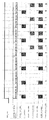
도 4는 본 발명의 다른 측면에 따른, 2-포인터 HDR 이미지 센서 리드아웃 및 셔터 타이밍 기법의 도식적 표현이다.
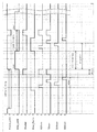
도 5는 본 발명의 다른 측면에 따른, 2-포인터 HDR 이미지 센서 리드아웃 및 셔터 타이밍 기법의 도식적 표현이다.
도 6은 본 발명의 다른 측면에 따른, 롤링 셔터 리드아웃 기법을 위한 타이밍 다이어그램의 도식적 표현이다.BRIEF DESCRIPTION OF THE DRAWINGS For a fuller understanding of the principles and advantages of the present invention, reference is made to the following detailed description of the preferred embodiments, taken in conjunction with the accompanying drawings.
1 is a block diagram of a four transistor COMS image sensor pixel according to an aspect of the present invention.
Figure 2 illustrates a method for providing blooming prevention in accordance with another aspect of the present invention.
Figure 3 illustrates a method for providing blooming prevention in accordance with another aspect of the present invention.
Figure 4 is a schematic representation of a two-pointer HDR image sensor lead-out and shutter timing scheme, according to another aspect of the present invention.
5 is a graphical representation of a two-pointer HDR image sensor lead-out and shutter timing scheme, according to another aspect of the present invention.
Figure 6 is a schematic representation of a timing diagram for a rolling shutter lead-out technique, in accordance with another aspect of the present invention.
본 서에서 본 발명이 설명되기 전에, 본서에 설명되는 특정 구조, 프로세스 단계 또는 물질은 제한적이지 않으며, 당업자에 의해 인지될 수 있는 그것들의 등가물로 확장될 수 있음이 이해되어야 한다. 또한 본서에서 채용되는 전문용어는 오직 특정 실시예를 설명하기 위한 목적으로만 이용되며 제한적 의도가 아님이 이해되어야 한다.Before the present invention is described herein, it is to be understood that the particular structure, process steps or materials described in this document are not limiting, and may be extended to their equivalents as may be recognized by one of ordinary skill in the art. It is also to be understood that the terminology employed herein is for the purpose of describing particular embodiments only and is not intended to be limiting.
정의Justice
다음의 전문용어는 아래의 정의에 따라 이용된다.The following terminology is used in accordance with the following definitions.
명세서 및 청구항에서 이용되는 바와 같이, "어떤", "그"와 같은 관사는 본문에서 명확하게 가리키지 않는 한 복수의 대상을 포함한다. 따라서, 예를 들어 "어떤 픽셀"의 기재는 적어도 하나의 픽셀을, "그 셔터"의 언급은 적어도 하나의 셔터를 포함한다.As used in the specification and claims, "a" and "an" include plural referents unless the context clearly dictates otherwise. Thus, for example, the description of "some pixel" includes at least one pixel, and the reference to "its shutter"
본 출원에서 "포함하고(comprises)", "포함하는(comprising)", "함유하는(containing)", 및 "가지는(having)" 등 이와 비슷한 종류의 것은 미국 특허법에서 부여된 의미를 가질 수 있고, "포함하고(includes)", "포함하는(including)" 등 이와 비슷한 뜻을 지나고, 일반적으로 제한되지 않게 해석된다. "구성하는(consisting of)", "구성하고(consists of)" 용어는 제한적인 용어이고, 미국 특허법에 의한 것뿐만 아니라 특별히 이런 용어와 연관되어 나열되는 성분, 구조, 단계 등 이와 비슷한 종류의 것만을 포함한다. "필수적으로 구성하고(Consisting essentially of)" 또는 "필수적으로 구성하는(consists essentially of)"은 미국 특허법에 의해 일반적으로 부여된 의미를 가진다. 특히, 이런 용어는 일반적으로 제한적인 용어이고, 추가의 항목, 물질, 성분, 단계 또는 요소를 포함하는 예외를 가지고, 이런 것들과 연관되어 이용되는 항목(들)의 기능 또는 기본적이고 새로운 특성에 실질적으로 영향을 주지 않는다. 예를 들어, 구성에 존재하지만 구성의 본질 또는 특성에 영향을 주지 않는 미량 원소는 비록 이런 전문용어를 따르는 항목의 리스트에 명시적으로 언급되지 않았더라도 "필수적으로 구성하는" 언어 하에서 존재하는 경우 허용될 수 있다. "포함하는(comprising)" 또는 "포함하는(including)"과 같은 제한적이지 않은 용어를 이용하는 경우, 직접적인 지원(direct support)은 또한 마치 명시적으로 언급한 것처럼 "구성하는" 뿐만 하니라 "필수적으로 구성하는"까지 가져올 수 있고, 반대의 경우도 마찬가지이다. 추가로, 구성, 종류 또는 그룹 내에 이와 유사한 것은 편의의 목적으로 행해질 수 있고 이러한 그룹은 완전한 것으로 해석되지 않고 문헌에서 다르게 언급하지 않는 한 그룹의 다른 멤버 없이 개인적으로 분리되어 그룹의 각각의 멤버가 연결된 것임이 이해되어야 한다. 이는 본 출원의 청구항 및 명세서 모두에서 포함된 정확한 그룹이다. 추가로 그룹의 어떤 개별적 멤버도 별도의 지시 없이 일반적인 그룹에서 그들의 존재에 기반하여 단독으로 동일한 그룹의 다른 멤버와 사실상의 등가로 해석되지 않는다.The terms "comprises", "containing", "containing", and "having" in this application may have the meanings assigned to it by U.S. Patents , "Includes", "including", and the like, and is generally interpreted without limitation. The terms " consisting of " and " consists of "are a limiting term and are intended to encompass not only those of the United States Patent Act, but also of components, structures, . "Consisting essentially of" or "consists essentially of" has the meaning generally assigned by U.S. patent law. In particular, such terms are generally used as terms of terminology, with the exception of additional items, materials, components, steps or elements, and are intended to cover substantially all of the functions or basic and novel characteristics of the item (s) Lt; / RTI > For example, trace elements that are present in a composition but do not affect the nature or characteristics of the composition are allowed if they exist under the language "essentially composed", even if they are not explicitly mentioned in the list of items that follow these terms . When using non-limiting terms such as "comprising" or "including", direct support is also referred to as "constructing only" as if explicitly stated. To do ", and vice versa. In addition, similar arrangements within a structure, type, or group may be made for the purpose of convenience, and such groups are not to be interpreted as being perfect, and unless individually expressly stated otherwise in the literature, each member of the group is individually Should be understood. Which is an exact group included in both the claims and the specification of this application. In addition, no individual member of the group is interpreted as being substantially equivalent to other members of the same group solely on the basis of their presence in the general group without further instruction.
본서에서 이용된 바와 같이 "실질적으로" 용어는 행동, 특성, 성질, 상태, 구조, 항목, 또는 결과의 완전하거나 거의 완전한 확대 또는 정도를 참조한다. 예를 들어, "실질적으로" 포함되는 객체는 객체가 완전히 포함되거나 거의 완전히 포함되는 것을 의미한다. 절대적인 완전으로부터 벗어나는 것의 정확히 허용되는 정도는 일부 경우에서 특별한 문맥에 의존한다. 그러나, 일반적으로 언급되는 완전함의 근접함은 절대적이고 전체 완성이 획득되는 것처럼 동일한 전체 결과를 가지는 것이기 위함일 수 있다. "실질적으로"의 이용은 행동, 특성, 성질, 상태, 구조, 항목, 또는 결과의 완전하거나 거의 완전한 결핍을 언급하는 부정적 함축에 이용되는 경우 등가적으로 적용될 수 있다. 예를 들어 입자가 "실질적으로 없는" 구성은 완전히 입자가 결핍일 수 있거나 마치 입자가 완전이 결핍된 것과 동일할 수 있는 효과를 내며 거의 입자가 결핍일 수 있다. 다르게 설명하면 재료 또는 요소가 "실질적으로 없는" 구성은 이런 항목을 실제로 포함하였지만, 이것들의 의미 있는 효과가 없는 경우일 수 있다.The term "substantially" as used herein refers to the complete or almost complete enlargement or extent of an action, characteristic, nature, condition, structure, item, or result. For example, an object that is "substantially" included means that the object is fully or almost entirely contained. The precise degree of exclusion from absolute perfection depends on the particular context in some cases. However, the proximity of the generally mentioned completeness may be absolute and to have the same overall result as the complete completion is obtained. Use of "substantially" is equally applicable when it is used for negative connotations that refer to a complete or almost complete lack of behavior, property, nature, condition, structure, item, or result. For example, a composition that is "substantially free" of particles may be completely deficient in the particles, or almost as if the particles are deficient in perfection. In other words, configurations in which a material or element is "substantially absent " actually include such items, but these may not have a meaningful effect.
본서에 이용된 바와 같이, "약"이란 용어는 주어진 값이 엔드포인트(endpoint)에서 "조금 위" 또는 "조금 아래"일 수 있는 경우 수치적 범위의 엔드포인트에서 유연성을 제공하기 위해 이용된다.As used herein, the term "about" is used to provide flexibility in a numerical range of endpoints where a given value may be "slightly above" or "slightly below"
농도, 양, 및 다른 수치적 데이터는 본서에서 범위의 포맷으로 제시되거나 설명될 수 있다. 이러한 범위의 포맷은 단순히 편의와 단순의 이유로 이용되며 이에 따라 마치 각각의 수치 값 및 하부 범위가 명시적으로 언급된 것처럼 범위의 제한으로 명시적으로 언급되는 수치 값을 포함할 뿐만 아니라, 그 범위 내에 포함되는 하부 범위 또는 모든 개개의 수치 값을 포함하는 것으로 해석되어야 한다. 예를 들어, 수치 범위 "약 1부터 5까지"는 약 1부터 5까지의 명시적으로 언급된 값뿐만 아니라, 지시되는 범위 내의 개개의 값 및 하부 범위까지 포함하는 것으로 해석되어야 한다. 따라서, 개개의 1, 2, 3, 4, 및 5뿐만 아니라 1-3, 2-4, 2-5 등과 같은 하부 범위 및 개개의 2, 3, 및 4와 같은 값들이 이런 수치의 범위에 들어간다.Concentrations, amounts, and other numerical data may be presented or described in a range of formats in this document. This range of formats is used merely for convenience and simplicity, so that not only does each numerical value and sub-range include numerical values explicitly referred to as a range limitation, such as explicitly stated, Quot; is to be construed as including sub-ranges or all individual numerical values. For example, the numerical range "about 1 to 5" should be construed to include not only explicitly stated values from about 1 to 5, but also individual values and subranges within the indicated ranges. Thus, values such as subranges such as 1-3, 2-4, 2-5, and
이와 동일한 원리가 최소 또는 최대로서 하나의 수치값을 언급하는 범위에 적용된다. 추가로 이러한 해석은 설명되는 특성 또는 범위의 폭과 상관없이 적용될 수 있다.The same principles apply to ranges that refer to a single numerical value as a minimum or a maximum. In addition, such interpretation can be applied regardless of the width of the characteristic or range being described.
발명의 개시DISCLOSURE OF INVENTION
본 발명은 CMOS 이미저를 사용하는 고 동적 범위(high dynamic range; HDR)의 이미지를 캡쳐하는 것에 이용되는 시스템, 방법, 및 장치를 제시한다. 보다 특정하게는 다른 집적 시간에서 캡쳐되는 이미지 사이에서 셔터링의 중요한 이용을 통해 제공되는 블루밍 방지가 제공된다. 이런 새로운 테크닉은 예를 들어 롤링 셔터 CMOS 이미저와 같은 임의의 행 방식의 HDR CMOS 이미저에 적용되어 블루밍 문제를 줄일 수 있다.The present invention provides a system, method and apparatus for use in capturing images of high dynamic range (HDR) using a CMOS imager. More particularly, blooming prevention is provided through an important use of shuttering between images captured at different integration times. This new technique can be applied to any row of HDR CMOS imagers, such as, for example, rolling shutter CMOS imagers, to reduce blooming problems.
CMOS 이미지 센서는 일반적으로 행렬로 배열된 픽셀 배열을 포함한다. 각각의 픽셀은 일반적으로 포토다이오드 및 전달 게이트를 포함하고, 이는 포토다이오드로부터 수집된 전하의 전달을 제어하기 위한 이미지 리드아웃에서 이용된다. 이미저는 복수의 픽셀(즉, 일부 측면에서 적어도 하나의 픽셀 행), 행 선택 트랜지스터, 및 이들 사이를 셔터 또는 리셋하는 것에 이용되는 리셋 게이트를 포함한다. CMOS 이미저는 공지된 성분 같은 종래의 기술에서 잘 알려져 있고, 행 방식의 리드아웃 기법을 이용하는 이미저로 통합되는 디자인은 본 발명의 범위 내에 통합될 수 있다. 예를 들어, 네 개의 트랜지스터(4T), 5T, 또는 그 이상을 가진 CMOS 이미저가 이용될 수 있다. 4T CMOS 이미저의 제한적이지 않은 예시가 도 1에 도시된다. 이러한 장치는 포토다이오드(102), 전달 트랜지스터(104), 플로팅 확산 영역(106), 리셋(108), 소스 팔로어(110), 행 선택(112), 픽셀 배열을 위한 파워 서플라이 전압(114), 및 전압 출력(116)을 포함할 수 있다.CMOS image sensors typically include a pixel array arranged in a matrix. Each pixel typically includes a photodiode and a transfer gate, which is used in an image lead-out to control the transfer of charge collected from the photodiode. The imager includes a plurality of pixels (i.e., at least one row of pixels in some aspects), a row select transistor, and a reset gate used for shutting or resetting therebetween. CMOS imagers are well known in the prior art, such as known components, and designs incorporating imagers that utilize row-wise lead-out techniques can be incorporated within the scope of the present invention. For example, a CMOS imager with four transistors (4T), 5T, or more can be used. A non-limiting example of a 4T CMOS imager is shown in FIG. This device includes a
롤링 셔터로서도 알려진 행 방식의 리드아웃은 픽셀이 입사광에 노출되는 시간을 제어하는 CMOS 이미지의 메커니즘으로서 종종 이용된다. 롤링 셔터는 픽셀의 레벨을 작동하는 전자 셔터이고, 행에 따른 픽셀 배열을 따라 전진한다. 행이 셔터가 되는 것으로 선택되는 경우, 리셋 전압은 리셋 트랜지스터를 경유하여 픽셀에 적용되고 전압은 전달 게이트에 적용되고, 이에 따라 픽셀의 광다이오드의 내용이 지워지고 리셋 상태에 픽셀이 놓여진다. 리셋 상태에 있는 동안, 픽셀은 유입되는 광자로부터 전하를 축적하지 않는다. 일단 리셋 전압 및 전달 게이트 전압이 지워지면, 픽셀은 유입되는 광자를 흡수할 수 있고 광자에 따른 전하를 축적할 수 있다. 전형적인 롤링 셔터 프로세스의 제한적이지 않은 예시에서, 이미저의 픽셀 행은 시퀀스에서 리셋될 수 있고, 배열의 상단에서 행에 따라 전진하며 배열의 하단으로 출발할 수 있다. 그러나 롤링 셔터 프로세스는 배열의 임의 포인트에서 다른 곳으로 이동할 수 있고 이는 예시적일 뿐이다. 일단 리셋 동작이 픽셀의 행을 지나 이동하면 전하 축적이 시작된다. 주어진 집적 시간을 따라, 사용자의 장치에 의해 세팅된 리드아웃 동작이 시작된다. 행은 롤링 셔터의 순서가 각각의 행의 일정한 집적 시간을 유지하기 위해 픽셀 배열을 리드아웃할 수 있다. 따라서, 픽셀 배열의 노출 시간은 롤링 셔터의 통과와 배열 행의 리드아웃 사이의 타이밍 차이에 의해 제어된다. 이런 노출 시간은 종종 집적 시간으로서 언급된다. 집적 시간의 증가는 픽셀이 전하를 축적하는 기간을 증가시키지만, 집적시간의 감소는 전하 축적을 감소시킨다.A row-wise lead-out, also known as a rolling shutter, is often used as a mechanism of a CMOS image to control the time a pixel is exposed to incident light. A rolling shutter is an electronic shutter that actuates the level of a pixel and advances along a pixel array along a row. When the row is selected to be a shutter, the reset voltage is applied to the pixel via the reset transistor and the voltage is applied to the transfer gate, thereby erasing the content of the photodiode of the pixel and placing the pixel in the reset state. While in the reset state, the pixel does not accumulate charge from the incoming photons. Once the reset voltage and transfer gate voltage are erased, the pixel can absorb the incoming photons and accumulate the charge associated with the photons. In a non-limiting example of a typical rolling shutter process, the rows of pixels of an imager can be reset in a sequence, advanced at a row at the top of the array, and start at the bottom of the array. However, the rolling shutter process can move from any point in the array to another, which is exemplary only. Once the reset operation moves past the row of pixels, charge accumulation begins. Following the given integration time, the lead-out operation set by the user's device is initiated. The rows can lead out the pixel array in order for the rolling shutter sequence to maintain a constant integration time of each row. Thus, the exposure time of the pixel array is controlled by the timing difference between the passage of the rolling shutter and the lead-out of the array row. Such exposure times are often referred to as integration times. An increase in integration time increases the period over which pixels accumulate charge, but a decrease in integration time reduces charge accumulation.
통상의 한 문제가 이미지를 캡쳐할 때, 특히 긴 집적 시간 생길 수 있고, 이는 "블루밍(blooming)"으로 참조된다. 픽셀은 제한된 전하 웰 커패시티를 가지고 있고, 이에 따라 오직 제한된 양의 전하만 축적할 수 있다. 이런 웰(well)이 가득 차면, 특히 픽셀이 광자를 전하로 바꾸는 경우, 초과 전하는 이웃한 픽셀로 넘칠 수 있고, 이에 따라 이런 픽셀에서 관련 전하 농도에 오류를 일으키게 한다. 이런 네커티브 효과는 픽셀의 다중 행을 넘치게 할 수 있고, 블루밍의 소스 및 영향을 받는 행, 픽셀 사이즈, 에피택시 층의 두께 등 사이에서 대응하는 전하에 의존한다. 이는 특히 어두운 곳에서 자동차 전조등처럼 어두운 배경에서의 밝은 빛을 가진 이미지 장면과 같은 문제가 될 수 있다. 따라서 이런 블루밍은 이미지의 일부 부분에서 원치 않는 노이즈를 야기하며 퍼져나간다.When a typical problem captures an image, especially long integration times, it is referred to as "blooming ". The pixel has a limited charge well capacity, and thus can accumulate only a limited amount of charge. When such a well is full, especially when a pixel turns a photon into a charge, the excess charge can overflow with neighboring pixels, thereby causing an error in the associated charge concentration at such a pixel. This negative effect can overflow multiple rows of pixels and depends on the source of blooming and the corresponding charge between the affected rows, the pixel size, the thickness of the epitaxial layer, and so on. This can be an especially problematic image scene with bright light in a dark background, such as a car headlight in the dark. Thus, this blooming spreads in some parts of the image causing unwanted noise.
전술된 바와 같이, 다중의 노출 이미지는 CMOS 기술을 가진 HDR(high dynamic range) 이미지를 생성하는 하나의 테크닉이다. HDR 이미지는 정상의 이미지 기술과 비교했을 때 주어진 장면의 가장 밝은 영역과 가장 어두운 영역 사이에서 더 큰 동적 범위를 캡쳐한다. 일반적인 HDR 장면은 밤의 자동차 전조등의 조명처럼 장면의 객체 사이에서 빛의 강도의 큰 대비가 있는 경우 생긴다. 다중의 노출 HDR 기법에서, 다중의 이미지는 동일한 장면의 각각의 프레임의 다른 집적 시간에서 획득된다. 다음으로, 다중의 이미지는 마지막 이미지를 재구축하기 위해 결합된다. 전형적으로, 다중의 노출 HDR 기법은 프레임 방식 또는 행 방식일 수 있다. 프레임 방식의 HDR 기법에서, 두 개 (또는 그 이상의) 프레임들이 순차적으로 리드아웃될 수 있고, 이는 전체 초점의 평면 배열이 적어도 두 번 리드아웃되어 HDR 이미지를 생성하기 위해 결합되는 것을 의미한다. 제1 프레임은 노출 시간을 알려진 미리 정해진 집적 시간을 가질 수 있고, 제2 프레임은 미리 정해진 집적 시간을 가질 수 있다. 전형적으로 장면의 낮은 빛의 강도를 캡쳐하는 프레임은 주어진 장면의 높은 강도 또는 정상적인 빛의 강도를 캡쳐하는 프레임보다 긴 노출 또는 집적 시간을 가진다. 일단 두 개의 프레임으로부터 로우 이미지 데이터가 리드아웃되면, 이것들은 HDR 이미지를 생성하기 위해 결합된다. 반면에, 행 방식의 HDR 이미지에서 모든 행은 단일 프레임 이미지에서 다중 횟수 리드아웃되고, 각각의 리드아웃에서 집적 시간을 가지고, 이는 일부 경우에 다른 집적 시간일 수 있다. 예를 들어, 세 개의 노출 HDR 리드아웃 기법에서 각각의 행은 다른 집적 시간에서 세 번 리드 아웃된다. 마지막 HDR 이미지를 재구축하기 위해, 행 방식의 HDR로부터의 행 이미지 데이터는 개개의 프레임 데이터로 먼저 분리된다. 프레임 방식과 행 방식의 HDR 접근 모두 확장된 동적 범위에 대해 유연하고 최소의 디자인 변경으로 대부분의 CMOS 이미저에 적용될 수 있다. 그러나 두 디자인 모두 마지막 이미지의 재구축 이전에 이미지 데이터를 저장하기 위해 온칩 또느 오프칩을 이용할 수 있다.As described above, multiple exposure images are one technique for generating high dynamic range (HDR) images with CMOS technology. An HDR image captures a larger dynamic range between the lightest and darkest areas of a given scene when compared to normal image technology. A typical HDR scene occurs when there is a great contrast of the intensity of light between objects in the scene, such as nighttime car headlights. In multiple exposure HDR techniques, multiple images are acquired at different integration times of each frame of the same scene. Next, multiple images are combined to reconstruct the last image. Typically, multiple exposure HDR techniques may be frame-wise or row-wise. In a frame-wise HDR scheme, two (or more) frames can be sequentially read out, which means that the planar array of full focuses is lead out at least twice to combine to produce an HDR image. The first frame may have a predefined integration time with known exposure time, and the second frame may have a predetermined integration time. Typically, a frame that captures the intensity of low light in a scene has a longer exposure or integration time than a frame that captures the high intensity of a given scene or the intensity of a normal light. Once the raw image data is read out from the two frames, they are combined to produce an HDR image. On the other hand, in a row-wise HDR image, all rows are lead out multiple times in a single frame image and have an integration time in each lead-out, which may be some other integration time in some cases. For example, in a three-exposure HDR lead-out technique, each row is read out three times at different integration times. To reconstruct the last HDR image, the row image data from the row-wise HDR is first separated into individual frame data. Both frame-wise and row-wise HDR approaches are flexible for the extended dynamic range and can be applied to most CMOS imagers with minimal design changes. Both designs, however, can use on-chip or off-chip storage of image data prior to rebuilding the final image.
행 방식의 HDR 이미지 기법의 한 실시예는 롤링 셔터를 이용하는 긴 집적 시간 노출을 가지는 제1 이미지 프로세스로 시작되고, 짧은 집적시간을 가지는 제2 이미지 프로세서는 제1 이미지의 리드아웃에 뒤이어 시작된다. 긴 집적 시간 이미지에서 블루밍이 일어난 경우에, 이런 블루밍 전하는 짧은 집적 시간을 가지는 제2 이미지로 리셋 픽셀을 교차할 수 있고, 이에 따라 원치 않는 노이즈가 유발된다. 하나의 예로서 롤링 셔터의 하나의 행의 폭이 픽셀 배열을 가로질러 진행하고, 집적을 시작한다고 가정하자. 100개의 행 집적 시간의 마지막에, 각각의 행이 리드아웃되고 제2 롤링 셔터와 함께 리셋되고, 다시 하나의 행의 혹이 짧은 3번의 집적 시간동안 픽셀의 집적을 시작한다. 이 경우에, 긴 집적 시간 동안 아직 리드아웃되지 않은 행은 블룸되기에 충분한 전하를 가진 웰을 가질 수 있고, 이는 행의 리드아웃에 앞서 제2 롤링 셔터를 크로스할 수 있고, 짧은 집적을 지난 픽셀에서 전하의 교란을 유발할 수 있다.One embodiment of a row-based HDR imaging technique begins with a first image process with a long integration time exposure using a rolling shutter and a second image processor with a short integration time begins following a lead-out of the first image. In the event of blooming in a long integration time image, this blooming charge can cross the reset pixel with a second image having a short integration time, thereby causing unwanted noise. As an example, assume that the width of one row of rolling shutters proceeds across the pixel array and begins to accumulate. At the end of 100 row integration times, each row is read out and reset together with the second rolling shutter, and again the integration of pixels for one to three integration times of one row is started. In this case, the rows that have not yet been led out during the long integration time may have wells with enough charge to be bloomed, which may cross the second rolling shutter prior to lead-out of the row, Lt; RTI ID = 0.0 > disturbance. ≪ / RTI >
본 기술은 긴 집적 시간의 이미지의 리드아웃을 따라 리셋되거나 셔터되는 행을 가로지르는 블루밍을 제한하는 셔터링의 중요한 이용을 통해 이런 의도되지 않은 블루밍을 제거하거나 줄인다. 이런 중요한 셔터링은 예를 들어 셔터되는 행 숫자의 변화, 셔터되는 행 패턴, 셔터링 전압의 일시적 변화 등 이와 유사한 것 등의 다양한 방법에 의해 성취된다. 일측에서, 셔터되는 행의 수는 증가되어 다른 하나에 직접적으로 인접한다. 이런 경우에, 긴 집적 시간의 리드아웃은 2, 3, 4 이상의 행의 폭인 셔터를 따라 증가한다. 이렇게 확대되는 셔터를 따라, 리셋은 제거되고 픽셀은 짧은 집적 시간 동안 집적하는 것이 허용된다. 이에 따라, 긴 집적 시간 영역에서 리드아웃되지 않은 전하 웰을 가득 가지고 있는 픽셀로부터의 전하가 방지되고 다중의 행 셔터를 크로스 하는 것이 제한되며, 다중의 행이 리셋 상태에 놓인다. 예를 들어 4개의 행이 셔터되는 경우에, 주어진 행은 긴 집적 시간 이미지에서 리드아웃되고, 다음의 3행의 리드아웃을 위해 존재하는 리셋이 뒤따른다. 다음으로 주어진 행에서의 리셋이 해제되고, 짧은 집적 시간이 시작된다. 마지막 행의 리드아웃이 셔터되고 4 행의 롤링 셔터가 행 방식의 방법에서 픽셀 배열을 가로질러 이동하고, 이에 따라 짧은 시간 영역에서 블룸 방지가 제공된다. 짧은 집적 시간의 시작은 리셋의 폭 때문에 종해의 롤링 셔터에 비해 지연될 수 있다.The technique eliminates or reduces this unintended blooming through an important use of shuttering to limit blooming across a row being reset or shuttered along the lead-out of images of long integration time. This important shuttering is achieved by various methods such as, for example, a change in the number of rows to be shuttered, a row pattern to be shuttered, a temporal change in the shuttering voltage, and the like. On one side, the number of rows being shuttered is increased and is directly adjacent to the other. In this case, the lead-out of the long integration time increases along a shutter that is 2, 3, 4 or more rows wide. Along this enlarged shutter, the reset is removed and the pixels are allowed to accumulate for a short integration time. Thus, charge from pixels that are full of charge wells that have not been led out in the long integration time region is prevented and crossing multiple row shutters is limited, and multiple rows are placed in the reset state. For example, if four rows are to be shuttered, a given row is read out in a long integration time image, followed by a reset for the next three rows of readout. Next, the reset on the given row is released, and the short integration time begins. The lead-out of the last row is shut off and the four-row rolling shutter moves across the pixel array in a row-wise fashion, thereby providing bloom protection in the short time domain. The start of the short integration time can be delayed compared to the rolling shutter of the last due to the width of the reset.
추가로, 본 기술은 두 개의 집적 시간을 가지는 HDR에 국한되지 않을 뿐만 아니라, 다른 집적 시간을 가지는 제3, 제4 또는 그 이상의 이미지에 적용될 수 있는 동일하거나 유사한 이미징 프로세스이다. 따라서, 전술된 예시에서 주어진 행이 제2 집적 시간 동안 리드 아웃되는 경우, 행은 제3 집적 이미지에 대한 블룸 방지를 제공하는 특성을 가진 셔터와 함께 리셋될 수 있다.In addition, the technique is not limited to HDRs having two integration times, but is an identical or similar imaging process that may be applied to third, fourth, or more images having different integration times. Thus, in the example described above, if a given row is read out during a second integration time, the row may be reset with a shutter having the property of providing bloom protection for the third integrated image.
다양한 셔터의 구성 및 셔터의 행동이 고려되어, HDR 이미지에 블루밍 방지를 제공하는 임의의 셔터 기법을 포함할 수 있다. 일반적으로 셔터는 블루밍 방지를 제공하기 위해 동시에 셔터되는 적어도 두 개의 행의 픽셀을 가진다. 일측에서 전술된 바와 같이 셔터는 2, 3, 4, 5, 또는 그 이상의 직접적으로 인접한 행을 가로질러 적용될 수 있다. 다른 측면에서, 셔터는 2, 3, 4, 5, 또는 그 이상의 직접적으로 인접하지 않은 행에 적용되거나, 동일한 셔터 내에서 직접적으로 인접한 행 및 직접적으로 인접하지 않은 행을 포함할 수 있다. 예를 들어, 4 개의 행 셔터는 행 10, 11, 12 및 13에 적용될 수 있거나 4 개의 행 셔터는 행 10, 12, 14 및 16에, 또는 행 10, 13, 14 및 17에 적용될 수 있거나, 또는 임의의 다른 조합이 블루밍 방지에 이용될 수 있다.The configuration of the various shutters and the behavior of the shutters may be considered and may include any shutter technique that provides anti-blooming to the HDR image. Generally, the shutter has at least two rows of pixels that are simultaneously shuttered to provide blooming protection. The shutters can be applied across 2, 3, 4, 5, or more directly adjacent rows, as described above. In another aspect, the shutters may be applied to two, three, four, five, or more non-directly adjacent rows, or may include directly adjacent rows and non-directly adjacent rows within the same shutter. For example, a four row shutter may be applied to
전술된 바와 같이, 블루밍의 기회는 블루밍의 소스와 영향 받는 행, 픽셀 사이즈, 에피택셜 층의 두께 등의 사이의 연관 전하에 의존하여 다양해질 수 있다. 이러한 셔터 구성은 이러한 인자를 설명하기 위해 디자인될 수 있다. 일측에서, 현재 기술은 약 1부터 10 마이크론까지의 에피택셜 층의 두께를 이용할 수 있고, 약 0.9부터 약 30 마이크론까지, 또는 0.9부터 약 6마이크론까지, 또는 0.9부터 약 3까지의 픽셀 사이즈를 가질 수 있고, 일부 제한되지 않는 예시를 지정할 수 있다. 픽셀의 사이즈가 감소할수록, 블루밍을 감소시키거나 방지하기 위해 셔터되는 행의 개수는 증가될 필요가 있다. 예를 들어, 0.9 마이크론 픽셀에서, 일부 경우에 셔터는 30행까지 증가될 수 있다. 그러나 본 발명의 구성에서 이러한 변형을 계산하기 위해 필요한 셔터의 지속 시간은 당업자에 의해 쉽게 계산된다.As described above, the chance of blooming can vary depending on the source of blooming and the associated charge between the affected row, the pixel size, the thickness of the epitaxial layer, and the like. This shutter configuration can be designed to account for these factors. On one side, current techniques can utilize the thickness of the epitaxial layer from about 1 to 10 microns and have pixel sizes from about 0.9 to about 30 microns, or from 0.9 to about 6 microns, or from 0.9 to about 3 And some non-limiting examples may be specified. As the size of the pixel decreases, the number of rows being shuttered needs to be increased to reduce or prevent blooming. For example, at 0.9 micron pixels, in some cases the shutter can be increased to 30 rows. However, the duration of the shutter required to compute this variation in the configuration of the present invention is easily calculated by those skilled in the art.
추가로 다양한 셔터의 행동이 고려되고, 디자인 및/또는 장치의 복잡성에 의존하여 변할 수 있다. 일측에서 장치는 고정된 셔터 기법을 가질 수 있다. 예를 들어, 셔터는 이미징 조건과 상관없이 장치의 4행의 폭에서 고정될 수 있다. 다른 측면에서, 장치의 셔터는 주어진 이미지 또는 이미지 조건에 따라 이용자에 의해 수동으로 설정될 수 있다. 다른 측면에서, 장치는 자동 모드를 포함할 수 있고, 이 경우 셔터 특성은 조명 조건에 맞춰 자동으로 설정된다. 추가로, 혼합의 접근이 고려되어 사용자가 원하는 방식으로 동작하도록 장치가 설정되고, 장치는 사용자에 의해 설정된 파라미터 내의 최적 또는 최적에 가까운 조건으로 자동으로 설정되거나 셔터의 특성을 변화시킨다. In addition, the behavior of the various shutters is contemplated and may vary depending on the design and / or the complexity of the device. On one side the device may have a fixed shutter technique. For example, a shutter can be fixed in the width of four rows of the device, regardless of imaging conditions. In another aspect, the shutter of the device may be manually set by the user according to a given image or image condition. In another aspect, the device may include an automatic mode, in which case the shutter characteristic is automatically set to match the illumination condition. In addition, the approach of mixing is taken into account and the device is set to operate in a manner desired by the user, and the device is automatically set to optimal or near optimal conditions within the parameters set by the user or changes the characteristics of the shutter.
셔터는 주어진 프레임 또는 이미지 프로세스 내에서 추가로 변할 수 있다. 예를 들어 일측에서 장치는 긴 집적 시간 프로세스와 중간 집적 시간 프로세스 사이에서 셔터의 지속 기간을 증가시킬 수 있지만, 중간 집적 시간 프로세서와 짧은 집적 시간 프로세스 사이에서 셔터의 지속 기간을 감소시킬 수 있다. 따라서, 셔터의 지속 기간은 블루밍 문제를 가질 수 있는 이미지 섹션 사이의 HDR 이미지 캡쳐 기간 동안 증가될 수 있지만, 블루밍을 경험할 수 없을 것 같은 이미지 섹션 사이에서 감소될 수 있다. 일부 장치에서 이런 동작이 고정되는 반면에, 다른 측면에서 장치는 셔터 기간을 동적으로 증가시키기 위해 로직을 포함할 수 있거나 블루밍이 검출되거나 블루밍이 일어날 수 있는 장면이 검출되는 경우에 주어진 셔터 패턴을 적용할 수 있다. 따라서, 로직은 집적 시간 이미지 사이에서 동적으로 셔터를 조정할 수 있거나, 일부 측면에서 주어진 집적 시간 동안 주어진 롤링 셔터의 동작을 조정할 수 있다. 이미지가 긴 집적 시간 동안 리드아웃되어 블루밍의 가능성이 검출되는 경우, 예를 들어 로직은 블루밍의 발생을 막거나 제한하기 위해 셔터를 조정할 수 있다.The shutter may further change within a given frame or image process. For example, on one side the device can increase the duration of the shutter between the long integration time process and the intermediate integration time process, but it can reduce the duration of the shutter between the intermediate integration time processor and the short integration time process. Thus, the duration of the shutter may be increased during the HDR image capture period between image sections that may have blooming problems, but may be reduced between image sections that are unlikely to experience blooming. While this behavior is fixed in some devices, in other aspects the device may include logic to dynamically increase the shutter duration, or may apply a given shutter pattern when a scene where blooming is detected or blooming may be detected can do. Thus, the logic can dynamically adjust the shutter between the integrated time images, or in some aspects, adjust the operation of a given rolling shutter during a given integration time. If the image is read out during long integration times and the likelihood of blooming is detected, for example, the logic may adjust the shutter to prevent or limit the occurrence of blooming.
추가로, 일부 측면에서 리셋의 강도(즉, 인가된 전압)는 주어진 셔터의 지속 기간을 통해 일정할 수 있고, 반면에서 다른 측면에서 셔터의 강도는 변할 수 있다. 예를 들어, 하나의 에너지 절약 기술은 셔터가 적용될 때 하드 리셋하는 것일 수 있고, 셔터의 중간 동안 리셋 전압을 낮추고, 다음의 집적 주기가 시작하기 이전에 다시 행을 하드 리셋하는 것일 수 있다. 셔터 강도의 변화는 장치에서 고정될 수 있고, 사용자 및/또는 장치에 의해 동적으로 제어되며 설정될 수 있다. 동적으로 제어되는 경우에, 장치의 로직은 블루밍 또는 블루밍의 가능성을 검출하기 위해 이용될 수 있고, 이에 따라 이러한 블루밍 기간 동안 리셋의 강도를 증가시킬 수 있고 블루밍의 가능성이 낮아지는 경우에 강도를 낮출 수 있다.In addition, in some aspects, the intensity of the reset (i. E., The applied voltage) may be constant over the duration of a given shutter, while on the other side the intensity of the shutter may vary. For example, one energy saving technique may be to hard reset when the shutter is applied, lower the reset voltage during the middle of the shutter, and then hard reset the row again before the next integration period begins. The change in shutter intensity can be fixed in the device and dynamically controlled and set by the user and / or device. When dynamically controlled, the logic of the device may be used to detect the likelihood of blooming or blooming, thereby increasing the intensity of the reset during this blooming period and lowering the intensity if the probability of blooming is low .
도 2에 도시된 바와 같이, 하나의 예시적인 방법은 행렬로 배열되는 복수의 픽셀의 픽셀 배열을 가지는 CMOS 이미저에 블루밍 방지를 제공하고, CMOS 이미저는 롤링 셔터를 이용하는 높은 동적 범위의 이미지를 캡쳐하기 위해 동작 가능하다. 방법은 픽셀의 리드아웃 행을 선택하는 단계(202), 리드아웃 행에서 픽셀의 제1 집적 시간을 시작하는 단계(204), 제1 리드아웃을 획득하는 리드아웃 행에서 픽셀에 의해 축적되는 전하를 리드아웃하는 단계(206)를 포함할 수 있다. 방법은 또한 리드 아웃 및 리셋이 적어도 하나의 후속 행에서 발생하기에 충분한 리셋 시간 동안 리드아웃 행에 리셋을 적용하는 단계(208), 리드아웃 행에서 픽셀의 제2 집적 시간을 시작하고 리셋을 제거하는 단계(210)를 포함할 수 있고, 제2 집적 시간은 제1 집적 시간보다 짧고, 적어도 하나의 후속 행은 결합되는 리셋을 제2 집적 시간 동안 리드아웃 행에서 픽셀 배열로부터 적어도 실질적으로 블루밍 효과로부터 방지하는 충분한 수의 행이다. 후속 행은 리드아웃되었거나 이어서 프로세스되는 리드아웃 행이다. 리드아웃 및 리셋이 적어도 하나의 후속 행에서 일어나기에 충분한 리셋 시간 동안 리드아웃에 리셋을 적용하는 단계는 적어도 하나의 후속 행이 리드아웃 및 리셋되도록 리셋이 리셋 행에서 적어도 충분한 시간을 주는 것을 이어가도록 허용하는 단계를 포함한다. 따라서, 리드아웃 행의 리셋이 두 개의 후속행을 리드아웃 및 리셋하기에 충분한 시간을 유지하도록 허용함으로써, 세 개의 행 셔터가 구현된다. 따라서, 일측에서 리셋은 적어도 두 개의 후속 행 및 리드아웃 행이 동시에 리셋 또는 리셋 상태에 있기에 충분한 리셋 시간 동안 적용된다. 다른 측면에서, 리셋은 적어도 세 개의 후속 행 및 리드아웃 행이 동시에 리셋되거나 리셋 상태에 있기에 충분한 리셋 시간 동안 적용된다.As shown in Figure 2, one exemplary method provides anti-blooming to a CMOS imager having a pixel array of a plurality of pixels arranged in a matrix, and a CMOS imager captures a high dynamic range image using a rolling shutter Lt; / RTI > The method includes selecting (202) a lead-out row of pixels, starting a first integration time of a pixel in a lead-out row (204), calculating a charge accumulated by the pixel in the lead- (Step 206). The method also includes applying (208) a reset to the lead-out row during a reset time sufficient for the lead-out and reset to occur in at least one subsequent row, starting a second integration time of the pixel in the lead-out row, Wherein the second integration time is shorter than the first integration time and the at least one subsequent row includes a reset that is at least substantially blooming from the pixel array in the lead-out row during the second integration time The number of rows to be prevented from being reduced. The subsequent row is the lead-out row that has been read-out or is subsequently processed. Applying a reset to the lead-out during a reset time sufficient for the lead-out and reset to occur in at least one subsequent row causes the reset to continue to give at least sufficient time in the reset row so that the at least one subsequent row is lead- . Thus, by permitting a reset of the lead-out row to hold sufficient time to lead out and reset two subsequent rows, a three-row shutter is implemented. Thus, a reset on one side is applied during a reset time sufficient for at least two subsequent row and lead-out rows to be in a reset or reset state at the same time. In another aspect, the reset is applied during a reset time sufficient for at least three subsequent row and lead-out rows to be reset simultaneously or in a reset state.
행의 타이밍 관점에서 리셋 및 집적 시간을 설명하는 것은 편리하고, 실제 타이밍 범위를 설명하는 것에 유용할 수 있다. 예를 들어, 일측에서 리드아웃 및 리셋이 적어도 하나의 후속 행에서 발생하기에 충분한 리셋 시간은 약 10 나노초에서 약 50 나노초일 수 있다. 다른 측면에서 리드아웃 및 리셋이 적어도 하나의 후속 행에서 발생하기에 충분한 리셋 시간은 약 0.5 마이크로초에서 약 2 마이크로초일 수 있다. 이해하기 쉽게, 이런 리셋 시간은 집적 기간 및 배열의 가능성 있는 블루밍의 정도에 따라 변할 수 있다. 다른 측면에서, 제1 집적 시간은 약 1 밀리초에서 약 1 초일 수 있고, 제2 집적 시간은 약 10 나노초에서 약 100 밀리초일 수 있다. 또 다른 측면에서, 제1 집적 시간은 20 마이크로초에서 33 밀리초일 수 있고, 제2 집적 시간은 약 1마이크로초에서 약 16 밀리초일 수 있다.Describing reset and integration time in terms of row timing is convenient and may be useful in explaining the actual timing range. For example, a reset time sufficient for lead-out and reset on one side to occur in at least one subsequent row may be from about 10 nanoseconds to about 50 nanoseconds. In another aspect, the reset time sufficient for lead-out and reset to occur in at least one subsequent row may be from about 0.5 microseconds to about 2 microseconds. To make it easy to understand, this reset time can vary depending on the integration period and the degree of possible blooming of the array. In another aspect, the first integration time can be from about 1 millisecond to about 1 second, and the second integration time can be from about 10 nanoseconds to about 100 milliseconds. In another aspect, the first integration time can be from 20 microseconds to 33 milliseconds, and the second integration time can be from about 1 microsecond to about 16 milliseconds.
전술된 바와 같이 본 발명의 범위는 순차적, 비순차적, 인접, 비인접한 셔터링 또는 리셋 기법을 포함할 수 있다. 예를 들어, 일측에서 리드아웃 행 및 적어도 세 개의 후속 행은 순차적으로 인접할 수 있다. 다른 측면에서, 리드아웃 행 및 적어도 세 개의 후속 행은 순차적으로 비인접할 수 있다. 이에 따라 임의 개수의 하나 이상의 후속 행(즉, 2개 이상의 행, 리드아웃 행 및 적어도 하나의 후속 행)에 이와 같은 것이 적용될 수 있다.As described above, the scope of the present invention may include sequential, non-sequential, adjacent, non-adjacent shutter ring or reset techniques. For example, one lead out row and at least three subsequent rows may be sequentially contiguous. In another aspect, the lead-out row and at least three subsequent rows may be sequentially non-collocated. Accordingly, this can be applied to any number of one or more subsequent rows (i.e., two or more rows, a lead-out row, and at least one subsequent row).
추가적으로, 상기 방법이 후속 행에서 반복될 수 있다. 일측에서 예를 들어 방법은 적어도 하나의 후속행, 적어도 두 개의 후속행, 적어도 세 개의 후속행 등에서 반복될 수 있다. 일부 측면에서 적어도 하나의 후속 행은 적어도 실질적으로 픽셀 배열의 모든 픽셀 행이다. 추가로, 장치의 디자인에 의존하여, 행은 다양한 순서에서 리드아웃될 수 있다. 예를 들어, 방법은 순차적인 순서로 픽셀 배열의 적어도 실질적으로 모든 픽셀 배열에서 반복될 수 있다. 이런 순서는 시퀀스로서 직접적으로 인접한 행을 포함할 수 있고, 시퀀스로서 행 및 이와 유사한 것 등을 대체할 수 있다. 대안으로, 방법은 비순차적인 순서의 픽셀 배열의 모든 픽셀 항에서 적어도 실질적으로 반복될 수 있다.Additionally, the method may be repeated in subsequent rows. On one side, for example, the method may be repeated in at least one subsequent row, at least two subsequent rows, at least three subsequent rows, and so on. In some aspects, at least one subsequent row is at least substantially all of the pixel rows of the pixel array. Additionally, depending on the design of the device, the rows may be lead out in various orders. For example, the method may be repeated in at least substantially all pixel arrays of pixel arrays in a sequential order. Such a sequence may include directly adjacent rows as a sequence, and may replace rows and the like as a sequence. Alternatively, the method may be repeated at least substantially in all pixel terms of the pixel array in the non-sequential order.
제1 및 제2 집적 시간에 추가하여, 본 발명은 HDR 이미지를 생성하는 것에 이용되는 제3, 제4, 또는 그 이상의 집적 시간을 포함하는 것이 추가적으로 고려된다. 일측에서 방법은 리드아웃 및 리셋이 적어도 하나의 후속 행에서 발생하기에 충분한 리셋 시간을 위해 제2 리드아웃에 이어 리드아웃 행에 리셋을 적용하는 단계, 리드아웃 행에서 픽셀의 제3 집적 시간을 시작하고 리셋을 제거하는 단계를 추가로 포함할 수 있고, 제3 집적 시간은 제2 집적 시간보다 짧고, 적어도 하나의 후속 행은 결합되는 리셋이 제3 집적 시간 동안 리드아웃 행의 픽셀 배열로부터 블루밍 효과를 적어도 실질적으로 방지하게 하는 충분한 개수의 행이고, 제3 리드아웃을 획득하는 리드아웃 행에서 픽셀에 의해 축적되는 전하를 리드아웃한다. 유사한 단계가 제4 또는 그 이상의 집적 시간에서 획득될 수 있다.In addition to the first and second integration times, it is further contemplated that the present invention includes third, fourth, or more integration times used to generate HDR images. One method is to apply a reset to the lead-out row following the second lead-out for a reset time sufficient for the lead-out and reset to occur in at least one subsequent row, applying a third integration time of the pixel in the lead- Wherein the third integration time is shorter than the second integration time and the at least one subsequent row is reset so that the combined reset is a blooming from the pixel array of the lead out row during the third integration time, Out of the charge accumulated by the pixels in the lead-out row which is the third row of the readout rows, which is a sufficient number of rows to at least substantially prevent the effect. Similar steps may be obtained at the fourth or more integration times.
그러나 "제1", "제2", "제3" 등의 용어는 획득되는 HDR 이미지의 첫 번째 집적, 두 번째 집적 등의 의미로서 해석되지 않고, 집적 시간의 실행의 순서를 단순히 설명하기 의해 의도된 것이다. 따라서 전술된 방법에서 예를 들어, "제1" 및 "제2"는 첫 번째와 두 번째 순서에서 임시적으로 정해진 두 개의 집적 시간을 설명하는 것이다. 따라서 HDR 이미지 프로세스에서, 제1 집적 시간 및 제2 집적 시간은 이미지의 첫 번째 또는 두 번째 집적을 표현할 수 있고, 또는 세 번째 또는 네 번째를 표현할 수 있고, 또는 두 번째 또는 세 번째를 표현할 수 있고, 또는 블루밍 방지에 적용되는 임의 쌍의 집적 동작을 표현할 수 있다. 따라서, HDR 이미지의 제1 집적에 상응하는 제1 집적 시간의 경우에, 제1 집적 시간을 시작하는 단계는 리드아웃 행으로부터 리셋을 해제하고 리드아웃 행에 리셋을 적용하는 단계를 구체적으로 포함할 수 있다. 방법에서 설명되는 제1 집적 시간이 HDR 이미지의 제1 집적에 상응하지 않는 경우, 집적은 이전 집적으로부터 리드아웃 행의 리셋 및 리드아웃에 의해 시작될 수 있다.However, terms such as "first", "second", "third", etc. are not interpreted as meaning the first integration, It is intended. Thus, in the above-described method, for example, "first" and "second" describe two integration times that are provisionally determined in the first and second orders. Thus, in the HDR image process, the first integration time and the second integration time may represent the first or second integration of the image, or may represent the third or fourth, or may represent the second or third , Or any pair of integrated operations applied to anti-blooming. Thus, in the case of a first integration time corresponding to the first integration of the HDR image, starting the first integration time specifically includes releasing the reset from the lead-out row and applying a reset to the lead-out row . If the first integration time described in the method does not correspond to the first integration of the HDR image, the integration may be initiated by reset and lead-out of the lead-out row from the previous integration.
전술된 바와 같이, 일측에서 방법은 리셋 시간의 기간 동안 연속적인 전압 레벨에서 적용하는 단계를 포함할 수 있다. 다른 측면에서 리셋은 리셋 시간 기간 동안 가변 전압 레벨에서 적용될 수 있다. 추가로 다중 행의 셔터 리셋을 설명하는 것에 있어서, 셔터의 각각의 행의 후속 리드아웃 및 리셋 전압은 유지될 수 있고, 리셋 전압은 각각의 프로세싱 주기에서 재적용될 수 있다. 제한적이지 않는 예시로서, 행 5, 6, 7 및 8을 가로지르는 셔터에서 행 9는 리드아웃되고, 셔터는 행 6, 7, 8 및 9로 이동하고 행 5로부터 해제되어 다음의 이미지 파트의 집적을 시작한다. 이러한 경우에서, 리셋은 행 6, 7, 8 및 9에 적용되어 유지될 수 있고, 또는 리셋은 행 6, 7, 8 및 9에 재적용되어 유지될 수 있다. 이는 셔터가 적용되고 유지되는 법일 뿐 제한적이지 않고, 충분한 수의 셔터가 제공되어 셔터 사이의 오류로부터의 블루밍을 방지하거나 제한한다.As described above, the method on one side may comprise applying at a continuous voltage level for a period of the reset time. On the other side, the reset can be applied at a variable voltage level during the reset time period. In further describing the multi-row shutter reset, the subsequent lead-out and reset voltages of each row of shutters may be maintained and the reset voltage may be reapplied at each processing cycle. By way of illustration and not by way of limitation,
일부 측면에서 방법은 다른 집적, 일부 경우에서는 다른 집적 시간으로부터 유도되는 개별적인 이미지로부터 HDR 이미지의 구성을 추가로 포함할 수 있다. 예를 들어, 일측에서 제1 리드아웃 및 제2 리드아웃은 높은 동적 범위의 이미지를 형성하기 위해 결합될 수 있다. 따라서, 행의 레벨에서, 각각의 행에 대한 다양한 집적시간은 결과 이미지를 형성하기 위해 결합될 수 있다. 이미지 레벨에서, 다양한 집적 시간으로부터의 행의 데이터가 분리된 이미지 또는 이미지 데이터 세트로 형성될 수 있고, 다음으로 각각의 집적으로부터의 이미지 또는 이미지 세트가 HDR 이미지를 형성하기 위해 결합될 수 있다. 따라서, 두 개의 집적 이미지, 세 개의 집적 이미지, 네 개의 집적 이미지 또는 그 이상이 HDR 이미지로 결합될 수 있다. 일부 경우에 모든 집적 이미지가 결합되고, 다른 경우에 집적 이미지의 부분 집합만 결합된다.In some aspects, the method may further include the configuration of an HDR image from separate images, in some cases derived from different integration times. For example, the first lead-out and the second lead-out on one side may be combined to form a high dynamic range image. Thus, at the level of a row, various integration times for each row can be combined to form a resulting image. At the image level, the data of a row from various integration times can be formed into a separate image or set of image data, and then an image or a set of images from each integration can be combined to form an HDR image. Thus, two integrated images, three integrated images, four integrated images or more can be combined into an HDR image. In some cases all aggregated images are combined, in other cases only a subset of the aggregated images are combined.
본 발명의 다른 측면에서, 도 3에 도시된 바와 같이 행렬로 배열되는 복수의 픽셀의 픽셀 배열을 가지고, 높은 동적 범위의 CMOS 이미저에 블루밍 방지를 제공하는 롤링 셔터를 이용하는 방법이 제공된다. 이러한 방법은 제1 집적 시간을 가지는 픽셀 배열에서 제1 이미지를 캡쳐하는 단계(302), 제1 이미지의 적어도 하나의 리드아웃 행을 이용하는 행에 의해 순차적으로 픽셀 배열의 제1 이미지를 리드아웃하는 단계(304), 제1 이미지의 적어도 하나의 리드아웃 행에 근접하는 복수의 행을 하드 리셋하는 단계(306)를 포함한다. 또한 방법은 제2 집적 시간을 가지는 픽셀 배열에서 제2 이미지를 캡쳐하는 단계(308)를 포함하고, 제2 집적 시간은 제1 집적 시간보다 짧고, 제2 이미지는 제1 이미지의 리드아웃 행에 근접하는 복수의 행의 하드 리셋에 의해 제1 이미지에 의해 유발되는 블루밍으로부터 보호되고, 방법은 제2 이미지의 적어도 하나의 리드아웃 행을 이용하는 행에 의해 순차적으로 픽셀 배열의 제2 이미지를 리드아웃하는 단계(310)를 포함한다.In another aspect of the present invention, there is provided a method of using a rolling shutter to provide blooming prevention to a high dynamic range CMOS imager, with a pixel array of a plurality of pixels arranged in a matrix as shown in Fig. The method includes capturing (302) a first image in a pixel array having a first integration time, sequentially reading out a first image of the pixel array by a row using at least one lead-out row of the
방법의 상기 측면들과 함께, 본 방법은 두 개의 이미지에 국한되지 않고, "제1" 및 "제2" 용어는 첫 번째 및 두 번째로 획득된 이미지로 해석되지 않고, 캡쳐된 이미지의 순서를 설명한다. 일부 측면에서 방법은 제2 이미지의 적어도 하나의 리드아웃 행에 근접하는 복수의 행을 하드 리셋하는 단계, 제3 집적 시간을 가지는 픽셀 배열에서 제3 이미지를 캡쳐하는 단계를 포함하고, 제3 집적 시간은 제2 집적 시간보다 짧고, 제3 이미지는 제2 이미지의 리드아웃 행에 근접하는 복수의 행의 하드리셋에 의한 제1 또는 제2 이미지에 의해 유발되는 블루밍으로부터 보호되고, 방법은 제3 이미지의 적어도 하나의 리드아웃을 이용하는 행에 의해 순차적으로 픽셀 배열의 제3 이미지를 리드아웃하는 단계를 포함한다.With these aspects of the method, the method is not limited to two images and the terms "first" and "second" are not interpreted as the first and second acquired images, Explain. In some aspects, the method includes hard resetting a plurality of rows adjacent to at least one lead-out row of the second image, capturing a third image in a pixel array having a third integration time, The time is shorter than the second integration time and the third image is protected from blooming caused by the first or second image by hard reset of the plurality of rows approaching the lead out row of the second image, And sequentially reading out the third image of the pixel array by a row using at least one readout of the image.
추가적으로, 일부 측면에서 제1 이미지 및 제2 이미지는 HDR 이미지를 형성하기 위해 결합될 수 있다. 다른 측면에서, 제1 이미지, 제2 이미지, 및 제3 이미지는 HDR 이미지를 형성하기 위해 결합될 수 있다. 따라서, 임의 개수의 획득된 이미지가 결합될 수 있고, 모두 또는 이중의 일부가 HDR 이미지를 형성하기 위해 결합될 수 있다.Additionally, in some aspects, the first image and the second image may be combined to form an HDR image. In another aspect, the first image, the second image, and the third image may be combined to form an HDR image. Thus, any number of acquired images may be combined and all or a portion of the two may be combined to form an HDR image.
본 발명의 구현 및/또는 실현에 유용할 수 있는 CMOS 프로세싱, 성분, 및 방법론의 더 상세한 설명이 이어진다. 장치, 장치 구조, 장치 디자인 및 방법 구현의 넓은 변형이 고려될 수 있으며, 다양한 디자인 선호도, 장치 비용, HDR이 이용되는 특정 타입의 조명 장면, 요구되는 HDR 능력, 특별하게 사용되는 CMOS 기술 및 이와 유사한 것 등의 적어도 일부분에 의존할 수 있다. 발명의 범위는 이에 따라 국한되어서는 안된다. 당업자는 본 설명에 의해 본 기술을 통합하는 장치 및 시스템을 쉽게 생성하고 디자인할 수 있다. 일부 경우에, 이런 기술은 최소의 행 구동 디지털 디자인 변형을 이용하는 현재의 HDR 이미저로 구현될 수 있다.A more detailed description of the CMOS processing, components, and methodology that may be useful in the implementation and / or realization of the present invention follows. A wide variety of device, device structure, device design, and method implementations can be considered, and various design preferences, device costs, specific types of lighting scenes in which HDR is utilized, required HDR capabilities, And the like. The scope of the invention should not be limited thereby. Those skilled in the art will readily be able to generate and design devices and systems incorporating this technology by this description. In some cases, this technique can be implemented with current HDR imagers using minimal row-driven digital design variations.
추가적으로 다른 유리한 기술이 HDR 이미징 프로세스의 추가 개선을 위해 구현될 수 있다는 점이 고려된다. 리드아웃 프로세스 중에 이용될 수 있는 이런 기술의 하나의 예시는 CDS(correlated double sampling)이다. CDS는 (예를 들어, CMOS 픽셀의 kTC 노이즈 같은) 원치 않은 오프셋 및 저주파의 임시 노이즈의 제거를 위해 허용되는 신호를 측정한다. 이에 따라 출력 신호는 두 번: 알려진 조건에서 한 번 및 알려지지 않은 조건에서 한 번 측정된다. 다음으로 알려진 조건으로부터 측정되는 값은 측정되는 물리적 양과 알려진 관계를 가지는 값을 생성하기 위해 알려지지 않은 조건으로부터 차감된다. 일측에서 CDS 동작은 이미저로부터 리드아웃되는 행에서 수행될 수 있다.It is further contemplated that other advantageous techniques may be implemented for further improvement of the HDR imaging process. One example of such a technique that may be used during the lead-out process is CDS (correlated double sampling). The CDS measures the permissible signals for the elimination of unwanted offsets and low-frequency temporal noise (e.g., kTC noise in CMOS pixels). Thus, the output signal is measured twice: one time under known conditions and one time under unknown conditions. The value measured from the next known condition is subtracted from the unknown condition to produce a value with a known relationship to the physical quantity being measured. The CDS operation at one side may be performed in a row that is read out from the imager.
도 6에서 타이밍 다이어그램으로서 롤링 셔터의 리드아웃 동작의 예시가 도시된다. 예시에서 집적 시간은 행 1이다. 신호를 리드아웃하기 위해 FD(floating diffusion)는 RST(reset signal)와 함께 리셋되고, FD로부터의 신호는 SHR 신호를 이용하여 샘플링된다. 다음으로, TX는 전하의 전달을 위해 활성화되고, 신호는 SHS 펄스와 함께 샘플링될 수 있다. SHR 및 SHS 신호 사이의 차이가 마지막 신호를 위해 이용될 수 있고, 이는 CDS 모두가 될 수 있다. CDS에 이어서, 셔터 동작이 수행될 수 있고, RST와 TX 모두에서 셔터 행 또는 일부 경우에서 행을 위해 펄스될 수 있다. 이런 리드아웃 동작은 배열의 다른 행에서 반복될 수 있다.An example of the lead-out operation of the rolling shutter is shown as a timing diagram in Fig. In the example, the integration time is
다른 예시로서, CDS 동작은 플로팅 확산 영역을 리드되고 있는 행에서 높은 파워의 서플라이로 세팅하기 위해 리드되고 있는 행의 셀렉트 트랜지스터를 높은 상태로 세팅하고 파워 서플라이를 높은 파워의 서플라이 세팅으로 세팅하는 것을 포함한다. 제한적이지 않은 예시로 파워 서플라이는 2.8V로부터 3.1V의 높은 파워의 서플라이 세팅까지 증가될 수 있다. 다음으로, 플로팅 확산 영역의 전기 전하는 제1의 전기 전하 값을 획득하기 위해 리드될 수 있다. 리드되고 있는 행의 전달 트랜지스터는 광다이오드의 전기 전하를 리드되고 있는 행의 플로팅 확산 영역으로 전달하기 위해 높은 상태로 세팅될 수 있다. 다음으로, 플로팅 확산 영역의 전기 전하는 제2 전기 전하 값을 획득하기 위해 리드될 수 있다. 다음으로, 제2 전하 값은 CDS 샘플링되는 출력을 획득하기 위해 제1 전기 전하 값으로부터 차감될 수 있다.As another example, the CDS operation may include setting the select transistor of the row being read to a high state and setting the power supply to a high power supply setting to set the floating diffusion region to a high power supply in the row being read do. By way of non-limiting example, the power supply can be increased from 2.8V to a high power supply setting of 3.1V. Next, the electrical charge in the floating diffusion region may be read to obtain a first electrical charge value. The transfer transistor of the row being read may be set to a high state to transfer the electrical charge of the photodiode to the floating diffusion region of the row being read. Next, the electrical charge in the floating diffusion region may be read to obtain a second electrical charge value. Next, the second charge value may be subtracted from the first electrical charge value to obtain the CDS sampled output.
다음의 수식 및 기술은 HDR 이미징에서 롤링 셔터를 이용하는 블루밍 방지를 제공하는 다양한 방법론을 나타낸다. 이것들은 예시적일뿐, 제한적이지 않다. 다양한 수학적 수식은 안티 블루밍 프로세스 전체의 이해를 위해 이용될 수 있고, 이는 본 기술의 실현에 유용할 수 있다.The following formulas and techniques illustrate various methodologies that provide blooming prevention using rolling shutters in HDR imaging. These are illustrative and not limiting. Various mathematical formulas can be used for an understanding of the entire anti-blooming process, which can be useful in realizing this technique.
롤링 셔터 모드에서, CMOS 픽셀 배열은 일부 측면에서 하나 이상의 행이 동시에 리드아웃되거나 오버래핑되는 방식이 있을 수 있지만 기본적으로는 한 번에 한 행씩 리드아웃된다. 다음의 방정식에서, ![]()
![]()
![]()
![]()
![]()
![]()

"셔터" 용어는 셔터 동작 또는 픽셀 동작의 리셋을 참조한다. "셔터"와 "리셋"은 명시적으로 다르게 언급되지 않는 한, 교환 가능하게 이용될 수 있다. 따라서, 리셋은 "리셋 상태"를 생성하기 위해, 선택되는 픽셀 또는 픽셀 행 또는 행에서 발생할 수 있고, 또는 다르게 표현하면 이러한 상태에서 픽셀은 전하 축적 또는 집적의 상태가 아닐 수 있다. 따라서 리셋 상태는 픽셀이 이미지를 리드아웃하기 위한 목적으로 전하를 축적하지 않는 상태이다. 일반적으로 리셋은 축적된 전하를 제거하고 추가의 축적을 줄이거나 막기 위해 픽셀에 적용되는 리셋 전압이다. 적용되는 전압 및/또는 픽셀에 유지되는 전압에 의존하여 리셋 전압은 다른 레벨에서 적용되거나 및/또는 유지되는 것이 고려된다. 따라서, 예를 들어, 완전한 리셋은 추가의 전하 축적을 막거나 거의 막기 위해, 픽셀에서 유지되는 경우 축적되는 전하를 적어도 실질적으로 제거하기 위해 픽셀에 적용될 수 있다. 이러한 초기의 강력하고 날카로운 전압 적용은 본서에서 "하드 리셋"으로서 참조된다. 다른 경우에, 특히 파워 절약 동작을 위해, 낮은 전압이 필요 시 픽셀에서 적용 및/또는 유지될 수 있다. 일부 경우에 리셋 상태에서 픽셀은 전하를 축적할 수 있지만, 이러한 전하 축적은 이미지를 리드아웃하기 위한 목적의 전하 축적은 아니다.The term "shutter" refers to a reset of a shutter operation or a pixel operation. "Shutter" and "reset" can be used interchangeably unless explicitly stated otherwise. Thus, a reset may occur in the selected pixel or pixel row or row to produce a "reset state ", or in other words the pixel may not be in a state of charge accumulation or integration in this state. Therefore, the reset state is a state in which the pixel does not accumulate charge for the purpose of reading out the image. A reset is typically a reset voltage applied to a pixel to remove accumulated charge and to reduce or prevent further accumulation. It is contemplated that the reset voltage may be applied and / or maintained at different levels depending on the voltage applied and / or the voltage held on the pixel. Thus, for example, a complete reset can be applied to the pixel to at least substantially eliminate the charge accumulated when held in the pixel, to prevent or substantially prevent further accumulation of charge. This initial strong and sharp voltage application is referred to herein as a "hard reset". In other cases, a low voltage may be applied and / or maintained at the pixel, especially for power saving operations. In some cases, the pixel can accumulate charge in the reset state, but such charge accumulation is not the desired charge accumulation to lead out the image.
따라서, 픽셀로부터 셔터가 제거되는 경우에, 픽셀은 유입되는 광자로부터 전하를 축적할 수 있다. 픽셀의 리드아웃으로의 이러한 전하 축적은 일반적으로 픽셀의 집적 시간으로 불리는 것으로부터 시작된다. 따라서, 롤링 셔터 모드에서, 셔터 또는 리셋 전압은 행을 리셋 상태로 위치시키기 위해 픽셀의 행에 적용될 수 있다. 리셋 전압이 제거되는 경우, 픽셀의 행은 유입되는 빛으로부터 전하를 축적하는 것을 시작하고 이에 따라 집적 상태가 된다. 본 발명의 목적을 위해 ![]()
![]()
![]()
![]()
![]()
![]()
![]()
![]()
![]()
![]()
![]()
![]()
![]()
![]()

롤링 셔터 모드의 일부 측면에서, 물리적 행 ![]()
![]()
![]()
![]()
![]()
![]()
전술된 바와 같이, 블루밍 방지는 HDR 이미징 프로세서에서 이용되는 적어도 두 개의 이미지 사이에서 셔터의 중요한 이용을 통해 HDR 캡쳐에 제공될 수 있다. 이에 따라, 이러한 블루밍 방지는 배열의 한 영역으로부터 다른 영역까지 전하 블루밍의 크로스오버를 효과적으로 방지 또는 최소화한다. 다음의 식에서 항 "![]()
![]()
![]()
![]()
식(3)에 도시된 바와 같이, 셔터는 블루밍 방지를 제공하기 위해 배열의 행 또는 행에 적용된다.As shown in equation (3), the shutter is applied to the rows or rows of the array to provide blooming prevention.

식의 항은 행이 CDS 모드에서 리드아웃되고 있는 것을 지시하지만, 임의의 리드아웃 모드가 추가적으로 고려될 수 있고, CDS 전문 용어가 편의를 위해 이용된다. 본서에 표현되는 다른 식에서도 마찬가지이다.The term of the expression indicates that the row is being led out in the CDS mode, but any lead-out mode may additionally be considered and the CDS terminology is used for convenience. The same is true for other expressions expressed in this book.
따라서, 행 1이상의 정화된 행은 HDR 이미저 장치가 블루밍 효과를 감소시키게 할 수 있다. 이러한 블루밍의 정화 카운트 ![]()
![]()
![]()
![]()
![]()
![]()

예를 들어, 도 4는 임의의 블루밍 방지(예를 들어, ![]()
![]()
![]()
![]()
![]()
![]()
다음의 타임 프레임에서, 제2 물리적 행(CDS: 2)은 CDS 모드에서 리드아웃된다. 집적 시간이 100행이기 때문에, 행 102는 셔터되고(S: 102), 행 101은 집적을 시작한다. 행 2는 행 2의 제2 집적을 준비하며 셔터되고(S: 2), 셔터는 행 1로부터 제거되고, 이는 제2 집적을 시작한다(![]()
![]()
도 4와 유사한 타이밍 기법이 도 5에 도시되지만, 3 행(![]()
![]()
![]()
![]()
![]()
![]()
![]()
![]()
![]()
![]()
CMOS 이미저 디자인에서, 저항은 추가의 블룸 정화 셔터 카운트를 위해 이용될 수 있다. 이러한 블루밍 정화 카운트의 값은 이미지에서 블루밍 문제를 감지하는 이미지 프로세싱 알고리즘에 의해 사용자 또는 다른 사람에 의해 제어될 수 있다. 행 구동 제어 로직은 전술된 식(1)-(4)에 기반하여 디자인될 수도 있다.In a CMOS imager design, the resistance can be used for additional Bloom cleansing shutter counts. The value of this blooming cleansing count may be controlled by the user or others by an image processing algorithm that detects blooming problems in the image. The row drive control logic may be designed based on Equations (1) - (4) described above.
추가로, 일측에서 추가의 블룸 정화 셔터는 각각의 포인터 셔터 동작에 순차적으로 적용될 수 있다. 그러나, 추가의 블룸 정화 셔터의 적용은 특정 포인터 동작에만 적용되어야 한다. 추가의 블루밍 정화 셔터가 프레임 속도에 부정적 영향이 있는 경우, 이는 유용할 수 있다. 예를 들어, ![]()
![]()
![]()
![]()
![]()
![]()
예를 들어, 제3 집적 시간을 위한 3포인터 행 방식의 이미지 센서 리드아웃 및 셔터 알고리즘이 식(5)-(10)에서 도시된다. 유사한 식이 제4, 제5 및 그 이상의 집적 시간에 대해 이들로부터 유도될 수 있다.For example, a three-pointer row image sensor lead-out and shutter algorithm for a third integration time is shown in equations (5) - (10). A similar equation can be derived from these for the fourth, fifth, and higher integration times.


![]()
![]()
![]()
![]()
![]()
![]()

전술된 식을 이용하여 제1 포인터를 위해 행 4가 리드아웃되는 경우의 타이밍 기법의 이동 및 다른 예시로서, CDS 및 셔터 시퀀스는 ![]()
![]()
![]()
![]()
![]()
![]()
본 발명의 다양한 이익은 래치 기반의 행 구동기의 불필요, 핸들 2 포인터, 3 포인터, 또는 그 이상의 행 방식의 HDR 동작에 대한 유연함으로 인한 금형 사이즈의 감소를 포함하고, 픽셀이 평균적으로 다른 것들 사이에서 다중 리셋되기 때문에 마지막 이미지에서의 핫 픽셀의 감소를 포함한다.The various benefits of the present invention include the reduction of die size due to the flexibility of latch-based row drivers, the flexibility of
본 발명의 범위는 추가적으로 현재 기술을 이용하는 시스템 및 장치를 포함한다. 이것들은 롤링 셔터를 이용하는 HDR 이미징을 허용하는 임의의 디자인 및/또는 CMOS 장치, 시스템 구조를 포함한다. 전술된 바와 같이 당업자는 본 발명에 포함되어 현재의 기술을 병합하는 시스템 및 장치의 생성 및 디자인을 쉽게 할 수 있다. 일부 경우에, 이러한 기술은 최소의 행 구동 디지털 디자인 수정을 이용하는 현재의 HDR 이미저로 구현된다.The scope of the present invention additionally includes systems and apparatus that make use of current technology. These include any design and / or CMOS device, system architecture that allows HDR imaging using rolling shutters. As described above, those skilled in the art can easily create and design systems and devices included in the present invention to merge the present technology. In some cases, this technique is implemented with current HDR imagers using minimal row-driven digital design modifications.
물론, 전술되는 배열은 본 발명의 원리의 어플리케이션에 대해 오직 명시적임이 이해되어야 한다. 많은 수정 및 대안적 배열이 본 발명의 원리 및 범위를 벗어나지 않은 채 당업자에 의해 고안될 수 있고, 첨부된 청구항은 이러한 수정 및 배열을 다루도록 고안되었다. 따라서, 본 발명이 본 발명의 가장 실용적인 실시예로 간주되는 것에 연결되어 특수성 및 상세한 설명이 기술되었지만, 당업자에게 사이즈, 물질, 형태, 구성, 기능 및 동작 방법에 국한되지 않는 많은 변형이 가능하고, 조립 및 사용이 본서에 제시되는 원리 및 개념으로부터 벗어나지 않은 채 수행될 수 있다.Of course, it should be understood that the arrangement described above is only explicit for the application of the principles of the present invention. Many modifications and alternative arrangements can be devised by those skilled in the art without departing from the spirit and scope of the invention, and the appended claims are intended to cover such modifications and arrangements. Thus, while the invention has been described in connection with what is presently considered to be the most practical embodiment of the invention, specificity and detail have been described, it will be apparent to those skilled in the art that many modifications are possible in light of the above- Assembly and use may be carried out without departing from the principles and concepts set forth herein.
Claims (21)
픽셀의 리드아웃 행을 선택하는 단계;
상기 리드아웃 행에서 상기 픽셀의 제1 집적 시간을 시작하는 단계;
제1 리드아웃을 획득하도록 상기 리드아웃 행에서 상기 픽셀에 의해 축적되는 전하를 리드아웃하는 단계;
리드아웃 및 리셋이 적어도 하나의 후속 행에서 발생하는 것을 허용하기에 충분한 리셋 시간 동안 상기 리드아웃 행에 리셋을 적용하는 단계;
상기 리드아웃 행에서 상기 픽셀의 제2 집적 시간을 시작하고 상기 리셋을 제거하는 단계 -단, 상기 제2 집적 시간은 상기 제1 집적 시간보다 짧고, 상기 적어도 하나의 후속 행은 결합되는 리셋이 상기 제2 집적 시간 동안 상기 리드아웃 행에서 상기 픽셀 배열로부터 블루밍 효과를 적어도 실질적으로 막게 하는 충분한 수의 행임-; 및
제2 리드아웃을 획득하기 위해 상기 리드아웃 행에서 상기 픽셀에 의해 축적되는 전하를 리드아웃하는 단계
를 포함하는 방법.CLAIMS What is claimed is: 1. A method for providing blooming prevention to a CMOS imager having a pixel array in which a plurality of pixels are arranged in a matrix, the COMS imager being operable to capture a high dynamic range image using a rolling shutter,
Selecting a lead-out row of pixels;
Starting a first integration time of the pixel in the lead-out row;
Reading out the charge accumulated by the pixel in the lead-out row to obtain a first readout;
Applying a reset to the lead-out row for a reset time sufficient to allow lead-out and reset to occur in at least one subsequent row;
Starting a second integration time of the pixel in the lead-out row and removing the reset, wherein the second integration time is shorter than the first integration time and the at least one subsequent row is reset A sufficient number of at least substantially blocking the blooming effect from the pixel array in the lead-out row during a second integration time; And
Out of the charge accumulated by the pixel in the lead-out row to obtain a second read-out
≪ / RTI >
적어도 하나의 후속 행에서 청구항 1의 상기 방법을 반복하는 단계를 더 포함하는 방법.The method according to claim 1,
And repeating the method of claim 1 in at least one subsequent row.
상기 적어도 하나의 후속 행은 상기 픽셀 배열에서 적어도 실질적으로 모든 픽셀 행인 방법.3. The method of claim 2,
Wherein the at least one subsequent row is at least substantially all of the pixel rows in the pixel array.
상기 방법은 적어도 실질적으로 모든 픽셀 행에서 순차적 순서로 반복되는 방법.The method of claim 3,
Wherein the method is repeated in at least substantially all pixel rows in sequential order.
상기 방법은 적어도 실질적으로 모든 픽셀 행에서 비순차적 순서로 반복되는 방법.The method of claim 3,
Wherein the method is repeated in at least substantially all of the pixel rows in a nonsequential order.
상기 제1 리드아웃 및 상기 제2 리드아웃은 높은 동적 범위의 이미지를 형성하기 위해 결합되는 방법.The method according to claim 1,
Wherein the first lead-out and the second lead-out are combined to form a high dynamic range image.
리드아웃 및 리셋이 적어도 하나의 후속 행에서 발생하는 것을 허용하기에 충분한 리셋 시간 동안 상기 제2 리드아웃을 따라 상기 리드아웃 행에 상기 리셋을 적용하는 단계;
상기 리드아웃 행에서 상기 픽셀의 제3 집적 시간을 시작하고 상기 리셋을 제거하는 단계 -상기 제3 집적 시간은 상기 제2 집적 시간보다 짧고, 상기 적어도 하나의 후속 행은 상기 제3 집적 시간 동안 상기 리드아웃 행에서 상기 픽셀 배열로부터 블루밍 효과를 적어도 실질적으로 막는, 결합되는 리셋을 가지는 충분한 수의 행임-; 및
제3 리드아웃을 획득하는 상기 리드아웃 행에서 상기 픽셀에 의해 축적되는 전하를 리드아웃하는 단계
를 더 포함하는 방법.The method according to claim 1,
Applying the reset to the lead-out row along the second lead-out during a reset time sufficient to allow the lead-out and reset to occur in at least one subsequent row;
Starting a third integration time of the pixel at the lead-out row and removing the reset, wherein the third integration time is shorter than the second integration time and the at least one subsequent row is the second integration time during the third integration time A sufficient number of rows having a reset to be combined which at least substantially blocks the blooming effect from the pixel array in the lead-out row; And
Out of the charge accumulated by the pixel in the lead-out row for acquiring a third readout
≪ / RTI >
적어도 네 번의 집적 시간을 반복하는 방법.8. The method of claim 7,
How to repeat at least four times of integration.
상기 제1 집적 시간을 시작하는 단계는 상기 리셋을 상기 리드아웃 행에 적용하고 상기 리셋을 상기 리드아웃 행으로부터 해제하는 단계를 더 포함하는 방법.The method according to claim 1,
Wherein initiating the first integration time further comprises applying the reset to the lead-out row and releasing the reset from the lead-out row.
리드아웃 및 리셋이 적어도 하나의 후속 행에서 발생하는 것을 허용하기에 충분한 상기 리셋 시간 동안 상기 리셋을 상기 리드아웃 행에 적용하는 단계는 상기 리셋 시간의 기간 동안 연속 전압 레벨에서 상기 리셋을 적용하는 단계를 포함하는 방법.The method according to claim 1,
Applying the reset to the lead-out row during the reset time sufficient to allow the lead-out and reset to occur in at least one subsequent row comprises applying the reset at a continuous voltage level for a period of the reset time ≪ / RTI >
리드아웃 및 리셋이 적어도 하나의 후속 행에서 발생하는 것을 허용하기에 충분한 상기 리셋 시간 동안 상기 리셋을 상기 리드아웃 행에 적용하는 단계는 상기 리셋 시간의 기간 동안 가변 전압 레벨에서 상기 리셋을 적용하는 단계를 포함하는 방법.The method according to claim 1,
Applying the reset to the lead-out row during the reset time sufficient to allow the lead-out and reset to occur in at least one subsequent row comprises applying the reset at a variable voltage level for a period of the reset time ≪ / RTI >
상기 리셋은 적어도 두 개의 후속 행 및 상기 리드아웃 행이 동시에 리셋되기에 충분한 상기 리셋 시간 동안 적용되는 방법.The method according to claim 1,
Wherein the reset is applied during the reset time sufficient for at least two subsequent rows and the lead-out row to be reset simultaneously.
상기 리셋은 적어도 세 개의 후속 행 및 상기 리드아웃 행이 동시에 리셋되기에 충분한 상기 리셋 시간 동안 적용되는 방법.The method according to claim 1,
Wherein the reset is applied during the reset time sufficient for at least three subsequent rows and the lead-out row to be reset simultaneously.
상기 리드아웃 행 및 상기 적어도 세 개의 후속 행은 순차적으로 인접한 방법.14. The method of claim 13,
Wherein the lead-out row and the at least three subsequent rows are sequentially contiguous.
상기 리드아웃 행 및 상기 적어도 세 개의 후속 행은 순차적으로 비인접한 방법.14. The method of claim 13,
Wherein the lead-out row and the at least three subsequent rows are sequentially non-contiguous.
리드아웃 및 리셋이 적어도 하나의 후속 행에서 발생하는 것을 허용하기에 충분한 상기 리셋 시간은 약 10 나노초로부터 약 50 마이크로초까지인 방법.The method according to claim 1,
Wherein the reset time sufficient to allow lead-out and reset to occur in at least one subsequent row is from about 10 nanoseconds to about 50 microseconds.
상기 제1 집적 시간은 약 1 밀리초로부터 약 1 초까지이고 상기 제2 집적 시간은 약 10 나노초로부터 약 100 밀리초인 방법.The method according to claim 1,
Wherein the first integration time is from about 1 millisecond to about 1 second and the second integration time is from about 10 nanoseconds to about 100 milliseconds.
제1 집적 시간을 가지는 상기 픽셀 배열의 제1 이미지를 캡쳐하는 단계;
상기 제1 이미지의 적어도 하나의 리드아웃 행을 이용하는 행에 의해 순차적으로 상기 픽셀 배열의 상기 제1 이미지를 리드아웃하는 단계;
상기 제1 이미지의 적어도 하나의 리드아웃 행에 근접하는 복수의 행을 하드 리셋하는 단계;
제2 집적 시간을 가지는 상기 픽셀 배열의 제2 이미지를 캡쳐하는 단계 -단, 상기 제2 집적 시간은 상기 제1 집적 시간보다 짧고, 상기 제2 이미지는 상기 제1 이미지의 상기 리드아웃 행에 근접하는 상기 복수의 행의 상기 하드 리셋에 의한 상기 제1 이미지에 의해 유발되는 블루밍으로부터 방지됨-; 및
상기 제2 이미지의 적어도 하나의 리드아웃 행을 이용하는 행에 의해 상기 픽셀 배열의 상기 제2 이미지를 순차적으로 리드아웃하는 단계
를 포함하는 방법.CLAIMS 1. A method of using a rolling shutter to provide anti-blooming in CMOS imagers of high dynamic range mode and aligning a pixel array of a plurality of pixels into a matrix,
Capturing a first image of the pixel array having a first integration time;
Reading out the first image of the pixel array sequentially by a row using at least one lead-out row of the first image;
Hard resetting a plurality of rows adjacent to at least one lead-out row of the first image;
Capturing a second image of the pixel array having a second integration time wherein the second integration time is shorter than the first integration time and the second image is close to the lead out row of the first image Prevented from blooming caused by said first image by said hard reset of said plurality of rows; And
Sequentially reading out the second image of the pixel array by a row using at least one lead-out row of the second image
≪ / RTI >
상기 제1 이미지 및 상기 제2 이미지는 높은 동적 범위의 이미지를 형성하기 위해 결합되는 방법.19. The method of claim 18,
Wherein the first image and the second image are combined to form a high dynamic range image.
상기 제2 이미지의 적어도 하나의 리드아웃 행에 근접한 복수의 행을 하드 리셋하는 단계;
제3 집적 시간을 가지는 상기 픽셀 배열의 제3 이미지를 캡쳐하는 단계 -단, 상기 제3 집적 시간은 상기 제2 집적 시간보다 짧고, 상기 제3 이미지는 상기 제2 이미지의 상기 리드아웃 행에 근접하는 상기 복수의 행의 상기 하드 리셋에 의한 상기 제1 또는 상기 제2 이미지에 의해 유발되는 블루밍으로부터 방지됨-; 및
상기 제3 이미지의 적어도 하나의 리드아웃 행을 이용하는 행에 의해 상기 픽셀 배열의 상기 제3 이미지를 순차적으로 리드아웃하는 단계
를 더 포함하는 방법.19. The method of claim 18,
Hard resetting a plurality of rows adjacent to at least one lead-out row of the second image;
Capturing a third image of the pixel array having a third integration time wherein the third integration time is shorter than the second integration time and the third image is close to the lead out row of the second image Prevented from blooming caused by said first or said second image by said hard reset of said plurality of rows; And
Sequentially outgoing the third image of the pixel array by a row using at least one lead-out row of the third image
≪ / RTI >
상기 제1 이미지, 상기 제2 이미지, 및 상기 제3 이미지는 높은 동적 범위의 이미지를 형성하기 위해 결합되는 방법.19. The method of claim 18,
Wherein the first image, the second image, and the third image are combined to form a high dynamic range image.
Applications Claiming Priority (5)
| Application Number | Priority Date | Filing Date | Title |
|---|---|---|---|
| US201361765599P | 2013-02-15 | 2013-02-15 | |
| US61/765,599 | 2013-02-15 | ||
| US14/183,338 US9762830B2 (en) | 2013-02-15 | 2014-02-18 | High dynamic range CMOS image sensor having anti-blooming properties and associated methods |
| US14/183,338 | 2014-02-18 | ||
| PCT/US2014/016979 WO2014127376A2 (en) | 2013-02-15 | 2014-02-18 | High dynamic range cmos image sensor having anti-blooming properties and associated methods |
Publications (1)
| Publication Number | Publication Date |
|---|---|
| KR20150130303A true KR20150130303A (en) | 2015-11-23 |
Family
ID=51354703
Family Applications (1)
| Application Number | Title | Priority Date | Filing Date |
|---|---|---|---|
| KR1020157025234A KR20150130303A (en) | 2013-02-15 | 2014-02-18 | High dynamic range cmos image sensor having anti-blooming properties and associated methods |
Country Status (4)
| Country | Link |
|---|---|
| US (1) | US9762830B2 (en) |
| JP (1) | JP6466346B2 (en) |
| KR (1) | KR20150130303A (en) |
| WO (1) | WO2014127376A2 (en) |
Families Citing this family (12)
| Publication number | Priority date | Publication date | Assignee | Title |
|---|---|---|---|---|
| US7442629B2 (en) | 2004-09-24 | 2008-10-28 | President & Fellows Of Harvard College | Femtosecond laser-induced formation of submicrometer spikes on a semiconductor substrate |
| WO2011116345A1 (en) | 2010-03-19 | 2011-09-22 | Invisage Technologies, Inc. | Dark current reduction in image sensors via dynamic electrical biasing |
| US10104322B2 (en) | 2014-07-31 | 2018-10-16 | Invisage Technologies, Inc. | Image sensors with noise reduction |
| IL235359A (en) * | 2014-10-27 | 2015-11-30 | Ofer David | High dynamic range imaging of environment with a high-intensity reflecting/transmitting source |
| CN104284104A (en) * | 2014-10-30 | 2015-01-14 | 北京思比科微电子技术股份有限公司 | Method for achieving smaller-than-one line exposure in CMOS image sensor |
| KR102407036B1 (en) | 2015-11-03 | 2022-06-10 | 삼성전자주식회사 | Image sensor and method of operating the same |
| WO2018075584A1 (en) * | 2016-10-20 | 2018-04-26 | Invisage Technologies, Inc. | Image sensor with reset lock |
| US10425601B1 (en) | 2017-05-05 | 2019-09-24 | Invisage Technologies, Inc. | Three-transistor active reset pixel |
| US10593029B2 (en) | 2018-03-21 | 2020-03-17 | Ford Global Technologies, Llc | Bloom removal for vehicle sensors |
| US11638517B2 (en) * | 2019-01-17 | 2023-05-02 | Stryker Corporation | Systems and methods for medical imaging using a rolling shutter imager |
| CN115280759A (en) * | 2020-03-19 | 2022-11-01 | 索尼半导体解决方案公司 | Solid-state imaging device |
| EP4084467B1 (en) * | 2021-04-30 | 2023-02-01 | Axis AB | A method and a thermal camera having a microbolometer detector for capturing a sequence of image frames |
Family Cites Families (560)
| Publication number | Priority date | Publication date | Assignee | Title |
|---|---|---|---|---|
| US3487223A (en) | 1968-07-10 | 1969-12-30 | Us Air Force | Multiple internal reflection structure in a silicon detector which is obtained by sandblasting |
| US4017887A (en) | 1972-07-25 | 1977-04-12 | The United States Of America As Represented By The Secretary Of The Air Force | Method and means for passivation and isolation in semiconductor devices |
| US3973994A (en) | 1974-03-11 | 1976-08-10 | Rca Corporation | Solar cell with grooved surface |
| US3922571A (en) | 1974-06-12 | 1975-11-25 | Bell Telephone Labor Inc | Semiconductor voltage transformer |
| US3994012A (en) | 1975-05-07 | 1976-11-23 | The Regents Of The University Of Minnesota | Photovoltaic semi-conductor devices |
| GB1573309A (en) | 1976-03-24 | 1980-08-20 | Mullard Ltd | Semiconductor devices and their manufacture |
| US4201450A (en) | 1978-04-03 | 1980-05-06 | Polaroid Corporation | Rigid electro-optic device using a transparent ferroelectric ceramic element |
| US4176365A (en) | 1978-05-08 | 1979-11-27 | Sperry Rand Corporation | Josephson tunnel junction device with hydrogenated amorphous silicon, germanium or silicon-germanium alloy tunneling barrier |
| GB2030766A (en) | 1978-09-02 | 1980-04-10 | Plessey Co Ltd | Laser treatment of semiconductor material |
| JPS55120175A (en) | 1979-03-12 | 1980-09-16 | Clarion Co Ltd | Variable capacitance diode with plural super-capacitance variable electrode structures |
| US4277793A (en) | 1979-07-16 | 1981-07-07 | Rca Corporation | Photodiode having enhanced long wavelength response |
| GB2207801B (en) | 1979-07-30 | 1989-05-24 | Secr Defence | Thermal imaging devices |
| US4242149A (en) | 1979-07-31 | 1980-12-30 | The United States Of America As Represented By The Secretary Of The Army | Method of making photodetectors using ion implantation and laser annealing |
| US4253882A (en) | 1980-02-15 | 1981-03-03 | University Of Delaware | Multiple gap photovoltaic device |
| US4322571A (en) | 1980-07-17 | 1982-03-30 | The Boeing Company | Solar cells and methods for manufacture thereof |
| JPS5771188A (en) | 1980-10-21 | 1982-05-01 | Mitsubishi Electric Corp | Amorphous solar cell |
| US4568960A (en) | 1980-10-23 | 1986-02-04 | Rockwell International Corporation | Blocked impurity band detectors |
| US4452826A (en) | 1980-11-24 | 1984-06-05 | Hughes Aircraft Company | Use of polysilicon for smoothing of liquid crystal MOS displays |
| JPS57173966A (en) | 1981-04-20 | 1982-10-26 | Fuji Photo Film Co Ltd | Solid state image pickup device |
| US4593303A (en) | 1981-07-10 | 1986-06-03 | Fairchild Camera & Instrument Corporation | Self-aligned antiblooming structure for charge-coupled devices |
| DE3280455T3 (en) | 1981-11-04 | 2000-07-13 | Kanegafuchi Chemical Ind | Flexible photovoltaic device. |
| US4419533A (en) | 1982-03-03 | 1983-12-06 | Energy Conversion Devices, Inc. | Photovoltaic device having incident radiation directing means for total internal reflection |
| US4514582A (en) | 1982-09-17 | 1985-04-30 | Exxon Research And Engineering Co. | Optical absorption enhancement in amorphous silicon deposited on rough substrate |
| US4663188A (en) | 1982-09-27 | 1987-05-05 | Rca Corporation | Method for making a photodetector with enhanced light absorption |
| JPS59127879A (en) | 1983-01-12 | 1984-07-23 | Semiconductor Energy Lab Co Ltd | Photoelectric conversion device and manufacture thereof |
| US4493942A (en) | 1983-01-18 | 1985-01-15 | Exxon Research And Engineering Co. | Solar cell with two-dimensional reflecting diffraction grating |
| US4536608A (en) | 1983-04-25 | 1985-08-20 | Exxon Research And Engineering Co. | Solar cell with two-dimensional hexagonal reflecting diffraction grating |
| JPH0785135B2 (en) | 1983-09-05 | 1995-09-13 | オリンパス光学工業株式会社 | Endoscope device |
| DE3437561A1 (en) | 1983-10-13 | 1985-04-25 | Canon K.K., Tokio/Tokyo | Image pick-up device |
| AU565214B2 (en) | 1983-12-23 | 1987-09-10 | Unisearch Limited | Laser grooved solar cell |
| JPS60138918A (en) | 1983-12-27 | 1985-07-23 | Toshiba Corp | Manufacture of semiconductor device |
| US4617593A (en) | 1984-08-07 | 1986-10-14 | Texas Instruments Incorporated | Visible and near infrared imaging system |
| AU560866B2 (en) | 1984-09-25 | 1987-04-16 | Matsushita Electric Works Ltd. | Passive infrared detector |
| US4679068A (en) | 1985-07-25 | 1987-07-07 | General Electric Company | Composite visible/thermal-infrared imaging system |
| US4648936A (en) | 1985-10-11 | 1987-03-10 | The United States Of America As Represented By The United States Department Of Energy | Dopant type and/or concentration selective dry photochemical etching of semiconductor materials |
| US4673770A (en) | 1985-10-21 | 1987-06-16 | Joseph Mandelkorn | Glass sealed silicon membrane solar cell |
| US4777490A (en) | 1986-04-22 | 1988-10-11 | General Electric Company | Monolithic antenna with integral pin diode tuning |
| JPS63153A (en) | 1986-05-26 | 1988-01-05 | Fujitsu Ltd | Charge transfer device |
| JPH0642291B2 (en) | 1986-08-25 | 1994-06-01 | キヤノン株式会社 | Integrated optical head |
| JPS63116421A (en) | 1986-11-05 | 1988-05-20 | Mitsubishi Electric Corp | Manufacture of semiconductor device |
| US4894526A (en) | 1987-01-15 | 1990-01-16 | American Telephone And Telegraph Company, At&T Bell Laboratories | Infrared-radiation detector device |
| GB8703743D0 (en) | 1987-02-18 | 1987-03-25 | British Telecomm | Semiconductor laser structures |
| US4775425A (en) | 1987-07-27 | 1988-10-04 | Energy Conversion Devices, Inc. | P and n-type microcrystalline semiconductor alloy material including band gap widening elements, devices utilizing same |
| US4751571A (en) | 1987-07-29 | 1988-06-14 | General Electric Company | Composite visible/thermal-infrared imaging apparatus |
| US4968354A (en) | 1987-11-09 | 1990-11-06 | Fuji Electric Co., Ltd. | Thin film solar cell array |
| US5146296A (en) | 1987-12-03 | 1992-09-08 | Xsirius Photonics, Inc. | Devices for detecting and/or imaging single photoelectron |
| AU612226B2 (en) | 1987-12-17 | 1991-07-04 | Unisearch Limited | Solar cells with tilted geometrical features |
| US4886958A (en) | 1988-03-25 | 1989-12-12 | Texas Instruments Incorporated | Autofocus system for scanning laser inspector or writer |
| US4965784A (en) | 1988-05-31 | 1990-10-23 | Sandia Corporation | Method and apparatus for bistable optical information storage for erasable optical disks |
| US5081049A (en) | 1988-07-18 | 1992-01-14 | Unisearch Limited | Sculpted solar cell surfaces |
| DE3827433C2 (en) | 1988-08-12 | 1994-04-21 | Deutsche Aerospace | Process for the production of a flexible carrier substrate |
| US5873821A (en) | 1992-05-18 | 1999-02-23 | Non-Invasive Technology, Inc. | Lateralization spectrophotometer |
| JPH02152226A (en) | 1988-12-02 | 1990-06-12 | Fujitsu Ltd | Manufacture of semiconductor device |
| JP2864518B2 (en) | 1989-03-09 | 1999-03-03 | ソニー株式会社 | Method for manufacturing semiconductor device |
| JP2738557B2 (en) | 1989-03-10 | 1998-04-08 | 三菱電機株式会社 | Multilayer solar cell |
| US5101260A (en) | 1989-05-01 | 1992-03-31 | Energy Conversion Devices, Inc. | Multilayer light scattering photovoltaic back reflector and method of making same |
| US5383217A (en) | 1989-05-09 | 1995-01-17 | Nikon Corporation | Exposure apparatus with laser source requiring new gas introduction |
| JPH0795602B2 (en) | 1989-12-01 | 1995-10-11 | 三菱電機株式会社 | Solar cell and manufacturing method thereof |
| JP2647982B2 (en) | 1989-12-11 | 1997-08-27 | 日本電気株式会社 | Optical memory |
| WO1991014284A1 (en) | 1990-03-06 | 1991-09-19 | Unisearch Limited | Schottky junction charge coupled device |
| US5164324A (en) | 1990-03-29 | 1992-11-17 | The United States Of America As Represented By The Secretary Of The Navy | Laser texturing |
| US5322988A (en) | 1990-03-29 | 1994-06-21 | The United States Of America As Represented By The Secretary Of The Navy | Laser texturing |
| JP3154418B2 (en) | 1990-06-21 | 2001-04-09 | キヤノン株式会社 | Semiconductor optical amplifier, optical communication system, bidirectional optical communication system, optical communication network, and integrated optical node |
| JP2689698B2 (en) | 1990-07-19 | 1997-12-10 | 国際電信電話株式会社 | Semiconductor device with inverted α parameter sign |
| GB9018957D0 (en) | 1990-08-31 | 1990-10-17 | Champion Spark Plug Europ | Electronic switch comprising a photosensitive semiconductor |
| US5114876A (en) | 1990-12-07 | 1992-05-19 | The United States Of America As Represented By The United States Department Of Energy | Selective epitaxy using the gild process |
| US5223043A (en) | 1991-02-11 | 1993-06-29 | The United States Of America As Represented By The United States Department Of Energy | Current-matched high-efficiency, multijunction monolithic solar cells |
| US5234790A (en) | 1991-03-04 | 1993-08-10 | E. I. Du Pont De Nemours And Company | Peel-apart photosensitive element |
| JPH04318970A (en) | 1991-04-17 | 1992-11-10 | Mitsubishi Electric Corp | Manufacture of photosensor |
| US5413100A (en) | 1991-07-17 | 1995-05-09 | Effets Biologiques Exercice | Non-invasive method for the in vivo determination of the oxygen saturation rate of arterial blood, and device for carrying out the method |
| US5705828A (en) | 1991-08-10 | 1998-01-06 | Sanyo Electric Co., Ltd. | Photovoltaic device |
| JP3047666B2 (en) | 1993-03-16 | 2000-05-29 | 富士電機株式会社 | Method for forming silicon oxide semiconductor film |
| DE4134110A1 (en) | 1991-10-15 | 1993-04-22 | Wacker Chemitronic | Slicing of hard, brittle materials, esp. semiconductor rods - by rotary sawing process avoiding centre damage |
| JP3048732B2 (en) | 1991-11-25 | 2000-06-05 | 三洋電機株式会社 | Photovoltaic device |
| US5356488A (en) | 1991-12-27 | 1994-10-18 | Rudolf Hezel | Solar cell and method for its manufacture |
| FR2687009B1 (en) | 1992-01-31 | 1994-04-29 | Sgs Thomson Microelectronics | PROTECTIVE COMPONENT FOR AUTOMOTIVE CIRCUIT. |
| US5397897A (en) | 1992-04-17 | 1995-03-14 | Terumo Kabushiki Kaisha | Infrared sensor and method for production thereof |
| US5923071A (en) | 1992-06-12 | 1999-07-13 | Seiko Instruments Inc. | Semiconductor device having a semiconductor film of low oxygen concentration |
| JP3194021B2 (en) | 1992-07-03 | 2001-07-30 | 経済産業省産業技術総合研究所長 | Laser annealing equipment |
| JPH0690014A (en) | 1992-07-22 | 1994-03-29 | Mitsubishi Electric Corp | Thin solar cell and its production, etching method and automatic etching device, and production of semiconductor device |
| JPH0653538A (en) | 1992-07-28 | 1994-02-25 | Toshiba Corp | Semiconductor light receiving element |
| US5244817A (en) | 1992-08-03 | 1993-09-14 | Eastman Kodak Company | Method of making backside illuminated image sensors |
| US5296045A (en) | 1992-09-04 | 1994-03-22 | United Solar Systems Corporation | Composite back reflector for photovoltaic device |
| JPH06104414A (en) | 1992-09-18 | 1994-04-15 | Toshiba Corp | Solid-state image sensing device |
| DE4234471C1 (en) | 1992-10-13 | 1994-01-20 | Fraunhofer Ges Forschung | Device for absorbing infrared radiation |
| US5346850A (en) | 1992-10-29 | 1994-09-13 | Regents Of The University Of California | Crystallization and doping of amorphous silicon on low temperature plastic |
| JP3431647B2 (en) | 1992-10-30 | 2003-07-28 | 株式会社半導体エネルギー研究所 | Semiconductor device, method for manufacturing same, method for manufacturing memory device, and method for laser doping |
| FR2699015B1 (en) | 1992-12-04 | 1995-02-24 | Sgs Thomson Microelectronics | Surge protection device. |
| JP3200484B2 (en) | 1992-12-04 | 2001-08-20 | 富士ゼロックス株式会社 | Self-double frequency laser element |
| US5373182A (en) | 1993-01-12 | 1994-12-13 | Santa Barbara Research Center | Integrated IR and visible detector |
| JP3526308B2 (en) | 1993-02-18 | 2004-05-10 | 株式会社日立製作所 | Light receiving element |
| JP3315191B2 (en) | 1993-03-22 | 2002-08-19 | 株式会社半導体エネルギー研究所 | Method for manufacturing thin film transistor |
| FR2704094B1 (en) | 1993-04-13 | 1995-07-07 | Sgs Thomson Microelectronics | Monolithic diode network. |
| US5473138A (en) | 1993-07-13 | 1995-12-05 | Singh; Rajiv K. | Method for increasing the surface area of ceramics, metals and composites |
| US5381431A (en) | 1993-08-13 | 1995-01-10 | Massachusetts Institute Of Technology | Picosecond Q-switched microlasers |
| FR2710455B1 (en) | 1993-09-24 | 1995-12-15 | Frederic Ghirardi | Method for producing a monolithic integrated structure incorporating opto-electronic components and structure thus produced. |
| FR2711276B1 (en) | 1993-10-11 | 1995-12-01 | Neuchatel Universite | Photovoltaic cell and method of manufacturing such a cell. |
| TW299897U (en) | 1993-11-05 | 1997-03-01 | Semiconductor Energy Lab | A semiconductor integrated circuit |
| US5714404A (en) | 1993-11-18 | 1998-02-03 | Regents Of The University Of California | Fabrication of polycrystalline thin films by pulsed laser processing |
| US5792280A (en) | 1994-05-09 | 1998-08-11 | Sandia Corporation | Method for fabricating silicon cells |
| US5600130A (en) | 1994-06-17 | 1997-02-04 | The Regents Of The University Of Colorado | Two-dimensional optoelectronic array module |
| US5523570A (en) | 1994-07-15 | 1996-06-04 | Loral Infrared & Imaging Systems, Inc. | Double direct injection dual band sensor readout input circuit |
| US5510271A (en) | 1994-09-09 | 1996-04-23 | Georgia Tech Research Corporation | Processes for producing low cost, high efficiency silicon solar cells |
| FR2727571A1 (en) | 1994-11-25 | 1996-05-31 | Sgs Thomson Microelectronics | THYRISTOR WITH SENSITIVITY IN CONTROLLED RETURN |
| US5627081A (en) | 1994-11-29 | 1997-05-06 | Midwest Research Institute | Method for processing silicon solar cells |
| US5589704A (en) | 1995-01-27 | 1996-12-31 | Lucent Technologies Inc. | Article comprising a Si-based photodetector |
| JP3211604B2 (en) | 1995-02-03 | 2001-09-25 | 株式会社日立製作所 | Semiconductor device |
| US5626687A (en) | 1995-03-29 | 1997-05-06 | The United States Of America As Represented By The United States Department Of Energy | Thermophotovoltaic in-situ mirror cell |
| JP3287173B2 (en) | 1995-04-07 | 2002-05-27 | 三菱電機株式会社 | Infrared detector |
| US5758644A (en) | 1995-06-07 | 1998-06-02 | Masimo Corporation | Manual and automatic probe calibration |
| FR2735225B1 (en) | 1995-06-12 | 1997-09-05 | Motorola Semiconducteurs | OPTOELECTRONIC POSITION SENSOR AND COMPENSATION SYSTEM FOR SUCH A SENSOR |
| DE19522539C2 (en) | 1995-06-21 | 1997-06-12 | Fraunhofer Ges Forschung | Solar cell with an emitter having a surface texture and method for producing the same |
| FR2735907B1 (en) | 1995-06-22 | 1997-09-05 | Sgs Thomson Microelectronics | MONOLITIC ASSEMBLY OF SEMICONDUCTOR COMPONENTS INCLUDING A FAST DIODE |
| JP3143591B2 (en) | 1995-09-14 | 2001-03-07 | キヤノン株式会社 | Display device |
| GB9520901D0 (en) | 1995-10-12 | 1995-12-13 | Philips Electronics Nv | Electronic device manufacture |
| US5641362A (en) | 1995-11-22 | 1997-06-24 | Ebara Solar, Inc. | Structure and fabrication process for an aluminum alloy junction self-aligned back contact silicon solar cell |
| JP3416364B2 (en) | 1995-11-27 | 2003-06-16 | 三洋電機株式会社 | Photovoltaic element and method for manufacturing the same |
| US5597621A (en) | 1995-12-01 | 1997-01-28 | University Of Florida | Method of manufacturing photoluminescing semiconductor material using lasers |
| JP3608858B2 (en) | 1995-12-18 | 2005-01-12 | 三菱電機株式会社 | Infrared detector and manufacturing method thereof |
| DE69708463T2 (en) | 1996-02-27 | 2002-05-16 | Canon Kk | Photovoltaic device which has an opaque substrate with a specific irregular surface structure |
| JP3444081B2 (en) | 1996-02-28 | 2003-09-08 | 株式会社日立製作所 | Diode and power converter |
| US5641969A (en) | 1996-03-28 | 1997-06-24 | Applied Materials, Inc. | Ion implantation apparatus |
| US5766127A (en) | 1996-04-15 | 1998-06-16 | Ohmeda Inc. | Method and apparatus for improved photoplethysmographic perfusion-index monitoring |
| JP3516552B2 (en) | 1996-04-30 | 2004-04-05 | シャープ株式会社 | Manufacturing method of light receiving element |
| US6133119A (en) | 1996-07-08 | 2000-10-17 | Semiconductor Energy Laboratory Co., Ltd. | Photoelectric conversion device and method manufacturing same |
| JP2833588B2 (en) | 1996-07-30 | 1998-12-09 | 日本電気株式会社 | Photodetector and method of manufacturing the same |
| DE19637182A1 (en) | 1996-09-12 | 1998-03-19 | Wacker Siltronic Halbleitermat | Process for the production of silicon wafers with low defect density |
| KR100269287B1 (en) | 1996-11-22 | 2000-11-01 | 윤종용 | A method for forming hemi-spherical grain |
| US6080988A (en) | 1996-12-20 | 2000-06-27 | Nikon Corporation | Optically readable radiation-displacement-conversion devices and methods, and image-rendering apparatus and methods employing same |
| US5751005A (en) | 1996-12-20 | 1998-05-12 | Raytheon Company | Low-crosstalk column differencing circuit architecture for integrated two-color focal plane arrays |
| US5808350A (en) | 1997-01-03 | 1998-09-15 | Raytheon Company | Integrated IR, visible and NIR sensor and methods of fabricating same |
| US6106689A (en) | 1997-01-20 | 2000-08-22 | Canon Kabushiki Kaisha | Process for forming zinc oxide film and processes for producing semiconductor device substrate and photo-electricity generating device using the film |
| JPH10209168A (en) | 1997-01-24 | 1998-08-07 | Nec Corp | Manufacture of semiconductor device |
| JPH10209039A (en) | 1997-01-27 | 1998-08-07 | Nikon Corp | Method and apparatus for projection exposure |
| DE69830306T2 (en) | 1997-03-03 | 2006-02-02 | British Telecommunications P.L.C. | DEVICE FOR SAFETY TESTING |
| EP0867701A1 (en) | 1997-03-28 | 1998-09-30 | Interuniversitair Microelektronica Centrum Vzw | Method of fabrication of an infrared radiation detector and more particularly an infrared sensitive bolometer |
| US5781392A (en) | 1997-05-12 | 1998-07-14 | Tii Industries, Inc. | Balanced overvoltage protector for a dual-wire system |
| JP3924352B2 (en) | 1997-06-05 | 2007-06-06 | 浜松ホトニクス株式会社 | Backside illuminated light receiving device |
| US6107618A (en) | 1997-07-14 | 2000-08-22 | California Institute Of Technology | Integrated infrared and visible image sensors |
| US6097031A (en) | 1997-07-25 | 2000-08-01 | Honeywell Inc. | Dual bandwith bolometer |
| JPH1177348A (en) | 1997-08-29 | 1999-03-23 | Canon Inc | Welding method and photovoltaic element |
| WO1999016113A1 (en) | 1997-09-19 | 1999-04-01 | Nikon Corporation | Stage device, a scanning aligner and a scanning exposure method, and a device manufactured thereby |
| JPH1197724A (en) | 1997-09-25 | 1999-04-09 | Citizen Watch Co Ltd | Solar cell and its manufacture |
| JP3168961B2 (en) | 1997-10-06 | 2001-05-21 | 住友電気工業株式会社 | Diamond substrate, method for evaluating diamond substrate, and diamond surface acoustic wave filter |
| US6041246A (en) | 1997-10-14 | 2000-03-21 | Transonic Systems, Inc. | Single light sensor optical probe for monitoring blood parameters and cardiovascular measurements |
| DE19752208A1 (en) | 1997-11-25 | 1999-06-02 | Bosch Gmbh Robert | Thermal membrane sensor and method for its manufacture |
| JPH11168069A (en) | 1997-12-03 | 1999-06-22 | Nec Corp | Manufacture of semiconductor device |
| US6229192B1 (en) | 1998-01-27 | 2001-05-08 | Ois Optical Imaging Systems, Inc. | Image sensor or LCD including switching pin diodes |
| JP4208281B2 (en) | 1998-02-26 | 2009-01-14 | キヤノン株式会社 | Multilayer photovoltaic device |
| DE19811878C2 (en) | 1998-03-18 | 2002-09-19 | Siemens Solar Gmbh | Process and etching solution for wet chemical pyramidal texture etching of silicon surfaces |
| JP3592075B2 (en) | 1998-04-16 | 2004-11-24 | 松下電器産業株式会社 | Disc-shaped positioning device |
| JP2002513176A (en) | 1998-04-29 | 2002-05-08 | カーネギー−メロン ユニバーシティ | Apparatus and method for monitoring a subject's eye using two different wavelengths of light |
| US6160833A (en) | 1998-05-06 | 2000-12-12 | Xerox Corporation | Blue vertical cavity surface emitting laser |
| JP4139931B2 (en) | 1998-06-27 | 2008-08-27 | マグナチップセミコンダクター有限会社 | Image sensor pinned photodiode and method of manufacturing the same |
| AUPP437598A0 (en) | 1998-06-29 | 1998-07-23 | Unisearch Limited | A self aligning method for forming a selective emitter and metallization in a solar cell |
| US6198147B1 (en) | 1998-07-06 | 2001-03-06 | Intel Corporation | Detecting infrared and visible light |
| DE19838439C1 (en) | 1998-08-24 | 2000-04-27 | Fraunhofer Ges Forschung | Vertically integrated thin film photodiode, for photodetector used e.g. in optical data storage and transmission, is produced by thinning and reflective coating of a photodiode substrate bonded to a temporary substrate |
| US6465860B2 (en) | 1998-09-01 | 2002-10-15 | Kabushiki Kaisha Toshiba | Multi-wavelength semiconductor image sensor and method of manufacturing the same |
| EP0986110A1 (en) | 1998-09-10 | 2000-03-15 | Electrowatt Technology Innovation AG | Light receiving semiconductor device and its use in flame control |
| US6721585B1 (en) | 1998-10-15 | 2004-04-13 | Sensidyne, Inc. | Universal modular pulse oximeter probe for use with reusable and disposable patient attachment devices |
| US6071796A (en) | 1998-10-30 | 2000-06-06 | Sharp Laboratories Of America, Inc. | Method of controlling oxygen incorporation during crystallization of silicon film by excimer laser anneal in air ambient |
| US6377699B1 (en) | 1998-11-25 | 2002-04-23 | Iridian Technologies, Inc. | Iris imaging telephone security module and method |
| US6111300A (en) | 1998-12-01 | 2000-08-29 | Agilent Technologies | Multiple color detection elevated pin photo diode active pixel sensor |
| US6420706B1 (en) | 1999-01-08 | 2002-07-16 | Sarnoff Corporation | Optical detectors using nulling for high linearity and large dynamic range |
| US6429036B1 (en) | 1999-01-14 | 2002-08-06 | Micron Technology, Inc. | Backside illumination of CMOS image sensor |
| US6514840B2 (en) | 1999-04-13 | 2003-02-04 | International Business Machines Corporation | Micro heating of selective regions |
| US6331445B1 (en) | 1999-05-07 | 2001-12-18 | National Research Council Of Canada | Phototonic device with strain-induced three dimensional growth morphology |
| US6727521B2 (en) | 2000-09-25 | 2004-04-27 | Foveon, Inc. | Vertical color filter detector group and array |
| JP2001007381A (en) | 1999-06-24 | 2001-01-12 | Nippon Hoso Kyokai <Nhk> | Optoelectronic transducer film and formation thereof |
| WO2001003205A1 (en) | 1999-07-02 | 2001-01-11 | Digirad Corporation | Indirect back surface contact to semiconductor devices |
| JP2001024936A (en) | 1999-07-09 | 2001-01-26 | Matsushita Electric Ind Co Ltd | Image fetching device |
| US6657178B2 (en) | 1999-07-20 | 2003-12-02 | Intevac, Inc. | Electron bombarded passive pixel sensor imaging |
| JP3422290B2 (en) | 1999-07-22 | 2003-06-30 | 日本電気株式会社 | Manufacturing method of semiconductor thin film |
| US6168965B1 (en) | 1999-08-12 | 2001-01-02 | Tower Semiconductor Ltd. | Method for making backside illuminated image sensor |
| US6290713B1 (en) | 1999-08-24 | 2001-09-18 | Thomas A. Russell | Flexible illuminators for phototherapy |
| US6313901B1 (en) | 1999-09-01 | 2001-11-06 | National Semiconductor Corporation | Liquid crystal display fabrication process using a final rapid thermal anneal |
| US6486522B1 (en) | 1999-09-28 | 2002-11-26 | Pictos Technologies, Inc. | Light sensing system with high pixel fill factor |
| US6984571B1 (en) | 1999-10-01 | 2006-01-10 | Ziptronix, Inc. | Three dimensional device integration method and integrated device |
| EP1096577B9 (en) | 1999-10-27 | 2016-06-01 | Kaneka Corporation | Method of producing a thin-film photovoltaic device |
| US6867806B1 (en) | 1999-11-04 | 2005-03-15 | Taiwan Advanced Sensors Corporation | Interlace overlap pixel design for high sensitivity CMOS image sensors |
| GB9930257D0 (en) | 1999-12-22 | 2000-02-09 | Suisse Electronique Microtech | Optoelectronic sensor |
| JP2001189478A (en) | 1999-12-28 | 2001-07-10 | Sanyo Electric Co Ltd | Semiconductor element and manufacturing method therefor |
| KR100683390B1 (en) | 1999-12-28 | 2007-02-15 | 매그나칩 반도체 유한회사 | Method for manufacturing image sensor |
| US6586318B1 (en) | 1999-12-28 | 2003-07-01 | Xerox Corporation | Thin phosphorus nitride film as an N-type doping source used in laser doping technology |
| US6501065B1 (en) | 1999-12-29 | 2002-12-31 | Intel Corporation | Image sensor using a thin film photodiode above active CMOS circuitry |
| US6291302B1 (en) | 2000-01-14 | 2001-09-18 | Advanced Micro Devices, Inc. | Selective laser anneal process using highly reflective aluminum mask |
| JP2001236671A (en) | 2000-02-22 | 2001-08-31 | Pioneer Electronic Corp | Optical pickup device and laser diode chip |
| JP2001257927A (en) | 2000-03-09 | 2001-09-21 | Technosonic:Kk | Object tracking device |
| FR2807569B1 (en) | 2000-04-10 | 2004-08-27 | Centre Nat Rech Scient | IMPROVEMENTS TO SCHOTTKY DIODES |
| US6483116B1 (en) | 2000-04-25 | 2002-11-19 | Innovative Technology Licensing, Llc | High performance ultraviolet imager for operation at room temperature |
| JP2001326201A (en) | 2000-05-16 | 2001-11-22 | Ebara Corp | Polishing device |
| JP3713418B2 (en) | 2000-05-30 | 2005-11-09 | 光正 小柳 | Manufacturing method of three-dimensional image processing apparatus |
| US6483929B1 (en) | 2000-06-08 | 2002-11-19 | Tarian Llc | Method and apparatus for histological and physiological biometric operation and authentication |
| JP2002043594A (en) | 2000-07-21 | 2002-02-08 | Sharp Corp | Optical transmission type thin film solar cell module |
| EP1350290B1 (en) | 2000-08-04 | 2006-11-22 | Amberwave Systems Corporation | Silicon wafer with embedded optoelectronic material for monolithic oeic |
| US6580053B1 (en) | 2000-08-31 | 2003-06-17 | Sharp Laboratories Of America, Inc. | Apparatus to control the amount of oxygen incorporated into polycrystalline silicon film during excimer laser processing of silicon films |
| DE10042733A1 (en) | 2000-08-31 | 2002-03-28 | Inst Physikalische Hochtech Ev | Multicrystalline laser-crystallized silicon thin-film solar cell on a transparent substrate |
| JP2002072980A (en) | 2000-08-31 | 2002-03-12 | Nec Corp | Color video display method and device |
| US6900839B1 (en) | 2000-09-29 | 2005-05-31 | Rockwell Science Center, Llc | High gain detector amplifier with enhanced dynamic range for single photon read-out of photodetectors |
| IL138884A (en) | 2000-10-05 | 2006-07-05 | Conmed Corp | Pulse oximeter and a method of its operation |
| TW466785B (en) | 2000-10-11 | 2001-12-01 | Ultratera Corp | Thin-type photosensitive semiconductor device |
| US6689209B2 (en) | 2000-11-03 | 2004-02-10 | Memc Electronic Materials, Inc. | Process for preparing low defect density silicon using high growth rates |
| US7352454B2 (en) | 2000-11-09 | 2008-04-01 | Canesta, Inc. | Methods and devices for improved charge management for three-dimensional and color sensing |
| JP3994655B2 (en) | 2000-11-14 | 2007-10-24 | 住友電気工業株式会社 | Semiconductor photo detector |
| US6498336B1 (en) | 2000-11-15 | 2002-12-24 | Pixim, Inc. | Integrated light sensors with back reflectors for increased quantum efficiency |
| AU2002233930A1 (en) | 2000-11-16 | 2002-05-27 | Solarflex Technologies, Inc. | System and methods for laser assisted deposition |
| US20020060322A1 (en) | 2000-11-20 | 2002-05-23 | Hiroshi Tanabe | Thin film transistor having high mobility and high on-current and method for manufacturing the same |
| JP4461657B2 (en) | 2000-12-07 | 2010-05-12 | セイコーエプソン株式会社 | Photoelectric conversion element |
| US6509204B2 (en) | 2001-01-29 | 2003-01-21 | Xoptix, Inc. | Transparent solar cell and method of fabrication |
| FR2820883B1 (en) | 2001-02-12 | 2003-06-13 | St Microelectronics Sa | HIGH CAPACITY PHOTODIODE |
| US6597025B2 (en) | 2001-03-15 | 2003-07-22 | Koninklijke Philips Electronics N.V. | Light sensitive semiconductor component |
| JP2002289879A (en) | 2001-03-27 | 2002-10-04 | Toshiba Corp | Diode |
| GB0108795D0 (en) | 2001-04-07 | 2001-05-30 | Power Innovations Ltd | Overvoltage protection device |
| WO2002084728A1 (en) | 2001-04-11 | 2002-10-24 | Memc Electronic Materials, Inc. | Control of thermal donor formation in high resistivity cz silicon |
| US6586738B2 (en) | 2001-04-13 | 2003-07-01 | Mcnc | Electromagnetic radiation detectors having a micromachined electrostatic chopper device |
| US7354792B2 (en) | 2001-05-25 | 2008-04-08 | President And Fellows Of Harvard College | Manufacture of silicon-based devices having disordered sulfur-doped surface layers |
| US7390689B2 (en) | 2001-05-25 | 2008-06-24 | President And Fellows Of Harvard College | Systems and methods for light absorption and field emission using microstructured silicon |
| US7057256B2 (en) | 2001-05-25 | 2006-06-06 | President & Fellows Of Harvard College | Silicon-based visible and near-infrared optoelectric devices |
| US7442629B2 (en) | 2004-09-24 | 2008-10-28 | President & Fellows Of Harvard College | Femtosecond laser-induced formation of submicrometer spikes on a semiconductor substrate |
| US7075079B2 (en) | 2001-06-27 | 2006-07-11 | Wood Roland A | Sensor for dual wavelength bands |
| US6720595B2 (en) | 2001-08-06 | 2004-04-13 | International Business Machines Corporation | Three-dimensional island pixel photo-sensor |
| JP2003069061A (en) | 2001-08-24 | 2003-03-07 | Sharp Corp | Laminated photovoltaic transducer device |
| KR100390919B1 (en) | 2001-09-05 | 2003-07-12 | 주식회사 하이닉스반도체 | Method for fabricating semiconductor device |
| US6803555B1 (en) | 2001-09-07 | 2004-10-12 | Indigo Systems Corporation | Two-stage auto-zero amplifier circuit for electro-optical arrays |
| US6607927B2 (en) | 2001-09-28 | 2003-08-19 | Agere Systems, Inc. | Method and apparatus for monitoring in-line copper contamination |
| FR2832224B1 (en) | 2001-11-15 | 2004-01-16 | Commissariat Energie Atomique | MONOLITHIC MULTILAYER ELECTRONIC DEVICE AND METHOD OF MAKING SAME |
| US7109517B2 (en) | 2001-11-16 | 2006-09-19 | Zaidi Saleem H | Method of making an enhanced optical absorption and radiation tolerance in thin-film solar cells and photodetectors |
| US7202102B2 (en) | 2001-11-27 | 2007-04-10 | Jds Uniphase Corporation | Doped absorption for enhanced responsivity for high speed photodiodes |
| KR20040068928A (en) | 2001-11-29 | 2004-08-02 | 오리진 에너지 솔라 피티와이 리미티드 | Semiconductor texturing process |
| US6759262B2 (en) | 2001-12-18 | 2004-07-06 | Agilent Technologies, Inc. | Image sensor with pixel isolation system and manufacturing method therefor |
| FR2834128B1 (en) | 2001-12-21 | 2005-03-04 | St Microelectronics Sa | BIDIRECTIONAL PROTECTION DEVICE WITH LOW CAPACITY |
| US6667528B2 (en) | 2002-01-03 | 2003-12-23 | International Business Machines Corporation | Semiconductor-on-insulator lateral p-i-n photodetector with a reflecting mirror and backside contact and method for forming the same |
| US6923625B2 (en) | 2002-01-07 | 2005-08-02 | Integrated Sensing Systems, Inc. | Method of forming a reactive material and article formed thereby |
| KR100843001B1 (en) | 2002-01-16 | 2008-07-01 | 동화약품공업주식회사 | Oral Mucoadhesive Film |
| JP2003242125A (en) | 2002-02-18 | 2003-08-29 | Canon Inc | Portable information terminal, authentication auxiliary terminal and individual authentication method |
| JP2003258285A (en) | 2002-02-27 | 2003-09-12 | Sharp Corp | Manufacturing method of rugged surface structure and solar battery |
| US6583936B1 (en) | 2002-03-11 | 2003-06-24 | Eastman Kodak Company | Patterned roller for the micro-replication of complex lenses |
| US20050088634A1 (en) | 2002-03-15 | 2005-04-28 | Nikon Corporation | Exposure system and device production process |
| JP2003308130A (en) | 2002-04-15 | 2003-10-31 | Matsushita Electric Ind Co Ltd | Information device |
| US7012643B2 (en) | 2002-05-08 | 2006-03-14 | Ball Aerospace & Technologies Corp. | One chip, low light level color camera |
| JP4123415B2 (en) | 2002-05-20 | 2008-07-23 | ソニー株式会社 | Solid-state imaging device |
| US6946715B2 (en) | 2003-02-19 | 2005-09-20 | Micron Technology, Inc. | CMOS image sensor and method of fabrication |
| EP1535340A1 (en) | 2002-07-16 | 2005-06-01 | STMicroelectronics N.V. | Tfa image sensor with stability-optimized photodiode |
| KR100460066B1 (en) | 2002-07-19 | 2004-12-04 | 주식회사 하이닉스반도체 | Method for fabricating semiconductor device |
| US7078702B2 (en) | 2002-07-25 | 2006-07-18 | General Electric Company | Imager |
| US7705349B2 (en) | 2002-08-29 | 2010-04-27 | Micron Technology, Inc. | Test inserts and interconnects with electrostatic discharge structures |
| JP4403687B2 (en) | 2002-09-18 | 2010-01-27 | ソニー株式会社 | Solid-state imaging device and drive control method thereof |
| EP1540733B1 (en) | 2002-09-19 | 2008-07-16 | Quantum Semiconductor, LLC | Light-sensing device |
| WO2004032197A2 (en) | 2002-10-03 | 2004-04-15 | Pan Jit Americas, Inc. | Low temperature texturing layer to enhance adhesion of subsequent layers |
| CA2408483C (en) | 2002-10-17 | 2011-01-04 | Yujie Han | Laser chemical fabrication of nanostructures |
| US6929974B2 (en) | 2002-10-18 | 2005-08-16 | Motorola, Inc. | Feedthrough design and method for a hermetically sealed microdevice |
| KR20040036087A (en) | 2002-10-23 | 2004-04-30 | 주식회사 하이닉스반도체 | CMOS image sensor having different depth of photodiode by Wavelength of light |
| JP4387091B2 (en) | 2002-11-05 | 2009-12-16 | 株式会社半導体エネルギー研究所 | Method for manufacturing thin film transistor |
| TW569351B (en) | 2002-11-22 | 2004-01-01 | Au Optronics Corp | Excimer laser anneal apparatus and the application of the same |
| US6753585B1 (en) | 2002-12-05 | 2004-06-22 | National Semiconductor Corporation | Vertical color photo-detector with increased sensitivity and compatible video interface |
| US7211501B2 (en) | 2002-12-12 | 2007-05-01 | Intel Corporation | Method and apparatus for laser annealing |
| US7453129B2 (en) | 2002-12-18 | 2008-11-18 | Noble Peak Vision Corp. | Image sensor comprising isolated germanium photodetectors integrated with a silicon substrate and silicon circuitry |
| EP1434264A3 (en) | 2002-12-27 | 2017-01-18 | Semiconductor Energy Laboratory Co., Ltd. | Semiconductor device and manufacturing method using the transfer technique |
| DE10305009A1 (en) | 2003-02-07 | 2004-09-02 | Robert Bosch Gmbh | Device and method for image generation |
| DE10310740A1 (en) | 2003-03-10 | 2004-09-30 | Forschungszentrum Jülich GmbH | Method for producing a stress-relaxed layer structure on a non-lattice-matched substrate, and use of such a layer system in electronic and / or optoelectronic components |
| JP2004273886A (en) | 2003-03-11 | 2004-09-30 | Hitachi Cable Ltd | Crystalline thin film semiconductor device and photovoltaic device |
| WO2004084305A1 (en) | 2003-03-19 | 2004-09-30 | Fujitsu Limited | Semiconductor device, process for producing the same and imaging device |
| US6864156B1 (en) | 2003-04-04 | 2005-03-08 | Xilinx, Inc. | Semiconductor wafer with well contacts on back side |
| TWI227913B (en) | 2003-05-02 | 2005-02-11 | Au Optronics Corp | Method of fabricating polysilicon film by excimer laser crystallization process |
| US7008854B2 (en) | 2003-05-21 | 2006-03-07 | Micron Technology, Inc. | Silicon oxycarbide substrates for bonded silicon on insulator |
| US7273788B2 (en) | 2003-05-21 | 2007-09-25 | Micron Technology, Inc. | Ultra-thin semiconductors bonded on glass substrates |
| US6911375B2 (en) | 2003-06-02 | 2005-06-28 | International Business Machines Corporation | Method of fabricating silicon devices on sapphire with wafer bonding at low temperature |
| DE102004031950A1 (en) | 2003-06-26 | 2005-02-10 | Kyocera Corp. | Semiconductor / electrode contact structure and such a semiconductor device using |
| US7148528B2 (en) | 2003-07-02 | 2006-12-12 | Micron Technology, Inc. | Pinned photodiode structure and method of formation |
| US7247527B2 (en) | 2003-07-31 | 2007-07-24 | Semiconductor Energy Laboratory Co., Ltd. | Method for manufacturing semiconductor device, and laser irradiation apparatus |
| US7358498B2 (en) | 2003-08-04 | 2008-04-15 | Technest Holdings, Inc. | System and a method for a smart surveillance system |
| US6927432B2 (en) | 2003-08-13 | 2005-08-09 | Motorola, Inc. | Vertically integrated photosensor for CMOS imagers |
| US6984816B2 (en) | 2003-08-13 | 2006-01-10 | Motorola, Inc. | Vertically integrated photosensor for CMOS imagers |
| JP4442157B2 (en) | 2003-08-20 | 2010-03-31 | ソニー株式会社 | Photoelectric conversion device and solid-state imaging device |
| US7067385B2 (en) | 2003-09-04 | 2006-06-27 | Micron Technology, Inc. | Support for vertically oriented capacitors during the formation of a semiconductor device |
| CN100431177C (en) | 2003-09-24 | 2008-11-05 | 三洋电机株式会社 | Photovoltaic cell and method of fabricating the same |
| US7271405B2 (en) | 2003-10-14 | 2007-09-18 | Stc.Unm | Intersubband detector with avalanche multiplier region |
| KR100543532B1 (en) | 2003-10-24 | 2006-01-20 | 준 신 이 | Module Integrated Solar Cell And Method For Manufacturing The Same |
| DE50307744D1 (en) | 2003-10-29 | 2007-08-30 | Fraunhofer Ges Forschung | DISTANCE SENSOR AND METHOD FOR SPACING DETECTION |
| JP4507560B2 (en) | 2003-10-30 | 2010-07-21 | 日本電気株式会社 | Method for manufacturing thin film device substrate |
| US7084460B2 (en) | 2003-11-03 | 2006-08-01 | International Business Machines Corporation | Method for fabricating SiGe-on-insulator (SGOI) and Ge-on-insulator (GOI) substrates |
| WO2005048319A2 (en) | 2003-11-06 | 2005-05-26 | Yale University | Large-area detector |
| US7285433B2 (en) | 2003-11-06 | 2007-10-23 | General Electric Company | Integrated devices with optical and electrical isolation and method for making |
| JP4578797B2 (en) | 2003-11-10 | 2010-11-10 | パナソニック株式会社 | Imaging device |
| US20050101160A1 (en) | 2003-11-12 | 2005-05-12 | Diwakar Garg | Silicon thin film transistors and solar cells on plastic substrates |
| US7542085B2 (en) | 2003-11-26 | 2009-06-02 | Aptina Imaging Corporation | Image sensor with a capacitive storage node linked to transfer gate |
| KR100603318B1 (en) | 2003-11-27 | 2006-07-20 | 삼성에스디아이 주식회사 | Inline processing apparatus for laser annealing of semiconductor device |
| US7123298B2 (en) | 2003-12-18 | 2006-10-17 | Avago Technologies Sensor Ip Pte. Ltd. | Color image sensor with imaging elements imaging on respective regions of sensor elements |
| KR20060133555A (en) | 2003-12-29 | 2006-12-26 | 셔우드 인포메이션 파트너스 인코포레이션 | System and method for mass stroage using multiple-hard-disk-drive enclosure |
| JP3729826B2 (en) | 2004-01-09 | 2005-12-21 | 松下電器産業株式会社 | Method for manufacturing solid-state imaging device |
| US20050150542A1 (en) | 2004-01-13 | 2005-07-14 | Arun Madan | Stable Three-Terminal and Four-Terminal Solar Cells and Solar Cell Panels Using Thin-Film Silicon Technology |
| GB0401578D0 (en) | 2004-01-24 | 2004-02-25 | Koninkl Philips Electronics Nv | Phototransistor |
| JP4317115B2 (en) | 2004-04-12 | 2009-08-19 | 国立大学法人東北大学 | Solid-state imaging device, optical sensor, and operation method of solid-state imaging device |
| US7419846B2 (en) | 2004-04-13 | 2008-09-02 | The Trustees Of Princeton University | Method of fabricating an optoelectronic device having a bulk heterojunction |
| JP2005339425A (en) | 2004-05-31 | 2005-12-08 | Sanyo Electric Co Ltd | Personal identification device |
| US8466004B2 (en) | 2004-06-24 | 2013-06-18 | The Trustees Of Princeton University | Solar cells |
| KR100745985B1 (en) | 2004-06-28 | 2007-08-06 | 삼성전자주식회사 | Image sensor |
| JP4130815B2 (en) | 2004-07-16 | 2008-08-06 | 松下電器産業株式会社 | Semiconductor light receiving element and manufacturing method thereof |
| US7880255B2 (en) | 2004-07-19 | 2011-02-01 | Micron Technology, Inc. | Pixel cell having a grated interface |
| DE102004036220B4 (en) | 2004-07-26 | 2009-04-02 | Jürgen H. Werner | Method for laser doping of solids with a line-focused laser beam |
| EP1783824A4 (en) | 2004-08-06 | 2009-04-01 | Sumitomo Electric Industries | Method for forming p-type semiconductor region, and semiconductor element |
| KR100652379B1 (en) | 2004-09-11 | 2006-12-01 | 삼성전자주식회사 | CMOS image sensor and manufacturing method thereof |
| US7235812B2 (en) | 2004-09-13 | 2007-06-26 | International Business Machines Corporation | Method of creating defect free high Ge content (>25%) SiGe-on-insulator (SGOI) substrates using wafer bonding techniques |
| WO2006137867A1 (en) | 2004-09-17 | 2006-12-28 | California Institute Of Technology | Fabrication method for back-illuminated cmos or ccd imagers made from soi wafer |
| TWI244214B (en) | 2004-09-23 | 2005-11-21 | Au Optronics Corp | Semiconductor device and method of fabricating a LTPS film |
| ATE480009T1 (en) | 2004-09-24 | 2010-09-15 | Harvard College | METHOD FOR PRODUCING SILICON-BASED DETECTORS WITH LASER MICROSTRUCTURED SURFACE LAYERS WITH ELECTRON DONATORS |
| US7259413B2 (en) | 2004-09-28 | 2007-08-21 | Micron Technology, Inc. | High dynamic range image sensor |
| KR20070069187A (en) | 2004-10-20 | 2007-07-02 | 가부시키가이샤 한도오따이 에네루기 켄큐쇼 | Laser irradiation, laser irradiation apparatus and method for manufacturing semiconductor device |
| JP4867152B2 (en) | 2004-10-20 | 2012-02-01 | ソニー株式会社 | Solid-state image sensor |
| JP4501633B2 (en) | 2004-10-28 | 2010-07-14 | ソニー株式会社 | Solid-state imaging device and manufacturing method thereof |
| KR100682898B1 (en) | 2004-11-09 | 2007-02-15 | 삼성전자주식회사 | Imaging apparatus using infrared ray and image discrimination method thereof |
| US8637340B2 (en) | 2004-11-30 | 2014-01-28 | Solexel, Inc. | Patterning of silicon oxide layers using pulsed laser ablation |
| US20060118781A1 (en) | 2004-12-03 | 2006-06-08 | Omnivision Technologies, Inc. | Image sensor and pixel having a polysilicon layer over the photodiode |
| US7521326B2 (en) | 2004-12-03 | 2009-04-21 | Semiconductor Energy Laboratory Co., Ltd. | Semiconductor device and manufacturing method thereof |
| US7446807B2 (en) | 2004-12-03 | 2008-11-04 | Micron Technology, Inc. | Imager pixel with capacitance for boosting reset voltage |
| US7418115B2 (en) | 2004-12-07 | 2008-08-26 | Aoptix Technologies, Inc. | Iris imaging using reflection from the eye |
| JP2006173381A (en) | 2004-12-16 | 2006-06-29 | Toyota Motor Corp | Photoelectromotive force element |
| KR100690880B1 (en) | 2004-12-16 | 2007-03-09 | 삼성전자주식회사 | Image sensor with pixels having uniform light sensitivity respectively and fabrication method thereof |
| WO2006068130A1 (en) | 2004-12-21 | 2006-06-29 | Hitachi Metals, Ltd. | Fluorescent material and method for preparation thereof, radiation detector using fluorescent material, and x-ray ct device |
| US7342268B2 (en) | 2004-12-23 | 2008-03-11 | International Business Machines Corporation | CMOS imager with Cu wiring and method of eliminating high reflectivity interfaces therefrom |
| TWI269355B (en) | 2004-12-29 | 2006-12-21 | Ind Tech Res Inst | Quantum-dot infrared photodetector |
| KR100660320B1 (en) | 2004-12-30 | 2006-12-22 | 동부일렉트로닉스 주식회사 | CMOS image sensor and method of manufacturing the same |
| JP2006190757A (en) | 2005-01-05 | 2006-07-20 | Konica Minolta Holdings Inc | Process for forming organic semiconductor layer and process for fabricating organic thin film transistor |
| US7551059B2 (en) | 2005-01-06 | 2009-06-23 | Goodrich Corporation | Hybrid infrared detector array and CMOS readout integrated circuit with improved dynamic range |
| EP3103499B1 (en) | 2005-01-12 | 2020-05-20 | ResMed Pty Ltd | Reinforcing member for a patient interface |
| WO2006078319A1 (en) | 2005-01-19 | 2006-07-27 | Massachusetts Institute Of Technology | Light trapping in thin film solar cells using textured photonic crystal |
| US7256112B2 (en) | 2005-01-20 | 2007-08-14 | Chartered Semiconductor Manufacturing, Ltd | Laser activation of implanted contact plug for memory bitline fabrication |
| US7378635B2 (en) | 2005-02-11 | 2008-05-27 | Micron Technology, Inc. | Method and apparatus for dark current and hot pixel reduction in active pixel image sensors |
| US20060180885A1 (en) | 2005-02-14 | 2006-08-17 | Omnivision Technologies, Inc. | Image sensor using deep trench isolation |
| JP4839632B2 (en) | 2005-02-25 | 2011-12-21 | ソニー株式会社 | Imaging device |
| US7202543B2 (en) | 2005-03-07 | 2007-04-10 | Micron Technology, Inc. | Method and structure to reduce optical crosstalk in a solid state imager |
| US7611060B2 (en) | 2005-03-11 | 2009-11-03 | Hand Held Products, Inc. | System and method to automatically focus an image reader |
| WO2006101943A2 (en) | 2005-03-16 | 2006-09-28 | Lc Technologies, Inc. | System and method for eyeball surface topography as a biometric discriminator |
| US7642205B2 (en) | 2005-04-08 | 2010-01-05 | Mattson Technology, Inc. | Rapid thermal processing using energy transfer layers |
| FR2884351A1 (en) | 2005-04-11 | 2006-10-13 | St Microelectronics Sa | Integrated circuit fabricating method for e.g. CMOS image sensor, involves forming storage area by forming implantation mask above gate and stack, where mask comprises opening that uncovers part of gate and part of upper surface of stack |
| US7619670B2 (en) | 2005-04-26 | 2009-11-17 | Micron Technology Inc. | Rolling shutter for prevention of blooming |
| WO2006120735A1 (en) | 2005-05-11 | 2006-11-16 | Mitsubishi Denki Kabushiki Kaisha | Solar battery and method for manufacturing same |
| US7375378B2 (en) | 2005-05-12 | 2008-05-20 | General Electric Company | Surface passivated photovoltaic devices |
| WO2006122774A1 (en) | 2005-05-17 | 2006-11-23 | Interuniversitair Microelektronica Centrum Vzw | Method for the production of photovoltaic cells |
| US7291539B2 (en) | 2005-06-01 | 2007-11-06 | International Business Machines Corporation | Amorphization/templated recrystallization method for hybrid orientation substrates |
| US7317579B2 (en) | 2005-08-11 | 2008-01-08 | Micron Technology, Inc. | Method and apparatus providing graded-index microlenses |
| US7605397B2 (en) | 2005-08-17 | 2009-10-20 | Digirad Corporation | Capacitive bypass |
| WO2007026777A1 (en) | 2005-08-30 | 2007-03-08 | National University Corporation Shizuoka University | Semiconductor distance measuring element and solid-state imaging device |
| US7432148B2 (en) | 2005-08-31 | 2008-10-07 | Micron Technology, Inc. | Shallow trench isolation by atomic-level silicon reconstruction |
| KR100806577B1 (en) | 2005-09-07 | 2008-02-28 | 엘지전자 주식회사 | Apparatus and method for measuring physiological signal |
| US20070052050A1 (en) | 2005-09-07 | 2007-03-08 | Bart Dierickx | Backside thinned image sensor with integrated lens stack |
| US20080173620A1 (en) | 2005-09-26 | 2008-07-24 | Ultratech, Inc. | Apparatuses and methods for irradiating a substrate to avoid substrate edge damage |
| US7666766B2 (en) | 2005-09-27 | 2010-02-23 | Semiconductor Energy Laboratory Co., Ltd. | Film formation apparatus, method for forming film, and method for manufacturing photoelectric conversion device |
| US7608823B2 (en) | 2005-10-03 | 2009-10-27 | Teledyne Scientific & Imaging, Llc | Multimode focal plane array with electrically isolated commons for independent sub-array biasing |
| US20070115554A1 (en) | 2005-11-22 | 2007-05-24 | Breitung Eric M | Antireflective surfaces, methods of manufacture thereof and articles comprising the same |
| US7456452B2 (en) | 2005-12-15 | 2008-11-25 | Micron Technology, Inc. | Light sensor having undulating features for CMOS imager |
| KR100761829B1 (en) | 2005-12-15 | 2007-09-28 | 삼성전자주식회사 | semiconductor device, CMOS image sensor, method for manufacturing the semiconductor device and method for manufacturing the CMOS image sensor |
| US7576404B2 (en) | 2005-12-16 | 2009-08-18 | Icemos Technology Ltd. | Backlit photodiode and method of manufacturing a backlit photodiode |
| US8753990B2 (en) | 2005-12-21 | 2014-06-17 | University Of Virginia Patent Foundation | Systems and methods of laser texturing and crystallization of material surfaces |
| WO2008127807A1 (en) | 2007-03-09 | 2008-10-23 | University Of Virginia Patent Foundation | Systems and methods of laser texturing of material surfaces and their applications |
| JP2007180643A (en) | 2005-12-27 | 2007-07-12 | Sony Corp | Switching device, signal transmission circuit device, and switching method |
| JP2007180642A (en) | 2005-12-27 | 2007-07-12 | Swcc Showa Device Technology Co Ltd | High definition image serial data transmission apparatus |
| KR100741931B1 (en) | 2005-12-28 | 2007-07-23 | 동부일렉트로닉스 주식회사 | Image Sensor and Method of manufacturing the same |
| KR101181820B1 (en) | 2005-12-29 | 2012-09-11 | 삼성에스디아이 주식회사 | Manufacturing method of solar cell |
| JP5180436B2 (en) | 2006-01-10 | 2013-04-10 | 株式会社ジャパンディスプレイイースト | Display device |
| KR100809323B1 (en) | 2006-01-31 | 2008-03-05 | 삼성전자주식회사 | Image sensor with improved sensitivity and decreased crosstalk and fabrication method thereof |
| KR20070081773A (en) | 2006-02-13 | 2007-08-17 | 스마트 와이어레스 가부시키가이샤 | Infrared face authenticating apparatus, and portable terminal and security apparatus including the same |
| ES2435541T3 (en) | 2006-02-13 | 2013-12-20 | Max-Viz, Inc. | System and procedure for synchronously capturing pulsed source light to monitor a flight operation of an aircraft |
| US7804148B2 (en) | 2006-02-16 | 2010-09-28 | International Business Machines Corporation | Opto-thermal mask including aligned thermal dissipative layer, reflective layer and transparent capping layer |
| US7621640B2 (en) | 2006-02-17 | 2009-11-24 | Beverly Lloyd | Optical device for producing a virtual image |
| JP5092251B2 (en) | 2006-02-22 | 2012-12-05 | 住友電気工業株式会社 | Photodetector |
| US20070201859A1 (en) | 2006-02-24 | 2007-08-30 | Logitech Europe S.A. | Method and system for use of 3D sensors in an image capture device |
| US7623165B2 (en) | 2006-02-28 | 2009-11-24 | Aptina Imaging Corporation | Vertical tri-color sensor |
| US7648851B2 (en) | 2006-03-06 | 2010-01-19 | Taiwan Semiconductor Manufacturing Company, Ltd. | Method of fabricating backside illuminated image sensor |
| JP4467628B2 (en) | 2006-03-08 | 2010-05-26 | シャープ株式会社 | Manufacturing method of semiconductor device |
| US7605440B2 (en) | 2006-04-07 | 2009-10-20 | Aptina Imaging Corporation | Pixel cell isolation of charge storage and floating diffusion regions using doped wells |
| JP4965151B2 (en) | 2006-04-11 | 2012-07-04 | ルネサスエレクトロニクス株式会社 | Solid-state imaging device |
| US7777166B2 (en) | 2006-04-21 | 2010-08-17 | Cree, Inc. | Solid state luminaires for general illumination including closed loop feedback control |
| JP4308220B2 (en) | 2006-04-24 | 2009-08-05 | 富士通株式会社 | Personal recognition device |
| JP4193870B2 (en) | 2006-05-09 | 2008-12-10 | ソニー株式会社 | Solid-state imaging device, imaging device |
| US8271063B2 (en) | 2006-06-16 | 2012-09-18 | Medtor Llc | System and method for a non-invasive medical sensor |
| US8013919B2 (en) | 2006-06-27 | 2011-09-06 | Samsung Electronics Co., Ltd. | CMOS image sensor with increased dynamic range based on multiple exposure periods of varying lengths |
| US7656024B2 (en) | 2006-06-30 | 2010-02-02 | Fairchild Semiconductor Corporation | Chip module for complete power train |
| US20080000522A1 (en) | 2006-06-30 | 2008-01-03 | General Electric Company | Photovoltaic device which includes all-back-contact configuration; and related processes |
| JP2008021875A (en) | 2006-07-13 | 2008-01-31 | Toshiba Corp | Solid-state imaging apparatus |
| US8034724B2 (en) | 2006-07-21 | 2011-10-11 | Semiconductor Energy Laboratory Co., Ltd. | Method for manufacturing semiconductor device |
| US7592593B2 (en) | 2006-07-26 | 2009-09-22 | Northrop Grumman Corporation | Multi-band focal plane array |
| DE102006034786B4 (en) | 2006-07-27 | 2011-01-20 | Siltronic Ag | Monocrystalline semiconductor wafer with defect-reduced regions and method for annealing GOI-relevant defects in a monocrystalline semiconductor wafer |
| KR100745991B1 (en) | 2006-08-11 | 2007-08-06 | 삼성전자주식회사 | Image sensor and method for fabricating the same |
| US8121356B2 (en) | 2006-09-15 | 2012-02-21 | Identix Incorporated | Long distance multimodal biometric system and method |
| US20090038669A1 (en) | 2006-09-20 | 2009-02-12 | Translucent Photonics, Inc. | Thin Film Solar Cell III |
| FR2906405B1 (en) | 2006-09-22 | 2008-12-19 | Commissariat Energie Atomique | METHOD OF MAKING DOPED REGIONS IN A SUBSTRATE AND PHOTOVOLTAIC CELL |
| JP4973115B2 (en) * | 2006-10-16 | 2012-07-11 | ソニー株式会社 | Solid-state imaging device, driving method of solid-state imaging device, and imaging device |
| US7629582B2 (en) | 2006-10-24 | 2009-12-08 | Raytheon Company | Dual band imager with visible or SWIR detectors combined with uncooled LWIR detectors |
| US7888159B2 (en) | 2006-10-26 | 2011-02-15 | Omnivision Technologies, Inc. | Image sensor having curved micro-mirrors over the sensing photodiode and method for fabricating |
| US20080178932A1 (en) | 2006-11-02 | 2008-07-31 | Guardian Industries Corp. | Front electrode including transparent conductive coating on patterned glass substrate for use in photovoltaic device and method of making same |
| US7651880B2 (en) | 2006-11-04 | 2010-01-26 | Sharp Laboratories Of America, Inc. | Ge short wavelength infrared imager |
| DE102007012115A1 (en) | 2006-11-30 | 2008-06-05 | Osram Opto Semiconductors Gmbh | radiation detector |
| WO2008073469A1 (en) | 2006-12-11 | 2008-06-19 | Lumenz, Llc | Zinc oxide multi-junction photovoltaic cells and optoelectronic devices |
| US7763913B2 (en) | 2006-12-12 | 2010-07-27 | Aptina Imaging Corporation | Imaging method, apparatus, and system providing improved imager quantum efficiency |
| JP2008160730A (en) | 2006-12-26 | 2008-07-10 | Nikon Corp | Image processor for correcting signal irregularity, calibration method, imaging apparatus, image processing program, and image processing method |
| JP4609428B2 (en) * | 2006-12-27 | 2011-01-12 | ソニー株式会社 | Solid-state imaging device, driving method of solid-state imaging device, and imaging device |
| KR101364997B1 (en) | 2007-01-11 | 2014-02-19 | 삼성디스플레이 주식회사 | Backlight assembly and display device using the same |
| US7582515B2 (en) | 2007-01-18 | 2009-09-01 | Applied Materials, Inc. | Multi-junction solar cells and methods and apparatuses for forming the same |
| US7808538B2 (en) * | 2007-01-22 | 2010-10-05 | Omnivision Technologies, Inc. | Image sensors with blooming reduction mechanisms |
| JP2008181970A (en) | 2007-01-23 | 2008-08-07 | Sharp Corp | Alignment mark forming method, alignment method, manufacturing method of semiconductor device, and manufacturing method of solid-state imaging apparatus |
| US20080179762A1 (en) | 2007-01-25 | 2008-07-31 | Au Optronics Corporation | Layered structure with laser-induced aggregation silicon nano-dots in a silicon-rich dielectric layer, and applications of the same |
| JP4749351B2 (en) | 2007-01-30 | 2011-08-17 | 富士通株式会社 | Infrared detector |
| US7633629B2 (en) | 2007-02-05 | 2009-12-15 | Palo Alto Research Center Incorporated | Tuning optical cavities |
| JP4243870B2 (en) * | 2007-02-08 | 2009-03-25 | ソニー株式会社 | Solid-state imaging device and imaging device |
| US8289430B2 (en) | 2007-02-09 | 2012-10-16 | Gentex Corporation | High dynamic range imaging device |
| US20080191310A1 (en) | 2007-02-12 | 2008-08-14 | Weng-Jin Wu | By-product removal for wafer bonding process |
| US20080198251A1 (en) * | 2007-02-15 | 2008-08-21 | Micron Technology, Inc. | Method, apparatus, and system providing multiple pixel integration periods |
| AU2007346981B2 (en) | 2007-02-16 | 2013-08-22 | Mitsubishi Heavy Industries, Ltd. | Photovoltaic device and process for producing same |
| US8853527B2 (en) | 2007-02-16 | 2014-10-07 | Nanogram Corporation | Solar cell structures, photovoltaic panels and corresponding processes |
| KR100825808B1 (en) | 2007-02-26 | 2008-04-29 | 삼성전자주식회사 | Image sensor having backside illumination structure and method of the same image sensor |
| US7498650B2 (en) | 2007-03-08 | 2009-03-03 | Teledyne Licensing, Llc | Backside illuminated CMOS image sensor with pinned photodiode |
| US7468649B2 (en) | 2007-03-14 | 2008-12-23 | Flextronics International Usa, Inc. | Isolated power converter |
| US20080223436A1 (en) | 2007-03-15 | 2008-09-18 | Guardian Industries Corp. | Back reflector for use in photovoltaic device |
| WO2008113067A2 (en) | 2007-03-15 | 2008-09-18 | Johns Hopkins University | Deep submicron and nano cmos single photon photodetector pixel with event based circuits for readout data-rate reduction |
| JP2010521824A (en) | 2007-03-16 | 2010-06-24 | ビーピー・コーポレーション・ノース・アメリカ・インコーポレーテッド | Solar cell |
| EP1976001A3 (en) | 2007-03-26 | 2012-08-22 | Semiconductor Energy Laboratory Co., Ltd. | Method for manufacturing semiconductor device |
| WO2008124154A2 (en) | 2007-04-09 | 2008-10-16 | Amberwave Systems Corporation | Photovoltaics on silicon |
| US7923801B2 (en) | 2007-04-18 | 2011-04-12 | Invisage Technologies, Inc. | Materials, systems and methods for optoelectronic devices |
| JP5163935B2 (en) | 2007-05-17 | 2013-03-13 | ソニー株式会社 | Image sensor |
| JP4325703B2 (en) * | 2007-05-24 | 2009-09-02 | ソニー株式会社 | Solid-state imaging device, signal processing device and signal processing method for solid-state imaging device, and imaging device |
| DE102007024478A1 (en) | 2007-05-25 | 2008-11-27 | Friedrich-Schiller-Universität Jena | Photosensitive semiconductor device |
| US20080309913A1 (en) | 2007-06-14 | 2008-12-18 | James John Fallon | Systems and methods for laser radar imaging for the blind and visually impaired |
| US7825966B2 (en) * | 2007-06-29 | 2010-11-02 | Omnivision Technologies, Inc. | High dynamic range sensor with blooming drain |
| KR100870821B1 (en) | 2007-06-29 | 2008-11-27 | 매그나칩 반도체 유한회사 | Backside illuminated image sensor |
| US8013238B2 (en) | 2007-07-09 | 2011-09-06 | Energy Related Devices, Inc. | Micro concentrators elastically coupled with spherical photovoltaic cells |
| JP4304638B2 (en) | 2007-07-13 | 2009-07-29 | オムロン株式会社 | CIS solar cell and manufacturing method thereof |
| US8194232B2 (en) | 2007-07-24 | 2012-06-05 | Nikon Corporation | Movable body drive method and movable body drive system, pattern formation method and apparatus, exposure method and apparatus, position control method and position control system, and device manufacturing method |
| JPWO2009016846A1 (en) | 2007-08-02 | 2010-10-14 | パナソニック株式会社 | Iris authentication device and iris authentication system |
| US20090039397A1 (en) | 2007-08-09 | 2009-02-12 | Micromedia Technology Corp. | Image sensor structure |
| WO2009022270A2 (en) | 2007-08-10 | 2009-02-19 | Koninklijke Philips Electronics N.V. | Motion detection in medical systems |
| JP2009055479A (en) | 2007-08-28 | 2009-03-12 | Panasonic Corp | Image sensor and electromagnetic wave imaging apparatus |
| US20090056797A1 (en) | 2007-08-28 | 2009-03-05 | Blue Square Energy Incorporated | Photovoltaic Thin-Film Solar Cell and Method Of Making The Same |
| US8143514B2 (en) | 2007-09-11 | 2012-03-27 | Silicon China (Hk) Limited | Method and structure for hydrogenation of silicon substrates with shaped covers |
| US20090078316A1 (en) | 2007-09-24 | 2009-03-26 | Qualcomm Incorporated | Interferometric photovoltaic cell |
| WO2009046268A1 (en) | 2007-10-04 | 2009-04-09 | Magna Electronics | Combined rgb and ir imaging sensor |
| US20090093100A1 (en) | 2007-10-09 | 2009-04-09 | Li-Qun Xia | Method for forming an air gap in multilevel interconnect structure |
| US8269181B2 (en) | 2007-10-10 | 2012-09-18 | Positron Corporation | Avalanche pixel sensors and related methods |
| US8035343B2 (en) | 2007-10-15 | 2011-10-11 | Black & Decker Inc. | Method for balancing cells in a battery pack |
| US20090109305A1 (en) | 2007-10-31 | 2009-04-30 | Tiejun Dai | One-step black level calibration for image sensors |
| US20090114630A1 (en) | 2007-11-05 | 2009-05-07 | Hawryluk Andrew M | Minimization of surface reflectivity variations |
| US7888168B2 (en) | 2007-11-19 | 2011-02-15 | Applied Materials, Inc. | Solar cell contact formation process using a patterned etchant material |
| JP5286046B2 (en) | 2007-11-30 | 2013-09-11 | 株式会社半導体エネルギー研究所 | Method for manufacturing photoelectric conversion device |
| JP5248995B2 (en) | 2007-11-30 | 2013-07-31 | 株式会社半導体エネルギー研究所 | Method for manufacturing photoelectric conversion device |
| JP5167799B2 (en) | 2007-12-18 | 2013-03-21 | ソニー株式会社 | Solid-state imaging device and camera |
| US7880168B2 (en) | 2007-12-19 | 2011-02-01 | Aptina Imaging Corporation | Method and apparatus providing light traps for optical crosstalk reduction |
| US8981200B2 (en) | 2007-12-19 | 2015-03-17 | Tel Solar Ag | Method for obtaining high performance thin film devices deposited on highly textured substrates |
| DE102008026839A1 (en) | 2007-12-20 | 2009-07-02 | Osram Opto Semiconductors Gmbh | Method for producing an optoelectronic component in thin-film technology |
| US7897942B1 (en) | 2007-12-20 | 2011-03-01 | Kla-Tencor Corporation | Dynamic tracking of wafer motion and distortion during lithography |
| EP2398055B1 (en) | 2008-01-10 | 2012-12-12 | Stmicroelectronics Sa | Pixel circuit for global electronic shutter |
| KR101387715B1 (en) | 2008-01-10 | 2014-04-22 | 엘지전자 주식회사 | Method for fabricating selar cell having semiconductor wafer substrate with nano texturing structure |
| US8743247B2 (en) | 2008-01-14 | 2014-06-03 | International Business Machines Corporation | Low lag transfer gate device |
| US7982177B2 (en) | 2008-01-31 | 2011-07-19 | Omnivision Technologies, Inc. | Frontside illuminated image sensor comprising a complex-shaped reflector |
| US8603902B2 (en) | 2008-01-31 | 2013-12-10 | President And Fellows Of Harvard College | Engineering flat surfaces on materials doped via pulsed laser irradiation |
| WO2009100023A2 (en) | 2008-02-01 | 2009-08-13 | President & Fellows Of Harvard College | A multijunction photovoltaic device |
| US7741666B2 (en) | 2008-02-08 | 2010-06-22 | Omnivision Technologies, Inc. | Backside illuminated imaging sensor with backside P+ doped layer |
| US20090200631A1 (en) | 2008-02-08 | 2009-08-13 | Omnivision Technologies, Inc. | Backside illuminated imaging sensor with light attenuating layer |
| US7800192B2 (en) | 2008-02-08 | 2010-09-21 | Omnivision Technologies, Inc. | Backside illuminated image sensor having deep light reflective trenches |
| US8063465B2 (en) | 2008-02-08 | 2011-11-22 | Omnivision Technologies, Inc. | Backside illuminated imaging sensor with vertical pixel sensor |
| US7989859B2 (en) | 2008-02-08 | 2011-08-02 | Omnivision Technologies, Inc. | Backside illuminated imaging sensor with silicide light reflecting layer |
| US8183510B2 (en) | 2008-02-12 | 2012-05-22 | Omnivision Technologies, Inc. | Image sensor with buried self aligned focusing element |
| KR101028085B1 (en) | 2008-02-19 | 2011-04-08 | 엘지전자 주식회사 | Etching method of a non-symmetric wafer, solar cell comprising the non-symmetrically etched wafer, and fabricating method thereof |
| US20090211627A1 (en) | 2008-02-25 | 2009-08-27 | Suniva, Inc. | Solar cell having crystalline silicon p-n homojunction and amorphous silicon heterojunctions for surface passivation |
| US7816220B2 (en) | 2008-02-27 | 2010-10-19 | President & Fellows Of Harvard College | Laser-induced structuring of substrate surfaces |
| US8058615B2 (en) | 2008-02-29 | 2011-11-15 | Sionyx, Inc. | Wide spectral range hybrid image detector |
| US20090227061A1 (en) | 2008-03-05 | 2009-09-10 | Nicholas Bateman | Establishing a high phosphorus concentration in solar cells |
| EP2105972A3 (en) | 2008-03-28 | 2015-06-10 | Semiconductor Energy Laboratory Co, Ltd. | Photoelectric conversion device and method for manufacturing the same |
| US7893464B2 (en) | 2008-03-28 | 2011-02-22 | Jds Uniphase Corporation | Semiconductor photodiode and method of manufacture thereof |
| JP4968151B2 (en) * | 2008-04-07 | 2012-07-04 | コニカミノルタホールディングス株式会社 | Optical sensor |
| US20090256156A1 (en) | 2008-04-09 | 2009-10-15 | E-Phocus, Inc | Hybrid imaging sensor with approximately equal potential photodiodes |
| EP2109143B1 (en) | 2008-04-09 | 2013-05-29 | Sony Corporation | Solid-state imaging device, production method thereof, and electronic device |
| US8077240B2 (en) * | 2008-04-23 | 2011-12-13 | Inernational Business Machines Corporation | Methods for enhancing quality of pixel sensor image frames for global shutter imaging |
| US7759755B2 (en) | 2008-05-14 | 2010-07-20 | International Business Machines Corporation | Anti-reflection structures for CMOS image sensors |
| US20110127567A1 (en) | 2008-06-02 | 2011-06-02 | Korea University Industrial & Academic Collaboration Foundation | Supporting substrate for preparing semiconductor light-emitting device and semiconductor light-emitting device using supporting substrates |
| JP2009290161A (en) | 2008-06-02 | 2009-12-10 | Mitsubishi Electric Corp | Optical semiconductor device |
| DE102008002270A1 (en) | 2008-06-06 | 2009-12-17 | Robert Bosch Gmbh | Multispectral sensor |
| EP2308060A4 (en) | 2008-06-11 | 2013-10-16 | Intevac Inc | Application specific implant system and method for use in solar cell fabrications |
| US7851698B2 (en) | 2008-06-12 | 2010-12-14 | Sunpower Corporation | Trench process and structure for backside contact solar cells with polysilicon doped regions |
| US8207444B2 (en) | 2008-07-01 | 2012-06-26 | Sunpower Corporation | Front contact solar cell with formed electrically conducting layers on the front side and backside |
| US20100074396A1 (en) | 2008-07-07 | 2010-03-25 | Siemens Medical Solutions Usa, Inc. | Medical imaging with black silicon photodetector |
| US20100013036A1 (en) | 2008-07-16 | 2010-01-21 | Carey James E | Thin Sacrificial Masking Films for Protecting Semiconductors From Pulsed Laser Process |
| US8159328B2 (en) | 2008-07-16 | 2012-04-17 | George William Luckhardt | Biometric authentication and verification |
| US20100013039A1 (en) | 2008-07-21 | 2010-01-21 | Omnivision Technologies, Inc. | Backside-illuminated imaging sensor including backside passivation |
| KR20100013649A (en) | 2008-07-31 | 2010-02-10 | 삼성전자주식회사 | Photovoltaic device and method of manufacturing the same |
| JP4875033B2 (en) | 2008-08-14 | 2012-02-15 | 株式会社東芝 | Optical device |
| US7847253B2 (en) | 2008-08-15 | 2010-12-07 | Sionyx, Inc. | Wideband semiconducting light detector |
| CN101656273B (en) | 2008-08-18 | 2011-07-13 | 中芯国际集成电路制造(上海)有限公司 | Selective emitter solar battery unit and manufacturing method thereof |
| US20100044552A1 (en) | 2008-08-19 | 2010-02-25 | Lockheed Martin Corporation | Automatic simultaneous dual gain readout integrated circuit using threshold voltage shifts of mosfet bulk to source potential |
| US20100051809A1 (en) | 2008-09-02 | 2010-03-04 | Princeton Lightwave, Inc. | Monolithic Dual Band Imager |
| US7915154B2 (en) | 2008-09-03 | 2011-03-29 | Piwczyk Bernhard P | Laser diffusion fabrication of solar cells |
| US8679959B2 (en) | 2008-09-03 | 2014-03-25 | Sionyx, Inc. | High sensitivity photodetectors, imaging arrays, and high efficiency photovoltaic devices produced using ion implantation and femtosecond laser irradiation |
| FR2935839B1 (en) | 2008-09-05 | 2011-08-05 | Commissariat Energie Atomique | CMOS IMAGE SENSOR WITH LIGHT REFLECTION |
| US20100059385A1 (en) | 2008-09-06 | 2010-03-11 | Delin Li | Methods for fabricating thin film solar cells |
| WO2010033127A1 (en) | 2008-09-22 | 2010-03-25 | Sionyx, Inc. | Response-enhanced monolithic-hybrid pixel |
| US7968834B2 (en) | 2008-09-22 | 2011-06-28 | Sionyx, Inc. | Response-enhanced monolithic-hybrid pixel |
| US8101856B2 (en) | 2008-10-02 | 2012-01-24 | International Business Machines Corporation | Quantum well GaP/Si tandem photovoltaic cells |
| US7875948B2 (en) | 2008-10-21 | 2011-01-25 | Jaroslav Hynecek | Backside illuminated image sensor |
| EP2180513A1 (en) | 2008-10-27 | 2010-04-28 | Stmicroelectronics SA | Near infrared/color image sensor |
| CN101404307A (en) | 2008-10-29 | 2009-04-08 | 中山大学 | Production method for polycrystalline silicon solar cell texture surface |
| US20100109060A1 (en) | 2008-11-06 | 2010-05-06 | Omnivision Technologies Inc. | Image sensor with backside photodiode implant |
| US8125042B2 (en) | 2008-11-13 | 2012-02-28 | Samsung Electronics Co., Ltd. | Semiconductor package and method of manufacturing the same |
| US8400537B2 (en) | 2008-11-13 | 2013-03-19 | Omnivision Technologies, Inc. | Image sensors having gratings for color separation |
| KR20100057983A (en) | 2008-11-24 | 2010-06-03 | 한국전자통신연구원 | Method for providing multi image scan in biometrics system |
| US8487351B2 (en) | 2008-11-28 | 2013-07-16 | Samsung Electronics Co., Ltd. | Image sensor and image sensing system including the same |
| US8093559B1 (en) | 2008-12-02 | 2012-01-10 | Hrl Laboratories, Llc | Methods and apparatus for three-color infrared sensors |
| KR20100064699A (en) | 2008-12-05 | 2010-06-15 | 삼성전자주식회사 | Back-side illuminated image sensor |
| US20100140768A1 (en) | 2008-12-10 | 2010-06-10 | Zafiropoulo Arthur W | Systems and processes for forming three-dimensional circuits |
| US20100147383A1 (en) | 2008-12-17 | 2010-06-17 | Carey James E | Method and apparatus for laser-processing a semiconductor photovoltaic apparatus |
| US8124993B2 (en) | 2008-12-17 | 2012-02-28 | Palo Alto Research Center Incorporated | Selective decomposition of nitride semiconductors to enhance LED light extraction |
| US7745901B1 (en) | 2009-01-29 | 2010-06-29 | Sionyx, Inc. | Highly-depleted laser doped semiconductor volume |
| EP2396744B1 (en) | 2009-02-11 | 2016-06-01 | Datalogic ADC, Inc. | High-resolution optical code imaging using a color imager |
| US8953149B2 (en) | 2009-02-17 | 2015-02-10 | Microsoft Corporation | CMOS three-dimensional image sensor detectors having reduced inter-gate capacitance, and enhanced modulation contrast |
| JP5185206B2 (en) | 2009-02-24 | 2013-04-17 | 浜松ホトニクス株式会社 | Semiconductor photo detector |
| JP5185208B2 (en) | 2009-02-24 | 2013-04-17 | 浜松ホトニクス株式会社 | Photodiode and photodiode array |
| JP5185205B2 (en) | 2009-02-24 | 2013-04-17 | 浜松ホトニクス株式会社 | Semiconductor photo detector |
| JP5185207B2 (en) | 2009-02-24 | 2013-04-17 | 浜松ホトニクス株式会社 | Photodiode array |
| JP5185157B2 (en) | 2009-02-25 | 2013-04-17 | 浜松ホトニクス株式会社 | Photodiode manufacturing method and photodiode |
| US20100224229A1 (en) | 2009-03-09 | 2010-09-09 | Pralle Martin U | Multi-junction semiconductor photovoltaic apparatus and methods |
| US7964431B2 (en) | 2009-03-19 | 2011-06-21 | Twin Creeks Technologies, Inc. | Method to make electrical contact to a bonded face of a photovoltaic cell |
| ATE543215T1 (en) | 2009-03-24 | 2012-02-15 | Sony Corp | SOLID STATE IMAGING DEVICE, DRIVING METHOD FOR SOLID STATE IMAGING DEVICE AND ELECTRONIC DEVICE |
| WO2010121309A1 (en) | 2009-04-21 | 2010-10-28 | Petar Branko Atanackovic | Optoelectronic device with lateral pin or pin junction |
| US8207051B2 (en) | 2009-04-28 | 2012-06-26 | Sionyx, Inc. | Semiconductor surface modification |
| KR101160112B1 (en) | 2009-04-29 | 2012-06-26 | 주식회사 효성 | A fabricating method of buried contact solar cell |
| US20100300505A1 (en) | 2009-05-26 | 2010-12-02 | Chen Yung T | Multiple junction photovolatic devices and process for making the same |
| US20100300507A1 (en) | 2009-06-02 | 2010-12-02 | Sierra Solar Power, Inc. | High efficiency low cost crystalline-si thin film solar module |
| KR100984700B1 (en) | 2009-06-04 | 2010-10-01 | 엘지전자 주식회사 | Solar cell and manufacturing mehtod of the same |
| US8111724B2 (en) | 2009-07-07 | 2012-02-07 | International Business Machines Corporation | Temperature control device for optoelectronic devices |
| KR101139443B1 (en) | 2009-09-04 | 2012-04-30 | 엘지전자 주식회사 | Hetero-junction solar cell and fabrication method thereof |
| US8906670B2 (en) | 2009-09-11 | 2014-12-09 | Pacific Bioscience Of California, Inc. | Zero-mode waveguides with non-reflecting walls |
| KR101893331B1 (en) | 2009-09-17 | 2018-08-30 | 사이오닉스, 엘엘씨 | Photosensitive imaging devices and associated methods |
| US8476681B2 (en) | 2009-09-17 | 2013-07-02 | Sionyx, Inc. | Photosensitive imaging devices and associated methods |
| EP2306520A1 (en) | 2009-09-30 | 2011-04-06 | STMicroelectronics SA | Back-illuminated image sensor |
| JP5538811B2 (en) | 2009-10-21 | 2014-07-02 | キヤノン株式会社 | Solid-state image sensor |
| US20110095387A1 (en) | 2009-10-22 | 2011-04-28 | James Carey | Semiconductor devices having an enhanced absorption region and associated methods |
| US20130233378A1 (en) | 2009-12-09 | 2013-09-12 | Solexel, Inc. | High-efficiency photovoltaic back-contact solar cell structures and manufacturing methods using semiconductor wafers |
| JP5351066B2 (en) | 2010-01-25 | 2013-11-27 | 浜松ホトニクス株式会社 | OCT equipment |
| JP2013519120A (en) | 2010-02-03 | 2013-05-23 | バテル・メモリアル・インスティテュート | 3D imaging system using a single lens system |
| US20120068289A1 (en) | 2010-03-24 | 2012-03-22 | Sionyx, Inc. | Devices Having Enhanced Electromagnetic Radiation Detection and Associated Methods |
| US8692198B2 (en) | 2010-04-21 | 2014-04-08 | Sionyx, Inc. | Photosensitive imaging devices and associated methods |
| WO2011140273A2 (en) | 2010-05-04 | 2011-11-10 | Sionyx, Inc. | Photovoltaic devices and associated methods |
| EP2509107A4 (en) | 2010-06-01 | 2013-07-31 | Boly Media Comm Shenzhen Co | Multispectral photosensitive device |
| WO2012027290A1 (en) * | 2010-08-23 | 2012-03-01 | Red. Com, Inc. | High dynamic range video |
| JP5218502B2 (en) | 2010-08-30 | 2013-06-26 | ソニー株式会社 | Method for manufacturing solid-state imaging device |
| CN103392236B (en) | 2010-12-21 | 2016-03-23 | 西奥尼克斯公司 | There is semiconductor device and the correlation technique of the substrate damage of minimizing |
| WO2012088338A2 (en) * | 2010-12-21 | 2012-06-28 | Sionyx, Inc. | Photodetecting imager devices having correlated double sampling and associated methods |
| DE102011013076A1 (en) | 2011-03-04 | 2012-09-06 | Rolls-Royce Deutschland Ltd & Co Kg | Jet engine device with a bypass duct |
| US20120291859A1 (en) | 2011-05-17 | 2012-11-22 | Christopher Vineis | Multi-Junction Semiconductor Photovoltaic Apparatus and Methods |
| US9496308B2 (en) | 2011-06-09 | 2016-11-15 | Sionyx, Llc | Process module for increasing the response of backside illuminated photosensitive imagers and associated methods |
| US20120313205A1 (en) | 2011-06-10 | 2012-12-13 | Homayoon Haddad | Photosensitive Imagers Having Defined Textures for Light Trapping and Associated Methods |
| WO2012174752A1 (en) | 2011-06-24 | 2012-12-27 | 博立码杰通讯(深圳)有限公司 | Multi scene depth photo sensitive device, system thereof, scene depth expanding method, and optical imaging system |
| US20130168792A1 (en) | 2011-09-16 | 2013-07-04 | Sionyx, Inc. | Three Dimensional Architecture Semiconductor Devices and Associated Methods |
| US8865507B2 (en) | 2011-09-16 | 2014-10-21 | Sionyx, Inc. | Integrated visible and infrared imager devices and associated methods |
| US20130168803A1 (en) | 2011-09-16 | 2013-07-04 | Sionyx, Inc. | Semiconductor-On-Insulator Devices and Associated Methods |
| JP2013093553A (en) | 2011-10-04 | 2013-05-16 | Canon Inc | Photoelectric conversion device and manufacturing method therefor, and photoelectric conversion system |
| JP5768684B2 (en) | 2011-11-29 | 2015-08-26 | 富士通株式会社 | Stereo image generation apparatus, stereo image generation method, and computer program for stereo image generation |
| US9373732B2 (en) | 2012-02-07 | 2016-06-21 | Semiconductor Components Industries, Llc | Image sensors with reflective optical cavity pixels |
| US9659981B2 (en) | 2012-04-25 | 2017-05-23 | Taiwan Semiconductor Manufacturing Co., Ltd. | Backside illuminated image sensor with negatively charged layer |
| US9136300B2 (en) | 2013-01-11 | 2015-09-15 | Digimarc Corporation | Next generation imaging methods and systems |
| US9293500B2 (en) * | 2013-03-01 | 2016-03-22 | Apple Inc. | Exposure control for image sensors |
| US9209345B2 (en) | 2013-06-29 | 2015-12-08 | Sionyx, Inc. | Shallow trench textured regions and associated methods |
-
2014
- 2014-02-18 JP JP2015558207A patent/JP6466346B2/en active Active
- 2014-02-18 KR KR1020157025234A patent/KR20150130303A/en not_active Application Discontinuation
- 2014-02-18 WO PCT/US2014/016979 patent/WO2014127376A2/en active Application Filing
- 2014-02-18 US US14/183,338 patent/US9762830B2/en active Active
Also Published As
| Publication number | Publication date |
|---|---|
| US20140313386A1 (en) | 2014-10-23 |
| US9762830B2 (en) | 2017-09-12 |
| JP2016510582A (en) | 2016-04-07 |
| WO2014127376A2 (en) | 2014-08-21 |
| JP6466346B2 (en) | 2019-02-06 |
| WO2014127376A3 (en) | 2014-10-23 |
Similar Documents
| Publication | Publication Date | Title |
|---|---|---|
| KR20150130303A (en) | High dynamic range cmos image sensor having anti-blooming properties and associated methods | |
| US10277843B2 (en) | Oversampled image sensor with conditional pixel readout | |
| US10136090B2 (en) | Threshold-monitoring, conditional-reset image sensor | |
| US9894295B2 (en) | Imaging device and imaging system | |
| US9432597B2 (en) | Low-noise, high dynamic-range image sensor | |
| KR102212100B1 (en) | Split-gate conditional-reset image sensor | |
| US20170324920A1 (en) | Conditional-reset, multi-bit read-out image sensor | |
| CN106664380A (en) | Solid-state image pickup element and electronic information device | |
| TWI552604B (en) | Image sensor and sunspot removing method and device thereof | |
| US20090184238A1 (en) | Solid-state imaging apparatus | |
| TWI531232B (en) | Decorrelated channel sampling for digital imaging | |
| JP6966453B2 (en) | Control method for active pixel image sensor | |
| JP2014060658A (en) | Solid-state image pickup device, drive method of solid-state image pickup device and electronic apparatus | |
| CN103517003B (en) | Solid state image pickup device and its driving method and electronic equipment | |
| KR102047136B1 (en) | Imaging device and method for driving thereof | |
| JP2011142434A (en) | Solid-state imaging device | |
| KR102106372B1 (en) | Imaging device and method for driving thereof | |
| EP2957097A2 (en) | High dynamic range cmos image sensor having anti-blooming properties and associated methods | |
| KR102141107B1 (en) | Imaging device and method for driving thereof | |
| KR20140136287A (en) | Imaging device and method for driving thereof | |
| KR20140136291A (en) | Imaging device and method for driving thereof |
Legal Events
| Date | Code | Title | Description |
|---|---|---|---|
| WITN | Application deemed withdrawn, e.g. because no request for examination was filed or no examination fee was paid |