KR20120101624A - Sealing device and delivery system - Google Patents
Sealing device and delivery system Download PDFInfo
- Publication number
- KR20120101624A KR20120101624A KR1020127001081A KR20127001081A KR20120101624A KR 20120101624 A KR20120101624 A KR 20120101624A KR 1020127001081 A KR1020127001081 A KR 1020127001081A KR 20127001081 A KR20127001081 A KR 20127001081A KR 20120101624 A KR20120101624 A KR 20120101624A
- Authority
- KR
- South Korea
- Prior art keywords
- sealing device
- tube
- wire
- wires
- distal
- Prior art date
Links
Images


Classifications
-
- A—HUMAN NECESSITIES
- A61—MEDICAL OR VETERINARY SCIENCE; HYGIENE
- A61B—DIAGNOSIS; SURGERY; IDENTIFICATION
- A61B17/00—Surgical instruments, devices or methods, e.g. tourniquets
- A61B17/0057—Implements for plugging an opening in the wall of a hollow or tubular organ, e.g. for sealing a vessel puncture or closing a cardiac septal defect
-
- A—HUMAN NECESSITIES
- A61—MEDICAL OR VETERINARY SCIENCE; HYGIENE
- A61B—DIAGNOSIS; SURGERY; IDENTIFICATION
- A61B17/00—Surgical instruments, devices or methods, e.g. tourniquets
- A61B17/00234—Surgical instruments, devices or methods, e.g. tourniquets for minimally invasive surgery
-
- A—HUMAN NECESSITIES
- A61—MEDICAL OR VETERINARY SCIENCE; HYGIENE
- A61B—DIAGNOSIS; SURGERY; IDENTIFICATION
- A61B18/00—Surgical instruments, devices or methods for transferring non-mechanical forms of energy to or from the body
- A61B18/04—Surgical instruments, devices or methods for transferring non-mechanical forms of energy to or from the body by heating
- A61B18/12—Surgical instruments, devices or methods for transferring non-mechanical forms of energy to or from the body by heating by passing a current through the tissue to be heated, e.g. high-frequency current
- A61B18/14—Probes or electrodes therefor
- A61B18/1492—Probes or electrodes therefor having a flexible, catheter-like structure, e.g. for heart ablation
-
- A—HUMAN NECESSITIES
- A61—MEDICAL OR VETERINARY SCIENCE; HYGIENE
- A61B—DIAGNOSIS; SURGERY; IDENTIFICATION
- A61B90/00—Instruments, implements or accessories specially adapted for surgery or diagnosis and not covered by any of the groups A61B1/00 - A61B50/00, e.g. for luxation treatment or for protecting wound edges
- A61B90/39—Markers, e.g. radio-opaque or breast lesions markers
-
- A—HUMAN NECESSITIES
- A61—MEDICAL OR VETERINARY SCIENCE; HYGIENE
- A61F—FILTERS IMPLANTABLE INTO BLOOD VESSELS; PROSTHESES; DEVICES PROVIDING PATENCY TO, OR PREVENTING COLLAPSING OF, TUBULAR STRUCTURES OF THE BODY, e.g. STENTS; ORTHOPAEDIC, NURSING OR CONTRACEPTIVE DEVICES; FOMENTATION; TREATMENT OR PROTECTION OF EYES OR EARS; BANDAGES, DRESSINGS OR ABSORBENT PADS; FIRST-AID KITS
- A61F2/00—Filters implantable into blood vessels; Prostheses, i.e. artificial substitutes or replacements for parts of the body; Appliances for connecting them with the body; Devices providing patency to, or preventing collapsing of, tubular structures of the body, e.g. stents
- A61F2/95—Instruments specially adapted for placement or removal of stents or stent-grafts
-
- B—PERFORMING OPERATIONS; TRANSPORTING
- B29—WORKING OF PLASTICS; WORKING OF SUBSTANCES IN A PLASTIC STATE IN GENERAL
- B29C—SHAPING OR JOINING OF PLASTICS; SHAPING OF MATERIAL IN A PLASTIC STATE, NOT OTHERWISE PROVIDED FOR; AFTER-TREATMENT OF THE SHAPED PRODUCTS, e.g. REPAIRING
- B29C65/00—Joining or sealing of preformed parts, e.g. welding of plastics materials; Apparatus therefor
- B29C65/02—Joining or sealing of preformed parts, e.g. welding of plastics materials; Apparatus therefor by heating, with or without pressure
-
- B—PERFORMING OPERATIONS; TRANSPORTING
- B29—WORKING OF PLASTICS; WORKING OF SUBSTANCES IN A PLASTIC STATE IN GENERAL
- B29C—SHAPING OR JOINING OF PLASTICS; SHAPING OF MATERIAL IN A PLASTIC STATE, NOT OTHERWISE PROVIDED FOR; AFTER-TREATMENT OF THE SHAPED PRODUCTS, e.g. REPAIRING
- B29C65/00—Joining or sealing of preformed parts, e.g. welding of plastics materials; Apparatus therefor
- B29C65/48—Joining or sealing of preformed parts, e.g. welding of plastics materials; Apparatus therefor using adhesives, i.e. using supplementary joining material; solvent bonding
- B29C65/4805—Joining or sealing of preformed parts, e.g. welding of plastics materials; Apparatus therefor using adhesives, i.e. using supplementary joining material; solvent bonding characterised by the type of adhesives
-
- A—HUMAN NECESSITIES
- A61—MEDICAL OR VETERINARY SCIENCE; HYGIENE
- A61B—DIAGNOSIS; SURGERY; IDENTIFICATION
- A61B17/00—Surgical instruments, devices or methods, e.g. tourniquets
- A61B17/00234—Surgical instruments, devices or methods, e.g. tourniquets for minimally invasive surgery
- A61B2017/00238—Type of minimally invasive operation
- A61B2017/00243—Type of minimally invasive operation cardiac
-
- A—HUMAN NECESSITIES
- A61—MEDICAL OR VETERINARY SCIENCE; HYGIENE
- A61B—DIAGNOSIS; SURGERY; IDENTIFICATION
- A61B17/00—Surgical instruments, devices or methods, e.g. tourniquets
- A61B17/00234—Surgical instruments, devices or methods, e.g. tourniquets for minimally invasive surgery
- A61B2017/00292—Surgical instruments, devices or methods, e.g. tourniquets for minimally invasive surgery mounted on or guided by flexible, e.g. catheter-like, means
-
- A—HUMAN NECESSITIES
- A61—MEDICAL OR VETERINARY SCIENCE; HYGIENE
- A61B—DIAGNOSIS; SURGERY; IDENTIFICATION
- A61B17/00—Surgical instruments, devices or methods, e.g. tourniquets
- A61B2017/00526—Methods of manufacturing
-
- A—HUMAN NECESSITIES
- A61—MEDICAL OR VETERINARY SCIENCE; HYGIENE
- A61B—DIAGNOSIS; SURGERY; IDENTIFICATION
- A61B17/00—Surgical instruments, devices or methods, e.g. tourniquets
- A61B17/0057—Implements for plugging an opening in the wall of a hollow or tubular organ, e.g. for sealing a vessel puncture or closing a cardiac septal defect
- A61B2017/00575—Implements for plugging an opening in the wall of a hollow or tubular organ, e.g. for sealing a vessel puncture or closing a cardiac septal defect for closure at remote site, e.g. closing atrial septum defects
- A61B2017/00592—Elastic or resilient implements
-
- A—HUMAN NECESSITIES
- A61—MEDICAL OR VETERINARY SCIENCE; HYGIENE
- A61B—DIAGNOSIS; SURGERY; IDENTIFICATION
- A61B17/00—Surgical instruments, devices or methods, e.g. tourniquets
- A61B17/0057—Implements for plugging an opening in the wall of a hollow or tubular organ, e.g. for sealing a vessel puncture or closing a cardiac septal defect
- A61B2017/00575—Implements for plugging an opening in the wall of a hollow or tubular organ, e.g. for sealing a vessel puncture or closing a cardiac septal defect for closure at remote site, e.g. closing atrial septum defects
- A61B2017/00597—Implements comprising a membrane
-
- A—HUMAN NECESSITIES
- A61—MEDICAL OR VETERINARY SCIENCE; HYGIENE
- A61B—DIAGNOSIS; SURGERY; IDENTIFICATION
- A61B17/00—Surgical instruments, devices or methods, e.g. tourniquets
- A61B17/0057—Implements for plugging an opening in the wall of a hollow or tubular organ, e.g. for sealing a vessel puncture or closing a cardiac septal defect
- A61B2017/00575—Implements for plugging an opening in the wall of a hollow or tubular organ, e.g. for sealing a vessel puncture or closing a cardiac septal defect for closure at remote site, e.g. closing atrial septum defects
- A61B2017/00606—Implements H-shaped in cross-section, i.e. with occluders on both sides of the opening
-
- A—HUMAN NECESSITIES
- A61—MEDICAL OR VETERINARY SCIENCE; HYGIENE
- A61B—DIAGNOSIS; SURGERY; IDENTIFICATION
- A61B17/00—Surgical instruments, devices or methods, e.g. tourniquets
- A61B17/0057—Implements for plugging an opening in the wall of a hollow or tubular organ, e.g. for sealing a vessel puncture or closing a cardiac septal defect
- A61B2017/00575—Implements for plugging an opening in the wall of a hollow or tubular organ, e.g. for sealing a vessel puncture or closing a cardiac septal defect for closure at remote site, e.g. closing atrial septum defects
- A61B2017/00623—Introducing or retrieving devices therefor
-
- A—HUMAN NECESSITIES
- A61—MEDICAL OR VETERINARY SCIENCE; HYGIENE
- A61B—DIAGNOSIS; SURGERY; IDENTIFICATION
- A61B17/00—Surgical instruments, devices or methods, e.g. tourniquets
- A61B2017/00831—Material properties
- A61B2017/00867—Material properties shape memory effect
-
- A—HUMAN NECESSITIES
- A61—MEDICAL OR VETERINARY SCIENCE; HYGIENE
- A61B—DIAGNOSIS; SURGERY; IDENTIFICATION
- A61B90/00—Instruments, implements or accessories specially adapted for surgery or diagnosis and not covered by any of the groups A61B1/00 - A61B50/00, e.g. for luxation treatment or for protecting wound edges
- A61B90/39—Markers, e.g. radio-opaque or breast lesions markers
- A61B2090/3966—Radiopaque markers visible in an X-ray image
-
- B—PERFORMING OPERATIONS; TRANSPORTING
- B29—WORKING OF PLASTICS; WORKING OF SUBSTANCES IN A PLASTIC STATE IN GENERAL
- B29L—INDEXING SCHEME ASSOCIATED WITH SUBCLASS B29C, RELATING TO PARTICULAR ARTICLES
- B29L2031/00—Other particular articles
- B29L2031/753—Medical equipment; Accessories therefor
- B29L2031/7532—Artificial members, protheses
Abstract
본 발명은 난원 공개존(PFO; Patent Foramen Ovale) 또는 심장, 혈관계 등의 션트와 같은 심장 및 혈관 결손부 또는 조직 개구의 복원을 위한 밀봉 장치에 관한 것으로서, 구체적으로는 폐색기 장치 및 트랜스-카테터 폐색기 전달 시스템을 제공한다. 상기 밀봉 장치는 심장 해부학적 구조에 대한 향상된 합치성을 가질 수 있고 개방 부위에서 용이하게 전개되고, 재배치되고, 회수될 수 있다. 상기 밀봉 장치는 프레임(200)의 근위 단부로부터 원위 단부로 연장되는 5개의 니티놀 와이어로 이루어지는 팽창 가능한 프레임(200)을 포함하는데, 니티놀은 10 중량 % 플래티늄을 포함하고, 인발 충전 니티놀이다. 와이어는 근위 아일릿(202), 중간 아일릿(203) 및 원위 아일릿(204)을 형성한다. 밀봉 장치는 팽창 가능한 와이어 프레임을 적어도 부분적으로 캡슐화하는 밀봉 부재(508)를 더 포함한다. 밀봉 부재는 FEP 접착제에 의해 프레임에 접착되는 ePTFE의 얇은 재료이다.BACKGROUND OF THE INVENTION 1. Field of the Invention [0001] The present invention relates to a sealing device for restoration of heart and vascular defects or tissue openings, such as a patent foramen ovale (PFO) or a shunt such as the heart, vascular system, and the like. Provide a delivery system. The sealing device can have improved conformity to the cardiac anatomy and can be easily deployed, rearranged and retrieved at the open site. The sealing device includes an expandable frame 200 consisting of five nitinol wires extending from the proximal end to the distal end of the frame 200, the nitinol comprising 10 wt% platinum and being drawn filled nitinol. The wire forms proximal eyelet 202, middle eyelet 203 and distal eyelet 204. The sealing device further includes a sealing member 508 that at least partially encapsulates the inflatable wire frame. The sealing member is a thin material of ePTFE bonded to the frame by a FEP adhesive.
Description
관련 출원의 상호 참조Cross Reference of Related Application
본 출원은 2009년 6월 22일자로 출원된 미국 가출원 USSN 제61/219,120호를 우선권 주장한다.This application claims priority to US provisional application USSN 61 / 219,120, filed June 22, 2009.
발명의 분야Field of invention
본 발명은 난원 공개존(patent foramen ovale: PFO) 또는 심장, 혈관계 등의 션트(shunt)와 같은 심장 및 혈관 결손부 또는 조직 개구의 복원을 위한 밀봉 장치에 관한 것으로서, 구체적으로는 폐색기 장치 및 트랜스-카테터 폐색기 전달 시스템을 제공한다.BACKGROUND OF THE INVENTION 1. Field of the Invention The present invention relates to sealing devices for the restoration of heart and vascular defects or tissue openings, such as pattern foramen ovale (PFO) or shunts of the heart, vascular system, and the like. Provide a catheter occluder delivery system.
밀봉 장치는 중격 결손, PFO 등과 같은 다수의 유형의 조직 개구의 폐색을 위해 이용될 수 있다.Sealing devices can be used for the occlusion of many types of tissue openings, such as septal defects, PFOs, and the like.
조직 개구는 전통적으로 개심 수술에 의해 교정되어 왔다. 개심 수술과 연관된 외상 및 합병증을 회피하기 위해, 다양한 트랜스-카테터 폐쇄 기술이 구현되어 왔다. 이러한 기술에서, 폐색 장치가 카테터를 통해 개구 또는 결손부의 부위로 전달된다. 장치는 결손부 내에 배치되어 영구적으로 전개된다.Tissue openings have traditionally been corrected by open heart surgery. In order to avoid trauma and complications associated with open heart surgery, various trans-catheter closure techniques have been implemented. In this technique, the occlusion device is delivered through the catheter to the site of the opening or defect. The device is placed in the defect and permanently deployed.
다양한 트랜스-카테터 전달형 장치가 공지되어 있다. 이들은 조직 개구의 부위에서 조립을 필요로 하거나 또는 개별 장치 요소의 나사 결합 또는 "버트닝(buttoning)"을 필요로 하는 장치를 포함한다. 다른 장치는 자기 팽창 장치를 포함한다. 이들 자기 팽창 장치는, 시각화가 곤란하고, 적재가 성가시고, 조직 개구의 부위에 위치시키기가 곤란하고, 재배치하는 것이 곤란한 경향이 있다. 대부분의 자기 팽창 장치는 심장 해부학적 구조에 합치하지 않아 조직 미란(tissue erosion)을 유도한다.Various trans-catheter delivery devices are known. These include devices that require assembly at the site of the tissue opening or that require screwing or "buttoning" of individual device elements. Other devices include magnetic expansion devices. These self-expansion devices tend to be difficult to visualize, cumbersome to load, difficult to locate at the site of the tissue opening, and difficult to rearrange. Most self-expansion devices do not conform to the cardiac anatomy and induce tissue erosion.
자기 팽창 장치의 예는 폐색백, 제3 튜브, 가이드 카테터, 초탄성 와이어, 해제 메커니즘 및 전달 외장을 포함한다. 초탄성 와이어는 해제 메커니즘에 부착되고, 와이어, 해제 메커니즘, 폐색백, 가이드 카테터 및 제3 튜브는 구멍으로 운반하기 위해 전달 외장(delivery sheath) 내에 삽입된다. 전달 후에, 폐색백은 구멍 내에 배치되고 와이어는 폐색백 내에서 전개된다. 폐색백 및 와이어는 필요하다면 재배치되고, 해제 메커니즘이 작동되어 와이어를 해제한다.Examples of self-expansion devices include occlusion bags, third tubes, guide catheters, superelastic wires, release mechanisms, and delivery enclosures. The superelastic wire is attached to the release mechanism, and the wire, release mechanism, occlusion bag, guide catheter and the third tube are inserted into a delivery sheath for transport into the hole. After delivery, the closure bag is placed in the hole and the wire develops in the closure bag. The occlusion bag and wires are repositioned if necessary, and a release mechanism is activated to release the wires.
자기 팽창 장치의 다른 예는 형상 고정 관형 금속 직물 장치와, 선택적으로 장치의 중공부 내에 포함된 폐색 파이버(fiber)를 포함한다. 금속 직물은 환자의 신체의 채널에서 전개하기 위한 카테터를 통한 통과를 위해 접혀질 수 있는 종과 같은 형상의 의료용 장치를 형성한다.Another example of a self-expansion device includes a shape-fixed tubular metal fabric device and optionally a closed fiber contained within the hollow of the device. The metal fabric forms a bell-shaped medical device that can be folded for passage through a catheter for deployment in the channel of the patient's body.
이들 및 다른 자기 팽창 장치는 트랜스-카테터 전달을 위해 설계되지만, 이들은 사용 전에 또는 사용 중에 조립을 필요로 한다. 이들은 또한 일단 전개되면 재배치 또는 회수가 곤란하고 심장 해부학적 구조로의 열악한 합치성을 제공한다. 이들 이유로, 트랜스-카테터 기술에서 사용하기 위한 개량된 밀봉 장치를 제공하는 것이 바람직할 것이다. 이러한 밀봉 장치는 바람직하게는 심장 해부학적 구조에 대한 향상된 합치성을 제공하고 개구 부위에서 용이하게 전개되고, 재배치되고, 회수될 수 있다.These and other magnetic expansion devices are designed for trans-catheter delivery, but they require assembly before or during use. They are also difficult to relocate or recover once deployed and provide poor conformity to the cardiac anatomy. For these reasons, it would be desirable to provide an improved sealing device for use in trans-catheter technology. Such a sealing device preferably provides improved conformity to the cardiac anatomy and can be easily deployed, rearranged and retrieved at the opening site.
트랜스-카테터 자기 팽창 밀봉 장치는 다양한 수단에 의해 전달되고 전개될 수 있다. 대부분의 트랜스-카테터 전달 장치는 장치를 전개하기 위해 2개의 기본 시스템, 즉 장치를 해제하기 위해 외부 카테터를 후방 견인하는 것 또는 푸시 로드로 카테터가 없는 장치를 압박하는 것 중 하나를 선택한다. 이들 시스템의 각각은 장치를 전개하는 데 사용된 메커니즘을 작동시키기 위해 핸들을 이용한다. 이러한 시스템의 예는 카테터를 통해 밀봉 장치를 압박하기 위한 가요성 압박 부재 및 압박 부재를 전진시키기 위한 원격 위치된 제어 수단을 포함한다. 이 예에서, 제어 수단은, 압박 부재에 연결된 나사산 형성된 관형 샤프트 및 샤프트 상에 장착된 수동으로 회전 가능한 나사산 형성된 회전자를 포함한다. 회전자 상의 나사산은 샤프트 상의 나사산과 정합하여, 기지의 각도를 통한 회전자의 회전이 샤프트 및 압박 부재를 기지의 거리만큼 전진시키게 될 수 있다.The trans-catheter self-expansion sealing device can be delivered and deployed by various means. Most trans-catheter delivery devices choose one of two basic systems to deploy the device, either tow back the external catheter to release the device or to press the catheterless device with a push rod. Each of these systems uses handles to actuate the mechanism used to deploy the device. Examples of such systems include a flexible pressing member for pressing the sealing device through a catheter and remotely located control means for advancing the pressing member. In this example, the control means comprises a threaded tubular shaft connected to the urging member and a manually rotatable threaded rotor mounted on the shaft. Threads on the rotor may mate with threads on the shaft such that rotation of the rotor through the known angles may cause the shaft and the pressing member to advance the known distance.
후방 견인 외부 샤프트 또는 카테터를 이용하는 시스템의 예는, 장치의 전개 및 위치설정 중에 임의의 구성으로 전달 시스템 구성 요소를 선택적으로 유지할 수 있는 핸들을 포함한다. 이러한 시스템의 외부 카테터는 전달 시스템 핸들 상에 활주 레버 및 회전 핑거 링을 작동시킴으로써 장치를 해제하도록 후방 견인될 수 있다.An example of a system using a rear pulled outer shaft or catheter includes a handle capable of selectively holding delivery system components in any configuration during deployment and positioning of the device. The outer catheter of such a system can be pulled back to release the device by actuating the slide lever and the rotating finger ring on the delivery system handle.
이들 및 다른 장치 전달 시스템은 트랜스-카테터 장치 전개를 위해 설계되지만, 이들은 나사산 형성된 회전자의 사용을 필요로 하고, 이는 회전이 어려워질 수 있거나 또는 구속된 장치의 전체 길이를 노출시키기 위해 외부 카테터를 후방 견인하는 데 큰 힘을 필요로 한다. 대부분의 전개 시스템은 가역적이지 않거나 일단 전개 절차가 이루어지면 역전이 매우 곤란하다. 이들 이유로, 밀봉 장치용인 개량된 전달 시스템을 제공하는 것이 바람직할 수 있다. 이러한 전달 시스템은 바람직하게는 한 손으로 간단히 작동이 가능한 핸들을 가질 수 있고 최소의 힘 또는 손 움직임으로 다수의 조작을 실행하는 것이 가능할 수 있다.These and other device delivery systems are designed for trans-catheter device deployment, but they require the use of threaded rotors, which may be difficult to rotate or expose an external catheter to expose the full length of the constrained device. It requires a lot of power to tow rearward. Most deployment systems are not reversible or very difficult to reverse once the deployment procedure has taken place. For these reasons, it may be desirable to provide an improved delivery system for sealing devices. Such a delivery system may preferably have a handle that can be simply operated with one hand and may be able to perform multiple manipulations with minimal force or hand movement.
제1 실시예는 프레임의 근위 단부로부터 원위 단부로 연장되는 복수의 와이어로부터 형성되는 팽창 가능한 프레임, 근위 아일릿 및 원위 아일릿을 형성하는 와이어, 및 팽창 가능한 와이어 프레임을 적어도 부분적으로 캡슐화하는 밀봉 부재를 갖는 밀봉 장치를 제공한다.The first embodiment has an inflatable frame formed from a plurality of wires extending from the proximal end to the distal end of the frame, the wires forming the proximal eyelet and distal eyelet, and a sealing member at least partially encapsulating the inflatable wire frame. Provide a sealing device.
추가의 실시예는 밀봉 장치를 전개하기 위한 핸들을 제공하고, 길이를 갖는 슬롯을 갖춘 하우징 및 슬롯 내에 위치된 제1 선형 액추에이터를 포함하고, 제1 선형 액추에이터는 슬롯 길이를 따라 액추에이터를 전진 및 후퇴시킴으로써 적어도 3개의 개별 구성 요소를 독립적으로 전진 및 후퇴시키는 것이 가능하다.Further embodiments provide a handle for deploying a sealing device, the housing having a slot having a length and a first linear actuator located within the slot, wherein the first linear actuator advances and retracts the actuator along the slot length. This makes it possible to independently advance and retract at least three individual components.
추가의 실시예는 길이를 갖는 슬롯을 갖춘 하우징을 구비하는 핸들, 슬롯 내에 위치된 선형 액추에이터를 포함하고, 선형 액추에이터는 슬롯 길이를 따라 액추에이터를 전진 및 후퇴시킴으로써 적어도 3개의 개별 구성 요소를 독립적으로 전진 및 후퇴시키는 것이 가능한 것인 장치를 제공한다. 장치는 또한 프레임의 근위 단부로부터 원위 단부로 연장되는 복수의 와이어로부터 형성된 팽창 가능한 프레임을 포함하는 밀봉 장치와, 근위 아일릿 및 원위 아일릿을 형성하는 와이어와, 팽창 가능한 와이어 프레임을 적어도 부분적으로 캡슐화하는 밀봉 부재를 포함한다.Further embodiments include a handle having a housing with a slot having a length, a linear actuator located within the slot, wherein the linear actuator independently advances at least three individual components by advancing and retracting the actuator along the slot length. And a device capable of retracting. The apparatus also includes a sealing device comprising an inflatable frame formed from a plurality of wires extending from the proximal end to the distal end of the frame, the wires forming the proximal eyelet and the distal eyelet, and a seal that at least partially encapsulates the inflatable wire frame. Member.
본 발명의 부가적인 특징 및 장점은 상세한 설명에서 설명되고 또는 본 발명의 실시에 의해 학습될 수 있다. 본 발명의 이들 특징 및 다른 장점은 그 기록된 설명 및 청구범위뿐만 아니라 첨부 도면에서 구체적으로 지적되어 있는 구조에 의해 실현되고 얻어질 것이다.Additional features and advantages of the invention may be set forth in the description or may be learned by practice of the invention. These and other advantages of the invention will be realized and attained by the structure particularly pointed out in the written description and claims hereof as well as the appended drawings.
앞서의 일반적인 설명 및 이하의 상세한 설명 모두는 예시적이고 설명적인 것이며 청구된 바와 같은 본 발명의 부가적인 설명을 제공하도록 의도된다는 것이 이해되어야 한다.It is to be understood that both the foregoing general description and the following detailed description are exemplary and explanatory and are intended to provide further explanation of the invention as claimed.
첨부 도면은 본 발명의 부가적인 이해를 제공하기 위해 포함되고, 본 명세서에 포함되어 그 부분을 구성하고, 본 발명의 실시예를 도시하고 있고, 상세한 설명과 함께 본 발명의 원리를 설명하는 역할을 한다.The accompanying drawings are included to provide a further understanding of the invention, are incorporated in and constitute a part of this specification, illustrate embodiments of the invention, and together with the description serve to explain the principles of the invention. do.
본 발명에 따르면 난원 공개존 또는 심장, 혈관계 등의 션트와 같은 심장 및 혈관 결손부 또는 조직 개구의 복원을 위한 밀봉 장치, 구체적으로는 폐색기 장치 및 트랜스-카테터 폐색기 전달 시스템을 얻을 수 있다.According to the present invention, a sealing device for restoring a heart and blood vessel defect or tissue opening such as a shunt such as an oval open zone or a shunt such as a heart or a vascular system, specifically an occluder device and a trans-catheter occluder delivery system can be obtained.
도 1은 전달 시스템의 원위 단부에 부착된 전개된 밀봉 장치의 사시도.
도 2a는 밀봉 장치의 팽창된 프레임의 도면.
도 2b는 밀봉 장치의 아일릿의 단부도.
도 2c는 밀봉 장치의 프레임의 단부도.
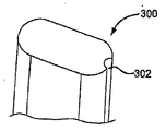
도 3a 내지 도 3c는 권취 지그의 구성 요소의 도면.
도 4a는 권취 지그의 측면도.
도 4b는 권취 지그의 평면도.
도 5a는 팽창된 덮여진 밀봉 장치의 측면도.
도 5b는 팽창된 부분적으로 덮여진 밀봉 장치의 측면도.
도 6은 밀봉 장치의 자기 중심 설정 실시예의 측면도.
도 7은 전개된 밀봉 장치의 측면도.
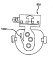
도 8은 전개 핸들 및 부착된 밀봉 장치를 포함하는 전달 시스템의 사시도.
도 9a 내지 도 9d는 전달 시스템의 작동을 설명하는 흐름도.
도 10은 밀봉 장치 전개 핸들의 사시도.
도 11은 밀봉 장치 전개 핸들의 조립체의 사시도.
도 12a는 제1 선형 액추에이터의 실시예의 위에서 본 도면.
도 12b는 제1 선형 액추에이터의 실시예의 측면도.
도 12c는 제1 선형 액추에이터의 실시예의 측면도.
도 12d는 제1 선형 액추에이터의 실시예의 측면도.
도 13a는 잠금 해제 액추에이터의 실시예의 사시도.
도 13b는 작동 위치에서 잠금 해제 액추에이터의 실시예의 사시도.
도 14a는 스프링의 실시예의 사시도.
도 14b는 제1 선형 액추에이터의 단부도.
도 15는 성형된 스프링 구성 요소를 갖는 제1 선형 액추에이터의 실시예의 단부도.
도 16은 스프링 구성 요소의 사시도.1 is a perspective view of the deployed sealing device attached to the distal end of the delivery system.
2a shows an expanded frame of the sealing device.
2B is an end view of the eyelet of the sealing device.
2C is an end view of the frame of the sealing device.
3a to 3c are views of the components of the winding jig.
4A is a side view of the winding jig.
4B is a plan view of the winding jig.
5A is a side view of the inflated covered sealing device.
5B is a side view of the expanded partially covered sealing device.
6 is a side view of a self centering embodiment of a sealing device.
7 is a side view of the deployed sealing device.
8 is a perspective view of a delivery system including a deployment handle and an attached sealing device.
9A-9D are flow charts describing the operation of the delivery system.
10 is a perspective view of the sealing device deployment handle.
11 is a perspective view of an assembly of the sealing device deployment handle.
12A is a top view of an embodiment of a first linear actuator.
12B is a side view of an embodiment of a first linear actuator.
12C is a side view of an embodiment of a first linear actuator.
12D is a side view of an embodiment of a first linear actuator.
13A is a perspective view of an embodiment of an unlocking actuator.
13B is a perspective view of an embodiment of the unlocking actuator in the operating position.
14A is a perspective view of an embodiment of a spring.
14B is an end view of the first linear actuator.
15 is an end view of an embodiment of a first linear actuator having molded spring components.
16 is a perspective view of a spring component.
제1 실시예는 프레임의 근위 단부로부터 원위 단부로 연장되는 복수의 와이어로부터 형성된 팽창 가능한 프레임, 근위 아일릿 및 원위 아일릿을 형성하는 와이어 및 팽창 가능한 와이어 프레임을 적어도 부분적으로 캡슐화하는 밀봉 부재를 갖는 밀봉 장치를 제공한다.The first embodiment is a sealing device having an inflatable frame formed from a plurality of wires extending from the proximal end to the distal end of the frame, the wires forming the proximal eyelet and distal eyelet and a sealing member at least partially encapsulating the inflatable wire frame. To provide.
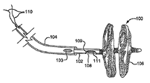
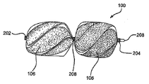
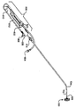
도 1은 밀봉 장치(100)의 일 실시예를 도시하고 있다. 밀봉 장치(100)는 이하의 섹션에서 상세히 설명될 것이다. 밀봉 장치(100)는 제3 튜브(104) 내에 수용될 수 있다. 제3 튜브(104)는 밀봉 장치(100), 제1 튜브(102), 제2 튜브(108), 회수 코드(110) 및 잠금 루프(111)를 포함한다. 제3 튜브(104)는 페박스(Pebax)![]()
![]()
도 1에는 제1 튜브(102)가 또한 도시되어 있다. 전술한 바와 같이, 제1 튜브(102)는 제3 튜브(104) 내에 수용될 수 있다. 제1 튜브(102)는 임의의 외경 크기를 가질 수 있지만, 바람직하게는 제3 튜브(104)의 루멘 내에 끼워지도록 치수 설정된다. 제1 튜브(102)는 페박스![]()
![]()
제1 튜브(102)는 제2 튜브(108)를 수용할 수 있다. 제2 튜브(108)는 본질적으로 타원형 단면을 갖는 관형이고, 제1 튜브(102) 내에 끼워지기에 적합한 외경을 가질 수 있다. 적합한 외경 범위는 약 1.27×0.68 mm일 수 있고, 원위 단부에서 플레어(flare)될 수 있다. 제2 튜브(108)는 폴리머 또는 금속을 포함하는 임의의 적합한 생체 적합성 재료로부터 제조될 수 있다. 바람직한 재료는 PEEK(폴리에테르에테르케톤)일 수 있다. 제2 튜브(108)는 결손 부위로의 밀봉 장치(100)의 전달 및 전개를 보조하는 데 사용될 수 있다. 제2 튜브(108)는 밀봉 장치(100)의 아일릿을 통해 나사 결합되어 밀봉 장치(100)를 전달 시스템 상에 유지하고 밀봉 장치(100)가 전개되는 동안 안정성을 제공한다. 밀봉 장치 아일릿이 더 설명될 것이다.The
회수 코드(110)는 제1 튜브(102)의 더 소형의 루멘 중 2개를 통해 그리고 밀봉 장치(100)의 근위 아일릿을 통해 루프 형성되어, 일단 밀봉 장치가 전개되면 전달 시스템으로의 부착 및 회수 방법을 제공한다. 회수 코드(110)는 밀봉 장치(100)를 전개하기 위해 사용된 핸들에서 종료하는 단부를 갖고 제1 튜브(102)의 길이를 통해 연장된다. 회수 코드(110)는 충분한 강도 및 크기의 임의의 생체 적합성 재료로 제조될 수 있다. 바람직한 재료는 ePTFE(팽창형 폴리테트라플루오로에틸렌)이다.The
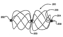
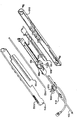
도 2a에 도시되어 있는 바와 같이, 밀봉 장치(100)는 와이어 프레임(200)으로 형성된다. 전달을 위해 위치될 때, 와이어 프레임(200)은, 제2 튜브(108) 상의 위치로서 제3 튜브(104) 내의 연장된 위치에 있다. 와이어 프레임(200)은 용례에 적합한 임의의 크기를 가질 수 있지만, 바람직하게는 15, 20, 25 또는 30 mm의 완성된 외경으로 치수 설정된다. 와이어 프레임(200)은 연속적인 와이어로 형성된다. 임의의 수의 와이어가 와이어 프레임(200)을 구성하기 위해 사용될 수 있다. 와이어의 바람직한 수는 5개이다. 와이어 프레임(200)은, 와이어 프레임(200)이 카테터 기반 전달 또는 흉강경 전달을 위해 접혀질 수 있게 하고 일단 결손부에 위치되면 "기억" 유도된 구성으로 자기 팽창할 수 있게 하는, 탄성 특성을 갖는 와이어로 구성될 수 있다. 탄성 와이어는 스프링 와이어 또는 형상 기억 NiTi(니티놀) 합금 와이어 또는 초탄성 NiTi 합금 와이어일 수 있다. 탄성 와이어는 또한 코어에 상이한 금속을 포함하는 인발 충전형 NiTi일 수 있다. 바람직하게는, 와이어 프레임(200)은 중심에 방사선 불투과성 금속을 포함하는 인발 충전형 NiTi 와이어로 구성될 수 있다. 전개시에, 와이어 구조체는 영구 변형 없이 그 전개된 형상을 취한다.As shown in FIG. 2A, the
와이어 프레임(200) 및 도시되어 있는 다른 와이어 프레임은 0.12 내지 0.4 mm의 외경을 갖는 탄성 와이어 재료로부터 형성된다. 바람직한 실시예에서, 와이어 외경 크기는 약 0.3 mm일 수 있다. 형성될 때, 와이어 프레임(200)은 원위 범퍼(208), 원위 아일릿(204), 잠금 루프(206), 선택적 중심 아일릿(203) 및 근위 아일릿(202)을 포함한다. 도 2b는 와이어 프레임(200)의 아일릿(202, 203, 204)의 형성 중의 탄성 와이어의 위치를 도시하고 있다.
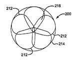
도 2c는 와이어 프레임(200)이 전개될 때 형성되는 디스크를 도시하고 있다. 와이어 프레임(200)을 형성하는 탄성 와이어는 전개 중에 페탈(petal)(212)을 형성한다. 와이어 프레임(200)의 사전 설정된 탄성 와이어 구성은 전개 중에 프레임이 비틀리게 할 수 있다. 이 비틀림은 페탈(212)을 형성한다. 전개된 페탈(212)은 와이어 프레임(200)의 외경(214)을 형성한다. 전개된 페탈(212)은, 밀봉 부재(106)로 덮여질 때, 이하에 설명될 근위 디스크 및 원위 디스크를 형성한다. 페탈(212)은 밀봉 품질을 향상시키기 위해 중첩 구역(216)을 갖도록 최적으로 형성된다. 페탈(212)의 반경은, 탄성 와이어의 첨예한 굽힘각을 최소화하도록, 그리고 장치의 밀봉 품질을 향상시키고 와이어의 굽힘 피로를 감소시키고 장치 적재력(loading force)을 감소시키는 것을 보조하는 것인 페탈(212)의 지지되지 않은 섹션을 최소화하도록 최대화될 수 있다. 전개된 페탈(212)은 중심 아일릿(203)의 일 측면에서 디스크를 형성한다. 전개된 구성이 더 설명될 것이다.2C illustrates a disk formed when the
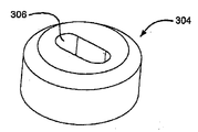
와이어 프레임(200)의 구성은, 자동 와이어 인장을 수반하는 기계 권취 또는 구성 중에 각각의 와이어로부터 현수되는 무게추를 이용한 수동 권취를 포함하는 다양한 수단에 의해 성취될 수 있다. 도 3a 내지 도 3c에는 와이어 프레임(200)의 구성을 보조하는 데 사용될 수 있는 키 형성된 중심핀(300) 및 버튼(304)이 도시되어 있다. 당 기술 분야의 숙련자는 제조 보조부 또는 공구로서 사용하기에 적합한 다수의 재료가 존재한다는 것을 인식할 수 있을 것이다. 중심핀(300)을 형성하는 데 사용하기 위한 바람직한 재료는 코발트 고강도강일 수 있다. 버튼(304) 및 권취 지그를 형성하는 데 사용하기 위한 바람직한 재료는 내부식성 공구강일 것이다. 권취 지그가 더 설명될 것이다. 도 3a에 상세히 도시되어 있는 키 형성된 중심핀(300)은 장치 구성 중에 탄성 와이어를 고정하는 데 사용될 수 있는 홈(302)을 가질 수 있다. 키 형성된 중심핀(300)은 버튼(304) 내의 개구(306)를 통해 탄성 와이어를 안내하는 데 사용될 수 있고, 그 특징이 도 3b 및 도 3c에 도시되어 있다. 버튼(304)은 바람직하게는 권취 지그 내에 단단히 끼워지도록 저부의 오목부(308)를 갖도록 형성된다. 홈(302) 내에 유지되고 버튼(304)의 개구(306)를 통해 삽입된 탄성 와이어는, 범퍼(208) 및 잠금 루프(206)를 형성할 수 있다. 키 형성된 중심핀(300)은 또한 아일릿(202, 203, 및 204)의 형성에 사용된다. 장치 구성 중에, 범퍼(208)의 형성 후에, 탄성 와이어는 키 형성된 중심핀(300) 주위에 권취되어 원위 아일릿(202)을 형성할 수 있다. 다른 아일릿(203, 204)이 유사한 방식으로 형성될 수 있다. 일단 키 형성된 중심핀(300)이 버튼(304)에 삽입되면, 탄성 와이어가 권취 지그 내의 홈 내에 삽입될 수 있다.The configuration of the
권취 지그는 밀봉 장치(100)의 구성 및 가공 중에 탄성 와이어를 고정하고 형성하는 데 사용될 수 있다. 통상의 권취 지그는 당 기술 분야에 통상적으로 공지된 바와 같이 구성될 수 있다. 이러한 권취 지그의 구성을 위해 사용되는 재료는 전술되어 있다. 바람직한 권취 지그가 도 4a 및 도 4b에 도시되어 있다. 도 4a는 권취 지그(400)의 측면도를 도시하고 있다. 도 4b는 바람직한 권취 지그(400)의 상부의 도면을 도시하고 있다. 권취 지그(400)는 장치 구성 중에 키 형성된 중심핀(300) 및 버튼(304)을 유지하도록 형성되고 치수 설정될 수 있는 구멍(402)을 포함한다. 지그 표면 내의 홈(404)은, 페탈(212) 내에 탄성 와이어를 고정하고 형성하는 데 사용된다. 홈(404)은 임의의 직경을 가질 수 있지만 탄성 와이어의 외경을 수용하도록 바람직하게 치수 설정된다. 도 5a에 도시되어 있는 일 실시예에서, 권취 지그 조립체는 중심 아일릿(203), 페탈 조립체 및 근위 아일릿(204)을 형성하는데 사용될 수 있다. 성형된 와이어는 권취 지그 조립체 내에 구속되고, 가열되고, 당 기술 분야에 통상적으로 공지된 바와 같이 설정된 형상으로 가공될 수 있다.The winding jig can be used to fix and form the elastic wire during the construction and processing of the
도 5a는 와이어 프레임(200)과 밀봉 부재(106)의 복합 조립체인 밀봉 장치(100)의 실시예를 도시하고 있다. 밀봉 부재(106)는 접합제에 의해 와이어 프레임(200)에 부착될 수 있다. 와이어 프레임(200)은, 예를 들어 플루오르화 에틸렌 프로필렌(FEP) 또는 다른 적합한 접착제와 같은 접합제로 코팅될 수 있다. 접착제는 접촉 코팅, 분말 코팅, 침지 코팅, 스프레이 코팅 또는 임의의 다른 적절한 수단을 통해 도포될 수 있다. 바람직한 실시예에서, FEP 접착제는 정전 분말 코팅에 의해 도포된다. 밀봉 부재(106)는 다크론(DACRON)![]()
![]()
도 5a에는 밀봉 부재(106)로 각각 덮여져 있고 필름으로 감겨져 있는 근위 아일릿(202), 원위 아일릿(204) 및 중심 아일릿(203)이 또한 도시되어 있다. 아일릿(202, 203, 204)은 장치에 대한 밀봉 부재(106)의 접착을 조장하기 위해 필름으로 감겨져 있을 수 있다. 아일릿(202, 203, 204)을 감는 데 사용된 필름은 임의의 생체 적합성인 얇은 재료일 수 있지만, 비다공성 FEP의 하나 이상의 층으로 적층될 수 있는 얇은 다공성 ePTFE의 다수의 층으로 바람직하게 구성되는 재료이다.Also shown in FIG. 5A is a
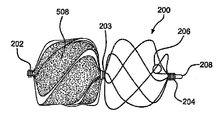
도 5b는 와이어 프레임(200)을 부분적으로 덮고 있는 밀봉 부재(508)를 포함하는 밀봉 장치(100)의 실시예를 도시하고 있다. 부분적으로 덮인 장치는 밀봉 부재(508)로 부분적으로 또는 완전히 덮여진 원위 벌브(bulb) 또는 근위 벌브를 가질 수 있다.5B shows an embodiment of a
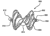
장치의 다른 실시예는 자기 중심 설정 장치(600)이다. 도 6에 도시되어 있는 자기 중심 설정 장치(600)는 와이어 프레임(200)의 것과 유사한 와이어 프레임(602)을 포함한다. 자기 중심 설정 장치(600)는 와이어 프레임(602)과 밀봉 부재(604)의 복합 조립체이다. 와이어 프레임(602)은 와이어 프레임(200)과 동일한 기술 및 재료로 구성될 수 있지만 중심 아일릿을 갖지 않는다. 와이어 프레임(602)은 원위 범퍼(606), 덮여진 원위 아일릿(608), 덮여진 근위 아일릿(610) 및 잠금 루프(612)를 포함한다. 와이어 프레임(602)의 사전 설정된 탄성 와이어 구성은, 프레임이 전개 시에 비틀릴 수 있게 하고 전개 중에 장치(600)의 중심 설정 영역(614)을 생성할 수 있게 한다. 전개 중에, 영역(614)은 결손부 내에 자체로 중심 설정되어 영역(614)과 결손부의 일 측면에 페탈로 구성된 디스크를 형성할 수 있다.Another embodiment of the device is a
도 7은 완전 전개된 밀봉 장치(100)를 도시하고 있다. 전개 중에, 제3 튜브(104)의 구속은 장치(100)로부터 제거되고, 장치는 그 사전 설정된 형상으로 복귀한다. 전개 및 잠금 중에, 잠금 루프(111)는 제1 튜브(102)의 구속으로부터 해제되고 그 사전 설정된 형상으로 복귀하여 근위 아일릿(202)으로부터 비틀린다. 이 방식으로, 장치가 전개된 상태로 잠기게 된다. 도 7은 또한 근위 아일릿(202), 중심 아일릿(203) 및 원위 아일릿(204) 각각에 관련하는 근위 디스크 및 원위 디스크, 요소(702, 704)의 위치를 도시하고 있다.7 shows a fully deployed sealing
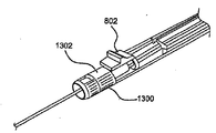
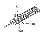
도 8은 제1 튜브(102), 제3 튜브(104) 및 밀봉 장치(100)를 전개하기 위한 핸들을 포함하는 전달 시스템에 부착된 밀봉 장치(100)의 사시도를 도시하고 있다. 도 8은 또한 제1 선형 액추에이터(802), 플러싱 포트(804; flushing port), 제2 선형 액추에이터(806), 잠금 해제 액추에이터(808), 하우징(810) 및 하우징(812) 내의 길이를 갖는 슬롯을 도시하고 있다. 제1 선형 액추에이터(802)는 더 설명될 다양한 구성을 가질 수 있다.FIG. 8 shows a perspective view of a
도 9a 내지 도 9d는 사용 중에 전달 시스템 및 부착된 밀봉 장치(100)의 다양한 구성 요소의 이동을 설명하는 흐름도이다. 밀봉 장치(100)를 사용 전에 전달 시스템 내에 적재하는 것이 도 9a에 설명되어 있다. 전달 시스템 핸들의 구성 요소는 도 8, 도 10 및 도 11에 도시되어 있다. 임상의는 주사기 또는 다른 적합한 기구를 플러싱 포트(804) 상에 부착하고 염수 또는 임의의 다른 적합한 플러싱 재료로 시스템을 충전함으로써 전달 시스템을 플러싱할 수 있다. 제1 선형 액추에이터(802)가 이어서 스프링(1100)에 대해 하우징(810) 내의 슬롯(812) 내에서 이동될 수 있다. 스프링(1100)은 도시되어 있는 바와 같이 구성될 수 있고 또는 판 스프링, 단차형 스프링 또는 당 기술 분야에 통상적으로 공지되어 있는 임의의 형태로서 형성될 수 있다. 이 동작은 도 11에 도시되어 있는 맨드릴 제어 레버(1100)를 하우징(810)의 측면으로 슬라이더 로드(1102)에 대해 회전시킨다. 이 동일한 운동은 치수 설정 인서트(1103) 내의 원위 노치(1104)로부터 자유롭게 제1 선형 액추에이터(802)를 이동시키고, 제2 튜브(108)가 근위측으로 또는 원위측으로 병진 이동하는 것을 방지한다. 치수 설정 인서트(1103)는 적합한 기계적 특성을 갖는 임의의 재료일 수 있다.9A-9D are flow diagrams illustrating the movement of various components of the delivery system and attached sealing
의료용 장치를 전달하는 데 사용되는 통상의 핸들, 핸들 구성 요소, 도구 또는 카테터는, 폴리메틸 메타크릴레이트(PMMA 또는 아크릴), 폴리스티렌(PS), 아크릴로니트릴 부타디엔 스티렌(ABS), 폴리염화비닐(PVC), 변성 폴리에틸렌 테레프탈레이트 글리콜(PETG), 셀룰로오스 아세테이트 부티레이트(CAB)를 포함하는 비정질 범용 열가소성 수지와; 폴리에틸렌(PE), 고밀도 폴리에틸렌(HDPE), 저밀도 폴리에틸렌(LDPE 또는 LLDPE), 폴리프로필렌(PP), 폴리메틸펜텐(PMP)을 포함하는 반결정질 범용 플라스틱과; 폴리카보네이트(PC), 폴리페닐렌 옥사이드(PPO), 변성 폴리페닐렌 옥사이드(ModPPO), 폴리페닐렌 에테르(PPE), 변성 폴리페닐렌 에테르(ModPPE), 열가소성 폴리우레탄(TPU)을 포함하는 비정질 공업용 열가소성 수지와; 폴리아미드(PA 또는 나일론), 폴리옥시메틸렌(POM 또는 아세탈), 폴리에틸렌 테레프탈레이트(PET, 열가소성 폴리에스테르), 폴리부틸렌 테레프탈레이트(PBT, 열가소성 폴리에스테르), 초고분자량 폴리에틸렌(UHMW-PE)을 포함하는 반결정질 공업용 열가소성 수지와; 폴리이미드(PI, 이미드화 플라스틱), 폴리아미드 이미드(PAI, 이미드화 플라스틱), 폴리벤지미다졸(PBI, 이미드화 플라스틱)을 포함하는 고성능 열가소성 수지와; 폴리설폰(PSU), 폴리에테르이미드(PEI), 폴리에테르 설폰(PES), 폴리아릴 설폰(PAS)을 포함하는 비정질 고성능 열가소성 수지와; 폴리페닐렌 설파이드(PPS), 폴리에테르에테르케톤(PEEK)을 포함하는 반결정질 고성능 열가소성 수지와; 플루오르화 에틸렌 프로필렌(FEP), 에틸렌 클로로트리플루오로에틸렌(ECTFE), 에틸렌, 에틸렌 테트라플루오로에틸렌(ETFE), 폴리클로로트리플루오로에틸렌(PCTFE), 폴리테트라플루오로에틸렌(PTFE), 폴리비닐리덴 플루오라이드(PVDF), 퍼플루오로알콕시(PFA)를 포함하는 반결정질 고성능 열가소성 수지, 즉 플루오로폴리머와 같은 통상적으로 공지된 재료를 포함할 수 있다. 다른 통상적으로 공지된 의료용 등급 재료는 엘라스토머 유기실리콘 폴리머, 폴리에테르 블록 아미드 또는 열가소성 코폴리에테르(PEBAX) 및 스테인레스강 및 니켈/티타늄 합금과 같은 금속을 포함한다.Conventional handles, handle components, tools or catheters used to deliver medical devices include polymethyl methacrylate (PMMA or acrylic), polystyrene (PS), acrylonitrile butadiene styrene (ABS), polyvinyl chloride ( PVC), modified polyethylene terephthalate glycol (PETG), cellulose acetate butyrate (CAB); Semicrystalline general purpose plastics including polyethylene (PE), high density polyethylene (HDPE), low density polyethylene (LDPE or LLDPE), polypropylene (PP), polymethylpentene (PMP); Amorphous including polycarbonate (PC), polyphenylene oxide (PPO), modified polyphenylene oxide (ModPPO), polyphenylene ether (PPE), modified polyphenylene ether (ModPPE), thermoplastic polyurethane (TPU) Industrial thermoplastic resins; Polyamide (PA or nylon), polyoxymethylene (POM or acetal), polyethylene terephthalate (PET, thermoplastic polyester), polybutylene terephthalate (PBT, thermoplastic polyester), ultra high molecular weight polyethylene (UHMW-PE) Semicrystalline industrial thermoplastic resin containing; High performance thermoplastic resins including polyimide (PI, imidized plastic), polyamide imide (PAI, imidized plastic), polybenzimidazole (PBI, imidized plastic); Amorphous high performance thermoplastics including polysulfone (PSU), polyetherimide (PEI), polyether sulfone (PES), polyaryl sulfone (PAS); Semicrystalline high performance thermoplastics including polyphenylene sulfide (PPS), polyetheretherketone (PEEK); Fluorinated Ethylene Propylene (FEP), Ethylene Chlorotrifluoroethylene (ECTFE), Ethylene, Ethylene Tetrafluoroethylene (ETFE), Polychlorotrifluoroethylene (PCTFE), Polytetrafluoroethylene (PTFE), Polyvinyl And commonly known materials such as semi-crystalline high performance thermoplastics, including fluoride (PVDF), perfluoroalkoxy (PFA), ie fluoropolymers. Other commonly known medical grade materials include elastomeric organosilicon polymers, polyether block amides or thermoplastic copolyethers (PEBAX) and metals such as stainless steel and nickel / titanium alloys.
치수 설정 인서트(1103)의 원위 노치(1104) 및 근위 노치(1106)는 하우징 슬롯(812)의 제1 선형 액추에이터(802)의 위치설정을 보조하는 데 사용될 수 있다. 2개의 노치(1104, 1106) 각각 사이의 거리는, 전달 시스템 상에 적재되기 전에 제2 튜브(108) 상으로 신장될 때 밀봉 장치(100)의 길이일 수 있다. 치수 설정 인서트(1103)는 다양한 장치 길이를 수용하도록 치수 설정될 수 있고, 바람직하게는 약 6.25 내지 13.32 cm인 근위 노치(1106)의 근위 단부와 원위 노치(1104)의 근위 단부 사이의 거리를 갖고, 약 22.28 cm 길이이다. 노치(1104, 1106)는 임의의 형상일 수 있지만, 바람직하게는 직사각형이다.The
제1 선형 액추에이터(802)는 이어서 하우징(810)의 근위 단부를 향해 슬롯(812) 내의 중간점으로 이동한다. 이 동작은, 제1 튜브(102)가 근위측으로 이동할 수 있게 하고 밀봉 장치(100) 근위 단부가 근위측으로 이동할 수 있게 하여, 따라서 밀봉 장치(100)를 신장시킨다. 제1 선형 액추에이터(802)는 임의의 형상(레버, 볼)일 수 있지만, 바람직하게는 임상의의 엄지손가락을 수용하도록 성형된다. 제1 선형 액추에이터(802)는 적합한 기계적 특성을 갖는 임의의 재료로 구성될 수 있지만, 바람직하게는 치수 설정 인서트(1103)의 것과 유사한 재료이다. 제1 선형 액추에이터(802)의 특징은, 회수 코드(110)를 고정하기 위해 제1 선형 액추에이터(802)의 상부 부분에 형성된 것인 리세스 형성된 치형부이다. 이 특징은 바람직하지만 선택적이다. 치형부는 임의의 구불구불한 경로로 형성될 수 있고 또는 밀봉 장치(100)의 적재, 전개 또는 회수 중에 회수 코드(110)에 대한 저항을 생성하도록 요구되는 임의의 형상을 가질 수도 있다. 대응 돌출 치형부(도시 생략)가 회수 코드 잠금부(803)의 저부면에 형성될 수 있다. 이들 치형부는 함께 끼워질 수 있고 회수 코드를 견고하게 유지할 수 있다. 소직경 코드를 고정하기 위한, 당 기술 분야에 통상적으로 공지되어 있는 다른 방법이 또한 사용될 수 있고, 이하의 섹션에서 상세히 설명될 것이다.The first
제1 선형 액추에이터(802)는 이어서 장치가 제3 튜브(104) 내에 적재될 때까지 근위측으로 더 이동된다. 이 동작 중에, 스프링(1100)은 제1 선형 액추에이터(802) 및 맨드릴 제어 레버(1000)를 슬롯(812)의 좌측으로 그리고 치수 설정 인서트(1103)의 근위 노치(1106) 내로 압박한다. 제2 튜브(108)는 밀봉 장치(100) 및 제1 튜브(102)와 함께 근위측으로 자유롭게 이동한다. 제1 선형 액추에이터(802)가 근위측으로 이동함에 따라, 제2 튜브(108), 밀봉 장치(100) 및 제1 튜브(102)가 제3 튜브(104) 내로 활주하거나 병진 이동한다. 제1 선형 액추에이터(802)가 그 최근위측 위치에 있게 된 후에, 시스템은 재차 전술한 방식으로 염수를 플러싱할 수 있다.The first
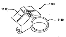
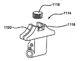
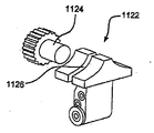
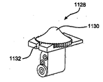
제1 선형 액추에이터(802)의 대안적인 실시예가 도 12a 내지 도 12d에 도시되어 있다. 도 12a는 잠금된 회수 코드 위치에서 대안적인 선형 액추에이터(1108)의 사시도를 도시하고 있다. 선형 액추에이터(1108)는 선형 액추에이터(802)와 구성이 유사하지만, 회수 코드 잠금링(1110) 및 회수 코드 홈(1112)을 특징으로 한다. 도 12b는 용이한 조작을 용이하게 하기 위해 선형 액추에이터의 측면을 지나 연장되는 썸휠(1116)을 갖도록 구성되는 대안적인 실시예(1114)를 도시하고 있다. 썸휠(1116)은 회수 코드가 그 주위에 권취되는 나사산 형성 포스트(1118) 상에 나사 결합된다. 실시예(1114)는 회수 코드가 나사산 형성 포스트(1118) 주위에 이를 고정하기 전에 그를 통해 안내되는 회수 코드 홈(1120)을 또한 포함한다. 도 12c는, 회수 코드가 그 주위에 권취되고 액추에이터(1122)의 측면의 나사산 형성 구멍(도시 생략) 내로 나사산 형성 포스트(1124)를 삽입하는 동작에 의해 액추에이터(1122)에 고정되는 것인 측면 장착된 나사산 형성 썸휠(1124)을 이용하는 또 다른 실시예(1122)를 도시하고 있다. 나사산 형성 포스트(1124) 주위에 회수 코드를 나사 결합하기 전에, 회수 코드는 회수 코드 홈(1126)을 통해 삽입된다. 또 다른 실시예(1128)가 도 12d에 도시되어 있다. 실시예(1128)는 성형된 썸휠(1130)을 갖는 선형 액추에이터를 도시하고 있다. 썸휠(1130)은 선형 액추에이터의 에지를 약간 지나 연장되어 선형 액추에이터의 조작을 용이하게 한다. 회수 코드는 코드 홈(1132)을 통해 삽입되고 나사산 형성 포스트(도시 생략) 주위에 권취된다. 성형된 썸휠(1130)이 이어서 나사산 형성 포스트 상에 고정되어 회수 코드를 고정시킨다.An alternative embodiment of the first
결손부 내로의 밀봉 장치(100)의 전개가 도 9b에 설명되어 있다. 제1 선형 액추에이터(802)는 정지부에 도달할 때까지 원위측으로 이동한다. 이 이동은 제1 튜브(102) 및 제2 튜브(108)가 제3 튜브(104) 내에서 원위측으로 이동할 수 있게 한다. 선형 액추에이터(802)는 이어서 스프링(1100)에 대해 슬롯(812) 내에서 우측으로 이동되어야 한다. 선형 액추에이터(802)가 우측으로 이동될 때, 맨드릴 제어 레버(1000)가 슬라이더 로드(1102) 상에서 회전된다. 이 동작은 치수 설정 인서트(1103) 내의 근위 노치(1106)로부터 선형 액추에이터(802)가 자유로워지게 할 수 있다. 이 동작 후에, 선형 액추에이터(802)는 원위측으로 더 병진 이동된다. 이는 밀봉 장치(100)의 제1 튜브(102) 및 근위 아일릿(202)이 원위측으로 이동할 수 있게 한다. 또한, 이 동작에 의해 영향을 받는 것은, 이동이 방지되는 밀봉 장치(100)의 원위 단부이다. 제1 튜브(102)는 결손부 내에서 장치를 전개하기 위해 제3 튜브로부터 장치를 안내한다. 선형 액추에이터(802)를 슬롯(812)의 단부로 원위측으로 이동시키는 것은, 전체 밀봉 장치가 전개되도록 한다. 당 기술 분야의 숙련자는, 전술한 단계들이 밀봉 장치(100)의 최적의 위치설정을 허용하기 위해 특정 지점에서 정지되고 역전될 수 있다는 것을 인식할 수 있을 것이다.The development of the
장치를 잠그는 것은 도 9c에 도시되어 있는 흐름도에 설명되어 있다. 회수 코드 잠금부(803)가 제1 선형 액추에이터(802)로부터 스냅 고정 해제될 수 있다. 임상의는 부착된 잠금 해제 액추에이터(808)를 파지함으로써 제2 선형 액추에이터(806)를 파지할 수 있고 이를 하우징(810)의 중간을 향해 누를 수 있다. 제2 선형 액추에이터(806)는 임의의 크기 또는 형상일 수 있지만, 바람직하게는 하우징(810)의 종방향 표면의 슬롯(1002) 내에 끼워지도록 치수 설정된다. 선형 액추에이터(806)는 스냅 끼워맞춤에 의해 잠금 해제 액추에이터(808)와 끼워진다. 아교 또는 성형된 부분으로서의 구성과 같은 임의의 부착 수단은 선형 액추에이터(806)에 잠금 해제 액추에이터(808)를 체결하기에 충분할 것이다. 제2 선형 액추에이터(806) 및 잠금 해제 액추에이터(808) 양자 모두에 대해 적절한 재료는 적합한 기계적 특성의 임의의 재료일 수 있지만, 바람직하게는 전술한 핸들 구성 요소의 것과 유사하다. 잠금 해제 액추에이터(808)는 사용자가 장치를 확실하게 파지할 수 있게 하도록 구성된다. 파지는, 잠금 해제 액추에이터(808)의 측면 상의 돌출부에 의해 보조될 수 있다. 이들 돌출부는 잠금 해제 액추에이터(808)의 것과 유사한 재료로 제조될 수 있고 또는 높은 마찰계수를 갖는 재료 또는 잠금 해제 액추에이터(808)의 것보다 유연한 재료로 제조될 수 있다. 이들 돌출부는 장치의 파지를 더 보조하기 위해 앞서 열거된 재료와 함께 표면 내에 격자, 조면화(roughening), 융기된 디자인 또는 줄무늬를 갖고 또한 형성될 수 있다. 잠금 해제 액추에이터(808)의 표면 상의 이들 특징부는 또한 파지용 돌출부의 사용 없이 파지를 보조하는 데 사용될 수 있고, 제2 선형 액추에이터(806)의 측방향 표면에 직접 적용될 수도 있다. 슬롯(1002)은, 밀봉 장치의 잠금 해제까지 최원위 위치에 제2 선형 액추에이터(806)를 유지하기 위해 정지부를 갖도록 구성될 수 있다. 바람직한 정지부는 주름진 영역의 형태로 도 10 및 도 11에 도시되어 있지만, 또한 임의의 방식의 기계적 정지부일 수도 있다. 슬롯(1002)은 임의의 길이를 가질 수 있지만, 바람직하게는 제2 선형 액추에이터(806)의 폭에 약 3.18 cm를 더한 값으로 근위측으로 병진 운동하기에 충분한 길이를 갖는다. 슬롯(1002)은 제2 선형 액추에이터(806)를 수용할 수 있는 임의의 형상일 수 있다.Locking the device is described in the flow chart shown in FIG. 9C. The
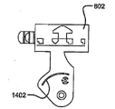
제2 선형 액추에이터(806)의 대안적인 실시예가 도 13a 및 도 13b에 도시되어 있다. 잠금 해제 액추에이터(808)를 파지하고 제2 선형 액추에이터(806)를 작동시키는 대신에, 회전 가능한 잠금 해제 액추에이터(1300)가 파지되고 회전되어 잠금 해제에 영향을 준다. 회전 가능한 잠금 해제 액추에이터(1300)는 제1 선형 액추에이터(802)의 전방 이동을 방지할 수 있는 윈도우(1302)를 포함할 수 있다. 잠금 해제 액추에이터(1300)는, 회전 시에, 도 10에 도시되어 있는 잠금 해제 액추에이터(806)와 동일한 동작을 허용한다.An alternative embodiment of the second
일단 제2 선형 액추에이터(808)가 파지되면, 임상의는 제2 선형 액추에이터(806)를 근위측으로 이동시킬 수 있다. 이 동작은 제3 튜브(104), 맨드릴 제어 레버(1000), 치수 설정 인서트(1103) 및 제2 튜브(108)의 근위측 이동을 초래한다. 제2 튜브(108)는 장치의 아일릿들 사이로부터 근위측으로 이동한다. 이 동작을 성취하는 대안적인 방법은, 제2 선형 액추에이터(806) 대신에 핸들의 원위 단부에 비틀림 메커니즘을 제공하는 것일 수 있다. 이 비틀림 메커니즘에는 제2 선형 액추에이터(806)와 동일한 제3 튜브(104), 맨드릴 제어 레버(1000), 치수 설정 인서트(1103) 및 제2 튜브(108)의 운동을 허용하는 슬롯이 마련될 수 있다.Once the second
일단 잠금 해제가 성취되면, 회수 코드 잠금부(803)는 이어서 제1 선형 액추에이터(802)로부터 이를 제거하도록 비틀리고, 회수 코드(110)가 전달 시스템으로부터 자유로워질 때까지 잡아당겨진다. 회수 코드(110)는 일 단부에서 회수 코드 잠금부(803)에 부착된다. 회수 코드(110)는 케블라(Kevlar)![]()
![]()
회수 코드 잠금부(803)를 구성하기에 적합한 재료는 하우징(810) 및 다른 핸들 구성 요소를 구성하는 데 사용된 것과 유사하다. 전술한 바와 같이, 회수 코드 잠금부(803)는 바람직하게는 회수 코드(110)를 파지하려는 목적으로 선형 액추에이터(802) 내의 오목부에 대응하는 치형부 또는 돌출부를 갖는다. 회수 코드 잠금부(803)는 회수 코드(110)가 고정될 수 있게 하기 위해 다양한 형상으로 구성될 수 있다. 바람직한 구성은, 회수 코드(110)가 그를 통해 나사 결합되어 매듭지어질 수 있게 하는 회수 코드 잠금부(803)를 통한 구멍을 포함할 수 있다. 회수 코드 잠금부(803)를 비튼 후에, 이는 회수 코드(110)가 전달 시스템으로부터 제거될 때까지 잡아당겨진다.Suitable materials for constructing the
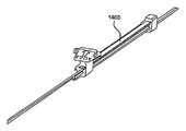
도 9c에 설명되어 있는 단계 4에 앞서, 밀봉 장치(100)는 도 9d에 도시되어 있는 흐름도에 설명된 바와 같이 회수될 수 있다. 회수 코드 잠금부(803)가 제1 선형 액추에이터(802)에 스냅 결합될 수 있다. 이는 회수 코드(110)를 적소에 잠그는 역할을 한다. 임상의는 이어서 슬롯(812)의 우측 에지로 제1 선형 액추에이터(802)를 이동시킨다. 제1 선형 액추에이터(802)는, 맨드릴 제어 레버(1000)가 핸들의 우측으로 슬라이더 로드(1102) 상에서 회전하는 동안 슬롯(812) 상에서 우측으로 이동하여 스프링(1100)을 누른다. 슬라이더 로드(1102)는 바람직하게는 원형 단면을 갖지만, 당 기술 분야의 숙련자는 다양한 단면 형상(예를 들어, 정사각형 또는 삼각형)이 허용 가능할 수 있다는 것을 인식할 수 있을 것이다. 슬라이더 로드(1102)는 또한 도 14a 및 도 14b에 도시되어 있는 바와 같이 크라운 스프링(1400)의 형상으로 구성될 수 있다. 스프링은 선형 액추에이터의 전후방 병진 이동을 허용하기 위해 선형 액추에이터를 통해 슬롯(1402) 내에 삽입될 수 있다. 스프링(1100)의 대안적인 실시예가 도 15에 의해 도시되어 있는 바와 같이 제1 선형 액추에이터(802)의 일체부(1500)로서 스프링 성형될 수 있다. 스프링(1100)의 다른 실시예가 도 16에 도시되어 있다. 이 구성에서, 스프링(1600)은 하우징(810)에 부착되고, 키 위치에서 제1 선형 액추에이터(802) 상에 압박된다. 전술한 바와 같이, 당 기술 분야의 숙련자는 스프링 또는 성형된 부분으로서 사용하기 위해 적절한 재료를 인식할 수 있을 것이다. 제1 선형 액추에이터(802)는 원위 노치(1104)로부터 자유로워지고 제2 튜브(108)는 이동하는 것이 방지된다. 제1 선형 액추에이터는 임상의에 의해 근위측으로 이동되어 제1 튜브(102)가 근위측으로 이동되게 한다. 이 운동은 밀봉 장치(100)의 근위 단부를 병진 이동시켜 장치(100)를 근위측으로 신장시키고 이를 제3 튜브(104) 내로 잡아당겨진다.Prior to step 4 described in FIG. 9C, the
예:Yes:
본 발명의 범주를 한정하려는 의도 없이, 이하의 예는 본 발명의 다양한 실시예가 어떻게 이루어지고 그리고/또는 사용될 수 있는지를 예시한다.Without intending to limit the scope of the invention, the following examples illustrate how various embodiments of the invention can be made and / or used.
예 1:Example 1:
도 1과 유사한 밀봉 장치가 이하의 구성 요소 및 조립 프로세스를 사용하여 제조되었다.A sealing device similar to FIG. 1 was made using the following components and assembly process.
이하의 특성을 갖는 팽창형 폴리테트라플루오로에틸렌 재료가 얻어졌다.Expanded polytetrafluoroethylene materials having the following characteristics were obtained.
1 psi(6.9 kPa)의 메탄올 기포점1 psi (6.9 kPa) methanol bubble point
2.2 g/m2의 질량/면적Mass / area of 2.2 g / m 2
1.6 kg/inch의 종방향 최대 하중Longitudinal maximum load of 1.6 kg / inch
0.0003 인치(0.000762 cm)의 두께Thickness of 0.0003 inches (0.000762 cm)
92000 psi(634.3 MPa)의 종방향 매트릭스 인장 강도.Longitudinal matrix tensile strength of 92000 psi (634.3 MPa).
이하의 시험 방법 및 장비가 전술한 특성을 결정하는 데 사용되었다. 메탄올 기포점은 1 인치(2.54 cm) 직경 푸트, 0.2 psi/초의 상승률 및 메탄올의 액체 매체를 갖는 주문형 제조기를 사용하여 측정되었다. 재료의 길이 및 폭은 금속 자를 사용하여 측정되었다. 질량/면적은 36×5 인치 샘플을 갖는 저울[모델 GF-400 탑 로더 저울, 미국 캘리포니아주 산호세 소재의 에이엔지(ANG)]을 사용하여 측정되었다. 종방향 최대 하중은 10 kg 로드셀(load cell)을 구비하는 재료 시험기[모델 5564, 미국 팬실배니아주 그로브 시티 소재의 인스트론(Instron)]를 사용하여 측정되었다. 게이지 길이는 1 인치(2.54 cm)였고 크로스 헤드 속도는 25 mm/minute였다. 샘플 폭은 1 인치(2.54 cm)였다. 종방향 인장 시험 측정이 재료의 길이 방향에서 취해졌다. 두께는 ¼ 인치의 푸트 직경을 갖는 두께 게이지[미투토요(Mitutoyo) 디지털 지시기 547-400]를 사용하여 측정되었다. 종방향 매트릭스 인장 강도(MTS)는 이하의 식을 사용하여 계산되었다. 밀도는 식, 밀도 = 질량/체적을 사용하여 계산되었다.The following test methods and equipment were used to determine the above characteristics. Methanol bubble points were measured using a custom-made machine with 1 inch (2.54 cm) diameter foot, 0.2 psi / sec rise rate, and a liquid medium of methanol. The length and width of the material were measured using a metal ruler. Mass / area was measured using a scale with a 36 × 5 inch sample (Model GF-400 Top Loader Scale, ANG, San Jose, CA, USA). The longitudinal maximum load was measured using a material tester (Model 5564, Instron, Grove City, PA) with a 10 kg load cell. The gauge length was 1 inch (2.54 cm) and the cross head speed was 25 mm / minute. Sample width was 1 inch (2.54 cm). Longitudinal tensile test measurements were taken in the longitudinal direction of the material. Thickness was measured using a thickness gauge (Mitutoyo digital indicator 547-400) with a foot diameter of ¼ inch. Longitudinal matrix tensile strength (MTS) was calculated using the following formula. Density was calculated using the formula, density = mass / volume.
![]()
![]()
여기서 ρPTFE = 2.2 그램/ccWhere ρPTFE = 2.2 g / cc
σsample = (최대 하중/폭)/두께σ sample = (maximum load / width) / thickness
ρsample = (질량/면적)/두께ρ sample = (mass / area) / thickness
다음의 특성을 갖는 FEP(플루오로화 에틸렌 프로필렌)의 얇은 층을 갖춘 팽창형 폴리테트라플루오로에틸렌이 얻어졌다.Expanded polytetrafluoroethylene was obtained with a thin layer of FEP (Fluorinated Ethylene Propylene) having the following properties.
36.1 g/㎡의 질량/면적Mass / area of 36.1 g / ㎡
12.6 kg/inch의 종방향 최대 하중Longitudinal maximum load of 12.6 kg / inch
0.3 kg/inch의 횡방향 최대 하중Transverse maximum load of 0.3 kg / inch
0.0012 인치의 두께0.0012 inches thick
이하의 시험 방법 및 장비가 전술한 특성을 결정하는 데 사용되었다. 재료는 36×1 인치 샘플의 샘플 면적을 갖는 정밀한 분석 저울[모델 GF-400 탑 로더 저울, 미국 캘리포니아주 산호세 소재의 에이엔지(ANG)]을 사용하여 계량되었다. 재료의 길이 및 폭은 금속 자를 사용하여 측정되었다. 재료 두께는 ¼ 인치의 푸트 직경을 갖는 디지털 두께 게이지[미투토요(Mitutoyo) 디지털 지시기 547-400]를 사용하여 측정되었다. 최대 횡방향 하중이 10 kg 로드셀을 구비하는 재료 시험기[모델 5564, 미국 팬실배니아주 그로브 시티 소재의 인스트론(Instron)]를 사용하여 측정되었다. 샘플 폭은 1 인치(2.54 cm)였고, 게이지 길이는 1 인치(2.54 cm)였고 크로스 헤드 속도는 25 mm/minute였다. 최대 종방향 하중이 200 kg 로드셀을 구비하는 재료 시험기[모델 5564, 미국 팬실배니아주 그로브 시티 소재의 인스트론(Instron)]를 사용하여 측정되었다. 샘플 폭은 1 인치(2.54 cm)였고, 게이지 길이는 1 인치(2.54 cm)였고 크로스 헤드 속도는 25 mm/minute였다. 종방향 인장 시험 측정이 재료의 길이 방향에서 취해졌고, 횡방향 인장 시험 측정이 길이 방향에 직교하는 방향에서 취해졌다.The following test methods and equipment were used to determine the above characteristics. The material was weighed using a precision analytical balance (Model GF-400 Top Loader Scale, ANG, San Jose, CA) with a sample area of 36 × 1 inch samples. The length and width of the material were measured using a metal ruler. Material thickness was measured using a digital thickness gauge (Mitutoyo digital indicator 547-400) with a foot diameter of ¼ inch. Maximum lateral load was measured using a material tester (Model 5564, Instron, Grove City, PA) with a 10 kg load cell. Sample width was 1 inch (2.54 cm), gauge length was 1 inch (2.54 cm) and cross head speed was 25 mm / minute. Maximum longitudinal load was measured using a material tester (Model 5564, Instron, Grove City, PA) with a 200 kg load cell. Sample width was 1 inch (2.54 cm), gauge length was 1 inch (2.54 cm) and cross head speed was 25 mm / minute. Longitudinal tensile test measurements were taken in the longitudinal direction of the material and transverse tensile test measurements were taken in the direction orthogonal to the longitudinal direction.
원위 아일릿은 약 0.23 mm의 직경을 갖는 소정 길이의 10% 플래티늄 인발 충전된 니티놀 와이어[미국 인디애나주 포트 웨인 소재의 포트 웨인 메탈즈(Fort Wayne Metals)]를 먼저 얻음으로써 형성되었다. 이 와이어는 "제1 와이어"라 표기되었다. 제1 와이어의 자유 단부가 그 자체로 포개져서 개방 단부형 루프를 생성하였고 개방 단부형 루프는 버튼 내에 삽입되었다. 버튼은 이어서 키 형성된 중심핀 상에 삽입되었다. 버튼은 키 형성된 중심핀을 수용하기 위한 중심부를 통한 개구를 갖도록 그리고 권취 지그 내에 확실하게 위치될 수 있게 하는 특징부를 갖도록 형성되었다. 키 형성된 중심핀(약 0.51 mm의 장축, 약 0.25 mm의 단축 및 약 10.16 mm의 길이)이 권취 지그의 중심부에 삽입되었다. 키 형성된 중심핀은 고강도 강[수퍼 코발트 HSS 공구 비트, MSC#56424278, 세코 페이거스타(Seco Fagersta)]으로부터 제조되었다. 이 고강도 강은 1시간 동안 1475℉(801.7℃)에서 제조 지침에 따라 템퍼링되었다. 권취 지그 및 버튼은 내부식성 공구강으로부터 하우스(house)에서 제조되었다.The distal eyelets were formed by first obtaining a length of 10% platinum drawn filled nitinol wire (Fort Wayne Metals, Fort Wayne, Indiana) with a diameter of about 0.23 mm. This wire was designated as "first wire." The free end of the first wire was itself folded to create an open end loop and the open end loop was inserted into the button. The button was then inserted onto the keyed center pin. The button was formed to have an opening through the central portion for receiving the keyed center pin and to have a feature that allows it to be securely positioned in the winding jig. A keyed center pin (about 0.51 mm long axis, about 0.25 mm short axis and about 10.16 mm length) was inserted in the center of the winding jig. The keyed center pin was made from high strength steel (super cobalt HSS tool bit, MSC # 56424278, Seco Fagersta). This high strength steel was tempered according to manufacturing instructions at 1475 ° F. (801.7 ° C.) for 1 hour. The winding jig and button were made in a house from corrosion resistant tool steel.
제2 길이의 동일한 유형의 인발 충전된 니티놀 와이어가 얻어졌고 "제5 와이어"로 표기되었다. 제1 와이어, 제5 와이어 및 부가적인 3개의 와이어가 와이어 단부에 중량추를 부착함으로써 인장되었다. 제1 와이어 및 제5 와이어는 이어서 제1 와이어의 자유 단부 주위에 완전 1회전 권취되었다. 3개의 부가적인 와이어가 권취 지그에 도입되었고, 모든 5개의 와이어가 약 1.98 mm의 높이로 제1 와이어의 자유 단부 주위에 권취되었다.The same type of drawn-filled nitinol wire of the second length was obtained and designated "5th wire". The first wire, the fifth wire and an additional three wires were tensioned by attaching a weight to the wire ends. The first wire and the fifth wire were then wound one full revolution around the free end of the first wire. Three additional wires were introduced into the winding jig, and all five wires were wound around the free end of the first wire to a height of about 1.98 mm.
원위 디스크는 이어서, 5개의 와이어를 분리하고 이들을 권취 지그의 원주방향 에지 주위의 반경방향 홈에 고정함으로써 형성되었다. 반경은 15 mm의 치수를 갖고 형성되었다. 각각의 와이어는 원위 디스크의 일 페탈로 형성되었다. 페탈의 곡률의 반경은 와이어 내의 첨예한 굴곡각을 최소화하기 위해 최대화되었다.The distal disk was then formed by separating the five wires and securing them to the radial grooves around the circumferential edges of the winding jig. The radius was formed with dimensions of 15 mm. Each wire was formed of one petal of the distal disk. The radius of curvature of the petals was maximized to minimize sharp bend angles in the wire.
중심 아일릿은, 와이어를 함께 그룹화하고 제1 와이어의 자유 단부 및 키 형성된 중심핀 주위에 이들을 약 1.98 mm의 높이로 권취함으로써 형성되었다. 와이어는 이어서 분리되었고 권취 지그의 원주방향 에지 주위에서 반경방향 홈 내에 고정되어 15 mm의 반경을 갖는 근위 디스크를 생성하였다.The central eyelets were formed by grouping the wires together and winding them to a height of about 1.98 mm around the free end of the first wire and the keyed center pin. The wire was then separated and secured in a radial groove around the circumferential edge of the winding jig to create a proximal disc with a radius of 15 mm.
근위 아일릿은, 5개의 와이어를 재차 그룹화하고 제1 와이어의 자유 단부 및 키 형성된 중심핀 주위에 이들을 약 1.98 mm의 높이로 권취함으로써 형성되었다. 5개의 와이어는 이어서 분리되고, 와이어의 상부에 스테인레스강 플레이트를 배치하고 플레이트를 나사로 잠금으로써 고정되었다. 제1 와이어의 자유 단부는 이때 약 3.18 mm의 직경을 갖는 스테인레스강 핀 주위에 1회전 권취되고 다른 5개의 와이어에 유사하게 고정되었다.The proximal eyelets were formed by regrouping five wires and winding them to a height of about 1.98 mm around the free end of the first wire and the keyed center pin. The five wires were then separated and secured by placing a stainless steel plate on top of the wire and locking the plate with screws. The free end of the first wire was then wound one turn around a stainless steel pin with a diameter of about 3.18 mm and similarly secured to the other five wires.
밀봉 장치를 갖는 지그는 이때 안정화용 고정구로부터 제거되어 오븐(Blue M SPX 전기 강제 공기 대류 오븐) 내에 배치되었고, 와이어가 당 기술 분야에 통상적으로 공지되어 있는 바와 같이 열적으로 형상 고정되었다. 장치 및 지그는 이어서 급냉(quenching)되었다. 고정된 와이어는 고정 플레이트로부터 해제되었고, 장치가 냉각되어 지그 및 키 형성된 중심핀으로부터 제거되었다. 장치는 이어서 평탄화된 PEEK(폴리에테르에테르 케톤)의 부분 상에 배치되고 원위 아일릿의 외경으로 수동으로 다듬질되었다. 잠금 루프는 완전 1회전을 넘는 지점으로 수동으로 다듬질되었고 근위 아일릿 및 중심 아일릿을 통해 잡아당겨졌다.The jig with the sealing device was then removed from the stabilizing fixture and placed in an oven (Blue M SPX electric forced air convection oven), and the wire was thermally shaped as is commonly known in the art. The apparatus and jig were then quenched. The fixed wire was released from the fixing plate and the device was cooled down and removed from the jig and keyed center pin. The device was then placed on a portion of the flattened PEEK (polyetherether ketone) and manually trimmed to the outer diameter of the distal eyelet. The locking loop was manually trimmed to a point over one full turn and pulled through the proximal and central eyelets.
장치는 PEEK 맨드릴로부터 타원형 단면을 갖는 키 형성된 스테인레스강 프로세스 맨드릴 상으로 압박되었다. 맨드릴은 근위 아일릿과 중심 아일릿 사이에 45° 시계방향 비틀림을 갖고 중심 아일릿과 원위 아일릿 사이에 제2의 45° 시계방향 비틀림을 갖도록 타원형 단면을 갖는 평탄화된 스테인레스강 와이어(미국 인디애나주 포트 웨인 소재의 에프티 포트 웨인 메탈즈)로부터 제조되었다.The apparatus was pressed from a PEEK mandrel onto a keyed stainless steel process mandrel having an elliptical cross section. The mandrel is a flattened stainless steel wire with a 45 ° clockwise twist between the proximal and central eyelets and an elliptical cross section with a second 45 ° clockwise twist between the central eye and the distal eyelet (Fort Wayne, Indiana, USA). FT Fort Wayne Metals.
프로세스 맨드릴 및 장치가 이어서 안정화용 고정구 내에 배치되었고, 이 고정구는 FEP 분말 코팅기[C-30, 미국 코네티컷주 브래드포드 소재의 일렉트로스태틱 테크놀로지 인크(Electrostatic Technology, Inc.)] 내에 배치되어 완전히 코팅될 때까지 처리되었다. 과잉의 FEP 분말은 장치로부터 제거되었다. FEP는 잠금 루프, 프로세스 맨드릴 및 범퍼로부터 진공 청소되었다. 프로세스 맨드릴 및 장치는 이어서 안정화용 고정구로부터 제거되어 오븐 내에 배치되어 당 기술 분야에 공통적으로 공지된 바와 같이 FEP 코팅을 고정하기 위해 베이킹(baking)되었다.The process mandrel and device were then placed in a stabilizing fixture, which was placed in a FEP powder coater [C-30, Electrostatic Technology, Inc., Bradford, Connecticut] and fully coated. Has been processed. Excess FEP powder was removed from the device. FEP was vacuumed from the lock loop, process mandrel and bumper. The process mandrel and apparatus were then removed from the stabilization fixture and placed in an oven to bake to secure the FEP coating as is commonly known in the art.
중공 코어 필름 맨드릴(35.99 mm O.D., 76.2 cm 길이, 스테인레스강)이 얻어졌다. 22.22 mm의 슬릿폭을 갖는 팽창형 폴리테트라플루오로에틸렌 재료가 얻어져서 나선형 랩핑기 상에 적재되었다. 이 랩핑기는 임의의 원하는 각도, 장력 및 속도에서 PTFE(폴리테트라플루오로에틸렌) 재료를 감기 위해 하우스에서 제조되었다. 맨드릴은 랩핑기 상에 적재되었고, 재료가 중공 코어 맨드릴의 원주 주위에 3회 감겨졌다. 재료는 이어서 맨드릴의 길이에 대해 약 8°의 각도에서 맨드릴 주위에 감겨졌다. 감김의 방향은 역전되고 재료가 동일한 각도로 감겨졌다. 제3 층 및 제4 층이 시임 오프셋을 갖고 동일한 방식으로 감겨졌다. 맨드릴은 랩핑기로부터 제거되어 오븐 내에 삽입되어 45분 동안 370℃로 베이킹되었다. 감겨진 맨드릴은 오븐으로부터 제거되어 실온에서 냉각되었다. 최종 PTFE 튜브가 맨드릴로부터 제거되었다.A hollow core film mandrel (35.99 mm O.D., 76.2 cm long, stainless steel) was obtained. Expanded polytetrafluoroethylene material with a slit width of 22.22 mm was obtained and loaded onto the spiral wrapping machine. This lapping machine was made in house to wind PTFE (polytetrafluoroethylene) material at any desired angle, tension and speed. The mandrel was loaded onto the wrapping machine and the material was wound three times around the circumference of the hollow core mandrel. The material was then wound around the mandrel at an angle of about 8 ° to the length of the mandrel. The winding direction was reversed and the material was wound at the same angle. The third and fourth layers were wound in the same way with seam offset. The mandrel was removed from the wrapper and inserted into the oven and baked at 370 ° C. for 45 minutes. The wound mandrel was removed from the oven and cooled at room temperature. The final PTFE tube was removed from the mandrel.
PTFE 튜브는 이어서 약 140 mm로 절단되었고 155 mm의 원하는 길이로 수동으로 신장되었다. PTFE 튜브가 이어서 프레임 상으로 잡아당겨졌다. PTFE 튜브는 이어서 중심 아일릿 상으로 크림핑(crimping) 된 후 원위 아일릿 및 근위 아일릿 상으로 크림핑되었다.The PTFE tube was then cut to about 140 mm and manually stretched to the desired length of 155 mm. The PTFE tube was then pulled onto the frame. The PTFE tube was then crimped onto the central eyelet and then crimped onto the distal and proximal eyelets.
FEP(플루오르화 에틸렌 프로필렌) 재료의 얇은 층을 갖는 팽창형 폴리테트라플루오로에틸렌이 이어서 중심 아일릿으로 시작하여 아일릿 주위에 4회 감겨졌다. 감겨진 아일릿은 납땜 철로 적소에 점착되었다. PTFE 튜브는 이어서 320℃에서 3분 동안 열 고정되었고 근위 아일릿 및 원위 아일릿의 최외측 지점으로 다듬질되었다. 장치는 맨드릴로부터 제거되었다.Expandable polytetrafluoroethylene with a thin layer of FEP (fluorinated ethylene propylene) material was then wound four times around the eyelet, starting with a central eyelet. The wound eyelets were stuck in place with soldering iron. The PTFE tube was then heat set at 320 ° C. for 3 minutes and trimmed to the outermost points of the proximal and distal eyelets. The device was removed from the mandrel.
예 2:Example 2:
도 6과 유사한 밀봉 장치가 이하의 구성 요소 및 조립 프로세스를 사용하여 제조되었다.A sealing device similar to FIG. 6 was manufactured using the following components and assembly process.
예 1에 설명된 것과 유사한 팽창형 폴리테트라플루오로에틸렌 및 FEP(플루오르화 에틸렌 프로필렌)의 얇은 층을 갖는 팽창형 폴리테트라플루오로에틸렌 재료가 얻어졌다.Expanded polytetrafluoroethylene materials having thin layers of expanded polytetrafluoroethylene and FEP (fluorinated ethylene propylene) similar to those described in Example 1 were obtained.
원위 아일릿은 약 0.23 mm의 직경을 갖는 소정 길이의 10% 플래티늄 인발 충전된 니티놀 와이어(미국 인디애나주 포트 웨인 소재의 포트 웨인 메탈즈)를 먼저 얻음으로써 형성되었다. 이 와이어는 "제1 와이어"라 표기되었다. 제1 와이어의 자유 단부가 그 자체로 포개져서 개방 단부형 루프를 생성하였고 개방 단부형 루프는 버튼 내에 삽입되었다. 버튼은 이어서 키 형성된 중심핀 상에 삽입되었다. 버튼은, 키 형성된 중심핀을 수용하기 위해 중심을 통한 개구를 갖도록 그리고 권취 지그 내에 확실하게 위치될 수 있게 하는 특징부를 갖도록 형성되었다. 키 형성된 중심핀(약 5.79 mm의 장축, 약 0.25 mm의 단축 및 약 10.16 mm의 길이)이 권취 지그의 중심부에 삽입되었다. 키 형성된 중심핀은 고강도 강(수퍼 코발트 HSS 공구 비트, MSC#56424278, 세코 페이거스타)으로부터 제조되었다. 권취 지그 및 버튼은 내부식성 공구강으로부터 하우스에서 제조되었다.The distal eyelets were formed by first obtaining a length of 10% platinum drawn filled nitinol wire (Fort Wayne Metals, Fort Wayne, Indiana) with a diameter of about 0.23 mm. This wire was designated as "first wire." The free end of the first wire was itself folded to create an open end loop and the open end loop was inserted into the button. The button was then inserted onto the keyed center pin. The button was formed to have an opening through the center to receive the keyed center pin and to have features that can be reliably positioned within the winding jig. A keyed center pin (about 5.79 mm long axis, about 0.25 mm short axis and about 10.16 mm length) was inserted in the center of the winding jig. The keyed center pin was made from high strength steel (super cobalt HSS tool bit, MSC # 56424278, Seco Fagerstar). The winding jig and button were made in the house from corrosion resistant tool steel.
제2 길이의 동일한 유형의 인발 충전된 니티놀 와이어가 얻어졌고 "제5 와이어"로 표기되었다. 제1 와이어, 제5 와이어 및 부가적인 3개의 와이어가 와이어 단부에 중량추를 부착함으로써 인장되었다. 제1 와이어 및 제5 와이어는 이어서 제1 와이어의 자유 단부 주위에 완전 1회전 권취되었다. 3개의 부가적인 와이어가 권취 지그에 도입되었고, 모든 5개의 와이어가 약 1.98 mm의 높이로 제1 와이어의 자유 단부 주위에 권취되었다.The same type of drawn-filled nitinol wire of the second length was obtained and designated "5th wire". The first wire, the fifth wire and an additional three wires were tensioned by attaching a weight to the wire ends. The first wire and the fifth wire were then wound one full revolution around the free end of the first wire. Three additional wires were introduced into the winding jig, and all five wires were wound around the free end of the first wire to a height of about 1.98 mm.
장치는 이어서, 5개의 와이어를 분리하고 이들을 권취 지그의 원주방향 에지 주위에서 반경방향 홈에 고정함으로써 형성되었다. 반경은 15 mm의 치수로 형성되었다. 각각의 와이어는 권취 지그 주위에 완전한 회전을 형성하였다.The device was then formed by separating the five wires and securing them in radial grooves around the circumferential edge of the winding jig. The radius was formed with dimensions of 15 mm. Each wire made a complete rotation around the winding jig.
근위 아일릿은, 5개의 와이어를 그룹화하고 제1 와이어의 자유 단부 및 키 형성된 중심핀 주위에 이들을 약 1.981 mm의 높이로 권취함으로써 형성되었다. 5개의 와이어는 이어서 분리되고, 와이어의 상부에 스테인레스강 플레이트를 배치하고 플레이트를 나사로 잠금으로써 고정되었다. 제1 와이어의 자유 단부는 약 3.18 mm의 직경을 갖는 스테인레스강 핀 주위에 1회전 권취되고 다른 5개의 와이어에 유사하게 고정되었다.The proximal eyelets were formed by grouping five wires and winding them to a height of about 1.981 mm around the free end of the first wire and the keyed center pin. The five wires were then separated and secured by placing a stainless steel plate on top of the wire and locking the plate with screws. The free end of the first wire was wound one turn around a stainless steel pin with a diameter of about 3.18 mm and similarly secured to the other five wires.
밀봉 장치를 갖는 지그는 안정화용 고정구로부터 제거되어 오븐(Blue M SPX 전기 강제 공기 대류 오븐) 내에 배치되고, 여기서 와이어가 당 기술 분야에 통상적으로 공지되어 있는 바와 같이 열적으로 형상 고정되었다. 장치 및 지그는 이어서 급냉되었다. 고정된 와이어는 고정 플레이트로부터 해제되었고, 이어서 장치가 냉각되어 지그 및 키 형성된 중심핀으로부터 제거되었다. 잠금 루프는 완전 1회전을 넘는 지점으로 수동으로 다듬질되었고 근위 아일릿 및 중심 아일릿을 통해 잡아당겨졌다.The jig with the sealing device was removed from the stabilizing fixture and placed in an oven (Blue M SPX electric forced air convection oven) where the wires were thermally shaped as is commonly known in the art. The apparatus and jig were then quenched. The anchored wire was released from the anchoring plate and the device was then cooled and removed from the jig and keyed center pin. The locking loop was manually trimmed to a point over one full turn and pulled through the proximal and central eyelets.
장치는 PEEK 맨드릴로부터 타원형 단면을 갖는 키 형성된 스테인레스강 이송 맨드릴 상으로 압박되었다. 맨드릴은 타원형 단면을 갖는 평탄화된 스테인레스강 와이어(미국 인디애나주 포트 웨인 소재의 에프티. 웨인 메탈즈)로부터 제조되었다. 장치는 이어서 이송 맨드릴의 일 단부로부터 부분적으로 제거되었다. 제거된 장치 단부는 대략 180° 시계방향으로 비틀리고 이송 맨드릴 상에 재배치되었다. 장치 및 이송 맨드릴은 오븐(Blue M SPX 전기 강제 공기 대류 오븐) 내에 배치되고, 여기서 와이어가 당 기술 분야에 통상적으로 공지되어 있는 바와 같이 열적으로 형상 고정되었다.The device was pressed from a PEEK mandrel onto a keyed stainless steel transfer mandrel having an elliptical cross section. The mandrel was made from a flattened stainless steel wire (F. Wayne Metals, Fort Wayne, Indiana) with an elliptical cross section. The device was then partially removed from one end of the transfer mandrel. The removed device end was twisted approximately 180 ° clockwise and repositioned on the transfer mandrel. The apparatus and conveying mandrel were placed in an oven (Blue M SPX electric forced air convection oven), where the wires were thermally shaped as is commonly known in the art.
이송 맨드릴 및 장치가 이어서 안정화용 고정구 내에 배치되었고, 이 고정구는 FEP 분말 코팅기[C-30, 미국 코네티컷주 브래드포드 소재의 일렉트로스태틱 테크놀로지 인크(Electrostatic Technology, Inc.)] 내에 배치되어 완전히 코팅될 때까지 처리되었다. 과잉의 FEP 분말은 제거되었다. FEP 분말은 잠금 루프, 프로세스 맨드릴 및 범퍼로부터 진공 청소되었다. 이송 맨드릴 및 장치는 이어서 안정화용 고정구로부터 제거되어 오븐 내에 배치되어 당 기술 분야에 공통적으로 공지된 바와 같이 FEP 코팅을 고정하기 위해 베이킹되었다.The transfer mandrel and device were then placed in a stabilizing fixture, which was placed in a FEP powder coater [C-30, Electrostatic Technology, Inc., Bradford, Connecticut] and fully coated. Has been processed. Excess FEP powder was removed. FEP powder was vacuumed from the lock loop, process mandrel and bumper. The transfer mandrel and device were then removed from the stabilizing fixture and placed in an oven and baked to fix the FEP coating as is commonly known in the art.
중공 코어 필름 맨드릴(35.99 mm O.D., 76.2 cm 길이, 스테인레스강)이 얻어졌다. 22.24 mm의 슬릿폭을 갖는 ePTFE 재료가 얻어져서 나선형 랩핑기 상에 적재되었다. 이 랩핑기는 임의의 원하는 각도, 장력 및 속도에서 PTFE 필름을 감기 위해 하우스에서 제조되었다. 맨드릴은 랩핑기 상에 적재되었고, 필름이 중공 코어 맨드릴의 원주 주위에 3회 감겨졌다. ePTFE 재료는 이어서 맨드릴의 길이에 대해 약 8°의 각도에서 맨드릴 주위에 감겨졌다. 감김의 방향은 역전되고 재료가 동일한 각도로 감겨졌다. 제3 층 및 제4 층이 시임 오프셋을 갖고 동일한 방식으로 감겨졌다. 맨드릴은 랩핑기로부터 제거되어 오븐 내에 삽입되어 45분 동안 370℃로 베이킹되었다. 감겨진 맨드릴은 오븐으로부터 제거되어 실온에서 냉각되었다. 최종 ePTFE는 맨드릴로부터 제거되었다.A hollow core film mandrel (35.99 mm O.D., 76.2 cm long, stainless steel) was obtained. An ePTFE material with a slit width of 22.24 mm was obtained and loaded onto the spiral wrapping machine. This lapping machine was made in house to wind PTFE film at any desired angle, tension and speed. The mandrel was loaded onto the wrapping machine and the film was wound three times around the circumference of the hollow core mandrel. The ePTFE material was then wound around the mandrel at an angle of about 8 ° to the length of the mandrel. The winding direction was reversed and the material was wound at the same angle. The third and fourth layers were wound in the same way with seam offset. The mandrel was removed from the wrapper and inserted into the oven and baked at 370 ° C. for 45 minutes. The wound mandrel was removed from the oven and cooled at room temperature. The final ePTFE was removed from the mandrel.
ePTFE 튜브는 이어서 약 140 mm로 절단되었고 155 mm의 원하는 길이로 수동으로 신장되었다. ePTFE 튜브가 이어서 프레임 상으로 잡아당겨졌다. ePTFE 튜브는 이어서 원위 아일릿 및 근위 아일릿 상으로 크림핑되었다. FEP(플루오르화 에틸렌 프로필렌) 재료의 얇은 층을 갖는 ePTFE가 이어서 아일릿 주위에 4회 감겨졌다. 감겨진 아일릿은 납땜 철로 적소에 점착되었다. ePTFE 튜브는 이어서 320℃에서 3분 동안 열 고정되었고 근위 아일릿 및 원위 아일릿의 최외부 지점으로 다듬질되었다. 장치는 이어서 맨드릴로부터 제거되었다.The ePTFE tube was then cut to about 140 mm and manually stretched to the desired length of 155 mm. The ePTFE tube was then pulled onto the frame. The ePTFE tube was then crimped onto distal and proximal eyelets. EPTFE with a thin layer of FEP (fluorinated ethylene propylene) material was then wound four times around the eyelet. The wound eyelets were stuck in place with soldering iron. The ePTFE tube was then heat set at 320 ° C. for 3 minutes and trimmed to the outermost points of the proximal and distal eyelets. The device was then removed from the mandrel.
예 3:Example 3:
도 8과 유사한 핸들 조립체가 이하의 구성 요소 및 조립 프로세스를 사용하여 제조되었다.A handle assembly similar to FIG. 8 was manufactured using the following components and assembly process.
핸들 조립체용 구성 요소는 사출 성형 프로세스를 사용하여 제조되었다. 부품은 러스트란(Lustran)![]()
![]()
![]()
![]()
핸들의 조립을 위해 요구되는 다른 재료는 구매되는 품목이었다. 당 기술 분야에 통상적으로 공지되어 있는 레이업(layup) 프로세스로 형성된 카테터 튜브가, 0.048 mm의 I.D. 및 0.33 mm의 O.D.를 갖고 원위 팁의 단부 부근에 배치된 플래티늄 이리듐 마커 밴드를 갖도록 주문되었다[미국 뉴햄프셔주 재프리 소재의 텔레플렉스 메디컬(Teleflex Medical)]. 카테터 튜브의 주 본체는 PTFE 선형 및 스테인레스강끈(65 PPI)을 갖는 페박스![]()
![]()
![]()
![]()
구성 요소의 나머지는 하우스 창고로부터 공급되거나 하우스에서 제조되었다. 모든 3중 루멘 튜브는 20% 바륨 설페이트를 갖고 페박스![]()
![]()
제1 튜브가 이하의 방식으로 제조되었다. 둥근 루멘을 갖는 하나의 3중 루멘 압출형 튜브가 얻어졌다. 다른 3중 루멘 압출형 튜브가 타원형 단면을 갖는 하나의 루멘으로 얻어졌다. 스테인레스강 가공 맨드릴이 또한 원형(1.52 mm의 O.D.)으로부터 타원형(1.39×0.81 mm의 O.D.)으로 전이하는 단면 형상을 갖고 얻어졌다. 양 압출형 튜브는 맨드릴 상에 적재되었고, 맨드릴은 양 튜브 상의 더 대형의 루멘을 통해 삽입되어 있다. 2개의 소형인 PTFE로 덮인 스테인레스강 와이어가 2개의 압출형 튜브 중 더 소형인 루멘을 통해 삽입되었다. 맨드릴 및 튜브는 RF(무선 주파수) 다이(2.51 mm의 I.D., 4.45 mm의 길이, D2 공구강으로부터 제조됨) 내에 삽입되었다. 2개의 카테터의 접합부가 RF 다이의 중심에 위치되었다. RF 다이 및 맨드릴은 RF 용접기[Hot Shot I, 미국 뉴욕주 스콧츠빌 소재의 아메리썸 인크(Ameritherm Inc.)] 상의 RF 코일의 중간에 배치되었고 당 기술 분야에 통상적으로 공지되어 있는 바와 같이 용접되었다. 성분들이 리플로우될 때, 압력이 압출형 튜브의 각각의 단부에 인가되어 튜브의 접합부를 합병하였다. 다이는 이어서 압축 공기로 분무되어 다이를 냉각하고 페박스![]()
![]()
윤활 코팅이 제2 튜브에 도포될 수 있다. 실리콘 몰드 이형 스프레이[Nix Stix X-9032A, 미국 뉴저지주 린드허스트 소재의 드와이트 프로덕츠, 인크.(Dwight Products, Inc.)]가 제2 튜브의 원위 30cm에 대해 분무될 수 있고 흄 후드(fume hood) 아래에서 분위기 온도 하에서 건조되었다.A lubricating coating can be applied to the second tube. Silicone Mold Release Spray [Nix Stix X-9032A, Dwight Products, Inc., Lyndhurst, NJ] can be sprayed about 30 cm distal to a second tube and a fume hood It was dried under ambient temperature below.
제3 튜브 서브조립체가 이하의 방식으로 제조되었다. 카테터 튜브는 카테터 튜브의 근위 단부로부터 대략 6.35 cm에서 직선형 면도칼로 이등분되었다. 수형 및 암형 인라인 루어 커넥터[미국 뉴욕주 에지우드 소재의 쿼시나(Qosina)]가 얻어지고 3.45 mm의 I.D.로 드릴링되었다. U.V.(자외선) 경화형 접착제(록타이트 3041)가 카테터 튜브의 이등분된 단부에 도포되었고 드릴링된 루어 피팅이 부착되었다. 접착제는 제조 지침에 따라 경화되었고 루어 피팅이 함께 나사 조임되었다.The third tube subassembly was produced in the following manner. The catheter tube was bisected with a straight razor at approximately 6.35 cm from the proximal end of the catheter tube. Male and female inline luer connectors (Qosina, Edgewood, NY) were obtained and drilled to 3.45 mm I.D. U.V. (ultraviolet) curable adhesive (Loctite 3041) was applied to the bisected ends of the catheter tube and attached with drilled luer fittings. The adhesive was cured according to the manufacturing instructions and the luer fittings were screwed together.
제2 선형 액추에이터 서브조립체가 이하의 방식으로 제조되었다. 제2 선형 액추에이터, 플러싱 포트, 플러싱 가스켓 리테이너 및 실리콘 플러싱 가스켓이 얻어졌다. 플러싱 가스켓은 플러싱 가스켓의 u형 부분이 원위측으로 지향하는 상태로 제2 선형 액추에이터의 후방 내에 삽입되었다. 플러싱 가스켓 리테이너는 제2 선형 액추에이터 내부의 상부에 끼워졌다. 가스켓 리테이너를 적소에 유지하기 위해 가스켓 리테이너 주위에 시아노아크릴레이트 아교가 도포되었다. 플러싱 포트는 제2 선형 액추에이터 내의 구멍 내에 배치되었고, U.V. 경화 접착제가 제조 지침에 따라 도포 및 경화되었다.The second linear actuator subassembly was produced in the following manner. A second linear actuator, flushing port, flushing gasket retainer and silicon flushing gasket were obtained. The flushing gasket was inserted into the rear of the second linear actuator with the u-shaped portion of the flushing gasket directed distally. The flushing gasket retainer was fitted to the top inside the second linear actuator. Cyanoacrylate glue was applied around the gasket retainer to hold the gasket retainer in place. The flushing port was placed in a hole in the second linear actuator, and the U.V. Curing adhesive was applied and cured according to the manufacturing instructions.
제1 튜브가 얻어졌고 시아노아크릴레이트가 단부로부터 2.54 cm 밴드 내의 카테터의 원형 I.D. 섹션의 외측에 도포되었다. 카테터는 이어서, 카테터가 제어 셔틀의 후방부와 동일 높이가 될 때까지 제어 셔틀의 원위 단부 내에 삽입되었다. 카테터는, 2개의 소형 루멘이 수평이고 원형 루멘의 상부 부분 상에 있도록 배향되었다. 회수 코드 잠금부는 제어 셔틀 상에 스냅 결합되었다.A first tube was obtained and the cyanoacrylate was circular I.D. of the catheter in a 2.54 cm band from the end. It was applied to the outside of the section. The catheter was then inserted into the distal end of the control shuttle until the catheter was flush with the rear of the control shuttle. The catheter was oriented such that the two small lumens were horizontal and on the upper portion of the circular lumen. The recovery cord lock snapped onto the control shuttle.
제2 튜브 서브조립체가 이하의 방식으로 제조되었다. 0.033 mm 직경의 니티놀 와이어의 4 인치(10.16 cm) 부분이 제2 튜브 압출부 내에 삽입되었다. 와이어 인서트를 갖는 제2 튜브 압출부는 하이포튜브 내에 삽입되었다. 하이포튜브의 원위 단부는 수동으로 3회 크림핑되었다.The second tube subassembly was produced in the following manner. A 4 inch (10.16 cm) portion of a 0.033 mm diameter nitinol wire was inserted into the second tube extrusion. The second tube extrusion with wire insert was inserted into the hypotube. The distal end of the hypotube was manually crimped three times.
제1 튜브의 원위 단부는 맨드릴 제어 레버의 상부를 통해 그리고 맨드릴 제어 레버의 원위 단부 상의 상부 구멍을 통해 나사 결합되었다. 제2 튜브의 원위 단부는 제어 카테터의 근위 단부 내에 나사 결합되었다. 제2 튜브는, 약 4 in(10.16 cm)의 하이포튜브가 제어 카테터의 단부로부터 돌출될 때까지 제1 튜브 내로 압박되었다. 시아노아크릴레이트 접착제가 약 12.7 mm 섹션 상의 하이포튜브의 근위 단부에 도포되었다. 이 섹션은, 맨드릴 제어 레버의 후방부와 동일 높이가 될 때까지 맨드릴 제어 레버의 근위 단부 내의 상부 구멍 내에 삽입되었다. 제1 튜브의 원위 단부는 이어서 제2 선형 액추에이터의 근위 단부 내에 나사 결합되었다. 제2 선형 액추에이터는 제어 카테터 상의 최후방 위치로 이동되었다.The distal end of the first tube was screwed through the top of the mandrel control lever and through the top hole on the distal end of the mandrel control lever. The distal end of the second tube was screwed into the proximal end of the control catheter. The second tube was pressed into the first tube until about 4 in (10.16 cm) of the hypotube protruded from the end of the control catheter. A cyanoacrylate adhesive was applied to the proximal end of the hypotube on about 12.7 mm section. This section was inserted into the upper hole in the proximal end of the mandrel control lever until it is flush with the rear portion of the mandrel control lever. The distal end of the first tube was then screwed into the proximal end of the second linear actuator. The second linear actuator was moved to the rearmost position on the control catheter.
치수 설정 인서트가 이어서 좌측 본체 셸 내에 끼워졌다. 치수 설정 인서트는, 치수 설정 인서트 내의 홈이 좌측 셸 내의 리지 상에 끼워지도록 배향되었다. 카테터 서브조립체가 좌측 본체 셸 내에 배치되어 맨드릴 제어 레버가 치수 설정 인서트 내에 끼워지고 제2 선형 액추에이터가 좌측 본체 셸의 원위 단부의 슬롯 내에 끼워지게 하였다. 슬라이더 로드가 치수 설정 인서트, 맨드릴 제어 레버, 제어 셔틀 및 제2 선형 액추에이터의 개구를 통해 삽입되었다. 슬라이더 로드는 좌측 본체 셸 내의 2개의 지지부 상에 놓이도록 형성되었다. 제어 스프링은 우측 본체 셸 내에 삽입되어 대향 치형부에 끼워지게 되었다. 우측 본체 셸은 이어서 좌측 본체 셸 상에 배치되었고, 2개의 셸은 함께 스냅 결합되었다. 2개의 나사[#4 내지 24×½ in 나사산 형성 판 헤드(Pan Head)]가 좌측 본체 셸 상의 이용 가능한 구멍 내에 삽입되어 조여졌다. 잠금 해제 액추에이터는 시아노아크릴레이트의 액적으로 제2 선형 액추에이터의 우측 탭 상에서 적소에 스냅 결합되어 이것이 부착 상태로 유지되는 것을 보장하였다.The dimensioning insert was then fitted in the left body shell. The dimensioning insert was oriented such that the groove in the dimensioning insert fits on the ridge in the left shell. The catheter subassembly was placed in the left body shell such that the mandrel control lever fits within the dimensioning insert and the second linear actuator fits in the slot of the distal end of the left body shell. A slider rod was inserted through the opening of the dimensioning insert, the mandrel control lever, the control shuttle and the second linear actuator. The slider rod was formed to rest on two supports in the left body shell. The control spring was inserted into the right body shell and fitted to the opposing tooth. The right body shell was then placed on the left body shell and the two shells snapped together. Two screws (# 4-24 × ½ in threaded plate head) were inserted and tightened into the available holes on the left body shell. The unlocking actuator snapped into place on the right tab of the second linear actuator with droplets of cyanoacrylate to ensure that it remained attached.
제2 선형 액추에이터, 제어 셔틀 및 맨드릴 제어 레버가 이들의 최전방 위치로 이동되었다. 제2 선형 액추에이터는 후방 견인된 후에 그 전방 위치로 복귀되었다. 제1 튜브의 원위 단부는 제3 튜브의 팁으로부터 측정된 1.27 mm로 면도칼 블레이드를 이용하여 수동으로 다듬질되었다. 치수 설정 인서트는 전방으로 압박되었다. 제2 튜브는 제어 카테터의 최원위 단부로부터 측정된 약 0.76 mm의 길이로 면도칼 블레이드를 사용하여 수동으로 다듬질되었다. 약 4 인치(10.16 cm) 길이의 니티놀 와이어의 부분(0.30 mm 직경)이 얻어졌다. 시아노아크릴레이트 접착제가 세장형 도포기 팁으로 제2 튜브의 팁 내에 도포되었다. 니티놀 와이어는 잠금부의 팁 내에 삽입되었고, 와이어의 다른 부분은 제2 튜브 내로 약 2 mm의 니티놀 와이어를 삽입하는 데 사용되었다. 시아노아크릴레이트 접착제는 경화되었다.The second linear actuator, control shuttle and mandrel control lever were moved to their foremost positions. The second linear actuator was returned to its forward position after being pulled back. The distal end of the first tube was manually trimmed using a razor blade to 1.27 mm measured from the tip of the third tube. The dimensioning insert was pressed forward. The second tube was manually trimmed using a razor blade to a length of about 0.76 mm measured from the distal end of the control catheter. A portion (0.30 mm diameter) of nitinol wire about 4 inches (10.16 cm) long was obtained. A cyanoacrylate adhesive was applied into the tip of the second tube with an elongated applicator tip. Nitinol wire was inserted into the tip of the lock and another portion of the wire was used to insert about 2 mm of nitinol wire into the second tube. The cyanoacrylate adhesive was cured.
제2 선형 액추에이터가 후방으로 견인되고 슬롯이 제어 카테터로부터 천공되었다. 슬롯은 카테터의 타원형 루멘의 단축과 대략 동일한 폭인 폭을 가졌다. 면도칼이 약 19.05 mm의 최종 길이로 슬롯을 절개하는 데 사용되었다. 제2 선형 액추에이터 및 치수 설정 인서트가 이어서 전방 위치로 이동되었다.The second linear actuator was towed rearward and the slot was punctured from the control catheter. The slot had a width approximately the same width as the short axis of the catheter's elliptical lumen. A razor was used to cut the slot to a final length of about 19.05 mm. The second linear actuator and dimensioning insert was then moved to the forward position.
대략 3.05 m의 길이(0.25 mm의 O.D.를 갖는 PTFE 파이버) 회수 코드 및 1.52 m(0.15 mm의 O.D.) 니티놀 와이어가 얻어졌다. 니티놀 와이어는 제1 튜브 내의 0.04 mm 루멘 중 하나에 삽입되고 핸들 내로 나올 때까지 압박되었다. 와이어를 파지하고 이를 핸들 내의 슬롯으로부터 잡아당기기 위해 겸자가 사용되었다. 약 76.2 mm 와이어가 제어 카테터의 원위 단부로부터 돌출하도록 제조되었다. 루프는 느슨한 단부를 제어 카테터의 원위 단부에서 동일한 루멘 내에 삽입함으로써 와이어 내에 형성되었다. 약 76.2 mm의 회수 코드가 이어서 최종 루프를 통해 나사 결합되었다. 니티놀 와이어는, 회수 코드가 핸들 내로 돌출될 때까지 카테터를 통해 잡아당겨졌다.Approximately 3.05 m in length (PTFE fiber with 0.25 mm O.D.) recovery cord and 1.52 m (0.15 mm O.D.) nitinol wire were obtained. Nitinol wire was inserted into one of the 0.04 mm lumens in the first tube and pressed until it came out of the handle. Forceps were used to grip the wire and pull it out of the slot in the handle. About 76.2 mm wire was made to protrude from the distal end of the control catheter. The loop was formed in the wire by inserting the loose end into the same lumen at the distal end of the control catheter. A recovery cord of about 76.2 mm was then threaded through the final loop. Nitinol wire was pulled through the catheter until the recovery cord protruded into the handle.
밀봉 장치가 얻어졌다. 봉합을 위해 통상적으로 사용되는 유형의 니들이 회수 코드와 나사 결합되었고, 니들이 잠금 루프에 대향하는 PTFE 백을 통해 그리고 밀봉 장치의 근위 아일릿의 루멘을 통해 삽입되었다. 니티놀 와이어는 이어서, 와이어의 루프 단부가 원위측으로 지향하는 상태로 제1 튜브 내의 남아있는 비점유된 0.04 mm 루멘을 통해 나사 결합되었다. 니들은 회수 코드로부터 제거되었고 니티놀 와이어 상의 루프를 통해 나사 결합되었다. 회수 코드는 이어서 전술한 방식으로 카테터를 통해 잡아당겨졌다.A sealing device was obtained. Needles of the type commonly used for closure were threaded with the return cord, and the needle was inserted through a PTFE bag opposite the locking loop and through the lumen of the proximal eyelet of the sealing device. The nitinol wire was then threaded through the remaining unoccupied 0.04 mm lumen in the first tube with the loop end of the wire directed distally. The needle was removed from the recovery cord and threaded through a loop on the nitinol wire. The recovery cord was then pulled through the catheter in the manner described above.
제어 셔틀은 대략 12.7 mm로 수축되었다. 제2 튜브는 이어서 장치의 아일릿을 통해 나사 결합되었다. 회수 코드를 파지하여 이를 핸들의 외부로 잡아당기기 위해 겸자가 사용되었다. 루프는 소직경 니티놀 와이어의 부분에 형성되었다. 루프는 제어 셔틀의 상부의 원위부 내의 구멍을 통해 삽입되었다. 회수 코드는 이 루프를 통해 나사 결합되고 제어 셔틀의 원위부 내의 구멍을 통해 잡아당겨졌다. 회수 코드 잠금부는 제어 셔틀로부터 제거되었고 회수 코드의 일 자유 단부는 저부로부터 회수 코드 잠금부 내의 구멍을 통해 삽입되었다. 4개의 오버핸드 매듭이 코드에서 결속되었다. 과잉의 코드는 수동으로 다듬질되었고 회수 코드 잠금부가 제어 셔틀로 복귀되었다.The control shuttle contracted to approximately 12.7 mm. The second tube was then threaded through the eyelets of the device. A forceps were used to grip the return code and pull it out of the handle. A loop was formed in the portion of the small diameter nitinol wire. The loop was inserted through a hole in the distal portion of the top of the control shuttle. The recovery cord was screwed through this loop and pulled through a hole in the distal portion of the control shuttle. The recovery code lock was removed from the control shuttle and one free end of the recovery cord was inserted from the bottom through a hole in the recovery code lock. Four overhand knots tied in the cord. The excess cord was trimmed manually and the return cord lock returned to the control shuttle.
잔여 자유 회수 코드는 모든 느슨한 부분이 없어질 때까지 잡아당겨졌다. 회수 코드의 잔여 자유 단부는 제어 셔틀의 상부의 전방에서 구멍 내에 삽입되었다. 회수 코드는 긴장될 때까지 잡아당겨졌고, 회수 코드 잠금부가 스냅 폐쇄되었다. 코드는 약 20.32 cm로 수동으로 다듬질되었다.The remaining free return cord was pulled until all loose parts were removed. The remaining free end of the recovery cord was inserted into the hole in front of the top of the control shuttle. The recovery cord was pulled out until it was tensioned and the recovery cord lock snapped closed. The cord was manually trimmed to about 20.32 cm.
제2 튜브는, 첨예한 팁을 갖는 납땜 철을 얻고 이를 약 500℉(260℃)로 가열함으로써 전개되었다. 철의 팁은, 대략 1.39 mm의 직경인 전개부(flare)가 생성될 때까지 제2 튜브 내에 삽입되었다. 장치 상의 잠금 루프는 냉각되었다.The second tube was developed by obtaining a brazed iron with a sharp tip and heating it to about 500 ° F. (260 ° C.). The iron tip was inserted into the second tube until a flare of approximately 1.39 mm in diameter was produced. The lock loop on the device was cooled down.
100: 밀봉 장치 102: 제1 튜브
104: 제3 튜브 108: 제2 튜브
110: 회수 코드 111: 잠금 루프
200: 와이어 프레임 202, 203, 204: 아일릿
212: 페탈 216: 중첩 구역
300: 중심핀 304: 버튼
306: 개구 308: 오목부
508: 밀봉 부재 600: 자기 중심 설정 장치
602: 와이어 프레임 608, 610: 아일릿100: sealing device 102: first tube
104: third tube 108: second tube
110: recovery code 111: lock loop
200:
212: Petal 216: Overlapping Zone
300: center pin 304: button
306: opening 308: concave
508: sealing member 600: magnetic center setting device
602:
Claims (18)
근위 아일릿(eyelet) 및 원위 아일릿을 형성하는 와이어, 및
상기 팽창 가능한 와이어 프레임을 적어도 부분적으로 캡슐화하는 밀봉 부재
를 포함하는 밀봉 장치.An expandable wire frame formed from a plurality of wires extending from the proximal end to the distal end of the frame,
Wires forming proximal eyelets and distal eyelets, and
A sealing member at least partially encapsulating the inflatable wire frame
Sealing device comprising a.
Applications Claiming Priority (4)
| Application Number | Priority Date | Filing Date | Title |
|---|---|---|---|
| US21912009P | 2009-06-22 | 2009-06-22 | |
| US61/219,120 | 2009-06-22 | ||
| US12/498,586 US9636094B2 (en) | 2009-06-22 | 2009-07-07 | Sealing device and delivery system |
| US12/498,586 | 2009-07-07 |
Related Child Applications (1)
| Application Number | Title | Priority Date | Filing Date |
|---|---|---|---|
| KR1020187017100A Division KR102205361B1 (en) | 2009-06-22 | 2010-06-21 | Sealing device and delivery system |
Publications (1)
| Publication Number | Publication Date |
|---|---|
| KR20120101624A true KR20120101624A (en) | 2012-09-14 |
Family
ID=43354942
Family Applications (4)
| Application Number | Title | Priority Date | Filing Date |
|---|---|---|---|
| KR1020187017100A KR102205361B1 (en) | 2009-06-22 | 2010-06-21 | Sealing device and delivery system |
| KR1020197032763A KR102204852B1 (en) | 2009-06-22 | 2010-06-21 | Sealing device and delivery system |
| KR1020127001085A KR101803585B1 (en) | 2009-06-22 | 2010-06-21 | Sealing device and delivery system |
| KR1020127001081A KR20120101624A (en) | 2009-06-22 | 2010-06-21 | Sealing device and delivery system |
Family Applications Before (3)
| Application Number | Title | Priority Date | Filing Date |
|---|---|---|---|
| KR1020187017100A KR102205361B1 (en) | 2009-06-22 | 2010-06-21 | Sealing device and delivery system |
| KR1020197032763A KR102204852B1 (en) | 2009-06-22 | 2010-06-21 | Sealing device and delivery system |
| KR1020127001085A KR101803585B1 (en) | 2009-06-22 | 2010-06-21 | Sealing device and delivery system |
Country Status (11)
| Country | Link |
|---|---|
| US (9) | US8956389B2 (en) |
| EP (4) | EP3181058B1 (en) |
| JP (3) | JP6294001B2 (en) |
| KR (4) | KR102205361B1 (en) |
| CN (3) | CN102802538B (en) |
| AU (2) | AU2010264504C1 (en) |
| BR (2) | BRPI1013304A2 (en) |
| CA (2) | CA2765680C (en) |
| ES (3) | ES2891823T3 (en) |
| RU (2) | RU2557689C2 (en) |
| WO (2) | WO2010151509A1 (en) |
Cited By (1)
| Publication number | Priority date | Publication date | Assignee | Title |
|---|---|---|---|---|
| KR20210057075A (en) * | 2018-09-26 | 2021-05-20 | 더블유.엘. 고어 앤드 어소시에이트스, 인코포레이티드 | Cell encapsulation device with controlled cell bed thickness |
Families Citing this family (68)
| Publication number | Priority date | Publication date | Assignee | Title |
|---|---|---|---|---|
| US9861346B2 (en) | 2003-07-14 | 2018-01-09 | W. L. Gore & Associates, Inc. | Patent foramen ovale (PFO) closure device with linearly elongating petals |
| US9005242B2 (en) | 2007-04-05 | 2015-04-14 | W.L. Gore & Associates, Inc. | Septal closure device with centering mechanism |
| US20130165967A1 (en) | 2008-03-07 | 2013-06-27 | W.L. Gore & Associates, Inc. | Heart occlusion devices |
| US8808345B2 (en) | 2008-12-31 | 2014-08-19 | Medtronic Ardian Luxembourg S.A.R.L. | Handle assemblies for intravascular treatment devices and associated systems and methods |
| US20210161637A1 (en) | 2009-05-04 | 2021-06-03 | V-Wave Ltd. | Shunt for redistributing atrial blood volume |
| US9381006B2 (en) * | 2009-06-22 | 2016-07-05 | W. L. Gore & Associates, Inc. | Sealing device and delivery system |
| US20120029556A1 (en) | 2009-06-22 | 2012-02-02 | Masters Steven J | Sealing device and delivery system |
| US8956389B2 (en) | 2009-06-22 | 2015-02-17 | W. L. Gore & Associates, Inc. | Sealing device and delivery system |
| US9339631B2 (en) * | 2009-09-25 | 2016-05-17 | Boston Scientific Scimed, Inc. | Locking mechanism for a medical device |
| EP2524653A1 (en) | 2011-05-17 | 2012-11-21 | Carag AG | Occluder |
| US9770232B2 (en) | 2011-08-12 | 2017-09-26 | W. L. Gore & Associates, Inc. | Heart occlusion devices |
| US9072519B2 (en) | 2012-03-14 | 2015-07-07 | Gyrus Acmi, Inc. | Anti-retropulsion systems and methods |
| US10959715B2 (en) | 2012-10-31 | 2021-03-30 | W. L. Gore & Associates, Inc. | Devices and methods related to deposited support structures |
| US11744594B2 (en) * | 2012-11-16 | 2023-09-05 | W.L. Gore & Associates, Inc. | Space filling devices |
| US10828019B2 (en) | 2013-01-18 | 2020-11-10 | W.L. Gore & Associates, Inc. | Sealing device and delivery system |
| WO2014185230A1 (en) * | 2013-05-15 | 2014-11-20 | グンゼ株式会社 | Medical material |
| EP2999412B1 (en) | 2013-05-21 | 2020-05-06 | V-Wave Ltd. | Apparatus for delivering devices for reducing left atrial pressure |
| US9713475B2 (en) * | 2014-04-18 | 2017-07-25 | Covidien Lp | Embolic medical devices |
| US10004509B2 (en) | 2014-05-02 | 2018-06-26 | W. L. Gore & Associates, Inc. | Anastomosis devices |
| US11712230B2 (en) | 2014-05-02 | 2023-08-01 | W. L. Gore & Associates, Inc. | Occluder and anastomosis devices |
| US9808230B2 (en) * | 2014-06-06 | 2017-11-07 | W. L. Gore & Associates, Inc. | Sealing device and delivery system |
| TR201815290T4 (en) * | 2014-09-09 | 2018-11-21 | Occlutech Holding Ag | Flow regulator in the heart. |
| US10820907B2 (en) | 2014-09-12 | 2020-11-03 | Carag Ag | Occluder |
| CN105615991B (en) * | 2014-11-05 | 2021-04-16 | 上海微创电生理医疗科技股份有限公司 | Ablation catheter |
| CN104720854B (en) * | 2015-02-25 | 2017-04-26 | 上海形状记忆合金材料有限公司 | Sectioned degradable plugging device |
| US11357488B2 (en) | 2015-04-23 | 2022-06-14 | The Texas A&M University System | Biocompatible biomedical occlusion device |
| WO2016172439A1 (en) * | 2015-04-23 | 2016-10-27 | Wierzbicki Mark A | Biocompatible biomedical occlusion device |
| EP3340890B1 (en) * | 2015-08-25 | 2022-07-06 | University Of Louisville Research Foundation, Inc. | Atrial appendage closure device |
| CN108430345B (en) | 2015-09-04 | 2021-03-12 | 得克萨斯农业及机械体系综合大学 | Shape memory polymer vaso-occlusive devices |
| AU2016344412A1 (en) * | 2015-10-29 | 2018-06-07 | W. L. Gore & Associates, Inc. | Occluder and anastomosis devices |
| US11331154B2 (en) | 2016-01-07 | 2022-05-17 | Intuitive Surgical Operations, Inc. | Telescoping cannula arm |
| CN105476686A (en) * | 2016-01-27 | 2016-04-13 | 尚小珂 | Temporary closure device for heart defects |
| WO2017198789A1 (en) | 2016-05-20 | 2017-11-23 | Vivasure Medical Limited | Vascular closure device |
| US20170340460A1 (en) | 2016-05-31 | 2017-11-30 | V-Wave Ltd. | Systems and methods for making encapsulated hourglass shaped stents |
| US10835394B2 (en) | 2016-05-31 | 2020-11-17 | V-Wave, Ltd. | Systems and methods for making encapsulated hourglass shaped stents |
| WO2018024868A1 (en) | 2016-08-03 | 2018-02-08 | Pi-Harvest Holding Ag | A system and method for non-invasive measurement of pressure inside a body including intravascular blood pressure |
| US11458287B2 (en) | 2018-01-20 | 2022-10-04 | V-Wave Ltd. | Devices with dimensions that can be reduced and increased in vivo, and methods of making and using the same |
| US11744589B2 (en) | 2018-01-20 | 2023-09-05 | V-Wave Ltd. | Devices and methods for providing passage between heart chambers |
| WO2019195860A2 (en) | 2018-04-04 | 2019-10-10 | Vdyne, Llc | Devices and methods for anchoring transcatheter heart valve |
| US10321995B1 (en) | 2018-09-20 | 2019-06-18 | Vdyne, Llc | Orthogonally delivered transcatheter heart valve replacement |
| US11278437B2 (en) | 2018-12-08 | 2022-03-22 | Vdyne, Inc. | Compression capable annular frames for side delivery of transcatheter heart valve replacement |
| US11071627B2 (en) | 2018-10-18 | 2021-07-27 | Vdyne, Inc. | Orthogonally delivered transcatheter heart valve frame for valve in valve prosthesis |
| US11344413B2 (en) | 2018-09-20 | 2022-05-31 | Vdyne, Inc. | Transcatheter deliverable prosthetic heart valves and methods of delivery |
| US10595994B1 (en) | 2018-09-20 | 2020-03-24 | Vdyne, Llc | Side-delivered transcatheter heart valve replacement |
| US11109969B2 (en) | 2018-10-22 | 2021-09-07 | Vdyne, Inc. | Guidewire delivery of transcatheter heart valve |
| US11253359B2 (en) | 2018-12-20 | 2022-02-22 | Vdyne, Inc. | Proximal tab for side-delivered transcatheter heart valves and methods of delivery |
| CN113473904A (en) | 2018-12-21 | 2021-10-01 | W.L.戈尔及同仁股份有限公司 | Medical system using measurement data from multiple sensors |
| CN116036443A (en) | 2019-01-21 | 2023-05-02 | W.L.戈尔及同仁股份有限公司 | System and method for endoluminal device handling |
| US11273032B2 (en) | 2019-01-26 | 2022-03-15 | Vdyne, Inc. | Collapsible inner flow control component for side-deliverable transcatheter heart valve prosthesis |
| US11185409B2 (en) | 2019-01-26 | 2021-11-30 | Vdyne, Inc. | Collapsible inner flow control component for side-delivered transcatheter heart valve prosthesis |
| WO2020181154A2 (en) | 2019-03-05 | 2020-09-10 | Vdyne, Inc. | Tricuspid regurgitation control devices for orthogonal transcatheter heart valve prosthesis |
| US11173027B2 (en) | 2019-03-14 | 2021-11-16 | Vdyne, Inc. | Side-deliverable transcatheter prosthetic valves and methods for delivering and anchoring the same |
| US11076956B2 (en) | 2019-03-14 | 2021-08-03 | Vdyne, Inc. | Proximal, distal, and anterior anchoring tabs for side-delivered transcatheter mitral valve prosthesis |
| US11612385B2 (en) * | 2019-04-03 | 2023-03-28 | V-Wave Ltd. | Systems and methods for delivering implantable devices across an atrial septum |
| JP2022530764A (en) | 2019-05-04 | 2022-07-01 | ブイダイン,インコーポレイテッド | Tightening device and method for deploying a laterally delivered artificial heart valve with a native annulus. |
| CN114096205A (en) | 2019-05-20 | 2022-02-25 | V-波有限责任公司 | System and method for creating room shunt tubes |
| CN110236606A (en) * | 2019-06-13 | 2019-09-17 | 广州启骏生物科技有限公司 | Postinfarction ventricular septal defect plugging device |
| CN110789129A (en) * | 2019-06-28 | 2020-02-14 | 东莞科威医疗器械有限公司 | Enhanced medical cannula and manufacturing method thereof |
| EP4017442A4 (en) | 2019-08-20 | 2023-07-26 | Vdyne, Inc. | Delivery and retrieval devices and methods for side-deliverable transcatheter prosthetic valves |
| CN114630665A (en) | 2019-08-26 | 2022-06-14 | 维迪内股份有限公司 | Laterally deliverable transcatheter prosthetic valve and methods of delivery and anchoring thereof |
| CN115279279A (en) * | 2020-01-14 | 2022-11-01 | 斯奎德拉生命科学公司 | Medical implantable atrial septal defect plugging device |
| US11234813B2 (en) | 2020-01-17 | 2022-02-01 | Vdyne, Inc. | Ventricular stability elements for side-deliverable prosthetic heart valves and methods of delivery |
| CN111658026A (en) * | 2020-06-16 | 2020-09-15 | 上海形状记忆合金材料有限公司 | Head end encircling type clamping conveying system |
| CN112472156A (en) * | 2020-12-10 | 2021-03-12 | 上海锦葵医疗器械股份有限公司 | Occluder containing drug coating and preparation method thereof |
| CN112426185A (en) * | 2020-12-10 | 2021-03-02 | 上海锦葵医疗器械股份有限公司 | Plugging device containing expandable coating and preparation method thereof |
| CN114642466B (en) * | 2020-12-17 | 2024-04-02 | 先健科技(深圳)有限公司 | Conveying device and conveying system |
| CN112773418B (en) * | 2020-12-31 | 2021-10-01 | 上海锦葵医疗器械股份有限公司 | Degradable heart foramen ovale closure device and manufacturing method thereof |
| WO2023199267A1 (en) | 2022-04-14 | 2023-10-19 | V-Wave Ltd. | Interatrial shunt with expanded neck region |
Family Cites Families (587)
| Publication number | Priority date | Publication date | Assignee | Title |
|---|---|---|---|---|
| US283653A (en) | 1883-08-21 | Edwabd j | ||
| US3034061A (en) | 1960-09-12 | 1962-05-08 | Sperry Rand Corp | Self-regulating sweep generator |
| DE1445746A1 (en) | 1964-01-04 | 1969-03-20 | Bayer Ag | Process for the production of asymmetrical thiol or thionothiolphosphoric acid esters |
| US3447533A (en) | 1964-09-14 | 1969-06-03 | Richard J Spicer | Closure means for artificial body openings |
| US3324518A (en) | 1965-10-20 | 1967-06-13 | John F Keese | Circular clothespin |
| US3739770A (en) | 1970-10-09 | 1973-06-19 | Olympus Optical Co | Bendable tube of an endoscope |
| US3939849A (en) | 1970-11-18 | 1976-02-24 | Monsanto Chemicals Limited | Filter elements |
| US3784388A (en) | 1971-08-02 | 1974-01-08 | Norton Co | Wear resistant aluminous ceramic articles |
| FR2201911B1 (en) | 1972-07-20 | 1974-12-27 | Rhone Poulenc Sa | |
| US3874388A (en) | 1973-02-12 | 1975-04-01 | Ochsner Med Found Alton | Shunt defect closure system |
| US3875648A (en) | 1973-04-04 | 1975-04-08 | Dennison Mfg Co | Fastener attachment apparatus and method |
| US3824631A (en) | 1973-05-11 | 1974-07-23 | Sampson Corp | Bone joint fusion prosthesis |
| US3924631A (en) | 1973-12-06 | 1975-12-09 | Altair Inc | Magnetic clamp |
| US4006747A (en) | 1975-04-23 | 1977-02-08 | Ethicon, Inc. | Surgical method |
| US4007743A (en) | 1975-10-20 | 1977-02-15 | American Hospital Supply Corporation | Opening mechanism for umbrella-like intravascular shunt defect closure device |
| US4038365A (en) | 1975-12-03 | 1977-07-26 | Basf Wyandotte Corporation | Removal of low level hardness impurities from brine feed to chlorine cells |
| CH598398A5 (en) | 1976-07-21 | 1978-04-28 | Jura Elektroapparate Fab | |
| GB1538810A (en) | 1976-08-10 | 1979-01-24 | Sumitomo Electric Industries | Hydrophilic porous fluorocarbon structures and process for their production |
| GB1537448A (en) | 1976-08-20 | 1978-12-29 | Sumitomo Electric Industries | Vascular prostheses and process for production thereof |
| US4766898A (en) | 1980-10-20 | 1988-08-30 | American Cyanamid Company | Anastomotic device |
| US4425908A (en) | 1981-10-22 | 1984-01-17 | Beth Israel Hospital | Blood clot filter |
| IN160503B (en) | 1983-04-12 | 1987-07-18 | Tba Industrial Products Ltd | |
| HU192135B (en) | 1983-04-12 | 1987-05-28 | Forte Fotokemiai Ipar | Process for production light sensitive argent halogenid emulsion with phisycal-chemical and photogrphic characteristics by utilizing soluable in water, substituated by ion groups cyclodextrin polimers |
| US5669936A (en) | 1983-12-09 | 1997-09-23 | Endovascular Technologies, Inc. | Endovascular grafting system and method for use therewith |
| US4525374A (en) | 1984-02-27 | 1985-06-25 | Manresa, Inc. | Treating hydrophobic filters to render them hydrophilic |
| DK151404C (en) | 1984-05-23 | 1988-07-18 | Cook Europ Aps William | FULLY FILTER FOR IMPLANTATION IN A PATIENT'S BLOOD |
| US5124109A (en) | 1984-07-18 | 1992-06-23 | Contech Construction Products Inc. | Method for producing a double wall pipe |
| JPS6171065A (en) | 1984-09-13 | 1986-04-11 | テルモ株式会社 | Catheter introducer |
| US4696300A (en) | 1985-04-11 | 1987-09-29 | Dennison Manufacturing Company | Fastener for joining materials |
| SU1377052A1 (en) | 1985-04-17 | 1988-02-28 | Всесоюзный онкологический научный центр | Arrangement for connecting hollow organs |
| US4710181A (en) | 1985-06-11 | 1987-12-01 | Genus Catheter Technologies, Inc. | Variable diameter catheter |
| US4738666A (en) | 1985-06-11 | 1988-04-19 | Genus Catheter Technologies, Inc. | Variable diameter catheter |
| US4626245A (en) | 1985-08-30 | 1986-12-02 | Cordis Corporation | Hemostatis valve comprising an elastomeric partition having opposed intersecting slits |
| US4710192A (en) | 1985-12-30 | 1987-12-01 | Liotta Domingo S | Diaphragm and method for occlusion of the descending thoracic aorta |
| US4665918A (en) | 1986-01-06 | 1987-05-19 | Garza Gilbert A | Prosthesis system and method |
| US4693249A (en) | 1986-01-10 | 1987-09-15 | Schenck Robert R | Anastomosis device and method |
| EP0253365B1 (en) | 1986-07-16 | 1991-11-27 | Sumitomo Chemical Company, Limited | Rubber composition |
| US4796612A (en) | 1986-08-06 | 1989-01-10 | Reese Hewitt W | Bone clamp and method |
| US4917793A (en) | 1986-12-04 | 1990-04-17 | Pitt Aldo M | Transparent porous membrane having hydrophilic surface and process |
| US5478353A (en) | 1987-05-14 | 1995-12-26 | Yoon; Inbae | Suture tie device system and method for suturing anatomical tissue proximate an opening |
| US5245023A (en) | 1987-06-29 | 1993-09-14 | Massachusetts Institute Of Technology | Method for producing novel polyester biopolymers |
| US5250430A (en) | 1987-06-29 | 1993-10-05 | Massachusetts Institute Of Technology | Polyhydroxyalkanoate polymerase |
| US4836204A (en) | 1987-07-06 | 1989-06-06 | Landymore Roderick W | Method for effecting closure of a perforation in the septum of the heart |
| US4921479A (en) | 1987-10-02 | 1990-05-01 | Joseph Grayzel | Catheter sheath with longitudinal seam |
| US4840623A (en) | 1988-02-01 | 1989-06-20 | Fbk International Corporation | Medical catheter with splined internal wall |
| IT1216042B (en) | 1988-03-09 | 1990-02-22 | Carlo Rebuffat | AUTOMATIC TOOL FOR TOBACCO BAG SUTURES FOR SURGICAL USE. |
| US4832055A (en) | 1988-07-08 | 1989-05-23 | Palestrant Aubrey M | Mechanically locking blood clot filter |
| US4902508A (en) | 1988-07-11 | 1990-02-20 | Purdue Research Foundation | Tissue graft composition |
| US4956178A (en) | 1988-07-11 | 1990-09-11 | Purdue Research Foundation | Tissue graft composition |
| US4917089A (en) | 1988-08-29 | 1990-04-17 | Sideris Eleftherios B | Buttoned device for the transvenous occlusion of intracardiac defects |
| FR2641692A1 (en) | 1989-01-17 | 1990-07-20 | Nippon Zeon Co | Plug for closing an opening for a medical application, and device for the closure plug making use thereof |
| US5245080A (en) | 1989-02-20 | 1993-09-14 | Jouveinal Sa | (+)-1-[(3,4,5-trimethoxy)-benzyloxymethyl]-1-phenyl-N,N-dimethyl-N-propylamine, process for preparing it and its therapeutical use |
| US5620461A (en) | 1989-05-29 | 1997-04-15 | Muijs Van De Moer; Wouter M. | Sealing device |
| US5049131A (en) | 1989-05-31 | 1991-09-17 | Ashridge Ag | Balloon catheter |
| GB8915974D0 (en) | 1989-07-12 | 1989-08-31 | Gore W L & Ass Uk | Hydrophilic semi-permeable ptfe membranes and their manufacture |
| US5934284A (en) | 1989-08-18 | 1999-08-10 | Endovascular Instruments, Inc | Method for increasing blood flow in vessels |
| US5571169A (en) | 1993-06-07 | 1996-11-05 | Endovascular Instruments, Inc. | Anti-stenotic method and product for occluded and partially occluded arteries |
| US5149327A (en) | 1989-09-05 | 1992-09-22 | Terumo Kabushiki Kaisha | Medical valve, catheter with valve, and catheter assembly |
| US5163131A (en) | 1989-09-08 | 1992-11-10 | Auspex Systems, Inc. | Parallel i/o network file server architecture |
| US5226879A (en) | 1990-03-01 | 1993-07-13 | William D. Ensminger | Implantable access device |
| US5453099A (en) | 1990-03-26 | 1995-09-26 | Becton, Dickinson And Company | Catheter tubing of controlled in vivo softening |
| WO1991015155A1 (en) | 1990-04-02 | 1991-10-17 | Kanji Inoue | Device for closing shunt opening by nonoperative method |
| US5090422A (en) | 1990-04-19 | 1992-02-25 | Cardiac Pacemakers, Inc. | Implantable electrode pouch |
| US5078736A (en) | 1990-05-04 | 1992-01-07 | Interventional Thermodynamics, Inc. | Method and apparatus for maintaining patency in the body passages |
| US5021059A (en) | 1990-05-07 | 1991-06-04 | Kensey Nash Corporation | Plug device with pulley for sealing punctures in tissue and methods of use |
| DE10128917C1 (en) | 2001-06-15 | 2002-10-24 | Aesculap Ag & Co Kg | Surgical implant for fixing bone plates for repair of broken bone has two discs with crenellated edges, interengaging toothed projections and holes for fastening cord |
| US5037433A (en) | 1990-05-17 | 1991-08-06 | Wilk Peter J | Endoscopic suturing device and related method and suture |
| JPH0613686Y2 (en) | 1990-06-08 | 1994-04-13 | 加藤発条株式会社 | Blood vessel obturator |
| US5049275A (en) | 1990-06-15 | 1991-09-17 | Hoechst Celanese Corp. | Modified microporous structures |
| FR2663217B1 (en) | 1990-06-15 | 1992-10-16 | Antheor | FILTERING DEVICE FOR THE PREVENTION OF EMBOLIES. |
| US20020032459A1 (en) | 1990-06-20 | 2002-03-14 | Danforth Biomedical, Inc. | Radially-expandable tubular elements for use in the construction of medical devices |
| US5269809A (en) | 1990-07-02 | 1993-12-14 | American Cyanamid Company | Locking mechanism for use with a slotted suture anchor |
| US5041129A (en) | 1990-07-02 | 1991-08-20 | Acufex Microsurgical, Inc. | Slotted suture anchor and method of anchoring a suture |
| US5098440A (en) | 1990-08-14 | 1992-03-24 | Cordis Corporation | Object retrieval method and apparatus |
| US5152144A (en) | 1990-09-19 | 1992-10-06 | Cummins Engine Company, Inc. | Air to air heat exchanger internal bypass |
| EP1484077B1 (en) | 1990-10-09 | 2009-06-17 | Medtronic, Inc. | Surgical device for manipulating tissue |
| US5443727A (en) | 1990-10-30 | 1995-08-22 | Minnesota Mining And Manufacturing Company | Articles having a polymeric shell and method for preparing same |
| JPH04170966A (en) | 1990-11-01 | 1992-06-18 | Nippon Sherwood Kk | Valvular body for catheter introducer blood stop valve |
| US5108420A (en) | 1991-02-01 | 1992-04-28 | Temple University | Aperture occlusion device |
| US5176659A (en) | 1991-02-28 | 1993-01-05 | Mario Mancini | Expandable intravenous catheter and method of using |
| US5257637A (en) | 1991-03-22 | 1993-11-02 | El Gazayerli Mohamed M | Method for suture knot placement and tying |
| AU649116B2 (en) | 1991-03-27 | 1994-05-12 | Sankyo Company Limited | New compounds, named the "Leustroducins", their preparation and their therapeutic uses |
| CA2078530A1 (en) | 1991-09-23 | 1993-03-24 | Jay Erlebacher | Percutaneous arterial puncture seal device and insertion tool therefore |
| EP0541063B1 (en) | 1991-11-05 | 1998-09-02 | The Children's Medical Center Corporation | Improved occluder for repair of cardiac and vascular defects |
| DE69229539T2 (en) | 1991-11-05 | 2000-02-17 | Childrens Medical Center | Occlusion device for repairing heart and vascular defects |
| US5282827A (en) | 1991-11-08 | 1994-02-01 | Kensey Nash Corporation | Hemostatic puncture closure system and method of use |
| US5222974A (en) | 1991-11-08 | 1993-06-29 | Kensey Nash Corporation | Hemostatic puncture closure system and method of use |
| DK168419B1 (en) | 1991-11-25 | 1994-03-28 | Cook Inc A Cook Group Company | Abdominal wall support device and apparatus for insertion thereof |
| US5935122A (en) | 1991-12-13 | 1999-08-10 | Endovascular Technologies, Inc. | Dual valve, flexible expandable sheath and method |
| DE69334196T2 (en) | 1992-01-21 | 2009-01-02 | Regents Of The University Of Minnesota, Minneapolis | Closure device of a septal defect |
| US5626599A (en) | 1992-01-22 | 1997-05-06 | C. R. Bard | Method for the percutaneous transluminal front-end loading delivery of a prosthetic occluder |
| US5316262A (en) | 1992-01-31 | 1994-05-31 | Suprex Corporation | Fluid restrictor apparatus and method for making the same |
| US5167363A (en) | 1992-02-10 | 1992-12-01 | Adkinson Steven S | Collapsible storage pen |
| US5282823A (en) | 1992-03-19 | 1994-02-01 | Medtronic, Inc. | Intravascular radially expandable stent |
| US6497709B1 (en) | 1992-03-31 | 2002-12-24 | Boston Scientific Corporation | Metal medical device |
| EP0633798B1 (en) | 1992-03-31 | 2003-05-07 | Boston Scientific Corporation | Vascular filter |
| US5411481A (en) | 1992-04-08 | 1995-05-02 | American Cyanamid Co. | Surgical purse string suturing instrument and method |
| US5236440A (en) | 1992-04-14 | 1993-08-17 | American Cyanamid Company | Surgical fastener |
| US5540712A (en) | 1992-05-01 | 1996-07-30 | Nitinol Medical Technologies, Inc. | Stent and method and apparatus for forming and delivering the same |
| US5354308A (en) | 1992-05-01 | 1994-10-11 | Beth Israel Hospital Association | Metal wire stent |
| DE4215449C1 (en) | 1992-05-11 | 1993-09-02 | Ethicon Gmbh & Co Kg, 2000 Norderstedt, De | |
| JPH0613686A (en) | 1992-06-25 | 1994-01-21 | Matsushita Electric Works Ltd | Laser emitting device |
| US5312341A (en) | 1992-08-14 | 1994-05-17 | Wayne State University | Retaining apparatus and procedure for transseptal catheterization |
| US5342393A (en) | 1992-08-27 | 1994-08-30 | Duke University | Method and device for vascular repair |
| US5437288A (en) | 1992-09-04 | 1995-08-01 | Mayo Foundation For Medical Education And Research | Flexible catheter guidewire |
| US6090072A (en) | 1992-10-15 | 2000-07-18 | Scimed Life Systems, Inc. | Expandable introducer sheath |
| US5304184A (en) | 1992-10-19 | 1994-04-19 | Indiana University Foundation | Apparatus and method for positive closure of an internal tissue membrane opening |
| US5275826A (en) | 1992-11-13 | 1994-01-04 | Purdue Research Foundation | Fluidized intestinal submucosa and its use as an injectable tissue graft |
| US6653291B1 (en) | 1992-11-13 | 2003-11-25 | Purdue Research Foundation | Composition and method for production of transformed cells |
| US5417699A (en) | 1992-12-10 | 1995-05-23 | Perclose Incorporated | Device and method for the percutaneous suturing of a vascular puncture site |
| US5284488A (en) | 1992-12-23 | 1994-02-08 | Sideris Eleftherios B | Adjustable devices for the occlusion of cardiac defects |
| JP3253203B2 (en) | 1993-01-19 | 2002-02-04 | キヤノン株式会社 | Flexible wiring board, inkjet recording head using the same, and method of manufacturing inkjet recording head |
| US5320611A (en) | 1993-02-04 | 1994-06-14 | Peter M. Bonutti | Expandable cannula having longitudinal wire and method of use |
| US5797960A (en) | 1993-02-22 | 1998-08-25 | Stevens; John H. | Method and apparatus for thoracoscopic intracardiac procedures |
| US6346074B1 (en) | 1993-02-22 | 2002-02-12 | Heartport, Inc. | Devices for less invasive intracardiac interventions |
| US5358771A (en) | 1993-03-05 | 1994-10-25 | W. R. Grace & Co.-Conn. | Perforated film with prepunched tube holes |
| US5312435A (en) | 1993-05-17 | 1994-05-17 | Kensey Nash Corporation | Fail predictable, reinforced anchor for hemostatic puncture closure |
| US5350363A (en) | 1993-06-14 | 1994-09-27 | Cordis Corporation | Enhanced sheath valve |
| DE4324218A1 (en) | 1993-07-19 | 1995-01-26 | Bavaria Med Tech | Cuff catheter |
| CA2171206A1 (en) | 1993-09-20 | 1995-03-30 | Peter Josef Flor | Human metabotropic glutamate receptor subtypes (hmr4, hmr6, hmr7) and related dna compounds |
| US5591206A (en) | 1993-09-30 | 1997-01-07 | Moufarr+E,Gra E+Ee Ge; Richard | Method and device for closing wounds |
| US5480424A (en) | 1993-11-01 | 1996-01-02 | Cox; James L. | Heart valve replacement using flexible tubes |
| JP3185906B2 (en) | 1993-11-26 | 2001-07-11 | ニプロ株式会社 | Prosthesis for atrial septal defect |
| US5538510A (en) | 1994-01-31 | 1996-07-23 | Cordis Corporation | Catheter having coextruded tubing |
| US6334872B1 (en) | 1994-02-18 | 2002-01-01 | Organogenesis Inc. | Method for treating diseased or damaged organs |
| US5683411A (en) | 1994-04-06 | 1997-11-04 | William Cook Europe A/S | Medical article for implantation into the vascular system of a patient |
| US5853420A (en) | 1994-04-21 | 1998-12-29 | B. Braun Celsa | Assembly comprising a blood filter for temporary or definitive use and device for implanting it, corresponding filter and method of implanting such a filter |
| DE69527141T2 (en) | 1994-04-29 | 2002-11-07 | Scimed Life Systems Inc | STENT WITH COLLAGEN |
| US6475232B1 (en) | 1996-12-10 | 2002-11-05 | Purdue Research Foundation | Stent with reduced thrombogenicity |
| US5601571A (en) | 1994-05-17 | 1997-02-11 | Moss; Gerald | Surgical fastener implantation device |
| US5453095A (en) | 1994-06-07 | 1995-09-26 | Cordis Corporation | One piece self-aligning, self-lubricating catheter valve |
| US6123715A (en) | 1994-07-08 | 2000-09-26 | Amplatz; Curtis | Method of forming medical devices; intravascular occlusion devices |
| ES2340142T3 (en) | 1994-07-08 | 2010-05-31 | Ev3 Inc. | SYSTEM TO CARRY OUT AN INTRAVASCULAR PROCEDURE. |
| US5725552A (en) * | 1994-07-08 | 1998-03-10 | Aga Medical Corporation | Percutaneous catheter directed intravascular occlusion devices |
| US5575816A (en) | 1994-08-12 | 1996-11-19 | Meadox Medicals, Inc. | High strength and high density intraluminal wire stent |
| US5433727A (en) | 1994-08-16 | 1995-07-18 | Sideris; Eleftherios B. | Centering buttoned device for the occlusion of large defects for occluding |
| DE9413649U1 (en) | 1994-08-24 | 1994-10-20 | Siemens Ag | Arrangement for displaying time units by means of a pointer element movable along a scale |
| DE9413645U1 (en) | 1994-08-24 | 1994-10-27 | Schneidt Bernhard Ing Grad | Device for closing a duct, in particular the ductus arteriosus |
| US5577299A (en) | 1994-08-26 | 1996-11-26 | Thompson; Carl W. | Quick-release mechanical knot apparatus |
| US5618311A (en) | 1994-09-28 | 1997-04-08 | Gryskiewicz; Joseph M. | Surgical subcuticular fastener system |
| US6188756B1 (en) * | 1994-10-11 | 2001-02-13 | Alexander Mashinsky | Efficient communication through networks |
| US6171329B1 (en) | 1994-12-19 | 2001-01-09 | Gore Enterprise Holdings, Inc. | Self-expanding defect closure device and method of making and using |
| US5879366A (en) * | 1996-12-20 | 1999-03-09 | W.L. Gore & Associates, Inc. | Self-expanding defect closure device and method of making and using |
| US5702421A (en) | 1995-01-11 | 1997-12-30 | Schneidt; Bernhard | Closure device for closing a vascular opening, such as patent ductus arteriosus |
| CA2207667A1 (en) | 1995-01-27 | 1996-08-01 | Scimed Life Systems, Inc. | Embolizing system |
| US5480353A (en) | 1995-02-02 | 1996-01-02 | Garza, Jr.; Ponciano | Shaker crank for a harvester |
| US5634936A (en) | 1995-02-06 | 1997-06-03 | Scimed Life Systems, Inc. | Device for closing a septal defect |
| US5649959A (en) | 1995-02-10 | 1997-07-22 | Sherwood Medical Company | Assembly for sealing a puncture in a vessel |
| US6124523A (en) | 1995-03-10 | 2000-09-26 | Impra, Inc. | Encapsulated stent |
| US5733337A (en) | 1995-04-07 | 1998-03-31 | Organogenesis, Inc. | Tissue repair fabric |
| US5711969A (en) | 1995-04-07 | 1998-01-27 | Purdue Research Foundation | Large area submucosal tissue graft constructs |
| US5713864A (en) | 1995-04-11 | 1998-02-03 | Sims Level 1, Inc. | Integral conductive polymer resistance heated tubing |
| US5603703A (en) | 1995-04-28 | 1997-02-18 | Medtronic, Inc. | Selectively aspirating stylet |
| US6322548B1 (en) | 1995-05-10 | 2001-11-27 | Eclipse Surgical Technologies | Delivery catheter system for heart chamber |
| WO1996040305A1 (en) | 1995-06-07 | 1996-12-19 | W.L. Gore & Associates, Inc. | Fluid treated transparent polytetrafluoroethylene product |
| US6132438A (en) | 1995-06-07 | 2000-10-17 | Ep Technologies, Inc. | Devices for installing stasis reducing means in body tissue |
| US5713948A (en) | 1995-07-19 | 1998-02-03 | Uflacker; Renan | Adjustable and retrievable graft and graft delivery system for stent-graft system |
| US5769882A (en) | 1995-09-08 | 1998-06-23 | Medtronic, Inc. | Methods and apparatus for conformably sealing prostheses within body lumens |
| AU6854696A (en) | 1995-09-22 | 1997-04-09 | Gore Hybrid Technologies, Inc. | Improved cell encapsulation device |
| US6190353B1 (en) | 1995-10-13 | 2001-02-20 | Transvascular, Inc. | Methods and apparatus for bypassing arterial obstructions and/or performing other transvascular procedures |
| EP0861049B1 (en) | 1995-10-30 | 2001-04-11 | Children's Medical Center Corporation | Self-centering umbrella-type septal closure device |
| US5772641A (en) | 1995-12-12 | 1998-06-30 | Medi-Dyne Inc. | Overlapping welds for catheter constructions |
| US5717259A (en) | 1996-01-11 | 1998-02-10 | Schexnayder; J. Rodney | Electromagnetic machine |
| US6168622B1 (en) | 1996-01-24 | 2001-01-02 | Microvena Corporation | Method and apparatus for occluding aneurysms |
| DE19603887C2 (en) | 1996-02-03 | 1998-07-02 | Lerch Karl Dieter | Arrangement for fixing a piece of bone that has been removed from the skull capsule for the purpose of the surgical intervention to the remaining skull leg |
| US6016846A (en) | 1996-02-07 | 2000-01-25 | Morgan Adhesives Company | Pipe insulation sleeve |
| DE19604817C2 (en) | 1996-02-09 | 2003-06-12 | Pfm Prod Fuer Die Med Ag | Device for closing defect openings in the human or animal body |
| WO1997029708A1 (en) | 1996-02-14 | 1997-08-21 | Walter Lorenz Surgical, Inc. | Bone fastener and instrument for insertion thereof |
| CA2197375C (en) | 1996-02-15 | 2003-05-06 | Yasuhiro Okuda | Artificial blood vessel |
| US5957953A (en) | 1996-02-16 | 1999-09-28 | Smith & Nephew, Inc. | Expandable suture anchor |
| CA2197614C (en) | 1996-02-20 | 2002-07-02 | Charles S. Taylor | Surgical instruments and procedures for stabilizing the beating heart during coronary artery bypass graft surgery |
| US5733294A (en) | 1996-02-28 | 1998-03-31 | B. Braun Medical, Inc. | Self expanding cardiovascular occlusion device, method of using and method of making the same |
| US5766220A (en) | 1996-02-29 | 1998-06-16 | Moenning; Stephen P. | Apparatus and method for protecting a port site opening in the wall of a body cavity |
| US5644538A (en) | 1996-03-01 | 1997-07-01 | Micron Technology, Inc. | Circuit and method for controllng the duration of pulses in a control signal from an electronic system |
| US5853422A (en) | 1996-03-22 | 1998-12-29 | Scimed Life Systems, Inc. | Apparatus and method for closing a septal defect |
| US5755791A (en) | 1996-04-05 | 1998-05-26 | Purdue Research Foundation | Perforated submucosal tissue graft constructs |
| AR001590A1 (en) | 1996-04-10 | 1997-11-26 | Jorge Alberto Baccaro | Abnormal vascular communications occluder device and applicator cartridge of said device |
| US6491714B1 (en) | 1996-05-03 | 2002-12-10 | William F. Bennett | Surgical tissue repair and attachment apparatus and method |
| US6488706B1 (en) | 1996-05-08 | 2002-12-03 | Carag Ag | Device for plugging an opening such as in a wall of a hollow or tubular organ |
| WO1997041778A1 (en) | 1996-05-08 | 1997-11-13 | Salviac Limited | An occluder device |
| US6949116B2 (en) | 1996-05-08 | 2005-09-27 | Carag Ag | Device for plugging an opening such as in a wall of a hollow or tubular organ including biodegradable elements |
| US5914182A (en) | 1996-06-03 | 1999-06-22 | Gore Hybrid Technologies, Inc. | Materials and methods for the immobilization of bioactive species onto polymeric substrates |
| US5893856A (en) | 1996-06-12 | 1999-04-13 | Mitek Surgical Products, Inc. | Apparatus and method for binding a first layer of material to a second layer of material |
| US6143037A (en) | 1996-06-12 | 2000-11-07 | The Regents Of The University Of Michigan | Compositions and methods for coating medical devices |
| US5755762A (en) | 1996-06-14 | 1998-05-26 | Pacesetter, Inc. | Medical lead and method of making and using |
| US5690674A (en) | 1996-07-02 | 1997-11-25 | Cordis Corporation | Wound closure with plug |
| GB9614950D0 (en) | 1996-07-16 | 1996-09-04 | Anson Medical Ltd | A ductus stent and delivery catheter |
| US5800516A (en) | 1996-08-08 | 1998-09-01 | Cordis Corporation | Deployable and retrievable shape memory stent/tube and method |
| US6482224B1 (en) | 1996-08-22 | 2002-11-19 | The Trustees Of Columbia University In The City Of New York | Endovascular flexible stapling device |
| US5957490A (en) | 1996-08-22 | 1999-09-28 | Volkswagen Ag | Arrangement for protection of a vehicle occupant |
| US5776183A (en) | 1996-08-23 | 1998-07-07 | Kanesaka; Nozomu | Expandable stent |
| US5741297A (en) | 1996-08-28 | 1998-04-21 | Simon; Morris | Daisy occluder and method for septal defect repair |
| US5810884A (en) | 1996-09-09 | 1998-09-22 | Beth Israel Deaconess Medical Center | Apparatus and method for closing a vascular perforation after percutaneous puncture of a blood vessel in a living subject |
| US5755778A (en) | 1996-10-16 | 1998-05-26 | Nitinol Medical Technologies, Inc. | Anastomosis device |
| US5861003A (en) | 1996-10-23 | 1999-01-19 | The Cleveland Clinic Foundation | Apparatus and method for occluding a defect or aperture within body surface |
| GB2318795B (en) | 1996-10-28 | 1999-08-25 | Bardon | Remediation of domestic waste incinerator residue |
| US5944691A (en) | 1996-11-04 | 1999-08-31 | Cordis Corporation | Catheter having an expandable shaft |
| JP4676580B2 (en) | 1996-11-05 | 2011-04-27 | パーデュー・リサーチ・ファウンデーション | Myocardial graft composition |
| US6315791B1 (en) | 1996-12-03 | 2001-11-13 | Atrium Medical Corporation | Self-expanding prothesis |
| PL184497B1 (en) | 1996-12-10 | 2002-11-29 | Purdue Research Foundation | Cylindrical prosthesis of submucous tissue |
| EP1014895B1 (en) | 1996-12-10 | 2006-03-08 | Purdue Research Foundation | Artificial vascular valves |
| WO1998029026A2 (en) | 1996-12-30 | 1998-07-09 | Imagyn Medical Technologies, Inc. | Expandable access device and method of constructing and using same |
| US5776162A (en) | 1997-01-03 | 1998-07-07 | Nitinol Medical Technologies, Inc. | Vessel implantable shape memory appliance with superelastic hinged joint |
| US5967490A (en) | 1997-01-08 | 1999-10-19 | Vadus, Inc. | Catheter hubs having a valve |
| US6074401A (en) | 1997-01-09 | 2000-06-13 | Coalescent Surgical, Inc. | Pinned retainer surgical fasteners, instruments and methods for minimally invasive vascular and endoscopic surgery |
| JP3134288B2 (en) | 1997-01-30 | 2001-02-13 | 株式会社ニッショー | Endocardial suture surgery tool |
| JP3134287B2 (en) | 1997-01-30 | 2001-02-13 | 株式会社ニッショー | Catheter assembly for endocardial suture surgery |
| US5782860A (en) | 1997-02-11 | 1998-07-21 | Biointerventional Corporation | Closure device for percutaneous occlusion of puncture sites and tracts in the human body and method |
| JPH10244611A (en) | 1997-03-04 | 1998-09-14 | Japan Gore Tex Inc | Laminate containing transparentized stretched porous polytetrafluoroethylene film, and adhesion preventing sheet material |
| US5993844A (en) | 1997-05-08 | 1999-11-30 | Organogenesis, Inc. | Chemical treatment, without detergents or enzymes, of tissue to form an acellular, collagenous matrix |
| US6867248B1 (en) | 1997-05-12 | 2005-03-15 | Metabolix, Inc. | Polyhydroxyalkanoate compositions having controlled degradation rates |
| ES2285770T3 (en) | 1997-05-12 | 2007-11-16 | Metabolix, Inc. | POLYHYDROXIALCANOATE FOR LIVE APPLICATIONS. |
| US6610764B1 (en) | 1997-05-12 | 2003-08-26 | Metabolix, Inc. | Polyhydroxyalkanoate compositions having controlled degradation rates |
| US6071292A (en) | 1997-06-28 | 2000-06-06 | Transvascular, Inc. | Transluminal methods and devices for closing, forming attachments to, and/or forming anastomotic junctions in, luminal anatomical structures |
| US6030007A (en) | 1997-07-07 | 2000-02-29 | Hughes Electronics Corporation | Continually adjustable nonreturn knot |
| US7569066B2 (en) * | 1997-07-10 | 2009-08-04 | Boston Scientific Scimed, Inc. | Methods and devices for the treatment of aneurysms |
| US5928260A (en) | 1997-07-10 | 1999-07-27 | Scimed Life Systems, Inc. | Removable occlusion system for aneurysm neck |
| DE69840594D1 (en) | 1997-07-22 | 2009-04-09 | Metabolix Inc | POLYHYDROXYALKANOATE MOLDING |
| US6828357B1 (en) | 1997-07-31 | 2004-12-07 | Metabolix, Inc. | Polyhydroxyalkanoate compositions having controlled degradation rates |
| US6174330B1 (en) | 1997-08-01 | 2001-01-16 | Schneider (Usa) Inc | Bioabsorbable marker having radiopaque constituents |
| ATE339919T1 (en) | 1997-08-04 | 2006-10-15 | Boston Scient Ltd | OCCLUSION SYSTEM FOR REPAIRING ANEURYSM |
| US6174322B1 (en) | 1997-08-08 | 2001-01-16 | Cardia, Inc. | Occlusion device for the closure of a physical anomaly such as a vascular aperture or an aperture in a septum |
| US6077880A (en) | 1997-08-08 | 2000-06-20 | Cordis Corporation | Highly radiopaque polyolefins and method for making the same |
| US5902287A (en) | 1997-08-20 | 1999-05-11 | Medtronic, Inc. | Guiding catheter and method of making same |
| WO1999014313A2 (en) | 1997-09-19 | 1999-03-25 | Metabolix, Inc. | Biological systems for manufacture of polyhydroxylalkanoate polymers containing 4-hydroxyacids |
| US5902319A (en) | 1997-09-25 | 1999-05-11 | Daley; Robert J. | Bioabsorbable staples |
| US6042606A (en) | 1997-09-29 | 2000-03-28 | Cook Incorporated | Radially expandable non-axially contracting surgical stent |
| WO1999018862A1 (en) | 1997-10-10 | 1999-04-22 | Hearten Medical, Inc. | A catheter device for abrading a patent foramen ovale and method of using the device |
| AU9604498A (en) | 1997-10-10 | 1999-05-03 | Hearten Medical, Inc. | A balloon catheter for abrading a patent foramen ovale and method of using the balloon catheter |
| WO1999018871A1 (en) | 1997-10-10 | 1999-04-22 | Hearten Medical, Inc. | A catheter for causing thermal trauma to a patent foramen ovale and method of using the catheter |
| WO1999018870A1 (en) | 1997-10-10 | 1999-04-22 | Hearten Medical, Inc. | A balloon catheter for causing thermal trauma to a patent foramen ovale and method of using the balloon catheter |
| US6106913A (en) | 1997-10-10 | 2000-08-22 | Quantum Group, Inc | Fibrous structures containing nanofibrils and other textile fibers |
| US5989268A (en) | 1997-10-28 | 1999-11-23 | Boston Scientific Corporation | Endoscopic hemostatic clipping device |
| EP1039864B1 (en) | 1997-11-14 | 2006-12-27 | Boston Scientific Limited | Multi-sheath delivery catheter |
| US6443972B1 (en) | 1997-11-19 | 2002-09-03 | Cordis Europa N.V. | Vascular filter |
| GB9725390D0 (en) | 1997-12-02 | 1998-01-28 | Smiths Industries Plc | Catheter assemblies and inner cannulae |
| US5976174A (en) | 1997-12-15 | 1999-11-02 | Ruiz; Carlos E. | Medical hole closure device and methods of use |
| US6036720A (en) | 1997-12-15 | 2000-03-14 | Target Therapeutics, Inc. | Sheet metal aneurysm neck bridge |
| US6027519A (en) | 1997-12-15 | 2000-02-22 | Stanford; Ulf Harry | Catheter with expandable multiband segment |
| US6416063B1 (en) | 1998-01-28 | 2002-07-09 | Scott H. Stillinger | High performance skate |
| US5944738A (en) * | 1998-02-06 | 1999-08-31 | Aga Medical Corporation | Percutaneous catheter directed constricting occlusion device |
| US6051007A (en) | 1998-03-02 | 2000-04-18 | Corvascular, Inc. | Sternal closure device and instruments therefor |
| US5925060A (en) | 1998-03-13 | 1999-07-20 | B. Braun Celsa | Covered self-expanding vascular occlusion device |
| JP3799810B2 (en) | 1998-03-30 | 2006-07-19 | ニプロ株式会社 | Transcatheter surgery closure plug and catheter assembly |
| US6190357B1 (en) | 1998-04-21 | 2001-02-20 | Cardiothoracic Systems, Inc. | Expandable cannula for performing cardiopulmonary bypass and method for using same |
| US5993475A (en) | 1998-04-22 | 1999-11-30 | Bristol-Myers Squibb Co. | Tissue repair device |
| US6113609A (en) | 1998-05-26 | 2000-09-05 | Scimed Life Systems, Inc. | Implantable tissue fastener and system for treating gastroesophageal reflux disease |
| US6265333B1 (en) | 1998-06-02 | 2001-07-24 | Board Of Regents, University Of Nebraska-Lincoln | Delamination resistant composites prepared by small diameter fiber reinforcement at ply interfaces |
| US7452371B2 (en) | 1999-06-02 | 2008-11-18 | Cook Incorporated | Implantable vascular device |
| AU761192B2 (en) | 1998-06-10 | 2003-05-29 | Converge Medical, Inc. | Sutureless anastomosis systems |
| US5935148A (en) | 1998-06-24 | 1999-08-10 | Target Therapeutics, Inc. | Detachable, varying flexibility, aneurysm neck bridge |
| US6328822B1 (en) | 1998-06-26 | 2001-12-11 | Kiyohito Ishida | Functionally graded alloy, use thereof and method for producing same |
| US6290689B1 (en) | 1999-10-22 | 2001-09-18 | Corazón Technologies, Inc. | Catheter devices and methods for their use in the treatment of calcified vascular occlusions |
| US6165183A (en) | 1998-07-15 | 2000-12-26 | St. Jude Medical, Inc. | Mitral and tricuspid valve repair |
| US6669707B1 (en) | 1998-07-21 | 2003-12-30 | Lee L. Swanstrom | Method and apparatus for attaching or locking an implant to an anatomic vessel or hollow organ wall |
| US6478773B1 (en) | 1998-12-21 | 2002-11-12 | Micrus Corporation | Apparatus for deployment of micro-coil using a catheter |
| WO2000017435A1 (en) | 1998-09-22 | 2000-03-30 | Tietex International, Ltd. | Headliner fabric and process for making same |
| US5919200A (en) | 1998-10-09 | 1999-07-06 | Hearten Medical, Inc. | Balloon catheter for abrading a patent foramen ovale and method of using the balloon catheter |
| US6593504B1 (en) | 1998-10-19 | 2003-07-15 | Uop Llc | Selective aromatics transalkylation |
| US6183496B1 (en) | 1998-11-02 | 2001-02-06 | Datascope Investment Corp. | Collapsible hemostatic plug |
| US7713282B2 (en) | 1998-11-06 | 2010-05-11 | Atritech, Inc. | Detachable atrial appendage occlusion balloon |
| US6152144A (en) | 1998-11-06 | 2000-11-28 | Appriva Medical, Inc. | Method and device for left atrial appendage occlusion |
| US7044134B2 (en) | 1999-11-08 | 2006-05-16 | Ev3 Sunnyvale, Inc | Method of implanting a device in the left atrial appendage |
| US7128073B1 (en) | 1998-11-06 | 2006-10-31 | Ev3 Endovascular, Inc. | Method and device for left atrial appendage occlusion |
| US6080183A (en) | 1998-11-24 | 2000-06-27 | Embol-X, Inc. | Sutureless vessel plug and methods of use |
| JP3906475B2 (en) | 1998-12-22 | 2007-04-18 | ニプロ株式会社 | Transcatheter surgery closure plug and catheter assembly |
| US6312443B1 (en) | 1998-12-23 | 2001-11-06 | Nuvasive, Inc. | Expandable cannula |
| US6371904B1 (en) | 1998-12-24 | 2002-04-16 | Vivant Medical, Inc. | Subcutaneous cavity marking device and method |
| US6356782B1 (en) | 1998-12-24 | 2002-03-12 | Vivant Medical, Inc. | Subcutaneous cavity marking device and method |
| US6217590B1 (en) | 1999-01-22 | 2001-04-17 | Scion International, Inc. | Surgical instrument for applying multiple staples and cutting blood vessels and organic structures and method therefor |
| US6228097B1 (en) | 1999-01-22 | 2001-05-08 | Scion International, Inc. | Surgical instrument for clipping and cutting blood vessels and organic structures |
| EP1144037B1 (en) | 1999-01-28 | 2009-06-03 | Salviac Limited | Catheter with an expandable end portion |
| EP1159015A1 (en) | 1999-03-04 | 2001-12-05 | Tepha, Inc. | Bioabsorbable, biocompatible polymers for tissue engineering |
| US6368338B1 (en) | 1999-03-05 | 2002-04-09 | Board Of Regents, The University Of Texas | Occlusion method and apparatus |
| US6632236B2 (en) | 1999-03-12 | 2003-10-14 | Arteria Medical Science, Inc. | Catheter having radially expandable main body |
| US6364903B2 (en) | 1999-03-19 | 2002-04-02 | Meadox Medicals, Inc. | Polymer coated stent |
| US6548569B1 (en) | 1999-03-25 | 2003-04-15 | Metabolix, Inc. | Medical devices and applications of polyhydroxyalkanoate polymers |
| EP1040843B1 (en) | 1999-03-29 | 2005-09-28 | William Cook Europe A/S | A guidewire |
| US6277138B1 (en) | 1999-08-17 | 2001-08-21 | Scion Cardio-Vascular, Inc. | Filter for embolic material mounted on expandable frame |
| US6277139B1 (en) | 1999-04-01 | 2001-08-21 | Scion Cardio-Vascular, Inc. | Vascular protection and embolic material retriever |
| US6379342B1 (en) | 1999-04-02 | 2002-04-30 | Scion International, Inc. | Ampoule for dispensing medication and method of use |
| US6752813B2 (en) | 1999-04-09 | 2004-06-22 | Evalve, Inc. | Methods and devices for capturing and fixing leaflets in valve repair |
| JP2000300571A (en) | 1999-04-19 | 2000-10-31 | Nissho Corp | Closure plug for transcatheter operation |
| US6206907B1 (en) | 1999-05-07 | 2001-03-27 | Cardia, Inc. | Occlusion device with stranded wire support arms |
| US6656206B2 (en) | 1999-05-13 | 2003-12-02 | Cardia, Inc. | Occlusion device with non-thrombogenic properties |
| US6379368B1 (en) | 1999-05-13 | 2002-04-30 | Cardia, Inc. | Occlusion device with non-thrombogenic properties |
| US6712836B1 (en) | 1999-05-13 | 2004-03-30 | St. Jude Medical Atg, Inc. | Apparatus and methods for closing septal defects and occluding blood flow |
| US6426145B1 (en) | 1999-05-20 | 2002-07-30 | Scimed Life Systems, Inc. | Radiopaque compositions for visualization of medical devices |
| US6488689B1 (en) | 1999-05-20 | 2002-12-03 | Aaron V. Kaplan | Methods and apparatus for transpericardial left atrial appendage closure |
| US6375668B1 (en) | 1999-06-02 | 2002-04-23 | Hanson S. Gifford | Devices and methods for treating vascular malformations |
| US6165204A (en) | 1999-06-11 | 2000-12-26 | Scion International, Inc. | Shaped suture clip, appliance and method therefor |
| EP1196092A1 (en) | 1999-06-18 | 2002-04-17 | Radi Medical Systems Ab | A tool, a sealing device, a system and a method for closing a wound |
| US6494888B1 (en) | 1999-06-22 | 2002-12-17 | Ndo Surgical, Inc. | Tissue reconfiguration |
| US6306424B1 (en) | 1999-06-30 | 2001-10-23 | Ethicon, Inc. | Foam composite for the repair or regeneration of tissue |
| US6245080B1 (en) | 1999-07-13 | 2001-06-12 | Scion Cardio-Vascular, Inc. | Suture with toggle and delivery system |
| US6398796B2 (en) | 1999-07-13 | 2002-06-04 | Scion Cardio-Vascular, Inc. | Suture with toggle and delivery system |
| US6206895B1 (en) | 1999-07-13 | 2001-03-27 | Scion Cardio-Vascular, Inc. | Suture with toggle and delivery system |
| US20030150821A1 (en) | 1999-07-16 | 2003-08-14 | Bates Mark C. | Emboli filtration system and methods of use |
| US6485507B1 (en) | 1999-07-28 | 2002-11-26 | Scimed Life Systems | Multi-property nitinol by heat treatment |
| US7892246B2 (en) | 1999-07-28 | 2011-02-22 | Bioconnect Systems, Inc. | Devices and methods for interconnecting conduits and closing openings in tissue |
| US6328689B1 (en) | 2000-03-23 | 2001-12-11 | Spiration, Inc., | Lung constriction apparatus and method |
| US6358238B1 (en) | 1999-09-02 | 2002-03-19 | Scimed Life Systems, Inc. | Expandable micro-catheter |
| EP1210014A1 (en) | 1999-09-07 | 2002-06-05 | Microvena Corporation | Retrievable septal defect closure device |
| US8083766B2 (en) | 1999-09-13 | 2011-12-27 | Rex Medical, Lp | Septal defect closure device |
| ES2283316T3 (en) | 1999-09-13 | 2007-11-01 | Rex Medical, Lp | VASCULAR CLOSURE |
| ES2293922T3 (en) | 1999-09-20 | 2008-04-01 | Atritech, Inc. | APPARATUS TO CLOSE A BODY LUMEN. |
| US6231561B1 (en) | 1999-09-20 | 2001-05-15 | Appriva Medical, Inc. | Method and apparatus for closing a body lumen |
| US6379363B1 (en) | 1999-09-24 | 2002-04-30 | Walter Lorenz Surgical, Inc. | Method and apparatus for reattachment of a cranial flap using a cranial clamp |
| US6374141B1 (en) | 1999-10-08 | 2002-04-16 | Microhelix, Inc. | Multi-lead bioelectrical stimulus cable |
| US6626930B1 (en) | 1999-10-21 | 2003-09-30 | Edwards Lifesciences Corporation | Minimally invasive mitral valve repair method and apparatus |
| US6689150B1 (en) | 1999-10-27 | 2004-02-10 | Atritech, Inc. | Filter apparatus for ostium of left atrial appendage |
| US6551303B1 (en) | 1999-10-27 | 2003-04-22 | Atritech, Inc. | Barrier device for ostium of left atrial appendage |
| DE19952359C1 (en) | 1999-10-30 | 2001-03-22 | Aesculap Ag & Co Kg | Surgical connection has coupling element, two placement elements, bone plates, and holders |
| US6994092B2 (en) | 1999-11-08 | 2006-02-07 | Ev3 Sunnyvale, Inc. | Device for containing embolic material in the LAA having a plurality of tissue retention structures |
| US6387104B1 (en) | 1999-11-12 | 2002-05-14 | Scimed Life Systems, Inc. | Method and apparatus for endoscopic repair of the lower esophageal sphincter |
| US6371971B1 (en) | 1999-11-15 | 2002-04-16 | Scimed Life Systems, Inc. | Guidewire filter and methods of use |
| US7335426B2 (en) | 1999-11-19 | 2008-02-26 | Advanced Bio Prosthetic Surfaces, Ltd. | High strength vacuum deposited nitinol alloy films and method of making same |
| US20010041914A1 (en) | 1999-11-22 | 2001-11-15 | Frazier Andrew G.C. | Tissue patch deployment catheter |
| US20050187564A1 (en) | 1999-12-23 | 2005-08-25 | Swaminathan Jayaraman | Occlusive coil manufacturing and delivery |
| US6790218B2 (en) | 1999-12-23 | 2004-09-14 | Swaminathan Jayaraman | Occlusive coil manufacture and delivery |
| DE10000137A1 (en) | 2000-01-04 | 2001-07-12 | Pfm Prod Fuer Die Med Ag | Implantate for closing defect apertures in human or animal bodies, bearing structure of which can be reversed from secondary to primary form by elastic force |
| US6780197B2 (en) | 2000-01-05 | 2004-08-24 | Integrated Vascular Systems, Inc. | Apparatus and methods for delivering a vascular closure device to a body lumen |
| US20010034567A1 (en) | 2000-01-20 | 2001-10-25 | Allen Marc L. | Remote management of retail petroleum equipment |
| FR2804567B1 (en) | 2000-01-31 | 2002-04-12 | St Microelectronics Sa | VIDEO PREAMPLIFIER |
| US6227139B1 (en) | 2000-03-16 | 2001-05-08 | The United States Of America As Represented By The Secretary Of The Navy | Control tab assisted lift reducing system for underwater hydrofoil surface |
| US6468303B1 (en) * | 2000-03-27 | 2002-10-22 | Aga Medical Corporation | Retrievable self expanding shunt |
| US6650923B1 (en) | 2000-04-13 | 2003-11-18 | Ev3 Sunnyvale, Inc. | Method for accessing the left atrium of the heart by locating the fossa ovalis |
| US7056294B2 (en) | 2000-04-13 | 2006-06-06 | Ev3 Sunnyvale, Inc | Method and apparatus for accessing the left atrial appendage |
| US6786915B2 (en) | 2000-04-19 | 2004-09-07 | Radi Medical Systems Ab | Reinforced absorbable medical sealing device |
| JP3844661B2 (en) | 2000-04-19 | 2006-11-15 | ラディ・メディカル・システムズ・アクチェボラーグ | Intra-arterial embolus |
| US6551344B2 (en) | 2000-04-26 | 2003-04-22 | Ev3 Inc. | Septal defect occluder |
| US6214029B1 (en) | 2000-04-26 | 2001-04-10 | Microvena Corporation | Septal defect occluder |
| US6352552B1 (en) | 2000-05-02 | 2002-03-05 | Scion Cardio-Vascular, Inc. | Stent |
| JP4926359B2 (en) | 2000-05-03 | 2012-05-09 | シー・アール・バード・インコーポレーテッド | Apparatus and method for mapping and cauterization in electrophysiological procedures |
| US6599448B1 (en) | 2000-05-10 | 2003-07-29 | Hydromer, Inc. | Radio-opaque polymeric compositions |
| US6334864B1 (en) | 2000-05-17 | 2002-01-01 | Aga Medical Corp. | Alignment member for delivering a non-symmetric device with a predefined orientation |
| US6652576B1 (en) | 2000-06-07 | 2003-11-25 | Advanced Cardiovascular Systems, Inc. | Variable stiffness stent |
| US6494846B1 (en) | 2000-06-20 | 2002-12-17 | Wayne Margolis Family Partnership, Ltd. | Dual-mode catheter |
| US6695817B1 (en) | 2000-07-11 | 2004-02-24 | Icu Medical, Inc. | Medical valve with positive flow characteristics |
| EP1305439B1 (en) | 2000-07-21 | 2006-06-07 | Metabolix, Inc. | Production of polyhydroxyalkanoates from polyols |
| WO2002009602A1 (en) | 2000-07-27 | 2002-02-07 | Synthes Ag Chur | Cranial flap clamp and instrument for use therewith |
| US6440152B1 (en) | 2000-07-28 | 2002-08-27 | Microvena Corporation | Defect occluder release assembly and method |
| US6867249B2 (en) | 2000-08-18 | 2005-03-15 | Kin Man Amazon Lee | Lightweight and porous construction materials containing rubber |
| IL154433A0 (en) | 2000-08-18 | 2003-09-17 | Atritech Inc | Expandable implant devices for filtering blood flow from atrial appendages |
| WO2002017809A1 (en) | 2000-08-29 | 2002-03-07 | Kaplan Aaron V | Methods and apparatus for transpericardial left atrial appendage closure |
| EP1320329A4 (en) | 2000-09-01 | 2004-09-22 | Advanced Vasular Technologies | Endovascular fastener and grafting apparatus and method |
| US6533762B2 (en) | 2000-09-01 | 2003-03-18 | Angiolink Corporation | Advanced wound site management systems and methods |
| US6364853B1 (en) | 2000-09-11 | 2002-04-02 | Scion International, Inc. | Irrigation and suction valve and method therefor |
| US6554849B1 (en) | 2000-09-11 | 2003-04-29 | Cordis Corporation | Intravascular embolization device |
| EP1317216A4 (en) | 2000-09-15 | 2006-06-07 | Macropore Inc | Cranial flap fixation device |
| CN1462181A (en) | 2000-09-21 | 2003-12-17 | 阿特里泰克公司 | Apparatus for implanting devices in atrial appendages |
| JP3722682B2 (en) | 2000-09-21 | 2005-11-30 | 富士通株式会社 | Transmission device that automatically changes the type of transmission data within a specific band |
| US6699278B2 (en) | 2000-09-22 | 2004-03-02 | Cordis Corporation | Stent with optimal strength and radiopacity characteristics |
| WO2002024114A2 (en) | 2000-09-25 | 2002-03-28 | Cohesion Technologies, Inc. | Resorbable anastomosis stents and plugs |
| US6666861B1 (en) | 2000-10-05 | 2003-12-23 | James R. Grabek | Atrial appendage remodeling device and method |
| US6375625B1 (en) | 2000-10-18 | 2002-04-23 | Scion Valley, Inc. | In-line specimen trap and method therefor |
| US6629901B2 (en) | 2000-11-09 | 2003-10-07 | Ben Huang | Composite grip for golf clubs |
| US6508828B1 (en) | 2000-11-03 | 2003-01-21 | Radi Medical Systems Ab | Sealing device and wound closure device |
| ES2322239T3 (en) | 2000-11-07 | 2009-06-18 | Carag Ag | A DEVICE FOR PLUGGING AN OPENING SUCH AS A WALL OF A HOLLOW OR TUBULAR ORGAN. |
| FR2816218B1 (en) | 2000-11-08 | 2003-05-09 | Ela Medical Sa | IMPLANTABLE ACTIVE MEDICAL DEVICE, IN PARTICULAR CARDIAC PACEMAKER, DEFIBRILLATOR, CARDIOVERTER OR MULTI-SITE DEVICE, COMPRISING MEANS FOR DETECTION OF A RISK OF FUSION SITUATION |
| US6746404B2 (en) | 2000-12-18 | 2004-06-08 | Biosense, Inc. | Method for anchoring a medical device between tissue |
| US6585719B2 (en) | 2001-01-04 | 2003-07-01 | Scimed Life Systems, Inc. | Low profile metal/polymer tubes |
| US20020128680A1 (en) | 2001-01-25 | 2002-09-12 | Pavlovic Jennifer L. | Distal protection device with electrospun polymer fiber matrix |
| US6550480B2 (en) | 2001-01-31 | 2003-04-22 | Numed/Tech Llc | Lumen occluders made from thermodynamic materials |
| US6450987B1 (en) | 2001-02-01 | 2002-09-17 | Innercool Therapies, Inc. | Collapsible guidewire lumen |
| JP4097924B2 (en) | 2001-02-05 | 2008-06-11 | オリンパス株式会社 | Biological tissue clip device |
| US20020107531A1 (en) | 2001-02-06 | 2002-08-08 | Schreck Stefan G. | Method and system for tissue repair using dual catheters |
| US6623518B2 (en) | 2001-02-26 | 2003-09-23 | Ev3 Peripheral, Inc. | Implant delivery system with interlock |
| EP1365702A2 (en) | 2001-03-08 | 2003-12-03 | Atritech, Inc. | Atrial filter implants |
| DE60226719D1 (en) | 2001-04-02 | 2008-07-03 | Bladder Man Systems Llc | ADJUSTABLE BALLOON FREE CATHEDRAL |
| US6726696B1 (en) | 2001-04-24 | 2004-04-27 | Advanced Catheter Engineering, Inc. | Patches and collars for medical applications and methods of use |
| WO2002089863A1 (en) | 2001-05-04 | 2002-11-14 | Concentric Medical | Bioactive polymer vaso-occlusive device |
| WO2002091322A2 (en) | 2001-05-04 | 2002-11-14 | Micrometal Technologies Inc. | Metalized dielectric substrates for eas tags |
| US6921410B2 (en) | 2001-05-29 | 2005-07-26 | Scimed Life Systems, Inc. | Injection molded vaso-occlusive elements |
| US6537300B2 (en) | 2001-05-30 | 2003-03-25 | Scimed Life Systems, Inc. | Implantable obstruction device for septal defects |
| US7338514B2 (en) | 2001-06-01 | 2008-03-04 | St. Jude Medical, Cardiology Division, Inc. | Closure devices, related delivery methods and tools, and related methods of use |
| WO2002098282A2 (en) | 2001-06-04 | 2002-12-12 | Albert Einstein Healthcare Network | Cardiac stimulating apparatus having a blood clot filter and atrial pacer |
| CA2455349C (en) | 2001-06-18 | 2011-02-15 | Rex Medical, L.P. | Vein filter |
| US6623506B2 (en) | 2001-06-18 | 2003-09-23 | Rex Medical, L.P | Vein filter |
| US6585755B2 (en) | 2001-06-29 | 2003-07-01 | Advanced Cardiovascular | Polymeric stent suitable for imaging by MRI and fluoroscopy |
| US20030200343A1 (en) | 2001-07-02 | 2003-10-23 | Globespan Virata Incorporated | Communications system using rings architecture |
| WO2003007825A1 (en) | 2001-07-19 | 2003-01-30 | Atritech, Inc. | Individually customized device for covering the ostium of left atrial appendage |
| US7288105B2 (en) | 2001-08-01 | 2007-10-30 | Ev3 Endovascular, Inc. | Tissue opening occluder |
| US20060052821A1 (en) | 2001-09-06 | 2006-03-09 | Ovalis, Inc. | Systems and methods for treating septal defects |
| US6702835B2 (en) | 2001-09-07 | 2004-03-09 | Core Medical, Inc. | Needle apparatus for closing septal defects and methods for using such apparatus |
| US20090054912A1 (en) | 2001-09-06 | 2009-02-26 | Heanue Taylor A | Systems and Methods for Treating Septal Defects |
| US20070112358A1 (en) | 2001-09-06 | 2007-05-17 | Ryan Abbott | Systems and Methods for Treating Septal Defects |
| US6776784B2 (en) | 2001-09-06 | 2004-08-17 | Core Medical, Inc. | Clip apparatus for closing septal defects and methods of use |
| US20070129755A1 (en) | 2005-12-05 | 2007-06-07 | Ovalis, Inc. | Clip-based systems and methods for treating septal defects |
| US20080015633A1 (en) | 2001-09-06 | 2008-01-17 | Ryan Abbott | Systems and Methods for Treating Septal Defects |
| US6596013B2 (en) | 2001-09-20 | 2003-07-22 | Scimed Life Systems, Inc. | Method and apparatus for treating septal defects |
| US6685707B2 (en) | 2001-09-25 | 2004-02-03 | Walter Lorenz Surgical, Inc. | Cranial clamp and method for fixating a bone plate |
| US7094245B2 (en) | 2001-10-05 | 2006-08-22 | Scimed Life Systems, Inc. | Device and method for through the scope endoscopic hemostatic clipping |
| RU2208400C2 (en) | 2001-10-08 | 2003-07-20 | Робак Анатолий Николаевич | Apparatus for application of compression circular anastomoses |
| US6866669B2 (en) | 2001-10-12 | 2005-03-15 | Cordis Corporation | Locking handle deployment mechanism for medical device and method |
| US6939352B2 (en) | 2001-10-12 | 2005-09-06 | Cordis Corporation | Handle deployment mechanism for medical device and method |
| US7270668B2 (en) | 2001-12-03 | 2007-09-18 | Xtent, Inc. | Apparatus and methods for delivering coiled prostheses |
| WO2003053493A2 (en) | 2001-12-19 | 2003-07-03 | Nmt Medical, Inc. | Septal occluder and associated methods |
| US7318833B2 (en) | 2001-12-19 | 2008-01-15 | Nmt Medical, Inc. | PFO closure device with flexible thrombogenic joint and improved dislodgement resistance |
| CN2524710Y (en) | 2001-12-27 | 2002-12-11 | 龚善石 | New cardiac atrial septal defect blocking device |
| JP2005525843A (en) | 2002-01-14 | 2005-09-02 | エヌエムティー メディカル インコーポレイテッド | Patent foramen ovale (PFO) occlusion method and apparatus |
| US20030139819A1 (en) | 2002-01-18 | 2003-07-24 | Beer Nicholas De | Method and apparatus for closing septal defects |
| US20030181942A1 (en) | 2002-01-25 | 2003-09-25 | Sutton Gregg S. | Atrial appendage blood filtration systems |
| US20030153901A1 (en) | 2002-02-08 | 2003-08-14 | Atrium Medical Corporation | Drug delivery panel |
| ATE311817T1 (en) | 2002-03-14 | 2005-12-15 | Jeffrey E Yeung | SUTH ANCHOR AND ADAPTATION DEVICE |
| WO2003082076A2 (en) | 2002-03-25 | 2003-10-09 | Nmt Medical, Inc. | Patent foramen ovale (pfo) closure clips |
| US6960189B2 (en) | 2002-03-29 | 2005-11-01 | Gore Enterprise Holdings | Proximal catheter assembly allowing for natural and suction-assisted aspiration |
| SE523913C2 (en) | 2002-04-04 | 2004-06-01 | Sandvik Ab | Striking drill bit and a pin therefore |
| US20030225439A1 (en) | 2002-05-31 | 2003-12-04 | Cook Alonzo D. | Implantable product with improved aqueous interface characteristics and method for making and using same |
| CA2486919C (en) | 2002-06-03 | 2011-03-15 | Nmt Medical, Inc. | Device with biological tissue scaffold for percutaneous closure of an intracardiac defect and methods thereof |
| US7431729B2 (en) | 2002-06-05 | 2008-10-07 | Nmt Medical, Inc. | Patent foramen ovale (PFO) closure device with radial and circumferential support |
| US7048738B1 (en) | 2002-07-23 | 2006-05-23 | Bioplate, Inc. | Cranial bone flap fixation |
| WO2004012603A2 (en) | 2002-07-31 | 2004-02-12 | Abbott Laboratories Vascular Enterprises, Limited | Apparatus for sealing surgical punctures |
| US20040044364A1 (en) | 2002-08-29 | 2004-03-04 | Devries Robert | Tissue fasteners and related deployment systems and methods |
| WO2004026113A2 (en) | 2002-09-23 | 2004-04-01 | Eva Corporation | Apparatus and method for reducing fluid loss during a surgical procedure |
| EP1545319A1 (en) | 2002-09-23 | 2005-06-29 | NMT Medical, Inc. | Loader for prosthetic occluders and methods thereof |
| ATE536201T1 (en) | 2002-09-26 | 2011-12-15 | Pacesetter Inc | CARDIOVASCULAR ANCHORING DEVICE |
| US20040127855A1 (en) | 2002-10-10 | 2004-07-01 | Nmt Medical, Inc. | Hemostasis valve |
| US7766820B2 (en) | 2002-10-25 | 2010-08-03 | Nmt Medical, Inc. | Expandable sheath tubing |
| EP1562653A1 (en) | 2002-11-06 | 2005-08-17 | NMT Medical, Inc. | Medical devices utilizing modified shape memory alloy |
| EP1560525B1 (en) | 2002-11-07 | 2009-01-14 | NMT Medical, Inc. | Patent foramen ovale (pfo) closure with magnetic force |
| EP1581120B1 (en) * | 2002-11-27 | 2009-08-19 | Carag AG | An implant for occluding a passage |
| AU2003294682A1 (en) | 2002-12-09 | 2004-06-30 | Nmt Medical, Inc. | Septal closure devices |
| US20040122349A1 (en) | 2002-12-20 | 2004-06-24 | Lafontaine Daniel M. | Closure device with textured surface |
| DE10362223B4 (en) | 2003-01-21 | 2010-02-04 | pfm Produkte für die Medizin AG | Basic coil shape |
| US20040143294A1 (en) | 2003-01-22 | 2004-07-22 | Cardia, Inc. | Septal stabilization device |
| US20040254594A1 (en) | 2003-01-24 | 2004-12-16 | Arthur Alfaro | Cardiac defect occlusion device |
| US8202293B2 (en) | 2003-01-30 | 2012-06-19 | Integrated Vascular Systems, Inc. | Clip applier and methods of use |
| US7780700B2 (en) | 2003-02-04 | 2010-08-24 | ev3 Endovascular, Inc | Patent foramen ovale closure system |
| US20040167566A1 (en) | 2003-02-24 | 2004-08-26 | Scimed Life Systems, Inc. | Apparatus for anchoring an intravascular device along a guidewire |
| DE602004018282D1 (en) | 2003-03-17 | 2009-01-22 | Ev3 Endovascular Inc | STENT WITH LAMINATED THIN FILM LINKAGE |
| US8585714B2 (en) * | 2003-03-18 | 2013-11-19 | Depuy Mitek, Llc | Expandable needle suture apparatus and associated handle assembly with rotational suture manipulation system |
| US20040186510A1 (en) | 2003-03-18 | 2004-09-23 | Scimed Life Systems, Inc. | Embolic protection ivc filter |
| US7165552B2 (en) | 2003-03-27 | 2007-01-23 | Cierra, Inc. | Methods and apparatus for treatment of patent foramen ovale |
| US20040267306A1 (en) | 2003-04-11 | 2004-12-30 | Velocimed, L.L.C. | Closure devices, related delivery methods, and related methods of use |
| US7597704B2 (en) | 2003-04-28 | 2009-10-06 | Atritech, Inc. | Left atrial appendage occlusion device with active expansion |
| US6913614B2 (en) | 2003-05-08 | 2005-07-05 | Cardia, Inc. | Delivery system with safety tether |
| US20040234567A1 (en) | 2003-05-22 | 2004-11-25 | Dawson Richard A. | Collapsible shield for smoking animal lure |
| US7625364B2 (en) | 2003-05-27 | 2009-12-01 | Cardia, Inc. | Flexible center connection for occlusion device |
| JP2007528853A (en) | 2003-07-08 | 2007-10-18 | テファ, インコーポレイテッド | Poly-4-hydroxybutyrate matrix for sustained release drug delivery |
| WO2005006990A2 (en) | 2003-07-14 | 2005-01-27 | Nmt Medical, Inc. | Tubular patent foramen ovale (pfo) closure device with catch system |
| US9861346B2 (en) | 2003-07-14 | 2018-01-09 | W. L. Gore & Associates, Inc. | Patent foramen ovale (PFO) closure device with linearly elongating petals |
| US8480706B2 (en) | 2003-07-14 | 2013-07-09 | W.L. Gore & Associates, Inc. | Tubular patent foramen ovale (PFO) closure device with catch system |
| US9498366B2 (en) | 2003-07-28 | 2016-11-22 | Baronova, Inc. | Devices and methods for pyloric anchoring |
| US7735493B2 (en) | 2003-08-15 | 2010-06-15 | Atritech, Inc. | System and method for delivering a left atrial appendage containment device |
| US7963952B2 (en) | 2003-08-19 | 2011-06-21 | Wright Jr John A | Expandable sheath tubing |
| US7481832B1 (en) | 2003-09-09 | 2009-01-27 | Biomet Sports Medicine, Llc | Method and apparatus for use of a self-tapping resorbable screw |
| US7192435B2 (en) | 2003-09-18 | 2007-03-20 | Cardia, Inc. | Self centering closure device for septal occlusion |
| US7658748B2 (en) | 2003-09-23 | 2010-02-09 | Cardia, Inc. | Right retrieval mechanism |
| US20050070935A1 (en) | 2003-09-30 | 2005-03-31 | Ortiz Mark S. | Single lumen access deployable ring for intralumenal anastomosis |
| US7452363B2 (en) | 2003-09-30 | 2008-11-18 | Ethicon Endo-Surgery, Inc. | Applier for fastener for single lumen access anastomosis |
| US20050067523A1 (en) | 2003-09-30 | 2005-03-31 | 3M Innovative Properties Company | Apparatus for deflecting or inverting moving webs |
| US7967829B2 (en) | 2003-10-09 | 2011-06-28 | Boston Scientific Scimed, Inc. | Medical device delivery system |
| US20050192627A1 (en) | 2003-10-10 | 2005-09-01 | Whisenant Brian K. | Patent foramen ovale closure devices, delivery apparatus and related methods and systems |
| US7419498B2 (en) * | 2003-10-21 | 2008-09-02 | Nmt Medical, Inc. | Quick release knot attachment system |
| WO2005055834A1 (en) | 2003-11-20 | 2005-06-23 | Nmt Medical, Inc. | Device, with electrospun fabric, for a percutaneous transluminal procedure, and methods thereof |
| US20050273119A1 (en) | 2003-12-09 | 2005-12-08 | Nmt Medical, Inc. | Double spiral patent foramen ovale closure clamp |
| EP1547526A1 (en) | 2003-12-23 | 2005-06-29 | UMC Utrecht Holding B.V. | Operation element, operation set and method for use thereof |
| US20070156225A1 (en) * | 2003-12-23 | 2007-07-05 | Xtent, Inc. | Automated control mechanisms and methods for custom length stent apparatus |
| US9526609B2 (en) * | 2003-12-23 | 2016-12-27 | Boston Scientific Scimed, Inc. | Methods and apparatus for endovascularly replacing a patient's heart valve |
| US7824442B2 (en) | 2003-12-23 | 2010-11-02 | Sadra Medical, Inc. | Methods and apparatus for endovascularly replacing a heart valve |
| US20060106447A1 (en) | 2004-01-26 | 2006-05-18 | Nmt Medical, Inc. | Adjustable stiffness medical system |
| US8262694B2 (en) | 2004-01-30 | 2012-09-11 | W.L. Gore & Associates, Inc. | Devices, systems, and methods for closure of cardiac openings |
| CA2554595C (en) | 2004-02-03 | 2016-03-29 | Atria Medical Inc. | Device and method for controlling in-vivo pressure |
| CN100413472C (en) | 2004-02-04 | 2008-08-27 | 卡拉格股份公司 | Implant for blocking body passage |
| US20050187568A1 (en) | 2004-02-20 | 2005-08-25 | Klenk Alan R. | Devices and methods for closing a patent foramen ovale with a coil-shaped closure device |
| EP1737349A1 (en) | 2004-03-03 | 2007-01-03 | NMT Medical, Inc. | Delivery/recovery system for septal occluder |
| JP4589643B2 (en) | 2004-03-17 | 2010-12-01 | テルモ株式会社 | In vivo tissue closure device |
| US8398670B2 (en) | 2004-03-19 | 2013-03-19 | Aga Medical Corporation | Multi-layer braided structures for occluding vascular defects and for occluding fluid flow through portions of the vasculature of the body |
| US8777974B2 (en) | 2004-03-19 | 2014-07-15 | Aga Medical Corporation | Multi-layer braided structures for occluding vascular defects |
| US9039724B2 (en) | 2004-03-19 | 2015-05-26 | Aga Medical Corporation | Device for occluding vascular defects |
| US8361110B2 (en) | 2004-04-26 | 2013-01-29 | W.L. Gore & Associates, Inc. | Heart-shaped PFO closure device |
| US7534259B2 (en) | 2004-05-05 | 2009-05-19 | Direct Flow Medical, Inc. | Nonstented heart valves with formed in situ support |
| US8308760B2 (en) | 2004-05-06 | 2012-11-13 | W.L. Gore & Associates, Inc. | Delivery systems and methods for PFO closure device with two anchors |
| US7842053B2 (en) | 2004-05-06 | 2010-11-30 | Nmt Medical, Inc. | Double coil occluder |
| WO2005110240A1 (en) | 2004-05-07 | 2005-11-24 | Nmt Medical, Inc. | Catching mechanisms for tubular septal occluder |
| US7704268B2 (en) | 2004-05-07 | 2010-04-27 | Nmt Medical, Inc. | Closure device with hinges |
| US7842069B2 (en) | 2004-05-07 | 2010-11-30 | Nmt Medical, Inc. | Inflatable occluder |
| US20090069885A1 (en) | 2004-05-14 | 2009-03-12 | Rahdert David A | Devices, systems, and methods for reshaping a heart valve annulus |
| EP2433591B1 (en) | 2004-05-14 | 2016-04-27 | St. Jude Medical, Inc. | Apparatus for holding an annuloplasty ring |
| US7918872B2 (en) | 2004-07-30 | 2011-04-05 | Codman & Shurtleff, Inc. | Embolic device delivery system with retractable partially coiled-fiber release |
| CA2581677C (en) | 2004-09-24 | 2014-07-29 | Nmt Medical, Inc. | Occluder device double securement system for delivery/recovery of such occluder device |
| US7310041B2 (en) | 2004-11-23 | 2007-12-18 | Mp Hollywood Llc | Circuit breaker |
| US7905901B2 (en) | 2004-11-29 | 2011-03-15 | Cardia, Inc. | Self-centering occlusion device |
| US7582104B2 (en) | 2004-12-08 | 2009-09-01 | Cardia, Inc. | Daisy design for occlusion device |
| JP4366306B2 (en) | 2004-12-17 | 2009-11-18 | テルモ株式会社 | In vivo tissue closure device and in vivo tissue closure device |
| US20080147111A1 (en) | 2005-01-03 | 2008-06-19 | Eric Johnson | Endoluminal Filter With Fixation |
| US20060167494A1 (en) | 2005-01-21 | 2006-07-27 | Loubert Suddaby | Aneurysm repair method and apparatus |
| US8100943B2 (en) * | 2005-02-17 | 2012-01-24 | Kyphon Sarl | Percutaneous spinal implants and methods |
| JP4616665B2 (en) | 2005-02-25 | 2011-01-19 | テルモ株式会社 | Patent application for patent foramen ovale and instrument for patent foramen ovale |
| EP1868507A1 (en) | 2005-03-18 | 2007-12-26 | NMT Medical, Inc. | Catch member for pfo occluder |
| WO2006110830A2 (en) | 2005-04-11 | 2006-10-19 | Cierra, Inc. | Methods and apparatus to achieve a closure of a layered tissue defect |
| US20070021758A1 (en) * | 2005-07-22 | 2007-01-25 | Ethicon Endo-Surgery, Inc. | Anastomotic ring applier for use in colorectal applications |
| CA2621197A1 (en) | 2005-09-01 | 2007-03-08 | Cordis Corporation | Patent foramen ovale closure method |
| US20070088388A1 (en) * | 2005-09-19 | 2007-04-19 | Opolski Steven W | Delivery device for implant with dual attachment sites |
| US9265605B2 (en) | 2005-10-14 | 2016-02-23 | Boston Scientific Scimed, Inc. | Bronchoscopic lung volume reduction valve |
| KR101334502B1 (en) | 2005-10-19 | 2013-12-05 | 펄사 배스큘러, 아이엔씨. | Method and systems for endovascularly clipping and repairing lumen and tissue defects |
| JP2009512521A (en) | 2005-10-24 | 2009-03-26 | エヌエムティー メディカル, インコーポレイティッド | Radiopaque bioabsorbable occluder |
| ATE474503T1 (en) | 2005-11-11 | 2010-08-15 | Occlutech Gmbh | OCCLUSION INSTRUMENT FOR CLOSING A HEART EAR |
| US7955354B2 (en) | 2005-11-14 | 2011-06-07 | Occlutech Gmbh | Occlusion device and surgical instrument and method for its implantation/explantation |
| US7665466B2 (en) | 2005-11-14 | 2010-02-23 | Occlutech Gmbh | Self-expanding medical occlusion device |
| US20070167981A1 (en) | 2005-12-22 | 2007-07-19 | Nmt Medical, Inc. | Catch members for occluder devices |
| US7842026B2 (en) | 2005-12-29 | 2010-11-30 | Nmt Medical, Inc. | Syringe activated-valve for flushing a catheter and methods thereof |
| US7625392B2 (en) | 2006-02-03 | 2009-12-01 | James Coleman | Wound closure devices and methods |
| US20070208350A1 (en) * | 2006-03-06 | 2007-09-06 | Gunderson Richard C | Implantable medical endoprosthesis delivery systems |
| DE102006013770A1 (en) | 2006-03-24 | 2007-09-27 | Occlutech Gmbh | Occlusion instrument and method for its production |
| US8109946B2 (en) | 2006-03-31 | 2012-02-07 | W.L. Gore & Associates, Inc. | Adjustable length patent foramen ovale (PFO) occluder and catch system |
| US8551135B2 (en) | 2006-03-31 | 2013-10-08 | W.L. Gore & Associates, Inc. | Screw catch mechanism for PFO occluder and method of use |
| US8870913B2 (en) | 2006-03-31 | 2014-10-28 | W.L. Gore & Associates, Inc. | Catch system with locking cap for patent foramen ovale (PFO) occluder |
| JP2009532125A (en) | 2006-03-31 | 2009-09-10 | エヌエムティー メディカル, インコーポレイティッド | Deformable flap catch mechanism for occluder equipment |
| CN101049269B (en) | 2006-04-03 | 2010-12-29 | 孟坚 | Medical use obstruction appliance |
| DE102006036649A1 (en) | 2006-04-27 | 2007-10-31 | Biophan Europe Gmbh | Occluder for human or animal heart, has intermediate piece eccentrically connected with each closing body in edge area of bodies in closing condition, where occluder or its part forms electrical resonant oscillating circuit |
| WO2007140797A1 (en) | 2006-06-02 | 2007-12-13 | Occlutech Gmbh | Occlusion instrument for closing a cardiac auricle |
| US8062325B2 (en) | 2006-07-31 | 2011-11-22 | Codman & Shurtleff, Inc. | Implantable medical device detachment system and methods of using the same |
| US8439961B2 (en) | 2006-07-31 | 2013-05-14 | Boston Scientific Scimed, Inc. | Stent retaining mechanisms |
| CN200963203Y (en) | 2006-08-08 | 2007-10-24 | 深圳市先健科技股份有限公司 | Blocking device for cardiac septal defect |
| US8864809B2 (en) * | 2006-08-09 | 2014-10-21 | Coherex Medical, Inc. | Systems and devices for reducing the size of an internal tissue opening |
| DE102006040415B3 (en) | 2006-08-29 | 2008-01-24 | Peter Osypka Stiftung Stiftung des bürgerlichen Rechts | Closure element for an occlusion instrument for closing openings in a heart comprises a double-walled tubular braiding having a first braided section with a small cross-section and a second braided section surrounding the first section |
| US8894682B2 (en) | 2006-09-11 | 2014-11-25 | Boston Scientific Scimed, Inc. | PFO clip |
| DE102006045545A1 (en) | 2006-09-25 | 2008-04-03 | Peter Osypka Stiftung Stiftung des bürgerlichen Rechts | Medical device |
| WO2008039521A2 (en) | 2006-09-26 | 2008-04-03 | Nmt Medical, Inc. | Method for modifying a medical implant surface for promoting tissue growth |
| US20080077180A1 (en) | 2006-09-26 | 2008-03-27 | Nmt Medical, Inc. | Scaffold for tubular septal occluder device and techniques for attachment |
| WO2008042229A2 (en) | 2006-09-28 | 2008-04-10 | Nmt Medical, Inc. | Implant-catheter attachment mechanism using snare and method of use |
| DE102006050385A1 (en) * | 2006-10-05 | 2008-04-10 | pfm Produkte für die Medizin AG | Implantable mechanism for use in human and/or animal body for e.g. closing atrium septum defect, has partial piece that is folded back on another partial piece from primary form into secondary form of carrying structure |
| EP1982655B2 (en) | 2007-04-16 | 2022-12-07 | Occlutech Holding AG | Occluder to seal an atrial appendage and method of manufacture thereof |
| CN200980690Y (en) | 2006-11-13 | 2007-11-28 | 王震 | Multifunctional heart partition defect blocking device |
| EP2263605A1 (en) | 2006-11-20 | 2010-12-22 | SeptRx, Inc. | Device and method for preventing the undesired passage of emboli from a venous blood pool to an arterial blood pool |
| US20080208214A1 (en) | 2007-02-26 | 2008-08-28 | Olympus Medical Systems Corp. | Applicator and tissue fastening method through natural orifice |
| US9005242B2 (en) | 2007-04-05 | 2015-04-14 | W.L. Gore & Associates, Inc. | Septal closure device with centering mechanism |
| WO2008153872A2 (en) | 2007-06-08 | 2008-12-18 | St. Jude Medical, Inc. | Devices for transcatheter prosthetic heart valve implantation and access closure |
| US8034061B2 (en) | 2007-07-12 | 2011-10-11 | Aga Medical Corporation | Percutaneous catheter directed intravascular occlusion devices |
| CN101842056B (en) | 2007-08-02 | 2013-07-17 | 奥特鲁泰克控股有限公司 | Method of producing a medical implantable device and medical implantable device |
| US8734483B2 (en) | 2007-08-27 | 2014-05-27 | Cook Medical Technologies Llc | Spider PFO closure device |
| US8858576B2 (en) | 2007-09-10 | 2014-10-14 | Olympus Medical Systems Corp. | Tissue fastening tool, stent, applicator for placing the same, and tissue fastening method through natural orifice |
| US8366741B2 (en) | 2007-09-13 | 2013-02-05 | Cardia, Inc. | Occlusion device with centering arm |
| US20090292310A1 (en) | 2007-09-13 | 2009-11-26 | Dara Chin | Medical device for occluding a heart defect and a method of manufacturing the same |
| US20120150218A1 (en) | 2007-09-13 | 2012-06-14 | Robert Tyler Sandgren | Medical device for occluding a heart defect and a method of manufacturing the same |
| US20090082803A1 (en) | 2007-09-26 | 2009-03-26 | Aga Medical Corporation | Braided vascular devices having no end clamps |
| US8715319B2 (en) | 2007-09-28 | 2014-05-06 | W.L. Gore & Associates, Inc. | Catch member for septal occluder with adjustable-length center joint |
| CN201082203Y (en) | 2007-10-26 | 2008-07-09 | 先健科技(深圳)有限公司 | Heart defect occluder device |
| US20090118745A1 (en) | 2007-11-06 | 2009-05-07 | Cook Incorporated | Patent foramen ovale closure apparatus and method |
| US20090171386A1 (en) | 2007-12-28 | 2009-07-02 | Aga Medical Corporation | Percutaneous catheter directed intravascular occlusion devices |
| WO2009094490A1 (en) | 2008-01-24 | 2009-07-30 | Boston Scientific Scimed, Inc. | Apparatus and method for loading and delivering a stent having improved handles to control relative catheter component movement |
| US9138213B2 (en) | 2008-03-07 | 2015-09-22 | W.L. Gore & Associates, Inc. | Heart occlusion devices |
| US20130165967A1 (en) | 2008-03-07 | 2013-06-27 | W.L. Gore & Associates, Inc. | Heart occlusion devices |
| US9119607B2 (en) | 2008-03-07 | 2015-09-01 | Gore Enterprise Holdings, Inc. | Heart occlusion devices |
| WO2009117435A2 (en) | 2008-03-17 | 2009-09-24 | Northwestern University | Devices and methods for percutaneous access, hemostasis, and closure |
| DE102008015781B4 (en) | 2008-03-26 | 2011-09-29 | Malte Neuss | Device for sealing defects in the vascular system |
| US20110184439A1 (en) | 2008-05-09 | 2011-07-28 | University Of Pittsburgh-Of The Commonwealth System Of Higher Education | Biological Matrix for Cardiac Repair |
| RU84711U1 (en) | 2008-10-30 | 2009-07-20 | Государственное образовательное учреждение высшего профессионального образования "Белгородский государственный университет" | NOBILE CATHETER-DRAINAGE |
| US8940015B2 (en) | 2008-11-11 | 2015-01-27 | Aga Medical Corporation | Asymmetrical medical devices for treating a target site and associated method |
| US8377095B2 (en) | 2008-12-05 | 2013-02-19 | Cook Medical Technologies, LLC | Tissue anchors for purse-string closure of perforations |
| US20100160944A1 (en) | 2008-12-24 | 2010-06-24 | Boston Scientific Scimed, Inc. | Thermally detachable embolic assemblies |
| CN101773418B (en) | 2009-01-12 | 2011-12-07 | 赵菁 | Cardiac ventricular septal defect closer |
| US10702275B2 (en) | 2009-02-18 | 2020-07-07 | St. Jude Medical Cardiology Division, Inc. | Medical device with stiffener wire for occluding vascular defects |
| US8029534B2 (en) | 2009-03-16 | 2011-10-04 | Cook Medical Technologies Llc | Closure device with string retractable umbrella |
| CH701269A1 (en) | 2009-06-10 | 2010-12-15 | Carag Ag | Occluder. |
| CA2958333A1 (en) | 2009-06-17 | 2010-12-23 | Coherex Medical, Inc. | Medical device for modification of left atrial appendage and related systems and methods |
| US20120029556A1 (en) | 2009-06-22 | 2012-02-02 | Masters Steven J | Sealing device and delivery system |
| US8956389B2 (en) | 2009-06-22 | 2015-02-17 | W. L. Gore & Associates, Inc. | Sealing device and delivery system |
| US9381006B2 (en) | 2009-06-22 | 2016-07-05 | W. L. Gore & Associates, Inc. | Sealing device and delivery system |
| US8357179B2 (en) | 2009-07-08 | 2013-01-22 | Concentric Medical, Inc. | Vascular and bodily duct treatment devices and methods |
| US9757107B2 (en) | 2009-09-04 | 2017-09-12 | Corvia Medical, Inc. | Methods and devices for intra-atrial shunts having adjustable sizes |
| EP2485689B1 (en) | 2009-10-09 | 2020-03-18 | Boston Scientific Scimed, Inc. | Stomach bypass |
| DE102009060770A1 (en) | 2009-12-30 | 2011-07-07 | Bentley Surgical GmbH, 72379 | Medical implant for closing vascular openings |
| US20110301630A1 (en) | 2010-06-02 | 2011-12-08 | Cook Incorporated | Occlusion device |
| EP2575677A1 (en) | 2010-06-04 | 2013-04-10 | Endoshield, Inc. | Temporary protective gastrointestinal device |
| WO2012003317A1 (en) | 2010-07-02 | 2012-01-05 | Alex Javois | Left atrial appendage occlusion device |
| EP2613709B1 (en) | 2010-09-06 | 2019-05-08 | Occlutech Holding AG | Device for closing openings or cavities in blood vessels |
| CN201905941U (en) | 2010-12-24 | 2011-07-27 | 王广义 | Atrial septal defect occluder |
| DE202011001366U1 (en) | 2011-01-12 | 2011-03-24 | Osypka, Peter, Dr.-Ing. | Closure of unwanted openings in the heart |
| US8821529B2 (en) | 2011-03-25 | 2014-09-02 | Aga Medical Corporation | Device and method for occluding a septal defect |
| JP2014522263A (en) | 2011-05-11 | 2014-09-04 | マイクロベンション インコーポレイテッド | Device for occluding a lumen |
| EP2524653A1 (en) | 2011-05-17 | 2012-11-21 | Carag AG | Occluder |
| US10813630B2 (en) | 2011-08-09 | 2020-10-27 | Corquest Medical, Inc. | Closure system for atrial wall |
| US9770232B2 (en) | 2011-08-12 | 2017-09-26 | W. L. Gore & Associates, Inc. | Heart occlusion devices |
| WO2013028579A1 (en) | 2011-08-19 | 2013-02-28 | Cox Brian J | Expandable occlusion device and methods |
| US9554806B2 (en) | 2011-09-16 | 2017-01-31 | W. L. Gore & Associates, Inc. | Occlusive devices |
| EP2572644A1 (en) | 2011-09-22 | 2013-03-27 | Occlutech Holding AG | Medical implantable occlusion device |
| US20150066077A1 (en) | 2012-02-29 | 2015-03-05 | Occlutech Holding Ag | Device For Occluding An Opening In A Body And Associated Methods |
| US11744594B2 (en) | 2012-11-16 | 2023-09-05 | W.L. Gore & Associates, Inc. | Space filling devices |
| US10828019B2 (en) | 2013-01-18 | 2020-11-10 | W.L. Gore & Associates, Inc. | Sealing device and delivery system |
| US20140309684A1 (en) | 2013-04-10 | 2014-10-16 | Mustafa H. Al-Qbandi | Atrial septal occluder device and method |
| US10123805B2 (en) | 2013-06-26 | 2018-11-13 | W. L. Gore & Associates, Inc. | Space filling devices |
| US9082246B2 (en) | 2013-07-31 | 2015-07-14 | Ncr Corporation | Media item transportation |
| US10178487B2 (en) | 2014-04-15 | 2019-01-08 | Soundfi Systems, Llc | Binaural audio systems and methods |
| US9808230B2 (en) | 2014-06-06 | 2017-11-07 | W. L. Gore & Associates, Inc. | Sealing device and delivery system |
-
2009
- 2009-07-07 US US12/498,606 patent/US8956389B2/en active Active
- 2009-07-07 US US12/498,586 patent/US9636094B2/en active Active
-
2010
- 2010-06-21 CN CN201080028771.1A patent/CN102802538B/en active Active
- 2010-06-21 WO PCT/US2010/039354 patent/WO2010151509A1/en active Application Filing
- 2010-06-21 CA CA2765680A patent/CA2765680C/en active Active
- 2010-06-21 KR KR1020187017100A patent/KR102205361B1/en active IP Right Grant
- 2010-06-21 ES ES16193808T patent/ES2891823T3/en active Active
- 2010-06-21 CN CN201610117930.4A patent/CN105686856B/en active Active
- 2010-06-21 CA CA2766031A patent/CA2766031C/en active Active
- 2010-06-21 KR KR1020197032763A patent/KR102204852B1/en active IP Right Grant
- 2010-06-21 KR KR1020127001085A patent/KR101803585B1/en active IP Right Grant
- 2010-06-21 EP EP16193808.9A patent/EP3181058B1/en active Active
- 2010-06-21 BR BRPI1013304A patent/BRPI1013304A2/en not_active IP Right Cessation
- 2010-06-21 EP EP20165890.3A patent/EP3730063A1/en active Pending
- 2010-06-21 EP EP10728996.9A patent/EP2445414B1/en active Active
- 2010-06-21 AU AU2010264504A patent/AU2010264504C1/en active Active
- 2010-06-21 RU RU2012102035/14A patent/RU2557689C2/en not_active IP Right Cessation
- 2010-06-21 CN CN201080028772.6A patent/CN102802539B/en active Active
- 2010-06-21 EP EP10728997.7A patent/EP2445415B1/en active Active
- 2010-06-21 BR BRPI1013274A patent/BRPI1013274A2/en not_active IP Right Cessation
- 2010-06-21 RU RU2012102033/14A patent/RU2543038C2/en not_active IP Right Cessation
- 2010-06-21 ES ES10728996.9T patent/ES2613602T3/en active Active
- 2010-06-21 JP JP2012517630A patent/JP6294001B2/en active Active
- 2010-06-21 WO PCT/US2010/039358 patent/WO2010151510A1/en active Application Filing
- 2010-06-21 ES ES10728997T patent/ES2797492T3/en active Active
- 2010-06-21 KR KR1020127001081A patent/KR20120101624A/en active Search and Examination
- 2010-06-21 AU AU2010264503A patent/AU2010264503B2/en active Active
-
2012
- 2012-02-28 JP JP2012041102A patent/JP6162365B2/en active Active
-
2013
- 2013-03-14 US US13/828,734 patent/US9451939B2/en active Active
-
2015
- 2015-02-12 US US14/621,241 patent/US9468430B2/en active Active
-
2016
- 2016-09-20 US US15/270,989 patent/US11564672B2/en active Active
- 2016-09-20 US US15/270,968 patent/US10806437B2/en active Active
- 2016-10-06 JP JP2016198131A patent/JP6374463B2/en active Active
-
2017
- 2017-04-19 US US15/491,038 patent/US11596391B2/en active Active
-
2023
- 2023-01-27 US US18/102,310 patent/US20230165577A1/en active Pending
- 2023-02-01 US US18/104,579 patent/US20230172599A1/en active Pending
Cited By (1)
| Publication number | Priority date | Publication date | Assignee | Title |
|---|---|---|---|---|
| KR20210057075A (en) * | 2018-09-26 | 2021-05-20 | 더블유.엘. 고어 앤드 어소시에이트스, 인코포레이티드 | Cell encapsulation device with controlled cell bed thickness |
Also Published As
Similar Documents
| Publication | Publication Date | Title |
|---|---|---|
| US20230165577A1 (en) | Sealing device and delivery system | |
| JP6480494B2 (en) | Sealing device and delivery device |
Legal Events
| Date | Code | Title | Description |
|---|---|---|---|
| A201 | Request for examination | ||
| AMND | Amendment | ||
| N231 | Notification of change of applicant | ||
| E902 | Notification of reason for refusal | ||
| AMND | Amendment | ||
| E601 | Decision to refuse application | ||
| AMND | Amendment | ||
| E902 | Notification of reason for refusal | ||
| AMND | Amendment |