JP2014522263A - Device for occluding a lumen - Google Patents
Device for occluding a lumen Download PDFInfo
- Publication number
- JP2014522263A JP2014522263A JP2014510514A JP2014510514A JP2014522263A JP 2014522263 A JP2014522263 A JP 2014522263A JP 2014510514 A JP2014510514 A JP 2014510514A JP 2014510514 A JP2014510514 A JP 2014510514A JP 2014522263 A JP2014522263 A JP 2014522263A
- Authority
- JP
- Japan
- Prior art keywords
- support structure
- occlusive device
- plug
- configuration
- frame
- Prior art date
- Legal status (The legal status is an assumption and is not a legal conclusion. Google has not performed a legal analysis and makes no representation as to the accuracy of the status listed.)
- Pending
Links
Images


Classifications
-
- A—HUMAN NECESSITIES
- A61—MEDICAL OR VETERINARY SCIENCE; HYGIENE
- A61B—DIAGNOSIS; SURGERY; IDENTIFICATION
- A61B17/00—Surgical instruments, devices or methods, e.g. tourniquets
- A61B17/12—Surgical instruments, devices or methods, e.g. tourniquets for ligaturing or otherwise compressing tubular parts of the body, e.g. blood vessels, umbilical cord
- A61B17/12022—Occluding by internal devices, e.g. balloons or releasable wires
- A61B17/12027—Type of occlusion
- A61B17/12031—Type of occlusion complete occlusion
-
- A—HUMAN NECESSITIES
- A61—MEDICAL OR VETERINARY SCIENCE; HYGIENE
- A61B—DIAGNOSIS; SURGERY; IDENTIFICATION
- A61B17/00—Surgical instruments, devices or methods, e.g. tourniquets
- A61B17/12—Surgical instruments, devices or methods, e.g. tourniquets for ligaturing or otherwise compressing tubular parts of the body, e.g. blood vessels, umbilical cord
- A61B17/12022—Occluding by internal devices, e.g. balloons or releasable wires
- A61B17/12099—Occluding by internal devices, e.g. balloons or releasable wires characterised by the location of the occluder
- A61B17/12109—Occluding by internal devices, e.g. balloons or releasable wires characterised by the location of the occluder in a blood vessel
-
- A—HUMAN NECESSITIES
- A61—MEDICAL OR VETERINARY SCIENCE; HYGIENE
- A61B—DIAGNOSIS; SURGERY; IDENTIFICATION
- A61B17/00—Surgical instruments, devices or methods, e.g. tourniquets
- A61B17/12—Surgical instruments, devices or methods, e.g. tourniquets for ligaturing or otherwise compressing tubular parts of the body, e.g. blood vessels, umbilical cord
- A61B17/12022—Occluding by internal devices, e.g. balloons or releasable wires
- A61B17/12131—Occluding by internal devices, e.g. balloons or releasable wires characterised by the type of occluding device
- A61B17/1214—Coils or wires
-
- A—HUMAN NECESSITIES
- A61—MEDICAL OR VETERINARY SCIENCE; HYGIENE
- A61B—DIAGNOSIS; SURGERY; IDENTIFICATION
- A61B17/00—Surgical instruments, devices or methods, e.g. tourniquets
- A61B17/12—Surgical instruments, devices or methods, e.g. tourniquets for ligaturing or otherwise compressing tubular parts of the body, e.g. blood vessels, umbilical cord
- A61B17/12022—Occluding by internal devices, e.g. balloons or releasable wires
- A61B17/12131—Occluding by internal devices, e.g. balloons or releasable wires characterised by the type of occluding device
- A61B17/12168—Occluding by internal devices, e.g. balloons or releasable wires characterised by the type of occluding device having a mesh structure
- A61B17/12172—Occluding by internal devices, e.g. balloons or releasable wires characterised by the type of occluding device having a mesh structure having a pre-set deployed three-dimensional shape
-
- A—HUMAN NECESSITIES
- A61—MEDICAL OR VETERINARY SCIENCE; HYGIENE
- A61B—DIAGNOSIS; SURGERY; IDENTIFICATION
- A61B17/00—Surgical instruments, devices or methods, e.g. tourniquets
- A61B17/12—Surgical instruments, devices or methods, e.g. tourniquets for ligaturing or otherwise compressing tubular parts of the body, e.g. blood vessels, umbilical cord
- A61B17/12022—Occluding by internal devices, e.g. balloons or releasable wires
- A61B17/12131—Occluding by internal devices, e.g. balloons or releasable wires characterised by the type of occluding device
- A61B17/12168—Occluding by internal devices, e.g. balloons or releasable wires characterised by the type of occluding device having a mesh structure
- A61B17/12177—Occluding by internal devices, e.g. balloons or releasable wires characterised by the type of occluding device having a mesh structure comprising additional materials, e.g. thrombogenic, having filaments, having fibers or being coated
-
- A—HUMAN NECESSITIES
- A61—MEDICAL OR VETERINARY SCIENCE; HYGIENE
- A61B—DIAGNOSIS; SURGERY; IDENTIFICATION
- A61B17/00—Surgical instruments, devices or methods, e.g. tourniquets
- A61B17/12—Surgical instruments, devices or methods, e.g. tourniquets for ligaturing or otherwise compressing tubular parts of the body, e.g. blood vessels, umbilical cord
- A61B17/12022—Occluding by internal devices, e.g. balloons or releasable wires
- A61B17/12131—Occluding by internal devices, e.g. balloons or releasable wires characterised by the type of occluding device
- A61B17/12181—Occluding by internal devices, e.g. balloons or releasable wires characterised by the type of occluding device formed by fluidized, gelatinous or cellular remodelable materials, e.g. embolic liquids, foams or extracellular matrices
- A61B17/1219—Occluding by internal devices, e.g. balloons or releasable wires characterised by the type of occluding device formed by fluidized, gelatinous or cellular remodelable materials, e.g. embolic liquids, foams or extracellular matrices expandable in contact with liquids
Abstract
本発明による一実施形態は、支持構造またはフレームが、内腔内で円周方向に拡張し、拡張性プラグまたは塞栓性材料を固着させる、閉塞デバイスを含む。定位置に来ると、拡張性プラグまたは塞栓性材料は、拡張し、それによって、標的内腔を閉塞する。本発明による別の実施形態は、続いて、塞栓性コイル等の送達された塞栓性材料を捕捉するための閉鎖部分を有する、半径方向に拡張可能な支持構造を含む。例えば、構造は、その遠位端またはその中央に閉鎖部分を有してもよい(砂時計形状を形成する)。加えて、閉鎖部分は、支持構造自体または支持構造内に取着される離散した第2の層から形成されてもよい。One embodiment according to the present invention includes an occlusive device wherein the support structure or frame expands circumferentially within the lumen to secure the expandable plug or embolic material. When in place, the expandable plug or embolic material expands, thereby occluding the target lumen. Another embodiment according to the present invention subsequently includes a radially expandable support structure having a closure portion for capturing delivered embolic material, such as an embolic coil. For example, the structure may have a closed portion at its distal end or at its center (forming an hourglass shape). In addition, the closure portion may be formed from the support structure itself or a discrete second layer attached within the support structure.
Description
本発明は、2011年5月11に出願され、“Device for Occluding A Lumen”と題された、米国仮特許出願第61/485,065号に対する優先権を主張するものであり、その全体は、本明細書中に参照により援用される。 This invention claims priority to US Provisional Patent Application No. 61 / 485,065, filed May 11, 2011 and entitled “Device for Occlusion A Lumen”, Which is incorporated herein by reference.
本発明は、身体内の内腔を閉塞するためのデバイスに関し、より具体的には、拡張性プラグと関連付けられた拡張性フレームを採用するデバイスと、そのようなデバイスの使用および製造のための方法とに関する。 The present invention relates to a device for occluding a lumen in a body, and more specifically to a device employing an expandable frame associated with an expandable plug, and the use and manufacture of such a device. With respect to methods.
多くの場合、本明細書では、集合的に、内腔と称される、身体内の血管、内腔、管路、動脈瘤、孔、瘻孔、または付属器を閉鎖する必要がある。例えば、ある状況下、動脈瘤のための最適治療は、病変に血液を送給する血管を閉塞することである。神経血管生体構造では、本血管は、頸動脈であり得る、または末梢血管系では、腸骨動脈であり得る。付加的実施例として、以下が挙げられる:一部の新生児における、大動脈から肺動脈への血液を短絡させる、動脈管開存症(PDA);心臓の心房を分離する中隔内の開放皮弁である、卵円孔開存症(PFO);腫瘍に送給する血管;心房間の中隔内の孔である、心房中隔欠損症(ASD);その閉鎖が、大動脈瘤の治療を提供する、ステントグラフトおよび大腿部−大腿部バイパス手術と併せた腸骨動脈;血栓を収集させ、ひいては、卒中を生じさせ得る、奇形である、心耳。さらに、結腸膣瘻、口腔上顎洞瘻、および動静脈奇形(AVM)等、器官がともに不適切に接続される、種々のタイプの瘻孔が存在する。 In many cases, it is necessary to close a blood vessel, lumen, duct, aneurysm, hole, fistula, or appendage in the body, collectively referred to herein as a lumen. For example, under certain circumstances, the optimal treatment for an aneurysm is to occlude a blood vessel that delivers blood to the lesion. In neurovascular anatomy, the vessel can be the carotid artery, or in the peripheral vasculature it can be the iliac artery. Additional examples include: In some neonates, shunting blood from the aorta to the pulmonary artery, patent ductus arteriosus (PDA); with an open flap in the septum that separates the atria of the heart A patent foramen ovale (PFO); a blood vessel delivered to the tumor; an atrial septal defect (ASD), a hole in the septum between the atria; its closure provides treatment for aortic aneurysms Iliac arteries in conjunction with stent graft and femoral-femoral bypass surgery; an atrial appendage that is a malformation that can collect thrombus and thus cause a stroke. In addition, there are various types of fistulas where organs are improperly connected together, such as colon vaginal fistula, oral maxillary sinus fistula, and arteriovenous malformation (AVM).
先行技術において、これらの内腔を閉鎖または別様に閉塞させるために使用され得る、多数のデバイスが存在する。そのようなデバイスの1つは、液体またはポリマーで標的内腔内において膨張され、次いで、切り離され、標的において、またはその中において、維持される、着脱可能バルーンである。別のデバイスは、血流内に塊を生じさせ、それによって、血管を遮断する、ワイヤから形成される、バスケット状構造である。別のデバイスは、内腔内に展開される、コイルまたはヒドロゲルでコーティングされたコイルである。別のデバイスは、PFOまたはASDを両側から遮断する、自己拡張式パッチである。さらなる実施例として、血液接触に応じて拡張し、内腔を閉塞または遮断する役割を果たし得る、ヒドロゲルまたはポリビニルアルコール(PVA)から作製される、プラグ、ビーズ、または粒子が挙げられる。 There are a number of devices in the prior art that can be used to close or otherwise occlude these lumens. One such device is a removable balloon that is inflated in a target lumen with a liquid or polymer and then detached and maintained at or in the target. Another device is a basket-like structure formed from a wire that creates a mass in the bloodstream and thereby blocks the blood vessel. Another device is a coil or hydrogel-coated coil that is deployed in the lumen. Another device is a self-expanding patch that blocks PFO or ASD from both sides. Further examples include plugs, beads, or particles made from hydrogel or polyvinyl alcohol (PVA) that can expand in response to blood contact and serve to occlude or block the lumen.
しかしながら、留置がより容易であって、展開のために、より少ない数のステップを要求し、かつ留置後、移動する傾向が低い、内腔を閉塞させるためのより高度かつ改善されたデバイスを提供する継続的必要性が存在する。 However, providing a more advanced and improved device for occluding the lumen that is easier to deploy, requires fewer steps for deployment, and is less prone to move after deployment There is a continuing need to do.
本発明による一実施形態は、支持構造またはフレームが、内腔内で円周方向に拡張し、拡張性プラグまたは塞栓性材料を固着させる、閉塞デバイスを含む。定位置に来ると、拡張性プラグまたは塞栓性材料は、拡張し、それによって、標的内腔を閉塞する。 One embodiment according to the present invention includes an occlusive device wherein the support structure or frame expands circumferentially within the lumen to secure the expandable plug or embolic material. When in place, the expandable plug or embolic material expands, thereby occluding the target lumen.
本発明による別の実施形態は、続いて、塞栓性コイル等の送達された塞栓性材料を捕捉するための閉鎖部分を有する、半径方向に拡張可能な支持構造を含む。例えば、構造は、その遠位端またはその中央に閉鎖部分を有してもよい(砂時計形状を形成する)。加えて、閉鎖部分は、支持構造自体または支持構造内に取着される離散した第2の層から形成されてもよい。 Another embodiment according to the present invention subsequently includes a radially expandable support structure having a closure portion for capturing delivered embolic material, such as an embolic coil. For example, the structure may have a closed portion at its distal end or at its center (forming an hourglass shape). In addition, the closure portion may be formed from the support structure itself or a discrete second layer attached within the support structure.
本発明の閉塞デバイスは、放射線、消化器病学、婦人科学、心臓病学、神経血管介入、および腫瘍学等、複数の医療分野において有用であり得る。 The occlusive device of the present invention may be useful in multiple medical fields such as radiation, gastroenterology, gynecology, cardiology, neurovascular intervention, and oncology.
本発明の実施形態が可能となる、これらおよび他の側面、特徴、ならびに利点は、付随の図面を参照して、本発明の実施形態の以下の説明から明白かつ解明されるであろう。 These and other aspects, features, and advantages that allow embodiments of the present invention will be apparent and elucidated from the following description of embodiments of the invention with reference to the accompanying drawings.
次に、本発明の具体的実施形態が、付随の図面を参照して、説明される。しかしながら、本発明は、多くの異なる形態で具現化されてもよく、本明細書に記載される実施形態に限定されるものと解釈されるべきではない。むしろ、これらの実施形態は、本開示が、綿密かつ完全であるように、当業者に本発明の範囲を完全に伝達するように提供される。付随の図面に図示される実施形態の詳細な説明において使用される専門用語は、本発明の限定を意図するものではない。図面中、類似番号は、類似要素を指す。 Specific embodiments of the present invention will now be described with reference to the accompanying drawings. However, the present invention may be embodied in many different forms and should not be construed as limited to the embodiments set forth herein. Rather, these embodiments are provided so that this disclosure will be thorough and complete, and will fully convey the scope of the invention to those skilled in the art. The terminology used in the detailed description of the embodiments illustrated in the accompanying drawings is not intended to be limiting of the invention. In the drawings, like numbers indicate like elements.
本発明の実施形態は、概して、拡張可能フレーム構造を有する、内腔閉塞デバイスに関する。以下により詳細に説明されるように、フレーム構造は、取着された拡張性プラグを有してもよく、または展開後、塞栓性材料で充填されてもよい。 Embodiments of the present invention generally relate to a lumen occlusion device having an expandable frame structure. As described in more detail below, the frame structure may have an attached expandable plug or may be filled with an embolic material after deployment.
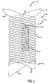
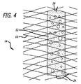
図1−5は、フレームまたは支持構造14と関連付けられた1つ以上の拡張可能プラグ12を採用する、本発明による、デバイス10を図示する。フレーム14は、好ましくは、略管状形態に編組または織成された単一ワイヤ16から形成されるが、また、複数の離散ワイヤを織成することによって、またはチューブをレーザ切断することによって、形成されることもできる。一実施例では、フレーム14は、外径約4.5ミリメートルおよび長さ約15ミリメートルを有する。ワイヤ16は、好ましくは、ニチノールとしても知られる、NiTiまたはニッケル−チタン合金から形成され、直径約0.00325インチを有する。
FIGS. 1-5 illustrate a
フレーム14は、外向きに拡開される、近位端部分18および遠位端部分20を有する。換言すると、近位端部分18および遠位端部分20は、半径方向外向きに延在する、突出要素22を採用する。ある実施形態では、突出要素22は、ループ、フック、突起、またはステープルの形態をとり、フレームと内腔との間の摩擦を増加させる傾向にある。これらの突出要素22は、フレーム14の半径方向力と併せて、フレーム14を定位置に保持する傾向にある。本特徴は、妨害される面積または内腔が、比較的に短いとき(これは、より長い内腔と比較して、フレーム14の総半径方向力を低減させる)、あるいは腸骨または頸動脈等の高流量が存在する場所において、特に有用である。
ある実施形態では、マーカーバンド、コイル、およびめっき等の種々の放射線不透過性マーカー(図示せず)が、フレーム14に接続される。例えば、マーカーは、突出要素22の端部、プラグ12の近傍、および/またはフレーム14の長さに沿って位置し、展開の間、操作者によるデバイス10の可視化、誘導、および送達を支援することができる。
In certain embodiments, various radiopaque markers (not shown) such as marker bands, coils, and plating are connected to the
本明細書に説明されるデバイス10等の形状記憶構造の弛緩または最小エネルギー状態構成の形成も、当技術分野において公知である。例えば、フレーム14の弛緩または最小エネルギー状態構成は、材料固定具を中心として、ワイヤ16を織成、巻回、または別様に操作することによって、形成される。所望の形態が、フレーム14に対して達成されると、フレーム14は、熱処理を受ける。例えば、フレーム14は、約500℃〜約1000℃の温度で約30〜90分間、維持される。熱処理後、フレーム14は、室温まで冷却され、超音波洗浄される。得られた二次構成は、それによって、恒久的にされ、デバイス10の弛緩または最小エネルギー状態構成となる。
Relaxation of a shape memory structure such as
一実施形態では、フレーム14は、複数の同一のまたは異なるワイヤ18の組み合わせから形成される。例えば、ワイヤ16は、ニチノール、鋼鉄、クロム−コバルト合金、および/または白金、および/またはTeflon、テレフタル酸ポリエチレン(PET)、またはポリエーテル・エーテル・ケトン(PEEK)等のポリマーから形成されてもよい。
In one embodiment, the
一実施形態では、フレーム14は、2011年1月7日出願の米国特許出願第13/003,277号、および2011年12月05日出願の米国特許出願第13/311,430号に見られるステントのいずれかであることができ、これらの米国出願は、その内容が、参照することによって本明細書に組み込まれる。
In one embodiment,
プラグ12は、例えば、ヒドロゲルあるいはPVAまたはヒドロゲル発泡体等の他の類似拡張性材料から形成される。図1−5に示されるように、プラグ12は、好ましくは、患者内に導入された後に拡張する、円筒形の形状に形成される。縮小または非拡張状態では、プラグ12は、好ましくは、直径約1ミリメートルおよび長さ約7ミリメートルを有する。拡張された非制約状態(例えば、水または血液へのプラグ12の暴露によって生じる)では、プラグ12は、好ましくは、直径約4ミリメートルおよび長さ約14ミリメートルを有する。
プラグ12は、例えば、生体適合性、マクロ多孔性またはマイクロ多孔性、親水性または疎水性ヒドロゲル発泡体材料を含む、種々の公知のポリマー材料から構築されることができる。好適な材料は、Greene Jr. et al.の米国特許第6,165,193号およびCruise et al.の米国特許第6,878,384号に説明され、これらの米国特許は、それぞれ、参照することによって本明細書に組み込まれる。プラグ12はまた、Jones et al.の米国特許第5,823,198号に説明されるポリビニルアルコール発泡体等のポリマーを備えてもよく、この米国特許は、参照することによって本明細書に組み込まれる。
本発明の別の実施形態では、プラグ12は、生体適合性、マクロ多孔性、親水性ヒドロゲル発泡体材料、特に、発泡体安定剤と、最大重量比約10%のマルチオレフィン官能性架橋結合剤と架橋結合されたフリーラジカル重合性親水性オレフィンモノマーのポリマーまたはコポリマーとを含む、マクロ多孔性固体として形成される、水膨張性発泡体マトリクスから作製される。本タイプの好適な材料は、Park et al.の米国特許第5,750,585号に説明され、この米国特許の開示は、参照することによって本明細書に組み込まれる。別の好適な材料は、例えば、その開示が、参照することによって本明細書に組み込まれる、Hyon et al.の米国特許第4,663,358号に説明されているように、水および水混和性有機溶媒から成る、混合溶媒中のポリビニルアルコール溶液から調製される、多孔性水和ポリビニルアルコール発泡体(PAF)ゲルである。さらに別の好適な材料は、Hyon et al.の米国特許第4,663,358号、「Hydrolysed Microspheres from Cross−Linked Polymethyl Methacrylate」、J. Neuroradiol., Vol. 18, pp. 61−69(1991)に論じられているようなPHEMAであり、これらは両方とも、参照することによって本明細書に組み込まれる。
In another embodiment of the invention, the
経皮的手技を行う目的のために、プラグ12のサイズを縮小させることが望ましくあり得る。これは、材料固定具を使用して、プラグを圧縮することによって機械的に、ポリマーをアルコール等の薬剤で脱水させることによって化学的に、またはこれらの方法の組み合わせを通して、行われてもよい。
It may be desirable to reduce the size of the
本発明のある実施形態では、プラグ12は、製造の際、放射線不透過性要素、例えば、プラグ12を形成する材料中に混合されたヨウ素またはタンタル粉を組み込み、展開の前および後に、プラグ12およびデバイス10の場所を視覚化するのに役立ち得る。
In certain embodiments of the present invention, the
プラグ12は、好ましくは、糸24によって、フレーム14と関連付けられる、または別様に、それに取着される。糸24は、例えば、直径約0.0009インチを有する、テレフタル酸ポリエチレン(PET)から形成される。糸24の一端は、プラグ12の一部を通して、かつフレーム14のワイヤ16の周囲に貫通または別様に通過され、次いで、ループを形成するように、糸24の第2の端部に固定される。複数の糸24がまた、採用され、フレーム14の寸法に沿って、同一のまたは異なる場所において、プラグ12をフレーム14に固着させてもよい。
ある実施形態では、プラグ12は、ポリプロピレンまたはEngage等のオレフィンエラストマーから形成される、糸24を採用することによって、フレーム14と関連付けられる。さらに他の実施形態では、プラグ12は、以下等の機械的方法によって、フレーム14と関連付けられる:プラグ12をその中に保持するケージまたはバスケットの形状にフレーム14を構築する;直接、プラグ12を通して、ワイヤ16の一部等、フレーム14の要素を貫通させる;プラグをフレーム14に糊着する;機械的把持要素をフレーム14に組み込み、プラグ12を保持する;または熱収縮性プラスチックを使用して、プラグ12をフレーム14に保持する。
In certain embodiments, the
フレーム14およびプラグ12が、関連付けられた後、デバイス10は、カテーテルまたはシース等の送達デバイス内に装填されることができる。より具体的実施例では、デバイス10は、後退可能シース内に位置する、内側プッシャ部材上に圧縮されることができる。一実施例では、送達デバイスは、約2−4ミリメートルの直径の内腔または血管内への送達のために、サイズ約4フレンチを有する。
After the
図6は、略「砂時計」形状側面プロファイルを有する、デバイス100の別の実施形態を図示する。より具体的には、デバイス100は、好ましくは、渦巻または実質的平面螺旋を形成する、単一ワイヤから構成される、フレーム102を含む。フレーム102のループは、概して、フレーム102の中央領域により小さい直径を有し、フレーム102の遠位および近位端に向かって、直径が増加する。
FIG. 6 illustrates another embodiment of the
1つ以上のプラグ12は、例えば、糸24を採用することによって、前述の実施形態に説明されるように、フレーム102の狭小中心部分に取着される。代替として、1つ以上のプラグ12は、フレーム102によって、プラグ12を貫通することによって、フレーム102に係留されてもよい。放射線不透過性マーカー(図示せず)もまた、デバイス10に関して前述に説明されるように、採用されてもよい。デバイス100は、送達カテーテルを介した送達のために、少なくとも部分的に、線形化(すなわち、コイル形状が、少なくとも部分的に、略線形形状に解巻される)され、展開される。
One or
デバイス100は、その長さと比較して、大きな直径を有する内腔、および治療デバイスが、複数の方向から力を受ける内腔を閉鎖するために、特に有用である。これらのタイプの内腔の実施例は、ASD、PFO、およびPDAである。デバイス100は、フレーム102の遠位端が、内腔(すなわち、心房または肺動脈内)の片側に留置され、プラグ12が、実質的に、内腔内に位置付けられ、および近位端が、内腔の他側に留置され得るため、これらの内腔を閉塞する際に有用である。フレーム102は、その元の実質的螺旋構成に戻る傾向があるため、中隔または脈管の両側に力を付与する傾向があり、したがって、内腔内にプラグを狭入する。
The
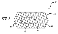
本発明の別の実施形態では、図7に示されるように、デバイス40は、概して、前述のフレーム14に類似するが、フレーム44の遠位端部分46および近位端部分48が、フレームの内部が、少なくとも部分的に、封鎖されるように閉鎖される点で異なる、フレーム44を採用する。本構成は、プラグ12を定位置に保持する糸24が、破損する場合、または水和プラグ12が、糸24単独によって係留され得ない場合、プラグ12が一方または両方の方向に移動することを防止する。
In another embodiment of the present invention, as shown in FIG. 7,
別の実施形態では、図8に示されるように、デバイス42は、前述のようであるが、上流の近位端50が、開放されたままであって、好ましくは、少なくとも部分的に、拡開される点で異なる、フレーム44を採用する。本構成では、プラグ12は、糸24によって、フレームに取着されてもよいが、そうである必要はない。フレーム44の下流または遠位の端部46が、閉鎖されるため、プラグ12は、下流に移動することを防止される。そのような構成では、プラグ12は、デバイスの展開の間の別個のステップとして、フレーム内に送達されてもよい。
In another embodiment, as shown in FIG. 8, the
さらに別の実施形態では、フレームの一端または両端は、少なくとも部分的に、例えば、メッシュ、交差または相互織成糸、あるいは布地で閉鎖もしくは被覆される。本被覆は、フレームの開放または閉鎖端のいずれかを覆って取着されることができ、プラグ12が、フレームおよび標的から離れて移動することを防止する。
In yet another embodiment, one or both ends of the frame are at least partially closed or covered with, for example, a mesh, cross or interwoven yarn, or fabric. The coating can be attached over either the open or closed end of the frame, preventing the
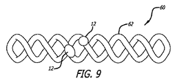
一実施形態では、図9に示されるように、デバイス60は、コルクネジ形状を形成する、捻転ワイヤを備える、フレーム62を含む。概して、フレーム62の捻転ワイヤは、比較的に均一または線形形状を維持するように、均一サイズのループを形成することができる。しかしながら、フレーム62のループはまた、三角形、円錐形、または砂時計形状を形成するように、可変サイズであってもよい。プラグ12は、直接、1つ以上のプラグ12を通して、ワイヤまたはコイルを貫通することによって、または糸24またはワイヤを使用して、プラグ12をフレームに繋着することによって、フレーム62に取着される。好ましくは、フレーム62は、標的内腔とほぼ同一のサイズまたは幾分大きいであろう、直径または高さを有するように定寸される。デバイス60は、カテーテルの内腔内または送達プッシャ上に、線形構成に圧縮することによって(例えば、ループのサイズを物理的に減少させることによって)、送達カテーテル内に装填されることができる。デバイス60は、標的内腔内で押動または解放されるにつれて、その弛緩捻転構成に拡張される。
In one embodiment, as shown in FIG. 9, the
図10Aおよび10Bは、それを通して複数のフィラメントまたはワイヤ114が通過する、プラグ12を備える、閉塞デバイス110のさらに別の実施形態を図示する。プラグ12は、例えば、ヒドロゲルあるいはPVAまたは発泡体等の他の類似拡張性材料から形成される。ワイヤ114は、デバイス110の略中心軸118に沿って、プラグ12を通して通過される。ワイヤ114は、中心軸118に対して、半径方向に相互から離れるように湾曲または屈曲するように構成(例えば、事前に形成)される。一実施例では、ワイヤ114は、長さ約6ミリメートルに対して、略中心軸118から離れるように屈曲または延在する。
10A and 10B illustrate yet another embodiment of an
ワイヤ114は、約120度離れて等、均一間隔において、または100、130、130度等の任意の種々の対称および非対称の非均一間隔において、半径方向に配向されることができる。一例示的構成では、ワイヤ114は、ニチノール等の形状記憶材料から構成され、直径約0.003インチを有し、放射線不透過性マーカー120で冠着される、端部を有する。代替として、ワイヤ114は、ハイポチューブをワイヤ114の所望の寸法にレーザ切断することによって、形成されてもよい。
The
デバイス110は、PDAを閉鎖するために、特に有用である。デバイス110は、送達システム内に圧潰され、従来の手段によって、標的部位に送達されることができる。一実施例では、プラグ12は、展開後、寸法約0.185インチに拡張し、標的部位(例えば、PDA)を封鎖または別様に密閉する。拡張され、半径方向に湾曲したワイヤ114は、好ましくは、欠陥の両側に展開され、それによって、移動を防止するように、プラグ12の支持を提供する。デバイス110は、任意の数のワイヤ114を含んでもよいが、好ましくは、少なくとも2〜20本のワイヤ、より好ましくは、少なくとも3〜6本のワイヤであることに留意されたい。有利には、デバイス110は、比較的に構築が単純であって、多くの他のデバイス形状と比較して、より小さい送達プロファイルを有する傾向にある。
前述の実施形態は、拡張可能プラグ12の使用を含んだが、また、プラグ12を伴わずに、これらのデバイスのうちの1つ以上を使用することも可能である。より具体的には、材料が、遮断を生じさせるように、展開されたデバイスの上流またはそれに隣接して追加されることができる。例えば、1つ以上の塞栓性コイル(ヒドロゲル等の拡張可能材料を含んでもよく、または含まなくてもよい)が、展開および拡張デバイス内に送達されることができる。
Although the foregoing embodiments include the use of an
図11および12は、塞栓性コイル168等の塞栓性材料で充填され得る、血管内自己拡張式ステントタイプデバイス140のそのような実施例の1つを図示する。液体塞栓性材料(例えば、Onyx)、塞栓形成ビーズ(例えば、Embosphere)、または他の塞栓形成剤等の他の塞栓性材料もまた、使用されることができる。デバイス140は、フレーム14に関して前述のように、遠位端144および近位端146の両方において円周方向に開放される、フレームまたは支持構造142を備える。締め付けられた中心区分148は、デバイス140の中心内腔を妨害し、それによって、後続塞栓性材料送達のための安定した障壁として作用する、塞栓性材料捕捉領域を生成する。中心148は、糸、ワイヤ、クリップ、または他の締結部材によって、ともに織成または締結され、縮小直径および制御展開をもたらすことができる。
FIGS. 11 and 12 illustrate one such embodiment of an intravascular self-expanding stent-
デバイス142が、標的閉塞場所で展開されると、第2の送達カテーテル141(または、可能性として、同一の送達カテーテル)は、デバイス142の近位端146まで前進され、塞栓性材料は、デバイス142の近位半分に展開される。本実施例では、塞栓性材料は、1つ以上の塞栓性コイル168である。これらの塞栓性コイル168は、患者の血液内で拡張する、またはコイル168から分離される拡張性材料を含み得る、拡張性コーティング(ヒドロゲル等)を含んでもよい。本点では、デバイス142の半分は、材料で充填され、それによって、内腔152を通る血流の大部分を閉塞する。経時的に、本閉塞は、塞栓性コイル168上の任意の拡張性コーティングの拡張、血液の凝固および/または塞栓性コイル168を覆う組織成長によって、完全に遮断された状態となる可能性が高いであろう。
When the
図13は、概して、図8の前述のデバイス42に類似するが、プラグ12を伴わない、血管内自己拡張式ステントタイプデバイス160を図示する。デバイス160は、塞栓性コイル168または他の塞栓性材料と併用されるとき、内腔閉塞を促進する、フレーム162を備える。フレーム14に関して前述のように、フレーム162の下流または遠位の端部164のみ、少なくとも部分的に、閉鎖され、近位端166は、開放される。
FIG. 13 illustrates an intravascular self-expanding stent-
前述の実施形態同様に、デバイス162は、内腔152内の所望の閉塞点まで送達される。次に、送達カテーテル141の遠位端は、フレーム構造162に隣接して、またはさらにその内側に部分的に、位置付けられ、塞栓性コイル168が、デバイス160内で展開される。フレーム162の下流または遠位の端部164は、安定した障壁として作用するように閉鎖されるため、塞栓性コイル168は、内腔152を通して下流に移動することを防止され、したがって、内腔152を閉塞する。再び、ヒドロゲル等の他の塞栓性材料が、デバイス160および塞栓性コイル168と併用されてもよい。
Similar to the previous embodiment,
代替として、デバイス162の両端が、閉鎖されてもよく、塞栓性コイル168等の塞栓性材料が、織成内の開口を通して、デバイスの空洞の内側に送達されることができる。例えば、塞栓性コイル送達カテーテルが、その織成ワイヤによって生成された開口を通して挿入されることができ、塞栓性コイルは、デバイス162内に前進されることができる。
Alternatively, both ends of
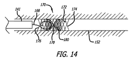
図14は、外側係留ステント層172および内側閉塞ステント層180を含む、二重層ステントデバイス170を図示する。概して、本二重層ステントデバイス170は、2011年1月7日出願の米国特許出願第13/003,277号および2011年12月05日出願の米国特許出願第13/311,430号(これらの内容は、参照することによって本明細書に組み込まれる)における教示に類似し、それに従って構築されることができる。外側ステント層172は、内腔152に対して拡張し、デバイス170を内腔152に対して係留する一方、内側ステント層180は、中央場所178近傍で締め付けられ、砂時計形状を形成する。代替として、内側ステント層180は、その遠位端で締め付けられ、図13におけるデバイス160のものに類似する形状を生成することができる。
FIG. 14 illustrates a
好ましくは、塞栓性コイル168等の閉塞材料は、デバイス170の近位端176内に送達され、内腔152を閉塞することができる。内側ステント層180は、離散追加閉塞材料に加え、または代わりに、ヒドロゲル等の拡張性材料でコーティングされてもよい。
Preferably, an occlusive material, such as an
外側係留ステント層172は、好ましくは、内側閉塞ステント層180を構成するものより大きい直径を有する、1つ以上のワイヤから構成される。加えて、外側層172は、両層が拡張構成にあるとき、内側ステント層180のものより大きい開口を有するように織成されることができる。本点では、外側層172は、係留のための比較的により多くの半径方向外向き力を提供することができる一方、内側層180は、比較的により微細な織成閉塞性障壁を提供することができる。
The outer
好ましくは、内側ステント層180は、その近位端および随意にその遠位端において、外側ステント層172に接続される。加えて、内側ステント層180は、外側ステント層の近位端176、遠位端174、中央、またはその間の任意の位置近傍に位置することができる。
Preferably, the
デバイス170は、塞栓術コイルの抜去を防止することによって、内腔を閉塞する、先行技術内腔妨害デバイスと比較して、いくつかの利点を有する。本発明は、その取着機構のため、再被覆材料の部分的展開を可能にし、デバイスのより制御された留置を可能にする。さらに、本発明は、5フレンチ以上のサイズのカテーテルと比較して、遥かに小さい、恐らく、1.7フレンチまでのカテーテルと併用されることができる。これは、本発明が、より蛇行性かつ遠位の内腔を操向することを可能にし、それによって、患者のより広範囲を治療可能にする。加えて、これは、同一のカテーテルが、デバイスならびに塞栓性コイルおよび材料の両方を送達するために使用されることを可能にする。さらに、本発明は、動脈サイズに調整された自己拡張式半径方向力を使用することによって、内腔壁に及ぼされる任意の外傷を最小限にする。
140、160、および170等の前述のデバイスは、限定されないが、生体活性、血栓形成、ヒドロゲル、または他の治療用コーティングを含む、種々の材料で作製されることができる。さらに、これらのデバイスは、種々の異なるサイズおよび長さに作製されることができ、ステントの長さに沿って、任意の場所に締め付けられたまたは封入されることができる。臨床転帰を改善するために、デバイスは、例えば、生体活性またはヒドロゲルコーティングでコーティングされることができる。デバイスは、可変間隙率と併用され、全体的または部分的流動閉塞を提供し、内腔を十分に閉塞するために要求される塞栓性材料の量を制限することができる。 The aforementioned devices such as 140, 160, and 170 can be made of a variety of materials, including but not limited to bioactivity, thrombus formation, hydrogels, or other therapeutic coatings. Further, these devices can be made in a variety of different sizes and lengths and can be clamped or encapsulated anywhere along the length of the stent. To improve clinical outcome, the device can be coated with, for example, a bioactive or hydrogel coating. The device can be used in conjunction with a variable porosity to provide total or partial flow occlusion and limit the amount of embolic material required to fully occlude the lumen.
前述のデバイスの送達は、種々の送達システムを使用して達成されることができる。例えば、デバイスは、デバイスの一端または両端を、内腔内に位置付けおよび再位置付けされ得るように、デバイスを保持する、送達プッシャに取着することによって、特殊プッシャまたはガイドワイヤを伴う、カテーテルまたはシースを通して、デバイスを押動させることにより送達されることができる。デバイスは、次いで、例えば、機械的に、熱的に、油圧的、または電解で、デバイスおよび送達システムを関連付けている取着部材を切断することによって、選択的に、送達システムから切り離される。 Delivery of the aforementioned devices can be accomplished using a variety of delivery systems. For example, the device is a catheter or sheath with a special pusher or guide wire by attaching to a delivery pusher that holds the device so that one or both ends of the device can be positioned and repositioned within the lumen Can be delivered by pushing the device through. The device is then selectively disconnected from the delivery system, for example, by mechanically, thermally, hydraulically, or electrolytically cutting the attachment member that associates the device with the delivery system.
一実施形態では、デバイスは、デバイスの一端に位置付けられる、少なくとも1つの放射線不透過性マーカーバンドを組み込む。マーカーは、送達プッシャ上の噛合要素に相互係止するように構成される。ユーザは、デバイスを引くための相互係止を使用して、デバイスを部分的に展開し、後退させることができる。送達システムからのデバイスの解放は、例えば、送達カテーテルからインプラントの大部分を押動させる、および/または送達カテーテルを後退させ、相互係止解除に曝すことによって、達成される。 In one embodiment, the device incorporates at least one radiopaque marker band positioned at one end of the device. The marker is configured to interlock with a mating element on the delivery pusher. The user can partially deploy and retract the device using an interlock to pull the device. Release of the device from the delivery system is accomplished, for example, by pushing the majority of the implant from the delivery catheter and / or retracting the delivery catheter and exposing it to interlock release.
別の実施形態では、単繊維が、デバイスの近位端を通して巻着され、次いで、電流によって起動され得る、ヒータを組み込む、送達プッシャに取着される。ユーザは、デバイスを完全または部分的に展開し、次いで、必要に応じて、デバイスを再位置付けまたは復元することができる。デバイスが、所望の場所にあるとき、ユーザは、ヒータを起動し、それによって、単繊維をデバイスから分断および解放させる。 In another embodiment, the monofilament is wound through the proximal end of the device and then attached to a delivery pusher that incorporates a heater that can be activated by an electric current. The user can fully or partially deploy the device and then reposition or restore the device as needed. When the device is in the desired location, the user activates the heater, thereby causing the monofilament to break and release from the device.
さらに別の実施形態では、デバイスの一端は、非外傷性先端を組み込む一方、他端は、送達プッシャにはんだ付けされる。ユーザは、必要に応じて、デバイスを展開および再位置付けし、次いで、送達プッシャを通して、電流を通過させることができる。電流は、患者の血液中において、はんだを加速度的に浸食させ、プッシャにはんだ付けされたデバイスの端部を解放させる。 In yet another embodiment, one end of the device incorporates an atraumatic tip while the other end is soldered to a delivery pusher. The user can deploy and reposition the device and then pass current through the delivery pusher as needed. The current causes the solder to erode at an accelerated rate in the patient's blood, releasing the end of the device soldered to the pusher.
代替として、デバイスの端部は、2つの端部を有する感熱式糸が、連結部を通過されるように構成される、放射線不透過性材料のチューブ等の連結要素を組み込む。糸の一端は、デバイスに括着され、糸の他端は、送達プッシャの端部に組み込まれたヒータを通して通過される。デバイスは、前述のように、ユーザによって切り離される。 Alternatively, the end of the device incorporates a coupling element, such as a tube of radiopaque material, configured such that a thermosensitive yarn having two ends is passed through the coupling. One end of the yarn is tied to the device and the other end of the yarn is passed through a heater built into the end of the delivery pusher. The device is disconnected by the user as described above.
別の実施形態では、送達システムは、プッシャ部材を覆って配置されるシースを含む。ステントデバイスが、プッシャの遠位端を覆って圧縮され、シースが、ステントを覆って留置される。本点では、ステントは、部分的に、摩擦力を介して、定位置に維持される。そのような送達システムの付加的詳細は、2011年1月7日出願の米国特許出願第13/003,277号および2011年12月05日出願の米国特許出願第13/311,430号に見出され得、両方とも、参照することによって既に本明細書に組み込まれている。 In another embodiment, the delivery system includes a sheath disposed over the pusher member. The stent device is compressed over the distal end of the pusher and the sheath is placed over the stent. At this point, the stent is maintained in place, in part, via frictional forces. Additional details of such delivery systems can be found in US Patent Application No. 13 / 003,277 filed January 7, 2011 and US Patent Application No. 13 / 311,430 filed December 05, 2011. Both of which are already incorporated herein by reference.
本デバイスおよび方法は、先行技術に勝るいくつかの利点を有する。先行技術着脱可能バルーンと比較して、本発明のデバイスは、留置がより容易であって、展開のためにより少ない数のステップを要求し、かつ留置後、例えば、バルーンベースのデバイスが、経時的に漏出し始める場合、移動する傾向が少ない。 The device and method have several advantages over the prior art. Compared to prior art detachable balloons, the device of the present invention is easier to deploy and requires fewer steps for deployment, and after deployment, for example, a balloon-based device is If you start leaking, there is less tendency to move.
本発明は、特定の実施形態および用途の観点から説明されたが、当業者は、本教示に照らして、請求される発明の精神から逸脱することなく、またはその範囲を超えることなく、付加的実施形態および修正を生成し得る。故に、本明細書の図面および説明は、一例として、もたらされ、本発明の理解を促進し、その範囲を限定するように解釈されるべきではないことを理解されたい。 Although the invention has been described in terms of particular embodiments and applications, those skilled in the art will recognize additional teachings in light of the present teachings without departing from or exceeding the spirit of the claimed invention. Embodiments and modifications may be generated. Accordingly, it is to be understood that the drawings and descriptions herein are provided by way of example and should not be construed to promote or facilitate the understanding of the invention.
Claims (28)
圧縮構成および拡張構成を有する、略管状支持構造と、
圧縮構成および拡張構成を有し、前記管状支持構造内に固定される、プラグと
を備える、デバイス。 An occlusive device,
A generally tubular support structure having a compressed configuration and an expanded configuration;
And a plug having a compressed configuration and an expanded configuration and secured within the tubular support structure.
圧縮構成および拡張構成を有する、支持構造を備え、
前記支持構造は、管状領域と、前記支持構造に送達された塞栓性材料を含有するための塞栓性材料捕捉領域とを有する、デバイス。 An occlusive device,
A support structure having a compression configuration and an expansion configuration;
The device wherein the support structure has a tubular region and an embolic material capture region for containing the embolic material delivered to the support structure.
前記閉塞デバイスのフレーム構造を拡張させ、前記内腔の壁に係合させるステップと、
閉塞物を前記閉塞デバイスのフレーム構造内に送達するステップと、
前記閉塞物を前記フレーム構造で捕捉し、前記内腔を閉塞させるステップと
を含む、方法。 Advancing the occlusion device to the target area of the lumen;
Expanding the frame structure of the occlusion device to engage the lumen wall;
Delivering an obstruction into the frame structure of the occlusion device;
Capturing the obstruction with the frame structure and occluding the lumen.
圧縮構成および拡張構成を有する、略管状支持構造と、
脱水構成および水和構成を有し、前記管状支持構造内に固定される、プラグと
を備える、デバイス。 An occlusive device,
A generally tubular support structure having a compressed configuration and an expanded configuration;
A device having a dewatering configuration and a hydration configuration and secured within the tubular support structure.
Applications Claiming Priority (3)
| Application Number | Priority Date | Filing Date | Title |
|---|---|---|---|
| US201161485065P | 2011-05-11 | 2011-05-11 | |
| US61/485,065 | 2011-05-11 | ||
| PCT/US2012/037621 WO2012155093A1 (en) | 2011-05-11 | 2012-05-11 | Device for occluding a lumen |
Publications (2)
| Publication Number | Publication Date |
|---|---|
| JP2014522263A true JP2014522263A (en) | 2014-09-04 |
| JP2014522263A5 JP2014522263A5 (en) | 2015-05-21 |
Family
ID=47139706
Family Applications (1)
| Application Number | Title | Priority Date | Filing Date |
|---|---|---|---|
| JP2014510514A Pending JP2014522263A (en) | 2011-05-11 | 2012-05-11 | Device for occluding a lumen |
Country Status (5)
| Country | Link |
|---|---|
| US (1) | US10058330B2 (en) |
| EP (1) | EP2707077B1 (en) |
| JP (1) | JP2014522263A (en) |
| CA (1) | CA2835427A1 (en) |
| WO (1) | WO2012155093A1 (en) |
Cited By (2)
| Publication number | Priority date | Publication date | Assignee | Title |
|---|---|---|---|---|
| JP2018534995A (en) * | 2015-10-30 | 2018-11-29 | インキュメデックス インコーポレイテッド | Devices and methods for delivering implants against vascular disorders |
| US11090055B2 (en) | 2015-10-30 | 2021-08-17 | Incumedx Inc. | Devices and methods for delivering an implant to a vascular disorder |
Families Citing this family (32)
| Publication number | Priority date | Publication date | Assignee | Title |
|---|---|---|---|---|
| US9498604B2 (en) | 1997-11-12 | 2016-11-22 | Genesis Technologies Llc | Medical device and method |
| US9861346B2 (en) | 2003-07-14 | 2018-01-09 | W. L. Gore & Associates, Inc. | Patent foramen ovale (PFO) closure device with linearly elongating petals |
| US20110257723A1 (en) | 2006-11-07 | 2011-10-20 | Dc Devices, Inc. | Devices and methods for coronary sinus pressure relief |
| WO2008124603A1 (en) | 2007-04-05 | 2008-10-16 | Nmt Medical, Inc. | Septal closure device with centering mechanism |
| US9138213B2 (en) * | 2008-03-07 | 2015-09-22 | W.L. Gore & Associates, Inc. | Heart occlusion devices |
| US20130165967A1 (en) | 2008-03-07 | 2013-06-27 | W.L. Gore & Associates, Inc. | Heart occlusion devices |
| US9119607B2 (en) | 2008-03-07 | 2015-09-01 | Gore Enterprise Holdings, Inc. | Heart occlusion devices |
| US8956389B2 (en) | 2009-06-22 | 2015-02-17 | W. L. Gore & Associates, Inc. | Sealing device and delivery system |
| US20120029556A1 (en) | 2009-06-22 | 2012-02-02 | Masters Steven J | Sealing device and delivery system |
| US9561094B2 (en) | 2010-07-23 | 2017-02-07 | Nfinium Vascular Technologies, Llc | Devices and methods for treating venous diseases |
| EP2673038B1 (en) | 2011-02-10 | 2017-07-19 | Corvia Medical, Inc. | Apparatus to create and maintain an intra-atrial pressure relief opening |
| US8562643B2 (en) * | 2011-04-21 | 2013-10-22 | Cook Medical Technologies Llc | Self closing occulsion device with a twist |
| US9770232B2 (en) | 2011-08-12 | 2017-09-26 | W. L. Gore & Associates, Inc. | Heart occlusion devices |
| EP3957276A1 (en) | 2012-05-31 | 2022-02-23 | Javelin Medical Ltd. | Device for embolic protection |
| WO2014102767A2 (en) * | 2012-12-27 | 2014-07-03 | Javelin Medical Ltd. | Apparatus and method of monofilament implant delivery in a body vessel of a patient |
| US10828019B2 (en) | 2013-01-18 | 2020-11-10 | W.L. Gore & Associates, Inc. | Sealing device and delivery system |
| ES2895968T3 (en) | 2013-01-18 | 2022-02-23 | Javelin Medical Ltd | Monofilament implants and systems for supplying the same |
| US9592110B1 (en) | 2013-12-06 | 2017-03-14 | Javelin Medical, Ltd. | Systems and methods for implant delivery |
| US10675450B2 (en) | 2014-03-12 | 2020-06-09 | Corvia Medical, Inc. | Devices and methods for treating heart failure |
| EP3151904A4 (en) | 2014-06-04 | 2018-02-14 | Nfinium Vascular Technologies, LLC | Low radial force vascular device and method of occlusion |
| US9808230B2 (en) | 2014-06-06 | 2017-11-07 | W. L. Gore & Associates, Inc. | Sealing device and delivery system |
| WO2016014821A1 (en) | 2014-07-23 | 2016-01-28 | Corvia Medical, Inc. | Devices and methods for treating heart failure |
| US10932786B2 (en) * | 2014-11-04 | 2021-03-02 | Corvia Medical, Inc. | Devices and methods for treating patent ductus arteriosus |
| WO2016161344A1 (en) | 2015-04-01 | 2016-10-06 | Boston Scientific Scimed, Inc. | Systems and methods for delivery of gel embolics |
| US20170007260A1 (en) * | 2015-07-10 | 2017-01-12 | Boston Scientific Scimed, Inc. | Vascular occlusion devices |
| US11478251B2 (en) * | 2015-10-28 | 2022-10-25 | Jayandiran Pillai | Aneurysm occluder |
| JP7222886B2 (en) | 2016-10-21 | 2023-02-15 | ジャベリン メディカル リミテッド | Systems, methods, and devices for embolic protection |
| EP3576644A1 (en) * | 2017-03-13 | 2019-12-11 | Boston Scientific Scimed, Inc. | Occlusive medical device system |
| WO2019190918A1 (en) * | 2018-03-29 | 2019-10-03 | Boston Scientific Scimed, Inc. | Systems and methods for performing endoscopic procedures |
| US11399840B2 (en) | 2019-08-13 | 2022-08-02 | Covidien Lp | Implantable embolization device |
| US11672946B2 (en) | 2019-09-24 | 2023-06-13 | Boston Scientific Scimed, Inc. | Protection and actuation mechanism for controlled release of implantable embolic devices |
| US20220054139A1 (en) * | 2020-08-18 | 2022-02-24 | Merit Medical Systems, Inc. | Embolic basket, particles, and related methods |
Citations (8)
| Publication number | Priority date | Publication date | Assignee | Title |
|---|---|---|---|---|
| JPH09510122A (en) * | 1994-03-09 | 1997-10-14 | クック インコーポレイティッド | Endovascular treatment system and percutaneous release mechanism therefor |
| JPH10225458A (en) * | 1997-02-12 | 1998-08-25 | Schneider Usa Inc | Medical system with area contracted for clogging flow of fluid within internal tube cavity |
| US20060009798A1 (en) * | 2004-02-02 | 2006-01-12 | Ams Research Corporation | Methods and devices for occluding body lumens and/or enhancing tissue ingrowth |
| US20060052820A1 (en) * | 2004-09-03 | 2006-03-09 | Nancy Haig | Reversible vessel seal |
| US20070227544A1 (en) * | 2006-03-30 | 2007-10-04 | Betsy Swann | Methods and devices for deployment into a lumen |
| US20090177221A1 (en) * | 2005-07-11 | 2009-07-09 | Bernhard Kramann | Endovascular implant for occlusion of a blood vessel |
| US20090254176A1 (en) * | 2008-03-27 | 2009-10-08 | Ab Medica S.P.A. | Valve prosthesis for implantation in body channels |
| US20100262177A1 (en) * | 2009-04-08 | 2010-10-14 | Frigstad John R | Body lumen occlusion device and method |
Family Cites Families (269)
| Publication number | Priority date | Publication date | Assignee | Title |
|---|---|---|---|---|
| US3868956A (en) | 1972-06-05 | 1975-03-04 | Ralph J Alfidi | Vessel implantable appliance and method of implanting it |
| US4140126A (en) | 1977-02-18 | 1979-02-20 | Choudhury M Hasan | Method for performing aneurysm repair |
| US4130904A (en) | 1977-06-06 | 1978-12-26 | Thermo Electron Corporation | Prosthetic blood conduit |
| US4286341A (en) | 1979-04-16 | 1981-09-01 | Iowa State University Research Foundation, Inc. | Vascular prosthesis and method of making the same |
| BR8208063A (en) | 1981-09-16 | 1984-01-10 | Hans Ivar Wallsten | DEVICE FOR APPLICATION IN BLOOD VESSELS OR OTHER DIFFICULT ACCESS PLACES AND THEIR USE |
| US4734097A (en) | 1981-09-25 | 1988-03-29 | Nippon Oil Company, Ltd. | Medical material of polyvinyl alcohol and process of making |
| SE445884B (en) | 1982-04-30 | 1986-07-28 | Medinvent Sa | DEVICE FOR IMPLANTATION OF A RODFORM PROTECTION |
| JPS5956446A (en) | 1982-09-24 | 1984-03-31 | Nippon Oil Co Ltd | Method for lowering flexibility of frozen polyvinyl alcohol gel |
| US4512338A (en) | 1983-01-25 | 1985-04-23 | Balko Alexander B | Process for restoring patency to body vessels |
| GB2139898B (en) | 1983-05-09 | 1986-08-06 | Donald James Highgate | Deformable polymeric compositions |
| US4562596A (en) | 1984-04-25 | 1986-01-07 | Elliot Kornberg | Aortic graft, device and method for performing an intraluminal abdominal aortic aneurysm repair |
| US4577631A (en) | 1984-11-16 | 1986-03-25 | Kreamer Jeffry W | Aneurysm repair apparatus and method |
| JPH0678460B2 (en) | 1985-05-01 | 1994-10-05 | 株式会社バイオマテリアル・ユニバース | Porous transparent polyvinyl alcohol gel |
| US4733665C2 (en) | 1985-11-07 | 2002-01-29 | Expandable Grafts Partnership | Expandable intraluminal graft and method and apparatus for implanting an expandable intraluminal graft |
| WO1987004935A1 (en) | 1986-02-24 | 1987-08-27 | Fischell Robert | An intravascular stent and percutaneous insertion system |
| US4990582A (en) | 1986-07-18 | 1991-02-05 | Salamone Joseph C | Fluorine containing soft contact lens hydrogels |
| US4740207A (en) | 1986-09-10 | 1988-04-26 | Kreamer Jeffry W | Intralumenal graft |
| JPH0696023B2 (en) | 1986-11-10 | 1994-11-30 | 宇部日東化成株式会社 | Artificial blood vessel and method for producing the same |
| US4852568A (en) | 1987-02-17 | 1989-08-01 | Kensey Nash Corporation | Method and apparatus for sealing an opening in tissue of a living being |
| US4800882A (en) | 1987-03-13 | 1989-01-31 | Cook Incorporated | Endovascular stent and delivery system |
| US5041126A (en) | 1987-03-13 | 1991-08-20 | Cook Incorporated | Endovascular stent and delivery system |
| AU3770989A (en) | 1988-05-23 | 1989-12-12 | Lynn L. Augspurger | Method and system for making prosthetic device |
| US5041292A (en) | 1988-08-31 | 1991-08-20 | Theratech, Inc. | Biodegradable hydrogel matrices for the controlled release of pharmacologically active agents |
| US5019090A (en) | 1988-09-01 | 1991-05-28 | Corvita Corporation | Radially expandable endoprosthesis and the like |
| US4994069A (en) | 1988-11-02 | 1991-02-19 | Target Therapeutics | Vaso-occlusion coil and method |
| US5162430A (en) | 1988-11-21 | 1992-11-10 | Collagen Corporation | Collagen-polymer conjugates |
| US4856516A (en) | 1989-01-09 | 1989-08-15 | Cordis Corporation | Endovascular stent apparatus and method |
| US5078726A (en) | 1989-02-01 | 1992-01-07 | Kreamer Jeffry W | Graft stent and method of repairing blood vessels |
| US5015253A (en) | 1989-06-15 | 1991-05-14 | Cordis Corporation | Non-woven endoprosthesis |
| US5171262A (en) | 1989-06-15 | 1992-12-15 | Cordis Corporation | Non-woven endoprosthesis |
| US5084065A (en) | 1989-07-10 | 1992-01-28 | Corvita Corporation | Reinforced graft assembly |
| EP0408245B1 (en) | 1989-07-13 | 1994-03-02 | American Medical Systems, Inc. | Stent placement instrument |
| US5035706A (en) | 1989-10-17 | 1991-07-30 | Cook Incorporated | Percutaneous stent and method for retrieval thereof |
| US5843089A (en) | 1990-12-28 | 1998-12-01 | Boston Scientific Corporation | Stent lining |
| DK0441516T3 (en) | 1990-02-08 | 1995-06-12 | Howmedica | Inflatable catheter |
| DE69115471T2 (en) | 1990-03-30 | 1996-05-02 | Alza Corp | DEVICE FOR IONTOPHORETIC ADMINISTRATION OF MEDICINES |
| US5158548A (en) | 1990-04-25 | 1992-10-27 | Advanced Cardiovascular Systems, Inc. | Method and system for stent delivery |
| US5449372A (en) | 1990-10-09 | 1995-09-12 | Scimed Lifesystems, Inc. | Temporary stent and methods for use and manufacture |
| US5410016A (en) | 1990-10-15 | 1995-04-25 | Board Of Regents, The University Of Texas System | Photopolymerizable biodegradable hydrogels as tissue contacting materials and controlled-release carriers |
| US5133731A (en) | 1990-11-09 | 1992-07-28 | Catheter Research, Inc. | Embolus supply system and method |
| US5135536A (en) | 1991-02-05 | 1992-08-04 | Cordis Corporation | Endovascular stent and method |
| DE4104702C2 (en) | 1991-02-15 | 1996-01-18 | Malte Neuss | Implants for organ pathways in spiral form |
| US5116365A (en) | 1991-02-22 | 1992-05-26 | Cordis Corporation | Stent apparatus and method for making |
| US5197978B1 (en) | 1991-04-26 | 1996-05-28 | Advanced Coronary Tech | Removable heat-recoverable tissue supporting device |
| US5304200A (en) | 1991-05-29 | 1994-04-19 | Cordis Corporation | Welded radially expandable endoprosthesis and the like |
| USD359802S (en) | 1991-06-28 | 1995-06-27 | Cook Incorporated | Vascular stent |
| US5226911A (en) | 1991-10-02 | 1993-07-13 | Target Therapeutics | Vasoocclusion coil with attached fibrous element(s) |
| US5366504A (en) | 1992-05-20 | 1994-11-22 | Boston Scientific Corporation | Tubular medical prosthesis |
| ES2109969T3 (en) | 1991-10-11 | 1998-02-01 | Angiomed Ag | PROCEDURE FOR THE DILATION OF A STENOSIS. |
| US5256146A (en) | 1991-10-11 | 1993-10-26 | W. D. Ensminger | Vascular catheterization system with catheter anchoring feature |
| US5258042A (en) | 1991-12-16 | 1993-11-02 | Henry Ford Health System | Intravascular hydrogel implant |
| US5192297A (en) | 1991-12-31 | 1993-03-09 | Medtronic, Inc. | Apparatus and method for placement and implantation of a stent |
| US5484449A (en) | 1992-01-07 | 1996-01-16 | Medtronic, Inc. | Temporary support for a body lumen and method |
| US5405377A (en) | 1992-02-21 | 1995-04-11 | Endotech Ltd. | Intraluminal stent |
| GR920100104A (en) | 1992-03-13 | 1993-11-30 | Christodoulos I Stefanadis | Temporary luminal stent for the support of the vascular wall. |
| DE4213597A1 (en) | 1992-04-24 | 1993-10-28 | Klaus Draenert | Femoral prosthesis component to be anchored with bone cement and process for its production |
| WO1995014500A1 (en) | 1992-05-01 | 1995-06-01 | Beth Israel Hospital | A stent |
| US5342387A (en) | 1992-06-18 | 1994-08-30 | American Biomed, Inc. | Artificial support for a blood vessel |
| US5514379A (en) | 1992-08-07 | 1996-05-07 | The General Hospital Corporation | Hydrogel compositions and methods of use |
| US5312415A (en) | 1992-09-22 | 1994-05-17 | Target Therapeutics, Inc. | Assembly for placement of embolic coils using frictional placement |
| US5382259A (en) | 1992-10-26 | 1995-01-17 | Target Therapeutics, Inc. | Vasoocclusion coil with attached tubular woven or braided fibrous covering |
| US5382260A (en) | 1992-10-30 | 1995-01-17 | Interventional Therapeutics Corp. | Embolization device and apparatus including an introducer cartridge and method for delivering the same |
| US5690666A (en) | 1992-11-18 | 1997-11-25 | Target Therapeutics, Inc. | Ultrasoft embolism coils and process for using them |
| FR2699809B1 (en) | 1992-12-28 | 1995-02-17 | Celsa Lg | Device which can selectively constitute a temporary blood filter. |
| AU689096B2 (en) | 1993-01-27 | 1998-03-26 | Intra Therapeutics, Inc. | Vascular and coronary stents |
| US5716410A (en) | 1993-04-30 | 1998-02-10 | Scimed Life Systems, Inc. | Temporary stent and method of use |
| US5480423A (en) | 1993-05-20 | 1996-01-02 | Boston Scientific Corporation | Prosthesis delivery |
| EP0627201B1 (en) | 1993-06-02 | 1998-07-22 | Schneider (Europe) GmbH | Device for releasing a self-expanding endoprosthesis |
| US5464449A (en) | 1993-07-08 | 1995-11-07 | Thomas J. Fogarty | Internal graft prosthesis and delivery system |
| BR9405622A (en) | 1993-09-30 | 1999-09-08 | Endogad Res Pty Ltd | Intraluminal Graft |
| AU8012394A (en) | 1993-10-01 | 1995-05-01 | Emory University | Self-expanding intraluminal composite prosthesis |
| US5389106A (en) | 1993-10-29 | 1995-02-14 | Numed, Inc. | Impermeable expandable intravascular stent |
| US5476505A (en) | 1993-11-18 | 1995-12-19 | Advanced Cardiovascular Systems, Inc. | Coiled stent and delivery system |
| FR2714815B1 (en) | 1994-01-10 | 1996-03-08 | Microfil Ind Sa | Elastic prosthesis to widen a duct, in particular a blood vessel. |
| US5795331A (en) | 1994-01-24 | 1998-08-18 | Micro Therapeutics, Inc. | Balloon catheter for occluding aneurysms of branch vessels |
| US5609627A (en) | 1994-02-09 | 1997-03-11 | Boston Scientific Technology, Inc. | Method for delivering a bifurcated endoluminal prosthesis |
| US5415664A (en) | 1994-03-30 | 1995-05-16 | Corvita Corporation | Method and apparatus for introducing a stent or a stent-graft |
| KR0141431B1 (en) | 1994-05-17 | 1998-07-01 | 김상웅 | Biodegradable hydrogel copolymer |
| US5540701A (en) | 1994-05-20 | 1996-07-30 | Hugh Sharkey | Passive fixation anastomosis method and device |
| US5499995C1 (en) | 1994-05-25 | 2002-03-12 | Paul S Teirstein | Body passageway closure apparatus and method of use |
| DE69532856T2 (en) | 1994-10-17 | 2005-04-21 | Raymedica Inc | Spinal disc-GRAFT |
| US5630829A (en) | 1994-12-09 | 1997-05-20 | Intervascular, Inc. | High hoop strength intraluminal stent |
| US5814062A (en) | 1994-12-22 | 1998-09-29 | Target Therapeutics, Inc. | Implant delivery assembly with expandable coupling/decoupling mechanism |
| US5578074A (en) | 1994-12-22 | 1996-11-26 | Target Therapeutics, Inc. | Implant delivery method and assembly |
| AU719980B2 (en) | 1995-02-22 | 2000-05-18 | Menlo Care, Inc. | Covered expanding mesh stent |
| US5750585A (en) | 1995-04-04 | 1998-05-12 | Purdue Research Foundation | Super absorbent hydrogel foams |
| US5911731A (en) | 1995-04-20 | 1999-06-15 | Target Therapeutics, Inc. | Anatomically shaped vasoocclusive devices |
| US5609628A (en) | 1995-04-20 | 1997-03-11 | Keranen; Victor J. | Intravascular graft and catheter |
| US5645558A (en) | 1995-04-20 | 1997-07-08 | Medical University Of South Carolina | Anatomically shaped vasoocclusive device and method of making the same |
| US5613981A (en) | 1995-04-21 | 1997-03-25 | Medtronic, Inc. | Bidirectional dual sinusoidal helix stent |
| US5624461A (en) | 1995-06-06 | 1997-04-29 | Target Therapeutics, Inc. | Three dimensional in-filling vaso-occlusive coils |
| US6176240B1 (en) | 1995-06-07 | 2001-01-23 | Conceptus, Inc. | Contraceptive transcervical fallopian tube occlusion devices and their delivery |
| US5609629A (en) | 1995-06-07 | 1997-03-11 | Med Institute, Inc. | Coated implantable medical device |
| US5582619A (en) | 1995-06-30 | 1996-12-10 | Target Therapeutics, Inc. | Stretch resistant vaso-occlusive coils |
| US6013084A (en) | 1995-06-30 | 2000-01-11 | Target Therapeutics, Inc. | Stretch resistant vaso-occlusive coils (II) |
| US5785679A (en) | 1995-07-19 | 1998-07-28 | Endotex Interventional Systems, Inc. | Methods and apparatus for treating aneurysms and arterio-venous fistulas |
| EP0842209B1 (en) | 1995-07-28 | 2006-10-11 | Genzyme Corporation | Multiblock biodegradable hydrogels for use as controlled release agents for drugs and tissue treatment agents |
| US5769882A (en) | 1995-09-08 | 1998-06-23 | Medtronic, Inc. | Methods and apparatus for conformably sealing prostheses within body lumens |
| US5702418A (en) | 1995-09-12 | 1997-12-30 | Boston Scientific Corporation | Stent delivery system |
| AU7458596A (en) | 1995-10-20 | 1997-05-07 | Bandula Wijay | Vascular stent |
| US5658308A (en) | 1995-12-04 | 1997-08-19 | Target Therapeutics, Inc. | Bioactive occlusion coil |
| WO1997025002A1 (en) | 1996-01-05 | 1997-07-17 | Medtronic, Inc. | Expansible endoluminal prostheses |
| US5749894A (en) | 1996-01-18 | 1998-05-12 | Target Therapeutics, Inc. | Aneurysm closure method |
| US6168622B1 (en) | 1996-01-24 | 2001-01-02 | Microvena Corporation | Method and apparatus for occluding aneurysms |
| US5898062A (en) | 1996-04-10 | 1999-04-27 | The Penn State Research Foundation | Poly (organophosphazene) hydrogels |
| AU3054497A (en) | 1996-05-14 | 1997-12-05 | Cardia Catheter Co. | Tubular stent for use in medical applications |
| US5785965A (en) | 1996-05-15 | 1998-07-28 | The Board Of Trustees Of The Leland Stanford Junior Univ. | VEGF gene transfer into endothelial cells for vascular prosthesis |
| US6190402B1 (en) | 1996-06-21 | 2001-02-20 | Musc Foundation For Research Development | Insitu formable and self-forming intravascular flow modifier (IFM) and IFM assembly for deployment of same |
| US6060534A (en) | 1996-07-11 | 2000-05-09 | Scimed Life Systems, Inc. | Medical devices comprising ionically and non-ionically crosslinked polymer hydrogels having improved mechanical properties |
| US5980514A (en) | 1996-07-26 | 1999-11-09 | Target Therapeutics, Inc. | Aneurysm closure device assembly |
| US5823198A (en) | 1996-07-31 | 1998-10-20 | Micro Therapeutics, Inc. | Method and apparatus for intravasculer embolization |
| US5941249A (en) | 1996-09-05 | 1999-08-24 | Maynard; Ronald S. | Distributed activator for a two-dimensional shape memory alloy |
| ZA978537B (en) | 1996-09-23 | 1998-05-12 | Focal Inc | Polymerizable biodegradable polymers including carbonate or dioxanone linkages. |
| US6015431A (en) | 1996-12-23 | 2000-01-18 | Prograft Medical, Inc. | Endolumenal stent-graft with leak-resistant seal |
| GB9704288D0 (en) | 1997-03-01 | 1997-04-23 | Smith & Nephew | Hydrogels |
| US5911717A (en) | 1997-03-17 | 1999-06-15 | Precision Vascular Systems, Inc. | Catheter deliverable thrombogenic apparatus and method |
| US5800454A (en) | 1997-03-17 | 1998-09-01 | Sarcos, Inc. | Catheter deliverable coiled wire thromboginic apparatus and method |
| US5980554A (en) | 1997-05-05 | 1999-11-09 | Micro Therapeutics, Inc. | Wire frame partial flow obstruction for aneurysm treatment |
| US5990237A (en) | 1997-05-21 | 1999-11-23 | Shearwater Polymers, Inc. | Poly(ethylene glycol) aldehyde hydrates and related polymers and applications in modifying amines |
| US5951599A (en) | 1997-07-09 | 1999-09-14 | Scimed Life Systems, Inc. | Occlusion system for endovascular treatment of an aneurysm |
| US7569066B2 (en) | 1997-07-10 | 2009-08-04 | Boston Scientific Scimed, Inc. | Methods and devices for the treatment of aneurysms |
| ES2272007T3 (en) | 1997-08-04 | 2007-04-16 | Boston Scientific Limited | OCLUSION SYSTEM FOR PREPARATION OF AN ANEURISM. |
| EP1003422B1 (en) | 1997-08-05 | 2006-06-14 | Boston Scientific Limited | Detachable aneurysm neck bridge |
| US6063070A (en) | 1997-08-05 | 2000-05-16 | Target Therapeutics, Inc. | Detachable aneurysm neck bridge (II) |
| GB9716497D0 (en) | 1997-08-05 | 1997-10-08 | Bridport Gundry Plc | Occlusion device |
| US6086577A (en) | 1997-08-13 | 2000-07-11 | Scimed Life Systems, Inc. | Detachable aneurysm neck bridge (III) |
| WO1999017095A1 (en) | 1997-09-30 | 1999-04-08 | M-Biotech, Inc. | Biosensor |
| US6090911A (en) | 1997-10-22 | 2000-07-18 | University Of Massachusetts | Reversible hydrogels |
| US6273908B1 (en) | 1997-10-24 | 2001-08-14 | Robert Ndondo-Lay | Stents |
| US6036720A (en) | 1997-12-15 | 2000-03-14 | Target Therapeutics, Inc. | Sheet metal aneurysm neck bridge |
| EP1054647B1 (en) | 1998-02-12 | 2005-12-21 | Thomas R. Marotta | Endovascular prosthesis |
| US5935145A (en) * | 1998-02-13 | 1999-08-10 | Target Therapeutics, Inc. | Vaso-occlusive device with attached polymeric materials |
| US6140127A (en) | 1998-02-18 | 2000-10-31 | Cordis Corporation | Method of coating an intravascular stent with an endothelial cell adhesive five amino acid peptide |
| US6063111A (en) | 1998-03-31 | 2000-05-16 | Cordis Corporation | Stent aneurysm treatment system and method |
| US6013099A (en) | 1998-04-29 | 2000-01-11 | Medtronic, Inc. | Medical device for delivering a water-insoluble therapeutic salt or substance |
| US6113629A (en) | 1998-05-01 | 2000-09-05 | Micrus Corporation | Hydrogel for the therapeutic treatment of aneurysms |
| US6168615B1 (en) | 1998-05-04 | 2001-01-02 | Micrus Corporation | Method and apparatus for occlusion and reinforcement of aneurysms |
| US6463317B1 (en) | 1998-05-19 | 2002-10-08 | Regents Of The University Of Minnesota | Device and method for the endovascular treatment of aneurysms |
| AU8025598A (en) | 1998-06-03 | 1999-12-20 | Alain Fouere | Self-expanding vascular prosthesis in particular for intracranial aneurysm |
| AU756080B2 (en) | 1998-06-04 | 2003-01-02 | New York University | Endovascular thin film devices and methods for treating and preventing stroke |
| US6139564A (en) | 1998-06-16 | 2000-10-31 | Target Therapeutics Inc. | Minimally occlusive flow disruptor stent for bridging aneurysm necks |
| US5980550A (en) | 1998-06-18 | 1999-11-09 | Target Therapeutics, Inc. | Water-soluble coating for bioactive vasoocclusive devices |
| US5935148A (en) | 1998-06-24 | 1999-08-10 | Target Therapeutics, Inc. | Detachable, varying flexibility, aneurysm neck bridge |
| US6165193A (en) | 1998-07-06 | 2000-12-26 | Microvention, Inc. | Vascular embolization with an expansible implant |
| US6165194A (en) | 1998-07-24 | 2000-12-26 | Micrus Corporation | Intravascular flow modifier and reinforcement device |
| US6656218B1 (en) | 1998-07-24 | 2003-12-02 | Micrus Corporation | Intravascular flow modifier and reinforcement device |
| US6093199A (en) | 1998-08-05 | 2000-07-25 | Endovascular Technologies, Inc. | Intra-luminal device for treatment of body cavities and lumens and method of use |
| US6605294B2 (en) | 1998-08-14 | 2003-08-12 | Incept Llc | Methods of using in situ hydration of hydrogel articles for sealing or augmentation of tissue or vessels |
| US6143022A (en) | 1998-08-24 | 2000-11-07 | Medtronic Ave, Inc. | Stent-graft assembly with dual configuration graft component and method of manufacture |
| US7410482B2 (en) | 1998-09-04 | 2008-08-12 | Boston Scientific-Scimed, Inc. | Detachable aneurysm neck bridge |
| DE69936869T2 (en) | 1998-09-04 | 2008-05-15 | Boston Scientific Ltd., St. Michael | REMOVABLE SYSTEM FOR CLOSING AN ANEURYSMAS NECK |
| WO2000018321A1 (en) | 1998-09-28 | 2000-04-06 | Intera Technologies, Inc. | Hydrophilic synthetic blood vessels |
| US6152144A (en) | 1998-11-06 | 2000-11-28 | Appriva Medical, Inc. | Method and device for left atrial appendage occlusion |
| US6569179B2 (en) | 1998-11-10 | 2003-05-27 | Scimed Life Systems, Inc. | Bioactive three loop coil |
| US6723112B2 (en) | 1998-11-10 | 2004-04-20 | Scimed Life Systems, Inc. | Bioactive three loop coil |
| WO2000032112A1 (en) | 1998-12-01 | 2000-06-08 | Washington University | Embolization device |
| US20020123789A1 (en) | 1998-12-04 | 2002-09-05 | Francis Ralph T. | Stent cover |
| DE69927055T2 (en) | 1998-12-11 | 2006-06-29 | Endologix, Inc., Irvine | ENDOLUMINAL VASCULAR PROSTHESIS |
| US6120847A (en) | 1999-01-08 | 2000-09-19 | Scimed Life Systems, Inc. | Surface treatment method for stent coating |
| AU6402699A (en) | 1999-01-27 | 2000-08-18 | Regents Of The University Of California, The | Biodegradable polymeriprotein based coils for intralumenal implants |
| US7018401B1 (en) | 1999-02-01 | 2006-03-28 | Board Of Regents, The University Of Texas System | Woven intravascular devices and methods for making the same and apparatus for delivery of the same |
| US6231597B1 (en) | 1999-02-16 | 2001-05-15 | Mark E. Deem | Apparatus and methods for selectively stenting a portion of a vessel wall |
| US6613074B1 (en) | 1999-03-10 | 2003-09-02 | Cordis Corporation | Endovascular aneurysm embolization device |
| US6287333B1 (en) | 1999-03-15 | 2001-09-11 | Angiodynamics, Inc. | Flexible stent |
| US6364903B2 (en) | 1999-03-19 | 2002-04-02 | Meadox Medicals, Inc. | Polymer coated stent |
| WO2000057818A1 (en) | 1999-03-29 | 2000-10-05 | Cardio Synopsis Inc. | Stent with an integrated film coating for deployment throughout the body |
| US6716445B2 (en) | 1999-04-12 | 2004-04-06 | Cornell Research Foundation, Inc. | Hydrogel entrapping therapeutic agent and stent with coating comprising this |
| WO2000062711A1 (en) | 1999-04-15 | 2000-10-26 | Smart Therapeutics, Inc. | Intravascular stent and method of treating neurovascualr vessel lesion |
| US6712836B1 (en) * | 1999-05-13 | 2004-03-30 | St. Jude Medical Atg, Inc. | Apparatus and methods for closing septal defects and occluding blood flow |
| US20020169473A1 (en) | 1999-06-02 | 2002-11-14 | Concentric Medical, Inc. | Devices and methods for treating vascular malformations |
| US6375668B1 (en) | 1999-06-02 | 2002-04-23 | Hanson S. Gifford | Devices and methods for treating vascular malformations |
| US6280457B1 (en) | 1999-06-04 | 2001-08-28 | Scimed Life Systems, Inc. | Polymer covered vaso-occlusive devices and methods of producing such devices |
| US6398808B1 (en) | 1999-06-15 | 2002-06-04 | Scimed Life Systems, Inc. | Localized delivery of genetic information from biostable materials |
| US6258121B1 (en) | 1999-07-02 | 2001-07-10 | Scimed Life Systems, Inc. | Stent coating |
| US6663607B2 (en) | 1999-07-12 | 2003-12-16 | Scimed Life Systems, Inc. | Bioactive aneurysm closure device assembly and kit |
| US6309367B1 (en) | 1999-07-23 | 2001-10-30 | Neurovasx, Inc. | Aneurysm shield |
| US6596296B1 (en) | 1999-08-06 | 2003-07-22 | Board Of Regents, The University Of Texas System | Drug releasing biodegradable fiber implant |
| US6264695B1 (en) | 1999-09-30 | 2001-07-24 | Replication Medical, Inc. | Spinal nucleus implant |
| US6551303B1 (en) | 1999-10-27 | 2003-04-22 | Atritech, Inc. | Barrier device for ostium of left atrial appendage |
| US20020055768A1 (en) | 1999-11-24 | 2002-05-09 | Kathy Hess | Method of manufacturing a thin-layered, endovascular, polymer-covered stent device |
| EP1106202A3 (en) | 1999-11-30 | 2004-03-31 | BIOTRONIK Mess- und Therapiegeräte GmbH & Co Ingenieurbüro Berlin | Electrode for intravascular stimulation, cardioversion and /or defibrillation |
| US6331184B1 (en) | 1999-12-10 | 2001-12-18 | Scimed Life Systems, Inc. | Detachable covering for an implantable medical device |
| US6360129B1 (en) | 1999-12-13 | 2002-03-19 | Cardiac Pacemakers, Inc. | Mannitol/hydrogel cap for tissue-insertable connections |
| US6325822B1 (en) | 2000-01-31 | 2001-12-04 | Scimed Life Systems, Inc. | Braided stent having tapered filaments |
| EP1263484B1 (en) | 2000-03-15 | 2007-05-16 | OrbusNeich Medical, Inc. | Coating which promotes endothelial cell adherence |
| US6632241B1 (en) | 2000-03-22 | 2003-10-14 | Endovascular Technologies, Inc. | Self-expanding, pseudo-braided intravascular device |
| AU2001280618A1 (en) | 2000-07-18 | 2002-01-30 | George P. Teitelbaum | Biocompatible, expansile material and stent |
| US6554849B1 (en) | 2000-09-11 | 2003-04-29 | Cordis Corporation | Intravascular embolization device |
| US6723108B1 (en) | 2000-09-18 | 2004-04-20 | Cordis Neurovascular, Inc | Foam matrix embolization device |
| EP1399213A4 (en) | 2000-10-11 | 2008-03-19 | Micro Therapeutics Inc | Methods for treating aneurysms |
| AU2001296716A1 (en) | 2000-10-13 | 2002-04-22 | Rex Medical, Lp | Covered stents with side branch |
| US6582460B1 (en) | 2000-11-20 | 2003-06-24 | Advanced Cardiovascular Systems, Inc. | System and method for accurately deploying a stent |
| US6878384B2 (en) | 2001-03-13 | 2005-04-12 | Microvention, Inc. | Hydrogels that undergo volumetric expansion in response to changes in their environment and their methods of manufacture and use |
| WO2002087472A1 (en) | 2001-04-27 | 2002-11-07 | The Medstar Research Institute | Stent-based delivery of statins to prevent restenosis |
| CA2449055C (en) | 2001-05-29 | 2010-03-02 | Microvention, Inc. | Method of manufacturing expansile filamentous embolization devices |
| US7828833B2 (en) | 2001-06-11 | 2010-11-09 | Boston Scientific Scimed, Inc. | Composite ePTFE/textile prosthesis |
| US6953468B2 (en) | 2001-06-13 | 2005-10-11 | Cordis Neurovascular, Inc. | Occluding vasculature of a patient using embolic coil with improved platelet adhesion |
| US6818013B2 (en) | 2001-06-14 | 2004-11-16 | Cordis Corporation | Intravascular stent device |
| CN100369578C (en) | 2001-06-20 | 2008-02-20 | 微温森公司 | Medical devices having full or partial polymer coatings and their methods of manufacture |
| US8252040B2 (en) | 2001-07-20 | 2012-08-28 | Microvention, Inc. | Aneurysm treatment device and method of use |
| US8715312B2 (en) | 2001-07-20 | 2014-05-06 | Microvention, Inc. | Aneurysm treatment device and method of use |
| US7572288B2 (en) | 2001-07-20 | 2009-08-11 | Microvention, Inc. | Aneurysm treatment device and method of use |
| US20030028209A1 (en) | 2001-07-31 | 2003-02-06 | Clifford Teoh | Expandable body cavity liner device |
| CA2459234C (en) | 2001-09-04 | 2013-03-26 | Micro Therapeutics, Inc. | Occlusion catheter having compliant balloon for use with complex vasculature |
| US6811560B2 (en) | 2001-09-20 | 2004-11-02 | Cordis Neurovascular, Inc. | Stent aneurysm embolization method and device |
| US20060292206A1 (en) | 2001-11-26 | 2006-12-28 | Kim Steven W | Devices and methods for treatment of vascular aneurysms |
| US20030135266A1 (en) | 2001-12-03 | 2003-07-17 | Xtent, Inc. | Apparatus and methods for delivery of multiple distributed stents |
| AU2002351311A1 (en) | 2001-12-06 | 2003-06-23 | Thomas J. Clement | Medical device |
| US6953473B2 (en) | 2001-12-20 | 2005-10-11 | Boston Scientific Scimed, Inc. | Detachable device with electrically responsive element |
| SE524709C2 (en) | 2002-01-11 | 2004-09-21 | Edwards Lifesciences Ag | Device for delayed reshaping of a heart vessel and a heart valve |
| WO2003077984A1 (en) | 2002-03-15 | 2003-09-25 | Transvascular, Inc. | Implantable lumen occluding devices and methods |
| US6932833B1 (en) | 2002-04-01 | 2005-08-23 | Bobby W. Presley | Method and barrier for limiting fluid movement through a tissue rent |
| US7195648B2 (en) | 2002-05-16 | 2007-03-27 | Cordis Neurovascular, Inc. | Intravascular stent device |
| US6748953B2 (en) | 2002-06-11 | 2004-06-15 | Scimed Life Systems, Inc. | Method for thermal treatment of type II endoleaks in arterial aneurysms |
| US20040172056A1 (en) | 2002-07-12 | 2004-09-02 | Guterman Lee R. | Bifurcated aneurysm buttress arrangement |
| US7255710B2 (en) | 2002-08-06 | 2007-08-14 | Icon Medical Corp. | Helical stent with micro-latches |
| US20040034386A1 (en) | 2002-08-19 | 2004-02-19 | Michael Fulton | Aneurysm stent |
| US20040044351A1 (en) | 2002-08-27 | 2004-03-04 | Gary Searle | Mechanical occluding device |
| US8075585B2 (en) | 2002-08-29 | 2011-12-13 | Stryker Corporation | Device and method for treatment of a vascular defect |
| US7481821B2 (en) | 2002-11-12 | 2009-01-27 | Thomas J. Fogarty | Embolization device and a method of using the same |
| US20040111112A1 (en) | 2002-11-20 | 2004-06-10 | Hoffmann Gerard Von | Method and apparatus for retaining embolic material |
| FR2847155B1 (en) * | 2002-11-20 | 2005-08-05 | Younes Boudjemline | METHOD FOR MANUFACTURING A MEDICAL IMPLANT WITH ADJUSTED STRUCTURE AND IMPLANT OBTAINED THEREBY |
| US7641643B2 (en) | 2003-04-15 | 2010-01-05 | Abbott Cardiovascular Systems Inc. | Methods and compositions to treat myocardial conditions |
| US7396540B2 (en) | 2003-04-25 | 2008-07-08 | Medtronic Vascular, Inc. | In situ blood vessel and aneurysm treatment |
| US7371228B2 (en) | 2003-09-19 | 2008-05-13 | Medtronic Vascular, Inc. | Delivery of therapeutics to treat aneurysms |
| US20050090804A1 (en) | 2003-10-22 | 2005-04-28 | Trivascular, Inc. | Endoluminal prosthesis endoleak management |
| US20050090856A1 (en) * | 2003-10-27 | 2005-04-28 | Scimed Life Systems, Inc. | Vasco-occlusive devices with bioactive elements |
| EP1682210A4 (en) | 2003-11-07 | 2009-11-04 | Merlin Md Pte Ltd | Implantable medical devices with enhanced visibility, mechanical properties and biocompatibility |
| WO2005094725A1 (en) | 2004-03-31 | 2005-10-13 | Merlin Md Pte Ltd | A method for treating aneurysms |
| US8617234B2 (en) | 2004-05-25 | 2013-12-31 | Covidien Lp | Flexible vascular occluding device |
| WO2005122942A1 (en) | 2004-06-08 | 2005-12-29 | Neil Hamilton Luebke | Dental and medical instruments comprising titanium |
| EP2422745B1 (en) | 2004-07-22 | 2014-04-02 | Endologix, Inc. | Systems for endovascular aneurysm treatment |
| US8048145B2 (en) | 2004-07-22 | 2011-11-01 | Endologix, Inc. | Graft systems having filling structures supported by scaffolds and methods for their use |
| US7582109B2 (en) | 2004-08-04 | 2009-09-01 | Delegge Rebecca | Thermal transition methods and devices |
| US7018403B1 (en) | 2004-09-14 | 2006-03-28 | Advanced Cardiovascular Systems, Inc. | Inclined stent pattern for vulnerable plaque |
| US8262720B2 (en) | 2004-12-02 | 2012-09-11 | Nitinol Development Corporation | Prosthesis comprising dual tapered stent |
| US8105352B2 (en) | 2004-12-16 | 2012-01-31 | Radi Medical Systems Ab | Medical sealing device |
| US7972354B2 (en) | 2005-01-25 | 2011-07-05 | Tyco Healthcare Group Lp | Method and apparatus for impeding migration of an implanted occlusive structure |
| JP2008528196A (en) | 2005-01-26 | 2008-07-31 | マイクルス コーポレイション | Microcoil for implants having a fine pore surface |
| EP1903985A4 (en) | 2005-07-07 | 2010-04-28 | Nellix Inc | Systems and methods for endovascular aneurysm treatment |
| DE102006020687A1 (en) | 2005-07-19 | 2007-02-08 | Aesculap Ag & Co. Kg | Stent graft prosthesis for treating abdominal aneurisms and aneurisms of the thoracal aorta comprises a sleeve formed as a folding toroid and having a shape in the unfolded state which fits the shape of the aneurism |
| US20070078479A1 (en) * | 2005-10-04 | 2007-04-05 | Boston Scientific Scimed, Inc. | Self-expanding vaso-occlusive devices with regulated expansion |
| WO2007062661A2 (en) | 2005-12-02 | 2007-06-07 | Pnn Medical A/S | A stent |
| US20070148243A1 (en) * | 2005-12-22 | 2007-06-28 | Bates Brian L | Containment of a treatment agent in a body vessel |
| US20070179590A1 (en) | 2005-12-29 | 2007-08-02 | Wenfeng Lu | Hybrid intraluminal device with varying expansion force |
| US7959676B2 (en) | 2006-02-13 | 2011-06-14 | Lanx, Inc. | Method and apparatus for intervertebral disc support and repair |
| US8585753B2 (en) | 2006-03-04 | 2013-11-19 | John James Scanlon | Fibrillated biodegradable prosthesis |
| EP1849440A1 (en) | 2006-04-28 | 2007-10-31 | Younes Boudjemline | Vascular stents with varying diameter |
| US7790273B2 (en) | 2006-05-24 | 2010-09-07 | Nellix, Inc. | Material for creating multi-layered films and methods for making the same |
| US20070276465A1 (en) | 2006-05-25 | 2007-11-29 | Rosaire Mongrain | Stent |
| US8118859B2 (en) | 2006-05-26 | 2012-02-21 | Codman & Shurtleff, Inc. | Occlusion device combination of stent and mesh having offset parallelogram porosity |
| US8377091B2 (en) | 2006-06-15 | 2013-02-19 | Microvention, Inc. | Embolization device constructed from expansile polymer |
| US20080188923A1 (en) | 2007-02-01 | 2008-08-07 | Jack Fa-De Chu | Endovascular devices to protect aneurysmal wall |
| WO2008115922A1 (en) | 2007-03-19 | 2008-09-25 | Michael Brenzel | Methods and apparatus for occlusion of body lumens |
| CA2704920C (en) | 2007-06-25 | 2016-08-16 | Microvention, Inc. | Self-expanding prosthesis |
| US20090182371A1 (en) | 2007-07-26 | 2009-07-16 | William Cook Europe Aps | Implantable vascular filters, apparatus and methods of implantation |
| US8100129B2 (en) * | 2007-08-28 | 2012-01-24 | Conceptus, Inc. | Methods and devices for occluding an ovarian pathway |
| US20090099591A1 (en) | 2007-10-15 | 2009-04-16 | Boston Scientific Scimed, Inc. | Coil Anchor Systems and Methods of Use |
| AU2008323540B2 (en) | 2007-11-15 | 2015-02-12 | W. L. Gore & Associates, Inc. | Hybrid intraluminal device |
| US7862538B2 (en) | 2008-02-04 | 2011-01-04 | Incept Llc | Surgical delivery system for medical sealant |
| US20090318948A1 (en) | 2008-04-22 | 2009-12-24 | Coherex Medical, Inc. | Device, system and method for aneurysm embolization |
| US20090287145A1 (en) | 2008-05-15 | 2009-11-19 | Altura Interventional, Inc. | Devices and methods for treatment of abdominal aortic aneurysms |
| US8273404B2 (en) | 2008-05-19 | 2012-09-25 | Cordis Corporation | Extraction of solvents from drug containing polymer reservoirs |
| US8317799B2 (en) * | 2008-11-20 | 2012-11-27 | Bioactive Surgical, Inc. | Therapeutic material delivery system for tissue voids and cannulated implants |
| EP2442728B1 (en) | 2009-06-17 | 2018-07-25 | Coherex Medical, Inc. | Medical device for modification of left atrial appendage |
| AU2010339980C1 (en) | 2009-12-16 | 2014-07-10 | Endoshape, Inc. | Multi-fiber shape memory device |
| US20120101519A1 (en) | 2010-10-25 | 2012-04-26 | Boston Scientific Scimed, Inc. | Porous vascular closure plug with starch powder |
| US8562643B2 (en) | 2011-04-21 | 2013-10-22 | Cook Medical Technologies Llc | Self closing occulsion device with a twist |
| BR112014030123A8 (en) | 2012-06-04 | 2019-12-10 | Penumbra Inc | intravascular device; intracranial aneurysm treatment system; method for manufacturing an intravascular device; method for treating an aneurysm located in an individual's blood vessel |
-
2012
- 2012-05-11 CA CA2835427A patent/CA2835427A1/en not_active Abandoned
- 2012-05-11 WO PCT/US2012/037621 patent/WO2012155093A1/en active Application Filing
- 2012-05-11 JP JP2014510514A patent/JP2014522263A/en active Pending
- 2012-05-11 EP EP12781855.7A patent/EP2707077B1/en active Active
- 2012-05-11 US US13/470,066 patent/US10058330B2/en active Active
Patent Citations (8)
| Publication number | Priority date | Publication date | Assignee | Title |
|---|---|---|---|---|
| JPH09510122A (en) * | 1994-03-09 | 1997-10-14 | クック インコーポレイティッド | Endovascular treatment system and percutaneous release mechanism therefor |
| JPH10225458A (en) * | 1997-02-12 | 1998-08-25 | Schneider Usa Inc | Medical system with area contracted for clogging flow of fluid within internal tube cavity |
| US20060009798A1 (en) * | 2004-02-02 | 2006-01-12 | Ams Research Corporation | Methods and devices for occluding body lumens and/or enhancing tissue ingrowth |
| US20060052820A1 (en) * | 2004-09-03 | 2006-03-09 | Nancy Haig | Reversible vessel seal |
| US20090177221A1 (en) * | 2005-07-11 | 2009-07-09 | Bernhard Kramann | Endovascular implant for occlusion of a blood vessel |
| US20070227544A1 (en) * | 2006-03-30 | 2007-10-04 | Betsy Swann | Methods and devices for deployment into a lumen |
| US20090254176A1 (en) * | 2008-03-27 | 2009-10-08 | Ab Medica S.P.A. | Valve prosthesis for implantation in body channels |
| US20100262177A1 (en) * | 2009-04-08 | 2010-10-14 | Frigstad John R | Body lumen occlusion device and method |
Cited By (4)
| Publication number | Priority date | Publication date | Assignee | Title |
|---|---|---|---|---|
| JP2018534995A (en) * | 2015-10-30 | 2018-11-29 | インキュメデックス インコーポレイテッド | Devices and methods for delivering implants against vascular disorders |
| US10966727B2 (en) | 2015-10-30 | 2021-04-06 | Incumedx, Inc. | Devices and methods for delivering an implant to a vascular disorder |
| US11090055B2 (en) | 2015-10-30 | 2021-08-17 | Incumedx Inc. | Devices and methods for delivering an implant to a vascular disorder |
| US11849956B2 (en) | 2015-10-30 | 2023-12-26 | Arissa Medical, Inc. | Devices and methods for delivering an implant to a vascular disorder |
Also Published As
| Publication number | Publication date |
|---|---|
| WO2012155093A1 (en) | 2012-11-15 |
| EP2707077A1 (en) | 2014-03-19 |
| US20120316597A1 (en) | 2012-12-13 |
| US10058330B2 (en) | 2018-08-28 |
| EP2707077A4 (en) | 2014-04-09 |
| EP2707077B1 (en) | 2017-10-04 |
| CA2835427A1 (en) | 2012-11-15 |
Similar Documents
| Publication | Publication Date | Title |
|---|---|---|
| EP2707077B1 (en) | Device for occluding a lumen | |
| US11832824B2 (en) | Vascular occlusion | |
| JP7139346B2 (en) | Aneurysm device and delivery system | |
| AU2020239753B2 (en) | Embolisation systems | |
| JP7282514B2 (en) | Aneurysm device and delivery system | |
| JP7374587B2 (en) | Aneurysm devices and delivery systems | |
| US20200000477A1 (en) | Embolization Plug | |
| US20150133989A1 (en) | Expandable occlusion devices and methods of use | |
| JP2020093154A (en) | Improved aneurysm occlusion device | |
| US20170035430A1 (en) | Devices and Methods for Treatment of Endovascular and Non-Endovascular Defects in Humans Using Occlusion Implants | |
| KR20190137007A (en) | Aneurysm device and delivery system | |
| KR20190076915A (en) | Aneurysm Device and Delivery System | |
| US20140005714A1 (en) | Multilayered expandable braided devices and methods of use | |
| US20180221030A1 (en) | Devices and Methods for Treatment of Endovascular and Non-Endovascular Defects in Humans Using Tandem Embolization Devices | |
| JP2009273928A (en) | Filamentous embolization device with expansible elements | |
| US20180317933A1 (en) | Devices and Methods for Treatment of Endovascular and Non-Endovascular Defects in Humans | |
| JP2013526951A (en) | Braided medical device and method of manufacturing the same | |
| JP2020039874A (en) | Improved aneurysm occlusion device | |
| CN114206234A (en) | Implantable embolic device | |
| BR122020007777B1 (en) | METHOD FOR MANUFACTURING AN EMBOLISATION DEVICE |
Legal Events
| Date | Code | Title | Description |
|---|---|---|---|
| A521 | Written amendment |
Free format text: JAPANESE INTERMEDIATE CODE: A523 Effective date: 20150327 |
|
| A621 | Written request for application examination |
Free format text: JAPANESE INTERMEDIATE CODE: A621 Effective date: 20150327 |
|
| A131 | Notification of reasons for refusal |
Free format text: JAPANESE INTERMEDIATE CODE: A131 Effective date: 20160225 |
|
| A521 | Written amendment |
Free format text: JAPANESE INTERMEDIATE CODE: A523 Effective date: 20160523 |
|
| A02 | Decision of refusal |
Free format text: JAPANESE INTERMEDIATE CODE: A02 Effective date: 20160830 |