EP1982655B2 - Occluder to seal an atrial appendage and method of manufacture thereof - Google Patents
Occluder to seal an atrial appendage and method of manufacture thereof Download PDFInfo
- Publication number
- EP1982655B2 EP1982655B2 EP07106278.0A EP07106278A EP1982655B2 EP 1982655 B2 EP1982655 B2 EP 1982655B2 EP 07106278 A EP07106278 A EP 07106278A EP 1982655 B2 EP1982655 B2 EP 1982655B2
- Authority
- EP
- European Patent Office
- Prior art keywords
- occlusion instrument
- mesh
- polymer composition
- shape
- switching
- Prior art date
- Legal status (The legal status is an assumption and is not a legal conclusion. Google has not performed a legal analysis and makes no representation as to the accuracy of the status listed.)
- Active
Links
- 210000001008 atrial appendage Anatomy 0.000 title claims description 66
- 238000000034 method Methods 0.000 title claims description 27
- 238000004519 manufacturing process Methods 0.000 title claims description 11
- 229920000642 polymer Polymers 0.000 claims description 68
- 230000014759 maintenance of location Effects 0.000 claims description 61
- 239000000203 mixture Substances 0.000 claims description 43
- -1 poly(tetrahydrofuran) Polymers 0.000 claims description 29
- 239000000463 material Substances 0.000 claims description 25
- 238000010438 heat treatment Methods 0.000 claims description 13
- 230000003446 memory effect Effects 0.000 claims description 13
- 238000004132 cross linking Methods 0.000 claims description 10
- 229920000431 shape-memory polymer Polymers 0.000 claims description 10
- 210000005246 left atrium Anatomy 0.000 claims description 8
- 238000007493 shaping process Methods 0.000 claims description 8
- 230000007704 transition Effects 0.000 claims description 8
- 239000004971 Cross linker Substances 0.000 claims description 6
- 230000015572 biosynthetic process Effects 0.000 claims description 6
- 229920006237 degradable polymer Polymers 0.000 claims description 6
- 230000009477 glass transition Effects 0.000 claims description 6
- WERYXYBDKMZEQL-UHFFFAOYSA-N butane-1,4-diol Chemical compound OCCCCO WERYXYBDKMZEQL-UHFFFAOYSA-N 0.000 claims description 4
- 238000006243 chemical reaction Methods 0.000 claims description 4
- 229920001577 copolymer Polymers 0.000 claims description 4
- 229920006037 cross link polymer Polymers 0.000 claims description 4
- 238000002425 crystallisation Methods 0.000 claims description 4
- 230000008025 crystallization Effects 0.000 claims description 4
- 125000005442 diisocyanate group Chemical group 0.000 claims description 4
- 150000002009 diols Chemical class 0.000 claims description 4
- 238000001125 extrusion Methods 0.000 claims description 4
- 230000008014 freezing Effects 0.000 claims description 4
- 238000007710 freezing Methods 0.000 claims description 4
- 238000001746 injection moulding Methods 0.000 claims description 4
- 239000000178 monomer Substances 0.000 claims description 4
- 229920000909 polytetrahydrofuran Polymers 0.000 claims description 4
- 239000000126 substance Substances 0.000 claims description 4
- 238000007796 conventional method Methods 0.000 claims description 3
- 210000005245 right atrium Anatomy 0.000 claims description 3
- UPMLOUAZCHDJJD-UHFFFAOYSA-N 4,4'-Diphenylmethane Diisocyanate Chemical compound C1=CC(N=C=O)=CC=C1CC1=CC=C(N=C=O)C=C1 UPMLOUAZCHDJJD-UHFFFAOYSA-N 0.000 claims description 2
- JTHZUSWLNCPZLX-UHFFFAOYSA-N 6-fluoro-3-methyl-2h-indazole Chemical compound FC1=CC=C2C(C)=NNC2=C1 JTHZUSWLNCPZLX-UHFFFAOYSA-N 0.000 claims description 2
- 239000005057 Hexamethylene diisocyanate Substances 0.000 claims description 2
- CERQOIWHTDAKMF-UHFFFAOYSA-N Methacrylic acid Chemical compound CC(=C)C(O)=O CERQOIWHTDAKMF-UHFFFAOYSA-N 0.000 claims description 2
- 229920000562 Poly(ethylene adipate) Polymers 0.000 claims description 2
- 239000004721 Polyphenylene oxide Substances 0.000 claims description 2
- 239000004793 Polystyrene Substances 0.000 claims description 2
- 239000004433 Thermoplastic polyurethane Substances 0.000 claims description 2
- 229920006125 amorphous polymer Polymers 0.000 claims description 2
- 229920001400 block copolymer Polymers 0.000 claims description 2
- 230000036760 body temperature Effects 0.000 claims description 2
- CQEYYJKEWSMYFG-UHFFFAOYSA-N butyl acrylate Chemical compound CCCCOC(=O)C=C CQEYYJKEWSMYFG-UHFFFAOYSA-N 0.000 claims description 2
- 229920000359 diblock copolymer Polymers 0.000 claims description 2
- 229920001971 elastomer Polymers 0.000 claims description 2
- 239000000806 elastomer Substances 0.000 claims description 2
- RRAMGCGOFNQTLD-UHFFFAOYSA-N hexamethylene diisocyanate Chemical compound O=C=NCCCCCCN=C=O RRAMGCGOFNQTLD-UHFFFAOYSA-N 0.000 claims description 2
- 230000005865 ionizing radiation Effects 0.000 claims description 2
- 238000002844 melting Methods 0.000 claims description 2
- 230000008018 melting Effects 0.000 claims description 2
- ZIUHHBKFKCYYJD-UHFFFAOYSA-N n,n'-methylenebisacrylamide Chemical compound C=CC(=O)NCNC(=O)C=C ZIUHHBKFKCYYJD-UHFFFAOYSA-N 0.000 claims description 2
- 238000006068 polycondensation reaction Methods 0.000 claims description 2
- 229920000728 polyester Polymers 0.000 claims description 2
- 229920000570 polyether Polymers 0.000 claims description 2
- 229920001451 polypropylene glycol Polymers 0.000 claims description 2
- 229920002223 polystyrene Polymers 0.000 claims description 2
- 238000003672 processing method Methods 0.000 claims description 2
- 125000004079 stearyl group Chemical group [H]C([*])([H])C([H])([H])C([H])([H])C([H])([H])C([H])([H])C([H])([H])C([H])([H])C([H])([H])C([H])([H])C([H])([H])C([H])([H])C([H])([H])C([H])([H])C([H])([H])C([H])([H])C([H])([H])C([H])([H])C([H])([H])[H] 0.000 claims description 2
- 229920001169 thermoplastic Polymers 0.000 claims description 2
- 229920002803 thermoplastic polyurethane Polymers 0.000 claims description 2
- 239000004416 thermosoftening plastic Substances 0.000 claims description 2
- 229920000428 triblock copolymer Polymers 0.000 claims description 2
- PAPBSGBWRJIAAV-UHFFFAOYSA-N ε-Caprolactone Chemical compound O=C1CCCCCO1 PAPBSGBWRJIAAV-UHFFFAOYSA-N 0.000 claims description 2
- 238000009877 rendering Methods 0.000 claims 1
- 229920006126 semicrystalline polymer Polymers 0.000 claims 1
- 238000001356 surgical procedure Methods 0.000 claims 1
- 238000004227 thermal cracking Methods 0.000 claims 1
- 229940117958 vinyl acetate Drugs 0.000 claims 1
- 238000002513 implantation Methods 0.000 description 16
- 210000005248 left atrial appendage Anatomy 0.000 description 15
- 230000008569 process Effects 0.000 description 12
- 238000009954 braiding Methods 0.000 description 7
- 230000015556 catabolic process Effects 0.000 description 7
- 238000006731 degradation reaction Methods 0.000 description 7
- 210000002837 heart atrium Anatomy 0.000 description 7
- 229910001000 nickel titanium Inorganic materials 0.000 description 7
- HLXZNVUGXRDIFK-UHFFFAOYSA-N nickel titanium Chemical compound [Ti].[Ti].[Ti].[Ti].[Ti].[Ti].[Ti].[Ti].[Ti].[Ti].[Ti].[Ni].[Ni].[Ni].[Ni].[Ni].[Ni].[Ni].[Ni].[Ni].[Ni].[Ni].[Ni].[Ni].[Ni] HLXZNVUGXRDIFK-UHFFFAOYSA-N 0.000 description 7
- 230000008901 benefit Effects 0.000 description 6
- 238000003780 insertion Methods 0.000 description 6
- 230000037431 insertion Effects 0.000 description 6
- 210000001519 tissue Anatomy 0.000 description 6
- 206010003658 Atrial Fibrillation Diseases 0.000 description 5
- 230000000747 cardiac effect Effects 0.000 description 5
- 229920003023 plastic Polymers 0.000 description 5
- 239000004033 plastic Substances 0.000 description 5
- 239000000243 solution Substances 0.000 description 5
- 208000007536 Thrombosis Diseases 0.000 description 4
- 230000001746 atrial effect Effects 0.000 description 4
- 238000010276 construction Methods 0.000 description 4
- 239000004744 fabric Substances 0.000 description 4
- 239000007943 implant Substances 0.000 description 4
- 239000012781 shape memory material Substances 0.000 description 4
- 238000011282 treatment Methods 0.000 description 4
- 239000008280 blood Substances 0.000 description 3
- 210000004369 blood Anatomy 0.000 description 3
- 238000011161 development Methods 0.000 description 3
- 230000018109 developmental process Effects 0.000 description 3
- 230000009975 flexible effect Effects 0.000 description 3
- XLYOFNOQVPJJNP-UHFFFAOYSA-N water Substances O XLYOFNOQVPJJNP-UHFFFAOYSA-N 0.000 description 3
- 241000220223 Fragaria Species 0.000 description 2
- 235000016623 Fragaria vesca Nutrition 0.000 description 2
- 235000011363 Fragaria x ananassa Nutrition 0.000 description 2
- 229920002732 Polyanhydride Polymers 0.000 description 2
- 239000002253 acid Substances 0.000 description 2
- 230000010100 anticoagulation Effects 0.000 description 2
- 239000004621 biodegradable polymer Substances 0.000 description 2
- 229920002988 biodegradable polymer Polymers 0.000 description 2
- 230000000740 bleeding effect Effects 0.000 description 2
- 230000008859 change Effects 0.000 description 2
- 230000008602 contraction Effects 0.000 description 2
- 238000013461 design Methods 0.000 description 2
- 238000009792 diffusion process Methods 0.000 description 2
- 210000004013 groin Anatomy 0.000 description 2
- 230000007062 hydrolysis Effects 0.000 description 2
- 238000006460 hydrolysis reaction Methods 0.000 description 2
- 230000003301 hydrolyzing effect Effects 0.000 description 2
- 230000007774 longterm Effects 0.000 description 2
- 239000011159 matrix material Substances 0.000 description 2
- 230000007246 mechanism Effects 0.000 description 2
- 239000005020 polyethylene terephthalate Substances 0.000 description 2
- 238000011477 surgical intervention Methods 0.000 description 2
- 230000001960 triggered effect Effects 0.000 description 2
- 210000003462 vein Anatomy 0.000 description 2
- 206010005133 Bleeding tendencies Diseases 0.000 description 1
- 229920001634 Copolyester Polymers 0.000 description 1
- 229920004934 Dacron® Polymers 0.000 description 1
- 208000005189 Embolism Diseases 0.000 description 1
- 102000004190 Enzymes Human genes 0.000 description 1
- 108090000790 Enzymes Proteins 0.000 description 1
- 229910000990 Ni alloy Inorganic materials 0.000 description 1
- 229920002292 Nylon 6 Polymers 0.000 description 1
- 229920001054 Poly(ethylene‐co‐vinyl acetate) Polymers 0.000 description 1
- 229920001710 Polyorthoester Polymers 0.000 description 1
- 229910001069 Ti alloy Inorganic materials 0.000 description 1
- RTAQQCXQSZGOHL-UHFFFAOYSA-N Titanium Chemical compound [Ti] RTAQQCXQSZGOHL-UHFFFAOYSA-N 0.000 description 1
- DHKHKXVYLBGOIT-UHFFFAOYSA-N acetaldehyde Diethyl Acetal Chemical group CCOC(C)OCC DHKHKXVYLBGOIT-UHFFFAOYSA-N 0.000 description 1
- 150000001408 amides Chemical group 0.000 description 1
- 238000004873 anchoring Methods 0.000 description 1
- 210000000709 aorta Anatomy 0.000 description 1
- 230000017531 blood circulation Effects 0.000 description 1
- 230000023555 blood coagulation Effects 0.000 description 1
- 238000010504 bond cleavage reaction Methods 0.000 description 1
- 239000003795 chemical substances by application Substances 0.000 description 1
- 230000001684 chronic effect Effects 0.000 description 1
- 230000004087 circulation Effects 0.000 description 1
- 238000003776 cleavage reaction Methods 0.000 description 1
- 238000001816 cooling Methods 0.000 description 1
- 238000007334 copolymerization reaction Methods 0.000 description 1
- 230000007123 defense Effects 0.000 description 1
- 239000007857 degradation product Substances 0.000 description 1
- 230000001419 dependent effect Effects 0.000 description 1
- 230000000694 effects Effects 0.000 description 1
- 230000010102 embolization Effects 0.000 description 1
- 238000005516 engineering process Methods 0.000 description 1
- 150000002148 esters Chemical group 0.000 description 1
- 230000005284 excitation Effects 0.000 description 1
- 239000000834 fixative Substances 0.000 description 1
- 229920000578 graft copolymer Polymers 0.000 description 1
- 208000025339 heart septal defect Diseases 0.000 description 1
- 229920001477 hydrophilic polymer Polymers 0.000 description 1
- 230000002209 hydrophobic effect Effects 0.000 description 1
- 230000006872 improvement Effects 0.000 description 1
- 230000005764 inhibitory process Effects 0.000 description 1
- 230000006386 memory function Effects 0.000 description 1
- 230000007334 memory performance Effects 0.000 description 1
- 238000012978 minimally invasive surgical procedure Methods 0.000 description 1
- 238000002156 mixing Methods 0.000 description 1
- 238000000465 moulding Methods 0.000 description 1
- 229920006030 multiblock copolymer Polymers 0.000 description 1
- 231100000252 nontoxic Toxicity 0.000 description 1
- 230000003000 nontoxic effect Effects 0.000 description 1
- 210000003516 pericardium Anatomy 0.000 description 1
- 230000004962 physiological condition Effects 0.000 description 1
- 229920001200 poly(ethylene-vinyl acetate) Polymers 0.000 description 1
- 229920000747 poly(lactic acid) Polymers 0.000 description 1
- 229920000636 poly(norbornene) polymer Polymers 0.000 description 1
- 239000002745 poly(ortho ester) Substances 0.000 description 1
- 229920001223 polyethylene glycol Polymers 0.000 description 1
- 229920000139 polyethylene terephthalate Polymers 0.000 description 1
- 238000012667 polymer degradation Methods 0.000 description 1
- 239000002861 polymer material Substances 0.000 description 1
- 238000006116 polymerization reaction Methods 0.000 description 1
- 229920002635 polyurethane Polymers 0.000 description 1
- 239000004814 polyurethane Substances 0.000 description 1
- 239000000047 product Substances 0.000 description 1
- 210000001147 pulmonary artery Anatomy 0.000 description 1
- 238000009790 rate-determining step (RDS) Methods 0.000 description 1
- 230000000717 retained effect Effects 0.000 description 1
- 210000005247 right atrial appendage Anatomy 0.000 description 1
- 238000012502 risk assessment Methods 0.000 description 1
- 230000007017 scission Effects 0.000 description 1
- 229910001285 shape-memory alloy Inorganic materials 0.000 description 1
- 239000007858 starting material Substances 0.000 description 1
- 239000010936 titanium Substances 0.000 description 1
Images


Classifications
-
- A—HUMAN NECESSITIES
- A61—MEDICAL OR VETERINARY SCIENCE; HYGIENE
- A61B—DIAGNOSIS; SURGERY; IDENTIFICATION
- A61B17/00—Surgical instruments, devices or methods, e.g. tourniquets
- A61B17/12—Surgical instruments, devices or methods, e.g. tourniquets for ligaturing or otherwise compressing tubular parts of the body, e.g. blood vessels, umbilical cord
- A61B17/12022—Occluding by internal devices, e.g. balloons or releasable wires
- A61B17/12099—Occluding by internal devices, e.g. balloons or releasable wires characterised by the location of the occluder
- A61B17/12122—Occluding by internal devices, e.g. balloons or releasable wires characterised by the location of the occluder within the heart
-
- A—HUMAN NECESSITIES
- A61—MEDICAL OR VETERINARY SCIENCE; HYGIENE
- A61B—DIAGNOSIS; SURGERY; IDENTIFICATION
- A61B17/00—Surgical instruments, devices or methods, e.g. tourniquets
- A61B17/0057—Implements for plugging an opening in the wall of a hollow or tubular organ, e.g. for sealing a vessel puncture or closing a cardiac septal defect
-
- A—HUMAN NECESSITIES
- A61—MEDICAL OR VETERINARY SCIENCE; HYGIENE
- A61B—DIAGNOSIS; SURGERY; IDENTIFICATION
- A61B17/00—Surgical instruments, devices or methods, e.g. tourniquets
- A61B17/12—Surgical instruments, devices or methods, e.g. tourniquets for ligaturing or otherwise compressing tubular parts of the body, e.g. blood vessels, umbilical cord
- A61B17/12022—Occluding by internal devices, e.g. balloons or releasable wires
- A61B17/12027—Type of occlusion
- A61B17/12031—Type of occlusion complete occlusion
-
- A—HUMAN NECESSITIES
- A61—MEDICAL OR VETERINARY SCIENCE; HYGIENE
- A61B—DIAGNOSIS; SURGERY; IDENTIFICATION
- A61B17/00—Surgical instruments, devices or methods, e.g. tourniquets
- A61B17/12—Surgical instruments, devices or methods, e.g. tourniquets for ligaturing or otherwise compressing tubular parts of the body, e.g. blood vessels, umbilical cord
- A61B17/12022—Occluding by internal devices, e.g. balloons or releasable wires
- A61B17/12131—Occluding by internal devices, e.g. balloons or releasable wires characterised by the type of occluding device
- A61B17/12168—Occluding by internal devices, e.g. balloons or releasable wires characterised by the type of occluding device having a mesh structure
- A61B17/12172—Occluding by internal devices, e.g. balloons or releasable wires characterised by the type of occluding device having a mesh structure having a pre-set deployed three-dimensional shape
-
- A—HUMAN NECESSITIES
- A61—MEDICAL OR VETERINARY SCIENCE; HYGIENE
- A61B—DIAGNOSIS; SURGERY; IDENTIFICATION
- A61B17/00—Surgical instruments, devices or methods, e.g. tourniquets
- A61B17/0057—Implements for plugging an opening in the wall of a hollow or tubular organ, e.g. for sealing a vessel puncture or closing a cardiac septal defect
- A61B2017/00575—Implements for plugging an opening in the wall of a hollow or tubular organ, e.g. for sealing a vessel puncture or closing a cardiac septal defect for closure at remote site, e.g. closing atrial septum defects
- A61B2017/00592—Elastic or resilient implements
-
- A—HUMAN NECESSITIES
- A61—MEDICAL OR VETERINARY SCIENCE; HYGIENE
- A61B—DIAGNOSIS; SURGERY; IDENTIFICATION
- A61B17/00—Surgical instruments, devices or methods, e.g. tourniquets
- A61B17/0057—Implements for plugging an opening in the wall of a hollow or tubular organ, e.g. for sealing a vessel puncture or closing a cardiac septal defect
- A61B2017/00575—Implements for plugging an opening in the wall of a hollow or tubular organ, e.g. for sealing a vessel puncture or closing a cardiac septal defect for closure at remote site, e.g. closing atrial septum defects
- A61B2017/00597—Implements comprising a membrane
-
- A—HUMAN NECESSITIES
- A61—MEDICAL OR VETERINARY SCIENCE; HYGIENE
- A61B—DIAGNOSIS; SURGERY; IDENTIFICATION
- A61B17/00—Surgical instruments, devices or methods, e.g. tourniquets
- A61B17/0057—Implements for plugging an opening in the wall of a hollow or tubular organ, e.g. for sealing a vessel puncture or closing a cardiac septal defect
- A61B2017/00575—Implements for plugging an opening in the wall of a hollow or tubular organ, e.g. for sealing a vessel puncture or closing a cardiac septal defect for closure at remote site, e.g. closing atrial septum defects
- A61B2017/00606—Implements H-shaped in cross-section, i.e. with occluders on both sides of the opening
-
- A—HUMAN NECESSITIES
- A61—MEDICAL OR VETERINARY SCIENCE; HYGIENE
- A61B—DIAGNOSIS; SURGERY; IDENTIFICATION
- A61B17/00—Surgical instruments, devices or methods, e.g. tourniquets
- A61B17/0057—Implements for plugging an opening in the wall of a hollow or tubular organ, e.g. for sealing a vessel puncture or closing a cardiac septal defect
- A61B2017/00575—Implements for plugging an opening in the wall of a hollow or tubular organ, e.g. for sealing a vessel puncture or closing a cardiac septal defect for closure at remote site, e.g. closing atrial septum defects
- A61B2017/00615—Implements with an occluder on one side of the opening and holding means therefor on the other
-
- A—HUMAN NECESSITIES
- A61—MEDICAL OR VETERINARY SCIENCE; HYGIENE
- A61B—DIAGNOSIS; SURGERY; IDENTIFICATION
- A61B17/00—Surgical instruments, devices or methods, e.g. tourniquets
- A61B2017/00831—Material properties
- A61B2017/00867—Material properties shape memory effect
-
- A—HUMAN NECESSITIES
- A61—MEDICAL OR VETERINARY SCIENCE; HYGIENE
- A61B—DIAGNOSIS; SURGERY; IDENTIFICATION
- A61B17/00—Surgical instruments, devices or methods, e.g. tourniquets
- A61B17/12—Surgical instruments, devices or methods, e.g. tourniquets for ligaturing or otherwise compressing tubular parts of the body, e.g. blood vessels, umbilical cord
- A61B17/12022—Occluding by internal devices, e.g. balloons or releasable wires
- A61B2017/1205—Introduction devices
- A61B2017/12054—Details concerning the detachment of the occluding device from the introduction device
Definitions
- the present invention relates to a self-expandable occlusion device for closing an atrial appendage, consisting of a network of thin wires or threads, which is given a suitable shape by means of a shaping, forming and/or heat treatment process, the occlusion device having a front proximal retention area and a rear having distal retention area, and wherein in the proximal retention area the ends of the wires or threads converge in one version but also in a second solution without version. Furthermore, the occlusion device has a middle area between the proximal and the distal retention area.
- the occlusion device is designed in such a way that, in a folded state, it can be inserted into a patient's body in a minimally invasive manner by means of a catheter and can be positioned in the patient's atrial appendage. Furthermore, the invention relates to methods for producing such an occlusion device.
- an occlusion device is at least partially known in principle from medical technology.
- an occlusion device for the treatment of septal defects which consists of a network of thin wires or threads and is given a suitable shape by means of a shaping and heat treatment process.
- the known occlusion device has a distal retention area, which is particularly flat, a proximal retention area and a cylindrical web between the proximal and the distal retention area. At the proximal retention area, the ends of the wires forming the braid come together in a socket.
- the two retention areas of the known occlusion device come to rest on both sides of a shunt to be closed in a septum by means of a mostly intravascular surgical intervention, while the web runs through the shunt.
- the occlusion device is adapted to permanently occlude an opening with dynamic blood flow and is specially designed to do so and is not intended for atrial appendage occlusions.
- Atrial fibrillation of the heart special embolism-related problems appear. This is a frequent excitation of the atria of the heart, which does not lead to any contraction of the atria. The result of this loss of contraction of the atria of the heart is that there is no effective turbulence and mixing of the blood and thrombi can form in the atrium. A significant risk of atrial thrombus formation as a result of atrial fibrillation is that such thrombi can become entrained in the bloodstream and enter the arterial circulation.
- Consequences of this embolization are, in particular, strokes, which occur in about 5% per year in patients with atrial fibrillation, unless the blood is inhibited by chronic treatment with so-called dicumerols.
- so-called dicumerols bringing about the inhibition of blood clotting with so-called dicumerols is also not without risk.
- Side effects of treatments with dicumerols are increased bleeding, so that there are contraindications for this treatment in about 20% of patients with atrial fibrillation and the patients are therefore accepted the risk of a stroke due to a risk assessment of bleeding/stroke.
- Trombes in the atrium of the heart arise in the overwhelming majority in the so-called auricles.
- the auricles are protuberances on the atria of the human heart.
- the right atrial appendage lies adjacent to the ascending aorta, and the left atrial appendage lies adjacent to the large pulmonary artery.
- the left atrial appendage is the most common site of blood clots in patients with atrial fibrillation, which can lead to a stroke.
- the present invention is based on the object of specifying an occlusion device with which the atrial appendage of the left atrium can be closed in order to significantly reduce thrombus formation with the risk of a stroke.
- an occlusion device is to be specified with which the risk of a stroke can also be reduced in those patients in whom anticoagulation with dicumerols (so-called anticoagulation) is contraindicated due to bleeding tendencies.
- the occlusion device should be able to be securely anchored in the atrial appendage without becoming loose.
- One of the disadvantages of these inventions is that relatively large insertion sheaths with an internal diameter of up to 14 F are required for the implantation.
- PLAATO Percutaneus Left Atrial Appendage Transcatheter
- Watchman Occluder do not master the correct specified Positioning.
- PLAATO system there is a risk of perforation with the pericardium, and PLAATO was also implanted with a 14F sheath.
- WO 02/071977 describes implantable devices according to the preamble of claim 1, for example consisting of a braided base structure with a proximal cover structure attached thereto.
- the devices are in need of improvement with regard to their reliable fixation in the heart after implantation.
- Occlutech Another application by Occlutech relates to the invention of a single-hub auricular appendage occluder using a fixing agent to form a non-positive connection between the meshwork of an occlusion body and the atrial appendage wall, PCT/EP 2006/005292 from 06/02/2006.
- the fixative is designed to harden in a controlled manner to form a flexible, insoluble product after application, in order to create a permanent and firm anchorage between the meshwork of the occlusion body and the atrial appendage wall.
- the distal retention area has a spherical area which, in the expanded state of the occlusion device in the atrial appendage to be closed, comes to rest against the inner walls of the auricle and forms a non-positive connection with the inner walls of the auricular appendage in order to hold the implanted and expanded occlusion device in the To keep atrial appendage, wherein the proximal retention area of the occlusion device closes the opening of the atrial appendage.
- the object of the invention is to overcome the above-mentioned disadvantages of the conventional methods and devices and possibly to specify a solution that reduces costs and is patient-friendly and patient-safe as far as possible.
- a self-expanding occlusion device for closing an auricular appendage
- the occlusion device consisting of a network of thin wires, strands or threads, which has been given a suitable shape by means of a shaping, forming and/or heat treatment process according to claim 1
- FIG. 1 shows a side view of an embodiment not according to the invention of a self-expanding occlusion device.
- the 2 we see a sectional view in the area of the left atrium/left atrial appendage with an implanted atrial appendage occluder with a proximal socket.
- the occlusion device 1 not according to the invention in 1 and 2 shown, consists of a network of thin wires or threads, which is given a suitable shape with a forming and/or heat treatment process.
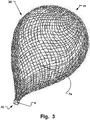
- 3 and 4 corresponding ball wire meshes are used with a proximal socket.
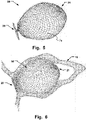
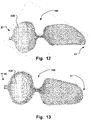
- Figures 5 and 6 show a form of the self-expandable occlusion device according to the invention without a socket, consisting of a braid, as described above, braided from a piece of wire to form a spherical structure 7 and with a forming and / or heat treatment process in the desired final shape.
- the occlusion device 1 is an auricle occluder with a shape consisting of a front proximal retention area 2, a middle area 5 and a rear, spherical distal retention area 3.
- the ends of the wires or threads of the braiding 7 run into the proximal retention area 2 a socket 4 together.
- the distal retention area 3, on the other hand, has a closed end without a mount in the preferred form.
- the occlusion device Due to the shape similar to a strawberry, the occlusion device is also called "Strawberry Occluder”.
- the mesh 7 is formed from wires or threads, which preferably consist of nitinol or another material with a shape memory or memory effect. It would be conceivable here to use a polymer plastic that has the shape memory property. It is also conceivable to use a biodegradable shape memory material. It is essential that the mesh 7 has sufficient flexibility so that the occlusion device 1 can be tapered to the diameter of a catheter (not explicitly shown) used in a minimally invasive, in particular intravascular surgical intervention. Due to the memory effect of the material, the occlusion device 1 tapered in this way has a shape memory function, so that the device 1 expands automatically after leaving the catheter and resumes a predetermined shape corresponding to the use. This usually takes place after the occlusion device 1, which is initially arranged in the catheter, has been placed at the site to be treated, in particular in the atrial appendage of a patient's heart.
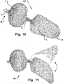
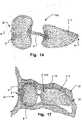
- Figures 15 and 16 represent a variant of the heart ear occluder according to the invention 1 and 2 and can definitely find their application due to the high range of variation and specificity of the auricle, as in 24 shown.
- the occlusion device is shown in its expanded state.
- the occlusion device 1 has a proximal retention area 2 , a distal retention area 3 and a waisted, cylindrical central area 5 .
- the auricular appendage occluder has a proximal end 20 and a distal end 21 .
- the distal retention area 3 with the spherical area 6 formed thereon serves primarily to attach and hold the implanted and expanded occlusion device 1 in the atrial appendage of a patient.
- the spherical area 6 in the atrial appendage to be closed comes to rest against the inner walls of the auricle and forms a non-positive connection with the inner walls of the auricular appendage and thus holds the implanted and expanded occlusion device 1 in the auricular appendage. It would be conceivable, for example, for the distal retention area 3 or the spherical area 6 to be under radial pretension, so that the secure hold of the expanded occlusion device 1 can be guaranteed for a relatively wide range of atrial appendage openings.
- the proximal retention area 2 serves to close the opening of the atrial appendage as optimally as possible.
- the details of the functioning of the individual retention areas are made with reference to the 2 and 6 discussed in more detail below.
- the construction of the occlusion device 1 is based on the principle that the occlusion device 1 can be tapered to the size of a catheter. After exiting the catheter, the retention areas 3, 2 then unfold independently and lie against the inner walls of the atrial appendage.
- the construction according to the invention is thus a somewhat self-positioning and self-centering system.
- the central area 5 has a length that is predetermined for the application in order to ensure that the atrial appendage opening is closed.
- the instrument 1 Due to the flexible property of the occlusion device 1 due to the materials used and due to the mesh 7, the instrument 1 is designed to be reversibly folded and unfolded, so that an already expanded occlusion device 1 can be folded together, for example with the aid of an explantation catheter, with the non-positive connection between the ball area 6 and the inner walls of the atrial appendage 10 are then released.
- the occlusion device 1 in the implanted state.
- the occlusion device is inserted in the left atrial appendage 10 of a patient's heart and is used to close the atrial appendage.
- the spherical area 6 of the distal retention area 3 rests against the inner walls of the atrial appendage 10 and is used to position and fix the implanted occlusion device 1.
- the proximal retention area 2 closes with the opening of the atrial appendage 10, with the periphery of the distal retention area comes to rest against the wall 12 of the atrial appendage opening, while the central region 5 passes through the opening 11.
- the occlusion device 1 therefore represents a closure system that is introduced into a patient's body and positioned at the location intended for this purpose using minimally invasive methods, ie for example via a catheter and guide wires.
- the proximal retention area 2 of the instrument 1 is designed in such a way that no material of the implanted occlusion device 1 can get into the patient's bloodstream via the atrial appendage wall.
- the edge of the proximal retention area 2 ends flush with the atrial appendage wall 13 . This occurs over a relatively wide range, independent of atrial appendage diameter and strength Auricular appendage wall 12 at the atrial appendage opening 11. This can ensure that complete endothelialization occurs relatively quickly after the implantation of the occlusion device 1 and possible defense reactions from the patient's body do not occur, since blood contact with the material of the implant 1 is effectively prevented.
- FIG. 3 shows a spherical hollow ball braid 30 made of threads 7a for the production of an auricle occluder.
- FIG 5 is shown in a side view of an auricular ear occluder 50 without a mount.
- the cardiac appendage occluder 50 does not have a socket at the proximal end.
- 6 is the shape of the heart ear occluder 50 after figure 5 shown following implantation in the left atrial appendage 10 of the left atrium.
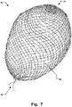
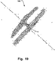
- FIG. 7 illustrates a ball mesh 70 from a piece of wire without a socket.
- FIG. 15 shows an embodiment of an atrial auricular occluder 150 according to the invention with a flat double disc at the proximal end 20 and an intermediate retention area 151.
- the embodiment is shown following implantation in the left atrial appendage 10 .
- a distal retention area is designed with a spherical shape in such a way that it curves outwards when the occlusion device expands in order to come into contact with the inner walls of the atrial appendage in the implanted state.
- the proximal retention area which is advantageously designed as a proximal umbrella, for example, is then unfolded and positioned, i.e.
- the distal area of the occlusion device i.e. the distal spherical umbrella
- the distal retention area of the occlusion device is pulled further into the atrial appendage and a tensile force is thus exerted on the proximal umbrella via the central area.
- the proximal umbrella or the proximal retention area is kept under permanent tension at the entrance of the atrial appendage.
- a self-positioning and self-retaining occlusion device is specified, with the position of the proximal umbrella preferably being held flush with the opening of the atrial appendage with the aid of the distal spherical umbrella, which automatically curves outwards.
- the occlusion device used can be completely enclosed by the body's own tissue much more quickly than with the closure systems known from the prior art.
- a mesh made up of thin wires or threads as the starting material for the occlusion device according to the invention results in the further advantage that it has long-term mechanical stability. As already indicated, the occurrence of fractures in the structure or other types of material fatigue in the implant used can be largely prevented. Furthermore, the mesh has sufficient rigidity.
- any mounts can be dispensed with; this applies to both the proximal and the distal end of the occlusion device.
- a special ball mesh was used, which is made from just one wire.
- the basis is the processes of 2D and 3D braiding known in the literature, in which case the braiding spindles are arranged on a flat surface like a chess board and such braided structures can be produced with any changes in direction.
- Another possibility for manufacturing such spherical meshes has already been described in the Occlutech patent application Germany No. DE102006013770.1 Ball occluder described. With this invention it is possible to intertwine individual wire sections to create ball occluders with a socket.
- DE102006013770.1 is hereby incorporated by reference in its entirety.
- spherical braids can be produced without sockets.
- the two remaining wire ends are connected to each other, for example welded, so that a closed spherical network is formed.
- a mount can ultimately be dispensed with both distally and proximally.
- the big advantage of such a Atrial appendage occluder is, for example, that the proximal end of the occluder, which is placed in the left atrial appendage, does not have a socket element, so that the formation of possible trombs can be extremely reduced.
- the wire ends of one wire can be brought together at the proximal end of the heart ear occluder or at another position.
- a particularly preferred embodiment provides that the mesh is formed from a shape-memory material, in particular nitinol or plastic.
- nitinol in occlusion devices.
- Shape memory polymers belong to the group of smart polymers and are polymers that exhibit a shape memory effect, i.e. are able to change their external shape under the influence of an external stimulus such as a change in temperature.
- the polymer is first brought into its permanent shape using conventional processing methods such as injection molding or extrusion.
- the plastic is then deformed and fixed in the desired temporary shape, which is also called "programming".
- this process can be carried out in such a way that the sample is heated, deformed and then cooled.
- the polymer or plastic can also be deformed at low temperature, which is referred to as "cold stretching”.
- the permanent shape is thus stored while the temporary shape is currently available. If the polymer molding is now heated to a temperature higher than the switching temperature, the shape memory effect is triggered and the stored permanent shape is thus restored.
- the temporary shape cannot be reversed when the sample cools down, which is why one speaks of a so-called one-way shape memory effect.
- shape memory polymers are many times superior in terms of their memory performance. Only a small amount of effort (heating or cooling) is required to program the temporary shape or to restore the permanent shape. In addition, with Nitinol, the maximum deformation between permanent and temporary shape is only 8%. Shape memory polymers have significantly higher deformability of up to 1,100%. All of the aforementioned shape memory polymers and materials are claimed with the present invention for the biomedical application of the occlusion device according to the invention.
- the material has a biodegradable shape-memory polymer material.
- biodegradable implant materials are particularly suitable. Such degradable materials or polymers contain cleavable bonds under physiological conditions. This is referred to as "biodegradability" when the material is degraded by or in a biological system with a loss of mechanical properties. The external shape and mass of the implant may be retained during degradation. If a degradation time is mentioned without additional quantifying information, then what is meant is the time in which the complete loss of mechanical properties occurs.
- Biostable materials are those that are stable in biological systems and are at least only partially degraded in the long term.
- hydrolytic degradation is that the rate of degradation is independent of the site of implantation, since water is present everywhere. In contrast, the concentration of enzymes varies greatly locally. In the case of biodegradable polymers or materials, degradation can therefore take place through pure hydrolysis, enzymatically induced reactions or through a combination of these. Typical hydrolyzable chemical bonds are amide, ester or acetal bonds. Two mechanisms are observed during degradation. In surface degradation, the hydrolysis of chemical bonds takes place exclusively on the surface. Due to the hydrophobic character, polymer construction occurs faster than the diffusion of water into the interior of the material.
- the threads 7a of the braid 7 consist of a shape-memory polymer composition, so that the braid 7 deforms from a temporary shape to a permanent shape under the influence of an external stimulus, the temporary shape in the first shaping of the braid 7 and the permanent shape in the second shaping of the braid 7 is present.
- the external stimulus can be a definable switching temperature, for example in the range between room temperature and the body temperature of a patient.
- the polymer composition of certain embodiments has polymeric switching elements, with the temporary shape of the mesh 7 being stabilized below the definable switching temperature with the aid of characteristic phase transitions of the polymeric switching elements.
- the polymer composition has a crystalline or partially crystalline polymer network with crystalline switching segments, the temporary shape of the mesh 7 being fixed and stabilized by freezing the crystalline switching segments during the crystallization transition, the switching temperature being determined by the crystallization temperature or switching temperature of the crystalline switching segments .
- the polymer composition has an amorphous polymer network with amorphous switching segments, the temporary shape of the mesh 7 being fixed and stabilized by freezing the amorphous switching segments at the glass transition of the switching segments, the switching temperature being determined by the glass transition temperature of the amorphous switching segments.
- the polymer composition has a linear, phase-segregated multiblock copolymer network, which can be present in at least two different phases, the first phase being a hard-segment-forming phase in which a large number of hard-segment-forming blocks are formed in the polymer, which serve for the physical crosslinking of the polymer structure and determine and stabilize the permanent shape of the braid 7, and wherein the second phase is a switching segment-forming phase in which a large number of switching segment-forming blocks are formed in the polymer, which are used to fix the temporary shape of the Braid 7 are used, the transition temperature of the switching segment-forming phase to the hard segment-forming phase being the switching temperature, and above the transition temperature of the hard segment-forming phase the shaping of the braid 7 by conventional methods, in particular by injection molding or extrusion proceed, can be adjusted.
- the first phase being a hard-segment-forming phase in which a large number of hard-segment-forming blocks are formed in the polymer, which serve for the physical crosslinking of
- the polymer composition can have thermoplastic polyurethane elastomers with a multiblock structure, the hard segment-forming phase being formed by reacting diisocyanates, in particular methylenebis(4-phenylisocyanate) or hexamethylene diisocyanate, with diols, in particular 1,4-butanediol, and wherein the switching segment-forming phase of oligomeric polyether or.
- Polyester diols in particular starting from OH-terminated poly(tetrahydrofuran), poly( ⁇ -caprolacetone), poly(ethylene adipate), poly(ethylene glycol) or poly(propylene glycol).
- the polymer composition can also have phase-segregated diblock copolymers with an amorphous A block and a semi-crystalline B block, the glass transition from the amorphous A block forming the hard segment-forming phase, and the melting temperature of the semi-crystalline B block as the switching temperature for the thermal shape memory -Effect serves.
- the polymer composition can have polystyrene as the amorphous A block and poly(1,4-butadiene) as the partially crystalline B block.
- the polymer composition has a phase-segregated triblock copolymer with a partially crystalline central B block and with two amorphous terminal A blocks, with the A blocks building up the hard segment and with the B block determining the switching temperature.
- the polymer composition can have, for example, partially crystalline poly(tetrahydrofuran) as the central B block and amorphous poly(2-methyloxazoline) as the terminal A blocks.
- the polymer composition comprises polynorbornene, polyethylene-nylon-6 graft copolymers and/or crosslinked poly(ethylene-co-vinyl acetate) copolymers.
- the polymer composition has a covalent crosslinked polymer network, which is built up by polymerization, polycondensation and/or polyaddition of difunctional monomers or macromers with the addition of trifunctional or higher functional crosslinkers, with a suitable selection of the monomers, their functionality and the proportion the chemical, thermal and mechanical properties of the polymer network formed can be specifically adjusted on the crosslinker.
- the polymer composition can be, for example, a covalent polymer network, which is constructed by crosslinking copolymerization of stearyl acrylate and methacrylic acid with N,N'-methylenebisacrylamide as a crosslinker, the shape memory effect of Polymer composition is based on crystallizing stearyl side chains.
- the polymer composition has a covalently crosslinked polymer network, which is formed by subsequent crosslinking of linear or branched polymers.
- Crosslinking can be triggered by ionizing radiation or by thermal cleavage of radical-forming groups.
- the polymer composition has at least one biodegradable material.
- the polymer composition can have, for example, a hydrolytically degradable polymer, in particular poly(hydroxycarboxylic acids) or corresponding copolymers.
- the polymer composition has, for example, enzymatically degradable polymers.
- the polymer composition has a biodegradable thermoplastic amorphous polyurethane copolyester polymer network.
- the polymer composition can have a biodegradable, elastic polymer network, which is obtained by crosslinking oligomeric diols with diisocyanate. In this case, the polymer composition can be formed on the basis of covalent networks starting from oligo( ⁇ -caprolactone) dimethacrylate and butyl acrylate.
- the advantage of this embodiment can be seen in the fact that the catheter systems to be used for implantation and explantation can have a significantly reduced inner diameter, which significantly increases the maneuverability of the occlusion device to be implanted. Hence, the positioning accuracy of the instrument in the atrial appendage can be improved.
- the inner diameter of the catheter used for implantation or explantation is between 8 and 10 French, whereas when using occlusion devices made of polymer plastic, the inner diameter only has to be between 6 and 8 French.
- the occlusion device has at least one fabric insert 120, 130, which is arranged in or on the proximal retention area for the complete closure of the atrial appendage.
- This tissue insert serves to seal the interstices remaining in the expanding diameters of the occlusion device after the device has been inserted and expanded in the atrial appendage.
- the fabric insert is fastened, for example, to the mesh of the occlusion device at the distal retention area in such a way that it can be stretched over the distal retention area like a cloth.
- the fabric inserts can be made of Dacron (polyethylene terephthalate), for example.
- Dacron polyethylene terephthalate
- other materials and other positions of the tissue insert in or on the occlusion device are also conceivable here, including biodegradable materials, which have been described above.
- the occluder according to the invention is a self-expandable instrument, which can be implanted in a particularly simple manner using, for example, a suitable insertion catheter.
- a vein is punctured in the patient's groin and the insertion catheter system is advanced up to the septum of the right atrium.
- the left atrium of the heart is reached by means of a puncture of the septum of the atrium, which can be a known transseptal puncture, for example, so that the insertion catheter system can then be introduced into the left atrial appendage from the groin vein.
- the self-expanding occlusion device for closing the atrial appendage can then be inserted via the insertion catheter system; the corresponding locks have a relatively small cross-section, a maximum of 9 to 10 F.
- the occlusion device which is in the folded state during implantation, preferably has a diameter of 6 to 10 French, so that the procedure for closing the atrial appendage is minimally invasive.
- the occlusion device After the folded occlusion device is positioned in the atrial appendage to be occluded using, for example, the delivery catheter, the occlusion device is released from the catheter, whereupon it unfolds due to its self-expanding nature and assumes the pronounced shape by means of the forming and heat treatment process used during manufacture.
- the rear distal retention area with the ball area formed on it In this expanded state, the rear distal retention area with the ball area formed on it is completely unfolded and comes to rest on the inner walls of the atrial appendage to be closed.
- the distal retention area with the spherical area formed thereon is used for fastening and positioning the expanded occlusion device in the atrial appendage.
- the middle area extending from the distal retention area in the direction of the atrial appendage and the proximal retention area provided at the proximal end of the middle area fill the opening area of the auricular appendage almost completely, so that the entire expanded occlusion device when inserted serves as a closure plug for closing the auricular appendage.
- trombus formation with the risk of a stroke can be significantly reduced.
- the occlusion device can do without attachment hooks or other anchoring means, which are usually used in such occlusion devices for fixing and positioning the instrument in the tissue be used. It should be noted in particular that due to the extremely thin-walled design of the tissue in the vicinity of the atrial appendage, the fastening hooks usually used cannot provide permanent fastening and positioning of the occlusion device.
- a spherical hollow braid is formed using a circular braiding machine, for example.
- a technique can be used here in which the formed braid is bundled at the end of the braid length, i.e. at the later distal end of the occlusion device, and remains closed at the beginning of the braid length, i.e. at the later distal end of the occlusion device. This makes it possible to produce a spherical hollow braid whose bundled end corresponds to the proximal end of the finished occlusion device and whose opposite closed end corresponds to the distal end of the finished occlusion device.
- the manufactured occlusion device Since a braiding process known per se can be used to manufacture the occlusion device, the manufactured occlusion device has mechanical properties with regard to, for example, expansion, stability, strength, etc., which can be individually adapted to the subsequent use of the occlusion device.
- Metallic wires, but also organic threads, can advantageously be processed into the mesh.
- Ball braids as described, can also be used without a socket.
- the method step of shaping the retention areas and the central area has a reshaping and/or heat treatment step.
- the formed spherical hollow mesh consists of nitinol or another material, in particular polymer, with a shape memory or memory effect.
- the mesh is formed from a shape-memory polymer, which is based, for example, on polyanhydrides as a matrix or on polyhydroxycarboxylic acid. These are synthetic degradable materials that have a thermally induced shape memory effect.
- shape-memory polymers such as block copolymers such as those used in Offprint applied chemistry 2002, 114, pages 2138 to 2162 by A. Lendlein and S. Kelch to be discribed.
- Such materials can be brought into a corresponding final shape in a simple manner by a combination of forming and heat treatment steps.
- a finished occluder can then be reduced to the size of a catheter, for example.
- the occlusion device unfolds automatically and resumes the shape that was given to the spherical or funnel-shaped hollow mesh of the occlusion device during the manufacturing process by means of the reshaping and/or heat treatment step.
- the spherical hollow braid is preferably produced in such a way that thin wires or threads, which make up the finished braid, are intertwined when the spherical hollow braid is formed at the distal end of the braid.
- other manufacturing processes are also conceivable.
Description
Die vorliegende Erfindung betrifft ein selbst expandierbares Occlusionsinstrument zum Verschließen eines Herzohres, bestehend aus einem Geflecht dünner Drähte, oder Fäden, welches mittels eines Formgebungs-, Umformungs- und/oder Wärmebehandlungsverfahrens eine geeignete Formgebung erhält, wobei das Occlusionsinstrument einen vorderseitigen proximalen Retentionsbereich und einen rückseitigen distalen Retentionsbereich aufweist, und wobei in dem proximalen Retentionsbereich die Enden der Drähte oder Fäden in einer Fassung aber auch in einer zweiten Lösung ohne Fassung zusammenlaufen. Des Weiteren weist das Occlusionsinstrument einen Mittenbereich zwischen dem proximalen und dem distalen Retentionsbereich auf. Das Occlusionsinstrument ist dabei so ausgeführt, dass es in einem zusammengefalteten Zustand mittels eines Katheters in den Körper eines Patienten minimal-invasiv einführbar und in dem Herzohr des Patienten positionierbar ist. Des Weiteren betrifft die Erfindung Verfahren zur Herstellung eines solchen Occlusionsinstruments.The present invention relates to a self-expandable occlusion device for closing an atrial appendage, consisting of a network of thin wires or threads, which is given a suitable shape by means of a shaping, forming and/or heat treatment process, the occlusion device having a front proximal retention area and a rear having distal retention area, and wherein in the proximal retention area the ends of the wires or threads converge in one version but also in a second solution without version. Furthermore, the occlusion device has a middle area between the proximal and the distal retention area. The occlusion device is designed in such a way that, in a folded state, it can be inserted into a patient's body in a minimally invasive manner by means of a catheter and can be positioned in the patient's atrial appendage. Furthermore, the invention relates to methods for producing such an occlusion device.
Ein derartiges Occlusionsinstrument ist zumindest teilweise dem Prinzip nach aus der Medizintechnik bekannt. Beispielsweise ist in der
Ähnliche Instrumente sind in der Occlutech-Patentanmeldung
Wenn der Patient unter einem so genannten Vorhofflimmern des Herzens leidet, treten besondere emboliebedingte Probleme in Erscheinung. Hierbei handelt es sich um eine frequente Erregung der Vorhöfe des Herzens, die zu keiner Kontraktion der Vorhöfe führt. Folge dieses Kontraktionsverlustes der Vorkammern des Herzens ist es, dass eine wirksame Durchwirbelung und Durchmischung des Blutes ausbleibt und sich Tromben im Vorhof bilden können. Ein erhebliches Risiko bei der Vorhoftrombenbildung infolge Vorhofflimmerns besteht darin, dass solche Tromben mit dem Blutstrom mitgerissen werden können und in die arterielle Zirkulation gelangen. Folgen dieser Embolisation sind insbesondere Schlaganfälle, die in etwa 5% pro Jahr bei Patienten mit Vorhofflimmern auftreten, falls nicht durch eine chronische Behandlung eine Geringungshemmung des Blutes mit so genannten Dicumerolen durchgeführt wird. Eine Herbeiführung der Geringungshemmung des Blutes mit so genannten Dicumerolen ist allerdings ebenfalls nicht risikolos. Nebenwirkungen der Behandlungen mit Dicumerolen sind vermehrte Blutungen, sodass Kontraindikationen für diese Behandlung bei ca. 20% der Patienten mit Vorhofflimmern besteht und die Patienten somit aufgrund von einer Risikoabwägung Blutung/Schlaganfall das Risiko eines Schlaganfalls in Kauf genommen wird.If the patient suffers from a so-called atrial fibrillation of the heart, special embolism-related problems appear. This is a frequent excitation of the atria of the heart, which does not lead to any contraction of the atria. The result of this loss of contraction of the atria of the heart is that there is no effective turbulence and mixing of the blood and thrombi can form in the atrium. A significant risk of atrial thrombus formation as a result of atrial fibrillation is that such thrombi can become entrained in the bloodstream and enter the arterial circulation. Consequences of this embolization are, in particular, strokes, which occur in about 5% per year in patients with atrial fibrillation, unless the blood is inhibited by chronic treatment with so-called dicumerols. However, bringing about the inhibition of blood clotting with so-called dicumerols is also not without risk. Side effects of treatments with dicumerols are increased bleeding, so that there are contraindications for this treatment in about 20% of patients with atrial fibrillation and the patients are therefore accepted the risk of a stroke due to a risk assessment of bleeding/stroke.
Tromben im Vorhof des Herzens entstehen in überwiegender Mehrzahl in den so genannten Herzohren. Die Herzohren sind Ausstülpungen an den Vorhöfen des menschlichen Herzens. Das rechte Herzohr liegt neben der aufsteigenden Aorta, und das linke Herzohr neben der großen Lungenarterie. Dabei ist das linke Herzohr bei Patienten mit Vorhofflimmern der häufige Entstehungsort für Blutgerinnsel, die zu einem Schlaganfall führen können.Trombes in the atrium of the heart arise in the overwhelming majority in the so-called auricles. The auricles are protuberances on the atria of the human heart. The right atrial appendage lies adjacent to the ascending aorta, and the left atrial appendage lies adjacent to the large pulmonary artery. The left atrial appendage is the most common site of blood clots in patients with atrial fibrillation, which can lead to a stroke.
Aufgrund der im Zusammenhang mit der zuvor beschriebenen Vorhoftrombenbildung genannten Risiken und Probleme liegt der vorliegenden Erfindung die Aufgabe zugrunde, ein Occlusionsinstrument anzugeben, mit dem das Herzohr des linken Vorhofs verschlossen werden kann, um eine Trombusbildung mit dem Risiko eines Schlaganfalls erheblich zu reduzieren. Insbesondere soll ein Occlusionsinstrument angegeben werden, mit dem das Schlaganfallrisiko auch bei solchen Patienten reduziert werden kann, bei denen eine Gerinnungshemmung mit Dicumerolen (so genannte Antikoagulation) aufgrund von Blutungsneigungen kontra indiziert ist. Ebenso sollte das Occlusionsinstrument sicher im Herzohr zu verankern sein, ohne sich zu lösen.Due to the risks and problems mentioned in connection with the atrial thrombus formation described above, the present invention is based on the object of specifying an occlusion device with which the atrial appendage of the left atrium can be closed in order to significantly reduce thrombus formation with the risk of a stroke. In particular, an occlusion device is to be specified with which the risk of a stroke can also be reduced in those patients in whom anticoagulation with dicumerols (so-called anticoagulation) is contraindicated due to bleeding tendencies. Likewise, the occlusion device should be able to be securely anchored in the atrial appendage without becoming loose.
Nach dem Stand der Technik existieren verschiedene Lösungen, welche im Wesentlichen Teilgeflechte mit gestängeartigen Bauelementen kombinieren, teilweise werden dabei auch gelaserte Konstruktionen in dieser Kombination eingesetzt, das betrifft solche Erfindungen wie:
Diese Erfindungen haben unter anderem den Nachteil, dass für die Implantation relativ große Einführschleusen mit bis zu 14 F Innendurchmesser benötigt werden.One of the disadvantages of these inventions is that relatively large insertion sheaths with an internal diameter of up to 14 F are required for the implantation.
Weitere Erfindungen wie von Amplatz
Eine weitere Anmeldung von Occlutech betrifft die Erfindung eines einnabigen Herzohroccluders unter Verwendung eines Fixiermittels zum Ausbilden einer kraftschlüssigen Verbindung zwischen dem Geflecht eines Occlusionskörpers und der Herzohrwandung,
Aufgabe der Erfindung ist es, die oben genannten Nachteile der herkömmlichen Verfahren und Vorrichtungen zu überwinden und eventuell eine möglichst Kosten senkende und patientenfreundliche sowie pateintensichere Lösung anzugeben.The object of the invention is to overcome the above-mentioned disadvantages of the conventional methods and devices and possibly to specify a solution that reduces costs and is patient-friendly and patient-safe as far as possible.
Die oben genannte Aufgabe wird mit einem selbst expandierbaren Occlusionsinstrument zum Verschließen eines Herzohres gelöst, wobei das Occlusionsinstrument aus einem Geflecht dünner Drähte, Litzen oder Fäden besteht, welches mittels eines Formgebungs-, Umformungs- und/oder Wärmebehandlungsverfahrens eine geeignete Formgebung erhalten hat gemäß Anspruch 1The above-mentioned object is achieved with a self-expanding occlusion device for closing an auricular appendage, the occlusion device consisting of a network of thin wires, strands or threads, which has been given a suitable shape by means of a shaping, forming and/or heat treatment process according to
Bevorzugte Weiterentwicklungen der Erfindung bezüglich des Occlusionsinstruments sind in den Unteransprüchen angegeben.Preferred further developments of the invention with regard to the occlusion device are specified in the dependent claims.
Im Folgenden werden bevorzugte Ausführungsbeispiele des erfindungsgemäßen Occlusionsinstruments anhand der Zeichnungen näher erläutert. Es zeigen:
-
Fig. 1 Eine Seitenansicht eines Herzohroccluders mit einer Fassung; -
Fig. 2 Der Herzohroccluders nachFig. 1 nach Implantation im linken Herzohr (Englisch Left Atrial Appendage - LAA), angrenzend zum linken Vorhof; -
Fig. 3 ,4 Kugelgeflecht, kugel- und ballonförmig zur Herstellung eines Herzohroccluders nachFig. 1 ; -
Fig. 5 Eine Seitenansicht eines Herzohroccluders ohne Fassung; -
Fig. 6 Die Form nachFig. 5 im Anschluss an eine Implantation im linken Herzohr des linken Vorhofes; -
Fig. 7 Kugelgeflecht aus einem Drahtstück ohne Fassung; -
Fig. 8-14 : gelöscht -
Fig. 15 Fünfte Variante einer Ausführungsform eines Herzohroccluders mit einer flachen Doppelscheibe am proximalen Ende; -
Fig. 16 Die Ausführungsform nach der fünften Variante im Anschluss der Implantation in das linke Herzohr; -
Fig. 17-23 : gelöscht. -
Fig. 24 Darstellung eines Herzohres.
-
1 A side view of a cardiac ear occluder with a socket; -
2 The heart ear occluders after1 after implantation in the left atrial appendage (LAA), adjacent to the left atrium; -
3 ,4 Spherical braid, spherical and balloon-shaped for the production of acardiac ear occluder 1 ; -
figure 5 A side view of a heart ear occluder without a socket; -
6 The shape afterfigure 5 following an implantation in the left atrial appendage of the left atrium; -
7 Ball mesh made from a piece of wire without socket; -
Figures 8-14 : turned off -
15 Fifth variant of an embodiment of an auricle occluder with a flat double disc at the proximal end; -
16 The embodiment according to the fifth variant following the implantation in the left atrial appendage; -
17-23 : turned off. -
24 Depiction of a heart appendage.
Während die Erfindung nachstehend in einer Ausführungsform zum Durchführen der Erfindung beschrieben werden wird, versteht der Fachmann, dass diese Ausführungsform nur einen illustrative, nicht begrenzende Beispiel von vielfältigen Formen, welche die vorliegende Erfindung einnehmen kann, darstellt.While the invention will hereinafter be described in terms of an embodiment for carrying out the invention, those skilled in the art will understand that this embodiment is merely an illustrative, non-limiting example of the various forms that the present invention may take.
Selbstverständlich sind hier aber auch andere, wie auch immer geartete und anwendungsspezifische Formgebungen des Occlusionsinstrumtents denkbar. Die hier dargestellte Formgebung dient lediglich zur Beschreibung von einer bevorzugte Ausführungsform des Occlusionsinstruments und soll insbesondere nicht den Schutzumfang der Erfindung in irgendeiner Weise einschränken.Of course, other shapes of the occlusion instrument, of whatever type and application-specific, are also conceivable here. The shape shown here only serves to describe a preferred embodiment of the occlusion device and is not intended in any way to limit the scope of protection of the invention.
Das nicht erfindungsgemäße Occlusionsinstrument 1 der in
Bei dem Occlusionsinstrument 1 handelt es sich um einen Herzohroccluder mit einer Formgebung bestehend aus einem vorderseitigen proximalen Retentionsbereich 2, einem Mittenbereich 5 und einem rückseitigen, kugelförmigen distalen Retentionsbereich 3. In dem proximalen Retentionsbereich 2 laufen die Enden der Drähte bzw. Fäden des Geflechts 7 in einer Fassung 4 zusammen. Der distale Retentionsbereich 3 hingegen weist in der bevorzugten Form ein geschlossenes Ende ohne Fassung aus.The
Aufgrund der Form ähnlich einer Erdbeere wird das Occlusionsinstrument auch "Strawberry-Occluder" genannt.Due to the shape similar to a strawberry, the occlusion device is also called "Strawberry Occluder".
Das Geflecht 7 ist aus Drähten oder Fäden gebildet, welche in bevorzugter Weise aus Nitinol oder aus einem anderen Material mit Formgedächtnis oder Memory-Effekt bestehen. Denkbar hierbei wäre es, ein Polymerkunststoff einzusetzen, der die Formgedächtniseigenschaft aufweist. Auch ist es denkbar, ein biologisch abbaubares Formgedächtnismaterial zu verwenden. Wesentlich ist, dass das Geflecht 7 eine ausreichende Flexibilität aufweist, sodass das Occlusionsinstrument 1 auf den Durchmesser eines bei einem minimal-invasiven, insbesondere intravaskulären Operationseingriff verwendeten (nicht explizit dargestellten) Katheters verjüngt werden kann. Aufgrund des Memory-Effekts des Materials verfügt das derart verjüngte Occlusionsinstrument 1 eine Formgedächtnisfunktion, sodass sich das Instrument 1 nach dem Verlassen des Katheters selbstständig expandiert und eine der Verwendung entsprechende, vorbestimmte Form wieder einnimmt. Üblicherweise erfolgt dies, nachdem das zunächst im Katheter angeordnete Occlusionsinstrument 1 an der zu behandelnden Stelle, insbesondere im Herzohr des Herzens eines Patienten, platziert wurde.The mesh 7 is formed from wires or threads, which preferably consist of nitinol or another material with a shape memory or memory effect. It would be conceivable here to use a polymer plastic that has the shape memory property. It is also conceivable to use a biodegradable shape memory material. It is essential that the mesh 7 has sufficient flexibility so that the
In den
Im implantierten und expandierten Zustand dient der proximale Retentionsbereich 2 dazu, die Öffnung des Herzohres möglichst optimal zu verschließen. Auf die Einzelheiten der Funktionsweise der einzelnen Retentionsbereiche wird unter Bezugnahme auf die
Der Konstruktion des Occlusionsinstruments 1 liegt das Prinzip zugrunde, dass sich das Occlusionsinstrument 1 auf die Größe eines Katheters verjüngen lässt. Nach dem Austritt aus dem Katheter entfalten sich dann die Retentionsbereiche 3, 2 selbstständig und legen sich an die Innenwandungen des Herzohres an. Bei der erfindungsgemäßen Konstruktion handelt es sich somit um ein in gewissen Maßen selbstpositionierendes und selbstzentrierendes System. Der Mittenbereich 5 hat dabei eine für die Anwendung vorab festgelegte Länge, um das Verschließen der Herzohröffnung zu gewährleisten.The construction of the
Durch die flexible Eigenschaft des Occlusionsinstruments 1 aufgrund der verwendeten Materialien und aufgrund des Geflechtes 7 ist das Instrument 1 reversibel zusammen- und auseinanderfaltbar ausgeführt, sodass ein bereits expandiertes Occlusionsinstrument 1 beispielsweise mithilfe eines Explantations- Katheters zusammenfaltbar ist, wobei die kraftschüssige Verbindung zwischen dem Kugelbereich 6 und den Innenwandungen des Herzohres 10 dann gelöst werden.Due to the flexible property of the
In
So ist in bevorzugter Weise für das Occlusionsinstrument vorgesehen, dass ein distaler Retentionsbereich mit einer Kugelform derart ausgelegt ist, dass er sich beim Expandieren des Occlusionsinstruments nach außen wölbt, um derart im implantierten Zustand mit den Innenwandungen des Herzohres zur Anlage zu kommen. Mit dieser bevorzugten Ausführungsform ist es demnach möglich, dass das erfindungsgemäße selbst expandierbare Occlusionsinstrument mittels eines Einführ-Kathetersystems besonders tief in das zu verschließende Herzohr vorgeschoben werden kann. Der proximale Retentionsbereich, der in vorteilhafter Weise beispielsweise als proximales Schirmchen ausgebildet ist, wird anschließend, das heißt, nachdem das Occlusionsinstrument mithilfe des Kathetersystems in dem zu verschließenden Herzohr eingeschoben worden ist, zur Entfaltung gebracht und positioniert, wobei das Schirmchen am Rand der Öffnung des Herzohres zum Eingang des Herzohres anliegt. Gleichzeitig expandiert sich auch der distale Bereich des Occlusionsinstruments, das heißt der distale Kugelschirm, wobei beim Expansionsvorgang des distalen Kugelschirmchens der distale Retentionsbereich des Occlusionsinstruments weiter in das Herzohr hineingezogen wird und so über den Mittenbereich eine Zugkraft auf das proximale Schirmchen ausgeübt wird. Als eine direkte Folge hiervon wird das proximale Schirmchen bzw. der proximale Retentionsbereich unter einer permanenten Spannung am Eingang des Herzohres gehalten. Anders ausgedrückt bedeutet dies, dass mit der vorteilhaften Weiterentwicklung des selbst expandierbaren Occlusionsinstruments ein selbstpositionierendes und selbsthaltendes Occlusionsinstrument angegeben wird, wobei die Position des proximalen Schirmchens vorzugsweise bündig an der Öffnung des Herzohres mithilfe des sich selbstständig nach außen wölbenden distalen Kugelschirmchens gehalten wird.It is preferably provided for the occlusion device that a distal retention area is designed with a spherical shape in such a way that it curves outwards when the occlusion device expands in order to come into contact with the inner walls of the atrial appendage in the implanted state. With this preferred embodiment, it is therefore possible for the self-expandable occlusion device according to the invention to be advanced particularly deeply into the atrial appendage to be occluded by means of an insertion catheter system. The proximal retention area, which is advantageously designed as a proximal umbrella, for example, is then unfolded and positioned, i.e. after the occlusion device has been pushed into the atrial appendage to be occluded with the help of the catheter system, with the umbrella at the edge of the opening of the atrial appendage to the entrance of the atrial appendage. At the same time, the distal area of the occlusion device, i.e. the distal spherical umbrella, expands, whereby during the expansion process of the distal spherical umbrella, the distal retention area of the occlusion device is pulled further into the atrial appendage and a tensile force is thus exerted on the proximal umbrella via the central area. As a direct consequence of this, the proximal umbrella or the proximal retention area is kept under permanent tension at the entrance of the atrial appendage. In other words, this means that with the advantageous further development of the self-expanding occlusion device, a self-positioning and self-retaining occlusion device is specified, with the position of the proximal umbrella preferably being held flush with the opening of the atrial appendage with the aid of the distal spherical umbrella, which automatically curves outwards.
Durch das einerseits flexible und andererseits kraftschlüssige Anliegen des Kugelbereiches mit einer relativ großen Oberfläche an der Innenwandung des Herzohres kann ferner erreicht werden, dass das eingesetzte Occlusionsinstrument deutlich schneller als bei den aus dem Stand der Technik bekannten Verschlusssystemen vollständig von körpereigenem Gewebe eingeschlossen werden kann.Due to the on the one hand flexible and on the other hand non-positive contact of the spherical area with a relatively large surface area on the inner wall of the atrial appendage, it can also be achieved that the occlusion device used can be completely enclosed by the body's own tissue much more quickly than with the closure systems known from the prior art.
Aus der Verwendung eines aus dünnen Drähten oder Fäden aufgebauten Geflechts als Ausgangsmaterial für das erfindungsgemäße Occlusionsinstrument leitet sich der weitere Vorteil ab, dass es eine langfristige mechanische Stabilität aufweist. Wie bereits angedeutet, kann das Auftreten von Brüchen in der Struktur oder anders artige Materialermüdung des eingesetzten Implantats weitgehend verhindert werden. Ferner besitzt das Geflecht eine ausreichende Steifigkeit.The use of a mesh made up of thin wires or threads as the starting material for the occlusion device according to the invention results in the further advantage that it has long-term mechanical stability. As already indicated, the occurrence of fractures in the structure or other types of material fatigue in the implant used can be largely prevented. Furthermore, the mesh has sufficient rigidity.
Dadurch, dass am distalen Retentionsbereich auf eine Fassung zum Zusammenbündeln bzw. Zusammenfassen des Geflechts verzichtet werden kann, ragt auch keine Komponente des Occlusionsinstruments in das Herzohr weiter hinein, sodass das Risiko für Abwehrreaktionen des Körpers oder andere möglichen Komplikationen gering ist.Since there is no need for a mount for bundling or merging the braiding in the distal retention area, no component of the occlusion device protrudes further into the atrial appendage, so that the risk of defensive reactions of the body or other possible complications is low.
In einer besonders vorteilhaften Realisierung des erfindungsgemäßen Occlusionsinstruments ist vorgesehen, dass prinzipiell auf jegliche Fassungen verzichtet werden kann, dies betrifft sowohl das proximale als auch distale Ende des Occlussionsinstrumentes. Dabei wurde ein besonderes Kugelgeflecht verwendet, welches aus nur einem Draht hergestellt wird. Grundlage sind die in der Literatur bekannten Verfahren des 2- und 3D-Flechtens, wobei hier die Flechtspindeln auf einer ebenen Fläche schachbrettartig angeordnet sind und untereinander mit beliebigen Richtungsänderungen solche Geflechtsgebilde hergestellt werden können. Eine weitere Herstellungsmöglichkeit von solchen Kugelgeflechten wurde bereits in der Occlutech Patentanmeldung Deutschland Nr.
Reduziert man die Anzahl der Drahtabschnitte auf genau einen Draht mit einer definierten Länge, lassen sich solche Kugelgeflechte ohne Fassungen herstellen. Die beiden übrig gebliebenen Drahtenden werden so miteinander verbunden, beispielsweise verschweißt, dass ein geschlossenes Kugelgeflecht entsteht. Damit kann letztlich bei einem entsprechenden Occlusionsinstrument sowohl distal als auch proximal auf eine Fassung verzichtet werden. Der große Vorteil bei einem solchen Herzohroccluder ist zum Beispiel, dass das proximale Ende des Occluders, welches im linken Herzohr platziert ist, kein Fassungselement trägt, sodass die Bildung von möglichen Tromben extrem reduziert werden kann. Die Drahtenden des einen Drahtes können hierbei an dem proximalen Ende des Herzohroccluders zusammengeführt sein, oder an einer anderen Position.If the number of wire sections is reduced to exactly one wire with a defined length, such spherical braids can be produced without sockets. The two remaining wire ends are connected to each other, for example welded, so that a closed spherical network is formed. With a corresponding occlusion device, a mount can ultimately be dispensed with both distally and proximally. The big advantage of such a Atrial appendage occluder is, for example, that the proximal end of the occluder, which is placed in the left atrial appendage, does not have a socket element, so that the formation of possible trombs can be extremely reduced. The wire ends of one wire can be brought together at the proximal end of the heart ear occluder or at another position.
In den Patentanmeldungen von Occlutech
Um zu erreichen, dass das Geflecht des Occlusionsinstruments mittels eines Umformungs- und Wärmebehandlungsverfahrens seine geeignete Formgebung erhalten kann, ist in einer besonders bevorzugten Ausführungsform vorgesehen, dass das Geflecht auf einem Formgedächtnismaterial, insbesondere Nitinol oder Kunststoff gebildet ist. Der Einsatz von Nitinol bei Occlusionsinstrumenten ist bekannt. Formgedächtnispolymere gehören zur Gruppe der intelligenten Polymere und sind Polymere, die einen Formgedächtniseffekt zeigen, d.h. unter Einwirkung eines äußeren Stimulus, wie z.B. einer Temperaturänderung, ihre äußere Form ändern können.In order to ensure that the mesh of the occlusion device can be given its suitable shape by means of a reshaping and heat treatment process, a particularly preferred embodiment provides that the mesh is formed from a shape-memory material, in particular nitinol or plastic. The use of nitinol in occlusion devices is known. Shape memory polymers belong to the group of smart polymers and are polymers that exhibit a shape memory effect, i.e. are able to change their external shape under the influence of an external stimulus such as a change in temperature.
Dabei wird das Polymer zunächst durch konventionelle Verarbeitungsmethoden, wie etwa Spritzguss oder Extrusion, in seine permanente Form gebracht. Anschließend wird der Kunststoff deformiert und in der gewünschten temporären Form fixiert, was auch "Programmierung" genannt wird. Dieser Vorgang kann bei Polymeren einerseits so erfolgen, dass die Probe erwärmt, deformiert und dann abgekühlt wird. Andererseits kann das Polymer bzw. der Kunststoff auch bei niedriger Temperatur deformiert werden, was als "kaltes Verstrecken" bezeichnet wird. Damit ist die permanente Form gespeichert, während die temporäre Form aktuell vorliegt. Wird nun der Polymerformkörper auf eine Temperatur höher als die Schalttemperatur erwärmt, kommt es zum Auslösen des Formgedächtniseffekts und damit zur Wiederherstellung der gespeicherten permanenten Form. Durch Abkühlen der Probe bildet sich die temporäre Form nicht reversibel zurück, weshalb man von einem so genannten Ein-Weg-Formgedächtniseffekt spricht.The polymer is first brought into its permanent shape using conventional processing methods such as injection molding or extrusion. The plastic is then deformed and fixed in the desired temporary shape, which is also called "programming". In the case of polymers, this process can be carried out in such a way that the sample is heated, deformed and then cooled. On the other hand, the polymer or plastic can also be deformed at low temperature, which is referred to as "cold stretching". The permanent shape is thus stored while the temporary shape is currently available. If the polymer molding is now heated to a temperature higher than the switching temperature, the shape memory effect is triggered and the stored permanent shape is thus restored. The temporary shape cannot be reversed when the sample cools down, which is why one speaks of a so-called one-way shape memory effect.
Im Vergleich zu bekannten Formgedächtnismaterialien wie z.B. der Formgedächtnislegierung Nitinol, einer äquiatomaren Legierung aus Nickel und Titan, sind Formgedächtnispolymere mit ihren Gedächtnisleistungen um ein vielfaches Überlegen. Dabei ist nur ein geringer Aufwand (Erwärmen bzw. Abkühlen) zur Programmierung der temporären Form bzw. zur Wiederherstellung der permanenten Form nötig. Darüber hinaus beträgt bei Nitinol die maximale Deformation zwischen permanenter und temporärer Form nur 8%. Formgedächtnispolymere weisen wesentlich höhere Verformbarkeit von bis zu 1.100% auf. Sämtliche vorgenannten Formgedächtnispolymere und Materialien werden mit der vorliegenden Erfindung für die biomedizinische Anwendung des erfindungsgemäßen Occlusionsinstruments beansprucht.Compared to known shape memory materials such as the shape memory alloy nitinol, an equiatomic alloy of nickel and titanium, shape memory polymers are many times superior in terms of their memory performance. Only a small amount of effort (heating or cooling) is required to program the temporary shape or to restore the permanent shape. In addition, with Nitinol, the maximum deformation between permanent and temporary shape is only 8%. Shape memory polymers have significantly higher deformability of up to 1,100%. All of the aforementioned shape memory polymers and materials are claimed with the present invention for the biomedical application of the occlusion device according to the invention.
In einer vorteilhaften Weiterentwicklung der zuletzt genannten Ausführungsform des erfindungsgemäßen Occlusionsinstruments, bei welchem das Geflecht aus einem Formgedächtnismaterial gebildet wird, ist vorgesehen, dass das Material ein biologisch abbaubares Formgedächtnis-Polymermaterial aufweist. Insbesondere eignen sich synthetische, bioabbaubare Implantatmaterialien. Derartige abbaubare Werkstoffe bzw. Polymere enthalten unter physiologischen Bedingungen spaltbare Bindungen. Dabei spricht man von einer "Bioabbaubarkeit", wenn der Werkstoff unter Verlust der mechanischen Eigenschaft durch oder in einem biologischen System abgebaut wird. Die äußere Form und die Masse des Implantats bleibt während des Abbaus unter Umständen erhalten. Wird von einer Degradationszeit ohne zusätzliche quantifizierende Angaben gesprochen, so ist die Zeit, in der der vollständige Verlust der mechanischen Eigenschaft auftritt, gemeint. Unter biostabilen Werkstoffen versteht man solche, die in biologischen Systemen stabil sind und langfristig zumindest nur teilweise abgebaut werden.In an advantageous further development of the last-mentioned embodiment of the occlusion device according to the invention, in which the mesh is formed from a shape-memory material, it is provided that the material has a biodegradable shape-memory polymer material. Synthetic, biodegradable implant materials are particularly suitable. Such degradable materials or polymers contain cleavable bonds under physiological conditions. This is referred to as "biodegradability" when the material is degraded by or in a biological system with a loss of mechanical properties. The external shape and mass of the implant may be retained during degradation. If a degradation time is mentioned without additional quantifying information, then what is meant is the time in which the complete loss of mechanical properties occurs. Biostable materials are those that are stable in biological systems and are at least only partially degraded in the long term.
Bei abbaubaren Polymeren unterscheidet man zwischen hydrolytisch und enzymatisch abbaubare Polymere. Der hydrolytische Abbau hat den Vorteil, dass die Abbaugeschwindigkeit unabhängig vom Ort der Implantation ist, da Wasser überall vorhanden ist. Demgegenüber ist die Konzentration an Enzymen lokal sehr unterschiedlich. Bei bioabbaubaren Polymeren oder Werkstoffen kann demnach der Abbau durch reine Hydrolyse, enzymatisch induzierte Reaktionen oder durch deren Kombination erfolgen. Typische hydrolysierbare chemische Bindungen sind Amid-, Ester- oder Acetal-Bindungen. Beim Abbau beobachtet man zwei Mechanismen. Beim Oberflächenabbau findet die Hydrolyse chemischer Bindungen ausschließlich an der Oberfläche statt. Aufgrund des hydrophoben Charakters erfolgt der Polymerbau schneller als die Diffusion von Wasser in das Innere des Materials. Diesen Mechanismus beobachtet man vor allem bei Poly(anhydride)n oder Poly(orthoester)n. Für die vor allem für den Formgedächtniseffekt bedeutsamen Poly(hydroxcarbonsäuren), wie Poly (milchsäure) oder Poly(glycosesäure) bzw. entsprechende Copolymere, erfolgt der Polymerabbau im gesamten Volumen. Der geschwindigkeitsbestimmende Schritt ist hierbei die hydrolytische Bindungsspaltung, da die Diffusion von Wasser in der eher hydrophylen Polymermatrix relativ schnell erfolgt. Für die Anwendung von bioabbaubaren Polymeren ist entscheidend, dass sie einerseits mit einer kontrollier- bzw. einstellbaren Geschwindigkeit abbauen und andererseits die Abbauprodukte nicht toxisch sind.In the case of degradable polymers, a distinction is made between hydrolytically and enzymatically degradable polymers. The advantage of hydrolytic degradation is that the rate of degradation is independent of the site of implantation, since water is present everywhere. In contrast, the concentration of enzymes varies greatly locally. In the case of biodegradable polymers or materials, degradation can therefore take place through pure hydrolysis, enzymatically induced reactions or through a combination of these. Typical hydrolyzable chemical bonds are amide, ester or acetal bonds. Two mechanisms are observed during degradation. In surface degradation, the hydrolysis of chemical bonds takes place exclusively on the surface. Due to the hydrophobic character, polymer construction occurs faster than the diffusion of water into the interior of the material. This mechanism is mainly observed with poly(anhydrides) or poly(orthoester)s. In the case of the poly(hydroxycarboxylic acids), which are particularly important for the shape memory effect, such as poly(lactic acid) or poly(glycosic acid) or corresponding copolymers, the polymer degradation takes place in the entire volume. The rate-determining step here is the hydrolytic bond cleavage, since the diffusion of water in the rather hydrophilic polymer matrix takes place relatively quickly. For the application of biodegradable polymers it is crucial that they degrade on the one hand with a controllable or adjustable rate and on the other hand the degradation products are non-toxic.
Sämtliche vorgenannten biologisch abbaubaren Formgedächtnis-Polymere werden erfindungsgemäß einschließlich der weiteren möglichen Anwendungen aus dem Patent Deutschland-Anmeldung "medizinisches selbstexpandierendes Occlusionsinstrument"
Gemäß Ausführungsformen des Occlusionsinstrumentes bestehen die Fäden 7a des Geflechts 7 aus einer Formgedächtnis-Polymerkomposition, sodass sich das Geflecht 7 unter Einwirken eines äußeren Stimulus von einer temporären Form zu einer permanenten Form verformt, wobei die temporäre Form in der ersten Formgebung des Geflechts 7 und die permanente Form in der zweiten Formgebung des Geflechts 7 vorliegt. Der äußere Stimulus kann eine festlegbare Schalttemperatur sein, beispielsweise im Bereich zwischen der Raumtemperatur und der Körpertemperatur eines Patienten.According to embodiments of the occlusion device, the
Die Polymerkomposition gewisser Ausführungsformen weist polymere Schaltelemente auf, wobei unterhalb der festlegbaren Schalttemperatur die temporäre Form des Geflechts 7 mithilfe von charakteristischen Phasenübergängen der polymeren Schaltelemente stabilisiert wird.The polymer composition of certain embodiments has polymeric switching elements, with the temporary shape of the mesh 7 being stabilized below the definable switching temperature with the aid of characteristic phase transitions of the polymeric switching elements.
Gemäß bestimmter Ausführungsformen weist die Polymerkomposition ein kristallines oder teilkristallines Polymernetzwerk mit kristallinen Schaltsegmenten auf, wobei die temporäre Form des Geflechts 7 durch ein Einfrieren der kristallinen Schaltsegmente beim Kristallisationsübergang fixiert und stabilisiert wird, wobei die Schalttemperatur durch die Kristallisationstemperatur bzw. Schalttemperatur der kristallinen Schaltsegmente bestimmt wird.According to certain embodiments, the polymer composition has a crystalline or partially crystalline polymer network with crystalline switching segments, the temporary shape of the mesh 7 being fixed and stabilized by freezing the crystalline switching segments during the crystallization transition, the switching temperature being determined by the crystallization temperature or switching temperature of the crystalline switching segments .
Gemäß bestimmter Ausführungsformen weist die Polymerkomposition ein amorphes Polymernetzwerk mit amorphen Schaltsegmenten auf, wobei die temporäre Form des Geflechts 7 durch ein Einfrieren der amorphen Schaltsegmente beim Glasübergang der Schaltsegmente fixiert und stabilisiert wird, wobei die Schalttemperatur durch die Glasübergangstemperatur der amorphen Schaltsegmente bestimmt wird.According to certain embodiments, the polymer composition has an amorphous polymer network with amorphous switching segments, the temporary shape of the mesh 7 being fixed and stabilized by freezing the amorphous switching segments at the glass transition of the switching segments, the switching temperature being determined by the glass transition temperature of the amorphous switching segments.
Gemäß bestimmter Ausführungsformen weist die Polymerkomposition ein lineares, phasensegregiertes Multiblock-Copolymernetzwerk auf, welches in zumindest zwei verschiedenen Phasen vorliegen kann, wobei die erste Phase eine Hartsegment-bildende Phase ist, bei welcher im Polymer eine Vielzahl von Hartsegment-bildende Blöcke ausgebildet werden, welche zur physikalischen Vernetzung der Polymerstruktur dienen und die permanente Form des Geflechts 7 bestimmen und stabilisieren, und wobei die zweite Phase eine Schaltsegment-bildende Phase ist, bei welcher im Polymer eine Vielzahl von Schaltsegment-bildende Blöcke ausgebildet werden, die zur Fixierung der temporären Form des Geflechts 7 dienen, wobei die Übergangstemperatur der Schaltsegment-bildenden Phase zur Hartsegment-bildenden Phase die Schalttemperatur ist, und wobei oberhalb der Übergangstemperatur der Hartsegment-bildenden Phase die Formgebung des Geflechts 7 durch konventionelle Verfahren, insbesondere durch Spritzguss- oder Extrusionsverfahren, eingestellt werden kann.According to certain embodiments, the polymer composition has a linear, phase-segregated multiblock copolymer network, which can be present in at least two different phases, the first phase being a hard-segment-forming phase in which a large number of hard-segment-forming blocks are formed in the polymer, which serve for the physical crosslinking of the polymer structure and determine and stabilize the permanent shape of the braid 7, and wherein the second phase is a switching segment-forming phase in which a large number of switching segment-forming blocks are formed in the polymer, which are used to fix the temporary shape of the Braid 7 are used, the transition temperature of the switching segment-forming phase to the hard segment-forming phase being the switching temperature, and above the transition temperature of the hard segment-forming phase the shaping of the braid 7 by conventional methods, in particular by injection molding or extrusion proceed, can be adjusted.
Die Polymerkomposition kann thermoplastische Polyurethan-Elastomere mit einer Multiblockstruktur aufweisen, wobei die Hartsegment-bildende Phase durch eine Umsetzung von Diisocyanaten, insbesondere Methylen-bis(4-phenylisocyanat) oder Hexamethylendiisocyanat, mit Diolen, insbesondere 1,4-Butandiol, gebildet wird, und wobei sich die Schaltsegment-bildende Phase aus oligomeren Polyether-bzw. Polyesterdiolen, insbesondere ausgehend von OH-terminierten Poly(tetrahydrofuran), Poly(ε-caprolaceton), Poly(ethylenadipat), Poly(ethylenglyocol) oder Poly(propylenglycol), ergibt.The polymer composition can have thermoplastic polyurethane elastomers with a multiblock structure, the hard segment-forming phase being formed by reacting diisocyanates, in particular methylenebis(4-phenylisocyanate) or hexamethylene diisocyanate, with diols, in particular 1,4-butanediol, and wherein the switching segment-forming phase of oligomeric polyether or. Polyester diols, in particular starting from OH-terminated poly(tetrahydrofuran), poly(ε-caprolacetone), poly(ethylene adipate), poly(ethylene glycol) or poly(propylene glycol).
Die Polymerkomposition kann auch phasensegregierte Diblockcopolymere mit einem amorphen A-Block und einem teilkristallinen B-Block aufweisen, wobei der Glasübergang vom amorphen A-Block die Hartsegment-bildende Phase bildet, und wobei die Schmelztemperatur des teilkristallinen B-Blocks als Schalttemperatur für den thermischen Formgedächtnis-Effekt dient. Die Polymerkomposition kann Polystyrol als amorphen A-Block und Poly(1,4-butadien) als teilkristallinen B-Block aufweisen.The polymer composition can also have phase-segregated diblock copolymers with an amorphous A block and a semi-crystalline B block, the glass transition from the amorphous A block forming the hard segment-forming phase, and the melting temperature of the semi-crystalline B block as the switching temperature for the thermal shape memory -Effect serves. The polymer composition can have polystyrene as the amorphous A block and poly(1,4-butadiene) as the partially crystalline B block.
Gemäß bestimmter Ausführungsformen weist die Polymerkomposition ein phasensegregiertes Triblockcopolymer mit einem teilkristallinen zentralen B-Block und mit zwei amorphen terminalen A-Blöcken auf, wobei die A-Blöcke das Hartsegment aufbauen, und wobei der B-Block die Schalttemperatur bestimmt. Die Polymerkomposition kann beispielsweise teilkristallines Poly(tetrahydrofuran) als zentralen B-Block und amorphes Poly(2-methyloxazolin) als terminale A-Blöcke aufweisen.According to certain embodiments, the polymer composition has a phase-segregated triblock copolymer with a partially crystalline central B block and with two amorphous terminal A blocks, with the A blocks building up the hard segment and with the B block determining the switching temperature. The polymer composition can have, for example, partially crystalline poly(tetrahydrofuran) as the central B block and amorphous poly(2-methyloxazoline) as the terminal A blocks.
Gemäß bestimmter Ausführungsformen weist die Polymerkomposition Polynorbornen, Polyethylen-Nylon-6-Pfropfcopolymere und/oder vernetzte Poly (ethylen-co-vinylacetat)-Copolymere aufweist.According to certain embodiments, the polymer composition comprises polynorbornene, polyethylene-nylon-6 graft copolymers and/or crosslinked poly(ethylene-co-vinyl acetate) copolymers.
Gemäß bestimmter Ausführungsformen weist die Polymerkomposition ein kovalentes vernetztes Polymernetzwerk auf, welches durch Polymerisation, Polykondensation und/oder Polyaddition von difunktionellen Monomeren oder Makromeren unter Zusatz von tri- oder höherfunktionellen Vernetzern aufgebaut ist, wobei über eine geeignete Auswahl der Monomere, deren Funktionalität und dem Anteil am Vernetzer die chemischen, thermischen und mechanischen Eigenschaften des gebildeten Polymernetzwerkes gezielt einstellbar sind. Die Polymerkomposition kann hierbei beispielsweise ein kovalentes Polymernetzwerk sein, welches durch vernetzende Copolymerisation von Stearylacrylat und Methacrylsäure mit N,N'-Methylenbisacrylamid als Vernetzer aufgebaut ist, wobei der Formgedächtnis-Effekt der Polymerkomposition auf kristallisierenden Stearylseitenketten beruht.According to certain embodiments, the polymer composition has a covalent crosslinked polymer network, which is built up by polymerization, polycondensation and/or polyaddition of difunctional monomers or macromers with the addition of trifunctional or higher functional crosslinkers, with a suitable selection of the monomers, their functionality and the proportion the chemical, thermal and mechanical properties of the polymer network formed can be specifically adjusted on the crosslinker. The polymer composition can be, for example, a covalent polymer network, which is constructed by crosslinking copolymerization of stearyl acrylate and methacrylic acid with N,N'-methylenebisacrylamide as a crosslinker, the shape memory effect of Polymer composition is based on crystallizing stearyl side chains.
Gemäß bestimmter Ausführungsformen weist die Polymerkomposition ein kovalent vernetztes Polymernetzwerk auf, welches durch eine nachträgliche Vernetzung von linearen oder verzweigten Polymeren gebildet wird. Die Vernetzung kann durch ionisierende Strahlung oder durch thermische Spaltung radikal bildender Gruppe ausgelöst werden.According to certain embodiments, the polymer composition has a covalently crosslinked polymer network, which is formed by subsequent crosslinking of linear or branched polymers. Crosslinking can be triggered by ionizing radiation or by thermal cleavage of radical-forming groups.
Gemäß bestimmter Ausführungsformen weist die Polymerkomposition zumindest ein biologisch abbaubares Material auf. Die Polymerkomposition kann hierbei beispielsweise ein hydrolytisch abbaubares Polymer aufweisen, insbesondere Poly(hydroxycarbonsäuren) bzw. entsprechende Copolymere. Die Polymerkomposition weist besipielsweise enzymatisch abbaubare Polymere auf. Gemäß bestimmter Ausführungsformen weist die Polymerkomposition ein bioabbaubares thermoplastisches amorphes Polyurethan-Copolyester-Polymernetzwerk auf. Die Polymerkomposition kann ein bioabbaubares elastisches Polymernetzwerk aufweisen, welches durch Vernetzung von oligomeren Diolen mit Diisocyanat erhalten wird. Die Polymerkomposition kann hierbei auf der Basis von kovalenten Netzwerken ausgehend von Oligo(ε-caprolacton)dimethacrylat und Butylacrylat gebildet sein.According to certain embodiments, the polymer composition has at least one biodegradable material. The polymer composition can have, for example, a hydrolytically degradable polymer, in particular poly(hydroxycarboxylic acids) or corresponding copolymers. The polymer composition has, for example, enzymatically degradable polymers. According to certain embodiments, the polymer composition has a biodegradable thermoplastic amorphous polyurethane copolyester polymer network. The polymer composition can have a biodegradable, elastic polymer network, which is obtained by crosslinking oligomeric diols with diisocyanate. In this case, the polymer composition can be formed on the basis of covalent networks starting from oligo(ε-caprolactone) dimethacrylate and butyl acrylate.
Besonders bevorzugt ist vorgesehen, dass sich das Geflecht des erfindungsgemäßen Occlusionsinstruments auf den Durchmesser eines bei dem minimal-invasiven Operationseingriff verwendeten Katheters verjüngen lässt. Der Vorteil dieser Ausführungsform ist darin zu sehen, dass die zur Implantation und Explantation zu verwendenden Kathetersysteme einen deutlich reduzierten Innendurchmesser aufweisen können, was die Manövrierbarkeit des zu implantierenden Occlusionsinstruments deutlich erhöht. Von daher kann die Positioniergenauigkeit des Instruments im Herzohr verbessert werden. Bei einem aus Nitinol bestehenden Occluder liegt der Innendurchmesser des zur Implantation oder Explantation verwendeten Katheters zwischen 8 bis 10 French, wohingegen bei der Verwendung von Occlusionsinstrumenten aus Polymerkunststoff der Innendurchmesser lediglich zwischen 6 bis 8 French liegen muss.Provision is particularly preferably made for the braiding of the occlusion device according to the invention to be able to taper to the diameter of a catheter used in the minimally invasive surgical procedure. The advantage of this embodiment can be seen in the fact that the catheter systems to be used for implantation and explantation can have a significantly reduced inner diameter, which significantly increases the maneuverability of the occlusion device to be implanted. Hence, the positioning accuracy of the instrument in the atrial appendage can be improved. With a Nitinol occluder, the inner diameter of the catheter used for implantation or explantation is between 8 and 10 French, whereas when using occlusion devices made of polymer plastic, the inner diameter only has to be between 6 and 8 French.
Schließlich ist besonders bevorzugt vorgesehen, dass das Occlusionsinstrument wenigstens eine Gewebeeinlage 120, 130 aufweist, die zum vollständigen Verschließen des Herzohrs im bzw. am proximalen Retentionsbereich angeordnet ist. Diese Gewebeeinlage dient dazu, die in den sich erweiternden Durchmessern des Occlusionsinstruments verbleibenden Zwischenräume nach dem Einsetzen und Expandieren des Instruments im Herzohr zu verschließen. Die Gewebeeinlage wird beispielsweise am distalen Retentionsbereich am Geflecht des Occlusionsinstruments derart befestigt, dass sie wie ein Tuch über den distalen Retentionsbereich gespannt werden kann. Der Vorteil dieser Konstruktion liegt darin, dass sich der Randsaum des distalen Retentionsbereiches bündig an die Herzohröffnung anlegt und weniger Fremdmaterial in den Körper des Patienten eingebracht wird. Die Gewebeeinlagen können beispielsweise aus Dacron (Polyethylenterephthalat) hergestellt sein. Selbstverständlich sind hier aber auch andere Materialien und andere Positionen der Gewebeeinlage im bzw. am Occlusionsinstrument denkbar einschließlich biologisch abbaubarer Materialien, welche vorstehend beschrieben wurden.Finally, it is particularly preferably provided that the occlusion device has at least one
Die erfindungsgemäße Lösung weist eine Reihe wesentlicher Vorteile gegenüber der aus dem Stand der Technik bekannten und vorstehend genannten Occlusionsinstrumenten auf. Zum einen handelt es sich bei dem erfindungsgemäßen Occluder um ein selbst expandierbares Instrument, was auf besonders einfache Weise mit beispielsweise einem geeigneten Einführkatheter implantierbar ist. Hierzu wird beispielsweise eine Vene im Bereich der Leiste des Patienten punktiert und das Einführkathetersystem bis an die Scheidewand des rechten Vorhofs vorgeführt. Mittels einer Punktion der Scheidewand des Vorhofs, was beispielsweise eine bekannte transseptale Punktion sein kann, wird der linke Vorhof des Herzens erreicht, sodass anschließend von der Leistenvene aus das Einführkathetersystem in das linke Herzohr eingebracht werden kann. Über das Einführkathetersystem kann anschließend das selbst expandierbare Occlusionsinstrument zum Verschließen des Herzohres eingebracht werden, die entsprechenden Schleusen haben einen verhältnismäßig kleinen Querschnitt, maximal 9 bis 10 F.The solution according to the invention has a number of significant advantages over the occlusion devices known from the prior art and mentioned above. On the one hand, the occluder according to the invention is a self-expandable instrument, which can be implanted in a particularly simple manner using, for example, a suitable insertion catheter. For this purpose, for example, a vein is punctured in the patient's groin and the insertion catheter system is advanced up to the septum of the right atrium. The left atrium of the heart is reached by means of a puncture of the septum of the atrium, which can be a known transseptal puncture, for example, so that the insertion catheter system can then be introduced into the left atrial appendage from the groin vein. The self-expanding occlusion device for closing the atrial appendage can then be inserted via the insertion catheter system; the corresponding locks have a relatively small cross-section, a maximum of 9 to 10 F.
Das Occlusionsinstrument, welches während der Implantation im zusammengefalteten Zustand vorliegt, weist in bevorzugter Weise einen Durchmesser von 6 bis 10 French auf, sodass der Eingriff zum Verschließen des Herzohres minimal-invasiv ist.The occlusion device, which is in the folded state during implantation, preferably has a diameter of 6 to 10 French, so that the procedure for closing the atrial appendage is minimally invasive.
Nachdem das zusammengefaltete Occlusionsinstrument mithilfe beispielsweise des Einführkatheters in dem zu verschließenden Herzohr positioniert ist, wird das Occlusionsinstrument von dem Katheter freigegeben, worauf sich dieses infolge seiner selbst expandierbaren Natur auseinander faltet und die mittels des bei Herstellung angewandten Umformungs- und Wärmebehandlungsverfahrens ausgeprägte Formgebung einnimmt. In diesem expandierten Zustand ist der rückseitige distale Retentionsbereich mit dem daran ausgebildeten Kugelbereich vollständig auseinander gefaltet und kommt an den Innenwandungen des zu verschließenden Herzohres zur Anlage. Dabei dient der distale Retentionsbereich mit dem daran ausgebildeten Kugelbereich zur Befestigung und Positionierung des expandierten Occlusionsinstruments in dem Herzohr. Der sich von dem distalen Retentionsbereich in Richtung Herzohröffnung erstreckende Mittenbereich sowie der am proximalen Ende des Mittenbereiches vorgesehene proximale Retentionsbereich füllen dabei den Öffnungsbereich des Herzohres nahezu vollständig aus, sodass das gesamte expandierte Occlusionsinstrument im eingesetzten Zustand als ein Verschlussstöpsel zum Verschließen des Herzohres dient. Auf diese Weise kann in besonders einfacher und minimal-invasiver Weise eine Trombusbildung mit dem Risiko eines Schlaganfalls erheblich reduziert werden.After the folded occlusion device is positioned in the atrial appendage to be occluded using, for example, the delivery catheter, the occlusion device is released from the catheter, whereupon it unfolds due to its self-expanding nature and assumes the pronounced shape by means of the forming and heat treatment process used during manufacture. In this expanded state, the rear distal retention area with the ball area formed on it is completely unfolded and comes to rest on the inner walls of the atrial appendage to be closed. The distal retention area with the spherical area formed thereon is used for fastening and positioning the expanded occlusion device in the atrial appendage. The middle area extending from the distal retention area in the direction of the atrial appendage and the proximal retention area provided at the proximal end of the middle area fill the opening area of the auricular appendage almost completely, so that the entire expanded occlusion device when inserted serves as a closure plug for closing the auricular appendage. In this way, in particularly simple and in a minimally invasive manner, trombus formation with the risk of a stroke can be significantly reduced.
Insbesondere dadurch, dass die Positionierung und Fixierung des Occlusionsinstruments mithilfe des an den Innenwandungen des Herzohres zur Anlage kommenden kugelförmigen Gebildes erreicht wird, kann bei dem Occlusionsinstrument auf Befestigungshäkchen oder andere Verankerungsmittel verzichtet werden, die üblicherweise bei derartigen Occlusionsinstrumenten zur Fixierung und Positionierung des Instrumentes im Gewebe verwendet werden. Dabei ist insbesondere zu beachten, dass infolge der äußerst dünnwandigen Ausgestaltung des Gewebes in der Umgebung des Herzohres die üblicherweise eingesetzten Befestigungshäkchen keine dauerhafte Befestigung und Positionierung des Occlusionsinstrumentes bereitstellen können. Mit der erfindungsgemäßen Lösung und insbesondere durch den am distalen Retentionsbereich ausgebildeten Kugelbereich kann die Problematik der Befestigung des Occlusionsinstruments an dem äußerst dünnwandigen und leicht zu verletzenden Herzohrgewebe mittels Häkchen umgangen werden.In particular, because the positioning and fixation of the occlusion device is achieved with the help of the spherical structure coming into contact with the inner walls of the atrial appendage, the occlusion device can do without attachment hooks or other anchoring means, which are usually used in such occlusion devices for fixing and positioning the instrument in the tissue be used. It should be noted in particular that due to the extremely thin-walled design of the tissue in the vicinity of the atrial appendage, the fastening hooks usually used cannot provide permanent fastening and positioning of the occlusion device. With the solution according to the invention and in particular with the spherical area formed on the distal retention area, the problem of attaching the occlusion device to the extremely thin-walled and easily injured atrial appendage tissue by means of hooks can be circumvented.
Mit dem erfindungsgemäßen Verfahren wird eine besonders leicht zu realisierende Möglichkeit zur Herstellung des vorstehend beschriebenen Occlusionsinstruments angegeben. Dabei wird zunächst ein kugelförmiges Hohlgeflecht mittels beispielsweise einer Rundflechtmaschine ausgebildet. Es kann hier eine Technik zum Einsatz kommen, bei der das ausgebildete Geflecht am Ende der Flechtlänge, d.h. am späteren distalen Ende des Occlusionsinstruments, gebündelt wird und am Anfang der Flechtlänge, d.h. am späteren distalen Ende des Occlusionsinstruments, geschlossen bleibt. Damit ist es möglich, ein kugelförmiges Hohlgeflecht herzustellen, dessen gebündeltes Ende dem proximalen Ende des fertigen Occlusionsinstruments und dessen gegenüberliegendes geschlossene Ende dem distalen Ende des fertigen Occlusionsinstruments entspricht. Dadurch, dass zum Herstellen des Occlusionsinstruments ein an sich bekanntes Flechtverfahren verwendet werden kann, weist das gefertigte Occlusionsinstrument mechanische Eigenschaften hinsichtlich beispielsweise der Dehnung, Stabilität, Festigkeit etc. auf, die individuell an den späteren Einsatz des Occlusionsinstruments angepasst werden können. In vorteilhafter Weise können metallische Drähte, aber auch organische Fäden zu dem Geflecht verarbeitet werden.The method according to the invention provides a particularly easy-to-implement possibility for producing the occlusion device described above. First, a spherical hollow braid is formed using a circular braiding machine, for example. A technique can be used here in which the formed braid is bundled at the end of the braid length, i.e. at the later distal end of the occlusion device, and remains closed at the beginning of the braid length, i.e. at the later distal end of the occlusion device. This makes it possible to produce a spherical hollow braid whose bundled end corresponds to the proximal end of the finished occlusion device and whose opposite closed end corresponds to the distal end of the finished occlusion device. Since a braiding process known per se can be used to manufacture the occlusion device, the manufactured occlusion device has mechanical properties with regard to, for example, expansion, stability, strength, etc., which can be individually adapted to the subsequent use of the occlusion device. Metallic wires, but also organic threads, can advantageously be processed into the mesh.
Ebenso können Kugelgeflechte, wie beschrieben ohne Fassung zum Einsatz kommen.Ball braids, as described, can also be used without a socket.
Hinsichtlich des Verfahrens ist in bevorzugter Weise vorgesehen, dass der Verfahrensschritt des Ausformens der Retentionsbereiche und des Mittenbereichs einen Umformungs- und/oder Wärmebehandlungsschritt aufweist. Dieses ist insbesondere dann von Vorteil, wenn das ausgebildete kugelförmige Hohlgeflecht aus Nitinol oder aus einem anderen Material, insbesondere Polymer, mit Formgedächtnis- oder Memory-Effekt besteht. Für das erfindungsgemäße Occlusionsinstrument ist insbesondere vorgesehen, dass das Geflecht aus einem Formgedächtnispolymer ausgebildet ist, welches beispielsweise auf Polyanhydriden als Matrix oder auf Polyhydroxycarbonsäure basiert. Hierbei handelt es sich um synthetische abbaubare Materialien, die über einen thermisch induzierten Formgedächtniseffekt verfügen. Denkbar wären aber auch andere Formgedächtnis-polymere, wie etwa Blockcopolymere wie sie beispielsweise im
In bevorzugter Weise ist das kugelförmige Hohlgeflecht derart hergestellt, dass dünne Drähte oder Fäden, das fertige Geflecht begründen, beim Ausbilden des kugelförmigen Hohlgeflechts am distalen Ende des Geflechts untereinander verflochten werden. Dies stellt eine mögliche und besonders einfach zu realisierende Art und Weise dar, ein Occlusionsinstrument gemäß der vorliegenden Erfindung herzustellen, dessen distaler Retentionsbereich eine zum distalen Ende hin geschlossene Form aufweist. Selbstverständlich sind aber auch andere Herstellungsverfahren denkbar.The spherical hollow braid is preferably produced in such a way that thin wires or threads, which make up the finished braid, are intertwined when the spherical hollow braid is formed at the distal end of the braid. This represents a possible and particularly easy-to-implement way of producing an occlusion device according to the present invention, the distal retention area of which has a shape that is closed towards the distal end. Of course, other manufacturing processes are also conceivable.
Zur Fertigung der Drahtgeflechte 7 wird beispielsweise auf das bereits erteilte Europapatent
Es sei darauf hingewiesen, dass die Ausführung der Erfindung nicht auf das in den Figuren beschriebene Ausführungsbeispiel beschränkt ist, sondern auch in einer Vielzahl von Varianten möglich ist.It should be noted that the implementation of the invention is not limited to the exemplary embodiment described in the figures, but is also possible in a large number of variants.
- 11
- Occlusionsinstrumentocclusion device
- 22
- proximaler Retentionsbereichproximal retention area
- 33
- distaler Retentionsbereichdistal retention area
- 44
- Fassungversion
- 55
- Mittenbereichmid range
- 66
- Kugelbereichspherical area
- 77
- Geflechtbraid
- 7a7a
- Faden des Geflechts 7Thread of braid 7
- 88th
- Vertiefungdeepening
- 99
- Verbindungselementfastener
- 1010
- Herzohrheart ear
- 1111
- Herzohröffnungauricle opening
- 1212
- Wandung der Herzohröffnungwall of the atrial appendage
- 1313
- Herzohrwandatrial wall
- 2020
- proximales Endeproximal end
- 2121
- distales Endedistal end
- 3030
- kugelförmiges hohles Kugelgeflechtspherical hollow spherical mesh
- 4040
- ballonförmiges hohles Kugelgeflechtballoon shaped hollow ball mesh
- 5050
- Herzohroccluder ohne FassungCardiac ear occluder without socket
- 7070
- Kugelgeflecht aus einem Drahtstück ohne FassungBall mesh made from a piece of wire without socket
- 150150
- Erfindungsgemäßer HerzoccluderHeart occluder according to the invention
- 153153
- Zwischen-Retentionsbereichintermediate retention area
- 155155
- Hinterer MittenbereichRear center area
Claims (34)
- Occlusion instrument (150) comprising a mesh (7) consisting of at least one wire or thread (7a), where the occlusion instrument (150) has been suitably shaped by applying a forming and/or heat treatment method, is self-expandable, and configured to be safely anchored in an atrial appendage (10) of the left or right atrium of the heart, comprising a disc-shaped proximal retention area (2) at a proximal end (20) of the occlusion instrument(150) for occluding an orifice of the atrial appendage, andwhere the occlusion instrument (150) comprises a closed distal end (21) without a hub,characterized by an intermediate retention area (153) of the occlusion instrument (150), which has a substantially spherical, hollow shape, a distal retention area (3), an intermediate retention area (153), as well as a distal middle portion (155) located between the distal retention area (3) and the intermediate retention area (153), as well as a proximal middle portion (5) located between the proximal retention area (2) and the said intermediate retention area (153); where
the distal middle portion (155) of the occlusion instrument (150) has a cylindrically elongated shape and provides flexibility between the distal retention area (3) and the intermediate retention area (153). - Occlusion instrument (150) according to claim 1, where the at least one wire or thread converges into a socket in the proximal retention area (2).
- Occlusion instrument (150) according to claim 1 or 2, where the occlusion instrument (150) is self-positioning and self-centering in the said atrial appendage of the left or right atrium.
- Occlusion instrument (150) according to claim 1, with the proximal retention area (2) having a recess (8), in which a socket (4) is located, in which the ends of the wires or threads of the mesh (7) converge.
- Occlusion instrument (150) according to any of the preceding claims, the occlusion instrument in its collapsed state having a diameter of 2 - 3.3 mm (6 - 10 French), rendering the surgery for occluding the atrial appendage is minimally invasive.
- Occlusion instrument (150) according to any of the preceding claims, where the mesh (7) is a spherical wire mesh.
- Occlusion instrument (150) according to claim 6, where the spherical wire mesh consists of multiple wires, and a proximal socket holds the ends of the wires together.
- Occlusion instrument (150) according to claim 6, where the spherical wire mesh consists of a wire, and the ends of the wire are interconnected without a sleeve.
- Occlusion instrument according to claims 1 to 8, where the threads of the mesh (7) consist of a shape memory polymer composition, so that the mesh (7) changes its shape from a temporary shape to a permanent shape under the influence of an external stimulus, where the temporary shape corresponds to the first shape of the mesh (7) and the permanent shape to the second shape of the mesh (7).
- Occlusion instrument according to claim 9, where the external stimulus is a determinable switching temperature, with the switching temperature lying in the range between the room temperature and the patient's body temperature.
- Occlusion instrument according to claim 10, where the polymer composition comprises polymeric switching elements, where below the determinable switching temperature the temporary shape of the mesh (7) is stabilized by using characteristic phase transitions of the polymeric switching elements.
- Occlusion instrument according to claim 11, where the polymer composition comprises a crystalline or semi-crystalline polymer network with crystalline switching segments, with the temporary shape of the mesh (7) is being fixated and stabilized by freezing the crystalline switching segments at the crystallization transition, the switching temperature being determined by the crystallization temperature or the switching temperature of the crystalline switching segments.
- Occlusion instrument according to claim 11, with the polymer composition comprising an amorphous polymer network with amorphous switching segments, where the temporary shape of the mesh (7) is fixated and stabilized by freezing the amorphous switching segments at the glass transition of the switching segments, the switching temperature being determined by the glass transition temperature of the amorphous switching segments.
- Occlusion instrument according to one of the preceding claims 9 - 13, where the polymer composition has a linear, phase-segregated multi-block copolymer network, which can have at least two different phases, where the first phase is a hard segment forming phase, in which a plurality of hard segment forming blocks are formed in the polymer, which serve for a physical cross-linking of the polymeric structure and determine and stabilize the permanent shape of the mesh (7), and where the second phase is a switching segment forming phase, in which a plurality of switching segment forming blocks are formed in the polymer, which serve for fixating the temporary shape of the mesh (7), where the transition temperature from the switching segment forming phase to the hard segment forming phase is the switching temperature, and where, above the transition temperature of the hard segment forming phase, the shaping of the mesh (7) can be adjusted by applying conventional methods, particularly by applying injection molding or extrusion methods.
- Occlusion instrument according to claim 14, where the polymer composition comprises thermoplastic polyurethane elastomers with a multi-block structure, with the hard segment forming phase being formed through a reaction of diisocyanates, particularly methylene-bis(4-phenylisocyanate) or hexamethylene diisocyanate, with dioles, particularly 1,4-butanediol, and where the switching segment forming phase results from oligomeric polyether or polyester dioles, particularly based on OH-terminated poly(tetrahydrofuran), poly(ε-caprolacetone), poly(ethyleneadipate), poly(ethyleneglyocol) or poly(propyleneglycol).
- Occlusion instrument according to claim 14, with the polymer composition comprising phase-segregated diblock copolymers with an amorphous A-block and a semi-crystalline B-block, where the glass transition from the amorphous A-block constitutes the hard segment forming phase, and the melting temperature of the semi-crystalline B-block serves as a switching temperature for the thermal shape memory effect.
- Occlusion instrument according to claim 16, with the polymer composition comprising polystyrene as the amorphous A-block and poly(1,4-butadiene) as the semi-crystalline B-block.
- Occlusion instrument according to claim 14, the polymer composition comprising a phase-segregated triblock copolymer with a semi-crystalline central B-block and with two amorphous terminal A-blocks, where the A-blocks form the hard segment, and where the B-block determines the switching temperature.
- Occlusion instrument according to claim 18, the polymer composition comprising semi-crystalline poly(tetrahydrofuran) as a central B-block and amorphous poly(2-methyloxazoline) as the terminal A-blocks.
- Occlusion instrument according to one of the preceding claims 9 - 19, the polymer composition comprising polynorbornes, polyethylen-nylon-6-pfropfcopolymers and/or cross-linked poly(ethylen-co-vinylacetate)-copolymers.
- Occlusion instrument according to one of the preceding claims 9 - 20, the polymer composition comprising a covalent cross-linked polymer network, which is formed by polymerisation, polycondensation and/or polyaddition of difunctional monomers or macromers with the addition of trifunctinal or higher polyfunctional crosslinkers, where the chemical, thermic and mechanical properties of the formed polymer network can be specifically adjusted by way of an appropriate selection of monomers as well as their functionality and share in the crosslinker.
- Occlusion instrument according to claim 21, where the polymer composition is a covalent polymer network, which is created through cross-linking copolymerisation of stearyl acrylate and methacrylic acid with N,N'-methylenbisacrylamide as a crosslinker, with the shape memory effect of the polymer composition being based on crystallizing stearyl side chains.
- Occlusion instrument according to one of the preceding claims 9 - 22, the polymer composition comprising a covalently cross-linked polymer network which is formed by way of a subsequent cross-linking of linear or branched polymers.
- Occlusion instrument according to claim 23, with the cross-linking being initiated by ionizing radiation or by thermal cracking of radical-forming groups.
- Occlusion instrument according to one of the preceding claims 9 - 24, the polymer composition comprising at least one biodegradable material.
- Occlusion instrument according to claim 25, the polymer composition comprising a hydrolytically degradable polymer, particularly poly(hydroxycarboxylic acids) or respective copolymers.
- Occlusion instrument according to claim 25 or 26, the polymer composition comprising encymatically degradable polymers.
- Occlusion instrument according to any of the claims 25 to 27, the polymer composition comprising a biodegradable thermoplastic amorphous polyurethane-copolyester-polymer network.
- Occlusion instrument according to any of the claims 25 bis 28, the polymer composition comprising a biodegradable elastic polymer network, which results from cross-linking oligomeric diols with diisocyanate.
- Occlusion instrument according to any of the claims 25 to 28, with the polymer composition being formed based on covalent networks based on oligo(ε-caprolactone)dimethacrylate and butylacrylate.
- Method for manufacturing an occlusion instrument according to one of the preceding claims, where the spherical hollow mesh is made in such a way that thin wires (7a) or threads which constitute the finished mesh (7) are intertwined at the distal end (21) of the mesh (7) during the forming procedure of the spherical hollow mesh, so that a distal retention area (3) has a shape that is closed towards the distal end (21) .
- Method according to claim 31, where initially the spherical hollow mesh is formed from a single wire and the ends of the wire are connected with each other without a socket.
- Method according to claim 31 or 32, comprising the formation of a retention area and a middle portion in a forming and/or heat treatment step, with the spherical hollow mesh consisting of a material with a shape memory or memory effect.
- Method according to claim 33, where the material is a polymer composition, and where the occlusion instrument is initially brought into a permanent shape by applying conventional processing methods, such as injection molding or extrusion, and subsequently the material is deformed and fixated in a temporary shape.
Priority Applications (16)
| Application Number | Priority Date | Filing Date | Title |
|---|---|---|---|
| ES07106278T ES2426348T3 (en) | 2007-04-16 | 2007-04-16 | Occlusion instrument to close a heart apron and method to produce the same |
| EP11191896.7A EP2460476B1 (en) | 2007-04-16 | 2007-04-16 | Occluder for closing a cardiac auricle and manufacturing method therefor |
| EP07106278.0A EP1982655B2 (en) | 2007-04-16 | 2007-04-16 | Occluder to seal an atrial appendage and method of manufacture thereof |
| ES11191896T ES2856081T3 (en) | 2007-04-16 | 2007-04-16 | Occlusor for the occlusion of an atrial appendage and its production procedure |
| EP20080736295 EP2134263B1 (en) | 2007-04-16 | 2008-04-16 | Occluder for occluding an atrial appendage |
| EP12170629.5A EP2581045B1 (en) | 2007-04-16 | 2008-04-16 | Occluder |
| EP20100180813 EP2258275A1 (en) | 2007-04-16 | 2008-04-16 | Occluder for occluding an atrial appendage and production process therefor |
| EP20120171115 EP2626011A2 (en) | 2007-04-16 | 2008-04-16 | Occluder and production process therefor |
| EP20120170902 EP2532309A2 (en) | 2007-04-16 | 2008-04-16 | Occluder and production process therefor |
| ES08736295T ES2400596T3 (en) | 2007-04-16 | 2008-04-16 | Occluder for occlusion of an atrial appendage |
| EP12169727.0A EP2526875A3 (en) | 2007-04-16 | 2008-04-16 | Occluder for occluding an atrial appendage |
| ES12170629T ES2954674T3 (en) | 2007-04-16 | 2008-04-16 | Occluder |
| PCT/EP2008/054622 WO2008125689A1 (en) | 2007-04-16 | 2008-04-16 | Occluder for occluding an atrial appendage and production process therefor |
| US13/453,950 US9161758B2 (en) | 2007-04-16 | 2012-04-23 | Occluder for occluding an atrial appendage and production process therefor |
| US14/868,214 US9826980B2 (en) | 2007-04-16 | 2015-09-28 | Occluder for occluding an atrial appendage and production process therefor |
| US15/808,780 US20180064446A1 (en) | 2006-11-10 | 2017-11-09 | Occluder For Occluding An Atrial Appendage And Production Process Therefor |
Applications Claiming Priority (1)
| Application Number | Priority Date | Filing Date | Title |
|---|---|---|---|
| EP07106278.0A EP1982655B2 (en) | 2007-04-16 | 2007-04-16 | Occluder to seal an atrial appendage and method of manufacture thereof |
Related Child Applications (3)
| Application Number | Title | Priority Date | Filing Date |
|---|---|---|---|
| EP11191896.7A Division EP2460476B1 (en) | 2007-04-16 | 2007-04-16 | Occluder for closing a cardiac auricle and manufacturing method therefor |
| EP11191896.7A Division-Into EP2460476B1 (en) | 2007-04-16 | 2007-04-16 | Occluder for closing a cardiac auricle and manufacturing method therefor |
| EP11191896.7 Division-Into | 2011-12-05 |
Publications (3)
| Publication Number | Publication Date |
|---|---|
| EP1982655A1 EP1982655A1 (en) | 2008-10-22 |
| EP1982655B1 EP1982655B1 (en) | 2013-06-05 |
| EP1982655B2 true EP1982655B2 (en) | 2022-12-07 |
Family
ID=38480670
Family Applications (8)
| Application Number | Title | Priority Date | Filing Date |
|---|---|---|---|
| EP07106278.0A Active EP1982655B2 (en) | 2006-11-10 | 2007-04-16 | Occluder to seal an atrial appendage and method of manufacture thereof |
| EP11191896.7A Active EP2460476B1 (en) | 2007-04-16 | 2007-04-16 | Occluder for closing a cardiac auricle and manufacturing method therefor |
| EP20120171115 Withdrawn EP2626011A2 (en) | 2007-04-16 | 2008-04-16 | Occluder and production process therefor |
| EP20100180813 Withdrawn EP2258275A1 (en) | 2007-04-16 | 2008-04-16 | Occluder for occluding an atrial appendage and production process therefor |
| EP12170629.5A Active EP2581045B1 (en) | 2007-04-16 | 2008-04-16 | Occluder |
| EP20120170902 Withdrawn EP2532309A2 (en) | 2007-04-16 | 2008-04-16 | Occluder and production process therefor |
| EP20080736295 Active EP2134263B1 (en) | 2007-04-16 | 2008-04-16 | Occluder for occluding an atrial appendage |
| EP12169727.0A Withdrawn EP2526875A3 (en) | 2007-04-16 | 2008-04-16 | Occluder for occluding an atrial appendage |
Family Applications After (7)
| Application Number | Title | Priority Date | Filing Date |
|---|---|---|---|
| EP11191896.7A Active EP2460476B1 (en) | 2007-04-16 | 2007-04-16 | Occluder for closing a cardiac auricle and manufacturing method therefor |
| EP20120171115 Withdrawn EP2626011A2 (en) | 2007-04-16 | 2008-04-16 | Occluder and production process therefor |
| EP20100180813 Withdrawn EP2258275A1 (en) | 2007-04-16 | 2008-04-16 | Occluder for occluding an atrial appendage and production process therefor |
| EP12170629.5A Active EP2581045B1 (en) | 2007-04-16 | 2008-04-16 | Occluder |
| EP20120170902 Withdrawn EP2532309A2 (en) | 2007-04-16 | 2008-04-16 | Occluder and production process therefor |
| EP20080736295 Active EP2134263B1 (en) | 2007-04-16 | 2008-04-16 | Occluder for occluding an atrial appendage |
| EP12169727.0A Withdrawn EP2526875A3 (en) | 2007-04-16 | 2008-04-16 | Occluder for occluding an atrial appendage |
Country Status (4)
| Country | Link |
|---|---|
| US (3) | US9161758B2 (en) |
| EP (8) | EP1982655B2 (en) |
| ES (4) | ES2426348T3 (en) |
| WO (1) | WO2008125689A1 (en) |
Families Citing this family (143)
| Publication number | Priority date | Publication date | Assignee | Title |
|---|---|---|---|---|
| US9861346B2 (en) | 2003-07-14 | 2018-01-09 | W. L. Gore & Associates, Inc. | Patent foramen ovale (PFO) closure device with linearly elongating petals |
| DE102006013770A1 (en) * | 2006-03-24 | 2007-09-27 | Occlutech Gmbh | Occlusion instrument and method for its production |
| WO2007131110A2 (en) | 2006-05-03 | 2007-11-15 | Raptor Ridge, Llc | Systems and methods of tissue closure |
| US20080039743A1 (en) | 2006-08-09 | 2008-02-14 | Coherex Medical, Inc. | Methods for determining characteristics of an internal tissue opening |
| US8529597B2 (en) | 2006-08-09 | 2013-09-10 | Coherex Medical, Inc. | Devices for reducing the size of an internal tissue opening |
| US9138208B2 (en) | 2006-08-09 | 2015-09-22 | Coherex Medical, Inc. | Devices for reducing the size of an internal tissue opening |
| EP1982655B2 (en) | 2007-04-16 | 2022-12-07 | Occlutech Holding AG | Occluder to seal an atrial appendage and method of manufacture thereof |
| WO2008124603A1 (en) | 2007-04-05 | 2008-10-16 | Nmt Medical, Inc. | Septal closure device with centering mechanism |
| US20110022149A1 (en) | 2007-06-04 | 2011-01-27 | Cox Brian J | Methods and devices for treatment of vascular defects |
| US20090112251A1 (en) * | 2007-07-25 | 2009-04-30 | Aga Medical Corporation | Braided occlusion device having repeating expanded volume segments separated by articulation segments |
| US9034007B2 (en) | 2007-09-21 | 2015-05-19 | Insera Therapeutics, Inc. | Distal embolic protection devices with a variable thickness microguidewire and methods for their use |
| US20090171386A1 (en) † | 2007-12-28 | 2009-07-02 | Aga Medical Corporation | Percutaneous catheter directed intravascular occlusion devices |
| US20130165967A1 (en) | 2008-03-07 | 2013-06-27 | W.L. Gore & Associates, Inc. | Heart occlusion devices |
| CA2722672C (en) | 2008-05-02 | 2019-10-22 | Sequent Medical Inc. | Filamentary devices for treatment of vascular defects |
| US9402707B2 (en) | 2008-07-22 | 2016-08-02 | Neuravi Limited | Clot capture systems and associated methods |
| US8956389B2 (en) | 2009-06-22 | 2015-02-17 | W. L. Gore & Associates, Inc. | Sealing device and delivery system |
| US20120029556A1 (en) | 2009-06-22 | 2012-02-02 | Masters Steven J | Sealing device and delivery system |
| DE102009036818A1 (en) | 2009-08-10 | 2011-02-17 | Acoredis Gmbh | Left atrial appendage occlusion instrument, has distal retention area possessing circular form of lip and changing strong taper in bar, where bar is movable such that distal retention area is bendable until nearly ninety degrees to cover |
| WO2011057002A2 (en) | 2009-11-05 | 2011-05-12 | Sequent Medical Inc. | Multiple layer filamentary devices or treatment of vascular defects |
| DE102010021345A1 (en) | 2010-05-22 | 2011-11-24 | Acoredis Gmbh | Occlusions instrument for closing left atrial auricle of patient, has occluder provided with region that is located from central region to retention region for forming actuated connection between nub region of occluder and auricle wall |
| EP2387950A1 (en) | 2010-05-23 | 2011-11-23 | Occlutech Holding AG | Medical implant and manufacturing method thereof |
| US8828051B2 (en) | 2010-07-02 | 2014-09-09 | Pfm Medical Ag | Left atrial appendage occlusion device |
| EP2629684B1 (en) | 2010-10-22 | 2018-07-25 | Neuravi Limited | Clot engagement and removal system |
| DE202011001366U1 (en) * | 2011-01-12 | 2011-03-24 | Osypka, Peter, Dr.-Ing. | Closure of unwanted openings in the heart |
| US11484318B2 (en) | 2011-01-17 | 2022-11-01 | Artio Medical, Inc. | Expandable body device and method of use |
| RU2018131107A (en) | 2011-01-17 | 2018-10-31 | Метэктив Медикал, Инк. | DEVICE AND METHOD OF DELIVERY OF SEPARABLE METAL CYLINDER |
| DE102012003021A1 (en) | 2011-02-15 | 2012-10-11 | Acoredis Gmbh | Intravascular occlusion device for closing left atrial appendage during treatment of atrial fibrillation, has distal end that is arranged above diaphragms so as to seal atrial appendage entrance |
| US11259824B2 (en) | 2011-03-09 | 2022-03-01 | Neuravi Limited | Clot retrieval device for removing occlusive clot from a blood vessel |
| EP2683309B1 (en) | 2011-03-09 | 2021-04-21 | Neuravi Limited | A clot retrieval device for removing occlusive clot from a blood vessel |
| US8764787B2 (en) * | 2011-06-17 | 2014-07-01 | Aga Medical Corporation | Occlusion device and associated deployment method |
| US9770232B2 (en) | 2011-08-12 | 2017-09-26 | W. L. Gore & Associates, Inc. | Heart occlusion devices |
| EP2567663A1 (en) * | 2011-09-09 | 2013-03-13 | Occlutech Holding AG | A collapsible medical closing device, a method and a medical system for delivering an object |
| EP2572644A1 (en) | 2011-09-22 | 2013-03-27 | Occlutech Holding AG | Medical implantable occlusion device |
| CA2855003C (en) | 2011-11-08 | 2019-01-15 | Boston Scientific Scimed, Inc. | Handle assembly for a left atrial appendage occlusion device |
| US10219931B2 (en) * | 2011-11-09 | 2019-03-05 | Easynotes Ltd. | Obstruction device |
| CN104114128A (en) * | 2011-12-19 | 2014-10-22 | 维斯拉生物医药有限公司 | A luminal prosthesis and a gastrointestinal implant device |
| US20160081825A1 (en) * | 2012-01-04 | 2016-03-24 | Rapid Medical Ltd. | Heat-treated braided intravascular devices and methods |
| KR102005053B1 (en) | 2012-01-17 | 2019-07-29 | 메타랙티브 메디컬, 인크. | Expandable body device and method of use |
| EP2877104A4 (en) | 2012-07-26 | 2016-03-30 | Univ Louisville Res Found | Atrial appendage closure device and related methods |
| US10828019B2 (en) | 2013-01-18 | 2020-11-10 | W.L. Gore & Associates, Inc. | Sealing device and delivery system |
| EP3536253B1 (en) | 2013-03-14 | 2024-04-10 | Neuravi Limited | Devices for removal of acute blockages from blood vessels |
| EP2967610B1 (en) | 2013-03-14 | 2018-12-05 | Neuravi Limited | A clot retrieval device for removing occlusive clot from a blood vessel |
| US9433429B2 (en) | 2013-03-14 | 2016-09-06 | Neuravi Limited | Clot retrieval devices |
| US8679150B1 (en) | 2013-03-15 | 2014-03-25 | Insera Therapeutics, Inc. | Shape-set textile structure based mechanical thrombectomy methods |
| TWI654962B (en) * | 2013-03-15 | 2019-04-01 | 美商麥塔克提夫醫療公司 | medical system |
| US8690907B1 (en) | 2013-03-15 | 2014-04-08 | Insera Therapeutics, Inc. | Vascular treatment methods |
| CN105228688B (en) | 2013-03-15 | 2019-02-19 | 伊瑟拉医疗公司 | Vascular treatment device and method |
| CN108433769B (en) * | 2013-03-15 | 2021-06-08 | 柯惠有限合伙公司 | Occlusion device |
| US8715314B1 (en) | 2013-03-15 | 2014-05-06 | Insera Therapeutics, Inc. | Vascular treatment measurement methods |
| US20160089151A1 (en) * | 2013-05-24 | 2016-03-31 | Cedars-Sinai Medical Center | Left atrial appendage occlusion devices and methods |
| WO2015002625A1 (en) * | 2013-07-02 | 2015-01-08 | Bulent Oran | The occluder device for cardiovascular system |
| US9955976B2 (en) * | 2013-08-16 | 2018-05-01 | Sequent Medical, Inc. | Filamentary devices for treatment of vascular defects |
| US9078658B2 (en) | 2013-08-16 | 2015-07-14 | Sequent Medical, Inc. | Filamentary devices for treatment of vascular defects |
| US10485545B2 (en) | 2013-11-19 | 2019-11-26 | Datascope Corp. | Fastener applicator with interlock |
| US11076860B2 (en) | 2014-03-31 | 2021-08-03 | DePuy Synthes Products, Inc. | Aneurysm occlusion device |
| US11154302B2 (en) | 2014-03-31 | 2021-10-26 | DePuy Synthes Products, Inc. | Aneurysm occlusion device |
| US9629635B2 (en) | 2014-04-14 | 2017-04-25 | Sequent Medical, Inc. | Devices for therapeutic vascular procedures |
| EP3970635A1 (en) | 2014-04-30 | 2022-03-23 | Cerus Endovascular Limited | Occlusion device |
| US9808230B2 (en) | 2014-06-06 | 2017-11-07 | W. L. Gore & Associates, Inc. | Sealing device and delivery system |
| CN106413589A (en) * | 2014-06-11 | 2017-02-15 | 奥特鲁泰克控股有限公司 | Left atrial appendage occluder |
| CN106659563B (en) | 2014-06-26 | 2019-03-08 | 波士顿科学国际有限公司 | Medical device and method for preventing that bile reflux occurs after bariatric surgery |
| CN107530090B (en) | 2014-09-17 | 2021-03-09 | 阿提奥医疗公司 | Expandable body device and method of use |
| US11253278B2 (en) | 2014-11-26 | 2022-02-22 | Neuravi Limited | Clot retrieval system for removing occlusive clot from a blood vessel |
| US10617435B2 (en) | 2014-11-26 | 2020-04-14 | Neuravi Limited | Clot retrieval device for removing clot from a blood vessel |
| EP4079238A1 (en) | 2014-11-26 | 2022-10-26 | Neuravi Limited | A clot retrieval device for removing an occlusive clot from a blood vessel |
| CN105796148B (en) * | 2014-12-31 | 2018-06-05 | 先健科技(深圳)有限公司 | Occluder for left auricle |
| DE102015104785A1 (en) | 2015-03-27 | 2016-09-29 | Pfm Medical Ag | Device for closing a cardiac ear |
| DE102015004535A1 (en) | 2015-04-02 | 2016-10-20 | Acoredis Gmbh | Modular occlusion device For closing the left atrial appendage (LAA) and its preparation |
| ES2939618T3 (en) * | 2015-07-13 | 2023-04-25 | Marvel Medical Tech Llc | Device for closure of the left atrial appendage |
| CN104958087B (en) | 2015-07-28 | 2018-09-25 | 杭州诺茂医疗科技有限公司 | A kind of occluder for left auricle |
| CN106491167B (en) * | 2015-09-07 | 2019-09-17 | 先健科技(深圳)有限公司 | Absorbable plugging device |
| CN108882941B (en) | 2015-11-13 | 2021-08-24 | 心脏起搏器公司 | Bioabsorbable left atrial appendage closure with endothelialization-promoting surface |
| JP6892188B2 (en) | 2015-12-07 | 2021-06-23 | シーラス エンドバスキュラー リミテッド | Blocking device |
| CN106923886B (en) * | 2015-12-31 | 2022-04-22 | 先健科技(深圳)有限公司 | Left auricle plugging device |
| JP2019508201A (en) | 2016-02-16 | 2019-03-28 | インセラ セラピューティクス,インク. | Suction device and fixed blood flow bypass device |
| CA3016679A1 (en) | 2016-03-11 | 2017-09-14 | Cerus Endovascular Limited | Occlusion device |
| US11253261B2 (en) | 2016-03-17 | 2022-02-22 | Swaminathan Jayaraman | Occluding anatomical structures |
| EP4129210A1 (en) | 2016-07-22 | 2023-02-08 | Cornell University | Left atrial appendage occluder device |
| US11389169B2 (en) | 2016-09-01 | 2022-07-19 | Microvention, Inc. | Temporary aortic occlusion device |
| WO2018044941A1 (en) * | 2016-09-01 | 2018-03-08 | Microvention, Inc. | Temporary aortic occlusion device |
| CN109906058B (en) | 2016-09-06 | 2022-06-07 | 尼尔拉维有限公司 | Clot retrieval device for removing an occluded clot from a blood vessel |
| DE102016012395A1 (en) * | 2016-10-13 | 2018-05-03 | Cormos Medical Gmbh | LAA occluder for closing the left atrial appendage |
| US10583301B2 (en) | 2016-11-08 | 2020-03-10 | Cardiac Pacemakers, Inc. | Implantable medical device for atrial deployment |
| US10743884B2 (en) | 2017-02-23 | 2020-08-18 | DePuy Synthes Products, Inc. | Aneurysm device and delivery system |
| CN110944587A (en) * | 2017-03-24 | 2020-03-31 | 后续医疗股份有限公司 | System and method for embolization of body structures |
| WO2019038293A1 (en) | 2017-08-21 | 2019-02-28 | Cerus Endovascular Limited | Occlusion device |
| EP3459469A1 (en) | 2017-09-23 | 2019-03-27 | Universität Zürich | Medical occluder device |
| EP3700432A1 (en) * | 2017-10-13 | 2020-09-02 | Sree Chitra Tirunal Institute for Medical Sciences & Technology | Implantable atrial septal defect occlusion device with woven central section on left atrial flange |
| US10905430B2 (en) | 2018-01-24 | 2021-02-02 | DePuy Synthes Products, Inc. | Aneurysm device and delivery system |
| US11191547B2 (en) | 2018-01-26 | 2021-12-07 | Syntheon 2.0, LLC | Left atrial appendage clipping device and methods for clipping the LAA |
| WO2019161072A1 (en) | 2018-02-14 | 2019-08-22 | Boston Scientific Scimed, Inc. | Occlusive medical device |
| CN108451570A (en) * | 2018-02-23 | 2018-08-28 | 上海形状记忆合金材料有限公司 | Assist molding device and method in Wholly-degradable plugging device body |
| JP7348199B2 (en) | 2018-03-28 | 2023-09-20 | データスコープ コーポレイション | Device for atrial appendage exclusion |
| US11596412B2 (en) | 2018-05-25 | 2023-03-07 | DePuy Synthes Products, Inc. | Aneurysm device and delivery system |
| US11058430B2 (en) | 2018-05-25 | 2021-07-13 | DePuy Synthes Products, Inc. | Aneurysm device and delivery system |
| US10939915B2 (en) | 2018-05-31 | 2021-03-09 | DePuy Synthes Products, Inc. | Aneurysm device and delivery system |
| US11051825B2 (en) | 2018-08-08 | 2021-07-06 | DePuy Synthes Products, Inc. | Delivery system for embolic braid |
| WO2020056058A1 (en) | 2018-09-13 | 2020-03-19 | Ozgur Kocaturk | Devices and methods for closing openings in tissue structures |
| US10842498B2 (en) | 2018-09-13 | 2020-11-24 | Neuravi Limited | Systems and methods of restoring perfusion to a vessel |
| US11123077B2 (en) | 2018-09-25 | 2021-09-21 | DePuy Synthes Products, Inc. | Intrasaccular device positioning and deployment system |
| US11406416B2 (en) | 2018-10-02 | 2022-08-09 | Neuravi Limited | Joint assembly for vasculature obstruction capture device |
| US11076861B2 (en) | 2018-10-12 | 2021-08-03 | DePuy Synthes Products, Inc. | Folded aneurysm treatment device and delivery method |
| US11406392B2 (en) | 2018-12-12 | 2022-08-09 | DePuy Synthes Products, Inc. | Aneurysm occluding device for use with coagulating agents |
| US11272939B2 (en) | 2018-12-18 | 2022-03-15 | DePuy Synthes Products, Inc. | Intrasaccular flow diverter for treating cerebral aneurysms |
| US11134953B2 (en) | 2019-02-06 | 2021-10-05 | DePuy Synthes Products, Inc. | Adhesive cover occluding device for aneurysm treatment |
| US11317921B2 (en) | 2019-03-15 | 2022-05-03 | Sequent Medical, Inc. | Filamentary devices for treatment of vascular defects |
| EP3908209A4 (en) | 2019-03-15 | 2022-10-19 | Sequent Medical, Inc. | Filamentary devices for treatment of vascular defects |
| US11291453B2 (en) | 2019-03-15 | 2022-04-05 | Sequent Medical, Inc. | Filamentary devices having a flexible joint for treatment of vascular defects |
| US11219462B2 (en) | 2019-03-25 | 2022-01-11 | Laminar, Inc. | Devices, systems, and methods for treating the left atrial appendage |
| US11337706B2 (en) | 2019-03-27 | 2022-05-24 | DePuy Synthes Products, Inc. | Aneurysm treatment device |
| EP3959086B1 (en) * | 2019-04-25 | 2022-11-30 | Compagnie Generale Des Etablissements Michelin | A rubber composition |
| US10925615B2 (en) | 2019-05-03 | 2021-02-23 | Syntheon 2.0, LLC | Recapturable left atrial appendage clipping device and methods for recapturing a left atrial appendage clip |
| US10653425B1 (en) | 2019-05-21 | 2020-05-19 | DePuy Synthes Products, Inc. | Layered braided aneurysm treatment device |
| US11497504B2 (en) | 2019-05-21 | 2022-11-15 | DePuy Synthes Products, Inc. | Aneurysm treatment with pushable implanted braid |
| US11607226B2 (en) | 2019-05-21 | 2023-03-21 | DePuy Synthes Products, Inc. | Layered braided aneurysm treatment device with corrugations |
| US11278292B2 (en) | 2019-05-21 | 2022-03-22 | DePuy Synthes Products, Inc. | Inverting braided aneurysm treatment system and method |
| US11672542B2 (en) | 2019-05-21 | 2023-06-13 | DePuy Synthes Products, Inc. | Aneurysm treatment with pushable ball segment |
| US11602350B2 (en) | 2019-12-05 | 2023-03-14 | DePuy Synthes Products, Inc. | Intrasaccular inverting braid with highly flexible fill material |
| US11413046B2 (en) | 2019-05-21 | 2022-08-16 | DePuy Synthes Products, Inc. | Layered braided aneurysm treatment device |
| US11832828B2 (en) * | 2019-05-24 | 2023-12-05 | Medtronic, Inc. | Left atrial appendage occlusion device |
| WO2021011694A1 (en) | 2019-07-17 | 2021-01-21 | Boston Scientific Scimed, Inc. | Left atrial appendage implant with continuous covering |
| WO2021041831A1 (en) | 2019-08-30 | 2021-03-04 | Boston Scientific Scimed, Inc. | Left atrial appendage implant with sealing disk |
| EP4033999A2 (en) | 2019-09-26 | 2022-08-03 | Universität Zürich | Left atrial appendage occlusion devices |
| CN110720961B (en) * | 2019-10-28 | 2021-01-22 | 西安交通大学医学院第一附属医院 | Left auricle plugging device |
| US11712231B2 (en) | 2019-10-29 | 2023-08-01 | Neuravi Limited | Proximal locking assembly design for dual stent mechanical thrombectomy device |
| US11517340B2 (en) | 2019-12-03 | 2022-12-06 | Neuravi Limited | Stentriever devices for removing an occlusive clot from a vessel and methods thereof |
| US11457926B2 (en) | 2019-12-18 | 2022-10-04 | DePuy Synthes Products, Inc. | Implant having an intrasaccular section and intravascular section |
| US11406404B2 (en) | 2020-02-20 | 2022-08-09 | Cerus Endovascular Limited | Clot removal distal protection methods |
| WO2021195085A1 (en) | 2020-03-24 | 2021-09-30 | Boston Scientific Scimed, Inc. | Medical system for treating a left atrial appendage |
| US11871946B2 (en) | 2020-04-17 | 2024-01-16 | Neuravi Limited | Clot retrieval device for removing clot from a blood vessel |
| US11730501B2 (en) | 2020-04-17 | 2023-08-22 | Neuravi Limited | Floating clot retrieval device for removing clots from a blood vessel |
| US11717308B2 (en) | 2020-04-17 | 2023-08-08 | Neuravi Limited | Clot retrieval device for removing heterogeneous clots from a blood vessel |
| US11737771B2 (en) | 2020-06-18 | 2023-08-29 | Neuravi Limited | Dual channel thrombectomy device |
| US11937836B2 (en) | 2020-06-22 | 2024-03-26 | Neuravi Limited | Clot retrieval system with expandable clot engaging framework |
| US11395669B2 (en) | 2020-06-23 | 2022-07-26 | Neuravi Limited | Clot retrieval device with flexible collapsible frame |
| US11439418B2 (en) | 2020-06-23 | 2022-09-13 | Neuravi Limited | Clot retrieval device for removing clot from a blood vessel |
| EP3949876A1 (en) * | 2020-08-03 | 2022-02-09 | St. Jude Medical, Cardiology Division, Inc. | Devices and methods for the treatment of vascular abnormalities |
| US11864781B2 (en) | 2020-09-23 | 2024-01-09 | Neuravi Limited | Rotating frame thrombectomy device |
| US11191531B1 (en) * | 2020-10-02 | 2021-12-07 | Ruben Quintero | Amnio opening occlusion device with removal element |
| DE102020006473A1 (en) | 2020-10-21 | 2022-04-21 | Peter Osypka Stiftung Grenzach-Wyhlen, Stiftung des bürgerlichen Rechts | Method of Making Braided Jewelry |
| US11937837B2 (en) | 2020-12-29 | 2024-03-26 | Neuravi Limited | Fibrin rich / soft clot mechanical thrombectomy device |
| WO2022164531A1 (en) * | 2021-01-29 | 2022-08-04 | St. Jude Medical, Cardiology Division, Inc. | Devices and methods for the treatment of vascular abnormalities |
| WO2023024221A1 (en) * | 2021-08-24 | 2023-03-02 | 上海形状记忆合金材料有限公司 | Woven single-rivet degradable implant instrument |
Citations (2)
| Publication number | Priority date | Publication date | Assignee | Title |
|---|---|---|---|---|
| US5944738A (en) † | 1998-02-06 | 1999-08-31 | Aga Medical Corporation | Percutaneous catheter directed constricting occlusion device |
| US20060247680A1 (en) † | 2004-04-08 | 2006-11-02 | Aga Medical Corporation | Flanged occlusion devices and methods |
Family Cites Families (66)
| Publication number | Priority date | Publication date | Assignee | Title |
|---|---|---|---|---|
| DE69230041T2 (en) | 1991-11-19 | 2000-01-05 | Peptech Uk Ltd | MURAMYL COMPOUNDS FOR TREATING SEPTIC SHOCK |
| US5725552A (en) | 1994-07-08 | 1998-03-10 | Aga Medical Corporation | Percutaneous catheter directed intravascular occlusion devices |
| US5846261A (en) | 1994-07-08 | 1998-12-08 | Aga Medical Corp. | Percutaneous catheter directed occlusion devices |
| US6123715A (en) * | 1994-07-08 | 2000-09-26 | Amplatz; Curtis | Method of forming medical devices; intravascular occlusion devices |
| US6168622B1 (en) | 1996-01-24 | 2001-01-02 | Microvena Corporation | Method and apparatus for occluding aneurysms |
| US5868708A (en) * | 1997-05-07 | 1999-02-09 | Applied Medical Resources Corporation | Balloon catheter apparatus and method |
| US6152144A (en) | 1998-11-06 | 2000-11-28 | Appriva Medical, Inc. | Method and device for left atrial appendage occlusion |
| US7044134B2 (en) * | 1999-11-08 | 2006-05-16 | Ev3 Sunnyvale, Inc | Method of implanting a device in the left atrial appendage |
| US6375668B1 (en) * | 1999-06-02 | 2002-04-23 | Hanson S. Gifford | Devices and methods for treating vascular malformations |
| US6689150B1 (en) | 1999-10-27 | 2004-02-10 | Atritech, Inc. | Filter apparatus for ostium of left atrial appendage |
| US6837886B2 (en) * | 2000-05-03 | 2005-01-04 | C.R. Bard, Inc. | Apparatus and methods for mapping and ablation in electrophysiology procedures |
| CN1447669A (en) * | 2000-08-18 | 2003-10-08 | 阿特里泰克公司 | Expandable implant devices for filtering blood flow from atrial appendages |
| US7169164B2 (en) | 2000-09-21 | 2007-01-30 | Atritech, Inc. | Apparatus for implanting devices in atrial appendages |
| JP2005508201A (en) * | 2001-03-08 | 2005-03-31 | アトリテック, インコーポレイテッド | Atrial filter implant |
| WO2003007825A1 (en) * | 2001-07-19 | 2003-01-30 | Atritech, Inc. | Individually customized device for covering the ostium of left atrial appendage |
| US20030028209A1 (en) * | 2001-07-31 | 2003-02-06 | Clifford Teoh | Expandable body cavity liner device |
| CN2524710Y (en) * | 2001-12-27 | 2002-12-11 | 龚善石 | New cardiac atrial septal defect blocking device |
| US20030195553A1 (en) * | 2002-04-12 | 2003-10-16 | Scimed Life Systems, Inc. | System and method for retaining vaso-occlusive devices within an aneurysm |
| EP1417933A1 (en) | 2002-11-11 | 2004-05-12 | Sergio Callegari | Transcatheter left atrial appendage occlusion prosthesis |
| DE10362223B4 (en) * | 2003-01-21 | 2010-02-04 | pfm Produkte für die Medizin AG | Basic coil shape |
| EP2191790A3 (en) * | 2003-05-19 | 2012-10-17 | SeptRx, Inc. | Tissue distention device and related methods for therapeutic intervention |
| DE10338702B9 (en) | 2003-08-22 | 2007-04-26 | Occlutech Gmbh | Occlusioninstrument |
| ATE375754T1 (en) * | 2003-09-12 | 2007-11-15 | Nmt Medical Inc | DEVICE FOR PREVENTING THROMB FORMATION IN THE LEFT ATRIAL APPENDIX |
| US7566336B2 (en) * | 2003-11-25 | 2009-07-28 | Cardia, Inc. | Left atrial appendage closure device |
| US20050228434A1 (en) * | 2004-03-19 | 2005-10-13 | Aga Medical Corporation | Multi-layer braided structures for occluding vascular defects |
| US8777974B2 (en) * | 2004-03-19 | 2014-07-15 | Aga Medical Corporation | Multi-layer braided structures for occluding vascular defects |
| US9039724B2 (en) * | 2004-03-19 | 2015-05-26 | Aga Medical Corporation | Device for occluding vascular defects |
| US8398670B2 (en) * | 2004-03-19 | 2013-03-19 | Aga Medical Corporation | Multi-layer braided structures for occluding vascular defects and for occluding fluid flow through portions of the vasculature of the body |
| US8313505B2 (en) * | 2004-03-19 | 2012-11-20 | Aga Medical Corporation | Device for occluding vascular defects |
| US20050234543A1 (en) | 2004-03-30 | 2005-10-20 | Nmt Medical, Inc. | Plug for use in left atrial appendage |
| BE1016067A3 (en) * | 2004-06-03 | 2006-02-07 | Frid Noureddine | Luminal endoprosthesis FOR OBSTRUCTION OF ANEURYSM AND METHOD OF MANUFACTURING SUCH STENT. |
| US20050277978A1 (en) * | 2004-06-09 | 2005-12-15 | Secant Medical, Llc | Three-dimensional coils for treatment of vascular aneurysms |
| CA2595809A1 (en) * | 2004-08-31 | 2006-03-09 | Cook Incorporated | Device for treating an aneurysm |
| US20060116713A1 (en) * | 2004-11-26 | 2006-06-01 | Ivan Sepetka | Aneurysm treatment devices and methods |
| US20060116709A1 (en) * | 2004-11-26 | 2006-06-01 | Ivan Sepetka | Aneurysm treatment devices and methods |
| US8771294B2 (en) * | 2004-11-26 | 2014-07-08 | Biomerix Corporation | Aneurysm treatment devices and methods |
| DE502005009987D1 (en) | 2005-11-11 | 2010-09-02 | Occlutech Gmbh | OCCLUSION INSTRUMENT FOR CLOSING A HEART OF EAR |
| DE102005053957A1 (en) | 2005-11-11 | 2007-05-16 | Occlutech Gmbh | Occlusion instrument for occluding cardiac auricle in patient`s heart, has flange area, which forms form-fit connection with inner walls of auricle, so that implanted and expanded instrument is retained in auricle |
| US7955354B2 (en) * | 2005-11-14 | 2011-06-07 | Occlutech Gmbh | Occlusion device and surgical instrument and method for its implantation/explantation |
| US7665466B2 (en) * | 2005-11-14 | 2010-02-23 | Occlutech Gmbh | Self-expanding medical occlusion device |
| US8100938B2 (en) * | 2005-11-14 | 2012-01-24 | Occlutech Holding Ag | Occlusion device for occluding an atrial auricula and method for producing same |
| DE102006013770A1 (en) * | 2006-03-24 | 2007-09-27 | Occlutech Gmbh | Occlusion instrument and method for its production |
| CN101049267B (en) * | 2006-04-03 | 2010-12-22 | 孟坚 | Medical use obstruction appliance |
| US20080033241A1 (en) * | 2006-08-01 | 2008-02-07 | Ruey-Feng Peh | Left atrial appendage closure |
| DE102006040415B3 (en) * | 2006-08-29 | 2008-01-24 | Peter Osypka Stiftung Stiftung des bürgerlichen Rechts | Closure element for an occlusion instrument for closing openings in a heart comprises a double-walled tubular braiding having a first braided section with a small cross-section and a second braided section surrounding the first section |
| DE102006045545A1 (en) * | 2006-09-25 | 2008-04-03 | Peter Osypka Stiftung Stiftung des bürgerlichen Rechts | Medical device |
| EP1982655B2 (en) * | 2007-04-16 | 2022-12-07 | Occlutech Holding AG | Occluder to seal an atrial appendage and method of manufacture thereof |
| EP1992371A1 (en) * | 2007-05-15 | 2008-11-19 | Occlutech GmbH | Bio reabsorbable polymer materials opaque to X-rays and occlusion instruments made thereof |
| US20090112251A1 (en) * | 2007-07-25 | 2009-04-30 | Aga Medical Corporation | Braided occlusion device having repeating expanded volume segments separated by articulation segments |
| WO2009016265A2 (en) * | 2007-08-02 | 2009-02-05 | Occlutech Gmbh | Method of producing a medical implantable device and medical implantable device |
| US20090082803A1 (en) * | 2007-09-26 | 2009-03-26 | Aga Medical Corporation | Braided vascular devices having no end clamps |
| US9414842B2 (en) * | 2007-10-12 | 2016-08-16 | St. Jude Medical, Cardiology Division, Inc. | Multi-component vascular device |
| US9743918B2 (en) * | 2008-01-18 | 2017-08-29 | St. Jude Medical, Cardiology Division, Inc. | Percutaneous catheter directed intravascular occlusion device |
| WO2009132045A2 (en) * | 2008-04-21 | 2009-10-29 | Nfocus Neuromedical, Inc. | Braid-ball embolic devices and delivery systems |
| US9351715B2 (en) * | 2008-07-24 | 2016-05-31 | St. Jude Medical, Cardiology Division, Inc. | Multi-layered medical device for treating a target site and associated method |
| WO2010028300A1 (en) * | 2008-09-04 | 2010-03-11 | Curaseal Inc. | Inflatable device for enteric fistula treatment |
| WO2011057002A2 (en) * | 2009-11-05 | 2011-05-12 | Sequent Medical Inc. | Multiple layer filamentary devices or treatment of vascular defects |
| US8906057B2 (en) * | 2010-01-04 | 2014-12-09 | Aneuclose Llc | Aneurysm embolization by rotational accumulation of mass |
| US8419767B2 (en) * | 2010-05-04 | 2013-04-16 | Mustafa H. Al-Qbandi | Steerable atrial septal occluder implantation device with flexible neck |
| EP2387950A1 (en) * | 2010-05-23 | 2011-11-23 | Occlutech Holding AG | Medical implant and manufacturing method thereof |
| US8828051B2 (en) * | 2010-07-02 | 2014-09-09 | Pfm Medical Ag | Left atrial appendage occlusion device |
| US8864840B2 (en) * | 2010-10-19 | 2014-10-21 | Apollo Endosurgery, Inc. | Intragastric implants with collapsible frames |
| DE202011001366U1 (en) * | 2011-01-12 | 2011-03-24 | Osypka, Peter, Dr.-Ing. | Closure of unwanted openings in the heart |
| CN102805654B (en) * | 2011-06-01 | 2014-04-02 | 先健科技(深圳)有限公司 | Occluder for left auricle |
| US8764787B2 (en) * | 2011-06-17 | 2014-07-01 | Aga Medical Corporation | Occlusion device and associated deployment method |
| US20130165965A1 (en) * | 2011-12-21 | 2013-06-27 | Pacesetter, Inc. | Pressure transducer equipped cardiac plug |
-
2007
- 2007-04-16 EP EP07106278.0A patent/EP1982655B2/en active Active
- 2007-04-16 EP EP11191896.7A patent/EP2460476B1/en active Active
- 2007-04-16 ES ES07106278T patent/ES2426348T3/en active Active
- 2007-04-16 ES ES11191896T patent/ES2856081T3/en active Active
-
2008
- 2008-04-16 EP EP20120171115 patent/EP2626011A2/en not_active Withdrawn
- 2008-04-16 EP EP20100180813 patent/EP2258275A1/en not_active Withdrawn
- 2008-04-16 EP EP12170629.5A patent/EP2581045B1/en active Active
- 2008-04-16 ES ES12170629T patent/ES2954674T3/en active Active
- 2008-04-16 ES ES08736295T patent/ES2400596T3/en active Active
- 2008-04-16 EP EP20120170902 patent/EP2532309A2/en not_active Withdrawn
- 2008-04-16 WO PCT/EP2008/054622 patent/WO2008125689A1/en active Search and Examination
- 2008-04-16 EP EP20080736295 patent/EP2134263B1/en active Active
- 2008-04-16 EP EP12169727.0A patent/EP2526875A3/en not_active Withdrawn
-
2012
- 2012-04-23 US US13/453,950 patent/US9161758B2/en active Active
-
2015
- 2015-09-28 US US14/868,214 patent/US9826980B2/en active Active
-
2017
- 2017-11-09 US US15/808,780 patent/US20180064446A1/en not_active Abandoned
Patent Citations (2)
| Publication number | Priority date | Publication date | Assignee | Title |
|---|---|---|---|---|
| US5944738A (en) † | 1998-02-06 | 1999-08-31 | Aga Medical Corporation | Percutaneous catheter directed constricting occlusion device |
| US20060247680A1 (en) † | 2004-04-08 | 2006-11-02 | Aga Medical Corporation | Flanged occlusion devices and methods |
Also Published As
| Publication number | Publication date |
|---|---|
| US9161758B2 (en) | 2015-10-20 |
| EP2258275A1 (en) | 2010-12-08 |
| ES2954674T3 (en) | 2023-11-23 |
| EP2134263B1 (en) | 2012-12-05 |
| EP2581045A3 (en) | 2015-06-10 |
| ES2400596T3 (en) | 2013-04-11 |
| EP2581045B1 (en) | 2023-06-07 |
| ES2856081T3 (en) | 2021-09-27 |
| EP2460476A2 (en) | 2012-06-06 |
| ES2426348T3 (en) | 2013-10-22 |
| US9826980B2 (en) | 2017-11-28 |
| US20160015397A1 (en) | 2016-01-21 |
| EP1982655A1 (en) | 2008-10-22 |
| WO2008125689A1 (en) | 2008-10-23 |
| EP2460476A3 (en) | 2015-06-10 |
| EP2460476B1 (en) | 2020-11-25 |
| EP2134263A1 (en) | 2009-12-23 |
| EP2526875A3 (en) | 2015-06-10 |
| EP2581045A2 (en) | 2013-04-17 |
| EP2626011A2 (en) | 2013-08-14 |
| EP2532309A2 (en) | 2012-12-12 |
| EP1982655B1 (en) | 2013-06-05 |
| US20180064446A1 (en) | 2018-03-08 |
| US20120271337A1 (en) | 2012-10-25 |
| EP2526875A2 (en) | 2012-11-28 |
Similar Documents
| Publication | Publication Date | Title |
|---|---|---|
| EP1982655B2 (en) | Occluder to seal an atrial appendage and method of manufacture thereof | |
| EP1948030B1 (en) | Occlusion instrument for closing a cardiac auricle | |
| EP2266465B2 (en) | Occlusion instrument and method for its production | |
| EP1651117B1 (en) | Occlusion device and method for producing the same | |
| USRE46705E1 (en) | Occlusion device for occluding an atrial auricula and method for producing same | |
| EP2053976B1 (en) | Implantable device | |
| EP2259728B1 (en) | Device for closing defects in the vascular system | |
| WO2007054117A1 (en) | Medical self-expandable occlusion device | |
| DE202007019662U1 (en) | Percutaneous catheter-guided intravascular occlusion devices | |
| DE102006056283A1 (en) | Occlusion device for closing left heart auricle of patient, has cladding bag provided with fillable opening at its proximal end and partially made of thermoplastic polyurethane, where bag is partially filled with non-degradable plastic | |
| DE202008018523U1 (en) | Braided vascular devices without end clamps | |
| WO2007140797A1 (en) | Occlusion instrument for closing a cardiac auricle | |
| DE102018105671A1 (en) | thrombectomy | |
| EP4084702A1 (en) | Atrial appendage occluder for closing the left atrial appendage | |
| DE102009036817A1 (en) | Occlusion device, useful e.g. for closing the heart defects in a patient and other abnormal body openings, comprises mesh of fibers or film body of highly flexible, elastic materials, where the device is introduced through e.g. catheter | |
| DE102010019365A1 (en) | Bioabsorbable occlusion device, which is introduced by a catheter in a folded condition in a patient's body, where the device in an area of its surrounding envelope comes to a constriction, useful to treat e.g. atrial septal defects | |
| WO2016192781A1 (en) | Occlusion instrument, or occluder (closure device) for heart defects and production of same | |
| DE102014006984A1 (en) | Occlusion device or occluder (closure device) for heart defects and their production |
Legal Events
| Date | Code | Title | Description |
|---|---|---|---|
| PUAI | Public reference made under article 153(3) epc to a published international application that has entered the european phase |
Free format text: ORIGINAL CODE: 0009012 |
|
| AK | Designated contracting states |
Kind code of ref document: A1 Designated state(s): AT BE BG CH CY CZ DE DK EE ES FI FR GB GR HU IE IS IT LI LT LU LV MC MT NL PL PT RO SE SI SK TR |
|
| AX | Request for extension of the european patent |
Extension state: AL BA HR MK RS |
|
| 17P | Request for examination filed |
Effective date: 20090422 |
|
| AKX | Designation fees paid |
Designated state(s): AT BE BG CH CY CZ DE DK EE ES FI FR GB GR HU IE IS IT LI LT LU LV MC MT NL PL PT RO SE SI SK TR |
|
| 17Q | First examination report despatched |
Effective date: 20091125 |
|
| RAP1 | Party data changed (applicant data changed or rights of an application transferred) |
Owner name: OCCLUTECH HOLDING AG |
|
| GRAP | Despatch of communication of intention to grant a patent |
Free format text: ORIGINAL CODE: EPIDOSNIGR1 |
|
| GRAS | Grant fee paid |
Free format text: ORIGINAL CODE: EPIDOSNIGR3 |
|
| GRAA | (expected) grant |
Free format text: ORIGINAL CODE: 0009210 |
|
| STAA | Information on the status of an ep patent application or granted ep patent |
Free format text: STATUS: THE PATENT HAS BEEN GRANTED |
|
| AK | Designated contracting states |
Kind code of ref document: B1 Designated state(s): AT BE BG CH CY CZ DE DK EE ES FI FR GB GR HU IE IS IT LI LT LU LV MC MT NL PL PT RO SE SI SK TR |
|
| REG | Reference to a national code |
Ref country code: GB Ref legal event code: FG4D Free format text: NOT ENGLISH |
|
| REG | Reference to a national code |
Ref country code: CH Ref legal event code: EP |
|
| REG | Reference to a national code |
Ref country code: AT Ref legal event code: REF Ref document number: 615180 Country of ref document: AT Kind code of ref document: T Effective date: 20130615 |
|
| REG | Reference to a national code |
Ref country code: IE Ref legal event code: FG4D Free format text: LANGUAGE OF EP DOCUMENT: GERMAN |
|
| REG | Reference to a national code |
Ref country code: DE Ref legal event code: R096 Ref document number: 502007011853 Country of ref document: DE Effective date: 20130801 |
|
| REG | Reference to a national code |
Ref country code: NL Ref legal event code: T3 |
|
| REG | Reference to a national code |
Ref country code: ES Ref legal event code: FG2A Ref document number: 2426348 Country of ref document: ES Kind code of ref document: T3 Effective date: 20131022 |
|
| PG25 | Lapsed in a contracting state [announced via postgrant information from national office to epo] |
Ref country code: SI Free format text: LAPSE BECAUSE OF FAILURE TO SUBMIT A TRANSLATION OF THE DESCRIPTION OR TO PAY THE FEE WITHIN THE PRESCRIBED TIME-LIMIT Effective date: 20130605 Ref country code: FI Free format text: LAPSE BECAUSE OF FAILURE TO SUBMIT A TRANSLATION OF THE DESCRIPTION OR TO PAY THE FEE WITHIN THE PRESCRIBED TIME-LIMIT Effective date: 20130605 Ref country code: SE Free format text: LAPSE BECAUSE OF FAILURE TO SUBMIT A TRANSLATION OF THE DESCRIPTION OR TO PAY THE FEE WITHIN THE PRESCRIBED TIME-LIMIT Effective date: 20130605 Ref country code: GR Free format text: LAPSE BECAUSE OF FAILURE TO SUBMIT A TRANSLATION OF THE DESCRIPTION OR TO PAY THE FEE WITHIN THE PRESCRIBED TIME-LIMIT Effective date: 20130906 Ref country code: LT Free format text: LAPSE BECAUSE OF FAILURE TO SUBMIT A TRANSLATION OF THE DESCRIPTION OR TO PAY THE FEE WITHIN THE PRESCRIBED TIME-LIMIT Effective date: 20130605 |
|
| REG | Reference to a national code |
Ref country code: LT Ref legal event code: MG4D |
|
| PG25 | Lapsed in a contracting state [announced via postgrant information from national office to epo] |
Ref country code: PL Free format text: LAPSE BECAUSE OF FAILURE TO SUBMIT A TRANSLATION OF THE DESCRIPTION OR TO PAY THE FEE WITHIN THE PRESCRIBED TIME-LIMIT Effective date: 20130605 Ref country code: BG Free format text: LAPSE BECAUSE OF FAILURE TO SUBMIT A TRANSLATION OF THE DESCRIPTION OR TO PAY THE FEE WITHIN THE PRESCRIBED TIME-LIMIT Effective date: 20130905 |
|
| PG25 | Lapsed in a contracting state [announced via postgrant information from national office to epo] |
Ref country code: LV Free format text: LAPSE BECAUSE OF FAILURE TO SUBMIT A TRANSLATION OF THE DESCRIPTION OR TO PAY THE FEE WITHIN THE PRESCRIBED TIME-LIMIT Effective date: 20130605 |
|
| PG25 | Lapsed in a contracting state [announced via postgrant information from national office to epo] |
Ref country code: SK Free format text: LAPSE BECAUSE OF FAILURE TO SUBMIT A TRANSLATION OF THE DESCRIPTION OR TO PAY THE FEE WITHIN THE PRESCRIBED TIME-LIMIT Effective date: 20130605 Ref country code: CZ Free format text: LAPSE BECAUSE OF FAILURE TO SUBMIT A TRANSLATION OF THE DESCRIPTION OR TO PAY THE FEE WITHIN THE PRESCRIBED TIME-LIMIT Effective date: 20130605 Ref country code: PT Free format text: LAPSE BECAUSE OF FAILURE TO SUBMIT A TRANSLATION OF THE DESCRIPTION OR TO PAY THE FEE WITHIN THE PRESCRIBED TIME-LIMIT Effective date: 20131007 Ref country code: EE Free format text: LAPSE BECAUSE OF FAILURE TO SUBMIT A TRANSLATION OF THE DESCRIPTION OR TO PAY THE FEE WITHIN THE PRESCRIBED TIME-LIMIT Effective date: 20130605 Ref country code: IS Free format text: LAPSE BECAUSE OF FAILURE TO SUBMIT A TRANSLATION OF THE DESCRIPTION OR TO PAY THE FEE WITHIN THE PRESCRIBED TIME-LIMIT Effective date: 20131005 |
|
| PG25 | Lapsed in a contracting state [announced via postgrant information from national office to epo] |
Ref country code: RO Free format text: LAPSE BECAUSE OF FAILURE TO SUBMIT A TRANSLATION OF THE DESCRIPTION OR TO PAY THE FEE WITHIN THE PRESCRIBED TIME-LIMIT Effective date: 20130605 |
|
| PLBI | Opposition filed |
Free format text: ORIGINAL CODE: 0009260 |
|
| 26 | Opposition filed |
Opponent name: AGA MEDICAL CORPORATION Effective date: 20140304 |
|
| PLAX | Notice of opposition and request to file observation + time limit sent |
Free format text: ORIGINAL CODE: EPIDOSNOBS2 |
|
| PG25 | Lapsed in a contracting state [announced via postgrant information from national office to epo] |
Ref country code: DK Free format text: LAPSE BECAUSE OF FAILURE TO SUBMIT A TRANSLATION OF THE DESCRIPTION OR TO PAY THE FEE WITHIN THE PRESCRIBED TIME-LIMIT Effective date: 20130605 |
|
| REG | Reference to a national code |
Ref country code: DE Ref legal event code: R026 Ref document number: 502007011853 Country of ref document: DE Effective date: 20140304 |
|
| PGFP | Annual fee paid to national office [announced via postgrant information from national office to epo] |
Ref country code: TR Payment date: 20140327 Year of fee payment: 8 |
|
| PLAF | Information modified related to communication of a notice of opposition and request to file observations + time limit |
Free format text: ORIGINAL CODE: EPIDOSCOBS2 |
|
| PLBB | Reply of patent proprietor to notice(s) of opposition received |
Free format text: ORIGINAL CODE: EPIDOSNOBS3 |
|
| PG25 | Lapsed in a contracting state [announced via postgrant information from national office to epo] |
Ref country code: MC Free format text: LAPSE BECAUSE OF FAILURE TO SUBMIT A TRANSLATION OF THE DESCRIPTION OR TO PAY THE FEE WITHIN THE PRESCRIBED TIME-LIMIT Effective date: 20130605 Ref country code: LU Free format text: LAPSE BECAUSE OF FAILURE TO SUBMIT A TRANSLATION OF THE DESCRIPTION OR TO PAY THE FEE WITHIN THE PRESCRIBED TIME-LIMIT Effective date: 20140416 |
|
| REG | Reference to a national code |
Ref country code: CH Ref legal event code: PL |
|
| PG25 | Lapsed in a contracting state [announced via postgrant information from national office to epo] |
Ref country code: LI Free format text: LAPSE BECAUSE OF NON-PAYMENT OF DUE FEES Effective date: 20140430 Ref country code: CH Free format text: LAPSE BECAUSE OF NON-PAYMENT OF DUE FEES Effective date: 20140430 |
|
| REG | Reference to a national code |
Ref country code: AT Ref legal event code: MM01 Ref document number: 615180 Country of ref document: AT Kind code of ref document: T Effective date: 20140416 |
|
| PLAB | Opposition data, opponent's data or that of the opponent's representative modified |
Free format text: ORIGINAL CODE: 0009299OPPO |
|
| PG25 | Lapsed in a contracting state [announced via postgrant information from national office to epo] |
Ref country code: AT Free format text: LAPSE BECAUSE OF NON-PAYMENT OF DUE FEES Effective date: 20140416 |
|
| R26 | Opposition filed (corrected) |
Opponent name: AGA MEDICAL CORPORATION Effective date: 20140304 |
|
| REG | Reference to a national code |
Ref country code: FR Ref legal event code: PLFP Year of fee payment: 9 |
|
| PGFP | Annual fee paid to national office [announced via postgrant information from national office to epo] |
Ref country code: IE Payment date: 20151030 Year of fee payment: 9 |
|
| PGFP | Annual fee paid to national office [announced via postgrant information from national office to epo] |
Ref country code: ES Payment date: 20151026 Year of fee payment: 9 Ref country code: FR Payment date: 20151028 Year of fee payment: 9 |
|
| PG25 | Lapsed in a contracting state [announced via postgrant information from national office to epo] |
Ref country code: MT Free format text: LAPSE BECAUSE OF FAILURE TO SUBMIT A TRANSLATION OF THE DESCRIPTION OR TO PAY THE FEE WITHIN THE PRESCRIBED TIME-LIMIT Effective date: 20130605 |
|
| PG25 | Lapsed in a contracting state [announced via postgrant information from national office to epo] |
Ref country code: CY Free format text: LAPSE BECAUSE OF FAILURE TO SUBMIT A TRANSLATION OF THE DESCRIPTION OR TO PAY THE FEE WITHIN THE PRESCRIBED TIME-LIMIT Effective date: 20130605 |
|
| PLCK | Communication despatched that opposition was rejected |
Free format text: ORIGINAL CODE: EPIDOSNREJ1 |
|
| PG25 | Lapsed in a contracting state [announced via postgrant information from national office to epo] |
Ref country code: BE Free format text: LAPSE BECAUSE OF FAILURE TO SUBMIT A TRANSLATION OF THE DESCRIPTION OR TO PAY THE FEE WITHIN THE PRESCRIBED TIME-LIMIT Effective date: 20140430 Ref country code: HU Free format text: LAPSE BECAUSE OF FAILURE TO SUBMIT A TRANSLATION OF THE DESCRIPTION OR TO PAY THE FEE WITHIN THE PRESCRIBED TIME-LIMIT; INVALID AB INITIO Effective date: 20070416 |
|
| APAH | Appeal reference modified |
Free format text: ORIGINAL CODE: EPIDOSCREFNO |
|
| APBM | Appeal reference recorded |
Free format text: ORIGINAL CODE: EPIDOSNREFNO |
|
| APBP | Date of receipt of notice of appeal recorded |
Free format text: ORIGINAL CODE: EPIDOSNNOA2O |
|
| APBQ | Date of receipt of statement of grounds of appeal recorded |
Free format text: ORIGINAL CODE: EPIDOSNNOA3O |
|
| REG | Reference to a national code |
Ref country code: IE Ref legal event code: MM4A |
|
| REG | Reference to a national code |
Ref country code: FR Ref legal event code: ST Effective date: 20161230 |
|
| PG25 | Lapsed in a contracting state [announced via postgrant information from national office to epo] |
Ref country code: FR Free format text: LAPSE BECAUSE OF NON-PAYMENT OF DUE FEES Effective date: 20160502 |
|
| PG25 | Lapsed in a contracting state [announced via postgrant information from national office to epo] |
Ref country code: IE Free format text: LAPSE BECAUSE OF NON-PAYMENT OF DUE FEES Effective date: 20160416 |
|
| PG25 | Lapsed in a contracting state [announced via postgrant information from national office to epo] |
Ref country code: TR Free format text: LAPSE BECAUSE OF NON-PAYMENT OF DUE FEES Effective date: 20150416 |
|
| PG25 | Lapsed in a contracting state [announced via postgrant information from national office to epo] |
Ref country code: ES Free format text: LAPSE BECAUSE OF NON-PAYMENT OF DUE FEES Effective date: 20160417 |
|
| REG | Reference to a national code |
Ref country code: ES Ref legal event code: FD2A Effective date: 20181205 |
|
| RAP4 | Party data changed (patent owner data changed or rights of a patent transferred) |
Owner name: OCCLUTECH HOLDING AG |
|
| APBU | Appeal procedure closed |
Free format text: ORIGINAL CODE: EPIDOSNNOA9O |
|
| PUAH | Patent maintained in amended form |
Free format text: ORIGINAL CODE: 0009272 |
|
| STAA | Information on the status of an ep patent application or granted ep patent |
Free format text: STATUS: PATENT MAINTAINED AS AMENDED |
|
| 27A | Patent maintained in amended form |
Effective date: 20221207 |
|
| AK | Designated contracting states |
Kind code of ref document: B2 Designated state(s): AT BE BG CH CY CZ DE DK EE ES FI FR GB GR HU IE IS IT LI LT LU LV MC MT NL PL PT RO SE SI SK TR |
|
| REG | Reference to a national code |
Ref country code: DE Ref legal event code: R102 Ref document number: 502007011853 Country of ref document: DE |
|
| REG | Reference to a national code |
Ref country code: NL Ref legal event code: FP |
|
| PGFP | Annual fee paid to national office [announced via postgrant information from national office to epo] |
Ref country code: GB Payment date: 20230322 Year of fee payment: 17 |
|
| P01 | Opt-out of the competence of the unified patent court (upc) registered |
Effective date: 20230527 |
|
| REG | Reference to a national code |
Ref country code: GB Ref legal event code: 732E Free format text: REGISTERED BETWEEN 20230629 AND 20230705 |
|
| PGFP | Annual fee paid to national office [announced via postgrant information from national office to epo] |
Ref country code: NL Payment date: 20230427 Year of fee payment: 17 Ref country code: IT Payment date: 20230426 Year of fee payment: 17 Ref country code: DE Payment date: 20230426 Year of fee payment: 17 |
|
| REG | Reference to a national code |
Ref country code: DE Ref legal event code: R081 Ref document number: 502007011853 Country of ref document: DE Owner name: OCCLUTECH GMBH, DE Free format text: FORMER OWNER: OCCLUTECH HOLDING AG, SCHAFFHAUSEN, CH Ref country code: DE Ref legal event code: R082 Ref document number: 502007011853 Country of ref document: DE |