KR101730916B1 - 반도체 패키지 및 그 제조 방법 - Google Patents
반도체 패키지 및 그 제조 방법 Download PDFInfo
- Publication number
- KR101730916B1 KR101730916B1 KR1020110061455A KR20110061455A KR101730916B1 KR 101730916 B1 KR101730916 B1 KR 101730916B1 KR 1020110061455 A KR1020110061455 A KR 1020110061455A KR 20110061455 A KR20110061455 A KR 20110061455A KR 101730916 B1 KR101730916 B1 KR 101730916B1
- Authority
- KR
- South Korea
- Prior art keywords
- semiconductor chip
- base
- wiring board
- corner
- shape
- Prior art date
Links
Images


Classifications
-
- H—ELECTRICITY
- H01—ELECTRIC ELEMENTS
- H01L—SEMICONDUCTOR DEVICES NOT COVERED BY CLASS H10
- H01L23/00—Details of semiconductor or other solid state devices
- H01L23/28—Encapsulations, e.g. encapsulating layers, coatings, e.g. for protection
- H01L23/31—Encapsulations, e.g. encapsulating layers, coatings, e.g. for protection characterised by the arrangement or shape
- H01L23/3107—Encapsulations, e.g. encapsulating layers, coatings, e.g. for protection characterised by the arrangement or shape the device being completely enclosed
- H01L23/3121—Encapsulations, e.g. encapsulating layers, coatings, e.g. for protection characterised by the arrangement or shape the device being completely enclosed a substrate forming part of the encapsulation
-
- H—ELECTRICITY
- H01—ELECTRIC ELEMENTS
- H01L—SEMICONDUCTOR DEVICES NOT COVERED BY CLASS H10
- H01L21/00—Processes or apparatus adapted for the manufacture or treatment of semiconductor or solid state devices or of parts thereof
- H01L21/02—Manufacture or treatment of semiconductor devices or of parts thereof
- H01L21/04—Manufacture or treatment of semiconductor devices or of parts thereof the devices having at least one potential-jump barrier or surface barrier, e.g. PN junction, depletion layer or carrier concentration layer
- H01L21/50—Assembly of semiconductor devices using processes or apparatus not provided for in a single one of the subgroups H01L21/06 - H01L21/326, e.g. sealing of a cap to a base of a container
- H01L21/56—Encapsulations, e.g. encapsulation layers, coatings
- H01L21/563—Encapsulation of active face of flip-chip device, e.g. underfilling or underencapsulation of flip-chip, encapsulation preform on chip or mounting substrate
-
- H—ELECTRICITY
- H01—ELECTRIC ELEMENTS
- H01L—SEMICONDUCTOR DEVICES NOT COVERED BY CLASS H10
- H01L23/00—Details of semiconductor or other solid state devices
- H01L23/48—Arrangements for conducting electric current to or from the solid state body in operation, e.g. leads, terminal arrangements ; Selection of materials therefor
- H01L23/488—Arrangements for conducting electric current to or from the solid state body in operation, e.g. leads, terminal arrangements ; Selection of materials therefor consisting of soldered or bonded constructions
- H01L23/498—Leads, i.e. metallisations or lead-frames on insulating substrates, e.g. chip carriers
-
- H—ELECTRICITY
- H01—ELECTRIC ELEMENTS
- H01L—SEMICONDUCTOR DEVICES NOT COVERED BY CLASS H10
- H01L24/00—Arrangements for connecting or disconnecting semiconductor or solid-state bodies; Methods or apparatus related thereto
- H01L24/80—Methods for connecting semiconductor or other solid state bodies using means for bonding being attached to, or being formed on, the surface to be connected
- H01L24/83—Methods for connecting semiconductor or other solid state bodies using means for bonding being attached to, or being formed on, the surface to be connected using a layer connector
-
- H—ELECTRICITY
- H01—ELECTRIC ELEMENTS
- H01L—SEMICONDUCTOR DEVICES NOT COVERED BY CLASS H10
- H01L25/00—Assemblies consisting of a plurality of individual semiconductor or other solid state devices ; Multistep manufacturing processes thereof
- H01L25/03—Assemblies consisting of a plurality of individual semiconductor or other solid state devices ; Multistep manufacturing processes thereof all the devices being of a type provided for in the same subgroup of groups H01L27/00 - H01L33/00, or in a single subclass of H10K, H10N, e.g. assemblies of rectifier diodes
- H01L25/04—Assemblies consisting of a plurality of individual semiconductor or other solid state devices ; Multistep manufacturing processes thereof all the devices being of a type provided for in the same subgroup of groups H01L27/00 - H01L33/00, or in a single subclass of H10K, H10N, e.g. assemblies of rectifier diodes the devices not having separate containers
- H01L25/065—Assemblies consisting of a plurality of individual semiconductor or other solid state devices ; Multistep manufacturing processes thereof all the devices being of a type provided for in the same subgroup of groups H01L27/00 - H01L33/00, or in a single subclass of H10K, H10N, e.g. assemblies of rectifier diodes the devices not having separate containers the devices being of a type provided for in group H01L27/00
- H01L25/0657—Stacked arrangements of devices
-
- H—ELECTRICITY
- H01—ELECTRIC ELEMENTS
- H01L—SEMICONDUCTOR DEVICES NOT COVERED BY CLASS H10
- H01L25/00—Assemblies consisting of a plurality of individual semiconductor or other solid state devices ; Multistep manufacturing processes thereof
- H01L25/50—Multistep manufacturing processes of assemblies consisting of devices, each device being of a type provided for in group H01L27/00 or H01L29/00
-
- H—ELECTRICITY
- H01—ELECTRIC ELEMENTS
- H01L—SEMICONDUCTOR DEVICES NOT COVERED BY CLASS H10
- H01L2224/00—Indexing scheme for arrangements for connecting or disconnecting semiconductor or solid-state bodies and methods related thereto as covered by H01L24/00
- H01L2224/01—Means for bonding being attached to, or being formed on, the surface to be connected, e.g. chip-to-package, die-attach, "first-level" interconnects; Manufacturing methods related thereto
- H01L2224/10—Bump connectors; Manufacturing methods related thereto
- H01L2224/12—Structure, shape, material or disposition of the bump connectors prior to the connecting process
- H01L2224/13—Structure, shape, material or disposition of the bump connectors prior to the connecting process of an individual bump connector
- H01L2224/13001—Core members of the bump connector
- H01L2224/13099—Material
- H01L2224/131—Material with a principal constituent of the material being a metal or a metalloid, e.g. boron [B], silicon [Si], germanium [Ge], arsenic [As], antimony [Sb], tellurium [Te] and polonium [Po], and alloys thereof
- H01L2224/13138—Material with a principal constituent of the material being a metal or a metalloid, e.g. boron [B], silicon [Si], germanium [Ge], arsenic [As], antimony [Sb], tellurium [Te] and polonium [Po], and alloys thereof the principal constituent melting at a temperature of greater than or equal to 950°C and less than 1550°C
- H01L2224/13144—Gold [Au] as principal constituent
-
- H—ELECTRICITY
- H01—ELECTRIC ELEMENTS
- H01L—SEMICONDUCTOR DEVICES NOT COVERED BY CLASS H10
- H01L2224/00—Indexing scheme for arrangements for connecting or disconnecting semiconductor or solid-state bodies and methods related thereto as covered by H01L24/00
- H01L2224/01—Means for bonding being attached to, or being formed on, the surface to be connected, e.g. chip-to-package, die-attach, "first-level" interconnects; Manufacturing methods related thereto
- H01L2224/10—Bump connectors; Manufacturing methods related thereto
- H01L2224/15—Structure, shape, material or disposition of the bump connectors after the connecting process
- H01L2224/16—Structure, shape, material or disposition of the bump connectors after the connecting process of an individual bump connector
- H01L2224/161—Disposition
- H01L2224/16151—Disposition the bump connector connecting between a semiconductor or solid-state body and an item not being a semiconductor or solid-state body, e.g. chip-to-substrate, chip-to-passive
- H01L2224/16221—Disposition the bump connector connecting between a semiconductor or solid-state body and an item not being a semiconductor or solid-state body, e.g. chip-to-substrate, chip-to-passive the body and the item being stacked
- H01L2224/16225—Disposition the bump connector connecting between a semiconductor or solid-state body and an item not being a semiconductor or solid-state body, e.g. chip-to-substrate, chip-to-passive the body and the item being stacked the item being non-metallic, e.g. insulating substrate with or without metallisation
- H01L2224/16227—Disposition the bump connector connecting between a semiconductor or solid-state body and an item not being a semiconductor or solid-state body, e.g. chip-to-substrate, chip-to-passive the body and the item being stacked the item being non-metallic, e.g. insulating substrate with or without metallisation the bump connector connecting to a bond pad of the item
-
- H—ELECTRICITY
- H01—ELECTRIC ELEMENTS
- H01L—SEMICONDUCTOR DEVICES NOT COVERED BY CLASS H10
- H01L2224/00—Indexing scheme for arrangements for connecting or disconnecting semiconductor or solid-state bodies and methods related thereto as covered by H01L24/00
- H01L2224/01—Means for bonding being attached to, or being formed on, the surface to be connected, e.g. chip-to-package, die-attach, "first-level" interconnects; Manufacturing methods related thereto
- H01L2224/26—Layer connectors, e.g. plate connectors, solder or adhesive layers; Manufacturing methods related thereto
- H01L2224/27—Manufacturing methods
- H01L2224/27011—Involving a permanent auxiliary member, i.e. a member which is left at least partly in the finished device, e.g. coating, dummy feature
- H01L2224/27013—Involving a permanent auxiliary member, i.e. a member which is left at least partly in the finished device, e.g. coating, dummy feature for holding or confining the layer connector, e.g. solder flow barrier
-
- H—ELECTRICITY
- H01—ELECTRIC ELEMENTS
- H01L—SEMICONDUCTOR DEVICES NOT COVERED BY CLASS H10
- H01L2224/00—Indexing scheme for arrangements for connecting or disconnecting semiconductor or solid-state bodies and methods related thereto as covered by H01L24/00
- H01L2224/01—Means for bonding being attached to, or being formed on, the surface to be connected, e.g. chip-to-package, die-attach, "first-level" interconnects; Manufacturing methods related thereto
- H01L2224/26—Layer connectors, e.g. plate connectors, solder or adhesive layers; Manufacturing methods related thereto
- H01L2224/28—Structure, shape, material or disposition of the layer connectors prior to the connecting process
- H01L2224/29—Structure, shape, material or disposition of the layer connectors prior to the connecting process of an individual layer connector
- H01L2224/29001—Core members of the layer connector
- H01L2224/29099—Material
- H01L2224/2919—Material with a principal constituent of the material being a polymer, e.g. polyester, phenolic based polymer, epoxy
-
- H—ELECTRICITY
- H01—ELECTRIC ELEMENTS
- H01L—SEMICONDUCTOR DEVICES NOT COVERED BY CLASS H10
- H01L2224/00—Indexing scheme for arrangements for connecting or disconnecting semiconductor or solid-state bodies and methods related thereto as covered by H01L24/00
- H01L2224/01—Means for bonding being attached to, or being formed on, the surface to be connected, e.g. chip-to-package, die-attach, "first-level" interconnects; Manufacturing methods related thereto
- H01L2224/26—Layer connectors, e.g. plate connectors, solder or adhesive layers; Manufacturing methods related thereto
- H01L2224/31—Structure, shape, material or disposition of the layer connectors after the connecting process
- H01L2224/32—Structure, shape, material or disposition of the layer connectors after the connecting process of an individual layer connector
- H01L2224/321—Disposition
- H01L2224/32135—Disposition the layer connector connecting between different semiconductor or solid-state bodies, i.e. chip-to-chip
- H01L2224/32145—Disposition the layer connector connecting between different semiconductor or solid-state bodies, i.e. chip-to-chip the bodies being stacked
-
- H—ELECTRICITY
- H01—ELECTRIC ELEMENTS
- H01L—SEMICONDUCTOR DEVICES NOT COVERED BY CLASS H10
- H01L2224/00—Indexing scheme for arrangements for connecting or disconnecting semiconductor or solid-state bodies and methods related thereto as covered by H01L24/00
- H01L2224/01—Means for bonding being attached to, or being formed on, the surface to be connected, e.g. chip-to-package, die-attach, "first-level" interconnects; Manufacturing methods related thereto
- H01L2224/26—Layer connectors, e.g. plate connectors, solder or adhesive layers; Manufacturing methods related thereto
- H01L2224/31—Structure, shape, material or disposition of the layer connectors after the connecting process
- H01L2224/32—Structure, shape, material or disposition of the layer connectors after the connecting process of an individual layer connector
- H01L2224/321—Disposition
- H01L2224/32151—Disposition the layer connector connecting between a semiconductor or solid-state body and an item not being a semiconductor or solid-state body, e.g. chip-to-substrate, chip-to-passive
- H01L2224/32221—Disposition the layer connector connecting between a semiconductor or solid-state body and an item not being a semiconductor or solid-state body, e.g. chip-to-substrate, chip-to-passive the body and the item being stacked
- H01L2224/32225—Disposition the layer connector connecting between a semiconductor or solid-state body and an item not being a semiconductor or solid-state body, e.g. chip-to-substrate, chip-to-passive the body and the item being stacked the item being non-metallic, e.g. insulating substrate with or without metallisation
-
- H—ELECTRICITY
- H01—ELECTRIC ELEMENTS
- H01L—SEMICONDUCTOR DEVICES NOT COVERED BY CLASS H10
- H01L2224/00—Indexing scheme for arrangements for connecting or disconnecting semiconductor or solid-state bodies and methods related thereto as covered by H01L24/00
- H01L2224/01—Means for bonding being attached to, or being formed on, the surface to be connected, e.g. chip-to-package, die-attach, "first-level" interconnects; Manufacturing methods related thereto
- H01L2224/42—Wire connectors; Manufacturing methods related thereto
- H01L2224/44—Structure, shape, material or disposition of the wire connectors prior to the connecting process
- H01L2224/45—Structure, shape, material or disposition of the wire connectors prior to the connecting process of an individual wire connector
- H01L2224/45001—Core members of the connector
- H01L2224/45099—Material
- H01L2224/451—Material with a principal constituent of the material being a metal or a metalloid, e.g. boron (B), silicon (Si), germanium (Ge), arsenic (As), antimony (Sb), tellurium (Te) and polonium (Po), and alloys thereof
- H01L2224/45138—Material with a principal constituent of the material being a metal or a metalloid, e.g. boron (B), silicon (Si), germanium (Ge), arsenic (As), antimony (Sb), tellurium (Te) and polonium (Po), and alloys thereof the principal constituent melting at a temperature of greater than or equal to 950°C and less than 1550°C
- H01L2224/45144—Gold (Au) as principal constituent
-
- H—ELECTRICITY
- H01—ELECTRIC ELEMENTS
- H01L—SEMICONDUCTOR DEVICES NOT COVERED BY CLASS H10
- H01L2224/00—Indexing scheme for arrangements for connecting or disconnecting semiconductor or solid-state bodies and methods related thereto as covered by H01L24/00
- H01L2224/01—Means for bonding being attached to, or being formed on, the surface to be connected, e.g. chip-to-package, die-attach, "first-level" interconnects; Manufacturing methods related thereto
- H01L2224/42—Wire connectors; Manufacturing methods related thereto
- H01L2224/47—Structure, shape, material or disposition of the wire connectors after the connecting process
- H01L2224/48—Structure, shape, material or disposition of the wire connectors after the connecting process of an individual wire connector
- H01L2224/4805—Shape
- H01L2224/4809—Loop shape
- H01L2224/48091—Arched
-
- H—ELECTRICITY
- H01—ELECTRIC ELEMENTS
- H01L—SEMICONDUCTOR DEVICES NOT COVERED BY CLASS H10
- H01L2224/00—Indexing scheme for arrangements for connecting or disconnecting semiconductor or solid-state bodies and methods related thereto as covered by H01L24/00
- H01L2224/01—Means for bonding being attached to, or being formed on, the surface to be connected, e.g. chip-to-package, die-attach, "first-level" interconnects; Manufacturing methods related thereto
- H01L2224/42—Wire connectors; Manufacturing methods related thereto
- H01L2224/47—Structure, shape, material or disposition of the wire connectors after the connecting process
- H01L2224/48—Structure, shape, material or disposition of the wire connectors after the connecting process of an individual wire connector
- H01L2224/481—Disposition
- H01L2224/48151—Connecting between a semiconductor or solid-state body and an item not being a semiconductor or solid-state body, e.g. chip-to-substrate, chip-to-passive
- H01L2224/48221—Connecting between a semiconductor or solid-state body and an item not being a semiconductor or solid-state body, e.g. chip-to-substrate, chip-to-passive the body and the item being stacked
- H01L2224/48225—Connecting between a semiconductor or solid-state body and an item not being a semiconductor or solid-state body, e.g. chip-to-substrate, chip-to-passive the body and the item being stacked the item being non-metallic, e.g. insulating substrate with or without metallisation
- H01L2224/48227—Connecting between a semiconductor or solid-state body and an item not being a semiconductor or solid-state body, e.g. chip-to-substrate, chip-to-passive the body and the item being stacked the item being non-metallic, e.g. insulating substrate with or without metallisation connecting the wire to a bond pad of the item
- H01L2224/48228—Connecting between a semiconductor or solid-state body and an item not being a semiconductor or solid-state body, e.g. chip-to-substrate, chip-to-passive the body and the item being stacked the item being non-metallic, e.g. insulating substrate with or without metallisation connecting the wire to a bond pad of the item the bond pad being disposed in a recess of the surface of the item
-
- H—ELECTRICITY
- H01—ELECTRIC ELEMENTS
- H01L—SEMICONDUCTOR DEVICES NOT COVERED BY CLASS H10
- H01L2224/00—Indexing scheme for arrangements for connecting or disconnecting semiconductor or solid-state bodies and methods related thereto as covered by H01L24/00
- H01L2224/01—Means for bonding being attached to, or being formed on, the surface to be connected, e.g. chip-to-package, die-attach, "first-level" interconnects; Manufacturing methods related thereto
- H01L2224/42—Wire connectors; Manufacturing methods related thereto
- H01L2224/47—Structure, shape, material or disposition of the wire connectors after the connecting process
- H01L2224/48—Structure, shape, material or disposition of the wire connectors after the connecting process of an individual wire connector
- H01L2224/484—Connecting portions
- H01L2224/48463—Connecting portions the connecting portion on the bonding area of the semiconductor or solid-state body being a ball bond
- H01L2224/48465—Connecting portions the connecting portion on the bonding area of the semiconductor or solid-state body being a ball bond the other connecting portion not on the bonding area being a wedge bond, i.e. ball-to-wedge, regular stitch
-
- H—ELECTRICITY
- H01—ELECTRIC ELEMENTS
- H01L—SEMICONDUCTOR DEVICES NOT COVERED BY CLASS H10
- H01L2224/00—Indexing scheme for arrangements for connecting or disconnecting semiconductor or solid-state bodies and methods related thereto as covered by H01L24/00
- H01L2224/73—Means for bonding being of different types provided for in two or more of groups H01L2224/10, H01L2224/18, H01L2224/26, H01L2224/34, H01L2224/42, H01L2224/50, H01L2224/63, H01L2224/71
- H01L2224/732—Location after the connecting process
- H01L2224/73201—Location after the connecting process on the same surface
- H01L2224/73203—Bump and layer connectors
- H01L2224/73204—Bump and layer connectors the bump connector being embedded into the layer connector
-
- H—ELECTRICITY
- H01—ELECTRIC ELEMENTS
- H01L—SEMICONDUCTOR DEVICES NOT COVERED BY CLASS H10
- H01L2224/00—Indexing scheme for arrangements for connecting or disconnecting semiconductor or solid-state bodies and methods related thereto as covered by H01L24/00
- H01L2224/73—Means for bonding being of different types provided for in two or more of groups H01L2224/10, H01L2224/18, H01L2224/26, H01L2224/34, H01L2224/42, H01L2224/50, H01L2224/63, H01L2224/71
- H01L2224/732—Location after the connecting process
- H01L2224/73251—Location after the connecting process on different surfaces
- H01L2224/73253—Bump and layer connectors
-
- H—ELECTRICITY
- H01—ELECTRIC ELEMENTS
- H01L—SEMICONDUCTOR DEVICES NOT COVERED BY CLASS H10
- H01L2224/00—Indexing scheme for arrangements for connecting or disconnecting semiconductor or solid-state bodies and methods related thereto as covered by H01L24/00
- H01L2224/73—Means for bonding being of different types provided for in two or more of groups H01L2224/10, H01L2224/18, H01L2224/26, H01L2224/34, H01L2224/42, H01L2224/50, H01L2224/63, H01L2224/71
- H01L2224/732—Location after the connecting process
- H01L2224/73251—Location after the connecting process on different surfaces
- H01L2224/73265—Layer and wire connectors
-
- H—ELECTRICITY
- H01—ELECTRIC ELEMENTS
- H01L—SEMICONDUCTOR DEVICES NOT COVERED BY CLASS H10
- H01L2224/00—Indexing scheme for arrangements for connecting or disconnecting semiconductor or solid-state bodies and methods related thereto as covered by H01L24/00
- H01L2224/80—Methods for connecting semiconductor or other solid state bodies using means for bonding being attached to, or being formed on, the surface to be connected
- H01L2224/81—Methods for connecting semiconductor or other solid state bodies using means for bonding being attached to, or being formed on, the surface to be connected using a bump connector
- H01L2224/812—Applying energy for connecting
- H01L2224/81201—Compression bonding
- H01L2224/81203—Thermocompression bonding, e.g. diffusion bonding, pressure joining, thermocompression welding or solid-state welding
-
- H—ELECTRICITY
- H01—ELECTRIC ELEMENTS
- H01L—SEMICONDUCTOR DEVICES NOT COVERED BY CLASS H10
- H01L2224/00—Indexing scheme for arrangements for connecting or disconnecting semiconductor or solid-state bodies and methods related thereto as covered by H01L24/00
- H01L2224/80—Methods for connecting semiconductor or other solid state bodies using means for bonding being attached to, or being formed on, the surface to be connected
- H01L2224/83—Methods for connecting semiconductor or other solid state bodies using means for bonding being attached to, or being formed on, the surface to be connected using a layer connector
- H01L2224/83007—Methods for connecting semiconductor or other solid state bodies using means for bonding being attached to, or being formed on, the surface to be connected using a layer connector involving a permanent auxiliary member being left in the finished device, e.g. aids for holding or protecting the layer connector during or after the bonding process
-
- H—ELECTRICITY
- H01—ELECTRIC ELEMENTS
- H01L—SEMICONDUCTOR DEVICES NOT COVERED BY CLASS H10
- H01L2224/00—Indexing scheme for arrangements for connecting or disconnecting semiconductor or solid-state bodies and methods related thereto as covered by H01L24/00
- H01L2224/80—Methods for connecting semiconductor or other solid state bodies using means for bonding being attached to, or being formed on, the surface to be connected
- H01L2224/83—Methods for connecting semiconductor or other solid state bodies using means for bonding being attached to, or being formed on, the surface to be connected using a layer connector
- H01L2224/8319—Arrangement of the layer connectors prior to mounting
- H01L2224/83192—Arrangement of the layer connectors prior to mounting wherein the layer connectors are disposed only on another item or body to be connected to the semiconductor or solid-state body
-
- H—ELECTRICITY
- H01—ELECTRIC ELEMENTS
- H01L—SEMICONDUCTOR DEVICES NOT COVERED BY CLASS H10
- H01L2224/00—Indexing scheme for arrangements for connecting or disconnecting semiconductor or solid-state bodies and methods related thereto as covered by H01L24/00
- H01L2224/80—Methods for connecting semiconductor or other solid state bodies using means for bonding being attached to, or being formed on, the surface to be connected
- H01L2224/83—Methods for connecting semiconductor or other solid state bodies using means for bonding being attached to, or being formed on, the surface to be connected using a layer connector
- H01L2224/8338—Bonding interfaces outside the semiconductor or solid-state body
- H01L2224/83385—Shape, e.g. interlocking features
-
- H—ELECTRICITY
- H01—ELECTRIC ELEMENTS
- H01L—SEMICONDUCTOR DEVICES NOT COVERED BY CLASS H10
- H01L2224/00—Indexing scheme for arrangements for connecting or disconnecting semiconductor or solid-state bodies and methods related thereto as covered by H01L24/00
- H01L2224/91—Methods for connecting semiconductor or solid state bodies including different methods provided for in two or more of groups H01L2224/80 - H01L2224/90
- H01L2224/92—Specific sequence of method steps
- H01L2224/922—Connecting different surfaces of the semiconductor or solid-state body with connectors of different types
- H01L2224/9222—Sequential connecting processes
- H01L2224/92222—Sequential connecting processes the first connecting process involving a bump connector
- H01L2224/92227—Sequential connecting processes the first connecting process involving a bump connector the second connecting process involving a wire connector
-
- H—ELECTRICITY
- H01—ELECTRIC ELEMENTS
- H01L—SEMICONDUCTOR DEVICES NOT COVERED BY CLASS H10
- H01L2224/00—Indexing scheme for arrangements for connecting or disconnecting semiconductor or solid-state bodies and methods related thereto as covered by H01L24/00
- H01L2224/91—Methods for connecting semiconductor or solid state bodies including different methods provided for in two or more of groups H01L2224/80 - H01L2224/90
- H01L2224/92—Specific sequence of method steps
- H01L2224/922—Connecting different surfaces of the semiconductor or solid-state body with connectors of different types
- H01L2224/9222—Sequential connecting processes
- H01L2224/92242—Sequential connecting processes the first connecting process involving a layer connector
- H01L2224/92247—Sequential connecting processes the first connecting process involving a layer connector the second connecting process involving a wire connector
-
- H—ELECTRICITY
- H01—ELECTRIC ELEMENTS
- H01L—SEMICONDUCTOR DEVICES NOT COVERED BY CLASS H10
- H01L2225/00—Details relating to assemblies covered by the group H01L25/00 but not provided for in its subgroups
- H01L2225/03—All the devices being of a type provided for in the same subgroup of groups H01L27/00 - H01L33/648 and H10K99/00
- H01L2225/04—All the devices being of a type provided for in the same subgroup of groups H01L27/00 - H01L33/648 and H10K99/00 the devices not having separate containers
- H01L2225/065—All the devices being of a type provided for in the same subgroup of groups H01L27/00 - H01L33/648 and H10K99/00 the devices not having separate containers the devices being of a type provided for in group H01L27/00
- H01L2225/06503—Stacked arrangements of devices
- H01L2225/0651—Wire or wire-like electrical connections from device to substrate
-
- H—ELECTRICITY
- H01—ELECTRIC ELEMENTS
- H01L—SEMICONDUCTOR DEVICES NOT COVERED BY CLASS H10
- H01L2225/00—Details relating to assemblies covered by the group H01L25/00 but not provided for in its subgroups
- H01L2225/03—All the devices being of a type provided for in the same subgroup of groups H01L27/00 - H01L33/648 and H10K99/00
- H01L2225/04—All the devices being of a type provided for in the same subgroup of groups H01L27/00 - H01L33/648 and H10K99/00 the devices not having separate containers
- H01L2225/065—All the devices being of a type provided for in the same subgroup of groups H01L27/00 - H01L33/648 and H10K99/00 the devices not having separate containers the devices being of a type provided for in group H01L27/00
- H01L2225/06503—Stacked arrangements of devices
- H01L2225/06517—Bump or bump-like direct electrical connections from device to substrate
-
- H—ELECTRICITY
- H01—ELECTRIC ELEMENTS
- H01L—SEMICONDUCTOR DEVICES NOT COVERED BY CLASS H10
- H01L2225/00—Details relating to assemblies covered by the group H01L25/00 but not provided for in its subgroups
- H01L2225/03—All the devices being of a type provided for in the same subgroup of groups H01L27/00 - H01L33/648 and H10K99/00
- H01L2225/04—All the devices being of a type provided for in the same subgroup of groups H01L27/00 - H01L33/648 and H10K99/00 the devices not having separate containers
- H01L2225/065—All the devices being of a type provided for in the same subgroup of groups H01L27/00 - H01L33/648 and H10K99/00 the devices not having separate containers the devices being of a type provided for in group H01L27/00
- H01L2225/06503—Stacked arrangements of devices
- H01L2225/06555—Geometry of the stack, e.g. form of the devices, geometry to facilitate stacking
- H01L2225/06558—Geometry of the stack, e.g. form of the devices, geometry to facilitate stacking the devices having passive surfaces facing each other, i.e. in a back-to-back arrangement
-
- H—ELECTRICITY
- H01—ELECTRIC ELEMENTS
- H01L—SEMICONDUCTOR DEVICES NOT COVERED BY CLASS H10
- H01L24/00—Arrangements for connecting or disconnecting semiconductor or solid-state bodies; Methods or apparatus related thereto
- H01L24/01—Means for bonding being attached to, or being formed on, the surface to be connected, e.g. chip-to-package, die-attach, "first-level" interconnects; Manufacturing methods related thereto
- H01L24/10—Bump connectors ; Manufacturing methods related thereto
- H01L24/12—Structure, shape, material or disposition of the bump connectors prior to the connecting process
- H01L24/13—Structure, shape, material or disposition of the bump connectors prior to the connecting process of an individual bump connector
-
- H—ELECTRICITY
- H01—ELECTRIC ELEMENTS
- H01L—SEMICONDUCTOR DEVICES NOT COVERED BY CLASS H10
- H01L24/00—Arrangements for connecting or disconnecting semiconductor or solid-state bodies; Methods or apparatus related thereto
- H01L24/01—Means for bonding being attached to, or being formed on, the surface to be connected, e.g. chip-to-package, die-attach, "first-level" interconnects; Manufacturing methods related thereto
- H01L24/10—Bump connectors ; Manufacturing methods related thereto
- H01L24/15—Structure, shape, material or disposition of the bump connectors after the connecting process
- H01L24/16—Structure, shape, material or disposition of the bump connectors after the connecting process of an individual bump connector
-
- H—ELECTRICITY
- H01—ELECTRIC ELEMENTS
- H01L—SEMICONDUCTOR DEVICES NOT COVERED BY CLASS H10
- H01L24/00—Arrangements for connecting or disconnecting semiconductor or solid-state bodies; Methods or apparatus related thereto
- H01L24/01—Means for bonding being attached to, or being formed on, the surface to be connected, e.g. chip-to-package, die-attach, "first-level" interconnects; Manufacturing methods related thereto
- H01L24/42—Wire connectors; Manufacturing methods related thereto
- H01L24/44—Structure, shape, material or disposition of the wire connectors prior to the connecting process
- H01L24/45—Structure, shape, material or disposition of the wire connectors prior to the connecting process of an individual wire connector
-
- H—ELECTRICITY
- H01—ELECTRIC ELEMENTS
- H01L—SEMICONDUCTOR DEVICES NOT COVERED BY CLASS H10
- H01L24/00—Arrangements for connecting or disconnecting semiconductor or solid-state bodies; Methods or apparatus related thereto
- H01L24/01—Means for bonding being attached to, or being formed on, the surface to be connected, e.g. chip-to-package, die-attach, "first-level" interconnects; Manufacturing methods related thereto
- H01L24/42—Wire connectors; Manufacturing methods related thereto
- H01L24/47—Structure, shape, material or disposition of the wire connectors after the connecting process
- H01L24/48—Structure, shape, material or disposition of the wire connectors after the connecting process of an individual wire connector
-
- H—ELECTRICITY
- H01—ELECTRIC ELEMENTS
- H01L—SEMICONDUCTOR DEVICES NOT COVERED BY CLASS H10
- H01L24/00—Arrangements for connecting or disconnecting semiconductor or solid-state bodies; Methods or apparatus related thereto
- H01L24/73—Means for bonding being of different types provided for in two or more of groups H01L24/10, H01L24/18, H01L24/26, H01L24/34, H01L24/42, H01L24/50, H01L24/63, H01L24/71
-
- H—ELECTRICITY
- H01—ELECTRIC ELEMENTS
- H01L—SEMICONDUCTOR DEVICES NOT COVERED BY CLASS H10
- H01L24/00—Arrangements for connecting or disconnecting semiconductor or solid-state bodies; Methods or apparatus related thereto
- H01L24/80—Methods for connecting semiconductor or other solid state bodies using means for bonding being attached to, or being formed on, the surface to be connected
- H01L24/81—Methods for connecting semiconductor or other solid state bodies using means for bonding being attached to, or being formed on, the surface to be connected using a bump connector
-
- H—ELECTRICITY
- H01—ELECTRIC ELEMENTS
- H01L—SEMICONDUCTOR DEVICES NOT COVERED BY CLASS H10
- H01L24/00—Arrangements for connecting or disconnecting semiconductor or solid-state bodies; Methods or apparatus related thereto
- H01L24/91—Methods for connecting semiconductor or solid state bodies including different methods provided for in two or more of groups H01L24/80 - H01L24/90
- H01L24/92—Specific sequence of method steps
-
- H—ELECTRICITY
- H01—ELECTRIC ELEMENTS
- H01L—SEMICONDUCTOR DEVICES NOT COVERED BY CLASS H10
- H01L2924/00—Indexing scheme for arrangements or methods for connecting or disconnecting semiconductor or solid-state bodies as covered by H01L24/00
- H01L2924/01—Chemical elements
- H01L2924/01005—Boron [B]
-
- H—ELECTRICITY
- H01—ELECTRIC ELEMENTS
- H01L—SEMICONDUCTOR DEVICES NOT COVERED BY CLASS H10
- H01L2924/00—Indexing scheme for arrangements or methods for connecting or disconnecting semiconductor or solid-state bodies as covered by H01L24/00
- H01L2924/01—Chemical elements
- H01L2924/01006—Carbon [C]
-
- H—ELECTRICITY
- H01—ELECTRIC ELEMENTS
- H01L—SEMICONDUCTOR DEVICES NOT COVERED BY CLASS H10
- H01L2924/00—Indexing scheme for arrangements or methods for connecting or disconnecting semiconductor or solid-state bodies as covered by H01L24/00
- H01L2924/01—Chemical elements
- H01L2924/01014—Silicon [Si]
-
- H—ELECTRICITY
- H01—ELECTRIC ELEMENTS
- H01L—SEMICONDUCTOR DEVICES NOT COVERED BY CLASS H10
- H01L2924/00—Indexing scheme for arrangements or methods for connecting or disconnecting semiconductor or solid-state bodies as covered by H01L24/00
- H01L2924/01—Chemical elements
- H01L2924/01029—Copper [Cu]
-
- H—ELECTRICITY
- H01—ELECTRIC ELEMENTS
- H01L—SEMICONDUCTOR DEVICES NOT COVERED BY CLASS H10
- H01L2924/00—Indexing scheme for arrangements or methods for connecting or disconnecting semiconductor or solid-state bodies as covered by H01L24/00
- H01L2924/01—Chemical elements
- H01L2924/01033—Arsenic [As]
-
- H—ELECTRICITY
- H01—ELECTRIC ELEMENTS
- H01L—SEMICONDUCTOR DEVICES NOT COVERED BY CLASS H10
- H01L2924/00—Indexing scheme for arrangements or methods for connecting or disconnecting semiconductor or solid-state bodies as covered by H01L24/00
- H01L2924/01—Chemical elements
- H01L2924/01047—Silver [Ag]
-
- H—ELECTRICITY
- H01—ELECTRIC ELEMENTS
- H01L—SEMICONDUCTOR DEVICES NOT COVERED BY CLASS H10
- H01L2924/00—Indexing scheme for arrangements or methods for connecting or disconnecting semiconductor or solid-state bodies as covered by H01L24/00
- H01L2924/01—Chemical elements
- H01L2924/01078—Platinum [Pt]
-
- H—ELECTRICITY
- H01—ELECTRIC ELEMENTS
- H01L—SEMICONDUCTOR DEVICES NOT COVERED BY CLASS H10
- H01L2924/00—Indexing scheme for arrangements or methods for connecting or disconnecting semiconductor or solid-state bodies as covered by H01L24/00
- H01L2924/01—Chemical elements
- H01L2924/01079—Gold [Au]
-
- H—ELECTRICITY
- H01—ELECTRIC ELEMENTS
- H01L—SEMICONDUCTOR DEVICES NOT COVERED BY CLASS H10
- H01L2924/00—Indexing scheme for arrangements or methods for connecting or disconnecting semiconductor or solid-state bodies as covered by H01L24/00
- H01L2924/01—Chemical elements
- H01L2924/01082—Lead [Pb]
-
- H—ELECTRICITY
- H01—ELECTRIC ELEMENTS
- H01L—SEMICONDUCTOR DEVICES NOT COVERED BY CLASS H10
- H01L2924/00—Indexing scheme for arrangements or methods for connecting or disconnecting semiconductor or solid-state bodies as covered by H01L24/00
- H01L2924/013—Alloys
- H01L2924/014—Solder alloys
-
- H—ELECTRICITY
- H01—ELECTRIC ELEMENTS
- H01L—SEMICONDUCTOR DEVICES NOT COVERED BY CLASS H10
- H01L2924/00—Indexing scheme for arrangements or methods for connecting or disconnecting semiconductor or solid-state bodies as covered by H01L24/00
- H01L2924/06—Polymers
- H01L2924/0665—Epoxy resin
-
- H—ELECTRICITY
- H01—ELECTRIC ELEMENTS
- H01L—SEMICONDUCTOR DEVICES NOT COVERED BY CLASS H10
- H01L2924/00—Indexing scheme for arrangements or methods for connecting or disconnecting semiconductor or solid-state bodies as covered by H01L24/00
- H01L2924/15—Details of package parts other than the semiconductor or other solid state devices to be connected
- H01L2924/151—Die mounting substrate
- H01L2924/153—Connection portion
- H01L2924/1531—Connection portion the connection portion being formed only on the surface of the substrate opposite to the die mounting surface
- H01L2924/15311—Connection portion the connection portion being formed only on the surface of the substrate opposite to the die mounting surface being a ball array, e.g. BGA
-
- H—ELECTRICITY
- H01—ELECTRIC ELEMENTS
- H01L—SEMICONDUCTOR DEVICES NOT COVERED BY CLASS H10
- H01L2924/00—Indexing scheme for arrangements or methods for connecting or disconnecting semiconductor or solid-state bodies as covered by H01L24/00
- H01L2924/15—Details of package parts other than the semiconductor or other solid state devices to be connected
- H01L2924/181—Encapsulation
Abstract
배선 기판; 배선 기판 상에 실장된 제 1 반도체 칩; 제 1 반도체 칩 상에 실장되며, 반도체 패키지의 두께 방향에서 볼 때 제 1 반도체 칩보다 크기가 큰 제 2 반도체 칩; 제 1 반도체 칩을 덮도록, 배선 기판과 제 2 반도체 칩 사이, 및 배선 기판과 1 반도체 칩 사이에 설치된 절연 수지; 및 제 2 반도체 칩에 대면하도록, 배선 기판 상에 배치된 베이스를 포함하며, 절연 수지가 베이스를 덮도록 베이스와 제 2 반도체 칩 사이에 설치되는 반도체 패키지가 제공된다.
Description
본원에 기재된 실시형태는 반도체 패키지 및 반도체 패키지의 제조 방법에 관한 것이다.
최근에 반도체 칩 등의 반도체 디바이스를 이용하는 전자 기기의 성능의 향상과 함께, 이제는 예를 들면 배선 기판 상에 반도체 칩들의 실장에 있어서의 밀도의 증가와 반도체 칩을 수용하는 반도체 패키지의 소형화(공간 절약)가 요구되고 있다.
이를 위해, 복수의 반도체 칩이 배선 기판에 탑재되는 POP(package on package) 반도체 패키지라 불리는 것에 대해, 다양한 구조가 제안되어 있다. 또한, POP 반도체 패키지의 제조 방법에 대해, 다양한 기술이 제안되어 있다.
그러나, POP 반도체 패키지에서, 반도체 칩의 외부 크기는 탑재 위치가 높아짐에 따라 점차 줄어들 필요가 있다. 즉, 탑재될 반도체 칩의 외부 치수가 제한되는 문제가 있다.
상기 문제를 해결하기 위해, 도 6에 나타낸 반도체 패키지 및 그 제조 방법이 제안되어 있다(예를 들면, 일본국 특허공개2002-184936호 공보). 더 구체적으로는, 반도체 패키지(100)는, 회로 기판(103) 상에 제 1 LSI 칩(104)이 실장되고 이 제 1 LSI 칩(104) 상에 그보다 큰 제 2 LSI 칩(106)이 실장되는 반도체 디바이스이다. 제 1 LSI 칩(104)과 회로 기판(103) 사이의 공간을 채우는 언더필(110)은 외주로부터 돌출되고 이 언더필의 돌출된 부분의 상면은 제 1 LSI 칩(104)의 상면과 동일 평면을 이룬다. 이 방식에서, 상기 큰 제 2 LSI 칩(106)의 하면을 수용하는 베이스는 제 2 LSI 칩(106)의 안정된 실장이 가능하도록 형성된다. 칩 외부 치수에 관련된 제한이 완화될 수 있고, 반도체 패키지(100)는 안정하게 제조될 수 있어 높은 신뢰도를 얻는다.
본 출원인은 시험적으로 반도체 패키지(100)와 동일한 POP 구조를 갖는 도 9에 나타낸 반도체 패키지(200)를 제조하였으며, 그것을 조사하여 다음의 문제점을 발견하였다.
우선, 반도체 패키지(200)의 제조 방법을 개략적으로 설명한다. 제 1 반도체 칩(210)의 전극 상에 금 범프(211)를 형성하고, 제 1 반도체 칩(210)이 접속될 배선 기판(230)의 전극(232) 상에 땜납 피막(237)을 형성한다. 그 후, 상기 배선 기판(230)에, NCF(non-conductive film)(203)로 대표되는 바와 같이 열경화성 수지막(203)을 본딩한다. 또한, 요소(203)는 열경화성 수지막으로 한정되지 않는다. 예를 들면, 요소(203)는 절연막일 수 있다. 그 후, 열압착 본딩에 의해, 제 1 반도체 칩(210)의 금 범프(211)를 열경화성 수지막(203)이 본딩된 배선 기판(230)의 땜납 피막(237)에 접속한다. 이 때, 열경화성 수지막(203)은 어느 정도 경화된다. 그 후, 열경화성 수지막(203)을 소정의 온도로 소정의 시간 동안 유지함으로써 완전히 경화시킨다. 최종적으로, 제 2 반도체 칩(220)을 제 1 반도체 칩(210)에 다이 본딩(die-bonding)한다.
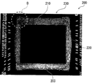
반도체 패키지(200)의 상기 단계를 갖는 제조 방법에서, 열압착 본딩에 의해 제 1 반도체 칩(210)을 배선 기판(230)에 접속할 경우, 도 7의 사진(제 2 반도체 칩(220)이 제거된 상태에서 촬상함)에서 알 수 있는 바와 같이, 제 1 반도체 칩(210)과 배선 기판(230) 사이의 공간의 외주로부터 열경화성 수지막(203)이 흘러나온다. 이 때, 열경화성 수지막(203)은 막(203)의 중심 둘레로 동심원으로(원형으로) 확장되는 성질을 갖는다.
이 제조 단계에서 다음의 문제점을 발견하였다. 제 2 반도체 칩(220)이 제 1 반도체 칩(210)에서 돌출(L: 돌출 길이)하는 설계, 즉 제 2 반도체 칩(220)의 외부 크기가 제 1 반도체 칩(210)의 외부 크기보다 클 경우에, 도 8의 사진(도 7에서의 코너부(B)의 확대 형태) 및 도 9의 개략적인 단면도(도 7의 지면(紙面)에 대해 수직으로 취한 것)에 나타낸 바와 같이, 관련 제조 단계 동안에, 제 2 반도체 칩(220)의 둘레 부분(220a)(특히, 코너부) 아래에 캐비티(C)가 형성되는 경향이 있다. 이러한 캐비티(C)가 형성될 경우, 제 2 반도체 칩(220)의 둘레 부분(220a)의 상면에 형성된 전극을 배선 기판(230) 상에 형성된 전극(233)에 와이어 본딩에 의해 접속하는 단계에서, 제 2 반도체 칩(220)은 휘어질 수 있고, 그 결과 그들의 접속이 불안정해질 수 있다. 또한, 전체 구조를 몰딩하는 단계에서, 제 1 반도체 칩(210)과 제 2 반도체 칩(220) 사이의 계면에 갭(gap)이 형성되어, 몰드 보이드(mold void)의 발생 가능성을 높일 수 있다. 제 2 반도체 칩(220)의 돌출 길이(L)가 클 경우, 이 문제는 더 심각하다.
상기 문제점들의 관점에서, 종래 기술에서는, 제 1 반도체 칩과 배선 기판 사이의 공간으로부터 흘러나오는 열경화성 수지막의 부분을 베이스 부분으로서 이용하여 돌출 길이를 저감함으로써 캐비티의 형성을 방지하려고 한다. 그러나, 공정 조건 및 관련 부재의 치수의 다양함으로 인해, 소정의 형상(이 형상은 흘러나오는 수지의 양에 의존함)을 갖는 베이스를 안정하게 형성하는 것이 매우 곤란하다. 한편, 큰 열경화성 수지막을 이용하여 충분히 넓은 베이스를 확보하려고 하면, 열경화성 수지막이 동심원으로(원형으로) 확장하려는 상술한 성질로 인해, 과도한 양의 수지가 측선(sideline)으로부터 흘러나와서, 배선 기판의 와이어 본딩 전극이 열경화성 수지막의 확장된 부분으로 덮이는 문제를 일으킨다.
본 발명의 예시적인 실시형태는 상기 단점 및 상술하지 않은 다른 단점을 해결한다. 그러나, 본 발명은 상술한 단점을 극복하는데 필수적인 것은 아니며, 따라서 본 발명의 예시적인 실시형태는 상술한 어느 단점을 극복하지 않을 수도 있다.
본 발명의 하나 이상의 실례가 되는 측면에 따르면, 반도체 패키지가 제공된다. 이 반도체 패키지는, 배선 기판; 배선 기판 상에 실장된 제 1 반도체 칩; 제 1 반도체 칩 상에 실장되며, 반도체 패키지의 두께 방향에서 볼 때 제 1 반도체 칩보다 크기가 큰 제 2 반도체 칩; 제 1 반도체 칩을 덮도록, 배선 기판과 제 2 반도체 칩 사이, 및 배선 기판과 1 반도체 칩 사이에 설치된 절연 수지; 및 제 2 반도체 칩에 대면하도록, 배선 기판 상에 배치된 베이스를 포함하며, 절연 수지가 베이스를 덮도록 베이스와 제 2 반도체 칩 사이에 설치된다.
본 발명의 하나 이상의 실례가 되는 측면에 따르면, 반도체 패키지의 제조 방법이 제공된다. 이 방법은 (a) 배선 기판을 준비하는 단계; (b) 배선 기판 상에 베이스를 형성하는 단계; (c) 배선 기판 상에 베이스를 덮도록 열경화성 수지막을 적층하는 단계; 및 (d) 열경화성 수지막을 통해 배선 기판에 제 1 반도체 칩을 가열하면서 가압함으로써, 열경화성 수지막을 통해 배선 기판에 제 1 반도체 칩을 플립칩(flip-chip) 본딩하는 단계를 포함한다.
도 1은 본 발명의 실시형태에 따른 반도체 디바이스의 개략적인 단면도.
도 2의 (a) 내지 도 2의 (c)는 반도체 디바이스의 베이스의 형성 방법을 나타낸 도면.
도 3의 (a) 내지 도 3의 (c)는 본 실시형태에 따른 반도체 패키지의 제조 방법을 설명하는 개략적인 단면도.
도 4의 (a) 내지 도 4의 (c)는 본 실시형태에 따른 반도체 패키지의 제조 방법을 설명하는 개략적인 단면도.
도 5의 (a) 내지 도 5의 (c)는 본 실시형태에 따른 반도체 패키지의 제조 방법을 설명하는 개략적인 단면도.
도 6은 종래 기술의 반도체 패키지의 개략적인 단면도.
도 7은 본 출원인이 시험적으로 제조 및 조사한 반도체 패키지의 구성 및 문제점을 설명하는 사진.
도 8은 본 출원인이 시험적으로 제조 및 조사한 반도체 패키지의 구성 및 문제점을 설명하는 사진.
도 9는 본 출원인이 시험적으로 제조 및 조사한 반도체 패키지의 구성 및 문제점을 설명하는 개략적인 단면도.
본 발명의 다른 측면 및 이점은 다음의 설명, 도면 및 특허청구범위에서 분명해진다.
이하, 본 발명의 예시적인 실시형태를 도면을 참조하여 설명한다. 실시형태의 설명을 위한 모든 도면에서, 동일한 기능을 갖는 부재는 동일한 참조 부호로 나타내고, 그 중복되는 설명을 생략한다.
이하, 본 발명의 실시형태에 따른 반도체 패키지(1)를 설명한다.
도 1은 반도체 패키지의 개략적인 단면도이다. 설명의 편의를 위해, 각각의 도면에 나타낸 부재는 항상 그들의 실제 치수 및 크기에 따라 도시된 것이 아님을 유의한다.
반도체 패키지(1)는, 배선 기판(30) 상에 제 1 반도체 칩(10)을 실장하고, 제 1 반도체 칩(10) 상에 제 2 반도체 칩(20)을 실장한 POP 반도체 패키지이다. 더 구체적으로는, 열압착 본딩에 의해 제 1 반도체 칩(10)을 열경화성 수지막(3)을 통해 배선 기판(30)에 플립칩(flip-chip) 접속하고, 다이 본딩에 의해 제 2 반도체 칩(10)을 제 1 반도체 칩(10)에 본딩한다.
도 3의 (a)에 나타낸 바와 같이, 배선 기판(30)의 상하면에는 제 1 반도체 칩(10)으로의 접속, 또는 외부 접속하기 위한 전극(32, 33)을 형성한다.
제 1 반도체 칩(10)에는, 배선 기판(30)에 대향하는 면(10a)에 전극(32)에 접속되는 접속 범프(11)가 설치된다. 예를 들면, 접속 범프(11)는 금(gold)으로 이루어질 수 있다.
한편, 제 2 반도체 칩(20)의 상면(20e)에는, 둘레 부분(20a)에 대응하는 영역에 전극(도시 생략)이 설치된다. 이 전극은 제 1 반도체 칩(10)의 실장 영역 외측의 배선 기판(30) 상에 설치된 전극(33)에 와이어 본딩된다.
통상적으로, 반도체 패키지(1)는 몰드 수지(6)로 몰딩된다. 그러나, 반도체 패키지(1)는 비몰딩된 형태로 배포될 수 있다.
열압축 본딩에 의해, 제 1 반도체 칩(10)을 열경화성 수지막(3)을 통해 배선 기판(30)에 본딩한다. 제 1 반도체 칩(10) 상에 실장되는 제 2 반도체 칩(20)의 외부 크기는 제 1 반도체 칩(10)의 외부 크기보다 더 크며, 즉 제 2 반도체 칩(20)은 긴 돌출부(overhang)(L: 돌출 길이)를 갖는다. 예를 들면, 제 1 반도체 칩(10)은 측선의 길이가 약 4㎜인 정사각형과 같은 형상으로 되고, 제 2 반도체 칩(20)은 측선 길이가 약 8㎜인 정사각형과 같은 형상으로 된다. 돌출 길이는 약 2㎜이다.
제 2 반도체 칩(20)의 둘레 부분(20a)의 바로 아래에는, 정상부가 제 2 반도체 칩(20)의 저면(20d)과 접촉하지 않는 돌출형 베이스(36)가 설치된다. 도 2의 (a) 내지 도 2의 (c)를 참조하여, 베이스(36)의 예시적인 위치 및 형상을 설명한다. 도 2의 (a)는, 제 2 반도체 칩(20)을 외주선으로만 나타낸 반도체 패키지(1)의 개략적인 평면도이다. 베이스(36)의 작용 효과는 제조 방법의 설명 후에 설명한다.
예를 들면, 제 2 반도체 칩(20)의 코너부(20b)에 대응하는 위치의 배선 기판(30) 상에, 코너 베이스(36a)를 형성한다. 필요하다면, 코너 베이스(36a)와 연속하지 않도록, 제 2 반도체 칩(20)의, 인접하는 코너부(20b) 사이에 각각 위치되는 사이드부(20c)에 대응하는 위치에 사이드 베이스(36b)를 설치한다. 택일적으로, 사이드 베이스(36b)는 코너 베이스(36a)와 연속일 수 있다.
예를 들면, 도 2의 (b)에 나타낸 바와 같이, 각각의 코너 베이스(36a)는 대략 L 형상이 되도록 형성된다. 두 개의 레그(leg)에 의해 형성된 각도(θ)는 0°보다 크고 180°보다 작다. 각각의 코너 베이스(36a)는 각도(θ)가 클 경우 L 형상보다 직선 형상에 더 가깝다. 각각의 코너 베이스(36a)의 코너 반경(R)은 약 0.2㎛보다 크고 약 10㎛보다 작다. 도 2의 (c)에 나타낸 바와 같이, 각각의 코너 베이스(36a)는 큰 챔퍼(chamfer)를 가질 수 있다. 또한 택일적으로, 각각의 코너 베이스(36a)는 둥근 형상(도시 생략)과 같이 형성될 수 있다.
한편, 도 2의 (a)에 나타낸 바와 같이, 각각의 사이드 베이스(36b)는 연관된 사이드부(20c)를 따라 곧게 형성된다.
예를 들면, 코너 베이스(36a) 및 사이드 베이스(36b)는 모두 약 0.3㎜ 내지 0.8㎜ 만큼의 폭을 가지며, 그 폭의 상한은 제 1 반도체 칩(10)의 외주와 배선 기판(30)의 전극(33)(제 2 반도체 칩(20)의 전극에 와이어 본딩됨)의 내주 사이의 거리와 동일하다. 코너 베이스(36a) 및 사이드 베이스(36b) 모두는 대략 10㎛ 내지 수십㎛의 높이를 갖는다.
이 실시형태에 따른 반도체 패키지(1)에서, 베이스(36)는 열경화성 수지막(3)으로 덮이고, 제 1 반도체 칩(10)의 외주 외측인 열경화성 수지막(3) 부분의 상면은 평탄하며 제 1 반도체 칩(10)의 상면과 동일 평면을 이루고, 제 2 반도체 칩(20)의 외주 외측인 열경화성 수지막(3)의 둘레 부분은 필렛(fillet) 형상을 갖는다.
이어서, 반도체 패키지(1)의 제조 방법을 이하 기술한다. 도 3의 (a) ~ 도 3의 (c) 내지 도 5의 (a) ~ 도 5의 (c)는 반도체 패키지(1)의 제조 방법을 설명하는 개략적인 단면도이다.
우선, 도 3의 (a)에 나타낸 바와 같이, 배선 기판(30)을 준비한다. 배선 기판(30)은 수지 기판(31)을 이용하여 공지된 방법에 의해 제조된 인쇄 배선 기판이며, 여기서는 그 제조 공정의 설명을 생략한다. 예를 들면, 배선 기판(30)은 구리로 이루어진 전극(32), 구리 전극(32) 상에 금 도금층이 각각 형성되는 전극(33), 및 솔더 레지스트인 절연층(34)을 포함한다.
도 3의 (b)에 나타낸 바와 같이, 배선 기판(30)의 상면(30a)에 감광성 레지스트(35)를 도포한다. 감광성 레지스트(35)에 마스크 패턴(도시 생략)을 통해 광을 조사한 후, 현상 및 박리를 실시한다. 결과적으로, 도 3의 (c)에 나타낸 바와 같이, 하위 단계에서 제 2 반도체 칩(20)의 둘레 부분(20a)에 의해 점유될 영역 바로 아래에, 소정의 형상을 갖는 베이스(36)를 형성한다.
베이스(36)는, 도 2의 (a) 및 도 2의 (b)를 참조하여 상술한 바와 같이 형성된다. 상기 실시형태에서, 하위 단계에서 제 2 반도체 칩(20)의 코너부(20b)가 배치될 위치에 대응하는 위치의 배선 기판(30)의 상면(30a)에, 코너 베이스(36a)를 형성한다. 그리고, 하위 단계에서 제 2 반도체 칩(20)의, 인접하는 코너부(20b) 사이에 각각 배치된 사이드부(20c)가 배치될 위치에 대응하는 위치의 배선 기판(30)의 상면(30a)에, 사이드 베이스(36b)를 코너 베이스(36a)와 연속하지 않도록 형성한다. 택일적으로, 사이드 베이스(36b)를 코너 베이스(36a)와 연속하도록 형성할 수 있다. 배선 기판(30)의 상면(30a)의 전극(33(33a))의 배열, 제 1 반도체 칩(10)의 형상, 및 다른 요인에 의존하여, 코너 베이스(36a)만을 형성할 수도 있다.
베이스(36)를 형성하는 다른 예의 공정은 라미네이팅법(laminating method)(마스크된 베이스 영역 이외의 영역에 레지스트를 적층함), 플랫플레이트 펀칭법(flat plate punching method)(금속 다이를 이용하여 베이스부 이외의 대부분을 천공함), 및 블라스트법(blast method)(베이스부 이외의 대부분을 분사 처리함)이 있다.
그 후, 도 4의 (a)에 나타낸 바와 같이, 배선 기판(30)의 전극(32) 중 제 1 반도체 칩(10)의 접속 범프(11)가 접속될 전극(32a) 상에, 땜납 피막(37)을 형성한다.
그 후, 도 4의 (b)에 나타낸 바와 같이, 배선 기판(30)의 상면(30a)에서 대상 영역의 중앙에 열경화성 수지막(3)을 적층한다. 더 구체적으로, 베이스(36(36a, 36b))에 의해 획정되는 직사각형 영역(도 2의 (a) 참조)에, 열경화성 수지막(3)을 적층한다. 베이스(36)의 상면에도 열경화성 수지막(3)을 적층한다. 따라서, 이 실시형태에서, 열경화성 수지막(3)은 직사각형 형상을 가진다. 또한, 열경화성 수지막(3)의 측면이 베이스(36)의 바깥 측면과 위치맞춤되도록, 배선 기판(30) 상에 열경화성 수지막(3)을 적층할 수 있다. 그러나, 열경화성 수지막(3)의 형상은 베이스(36)의 배열에 따라 적절하게 변경될 수 있다.
예를 들면, 열경화성 수지막(3)은 에폭시 열경화성 수지로 이루어진다. 그리고 배선 기판(30) 상에 열경화성 수지막(3)을 적층하는 일 예의 방법은 베큠 라미네이션법(vacuum lamination method)이다.
그 후, 도 4의 (c)에 나타낸 바와 같이, 배선 표면(10a)이 배선 기판의 상면(30a)에 대향하는 소정의 실장 위치에서, 배선 기판(30)의 상면(30a)에 열경화성 수지막(3)을 통해 제 1 반도체 칩(10)을 배치한다. 그 후, 제 1 반도체 칩(10)의 배선 표면(10a)의 반대 표면(10b)에, 본딩 툴(가열 헤드)(2)을 가압하고, 본딩 툴(2)에 의해 제 1 반도체 칩(10)을 누르면서 가열을 실시한다.
결과적으로, 제 1 반도체 칩(10)과 배선 기판(30) 사이에 끼워진 열경화성 수지막(3)은 가압 확장되어, 제 1 반도체 칩(10)과 배선 기판(30) 사이의 공간을 채울 뿐만 아니라 제 1 반도체 칩(10)의 외주로부터 베이스(36)의 상면을 넘어서 흐른다. 제 1 반도체 칩(10)의 접속 범프(11)는 배선 기판(30)의 전극(32a) 상의 땜납 피막(37)과 각각 접촉하게 된다. 또한, 배선 기판(30)의 전극(32a) 상의 땜납 피막(37)은 제 1 반도체 칩(10)을 통해 가열되어 용융된다. 서로 접촉되어 있었던 접속 범프(11)와 땜납 피막(37)은 서로 접합된다. 동시에, 제 1 반도체 칩(10)과 배선 기판(30) 사이의 공간을 채운 열경화성 수지막(3)은 가열 경화된다.
이 때, 열경화성 수지막(3)은 베이스(36)를 덮는 형상으로 된다. 제 1 반도체 칩(10)의 외주로부터 흘러나온 열경화성 수지막(3) 부분의 상면은 단차 또는 갭이 전혀 없이 제 1 반도체 칩(10)의 상면(배선 표면(10a)의 반대 표면)과 동일 평면이 되는 평탄면으로 된다. 또한, 제 2 반도체 칩(20)의 외주의 외측에 배치될 열경화성 수지막(3)의 둘레 부분은 필렛 형상을 갖는다.
베이스(36)는 다음의 이점을 준다. 본딩 툴(2)의 가압면과 베이스(36)의 상면과의 사이의 거리는 배선 기판(30)의 상면(30a)과의 사이의 거리보다 짧기 때문에, 증가된 양의 열경화성 수지막(3)이 제 1 반도체 칩(10)의 외주로부터 베이스(36)를 넘어, 흘러나온다.
특히, 증가된 양의 열경화성 수지막(3)이 제 1 반도체 칩(10)의 외주로부터 코너 베이스(36a)를 넘어 흘러나오므로, 자체적으로 동심원으로(원형으로) 확장되는 경향이 있는 열경화성 수지막(3)은 대략 직사각형 형태로 확장될 수 있다. 결과적으로, 제 2 반도체 칩(20)의 외부 크기가 제 1 반도체 칩(10)의 외부 크기보다 커지는 곳에서, 제 2 반도체 칩(20)의 외주부(20a)(특히, 코너부(20b))의 최외측 부분의 바로 아래의 공간으로 열경화성 수지막(3)이 도달할 수 있으므로, 도 9를 참조하여 상술한 바와 같은 캐비티(cavity)의 형성이 방지될 수 있다.
이어서, 도 5의 (a)에 나타낸 바와 같이, 이렇게 형성된 평탄면에 제 2 반도체 칩(20)을 배선 표면(20e)이 위를 향하게 하여 고정 부재(4)를 통해 실장한다. 예를 들면, 제 2 반도체 칩의 실장 후, 경화를 실시함으로써, 고정 부재(4)가 경화되어, 제 1 반도체 칩(10)의 상면(10b)(배선 표면(10a)의 반대 표면) 및 제 1 반도체 칩(10)의 외주로부터 흘러나온 열경화성 수지막(3) 부분의 상면으로 구성되는 평탄면에, 제 2 반도체 칩(20)을 고정한다.
제 1 반도체 칩(10)의 상면(10b)(배선 표면(10a)의 반대 표면) 및 제 1 반도체 칩(10)의 외주로부터 흘러나온 열경화성 수지막(3) 부분의 상면으로 구성되는 평탄면에, 롤 라미네이션법(roll lamination method) 또는 베큠 라미네이션법 등의 라미네이션법에 의해, 수지 재료(예를 들면, 에폭시 수지)로 이루어진 본딩 시트인 고정 부재(4)를 적층한다. 택일적으로, 고정 부재(4)는 에폭시, 폴리이미드, 또는 접착제 등일 수 있다.
그 후, 도 5의 (b)에 나타낸 바와 같이, 제 2 반도체 칩(20)의 배선 표면(20e) 상에 설치된 전극(도시 생략)을 배선 기판(30)의 전극(33(33a))에, 공지된 와이어 본딩법에 의해 금 와이어(5)로 접속한다. 참조 부호 21은, 패스트 본딩(fast bonding) 단계에서 제 2 반도체 칩(20)의 배선 표면(20a)에 설치된 전극에 압착 본딩 볼을 가압할 때, 와이어(5)의 선단에 설치된 압축 본딩 볼의 변형된 형태를 나타낸다.
그 후, 도 5의 (c)에 나타낸 바와 같이, 제 1 반도체 칩(10), 제 2 반도체 칩(20), 와이어(5) 등을 덮도록, 배선 기판(30) 상에 몰드 수지 절연층(밀봉 수지층)(6)을 형성한다. 그 후, 경화 공정에 의해 절연층(6)을 경화한다. 예를 들면, 몰드 수지는 필러(예를 들면, 실리콘 다이옥시드)를 함유하는 수지(이 실시형태에서는, 에폭시 수지)이다. 절연층(6)은 트랜스퍼 몰딩 및 인젝션 몰딩 등의 다양한 방법 중 어느 하나에 의해 형성될 수 있다.
이상, 본 실시형태에 따른 반도체 패키지(1)의 제조 방법의 개별 단계를 설명하였다.
배선 기판(30)의 저면에 설치된 전극(패드)(33(33b))에 땜납 패드 또는 리드 핀(lead pin)을 접속함으로써 외부 접속 단자를 형성할 수 있고, 또는 전극(33(33b))이 외부 접속 단자로서 사용될 수 있다.
상술한 바와 같이, 개시된 반도체 패키지 및 제조 방법에 따르면, 열경화성 수지막을 통해 제 1 반도체 칩에 실장된 제 2 반도체 칩의 외부 크기가 제 1 반도체 칩의 외부 크기보다 큰 POP 반도체 패키지에서, 열경화성 수지막은 제 2 반도체 칩의 둘레 부분(특히, 코너부) 바로 아래의 부분에 도달할 수 있으므로, 거기에서 캐비티가 형성되는 것을 방지할 수 있게 한다.
결과적으로, 제조 공정에서, 제 2 반도체 칩의 상면에 설치된 전극이 배선 기판의 전극에 와이어 본딩될 경우, 제 2 반도체 칩의 휨 등이 방지되며, 최종 접속이 안정해질 수 있다. 또한, 몰딩 단계에서 몰드 보이드의 형성이 억제될 수 있다.
본 발명은 그 특정 예시적인 실시형태를 참조하여 도시 및 기술하였지만, 특허청구범위 내에서 다른 실시도 있다. 첨부된 특허청구범위에 의해 정의된 바와 같은 본 발명의 사상 및 범주에서 벗어나지 않고 그 내에서 형태 및 세부에 다양한 변경이 이루어질 수 있음을 당업자는 이해할 것이다.
1 : 반도체 패키지
2 : 본딩 툴
3 : 열경화성 수지
5 : 와이어
6 : 몰드 수지
10 : 제 1 반도체 칩
11 : 범프
20 : 제 2 반도체 칩
20a : 둘레 부분
20b : 코너부
20c : 사이드부
20d : 저면
30 : 배선 기판
32 : 전극
33 : 전극
34 : 절연층
36 : 베이스
36a : 코너 베이스
36b : 사이드 베이스
37 : 피막
2 : 본딩 툴
3 : 열경화성 수지
5 : 와이어
6 : 몰드 수지
10 : 제 1 반도체 칩
11 : 범프
20 : 제 2 반도체 칩
20a : 둘레 부분
20b : 코너부
20c : 사이드부
20d : 저면
30 : 배선 기판
32 : 전극
33 : 전극
34 : 절연층
36 : 베이스
36a : 코너 베이스
36b : 사이드 베이스
37 : 피막
Claims (13)
- 배선 기판 상에, 열경화성 수지막을 통해 제 1 반도체 칩이 플립 칩 실장 방식에 의해 가열 압착되고, 상기 제 1 반도체 칩 상에, 제 2 반도체 칩이 탑재되어 형성되는 반도체 패키지에 있어서,
상기 배선 기판은 수지 기판에 전극부를 형성하고, 상기 전극부의 일부를 노출하도록, 상기 수지 기판 상에 솔더 레지스트층을 형성하는 것에 의해 이루어져 있으며,
상기 제 2 반도체 칩은 상기 제 1 반도체 칩보다 외형이 크고,
상기 배선 기판의 상기 솔더 레지스트층 상에는, 상기 제 1 반도체 칩의 외주보다 바깥쪽 위치이며, 또한 상기 제 2 반도체 칩의 외연부(外緣部) 바로 아래의 위치에, 당해 제 2 반도체 칩의 하면에 접촉하지 않는 높이의 돌출 형상의 베이스(base)가 설치되고,
상기 열경화성 수지막은, 상기 베이스를 둘러싸는 형상을 가지며, 상기 제 1 반도체 칩의 외주보다 바깥쪽 위치에 있어서의 상면이 당해 제 1 반도체 칩의 상면과 동일한 평탄면으로 형성되고, 또한 상기 제 2 반도체 칩의 외주보다 바깥쪽에 배치되는 외연부가 필렛 형상으로 형성되어 있고,
상기 베이스로서는, 상기 제 2 반도체 칩의 코너부에 대응하는 위치에, 코너 베이스가 설치됨과 함께, 상기 제 2 반도체 칩의 인접하는 코너부 사이의 사이드부(邊部)에 대응하는 위치에, 상기 코너 베이스와 연속적으로 또는 불연속적으로 사이드 베이스가 설치되는 것을 특징으로 하는 반도체 패키지. - 제 1 항에 있어서,
상기 코너 베이스는, L자 형상 또는 원호 형상으로 형성되어 있는 것을 특징으로 하는 반도체 패키지. - 수지 기판에 전극부를 형성하고 상기 전극부의 일부를 노출하도록 상기 수지 기판 상에 솔더 레지스트층을 형성하는 것에 의해 이루어져 있는 배선 기판 상에, 제 1 반도체 칩이 탑재되고, 당해 제 1 반도체 칩 상에, 당해 제 1 반도체 칩보다 외형이 큰 제 2 반도체 칩이 탑재되어 형성되는 반도체 패키지의 제조 방법에 있어서,
상기 배선 기판의 상기 솔더 레지스트층 상에 있어서, 후 공정에서 탑재되는 상기 제 2 반도체 칩의 외연부가 배치될 예정 위치 바로 아래의 위치에, 당해 제 2 반도체 칩의 하면에 접촉하지 않는 높이의 돌출 형상의 베이스를 형성하는 공정과,
상기 배선 기판 상에, 소정 형상의 열경화성 수지막을 통해 플립 칩 실장 방식에 의해 제 1 반도체 칩을 가열 압착하고, 상기 열경화성 수지막은, 상기 베이스를 둘러싸며, 상기 제 1 반도체 칩의 외주보다 바깥쪽 위치에 있어서의 상면이 당해 제 1 반도체 칩의 상면과 동일한 평탄면으로 형성되고, 또한 상기 제 2 반도체 칩의 외주보다 바깥쪽에 배치되는 외연부가 필렛 형상으로 형성되는 공정과,
상기 제 1 반도체 칩 상에, 상기 제 2 반도체 칩을 탑재하는 공정을 구비하고,
상기 베이스를 형성하는 공정은, 상기 제 2 반도체 칩의 코너부가 배치될 예정 위치에 대응하는 위치에, 코너 베이스를 형성하는 공정과, 상기 제 2 반도체 칩의 인접하는 코너부 사이의 사이드부가 배치될 예정 위치에 대응하는 위치에, 상기 코너 베이스와 연속적으로 또는 불연속적으로 사이드 베이스를 형성하는 공정을 갖는 것을 특징으로 하는 반도체 패키지의 제조 방법. - 제 3 항에 있어서,
상기 코너 베이스를, L자 형상 또는 원호 형상으로 형성하는 것을 특징으로 하는 반도체 패키지의 제조 방법. - 제 3 항 또는 제 4 항에 있어서,
상기 제 2 반도체 칩을 탑재하는 공정은,
상기 제 1 반도체 칩 상에, 상기 제 2 반도체 칩을 다이 본딩에 의해 접합하는 공정과,
상기 제 2 반도체 칩의 상면에 설치된 전극부와, 상기 배선 기판 상에 있어서 상기 제 1 반도체 칩의 탑재 위치보다 바깥쪽에 설치된 전극부를 와이어 본딩에 의해 접속하는 공정을 구비하는 것을 특징으로 하는 반도체 패키지의 제조 방법. - 삭제
- 삭제
- 삭제
- 삭제
- 삭제
- 삭제
- 삭제
- 삭제
Applications Claiming Priority (2)
| Application Number | Priority Date | Filing Date | Title |
|---|---|---|---|
| JP2010147196A JP5453678B2 (ja) | 2010-06-29 | 2010-06-29 | 半導体パッケージおよびその製造方法 |
| JPJP-P-2010-147196 | 2010-06-29 |
Publications (2)
| Publication Number | Publication Date |
|---|---|
| KR20120001626A KR20120001626A (ko) | 2012-01-04 |
| KR101730916B1 true KR101730916B1 (ko) | 2017-04-27 |
Family
ID=45351768
Family Applications (1)
| Application Number | Title | Priority Date | Filing Date |
|---|---|---|---|
| KR1020110061455A KR101730916B1 (ko) | 2010-06-29 | 2011-06-24 | 반도체 패키지 및 그 제조 방법 |
Country Status (4)
| Country | Link |
|---|---|
| US (1) | US8803304B2 (ko) |
| JP (1) | JP5453678B2 (ko) |
| KR (1) | KR101730916B1 (ko) |
| TW (1) | TWI527186B (ko) |
Families Citing this family (8)
| Publication number | Priority date | Publication date | Assignee | Title |
|---|---|---|---|---|
| KR102012788B1 (ko) | 2015-09-23 | 2019-08-21 | 주식회사 엘지화학 | 접착 필름, 반도체 장치의 제조 방법 및 반도체 장치 |
| US10373932B2 (en) * | 2017-04-20 | 2019-08-06 | Nanya Technology Corporation | Stacked semiconductor structure |
| US10347507B2 (en) | 2017-09-29 | 2019-07-09 | Lg Innotek Co., Ltd. | Printed circuit board |
| KR102531762B1 (ko) * | 2017-09-29 | 2023-05-12 | 엘지이노텍 주식회사 | 인쇄회로기판 및 이의 제조 방법 |
| KR102491831B1 (ko) * | 2018-01-30 | 2023-01-27 | 쇼와덴코머티리얼즈가부시끼가이샤 | 필름형 접착제 및 그 제조 방법과, 반도체 장치 및 그 제조 방법 |
| KR102565715B1 (ko) | 2019-05-03 | 2023-08-10 | 삼성전자주식회사 | 반도체 패키지 |
| JP7385483B2 (ja) * | 2020-01-27 | 2023-11-22 | キオクシア株式会社 | 半導体装置およびその製造方法 |
| JP2022034947A (ja) | 2020-08-19 | 2022-03-04 | キオクシア株式会社 | 半導体装置およびその製造方法 |
Citations (2)
| Publication number | Priority date | Publication date | Assignee | Title |
|---|---|---|---|---|
| JP2000299431A (ja) * | 1999-04-14 | 2000-10-24 | Sharp Corp | 半導体装置及びその製造方法 |
| JP2005197491A (ja) | 2004-01-08 | 2005-07-21 | Matsushita Electric Ind Co Ltd | 半導体装置 |
Family Cites Families (6)
| Publication number | Priority date | Publication date | Assignee | Title |
|---|---|---|---|---|
| JP2002184936A (ja) | 2000-12-11 | 2002-06-28 | Matsushita Electric Ind Co Ltd | 半導体装置およびその製造方法 |
| JP2002222914A (ja) * | 2001-01-26 | 2002-08-09 | Sony Corp | 半導体装置及びその製造方法 |
| JP2004193174A (ja) * | 2002-12-06 | 2004-07-08 | Matsushita Electric Ind Co Ltd | 半導体装置およびその製造方法 |
| US9129826B2 (en) * | 2005-05-31 | 2015-09-08 | Stats Chippac Ltd. | Epoxy bump for overhang die |
| JP4620553B2 (ja) * | 2005-08-30 | 2011-01-26 | ルネサスエレクトロニクス株式会社 | 半導体装置の製造方法 |
| US8314480B2 (en) * | 2010-02-08 | 2012-11-20 | Fairchild Semiconductor Corporation | Stackable semiconductor package with embedded die in pre-molded carrier frame |
-
2010
- 2010-06-29 JP JP2010147196A patent/JP5453678B2/ja active Active
-
2011
- 2011-06-24 KR KR1020110061455A patent/KR101730916B1/ko active IP Right Grant
- 2011-06-27 US US13/169,335 patent/US8803304B2/en active Active
- 2011-06-29 TW TW100122795A patent/TWI527186B/zh active
Patent Citations (2)
| Publication number | Priority date | Publication date | Assignee | Title |
|---|---|---|---|---|
| JP2000299431A (ja) * | 1999-04-14 | 2000-10-24 | Sharp Corp | 半導体装置及びその製造方法 |
| JP2005197491A (ja) | 2004-01-08 | 2005-07-21 | Matsushita Electric Ind Co Ltd | 半導体装置 |
Also Published As
| Publication number | Publication date |
|---|---|
| JP5453678B2 (ja) | 2014-03-26 |
| US20110316172A1 (en) | 2011-12-29 |
| JP2012015142A (ja) | 2012-01-19 |
| TWI527186B (zh) | 2016-03-21 |
| KR20120001626A (ko) | 2012-01-04 |
| US8803304B2 (en) | 2014-08-12 |
| TW201203500A (en) | 2012-01-16 |
Similar Documents
| Publication | Publication Date | Title |
|---|---|---|
| KR101730916B1 (ko) | 반도체 패키지 및 그 제조 방법 | |
| US8735222B2 (en) | Semiconductor device and method of manufacturing the same | |
| JP5579402B2 (ja) | 半導体装置及びその製造方法並びに電子装置 | |
| US8466545B1 (en) | Stackable semiconductor package | |
| US7633144B1 (en) | Semiconductor package | |
| US20110074037A1 (en) | Semiconductor device | |
| US8895359B2 (en) | Semiconductor device, flip-chip mounting method and flip-chip mounting apparatus | |
| US8274153B2 (en) | Electronic component built-in wiring substrate | |
| JP5980566B2 (ja) | 半導体装置及びその製造方法 | |
| KR20060101385A (ko) | 반도체 장치 및 그 제조 방법 | |
| KR100521279B1 (ko) | 적층 칩 패키지 | |
| US8507805B2 (en) | Wiring board for semiconductor devices, semiconductor device, electronic device, and motherboard | |
| US10811378B2 (en) | Electronic package and manufacturing method thereof | |
| US8648455B2 (en) | Semiconductor device and method of manufacturing the same | |
| JP2009049218A (ja) | 半導体装置及び半導体装置の製造方法 | |
| US8098496B2 (en) | Wiring board for semiconductor device | |
| JP2002093992A (ja) | 半導体装置及びその製造方法 | |
| US20110316151A1 (en) | Semiconductor package and method for manufacturing semiconductor package | |
| KR100874923B1 (ko) | 멀티 스택 패키지, 이의 제조 방법 및 이를 제조하기 위한반도체 패키지 금형 | |
| JP4737995B2 (ja) | 半導体装置 | |
| US8878070B2 (en) | Wiring board and method of manufacturing a semiconductor device | |
| US20030201544A1 (en) | Flip chip package | |
| JP2004079923A (ja) | 半導体装置及びその製造方法 | |
| US20090289347A1 (en) | Circuit board, lead frame, semiconductor device, and method for fabricating the same | |
| US20180301406A1 (en) | Semiconductor package and method for manufacturing the same |
Legal Events
| Date | Code | Title | Description |
|---|---|---|---|
| A201 | Request for examination | ||
| E902 | Notification of reason for refusal | ||
| E701 | Decision to grant or registration of patent right | ||
| GRNT | Written decision to grant |