KR100746897B1 - Rare earth element sintered magnet and method for producing rare earth element sintered magnet - Google Patents
Rare earth element sintered magnet and method for producing rare earth element sintered magnet Download PDFInfo
- Publication number
- KR100746897B1 KR100746897B1 KR1020047010039A KR20047010039A KR100746897B1 KR 100746897 B1 KR100746897 B1 KR 100746897B1 KR 1020047010039 A KR1020047010039 A KR 1020047010039A KR 20047010039 A KR20047010039 A KR 20047010039A KR 100746897 B1 KR100746897 B1 KR 100746897B1
- Authority
- KR
- South Korea
- Prior art keywords
- sintered magnet
- rare earth
- magnet
- hydrogen
- weight
- Prior art date
Links
- 229910052761 rare earth metal Inorganic materials 0.000 title claims abstract description 67
- 238000004519 manufacturing process Methods 0.000 title claims abstract description 15
- UFHFLCQGNIYNRP-UHFFFAOYSA-N Hydrogen Chemical compound [H][H] UFHFLCQGNIYNRP-UHFFFAOYSA-N 0.000 claims abstract description 169
- 238000007747 plating Methods 0.000 claims abstract description 95
- 229910052739 hydrogen Inorganic materials 0.000 claims abstract description 91
- 239000001257 hydrogen Substances 0.000 claims abstract description 91
- 229910052751 metal Inorganic materials 0.000 claims abstract description 67
- 239000002184 metal Substances 0.000 claims abstract description 67
- 150000002910 rare earth metals Chemical class 0.000 claims abstract description 53
- 238000010438 heat treatment Methods 0.000 claims abstract description 34
- 229910044991 metal oxide Inorganic materials 0.000 claims abstract description 25
- 150000004706 metal oxides Chemical class 0.000 claims abstract description 25
- 150000004767 nitrides Chemical class 0.000 claims abstract description 25
- 238000000034 method Methods 0.000 claims description 43
- 239000012298 atmosphere Substances 0.000 claims description 35
- 229910045601 alloy Inorganic materials 0.000 claims description 24
- 239000000956 alloy Substances 0.000 claims description 24
- XKRFYHLGVUSROY-UHFFFAOYSA-N Argon Chemical compound [Ar] XKRFYHLGVUSROY-UHFFFAOYSA-N 0.000 claims description 18
- IJGRMHOSHXDMSA-UHFFFAOYSA-N Atomic nitrogen Chemical compound N#N IJGRMHOSHXDMSA-UHFFFAOYSA-N 0.000 claims description 14
- QVGXLLKOCUKJST-UHFFFAOYSA-N atomic oxygen Chemical compound [O] QVGXLLKOCUKJST-UHFFFAOYSA-N 0.000 claims description 14
- 239000001301 oxygen Substances 0.000 claims description 14
- 229910052760 oxygen Inorganic materials 0.000 claims description 14
- 229910052802 copper Inorganic materials 0.000 claims description 10
- 229910052786 argon Inorganic materials 0.000 claims description 9
- 238000005266 casting Methods 0.000 claims description 8
- 238000010298 pulverizing process Methods 0.000 claims description 8
- 239000012535 impurity Substances 0.000 claims description 7
- 229910052759 nickel Inorganic materials 0.000 claims description 7
- 229910052772 Samarium Inorganic materials 0.000 claims description 6
- 238000002844 melting Methods 0.000 claims description 6
- 230000008018 melting Effects 0.000 claims description 6
- 229910052757 nitrogen Inorganic materials 0.000 claims description 6
- 229910052718 tin Inorganic materials 0.000 claims description 6
- 238000005245 sintering Methods 0.000 claims description 5
- 230000032683 aging Effects 0.000 claims description 4
- 238000005520 cutting process Methods 0.000 claims description 3
- 238000005498 polishing Methods 0.000 claims description 3
- 239000003570 air Substances 0.000 claims description 2
- 239000010410 layer Substances 0.000 description 80
- 230000000052 comparative effect Effects 0.000 description 35
- 239000000203 mixture Substances 0.000 description 28
- 238000000576 coating method Methods 0.000 description 27
- 239000010949 copper Substances 0.000 description 27
- 239000011248 coating agent Substances 0.000 description 26
- 238000004381 surface treatment Methods 0.000 description 26
- 229920005989 resin Polymers 0.000 description 20
- 239000011347 resin Substances 0.000 description 20
- 238000005507 spraying Methods 0.000 description 17
- 230000006866 deterioration Effects 0.000 description 13
- 239000003822 epoxy resin Substances 0.000 description 12
- 229920000647 polyepoxide Polymers 0.000 description 12
- 239000012300 argon atmosphere Substances 0.000 description 11
- 239000000843 powder Substances 0.000 description 9
- 238000005336 cracking Methods 0.000 description 8
- 230000008859 change Effects 0.000 description 7
- 238000005260 corrosion Methods 0.000 description 7
- 230000007797 corrosion Effects 0.000 description 7
- 230000004069 differentiation Effects 0.000 description 6
- 239000007789 gas Substances 0.000 description 6
- 239000000696 magnetic material Substances 0.000 description 6
- 230000001590 oxidative effect Effects 0.000 description 6
- 229910052726 zirconium Inorganic materials 0.000 description 6
- 229910052779 Neodymium Inorganic materials 0.000 description 5
- 239000013078 crystal Substances 0.000 description 5
- 150000002431 hydrogen Chemical class 0.000 description 5
- 229910052742 iron Inorganic materials 0.000 description 5
- 239000002245 particle Substances 0.000 description 5
- 229910052692 Dysprosium Inorganic materials 0.000 description 4
- 239000004593 Epoxy Substances 0.000 description 4
- 229910052777 Praseodymium Inorganic materials 0.000 description 4
- QAOWNCQODCNURD-UHFFFAOYSA-N Sulfuric acid Chemical compound OS(O)(=O)=O QAOWNCQODCNURD-UHFFFAOYSA-N 0.000 description 4
- 229910052782 aluminium Inorganic materials 0.000 description 4
- PNEYBMLMFCGWSK-UHFFFAOYSA-N aluminium oxide Inorganic materials [O-2].[O-2].[O-2].[Al+3].[Al+3] PNEYBMLMFCGWSK-UHFFFAOYSA-N 0.000 description 4
- 238000000227 grinding Methods 0.000 description 4
- 239000007788 liquid Substances 0.000 description 4
- 229910001004 magnetic alloy Inorganic materials 0.000 description 4
- 229910000938 samarium–cobalt magnet Inorganic materials 0.000 description 4
- 238000010583 slow cooling Methods 0.000 description 4
- 229910052689 Holmium Inorganic materials 0.000 description 3
- NINIDFKCEFEMDL-UHFFFAOYSA-N Sulfur Chemical compound [S] NINIDFKCEFEMDL-UHFFFAOYSA-N 0.000 description 3
- 229910052771 Terbium Inorganic materials 0.000 description 3
- 239000002253 acid Substances 0.000 description 3
- 239000000654 additive Substances 0.000 description 3
- KGBXLFKZBHKPEV-UHFFFAOYSA-N boric acid Chemical compound OB(O)O KGBXLFKZBHKPEV-UHFFFAOYSA-N 0.000 description 3
- 239000004327 boric acid Substances 0.000 description 3
- 229910052804 chromium Inorganic materials 0.000 description 3
- XPPKVPWEQAFLFU-UHFFFAOYSA-J diphosphate(4-) Chemical compound [O-]P([O-])(=O)OP([O-])([O-])=O XPPKVPWEQAFLFU-UHFFFAOYSA-J 0.000 description 3
- 235000011180 diphosphates Nutrition 0.000 description 3
- 238000007598 dipping method Methods 0.000 description 3
- 238000004070 electrodeposition Methods 0.000 description 3
- 238000009713 electroplating Methods 0.000 description 3
- 229910052733 gallium Inorganic materials 0.000 description 3
- 239000011261 inert gas Substances 0.000 description 3
- 229910052748 manganese Inorganic materials 0.000 description 3
- 239000000463 material Substances 0.000 description 3
- 229910052750 molybdenum Inorganic materials 0.000 description 3
- VLKZOEOYAKHREP-UHFFFAOYSA-N n-Hexane Chemical compound CCCCCC VLKZOEOYAKHREP-UHFFFAOYSA-N 0.000 description 3
- 229910052758 niobium Inorganic materials 0.000 description 3
- 230000008569 process Effects 0.000 description 3
- 238000010791 quenching Methods 0.000 description 3
- 229910052710 silicon Inorganic materials 0.000 description 3
- 229910052717 sulfur Inorganic materials 0.000 description 3
- 239000011593 sulfur Substances 0.000 description 3
- 239000002344 surface layer Substances 0.000 description 3
- 229910052719 titanium Inorganic materials 0.000 description 3
- 229910052720 vanadium Inorganic materials 0.000 description 3
- 229910052725 zinc Inorganic materials 0.000 description 3
- VEXZGXHMUGYJMC-UHFFFAOYSA-M Chloride anion Chemical compound [Cl-] VEXZGXHMUGYJMC-UHFFFAOYSA-M 0.000 description 2
- ISWSIDIOOBJBQZ-UHFFFAOYSA-N Phenol Chemical compound OC1=CC=CC=C1 ISWSIDIOOBJBQZ-UHFFFAOYSA-N 0.000 description 2
- NIXOWILDQLNWCW-UHFFFAOYSA-N acrylic acid group Chemical group C(C=C)(=O)O NIXOWILDQLNWCW-UHFFFAOYSA-N 0.000 description 2
- 230000000996 additive effect Effects 0.000 description 2
- 230000015572 biosynthetic process Effects 0.000 description 2
- 229910052796 boron Inorganic materials 0.000 description 2
- 230000006835 compression Effects 0.000 description 2
- 238000007906 compression Methods 0.000 description 2
- 238000000748 compression moulding Methods 0.000 description 2
- PEVJCYPAFCUXEZ-UHFFFAOYSA-J dicopper;phosphonato phosphate Chemical compound [Cu+2].[Cu+2].[O-]P([O-])(=O)OP([O-])([O-])=O PEVJCYPAFCUXEZ-UHFFFAOYSA-J 0.000 description 2
- 229910001873 dinitrogen Inorganic materials 0.000 description 2
- IRXRGVFLQOSHOH-UHFFFAOYSA-L dipotassium;oxalate Chemical compound [K+].[K+].[O-]C(=O)C([O-])=O IRXRGVFLQOSHOH-UHFFFAOYSA-L 0.000 description 2
- 230000000694 effects Effects 0.000 description 2
- 238000005121 nitriding Methods 0.000 description 2
- 230000003647 oxidation Effects 0.000 description 2
- 238000007254 oxidation reaction Methods 0.000 description 2
- 229920000728 polyester Polymers 0.000 description 2
- 229920001296 polysiloxane Polymers 0.000 description 2
- 239000004814 polyurethane Substances 0.000 description 2
- 229920002635 polyurethane Polymers 0.000 description 2
- 230000000171 quenching effect Effects 0.000 description 2
- 239000002994 raw material Substances 0.000 description 2
- RYCLIXPGLDDLTM-UHFFFAOYSA-J tetrapotassium;phosphonato phosphate Chemical compound [K+].[K+].[K+].[K+].[O-]P([O-])(=O)OP([O-])([O-])=O RYCLIXPGLDDLTM-UHFFFAOYSA-J 0.000 description 2
- 238000007740 vapor deposition Methods 0.000 description 2
- 238000005406 washing Methods 0.000 description 2
- 229910052684 Cerium Inorganic materials 0.000 description 1
- 229910002482 Cu–Ni Inorganic materials 0.000 description 1
- LFQSCWFLJHTTHZ-UHFFFAOYSA-N Ethanol Chemical compound CCO LFQSCWFLJHTTHZ-UHFFFAOYSA-N 0.000 description 1
- 229910052688 Gadolinium Inorganic materials 0.000 description 1
- 229910003298 Ni-Ni Inorganic materials 0.000 description 1
- 229910018484 Ni—Cu—Ni Inorganic materials 0.000 description 1
- QAOWNCQODCNURD-UHFFFAOYSA-L Sulfate Chemical compound [O-]S([O-])(=O)=O QAOWNCQODCNURD-UHFFFAOYSA-L 0.000 description 1
- 230000002411 adverse Effects 0.000 description 1
- 239000003513 alkali Substances 0.000 description 1
- 230000008901 benefit Effects 0.000 description 1
- 238000001816 cooling Methods 0.000 description 1
- 238000005238 degreasing Methods 0.000 description 1
- 230000002542 deteriorative effect Effects 0.000 description 1
- 230000004907 flux Effects 0.000 description 1
- 125000004435 hydrogen atom Chemical group [H]* 0.000 description 1
- 229910000765 intermetallic Inorganic materials 0.000 description 1
- 238000007733 ion plating Methods 0.000 description 1
- 150000002500 ions Chemical class 0.000 description 1
- 238000000465 moulding Methods 0.000 description 1
- 238000009740 moulding (composite fabrication) Methods 0.000 description 1
- 239000012299 nitrogen atmosphere Substances 0.000 description 1
- -1 oxide Chemical class 0.000 description 1
- 239000003973 paint Substances 0.000 description 1
- 238000006748 scratching Methods 0.000 description 1
- 230000002393 scratching effect Effects 0.000 description 1
- 239000002904 solvent Substances 0.000 description 1
- 238000004544 sputter deposition Methods 0.000 description 1
- 238000003860 storage Methods 0.000 description 1
- 239000000126 substance Substances 0.000 description 1
- 230000008719 thickening Effects 0.000 description 1
- 229910052723 transition metal Inorganic materials 0.000 description 1
- 150000003624 transition metals Chemical class 0.000 description 1
- 238000001771 vacuum deposition Methods 0.000 description 1
- XLYOFNOQVPJJNP-UHFFFAOYSA-N water Substances O XLYOFNOQVPJJNP-UHFFFAOYSA-N 0.000 description 1
Images


Classifications
-
- H—ELECTRICITY
- H01—ELECTRIC ELEMENTS
- H01F—MAGNETS; INDUCTANCES; TRANSFORMERS; SELECTION OF MATERIALS FOR THEIR MAGNETIC PROPERTIES
- H01F1/00—Magnets or magnetic bodies characterised by the magnetic materials therefor; Selection of materials for their magnetic properties
- H01F1/01—Magnets or magnetic bodies characterised by the magnetic materials therefor; Selection of materials for their magnetic properties of inorganic materials
- H01F1/03—Magnets or magnetic bodies characterised by the magnetic materials therefor; Selection of materials for their magnetic properties of inorganic materials characterised by their coercivity
- H01F1/032—Magnets or magnetic bodies characterised by the magnetic materials therefor; Selection of materials for their magnetic properties of inorganic materials characterised by their coercivity of hard-magnetic materials
- H01F1/04—Magnets or magnetic bodies characterised by the magnetic materials therefor; Selection of materials for their magnetic properties of inorganic materials characterised by their coercivity of hard-magnetic materials metals or alloys
- H01F1/047—Alloys characterised by their composition
- H01F1/053—Alloys characterised by their composition containing rare earth metals
- H01F1/055—Alloys characterised by their composition containing rare earth metals and magnetic transition metals, e.g. SmCo5
- H01F1/057—Alloys characterised by their composition containing rare earth metals and magnetic transition metals, e.g. SmCo5 and IIIa elements, e.g. Nd2Fe14B
- H01F1/0571—Alloys characterised by their composition containing rare earth metals and magnetic transition metals, e.g. SmCo5 and IIIa elements, e.g. Nd2Fe14B in the form of particles, e.g. rapid quenched powders or ribbon flakes
- H01F1/0575—Alloys characterised by their composition containing rare earth metals and magnetic transition metals, e.g. SmCo5 and IIIa elements, e.g. Nd2Fe14B in the form of particles, e.g. rapid quenched powders or ribbon flakes pressed, sintered or bonded together
- H01F1/0577—Alloys characterised by their composition containing rare earth metals and magnetic transition metals, e.g. SmCo5 and IIIa elements, e.g. Nd2Fe14B in the form of particles, e.g. rapid quenched powders or ribbon flakes pressed, sintered or bonded together sintered
-
- H—ELECTRICITY
- H01—ELECTRIC ELEMENTS
- H01F—MAGNETS; INDUCTANCES; TRANSFORMERS; SELECTION OF MATERIALS FOR THEIR MAGNETIC PROPERTIES
- H01F1/00—Magnets or magnetic bodies characterised by the magnetic materials therefor; Selection of materials for their magnetic properties
- H01F1/01—Magnets or magnetic bodies characterised by the magnetic materials therefor; Selection of materials for their magnetic properties of inorganic materials
- H01F1/03—Magnets or magnetic bodies characterised by the magnetic materials therefor; Selection of materials for their magnetic properties of inorganic materials characterised by their coercivity
- H01F1/032—Magnets or magnetic bodies characterised by the magnetic materials therefor; Selection of materials for their magnetic properties of inorganic materials characterised by their coercivity of hard-magnetic materials
- H01F1/04—Magnets or magnetic bodies characterised by the magnetic materials therefor; Selection of materials for their magnetic properties of inorganic materials characterised by their coercivity of hard-magnetic materials metals or alloys
- H01F1/047—Alloys characterised by their composition
- H01F1/053—Alloys characterised by their composition containing rare earth metals
- H01F1/055—Alloys characterised by their composition containing rare earth metals and magnetic transition metals, e.g. SmCo5
- H01F1/0555—Alloys characterised by their composition containing rare earth metals and magnetic transition metals, e.g. SmCo5 pressed, sintered or bonded together
- H01F1/0557—Alloys characterised by their composition containing rare earth metals and magnetic transition metals, e.g. SmCo5 pressed, sintered or bonded together sintered
-
- H—ELECTRICITY
- H01—ELECTRIC ELEMENTS
- H01F—MAGNETS; INDUCTANCES; TRANSFORMERS; SELECTION OF MATERIALS FOR THEIR MAGNETIC PROPERTIES
- H01F41/00—Apparatus or processes specially adapted for manufacturing or assembling magnets, inductances or transformers; Apparatus or processes specially adapted for manufacturing materials characterised by their magnetic properties
- H01F41/02—Apparatus or processes specially adapted for manufacturing or assembling magnets, inductances or transformers; Apparatus or processes specially adapted for manufacturing materials characterised by their magnetic properties for manufacturing cores, coils, or magnets
- H01F41/0253—Apparatus or processes specially adapted for manufacturing or assembling magnets, inductances or transformers; Apparatus or processes specially adapted for manufacturing materials characterised by their magnetic properties for manufacturing cores, coils, or magnets for manufacturing permanent magnets
- H01F41/026—Apparatus or processes specially adapted for manufacturing or assembling magnets, inductances or transformers; Apparatus or processes specially adapted for manufacturing materials characterised by their magnetic properties for manufacturing cores, coils, or magnets for manufacturing permanent magnets protecting methods against environmental influences, e.g. oxygen, by surface treatment
Abstract
Sm2Co17계 또는 R2Fe14B계 자석에 금속 도금을 행한 후, 열처리를 행하거나, 또는 금속 도금층상에(또는 자석에 직접) 금속 산화물 또는 질화물층을 형성함으로써, 수소취성을 방지한다.
Hydrogen embrittlement is prevented by subjecting the Sm 2 Co 17 or R 2 Fe 14 B magnet to metal plating followed by heat treatment or by forming a metal oxide or nitride layer on the metal plating layer (or directly to the magnet). .
희토류 소결 자석, 제조 방법, 금속 도금, 열처리, 수소취성.Rare earth sintered magnet, manufacturing method, metal plating, heat treatment, hydrogen embrittlement.
Description
본 발명은, 수소 분위기에 장시간 노출되는 모터 등에 사용되는 희토류 소결 자석 및 그 제조 방법에 관한 것이다. The present invention relates to a rare earth sintered magnet for use in a motor or the like exposed to a hydrogen atmosphere for a long time, and a manufacturing method thereof.
희토류 원소와 전이 금속의 금속간 화합물에서는, 수소가 결정격자사이에 침입하는, 즉, 합금중에 수소를 흡장, 방출하는 특성을 갖고 있고, 그 특성은 다양한 분야에서 이용되고 있다. 그 예로서는, LaNi5로 대표되는 수소 흡장 합금에 의한 수소 전지를 들 수 있고, 또, 희토류 소결 자석에 있어서도, R2Fe14B계 합금의 분쇄 방법으로서, 또한 R2Fe14B계 본드 자석의 제조 방법(HDDR 일본 특개평 3-129702호 공보)으로서 이용되고 있다. In an intermetallic compound of a rare earth element and a transition metal, hydrogen penetrates between crystal lattice, that is, it occludes and releases hydrogen in an alloy, and the characteristic is used in various fields. Examples thereof include a hydrogen battery based on a hydrogen occlusion alloy represented by LaNi 5 , and also in a rare earth sintered magnet, as a grinding method of an R 2 Fe 14 B-based alloy, the R 2 Fe 14 B-based bond magnet It is used as a manufacturing method (HDDR Unexamined-Japanese-Patent No. 3-129702).
그렇지만, 합금중 또는 자석중에 수소를 흡장, 방출시킨 경우, 수소취성을 일으켜 버린다. 그 때문에, 수소 분위기중에서, 희토류 소결 자석을 사용한 모터 등을 사용한 경우, 희토류 소결 자석이 수소 취화를 일으키고, 소재에 깨어짐, 크랙 또는 분화가 일어난다고 하는 문제가 생기고 있다. However, when hydrogen is occluded and released in the alloy or in the magnet, hydrogen embrittlement occurs. Therefore, when a motor using a rare earth sintered magnet or the like is used in a hydrogen atmosphere, the rare earth sintered magnet causes hydrogen embrittlement, causing a problem of cracking, cracking or differentiation of the material.
현재, 희토류 소결 자석에는, R2Fe14B계, SmCo5계, Sm2Co17 계 등의 종류가 있 다. 일반적으로, 수소에 대해서는, 2-17형 결정 구조보다도 1-5형 결정 구조, 1-5형 결정 구조보다도 2-7형 결정 구조의 쪽이 플래토 압력이 낮아, 즉, 희토류 원소 리치(이하, R리치라고 칭한다)한 합금쪽이 수소 흡장되기 쉬운 경향에 있어, 수소 취화하기 쉽다. Currently, rare earth sintered magnets include R 2 Fe 14 B system, SmCo 5 system, and Sm 2 Co 17 system. In general, about hydrogen, the 1-5 type crystal structure than the 2-17 type crystal structure and the 2-7 type crystal structure than the 1-5 type crystal structure have lower platen pressure, that is, rare earth element rich (hereinafter, Alloy, which is referred to as R-rich, tends to be easily occluded in hydrogen and easily embrittles hydrogen.
R2Fe14B계 자석은, 자석중에 R리치상을 갖기 때문에, 0.1MPa 이하의 압력의 수소 분위기하에서, 용이하게 수소취성을 일으켜, 자석 소재에 깨어짐, 크랙 또는 분화가 생긴다. 통상, R2Fe14B계 자석은, 내식성 향상을 위해 도금, 수지 코팅 등의 표면처리가 이루어져 있지만, 수소 취화를 방지하는 수단은 되지 못한다. 이 문제를 해결하는 방법으로서, R2Fe14B계 자석의 표면처리막에 수소 흡장 합금을 함유시키는 방법을 제안했다(일본 특개 2000-285415호 공보). 이 방법에 의해 제작된 R2Fe14B계 자석은, 0.1MPa 이하의 압력의 수소 분위기하에서는, 수소취성을 일으키지 않는 것이지만, 그것을 초과하는 압력의 수소 분위기하에서는, 수소취성을 일으켜, 자석 소재에 깨어짐, 크랙 또는 분화가 생긴다고 생각된다. Since the R 2 Fe 14 B-based magnet has a R-rich phase in the magnet, hydrogen embrittlement easily occurs in a hydrogen atmosphere at a pressure of 0.1 MPa or less, and cracks, cracks, or differentiation of the magnetic material occur. Usually, although the R 2 Fe 14 B-based magnet is subjected to surface treatment such as plating and resin coating for improving corrosion resistance, it is not a means for preventing hydrogen embrittlement. As a method of solving this problem, a method of containing a hydrogen storage alloy in the surface treatment film of a R 2 Fe 14 B-based magnet has been proposed (Japanese Patent Laid-Open No. 2000-285415). The R 2 Fe 14 B-based magnet produced by this method does not cause hydrogen embrittlement in a hydrogen atmosphere at a pressure of 0.1 MPa or less, but in a hydrogen atmosphere at a pressure exceeding that, it causes hydrogen embrittlement and breaks into a magnetic material. It is thought that crack, or eruption occurs.
SmCo5계 자석도, R2Fe14B계 자석과 마찬가지로, R리치상을 갖는 동시에, 주 상인 SmCo5상의 플래토 압력이 약 0.3MPa이다. 이 때문에, 0.3MPa를 초과하는 압력의 수소 분위기중에서는, 수소취성을 일으켜, 자석 소재에 깨어짐, 크랙 또는 분화가 생긴다. Similarly to the R 2 Fe 14 B-based magnet, the SmCo 5 magnet has a R-rich phase and a plateau pressure of about 0.3 MPa in the SmCo 5 phase as the main phase. For this reason, in a hydrogen atmosphere at a pressure exceeding 0.3 MPa, hydrogen embrittlement occurs and cracks, cracks or differentiation occur in the magnetic material.
Sm2Co17계 자석은, 주요 상이 2-17상이고, R2Fe14B계, SmCo 5계에 비해 R리치는 아닌 것으로, R리치상을 함유하지 않기 때문에, 수소취성을 일으키기 어렵다. 그렇지만, 1MPa를 초과하는 압력의 수소 분위기중에서는, 다른 희토류 소결 자석과 마찬가지로, 수소취성을 일으켜, 자석 소재에 깨어짐, 크랙 또는 분화가 생기는 것이다. Sm 2 Co 17- based magnets are 2-17 phases and are not R-rich as compared to R 2 Fe 14 B-based and SmCo 5 -based, and do not contain an R-rich phase, and therefore are hard to cause hydrogen embrittlement. However, in a hydrogen atmosphere at a pressure exceeding 1 MPa, like other rare earth sintered magnets, hydrogen embrittlement occurs, causing cracking, cracking or differentiation of the magnetic material.
본 발명은, 종래의 희토류 소결 자석과 같이 수소 분위기하에서 수소취성을 일으켜 자석 소재에 깨어짐, 크랙 또는 분화가 생긴다고 하는 문제를 해결한 희토류 소결 자석 및 그 제조 방법을 제공하는 것을 목적으로 한다. An object of the present invention is to provide a rare earth sintered magnet and a method for producing the same, which solves the problem that cracking, cracking or differentiation occurs in a magnetic material due to hydrogen embrittlement in a hydrogen atmosphere as in the conventional rare earth sintered magnet.
즉, 본 발명자들은, 먼저 내수소취성을 향상시키기 위해, Sm2Co17계 자석을 소결 자석으로 하고, 절단 및/또는 연마하여 표면을 가공 후, 산소분압 10-6~ 152torr의 분위기에서 열처리하는 것, 또는 Sm2Co17계 자석의 표면에 Co 및/또는 Co, Fe 중에 Sm203이 미세하게 분산되어 있는 층을 존재시키는 것을 제안했다(일본 특개 2002-118009호 공보). 이와 같이 하여 자석 표면에 Co 및/또는 Co, Fe 중에 Sm203이 미세하게 분산되어 있는 층을 존재시키면, 3MPa를 초과하는 고압수소 분위기하에서도 수소취성은 일어나지 않는다. 그러나, Sm2Co17계 자석 및 Co 및/또는 Co, Fe 중에 Sm203이 미세하게 분산되어 있는 층은, 딱딱하고, 깨지기 쉽기 때문에, 제품 조립 등 취급시, 치핑 등을 일으키는 경우가 있다. 치핑 등을 일으킨 희토류 소결 자석은, 자기 특성에는 거의 영향은 없지만, 내수소취성은 크게 저하되어, 표 면층이 없는 경우와 마찬가지로 되어 버린다. That is, the present inventors, first, in order to improve the hydrogen embrittlement resistance, the Sm 2 Co 17- based magnet is used as a sintered magnet, cut and / or polished to process the surface, and then heat treated in an atmosphere of oxygen partial pressure of 10 -6 ~ 152torr It is proposed to have a layer in which Sm 2 O 3 is finely dispersed in Co and / or Co, Fe on the surface of the Sm 2 Co 17 system magnet (Japanese Patent Laid-Open No. 2002-118009). In this way, when a layer in which Sm 2 O 3 is finely dispersed in Co and / or Co, Fe is present on the magnet surface, hydrogen embrittlement does not occur even under a high-pressure hydrogen atmosphere exceeding 3 MPa. However, the Sm 2 Co 17- based magnets and the layers in which Sm 2 O 3 is finely dispersed in Co and / or Co and Fe are hard and brittle, so that chipping or the like may occur during product assembly or the like. . Rare earth sintered magnets that cause chipping have little effect on the magnetic properties, but the hydrogen embrittlement resistance is greatly lowered and becomes similar to the case where there is no surface layer.
따라서, 1MPa를 초과하는 압력의 수소 분위기중에서는, 수소취성을 일으켜, 자석 소재에 깨어짐, 크랙 또는 분화가 일어나기 때문에, 그와 같은 분위기중에서는 사용할 수 없다. 즉, Sm2Co17계 자석의 기계적 강도를 향상시키거나, 또는 치핑을 방지할 수 있으면, 내수소성을 유지한다고 생각된다. Therefore, in a hydrogen atmosphere at a pressure exceeding 1 MPa, hydrogen embrittlement occurs and cracking, cracking or differentiation occurs in the magnetic material, and therefore, it cannot be used in such atmosphere. That is, if the mechanical strength of an Sm 2 Co 17- based magnet can be improved or chipping can be prevented, it is considered to maintain hydrogen resistance.
상기 문제는, Sm2Co17계 자석의 기계적 강도의 취성에 기인하는 것이다. 한편, 소재로서, Sm2Co17계 자석보다 R2Fe14B계 자석의 쪽이 기계적 강도는 강하고, 또한 통상, 내산화성 피막을 갖고 있기 때문에, 치핑 등의 가능성은 낮아, R2Fe14B계 자석에 내수소성 피막을 피복할 수 있으면 유효하다고 생각된다. The problem is due to the brittleness of the mechanical strength of the Sm 2 Co 17 magnet. On the other hand, as a material, Sm 2 Co because it has a 17-based magnet oxidation film R 2 Fe 14 B-based magnets, mechanical strength is strong, and usually, the side of more, less likely, such as chipping, R 2 Fe 14 B It is considered effective if the hydrogen-resistant coating can be coated on the system magnet.
이 경우, R2Fe14B계 자석은, Sm2Co17계 자석과 비교하여, 내식성이 뒤떨어지고 있고 및 온도 특성이 뒤떨어지는 등의 결점이 있지만, 주요 원소가, 고가인 Sm, Co가 아니라, 저렴한 Nd, Fe이기 때문에, 원재료비가 저렴할 뿐만 아니라, 현재 양산되고 있는 최고 자기 특성에 있어서도, Sm2Co17계 자석의 32MGOe에 대하여, R2 Fe14B계 자석의 50MGOe의 최대 에너지곱과 같이 우수하다고 하는 이점이 있다. 즉, R2Fe14B계 자석은, 내식성 향상을 위한 표면처리가 행해져 있으면, 상온에서, 극히 우수한 영구자석 재료이고, 그 때문에, 우수한 온도 특성을 필요로 하지 않는 경우 또는 150℃ 이상의 온도가 걸리지 않는 경우라면, 통상, 자기 회로의 소형화, 고효율화를 위해서는, Sm2Co17계 자석이 아니라, R2Fe14B계 자석이 사용되는 경우가 많다. 즉, 자기 특성에 있어서도, Sm2Co17계 자석보다도 R2Fe14B계 자석이 내수소성을 가지면, 상당히 유효하다는 것은 분명하다. In this case, the R 2 Fe 14 B-based magnets have disadvantages such as inferior corrosion resistance and inferior temperature characteristics as compared to Sm 2 Co 17- based magnets, but the main elements are not expensive Sm or Co. Because of the low cost of Nd and Fe, the raw material cost is not only low, but also in the highest magnetic properties currently in mass production, it is equal to the maximum energy product of 50 MGOe of the R 2 Fe 14 B type magnet against 32 MGOe of the Sm 2 Co 17 magnet. There is an advantage of being excellent. That is, the R 2 Fe 14 B-based magnet is a permanent magnet material which is extremely excellent at room temperature, provided that the surface treatment for improving the corrosion resistance is performed, and therefore, does not require excellent temperature characteristics or a temperature of 150 ° C. or higher. If not, the R 2 Fe 14 B magnets are often used instead of the Sm 2 Co 17 magnets for miniaturization and high efficiency of the magnetic circuit. In other words, it is evident that the R 2 Fe 14 B-based magnet is considerably more effective than the Sm 2 Co 17- based magnet in terms of its magnetic properties.
본 발명자들은, 이상의 상황하에서, 상기 목적을 달성하기 위해 예의 검토를 행한 결과, 소결, 시효 후의 소결 자석을 표면 가공 후, 금속 도금을 행하고, 더욱 최적의 열처리를 함으로써, 자석체 표면에 내수소성이 우수한 층을 형성한다고 하는, 고압의 수소 분위기중에서도 수소취성을 일으키지 않는 희토류 소결 자석의 제조 방법을 알아냈다. 이것으로부터, 수소 분위기에 장시간 노출된 모터 등에 매우 적합하게 사용되는 Sm2Co17계 또는 R2Fe14B계 소결 자석을 얻을 수 있는 것을 알아냈다. MEANS TO SOLVE THE PROBLEM In the above situation, as a result of earnestly examining in order to achieve the said objective, the present inventors carried out metal plating after surface-processing the sintered magnet after sintering and aging, and performs a more optimal heat treatment, and therefore hydrogen resistance is made to the surface of a magnet body. The manufacturing method of the rare earth sintered magnet which does not produce hydrogen embrittlement in the high pressure hydrogen atmosphere which forms an excellent layer was discovered. From this, it was found that to obtain a very long period of time suitable for use Sm 2 Co 17 type or an R 2 Fe 14 B-based sintered magnet or the like exposed motor in a hydrogen atmosphere.
또, Sm2Co17계 또는 R2Fe14B계 소결 자석의 표면에, 직접 또는 금속 도금층을 개재하여 금속 산화물층 및/또는 금속 질화물층을 형성함으로써, 고압의 수소 분위기중에서도 수소취성을 일으키지 않고, 이 때문에, 수소 분위기에 장시간 노출되는 모터 등에 매우 적합하게 사용되는 Sm2Co17계 또는 R2Fe14B계 소결 자석을 얻을 수 있다는 것을 알아내고, 본 발명을 완성하기에 이르렀다. In addition, by forming a metal oxide layer and / or a metal nitride layer on the surface of the Sm 2 Co 17- based or R 2 Fe 14 B-based sintered magnet directly or through a metal plating layer, hydrogen embrittlement is not caused even in a high-pressure hydrogen atmosphere. , to find out that there is a reason, to obtain a long exposure Sm 2 Co 17 type or R 2 Fe 14 B-based sintered magnet to be used is very suitable for a motor in a hydrogen atmosphere, thus completing the present invention.
따라서, 본 발명은, 하기 (1)~(4)의 희토류 소결 자석 및 그 제조 방법을 제공하는 것이다. Therefore, this invention provides the rare earth sintered magnet of the following (1)-(4), and its manufacturing method.
(1) R(단, R은 Sm 또는 Sm을 50중량% 이상 포함하는 2종 이상의 희토류 원소) 20~30중량%, Fe 10~45중량%, Cu 1~10중량%, Zr 0.5~5중량%, 잔부 Co 및 불가피한 불순물로 이루어진 합금을 용해, 주조하고, 분쇄, 미분쇄, 자장중 성형, 소결, 시효를 순차적으로 행하여 소결 자석으로 하고, 더욱 그 소결 자석을 절단 및/또는 연마하여 표면을 가공 후, 금속 도금을 행하고, 그 후, 80~850℃에서 10분~50시간 열처리하는 것을 특징으로 하는 희토류 소결 자석의 제조 방법. (1) 20-30% by weight of R (where R is Sm or two or more rare earth elements containing 50% by weight or more of Sm), 10-45% by weight of Fe, 1-10% by weight of Cu, and 0.5-5% by weight of Zr. The alloy consisting of%, balance Co and unavoidable impurities is dissolved and cast, followed by pulverization, pulverization, molding in a magnetic field, sintering and aging sequentially to form a sintered magnet, and furthermore, the surface of the sintered magnet is cut and / or polished. The metal plating is performed after processing and heat-processed at 80-850 degreeC for 10 minutes-50 hours after that, The manufacturing method of the rare earth sintered magnet characterized by the above-mentioned.
(2) R(단, R은 Sm 또는 Sm을 50중량% 이상 포함하는 2종 이상의 희토류 원소) 20~30중량%, Fe 10~45중량%, Cu 1~10중량%, Zr O.5~5중량%, 잔부 Co 및 불가피한 불순물로 이루어진 희토류 소결 자석에 있어서, 그 희토류 소결 자석의 표면에, 직접 또는 금속 도금층을 개재하여 금속 산화물층 및/또는 금속 질화물층을 갖는 것을 특징으로 하는 희토류 소결 자석. (2) 20 to 30% by weight of R (wherein R is two or more rare earth elements containing 50% by weight or more of Sm or Sm), 10 to 45% by weight of Fe, 1 to 10% by weight of Cu, and Zr 0.5 to 5% A rare earth sintered magnet composed of 5% by weight, balance Co and unavoidable impurities, wherein the rare earth sintered magnet has a metal oxide layer and / or a metal nitride layer on the surface of the rare earth sintered magnet directly or via a metal plating layer. .
(3) R(R은, Nd, Pr, Dy, Tb 및 Ho로부터 선택되는 1종 또는 2종 이상의 희토류 원소)을 20~35중량%, Co를 15중량% 이하, B를 0.2~8중량%, 첨가물로서 Ni, Nb, Al, Ti, Zr, Cr, V, Mn, Mo, Si, Sn, Ga, Cu 및 Zn으로부터 선택되는 적어도 1종의 원소를 8중량% 이하, 잔부 Fe 및 불가피한 불순물로 이루어진 합금을 용해, 주조하고, 분쇄, 미분쇄, 자장중 성형, 소결, 열처리를 순차적으로 행하여 소결 자석으로 하고, 더욱 그 소결 자석을 절단 및/또는 연마하여 표면을 가공 후, 금속 도금을 행하고, 그 후, 80~700℃에서 10분~50시간 열처리하는 것을 특징으로 하는 희토류 소결 자석의 제조 방법. (3) 20 to 35 wt% of R (R is one or two or more rare earth elements selected from Nd, Pr, Dy, Tb, and Ho), 15 wt% or less of Co, and 0.2-8 wt% of B; At least one element selected from Ni, Nb, Al, Ti, Zr, Cr, V, Mn, Mo, Si, Sn, Ga, Cu, and Zn as an additive to 8 wt% or less, balance Fe and unavoidable impurities The alloy thus formed is melted, cast, pulverized, finely pulverized, molded in a magnetic field, sintered, and heat treated in order to form a sintered magnet, and further, the sintered magnet is cut and / or polished to process the surface, followed by metal plating. After that, heat treatment is carried out at 80 to 700 ° C for 10 minutes to 50 hours.
(4) R(R은, Nd, Pr, Dy, Tb 및 Ho로부터 선택되는 1종 또는 2종 이상의 희토류 원소)을 20~35중량%, Co를 15중량% 이하, B를 0.2~8중량%, 첨가물로서 Ni, Nb, Al, Ti, Zr, Cr, V, Mn, Mo, Si, Sn, Ga, Cu 및 Zn으로부터 선택되는 적어도 1종의 원소를 8중량% 이하, 잔부 Fe 및 불가피한 불순물로 이루어진 희토류 소결 자석에 있어서, 그 희토류 소결 자석체의 표면에, 직접 또는 n층(n은, 정수로 n≥1)의 금속 도금층을 개재하여 금속 산화물층 및/또는 금속 질화물층을 갖는 것을 특징으로 하는 희토류 소결 자석. (4) 20 to 35 wt% of R (R is one or two or more rare earth elements selected from Nd, Pr, Dy, Tb, and Ho), 15 wt% or less of Co, and 0.2-8 wt% of B; At least one element selected from Ni, Nb, Al, Ti, Zr, Cr, V, Mn, Mo, Si, Sn, Ga, Cu, and Zn as an additive to 8 wt% or less, balance Fe and unavoidable impurities A rare earth sintered magnet comprising: a metal oxide layer and / or a metal nitride layer on a surface of the rare earth sintered magnet body, either directly or via an n-layer (n is an integer of n≥1) metal plating layer. Rare earth sintered magnet.
도 1은, 실시예 3에서의, 희토류 소결 자석을 Ni 도금 15㎛ 피복 후, 600℃, 24시간, 공기중에서 열처리를 행한 자석의 표면 부근의 주사형 전자현미경에 의한 반사 전자상 사진이다. Fig. 1 is a reflection electron image taken by a scanning electron microscope in the vicinity of the surface of a magnet subjected to heat treatment in air at 600 ° C. for 24 hours after Ni plating 15 μm of a rare earth sintered magnet in Example 3;
도 2는, 실시예 4에서의, 희토류 소결 자석을 Ni 도금 15㎛ 피복 후, 500℃, 2시간, 공기중에서 열처리를 행한 자석의 표면 부근의 주사형 전자현미경에 의한 반사 전자상 사진이다. FIG. 2 is a reflection electron image taken by a scanning electron microscope in the vicinity of the surface of a magnet subjected to heat treatment in air at 500 ° C. for 2 hours after Ni plating 15 μm of a rare earth sintered magnet in Example 4. FIG.
도 3은, 비교예 6에서의, 희토류 소결 자석을 Ni 도금 15㎛ 피복한 자석의 표면 부근의 주사형 전자현미경에 의한 반사 전자상 사진이다. Fig. 3 is a reflection electron image taken by a scanning electron microscope in the vicinity of the surface of a magnet coated with a rare earth sintered magnet coated with 15 μm of Ni plating in Comparative Example 6;
(발명을 실시하기 위한 최선의 형태) (The best mode for carrying out the invention)
SmSm 22 CoCo 1717 계 소결 자석 합금System Sintered Magnet Alloy
본 발명에서의 Sm2Co17계 소결 자석 합금 조성의 주성분은, Sm 또는 Sm을 50 중량% 이상 포함하는 2종 이상의 희토류 원소 20~30중량%, Fe 10~45중량%, Cu 1~10중량%, Zr O.5~5중량%, 잔부 Co 및 불가피한 불순물으로 이루어진다. 상기 Sm 이외의 희토류 금속으로서는, 특별히 한정되는 것은 아니며, Nd, Ce, Pr, Gd 등을 들 수 있다. 희토류 원소중의 Sm의 함유량이 50중량% 미만인 경우나, 희토류 원소량이 20중량% 미만, 30중량%를 초과하는 경우는, 유효한 자기 특성을 갖는 것은 불가능하다. The main component of the Sm 2 Co 17- based sintered magnet alloy composition in the present invention is 20 to 30% by weight of two or more rare earth elements, 10 to 45% by weight of Fe, and 1 to 10% by weight of Sm or Sm containing 50% by weight or more. %, Zr 0.5-5% by weight, balance Co and inevitable impurities. The rare earth metal other than Sm is not particularly limited, and examples thereof include Nd, Ce, Pr, and Gd. When the content of Sm in the rare earth element is less than 50% by weight, or the amount of rare earth element is less than 20% by weight and more than 30% by weight, it is impossible to have effective magnetic properties.
RR 22 FeFe 1414 B계 소결 자석 합금B-based sintered magnet alloy
본 발명에서의 R2Fe14B계 소결 자석 합금 조성의 주성분은, R(R은, Nd, Pr, Dy, Tb 또는 Ho로부터 선택되는 1종 또는 2종 이상의 희토류 원소)을 20~35중량%, Co를 0중량%를 초과 15중량% 이하, B를 0.2~8중량%, 첨가물로서 Ni, Nb, Al, Ti, Zr, Cr, V, Mn, Mo, Si, Sn, Ga, Cu 및 Zn으로부터 선택되는 적어도 1종의 원소를 0중량%를 초과 8중량% 이하, 잔부 Fe 및 불가피한 불순물로 이루어진다. 상기 R의 함유량이, 20중량% 미만이면 보자력이 현저하게 감소하고, 또, 35중량%를 초과하면 잔류 자속밀도가 현저하게 감소한다. The main component of the R 2 Fe 14 B-based sintered magnet alloy composition in the present invention is 20 to 35% by weight of R (R is one or two or more rare earth elements selected from Nd, Pr, Dy, Tb or Ho) More than 0% by weight, 15% by weight or less, 0.2-8% by weight of B, Ni, Nb, Al, Ti, Zr, Cr, V, Mn, Mo, Si, Sn, Ga, Cu and Zn as additives At least one element selected from more than 0% by weight up to 8% by weight, balance Fe and inevitable impurities. If the content of R is less than 20% by weight, the coercive force is remarkably reduced, and if it exceeds 35% by weight, the residual magnetic flux density is remarkably reduced.
본 발명의 제 1방법First method of the present invention
본 발명의 제 1방법은, 상기 조성의 자석 합금을 용해, 주조하고, 분쇄, 미분쇄, 자장중 성형, 소결, 열처리를 순차적으로 행하여 소결 자석으로 하고, 더욱 그 소결 자석을 절단 및/또는 연마하여 표면을 가공 후, 금속 도금을 행하고, 그 후, 80~850℃에서 10분~50시간 열처리하는 것을 특징으로 한다. In the first method of the present invention, the magnetic alloy of the composition is melted and cast, pulverized, finely pulverized, molded in a magnetic field, sintered and heat treated in order to form a sintered magnet, and the sintered magnet is further cut and / or polished. After the surface is processed, metal plating is performed, and after that, heat treatment is performed at 80 to 850 ° C for 10 minutes to 50 hours.
더욱 상세히 설명하면, 본 발명에 관계되는 Sm2Co17계 또는 R2Fe14 B계 소결 자석 합금은 상기 조성 범위의 원료를 아르곤 등의 비산화성 분위기중에서 고주파 용해에 의해 용해, 주조한다. In more detail, in the Sm 2 Co 17 or R 2 Fe 14 B system sintered magnet alloy according to the present invention, the raw materials in the composition range are dissolved and cast by high frequency melting in a non-oxidizing atmosphere such as argon.
다음으로, 상기 Sm2Co17계 또는 R2Fe14B계 자석 합금을 조분쇄하고, 뒤이어 바람직하게는 평균 입경 1~10㎛, 특히 바람직하게는 약 5㎛로 미분쇄한다. 이 조분쇄는, 예를 들면, 불활성가스 분위기중에서, 조 크러셔, 브라운 밀, 핀 밀 및 수소 흡장 등에 의해 행할 수 있다. 또, 상기 미분쇄는, 알코올, 헥산 등을 용매에 사용한 습식 볼 밀, 불활성가스 분위기중에 의한 건식 볼 밀, 불활성가스 기류에 의한 제트 밀 등에 의해 행할 수 있다. Next, the Sm 2 Co 17- based or R 2 Fe 14 B-based magnet alloy is coarsely ground, and then finely ground to an average particle diameter of 1 to 10 µm, particularly preferably about 5 µm. This coarse grinding can be performed by, for example, a coarse crusher, a brown mill, a pin mill, and hydrogen occlusion in an inert gas atmosphere. The fine pulverization may be performed by a wet ball mill using an alcohol, hexane or the like as a solvent, a dry ball mill in an inert gas atmosphere, a jet mill by an inert gas stream, or the like.
다음으로, Sm2Co17계 자석의 경우, 상기 미분쇄 분말을, 바람직하게는 10kOe 이상, 특히 15kOe 이상의 자장을 인가하는 것이 가능한 자장중 프레스기 등에 의해, 바람직하게는 500kg/cm2 이상 2000kg/cm2 미만의 압력에 의해 압축 성형한다. 계속해서, 얻어진 압축 성형체를, 열처리로에 의해, 아르곤 등의 비산화성 분위기 가스중에서, 1100~1300℃, 바람직하게는 1150~1250℃에서, 0.5~5시간, 소결, 용체화하고, 종료후, 급냉을 행한다. 계속해서, 아르곤 분위기중, 700~900℃, 바람직하게는 750~850℃의 온도에서, 5~40시간 유지하고, -1.0℃/분의 강온 속도로 400℃이하까지 서냉하는 시효 처리를 행하고, 절단 및/또는 연마하고 표면의 가공 마무리를 행한다. 이 때, 특별히 한정되는 것은 아니지만, 희토류 소결 자석체에 모따기가 이루어져 있는 것이 바람직하다. Next, in the case of the Sm 2 Co 17- based magnet, the fine pulverized powder is preferably formed by a press machine or the like in a magnetic field capable of applying a magnetic field of 10 kOe or more, particularly 15 kOe or more, preferably 500 kg / cm 2 or more and 2000 kg / cm Compression molding with a pressure of less than 2 . Subsequently, the obtained compression molded product is sintered and solution-molded in a non-oxidizing atmosphere gas such as argon at 1100 to 1300 ° C, preferably 1150 to 1250 ° C for 0.5 to 5 hours by a heat treatment furnace. Quench. Subsequently, in an argon atmosphere, an aging treatment is performed at 700 to 900 ° C, preferably at 750 to 850 ° C, for 5 to 40 hours, and slowly cooled to 400 ° C or lower at a temperature-fall rate of -1.0 ° C / min, Cut and / or polish and finish the surface. Although it does not specifically limit at this time, It is preferable that a chamfer is made in a rare earth sintered magnet body.
한편, R2Fe14B계 자석의 경우, 상기 미분쇄 분말을, 바람직하게는 10kOe 이상, 특히 15kOe 이상의 자장을 인가하는 것이 가능한 자장중 프레스기 등에 의해, 바람직하게는 200kg/cm2 이상 2000kg/cm2 미만의 압력에 의해 압축 성형한다. 계속해서, 얻어진 압축 성형체를, 열처리로에 의해, 고진공중 또는 아르곤 등의 비산화성 분위기 가스중에서, 1000~1200℃에서, 1~2시간, 소결을 행한다. 계속해서, 진공중 또는 아르곤 등의 비산화성 분위기 가스중에서, 소결 온도보다도 낮은 온도에서, 바람직하게는 400~700℃의 온도에서 열처리를 행하고, 절단 및/또는 연마하여 표면의 가공 마무리를 행한다. 이 때, 희토류 소결 자석체에 모따기가 이루어져 있는 것이 바람직하다. On the other hand, in the case of the R 2 Fe 14 B-based magnet, the fine pulverized powder is preferably 200 kg / cm 2 or more and 2000 kg / cm, preferably by a press machine or the like in a magnetic field capable of applying a magnetic field of 10 kOe or more, particularly 15 kOe or more. Compression molding with a pressure of less than 2 . Subsequently, the obtained compression molded body is sintered by a heat treatment furnace at 1000 to 1200 ° C. for 1 to 2 hours in a high vacuum or in a non-oxidizing atmosphere gas such as argon. Subsequently, in a vacuum or in a non-oxidizing atmosphere gas such as argon, heat treatment is performed at a temperature lower than the sintering temperature, preferably at a temperature of 400 to 700 ° C, and cutting and / or polishing to finish the surface. At this time, the rare earth sintered magnet body is preferably chamfered.
이 표면 가공 후, 상기 희토류 소결 자석체에 금속 도금층을 형성한다. 여기에서, 금속 도금층은, 다층이 되면 될수록 내식성이 향상되지만, 제조상의 비용이 드는 것, 효율성이 나빠지는 것, 자기 특성의 저하 등으로 1~5층, 특히 R2Fe14B계 자석의 경우, 2~5층의 금속 다층 도금층으로 할 수 있다. 단지, 이것은, 용도가 요구하는 내식성이나 그 밖의 조건에 따라 선택하는 것이 바람직하다. 상기 금속 도금의 금속은, Cu, Ni, Co, Sn 및 그들의 합금중 적어도 1종으로 이루어지고, 도금 두께는, 1~100㎛, 특히 1~50㎛가 바람직하다. 또한, 바람직한 다층 도금층의 구체적인 예로서는, 하층에 Cu가 형성되고, 더욱 Ni를 형성한 다층 도금이 좋고, Cu-Ni, Cu-Ni-Ni, Ni-Cu-Ni 등을 들 수 있다. After this surface treatment, a metal plating layer is formed on the rare earth sintered magnet body. Here, the metal plating layer, when a multi-layer the more improved corrosion resistance, but it is that the manufacturing cost, poor efficiency, in the case of a 1-5 layer in deterioration of the magnetic properties, such as, in particular, R 2 Fe 14 B-based magnets And 2-5 layers of metal multilayer plating layers. However, it is preferable to select this according to the corrosion resistance and other conditions which a use requires. The metal of the said metal plating consists of at least 1 sort (s) of Cu, Ni, Co, Sn, and their alloys, and plating thickness is 1-100 micrometers, Especially 1-50 micrometers is preferable. Moreover, as a specific example of a preferable multilayer plating layer, Cu is formed in the lower layer, and multilayer plating which formed Ni further is good, Cu-Ni, Cu-Ni-Ni, Ni-Cu-Ni, etc. are mentioned.
이 금속 도금을 행하는 전처리로서, 특별히 한정되는 것은 아니지만, 상기 희토류 소결 자석체를 알칼리 탈지, 산 세정, 물세척하는 것이 바람직하다. 도금의 성막 방법으로서는, 특별히 한정되는 것은 아니지만, 전해 도금법이 바람직하다. 또, 상기 희토류 소결 자석체를 도금액에 침지하는 방법은, 배럴법, 또는, 래크법중 어느 것이라도 좋고, 희토류 소결 자석체의 치수 및 형상에 의하고 적당하게 선택된다. Although it does not specifically limit as a pretreatment which performs this metal plating, It is preferable to carry out alkali degreasing, acid washing, and water washing of the said rare earth sintered magnet body. Although it does not specifically limit as a film-forming method of plating, The electroplating method is preferable. The method of immersing the rare earth sintered magnet body in a plating solution may be any of the barrel method and the rack method, and is appropriately selected depending on the size and shape of the rare earth sintered magnet body.
또한, 전해 도금액으로서는, 공지의 조성의 도금액을 사용하고, 그 도금액에 따른 공지의 조건으로 도금할 수 있지만, 특히 pH2~12의 도금액이 매우 적합하다. 또, 조성이 다른 금속을 2층 이상 적층하는 경우는, 최상층에 대하여 바로 아래층의 부식 전위가 중요하게 되도록 하면 좋지만, Ni를 2층 도금하는 경우와 같이, 피막중의 유황 함유량을 바꾸는 것으로 전위를 제어하는 방법에서는, 상층의 유황 함유량은 약 0.03% 이하로 하고, 하층에는 유황을 포함하지 않도록 하는 것이 좋다. 그 밖의 조합으로는, 특별히 한정되는 것은 아니지만, 예를 들면, 최상층에 Ni, 바로 아래층에 Cu를 조합시키는 등의 예를 들 수 있다. As the electrolytic plating liquid, a plating liquid having a known composition can be used and plating can be performed under known conditions in accordance with the plating liquid, but a plating liquid having a pH of 2 to 12 is particularly suitable. In the case where two or more layers having different compositions are laminated, the corrosion potential of the immediately lower layer may be important relative to the uppermost layer. However, as in the case of plating two layers of Ni, the dislocation may be changed by changing the sulfur content in the film. In the controlling method, the sulfur content of the upper layer is preferably about 0.03% or less, and the lower layer is preferably free of sulfur. Although it does not specifically limit as another combination, For example, the example which combines Ni in the uppermost layer, Cu in the lower layer, etc. is mentioned.
상기 방법에 의해 금속 도금을 행한 후, 산소 분압이 10-4Pa~50kPa, 바람직하게는 10-4Pa~30kPa인, 아르곤, 질소, 공기, 또는 저압 진공 분위기하에서, 10분~50시간, 80~850℃, 바람직하게는 80~700℃, 더욱 바람직하게는 200~600℃에서 열처리한다. 또한, R2Fe14B계 자석의 경우, 온도의 상한은 700℃인 것이 바람직하다. 상기 열처리 시간은, 10분 미만에서는, 내수소성이 우수한 층의 형성이 충분하지 않고, 또는, 편차가 많아지기 때문에 적당하지 않고, 또, 50시간을 초과하는 열처리는, 효율적이지 않고, 내수소성이 우수한 층이 두꺼워짐으로써 자기 특성을 열화시키는 원인이 되기 때문에 적당하지 않다. 상기 열처리 온도는, 80℃미만에서 는, 내수소성이 우수한 희토류 소결 자석을 얻기 위해 장시간의 처리가 필요하게 되어, 효율적이지 않고, 또, 온도가 너무 높으면, 내수소성이 우수한 층의 형성은 이루어지지만, 희토류 소결 자석과 금속 도금이 반응하여, 자기 특성의 열화가 생긴다. 그와 관련하여, 상기 내수소성이 우수한 층은, 도금 금속의 산화물층으로, 0.1~100㎛의 두께가 있는 것이 바람직하고, 더욱 바람직하게는 0.1~20㎛이다. After metal plating by the above method, the oxygen partial pressure is 10 -4 Pa to 50 kPa, preferably 10 -4 Pa to 30 kPa, in an argon, nitrogen, air, or low pressure vacuum atmosphere for 10 minutes to 50 hours, 80 The heat treatment is performed at ˜850 ° C., preferably at 80 ° C. to 700 ° C., and more preferably at 200 ° C. to 600 ° C. In the case of the R 2 Fe 14 B-based magnet, the upper limit of the temperature is preferably 700 ° C. If the heat treatment time is less than 10 minutes, the formation of a layer having excellent hydrogen resistance is not sufficient or the variation is large, and therefore, the heat treatment time is not suitable, and the heat treatment for more than 50 hours is not efficient and the hydrogen resistance is high. It is not suitable because the thickening of the excellent layer causes the deterioration of the magnetic properties. When the heat treatment temperature is lower than 80 ° C., a long time treatment is required in order to obtain a rare earth sintered magnet having excellent hydrogen resistance, which is not efficient, and when the temperature is too high, a layer having excellent hydrogen resistance is formed. The rare earth sintered magnet and the metal plating react to cause deterioration of the magnetic properties. In this regard, the layer having excellent hydrogen resistance is an oxide layer of a plated metal, and preferably has a thickness of 0.1 to 100 µm, more preferably 0.1 to 20 µm.
뒤이어, 희토류 소결 자석체 표면에 수지 도장(분사 도장, 전착 도장, 분체 도장 또는 디핑 도장 등의 이른바 수지 도장)을 행하는 것도 가능하다. 수지 도장에 의한 피막은, 내수소성을 갖고 있지 않지만, 희토류 소결 자석이 사용된 모터 등이 사용되는 분위기에 따라 내산성을 가질 필요가 있거나, 모터 등에 희토류 소결 자석이 설치될 때, 표면층에 흠집을 내지 않기 위해 이루어지게 된다. 또한, 수지 도장의 수지는, 특별히 한정되는 것은 아니지만, 아크릴계, 에폭시계, 페놀계, 실리콘계, 폴리에스테르계 및 폴리우레탄계 수지 등이 바람직하다. Subsequently, resin coating (so-called resin coating such as spray coating, electrodeposition coating, powder coating or dipping coating) may be applied to the rare earth sintered magnet body surface. The coating by resin coating does not have hydrogen resistance, but it is necessary to have acid resistance depending on the atmosphere in which a motor in which a rare earth sintered magnet is used is used, or when the rare earth sintered magnet is installed in a motor or the like, the surface layer is scratched. Not to be done. Moreover, although resin of resin coating is not specifically limited, Acrylic type, epoxy type, phenol type, silicone type, polyester type, polyurethane type resin, etc. are preferable.
본 발명의 제 2방법Second method of the present invention
본 발명의 제 2방법은, Sm2Co17계 또는 R2Fe14B계 소결 자석의 표면에 직접 또는 금속 도금층을 개재하여 금속 산화물층 및/또는 금속 질화물층을 형성한 것이다. According to a second method of the present invention, a metal oxide layer and / or a metal nitride layer is formed on the surface of an Sm 2 Co 17 type or R 2 Fe 14 B type sintered magnet directly or via a metal plating layer.
더욱 상세히 설명하면, 본 발명의 Sm2Co17계 또는 R2Fe14B계 소결 자석은, 상기 조성을 갖는 희토류 소결 자석의 표면에, 직접 또는 n층(n은, 정수로 n≥1, 바람직하게는 5≥n≥1, 특히 R2Fe14B계 소결 자석의 경우, 보다 바람직하게는 5≥n≥2)의 금속 도금층을 개재하여 금속 산화물층 및/또는 금속 질화물층을 가짐으로써, 수소취성이 생기는 것을 효과적으로 방지한다. In more detail, the Sm 2 Co 17 or R 2 Fe 14 B-based sintered magnet of the present invention is directly or on the surface of the rare earth sintered magnet having the above composition, or n-layer (n is an integer n ≧ 1, preferably Is hydrogen embrittlement by having a metal oxide layer and / or a metal nitride layer through a metal plating layer of 5≥n≥1, especially R 2 Fe 14 B-based sintered magnet, more preferably 5≥n≥2). Effectively prevents this from happening.
여기에서, 금속 산화물층, 금속 질화물층은, 상기 자석 표면에 각종 기상 도금법 등으로 직접 형성해도 좋고, 먼저 금속 도금층을 형성한 후, 그 위에 각종 기상 도금법으로 형성해도 좋고, 나아가서는 금속 도금층을 형성한 후, 이 금속 도금층의 적어도 표면을 공기 등의 산화성 분위기나 질소 분위기중에서 가열하는 등으로 산화 및/또는 질화함으로써 형성해도 좋다. 최후의 경우, 형성한 금속 도금층의 전체를 산화 및/또는 질화해도 좋다. Here, the metal oxide layer and the metal nitride layer may be formed directly on the surface of the magnet by various vapor deposition methods, or the like, after forming the metal plating layer first, and then by various vapor plating methods thereon, and further forming the metal plating layer. After that, the metal plating layer may be formed by oxidizing and / or nitriding at least the surface of the metal plating layer by heating in an oxidizing atmosphere such as air or a nitrogen atmosphere. In the last case, the entire formed metal plating layer may be oxidized and / or nitrided.
이 경우, 금속 도금층은, 내수소성을 갖고 있지 않지만, 기계 강도가 낮고, 치핑 등을 일으키기 쉬운 Sm2Co17계 소결 자석체 자신의 내충격성을 향상시키기 위해, 또는 내수소성을 갖고 있지 않지만, 내식성이 낮은 R2Fe14B계 자석의 내식성 향상을 위해 행해진다. In this case, although the metal plating layer does not have hydrogen resistance, in order to improve the impact resistance of the Sm 2 Co 17- based sintered magnet body itself which is low in mechanical strength and prone to chipping or the like, or does not have hydrogen resistance, In order to improve the corrosion resistance of this low R 2 Fe 14 B-based magnet.
또, 금속 도금층과 금속 산화물층, 금속 질화물층과의 합계의 두께는, 1㎛ 이상 100㎛이하이고, 또한 최상층의 금속 산화물층 및/또는 금속 질화물층의 두께는, 0.1㎛이상 100㎛이하이다. 특히, 금속 도금층과 금속 산화물층, 금속 질화물층과의 합계의 두께는, 바람직하게는 1㎛ 이상 50㎛ 이하이고, 또한 금속 산화물층 및/또는 금속 질화물층의 두께는, 0.1㎛ 이상 20㎛ 이하인 것이 바람직하다. 금속 도금층과 금속 산화물층, 금속 질화물층과의 합계는, 100㎛을 초과하는 두께에서는, 시간, 비용 모두 들어, 효율적인 생산을 할 수 없고, 또 자기 특성에 악영향을 미칠 우려가 있다. 또, 1㎛ 미만의 두께에서는, 소결 자석체 자신의 내충격성을 향상시킬 수 없기 때문에, 치핑 등을 막을 수 없고, 또 금속 도금에 울퉁불퉁함이 생기기 쉽고, 핀 홀이 많아지기 때문에, 내수소성이 우수한 금속 산화물층 및/또는 금속 질화물층의 형성이 충분하지 않게 되는 경우가 있다. 금속 산화물층 및/또는 금속 질화물층은, 100㎛을 초과하는 두께에서는, 자석 자신의 수소취성은 방지하지만, 시간, 비용 모두 들고, 효율적인 생산을 할 수 없고, 더욱이 이 층 자신의 영향에 의해 자기 특성의 열화가 생길 우려가 있다. 또, 0.1㎛ 미만의 두께에서는, 유효한 내수소취성을 가질 수 없다. Moreover, the thickness of the sum total of a metal plating layer, a metal oxide layer, and a metal nitride layer is 1 micrometer or more and 100 micrometers or less, and the thickness of the uppermost metal oxide layer and / or metal nitride layer is 0.1 micrometer or more and 100 micrometers or less. . In particular, the thickness of the sum total of a metal plating layer, a metal oxide layer, and a metal nitride layer becomes like this. Preferably it is 1 micrometer or more and 50 micrometers or less, and the thickness of a metal oxide layer and / or a metal nitride layer is 0.1 micrometer or more and 20 micrometers or less. It is preferable. When the total thickness of the metal plating layer, the metal oxide layer, and the metal nitride layer exceeds 100 µm, both the time and the cost may not be effective production, and there is a fear that the magnetic properties may be adversely affected. In addition, since the impact resistance of the sintered magnet body itself cannot be improved at a thickness of less than 1 µm, chipping or the like cannot be prevented, and bumps easily occur in metal plating, and pinholes increase, so that hydrogen resistance is increased. The formation of an excellent metal oxide layer and / or metal nitride layer may not be sufficient. The metal oxide layer and / or the metal nitride layer prevent the hydrogen embrittlement of the magnet itself at a thickness exceeding 100 μm, but it takes both time and cost and cannot be produced efficiently. There is a fear of deterioration of characteristics. Moreover, in thickness less than 0.1 micrometer, it cannot have effective hydrogen embrittlement resistance.
상기와 같은 표면에 직접 또는 금속 도금층을 개재하여 금속 산화물층 및/또는 금속 질화물층을 갖는 소결 자석을 제조하는 방법은, 특별히 제한되지 않지만, 상기 제 1방법에서 설명한 경우와 마찬가지로, 상기 조성의 합금을 주조하고, 이것을 분쇄하고, 더욱 바람직하게는 이것을 미분쇄하고, 뒤이어, 자장중 성형, 소결, 열처리를 순차적으로 행하여 소결 자석으로 하고, 더욱 표면을 가공 마무리한 후, 금속 도금을 행하고, 그 후, 산화 및/또는 질화 처리를 행하고, 더욱 수지 도장을 함으로써 제조하는 방법이 매우 적합하게 채용된다. The method for producing a sintered magnet having a metal oxide layer and / or a metal nitride layer directly or through a metal plating layer on the surface as described above is not particularly limited, but as in the case described in the first method, the alloy of the composition Cast, pulverize this, more preferably, pulverize this, and then, in the magnetic field, forming, sintering, and heat treatment are carried out sequentially to form a sintered magnet, and after further processing the surface, metal plating is performed. The method of manufacturing by performing an oxidation and / or nitriding process, and further coating a resin is employ | adopted suitably.
상기 제 1방법에서 설명한 경우와 동일한 방법에 의해 금속 도금을 형성한 후, 그 금속 도금 표면에, 금속, 바람직하게는 상기 금속 도금층 상층의 금속 산화물층 및/또는 금속 질화물층을 형성한다. 따라서, 금속 산화물, 금속 질화물로서는, Cu, Ni, Co, Sn 또는 이들의 합금의 산화물, 질화물이 바람직하다. 그 방법으로서는, 특별히 한정되는 것은 아니지만, 진공 증착, 이온 스퍼터링, 이온 도금법 등의 기상 도금법, 화학적인 방법, 대기하, 산소 분압 조정하, 질소하 및 질소 가압하 등의 분위기에서의 열처리, 전해 처리 등을 들 수 있다. 그와 관련하여, 상기 금속 산화물층 및/또는 금속 질화물층은, 0.1~100㎛의 두께가 있는 것이 바람직하고, 더욱 바람직하게는 0.1~20㎛이다. After metal plating is formed by the same method as described in the first method, a metal, preferably a metal oxide layer and / or a metal nitride layer, is formed on the metal plating surface. Therefore, as metal oxide and metal nitride, oxide, nitride of Cu, Ni, Co, Sn or these alloys is preferable. The method is not particularly limited, but may be a vapor deposition method such as vacuum deposition, ion sputtering or ion plating, a chemical method, heat treatment in an atmosphere such as under atmospheric pressure, oxygen partial pressure adjustment, under nitrogen and nitrogen pressurization, and electrolytic treatment. Etc. can be mentioned. In that regard, the metal oxide layer and / or the metal nitride layer preferably has a thickness of 0.1 to 100 µm, more preferably 0.1 to 20 µm.
뒤이어, 이와 같이 처리된 희토류 소결 자석체 표면에, 제 1방법의 경우와 마찬가지로 수지 도장(분사 도장, 전착 도장, 분체 도장 또는 디핑 도장 등의 이른바 수지 도장)을 행하는 것도 가능하다. 수지 도장에 의한 피막은, 내수소성을 갖고 있지 않지만, 희토류 소결 자석이 사용된 모터 등이 사용되는 분위기에 따라 내산성을 가질 필요가 있는 것이나, 수송중이나 모터 등에 희토류 소결 자석이 설치될 때, 표면층에 흠집을 내지 않기 위해 이루어지게 된다. 또한, 수지 도장의 수지는, 특별히 한정되는 것은 아니지만, 아크릴계, 에폭시계, 페놀계, 실리콘계, 폴리에스테르계 및 폴리우레탄계 수지 등이 바람직하다. 또, 수지 도장은, 분사 도장, 전착 도장, 분체 도장 또는 디핑 도장 등의 이른바 수지 도장법이고, 수지 도장의 두께는, 1㎛ 이상 3mm 이하이고, 바람직하게는 10㎛ 이상 1mm 이하인 것이 바람직하다. 1㎛ 미만의 두께에서는, 균일하게 도장하는 것이 어렵고, 또한 수송중이나 모터 등에 희토류 소결 자석이 설치될 때, 표면층을 방호하는 효과를 얻기 어렵다. 또, 3mm를 초과하는 두께의 수지 도장은, 시간, 비용 모두 들어, 효율적인 생산을 할 수 없다. Subsequently, the surface of the rare earth sintered magnet body thus treated can be subjected to resin coating (so-called resin coating such as spray coating, electrodeposition coating, powder coating or dipping coating) as in the case of the first method. The coating by resin coating does not have hydrogen resistance, but it is necessary to have acid resistance depending on the atmosphere in which a motor using a rare earth sintered magnet is used, or when the rare earth sintered magnet is installed during transportation or in a motor, etc. This is done to avoid scratching. Moreover, although resin of resin coating is not specifically limited, Acrylic type, epoxy type, phenol type, silicone type, polyester type, polyurethane type resin, etc. are preferable. Moreover, resin coating is what is called resin coating method, such as spray coating, electrodeposition coating, powder coating, or dipping coating, and thickness of resin coating is 1 micrometer or more and 3 mm or less, Preferably it is 10 micrometers or more and 1 mm or less. When the thickness is less than 1 µm, it is difficult to coat uniformly, and when the rare earth sintered magnet is provided during transportation, motor, or the like, it is difficult to obtain the effect of protecting the surface layer. Moreover, resin coating of thickness exceeding 3 mm takes both time and cost, and cannot produce efficiently.
다음에 본 발명의 실시예를 들어 구체적으로 설명하지만, 본 발명은 이들에 한정되는 것은 아니다. Next, although the Example of this invention is given and demonstrated concretely, this invention is not limited to these.
[실시예 1] Example 1
Sm2Co17계 자석 합금은, Sm: 25.0중량%, Fe: 17.0중량%, Cu: 4.5중량%, Zr: 2.5중량%, 잔부 Co의 조성이 되도록 배합하고, 아르곤 가스 분위기중에서, 알루미나 도가니를 사용하여 고주파 용해로에서 용해하여, 주형 주조함으로써 제작했다. The Sm 2 Co 17- based magnet alloy is blended so as to have a composition of Sm: 25.0 wt%, Fe: 17.0 wt%, Cu: 4.5 wt%, Zr: 2.5 wt% and the balance Co, and in the argon gas atmosphere, the alumina crucible is It melt | dissolved in the high frequency melting furnace, and cast by casting.
다음으로, 상기 Sm2Co17계 자석 합금을, 조 크러셔, 브라운 밀에서 약 500㎛ 이하로 조분쇄 후, 질소 기류에 의한 제트 밀에 의해 평균 입경 약 5㎛로 미분쇄를 행했다. 얻어진 미분쇄 분말을, 자장중 프레스기에 의해 15kOe의 자장중에서 1.5t/cm2의 압력으로 성형했다. 얻어진 성형체는 열처리로를 이용하고, 아르곤 분위기중에서, 1190℃, 2시간 소결한 후, 아르곤 분위기중, 1175℃, 1시간 용체화 처리를 행했다. 용체화 처리 종료후, 급냉하고, 얻어진 각각의 소결체를, 아르곤 분위기중, 800℃, 10시간 유지하고, 400℃까지 -1.0℃/분의 강온 속도로 서냉을 행하여, 소결 자석을 제작했다. 얻어진 소결 자석으로부터, 5×5×5mm로 자석을 잘라냈다. Next, after roughly pulverizing the Sm 2 Co 17- based magnet alloy to about 500 μm or less in a brown crusher and a brown mill, fine grinding was performed at a mean particle size of about 5 μm by a jet mill with a nitrogen stream. The obtained fine pulverized powder was shape | molded at the pressure of 1.5 t / cm <2> in the 15 kOe magnetic field by the magnetic field press machine. The obtained molded object was sintered at 1190 ° C for 2 hours in an argon atmosphere using a heat treatment furnace, and then subjected to solution treatment at 1175 ° C for 1 hour in an argon atmosphere. After completion of the solution treatment, the sintered bodies obtained by quenching were held at 800 ° C. for 10 hours in an argon atmosphere, and slowly cooled to 400 ° C. at a temperature lowering rate of −1.0 ° C./minute to prepare a sintered magnet. From the obtained sintered magnet, the magnet was cut out by 5x5x5 mm.
다음으로, 상기 소결 자석에, 피로인산 Cu 60g/L, 피로인산 K 240g/L, 옥살산 K 30g/L로 조제한 도금욕을 이용하고, 욕 온도 40℃, 전류 밀도 1.5A/dm2의 조건으로 전해 Cu도금을 20㎛ 행하고, 그 후, 550℃, 12시간, 공기중(산소 분압 20kPa)의 열처리를 행하여, 실온까지 서냉하고, 더욱 에폭시계 수지를 분사에 의해 도장하여, 수소가스 시험용 시료를 얻고, Vibrating Sample Magnetometer(이하, VSM이 라고 칭한다)에 의해 자기 특성의 측정을 행했다. Next, a plating bath prepared with Cu 60g / L pyrophosphate, K 240g / L pyrophosphate and K 30g / L pyrophosphate was used as the sintered magnet, under the condition of a bath temperature of 40 ° C. and a current density of 1.5 A / dm 2 . 20 micrometers of electrolytic Cu plating are performed, after that, it heat-processes in air (oxygen partial pressure 20kPa) at 550 degreeC for 12 hours, and it cools slowly to room temperature, and further paints an epoxy resin by spraying, and the sample for a hydrogen gas test is carried out. The magnetic properties were measured using a Vibrating Sample Magnetometer (hereinafter referred to as VSM).
상기 수소가스 시험용 시료를 내압 용기에 넣고, 수소, 10MPa, 25℃의 조건으로 봉입하고, 1일 방치하는 수소가스 시험을 행하고, 그 후 꺼냈다. 꺼낸 자석은, 외관을 육안으로 관찰하고, VSM에 의해 자기 특성의 측정을 더 행했다. The hydrogen gas test sample was placed in a pressure-resistant container, sealed under hydrogen, 10 MPa and 25 ° C., and subjected to a hydrogen gas test to be left for 1 day, after which it was taken out. The removed magnet was visually observed for appearance and further measured for magnetic properties by VSM.
[실시예 2] Example 2
실시예 1과 동일한 조성, 방법으로 소결 자석을 제작했다. 다음으로, 얻어진 소결 자석으로부터 실시예 1과 마찬가지로 5×5×5mm로 자석을 잘라냈다. 상기 자석에 대하여, 실시예 1과 동일한 조건으로 전해 Cu도금을 20㎛ 행하고, 그 후, 550℃, 12시간, 진공중(산소 분압 10-2Pa)의 열처리를 행하고, 실온까지 서냉하고, 더욱 에폭시계 수지를 분사에 의해 도장하여, 수소가스 시험용 시료를 얻고, VSM에 의해 자기 특성의 측정을 행했다. 상기 수소가스 시험용 시료에 대하여, 실시예 1과 동일한 조건으로 수소가스 시험을 행하고, 그 후 꺼냈다. 꺼낸 자석은, 외관을 육안으로 관찰하고, VSM에 의해 자기 특성의 측정을 더 행했다. A sintered magnet was produced by the same composition and method as in Example 1. Next, the magnet was cut out from the obtained sintered magnet by 5 x 5 x 5 mm in the same manner as in Example 1. 20 micrometers of electrolytic Cu plating were performed with respect to the said magnet on the conditions similar to Example 1, and then heat-processing in 550 degreeC for 12 hours and in vacuum ( 10-2 Pa of oxygen partial pressure), and it cooled slowly to room temperature, and further, The epoxy resin was applied by spraying to obtain a sample for hydrogen gas test, and magnetic properties were measured by VSM. About the said hydrogen gas test sample, the hydrogen gas test was done on the conditions similar to Example 1, and it was taken out after that. The removed magnet was visually observed for appearance and further measured for magnetic properties by VSM.
[비교예 1] Comparative Example 1
실시예 1과 동일한 조성, 방법으로 소결 자석을 제작했다. 다음으로, 얻어진 소결 자석으로부터 실시예 1과 마찬가지로 5×5×5mm로 자석을 잘라내고, 더욱 에폭시계 수지를 분사에 의해 도장하여, 수소가스 시험용 시료를 얻고, VSM에 의해 자기 특성의 측정을 행했다. 상기 수소가스 시험용 시료에 대하여, 실시예 1과 동일한 조건에서 수소가스 시험을 행하고, 그 후 꺼냈다. 꺼낸 자석은, 외관을 육안 으로 관찰했다. A sintered magnet was produced by the same composition and method as in Example 1. Next, the magnet was cut out from the obtained sintered magnet in the same manner as in Example 1, 5 × 5 × 5 mm, the epoxy resin was further coated by spraying, a sample for hydrogen gas test was obtained, and the magnetic properties were measured by VSM. . About the said hydrogen gas test sample, the hydrogen gas test was done on the conditions similar to Example 1, and it was taken out after that. The removed magnet was visually observed for appearance.
[비교예 2] Comparative Example 2
실시예 1과 동일한 조성, 방법으로 소결 자석을 제작했다. 다음으로, 얻어진 소결 자석으로부터 실시예 1과 마찬가지로 5×5×5mm로 자석을 잘라냈다. 상기 자석에 대하여, 실시예 1과 동일한 조건으로 전해 Cu도금을 20㎛ 행하고, 더욱 에폭시계 수지를 분사에 의해 도장하여, 수소가스 시험용 시료를 얻고, VSM에 의해 자기 특성의 측정을 행했다. 상기 수소가스 시험용 시료에 대하여, 실시예 1과 동일한 조건으로 수소가스 시험을 행하고, 그 후 꺼냈다. 꺼낸 자석은, 외관을 육안으로 관찰했다. A sintered magnet was produced by the same composition and method as in Example 1. Next, the magnet was cut out from the obtained sintered magnet by 5 x 5 x 5 mm in the same manner as in Example 1. The magnet was subjected to electrolytic Cu plating on a thickness of 20 µm under the same conditions as in Example 1, and the epoxy resin was further coated by spraying to obtain a sample for hydrogen gas test, and magnetic properties were measured by VSM. About the said hydrogen gas test sample, the hydrogen gas test was done on the conditions similar to Example 1, and it was taken out after that. The magnet taken out observed the appearance visually.
[비교예 3, 4] [Comparative Examples 3 and 4]
실시예 1과 동일한 조성, 방법으로 소결 자석을 제작했다. 다음으로, 얻어진 소결 자석으로부터 실시예 1과 마찬가지로 5×5×5mm로 자석을 잘라냈다. 상기 자석에 대하여, 실시예 1과 동일한 조건으로 전해 Cu 도금을 20㎛ 행하고, 그 후, 50℃, 12시간, 공기중(산소 분압 20kPa) [비교예 3], 및, 900℃, 12시간, 공기중(산소 분압 20kPa) [비교예 4]의 열처리를 행하여, 실온까지 서냉하고, 더욱 에폭시계 수지를 분사에 의해 도장하여, 수소가스 시험용 시료를 얻고, VSM에 의해 자기 특성의 측정을 행했다. 상기 수소가스 시험용 시료에 대하여, 실시예 1과 동일한 조건으로 수소가스 시험을 행하고, 그 후 꺼냈다. 꺼낸 자석은, 외관을 육안으로 관찰하고, VSM에 의해 자기 특성의 측정을 더 행했다. A sintered magnet was produced by the same composition and method as in Example 1. Next, the magnet was cut out from the obtained sintered magnet by 5 x 5 x 5 mm in the same manner as in Example 1. 20 micrometers of electrolytic Cu plating were performed on the said magnet on the conditions similar to Example 1, and then 50 degreeC, 12 hours, in air (oxygen partial pressure 20kPa) [comparative example 3], and 900 degreeC, 12 hours, Heat treatment in air (oxygen partial pressure 20 kPa) [Comparative Example 4] was performed, and after cooling to room temperature, the epoxy resin was further coated by spraying to obtain a sample for hydrogen gas test, and magnetic properties were measured by VSM. About the said hydrogen gas test sample, the hydrogen gas test was done on the conditions similar to Example 1, and it was taken out after that. The removed magnet was visually observed for appearance and further measured for magnetic properties by VSM.

표 1에, 열처리 조건, 수소가스 시험 조건, 수소가스 시험 후의 외관을 나타내었다. 실시예 1, 2 및 비교예 4는, 수소가스 시험에 있어서 변화가 없었던 것에 반하여, 비교예 1, 2 및 3은, 산산조각으로 분쇄되어 있었다. 이것으로부터, 실시예 1, 2 및 비교예 4는, 수소취성을 일으키지 않은 것이 분명하다. Table 1 shows the heat treatment conditions, the hydrogen gas test conditions, and the appearance after the hydrogen gas test. In Examples 1, 2 and Comparative Example 4, there was no change in the hydrogen gas test, whereas Comparative Examples 1, 2 and 3 were crushed into shattered pieces. From this, it is clear that Examples 1, 2 and Comparative Example 4 did not cause hydrogen embrittlement.

표 2에, 표면처리 전, 및 수소가스 시험 전후의 자석의 자기 특성을 나타내었다. 표면처리 전, 및 수소가스 시험 전후에, 실시예 1, 2는, 거의 자기 특성의 변화가 없었던 것에 반하여, 비교예 4는, 표면처리전과 수소가스 시험 전에 크게 자기 특성이 변화하고 있는 것을 알 수 있다. 이것은, 실시예 1, 2에 있어서, 표면처리에 의한 자기 특성의 열화, 및, 수소취성이 없었던 것과, 비교예 4가 표면처리에 있어서 자기 특성의 열화를 초래하게 되었음을 나타내고 있다. 비교예 1, 2 및 3은, 수소 처리에 의해 분쇄되어 버렸기 때문에, 수소 처리후의 자기 특성은, 측정 불능이었다. Table 2 shows the magnetic properties of the magnet before the surface treatment and before and after the hydrogen gas test. Before the surface treatment and before and after the hydrogen gas test, Examples 1 and 2 showed almost no change in the magnetic properties, whereas in Comparative Example 4, the magnetic properties were largely changed before the surface treatment and before the hydrogen gas test. have. This shows that in Examples 1 and 2, the deterioration of the magnetic properties by the surface treatment and the hydrogen embrittlement did not occur, and that the Comparative Example 4 caused the deterioration of the magnetic properties in the surface treatment. Since the comparative examples 1, 2, and 3 were crushed by the hydrotreatment, the magnetic properties after the hydrotreatment could not be measured.
이상, 표 1, 2는, 비교예 1~4에서는, 표면처리에 의해 자기 특성이 명확히 열화되거나 또는 내수소성의 향상이 나타나지 않은 것에 반하여, 실시예 1, 2에서는, 표면처리에 의해 자기 특성이 열화되는 일 없이, 내수소성이 향상된 것을 나타 내고 있다. As described above, in Tables 1 and 2, in Comparative Examples 1 to 4, the magnetic properties were not deteriorated obviously by the surface treatment or the hydrogen resistance was not improved. In Examples 1 and 2, the magnetic properties were changed by the surface treatment. It shows that hydrogen resistance improved without deterioration.
[실시예 3] Example 3
Sm2Co17계 자석 합금은, Sm= 18.0중량%, Ce: 7.0중량%, Fe: 14.0중량%, Cu: 4.5중량%, Zr: 2.5중량%, 잔부 Co의 조성이 되도록 배합하고, 아르곤 가스 분위기중에서, 알루미나 도가니를 사용하여 고주파 용해로에서 용해하고, 주형 주조함으로써 제작했다. Sm 2 Co 17- based magnet alloy is blended so that Sm = 18.0% by weight, Ce: 7.0% by weight, Fe: 14.0% by weight, Cu: 4.5% by weight, Zr: 2.5% by weight, and the balance of Co. In atmosphere, it produced by melt | dissolving in a high frequency melting furnace using the alumina crucible, and casting casting.
다음으로, 상기 Sm2Co17계 자석 합금을, 조 크러셔, 브라운 밀에서 약 500㎛ 이하로 조분쇄 후, 질소 기류에 의한 제트 밀에 의해 평균 입경 약 5㎛로 미분쇄를 행했다. 얻어진 미분쇄 분말을, 자장중 프레스기에 의해 15kOe의 자장중에서 1.5t/cm2의 압력으로 성형했다. 얻어진 성형체를 열처리로를 이용하여, 아르곤 분위기중에서, 1170℃, 2시간 소결한 후, 아르곤 분위기중, 1155℃, 1시간 용체화 처리를 행했다. 용체화 처리 종료후, 급냉하고, 얻어진 각각의 소결체를, 아르곤 분위기중, 800℃, 10시간 유지하고, 400℃까지~1.0℃/분의 강온 속도로 서냉을 행하여, 소결 자석을 제작했다. 얻어진 소결 자석으로부터, 5×5×5mm로 자석을 잘라냈다. Next, after roughly pulverizing the Sm 2 Co 17- based magnet alloy to about 500 μm or less in a brown crusher and a brown mill, fine grinding was performed at a mean particle size of about 5 μm by a jet mill with a nitrogen stream. The obtained fine pulverized powder was shape | molded at the pressure of 1.5 t / cm <2> in the 15 kOe magnetic field by the magnetic field press machine. After the obtained molded object was sintered at 1170 ° C. for 2 hours in an argon atmosphere using a heat treatment furnace, solution treatment was performed at 1155 ° C. for 1 hour in an argon atmosphere. After completion of the solution treatment, the sintered bodies obtained by quenching were held at 800 ° C. for 10 hours in an argon atmosphere, and slowly cooled at 400 ° C. to 1.0 ° C./min at low temperature to produce sintered magnets. From the obtained sintered magnet, the magnet was cut out by 5x5x5 mm.
다음으로, 상기 소결 자석에 전해 Ni 도금을 15㎛ 행했다. 이 경우, 염화 Ni 40g/L, 황산 Ni 270g/L, 붕산 30g/L로 조제한 도금욕을 사용하여, 욕 온도 50℃, 전류 밀도 2.OA/dm2의 조건으로 도금을 행했다. 그 후, 600℃, 24시간, 공기중(산소 분압 20kPa)의 열처리를 행하고, 실온까지 서냉하고, 에폭시계 수지를 분사에 의 해 도장하고, 수소가스 시험용 시료를 얻었다. 여기에서 얻어진 수소가스 시험용 시료는, 주사형 전자현미경에 의한 조직 관찰 VSM에 의해 자기 특성의 측정을 행했다. Next, 15 micrometers of electrolytic Ni plating were performed to the said sintered magnet. In this case, plating was performed under the condition of a bath temperature of 50 ° C. and a current density of 2.OA / dm 2 , using a plating bath prepared with 40 g / L of Ni chloride, 270 g / L of sulfuric acid, and 30 g / L of boric acid. Thereafter, heat treatment was performed at 600 ° C. for 24 hours in air (oxygen partial pressure 20 kPa), followed by slow cooling to room temperature, and the epoxy resin was coated by spraying to obtain a sample for a hydrogen gas test. The hydrogen gas test sample obtained here measured magnetic property by the structure observation VSM by the scanning electron microscope.
상기 수소가스 시험용 시료를, 각각 내압 용기에 넣고, 수소, 10MPa, 25℃, 3일의 조건으로 수소가스 시험을 행하고, 그 후 꺼냈다. 꺼낸 자석은, 외관을 육안으로 관찰하고, VSM에 의해 자기 특성의 측정을 더 행했다. The said hydrogen gas test sample was put in the pressure-resistant container, respectively, the hydrogen gas test was done on the conditions of hydrogen, 10 MPa, 25 degreeC, and 3 days, and it took out after that. The removed magnet was visually observed for appearance and further measured for magnetic properties by VSM.
또, 도 1에, 실시예 3에서의, 희토류 소결 자석을 Ni 도금 15㎛ 피복 후, 600℃, 24시간, 공기중에서 열처리를 행한 자석의 표면 부근의 주사형 전자현미경에 의한 반사 전자상 사진을 나타낸다. 표면에 약 10㎛ 정도의 Ni 산화물층이 보인다. In addition, in FIG. 1, after reflecting 15 micrometers of Ni plating of the rare earth sintered magnet in Example 3, the reflection electron image photograph by the scanning electron microscope near the surface of the magnet which heat-treated in air at 600 degreeC for 24 hours is shown. Indicates. The Ni oxide layer of about 10 micrometers is seen on the surface.
[실시예 4] Example 4
실시예 3과 동일한 조성, 방법으로 소결 자석을 제작했다. 다음으로, 얻어진 소결 자석으로부터 실시예 3과 마찬가지로 5×5×5mm로 자석을 잘라냈다. 상기 자석에 대하여, 실시예 3과 동일한 조건으로, 전해 Ni 도금을 15㎛ 행하고, 그 후, 500℃, 2시간, 공기중(산소 분압 20kPa)의 열처리를 행하고, 실온까지 서냉하고, 더욱 에폭시계 수지를 분사에 의해 도장하여, 수소가스 시험용 시료를 얻었다. 여기에서 얻어진 수소가스 시험용 시료는, 주사형 전자현미경에 의해 조직 관찰, VSM에 의해 자기 특성의 측정을 행했다. A sintered magnet was produced by the same composition and method as in Example 3. Next, the magnet was cut out to 5 x 5 x 5 mm in the same manner as in Example 3 from the obtained sintered magnet. The magnet was subjected to electrolytic Ni plating at 15 µm under the same conditions as in Example 3, after which heat treatment was performed at 500 ° C for 2 hours in air (oxygen partial pressure 20 kPa), followed by slow cooling to room temperature, and further epoxy-based. The resin was coated by spraying to obtain a sample for a hydrogen gas test. The sample for hydrogen gas test obtained here measured the magnetic property by the structure observation by a scanning electron microscope, and VSM.
상기 수소가스 시험용 시료에 대하여, 실시예 3과 동일한 조건으로 수소가스 시험을 행하고, 그 후 꺼냈다. 꺼낸 자석은, 외관을 육안으로 관찰하고, VSM에 의 해 자기 특성의 측정을 더 행했다. About the said hydrogen gas test sample, the hydrogen gas test was done on the conditions similar to Example 3, and it was taken out after that. The removed magnet was visually observed for appearance and further measured for magnetic properties by VSM.
또, 도 2에, 실시예 4에서의, 희토류 소결 자석을 Ni 도금 15㎛ 피복 후, 500℃, 2시간, 공기중에서 열처리를 행한 자석의 표면 부근의 주사형 전자현미경에 의한 반사 전자상 사진을 나타낸다. 표면에 약 1㎛ 정도의 Ni 산화물층이 보인다. In Fig. 2, after reflecting the rare earth sintered magnet in Example 4 with 15 µm of Ni plating, a reflection electron image photographed by a scanning electron microscope near the surface of the magnet subjected to heat treatment in air at 500 ° C. for 2 hours is shown. Indicates. The Ni oxide layer of about 1 micrometer is seen on the surface.
[비교예 5] [Comparative Example 5]
실시예 3과 동일한 조성, 방법으로 소결 자석을 제작했다. 다음으로, 얻어진 소결 자석으로부터 실시예 3과 마찬가지로 5×5×5mm로 자석을 잘라내고, 더욱 에폭시계 수지를 분사에 의해 도장하여, 수소가스 시험용 시료를 얻었다. 여기에서 얻어진 수소가스 시험용 시료는, VSM에 의해 자기 특성의 측정을 행했다. 상기 수소가스 시험용 시료에 대하여, 실시예 3과 동일한 조건으로 수소가스 시험을 행하고, 그 후 꺼냈다. 꺼낸 자석은, 외관을 육안으로 관찰했다. A sintered magnet was produced by the same composition and method as in Example 3. Next, the magnet was cut out from the obtained sintered magnet in 5 x 5 x 5 mm in the same manner as in Example 3, and the epoxy resin was further coated by spraying to obtain a sample for a hydrogen gas test. The hydrogen gas test sample obtained here measured magnetic properties by VSM. About the said hydrogen gas test sample, the hydrogen gas test was done on the conditions similar to Example 3, and it was taken out after that. The magnet taken out observed the appearance visually.
[비교예 6] Comparative Example 6
실시예 3과 동일한 조성, 방법으로 소결 자석을 제작했다. 다음으로, 얻어진 소결 자석으로부터 실시예 3과 마찬가지로 5×5×5mm로 자석을 잘라냈다. 상기 자석에 대하여, 실시예 3과 동일한 조건으로 전해 Ni 도금을 15㎛ 행하고, 더욱 에폭시계 수지를 분사에 의해 도장하여, 수소가스 시험용 시료를 얻었다. 여기에서 얻어진 수소가스 시험용 시료는, 주사형 전자현미경에 의해 조직 관찰, VSM에 의해 자기 특성의 측정을 행했다. 상기 수소가스 시험용 시료에 대하여, 실시예 3과 동일한 조건으로 수소가스 시험을 행하고, 그 후 꺼냈다. 꺼낸 자석은, 외관을 육안으로 관찰했다. A sintered magnet was produced by the same composition and method as in Example 3. Next, the magnet was cut out to 5 x 5 x 5 mm in the same manner as in Example 3 from the obtained sintered magnet. About 15 micrometers of electrolytic Ni plating were performed on the said magnet on the conditions similar to Example 3, the epoxy resin was further apply | coated by spraying, and the sample for hydrogen gas test was obtained. The sample for hydrogen gas test obtained here measured the magnetic property by the structure observation by a scanning electron microscope, and VSM. About the said hydrogen gas test sample, the hydrogen gas test was done on the conditions similar to Example 3, and it was taken out after that. The magnet taken out observed the appearance visually.
또, 도 3에, 비교예 6에서의, 희토류 소결 자석을 Ni 도금 15㎛ 피복한 자석의 표면 부근의 주사형 전자현미경에 의한 반사 전자상 사진을 나타낸다. 도 1, 2와 달리, 표면에 Ni 산화물층 등은 보이지 않는다. 3, the reflection electron image with the scanning electron microscope of the vicinity of the surface of the magnet which coated 15 micrometers of Ni platings about the rare earth sintered magnet in the comparative example 6 is shown. Unlike Figs. 1 and 2, no Ni oxide layer or the like is visible on the surface.

표 3에, 열처리 조건, 수소가스 시험 조건, 수소가스 시험 후의 외관을 나타냈다. 이것으로부터, 실시예 3, 4는, 수소가스 시험에서 변화가 없었던 것에 반하여, 비교예 5, 6은, 산산조각으로 분쇄되어 있었다. 이것으로부터, 실시예 3, 4는, 수소취성을 일으키지 않은 것이 분명하다. Table 3 shows the heat treatment conditions, the hydrogen gas test conditions, and the appearance after the hydrogen gas test. From this, in Examples 3 and 4, there was no change in the hydrogen gas test, while Comparative Examples 5 and 6 were crushed into shattered pieces. From this, it is clear that Examples 3 and 4 did not produce hydrogen embrittlement.

표 4에, 표면처리 전, 및 수소가스 시험 전후의 자석의 자기 특성을 나타내 었다. 표면처리 전, 및 수소가스 시험 전후에, 실시예 3, 4는, 거의 자기 특성의 변화가 없었다. 이것은, 실시예 3, 4에 있어서, 표면처리에 의한 자기 특성의 열화, 및, 수소취성이 없었던 것을 나타내고 있다. 비교예 5 및 6은, 수소 처리에 의해 분쇄되어 버렸기 때문에, 수소 처리 후의 자기 특성은, 측정 불능이었다. Table 4 shows the magnetic properties of the magnet before the surface treatment and before and after the hydrogen gas test. Before the surface treatment and before and after the hydrogen gas test, Examples 3 and 4 showed almost no change in magnetic properties. This shows that in Examples 3 and 4, there was no deterioration of the magnetic properties due to the surface treatment and hydrogen embrittlement. Since Comparative Examples 5 and 6 were crushed by the hydrogen treatment, the magnetic properties after the hydrogen treatment could not be measured.
이상, 표 3, 4의 결과로부터, 비교예 5, 6에서는, 내수소성의 향상이 나타나지 않았던 것을 알 수 있다. 그것에 대하여, 실시예 3, 4에서는, 표면처리에 의해 자기 특성이 열화되는 일 없이, 내수소성이 향상되는 것을 나타내고 있다. As mentioned above, it is understood from the results of Tables 3 and 4 that the hydrogen resistance was not improved in Comparative Examples 5 and 6. In contrast, in Examples 3 and 4, the hydrogen resistance is improved without deterioration of the magnetic properties by the surface treatment.
[실시예 5] Example 5
R2Fe14B계 자석 합금은, Nd: 28.O중량%, Dy: 4.O중량%, Co: 3.5중량%, B: 1.0중량%, Cu: 0.2중량%, Al; 0.4중량%, 잔부 Fe의 조성이 되도록 배합하고, 아르곤 가스 분위기중에서, 알루미나 도가니를 사용하여 고주파 용해로에서 용해하고, 주형 주조함으로써 제작했다. The R 2 Fe 14 B-based magnet alloy includes Nd: 28.O wt%, Dy: 4.O wt%, Co: 3.5 wt%, B: 1.0 wt%, Cu: 0.2 wt%, Al; It mix | blended so that it might become a composition of 0.4 weight% and remainder Fe, and it produced in the argon gas atmosphere by melt | dissolving in a high frequency melting furnace using an alumina crucible, and casting by casting.
다음으로, 상기 R2Fe14B계 자석 합금을, 조 크러셔, 브라운 밀로 약 500㎛ 이하로 조분쇄 후, 질소 기류에 의한 제트 밀에 의해 평균 입경 약 3㎛로 미분쇄를 행했다. 얻어진 미분쇄 분말을, 자장중 프레스기에 의해 10kOe의 자장중에서 1.2t/cm2의 압력으로 성형했다. 얻어진 성형체는 열처리로를 사용하여, 아르곤 분위기중에서, 1070℃, 2시간 소결한 후, 냉각하고, 600℃, 1시간, 아르곤 분위기중에서 열처리를 더 행하여, 소결 자석을 제작했다. 얻어진 소결 자석으로부터, 5×5×5mm로 자석을 잘라냈다. Next, the R 2 Fe 14 B-based magnetic alloy, jaw crusher, Brown mill, then pulverized to about 500㎛ below, was subjected to fine pulverization to an average particle size of about 3㎛ by a jet mill in a nitrogen gas stream. The obtained fine pulverized powder was shape | molded by the press machine in the magnetic field at the pressure of 1.2 t / cm <2> in the magnetic field of 10 kOe. The obtained molded object was sintered at 1070 ° C. for 2 hours in an argon atmosphere using a heat treatment furnace, then cooled, and further heat treated in an argon atmosphere at 600 ° C. for 1 hour to produce a sintered magnet. From the obtained sintered magnet, the magnet was cut out by 5x5x5 mm.
다음으로, 상기 소결 자석에 전해 Cu도금(5㎛), 전해 Ni도금(5㎛), 전해 Ni도금(10㎛)을 순차적으로 행했다. 이 경우, 피로인산 구리 60g/L, 피로인산 칼륨 240g/L, 옥살산 칼륨 30g/L로 조제한 도금욕을 이용하고, 욕 온도 40℃, 전류 밀도 1.5A/dm2의 조건으로 전해 Cu도금을 행하고, 뒤이어, 염화 Ni 40g/L, 황산 Ni 270g/L, 붕산 30g/L로 조제한 도금욕을 사용하고, 욕 온도 50℃, 전류 밀도 2.0A/dm2의 조건으로, 전해 Ni도금을 행하고, 더욱 상기 Ni도금과 동일한 조건으로 전해 Ni를 행했다. 그 후, 300℃, 50시간, 공기중(산소 분압 20kPa)의 열처리를 행하고, 실온까지 냉각하고, 더욱 에폭시계 수지를 분사에 의해 도장하여, 수소가스 시험용 시료를 얻었다. 여기에서 얻어진 수소가스 시험용 시료는, VSM에 의해 자기 특성의 측정을 행했다. Next, electrolytic Cu plating (5 micrometers), electrolytic Ni plating (5 micrometers), and electrolytic Ni plating (10 micrometers) were sequentially performed to the said sintered magnet. In this case, electrolytic Cu plating is performed under conditions of a bath temperature of 40 ° C. and a current density of 1.5 A / dm 2 using a plating bath prepared with 60 g / L of copper pyrophosphate, 240 g / L of potassium pyrophosphate, and 30 g / L of potassium oxalate. Then, electroplating Ni plating was carried out under the conditions of a bath temperature of 50 ° C. and a current density of 2.0 A / dm 2 , using a plating bath prepared with 40 g / L of Ni chloride, 270 g / L of sulfuric acid, and 30 g / L of boric acid. Electrolytic Ni was performed under the same conditions as the above Ni plating. Thereafter, heat treatment was performed at 300 ° C. for 50 hours in air (oxygen partial pressure 20 kPa), cooled to room temperature, and the epoxy resin was further coated by spraying to obtain a sample for a hydrogen gas test. The hydrogen gas test sample obtained here measured magnetic properties by VSM.
상기 수소가스 시험용 시료를 각각 내압 용기에 넣고, 수소, 10MPa, 25℃, 1일의 조건으로 수소가스 시험을 행하고, 그 후 꺼냈다. 꺼낸 자석은, 외관을 육안으로 관찰하고, VSM에 의해 자기 특성의 측정을 더 행했다. The said hydrogen gas test sample was put in the pressure-resistant container, respectively, the hydrogen gas test was done on condition of hydrogen, 10 Mpa, 25 degreeC, and 1 day, and it took out after that. The removed magnet was visually observed for appearance and further measured for magnetic properties by VSM.
[실시예 6] Example 6
실시예 5와 동일한 조성, 방법으로 소결 자석을 제작했다. 다음으로, 얻어진 소결 자석으로부터 실시예 5과 마찬가지로 5×5×5mm로 자석을 잘라냈다. 상기 자석에 대하여, 실시예 5와 동일한 조건으로 전해 Cu도금(5㎛), 전해 Ni도금(5㎛), 전해 Ni도금(10㎛)을 순차적으로 행하고, 그 후, 250℃, 3시간, 진공중(산소 분압 10-2Pa)의 열처리를 행하고, 실온까지 서냉하고, 더욱 에폭시계 수지를 분사에 의해 도장하여, 수소가스 시험용 시료를 얻고, VSM에 의해 자기 특성의 측정을 행했다. 상기 수소가스 시험용 시료에 대하여, 실시예 5와 동일한 조건으로 수소가스 시험을 행하고, 그 후 꺼냈다. 꺼낸 자석은, 외관을 육안으로 관찰하고, VSM에 의해 자기 특성의 측정을 더 행했다. A sintered magnet was produced by the same composition and method as in Example 5. Next, the magnet was cut out to 5 x 5 x 5 mm in the same manner as in Example 5 from the obtained sintered magnet. The magnet was subjected to electrolytic Cu plating (5 µm), electrolytic Ni plating (5 µm), and electrolytic Ni plating (10 µm) in sequence under the same conditions as in Example 5, and then 250 ° C, 3 hours, and vacuum. The heat treatment was performed at medium (oxygen partial pressure 10 −2 Pa), and the mixture was slowly cooled to room temperature, the epoxy resin was further coated by spraying to obtain a sample for hydrogen gas test, and the magnetic properties were measured by VSM. About the said hydrogen gas test sample, the hydrogen gas test was done on the conditions similar to Example 5, and it was taken out after that. The removed magnet was visually observed for appearance and further measured for magnetic properties by VSM.
[비교예 7] Comparative Example 7
실시예 5과 동일한 조성, 방법으로 소결 자석을 제작했다. 다음으로, 얻어진 소결 자석으로부터 실시예 5와 마찬가지로 5×5×5mm로 자석을 잘라내고, 더욱 에폭시계 수지를 분사에 의해 도장하고, 수소가스 시험용 시료를 얻고, VSM에 의해 자기 특성의 측정을 행했다. 상기 수소가스 시험용 시료에 대하여, 실시예 5와 동일한 조건으로 수소가스 시험을 행하고, 그 후 꺼냈다. 꺼낸 자석은, 외관을 육안으로 관찰했다. A sintered magnet was produced by the same composition and method as in Example 5. Next, the magnet was cut out from the obtained sintered magnet in 5 x 5 x 5 mm in the same manner as in Example 5, the epoxy resin was further coated by spraying, a sample for hydrogen gas test was obtained, and the magnetic properties were measured by VSM. . About the said hydrogen gas test sample, the hydrogen gas test was done on the conditions similar to Example 5, and it was taken out after that. The magnet taken out observed the appearance visually.
[비교예 8] Comparative Example 8
실시예 5와 동일한 조성, 방법으로 소결 자석을 제작했다. 다음으로, 얻어진 소결 자석으로부터 실시예 5와 마찬가지로 5×5×5mm로 자석을 잘라냈다. 상기 자석에 대하여, 실시예 5와 동일한 조건으로 전해 Cu도금(5㎛), 전해 Ni도금(5㎛), 전해 Ni도금(10㎛)을 순차적으로 행하고, 더욱 에폭시계 수지를 분사에 의해 도장하여, 수소가스 시험용 시료를 얻고, VSM에 의해 자기 특성의 측정을 행했다. 상기 수소가스 시험용 시료에 대하여, 실시예 5와 동일한 조건으로 수소가스 시험을 행하고, 그 후 꺼냈다. 꺼낸 자석은, 외관을 육안으로 관찰했다. A sintered magnet was produced by the same composition and method as in Example 5. Next, the magnet was cut out to 5 x 5 x 5 mm in the same manner as in Example 5 from the obtained sintered magnet. To the magnet, electrolytic Cu plating (5 µm), electrolytic Ni plating (5 µm), and electrolytic Ni plating (10 µm) were sequentially performed on the same conditions as in Example 5, and further, epoxy-based resin was applied by spraying The sample for the hydrogen gas test was obtained, and the magnetic property was measured by VSM. About the said hydrogen gas test sample, the hydrogen gas test was done on the conditions similar to Example 5, and it was taken out after that. The magnet taken out observed the appearance visually.
[비교예 9, 10] [Comparative Examples 9 and 10]
실시예 5와 동일한 조성, 방법으로 소결 자석을 제작했다. 다음으로, 얻어진 소결 자석으로부터 실시예 5와 마찬가지로 5×5×5mm로 자석을 잘라냈다. 상기 자석에 대하여, 실시예 5와 동일한 조건으로 전해 Cu도금(5㎛), 전해 Ni도금(5㎛), 전해 Ni도금(10㎛)을 순차적으로 행하고, 그 후, 50℃, 12시간, 공기중(산소 분압 20kPa)[비교예 9], 및 800℃, 12시간, 공기중(산소 분압 20kPa)[비교예 10]의 열처리를 행하고, 실온까지 서냉하고, 더욱 에폭시계 수지를 분사에 의해 도장하여, 수소가스 시험용 시료를 얻고, VSM에 의해 자기 특성의 측정을 행했다. 상기 수소가스 시험용 시료에 대하여, 실시예 5와 동일한 조건으로 수소가스 시험을 행하고, 그 후 꺼냈다. 꺼낸 자석은, 외관을 육안으로 관찰하고, VSM에 의해 자기 특성의 측정을 더 행했다. A sintered magnet was produced by the same composition and method as in Example 5. Next, the magnet was cut out to 5 x 5 x 5 mm in the same manner as in Example 5 from the obtained sintered magnet. The magnet was subjected to electrolytic Cu plating (5 µm), electrolytic Ni plating (5 µm), and electrolytic Ni plating (10 µm) in sequence under the same conditions as in Example 5, and then 50 ° C for 12 hours and air. Heat treatment in medium (oxygen partial pressure 20 kPa) [comparative example 9] and in air (oxygen partial pressure 20 kPa) [comparative example 10] at 800 ° C. for 12 hours, followed by slow cooling to room temperature, and further coating of epoxy resin by spraying Then, the sample for hydrogen gas test was obtained, and the magnetic property was measured by VSM. About the said hydrogen gas test sample, the hydrogen gas test was done on the conditions similar to Example 5, and it was taken out after that. The removed magnet was visually observed for appearance and further measured for magnetic properties by VSM.

표 5에, 열처리 조건, 수소가스 시험 조건, 수소가스 시험 후의 외관을 나타 내었다. 실시예 5, 6 및 비교예 10은, 수소가스 시험에 있어서 변화가 없었던 것에 반하여, 비교예 7, 8 및 9는, 산산조각으로 분쇄되어 있었다. 이것으로부터, 실시예 5, 6 및 비교예 10은, 수소취성을 일으키지 않은 것이 분명하다. Table 5 shows the heat treatment conditions, the hydrogen gas test conditions, and the appearance after the hydrogen gas test. In Examples 5, 6 and Comparative Example 10, there was no change in the hydrogen gas test, whereas Comparative Examples 7, 8 and 9 were crushed into shattered pieces. From this, it is clear that Examples 5, 6 and Comparative Example 10 did not cause hydrogen embrittlement.

표 6에, 표면처리 전, 및 수소가스 시험 전후의 자석의 자기 특성을 나타내었다. 표면처리 전, 및 수소가스 시험 전후에, 실시예 5, 6은, 거의 자기 특성의 변화가 없었던 것에 반하여, 비교예 10은, 표면처리전과 수소가스 시험전에서 크게 자기 특성이 변화하고 있는 것을 알 수 있다. 이것은, 실시예 5, 6에 있어서, 표면처리에 의한 자기 특성의 열화 및 수소취성이 없었던 것과, 비교예 10이 표면처리에 있어서 자기 특성의 열화를 초래하게 되었음을 나타내고 있다. 비교예 7, 8 및 9는, 수소 처리에 의해 분쇄되어 버렸기 때문에, 수소 처리후의 자기 특성은, 측정 불능이었다. Table 6 shows the magnetic properties of the magnet before the surface treatment and before and after the hydrogen gas test. Before the surface treatment and before and after the hydrogen gas test, Examples 5 and 6 showed almost no change in the magnetic properties, whereas in Comparative Example 10, the magnetic properties were largely changed before the surface treatment and before the hydrogen gas test. Can be. This indicates that in Examples 5 and 6, there was no deterioration of magnetic properties and hydrogen embrittlement by surface treatment, and that Comparative Example 10 caused deterioration of magnetic properties in surface treatment. Since Comparative Examples 7, 8, and 9 were crushed by the hydrogen treatment, the magnetic properties after the hydrogen treatment were unmeasurable.
이상, 표 5, 6은, 비교예 7~10에서는, 표면처리에 의해 자기 특성이 분명히 열화되거나 또는 내수소성의 향상이 나타나지 않은 것에 반하여, 실시예 5, 6에서는, 표면처리에 의해 자기 특성이 열화되는 일 없이, 내수소성이 향상된 것을 나타내고 있다. As described above, in Tables 5 and 6, in Comparative Examples 7 to 10, the magnetic properties were clearly deteriorated by the surface treatment or the hydrogen resistance was not improved. In Examples 5 and 6, the magnetic properties were changed by the surface treatment. It shows that hydrogen resistance improved without deterioration.
[실시예 7] Example 7
R2Fe14B계 자석 합금은, Nd: 29.0중량%, Dy: 3.0중량%, Co: 3.5중량%, B: 1.0중량%, Cu: 0.1중량%, Al: 0.1중량%, 잔부 Fe의 조성이 되도록 배합하고, 아르곤 가스 분위기중에서, 알루미나 도가니를 사용하여 고주파 용해로에서 용해하고, 주형 주조함으로써 제작했다. R 2 Fe 14 B-based magnetic alloy, Nd: 29.0% by weight, Dy: 3.0% by weight, Co: 3.5% by weight, B: 1.0% by weight, Cu: 0.1% by weight, Al: 0.1% by weight, balance Fe composition It mix | blended so that it might be made, melt | dissolved in the high frequency melting furnace using the alumina crucible in argon gas atmosphere, and produced by casting casting.
다음으로, 상기 R2Fe14B계 자석 합금을, 조 크러셔, 브라운 밀로 약 500㎛ 이하로 조분쇄 후, 질소 기류에 의한 제트 밀에 의해 평균 입경 약 3㎛로 미분쇄를 행했다. 얻어진 미분쇄 분말을, 자장중 프레스기에 의해 10kOe의 자장중에서 1.2t/cm2의 압력으로 성형했다. 얻어진 성형체는 열처리로를 사용하고, 아르곤 분위기중에서, 1070℃, 2시간 소결한 후, 냉각하고, 600℃, 1시간, 아르곤 분위기중에서 열처리를 더 행하여, 소결 자석을 제작했다. 얻어진 소결 자석으로부터, 5×5×5mm로 자석을 잘라냈다. Next, the R 2 Fe 14 B-based magnetic alloy, jaw crusher, Brown mill, then pulverized to about 500㎛ below, was subjected to fine pulverization to an average particle size of about 3㎛ by a jet mill in a nitrogen gas stream. The obtained fine pulverized powder was shape | molded by the press machine in the magnetic field at the pressure of 1.2 t / cm <2> in the magnetic field of 10 kOe. The obtained molded object was sintered at 1070 ° C. for 2 hours in an argon atmosphere using a heat treatment furnace, then cooled, and further heat treated in an argon atmosphere at 600 ° C. for 1 hour to produce a sintered magnet. From the obtained sintered magnet, the magnet was cut out by 5x5x5 mm.
다음으로, 상기 소결 자석에 전해 Cu도금(10㎛), 전해 Ni도금(10㎛)을 순차적으로 행했다. 이 경우, 피로인산 구리 60g/L, 피로인산 칼륨 240g/L, 옥살산 칼 륨 30g/L로 조제한 도금욕을 사용하여, 욕 온도 40℃, 전류 밀도 1.5A/dm2의 조건으로 전해 Cu도금을 행하고, 뒤이어, 염화 Ni 40g/L, 황산 Ni 270g/L, 붕산 30g/L로 조제한 도금욕을 사용하여, 욕 온도 50℃, 전류 밀도 2.OA/dm2의 조건으로 전해 Ni 도금을 행했다. 그 후, 350℃, 50시간, 공기중의 열처리를 행하고, 실온까지 서냉하여, 수소가스 시험용 시료를 얻었다. 여기에서 얻어진 수소가스 시험용 시료는, 주사형 전자현미경에 의해 조직 관찰을 행했다.금속 도금 금속은 산화물이 형성되고, 이 상층의 산화물층의 두께를 측정하고, VSM에 의해 자기 특성의 측정을 행했다. Next, electrolytic Cu plating (10 micrometers) and electrolytic Ni plating (10 micrometers) were sequentially performed to the said sintered magnet. In this case, electrolytic Cu plating was carried out under a condition of a bath temperature of 40 ° C. and a current density of 1.5 A / dm 2 using a plating bath prepared with 60 g / L of copper pyrophosphate, 240 g / L of potassium pyrophosphate, and 30 g / L of potassium oxalate. Then, electrolytic Ni plating was performed on the conditions of 50 degreeC of bath temperature, and the current density of 2.OA / dm <2> using the plating bath prepared with Ni40g / L, Ni sulfate 270g / L, and boric acid 30g / L. Then, heat processing in air was performed at 350 degreeC for 50 hours, and it cooled slowly to room temperature and obtained the sample for hydrogen gas test. The hydrogen gas test sample obtained here was observed for structure by a scanning electron microscope. Metal-plated metal oxide was formed, the thickness of the oxide layer of this upper layer was measured, and the magnetic property was measured by VSM.
상기 수소가스 시험용 시료를 각각 내압 용기에 넣고, 수소, 5MPa, 25℃, 3일의 조건으로 수소가스 시험을 행하고, 그 후 꺼냈다. 꺼낸 자석은, 외관을 육안으로 관찰하고, VSM에 의해 자기 특성의 측정을 더 행했다. The said hydrogen gas test sample was put in the pressure-resistant container, respectively, the hydrogen gas test was done on the conditions of hydrogen, 5 MPa, 25 degreeC, and 3 days, and it took out after that. The removed magnet was visually observed for appearance and further measured for magnetic properties by VSM.
[실시예 8] Example 8
실시예 7과 동일한 조성, 방법으로 소결 자석을 제작했다. 다음으로, 얻어진 소결 자석으로부터 실시예 7과 마찬가지로 5×5×5mm로 자석을 잘라냈다. 상기 자석에 대하여, 실시예 7과 동일한 조건으로 전해 Cu도금(10㎛), 전해 Ni도금(10㎛)을 순차적으로 행하고, 그 후, 300℃, 2시간, 공기중의 열처리를 행하고, 실온까지 서냉하고, 수소가스 시험용 시료를 얻었다. 여기에서 얻어진 수소가스 시험용 시료는, 주사형 전자현미경에 의해 조직 관찰을 행하고, 금속 도금 금속의 산화물층의 두께를 측정하고, VSM에 의해 자기 특성의 측정을 행했다. A sintered magnet was produced by the same composition and method as in Example 7. Next, the magnet was cut out to 5 x 5 x 5 mm in the same manner as in Example 7 from the obtained sintered magnet. The magnet was subjected to electrolytic Cu plating (10 µm) and electrolytic Ni plating (10 µm) in sequence under the same conditions as in Example 7, thereafter, heat treatment was performed at 300 ° C. for 2 hours in air to room temperature. Slow cooling was performed, and the sample for a hydrogen gas test was obtained. The hydrogen gas test sample obtained here was structured by a scanning electron microscope, the thickness of the oxide layer of metal plating metal was measured, and the magnetic property was measured by VSM.
상기 수소가스 시험용 시료에 대하여, 실시예 7과 동일한 조건으로 수소가스 시험을 행하고, 그 후 꺼냈다. 꺼낸 자석은, 외관을 육안으로 관찰하고, VSM에 의해 자기 특성의 측정을 더 행했다. About the said hydrogen gas test sample, the hydrogen gas test was done on the conditions similar to Example 7, and it took out after that. The removed magnet was visually observed for appearance and further measured for magnetic properties by VSM.
[비교예 11] Comparative Example 11
실시예 7과 동일한 조성, 방법으로 소결 자석을 제작했다. 다음으로, 얻어진 소결 자석으로부터 실시예 7과 마찬가지로 5×5×5mm로 자석을 잘라내고, 수소가스 시험용 시료를 얻었다. 여기에서 얻어진 수소가스 시험용 시료는, VSM에 의해 자기 특성의 측정을 행했다. 상기 수소가스 시험용 시료에 대하여, 실시예 7과 동일한 조건으로 수소가스 시험을 행하고, 그 후 꺼냈다. 꺼낸 자석은, 외관을 육안으로 관찰했다. A sintered magnet was produced by the same composition and method as in Example 7. Next, the magnet was cut out to 5 x 5 x 5 mm in the same manner as in Example 7 from the obtained sintered magnet to obtain a sample for a hydrogen gas test. The hydrogen gas test sample obtained here measured magnetic properties by VSM. About the said hydrogen gas test sample, the hydrogen gas test was done on the conditions similar to Example 7, and it took out after that. The magnet taken out observed the appearance visually.
[비교예 12] Comparative Example 12
실시예 7과 동일한 조성, 방법으로 소결 자석을 제작했다. 다음으로, 얻어진 소결 자석으로부터 실시예 7과 마찬가지로 5×5×5mm로 자석을 잘라냈다. 상기 자석에 대하여, 실시예 7과 동일한 조건으로 전해 Cu도금(10㎛), 전해 Ni도금(10㎛)을 순차적으로 행하고, 수소가스 시험용 시료를 얻었다. 여기에서 얻어진 수소가스 시험용 시료는, 주사형 전자현미경에 의해 조직 관찰을 행하고, VSM에 의해 자기 특성의 측정을 행했다. 상기 수소가스 시험용 시료에 대하여, 실시 예 7과 동일한 조건으로 수소가스 시험을 행하고, 그 후 꺼냈다. 꺼낸 자석은, 외관을 육안으로 관찰했다. A sintered magnet was produced by the same composition and method as in Example 7. Next, the magnet was cut out to 5 x 5 x 5 mm in the same manner as in Example 7 from the obtained sintered magnet. About the said magnet, electrolytic Cu plating (10 micrometers) and electrolytic Ni plating (10 micrometers) were performed sequentially on the conditions similar to Example 7, and the hydrogen gas test sample was obtained. The sample for the hydrogen gas test obtained here observed the structure by the scanning electron microscope, and measured the magnetic property by VSM. About the said hydrogen gas test sample, the hydrogen gas test was done on the conditions similar to Example 7, and it took out after that. The magnet taken out observed the appearance visually.

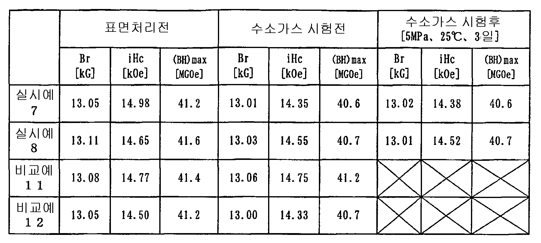
표 8에, 표면처리전 및 수소가스 시험 전후의 자석의 자기 특성을 나타내었다. 표면처리전 및 수소가스 시험 전후에, 실시예 7, 8은, 거의 자기 특성의 변화가 없었다. 이것으로부터, 실시예 7, 8에 있어서, 표면처리에 의한 자기 특성의 열화 및 수소취성이 없었던 것을 알 수 있다. 비교예 11, 12는, 수소 처리에 의해 분쇄되어 버렸기 때문에, 수소 처리후의 자기 특성은, 측정 불능이었다. Table 8 shows the magnetic properties of the magnet before the surface treatment and before and after the hydrogen gas test. Before the surface treatment and before and after the hydrogen gas test, Examples 7 and 8 had almost no change in magnetic properties. This shows that in Example 7, 8, there was no deterioration of magnetic properties and hydrogen embrittlement by surface treatment. Since Comparative Examples 11 and 12 were crushed by the hydrogen treatment, the magnetic properties after the hydrogen treatment could not be measured.
표 7, 8의 결과로부터, 비교예에서는, 수소가스 시험에 의해 수소취성이 일 어난 것에 반하여, 실시예에서는, 수소가스 시험에 의해 수소취성이 일어나지 않았다. 즉, 표면처리에 의해 자기 특성이 열화되는 일 없이, 내수소성이 향상된 것을 알 수 있다. From the results of Tables 7 and 8, in the comparative example, hydrogen embrittlement occurred in the hydrogen gas test, whereas in the examples, hydrogen embrittlement did not occur in the hydrogen gas test. That is, it turns out that hydrogen resistance improves, without deteriorating a magnetic characteristic by surface treatment.
이상과 같이, 본 발명의 Sm2Co17계 또는 R2Fe14B계 소결 자석에 의해, 수소 분위기중에서도, 수소취성을 일으키지 않아, 모터 등에 사용할 수 있는 희토류 소결 자석을 얻는 것이 가능해진다. As described above, the Sm 2 Co 17 type or R 2 Fe 14 B type sintered magnet of the present invention makes it possible to obtain a rare earth sintered magnet which can be used in a motor or the like without generating hydrogen embrittlement even in a hydrogen atmosphere.
Claims (12)
Applications Claiming Priority (9)
| Application Number | Priority Date | Filing Date | Title |
|---|---|---|---|
| JP2001399174A JP3904061B2 (en) | 2001-12-28 | 2001-12-28 | Manufacturing method of rare earth sintered magnet |
| JPJP-P-2001-00399177 | 2001-12-28 | ||
| JP2001399176 | 2001-12-28 | ||
| JPJP-P-2001-00399174 | 2001-12-28 | ||
| JP2001399175 | 2001-12-28 | ||
| JPJP-P-2001-00399175 | 2001-12-28 | ||
| JPJP-P-2001-00399176 | 2001-12-28 | ||
| JP2001399177A JP3904062B2 (en) | 2001-12-28 | 2001-12-28 | Rare earth sintered magnet |
| PCT/JP2002/013430 WO2003058648A1 (en) | 2001-12-28 | 2002-12-24 | Rare earth element sintered magnet and method for producing rare earth element sintered magnet |
Related Child Applications (1)
| Application Number | Title | Priority Date | Filing Date |
|---|---|---|---|
| KR1020077008306A Division KR100788330B1 (en) | 2001-12-28 | 2002-12-24 | Rare earth element sintered magnet and method for producing rare earth element sintered magnet |
Publications (2)
| Publication Number | Publication Date |
|---|---|
| KR20040073513A KR20040073513A (en) | 2004-08-19 |
| KR100746897B1 true KR100746897B1 (en) | 2007-08-07 |
Family
ID=27482755
Family Applications (2)
| Application Number | Title | Priority Date | Filing Date |
|---|---|---|---|
| KR1020047010039A KR100746897B1 (en) | 2001-12-28 | 2002-12-24 | Rare earth element sintered magnet and method for producing rare earth element sintered magnet |
| KR1020077008306A KR100788330B1 (en) | 2001-12-28 | 2002-12-24 | Rare earth element sintered magnet and method for producing rare earth element sintered magnet |
Family Applications After (1)
| Application Number | Title | Priority Date | Filing Date |
|---|---|---|---|
| KR1020077008306A KR100788330B1 (en) | 2001-12-28 | 2002-12-24 | Rare earth element sintered magnet and method for producing rare earth element sintered magnet |
Country Status (7)
| Country | Link |
|---|---|
| US (1) | US7438768B2 (en) |
| EP (1) | EP1467385B1 (en) |
| KR (2) | KR100746897B1 (en) |
| CN (1) | CN1299300C (en) |
| DE (1) | DE60237114D1 (en) |
| TW (1) | TWI282101B (en) |
| WO (1) | WO2003058648A1 (en) |
Families Citing this family (33)
| Publication number | Priority date | Publication date | Assignee | Title |
|---|---|---|---|---|
| US7753079B2 (en) | 2005-06-17 | 2010-07-13 | Masco Corporation Of Indiana | Magnetic coupling for sprayheads |
| US7909061B2 (en) | 2005-06-17 | 2011-03-22 | Masco Corporation Of Indiana | Magnetic coupling for sprayheads |
| US9315975B2 (en) | 2005-06-17 | 2016-04-19 | Delta Faucet Company | Magnetic coupling for sprayheads |
| US8105444B2 (en) * | 2007-05-30 | 2012-01-31 | Shin-Etsu Chemical Co., Ltd. | Process for producing highly anticorrosive rare earth permanent magnet and method of using the same |
| DE102009008209A1 (en) * | 2009-02-10 | 2010-08-19 | Carl Zeiss Smt Ag | Actuator with at least one magnet for a projection exposure apparatus and projection exposure apparatus with a magnet and manufacturing method thereof |
| CN102039407B (en) * | 2009-10-14 | 2014-09-17 | 三环瓦克华(北京)磁性器件有限公司 | Method for decreasing harmful gases in process of sintering sintered neodymium iron boron (NdFeB) magnet |
| US8627844B2 (en) * | 2009-10-30 | 2014-01-14 | Masco Corporation Of Indiana | Magnetic escutcheon mounting assembly |
| US8567430B2 (en) | 2009-10-30 | 2013-10-29 | Masco Corporation Of Indiana | Magnetic coupling for faucet handle |
| JP5013031B2 (en) * | 2010-09-30 | 2012-08-29 | 日立金属株式会社 | Method for forming electrolytic copper plating film on surface of rare earth permanent magnet |
| EP2523316B8 (en) * | 2011-05-11 | 2014-11-19 | ALSTOM Renewable Technologies | Generator rotor, assembly method and related insertion tool |
| US9284723B2 (en) | 2012-07-27 | 2016-03-15 | Kohler Co. | Magnetic docking faucet |
| US9181685B2 (en) | 2012-07-27 | 2015-11-10 | Kohler Co. | Magnetic docking faucet |
| EP2696219B1 (en) | 2012-08-06 | 2017-01-04 | Ampass-Explorer Corp. | Header device for improving the reception quality of a material detector device |
| KR102283172B1 (en) | 2015-02-03 | 2021-07-29 | 엘지이노텍 주식회사 | Rare earth magnet and motor including the same |
| CN104637642B (en) * | 2015-02-13 | 2017-03-08 | 宁波宁港永磁材料有限公司 | A kind of SmCo sintered permanent magnet material and preparation method thereof |
| CN106024242A (en) * | 2016-07-14 | 2016-10-12 | 安徽万磁电子有限公司 | Corrosion-resistant nickel-plated neodymium-iron-boron raw material powder and preparation method thereof |
| US10672544B2 (en) | 2016-12-06 | 2020-06-02 | Tdk Corporation | R-T-B based permanent magnet |
| US10672545B2 (en) | 2016-12-06 | 2020-06-02 | Tdk Corporation | R-T-B based permanent magnet |
| CN109841367B (en) * | 2017-11-29 | 2020-12-25 | 有研稀土新材料股份有限公司 | Rare earth bonded magnetic powder, method for producing same, and bonded magnet |
| CN109208047A (en) * | 2018-08-08 | 2019-01-15 | 北京麦戈龙科技有限公司 | A kind of coating structure of Sintered NdFeB magnet and preparation method thereof |
| US10916269B2 (en) | 2019-02-19 | 2021-02-09 | Western Digital Technologies, Inc. | Magnet for motor of magnetic storage device |
| CN110136908B (en) * | 2019-05-07 | 2021-03-05 | 宁波科星材料科技有限公司 | Rare earth permanent magnet composite material and preparation method thereof |
| KR102187561B1 (en) * | 2019-10-25 | 2020-12-07 | 한국생산기술연구원 | Method for manufacturing nd-fe-b group permanent magnet containing titanium |
| KR102189985B1 (en) * | 2019-10-25 | 2020-12-11 | 한국생산기술연구원 | Method for manufacturing nd-fe-b group permanent magnet and nd-fe-b group permanent using thereof |
| CN111313571B (en) * | 2019-11-29 | 2022-01-28 | 南京安德海睿智能科技有限公司 | Hydrogen-resistant motor based on rare earth permanent magnet |
| CN111243804B (en) * | 2019-11-29 | 2023-10-17 | 南京安德海睿智能科技有限公司 | Rare earth permanent magnet with hydrogen resistance and preparation method thereof |
| CN111128502B (en) * | 2019-12-04 | 2022-03-25 | 湖南航天磁电有限责任公司 | Preparation method of super-corrosion-resistant high-performance sintered samarium-cobalt magnet |
| CN110993235B (en) * | 2019-12-26 | 2020-11-20 | 福建省长汀卓尔科技股份有限公司 | High-iron low-copper samarium-cobalt permanent magnet material and preparation method thereof |
| CN111270280B (en) * | 2020-01-23 | 2021-03-30 | 北京麦戈龙科技有限公司 | Coating structure of sintered neodymium-iron-boron magnet and preparation method thereof |
| CN112017831B (en) * | 2020-08-20 | 2022-12-06 | 合肥工业大学 | Preparation method of high-toughness samarium-cobalt magnet |
| CN113451038B (en) * | 2021-06-07 | 2023-05-02 | 杭州永磁集团有限公司 | Preparation method of samarium cobalt permanent magnet suitable for high-temperature high-pressure pure hydrogen environment |
| CN113539606B (en) * | 2021-06-16 | 2023-05-09 | 杭州永磁集团有限公司 | High-temperature-resistant and hydrogen-resistant samarium cobalt permanent magnet motor |
| WO2023140753A1 (en) * | 2022-01-19 | 2023-07-27 | Общество С Ограниченной Ответственностью "Ампермагнит" | Method for manufacturing segmented permanent magnets from low-grade magnetically hard sintered raw material |
Citations (5)
| Publication number | Priority date | Publication date | Assignee | Title |
|---|---|---|---|---|
| JPH01304713A (en) * | 1988-06-02 | 1989-12-08 | Shin Etsu Chem Co Ltd | Manufacture of corrosion-resistant rare earth magnet |
| JPH04288804A (en) * | 1991-03-18 | 1992-10-13 | Tdk Corp | Permanent magnet and manufacture thereof |
| JPH06108190A (en) * | 1992-09-25 | 1994-04-19 | Shin Etsu Chem Co Ltd | Rare earth permanent magnet alloy |
| JPH06140218A (en) * | 1992-10-29 | 1994-05-20 | Toshiba Corp | Shock-resistant rare-earth cobalt magnet and manufacture thereof |
| JP2001167917A (en) * | 1999-09-27 | 2001-06-22 | Sumitomo Special Metals Co Ltd | R-Fe-B PERMANENT MAGNET AND MANUFACTURING METHOD OF THE SAME |
Family Cites Families (24)
| Publication number | Priority date | Publication date | Assignee | Title |
|---|---|---|---|---|
| JPS5766604A (en) | 1980-10-13 | 1982-04-22 | Toshiba Corp | Surface treatment for rare-earth cobalt magnet |
| JPS5681908A (en) * | 1980-10-14 | 1981-07-04 | Seiko Epson Corp | Rare earth metal intermetallic compound sintered magnet having covered surface |
| CA1316375C (en) * | 1982-08-21 | 1993-04-20 | Masato Sagawa | Magnetic materials and permanent magnets |
| JPS59161610A (en) | 1983-03-03 | 1984-09-12 | Ebara Corp | Refuse incinerator |
| CN1007847B (en) * | 1984-12-24 | 1990-05-02 | 住友特殊金属株式会社 | Process for producing magnets having improved corrosion resistance |
| FI861898A (en) * | 1986-05-07 | 1987-11-08 | Outokumpu Oy | FOERFARANDE FOER HANTERING AV METALLSTYCKEN. |
| JP2576671B2 (en) | 1989-07-31 | 1997-01-29 | 三菱マテリアル株式会社 | Rare earth-Fe-B permanent magnet powder and bonded magnet with excellent magnetic anisotropy and corrosion resistance |
| JPH05226125A (en) * | 1992-02-14 | 1993-09-03 | Kobe Steel Ltd | Manufacture of highly corrosion-resistant rare-earth magnet |
| US5382303A (en) * | 1992-04-13 | 1995-01-17 | Sps Technologies, Inc. | Permanent magnets and methods for their fabrication |
| JPH06120014A (en) | 1992-10-05 | 1994-04-28 | Tokin Corp | Surface treatment of rare earth-obalt magnet alloy |
| JPH08181016A (en) | 1994-12-22 | 1996-07-12 | Tokin Corp | Samarium cobalt magnet and its manufacturing method |
| US5876518A (en) * | 1995-02-23 | 1999-03-02 | Hitachi Metals, Ltd. | R-T-B-based, permanent magnet, method for producing same, and permanent magnet-type motor and actuator comprising same |
| EP0811994B1 (en) | 1995-12-25 | 2003-10-08 | Sumitomo Special Metals Company Limited | Permanent magnet for ultrahigh vacuum application and method for manufacturing the same |
| JP2000040610A (en) * | 1998-07-24 | 2000-02-08 | Sumitomo Metal Mining Co Ltd | Film coated rare earth magnet |
| EP0984460B1 (en) * | 1998-08-31 | 2004-03-17 | Sumitomo Special Metals Co., Ltd. | Fe-B-R based permanent magnet having corrosion-resistant film, and process for producing the same |
| JP3423299B2 (en) * | 1998-08-31 | 2003-07-07 | 住友特殊金属株式会社 | Fe-BR type permanent magnet having corrosion-resistant film |
| JP3351768B2 (en) * | 1998-08-31 | 2002-12-03 | 住友特殊金属株式会社 | Method for producing Fe-BR based permanent magnet having corrosion resistant film |
| JP2001076914A (en) * | 1998-12-17 | 2001-03-23 | Sumitomo Special Metals Co Ltd | Rare-earth based permanent magnet and manufacture thereof |
| JP3278647B2 (en) * | 1999-01-27 | 2002-04-30 | 住友特殊金属株式会社 | Rare earth bonded magnet |
| JP2000285415A (en) | 1999-03-29 | 2000-10-13 | Sumitomo Metal Ind Ltd | Manufacture for ferromagnetic tunnel junction magnetoresistive element |
| JP4678118B2 (en) * | 2000-07-17 | 2011-04-27 | 日立金属株式会社 | Coated R-T-B magnet and method for manufacturing the same |
| US6623541B2 (en) * | 2000-07-31 | 2003-09-23 | Shin-Etsu Chemical Co., Ltd. | Sintered rare earth magnet and making method |
| JP4081642B2 (en) | 2000-07-31 | 2008-04-30 | 信越化学工業株式会社 | Rare earth sintered magnet and manufacturing method thereof |
| EP1180771B1 (en) * | 2000-08-11 | 2004-10-27 | Neomax Co., Ltd. | Rare earth metal-based permanent magnet having corrosion-resistant film and method for producing the same |
-
2002
- 2002-12-24 KR KR1020047010039A patent/KR100746897B1/en not_active IP Right Cessation
- 2002-12-24 DE DE60237114T patent/DE60237114D1/en not_active Expired - Lifetime
- 2002-12-24 US US10/500,074 patent/US7438768B2/en active Active
- 2002-12-24 WO PCT/JP2002/013430 patent/WO2003058648A1/en active Application Filing
- 2002-12-24 EP EP02806069A patent/EP1467385B1/en not_active Expired - Fee Related
- 2002-12-24 KR KR1020077008306A patent/KR100788330B1/en not_active IP Right Cessation
- 2002-12-24 CN CNB028276272A patent/CN1299300C/en not_active Expired - Fee Related
- 2002-12-26 TW TW091137527A patent/TWI282101B/en not_active IP Right Cessation
Patent Citations (5)
| Publication number | Priority date | Publication date | Assignee | Title |
|---|---|---|---|---|
| JPH01304713A (en) * | 1988-06-02 | 1989-12-08 | Shin Etsu Chem Co Ltd | Manufacture of corrosion-resistant rare earth magnet |
| JPH04288804A (en) * | 1991-03-18 | 1992-10-13 | Tdk Corp | Permanent magnet and manufacture thereof |
| JPH06108190A (en) * | 1992-09-25 | 1994-04-19 | Shin Etsu Chem Co Ltd | Rare earth permanent magnet alloy |
| JPH06140218A (en) * | 1992-10-29 | 1994-05-20 | Toshiba Corp | Shock-resistant rare-earth cobalt magnet and manufacture thereof |
| JP2001167917A (en) * | 1999-09-27 | 2001-06-22 | Sumitomo Special Metals Co Ltd | R-Fe-B PERMANENT MAGNET AND MANUFACTURING METHOD OF THE SAME |
Also Published As
| Publication number | Publication date |
|---|---|
| US20050028890A1 (en) | 2005-02-10 |
| EP1467385A4 (en) | 2007-06-27 |
| CN1299300C (en) | 2007-02-07 |
| KR20070049245A (en) | 2007-05-10 |
| US7438768B2 (en) | 2008-10-21 |
| KR100788330B1 (en) | 2007-12-27 |
| EP1467385A1 (en) | 2004-10-13 |
| EP1467385B1 (en) | 2010-07-21 |
| WO2003058648A1 (en) | 2003-07-17 |
| TW200301492A (en) | 2003-07-01 |
| KR20040073513A (en) | 2004-08-19 |
| TWI282101B (en) | 2007-06-01 |
| DE60237114D1 (en) | 2010-09-02 |
| CN1618108A (en) | 2005-05-18 |
Similar Documents
| Publication | Publication Date | Title |
|---|---|---|
| KR100746897B1 (en) | Rare earth element sintered magnet and method for producing rare earth element sintered magnet | |
| RU2417138C2 (en) | Method of producing rare-earth permanent magnet material | |
| RU2417139C2 (en) | Method of producing rare-earth permanent magnet material | |
| KR101353186B1 (en) | Method for Preparing Rare Earth Permanent Magnet Material | |
| RU2389098C2 (en) | Functional-gradient rare-earth permanent magnet | |
| KR101855530B1 (en) | Rare earth permanent magnet and their preparation | |
| US8557057B2 (en) | Rare earth permanent magnet and its preparation | |
| US20140311291A1 (en) | R-t-b based sintered magnet | |
| JP4003067B2 (en) | Rare earth sintered magnet | |
| JP4003066B2 (en) | Manufacturing method of rare earth sintered magnet | |
| JP5024531B2 (en) | How to use rare earth sintered magnets | |
| US5082745A (en) | Rare earth based permanent magnet having corrosion-resistant surface film and method for the preparation thereof | |
| US7740716B2 (en) | Rare earth sintered magnet | |
| US6623541B2 (en) | Sintered rare earth magnet and making method | |
| EP0923087B1 (en) | Corrosion-resistant permanent magnet and method for manufacturing the same | |
| JP4919048B2 (en) | How to use rare earth sintered magnets | |
| JP3904062B2 (en) | Rare earth sintered magnet | |
| JP4296442B2 (en) | Method for preventing hydrogen embrittlement of rare earth sintered magnets | |
| JP2007288205A (en) | Method for improving anti-hydrogen property of rare earth sintered magnet | |
| JP4081642B2 (en) | Rare earth sintered magnet and manufacturing method thereof | |
| JP3904061B2 (en) | Manufacturing method of rare earth sintered magnet | |
| JP3641477B2 (en) | R-T-B permanent magnet | |
| JPH0237702A (en) | R-fe-b-m sintered magnet |
Legal Events
| Date | Code | Title | Description |
|---|---|---|---|
| A201 | Request for examination | ||
| E902 | Notification of reason for refusal | ||
| A107 | Divisional application of patent | ||
| E701 | Decision to grant or registration of patent right | ||
| GRNT | Written decision to grant | ||
| G170 | Re-publication after modification of scope of protection [patent] | ||
| FPAY | Annual fee payment |
Payment date: 20120724 Year of fee payment: 6 |
|
| FPAY | Annual fee payment |
Payment date: 20130719 Year of fee payment: 7 |
|
| FPAY | Annual fee payment |
Payment date: 20140721 Year of fee payment: 8 |
|
| FPAY | Annual fee payment |
Payment date: 20150716 Year of fee payment: 9 |
|
| FPAY | Annual fee payment |
Payment date: 20160630 Year of fee payment: 10 |
|
| FPAY | Annual fee payment |
Payment date: 20170720 Year of fee payment: 11 |
|
| LAPS | Lapse due to unpaid annual fee |