JP7589151B2 - 少なくとも2つのブレーキパッドおよび少なくとも1つのスプリングのアセンブリ - Google Patents
少なくとも2つのブレーキパッドおよび少なくとも1つのスプリングのアセンブリ Download PDFInfo
- Publication number
- JP7589151B2 JP7589151B2 JP2021536008A JP2021536008A JP7589151B2 JP 7589151 B2 JP7589151 B2 JP 7589151B2 JP 2021536008 A JP2021536008 A JP 2021536008A JP 2021536008 A JP2021536008 A JP 2021536008A JP 7589151 B2 JP7589151 B2 JP 7589151B2
- Authority
- JP
- Japan
- Prior art keywords
- spring
- pad
- edge
- pads
- assembly
- Prior art date
- Legal status (The legal status is an assumption and is not a legal conclusion. Google has not performed a legal analysis and makes no representation as to the accuracy of the status listed.)
- Active
Links
Images


Classifications
-
- F—MECHANICAL ENGINEERING; LIGHTING; HEATING; WEAPONS; BLASTING
- F16—ENGINEERING ELEMENTS AND UNITS; GENERAL MEASURES FOR PRODUCING AND MAINTAINING EFFECTIVE FUNCTIONING OF MACHINES OR INSTALLATIONS; THERMAL INSULATION IN GENERAL
- F16D—COUPLINGS FOR TRANSMITTING ROTATION; CLUTCHES; BRAKES
- F16D65/00—Parts or details
- F16D65/02—Braking members; Mounting thereof
- F16D65/04—Bands, shoes or pads; Pivots or supporting members therefor
- F16D65/092—Bands, shoes or pads; Pivots or supporting members therefor for axially-engaging brakes, e.g. disc brakes
- F16D65/095—Pivots or supporting members therefor
- F16D65/097—Resilient means interposed between pads and supporting members or other brake parts
- F16D65/0972—Resilient means interposed between pads and supporting members or other brake parts transmitting brake reaction force, e.g. elements interposed between torque support plate and pad
-
- F—MECHANICAL ENGINEERING; LIGHTING; HEATING; WEAPONS; BLASTING
- F16—ENGINEERING ELEMENTS AND UNITS; GENERAL MEASURES FOR PRODUCING AND MAINTAINING EFFECTIVE FUNCTIONING OF MACHINES OR INSTALLATIONS; THERMAL INSULATION IN GENERAL
- F16D—COUPLINGS FOR TRANSMITTING ROTATION; CLUTCHES; BRAKES
- F16D65/00—Parts or details
- F16D65/02—Braking members; Mounting thereof
- F16D65/04—Bands, shoes or pads; Pivots or supporting members therefor
- F16D65/092—Bands, shoes or pads; Pivots or supporting members therefor for axially-engaging brakes, e.g. disc brakes
- F16D65/095—Pivots or supporting members therefor
- F16D65/097—Resilient means interposed between pads and supporting members or other brake parts
- F16D65/0973—Resilient means interposed between pads and supporting members or other brake parts not subjected to brake forces
- F16D65/0974—Resilient means interposed between pads and supporting members or other brake parts not subjected to brake forces acting on or in the vicinity of the pad rim in a direction substantially transverse to the brake disc axis
- F16D65/0975—Springs made from wire
-
- F—MECHANICAL ENGINEERING; LIGHTING; HEATING; WEAPONS; BLASTING
- F16—ENGINEERING ELEMENTS AND UNITS; GENERAL MEASURES FOR PRODUCING AND MAINTAINING EFFECTIVE FUNCTIONING OF MACHINES OR INSTALLATIONS; THERMAL INSULATION IN GENERAL
- F16D—COUPLINGS FOR TRANSMITTING ROTATION; CLUTCHES; BRAKES
- F16D55/00—Brakes with substantially-radial braking surfaces pressed together in axial direction, e.g. disc brakes
- F16D55/02—Brakes with substantially-radial braking surfaces pressed together in axial direction, e.g. disc brakes with axially-movable discs or pads pressed against axially-located rotating members
- F16D55/22—Brakes with substantially-radial braking surfaces pressed together in axial direction, e.g. disc brakes with axially-movable discs or pads pressed against axially-located rotating members by clamping an axially-located rotating disc between movable braking members, e.g. movable brake discs or brake pads
- F16D55/224—Brakes with substantially-radial braking surfaces pressed together in axial direction, e.g. disc brakes with axially-movable discs or pads pressed against axially-located rotating members by clamping an axially-located rotating disc between movable braking members, e.g. movable brake discs or brake pads with a common actuating member for the braking members
- F16D55/225—Brakes with substantially-radial braking surfaces pressed together in axial direction, e.g. disc brakes with axially-movable discs or pads pressed against axially-located rotating members by clamping an axially-located rotating disc between movable braking members, e.g. movable brake discs or brake pads with a common actuating member for the braking members the braking members being brake pads
- F16D55/226—Brakes with substantially-radial braking surfaces pressed together in axial direction, e.g. disc brakes with axially-movable discs or pads pressed against axially-located rotating members by clamping an axially-located rotating disc between movable braking members, e.g. movable brake discs or brake pads with a common actuating member for the braking members the braking members being brake pads in which the common actuating member is moved axially, e.g. floating caliper disc brakes
- F16D55/2265—Brakes with substantially-radial braking surfaces pressed together in axial direction, e.g. disc brakes with axially-movable discs or pads pressed against axially-located rotating members by clamping an axially-located rotating disc between movable braking members, e.g. movable brake discs or brake pads with a common actuating member for the braking members the braking members being brake pads in which the common actuating member is moved axially, e.g. floating caliper disc brakes the axial movement being guided by one or more pins engaging bores in the brake support or the brake housing
- F16D55/227—Brakes with substantially-radial braking surfaces pressed together in axial direction, e.g. disc brakes with axially-movable discs or pads pressed against axially-located rotating members by clamping an axially-located rotating disc between movable braking members, e.g. movable brake discs or brake pads with a common actuating member for the braking members the braking members being brake pads in which the common actuating member is moved axially, e.g. floating caliper disc brakes the axial movement being guided by one or more pins engaging bores in the brake support or the brake housing by two or more pins
-
- F—MECHANICAL ENGINEERING; LIGHTING; HEATING; WEAPONS; BLASTING
- F16—ENGINEERING ELEMENTS AND UNITS; GENERAL MEASURES FOR PRODUCING AND MAINTAINING EFFECTIVE FUNCTIONING OF MACHINES OR INSTALLATIONS; THERMAL INSULATION IN GENERAL
- F16D—COUPLINGS FOR TRANSMITTING ROTATION; CLUTCHES; BRAKES
- F16D65/00—Parts or details
- F16D65/0006—Noise or vibration control
-
- F—MECHANICAL ENGINEERING; LIGHTING; HEATING; WEAPONS; BLASTING
- F16—ENGINEERING ELEMENTS AND UNITS; GENERAL MEASURES FOR PRODUCING AND MAINTAINING EFFECTIVE FUNCTIONING OF MACHINES OR INSTALLATIONS; THERMAL INSULATION IN GENERAL
- F16D—COUPLINGS FOR TRANSMITTING ROTATION; CLUTCHES; BRAKES
- F16D65/00—Parts or details
- F16D65/02—Braking members; Mounting thereof
- F16D65/04—Bands, shoes or pads; Pivots or supporting members therefor
- F16D65/092—Bands, shoes or pads; Pivots or supporting members therefor for axially-engaging brakes, e.g. disc brakes
- F16D65/095—Pivots or supporting members therefor
- F16D65/097—Resilient means interposed between pads and supporting members or other brake parts
- F16D65/0973—Resilient means interposed between pads and supporting members or other brake parts not subjected to brake forces
- F16D65/0974—Resilient means interposed between pads and supporting members or other brake parts not subjected to brake forces acting on or in the vicinity of the pad rim in a direction substantially transverse to the brake disc axis
- F16D65/0977—Springs made from sheet metal
-
- F—MECHANICAL ENGINEERING; LIGHTING; HEATING; WEAPONS; BLASTING
- F16—ENGINEERING ELEMENTS AND UNITS; GENERAL MEASURES FOR PRODUCING AND MAINTAINING EFFECTIVE FUNCTIONING OF MACHINES OR INSTALLATIONS; THERMAL INSULATION IN GENERAL
- F16D—COUPLINGS FOR TRANSMITTING ROTATION; CLUTCHES; BRAKES
- F16D65/00—Parts or details
- F16D65/38—Slack adjusters
- F16D65/40—Slack adjusters mechanical
- F16D65/52—Slack adjusters mechanical self-acting in one direction for adjusting excessive play
-
- F—MECHANICAL ENGINEERING; LIGHTING; HEATING; WEAPONS; BLASTING
- F16—ENGINEERING ELEMENTS AND UNITS; GENERAL MEASURES FOR PRODUCING AND MAINTAINING EFFECTIVE FUNCTIONING OF MACHINES OR INSTALLATIONS; THERMAL INSULATION IN GENERAL
- F16D—COUPLINGS FOR TRANSMITTING ROTATION; CLUTCHES; BRAKES
- F16D55/00—Brakes with substantially-radial braking surfaces pressed together in axial direction, e.g. disc brakes
- F16D2055/0004—Parts or details of disc brakes
- F16D2055/0016—Brake calipers
- F16D2055/0029—Retraction devices
-
- F—MECHANICAL ENGINEERING; LIGHTING; HEATING; WEAPONS; BLASTING
- F16—ENGINEERING ELEMENTS AND UNITS; GENERAL MEASURES FOR PRODUCING AND MAINTAINING EFFECTIVE FUNCTIONING OF MACHINES OR INSTALLATIONS; THERMAL INSULATION IN GENERAL
- F16D—COUPLINGS FOR TRANSMITTING ROTATION; CLUTCHES; BRAKES
- F16D2127/00—Auxiliary mechanisms
- F16D2127/02—Release mechanisms
-
- F—MECHANICAL ENGINEERING; LIGHTING; HEATING; WEAPONS; BLASTING
- F16—ENGINEERING ELEMENTS AND UNITS; GENERAL MEASURES FOR PRODUCING AND MAINTAINING EFFECTIVE FUNCTIONING OF MACHINES OR INSTALLATIONS; THERMAL INSULATION IN GENERAL
- F16D—COUPLINGS FOR TRANSMITTING ROTATION; CLUTCHES; BRAKES
- F16D65/00—Parts or details
- F16D65/005—Components of axially engaging brakes not otherwise provided for
- F16D65/0068—Brake calipers
-
- F—MECHANICAL ENGINEERING; LIGHTING; HEATING; WEAPONS; BLASTING
- F16—ENGINEERING ELEMENTS AND UNITS; GENERAL MEASURES FOR PRODUCING AND MAINTAINING EFFECTIVE FUNCTIONING OF MACHINES OR INSTALLATIONS; THERMAL INSULATION IN GENERAL
- F16D—COUPLINGS FOR TRANSMITTING ROTATION; CLUTCHES; BRAKES
- F16D65/00—Parts or details
- F16D65/02—Braking members; Mounting thereof
- F16D65/12—Discs; Drums for disc brakes
Landscapes
- Engineering & Computer Science (AREA)
- General Engineering & Computer Science (AREA)
- Mechanical Engineering (AREA)
- Braking Arrangements (AREA)
Description
-パッドの振動を低減すること、
-ブレーキがかかっていない状態で、パッドとブレーキディスクの間の望ましくない接触に起因する残留制動トルク(残留トルク)を低減または除去するために、パッドをブレーキディスクから離すこと、
-パッドの摩擦ライニングの均一な摩耗を得ること、
である。
-径方向内向きに、またはディスク回転軸10に向かってブレーキディスク3に面するように適合された内側下エッジ25と、
-径方向外向きに、またはディスク回転軸10と反対側にブレーキディスク3に面するように適合された内側上エッジ26と、
を含む。
-内側下エッジ25、および
-上側のスプリング連結プレート部のエッジ29と、
排他的に常に接触している。
-キャリパ2のポケット9に当接して挿入されるように適合された当接壁14であって、当接壁14は、角張った形状であり、したがって、キャリパ2のポケット9の2つの異なる表面に取り付けられた金属シートに突き当たるように適合された第1の当接壁14’および第2の当接壁14’’を形成する、当接壁14;および
-連結シート13、
を形成する。
-第1の斜部または第1の傾斜部21’と、
-第2の斜部または第2の傾斜部21’’と、
-戻り部22と、
を含む。
-上述した実施形態のいずれか1つによる、少なくとも2つのパッド6および少なくとも1つのスプリング15を含むアセンブリ100;
-キャリパ2;および、
-ブレーキディスク3、
を含むディスクブレーキ1に関する。
-上述の実施形態のいずれか1つによるアセンブリを提供するステップと、
-パッド6の摩擦材料8の摩耗時に、スプリング15をスプリング連結プレート部37を中心にヒンジのように回転させ、スプリング15を内側下エッジ25および上側スプリング連結プレート部エッジ29に対してスライドさせて、ブレーキ動作が停止したときに、パッド6をブレーキから遠ざけるための弾性バイアスを、軸方向A-Aに実質的にグローバルに向けて印加するステップと、が含まれる。
2 キャリパ
3 ブレーキディスク
4 ブラケット
5 制動バンド
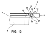
6 パッド
7 支持プレート
8 摩擦材料
9 ポケット
10 (ブレーキディスクの)回転軸
11 油圧シリンダ-ピストン
12 (パッドの)耳部
13 連結シート
14 当接壁
14’ 第1の当接壁
14’’ 第2の当接壁
15 スプリング
16 (スプリングの)対称面
17 連結部またはスプリングアーム
18 ブリッジ部
19 第1のコネクタ
21’ 第1の斜部または傾斜部
21’’ 第2の斜部または傾斜部
22 戻り部
23 フック形状の端部
24 第2のコネクタ
25 内側下エッジ
26 内側上エッジ
27 上面
28 外側上エッジ
29 上側スプリング連結プレート部エッジ
30 内側パッド連結部側
31 下側スプリング連結プレート部エッジ
32 上側スプリングシートエッジ
33 内側スプリングシート
34 下側スプリングシートエッジ
35 第1の接続ループ
36 ディスクブレーキ制動面
37 スプリング連結プレート部
100 パッドスプリングアセンブリ
A-A 軸方向
R-R 径方向
C-C 周方向
T-T 接線方向
Claims (14)
- アセンブリであって、前記アセンブリは、
支持プレート(7)と摩擦材料コーティング(8)を有する少なくとも2つのパッド(6)を含み、
前記少なくとも2つのパッド(6)のそれぞれは、前記少なくとも2つのパッド(6)のそれぞれがディスクブレーキ(1)のブレーキディスク(3)の側に、対向する制動面(36)に面して配置できるように、キャリパ(2)のポケット(9)に収容されるように適合されており、
前記ブレーキディスク(3)は、回転軸(10)に平行な軸方向(A-A)と、前記回転軸(10)に直交する径方向(R-R)と、前記軸方向(A-A)および前記径方向(R-R)に直交する周方向(C-C)と、前記径方向(R-R)および前記周方向(C-C)にそれらの交差点で直交する接線方向T-Tとを画定する前記回転軸(10)を中心に回転するように適合されたロータであり、
前記アセンブリはまた、
前記ディスクブレーキ(3)を跨いで配置される形状の、少なくとも1つのスプリング(15)を含み、
前記スプリング(15)は、前記パッド(6)を前記ブレーキディスク(3)から弾性的に離すように、前記パッド(6)に弾性的なバイアスをかけ、
前記少なくとも1つのスプリング(15)は、前記パッド(6)にのみ直接接続されるように構成され、
前記支持プレート(7)は、少なくとも1つのプレート連結部(37)を含み、
前記軸方向(A-A)および前記径方向(R-R)を含む平面上の前記プレート連結部(37)の一セクションにおいて、前記プレート連結部(37)は、
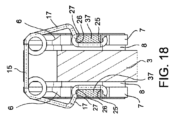
-径方向内向きに、またはディスク回転軸(10)に向かって前記ブレーキディスク(3)に面するように適合された内側下エッジ(25)と、
-内側上エッジ(26)、上面(27)、外側上エッジ(28)によって形成される上側スプリング連結プレート部エッジ(29)と、を含み、
前記内側上エッジ(26)は、径方向外向きに、または前記ディスク回転軸(10)と反対側に前記ブレーキディスク(3)に面するように適合され、
-前記内側上エッジ(26)は、前記ディスク回転軸(10)に平行な前記軸方向(A-A)に従って、直接上面(27)に続いており、したがって前記上側スプリング連結プレート部エッジ(29)を形成し、
前記スプリング(15)は、
-前記内側下エッジ(25)と、
-前記上側スプリング連結プレート部エッジ(29)のみと常に接触している、
アセンブリ(100)。 - 前記スプリング(15)が一体に作られた線状のスプリングである、又は前記スプリング(15)が円形の断面を有する線状のスプリングである、および/または前記スプリング(15)は、一体型のスプリングであり、
前記スプリング(15)は、前記内側下エッジ(25)と前記上側スプリング連結プレート部のエッジ(29)のみと点または線で常に接触している、
請求項1に記載のアセンブリ(100)。 - 前記内側上エッジ(26)が、前記内側下エッジ(25)とは反対側の側面に径方向に配置され、
前記内側上エッジ(26)は、前記ディスク回転軸(10)に平行な軸方向(A-A)に従って、上面(27)に直接続いており、
前記上面(27)は、前記ブレーキディスク(3)と反対方向に回転するように適合された外側上エッジ(28)に続いており、
前記スプリング(15)は、前記内側上エッジ(26)または前記上面(27)または前記外側上エッジ(28)と常に接触している、
請求項1または2に記載のアセンブリ(100)。 - 前記スプリング(15)は、前記少なくとも2つのパッド(6)以外のものに接触することを回避し、それにより前記キャリパ(2)への接続を回避し、その上の弾性反応の全部または一部を緩和する、および/または、
前記アセンブリ(100)は、前記パッド(6)を弾性的にバイアスするように、前記ブレーキディスク(3)を跨いで配置されるように適合された2つのスプリング(15)を含み、前記2つのスプリング(15)の両方が、前記パッド(6)にのみ直接接続されるように構成される、
請求項1~3のいずれか1つに記載のアセンブリ(100)。 - 前記パッド(6)の前記支持プレート(7)は実質的に長方形の形状であり、前記支持プレート(7)は、周方向C-Cに、前記支持プレート(7)の外側に向かって延びる2つの耳部(12)を形成する、
請求項1~4のいずれか1つに記載のアセンブリ(100)。 - 前記2つの耳部(12)のそれぞれは、
-前記キャリパ(2)の前記ポケット(9)に当接して挿入されるように適合された当接壁(14)であって、前記当接壁(14)は、角張った形状であり、したがって、前記キャリパ(2)の前記ポケット(9)の2つの異なる表面に取り付けられた金属シートに突き当たるように適合された第1の当接壁(14’)および第2の当接壁(14’’)を形成する、当接壁(14);および
-連結シート(13)、
を形成し、
および/または、
2つのスプリング(15)それぞれは、第1のパッド(6)の耳部(12)およびもう1つのパッド(6)の耳部(12)それぞれに、直接または間接的に前記第1のパッドの耳部(12)に対面して接続する、
請求項5に記載のアセンブリ(100)。 - 前記少なくとも1つのプレート連結部(37)は、
前記上側スプリング連結プレート部エッジ(29)と、前記ブレーキディスク(3)に直接または間接的に面するように適合された1つの内側パッド連結部側(30)と、前記ディスク回転軸(10)に平行な軸方向(A-A)に従って向けられた下面(31)に続く前記内側下エッジ(25)を含む下側スプリング連結プレート部エッジ(31)と、を含む、および/または、
前記上側スプリング連結プレート部エッジ(29)は、連結部またはスプリングアーム(17)と密接に嵌合するように形成された上側スプリングシートエッジ(32)を含む、および/または、
前記下側スプリング連結プレート部エッジ(31)は、前記連結部または前記スプリングアーム(17)と密接に嵌合するように形成された下側スプリングシートエッジ(34)を含む、および/または、
前記内側パッド連結部側(30)は、前記連結部または前記スプリングアーム(17)としっかりと嵌合する形状の内側スプリングシート側(33)を含む、
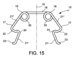
請求項1~6のいずれか1つに記載のアセンブリ(100)。 - 前記少なくとも1つのスプリング(15)は、実質的に逆「U」字型であり、前記少なくとも1つのスプリング(15)は、対称面(16)を画定する、および/または、
前記少なくとも1つのスプリング(15)は、2つの連結部またはスプリングアーム(17)と、ブリッジ部(18)とを含み、前記ブリッジ部(18)は、前記2つの連結部またはスプリングアーム(17)の間に介在する、および/または、
前記連結部またはスプリングアーム(17)は、前記2つのパッド(6)のそれぞれの耳部(12)に連結されるように構成される、および/または、
前記2つの連結部またはスプリングアーム(17)は、前記対称面(16)に関して対称である、および/または、
前記スプリング(15)は、前記連結部またはスプリングアーム(17)の相対的な移動によって弾性変形可能であり、前記連結部またはスプリングアーム(17)は、それぞれの前記パッド(6)によって、前記ブリッジ部(18)に対して移動可能である、および/または、
前記2つの連結部またはスプリングアーム(17)のそれぞれは、第1のコネクタ(19)によって前記ブリッジ部(18)に接続されており、前記第1のコネクタ(19)は、円周のループまたは円弧として形成される、および/または、
前記第1のコネクタ(19)は、螺旋状である、および/または、
前記第1のコネクタ(19)は、少なくとも360度の角度を形成する少なくとも1つの第1の接続ループ(35)を備える螺旋状である、および/または、
前記スプリング(15)の前記連結部またはスプリングアーム(17)のそれぞれは、実質的に「Z」字型であり、前記連結部またはスプリングアーム(17)のそれぞれは、
-第1の斜部または第1の傾斜部(21’)と、
-第2の斜部または第2の傾斜部(21’’)と、
-戻り部(22)と、
を含む、および/または、
前記第1の傾斜部(21’)および第2の傾斜部(21’’)は、互いに実質的に平行であり、前記戻り部(22)は、前記第1の傾斜部(21’)と前記第2の傾斜部(21’’)との間に介在しており、前記戻り部は、前記第1の傾斜部(21’)および前記第2の傾斜部(21’’)に対して実質的に横向きである、
請求項1~7のいずれか1つに記載のアセンブリ(100)。 - 前記戻り部(22)は、前記耳部(12)のそれぞれの連結シート(13)の上に横たわるように構成されている、および/または、
前記連結部またはスプリングアーム(17)のそれぞれの前記第1の傾斜部(21’)は、その第1の端部において、第2のコネクタ(24)によって前記戻り部(22)に接続されており、前記第2のコネクタ(24)は、円周のループまたは円弧として形成されている、および/または、
前記第1の傾斜部(21’)の第2の端部は、フック形状の端部23を形成している、および/または
前記スプリング(15)は、作動位置において、前記連結部またはスプリングアーム(17)が前記パッド(6)と前記ブレーキディスク(3)との間に介在するように構成されている、および/または、
前記スプリング(15)は、ワイヤータイプである、および/または、
前記スプリング(15)は、リーフタイプである、および/または、
前記スプリング(15)は、互いに実質的に平行であり、かつ前記スプリング(15)の前記対称面(16)に実質的に平行である軸に関してのみ曲率を示すように成形された単一のストリップ状の鋼片で形成されている、
請求項8に記載のアセンブリ(100)。 - 少なくとも2つのパッド(6)および少なくとも1つのスプリング(15)を含む、請求項1~9のいずれか1つに記載のアセンブリ(100)を含むキャリパ(2)。
- 前記少なくとも1つのスプリング(15)は、前記キャリパ(2)に対する前記パッドの動きによる振動および騒音の発生を低減するように、前記パッド(6)をポケット(9)内で弾性的に停止させるというさらなる機能を果たすように構成されている、
請求項10に記載のキャリパ(2)。 - 前記キャリパ(2)は、「フローティング」タイプである、
請求項10または11に記載のキャリパ(2)。 - 少なくとも2つのパッド(6)および少なくとも1つのスプリング(15)を含む、請求項1~9のいずれか1つに記載のアセンブリ(100)と、
請求項10~12のいずれか1つに記載のキャリパ(2)と、
ブレーキディスク(3)を含む、
ディスクブレーキ(1)。 - 対向する2つのブレーキパッド(6)をスプリング(15)を使って常時弾性的にバイアスする方法であって、
請求項1~9の少なくとも1つに記載のアセンブリ(100)を提供するステップと、
少なくとも1つの前記スプリング(15)を前記パッド(6)に直接排他的に接続するステップと、
前記パッド(6)の摩擦材料(8)の摩耗中に、前記スプリング(15)をスプリング連結プレート部(37)に関してヒンジのように回動させるステップと、
制動動作が終わったとき、前記スプリング(15)を前記内側下エッジ(25)および前記上側スプリング連結プレート部エッジ(29)に対してスライドして、前記パッド(6)をブレーキから離すように実質的に全体に前記軸方向(A-A)に弾性バイアスを適用するステップと、
を含む方法。
Applications Claiming Priority (5)
| Application Number | Priority Date | Filing Date | Title |
|---|---|---|---|
| IT102018000020527 | 2018-12-20 | ||
| IT102018000020527A IT201800020527A1 (it) | 2018-12-20 | 2018-12-20 | Assieme di pastiglie-molla per freno a disco |
| IT102019000023940A IT201900023940A1 (it) | 2019-12-13 | 2019-12-13 | Assieme di almeno due pastiglie freno e almeno una molla |
| IT102019000023940 | 2019-12-13 | ||
| PCT/IB2019/061201 WO2020129012A1 (en) | 2018-12-20 | 2019-12-20 | Assembly of at least two brake pads and at least one spring |
Publications (2)
| Publication Number | Publication Date |
|---|---|
| JP2022515189A JP2022515189A (ja) | 2022-02-17 |
| JP7589151B2 true JP7589151B2 (ja) | 2024-11-25 |
Family
ID=69165448
Family Applications (1)
| Application Number | Title | Priority Date | Filing Date |
|---|---|---|---|
| JP2021536008A Active JP7589151B2 (ja) | 2018-12-20 | 2019-12-20 | 少なくとも2つのブレーキパッドおよび少なくとも1つのスプリングのアセンブリ |
Country Status (5)
| Country | Link |
|---|---|
| US (1) | US11852207B2 (ja) |
| EP (1) | EP3899306B1 (ja) |
| JP (1) | JP7589151B2 (ja) |
| CN (1) | CN113195920B (ja) |
| WO (1) | WO2020129012A1 (ja) |
Families Citing this family (4)
| Publication number | Priority date | Publication date | Assignee | Title |
|---|---|---|---|---|
| IT202100000743A1 (it) | 2021-01-18 | 2022-07-18 | Brembo Spa | Molla a nastro ed assieme di molla a nastro e pastiglia freno |
| IT202100000749A1 (it) | 2021-01-18 | 2022-07-18 | Brembo Spa | Molla a nastro ed assieme di molla a nastro e pastiglia freno |
| CN217440641U (zh) * | 2022-04-29 | 2022-09-16 | 蔚来汽车科技(安徽)有限公司 | 制动钳组件、制动器及车辆 |
| IT202300004659A1 (it) * | 2023-03-13 | 2024-09-13 | Brembo Spa | Molla di riposizionamento, assieme di pinza freno e molla di riposizionamento |
Citations (2)
| Publication number | Priority date | Publication date | Assignee | Title |
|---|---|---|---|---|
| JP2004176868A (ja) | 2002-11-28 | 2004-06-24 | Advics:Kk | ディスクブレーキ |
| JP2014522469A (ja) | 2011-06-13 | 2014-09-04 | ヌーキャップ ユーエス インク | 摩擦パッドスプレッダ、該摩擦パッドスプレッダを備えるアセンブリ、及び該摩擦パッドスプレッダの取り付け方法 |
Family Cites Families (18)
| Publication number | Priority date | Publication date | Assignee | Title |
|---|---|---|---|---|
| JPS624744Y2 (ja) | 1980-06-23 | 1987-02-03 | ||
| JP2002039236A (ja) * | 2000-07-25 | 2002-02-06 | Aisin Seiki Co Ltd | フローティングキャリパ型のディスクブレーキ |
| EP1336055A4 (en) * | 2000-10-18 | 2005-01-12 | Akebono Corp North America | RETRACTION AND RETAINER SPRING IN A COMPASS DISK BRAKE ASSEMBLY |
| US6719105B1 (en) | 2002-06-26 | 2004-04-13 | Kelsey-Hayes Company | Pad retraction spring for disc brake assembly |
| US7644809B2 (en) * | 2003-07-31 | 2010-01-12 | Freni Brembo S.P.A. | Spring member for disc-brake calipers and disc-brake caliper |
| US7784591B2 (en) * | 2006-03-15 | 2010-08-31 | Kelsey-Hayes Company | Defined brake pad abutment |
| JP2012072830A (ja) | 2010-09-28 | 2012-04-12 | Akebono Brake Ind Co Ltd | ディスクブレーキのパッド戻し機構 |
| US8376092B2 (en) | 2011-02-10 | 2013-02-19 | Akebono Brake Corp. | Pad retraction device |
| JP2012189188A (ja) * | 2011-03-14 | 2012-10-04 | Akebono Brake Ind Co Ltd | ディスクブレーキ用パッドの戻し装置 |
| US9062729B2 (en) * | 2012-11-06 | 2015-06-23 | Akebono Brake Corporation | Brake pad coupler |
| CN106536961B (zh) * | 2014-05-27 | 2019-01-29 | 福乐尼·乐姆宝公开有限公司 | 盘式制动器的卡钳的弹簧 |
| DE112015003544T5 (de) * | 2014-08-01 | 2017-06-01 | Freni Brembo S.P.A. | Belaganordnung einer Scheibenbremse und Druckvorrichtung |
| US9670977B2 (en) * | 2014-09-11 | 2017-06-06 | Akebono Brake Industry Co., Ltd. | High-low pad retraction spring |
| EP3250839B1 (en) * | 2015-01-30 | 2022-04-13 | BREMBO S.p.A. | Pad and spring assembly for a disc brake caliper |
| US10400838B2 (en) | 2016-07-21 | 2019-09-03 | Preferred Tool & Die, Inc. | Caliper hardware providing separation between pad and rotor |
| IT201600130800A1 (it) * | 2016-12-23 | 2018-06-23 | Freni Brembo Spa | Dispositivo a molla per freno a disco, assieme di pastiglia e molla e pinza freno |
| DE102017222639A1 (de) | 2017-01-31 | 2018-08-02 | Continental Teves Ag & Co. Ohg | Festsattelkraftfahrzeugteilbelagscheibenbremse mit einer Stahlblechbügellüftspielfeder |
| DE102017204696A1 (de) | 2017-03-21 | 2018-09-27 | Continental Teves Ag & Co. Ohg | Einstückige Rückstellfeder für Kraftfahrzeugscheibenbremsbeläge |
-
2019
- 2019-12-20 US US17/416,062 patent/US11852207B2/en active Active
- 2019-12-20 CN CN201980084775.2A patent/CN113195920B/zh active Active
- 2019-12-20 WO PCT/IB2019/061201 patent/WO2020129012A1/en not_active Ceased
- 2019-12-20 JP JP2021536008A patent/JP7589151B2/ja active Active
- 2019-12-20 EP EP19836587.6A patent/EP3899306B1/en active Active
Patent Citations (2)
| Publication number | Priority date | Publication date | Assignee | Title |
|---|---|---|---|---|
| JP2004176868A (ja) | 2002-11-28 | 2004-06-24 | Advics:Kk | ディスクブレーキ |
| JP2014522469A (ja) | 2011-06-13 | 2014-09-04 | ヌーキャップ ユーエス インク | 摩擦パッドスプレッダ、該摩擦パッドスプレッダを備えるアセンブリ、及び該摩擦パッドスプレッダの取り付け方法 |
Also Published As
| Publication number | Publication date |
|---|---|
| CN113195920A (zh) | 2021-07-30 |
| WO2020129012A1 (en) | 2020-06-25 |
| JP2022515189A (ja) | 2022-02-17 |
| CN113195920B (zh) | 2023-08-11 |
| EP3899306A1 (en) | 2021-10-27 |
| US20220056970A1 (en) | 2022-02-24 |
| US11852207B2 (en) | 2023-12-26 |
| EP3899306B1 (en) | 2024-06-26 |
Similar Documents
| Publication | Publication Date | Title |
|---|---|---|
| JP7589151B2 (ja) | 少なくとも2つのブレーキパッドおよび少なくとも1つのスプリングのアセンブリ | |
| US5875873A (en) | Air disc brake anti-rattle design | |
| CN108138877B (zh) | 磨损优化的片设计 | |
| CN106715945B (zh) | 盘式制动器 | |
| EP1443234B1 (en) | A disc brake assembly | |
| US7316301B2 (en) | Brake caliper | |
| CN118128847A (zh) | 用于滑动卡钳式的机动车辆局部加衬的盘式制动器的摩擦衬片组件 | |
| US6223867B1 (en) | Disk brake | |
| US12234871B2 (en) | Brake pad retainer system, brake pad, and vehicle | |
| US20180347648A1 (en) | Brake pad | |
| EP1211433A2 (en) | Method and apparatus for mounting a brake disc | |
| EP1798438A1 (en) | Brake disc mounting with tangential disc springs | |
| JPS5917292B2 (ja) | 摺動キヤリパデイスクブレ−キ | |
| US4480725A (en) | Spot type brake with floating caliper | |
| US5022502A (en) | Tee anchor for duo servo drum brakes | |
| CA2997351C (en) | Wear optimized pad design | |
| AU2018217707B2 (en) | Wear optimized pad design | |
| JPH022097Y2 (ja) | ||
| HK1250770B (zh) | 磨損優化的片設計 | |
| JPH11344057A (ja) | ディスクブレーキおよびディスクブレーキ用摩擦パッド | |
| JP2008002643A (ja) | ディスクブレーキ用アンチラトルスプリング及びディスクブレーキ |
Legal Events
| Date | Code | Title | Description |
|---|---|---|---|
| A621 | Written request for application examination |
Free format text: JAPANESE INTERMEDIATE CODE: A621 Effective date: 20221202 |
|
| A977 | Report on retrieval |
Free format text: JAPANESE INTERMEDIATE CODE: A971007 Effective date: 20231221 |
|
| A131 | Notification of reasons for refusal |
Free format text: JAPANESE INTERMEDIATE CODE: A131 Effective date: 20240123 |
|
| A601 | Written request for extension of time |
Free format text: JAPANESE INTERMEDIATE CODE: A601 Effective date: 20240422 |
|
| A601 | Written request for extension of time |
Free format text: JAPANESE INTERMEDIATE CODE: A601 Effective date: 20240620 |
|
| A521 | Request for written amendment filed |
Free format text: JAPANESE INTERMEDIATE CODE: A523 Effective date: 20240722 |
|
| TRDD | Decision of grant or rejection written | ||
| A01 | Written decision to grant a patent or to grant a registration (utility model) |
Free format text: JAPANESE INTERMEDIATE CODE: A01 Effective date: 20241015 |
|
| A61 | First payment of annual fees (during grant procedure) |
Free format text: JAPANESE INTERMEDIATE CODE: A61 Effective date: 20241113 |
|
| R150 | Certificate of patent or registration of utility model |
Ref document number: 7589151 Country of ref document: JP Free format text: JAPANESE INTERMEDIATE CODE: R150 |