JP7378086B2 - 鋼製箱桁の設計方法および鋼製箱桁 - Google Patents
鋼製箱桁の設計方法および鋼製箱桁 Download PDFInfo
- Publication number
- JP7378086B2 JP7378086B2 JP2020133201A JP2020133201A JP7378086B2 JP 7378086 B2 JP7378086 B2 JP 7378086B2 JP 2020133201 A JP2020133201 A JP 2020133201A JP 2020133201 A JP2020133201 A JP 2020133201A JP 7378086 B2 JP7378086 B2 JP 7378086B2
- Authority
- JP
- Japan
- Prior art keywords
- box girder
- steel box
- belly plate
- steel
- plate
- Prior art date
- Legal status (The legal status is an assumption and is not a legal conclusion. Google has not performed a legal analysis and makes no representation as to the accuracy of the status listed.)
- Active
Links
- 229910000831 Steel Inorganic materials 0.000 title claims description 155
- 239000010959 steel Substances 0.000 title claims description 155
- 238000000034 method Methods 0.000 title claims description 24
- 210000001015 abdomen Anatomy 0.000 claims description 155
- 239000003351 stiffener Substances 0.000 claims description 72
- 238000005452 bending Methods 0.000 claims description 33
- 230000003187 abdominal effect Effects 0.000 claims description 28
- 230000033228 biological regulation Effects 0.000 claims description 16
- 230000006835 compression Effects 0.000 claims description 13
- 238000007906 compression Methods 0.000 claims description 13
- 230000007423 decrease Effects 0.000 description 11
- 239000002436 steel type Substances 0.000 description 6
- 238000003466 welding Methods 0.000 description 6
- 230000003247 decreasing effect Effects 0.000 description 4
- 238000006073 displacement reaction Methods 0.000 description 4
- 239000002131 composite material Substances 0.000 description 3
- 230000000694 effects Effects 0.000 description 3
- 238000010586 diagram Methods 0.000 description 2
- 239000000463 material Substances 0.000 description 2
- 239000007787 solid Substances 0.000 description 2
- 238000012790 confirmation Methods 0.000 description 1
- 238000004519 manufacturing process Methods 0.000 description 1
- 238000010008 shearing Methods 0.000 description 1
- 239000013589 supplement Substances 0.000 description 1
Images


Landscapes
- Bridges Or Land Bridges (AREA)
Description
(1-1)構成
図1は、本発明の第1実施形態に係る鋼製箱桁10を示す斜視図であり、図2は、図1のII-II線断面図(橋軸方向と直交する鉛直面で切断した鉛直断面図)である。図1では、鋼製箱桁10の内部の構造をわかりやすく示すために、上側フランジ14および手前側の内側腹板16の大部分の記載を省略している。
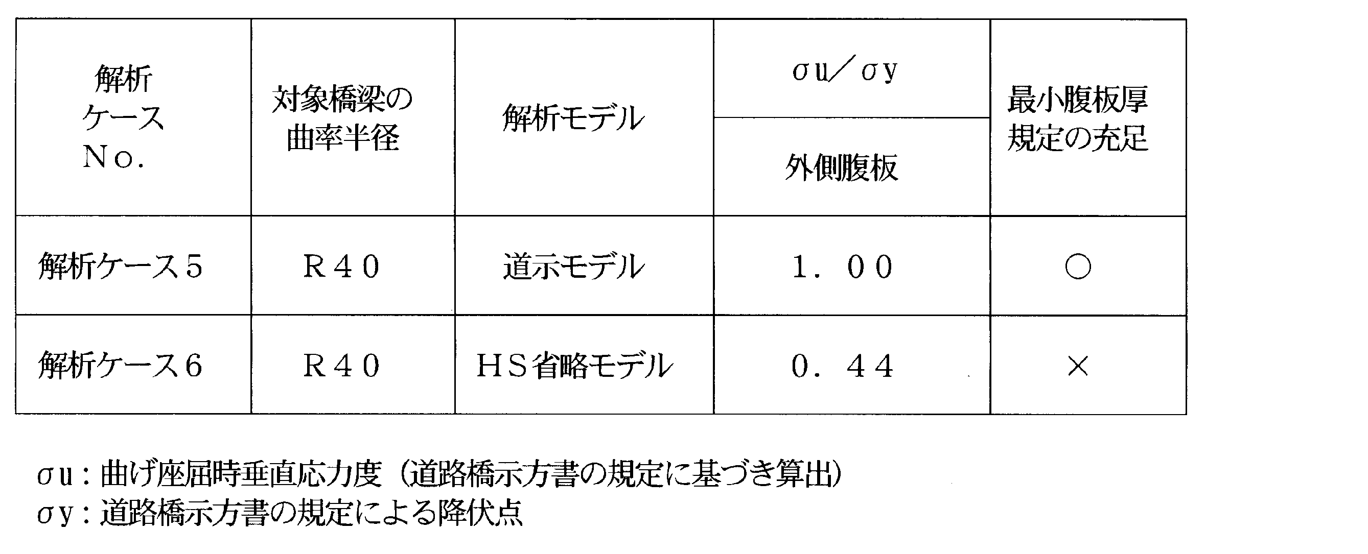
本第1実施形態に係る鋼製箱桁10の作用効果を証明するFEM解析の前提条件および結果について説明する。以下、道路橋示方書に基づいて設計された解析モデルを道示モデルと記すことがあり、腹板に取り付ける水平補剛材のうち、所定の領域の水平補剛材を省略した解析モデルをHS省略モデルと記すことがある(第2実施形態におけるFEM解析の説明でも同様に記載する。)。


(2-1)構成
図10は、本発明の第2実施形態に係る鋼製箱桁50の支間中央部の鉛直断面図(橋軸方向と直交する鉛直面で切断した支間中央部の鉛直断面図)である。
本第2実施形態に係る鋼製箱桁50の作用効果を証明するFEM解析の前提条件および結果について説明する。
第1実施形態に係る鋼製箱桁10および第2実施形態に係る鋼製箱桁50は、曲率半径40mの橋梁上部工の一部を形成している鋼製曲線箱桁であるものとして説明したが、本発明に係る鋼製箱桁が曲率半径40mの鋼製曲線箱桁に限定されるわけではなく、本発明に係る鋼製箱桁は、それ以外の曲率半径でもよく、また、直線型の鋼製箱桁であってもよい。
12、52…下側フランジ
12A、52A…下側縦リブ
14、54…上側フランジ
14A、54A…上側縦リブ
16、16A、16B、56…内側腹板
18、18A、18B、58、58A、58B…外側腹板
20、60…垂直補剛材
22、62…ダイアフラム
22A…支点上補剛材
24、64…横リブ
30、70…対象部位
32、72…道示モデル
32X、32Y、36X、36Y、72X、72Y…図心位置
34、34A、74…水平補剛材
36…HS省略モデル
80…ソールプレート
100…鋼3径間連続合成箱桁橋
Claims (6)
- 上側フランジおよび下側フランジと、橋軸方向に沿って配置されていて橋軸直角方向に対向する第1の腹板および第2の腹板で構成された閉断面の箱型構造を有する鋼製箱桁を設計する方法であって、
前記鋼製箱桁が橋梁の上部工として架設された状態において、該鋼製箱桁に、前死荷重である鋼重に荷重倍率αを乗じた荷重を、前記荷重倍率αを増大させつつ加えていったとき、前記第1の腹板および前記第2の腹板に曲げ座屈またはせん断座屈が生じた後、前記上側フランジ及び前記下側フランジの部位のうち、圧縮力が生じている部位である圧縮フランジに全体座屈が生じて前記鋼製箱桁が終局状態に達することをFEM解析で確認する工程を有することを特徴とする鋼製箱桁の設計方法。 - 前記第1の腹板および前記第2の腹板のうちの少なくとも一方の厚さが、道路橋示方書の規定に従って算出される最小腹板厚よりも小さいことを特徴とする請求項1に記載の鋼製箱桁の設計方法。
- 前記鋼製箱桁が、曲線箱桁橋の上部工の少なくとも一部として用いられることを特徴とする請求項1または2に記載の鋼製箱桁の設計方法。
- 上側フランジおよび下側フランジと、橋軸方向に沿って配置されていて橋軸直角方向に対向する第1の腹板および第2の腹板で構成された閉断面の箱型構造を有する鋼製箱桁であって、
前記鋼製箱桁が橋梁の上部工として架設された状態において、該鋼製箱桁にFEM解析を行って、該鋼製箱桁に、前死荷重である鋼重に荷重倍率αを乗じた荷重を、前記荷重倍率αを増大させつつ加えていったとき、前記第1の腹板および前記第2の腹板に曲げ座屈またはせん断座屈が生じた後、前記上側フランジ及び前記下側フランジの部位のうち、圧縮力が生じている部位である圧縮フランジに全体座屈が生じて終局状態に達していることを確認できたものであって、かつ、前記第1の腹板および前記第2の腹板には水平補剛材が取り付けられていないことを特徴とする鋼製箱桁。 - 前記第1の腹板および前記第2の腹板のうちの少なくとも一方の厚さが、道路橋示方書の規定に従って算出される最小腹板厚よりも小さいことを特徴とする請求項4に記載の鋼製箱桁。
- 曲線箱桁橋の上部工の少なくとも一部として用いられることを特徴とする請求項4または5に記載の鋼製箱桁。
Priority Applications (1)
| Application Number | Priority Date | Filing Date | Title |
|---|---|---|---|
| JP2020133201A JP7378086B2 (ja) | 2020-08-05 | 2020-08-05 | 鋼製箱桁の設計方法および鋼製箱桁 |
Applications Claiming Priority (1)
| Application Number | Priority Date | Filing Date | Title |
|---|---|---|---|
| JP2020133201A JP7378086B2 (ja) | 2020-08-05 | 2020-08-05 | 鋼製箱桁の設計方法および鋼製箱桁 |
Publications (2)
| Publication Number | Publication Date |
|---|---|
| JP2022029742A JP2022029742A (ja) | 2022-02-18 |
| JP7378086B2 true JP7378086B2 (ja) | 2023-11-13 |
Family
ID=80325008
Family Applications (1)
| Application Number | Title | Priority Date | Filing Date |
|---|---|---|---|
| JP2020133201A Active JP7378086B2 (ja) | 2020-08-05 | 2020-08-05 | 鋼製箱桁の設計方法および鋼製箱桁 |
Country Status (1)
| Country | Link |
|---|---|
| JP (1) | JP7378086B2 (ja) |
Citations (4)
| Publication number | Priority date | Publication date | Assignee | Title |
|---|---|---|---|---|
| JP2006132308A (ja) | 2004-10-06 | 2006-05-25 | Nippon Steel Corp | 板状部材の補剛構造及び当該補剛構造を用いた柱構造 |
| JP2011080211A (ja) | 2009-10-05 | 2011-04-21 | Hanshin Kosoku Doro Kanri Gijutsu Center | 点検対象部材の決定方法 |
| JP2018172927A (ja) | 2017-03-31 | 2018-11-08 | 株式会社Ihi | 柱構造体 |
| JP2019194428A (ja) | 2018-05-01 | 2019-11-07 | Jfeスチール株式会社 | H形鋼製梁 |
-
2020
- 2020-08-05 JP JP2020133201A patent/JP7378086B2/ja active Active
Patent Citations (4)
| Publication number | Priority date | Publication date | Assignee | Title |
|---|---|---|---|---|
| JP2006132308A (ja) | 2004-10-06 | 2006-05-25 | Nippon Steel Corp | 板状部材の補剛構造及び当該補剛構造を用いた柱構造 |
| JP2011080211A (ja) | 2009-10-05 | 2011-04-21 | Hanshin Kosoku Doro Kanri Gijutsu Center | 点検対象部材の決定方法 |
| JP2018172927A (ja) | 2017-03-31 | 2018-11-08 | 株式会社Ihi | 柱構造体 |
| JP2019194428A (ja) | 2018-05-01 | 2019-11-07 | Jfeスチール株式会社 | H形鋼製梁 |
Also Published As
| Publication number | Publication date |
|---|---|
| JP2022029742A (ja) | 2022-02-18 |
Similar Documents
| Publication | Publication Date | Title |
|---|---|---|
| Sabbagh et al. | Ductile moment-resisting frames using cold-formed steel sections: An analytical investigation | |
| JP2018131882A (ja) | 基礎構造 | |
| JP6919672B2 (ja) | H形鋼製梁 | |
| Itani et al. | Horizontally curved bridges | |
| KR102341335B1 (ko) | 교량용 거더 | |
| JP4819605B2 (ja) | 端部と中央部とで強度の異なる緊張材を用いたプレキャストプレストレストコンクリート梁 | |
| JP7378086B2 (ja) | 鋼製箱桁の設計方法および鋼製箱桁 | |
| JP2875106B2 (ja) | 構造部材の補強構造及び補強金具 | |
| JP6956466B2 (ja) | 鉄骨梁および柱梁接合構造 | |
| US8615969B2 (en) | Reinforcement structure of rectangular flat metal plate | |
| JP4414833B2 (ja) | 波形鋼板を用いた耐震壁 | |
| JP4618805B2 (ja) | 複層金属平板の補強構造 | |
| JP2002266317A (ja) | 橋梁用連続桁 | |
| JP6128058B2 (ja) | 梁端部の接合構造 | |
| JPH1181240A (ja) | 連続桁橋の桁構造 | |
| JP7234084B2 (ja) | 床スラブ付き鉄骨梁およびその補強方法 | |
| JP7453937B2 (ja) | 鉄骨梁 | |
| JP6936033B2 (ja) | 床構造の開口幅設定方法および床構造 | |
| JP6513754B2 (ja) | 鉄筋コンクリート壁柱の補強構造 | |
| JP7143781B2 (ja) | 梁端接合部 | |
| JP7314030B2 (ja) | 開口を有する床スラブ付き鉄骨梁およびその補強方法 | |
| JP2005042423A (ja) | 金属平板のせん断補強構造 | |
| JP7262518B2 (ja) | 間柱型鋼材ダンパー | |
| WO2010116660A1 (ja) | 異方性補強金属板 | |
| JP7351271B2 (ja) | 鉄骨梁、柱梁接合構造およびこれを有する構造物 |
Legal Events
| Date | Code | Title | Description |
|---|---|---|---|
| A80 | Written request to apply exceptions to lack of novelty of invention |
Free format text: JAPANESE INTERMEDIATE CODE: A80 Effective date: 20200903 |
|
| A621 | Written request for application examination |
Free format text: JAPANESE INTERMEDIATE CODE: A621 Effective date: 20230131 |
|
| TRDD | Decision of grant or rejection written | ||
| A977 | Report on retrieval |
Free format text: JAPANESE INTERMEDIATE CODE: A971007 Effective date: 20230922 |
|
| A01 | Written decision to grant a patent or to grant a registration (utility model) |
Free format text: JAPANESE INTERMEDIATE CODE: A01 Effective date: 20230926 |
|
| A61 | First payment of annual fees (during grant procedure) |
Free format text: JAPANESE INTERMEDIATE CODE: A61 Effective date: 20231023 |
|
| R150 | Certificate of patent or registration of utility model |
Ref document number: 7378086 Country of ref document: JP Free format text: JAPANESE INTERMEDIATE CODE: R150 |