JP7169171B2 - 半導体装置及び距離計測装置 - Google Patents
半導体装置及び距離計測装置 Download PDFInfo
- Publication number
- JP7169171B2 JP7169171B2 JP2018216715A JP2018216715A JP7169171B2 JP 7169171 B2 JP7169171 B2 JP 7169171B2 JP 2018216715 A JP2018216715 A JP 2018216715A JP 2018216715 A JP2018216715 A JP 2018216715A JP 7169171 B2 JP7169171 B2 JP 7169171B2
- Authority
- JP
- Japan
- Prior art keywords
- signal
- phase
- input signal
- digital signal
- semiconductor device
- Prior art date
- Legal status (The legal status is an assumption and is not a legal conclusion. Google has not performed a legal analysis and makes no representation as to the accuracy of the status listed.)
- Active
Links
Images


Classifications
-
- G—PHYSICS
- G01—MEASURING; TESTING
- G01S—RADIO DIRECTION-FINDING; RADIO NAVIGATION; DETERMINING DISTANCE OR VELOCITY BY USE OF RADIO WAVES; LOCATING OR PRESENCE-DETECTING BY USE OF THE REFLECTION OR RERADIATION OF RADIO WAVES; ANALOGOUS ARRANGEMENTS USING OTHER WAVES
- G01S7/00—Details of systems according to groups G01S13/00, G01S15/00, G01S17/00
- G01S7/48—Details of systems according to groups G01S13/00, G01S15/00, G01S17/00 of systems according to group G01S17/00
- G01S7/483—Details of pulse systems
- G01S7/486—Receivers
- G01S7/4861—Circuits for detection, sampling, integration or read-out
-
- G—PHYSICS
- G01—MEASURING; TESTING
- G01S—RADIO DIRECTION-FINDING; RADIO NAVIGATION; DETERMINING DISTANCE OR VELOCITY BY USE OF RADIO WAVES; LOCATING OR PRESENCE-DETECTING BY USE OF THE REFLECTION OR RERADIATION OF RADIO WAVES; ANALOGOUS ARRANGEMENTS USING OTHER WAVES
- G01S17/00—Systems using the reflection or reradiation of electromagnetic waves other than radio waves, e.g. lidar systems
- G01S17/02—Systems using the reflection of electromagnetic waves other than radio waves
- G01S17/06—Systems determining position data of a target
- G01S17/08—Systems determining position data of a target for measuring distance only
- G01S17/10—Systems determining position data of a target for measuring distance only using transmission of interrupted, pulse-modulated waves
- G01S17/26—Systems determining position data of a target for measuring distance only using transmission of interrupted, pulse-modulated waves wherein the transmitted pulses use a frequency-modulated or phase-modulated carrier wave, e.g. for pulse compression of received signals
-
- G—PHYSICS
- G01—MEASURING; TESTING
- G01S—RADIO DIRECTION-FINDING; RADIO NAVIGATION; DETERMINING DISTANCE OR VELOCITY BY USE OF RADIO WAVES; LOCATING OR PRESENCE-DETECTING BY USE OF THE REFLECTION OR RERADIATION OF RADIO WAVES; ANALOGOUS ARRANGEMENTS USING OTHER WAVES
- G01S17/00—Systems using the reflection or reradiation of electromagnetic waves other than radio waves, e.g. lidar systems
- G01S17/02—Systems using the reflection of electromagnetic waves other than radio waves
- G01S17/06—Systems determining position data of a target
- G01S17/08—Systems determining position data of a target for measuring distance only
- G01S17/10—Systems determining position data of a target for measuring distance only using transmission of interrupted, pulse-modulated waves
- G01S17/14—Systems determining position data of a target for measuring distance only using transmission of interrupted, pulse-modulated waves wherein a voltage or current pulse is initiated and terminated in accordance with the pulse transmission and echo reception respectively, e.g. using counters
-
- G—PHYSICS
- G01—MEASURING; TESTING
- G01S—RADIO DIRECTION-FINDING; RADIO NAVIGATION; DETERMINING DISTANCE OR VELOCITY BY USE OF RADIO WAVES; LOCATING OR PRESENCE-DETECTING BY USE OF THE REFLECTION OR RERADIATION OF RADIO WAVES; ANALOGOUS ARRANGEMENTS USING OTHER WAVES
- G01S7/00—Details of systems according to groups G01S13/00, G01S15/00, G01S17/00
- G01S7/48—Details of systems according to groups G01S13/00, G01S15/00, G01S17/00 of systems according to group G01S17/00
- G01S7/483—Details of pulse systems
- G01S7/486—Receivers
- G01S7/4865—Time delay measurement, e.g. time-of-flight measurement, time of arrival measurement or determining the exact position of a peak
-
- H—ELECTRICITY
- H03—ELECTRONIC CIRCUITRY
- H03L—AUTOMATIC CONTROL, STARTING, SYNCHRONISATION OR STABILISATION OF GENERATORS OF ELECTRONIC OSCILLATIONS OR PULSES
- H03L7/00—Automatic control of frequency or phase; Synchronisation
- H03L7/06—Automatic control of frequency or phase; Synchronisation using a reference signal applied to a frequency- or phase-locked loop
- H03L7/08—Details of the phase-locked loop
- H03L7/081—Details of the phase-locked loop provided with an additional controlled phase shifter
- H03L7/0812—Details of the phase-locked loop provided with an additional controlled phase shifter and where no voltage or current controlled oscillator is used
- H03L7/0818—Details of the phase-locked loop provided with an additional controlled phase shifter and where no voltage or current controlled oscillator is used the controlled phase shifter comprising coarse and fine delay or phase-shifting means
-
- H—ELECTRICITY
- H03—ELECTRONIC CIRCUITRY
- H03L—AUTOMATIC CONTROL, STARTING, SYNCHRONISATION OR STABILISATION OF GENERATORS OF ELECTRONIC OSCILLATIONS OR PULSES
- H03L7/00—Automatic control of frequency or phase; Synchronisation
- H03L7/06—Automatic control of frequency or phase; Synchronisation using a reference signal applied to a frequency- or phase-locked loop
- H03L7/08—Details of the phase-locked loop
- H03L7/099—Details of the phase-locked loop concerning mainly the controlled oscillator of the loop
- H03L7/0991—Details of the phase-locked loop concerning mainly the controlled oscillator of the loop the oscillator being a digital oscillator, e.g. composed of a fixed oscillator followed by a variable frequency divider
- H03L7/0992—Details of the phase-locked loop concerning mainly the controlled oscillator of the loop the oscillator being a digital oscillator, e.g. composed of a fixed oscillator followed by a variable frequency divider comprising a counter or a frequency divider
-
- H—ELECTRICITY
- H03—ELECTRONIC CIRCUITRY
- H03L—AUTOMATIC CONTROL, STARTING, SYNCHRONISATION OR STABILISATION OF GENERATORS OF ELECTRONIC OSCILLATIONS OR PULSES
- H03L7/00—Automatic control of frequency or phase; Synchronisation
- H03L7/06—Automatic control of frequency or phase; Synchronisation using a reference signal applied to a frequency- or phase-locked loop
- H03L7/16—Indirect frequency synthesis, i.e. generating a desired one of a number of predetermined frequencies using a frequency- or phase-locked loop
-
- H—ELECTRICITY
- H03—ELECTRONIC CIRCUITRY
- H03K—PULSE TECHNIQUE
- H03K5/00—Manipulating of pulses not covered by one of the other main groups of this subclass
- H03K5/13—Arrangements having a single output and transforming input signals into pulses delivered at desired time intervals
- H03K5/135—Arrangements having a single output and transforming input signals into pulses delivered at desired time intervals by the use of time reference signals, e.g. clock signals
Landscapes
- Physics & Mathematics (AREA)
- Engineering & Computer Science (AREA)
- Electromagnetism (AREA)
- Computer Networks & Wireless Communication (AREA)
- General Physics & Mathematics (AREA)
- Radar, Positioning & Navigation (AREA)
- Remote Sensing (AREA)
- Optical Radar Systems And Details Thereof (AREA)
- Measurement Of Optical Distance (AREA)
- Analogue/Digital Conversion (AREA)
- Manipulation Of Pulses (AREA)
Description
図1は第1の実施形態による半導体装置1の概略構成を示すブロック図である。図1の半導体装置1は、同一の半導体基板上に実装される回路構成を示している。図1の半導体装置1は、発振器2と、周期数計測器3と、第1演算器4と、第2演算器5とを備えている。本明細書では、第1演算器4と第2演算器5を総称して演算器10と呼ぶ。
第2の実施形態は、第1の実施形態による半導体装置1の構成をより具体化したものである。
f(t)=at2+bt+c …(1)
小数時間=f-1(DPT) …(2)
図12は第3の実施形態による半導体装置1を内蔵する距離計測装置20の概略構成を示すブロック図である。図12の距離計測装置20は、制御部21と、光源22と、光検出器23と、アナログフロントエンド(以下、AFE:Analog Front End)部24と、算出器25とを備えている。
図13は第4の実施形態による半導体装置1の概略構成を示すブロック図である。図13の半導体装置1は、図7の半導体装置1の構成に加えて、比較器6を備えている。比較器6は、第1入力信号に基づいて第2入力信号を生成する。より具体的には、比較器6は、第1入力信号の物理量を所定の基準量と比較することにより、第2入力信号を生成する。物理量が信号レベルの場合、比較器6は、第1入力信号の信号レベルが所定の基準レベルを超えた場合に、第2入力信号を遷移させてもよい。このように、比較器6は、トリガ信号である第2入力信号を生成するトリガ生成部として機能する。
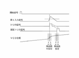
VCO2の発振信号は、第1入力信号に応じて周波数変調されている。よって、図14に示すように、1つのクロック周期内でも、発振信号の発振周波数が大きく変化することがありうる。特に、第1入力信号に含まれる反射光成分に対応する信号領域は、短い時間幅で信号振幅が急激に大きくなることがある。このような場合、VCO2の発振信号の発振周波数が急激に大きくなって、その後すぐに発振周波数が急激に小さくなり、発振周波数が不安定になる。
図18は第6の実施形態による半導体装置1の概略構成を示すブロック図である。図18の半導体装置1は、図7の半導体装置1の構成に加えて、DA変換器(DAC:Digital Analog Converter)27と、差分器28と、ループフィルタ29とを備えている。DAC27は、第1位相サンプラ11から出力された第1位相デジタル信号DPAを位相アナログ信号に変換する。差分器28は、第1入力信号とDAC27の出力信号と第1入力信号との差信号を出力する。ループフィルタ29は、この差信号を積分した信号を、第1入力信号の代わりにVCO2に入力する。ループフィルタ29は積分器として機能する。
Claims (12)
- 第1入力信号に応じて周波数が変調された発振信号を出力する発振器と、
前記発振信号の周期数を計測する周期数計測器と、
クロック信号の第1クロック周期に、前記周期数計測器で計測された第1周期数に基づいて、前記第1入力信号をデジタル変換した第1デジタル信号を出力する第1演算器と、
前記クロック信号の基準時点から第2入力信号が遷移するタイミングまでの期間に、前記周期数計測器で計測された第2周期数に基づいて、第2デジタル信号を出力する第2演算器と、を備える、半導体装置。 - 前記第1入力信号の物理量を基準値と比較することにより、前記第2入力信号を生成する比較器を備える、請求項1に記載の半導体装置。
- 前記第1デジタル信号及び前記第2デジタル信号に基づいて、光信号を出射してから前記光信号が物体で反射された反射光信号が受光されるまでの時間を計測し、前記時間に基づいて前記物体までの距離を算出する算出器を備える、請求項1又は2に記載の半導体装置。
- 第1入力信号に応じて周波数が変調された発振信号を出力する発振器と、
クロック信号のクロック周期に前記発振信号の位相をサンプリングした第1位相デジタル信号を出力する第1位相サンプラと、
第2入力信号が遷移したタイミングで前記発振信号の位相をサンプリングした第2位相デジタル信号を出力する第2位相サンプラと、
前記第2入力信号が遷移したタイミングで前記クロック信号の位相をサンプリングした第3位相デジタル信号を出力する第3位相サンプラと、
前記第1位相デジタル信号に基づいて、前記第1入力信号をデジタル変換した第1デジタル信号を生成する第1演算器と、
前記第1、第2及び第3位相デジタル信号に基づいて、前記第2入力信号が遷移するタイミングまでの期間に応じた第2デジタル信号を生成する第2演算器と、を備える、半導体装置。 - 前記第1演算器は、前記第1位相デジタル信号を時間微分することにより、前記第1デジタル信号を生成し、
前記第2演算器は、前記第2位相デジタル信号に近接した2以上の前記第1位相デジタル信号を内挿する処理と前記第3位相デジタル信号とに基づいて、前記第2デジタル信号を生成する、請求項4に記載の半導体装置。 - 前記第2演算器は、前記2以上の前記第1位相デジタル信号の多項式補間により前記第2位相デジタル信号に対応する小数時間を求めるとともに、前記第3位相デジタル信号に基づいて整数時間を求め、前記小数時間及び前記整数時間に基づいて前記第2デジタル信号を生成する、請求項5に記載の半導体装置。
- 前記第2入力信号を遅延させる遅延器を備え、
前記第2位相サンプラは、前記遅延器で遅延された第2入力信号が遷移したタイミングで前記第2位相デジタル信号を出力し、
前記第3位相サンプラは、前記遅延された第2入力信号が遷移したタイミングで前記第3位相デジタル信号を出力する、請求項4乃至6のいずれか一項に記載の半導体装置。 - 前記第1入力信号を遅延させる遅延器を備え、
前記発振器は、前記遅延器で遅延された第1入力信号の信号レベルに応じて周波数が変調された前記発振信号を出力する、請求項4乃至6のいずれか一項に記載の半導体装置。 - 前記第1入力信号の物理量を基準値と比較することにより、前記第2入力信号を生成する比較部を備える、請求項4乃至8のいずれか一項に記載の半導体装置。
- 前記物理量は、前記第1入力信号の電力、包絡線形状、周波数、積分値、又はパルス幅である、請求項9に記載の半導体装置。
- 前記第1位相デジタル信号を位相アナログ信号に変換するDA変換器と、
前記第1入力信号と前記位相アナログ信号との差信号を積分した信号を前記第1入力信号の代わりに前記発振器に入力するループフィルタと、を備える請求項4乃至10のいずれか一項に記載の半導体装置。 - 開始信号のタイミングに合わせて第1光信号を出射する光源と、
前記第1光信号が物体で反射された反射光信号を含む第2光信号を受光して、電気信号である前記第1入力信号に変換する光検出器と、
請求項1乃至11のいずれか一項に記載の半導体装置を有し、前記第1入力信号に基づいて、前記反射光信号の受光タイミングを表す前記第1デジタル信号及び前記第2デジタル信号を出力するフロントエンド部と、
前記第1デジタル信号及び前記第2デジタル信号に基づいて、前記開始信号のタイミングから前記第2入力信号が入力されるまでの時間を計測し、計測された時間に基づいて、前記物体までの距離を計測する距離演算部と、を備える、距離計測装置。
Priority Applications (5)
| Application Number | Priority Date | Filing Date | Title |
|---|---|---|---|
| JP2018216715A JP7169171B2 (ja) | 2018-11-19 | 2018-11-19 | 半導体装置及び距離計測装置 |
| DE102019212999.4A DE102019212999B4 (de) | 2018-11-19 | 2019-08-29 | Halbleiterschaltung und distanzmessvorrichtung |
| US16/562,817 US11573321B2 (en) | 2018-11-19 | 2019-09-06 | Semiconductor circuitry and distance measuring device |
| CN201910861327.0A CN111273308B (zh) | 2018-11-19 | 2019-09-12 | 半导体电路以及距离测量装置 |
| JP2022170980A JP7431924B2 (ja) | 2018-11-19 | 2022-10-25 | 半導体回路及び距離計測装置 |
Applications Claiming Priority (1)
| Application Number | Priority Date | Filing Date | Title |
|---|---|---|---|
| JP2018216715A JP7169171B2 (ja) | 2018-11-19 | 2018-11-19 | 半導体装置及び距離計測装置 |
Related Child Applications (1)
| Application Number | Title | Priority Date | Filing Date |
|---|---|---|---|
| JP2022170980A Division JP7431924B2 (ja) | 2018-11-19 | 2022-10-25 | 半導体回路及び距離計測装置 |
Publications (2)
| Publication Number | Publication Date |
|---|---|
| JP2020085537A JP2020085537A (ja) | 2020-06-04 |
| JP7169171B2 true JP7169171B2 (ja) | 2022-11-10 |
Family
ID=70470363
Family Applications (2)
| Application Number | Title | Priority Date | Filing Date |
|---|---|---|---|
| JP2018216715A Active JP7169171B2 (ja) | 2018-11-19 | 2018-11-19 | 半導体装置及び距離計測装置 |
| JP2022170980A Active JP7431924B2 (ja) | 2018-11-19 | 2022-10-25 | 半導体回路及び距離計測装置 |
Family Applications After (1)
| Application Number | Title | Priority Date | Filing Date |
|---|---|---|---|
| JP2022170980A Active JP7431924B2 (ja) | 2018-11-19 | 2022-10-25 | 半導体回路及び距離計測装置 |
Country Status (4)
| Country | Link |
|---|---|
| US (1) | US11573321B2 (ja) |
| JP (2) | JP7169171B2 (ja) |
| CN (1) | CN111273308B (ja) |
| DE (1) | DE102019212999B4 (ja) |
Families Citing this family (2)
| Publication number | Priority date | Publication date | Assignee | Title |
|---|---|---|---|---|
| JP7169171B2 (ja) * | 2018-11-19 | 2022-11-10 | 株式会社東芝 | 半導体装置及び距離計測装置 |
| JP7527946B2 (ja) | 2020-12-11 | 2024-08-05 | 株式会社東芝 | 発振回路、時間デジタル変換器、及び電子装置 |
Citations (3)
| Publication number | Priority date | Publication date | Assignee | Title |
|---|---|---|---|---|
| JP2000028721A (ja) | 1998-07-14 | 2000-01-28 | Minolta Co Ltd | 測距装置 |
| JP2003139857A (ja) | 2001-11-01 | 2003-05-14 | Nec Eng Ltd | レーザ測距装置 |
| JP2017063433A (ja) | 2010-01-15 | 2017-03-30 | 株式会社半導体エネルギー研究所 | 半導体装置 |
Family Cites Families (17)
| Publication number | Priority date | Publication date | Assignee | Title |
|---|---|---|---|---|
| JPH01170221A (ja) | 1987-12-25 | 1989-07-05 | Mitsubishi Electric Corp | アナログデイジタル変換装置 |
| JPH01208024A (ja) * | 1988-02-16 | 1989-08-22 | Nippon Telegr & Teleph Corp <Ntt> | 量子化器 |
| JPH0415593A (ja) * | 1990-05-09 | 1992-01-20 | Nikon Corp | 高分解能時間差計測装置 |
| JP2757600B2 (ja) | 1991-07-30 | 1998-05-25 | 株式会社デンソー | 時間a/d変換回路 |
| JP2002100967A (ja) * | 2000-03-17 | 2002-04-05 | Sony Corp | 電源電圧制御装置、半導体装置およびその駆動方法 |
| JP2005182872A (ja) * | 2003-12-17 | 2005-07-07 | Toshiba Corp | 不揮発性半導体記憶装置 |
| US8045670B2 (en) * | 2007-06-22 | 2011-10-25 | Texas Instruments Incorporated | Interpolative all-digital phase locked loop |
| JP4729054B2 (ja) * | 2008-01-28 | 2011-07-20 | 株式会社東芝 | 通信用半導体集積回路 |
| JP2012060603A (ja) * | 2010-09-13 | 2012-03-22 | Toshiba Corp | 半導体集積回路および無線通信装置 |
| EP2597483B8 (de) * | 2011-11-25 | 2017-06-07 | Safran Vectronix AG | Entfernungsmesser |
| US9632179B2 (en) * | 2012-07-04 | 2017-04-25 | Blackberry Limited | Estimating a baseline of a proximity sensor |
| JP6479155B2 (ja) * | 2015-02-19 | 2019-03-06 | 三菱電機株式会社 | Fm−cwレーダおよびfm−cw信号の生成方法 |
| CN105044678B (zh) * | 2015-06-26 | 2017-11-17 | 复旦大学 | 基于全数字锁相环架构的雷达应答/干扰一体无线通讯器 |
| US10191154B2 (en) * | 2016-02-11 | 2019-01-29 | Massachusetts Institute Of Technology | Methods and apparatus for time-of-flight imaging |
| CN106950539B (zh) * | 2017-03-03 | 2020-05-12 | 长沙理工大学 | 基于时差法的高精度反gps跟踪模块定位识别方法 |
| US10007001B1 (en) * | 2017-03-28 | 2018-06-26 | Luminar Technologies, Inc. | Active short-wave infrared four-dimensional camera |
| JP7169171B2 (ja) * | 2018-11-19 | 2022-11-10 | 株式会社東芝 | 半導体装置及び距離計測装置 |
-
2018
- 2018-11-19 JP JP2018216715A patent/JP7169171B2/ja active Active
-
2019
- 2019-08-29 DE DE102019212999.4A patent/DE102019212999B4/de active Active
- 2019-09-06 US US16/562,817 patent/US11573321B2/en active Active
- 2019-09-12 CN CN201910861327.0A patent/CN111273308B/zh active Active
-
2022
- 2022-10-25 JP JP2022170980A patent/JP7431924B2/ja active Active
Patent Citations (3)
| Publication number | Priority date | Publication date | Assignee | Title |
|---|---|---|---|---|
| JP2000028721A (ja) | 1998-07-14 | 2000-01-28 | Minolta Co Ltd | 測距装置 |
| JP2003139857A (ja) | 2001-11-01 | 2003-05-14 | Nec Eng Ltd | レーザ測距装置 |
| JP2017063433A (ja) | 2010-01-15 | 2017-03-30 | 株式会社半導体エネルギー研究所 | 半導体装置 |
Also Published As
| Publication number | Publication date |
|---|---|
| JP7431924B2 (ja) | 2024-02-15 |
| DE102019212999A1 (de) | 2020-05-20 |
| JP2022186902A (ja) | 2022-12-15 |
| US20200158872A1 (en) | 2020-05-21 |
| JP2020085537A (ja) | 2020-06-04 |
| US11573321B2 (en) | 2023-02-07 |
| CN111273308B (zh) | 2023-10-20 |
| CN111273308A (zh) | 2020-06-12 |
| DE102019212999B4 (de) | 2025-05-08 |
Similar Documents
| Publication | Publication Date | Title |
|---|---|---|
| CN112005128B (zh) | 飞行时间装置和用于飞行时间测量的方法 | |
| JP3935897B2 (ja) | 光波測距装置 | |
| KR102631502B1 (ko) | 아날로그-디지털 컨버터 | |
| JP7431924B2 (ja) | 半導体回路及び距離計測装置 | |
| KR100982103B1 (ko) | 시간-디지털 변환기, 시간-디지털 변환 방법 및 컴퓨터 판독가능한 저장 매체 | |
| US11079723B2 (en) | Apparatus and methods for automatic time measurements | |
| US8879048B2 (en) | Device and method for determining the distance to an object | |
| Keränen et al. | A wide range, 4.2 ps (rms) precision CMOS TDC with cyclic interpolators based on switched-frequency ring oscillators | |
| US10534322B2 (en) | Use of ring oscillators for multi-stop time measurements | |
| US20240142584A1 (en) | Lidar time-of-flight signal processing | |
| US10725433B2 (en) | Time-to-digital conversion circuitry | |
| CN110622038A (zh) | 光传感器、电子设备、运算装置及对光传感器与检测对象物之间的距离进行测量的方法 | |
| JPWO2017208651A1 (ja) | 光センサ、および電子機器 | |
| CN109945950B (zh) | 用于高精度无线导波雷达的精密adc采样时钟 | |
| US10972116B2 (en) | Time to digital converter and A/D conversion circuit | |
| US11506787B2 (en) | Sensor device and measurement method | |
| Arvani et al. | Peak-SNR analysis of CMOS TDCs for SPAD-based TCSPC 3D imaging applications | |
| WO2019176751A1 (ja) | 光検出装置、光検出方法および光学式測距センサ | |
| US20190257689A1 (en) | Optical sensor and electronic device | |
| JP5416978B2 (ja) | 飛翔体 | |
| JP2004325373A (ja) | 距離測定装置 | |
| Lee et al. | A laser ranging radar transceiver with modulated evaluation clock in 65nm CMOS technology | |
| JP2025079842A (ja) | 時間計測回路、測距装置、及び時間計測方法 | |
| JP5509624B2 (ja) | 信号発生装置 | |
| GB2367633A (en) | Rf power measurement |
Legal Events
| Date | Code | Title | Description |
|---|---|---|---|
| A621 | Written request for application examination |
Free format text: JAPANESE INTERMEDIATE CODE: A621 Effective date: 20210804 |
|
| A977 | Report on retrieval |
Free format text: JAPANESE INTERMEDIATE CODE: A971007 Effective date: 20220830 |
|
| TRDD | Decision of grant or rejection written | ||
| A01 | Written decision to grant a patent or to grant a registration (utility model) |
Free format text: JAPANESE INTERMEDIATE CODE: A01 Effective date: 20220930 |
|
| A61 | First payment of annual fees (during grant procedure) |
Free format text: JAPANESE INTERMEDIATE CODE: A61 Effective date: 20221028 |
|
| R150 | Certificate of patent or registration of utility model |
Ref document number: 7169171 Country of ref document: JP Free format text: JAPANESE INTERMEDIATE CODE: R150 |