JP6991892B2 - ループ型ヒートパイプ - Google Patents
ループ型ヒートパイプ Download PDFInfo
- Publication number
- JP6991892B2 JP6991892B2 JP2018032871A JP2018032871A JP6991892B2 JP 6991892 B2 JP6991892 B2 JP 6991892B2 JP 2018032871 A JP2018032871 A JP 2018032871A JP 2018032871 A JP2018032871 A JP 2018032871A JP 6991892 B2 JP6991892 B2 JP 6991892B2
- Authority
- JP
- Japan
- Prior art keywords
- pipe
- metal layer
- pipeline
- type heat
- heat pipe
- Prior art date
- Legal status (The legal status is an assumption and is not a legal conclusion. Google has not performed a legal analysis and makes no representation as to the accuracy of the status listed.)
- Active
Links
Images


Classifications
-
- F—MECHANICAL ENGINEERING; LIGHTING; HEATING; WEAPONS; BLASTING
- F28—HEAT EXCHANGE IN GENERAL
- F28D—HEAT-EXCHANGE APPARATUS, NOT PROVIDED FOR IN ANOTHER SUBCLASS, IN WHICH THE HEAT-EXCHANGE MEDIA DO NOT COME INTO DIRECT CONTACT
- F28D15/00—Heat-exchange apparatus with the intermediate heat-transfer medium in closed tubes passing into or through the conduit walls ; Heat-exchange apparatus employing intermediate heat-transfer medium or bodies
- F28D15/02—Heat-exchange apparatus with the intermediate heat-transfer medium in closed tubes passing into or through the conduit walls ; Heat-exchange apparatus employing intermediate heat-transfer medium or bodies in which the medium condenses and evaporates, e.g. heat pipes
- F28D15/0266—Heat-exchange apparatus with the intermediate heat-transfer medium in closed tubes passing into or through the conduit walls ; Heat-exchange apparatus employing intermediate heat-transfer medium or bodies in which the medium condenses and evaporates, e.g. heat pipes with separate evaporating and condensing chambers connected by at least one conduit; Loop-type heat pipes; with multiple or common evaporating or condensing chambers
-
- F—MECHANICAL ENGINEERING; LIGHTING; HEATING; WEAPONS; BLASTING
- F28—HEAT EXCHANGE IN GENERAL
- F28D—HEAT-EXCHANGE APPARATUS, NOT PROVIDED FOR IN ANOTHER SUBCLASS, IN WHICH THE HEAT-EXCHANGE MEDIA DO NOT COME INTO DIRECT CONTACT
- F28D15/00—Heat-exchange apparatus with the intermediate heat-transfer medium in closed tubes passing into or through the conduit walls ; Heat-exchange apparatus employing intermediate heat-transfer medium or bodies
- F28D15/02—Heat-exchange apparatus with the intermediate heat-transfer medium in closed tubes passing into or through the conduit walls ; Heat-exchange apparatus employing intermediate heat-transfer medium or bodies in which the medium condenses and evaporates, e.g. heat pipes
- F28D15/0233—Heat-exchange apparatus with the intermediate heat-transfer medium in closed tubes passing into or through the conduit walls ; Heat-exchange apparatus employing intermediate heat-transfer medium or bodies in which the medium condenses and evaporates, e.g. heat pipes the conduits having a particular shape, e.g. non-circular cross-section, annular
-
- F—MECHANICAL ENGINEERING; LIGHTING; HEATING; WEAPONS; BLASTING
- F28—HEAT EXCHANGE IN GENERAL
- F28D—HEAT-EXCHANGE APPARATUS, NOT PROVIDED FOR IN ANOTHER SUBCLASS, IN WHICH THE HEAT-EXCHANGE MEDIA DO NOT COME INTO DIRECT CONTACT
- F28D15/00—Heat-exchange apparatus with the intermediate heat-transfer medium in closed tubes passing into or through the conduit walls ; Heat-exchange apparatus employing intermediate heat-transfer medium or bodies
- F28D15/02—Heat-exchange apparatus with the intermediate heat-transfer medium in closed tubes passing into or through the conduit walls ; Heat-exchange apparatus employing intermediate heat-transfer medium or bodies in which the medium condenses and evaporates, e.g. heat pipes
- F28D15/04—Heat-exchange apparatus with the intermediate heat-transfer medium in closed tubes passing into or through the conduit walls ; Heat-exchange apparatus employing intermediate heat-transfer medium or bodies in which the medium condenses and evaporates, e.g. heat pipes with tubes having a capillary structure
- F28D15/043—Heat-exchange apparatus with the intermediate heat-transfer medium in closed tubes passing into or through the conduit walls ; Heat-exchange apparatus employing intermediate heat-transfer medium or bodies in which the medium condenses and evaporates, e.g. heat pipes with tubes having a capillary structure forming loops, e.g. capillary pumped loops
-
- F—MECHANICAL ENGINEERING; LIGHTING; HEATING; WEAPONS; BLASTING
- F28—HEAT EXCHANGE IN GENERAL
- F28F—DETAILS OF HEAT-EXCHANGE AND HEAT-TRANSFER APPARATUS, OF GENERAL APPLICATION
- F28F1/00—Tubular elements; Assemblies of tubular elements
-
- F—MECHANICAL ENGINEERING; LIGHTING; HEATING; WEAPONS; BLASTING
- F28—HEAT EXCHANGE IN GENERAL
- F28F—DETAILS OF HEAT-EXCHANGE AND HEAT-TRANSFER APPARATUS, OF GENERAL APPLICATION
- F28F21/00—Constructions of heat-exchange apparatus characterised by the selection of particular materials
- F28F21/08—Constructions of heat-exchange apparatus characterised by the selection of particular materials of metal
- F28F21/089—Coatings, claddings or bonding layers made from metals or metal alloys
-
- F—MECHANICAL ENGINEERING; LIGHTING; HEATING; WEAPONS; BLASTING
- F28—HEAT EXCHANGE IN GENERAL
- F28F—DETAILS OF HEAT-EXCHANGE AND HEAT-TRANSFER APPARATUS, OF GENERAL APPLICATION
- F28F3/00—Plate-like or laminated elements; Assemblies of plate-like or laminated elements
- F28F3/08—Elements constructed for building-up into stacks, e.g. capable of being taken apart for cleaning
- F28F3/086—Elements constructed for building-up into stacks, e.g. capable of being taken apart for cleaning having one or more openings therein forming tubular heat-exchange passages
-
- F—MECHANICAL ENGINEERING; LIGHTING; HEATING; WEAPONS; BLASTING
- F28—HEAT EXCHANGE IN GENERAL
- F28F—DETAILS OF HEAT-EXCHANGE AND HEAT-TRANSFER APPARATUS, OF GENERAL APPLICATION
- F28F3/00—Plate-like or laminated elements; Assemblies of plate-like or laminated elements
- F28F3/12—Elements constructed in the shape of a hollow panel, e.g. with channels
-
- H—ELECTRICITY
- H05—ELECTRIC TECHNIQUES NOT OTHERWISE PROVIDED FOR
- H05K—PRINTED CIRCUITS; CASINGS OR CONSTRUCTIONAL DETAILS OF ELECTRIC APPARATUS; MANUFACTURE OF ASSEMBLAGES OF ELECTRICAL COMPONENTS
- H05K7/00—Constructional details common to different types of electric apparatus
- H05K7/20—Modifications to facilitate cooling, ventilating, or heating
- H05K7/2029—Modifications to facilitate cooling, ventilating, or heating using a liquid coolant with phase change in electronic enclosures
- H05K7/20336—Heat pipes, e.g. wicks or capillary pumps
-
- H—ELECTRICITY
- H10—SEMICONDUCTOR DEVICES; ELECTRIC SOLID-STATE DEVICES NOT OTHERWISE PROVIDED FOR
- H10W—GENERIC PACKAGES, INTERCONNECTIONS, CONNECTORS OR OTHER CONSTRUCTIONAL DETAILS OF DEVICES COVERED BY CLASS H10
- H10W40/00—Arrangements for thermal protection or thermal control
- H10W40/70—Fillings or auxiliary members in containers or in encapsulations for thermal protection or control
- H10W40/73—Fillings or auxiliary members in containers or in encapsulations for thermal protection or control for cooling by change of state
-
- H—ELECTRICITY
- H10—SEMICONDUCTOR DEVICES; ELECTRIC SOLID-STATE DEVICES NOT OTHERWISE PROVIDED FOR
- H10W—GENERIC PACKAGES, INTERCONNECTIONS, CONNECTORS OR OTHER CONSTRUCTIONAL DETAILS OF DEVICES COVERED BY CLASS H10
- H10W40/00—Arrangements for thermal protection or thermal control
- H10W40/01—Manufacture or treatment
- H10W40/03—Manufacture or treatment of arrangements for cooling
- H10W40/037—Assembling together parts thereof
Landscapes
- Engineering & Computer Science (AREA)
- Physics & Mathematics (AREA)
- Thermal Sciences (AREA)
- Mechanical Engineering (AREA)
- General Engineering & Computer Science (AREA)
- Life Sciences & Earth Sciences (AREA)
- Sustainable Development (AREA)
- Microelectronics & Electronic Packaging (AREA)
- Cooling Or The Like Of Semiconductors Or Solid State Devices (AREA)
- Cooling Or The Like Of Electrical Apparatus (AREA)
Description
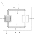
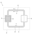
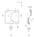
図4は、本実施形態に係るループ型ヒートパイプの上面図である。
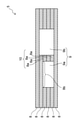
図19は、第1変形例に係るループ型ヒートパイプ11の側面図である。
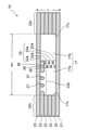
図20は、第2変形例に係るループ型ヒートパイプ11の側面図である。
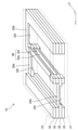
図21は、第3変形例に係るループ型ヒートパイプ11の蒸気管15の分解斜視図である。
図22は、第4変形例に係るループ型ヒートパイプ11の蒸気管15の分解斜視図である。
図23は、第5変形例に係るループ型ヒートパイプ11の蒸気管15の分解斜視図である。
図24は、第6変形例に係るループ型ヒートパイプ11の蒸気管15の分解斜視図である。
図25は、第7変形例に係るループ型ヒートパイプ11の蒸気管15の分解斜視図である。
図26は、第8変形例に係るループ型ヒートパイプ11の蒸気管15の分解斜視図である。
Claims (9)
- ループ状の管路と、
前記管路に封入された作動液と、
前記管路に設けられ、前記作動液を蒸発させる蒸発器と、
前記管路に設けられ、前記作動液の蒸気を凝縮させる凝縮器と、
前記蒸発器と前記凝縮器との間の前記管路であって、前記作動液の蒸気が流れる蒸気管と、
前記蒸発器と前記凝縮器との間の前記管路であって、液相の前記作動液が流れる液管と、を備えたループ型ヒートパイプであって、
前記管路の管壁を画定する管壁部と、前記管路のうち少なくとも前記蒸気管の内部に設けられた支柱部とを備え、各々が積層された複数の中間金属層と、
複数の前記中間金属層の各々の前記支柱部によって前記蒸気管に沿って延びるように形成され、平面視で前記管路を第1の流路と第2の流路とに分けると共に、前記第1の流路と前記第2の流路とを接続する第1の開口部が形成された支柱と、
最下層の前記中間金属層の下に接合され、前記管路を下から塞ぐ下側金属層と、
最上層の前記中間金属層の上に接合され、前記管路を上から塞ぐ上側金属層と、
を有し、
前記支柱部は、凹部が形成された下面と、前記下面に相対する上面とを有し、
上下に隣接する二つの前記支柱部のうち、下側の前記支柱部の前記上面と、上側の前記支柱部の前記凹部とにより前記第1の開口部が画定されたループ型ヒートパイプ。 - ループ状の管路と、
前記管路に封入された作動液と、
前記管路に設けられ、前記作動液を蒸発させる蒸発器と、
前記管路に設けられ、前記作動液の蒸気を凝縮させる凝縮器と、
前記蒸発器と前記凝縮器との間の前記管路であって、前記作動液の蒸気が流れる蒸気管と、
前記蒸発器と前記凝縮器との間の前記管路であって、液相の前記作動液が流れる液管と、を備えたループ型ヒートパイプであって、
前記管路の管壁を画定する管壁部と、前記管路のうち少なくとも前記蒸気管の内部に設けられた支柱部とを備え、各々が積層された複数の中間金属層と、
複数の前記中間金属層の各々の前記支柱部によって前記蒸気管に沿って延びるように形成され、平面視で前記管路を第1の流路と第2の流路とに分けると共に、前記第1の流路と前記第2の流路とを接続する第1の開口部が形成された支柱と、
最下層の前記中間金属層の下に接合され、前記管路を下から塞ぐ下側金属層と、
最上層の前記中間金属層の上に接合され、前記管路を上から塞ぐ上側金属層と、
を有し、
前記支柱部は、複数の第1の穴が形成された下面と、前記下面に相対すると共に、各々が前記第1の穴に繋がる複数の第2の穴が形成された上面とを有し、
前記第1の穴と第2の穴とにより前記第1の開口部が画定されたループ型ヒートパイプ。 - 前記中間金属層に、前記管壁部と前記支柱部とを接続する接続部が設けられ、
前記接続部に、平面視で前記蒸気管の延在方向に沿って貫く第2の開口部が形成されたことを特徴とする請求項1又は2に記載のループ型ヒートパイプ。 - 上下に隣接する前記支柱部において、上側の前記支柱部が備える前記第1の穴と、下側の前記支柱部が備える前記第2の穴とが、平面視で相互に重なりつつ互いの位置がずれていることを特徴とする請求項2に記載のループ型ヒートパイプ。
- 前記凹部は、前記蒸気管の延在方向に沿って複数設けられたことを特徴とする請求項1に記載のループ型ヒートパイプ。
- 上下に隣接する二つの前記支柱部のうち、下側の前記支柱部の上面に第1の凹部が形成され、かつ上側の前記支柱部の下面に第2の凹部が形成され、
前記第1の凹部と前記第2の凹部とにより前記第1の開口部が画定されたことを特徴とする請求項1に記載のループ型ヒートパイプ。 - 最下層の前記支柱部の前記下面は、前記蒸気管の延在方向に沿って前記下側金属層に接合されたストライプ状であり、
最上層の前記支柱部の前記上面は、前記延在方向に沿って前記上側金属層に接合されたストライプ状であることを特徴とする請求項6に記載のループ型ヒートパイプ。 - 最下層の前記支柱部に、前記下側金属層の表面と相対する凹部が形成され、前記凹部によって前記第1の流路と前記第2の流路とが接続されたことを特徴とする請求項1に記載のループ型ヒートパイプ。
- 前記支柱部は、前記蒸気管の延在方向に沿って交互に連なる凹部と凸部とが形成された下面と、前記下面に相対する上面とを有し、
上下に隣接する前記支柱部において、上側の前記支柱部が備える前記凹部と、下側の前記支柱部の前記上面とにより前記第1の開口部が複数確定され、
上側の前記支柱部が備える前記凸部と下側の前記支柱部の前記上面との間の接合強度が、上下に隣接する前記管壁部同士の接合強度よりも弱いことを特徴とする請求項1に記載のループ型ヒートパイプ。
Priority Applications (4)
| Application Number | Priority Date | Filing Date | Title |
|---|---|---|---|
| JP2018032871A JP6991892B2 (ja) | 2018-02-27 | 2018-02-27 | ループ型ヒートパイプ |
| US16/276,940 US10883770B2 (en) | 2018-02-27 | 2019-02-15 | Loop type heat pipe |
| EP19159121.3A EP3531056B1 (en) | 2018-02-27 | 2019-02-25 | Loop type heat pipe |
| CN201910141545.7A CN110195989B (zh) | 2018-02-27 | 2019-02-26 | 环路式热管 |
Applications Claiming Priority (1)
| Application Number | Priority Date | Filing Date | Title |
|---|---|---|---|
| JP2018032871A JP6991892B2 (ja) | 2018-02-27 | 2018-02-27 | ループ型ヒートパイプ |
Publications (2)
| Publication Number | Publication Date |
|---|---|
| JP2019148369A JP2019148369A (ja) | 2019-09-05 |
| JP6991892B2 true JP6991892B2 (ja) | 2022-01-13 |
Family
ID=65576218
Family Applications (1)
| Application Number | Title | Priority Date | Filing Date |
|---|---|---|---|
| JP2018032871A Active JP6991892B2 (ja) | 2018-02-27 | 2018-02-27 | ループ型ヒートパイプ |
Country Status (4)
| Country | Link |
|---|---|
| US (1) | US10883770B2 (ja) |
| EP (1) | EP3531056B1 (ja) |
| JP (1) | JP6991892B2 (ja) |
| CN (1) | CN110195989B (ja) |
Families Citing this family (2)
| Publication number | Priority date | Publication date | Assignee | Title |
|---|---|---|---|---|
| JP7015197B2 (ja) * | 2018-03-26 | 2022-02-02 | 新光電気工業株式会社 | ループ型ヒートパイプ及びその製造方法 |
| CN112254558B (zh) * | 2020-09-11 | 2021-05-18 | 深圳市银宝山新科技股份有限公司 | 三维叠层热管及其制备方法 |
Citations (6)
| Publication number | Priority date | Publication date | Assignee | Title |
|---|---|---|---|---|
| JP2002267378A (ja) | 2001-03-12 | 2002-09-18 | Showa Denko Kk | ヒートパイプ |
| WO2015087451A1 (ja) | 2013-12-13 | 2015-06-18 | 富士通株式会社 | ループ型ヒートパイプとその製造方法、及び電子機器 |
| JP2015183880A (ja) | 2014-03-20 | 2015-10-22 | 富士通株式会社 | ループ型ヒートパイプとその製造方法、及び電子機器 |
| JP2015200465A (ja) | 2014-04-09 | 2015-11-12 | 富士通株式会社 | ヒートパイプ内蔵フレーム板及び電子機器 |
| JP2016023866A (ja) | 2014-07-22 | 2016-02-08 | 株式会社フジクラ | ループ型サーモサイホン |
| JP2016142416A (ja) | 2015-01-29 | 2016-08-08 | 富士通株式会社 | ループヒートパイプ及びループヒートパイプの製造方法 |
Family Cites Families (13)
| Publication number | Priority date | Publication date | Assignee | Title |
|---|---|---|---|---|
| JPS6383587A (ja) * | 1986-09-29 | 1988-04-14 | Toshiba Corp | 平板形ヒ−トパイプ |
| JPH0254066U (ja) * | 1988-10-13 | 1990-04-19 | ||
| JP3381130B2 (ja) * | 1995-12-28 | 2003-02-24 | 昭和電工株式会社 | 偏平状熱交換管の製造方法 |
| JP2002327993A (ja) | 2001-05-01 | 2002-11-15 | Fujitsu Ltd | 薄型ヒートパイプ、薄型ヒートシンク、熱制御システムおよび薄型ヒートパイプの製造方法 |
| US6804117B2 (en) * | 2002-08-14 | 2004-10-12 | Thermal Corp. | Thermal bus for electronics systems |
| CN101472450A (zh) * | 2007-12-29 | 2009-07-01 | 私立淡江大学 | 可增强支撑强度与毛细作用的均热装置 |
| CN101927426A (zh) * | 2009-06-24 | 2010-12-29 | 富准精密工业(深圳)有限公司 | 均温板及其制造方法 |
| EP2522047A1 (en) * | 2010-01-08 | 2012-11-14 | Dow Global Technologies LLC | Thermal management of an electrochemical cell by a combination of heat transfer fluid and phase change material |
| US20120048516A1 (en) | 2010-08-27 | 2012-03-01 | Forcecon Technology Co., Ltd. | Flat heat pipe with composite capillary structure |
| US9646915B2 (en) | 2012-07-18 | 2017-05-09 | Kyocera Corporation | Heat dissipation device and semiconductor device |
| CN204678937U (zh) * | 2015-03-03 | 2015-09-30 | 湖南中科热控技术有限公司 | 一种环路热管的蒸发器和散热装置 |
| JP6291000B2 (ja) * | 2016-09-01 | 2018-03-07 | 新光電気工業株式会社 | ループ型ヒートパイプ及びその製造方法 |
| JP6691467B2 (ja) * | 2016-11-18 | 2020-04-28 | 新光電気工業株式会社 | ループ型ヒートパイプ及びその製造方法 |
-
2018
- 2018-02-27 JP JP2018032871A patent/JP6991892B2/ja active Active
-
2019
- 2019-02-15 US US16/276,940 patent/US10883770B2/en active Active
- 2019-02-25 EP EP19159121.3A patent/EP3531056B1/en active Active
- 2019-02-26 CN CN201910141545.7A patent/CN110195989B/zh active Active
Patent Citations (6)
| Publication number | Priority date | Publication date | Assignee | Title |
|---|---|---|---|---|
| JP2002267378A (ja) | 2001-03-12 | 2002-09-18 | Showa Denko Kk | ヒートパイプ |
| WO2015087451A1 (ja) | 2013-12-13 | 2015-06-18 | 富士通株式会社 | ループ型ヒートパイプとその製造方法、及び電子機器 |
| JP2015183880A (ja) | 2014-03-20 | 2015-10-22 | 富士通株式会社 | ループ型ヒートパイプとその製造方法、及び電子機器 |
| JP2015200465A (ja) | 2014-04-09 | 2015-11-12 | 富士通株式会社 | ヒートパイプ内蔵フレーム板及び電子機器 |
| JP2016023866A (ja) | 2014-07-22 | 2016-02-08 | 株式会社フジクラ | ループ型サーモサイホン |
| JP2016142416A (ja) | 2015-01-29 | 2016-08-08 | 富士通株式会社 | ループヒートパイプ及びループヒートパイプの製造方法 |
Also Published As
| Publication number | Publication date |
|---|---|
| EP3531056B1 (en) | 2021-05-05 |
| CN110195989A (zh) | 2019-09-03 |
| US20190264988A1 (en) | 2019-08-29 |
| JP2019148369A (ja) | 2019-09-05 |
| US10883770B2 (en) | 2021-01-05 |
| CN110195989B (zh) | 2021-12-28 |
| EP3531056A1 (en) | 2019-08-28 |
Similar Documents
| Publication | Publication Date | Title |
|---|---|---|
| US10704838B2 (en) | Loop heat pipe | |
| JP6691467B2 (ja) | ループ型ヒートパイプ及びその製造方法 | |
| CN110118499B (zh) | 环路热管及其制造方法 | |
| JP7204374B2 (ja) | ループ型ヒートパイプ及びその製造方法 | |
| JP7236825B2 (ja) | ループ型ヒートパイプ及びその製造方法 | |
| JP7015197B2 (ja) | ループ型ヒートパイプ及びその製造方法 | |
| US11060798B2 (en) | Loop heat pipe | |
| JP7155585B2 (ja) | ベーパーチャンバー、及び電子機器 | |
| JP7146524B2 (ja) | ループ型ヒートパイプ及びその製造方法 | |
| CN110118501A (zh) | 环路热管及其制造方法 | |
| CN109724438A (zh) | 环路式热管 | |
| EP3428565B1 (en) | Loop heat pipe and method of manufacturing loop heat pipe | |
| JP7305512B2 (ja) | ループ型ヒートパイプ及びその製造方法 | |
| JP6951267B2 (ja) | ヒートパイプ及びその製造方法 | |
| JP6991892B2 (ja) | ループ型ヒートパイプ | |
| US11105562B2 (en) | Loop-type heat pipe | |
| JP6999452B2 (ja) | ループ型ヒートパイプ、及びループ型ヒートパイプ製造方法 | |
| JP6852352B2 (ja) | ループヒートパイプ及び電子機器 | |
| JP2019015420A (ja) | ヒートパイプ及びヒートパイプの製造方法 | |
| JP7353132B2 (ja) | ループ型ヒートパイプ及びその製造方法 | |
| JP7372185B2 (ja) | ループ型ヒートパイプ及びその製造方法 | |
| JP2023012839A5 (ja) |
Legal Events
| Date | Code | Title | Description |
|---|---|---|---|
| RD03 | Notification of appointment of power of attorney |
Free format text: JAPANESE INTERMEDIATE CODE: A7423 Effective date: 20180320 |
|
| A621 | Written request for application examination |
Free format text: JAPANESE INTERMEDIATE CODE: A621 Effective date: 20201118 |
|
| A977 | Report on retrieval |
Free format text: JAPANESE INTERMEDIATE CODE: A971007 Effective date: 20210730 |
|
| A131 | Notification of reasons for refusal |
Free format text: JAPANESE INTERMEDIATE CODE: A131 Effective date: 20210810 |
|
| A521 | Request for written amendment filed |
Free format text: JAPANESE INTERMEDIATE CODE: A523 Effective date: 20211006 |
|
| TRDD | Decision of grant or rejection written | ||
| A01 | Written decision to grant a patent or to grant a registration (utility model) |
Free format text: JAPANESE INTERMEDIATE CODE: A01 Effective date: 20211124 |
|
| A61 | First payment of annual fees (during grant procedure) |
Free format text: JAPANESE INTERMEDIATE CODE: A61 Effective date: 20211208 |
|
| R150 | Certificate of patent or registration of utility model |
Ref document number: 6991892 Country of ref document: JP Free format text: JAPANESE INTERMEDIATE CODE: R150 |