JP6991892B2 - Loop type heat pipe - Google Patents
Loop type heat pipe Download PDFInfo
- Publication number
- JP6991892B2 JP6991892B2 JP2018032871A JP2018032871A JP6991892B2 JP 6991892 B2 JP6991892 B2 JP 6991892B2 JP 2018032871 A JP2018032871 A JP 2018032871A JP 2018032871 A JP2018032871 A JP 2018032871A JP 6991892 B2 JP6991892 B2 JP 6991892B2
- Authority
- JP
- Japan
- Prior art keywords
- pipe
- metal layer
- pipeline
- type heat
- heat pipe
- Prior art date
- Legal status (The legal status is an assumption and is not a legal conclusion. Google has not performed a legal analysis and makes no representation as to the accuracy of the status listed.)
- Active
Links
Images


Classifications
-
- F—MECHANICAL ENGINEERING; LIGHTING; HEATING; WEAPONS; BLASTING
- F28—HEAT EXCHANGE IN GENERAL
- F28D—HEAT-EXCHANGE APPARATUS, NOT PROVIDED FOR IN ANOTHER SUBCLASS, IN WHICH THE HEAT-EXCHANGE MEDIA DO NOT COME INTO DIRECT CONTACT
- F28D15/00—Heat-exchange apparatus with the intermediate heat-transfer medium in closed tubes passing into or through the conduit walls ; Heat-exchange apparatus employing intermediate heat-transfer medium or bodies
- F28D15/02—Heat-exchange apparatus with the intermediate heat-transfer medium in closed tubes passing into or through the conduit walls ; Heat-exchange apparatus employing intermediate heat-transfer medium or bodies in which the medium condenses and evaporates, e.g. heat pipes
- F28D15/0266—Heat-exchange apparatus with the intermediate heat-transfer medium in closed tubes passing into or through the conduit walls ; Heat-exchange apparatus employing intermediate heat-transfer medium or bodies in which the medium condenses and evaporates, e.g. heat pipes with separate evaporating and condensing chambers connected by at least one conduit; Loop-type heat pipes; with multiple or common evaporating or condensing chambers
-
- F—MECHANICAL ENGINEERING; LIGHTING; HEATING; WEAPONS; BLASTING
- F28—HEAT EXCHANGE IN GENERAL
- F28D—HEAT-EXCHANGE APPARATUS, NOT PROVIDED FOR IN ANOTHER SUBCLASS, IN WHICH THE HEAT-EXCHANGE MEDIA DO NOT COME INTO DIRECT CONTACT
- F28D15/00—Heat-exchange apparatus with the intermediate heat-transfer medium in closed tubes passing into or through the conduit walls ; Heat-exchange apparatus employing intermediate heat-transfer medium or bodies
- F28D15/02—Heat-exchange apparatus with the intermediate heat-transfer medium in closed tubes passing into or through the conduit walls ; Heat-exchange apparatus employing intermediate heat-transfer medium or bodies in which the medium condenses and evaporates, e.g. heat pipes
- F28D15/0233—Heat-exchange apparatus with the intermediate heat-transfer medium in closed tubes passing into or through the conduit walls ; Heat-exchange apparatus employing intermediate heat-transfer medium or bodies in which the medium condenses and evaporates, e.g. heat pipes the conduits having a particular shape, e.g. non-circular cross-section, annular
-
- F—MECHANICAL ENGINEERING; LIGHTING; HEATING; WEAPONS; BLASTING
- F28—HEAT EXCHANGE IN GENERAL
- F28D—HEAT-EXCHANGE APPARATUS, NOT PROVIDED FOR IN ANOTHER SUBCLASS, IN WHICH THE HEAT-EXCHANGE MEDIA DO NOT COME INTO DIRECT CONTACT
- F28D15/00—Heat-exchange apparatus with the intermediate heat-transfer medium in closed tubes passing into or through the conduit walls ; Heat-exchange apparatus employing intermediate heat-transfer medium or bodies
- F28D15/02—Heat-exchange apparatus with the intermediate heat-transfer medium in closed tubes passing into or through the conduit walls ; Heat-exchange apparatus employing intermediate heat-transfer medium or bodies in which the medium condenses and evaporates, e.g. heat pipes
- F28D15/04—Heat-exchange apparatus with the intermediate heat-transfer medium in closed tubes passing into or through the conduit walls ; Heat-exchange apparatus employing intermediate heat-transfer medium or bodies in which the medium condenses and evaporates, e.g. heat pipes with tubes having a capillary structure
- F28D15/043—Heat-exchange apparatus with the intermediate heat-transfer medium in closed tubes passing into or through the conduit walls ; Heat-exchange apparatus employing intermediate heat-transfer medium or bodies in which the medium condenses and evaporates, e.g. heat pipes with tubes having a capillary structure forming loops, e.g. capillary pumped loops
-
- F—MECHANICAL ENGINEERING; LIGHTING; HEATING; WEAPONS; BLASTING
- F28—HEAT EXCHANGE IN GENERAL
- F28F—DETAILS OF HEAT-EXCHANGE AND HEAT-TRANSFER APPARATUS, OF GENERAL APPLICATION
- F28F1/00—Tubular elements; Assemblies of tubular elements
-
- F—MECHANICAL ENGINEERING; LIGHTING; HEATING; WEAPONS; BLASTING
- F28—HEAT EXCHANGE IN GENERAL
- F28F—DETAILS OF HEAT-EXCHANGE AND HEAT-TRANSFER APPARATUS, OF GENERAL APPLICATION
- F28F21/00—Constructions of heat-exchange apparatus characterised by the selection of particular materials
- F28F21/08—Constructions of heat-exchange apparatus characterised by the selection of particular materials of metal
- F28F21/089—Coatings, claddings or bonding layers made from metals or metal alloys
-
- F—MECHANICAL ENGINEERING; LIGHTING; HEATING; WEAPONS; BLASTING
- F28—HEAT EXCHANGE IN GENERAL
- F28F—DETAILS OF HEAT-EXCHANGE AND HEAT-TRANSFER APPARATUS, OF GENERAL APPLICATION
- F28F3/00—Plate-like or laminated elements; Assemblies of plate-like or laminated elements
- F28F3/08—Elements constructed for building-up into stacks, e.g. capable of being taken apart for cleaning
- F28F3/086—Elements constructed for building-up into stacks, e.g. capable of being taken apart for cleaning having one or more openings therein forming tubular heat-exchange passages
-
- F—MECHANICAL ENGINEERING; LIGHTING; HEATING; WEAPONS; BLASTING
- F28—HEAT EXCHANGE IN GENERAL
- F28F—DETAILS OF HEAT-EXCHANGE AND HEAT-TRANSFER APPARATUS, OF GENERAL APPLICATION
- F28F3/00—Plate-like or laminated elements; Assemblies of plate-like or laminated elements
- F28F3/12—Elements constructed in the shape of a hollow panel, e.g. with channels
-
- H—ELECTRICITY
- H05—ELECTRIC TECHNIQUES NOT OTHERWISE PROVIDED FOR
- H05K—PRINTED CIRCUITS; CASINGS OR CONSTRUCTIONAL DETAILS OF ELECTRIC APPARATUS; MANUFACTURE OF ASSEMBLAGES OF ELECTRICAL COMPONENTS
- H05K7/00—Constructional details common to different types of electric apparatus
- H05K7/20—Modifications to facilitate cooling, ventilating, or heating
- H05K7/2029—Modifications to facilitate cooling, ventilating, or heating using a liquid coolant with phase change in electronic enclosures
- H05K7/20336—Heat pipes, e.g. wicks or capillary pumps
-
- H—ELECTRICITY
- H10—SEMICONDUCTOR DEVICES; ELECTRIC SOLID-STATE DEVICES NOT OTHERWISE PROVIDED FOR
- H10W—GENERIC PACKAGES, INTERCONNECTIONS, CONNECTORS OR OTHER CONSTRUCTIONAL DETAILS OF DEVICES COVERED BY CLASS H10
- H10W40/00—Arrangements for thermal protection or thermal control
- H10W40/70—Fillings or auxiliary members in containers or in encapsulations for thermal protection or control
- H10W40/73—Fillings or auxiliary members in containers or in encapsulations for thermal protection or control for cooling by change of state
-
- H—ELECTRICITY
- H10—SEMICONDUCTOR DEVICES; ELECTRIC SOLID-STATE DEVICES NOT OTHERWISE PROVIDED FOR
- H10W—GENERIC PACKAGES, INTERCONNECTIONS, CONNECTORS OR OTHER CONSTRUCTIONAL DETAILS OF DEVICES COVERED BY CLASS H10
- H10W40/00—Arrangements for thermal protection or thermal control
- H10W40/01—Manufacture or treatment
- H10W40/03—Manufacture or treatment of arrangements for cooling
- H10W40/037—Assembling together parts thereof
Landscapes
- Engineering & Computer Science (AREA)
- Physics & Mathematics (AREA)
- Thermal Sciences (AREA)
- Mechanical Engineering (AREA)
- General Engineering & Computer Science (AREA)
- Life Sciences & Earth Sciences (AREA)
- Sustainable Development (AREA)
- Microelectronics & Electronic Packaging (AREA)
- Cooling Or The Like Of Semiconductors Or Solid State Devices (AREA)
- Cooling Or The Like Of Electrical Apparatus (AREA)
Description
本発明は、ループ型ヒートパイプに関する。 The present invention relates to a loop type heat pipe.
スマートフォン等のモバイル型の電子機器で発生した熱を輸送するデバイスとしてループ型ヒートパイプがある。ループ型ヒートパイプは、作動液の相変化を利用して熱輸送を行うデバイスであって、作動液が封入されたループ状の管路を有する。 There is a loop type heat pipe as a device for transporting heat generated by a mobile electronic device such as a smartphone. The loop type heat pipe is a device that transports heat by utilizing the phase change of the hydraulic fluid, and has a loop-shaped pipeline in which the hydraulic fluid is sealed.
管路の形成方法には幾つかの方法がある。なかでも、複数の薄い金属板を積層してその内部に管路を形成する方法では、モバイル型の電子機器に適した薄い管路を形成することができるため、電子機器の薄型化を進めることができる。 There are several methods for forming a pipeline. Among them, the method of laminating a plurality of thin metal plates to form a pipeline inside the thin metal plate can form a thin pipeline suitable for a mobile electronic device, so that the thinning of the electronic device should be promoted. Can be done.
そのように薄い管路が製造途中で潰れてしまうと管路内の圧力損失が高まり、ループ型ヒートパイプの内部を作動液が循環するのが困難となる。そのため、管路内に支柱を設けることにより、管路が潰れるのを支柱で防止する技術が検討されている。 If such a thin pipeline is crushed during manufacturing, the pressure loss in the pipeline increases, and it becomes difficult for the hydraulic fluid to circulate inside the loop type heat pipe. Therefore, a technique for preventing the pipeline from being crushed by providing a support in the pipeline is being studied.
しかしながら、このように管路の内部に支柱を設けると、作動液の蒸気が管路内を流通し難くなるため、管路内の圧力損失が高まってしまい、ループ型ヒートパイプの熱輸送能力が低下してしまう。 However, if a support column is provided inside the pipeline in this way, it becomes difficult for the vapor of the hydraulic fluid to flow through the pipeline, so that the pressure loss in the pipeline increases and the heat transport capacity of the loop type heat pipe increases. It will drop.
一側面によれば、本発明は、ループ型ヒートパイプの管路が潰れるのを防止しつつ、ループ型ヒートパイプの熱輸送能力が低下するのを抑制することを目的とする。 According to one aspect, it is an object of the present invention to prevent the pipeline of the loop type heat pipe from being crushed and to suppress the decrease in the heat transport capacity of the loop type heat pipe.
一側面によれば、ループ状の管路と、前記管路に封入された作動液と、前記管路に設けられ、前記作動液を蒸発させる蒸発器と、前記管路に設けられ、前記作動液の蒸気を凝縮させる凝縮器と、前記蒸発器と前記凝縮器との間の前記管路であって、前記作動液の蒸気が流れる蒸気管と、前記蒸発器と前記凝縮器との間の前記管路であって、液相の前記作動液が流れる液管と、を備えたループ型ヒートパイプであって、前記管路の管壁を画定する管壁部と、前記管路のうち少なくとも前記蒸気管の内部に設けられた支柱部とを備え、各々が積層された複数の中間金属層と、複数の前記中間金属層の各々の前記支柱部によって前記蒸気管に沿って延びるように形成され、平面視で前記管路を第1の流路と第2の流路とに分けると共に、前記第1の流路と前記第2の流路とを接続する第1の開口部が形成された支柱と、最下層の前記中間金属層の下に接合され、前記管路を下から塞ぐ下側金属層と、最上層の前記中間金属層の上に接合され、前記管路を上から塞ぐ上側金属層と、を有し、前記支柱部は、凹部が形成された下面と、前記下面に相対する上面とを有し、上下に隣接する二つの前記支柱部のうち、下側の前記支柱部の前記上面と、上側の前記支柱部の前記凹部とにより前記第1の開口部が画定されたループ型ヒートパイプが提供される。 According to one aspect, a loop-shaped conduit, a working fluid enclosed in the conduit, an evaporator provided in the conduit to evaporate the working fluid, and an actuation provided in the conduit. Between the condenser that condenses the vapor of the liquid, the pipe line between the evaporator and the condenser, the steam pipe through which the vapor of the working liquid flows, and the evaporator and the condenser. A loop-type heat pipe including a pipe through which the working liquid of the liquid phase flows, the pipe wall portion defining the pipe wall of the pipe, and at least one of the pipes. It is provided with a strut portion provided inside the steam pipe, and is formed so as to extend along the steam pipe by a plurality of intermediate metal layers in which each is laminated and a strut portion of each of the plurality of intermediate metal layers. Then, in a plan view, the pipeline is divided into a first flow path and a second flow path, and a first opening connecting the first flow path and the second flow path is formed. It is joined to the support column and the lower metal layer which is joined under the intermediate metal layer of the lowermost layer and closes the pipeline from below, and is joined to the intermediate metal layer of the uppermost layer and closes the pipeline from above. It has an upper metal layer, and the strut portion has a lower surface on which a recess is formed and an upper surface facing the lower surface, and is the lower strut of the two vertically adjacent strut portions. A loop type heat pipe in which the first opening is defined by the upper surface of the portion and the recess of the upper support column portion is provided.
一側面によれば、支柱部に第1の開口部を形成したことにより管路内の圧力損失が上昇するのを防止でき、ループ型ヒートパイプの熱輸送能力が低下するのを抑制することができる。 According to one aspect, it is possible to prevent the pressure loss in the pipeline from increasing due to the formation of the first opening in the column portion, and to suppress the decrease in the heat transport capacity of the loop type heat pipe. can.
本実施形態の説明に先立ち、本願発明者が検討した事項について説明する。 Prior to the description of the present embodiment, the matters examined by the inventor of the present application will be described.
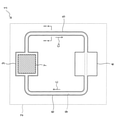
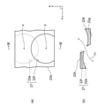
図1は、検討に使用したループ型ヒートパイプの上面図である。 FIG. 1 is a top view of the loop type heat pipe used in the study.
このループ型ヒートパイプ1は、スマートフォンやデジタルカメラ等の筐体2に収容されており、蒸発器3と凝縮器4とを備える。
The loop
蒸発器3と凝縮器4には蒸気管5と液管6とが接続されており、これらの管5、6によって作動液Cが流れるループ状の管路9が形成される。また、蒸発器3にはCPU(Central Processing Unit)等の発熱部品7が固着されており、その発熱部品7の熱により作動液Cの蒸気Cvが生成される。
A
その蒸気Cvは、蒸気管5を通って凝縮器4に導かれ、凝縮器4において液化した後に液管6を通って再び蒸発器3に供給される。
The steam Cv is guided to the condenser 4 through the
このようにループ型ヒートパイプ1の内部を作動液Cが循環することにより発熱部品7で発生した熱が凝縮器4に移動し、発熱部品7の冷却を促すことができる。
As the hydraulic fluid C circulates inside the loop
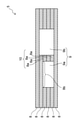
図2は、図1のI-I線に沿った蒸気管5の断面図である。
FIG. 2 is a cross-sectional view of the
図2に示すように、この例では複数の金属層8の積層体を加熱しながら上下から加圧し、各金属層8同士を金属間接合により接合して管路9を形成する。また、最下層と最上層とを除いた各金属層8には支柱部8aが形成されており、各支柱部8aの積層体によって支柱10が形成される。支柱10は、上記のように各金属層8を加圧する際に蒸気管5が潰れるのを防止するように機能する。また、後述のように管路9を曲げる場合であっても、曲げたときに管路9が潰れるのを防止するのを支柱10で防止できる。そして、その支柱10によって管路9が第1の流路9aと第2の流路9bとに分けられる。
As shown in FIG. 2, in this example, the laminated body of a plurality of
なお、金属層8はウエットエッチングにより銅層等をパターニングすることにより形成されるが、そのウエットエッチング時に支柱部8aが金属層8から脱離するのを防止するための接続部8bが各金属層8に設けられる。
The
図3は、支柱部8aが形成された一枚の金属層8の拡大平面図である。
FIG. 3 is an enlarged plan view of a
図3に示すように、支柱部8aは管路9に沿って延びるように形成される。また、支柱部8aが接続部8bを介して金属層8に支持されるため、支柱部8aと金属層8とを一体的に扱うことができる。
As shown in FIG. 3, the
なお、接続部8bの位置を全ての金属層8で同一とすると、接続部8bによって管路9が閉塞してしまうため、金属層8ごとに接続部8bの位置を変えるのが好ましい。
If the positions of the connecting
このようなループ型ヒートパイプ1によれば、上記のように金属層8を積層することでループ型ヒートパイプ1の厚さを薄くすることができ、筐体2の薄型化を推し進めることが可能となる。
According to such a loop
しかも、蒸気管5の内部に支柱10を形成したため、各金属層8を加圧して接合するときの圧力で蒸気管5が潰れるのを支柱10で防止することが可能となり、蒸気管5が潰れて蒸気Cvの流れがループ型ヒートパイプ1内で滞るのを防止できる。
Moreover, since the
しかしながら、このように支柱10を形成すると、蒸気管5における蒸気Cvの流れが支柱10で阻害されてしまうため、蒸気管5における圧力損失が上昇し、ループ型ヒートパイプ1の熱輸送効率が低下することになる。
However, when the
更に、接続部8bが形成された部分の蒸気管5においては、接続部8bによって管路9の断面積が狭くなり、蒸気管5の圧力損失が更に上昇してしまう。
Further, in the
以下に、ループ型ヒートパイプの熱輸送能力が低下するのを抑制することが可能な本実施形態について説明する。 Hereinafter, the present embodiment capable of suppressing a decrease in the heat transport capacity of the loop type heat pipe will be described.
(本実施形態)
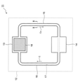
図4は、本実施形態に係るループ型ヒートパイプの上面図である。
(The present embodiment)
FIG. 4 is a top view of the loop type heat pipe according to the present embodiment.
このループ型ヒートパイプ11は、電子機器の筐体12に収容されており、蒸発器13と凝縮器14とを備える。電子機器は、冷却対象の発熱部品を有する機器であれば特に限定されず、スマートフォン、デジタルカメラ、人工衛星、車載電子機器、及びサーバ等を電子機器として採用し得る。
The loop
蒸発器13と凝縮器14には蒸気管15と液管16とが接続されており、これらの管15、16によって作動液Cが流れるループ状の管路17が形成される。また、蒸発器13にはCPU等の発熱部品18が固着されており、その発熱部品18の熱により作動液Cの蒸気Cvが生成される。
A
蒸気Cvは、蒸気管15を通って凝縮器14に導かれ、凝縮器14において液化した後に液管16を通って再び蒸発器13に供給される。
The steam Cv is guided to the
ループ型ヒートパイプ11の内部をこのように作動液Cが循環することにより発熱部品18で発生した熱が凝縮器14に移動し、発熱部品18の冷却を促すことができる。
As the hydraulic fluid C circulates inside the loop
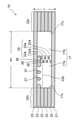
図5は、図4のII-II線に沿った蒸気管15の断面図である。
FIG. 5 is a cross-sectional view of the
図5に示すように、本実施形態では下側金属層21、複数の中間金属層22、及び上側金属層23をこの順に積層してループ型ヒートパイプ11を作製する。
As shown in FIG. 5, in the present embodiment, the
これらの金属層のうち、複数の中間金属層22の各々には支柱25を構成する支柱部22aが形成されており、その支柱25によって管路17が第1の流路17aと第2の流路17bとに分けられる。
Of these metal layers, each of the plurality of intermediate metal layers 22 is formed with a
また、各中間金属層22には管路17の管壁17xを画定する管壁部22cが設けられており、更に下側金属層21がその管路17を下側から塞ぐと共に、上側金属層23が管路17を上から塞ぐ。なお、最上層の中間金属層22には、支柱部22aに接続された接続部22bが設けられる。そのような接続部22bは、最上層の中間金属層22だけでなく、各々の中間金属層22にも形成される。
Further, each
そして、下側金属層21と上側金属層23の各々は支柱25に接合されており、これにより各金属層21~23を積層するときの圧力で管路17が潰れるのを防止できる。また、接続部22bにより各中間金属層22と支柱部22aとを接続したため、一枚の金属層に中間金属層22と支柱部22aとを形成しても、その支柱部22aが中間金属層22から脱離するのを防止できる。
Each of the
なお、管路17において支柱25を形成する部位は特に限定されないが、この例のように内部が空洞で潰れやすい蒸気管15に支柱25を形成するのが好ましい。同じ理由により凝縮器14(図4参照)における管路17にも支柱25を形成してもよい。
The portion of the
一方、液管16(図4参照)の内部には、液相の作動液Cを毛細管力で蒸発器13に移動させるための不図示のウィックが形成されており、そのウィックで液管16が補強されているため、液管16には支柱25を設けなくてもよい。
On the other hand, inside the liquid tube 16 (see FIG. 4), a wick (not shown) for moving the hydraulic fluid C of the liquid phase to the
また、管路17の幅W1は、ループ型ヒートパイプ11に求められる熱輸送性能等にもよるが、この例では例えば5mm~10mm程度とする。
Further, the width W1 of the
各金属層21~23の材料も特に限定されず、熱伝導性と加工性が良好な銅層を各金属層21~23として採用し得る。なお、銅層に代えてアルミニウム層やステンレス層を各金属層21~23として採用してもよい。
The material of each
更に、各金属層21~23のそれぞれの厚さは100μm~300μm、例えば100μm程度であり、各金属層21~23を合わせた合計の厚さTは600μm~1800μm程度である。
Further, the thickness of each of the metal layers 21 to 23 is about 100 μm to 300 μm, for example, about 100 μm, and the total thickness T of each
このように厚さが薄い各金属層21~23を積層することでループ型ヒートパイプ11の厚さを薄くすることができ、ループ型ヒートパイプ11が収容される筐体12の薄型化に寄与することができる。
By laminating the
また、この例では支柱部22aや接続部22bによって管路17における圧力損失が上昇するのを防止するために、支柱部22aに第1の開口部26を形成すると共に、接続部22bに第2の開口部27を形成する。
Further, in this example, in order to prevent the pressure loss in the
図6は、蒸気管15における中間金属層22の拡大平面図である。
FIG. 6 is an enlarged plan view of the
図6に示すように、支柱部22aは、管路17の延在方向Xに沿って延びるように形成される。支柱部22aの幅W2は特に限定されないが、この例では幅W2を500μm~3000μm程度とする。
As shown in FIG. 6, the
そして、第1の開口部26は、第1の流路17aと第2の流路17bとを接続するように支柱部22aに形成される。これにより、第1の開口部26を通じて蒸気Cvが各流路17a、17bの間を流通できるようになると共に、第1の開口部26の分だけ管路17の断面積が増加するため、管路17における蒸気Cvの圧力損失を低減することができる。
The
一方、接続部22bは、延在方向Xに直交する方向Yに沿って延びており、その幅W3は例えば500μm~2000μm程度である。そして、第2の開口部27は、延在方向Xに沿って接続部22bを貫くように形成されており、その内部を蒸気Cvが延在方向Xに沿って流れる。
On the other hand, the connecting
これにより、第2の開口部27がない場合と比較して各流路17a、17bを蒸気Cvが流れ易くなるため、管路17における蒸気Cvの圧力損失を更に低減することができる。
As a result, the steam Cv can easily flow through the
各開口部26、27の形状は特に限定されない。
The shape of each of the
図7(a)は第1の開口部26の拡大平面図であり、図7(b)は図7(a)のIII-III線に沿った断面図である。
7 (a) is an enlarged plan view of the
図7(a)に示すように、支柱部22aには第1の開口部26を構成する第1の穴22eと第2の穴22fとが形成される。これらの穴22e、22fは、いずれも有底であって、平面視で概略円形である。
As shown in FIG. 7A, a
この例では、各穴22e、22fを相互に接続しつつ、各穴22e、22fの各々の中心Pを前述の方向Yに沿ってずらすことにより、方向Yに沿って蒸気Cvが第1の開口部26を流れるようにする。
In this example, the steam Cv is first opened along the direction Y by shifting the center P of each of the
なお、各穴22e、22fの大きさは特に限定されないが、この例ではこれらの穴22e、22fの直径を200μm程度とする。
The sizes of the
また、図7(b)に示すように、第1の穴22eは支柱部22aの下面22gに形成されており、下面22gに相対する上面22hに第2の穴22fが形成される。これらの穴22e、22fは、銅層等の金属層をウエットエッチングで等方的にエッチングすることにより形成されるため、丸みを帯びた断面形状となる。
Further, as shown in FIG. 7B, the
一方、図8(a)は、第2の開口部27の拡大平面図であり、図8(b)は図8(a)のIV-IV線に沿った断面図である。
On the other hand, FIG. 8A is an enlarged plan view of the
図8(a)、(b)に示すように、第2の開口部27も前述の第1の穴22eと第2の穴22fにより構成される。
As shown in FIGS. 8A and 8B, the
但し、各穴22e、22fの各々の中心Pは前述の延在方向Xにずれており、これにより延在方向Xに沿って蒸気Cvが第2の開口部27を流れるようになる。
However, the center P of each of the
図9(a)は、各穴22e、22fが形成された一枚の中間金属層22の拡大写真を基にして描いた図であり、図9(b)は、その中間金属層22の断面の拡大写真を基にして描いた図である。
FIG. 9A is a diagram drawn based on an enlarged photograph of one
図9(a)に示すように、各穴22e、22fは、各々の中心をずらしながら相互に重複するように形成される。このうち、第1の穴22eの直径は前述のように200μm程度であり、第1の穴22eのピッチは300μm程度である。第2の穴22fもこれと同じ直径とピッチとを有する。
As shown in FIG. 9A, the
また、図9(b)に示されるように、各穴22e、22fは断面視で概略半球状である。
Further, as shown in FIG. 9B, the
図10は、上下に隣接する中間金属層22において、上側の中間金属層22における第1の穴22eと、下側の中間金属層22における第2の穴22fとの位置関係を示す平面図である。
FIG. 10 is a plan view showing the positional relationship between the
図10に示すように、この例では上側の中間金属層22における第1の穴22eと、下側の中間金属層22における第2の穴22fとを平面視で相互に重ねつつ互いの位置をずらす。
As shown in FIG. 10, in this example, the
これにより、各穴22e、22fの内部を蒸気Cvが三次元的に流れるようになり、上記の支柱25や接続部22bから蒸気Cvが受ける抵抗を低減することができるようになる。
As a result, the steam Cv flows three-dimensionally inside each of the
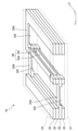
図11は、蒸気管15の分解斜視図である。
FIG. 11 is an exploded perspective view of the
図11に示すように、支柱部22aと接続部22bの各々には複数の開口部26、27が形成されており、これにより支柱部22aと接続部22bは多孔質となる。その結果、各流路17a、17bのうちの一方に溜まった液相の作動液Cを他方に排出するような毛細管力が多孔質状の支柱部22aから作動液Cに働くようになる。そのため、外気温の低下等によって各流路17a、17bのいずれか一方に液相の作動液Cが結露しても、その作動液Cが他方の流路に排出され易くなるため、管路17内に液溜まりが発生し難くなり、その液溜まりで管路17内の圧力損失が高まるのを防止できる。
As shown in FIG. 11, a plurality of
一方、接続部22bによって管路17が閉塞するのを防止するために、接続部22bは中間金属層22ごとに異なる位置に設けられる。
On the other hand, in order to prevent the
以上説明した本実施形態によれば、図5に示したように、各流路17a、17bを接続する第1の開口部26を支柱25に形成したため、第1の開口部26の分だけ管路17の断面積が増加し、管路17における蒸気Cvの圧力損失を低減することができる。
According to the present embodiment described above, as shown in FIG. 5, since the
しかも、接続部22bに第2の開口部27を形成したことで各流路17a、17bを蒸気Cvが流れ易くなり、管路17における蒸気Cvの圧力損失を更に低減することができる。
Moreover, by forming the
そして、このように管路17における圧力損失が低減することでループ型ヒートパイプ11の熱輸送効率が向上し、発熱部品18(図4参照)の温度上昇を効率的に抑制することが可能となる。
By reducing the pressure loss in the
なお、第1の開口部26のみで管路17における圧力損失を十分に低減できる場合には、接続部22bに第2の開口部27を形成しなくてもよい。
If the pressure loss in the
次に、本実施形態に係るループ型ヒートパイプ11の製造方法について説明する。
Next, a method for manufacturing the loop
図12~図14は、中間金属層22の製造方法について説明するための平面図である。また、図15及び図16は、中間金属層22の製造方法について説明するための断面図であって、図12~図14のV-V線に沿った断面図に相当する。
12 to 14 are plan views for explaining a method of manufacturing the
まず、図12及び図15(a)に示すように、金属層22yとして銅層を用意し、その両面に第1のレジスト層31と第2のレジスト層32を形成する。これらのレジスト層31、32は、平面視で中間金属層22と同じ輪郭を有すると共に、各穴22e、22fに対応した円形の第1のレジスト開口31aと第2のレジスト開口32aとを有する。
First, as shown in FIGS. 12 and 15 (a), a copper layer is prepared as the
次に、図13及び図15(b)に示すように、各レジスト層31、32をマスクにしながら、金属層22yをその両面からウエットエッチングする。これにより、金属層22yがパターニングされて中間金属層22になると共に、各レジスト開口31a、32aの下に相互に接続された穴22e、22fが形成される。また、そのウエットエッチングは等方的に進行するため、各穴22e、22fは半球状となる。
Next, as shown in FIGS. 13 and 15 (b), the
更に、この工程では、第1のレジスト層31と第2のレジスト層32の両方が形成されている部分の金属層22yがエッチングされずに管壁部22cとして残される。
Further, in this step, the
その後に、図14及び図16に示すように各レジスト層31、32を除去し、中間金属層22の基本構造を完成させる。
After that, as shown in FIGS. 14 and 16, the resist
これ以降の工程について図17及び図18を参照しながら説明する。 Subsequent steps will be described with reference to FIGS. 17 and 18.
図17及び図18は、本実施形態に係るループ型ヒートパイプ11の製造途中の断面図である。
17 and 18 are cross-sectional views of the loop
まず、図17に示すように、下側金属層21、複数の中間金属層22、及び上側金属層23をこの順に積層する。
First, as shown in FIG. 17, the
次に、図18に示すように、各金属層21~23を500℃以上の温度、例えば700℃に加熱しながら、10MPa程度の圧力で各金属層21~23同士をプレスする。これにより、各金属層21~23同士が金属間接合によって接合すると共に、下側金属層21と上側金属層23によって管路17が上下から塞がれる。
Next, as shown in FIG. 18, the metal layers 21 to 23 are pressed against each other at a pressure of about 10 MPa while heating the metal layers 21 to 23 to a temperature of 500 ° C. or higher, for example, 700 ° C. As a result, the metal layers 21 to 23 are joined to each other by metal-to-metal joining, and the
その後に、不図示の注入口から管路17に作動液Cとして水を注入し、本実施形態に係るループ型ヒートパイプ11の基本構造を完成させる。
After that, water is injected into the
以下に、本実施形態の様々な変形例について説明する。 Hereinafter, various modifications of the present embodiment will be described.
(第1変形例)
図19は、第1変形例に係るループ型ヒートパイプ11の側面図である。
(First modification)
FIG. 19 is a side view of the loop
この例では、回路基板35にCPU等の発熱部品18を搭載すると共に、発熱部品18よりも高さが高い電子部品36を回路基板35に搭載する。そのような電子部品36としては、例えばチップコンデンサがある。
In this example, a
そして、曲げ加工により蒸発管15に屈曲部15aを設け、蒸発管15と電子部品26とが接触しないようにする。
Then, the
このように蒸発管15を曲げても、支柱25(図11参照)によって蒸発管15が補強されているため、蒸発管15が潰れて蒸気Cvの圧力損失が上昇するのを抑制することができる。
Even if the
(第2変形例)
図20は、第2変形例に係るループ型ヒートパイプ11の側面図である。
(Second modification)
FIG. 20 is a side view of the loop
この例では、蒸発管15に対して曲げ加工を行うことにより、側面視で90°程度に屈曲した屈曲部15aを蒸発管15に設け、筐体12の側面12aに凝縮器14を密着させる。これにより、凝縮器14の熱が側面12aを介して外部に放熱されるため、側面12aを有効活用することができる。
In this example, by bending the
更に、第1変形例と同様に支柱25(図11参照)によって蒸発管15が補強されているため、曲げ加工に伴って蒸気管15が潰れるのを防止することもできる。
Further, since the
(第3変形例)
図21は、第3変形例に係るループ型ヒートパイプ11の蒸気管15の分解斜視図である。
(Third modification example)
FIG. 21 is an exploded perspective view of the
この例では、複数の中間金属層22の各々の支柱部22aに凹部22kを設ける。凹部22kは、中間金属層22を下面22g側からハーフエッチングすることにより形成され、その深さは例えば50μm~100μm程度である。
In this example, the
そして、上下に隣接する二つの中間金属層22のうち、下側の中間金属層22の上面22hと、上側の中間金属層22の凹部22kとにより第1の開口部26を形成する。
Then, of the two
これにより、中間金属層22を多孔質にする図11の例と比較して第1の開口部26が大きく開口するため、第1の開口部26を蒸気Cvが流通し易くなり、蒸気管15における蒸気Cvの圧力損失を低減し易くなる。
As a result, since the
また、凹部22kの横の中間金属層22は柱22mとして機能する。この例では、複数の中間金属層22の各々の柱22mを上下に接続することにより、各柱22mで蒸気管15の強度を確保する。
Further, the
(第4変形例)
図22は、第4変形例に係るループ型ヒートパイプ11の蒸気管15の分解斜視図である。
(Fourth modification)
FIG. 22 is an exploded perspective view of the
本変形例では、蒸気管15の延在方向Xに沿った凹部22kの個数を第3変形例よりも多くする。これにより、第3変形例と比較して柱22mの本数が増えるため、第1の開口部26で蒸気管15の圧力損失を低減しつつ、複数の柱22mにより蒸気菅15の強度を高めることが可能となる。
In this modification, the number of
(第5変形例)
図23は、第5変形例に係るループ型ヒートパイプ11の蒸気管15の分解斜視図である。
(Fifth modification)
FIG. 23 is an exploded perspective view of the
本変形例では、上下に隣接する二つの支柱部22aのうち、下側の支柱部22aの上面22hに第1の凹部22rを形成し、かつ上側の支柱部22aの下面22gに第2の凹部22sを形成する。そして、これら二つの凹部22r、22sにより第1の開口部26を画定する。
In this modification, of the two vertically
なお、各凹部22r、22sは、支柱部22aをハーフエッチングすることによりそれぞれ50μm~100μm程度の深さに形成される。
The
このように二つの凹部22r、22sで第1の開口部26を画定することにより第1の開口部26が大きく開口するようになるため、第1の開口部26を蒸気Cvが流れ易くなり、第3変形例や第4変形例と比較して蒸気管15の圧力損失を更に低減できる。
By defining the
また、最上層の支柱部22aの上面22hには凹部は形成されておらず、当該上面22hは蒸気管15の延在方向Xに沿って延びたストライプ状となる。その上面22hは上側金属層23に接合されており、これにより上側金属層23が補強されるため、蒸気管15が潰れるのを効果的に防止することができる。
Further, no recess is formed on the
同様に、最下層の支柱部22aの下面22gも延在方向Xに沿って延びたストライプ状であり、その下面22gが下側金属層21に接合することにより下側金属層21が補強される。
Similarly, the
更に、上側金属層23及び下側金属層21と、最上層及び最下層の支柱部22aとの接触面積が大きくなることで接合強度が高くなるため、蒸気管15の強度を確保することもできる。
Further, since the joint strength is increased by increasing the contact area between the
しかも、上記構造であっても、後述のように上側金属層23又は下側金属層21と相対する凹部を有した接続部22bを採用することで、液だまりが生じても作動液を流通させることができる。
Moreover, even with the above structure, by adopting the connecting
(第6変形例)
図24は、第6変形例に係るループ型ヒートパイプ11の蒸気管15の分解斜視図である。
(6th modification)
FIG. 24 is an exploded perspective view of the
第5変形例と同様に、本変形例でも第1の凹部22rと第2の凹部22sにより第1の開口部26を画定する。
Similar to the fifth modification, in this modification as well, the
但し、本変形例では、下側金属層21の表面に相対するように最下層の第2の凹部22sを設け、その第2の凹部22sで第1の流路17aと第2の流路17bとを接続する。これにより、外気温が下がって下側金属層21の表面に液相の作動液Cが結露しても、最下層の第1の凹部22sを介して作動液Cが各流路17a、17bを相互に流通できるようになるため、蒸気管15内に作動液Cの液溜まりCdが形成され難くなる。その結果、蒸気管15における蒸気Cvの流れが液溜まりCdによって阻害されるのを防止でき、液溜まりCdに起因して蒸気管15の圧力損失が高まるのを抑制することができる。
However, in this modification, the
同様に、上側金属層23の表面に相対するように最上層の第1の凹部22rを設け、上側金属層23の表面に結露した液相の作動液Cをその第1の凹部22rに流通させることにより、液溜まりCdの発生を抑制してもよい。
Similarly, the
更に、最下層の接続部22bを50μm~100μm程度の深さだけハーフエッチングすることにより、下側金属層21の表面と相対する凹部22tを当該接続部22bに形成してもよい。これにより凹部22tを液相の作動液Cが流通できるようになるため、作動液Cの液溜まりCdが形成されるのを更に効果的に防止することが可能となる。
Further, the
同様の理由により、上側金属層23の表面と相対するように最上層の接続部22bに凹部22tを形成してもよい。
For the same reason, the
(第7変形例)
図25は、第7変形例に係るループ型ヒートパイプ11の蒸気管15の分解斜視図である。
(7th modification)
FIG. 25 is an exploded perspective view of the
この例では、最下層や最上層の接続部22bだけでなく、各層の接続部22bをハーフエッチングして凹部22tを形成し、その凹部22tを下側金属層21の表面に相対させる。
In this example, not only the
これにより、蒸気管15を流れる蒸気Cvが凹部22tにも流れるようになるため、蒸気管15における圧力損失を更に低減することができる。
As a result, the steam Cv flowing through the
また、凹部22tを下側金属層21の表面に相対させたため、当該表面に蒸気Cvの結露が発生したとしても、その表面に凝縮した作動液Cが凹部22tを流通することができるため、第6変形例と同様に蒸気管15内に液溜まりが発生するのを防止できる。
Further, since the
なお、上側金属層23に各凹部22tを相対させることにより、上側金属層23の表面に結露した作動液Cを各凹部22tに流通させて、当該表面に液溜まりが発生するのを防止するようにしてもよい。
By making each
(第8変形例)
図26は、第8変形例に係るループ型ヒートパイプ11の蒸気管15の分解斜視図である。
(8th modification)
FIG. 26 is an exploded perspective view of the
図26に示すように、本変形例では、各々の支柱部22aの下面22gをハーフエッチングすることにより、蒸気管15の延在方向Xに沿って交互に連なる凹部22pと凸部22qとを下面22gに形成する。これらのうち、各々の凹部22pは、50μm~100μm程度の深さを有しており、その下の支柱部22aの上面22hと共に複数の第1の開口部26を画定する。
As shown in FIG. 26, in this modification, by half-etching the
また、各々の凸部22qは、その下の上面22hと金属間接合により接続される。但し、各々の凸部22qと上面22hとの接触面積は、これらの間で金属が十分に拡散するのには小さいため、凸部22qと上面22hとは金属間接合をしていないか、金属間接合をしていてもその接合強度は上下に隣接する管壁部22c同士の接合強度よりも弱い。
Further, each
図27は、このように凸部22qと上面22hとの接合強度を弱くしたことで得られる利点について説明する断面図であって、蒸気管15の延在方向Xに沿った支柱部22aの断面図である。
FIG. 27 is a cross-sectional view illustrating the advantages obtained by weakening the joint strength between the
図27に示すように、上記のように凸部22qと上面22hとの接合強度を弱くしたため、蒸気管15を曲げ加工するときに上面22hの上で凸部22qが可動になると共に、曲げ加工時に応力が集中する部分では凸部22qが潰れる。これにより蒸発管15の曲げ加工が容易となり、図19や図20のように蒸発管15を曲げるのが容易となる。しかも、曲げ加工時に第1の開口部26が潰れるのが凸部22qによって抑制されるため、第1の開口部26の開口面積を十分に維持し、蒸気管15の圧力損失を低減することも可能となる。
As shown in FIG. 27, since the bonding strength between the
凹部22pの形状は特に限定されない。
The shape of the
図28(a)、(b)は、凹部22pの断面形状の様々な例について示す断面図である。
28 (a) and 28 (b) are cross-sectional views showing various examples of the cross-sectional shape of the
図28(a)の例では凹部22pを断面視で台形状とし、図28(b)の例では凹部11qを断面視で半球状とする。
In the example of FIG. 28 (a), the
図28(a)、(b)のいずれの例においても、凸部22qと上面22hとの接合強度が弱いため、蒸気管15を曲げ加工するのが容易となる。
In both the examples of FIGS. 28A and 28B, the bonding strength between the
1…ループ型ヒートパイプ、2…筐体、3…蒸発器、4…凝縮器、5…蒸気管、6…液管、7…発熱部品、8…金属層、8a…支柱部、9…管路、9a…第1の流路、9b…第2の流路、10…支柱、11…ループ型ヒートパイプ、12…筐体、13…蒸発器、14…凝縮器、15…蒸気管、15a…屈曲部、16…液管、17…管路、17a…第1の流路、17b…第2の流路、18…発熱部品、21…下側金属層、22…中間金属層、22a…支柱部、22b…接続部、22c…管壁部、22e…第1の穴、22f…第2の穴、22g…下面、22h…上面、22k…凹部、22m…柱、22p…凹部、22q…凸部、22r…第1の凹部、22s…第2の凹部、22t…凹部、22y…金属層、23…上側金属層、25…支柱、26…第1の開口部、27…第2の開口部、31…第1のレジスト層、31a…第1のレジスト開口、32…第2のレジスト層、32a…第2のレジスト開口、35…回路基板、36…電子部品。 1 ... Loop type heat pipe, 2 ... Housing, 3 ... Evaporator, 4 ... Condenser, 5 ... Steam pipe, 6 ... Liquid pipe, 7 ... Heat generating parts, 8 ... Metal layer, 8a ... Strut part, 9 ... Tube Road, 9a ... 1st flow path, 9b ... 2nd flow path, 10 ... support, 11 ... loop type heat pipe, 12 ... housing, 13 ... evaporator, 14 ... condenser, 15 ... steam pipe, 15a ... Bent part, 16 ... Liquid pipe, 17 ... Pipe, 17a ... First flow path, 17b ... Second flow path, 18 ... Heat generation component, 21 ... Lower metal layer, 22 ... Intermediate metal layer, 22a ... Strut part, 22b ... Connection part, 22c ... Pipe wall part, 22e ... First hole, 22f ... Second hole, 22g ... Bottom surface, 22h ... Top surface, 22k ... Recession, 22m ... Pillar, 22p ... Recession, 22q ... Convex portion, 22r ... 1st concave portion, 22s ... 2nd concave portion, 22t ... concave portion, 22y ... metal layer, 23 ... upper metal layer, 25 ... support, 26 ... first opening, 27 ... second opening Section, 31 ... first resist layer, 31a ... first resist opening, 32 ... second resist layer, 32a ... second resist opening, 35 ... circuit board, 36 ... electronic component.
Claims (9)
前記管路に封入された作動液と、
前記管路に設けられ、前記作動液を蒸発させる蒸発器と、
前記管路に設けられ、前記作動液の蒸気を凝縮させる凝縮器と、
前記蒸発器と前記凝縮器との間の前記管路であって、前記作動液の蒸気が流れる蒸気管と、
前記蒸発器と前記凝縮器との間の前記管路であって、液相の前記作動液が流れる液管と、を備えたループ型ヒートパイプであって、
前記管路の管壁を画定する管壁部と、前記管路のうち少なくとも前記蒸気管の内部に設けられた支柱部とを備え、各々が積層された複数の中間金属層と、
複数の前記中間金属層の各々の前記支柱部によって前記蒸気管に沿って延びるように形成され、平面視で前記管路を第1の流路と第2の流路とに分けると共に、前記第1の流路と前記第2の流路とを接続する第1の開口部が形成された支柱と、
最下層の前記中間金属層の下に接合され、前記管路を下から塞ぐ下側金属層と、
最上層の前記中間金属層の上に接合され、前記管路を上から塞ぐ上側金属層と、
を有し、
前記支柱部は、凹部が形成された下面と、前記下面に相対する上面とを有し、
上下に隣接する二つの前記支柱部のうち、下側の前記支柱部の前記上面と、上側の前記支柱部の前記凹部とにより前記第1の開口部が画定されたループ型ヒートパイプ。 Loop-shaped pipelines and
The hydraulic fluid sealed in the pipeline and
An evaporator provided in the pipeline to evaporate the hydraulic fluid, and
A condenser provided in the pipeline to condense the vapor of the working fluid, and
The pipe line between the evaporator and the condenser, and the steam pipe through which the vapor of the working fluid flows.
A loop-type heat pipe comprising the pipe line between the evaporator and the condenser, and a liquid pipe through which the working liquid of the liquid phase flows.
A plurality of intermediate metal layers having a pipe wall portion defining the pipe wall of the pipeline and a support column provided at least inside the steam pipe in the pipeline, each of which is laminated.
Each of the support columns of the plurality of intermediate metal layers is formed so as to extend along the steam pipe, and the pipe line is divided into a first flow path and a second flow path in a plan view, and the first flow path is described. A support column having a first opening connecting the first flow path and the second flow path, and a support
A lower metal layer joined under the intermediate metal layer of the lowermost layer and blocking the pipeline from below, and a lower metal layer.
An upper metal layer joined on the intermediate metal layer of the uppermost layer and blocking the pipeline from above,
Have,
The strut portion has a lower surface on which a recess is formed and an upper surface facing the lower surface.
A loop type heat pipe in which the first opening is defined by the upper surface of the lower column and the recess of the upper column among the two vertically adjacent columns .
前記管路に封入された作動液と、
前記管路に設けられ、前記作動液を蒸発させる蒸発器と、
前記管路に設けられ、前記作動液の蒸気を凝縮させる凝縮器と、
前記蒸発器と前記凝縮器との間の前記管路であって、前記作動液の蒸気が流れる蒸気管と、
前記蒸発器と前記凝縮器との間の前記管路であって、液相の前記作動液が流れる液管と、を備えたループ型ヒートパイプであって、
前記管路の管壁を画定する管壁部と、前記管路のうち少なくとも前記蒸気管の内部に設けられた支柱部とを備え、各々が積層された複数の中間金属層と、
複数の前記中間金属層の各々の前記支柱部によって前記蒸気管に沿って延びるように形成され、平面視で前記管路を第1の流路と第2の流路とに分けると共に、前記第1の流路と前記第2の流路とを接続する第1の開口部が形成された支柱と、
最下層の前記中間金属層の下に接合され、前記管路を下から塞ぐ下側金属層と、
最上層の前記中間金属層の上に接合され、前記管路を上から塞ぐ上側金属層と、
を有し、
前記支柱部は、複数の第1の穴が形成された下面と、前記下面に相対すると共に、各々が前記第1の穴に繋がる複数の第2の穴が形成された上面とを有し、
前記第1の穴と第2の穴とにより前記第1の開口部が画定されたループ型ヒートパイプ。 Loop-shaped pipelines and
The hydraulic fluid sealed in the pipeline and
An evaporator provided in the pipeline to evaporate the hydraulic fluid, and
A condenser provided in the pipeline to condense the vapor of the working fluid, and
The pipe line between the evaporator and the condenser, and the steam pipe through which the vapor of the working fluid flows.
A loop-type heat pipe comprising the pipe line between the evaporator and the condenser, and a liquid pipe through which the working liquid of the liquid phase flows.
A plurality of intermediate metal layers having a pipe wall portion defining the pipe wall of the pipeline and a support column provided at least inside the steam pipe in the pipeline, each of which is laminated.
Each of the support columns of the plurality of intermediate metal layers is formed so as to extend along the steam pipe, and the pipe line is divided into a first flow path and a second flow path in a plan view, and the first flow path is described. A support column having a first opening connecting the first flow path and the second flow path, and a support
A lower metal layer joined under the intermediate metal layer of the lowermost layer and blocking the pipeline from below, and a lower metal layer.
An upper metal layer joined on the intermediate metal layer of the uppermost layer and blocking the pipeline from above,
Have,
The strut portion has a lower surface on which a plurality of first holes are formed and an upper surface on which a plurality of second holes each facing the lower surface and connected to the first hole are formed.
A loop type heat pipe in which the first opening is defined by the first hole and the second hole .
前記接続部に、平面視で前記蒸気管の延在方向に沿って貫く第2の開口部が形成されたことを特徴とする請求項1又は2に記載のループ型ヒートパイプ。 The intermediate metal layer is provided with a connecting portion for connecting the pipe wall portion and the strut portion.
The loop type heat pipe according to claim 1 or 2 , wherein a second opening penetrating along the extending direction of the steam pipe is formed in the connection portion in a plan view.
前記第1の凹部と前記第2の凹部とにより前記第1の開口部が画定されたことを特徴とする請求項1に記載のループ型ヒートパイプ。 Of the two vertically adjacent columns, a first recess is formed on the upper surface of the lower column, and a second recess is formed on the lower surface of the upper column.
The loop type heat pipe according to claim 1, wherein the first opening is defined by the first recess and the second recess.
最上層の前記支柱部の前記上面は、前記延在方向に沿って前記上側金属層に接合されたストライプ状であることを特徴とする請求項6に記載のループ型ヒートパイプ。 The lower surface of the support column of the lowermost layer has a stripe shape joined to the lower metal layer along the extending direction of the steam pipe.
The loop type heat pipe according to claim 6 , wherein the upper surface of the support column portion of the uppermost layer has a striped shape joined to the upper metal layer along the extending direction.
上下に隣接する前記支柱部において、上側の前記支柱部が備える前記凹部と、下側の前記支柱部の前記上面とにより前記第1の開口部が複数確定され、
上側の前記支柱部が備える前記凸部と下側の前記支柱部の前記上面との間の接合強度が、上下に隣接する前記管壁部同士の接合強度よりも弱いことを特徴とする請求項1に記載のループ型ヒートパイプ。 The support column has a lower surface in which concave portions and convex portions alternately connected along the extending direction of the steam pipe are formed, and an upper surface facing the lower surface.
A plurality of the first openings are determined by the recesses provided in the upper support column and the upper surface of the lower support column in the vertically adjacent columns.
The claim is characterized in that the bonding strength between the convex portion provided on the upper strut portion and the upper surface of the lower strut portion is weaker than the bonding strength between the pipe wall portions adjacent to the top and bottom. The loop type heat pipe according to 1.
Priority Applications (4)
| Application Number | Priority Date | Filing Date | Title |
|---|---|---|---|
| JP2018032871A JP6991892B2 (en) | 2018-02-27 | 2018-02-27 | Loop type heat pipe |
| US16/276,940 US10883770B2 (en) | 2018-02-27 | 2019-02-15 | Loop type heat pipe |
| EP19159121.3A EP3531056B1 (en) | 2018-02-27 | 2019-02-25 | Loop type heat pipe |
| CN201910141545.7A CN110195989B (en) | 2018-02-27 | 2019-02-26 | Loop type heat pipe |
Applications Claiming Priority (1)
| Application Number | Priority Date | Filing Date | Title |
|---|---|---|---|
| JP2018032871A JP6991892B2 (en) | 2018-02-27 | 2018-02-27 | Loop type heat pipe |
Publications (2)
| Publication Number | Publication Date |
|---|---|
| JP2019148369A JP2019148369A (en) | 2019-09-05 |
| JP6991892B2 true JP6991892B2 (en) | 2022-01-13 |
Family
ID=65576218
Family Applications (1)
| Application Number | Title | Priority Date | Filing Date |
|---|---|---|---|
| JP2018032871A Active JP6991892B2 (en) | 2018-02-27 | 2018-02-27 | Loop type heat pipe |
Country Status (4)
| Country | Link |
|---|---|
| US (1) | US10883770B2 (en) |
| EP (1) | EP3531056B1 (en) |
| JP (1) | JP6991892B2 (en) |
| CN (1) | CN110195989B (en) |
Families Citing this family (2)
| Publication number | Priority date | Publication date | Assignee | Title |
|---|---|---|---|---|
| JP7015197B2 (en) * | 2018-03-26 | 2022-02-02 | 新光電気工業株式会社 | Loop type heat pipe and its manufacturing method |
| CN112254558B (en) * | 2020-09-11 | 2021-05-18 | 深圳市银宝山新科技股份有限公司 | Three-dimensional laminated heat pipe and preparation method thereof |
Citations (6)
| Publication number | Priority date | Publication date | Assignee | Title |
|---|---|---|---|---|
| JP2002267378A (en) | 2001-03-12 | 2002-09-18 | Showa Denko Kk | Heat pipe |
| WO2015087451A1 (en) | 2013-12-13 | 2015-06-18 | 富士通株式会社 | Loop-type heat pipe, method for manufacturing same, and electronic equipment |
| JP2015183880A (en) | 2014-03-20 | 2015-10-22 | 富士通株式会社 | Loop type heat pipe, its process of manufacture, and electronic apparatus |
| JP2015200465A (en) | 2014-04-09 | 2015-11-12 | 富士通株式会社 | Heat pipe built-in frame plate and electronic equipment |
| JP2016023866A (en) | 2014-07-22 | 2016-02-08 | 株式会社フジクラ | Loop type thermo-siphon |
| JP2016142416A (en) | 2015-01-29 | 2016-08-08 | 富士通株式会社 | Loop heat pipe and process of manufacture of loop heat pipe |
Family Cites Families (13)
| Publication number | Priority date | Publication date | Assignee | Title |
|---|---|---|---|---|
| JPS6383587A (en) * | 1986-09-29 | 1988-04-14 | Toshiba Corp | Flat board type heat pipe |
| JPH0254066U (en) * | 1988-10-13 | 1990-04-19 | ||
| JP3381130B2 (en) * | 1995-12-28 | 2003-02-24 | 昭和電工株式会社 | Manufacturing method of flat heat exchange tube |
| JP2002327993A (en) | 2001-05-01 | 2002-11-15 | Fujitsu Ltd | Thin heat pipe, thin heat sink, heat control system, and method of manufacturing thin heat pipe |
| US6804117B2 (en) * | 2002-08-14 | 2004-10-12 | Thermal Corp. | Thermal bus for electronics systems |
| CN101472450A (en) * | 2007-12-29 | 2009-07-01 | 私立淡江大学 | Soaking device capable of enhancing supporting strength and capillary action |
| CN101927426A (en) * | 2009-06-24 | 2010-12-29 | 富准精密工业(深圳)有限公司 | Vapor chamber and manufacturing method thereof |
| EP2522047A1 (en) * | 2010-01-08 | 2012-11-14 | Dow Global Technologies LLC | Thermal management of an electrochemical cell by a combination of heat transfer fluid and phase change material |
| US20120048516A1 (en) | 2010-08-27 | 2012-03-01 | Forcecon Technology Co., Ltd. | Flat heat pipe with composite capillary structure |
| US9646915B2 (en) | 2012-07-18 | 2017-05-09 | Kyocera Corporation | Heat dissipation device and semiconductor device |
| CN204678937U (en) * | 2015-03-03 | 2015-09-30 | 湖南中科热控技术有限公司 | A kind of evaporimeter of loop circuit heat pipe and heat abstractor |
| JP6291000B2 (en) * | 2016-09-01 | 2018-03-07 | 新光電気工業株式会社 | Loop heat pipe and manufacturing method thereof |
| JP6691467B2 (en) * | 2016-11-18 | 2020-04-28 | 新光電気工業株式会社 | Loop heat pipe and manufacturing method thereof |
-
2018
- 2018-02-27 JP JP2018032871A patent/JP6991892B2/en active Active
-
2019
- 2019-02-15 US US16/276,940 patent/US10883770B2/en active Active
- 2019-02-25 EP EP19159121.3A patent/EP3531056B1/en active Active
- 2019-02-26 CN CN201910141545.7A patent/CN110195989B/en active Active
Patent Citations (6)
| Publication number | Priority date | Publication date | Assignee | Title |
|---|---|---|---|---|
| JP2002267378A (en) | 2001-03-12 | 2002-09-18 | Showa Denko Kk | Heat pipe |
| WO2015087451A1 (en) | 2013-12-13 | 2015-06-18 | 富士通株式会社 | Loop-type heat pipe, method for manufacturing same, and electronic equipment |
| JP2015183880A (en) | 2014-03-20 | 2015-10-22 | 富士通株式会社 | Loop type heat pipe, its process of manufacture, and electronic apparatus |
| JP2015200465A (en) | 2014-04-09 | 2015-11-12 | 富士通株式会社 | Heat pipe built-in frame plate and electronic equipment |
| JP2016023866A (en) | 2014-07-22 | 2016-02-08 | 株式会社フジクラ | Loop type thermo-siphon |
| JP2016142416A (en) | 2015-01-29 | 2016-08-08 | 富士通株式会社 | Loop heat pipe and process of manufacture of loop heat pipe |
Also Published As
| Publication number | Publication date |
|---|---|
| EP3531056B1 (en) | 2021-05-05 |
| CN110195989A (en) | 2019-09-03 |
| US20190264988A1 (en) | 2019-08-29 |
| JP2019148369A (en) | 2019-09-05 |
| US10883770B2 (en) | 2021-01-05 |
| CN110195989B (en) | 2021-12-28 |
| EP3531056A1 (en) | 2019-08-28 |
Similar Documents
| Publication | Publication Date | Title |
|---|---|---|
| US10704838B2 (en) | Loop heat pipe | |
| JP6691467B2 (en) | Loop heat pipe and manufacturing method thereof | |
| CN110118499B (en) | Loop heat pipe and manufacturing method thereof | |
| JP7204374B2 (en) | Loop type heat pipe and its manufacturing method | |
| JP7236825B2 (en) | Loop type heat pipe and its manufacturing method | |
| JP7015197B2 (en) | Loop type heat pipe and its manufacturing method | |
| US11060798B2 (en) | Loop heat pipe | |
| JP7155585B2 (en) | Vapor chamber and electronics | |
| JP7146524B2 (en) | Loop type heat pipe and its manufacturing method | |
| CN110118501A (en) | Loop circuit heat pipe and its manufacturing method | |
| CN109724438A (en) | Loop-type heat pipe | |
| EP3428565B1 (en) | Loop heat pipe and method of manufacturing loop heat pipe | |
| JP7305512B2 (en) | Loop type heat pipe and its manufacturing method | |
| JP6951267B2 (en) | Heat pipe and its manufacturing method | |
| JP6991892B2 (en) | Loop type heat pipe | |
| US11105562B2 (en) | Loop-type heat pipe | |
| JP6999452B2 (en) | Loop type heat pipe and loop type heat pipe manufacturing method | |
| JP6852352B2 (en) | Loop heat pipes and electronics | |
| JP2019015420A (en) | Heat pipe and heat pipe manufacturing method | |
| JP7353132B2 (en) | Loop type heat pipe and its manufacturing method | |
| JP7372185B2 (en) | Loop type heat pipe and its manufacturing method | |
| JP2023012839A5 (en) |
Legal Events
| Date | Code | Title | Description |
|---|---|---|---|
| RD03 | Notification of appointment of power of attorney |
Free format text: JAPANESE INTERMEDIATE CODE: A7423 Effective date: 20180320 |
|
| A621 | Written request for application examination |
Free format text: JAPANESE INTERMEDIATE CODE: A621 Effective date: 20201118 |
|
| A977 | Report on retrieval |
Free format text: JAPANESE INTERMEDIATE CODE: A971007 Effective date: 20210730 |
|
| A131 | Notification of reasons for refusal |
Free format text: JAPANESE INTERMEDIATE CODE: A131 Effective date: 20210810 |
|
| A521 | Request for written amendment filed |
Free format text: JAPANESE INTERMEDIATE CODE: A523 Effective date: 20211006 |
|
| TRDD | Decision of grant or rejection written | ||
| A01 | Written decision to grant a patent or to grant a registration (utility model) |
Free format text: JAPANESE INTERMEDIATE CODE: A01 Effective date: 20211124 |
|
| A61 | First payment of annual fees (during grant procedure) |
Free format text: JAPANESE INTERMEDIATE CODE: A61 Effective date: 20211208 |
|
| R150 | Certificate of patent or registration of utility model |
Ref document number: 6991892 Country of ref document: JP Free format text: JAPANESE INTERMEDIATE CODE: R150 |