EP3428565B1 - Loop heat pipe and method of manufacturing loop heat pipe - Google Patents
Loop heat pipe and method of manufacturing loop heat pipe Download PDFInfo
- Publication number
- EP3428565B1 EP3428565B1 EP18182038.2A EP18182038A EP3428565B1 EP 3428565 B1 EP3428565 B1 EP 3428565B1 EP 18182038 A EP18182038 A EP 18182038A EP 3428565 B1 EP3428565 B1 EP 3428565B1
- Authority
- EP
- European Patent Office
- Prior art keywords
- heat pipe
- loop heat
- loop
- evaporator
- connecting part
- Prior art date
- Legal status (The legal status is an assumption and is not a legal conclusion. Google has not performed a legal analysis and makes no representation as to the accuracy of the status listed.)
- Active
Links
- 238000004519 manufacturing process Methods 0.000 title claims description 19
- 239000012530 fluid Substances 0.000 claims description 54
- 229910052751 metal Inorganic materials 0.000 claims description 47
- 239000002184 metal Substances 0.000 claims description 47
- 239000007788 liquid Substances 0.000 claims description 37
- 238000005452 bending Methods 0.000 claims description 10
- 239000007790 solid phase Substances 0.000 claims description 8
- 238000003466 welding Methods 0.000 claims description 6
- 229920006395 saturated elastomer Polymers 0.000 claims description 4
- 230000004048 modification Effects 0.000 description 14
- 238000012986 modification Methods 0.000 description 14
- 239000007791 liquid phase Substances 0.000 description 6
- RYGMFSIKBFXOCR-UHFFFAOYSA-N Copper Chemical compound [Cu] RYGMFSIKBFXOCR-UHFFFAOYSA-N 0.000 description 3
- LFQSCWFLJHTTHZ-UHFFFAOYSA-N Ethanol Chemical compound CCO LFQSCWFLJHTTHZ-UHFFFAOYSA-N 0.000 description 3
- 229910052802 copper Inorganic materials 0.000 description 3
- 239000010949 copper Substances 0.000 description 3
- 238000002347 injection Methods 0.000 description 3
- 239000007924 injection Substances 0.000 description 3
- 239000000463 material Substances 0.000 description 3
- 238000000034 method Methods 0.000 description 3
- 230000035515 penetration Effects 0.000 description 3
- 239000000047 product Substances 0.000 description 3
- 239000000758 substrate Substances 0.000 description 3
- XLYOFNOQVPJJNP-UHFFFAOYSA-N water Substances O XLYOFNOQVPJJNP-UHFFFAOYSA-N 0.000 description 3
- CSCPPACGZOOCGX-UHFFFAOYSA-N Acetone Chemical compound CC(C)=O CSCPPACGZOOCGX-UHFFFAOYSA-N 0.000 description 2
- QGZKDVFQNNGYKY-UHFFFAOYSA-N Ammonia Chemical compound N QGZKDVFQNNGYKY-UHFFFAOYSA-N 0.000 description 2
- 229910052782 aluminium Inorganic materials 0.000 description 2
- XAGFODPZIPBFFR-UHFFFAOYSA-N aluminium Chemical compound [Al] XAGFODPZIPBFFR-UHFFFAOYSA-N 0.000 description 2
- 238000001816 cooling Methods 0.000 description 2
- 230000006866 deterioration Effects 0.000 description 2
- 238000010586 diagram Methods 0.000 description 2
- 238000005530 etching Methods 0.000 description 2
- 239000012466 permeate Substances 0.000 description 2
- 238000003825 pressing Methods 0.000 description 2
- 230000005855 radiation Effects 0.000 description 2
- 239000011347 resin Substances 0.000 description 2
- 229920005989 resin Polymers 0.000 description 2
- 230000008016 vaporization Effects 0.000 description 2
- 238000009834 vaporization Methods 0.000 description 2
- JOYRKODLDBILNP-UHFFFAOYSA-N Ethyl urethane Chemical compound CCOC(N)=O JOYRKODLDBILNP-UHFFFAOYSA-N 0.000 description 1
- 229910021578 Iron(III) chloride Inorganic materials 0.000 description 1
- 229910000861 Mg alloy Inorganic materials 0.000 description 1
- 239000004793 Polystyrene Substances 0.000 description 1
- 229910021529 ammonia Inorganic materials 0.000 description 1
- 239000002657 fibrous material Substances 0.000 description 1
- NBVXSUQYWXRMNV-UHFFFAOYSA-N fluoromethane Chemical compound FC NBVXSUQYWXRMNV-UHFFFAOYSA-N 0.000 description 1
- 239000006261 foam material Substances 0.000 description 1
- 239000011491 glass wool Substances 0.000 description 1
- 238000010438 heat treatment Methods 0.000 description 1
- RBTARNINKXHZNM-UHFFFAOYSA-K iron trichloride Chemical compound Cl[Fe](Cl)Cl RBTARNINKXHZNM-UHFFFAOYSA-K 0.000 description 1
- 238000002844 melting Methods 0.000 description 1
- 230000008018 melting Effects 0.000 description 1
- 239000007769 metal material Substances 0.000 description 1
- 239000011490 mineral wool Substances 0.000 description 1
- 239000012071 phase Substances 0.000 description 1
- 239000004033 plastic Substances 0.000 description 1
- 229920002223 polystyrene Polymers 0.000 description 1
- 239000007787 solid Substances 0.000 description 1
- 239000000243 solution Substances 0.000 description 1
- 239000010935 stainless steel Substances 0.000 description 1
- 229910001220 stainless steel Inorganic materials 0.000 description 1
Images


Classifications
-
- F—MECHANICAL ENGINEERING; LIGHTING; HEATING; WEAPONS; BLASTING
- F28—HEAT EXCHANGE IN GENERAL
- F28D—HEAT-EXCHANGE APPARATUS, NOT PROVIDED FOR IN ANOTHER SUBCLASS, IN WHICH THE HEAT-EXCHANGE MEDIA DO NOT COME INTO DIRECT CONTACT
- F28D15/00—Heat-exchange apparatus with the intermediate heat-transfer medium in closed tubes passing into or through the conduit walls ; Heat-exchange apparatus employing intermediate heat-transfer medium or bodies
- F28D15/02—Heat-exchange apparatus with the intermediate heat-transfer medium in closed tubes passing into or through the conduit walls ; Heat-exchange apparatus employing intermediate heat-transfer medium or bodies in which the medium condenses and evaporates, e.g. heat pipes
- F28D15/0266—Heat-exchange apparatus with the intermediate heat-transfer medium in closed tubes passing into or through the conduit walls ; Heat-exchange apparatus employing intermediate heat-transfer medium or bodies in which the medium condenses and evaporates, e.g. heat pipes with separate evaporating and condensing chambers connected by at least one conduit; Loop-type heat pipes; with multiple or common evaporating or condensing chambers
-
- F—MECHANICAL ENGINEERING; LIGHTING; HEATING; WEAPONS; BLASTING
- F28—HEAT EXCHANGE IN GENERAL
- F28D—HEAT-EXCHANGE APPARATUS, NOT PROVIDED FOR IN ANOTHER SUBCLASS, IN WHICH THE HEAT-EXCHANGE MEDIA DO NOT COME INTO DIRECT CONTACT
- F28D15/00—Heat-exchange apparatus with the intermediate heat-transfer medium in closed tubes passing into or through the conduit walls ; Heat-exchange apparatus employing intermediate heat-transfer medium or bodies
- F28D15/02—Heat-exchange apparatus with the intermediate heat-transfer medium in closed tubes passing into or through the conduit walls ; Heat-exchange apparatus employing intermediate heat-transfer medium or bodies in which the medium condenses and evaporates, e.g. heat pipes
- F28D15/04—Heat-exchange apparatus with the intermediate heat-transfer medium in closed tubes passing into or through the conduit walls ; Heat-exchange apparatus employing intermediate heat-transfer medium or bodies in which the medium condenses and evaporates, e.g. heat pipes with tubes having a capillary structure
- F28D15/046—Heat-exchange apparatus with the intermediate heat-transfer medium in closed tubes passing into or through the conduit walls ; Heat-exchange apparatus employing intermediate heat-transfer medium or bodies in which the medium condenses and evaporates, e.g. heat pipes with tubes having a capillary structure characterised by the material or the construction of the capillary structure
-
- F—MECHANICAL ENGINEERING; LIGHTING; HEATING; WEAPONS; BLASTING
- F28—HEAT EXCHANGE IN GENERAL
- F28D—HEAT-EXCHANGE APPARATUS, NOT PROVIDED FOR IN ANOTHER SUBCLASS, IN WHICH THE HEAT-EXCHANGE MEDIA DO NOT COME INTO DIRECT CONTACT
- F28D15/00—Heat-exchange apparatus with the intermediate heat-transfer medium in closed tubes passing into or through the conduit walls ; Heat-exchange apparatus employing intermediate heat-transfer medium or bodies
- F28D15/02—Heat-exchange apparatus with the intermediate heat-transfer medium in closed tubes passing into or through the conduit walls ; Heat-exchange apparatus employing intermediate heat-transfer medium or bodies in which the medium condenses and evaporates, e.g. heat pipes
- F28D15/0241—Heat-exchange apparatus with the intermediate heat-transfer medium in closed tubes passing into or through the conduit walls ; Heat-exchange apparatus employing intermediate heat-transfer medium or bodies in which the medium condenses and evaporates, e.g. heat pipes the tubes being flexible
-
- F—MECHANICAL ENGINEERING; LIGHTING; HEATING; WEAPONS; BLASTING
- F28—HEAT EXCHANGE IN GENERAL
- F28D—HEAT-EXCHANGE APPARATUS, NOT PROVIDED FOR IN ANOTHER SUBCLASS, IN WHICH THE HEAT-EXCHANGE MEDIA DO NOT COME INTO DIRECT CONTACT
- F28D15/00—Heat-exchange apparatus with the intermediate heat-transfer medium in closed tubes passing into or through the conduit walls ; Heat-exchange apparatus employing intermediate heat-transfer medium or bodies
- F28D15/02—Heat-exchange apparatus with the intermediate heat-transfer medium in closed tubes passing into or through the conduit walls ; Heat-exchange apparatus employing intermediate heat-transfer medium or bodies in which the medium condenses and evaporates, e.g. heat pipes
- F28D15/0275—Arrangements for coupling heat-pipes together or with other structures, e.g. with base blocks; Heat pipe cores
-
- F—MECHANICAL ENGINEERING; LIGHTING; HEATING; WEAPONS; BLASTING
- F28—HEAT EXCHANGE IN GENERAL
- F28D—HEAT-EXCHANGE APPARATUS, NOT PROVIDED FOR IN ANOTHER SUBCLASS, IN WHICH THE HEAT-EXCHANGE MEDIA DO NOT COME INTO DIRECT CONTACT
- F28D15/00—Heat-exchange apparatus with the intermediate heat-transfer medium in closed tubes passing into or through the conduit walls ; Heat-exchange apparatus employing intermediate heat-transfer medium or bodies
- F28D15/02—Heat-exchange apparatus with the intermediate heat-transfer medium in closed tubes passing into or through the conduit walls ; Heat-exchange apparatus employing intermediate heat-transfer medium or bodies in which the medium condenses and evaporates, e.g. heat pipes
- F28D15/04—Heat-exchange apparatus with the intermediate heat-transfer medium in closed tubes passing into or through the conduit walls ; Heat-exchange apparatus employing intermediate heat-transfer medium or bodies in which the medium condenses and evaporates, e.g. heat pipes with tubes having a capillary structure
- F28D15/043—Heat-exchange apparatus with the intermediate heat-transfer medium in closed tubes passing into or through the conduit walls ; Heat-exchange apparatus employing intermediate heat-transfer medium or bodies in which the medium condenses and evaporates, e.g. heat pipes with tubes having a capillary structure forming loops, e.g. capillary pumped loops
-
- H—ELECTRICITY
- H01—ELECTRIC ELEMENTS
- H01L—SEMICONDUCTOR DEVICES NOT COVERED BY CLASS H10
- H01L21/00—Processes or apparatus adapted for the manufacture or treatment of semiconductor or solid state devices or of parts thereof
- H01L21/02—Manufacture or treatment of semiconductor devices or of parts thereof
- H01L21/04—Manufacture or treatment of semiconductor devices or of parts thereof the devices having at least one potential-jump barrier or surface barrier, e.g. PN junction, depletion layer or carrier concentration layer
- H01L21/48—Manufacture or treatment of parts, e.g. containers, prior to assembly of the devices, using processes not provided for in a single one of the subgroups H01L21/06 - H01L21/326
- H01L21/4814—Conductive parts
- H01L21/4871—Bases, plates or heatsinks
- H01L21/4882—Assembly of heatsink parts
-
- H—ELECTRICITY
- H01—ELECTRIC ELEMENTS
- H01L—SEMICONDUCTOR DEVICES NOT COVERED BY CLASS H10
- H01L23/00—Details of semiconductor or other solid state devices
- H01L23/34—Arrangements for cooling, heating, ventilating or temperature compensation ; Temperature sensing arrangements
- H01L23/36—Selection of materials, or shaping, to facilitate cooling or heating, e.g. heatsinks
- H01L23/373—Cooling facilitated by selection of materials for the device or materials for thermal expansion adaptation, e.g. carbon
- H01L23/3736—Metallic materials
-
- H—ELECTRICITY
- H01—ELECTRIC ELEMENTS
- H01L—SEMICONDUCTOR DEVICES NOT COVERED BY CLASS H10
- H01L23/00—Details of semiconductor or other solid state devices
- H01L23/34—Arrangements for cooling, heating, ventilating or temperature compensation ; Temperature sensing arrangements
- H01L23/42—Fillings or auxiliary members in containers or encapsulations selected or arranged to facilitate heating or cooling
- H01L23/427—Cooling by change of state, e.g. use of heat pipes
Definitions
- the invention relates to a loop heat pipe and a method of manufacturing the loop heat pipe.
- a loop heat pipe according to the preamble of claim 1 is known from document JP 2001 27321 A .
- the heat pipe is a known device for cooling a heat generating component, such as a CPU (Central Processing Unit) or the like, mounted in an electronic apparatus.
- the heat pipe is a device that transfers heat by utilizing a phase change of a working fluid.
- a loop heat pipe is an example of the heat pipe, and includes an evaporator that vaporizes the working fluid, and a condenser that liquefies the vaporized working fluid.
- the evaporator and the condenser are connected via a liquid pipe and a vapor pipe that form a loop-shaped passage (or channel).
- the working fluid flows through the loop-shaped passage in one direction.
- the evaporator and the condenser of the loop heat pipe are formed on the same plane, as described in International Publication No. WO2015/087451A1 , for example.
- a heat generating part and a heat sink part do not necessary exist on the same substrate (that is, on the same plane).
- the vapor pipe and the liquid pipe need to be bent in order to mount the evaporator on the heat generating part and to mount the heat sink part on the condenser.
- an inner side of the pipe shrinks, while an outer side of the pipe stretches. For this reason, an inside of the bent part of the pipe becomes constricted and prevents a smooth flow of the working fluid, to make it difficult to transfer the heat from the heat generating part to the heat sink part.
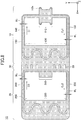
- FIG. 1 is a schematic plan view illustrating an example of the loop heat pipe in the first embodiment.
- a loop heat pipe 1 includes a first loop heat pipe 10, a second loop heat pipe 20, and a connecting part 30.
- the first loop heat pipe 10 includes an evaporator 110, a condenser 120, a vapor pipe 130, and a liquid pipe 140.
- the evaporator 110 has a function to vaporize a working fluid C1 and generate vapor Cv1.
- the evaporator 110 accommodates therein a wick (not illustrated), for example.
- the wick is a porous sintered metal or sintered resin, and the working fluid C1 in a liquid phase preferably permeates the wick in a vicinity of the liquid pipe 140.
- a capillary force of the wick acts on the working fluid C1 in the liquid phase, and the capillary force counters the vapor Cv1 of the working fluid C1, to cause the working fluid C1 in the liquid phase to function as a backflow valve that prevents a backflow of the vapor Cv1 from the vapor pipe 130 to the liquid pipe 140.
- the condenser 120 has a function to liquefy the vapor Cv1 of the working fluid C1.
- the evaporator 110 and the condenser 120 are connected via the vapor pipe 130 and the liquid pipe 140, and the vapor pipe 130 and the liquid pipe 140 form a loop-shaped passage (or channel) 150 in which the working liquid C1 or the vapor Cv1 flows.
- a width W 1 of the vapor pipe 130 may be approximately 8 mm, for example.
- a width W 2 of the liquid pipe 140 may be approximately 6 mm, for example.
- FIG. 2 is a cross sectional view of an evaporator and its periphery of the loop heat pipe in the first embodiment.
- the evaporator 110 includes four penetration holes 110x, for example.
- a bolt 440 is inserted into each penetration hole 110x of the evaporator 110 and a corresponding penetration hole 500x formed in a circuit board (or substrate) 500, and a tip of each bolt 550 is fastened by a nut 560 at a lower surface of the circuit board 500 in FIG. 2 , to fix the evaporator 110 on the circuit board 500.
- a heat generating component 520 which is an electronic component such as a CPU or the like, for example, is a heat generating part.
- the heat generating component 520 is mounted on the circuit board 500 via bumps 510.
- An upper surface of the heat generating component 520 makes contact with a lower surface of the evaporator 110.
- the working fluid C1 inside the evaporator 110 is vaporized by the heat generated from the heat generating component 520, to generate the vapor Cv1.
- the second loop heat pipe 20 includes an evaporator 210, a condenser 220, a vapor pipe 230, and a liquid pipe 240.
- the evaporator 210 has a function to vaporize a working fluid C2 and generate vapor Cv2.
- the evaporator 210 accommodates therein a wick (not illustrated), for example.
- the wick is a porous sintered metal or sintered resin, and the working fluid C2 in a liquid phase preferably permeates the wick in a vicinity of the liquid pipe 240.
- a capillary force of the wick acts on the working fluid C2 in the liquid phase, and the capillary force counters the vapor Cv2 of the working fluid C1, to cause the working fluid C2 in the liquid phase to function as a backflow valve that prevents a backflow of the vapor Cv2 from the vapor pipe 230 to the liquid pipe 240.
- the condenser 220 has a function to liquefy the vapor Cv2 of the working fluid C2.
- the evaporator 210 and the condenser 220 are connected via the vapor pipe 230 and the liquid pipe 240, and the vapor pipe 230 and the liquid pipe 240 form a loop-shaped passage (or channel) 250 in which the working liquid C2 or the vapor Cv2 flows.
- a width W 3 of the vapor pipe 230 may be approximately 8 mm, for example.
- a width W 4 of the liquid pipe 240 may be approximately 6 mm, for example.
- the shape of the first loop heat pipe 10 and the shape of the second loop heat pipe 20 do not necessarily have to be the same.
- the condenser 120 of the first loop heat pipe 10 and at least the evaporator 210 of the second loop heat pipe 20 are connected by the connecting part 30.
- the evaporator 210, a part of the vapor pipe 230, a part of the liquid pipe 240, and the condenser 120 are connected by the connecting part 30.
- the first loop heat pipe 10, the second loop heat pipe 20, and the connecting part 30 are integrally formed by a metal. Because the first loop heat pipe 10, the second loop heat pipe 20, and the connecting part 30 are integrally formed, a boundary between the condenser 120 of the first loop heat pipe 10 and the connecting part 30, and a boundary between the connecting part 30 and the evaporator 210 of the second loop heat pipe 20 do not need to be clearly distinguished.
- the working fluid C1 is not limited to a particular type of fluid. From a viewpoint of efficiently cooling the heat generating component 520 by latent heat of vaporization, a liquid with a high vapor pressure and a large latent heat of vaporization is preferably used as the working fluid C1. Examples of such a liquid, preferably used as the working fluid C1, include ammonia, water, fluorocarbon, alcohol, and acetone, for example.
- the vapor Cv1 generated from the evaporator 110 passes through the vapor pipe 130 and is guided to the condenser 120, to be liquefied by the condenser 120.
- the heat generated from the heat generating component 520 is transferred to the condenser 120, to reduce a temperature rise of the heat generating component 520.
- the working fluid C1, liquefied by the condenser 120 passes through the liquid pipe 140 and is guided to the evaporator 110.
- the working fluid C2 is selected to a liquid with a saturated vapor pressure that is lower than that of the working fluid C1.
- the working fluid C2 is not limited to a particular type of fluid. In a case in which water is used as the working fluid C1, ethanol with a saturated vapor pressure lower than that of water, may be used as the working fluid C2.
- the heat transferred to the condenser 120 of the first loop heat pipe 10 is transferred to the evaporator 210 of the second loop heat pipe 20, via the connecting part 30. Due to the heat transferred to the evaporator 210, the vapor Cv2 is generated from the working fluid C2 within the evaporator 210. The vapor Cv2 passes through the vapor pipe 230 and is guided to the condenser 220, to be liquefied by the condenser 220.
- a temperature T1 of the evaporator 110, a temperature T2 of the condenser 120, a temperature T3 of the evaporator 210, and a temperature T4 of the condenser 220 satisfy a relationship T1 > T2 > T3 > T4.
- the working fluid C2 is selected to the liquid with the saturated vapor pressure that is lower than that of the working fluid C1, in order to operate the second loop heat pipe 20.
- the working fluid C2 is not limited to such a liquid, and other methods may be used to operate the second loop heat pipe 20.
- the same fluid or the same type of fluid may be used as the working fluid C1 and the working fluid C2, and a pressure reducing value within the passage 250 of the second loop heat pipe 20 may be set smaller than that within the passage 150 of the first loop heat pipe 10. In this case, it is also possible to operate the second loop heat pipe 20.
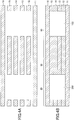
- FIG. 3 is a cross sectional view along a line A-A in FIG. 1 .
- the evaporator 110, the condenser 120, the vapor pipe 130, and the liquid pipe 140 of the first loop heat pipe 10 the evaporator 210, the condenser 220, the vapor pipe 230, and the liquid pipe 240 of the second loop heat pipe 20, and the connecting part 30 form an integral structure that is formed by successively stacking six metal layers 11, 12, 13, 14, 15, and 16.
- the number of metal layers that are stacked is not limited to six, and the integral structure may be formed by stacking at least three or more metal layers.
- the metal layers 11 through 16 are copper layers having a high thermal conductivity, for example, and the metal layers 11 through 16 are directly bonded to each other by solid-phase welding or the like. Each of the metal layers 11 through 16 has a thickness of approximately 50 ⁇ m to approximately 200 ⁇ m, for example.
- the metal layers 11 through 16 are not limited to the copper layers, and may be other metal layers including stainless steel layers, aluminum layers, magnesium alloy layers, or the like, for example.
- the metal layers 11 and 16 are outermost metal layers located on both outer sides of a stacked structure that is formed by the metal layers 11 through 16, and form a part of outer walls of the passages 150 and 250.
- the metal layers 12 through 15 are intermediate metal layers that are sandwiched between the metal layers 11 and 16 that are the outermost metal layers.
- An intermediate layer structure is formed by the metal layers 12 through 15 in this example, however, the intermediate layer structure may be formed by at least one metal layer.
- the passage 150 of the first loop heat pipe 10 and the passage 250 of the second loop heat pipe 20 are separate and independent from each other, and are not connected to each other. In other words, no hollow or cavity part, that may form a passage or the like, is formed in the connecting part 30.
- FIG. 4A and FIG. 4B are diagrams illustrating an example of manufacturing stages of the loop heat pipe in the first embodiment.
- FIG. 4A and FIG. 4B illustrate cross sections corresponding to the cross section illustrated in FIG. 3 .
- metal sheets are prepared. Two of the six metal sheets are formed to the external shape illustrated in FIG. 1 , to form the metal layers 11 and 16. In addition, the remaining four metal sheets are formed to the external shape illustrated in FIG. 1 , and holes that become the passages 150 and 250 or the like are formed, to form the metal layers 12 through 15.
- the metal sheets may be formed by processes such as pressing, etching, or the like. In a case in which the material used for the metal sheet is copper, the etching may use a ferric chloride solution.
- the metal layers 11 through 16 are stacked. More particularly, the metal layers 11 and 16 form the outermost metal layers of the stacked structure.
- the metal layers 12 through 15, forming the intermediate metal layers, are stacked between the metal layers 11 and 16, forming the outermost metal layers.
- the stacked structure that is formed by the metal layers 11 through 16 is subjected to pressing, heating, and solid-phase welding. As a result, the adjacent metal layers are directly bonded to each other, to thereby complete the loop heat pipe 1 including the first loop heat pipe 10, the second loop heat pipe 20, and the connecting part 30.
- the solid-phase welding refers to a method of bonding two parts, that are to be connected, in the solid-phase (or solid state), without melting the two parts. More particularly, the solid-phase welding heats the two parts in the solid-phase to soften the two parts, and further, applies pressure on the two parts to cause plastic deformation to bond the two parts to each other. In order to satisfactorily bond the adjacent metal layers to each other by the solid-phase welding, all of the metal layers 11 through 16 are preferably made of the same material.
- the method of manufacturing the loop heat pipe 1 described above can form the structure before the loop heat pipe 1 is bent.
- the loop heat pipe 1 can thereafter be bent at an arbitrary angle at the connecting part 30, by applying a mechanical force on the structure.
- the first loop heat pipe 10 and the second loop heat pipe 20 can be bent relative to each other at the connecting part 30 of the loop heat pipe 1, so that the evaporator 110 and the condenser 220 are not positioned on the same plane.
- the bending may be performed at a timing immediately after the planar-shaped loop heat pipe 1 illustrated in FIG. 1 is formed, or at an arbitrary timing before the loop heat pipe 1 is used, such as before mounting the loop heat pipe 1 on the heat generating component 520, a housing, or the like.
- FIG. 5A and FIG. 5B are side views illustrating a state in which the loop heat pipe in the first embodiment is bent and mounted on the housing or the like, and illustration of detailed parts is omitted for the sake of convenience.
- FIG. 5A illustrates an example in which the loop heat pipe 1 is bent approximately 90 degrees at the connecting part 30.
- the evaporator 110 of the first loop heat pipe 10 is mounted on the heat generating component 520 that is mounted on the circuit board 500.
- the condenser 220 of the second loop heat pipe 20 is mounted on a housing 590 that holds the circuit board 500.
- the housing 590 is a heat sink part that is made of a metal or the like.
- FIG. 5B illustrates an example in which the loop heat pipe 1 is bent approximately 180 degrees at the connecting part 30.
- the evaporator 110 of the first loop heat pipe 10 is mounted on the heat generating component 520 that is mounted on the circuit board 500, similarly to the example illustrated in FIG. 5A .
- the condenser 220 of the second loop heat pipe 20 is mounted on the housing 590 that holds the circuit board 500, similarly to the example illustrated in FIG. 5B .
- the loop heat pipe 1 can be bent by an appropriate angle at the connecting part 30 connecting the first loop heat pipe 10 and the second loop heat pipe 20, according to an arrangement of the electronic component, such as the heat generating component 520, that becomes the heat generating part, and the housing 590 that becomes the heat sink part. Accordingly, in the product in which the heat generating part and the heat sink part do not exist on the same plane, it is possible to easily transfer the heat from the heat generating part to the heat sink part.
- a width of the connecting part 30 along a X-direction in FIG. 1 may be arbitrarily set according to the bending angle at the connecting part 30. For example, when bending angle at the connecting part 30 is approximately 90 degrees as illustrated in FIG. 5A , the width of the connecting part 30 may be relatively narrow. When the bending angle at the connecting part 30 is approximately 180 degrees as illustrated in FIG.
- the width of the connecting part 30 needs to be relatively wide because the bending occurs at two locations.
- the width of the connecting part 30 needs to be changed according to a distance of mutually opposing parts of the first loop heat pipe 10 and the second loop heat pipe 20.
- the loop heat pipe 1 may be bent to shapes other than the shapes illustrated in FIG. 5A and FIG. 5B .
- first through third modifications of the first embodiment the shape of the connecting part is different from that of the first embodiment.
- those parts that are the same are designated by the same reference numerals, and a repeated description of the same parts may be omitted.
- FIG. 6 is a schematic plan view illustrating an example of the loop heat pipe in the first modification of the first embodiment.
- a loop heat pipe 1A illustrated in FIG. 6 differs from the loop heat pipe 1 illustrated in FIG. 1 , in that the connecting part 30 of the loop heat pipe 1 is replaced by a connecting part 30A.
- a length of the connecting part 30 along a Y-direction in FIG. 1 is approximately the same as the lengths of the first loop heat pipe 10 and the second loop heat pipe 20.
- the length of the connecting part 30A along the Y-direction in FIG. 6 is shorter than the lengths of the first loop heat pipe 10 and the second loop heat pipe 20.
- the connecting part 30 connects a vicinity of a center part along the Y-direction of the condenser 120 of the first loop heat pipe 10, and the evaporator 210 of the second loop heat pipe 20.
- the connecting part only needs to connect at least a part of the condenser 120 of the first loop heat pipe 10 and the evaporator 210 of the second loop heat pipe 20. Further, the length of the connecting part along the Y-direction may be appropriately determined by taking into consideration the strength, ease of bending, or the like of the entire loop heat pipe 1.
- FIG. 7 is a schematic plan view illustrating an example of the loop heat pipe in the second modification of the first embodiment.
- a loop heat pipe 1B illustrated in FIG. 7 differs from the loop heat pipe 1A illustrated in FIG. 6 , in that a thermal insulating member 40 is additionally provided.
- the thermal insulating member 40 covers surfaces of the connecting part 30A. More particularly, the thermal insulating member 30 covers a top surface, a bottom surface, and a pair of side surfaces opposing each other along the Y-direction. For example, the thermal insulating member 40 is adhered on the surfaces of the connecting part 30A.
- the thermal insulating member 40 may be made of an appropriate material capable of reducing heat release from the connecting part 30A.
- a metal material such as aluminum or the like, may be used for the thermal insulating member 40.
- a foam material such as urethane, polystyrene, or the like, may be used for the thermal insulating member 40.
- a fiber material such as glass wool, rock wool, or the like, may be used for the thermal insulating member 40.
- the thermal insulating member may be provided at parts other than the connecting part.
- the thermal insulating member may be provided to cover the entire surface of the first loop heat pipe 10 and the second loop heat pipe 20, excluding the evaporators 110 and 210 and the condensers 120 and 220.
- FIG. 8 is a schematic plan view illustrating an example of the loop heat pipe in the third modification of the first embodiment.
- a loop heat pipe 1C illustrated in FIG. 8 differs from the loop heat pipe 1 illustrated in FIG. 1 , in that slits 50 are additionally provided.
- the slits 50 are discretely provided in the connecting part 30, at parts excluding the center part of the connecting part 30 along the Y-direction.
- the center part of the connecting part 30 along the Y-direction makes contact with the evaporator 210.
- a planar shape of each slit 50 may be an arbitrary shape including a rectangular shape, a circular shape, an oval shape, a polygonal shape, or the like.
- the connecting part By providing the slits at predetermined positions of the connecting part, it is possible to increase the length of the connecting part along the Y-direction and secure a sufficient strength of the connecting part. In addition, it is possible to prevent the heat release from the connecting part due to radiation. As a result, it is possible to reduce deterioration in the function of transferring the heat from the first loop heat pipe 10 to the second loop heat pipe 20.
- the embodiments and the modifications may be appropriately combined.
- the surfaces of the connecting part 30 may be covered by the thermal insulating member 40 in each of the loop heat pipe 1 illustrated in FIG. 1 and the loop heat pipe 1C illustrated in FIG. 8 .
Description
- The invention relates to a loop heat pipe and a method of manufacturing the loop heat pipe. A loop heat pipe according to the preamble of
claim 1 is known from documentJP 2001 27321 A - The heat pipe is a known device for cooling a heat generating component, such as a CPU (Central Processing Unit) or the like, mounted in an electronic apparatus. The heat pipe is a device that transfers heat by utilizing a phase change of a working fluid.
- A loop heat pipe is an example of the heat pipe, and includes an evaporator that vaporizes the working fluid, and a condenser that liquefies the vaporized working fluid. The evaporator and the condenser are connected via a liquid pipe and a vapor pipe that form a loop-shaped passage (or channel). In the loop heat pipe, the working fluid flows through the loop-shaped passage in one direction. The evaporator and the condenser of the loop heat pipe are formed on the same plane, as described in International Publication No.
WO2015/087451A1 , for example. - However, in an actual product, a heat generating part and a heat sink part do not necessary exist on the same substrate (that is, on the same plane). When providing the loop heat pipe in the product in which the heat generating part and the heat sink do not exist on the same substrate, the vapor pipe and the liquid pipe need to be bent in order to mount the evaporator on the heat generating part and to mount the heat sink part on the condenser. However, when the hollow pipe is bent, an inner side of the pipe shrinks, while an outer side of the pipe stretches. For this reason, an inside of the bent part of the pipe becomes constricted and prevents a smooth flow of the working fluid, to make it difficult to transfer the heat from the heat generating part to the heat sink part.
- Accordingly, it is an object in one aspect of the embodiments to provide a loop heat pipe and a method of manufacturing the loop heat pipe, which can easily transfer the heat from the heat generating part to the heat sink part, even in a case in which the heat generating part and the heat sink part do not exist on the same plane.
- This problem is solved by a loop heat pipe and a method of manufacturing a loop heat pipe according to
claims - The object and advantages of the embodiments will be realized and attained by means of the elements and combinations particularly pointed out in the claims.
- It is to be understood that both the foregoing general description and the following detailed description are exemplary and explanatory and not restrictive of the invention, as claimed.
-
-
FIG. 1 is a schematic plan view illustrating an example of a loop heat pipe in a first embodiment; -
FIG. 2 is a cross sectional view of an evaporator and its periphery of the loop heat pipe in the first embodiment; -
FIG. 3 is a cross sectional view along a line A-A inFIG. 1 ; -
FIG. 4A and FIG. 4B are diagrams illustrating an example of manufacturing stages of the loop heat pipe in the first embodiment; -
FIG. 5A and FIG. 5B are side views illustrating a state in which the loop heat pipe in the first embodiment is bent and mounted on a housing or the like; -
FIG. 6 is a schematic plan view illustrating an example of the loop heat pipe in a first modification of the first embodiment; -
FIG. 7 is a schematic plan view illustrating an example of the loop heat pipe in a second modification of the first embodiment; and -
FIG. 8 is a schematic plan view illustrating an example of the loop heat pipe in a third modification of the first embodiment. - Preferred embodiments of the present invention will be described with reference to the accompanying drawings. In the drawings, those parts that are the same are designated by the same reference numerals, and a repeated description of the same parts may be omitted.
- A description will now be given of embodiments and modifications of the loop heat pipe and the method of manufacturing the loop heat pipe according to the present invention.
- First, a structure of the loop heat pipe in a first embodiment will be described.
FIG. 1 is a schematic plan view illustrating an example of the loop heat pipe in the first embodiment. - As illustrated in
FIG. 1 , aloop heat pipe 1 includes a firstloop heat pipe 10, a secondloop heat pipe 20, and a connectingpart 30. - The first
loop heat pipe 10 includes anevaporator 110, acondenser 120, avapor pipe 130, and aliquid pipe 140. In the firstloop heat pipe 10, theevaporator 110 has a function to vaporize a working fluid C1 and generate vapor Cv1. Theevaporator 110 accommodates therein a wick (not illustrated), for example. The wick is a porous sintered metal or sintered resin, and the working fluid C1 in a liquid phase preferably permeates the wick in a vicinity of theliquid pipe 140. Hence, a capillary force of the wick acts on the working fluid C1 in the liquid phase, and the capillary force counters the vapor Cv1 of the working fluid C1, to cause the working fluid C1 in the liquid phase to function as a backflow valve that prevents a backflow of the vapor Cv1 from thevapor pipe 130 to theliquid pipe 140. - The
condenser 120 has a function to liquefy the vapor Cv1 of the working fluid C1. Theevaporator 110 and thecondenser 120 are connected via thevapor pipe 130 and theliquid pipe 140, and thevapor pipe 130 and theliquid pipe 140 form a loop-shaped passage (or channel) 150 in which the working liquid C1 or the vapor Cv1 flows. A width W1 of thevapor pipe 130 may be approximately 8 mm, for example. In addition, a width W2 of theliquid pipe 140 may be approximately 6 mm, for example. -
FIG. 2 is a cross sectional view of an evaporator and its periphery of the loop heat pipe in the first embodiment. As illustrated inFIG. 1 andFIG. 2 , theevaporator 110 includes fourpenetration holes 110x, for example. A bolt 440 is inserted into eachpenetration hole 110x of theevaporator 110 and acorresponding penetration hole 500x formed in a circuit board (or substrate) 500, and a tip of eachbolt 550 is fastened by anut 560 at a lower surface of thecircuit board 500 inFIG. 2 , to fix theevaporator 110 on thecircuit board 500. - A
heat generating component 520, which is an electronic component such as a CPU or the like, for example, is a heat generating part. Theheat generating component 520 is mounted on thecircuit board 500 viabumps 510. An upper surface of theheat generating component 520 makes contact with a lower surface of theevaporator 110. The working fluid C1 inside theevaporator 110 is vaporized by the heat generated from theheat generating component 520, to generate the vapor Cv1. - Returning now to the description of
FIG. 1 , the secondloop heat pipe 20 includes anevaporator 210, acondenser 220, avapor pipe 230, and aliquid pipe 240. In the secondloop heat pipe 20, theevaporator 210 has a function to vaporize a working fluid C2 and generate vapor Cv2. Theevaporator 210 accommodates therein a wick (not illustrated), for example. The wick is a porous sintered metal or sintered resin, and the working fluid C2 in a liquid phase preferably permeates the wick in a vicinity of theliquid pipe 240. Hence, a capillary force of the wick acts on the working fluid C2 in the liquid phase, and the capillary force counters the vapor Cv2 of the working fluid C1, to cause the working fluid C2 in the liquid phase to function as a backflow valve that prevents a backflow of the vapor Cv2 from thevapor pipe 230 to theliquid pipe 240. - The
condenser 220 has a function to liquefy the vapor Cv2 of the working fluid C2. Theevaporator 210 and thecondenser 220 are connected via thevapor pipe 230 and theliquid pipe 240, and thevapor pipe 230 and theliquid pipe 240 form a loop-shaped passage (or channel) 250 in which the working liquid C2 or the vapor Cv2 flows. A width W3 of thevapor pipe 230 may be approximately 8 mm, for example. In addition, a width W4 of theliquid pipe 240 may be approximately 6 mm, for example. - The shape of the first
loop heat pipe 10 and the shape of the secondloop heat pipe 20 do not necessarily have to be the same. - The
condenser 120 of the firstloop heat pipe 10 and at least theevaporator 210 of the secondloop heat pipe 20 are connected by the connectingpart 30. In the example illustrated inFIG. 1 , theevaporator 210, a part of thevapor pipe 230, a part of theliquid pipe 240, and thecondenser 120 are connected by the connectingpart 30. - The first
loop heat pipe 10, the secondloop heat pipe 20, and the connectingpart 30 are integrally formed by a metal. Because the firstloop heat pipe 10, the secondloop heat pipe 20, and the connectingpart 30 are integrally formed, a boundary between thecondenser 120 of the firstloop heat pipe 10 and the connectingpart 30, and a boundary between the connectingpart 30 and theevaporator 210 of the secondloop heat pipe 20 do not need to be clearly distinguished. - In the first
loop heat pipe 10, the working fluid C1 is not limited to a particular type of fluid. From a viewpoint of efficiently cooling theheat generating component 520 by latent heat of vaporization, a liquid with a high vapor pressure and a large latent heat of vaporization is preferably used as the working fluid C1. Examples of such a liquid, preferably used as the working fluid C1, include ammonia, water, fluorocarbon, alcohol, and acetone, for example. - The vapor Cv1 generated from the evaporator 110 passes through the
vapor pipe 130 and is guided to thecondenser 120, to be liquefied by thecondenser 120. Hence, the heat generated from theheat generating component 520 is transferred to thecondenser 120, to reduce a temperature rise of theheat generating component 520. The working fluid C1, liquefied by thecondenser 120, passes through theliquid pipe 140 and is guided to theevaporator 110. - In the second
loop heat pipe 20, the working fluid C2 is selected to a liquid with a saturated vapor pressure that is lower than that of the working fluid C1. The working fluid C2 is not limited to a particular type of fluid. In a case in which water is used as the working fluid C1, ethanol with a saturated vapor pressure lower than that of water, may be used as the working fluid C2. - The heat transferred to the
condenser 120 of the firstloop heat pipe 10 is transferred to theevaporator 210 of the secondloop heat pipe 20, via the connectingpart 30. Due to the heat transferred to theevaporator 210, the vapor Cv2 is generated from the working fluid C2 within theevaporator 210. The vapor Cv2 passes through thevapor pipe 230 and is guided to thecondenser 220, to be liquefied by thecondenser 220. A temperature T1 of theevaporator 110, a temperature T2 of thecondenser 120, a temperature T3 of theevaporator 210, and a temperature T4 of thecondenser 220 satisfy a relationship T1 > T2 > T3 > T4. - In the example described above, the working fluid C2 is selected to the liquid with the saturated vapor pressure that is lower than that of the working fluid C1, in order to operate the second
loop heat pipe 20. However, the working fluid C2 is not limited to such a liquid, and other methods may be used to operate the secondloop heat pipe 20. For example, the same fluid or the same type of fluid may be used as the working fluid C1 and the working fluid C2, and a pressure reducing value within thepassage 250 of the secondloop heat pipe 20 may be set smaller than that within thepassage 150 of the firstloop heat pipe 10. In this case, it is also possible to operate the secondloop heat pipe 20. -
FIG. 3 is a cross sectional view along a line A-A inFIG. 1 . As illustrated inFIG. 3 , theevaporator 110, thecondenser 120, thevapor pipe 130, and theliquid pipe 140 of the firstloop heat pipe 10, theevaporator 210, thecondenser 220, thevapor pipe 230, and theliquid pipe 240 of the secondloop heat pipe 20, and the connectingpart 30 form an integral structure that is formed by successively stacking sixmetal layers - The metal layers 11 through 16 are copper layers having a high thermal conductivity, for example, and the metal layers 11 through 16 are directly bonded to each other by solid-phase welding or the like. Each of the metal layers 11 through 16 has a thickness of approximately 50 µm to approximately 200 µm, for example. Of course, the metal layers 11 through 16 are not limited to the copper layers, and may be other metal layers including stainless steel layers, aluminum layers, magnesium alloy layers, or the like, for example.
- The metal layers 11 and 16 are outermost metal layers located on both outer sides of a stacked structure that is formed by the metal layers 11 through 16, and form a part of outer walls of the
passages - The
passage 150 of the firstloop heat pipe 10 and thepassage 250 of the secondloop heat pipe 20 are separate and independent from each other, and are not connected to each other. In other words, no hollow or cavity part, that may form a passage or the like, is formed in the connectingpart 30. - Next, a method of manufacturing the loop heat pipe in the first embodiment will be described.
FIG. 4A and FIG. 4B are diagrams illustrating an example of manufacturing stages of the loop heat pipe in the first embodiment.FIG. 4A and FIG. 4B illustrate cross sections corresponding to the cross section illustrated inFIG. 3 . - First, in the manufacturing stage illustrated in
FIG. 4A , six metal sheets are prepared. Two of the six metal sheets are formed to the external shape illustrated inFIG. 1 , to form the metal layers 11 and 16. In addition, the remaining four metal sheets are formed to the external shape illustrated inFIG. 1 , and holes that become thepassages - Next, in the manufacturing stage illustrated in
FIG. 4B , the metal layers 11 through 16 are stacked. More particularly, the metal layers 11 and 16 form the outermost metal layers of the stacked structure. The metal layers 12 through 15, forming the intermediate metal layers, are stacked between the metal layers 11 and 16, forming the outermost metal layers. The stacked structure that is formed by the metal layers 11 through 16 is subjected to pressing, heating, and solid-phase welding. As a result, the adjacent metal layers are directly bonded to each other, to thereby complete theloop heat pipe 1 including the firstloop heat pipe 10, the secondloop heat pipe 20, and the connectingpart 30. Thereafter, insides of theliquid pipes liquid pipe 140 through an injection opening (not illustrated), and the working fluid C2 is injected into theliquid pipe 240 through an injection opening (not illustrated). After injecting the working fluids C1 and C2, the respective injection openings are sealed. - The solid-phase welding refers to a method of bonding two parts, that are to be connected, in the solid-phase (or solid state), without melting the two parts. More particularly, the solid-phase welding heats the two parts in the solid-phase to soften the two parts, and further, applies pressure on the two parts to cause plastic deformation to bond the two parts to each other. In order to satisfactorily bond the adjacent metal layers to each other by the solid-phase welding, all of the metal layers 11 through 16 are preferably made of the same material.
- The method of manufacturing the
loop heat pipe 1 described above can form the structure before theloop heat pipe 1 is bent. Theloop heat pipe 1 can thereafter be bent at an arbitrary angle at the connectingpart 30, by applying a mechanical force on the structure. In other words, the firstloop heat pipe 10 and the secondloop heat pipe 20 can be bent relative to each other at the connectingpart 30 of theloop heat pipe 1, so that theevaporator 110 and thecondenser 220 are not positioned on the same plane. The bending may be performed at a timing immediately after the planar-shapedloop heat pipe 1 illustrated inFIG. 1 is formed, or at an arbitrary timing before theloop heat pipe 1 is used, such as before mounting theloop heat pipe 1 on theheat generating component 520, a housing, or the like. -
FIG. 5A and FIG. 5B are side views illustrating a state in which the loop heat pipe in the first embodiment is bent and mounted on the housing or the like, and illustration of detailed parts is omitted for the sake of convenience.FIG. 5A illustrates an example in which theloop heat pipe 1 is bent approximately 90 degrees at the connectingpart 30. InFIG. 5A , theevaporator 110 of the firstloop heat pipe 10 is mounted on theheat generating component 520 that is mounted on thecircuit board 500. In addition, thecondenser 220 of the secondloop heat pipe 20 is mounted on ahousing 590 that holds thecircuit board 500. Thehousing 590 is a heat sink part that is made of a metal or the like. -
FIG. 5B illustrates an example in which theloop heat pipe 1 is bent approximately 180 degrees at the connectingpart 30. InFIG. 5B , theevaporator 110 of the firstloop heat pipe 10 is mounted on theheat generating component 520 that is mounted on thecircuit board 500, similarly to the example illustrated inFIG. 5A . In addition, thecondenser 220 of the secondloop heat pipe 20 is mounted on thehousing 590 that holds thecircuit board 500, similarly to the example illustrated inFIG. 5B . - Hence, the
loop heat pipe 1 can be bent by an appropriate angle at the connectingpart 30 connecting the firstloop heat pipe 10 and the secondloop heat pipe 20, according to an arrangement of the electronic component, such as theheat generating component 520, that becomes the heat generating part, and thehousing 590 that becomes the heat sink part. Accordingly, in the product in which the heat generating part and the heat sink part do not exist on the same plane, it is possible to easily transfer the heat from the heat generating part to the heat sink part. - In addition, because the connecting
part 30 does not include a hollow or cavity part that may form a passage or the like, the fluid flow will not be affected by the bending of theloop heat pipe 1 at the connectingpart 30. Consequently, the transfer of heat will not be interfered by the bending of theloop heat pipe 1 at the connectingpart 30. A width of the connectingpart 30 along a X-direction inFIG. 1 may be arbitrarily set according to the bending angle at the connectingpart 30. For example, when bending angle at the connectingpart 30 is approximately 90 degrees as illustrated inFIG. 5A , the width of the connectingpart 30 may be relatively narrow. When the bending angle at the connectingpart 30 is approximately 180 degrees as illustrated inFIG. 5B , the width of the connectingpart 30 needs to be relatively wide because the bending occurs at two locations. In addition, when the bending angle at the connectingpart 30 is approximately 180 degrees as illustrated inFIG. 5B , the width of the connectingpart 30 needs to be changed according to a distance of mutually opposing parts of the firstloop heat pipe 10 and the secondloop heat pipe 20. - The
loop heat pipe 1 may be bent to shapes other than the shapes illustrated inFIG. 5A and FIG. 5B . - In each of first through third modifications of the first embodiment, the shape of the connecting part is different from that of the first embodiment. In the first through third modifications of the first embodiment, those parts that are the same are designated by the same reference numerals, and a repeated description of the same parts may be omitted.
-
FIG. 6 is a schematic plan view illustrating an example of the loop heat pipe in the first modification of the first embodiment. Aloop heat pipe 1A illustrated inFIG. 6 differs from theloop heat pipe 1 illustrated inFIG. 1 , in that the connectingpart 30 of theloop heat pipe 1 is replaced by a connectingpart 30A. - A length of the connecting
part 30 along a Y-direction inFIG. 1 is approximately the same as the lengths of the firstloop heat pipe 10 and the secondloop heat pipe 20. On the other hand, the length of the connectingpart 30A along the Y-direction inFIG. 6 is shorter than the lengths of the firstloop heat pipe 10 and the secondloop heat pipe 20. In addition, the connectingpart 30 connects a vicinity of a center part along the Y-direction of thecondenser 120 of the firstloop heat pipe 10, and theevaporator 210 of the secondloop heat pipe 20. - In other words, the connecting part only needs to connect at least a part of the
condenser 120 of the firstloop heat pipe 10 and theevaporator 210 of the secondloop heat pipe 20. Further, the length of the connecting part along the Y-direction may be appropriately determined by taking into consideration the strength, ease of bending, or the like of the entireloop heat pipe 1. -
FIG. 7 is a schematic plan view illustrating an example of the loop heat pipe in the second modification of the first embodiment. Aloop heat pipe 1B illustrated inFIG. 7 differs from theloop heat pipe 1A illustrated inFIG. 6 , in that a thermal insulatingmember 40 is additionally provided. - The thermal insulating
member 40 covers surfaces of the connectingpart 30A. More particularly, the thermal insulatingmember 30 covers a top surface, a bottom surface, and a pair of side surfaces opposing each other along the Y-direction. For example, the thermal insulatingmember 40 is adhered on the surfaces of the connectingpart 30A. The thermal insulatingmember 40 may be made of an appropriate material capable of reducing heat release from the connectingpart 30A. For example, a metal material, such as aluminum or the like, may be used for the thermal insulatingmember 40. In addition, a foam material, such as urethane, polystyrene, or the like, may be used for the thermal insulatingmember 40. Further, a fiber material, such as glass wool, rock wool, or the like, may be used for the thermal insulatingmember 40. - In other words, by covering the surfaces of the connecting member by the thermal insulating member, it is possible to prevent heat release from the connecting part due to radiation. As a result, it is possible to reduce deterioration in the function of transferring the heat from the first
loop heat pipe 10 to the secondloop heat pipe 20. - The thermal insulating member may be provided at parts other than the connecting part. For example, the thermal insulating member may be provided to cover the entire surface of the first
loop heat pipe 10 and the secondloop heat pipe 20, excluding theevaporators condensers -
FIG. 8 is a schematic plan view illustrating an example of the loop heat pipe in the third modification of the first embodiment. Aloop heat pipe 1C illustrated inFIG. 8 differs from theloop heat pipe 1 illustrated inFIG. 1 , in that slits 50 are additionally provided. - The
slits 50 are discretely provided in the connectingpart 30, at parts excluding the center part of the connectingpart 30 along the Y-direction. The center part of the connectingpart 30 along the Y-direction makes contact with theevaporator 210. A planar shape of each slit 50 may be an arbitrary shape including a rectangular shape, a circular shape, an oval shape, a polygonal shape, or the like. - By providing the slits at predetermined positions of the connecting part, it is possible to increase the length of the connecting part along the Y-direction and secure a sufficient strength of the connecting part. In addition, it is possible to prevent the heat release from the connecting part due to radiation. As a result, it is possible to reduce deterioration in the function of transferring the heat from the first
loop heat pipe 10 to the secondloop heat pipe 20. - Although the embodiments and the modifications are numbered with, for example, "first," "second," or "third," the ordinal numbers do not imply priorities of the embodiments. Many other variations and modifications will be apparent to those skilled in the art.
- For example, the embodiments and the modifications may be appropriately combined. As an example, the surfaces of the connecting
part 30 may be covered by the thermal insulatingmember 40 in each of theloop heat pipe 1 illustrated inFIG. 1 and theloop heat pipe 1C illustrated inFIG. 8 . - According to the embodiments and the modifications, it is possible to easily transfer the heat from the heat generating part to the heat sink part, even in a case in which the heat generating part and the heat sink part do not exist on the same plane.
- The description above use terms such as "determine", or the like to describe the embodiments, however, such terms are abstractions of the actual operations that are performed. Hence, the actual operations that correspond to such terms may vary depending on the implementation, as is obvious to those skilled in the art.
Claims (16)
- A loop heat pipe (1, 1A, 1B, 1C) comprising:a first loop heat pipe (10) includinga first evaporator (110) configured to vaporize a first working fluid into vapor,a first condenser (120) configured to liquefy the vapor of the first working fluid,a first liquid pipe (140) configured to connect the first evaporator and the first condenser, anda first vapor pipe (130) configured to connect the first evaporator and the first condenser, and to form a first loop together with the first liquid pipe;a second loop heat pipe (20) includinga second evaporator (210) configured to vaporize a second working fluid into vapor,a second condenser (220) configured to liquefy the vapor of the second working fluid,a second liquid pipe (240) configured to connect the second evaporator and the second condenser, anda second vapor pipe (230) configured to connect the second evaporator and the second condenser, and to form a second loop together with the second liquid pipe;
wherein the first loop and the second loop are separate and independent from each other;
characterized in that the loop heat pipe further comprises a connecting part (30, 30A) connecting the first condenser of the first loop heat pipe (10) and the second evaporator of the second loop heat pipe (20), said connecting part being configured to transfer heat from the first condenser (120) of the first loop heat pipe (10) to the second evaporator (210) of the second loop heat pipe (20), andwherein the first loop heat pipe, the second loop heat pipe, and the connecting part are integrally formed by a metal. - The loop heat pipe (1, 1A, 1B, 1C) as claimed in claim 1, characterized in that the first loop heat pipe (10), the second loop heat pipe (20), and the connecting part (30, 30A) are formed by stacking a plurality of metal layers.
- The loop heat pipe (1, 1A, 1B, 1C) as claimed in claim 1 or 2, characterized in that the second working fluid is a liquid with a saturated vapor pressure that is lower than that of the first working fluid.
- The loop heat pipe (1, 1A, 1B, 1C) as claimed in claim 1 or 2, characterized in that
a same fluid is used as the first working fluid and the second working fluid, and
a pressure reducing value within the second loop is smaller than that within the first loop. - The loop heat pipe (1, 1A, 1B, 1C) as claimed in any of claims 1 to 4, characterized in that the first loop heat pipe (10) and the second loop heat pipe (20) are bent relative to each other at the connecting part (30, 30A), so that the first evaporator (110) and the second condenser (220) are not positioned on a single plane.
- The loop heat pipe (1B) as claimed in any of claims 1 to 5, characterized in that there is further provided:
a thermal insulating member (40) covering surfaces of the connecting part (30A). - The loop heat pipe (1B) as claimed in claim 6, characterized in that the thermal insulating member (40) covers an entire surface of the first loop heat pipe (10) and the second loop heat pipe (20), excluding the first and second evaporators (110, 210) and the first and second condensers (120, 220).
- The loop heat pipe (1C) as claimed in any of claims 1 to 7, characterized in that a plurality of slits (50) are formed in the connecting part (30).
- The loop heat pipe (1C) as claimed in claim 8, characterized in that
the plurality of slits (50) are discretely provided in the connecting part (30), excluding a center part of the connecting part, and
the center part of the connecting part makes contact with the second evaporator (210). - A method of manufacturing a loop heat pipe (1, 1A, 1B, 1C), characterized in that there are provided the steps of:stacking a plurality of metal layers (11-16) to form a first loop heat pipe (10), a second loop heat pipe (20), and a connecting part (30, 30A) connecting the first and second loop heat pipes,wherein the first loop heat pipe includes:a first evaporator (110) configured to vaporize a first working fluid into vapor,a first condenser (120) configured to liquefy the vapor of the first working fluid,a first liquid pipe (140) configured to connect the first evaporator and the first condenser, anda first vapor pipe (130) configured to connect the first evaporator and the first condenser, and to form a first loop together with the first liquid pipe,wherein the second loop heat pipe includes:a second evaporator (210) configured to vaporize a second working fluid into vapor,a second condenser (220) configured to liquefy the vapor of the second working fluid,a second liquid pipe (240) configured to connect the second evaporator and the second condenser, anda second vapor pipe (230) configured to connect the second evaporator and the second condenser, and to form a second loop together with the second liquid pipe, wherein the first loop and the second loop are separate and independent from each other, and wherein the connecting part (30, 30A) connects the first condenser of the first loop heat pipe (10) and the second evaporator of the second loop heat pipe (20), said connecting part being configured to transfer heat from the first condenser (120) of the first loop heat pipe (10) to the second evaporator (210) of the second loop heat pipe (20); andbonding the plurality of metal layers by solid-phase welding so that adjacent metal layers are directly bonded to each other,wherein the stacking includes forming a plurality of metal sheets into predetermined shapes to form the plurality of metal layers.
- The method of manufacturing the loop heat pipe (1, 1A, 1B, 1C) as claimed in claim 10, characterized in that there is further provided the step of:
bending the first loop heat pipe (10) and the second loop heat pipe (20) relative to each other at the connecting part (30, 30A), so that the first evaporator (110) and the second condenser (220) are not positioned on a single plane. - The method of manufacturing the loop heat pipe (1, 1A, 1B, 1C) as claimed in claim 10 or 11, characterized in that the step of stacking integrally forms the first loop heat pipe (10), the second loop heat pipe (20), and the connecting part (30, 30A) by stacking the plurality of metal sheets (11-16).
- The method of manufacturing the loop heat pipe (1B) as claimed in any of claims 10 to 12, characterized in that there is further provided the step of:
covering surfaces of the connecting part (30A) by a thermal insulating member (40). - The method of manufacturing the loop heat pipe (1B) as claimed in claim 13, characterized in that the step of covering covers an entire surface of the first loop heat pipe (10) and the second loop heat pipe (20) by the thermal insulating member (40), excluding the first and second evaporators (110, 210) and the first and second condensers (120, 220).
- The method of manufacturing the loop heat pipe (1C) as claimed in any of claims 10 to 14, characterized in that there is further provided the step of:
forming a plurality of slits (50) in the connecting part (30). - The method of manufacturing the loop heat pipe (1C) according to claim 15, characterized in that
the forming discretely forms the plurality of slits (50) in the connecting part (30), excluding a center part of the connecting part, and
the center part of the connecting part makes contact with the second evaporator (210).
Applications Claiming Priority (1)
| Application Number | Priority Date | Filing Date | Title |
|---|---|---|---|
| JP2017136150A JP6886877B2 (en) | 2017-07-12 | 2017-07-12 | Loop type heat pipe and its manufacturing method |
Publications (2)
| Publication Number | Publication Date |
|---|---|
| EP3428565A1 EP3428565A1 (en) | 2019-01-16 |
| EP3428565B1 true EP3428565B1 (en) | 2020-10-07 |
Family
ID=62874703
Family Applications (1)
| Application Number | Title | Priority Date | Filing Date |
|---|---|---|---|
| EP18182038.2A Active EP3428565B1 (en) | 2017-07-12 | 2018-07-05 | Loop heat pipe and method of manufacturing loop heat pipe |
Country Status (4)
| Country | Link |
|---|---|
| US (1) | US10712098B2 (en) |
| EP (1) | EP3428565B1 (en) |
| JP (1) | JP6886877B2 (en) |
| CN (1) | CN109253642B (en) |
Families Citing this family (5)
| Publication number | Priority date | Publication date | Assignee | Title |
|---|---|---|---|---|
| JP6886904B2 (en) * | 2017-09-20 | 2021-06-16 | 新光電気工業株式会社 | Loop type heat pipe, manufacturing method of loop type heat pipe, electronic equipment |
| KR102173228B1 (en) * | 2019-01-04 | 2020-11-03 | 한국과학기술원 | A flexible flat-plate pulsating heat pipe and manufacturing method thereof |
| JP7394708B2 (en) | 2020-06-18 | 2023-12-08 | 新光電気工業株式会社 | loop heat pipe |
| TWI768814B (en) * | 2021-04-07 | 2022-06-21 | 宏碁股份有限公司 | Multi-loop cycling heat dissipation module |
| CN113390281A (en) * | 2021-06-22 | 2021-09-14 | 上海海事大学 | Heat pipe type printed circuit board heat exchanger |
Family Cites Families (24)
| Publication number | Priority date | Publication date | Assignee | Title |
|---|---|---|---|---|
| US3602429A (en) * | 1968-11-04 | 1971-08-31 | Isotopes Inc | Valved heat pipe |
| LU57482A1 (en) * | 1968-12-05 | 1970-06-09 | ||
| JPS504351U (en) * | 1973-05-08 | 1975-01-17 | ||
| JPS6122193A (en) * | 1984-07-05 | 1986-01-30 | Showa Alum Corp | Long heat pipe |
| JPS6134377U (en) * | 1984-07-31 | 1986-03-03 | 昭和アルミニウム株式会社 | Connected heat pipe |
| US5647429A (en) * | 1994-06-16 | 1997-07-15 | Oktay; Sevgin | Coupled, flux transformer heat pipes |
| US6069791A (en) * | 1997-08-14 | 2000-05-30 | Fujikura Ltd. | Cooling device for notebook personal computer |
| US6843308B1 (en) * | 2000-12-01 | 2005-01-18 | Atmostat Etudes Et Recherches | Heat exchanger device using a two-phase active fluid, and a method of manufacturing such a device |
| US6535386B2 (en) * | 2000-12-05 | 2003-03-18 | Intel Corporation | Electronic assembly having a heat pipe that conducts heat from a semiconductor die |
| FR2829746B1 (en) * | 2001-09-18 | 2003-12-19 | Cit Alcatel | HEAT TRANSFER DEVICE |
| US7677299B2 (en) * | 2004-11-10 | 2010-03-16 | Wen-Chun Zheng | Nearly isothermal heat pipe heat sink |
| US8919426B2 (en) * | 2007-10-22 | 2014-12-30 | The Peregrine Falcon Corporation | Micro-channel pulsating heat pipe |
| JP2010151352A (en) * | 2008-12-24 | 2010-07-08 | Sony Corp | Method of manufacturing heat transport device, and heat transport device |
| JP5471119B2 (en) | 2009-07-24 | 2014-04-16 | 富士通株式会社 | Loop heat pipe, electronic device |
| JP5131323B2 (en) * | 2010-07-02 | 2013-01-30 | 日立電線株式会社 | Heat pipe type cooling device and vehicle control device using the same |
| JP2012141082A (en) * | 2010-12-28 | 2012-07-26 | Fujitsu Ltd | Cooling device, and electronic apparatus |
| JP5741354B2 (en) * | 2011-09-29 | 2015-07-01 | 富士通株式会社 | Loop heat pipe and electronic equipment |
| TWI461648B (en) * | 2011-12-30 | 2014-11-21 | Asia Vital Components Co Ltd | Heat-dissipating device |
| TWM455152U (en) | 2013-01-08 | 2013-06-11 | Auras Technology Co Ltd | Micro-loop type isothermal heat dissipation device |
| US20140246176A1 (en) * | 2013-03-04 | 2014-09-04 | Asia Vital Components Co., Ltd. | Heat dissipation structure |
| TWI576555B (en) | 2013-08-28 | 2017-04-01 | 宏碁股份有限公司 | Cycling heat dissipation module |
| CN105814389B (en) * | 2013-12-13 | 2019-04-19 | 富士通株式会社 | Ring type heat pipe and its manufacturing method and electronic equipment |
| JP6327029B2 (en) * | 2014-07-14 | 2018-05-23 | 富士通株式会社 | LAMINATED STRUCTURE HAVING INTERNAL COMMUNICATION SPACE AND ITS MANUFACTURING METHOD |
| JP6485075B2 (en) * | 2015-01-29 | 2019-03-20 | 富士通株式会社 | Loop heat pipe and method of manufacturing loop heat pipe |
-
2017
- 2017-07-12 JP JP2017136150A patent/JP6886877B2/en active Active
-
2018
- 2018-06-29 US US16/023,020 patent/US10712098B2/en active Active
- 2018-07-05 EP EP18182038.2A patent/EP3428565B1/en active Active
- 2018-07-06 CN CN201810734981.0A patent/CN109253642B/en active Active
Non-Patent Citations (1)
| Title |
|---|
| None * |
Also Published As
| Publication number | Publication date |
|---|---|
| CN109253642B (en) | 2021-04-16 |
| CN109253642A (en) | 2019-01-22 |
| JP2019019995A (en) | 2019-02-07 |
| EP3428565A1 (en) | 2019-01-16 |
| US10712098B2 (en) | 2020-07-14 |
| JP6886877B2 (en) | 2021-06-16 |
| US20190017749A1 (en) | 2019-01-17 |
Similar Documents
| Publication | Publication Date | Title |
|---|---|---|
| EP3428565B1 (en) | Loop heat pipe and method of manufacturing loop heat pipe | |
| EP3524911B1 (en) | Loop heat pipe and method of manufacturing loop heat pipe | |
| CN107796251B (en) | Loop heat pipe and method for manufacturing loop heat pipe | |
| JP6233125B2 (en) | Loop-type heat pipe, manufacturing method thereof, and electronic device | |
| JP6886904B2 (en) | Loop type heat pipe, manufacturing method of loop type heat pipe, electronic equipment | |
| US10876799B2 (en) | Loop heat pipe | |
| JP6951267B2 (en) | Heat pipe and its manufacturing method | |
| US11118843B2 (en) | Heat pipe | |
| EP3521743B1 (en) | Loop heat pipe and method of manufacturing loop heat pipe | |
| JP7305512B2 (en) | Loop type heat pipe and its manufacturing method | |
| US11060798B2 (en) | Loop heat pipe | |
| JP7236825B2 (en) | Loop type heat pipe and its manufacturing method | |
| JP2019132486A (en) | Loop type heat pipe, manufacturing method of loop type heat pipe | |
| JP6999452B2 (en) | Loop type heat pipe and loop type heat pipe manufacturing method | |
| JP6852352B2 (en) | Loop heat pipes and electronics | |
| US20210131742A1 (en) | Loop heat pipe | |
| US10883770B2 (en) | Loop type heat pipe | |
| US11808521B2 (en) | Loop heat pipe | |
| EP3896381B1 (en) | Loop heat pipe and method for manufacturing loop heat pipe |
Legal Events
| Date | Code | Title | Description |
|---|---|---|---|
| PUAI | Public reference made under article 153(3) epc to a published international application that has entered the european phase |
Free format text: ORIGINAL CODE: 0009012 |
|
| STAA | Information on the status of an ep patent application or granted ep patent |
Free format text: STATUS: THE APPLICATION HAS BEEN PUBLISHED |
|
| AK | Designated contracting states |
Kind code of ref document: A1 Designated state(s): AL AT BE BG CH CY CZ DE DK EE ES FI FR GB GR HR HU IE IS IT LI LT LU LV MC MK MT NL NO PL PT RO RS SE SI SK SM TR |
|
| AX | Request for extension of the european patent |
Extension state: BA ME |
|
| STAA | Information on the status of an ep patent application or granted ep patent |
Free format text: STATUS: REQUEST FOR EXAMINATION WAS MADE |
|
| 17P | Request for examination filed |
Effective date: 20190612 |
|
| RBV | Designated contracting states (corrected) |
Designated state(s): AL AT BE BG CH CY CZ DE DK EE ES FI FR GB GR HR HU IE IS IT LI LT LU LV MC MK MT NL NO PL PT RO RS SE SI SK SM TR |
|
| GRAP | Despatch of communication of intention to grant a patent |
Free format text: ORIGINAL CODE: EPIDOSNIGR1 |
|
| STAA | Information on the status of an ep patent application or granted ep patent |
Free format text: STATUS: GRANT OF PATENT IS INTENDED |
|
| INTG | Intention to grant announced |
Effective date: 20200319 |
|
| GRAS | Grant fee paid |
Free format text: ORIGINAL CODE: EPIDOSNIGR3 |
|
| RAP1 | Party data changed (applicant data changed or rights of an application transferred) |
Owner name: SHINKO ELECTRIC INDUSTRIES CO., LTD. |
|
| GRAA | (expected) grant |
Free format text: ORIGINAL CODE: 0009210 |
|
| STAA | Information on the status of an ep patent application or granted ep patent |
Free format text: STATUS: THE PATENT HAS BEEN GRANTED |
|
| AK | Designated contracting states |
Kind code of ref document: B1 Designated state(s): AL AT BE BG CH CY CZ DE DK EE ES FI FR GB GR HR HU IE IS IT LI LT LU LV MC MK MT NL NO PL PT RO RS SE SI SK SM TR |
|
| REG | Reference to a national code |
Ref country code: GB Ref legal event code: FG4D |
|
| REG | Reference to a national code |
Ref country code: CH Ref legal event code: EP Ref country code: AT Ref legal event code: REF Ref document number: 1321603 Country of ref document: AT Kind code of ref document: T Effective date: 20201015 |
|
| REG | Reference to a national code |
Ref country code: IE Ref legal event code: FG4D |
|
| REG | Reference to a national code |
Ref country code: DE Ref legal event code: R096 Ref document number: 602018008420 Country of ref document: DE |
|
| REG | Reference to a national code |
Ref country code: NL Ref legal event code: MP Effective date: 20201007 |
|
| REG | Reference to a national code |
Ref country code: AT Ref legal event code: MK05 Ref document number: 1321603 Country of ref document: AT Kind code of ref document: T Effective date: 20201007 |
|
| PG25 | Lapsed in a contracting state [announced via postgrant information from national office to epo] |
Ref country code: NO Free format text: LAPSE BECAUSE OF FAILURE TO SUBMIT A TRANSLATION OF THE DESCRIPTION OR TO PAY THE FEE WITHIN THE PRESCRIBED TIME-LIMIT Effective date: 20210107 Ref country code: GR Free format text: LAPSE BECAUSE OF FAILURE TO SUBMIT A TRANSLATION OF THE DESCRIPTION OR TO PAY THE FEE WITHIN THE PRESCRIBED TIME-LIMIT Effective date: 20210108 Ref country code: FI Free format text: LAPSE BECAUSE OF FAILURE TO SUBMIT A TRANSLATION OF THE DESCRIPTION OR TO PAY THE FEE WITHIN THE PRESCRIBED TIME-LIMIT Effective date: 20201007 Ref country code: RS Free format text: LAPSE BECAUSE OF FAILURE TO SUBMIT A TRANSLATION OF THE DESCRIPTION OR TO PAY THE FEE WITHIN THE PRESCRIBED TIME-LIMIT Effective date: 20201007 Ref country code: PT Free format text: LAPSE BECAUSE OF FAILURE TO SUBMIT A TRANSLATION OF THE DESCRIPTION OR TO PAY THE FEE WITHIN THE PRESCRIBED TIME-LIMIT Effective date: 20210208 |
|
| REG | Reference to a national code |
Ref country code: LT Ref legal event code: MG4D |
|
| PG25 | Lapsed in a contracting state [announced via postgrant information from national office to epo] |
Ref country code: AT Free format text: LAPSE BECAUSE OF FAILURE TO SUBMIT A TRANSLATION OF THE DESCRIPTION OR TO PAY THE FEE WITHIN THE PRESCRIBED TIME-LIMIT Effective date: 20201007 Ref country code: ES Free format text: LAPSE BECAUSE OF FAILURE TO SUBMIT A TRANSLATION OF THE DESCRIPTION OR TO PAY THE FEE WITHIN THE PRESCRIBED TIME-LIMIT Effective date: 20201007 Ref country code: SE Free format text: LAPSE BECAUSE OF FAILURE TO SUBMIT A TRANSLATION OF THE DESCRIPTION OR TO PAY THE FEE WITHIN THE PRESCRIBED TIME-LIMIT Effective date: 20201007 Ref country code: LV Free format text: LAPSE BECAUSE OF FAILURE TO SUBMIT A TRANSLATION OF THE DESCRIPTION OR TO PAY THE FEE WITHIN THE PRESCRIBED TIME-LIMIT Effective date: 20201007 Ref country code: PL Free format text: LAPSE BECAUSE OF FAILURE TO SUBMIT A TRANSLATION OF THE DESCRIPTION OR TO PAY THE FEE WITHIN THE PRESCRIBED TIME-LIMIT Effective date: 20201007 Ref country code: IS Free format text: LAPSE BECAUSE OF FAILURE TO SUBMIT A TRANSLATION OF THE DESCRIPTION OR TO PAY THE FEE WITHIN THE PRESCRIBED TIME-LIMIT Effective date: 20210207 Ref country code: BG Free format text: LAPSE BECAUSE OF FAILURE TO SUBMIT A TRANSLATION OF THE DESCRIPTION OR TO PAY THE FEE WITHIN THE PRESCRIBED TIME-LIMIT Effective date: 20210107 |
|
| PG25 | Lapsed in a contracting state [announced via postgrant information from national office to epo] |
Ref country code: HR Free format text: LAPSE BECAUSE OF FAILURE TO SUBMIT A TRANSLATION OF THE DESCRIPTION OR TO PAY THE FEE WITHIN THE PRESCRIBED TIME-LIMIT Effective date: 20201007 Ref country code: NL Free format text: LAPSE BECAUSE OF FAILURE TO SUBMIT A TRANSLATION OF THE DESCRIPTION OR TO PAY THE FEE WITHIN THE PRESCRIBED TIME-LIMIT Effective date: 20201007 |
|
| REG | Reference to a national code |
Ref country code: DE Ref legal event code: R097 Ref document number: 602018008420 Country of ref document: DE |
|
| PG25 | Lapsed in a contracting state [announced via postgrant information from national office to epo] |
Ref country code: SK Free format text: LAPSE BECAUSE OF FAILURE TO SUBMIT A TRANSLATION OF THE DESCRIPTION OR TO PAY THE FEE WITHIN THE PRESCRIBED TIME-LIMIT Effective date: 20201007 Ref country code: RO Free format text: LAPSE BECAUSE OF FAILURE TO SUBMIT A TRANSLATION OF THE DESCRIPTION OR TO PAY THE FEE WITHIN THE PRESCRIBED TIME-LIMIT Effective date: 20201007 Ref country code: LT Free format text: LAPSE BECAUSE OF FAILURE TO SUBMIT A TRANSLATION OF THE DESCRIPTION OR TO PAY THE FEE WITHIN THE PRESCRIBED TIME-LIMIT Effective date: 20201007 Ref country code: SM Free format text: LAPSE BECAUSE OF FAILURE TO SUBMIT A TRANSLATION OF THE DESCRIPTION OR TO PAY THE FEE WITHIN THE PRESCRIBED TIME-LIMIT Effective date: 20201007 Ref country code: EE Free format text: LAPSE BECAUSE OF FAILURE TO SUBMIT A TRANSLATION OF THE DESCRIPTION OR TO PAY THE FEE WITHIN THE PRESCRIBED TIME-LIMIT Effective date: 20201007 Ref country code: CZ Free format text: LAPSE BECAUSE OF FAILURE TO SUBMIT A TRANSLATION OF THE DESCRIPTION OR TO PAY THE FEE WITHIN THE PRESCRIBED TIME-LIMIT Effective date: 20201007 |
|
| PLBE | No opposition filed within time limit |
Free format text: ORIGINAL CODE: 0009261 |
|
| STAA | Information on the status of an ep patent application or granted ep patent |
Free format text: STATUS: NO OPPOSITION FILED WITHIN TIME LIMIT |
|
| PG25 | Lapsed in a contracting state [announced via postgrant information from national office to epo] |
Ref country code: DK Free format text: LAPSE BECAUSE OF FAILURE TO SUBMIT A TRANSLATION OF THE DESCRIPTION OR TO PAY THE FEE WITHIN THE PRESCRIBED TIME-LIMIT Effective date: 20201007 |
|
| 26N | No opposition filed |
Effective date: 20210708 |
|
| PG25 | Lapsed in a contracting state [announced via postgrant information from national office to epo] |
Ref country code: IT Free format text: LAPSE BECAUSE OF FAILURE TO SUBMIT A TRANSLATION OF THE DESCRIPTION OR TO PAY THE FEE WITHIN THE PRESCRIBED TIME-LIMIT Effective date: 20201007 Ref country code: AL Free format text: LAPSE BECAUSE OF FAILURE TO SUBMIT A TRANSLATION OF THE DESCRIPTION OR TO PAY THE FEE WITHIN THE PRESCRIBED TIME-LIMIT Effective date: 20201007 |
|
| PG25 | Lapsed in a contracting state [announced via postgrant information from national office to epo] |
Ref country code: SI Free format text: LAPSE BECAUSE OF FAILURE TO SUBMIT A TRANSLATION OF THE DESCRIPTION OR TO PAY THE FEE WITHIN THE PRESCRIBED TIME-LIMIT Effective date: 20201007 |
|
| REG | Reference to a national code |
Ref country code: CH Ref legal event code: PL |
|
| PG25 | Lapsed in a contracting state [announced via postgrant information from national office to epo] |
Ref country code: MC Free format text: LAPSE BECAUSE OF FAILURE TO SUBMIT A TRANSLATION OF THE DESCRIPTION OR TO PAY THE FEE WITHIN THE PRESCRIBED TIME-LIMIT Effective date: 20201007 |
|
| REG | Reference to a national code |
Ref country code: BE Ref legal event code: MM Effective date: 20210731 |
|
| PG25 | Lapsed in a contracting state [announced via postgrant information from national office to epo] |
Ref country code: LI Free format text: LAPSE BECAUSE OF NON-PAYMENT OF DUE FEES Effective date: 20210731 Ref country code: CH Free format text: LAPSE BECAUSE OF NON-PAYMENT OF DUE FEES Effective date: 20210731 |
|
| PG25 | Lapsed in a contracting state [announced via postgrant information from national office to epo] |
Ref country code: IS Free format text: LAPSE BECAUSE OF FAILURE TO SUBMIT A TRANSLATION OF THE DESCRIPTION OR TO PAY THE FEE WITHIN THE PRESCRIBED TIME-LIMIT Effective date: 20210207 Ref country code: LU Free format text: LAPSE BECAUSE OF NON-PAYMENT OF DUE FEES Effective date: 20210705 Ref country code: FR Free format text: LAPSE BECAUSE OF NON-PAYMENT OF DUE FEES Effective date: 20210731 |
|
| PG25 | Lapsed in a contracting state [announced via postgrant information from national office to epo] |
Ref country code: IE Free format text: LAPSE BECAUSE OF NON-PAYMENT OF DUE FEES Effective date: 20210705 Ref country code: BE Free format text: LAPSE BECAUSE OF NON-PAYMENT OF DUE FEES Effective date: 20210731 |
|
| GBPC | Gb: european patent ceased through non-payment of renewal fee |
Effective date: 20220705 |
|
| PG25 | Lapsed in a contracting state [announced via postgrant information from national office to epo] |
Ref country code: GB Free format text: LAPSE BECAUSE OF NON-PAYMENT OF DUE FEES Effective date: 20220705 |
|
| PG25 | Lapsed in a contracting state [announced via postgrant information from national office to epo] |
Ref country code: CY Free format text: LAPSE BECAUSE OF FAILURE TO SUBMIT A TRANSLATION OF THE DESCRIPTION OR TO PAY THE FEE WITHIN THE PRESCRIBED TIME-LIMIT Effective date: 20201007 |
|
| PG25 | Lapsed in a contracting state [announced via postgrant information from national office to epo] |
Ref country code: HU Free format text: LAPSE BECAUSE OF FAILURE TO SUBMIT A TRANSLATION OF THE DESCRIPTION OR TO PAY THE FEE WITHIN THE PRESCRIBED TIME-LIMIT; INVALID AB INITIO Effective date: 20180705 |
|
| PGFP | Annual fee paid to national office [announced via postgrant information from national office to epo] |
Ref country code: DE Payment date: 20230531 Year of fee payment: 6 |