JP6886904B2 - Loop type heat pipe, manufacturing method of loop type heat pipe, electronic equipment - Google Patents
Loop type heat pipe, manufacturing method of loop type heat pipe, electronic equipment Download PDFInfo
- Publication number
- JP6886904B2 JP6886904B2 JP2017180367A JP2017180367A JP6886904B2 JP 6886904 B2 JP6886904 B2 JP 6886904B2 JP 2017180367 A JP2017180367 A JP 2017180367A JP 2017180367 A JP2017180367 A JP 2017180367A JP 6886904 B2 JP6886904 B2 JP 6886904B2
- Authority
- JP
- Japan
- Prior art keywords
- heat pipe
- condenser
- heat
- evaporator
- working fluid
- Prior art date
- Legal status (The legal status is an assumption and is not a legal conclusion. Google has not performed a legal analysis and makes no representation as to the accuracy of the status listed.)
- Active
Links
Images


Classifications
-
- F—MECHANICAL ENGINEERING; LIGHTING; HEATING; WEAPONS; BLASTING
- F28—HEAT EXCHANGE IN GENERAL
- F28D—HEAT-EXCHANGE APPARATUS, NOT PROVIDED FOR IN ANOTHER SUBCLASS, IN WHICH THE HEAT-EXCHANGE MEDIA DO NOT COME INTO DIRECT CONTACT
- F28D15/00—Heat-exchange apparatus with the intermediate heat-transfer medium in closed tubes passing into or through the conduit walls ; Heat-exchange apparatus employing intermediate heat-transfer medium or bodies
- F28D15/02—Heat-exchange apparatus with the intermediate heat-transfer medium in closed tubes passing into or through the conduit walls ; Heat-exchange apparatus employing intermediate heat-transfer medium or bodies in which the medium condenses and evaporates, e.g. heat pipes
- F28D15/0275—Arrangements for coupling heat-pipes together or with other structures, e.g. with base blocks; Heat pipe cores
-
- F—MECHANICAL ENGINEERING; LIGHTING; HEATING; WEAPONS; BLASTING
- F28—HEAT EXCHANGE IN GENERAL
- F28D—HEAT-EXCHANGE APPARATUS, NOT PROVIDED FOR IN ANOTHER SUBCLASS, IN WHICH THE HEAT-EXCHANGE MEDIA DO NOT COME INTO DIRECT CONTACT
- F28D15/00—Heat-exchange apparatus with the intermediate heat-transfer medium in closed tubes passing into or through the conduit walls ; Heat-exchange apparatus employing intermediate heat-transfer medium or bodies
- F28D15/02—Heat-exchange apparatus with the intermediate heat-transfer medium in closed tubes passing into or through the conduit walls ; Heat-exchange apparatus employing intermediate heat-transfer medium or bodies in which the medium condenses and evaporates, e.g. heat pipes
- F28D15/0266—Heat-exchange apparatus with the intermediate heat-transfer medium in closed tubes passing into or through the conduit walls ; Heat-exchange apparatus employing intermediate heat-transfer medium or bodies in which the medium condenses and evaporates, e.g. heat pipes with separate evaporating and condensing chambers connected by at least one conduit; Loop-type heat pipes; with multiple or common evaporating or condensing chambers
-
- B—PERFORMING OPERATIONS; TRANSPORTING
- B23—MACHINE TOOLS; METAL-WORKING NOT OTHERWISE PROVIDED FOR
- B23P—METAL-WORKING NOT OTHERWISE PROVIDED FOR; COMBINED OPERATIONS; UNIVERSAL MACHINE TOOLS
- B23P15/00—Making specific metal objects by operations not covered by a single other subclass or a group in this subclass
- B23P15/26—Making specific metal objects by operations not covered by a single other subclass or a group in this subclass heat exchangers or the like
-
- F—MECHANICAL ENGINEERING; LIGHTING; HEATING; WEAPONS; BLASTING
- F28—HEAT EXCHANGE IN GENERAL
- F28D—HEAT-EXCHANGE APPARATUS, NOT PROVIDED FOR IN ANOTHER SUBCLASS, IN WHICH THE HEAT-EXCHANGE MEDIA DO NOT COME INTO DIRECT CONTACT
- F28D15/00—Heat-exchange apparatus with the intermediate heat-transfer medium in closed tubes passing into or through the conduit walls ; Heat-exchange apparatus employing intermediate heat-transfer medium or bodies
- F28D15/02—Heat-exchange apparatus with the intermediate heat-transfer medium in closed tubes passing into or through the conduit walls ; Heat-exchange apparatus employing intermediate heat-transfer medium or bodies in which the medium condenses and evaporates, e.g. heat pipes
- F28D15/04—Heat-exchange apparatus with the intermediate heat-transfer medium in closed tubes passing into or through the conduit walls ; Heat-exchange apparatus employing intermediate heat-transfer medium or bodies in which the medium condenses and evaporates, e.g. heat pipes with tubes having a capillary structure
- F28D15/043—Heat-exchange apparatus with the intermediate heat-transfer medium in closed tubes passing into or through the conduit walls ; Heat-exchange apparatus employing intermediate heat-transfer medium or bodies in which the medium condenses and evaporates, e.g. heat pipes with tubes having a capillary structure forming loops, e.g. capillary pumped loops
-
- F—MECHANICAL ENGINEERING; LIGHTING; HEATING; WEAPONS; BLASTING
- F28—HEAT EXCHANGE IN GENERAL
- F28D—HEAT-EXCHANGE APPARATUS, NOT PROVIDED FOR IN ANOTHER SUBCLASS, IN WHICH THE HEAT-EXCHANGE MEDIA DO NOT COME INTO DIRECT CONTACT
- F28D15/00—Heat-exchange apparatus with the intermediate heat-transfer medium in closed tubes passing into or through the conduit walls ; Heat-exchange apparatus employing intermediate heat-transfer medium or bodies
- F28D15/02—Heat-exchange apparatus with the intermediate heat-transfer medium in closed tubes passing into or through the conduit walls ; Heat-exchange apparatus employing intermediate heat-transfer medium or bodies in which the medium condenses and evaporates, e.g. heat pipes
- F28D15/04—Heat-exchange apparatus with the intermediate heat-transfer medium in closed tubes passing into or through the conduit walls ; Heat-exchange apparatus employing intermediate heat-transfer medium or bodies in which the medium condenses and evaporates, e.g. heat pipes with tubes having a capillary structure
- F28D15/046—Heat-exchange apparatus with the intermediate heat-transfer medium in closed tubes passing into or through the conduit walls ; Heat-exchange apparatus employing intermediate heat-transfer medium or bodies in which the medium condenses and evaporates, e.g. heat pipes with tubes having a capillary structure characterised by the material or the construction of the capillary structure
-
- F—MECHANICAL ENGINEERING; LIGHTING; HEATING; WEAPONS; BLASTING
- F28—HEAT EXCHANGE IN GENERAL
- F28F—DETAILS OF HEAT-EXCHANGE AND HEAT-TRANSFER APPARATUS, OF GENERAL APPLICATION
- F28F3/00—Plate-like or laminated elements; Assemblies of plate-like or laminated elements
- F28F3/08—Elements constructed for building-up into stacks, e.g. capable of being taken apart for cleaning
- F28F3/086—Elements constructed for building-up into stacks, e.g. capable of being taken apart for cleaning having one or more openings therein forming tubular heat-exchange passages
-
- H—ELECTRICITY
- H01—ELECTRIC ELEMENTS
- H01L—SEMICONDUCTOR DEVICES NOT COVERED BY CLASS H10
- H01L23/00—Details of semiconductor or other solid state devices
- H01L23/34—Arrangements for cooling, heating, ventilating or temperature compensation ; Temperature sensing arrangements
- H01L23/36—Selection of materials, or shaping, to facilitate cooling or heating, e.g. heatsinks
- H01L23/373—Cooling facilitated by selection of materials for the device or materials for thermal expansion adaptation, e.g. carbon
- H01L23/3736—Metallic materials
-
- H—ELECTRICITY
- H01—ELECTRIC ELEMENTS
- H01L—SEMICONDUCTOR DEVICES NOT COVERED BY CLASS H10
- H01L23/00—Details of semiconductor or other solid state devices
- H01L23/34—Arrangements for cooling, heating, ventilating or temperature compensation ; Temperature sensing arrangements
- H01L23/42—Fillings or auxiliary members in containers or encapsulations selected or arranged to facilitate heating or cooling
- H01L23/427—Cooling by change of state, e.g. use of heat pipes
-
- H—ELECTRICITY
- H05—ELECTRIC TECHNIQUES NOT OTHERWISE PROVIDED FOR
- H05K—PRINTED CIRCUITS; CASINGS OR CONSTRUCTIONAL DETAILS OF ELECTRIC APPARATUS; MANUFACTURE OF ASSEMBLAGES OF ELECTRICAL COMPONENTS
- H05K7/00—Constructional details common to different types of electric apparatus
- H05K7/20—Modifications to facilitate cooling, ventilating, or heating
- H05K7/2029—Modifications to facilitate cooling, ventilating, or heating using a liquid coolant with phase change in electronic enclosures
- H05K7/20336—Heat pipes, e.g. wicks or capillary pumps
-
- B—PERFORMING OPERATIONS; TRANSPORTING
- B23—MACHINE TOOLS; METAL-WORKING NOT OTHERWISE PROVIDED FOR
- B23P—METAL-WORKING NOT OTHERWISE PROVIDED FOR; COMBINED OPERATIONS; UNIVERSAL MACHINE TOOLS
- B23P2700/00—Indexing scheme relating to the articles being treated, e.g. manufactured, repaired, assembled, connected or other operations covered in the subgroups
- B23P2700/09—Heat pipes
-
- F—MECHANICAL ENGINEERING; LIGHTING; HEATING; WEAPONS; BLASTING
- F28—HEAT EXCHANGE IN GENERAL
- F28D—HEAT-EXCHANGE APPARATUS, NOT PROVIDED FOR IN ANOTHER SUBCLASS, IN WHICH THE HEAT-EXCHANGE MEDIA DO NOT COME INTO DIRECT CONTACT
- F28D15/00—Heat-exchange apparatus with the intermediate heat-transfer medium in closed tubes passing into or through the conduit walls ; Heat-exchange apparatus employing intermediate heat-transfer medium or bodies
- F28D15/02—Heat-exchange apparatus with the intermediate heat-transfer medium in closed tubes passing into or through the conduit walls ; Heat-exchange apparatus employing intermediate heat-transfer medium or bodies in which the medium condenses and evaporates, e.g. heat pipes
- F28D2015/0225—Microheat pipes
-
- H—ELECTRICITY
- H01—ELECTRIC ELEMENTS
- H01L—SEMICONDUCTOR DEVICES NOT COVERED BY CLASS H10
- H01L23/00—Details of semiconductor or other solid state devices
- H01L23/34—Arrangements for cooling, heating, ventilating or temperature compensation ; Temperature sensing arrangements
- H01L23/36—Selection of materials, or shaping, to facilitate cooling or heating, e.g. heatsinks
- H01L23/373—Cooling facilitated by selection of materials for the device or materials for thermal expansion adaptation, e.g. carbon
Description
本発明は、ループ型ヒートパイプ、ループ型ヒートパイプの製造方法、電子機器に関する。 The present invention relates to a loop type heat pipe, a method for manufacturing a loop type heat pipe, and an electronic device.
従来、電子機器に搭載される半導体デバイス(例えば、CPU(Central Processing Unit))等の発熱部品を冷却するデバイスとして、作動流体の相変化を利用したヒートパイプが提案されている(例えば、特許文献1,2参照)。 Conventionally, as a device for cooling a heat-generating component such as a semiconductor device (for example, a CPU (Central Processing Unit)) mounted on an electronic device, a heat pipe utilizing a phase change of a working fluid has been proposed (for example, a patent document). See 1 and 2).
ところで、高性能化や高機能化された電子機器は、複数の発熱部品を有し、発熱部品は配線基板の上面と下面とにそれぞれ実装される形態がある。この形態において、基板の両面にそれぞれ実装された発熱部品を冷却するデバイスとして、ヒートパイプがある。しかしながら、基板の下面に実装した発熱部品を冷却するデバイスとして、ヒートパイプは、自重や重力及び衝撃の影響により接点箇所が外れ易く、発熱部品を冷却できなくなる虞がある。このため、ヒートパイプの姿勢維持が求められる。 By the way, an electronic device having high performance and high functionality has a plurality of heat-generating components, and the heat-generating components are mounted on the upper surface and the lower surface of the wiring board, respectively. In this form, there is a heat pipe as a device for cooling the heat-generating components mounted on both sides of the substrate. However, as a device for cooling the heat-generating component mounted on the lower surface of the substrate, the heat pipe may not be able to cool the heat-generating component because the contact point is likely to come off due to the influence of its own weight, gravity and impact. Therefore, it is required to maintain the posture of the heat pipe.
本発明の一観点によれば、ループ型ヒートパイプは、作動流体を気化させる第1蒸発器と、前記第1蒸発器において気化した前記作動流体を液化する第1凝縮器と、前記第1蒸発器において気化した前記作動流体を前記第1凝縮器に流入させる第1蒸気管と、前記第1凝縮器において液化した前記作動流体を前記第1蒸発器に流入させる第1液管とを有する第1のヒートパイプ部と、作動流体を気化させる第2蒸発器と、前記第2蒸発器において気化した前記作動流体を液化する第2凝縮器と、前記第2蒸発器において気化した前記作動流体を前記第2凝縮器に流入させる第2蒸気管と、前記第2凝縮器において液化した前記作動流体を前記第2蒸発器に流入させる第2液管とを有する第2のヒートパイプ部と、前記第1凝縮器と前記第2凝縮器のみを連結する連結部と、を有し、前記第1のヒートパイプ部と前記第2のヒートパイプ部は、複数の金属層を積層してなり、前記連結部は、前記複数の金属層のうちの少なくとも1層の金属層からなる。 According to one aspect of the present invention, the loop type heat pipe includes a first evaporator that vaporizes the working fluid, a first condenser that liquefies the working fluid vaporized in the first evaporator, and the first evaporation. A first liquid pipe having a first steam pipe for flowing the working fluid vaporized in the vessel into the first condenser and a first liquid pipe for flowing the working fluid liquefied in the first condenser into the first evaporator. The heat pipe portion 1, the second evaporator that vaporizes the working fluid, the second condenser that liquefies the working fluid vaporized in the second evaporator, and the working fluid vaporized in the second evaporator. A second heat pipe portion having a second steam pipe that flows into the second condenser and a second liquid pipe that allows the working fluid liquefied in the second condenser to flow into the second evaporator, and the above. It has a connecting portion that connects only the first condenser and the second condenser, and the first heat pipe portion and the second heat pipe portion are formed by laminating a plurality of metal layers. The connecting portion is composed of at least one metal layer of the plurality of metal layers.
また、別の一観点によれば、電子機器は、配線基板の上面に実装された第1の発熱部品と、前記配線基板の下面に実装された第2の発熱部品と、前記第1の発熱部品及び前記第2の発熱部品を冷却するループ型ヒートパイプと、を有し、前記ループ型ヒートパイプは、前記第1の発熱部品の熱により作動流体を気化させる第1蒸発器と、前記第1蒸発器において気化した前記作動流体を液化する第1凝縮器と、前記第1蒸発器において気化した前記作動流体を前記第1凝縮器に流入させる第1蒸気管と、前記第1凝縮器において液化した前記作動流体を前記第1蒸発器に流入させる第1液管とを有する第1のヒートパイプ部と、前記第2の発熱部品の熱により作動流体を気化させる第2蒸発器と、前記第2蒸発器において気化した前記作動流体を液化する第2凝縮器と、前記第2蒸発器において気化した前記作動流体を前記第2凝縮器に流入させる第2蒸気管と、前記第2凝縮器において液化した前記作動流体を前記第2蒸発器に流入させる第2液管とを有する第2のヒートパイプ部と、前記第1凝縮器と前記第2凝縮器とを連結する連結部と、を有し、前記第1のヒートパイプ部と前記第2のヒートパイプ部は、複数の金属層を積層してなり、前記連結部は、前記複数の金属層の少なくとも1層の金属層からなる。
また、別の一観点によれば、電子機器は、配線基板の上面に実装された第1の発熱部品及び第2の発熱部品と、前記第1の発熱部品及び前記第2の発熱部品を冷却するループ型ヒートパイプと、を有し、前記ループ型ヒートパイプは、前記第1の発熱部品の熱により作動流体を気化させる第1蒸発器と、前記第1蒸発器において気化した前記作動流体を液化する第1凝縮器と、前記第1蒸発器において気化した前記作動流体を前記第1凝縮器に流入させる第1蒸気管と、前記第1凝縮器において液化した前記作動流体を前記第1蒸発器に流入させる第1液管とを有する第1のヒートパイプ部と、前記第2の発熱部品の熱により作動流体を気化させる第2蒸発器と、前記第2蒸発器において気化した前記作動流体を液化する第2凝縮器と、前記第2蒸発器において気化した前記作動流体を前記第2凝縮器に流入させる第2蒸気管と、前記第2凝縮器において液化した前記作動流体を前記第2蒸発器に流入させる第2液管とを有する第2のヒートパイプ部と、前記第1凝縮器と前記第2凝縮器のみを連結する連結部と、を有し、前記第1のヒートパイプ部と前記第2のヒートパイプ部は、複数の金属層を積層してなり、前記連結部は、前記複数の金属層の少なくとも1層の金属層からなる。
Further, according to another aspect, the electronic device includes a first heat generating component mounted on the upper surface of the wiring board, a second heat generating component mounted on the lower surface of the wiring board, and the first heat generating component. The loop-type heat pipe includes a component and a loop-type heat pipe for cooling the second heat-generating component, and the loop-type heat pipe includes a first evaporator that vaporizes the working fluid by the heat of the first heat-generating component, and the first evaporator. In the first condenser that liquefies the working fluid vaporized in the first evaporator, the first steam pipe that causes the working fluid vaporized in the first evaporator to flow into the first condenser, and the first condenser. A first heat pipe portion having a first liquid pipe that allows the liquefied working fluid to flow into the first evaporator, a second evaporator that vaporizes the working fluid by the heat of the second heat generating component, and the above. A second condenser that liquefies the working fluid vaporized in the second evaporator, a second steam pipe that causes the working fluid vaporized in the second evaporator to flow into the second condenser, and the second condenser. A second heat pipe portion having a second liquid pipe for flowing the liquefied working fluid into the second evaporator, and a connecting portion for connecting the first condenser and the second condenser. The first heat pipe portion and the second heat pipe portion are formed by laminating a plurality of metal layers, and the connecting portion is composed of at least one metal layer of the plurality of metal layers.
Further, according to another aspect, the electronic device cools the first heat-generating component and the second heat-generating component mounted on the upper surface of the wiring board, and the first heat-generating component and the second heat-generating component. The loop type heat pipe has a first evaporator that vaporizes the working fluid by the heat of the first heat generating component, and the working fluid vaporized in the first evaporator. The first condenser to be liquefied, the first steam pipe for flowing the working fluid vaporized in the first evaporator into the first condenser, and the working fluid liquefied in the first condenser are first evaporated. A first heat pipe portion having a first liquid pipe flowing into the vessel, a second evaporator that vaporizes the working fluid by the heat of the second heat generating component, and the working fluid vaporized in the second evaporator. A second condenser that liquefies the above, a second steam pipe that causes the working fluid vaporized in the second evaporator to flow into the second condenser, and the working fluid liquefied in the second condenser are said to be the second. The first heat pipe portion having a second heat pipe portion having a second liquid pipe flowing into the evaporator and a connecting portion connecting only the first condenser and the second condenser. The second heat pipe portion is formed by laminating a plurality of metal layers, and the connecting portion is composed of at least one metal layer of the plurality of metal layers.
また、本発明の一観点によるループ型ヒートパイプの製造方法は、複数の金属層を積層することにより、第1蒸発器、第1凝縮器、第1液管、及び第1蒸気管を有する第1のヒートパイプ部と、第2蒸発器、第2凝縮器、第2液管、及び第2蒸気管を有する第2のヒートパイプ部とを形成するとともに、前記複数の金属層のうちの少なくとも1層の金属層からなり、前記第1凝縮器と前記第2凝縮器のみを連結する連結部を形成する工程を有する。 Further, the method for manufacturing a loop type heat pipe according to one aspect of the present invention has a first evaporator, a first condenser, a first liquid pipe, and a first steam pipe by laminating a plurality of metal layers. A heat pipe portion of 1 and a second heat pipe portion having a second evaporator, a second condenser, a second liquid pipe, and a second steam pipe are formed, and at least one of the plurality of metal layers is formed. It is composed of one metal layer, and has a step of forming a connecting portion that connects only the first condenser and the second condenser.
本発明の一観点によれば、容易に姿勢維持できる。 According to one aspect of the present invention, the posture can be easily maintained.
以下、添付図面を参照して各実施形態を説明する。なお、添付図面は、便宜上、特徴を分かりやすくするために特徴となる部分を拡大して示している場合があり、各構成要素の寸法比率などが実際と同じであるとは限らない。また、断面図では、各部材の断面構造を分かりやすくするために、一部の部材のハッチングを梨地模様に代えて示し、一部の部材のハッチングを省略している。 Hereinafter, each embodiment will be described with reference to the accompanying drawings. In the attached drawing, for convenience, the featured portion may be enlarged and shown in order to make the feature easy to understand, and the dimensional ratio of each component is not always the same as the actual one. Further, in the cross-sectional view, in order to make the cross-sectional structure of each member easy to understand, the hatching of some members is shown instead of the satin pattern, and the hatching of some members is omitted.
(第1実施形態)
以下、第1実施形態を説明する。
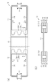
図1(a)は、本実施形態のループ型ヒートパイプ10を示す概略平面図である。図1(b)は、図1(a)において、A−A線で示す部分の断面図、つまり、第1のヒートパイプ部11の凝縮器22と第2のヒートパイプ部12の凝縮器32と連結部13の断面図である。図2は、第1のヒートパイプ部11の構成を示す概略平面図である。なお、図2には、図1(b)に示す金属層41〜46のうちの金属層41を除いたものが示されている。
(First Embodiment)
Hereinafter, the first embodiment will be described.
FIG. 1A is a schematic plan view showing the loop
図1(a)に示すように、ヒートパイプ10は平板状に形成されている。図1(a)及び図2に示すように、第1のヒートパイプ部11は、蒸発器21と凝縮器22とを有する。蒸発器21と凝縮器22には、蒸気管23と液管24とが接続されている。蒸発器21と凝縮器22は、蒸気管23と液管24とにより互いに連結される。そして、蒸発器21、蒸気管23、凝縮器22、液管24は、作動流体Cが流れるループ状の流路を形成する。本実施形態において、液管24の長さと蒸気管23の長さは、例えば互いに同じである。なお、液管24の長さと蒸気管23の長さは、異なっていてもよい。例えば、液管24の長さに比べて蒸気管23の長さが短くてもよい。
As shown in FIG. 1A, the
凝縮器22は、放熱用に面積を大きくした放熱プレート22pと、放熱プレート22pの内部において蛇行した流路22rとを有している。
図3に示すように、蒸発器21は、発熱部品111の上面に固定される。蒸発器21は、取付孔21Xに挿通されたネジ121と、ネジ121に螺入されたナット122とにより配線基板102に固定される。配線基板102には、発熱部品111が実装されている。蒸発器21は、発熱部品111の上面に密着される。なお、蒸発器21と発熱部品111との間に、熱伝導部材(TIM:Thermal Interface Material)が介在されてもよい。熱伝導部材は、発熱部品111と蒸発器21の間の接触熱抵抗を低減し、発熱部品111から蒸発器21への熱伝導をスムーズにする。
The
As shown in FIG. 3, the
蒸発器21において、発熱部品111の熱により図1(a)に示す作動流体Cの蒸気Cvが生成される。蒸気Cvは、蒸気管23を通って凝縮器22に導かれ、凝縮器22において液化する。この第1のヒートパイプ部11は、図3に示す発熱部品111で発生した熱を凝縮器22に移動し、その凝縮器22において放熱する。これにより、第1のヒートパイプ部11は、発熱部品111を冷却する。
In the
作動流体Cとしては、蒸気圧が高く、蒸発潜熱が大きい流体を使用するのが好ましい。このような作動流体Cを用いることで、蒸発潜熱によって発熱部品111を効率的に冷却できる。作動流体Cとしては、例えば、アンモニア、水、フロン、アルコール、アセトン、等を用いることができる。
As the working fluid C, it is preferable to use a fluid having a high vapor pressure and a large latent heat of vaporization. By using such a working fluid C, the
図1(a)に示すように、第2のヒートパイプ部12は、蒸発器31と凝縮器32とを有する。蒸発器31と凝縮器32には、蒸気管33と液管34とが接続されている。蒸発器31と凝縮器32は、蒸気管33と液管34とにより互いに連結される。そして、蒸発器31、蒸気管33、凝縮器32、及び液管34は、作動流体Cが流れるループ状の流路を形成する。本実施形態において、液管34の長さと蒸気管33の長さは、例えば互いに同じである。なお、液管24の長さと蒸気管23の長さは、異なっていてもよい。例えば、液管24の長さに比べて蒸気管23の長さが短くてもよい。
As shown in FIG. 1A, the second
凝縮器32は、放熱用に面積を大きくした放熱プレート32pと、放熱プレート32pの内部において蛇行した流路32rとを有している。
蒸発器31は、蒸発器21と同様に、発熱部品に固定される。第2のヒートパイプ部12は、第1のヒートパイプ部11と同様に、発熱部品で発生した熱を蒸発器31から凝縮器32に移動し、その凝縮器32において放熱する。これにより、第2のヒートパイプ部12は、発熱部品を冷却する。作動流体Cとしては、第1のヒートパイプ部11と同様のものを用いることができる。
The
The
図1(a),図1(b)に示すように、連結部13は、第1のヒートパイプ部11の凝縮器22と、第2のヒートパイプ部12の凝縮器32とを互いに連結する。連結部13は、図1(a)に2点鎖線にて示す位置にて折り曲げられる。
As shown in FIGS. 1A and 1B, the connecting
連結部13は、第1のヒートパイプ部11の凝縮器22の流路22rの管壁と第2のヒートパイプ部12の凝縮器32の流路32rの管壁と一体的に設けられている。
ヒートパイプ10は、複数(本実施形態では6層)の金属層41〜46を積層してなる。つまり、第1のヒートパイプ部11と第2のヒートパイプ部12は、6層の金属層41〜46を積層してなる。そして、本実施形態の連結部13は、6層の金属層41〜46のうちの少なくとも1層の金属層により形成される。例えば、図1(b)に示すように、本実施形態では、金属層43に連結部13が設けられている。
The connecting
The
なお、5層以下や7層以上の金属層を積層してヒートパイプ10(第1のヒートパイプ部11及び第2のヒートパイプ部12)を形成してもよい。また、2層以上の金属層により連結部13を形成してもよい。また、第1のヒートパイプ部11を形成する金属層の数と、第2のヒートパイプ部12を形成する金属層の数とを互いに異なるようにしてもよい。
The heat pipe 10 (first
各金属層41〜46としては、例えば熱伝導性の高い材料を用いることができる。このような材料としては、例えば、銅、銅合金、アルミニウム、アルミニウム合金、ステンレス、マグネシウム合金等を用いることができる。 As each of the metal layers 41 to 46, for example, a material having high thermal conductivity can be used. As such a material, for example, copper, copper alloy, aluminum, aluminum alloy, stainless steel, magnesium alloy and the like can be used.
本実施形態において、各金属層41〜46の材料として、熱伝導性に優れた銅が用いられている。各金属層41〜46は、積層方向(図1(b)の上下方向)において互いに接合されている。接合方法としては、例えば拡散接合、熱圧着等の固相接合を用いることができる。各金属層41〜46の厚さは、例えば100μm〜300μmとすることができる。なお、金属層41〜46の一部の金属層について、他の金属層と異なる材料を用いてもよい。
In this embodiment, copper having excellent thermal conductivity is used as the material for each of the metal layers 41 to 46. The metal layers 41 to 46 are joined to each other in the stacking direction (vertical direction in FIG. 1B). As the bonding method, for example, solid phase bonding such as diffusion bonding and thermocompression bonding can be used. The thickness of each
次に、第1のヒートパイプ部11の構成について詳述する。なお、第2のヒートパイプ部12については、第1のヒートパイプ部11と同様であるため、図面及び説明を省略する。
Next, the configuration of the first
図2に示すように、液管24には、多孔質体25が設けられている。多孔質体25は、液管24に沿って蒸発器21の近傍まで延びている。
図4は、図2のB−B線断面図である。図4に示すように、例えば、液管24の多孔質体25は、6層の金属層41〜46のうち、最上層の金属層41と最下層の金属層46を除く4層の金属層42〜45により形成される。なお、図4において、多孔質体25を形成する金属層42〜45の部分には、図2に示す多孔質体25に合わせて梨地のハッチングを付している。
As shown in FIG. 2, the
FIG. 4 is a cross-sectional view taken along the line BB of FIG. As shown in FIG. 4, for example, the
なお、図4では、各金属層41〜46を実線にて区別するように示している。上述のように、例えば、各金属層41〜46を拡散接合により一体化した場合、各金属層41〜46の界面は消失しており、境界は明確ではない。
In FIG. 4, each
各金属層42,43,44,45は、液管24の管壁24aを形成する壁部42a,43a,44a,45aと、壁部42a,43a,44a,45aの内側に配置される多孔質部42b,43b,44b,45bとを有している。積層された多孔質部42b,43b,44b,45bには、複数の貫通孔42X,43X,44X,45Xが形成されており、それらの間に作動流体Cが流れる微細な流路24bを形成する。この流路24bにより、毛細管力が生じ作動流体Cが液管24内を流れ易くなる。
The metal layers 42, 43, 44, 45 are porous arranged inside the
複数の貫通孔42X〜45Xは、例えば円形状に形成されている。そして、各貫通孔42X〜45Xは、上下方向に接する金属層42〜45の貫通孔42X〜45Xと一部が重なるように形成されている。
The plurality of through
図2に示すように、蒸発器21には、多孔質体26が設けられている。この多孔質体26の構成は、液管24の多孔質体25と同様とすることができる。
蒸発器21は、複数(図2では4つ)の取付孔21Xを有している。この取付孔21Xを利用して蒸発器21を図1(b)に示す配線基板102に固定することもできる。
As shown in FIG. 2, the
The
次に、本実施形態のヒートパイプ10の製造方法について説明する。
図5(a),図5(b),図5(c)は、ヒートパイプ10に使用する金属層の平面図である。
Next, a method of manufacturing the
5 (a), 5 (b), and 5 (c) are plan views of the metal layer used for the
図5(a)は、ヒートパイプ10の最上層と最下層に用いる金属層、つまり図1(b)に示す金属層41,46に使用する金属層71の平面図である。金属層71は、図1(a)に示す第1,第2のヒートパイプ部11,12に対応する形状に形成されている。金属層71は、例えばブリッジ(連結部材)により枠部(何れも図示略)に固定されている。
FIG. 5A is a plan view of the metal layers used for the uppermost layer and the lowermost layer of the
図5(b)は、最上層と最下層とを除く金属層のうち、図1(b)に示す連結部13を形成しない金属層42,44,45に使用する金属層72の平面図である。この金属層72は、第1,第2のヒートパイプ部11,12に対応する形状に形成されている。
FIG. 5 (b) is a plan view of the metal layers 72 used for the metal layers 42, 44, 45 that do not form the connecting
図5(c)は、図1(b)に示す連結部13を形成する金属層43に使用する金属層73の平面図である。この金属層73は、第1,第2のヒートパイプ部11,12と連結部13とに対応する形状に形成されている。
FIG. 5C is a plan view of the
図5(a)〜図5(c)に示す金属層71〜73は、例えば厚さが100μmの銅層を、例えばウエットエッチングにより所定の形状にパターニングすることで作成される。
図5(a)に示す金属層71には、第1のヒートパイプ部11と第2のヒートパイプ部12の凝縮器22,32を画定する開口部71Zが形成される。
The metal layers 71 to 73 shown in FIGS. 5 (a) to 5 (c) are created by, for example, patterning a copper layer having a thickness of 100 μm into a predetermined shape by wet etching, for example.
The
図5(b)に示す金属層72には、第1のヒートパイプ部11の蒸発器21、凝縮器22、蒸気管23、液管24と、第2のヒートパイプ部12の蒸発器31、凝縮器32、蒸気管33、液管34の流路に対応する開口部72Xを有する。また、金属層72には、第1のヒートパイプ部11と第2のヒートパイプ部12の凝縮器22,32を画定する開口部72Zが形成される。また、液管24,34に対応する部分の金属層72の多孔質部72aには、上述の多孔質体25を構成する貫通孔42X,44X,45X(図4参照)が設けられる。
The
図5(c)に示す金属層73には、図5(b)に示す金属層72と同様に、第1のヒートパイプ部11の蒸発器21、凝縮器22、蒸気管23、液管24と、第2のヒートパイプ部12の蒸発器31、凝縮器32、蒸気管33、液管34の流路に対応する開口部73Xを有する。また、液管24,34に対応する部分の金属層73の多孔質部73aには、上述の多孔質体25を構成する貫通孔43X(図4参照)が設けられる。
Similar to the
また、金属層73には、第1のヒートパイプ部11と第2のヒートパイプ部12の凝縮器22,32の放熱プレート22pと一体的に延在する連結部13が設けられている。金属層73には、第1のヒートパイプ部11と第2のヒートパイプ部12の凝縮器22,32を画定する金属層71の開口部71Zや金属層72の開口部72Zは形成されていない。
Further, the
なお、所定位置、例えば図1(b)に示す液管24,34に対応する部分の金属層には、作動流体Cを注入するための注入口(図示略)が設けられる。
次いで、図5(a)に示す金属層71を最上層と最下層とに配置し、それらの間に図5(b)や図5(c)に示す金属層72,73を配置する。
An injection port (not shown) for injecting the working fluid C is provided at a predetermined position, for example, in the metal layer of the portion corresponding to the
Next, the metal layers 71 shown in FIG. 5 (a) are arranged in the uppermost layer and the lowermost layer, and the metal layers 72 and 73 shown in FIGS. 5 (b) and 5 (c) are arranged between them.
そして、金属層71,72,73を所定温度(例えば、約900℃)に加熱しながら積層した金属層71,72,73をプレスすることにより、拡散接合にて金属層71,72,73を接合する。その後、図示しない真空ポンプを用いて液管24,34等を排気し、図示しない注入口から作動流体C(例えば水)を液管24,34に注入し、注入口を封止する。
Then, by pressing the laminated metal layers 71, 72, 73 while heating the metal layers 71, 72, 73 to a predetermined temperature (for example, about 900 ° C.), the metal layers 71, 72, 73 are formed by diffusion bonding. Join. After that, the
[本実施形態に係るループ型ヒートパイプの実装構造]
次に、本実施形態に係るループ型ヒートパイプの実装構造について、図1(a)や図6を用いて説明する。
[Mounting structure of loop type heat pipe according to this embodiment]
Next, the mounting structure of the loop type heat pipe according to the present embodiment will be described with reference to FIGS. 1A and 6A.
例えば図6に示す電子機器100に用いられる。先ず、電子機器100について説明する。
図6に示すように、電子機器100は、筐体101と、筐体101に収容された配線基板102とを有している。電子機器100は、例えばスマートフォンやタブレット等の薄型の機器である。
For example, it is used in the
As shown in FIG. 6, the
配線基板102は、図示しない支持部により、筐体101の内面101aから離間した位置に配設されている。配線基板102の上面102aには、第1の発熱部品111が実装されている。配線基板102の下面には、第2の発熱部品112が実装されている。第1,第2の発熱部品111,112は、例えば、CPU(Central Processing Unit)やGPU(Graphics Processing Unit)等の半導体装置、等である。
The
ヒートパイプ10は、第1のヒートパイプ部11と、第2のヒートパイプ部12と、連結部13とを有している。第1のヒートパイプ部11は、配線基板102の上面102aの側に、上面102aと平行に配設されている。第2のヒートパイプ部12は、配線基板102の下面102bの側に、下面102bと平行に配設されている。第1のヒートパイプ部11は、配線基板102の上面102aに実装された第1の発熱部品111を冷却する。第2のヒートパイプ部12は、配線基板102の下面102bに実装された第2の発熱部品112を冷却する。
The
連結部13は、第1のヒートパイプ部11と第2のヒートパイプ部12とを互いに連結する。また、連結部13は、第1のヒートパイプ部11と第2のヒートパイプ部12とを互いに平行に保持する。連結部13は、折り曲げ可能である。連結部13を所定の位置にて折り曲げることにより、第1のヒートパイプ部11と第2のヒートパイプ部12とを互いに平行とすることができる。蒸発器31は、図6に示す第2の発熱部品112の下面に固定される。
The connecting
連結部13は、折り曲げられる。第1のヒートパイプ部11は、配線基板102の上面102aの側に配置され、第2のヒートパイプ部12は、配線基板102の下面102bの側に配置される。第2のヒートパイプ部12は、連結部13を介して第1のヒートパイプ部11により保持される。このため、配線基板102の下面102bの側に配置された第2のヒートパイプ部12を例えば筐体101等に固定することなく、配置された位置を維持する。つまり、第2のヒートパイプ部12の姿勢を維持する。
The connecting
このように、連結部13を介して第2のヒートパイプ部12の姿勢が維持されるため、単体の第2のヒートパイプ部12を例えば配線基板102や筐体101等に固定する必要がない。このため、配線基板102や筐体101、つまり電子機器100の設計の自由度が向上する。また、第2のヒートパイプ部12を固定するための部材を必要としないため、電子機器100を軽量化できる。
In this way, since the posture of the second
(作用)
図1(a)に示すように、本実施形態のヒートパイプ10は、第1のヒートパイプ部11と、第2のヒートパイプ部12と、第1のヒートパイプ部11と第2のヒートパイプ部12とを連結する連結部13とを有している。第1のヒートパイプ部11は、蒸発器21、凝縮器22、蒸気管23、液管24、を有している。第2のヒートパイプ部12は、蒸発器31、凝縮器32、蒸気管33、液管34、を有している。
(Action)
As shown in FIG. 1A, the
連結部13は、折り曲げられる。第1のヒートパイプ部11は、配線基板102の上面102aの側に配置され、第2のヒートパイプ部12は、配線基板102の下面102bの側に配置される。第2のヒートパイプ部12は、連結部13を介して第1のヒートパイプ部11により保持される。このため、配線基板102の下面102bの側に配置された第2のヒートパイプ部12を例えば筐体101等に固定することなく、配置された位置を維持する。つまり、第2のヒートパイプ部12の姿勢を維持する。
The connecting
このように、連結部13を介して第2のヒートパイプ部12の姿勢が維持されるため、単体の第2のヒートパイプ部12を例えば配線基板102や筐体101等に固定する必要がない。このため、配線基板102や筐体101、つまり電子機器100の設計の自由度が向上する。
In this way, since the posture of the second
第1のヒートパイプ部11と第2のヒートパイプ部12は、複数の金属層41〜46を積層して形成される。そして、連結部13は、複数の金属層41〜46のうちの少なくとも1層の金属層43により形成される。このため、連結のための部材を別に用いるものと比べ、第1のヒートパイプ部11と第2のヒートパイプ部12とを有するループ型ヒートパイプ10の形成が容易である。また、連結部13を1層の金属層により形成することで、曲げが容易にできる。
The first
連結部13は、第1のヒートパイプ部11の凝縮器22と、第2のヒートパイプ部12の凝縮器32とを互いに連結する。そして、連結部13は、第1のヒートパイプ部11と第2のヒートパイプ部12とを形成する複数の金属層41〜46のうちの金属層43により形成される。凝縮器22,32の熱は、凝縮器22,32それぞれから放熱されるとともに、連結部13に伝達してその連結部13から放熱される。従って、ヒートパイプ10において放熱に寄与する部分の表面積は、連結部13により、それぞれ単体の凝縮器22,32の表面積の合計値よりも大きくなる。これにより、凝縮器22,32における放熱効率が向上する。
The connecting
以上記述したように、本実施形態によれば、以下の効果を奏する。
(1−1)ヒートパイプ10は、第1のヒートパイプ部11と、第2のヒートパイプ部12と、第1のヒートパイプ部11と第2のヒートパイプ部12とを連結する連結部13とを有している。第1のヒートパイプ部11は、蒸発器21、凝縮器22、蒸気管23、液管24、を有している。第2のヒートパイプ部12は、蒸発器31、凝縮器32、蒸気管33、液管34、を有している。連結部13は、折り曲げられる。第1のヒートパイプ部11は、配線基板102の上面102aの側に配置され、第2のヒートパイプ部12は、配線基板102の下面102bの側に配置される。第2のヒートパイプ部12は、連結部13を介して第1のヒートパイプ部11により保持される。このため、配線基板102の下面102bの側に配置された第2のヒートパイプ部12を例えば筐体101等に固定することなく、第2のヒートパイプ部12の姿勢を維持できる。
As described above, according to the present embodiment, the following effects are obtained.
(1-1) The
(1−2)第1のヒートパイプ部11と第2のヒートパイプ部12は、複数の金属層41〜46を積層して形成される。そして、連結部13は、複数の金属層41〜46のうちの少なくとも1層の金属層43により形成される。このため、第1のヒートパイプ部11と第2のヒートパイプ部12とを容易に連結できる。
(1-2) The first
(1−3)連結部13は、第1のヒートパイプ部11の凝縮器22と、第2のヒートパイプ部12の凝縮器32とを互いに連結する。そして、連結部13は、第1のヒートパイプ部11と第2のヒートパイプ部12とを形成する複数の金属層41〜46のうちの少なくとも1層の金属層43により形成される。従って、ヒートパイプ10において放熱に寄与する部分の表面積は、連結部13により、それぞれ単体の凝縮器22,32の表面積の合計値よりも大きくなる。これにより、凝縮器22,32における放熱効率を向上できる。そして、第1のヒートパイプ部11と第2のヒートパイプ部12とにより第1の発熱部品111と第2の発熱部品112とを効率よく冷却できる。
(1-3) The connecting
(変形例)
尚、上記各実施形態は、以下の態様で実施してもよい。
・上記各実施形態に対し、ヒートパイプの形状等を適宜変更してもよい。
(Modification example)
In addition, each of the above-mentioned embodiments may be carried out in the following embodiments.
-The shape of the heat pipe and the like may be appropriately changed for each of the above embodiments.
図7に示すループ型ヒートパイプ300は、第1のヒートパイプ部301と、第2のヒートパイプ部302と、連結部303とを有している。第1のヒートパイプ部301は、蒸発器311と、凝縮器312と、蒸発器311と凝縮器312とを接続する蒸気管313及び液管314を有している。第2のヒートパイプ部302は、蒸発器321と、凝縮器322と、蒸発器321と凝縮器322とを接続する蒸気管323及び液管324を有している。連結部303は、第1のヒートパイプ部301の凝縮器312と第2のヒートパイプ部302の凝縮器322とを連結する。そして、このヒートパイプ300では、第1のヒートパイプ部301と第2のヒートパイプ部302とがそれぞれの凝縮器312,322に対して蒸発器311,321が同一方向となるように、連結部303が形成されている。このヒートパイプ300においても、連結部303を2点鎖線にて示す箇所にて折り曲げることで、第1のヒートパイプ部301と第2のヒートパイプ部302とを互いに平行とするように配置できる。そして、上述した第1実施形態と同様に、第1のヒートパイプ部301と第2のヒートパイプ部302とを図6に示す配線基板102の上面102aの側と下面102bの側とに配置することで、配線基板102の上面102aの第1の発熱部品111と下面102bの第2の発熱部品112とを冷却できる。そして、第1のヒートパイプ部301と第2のヒートパイプ部302とが連結部303により連結されているため、配線基板102の下面102bの側に配置した第2のヒートパイプ部302は、連結部303を介して、配線基板102の上面102aの側に配置した第1のヒートパイプ部301により保持される。これにより、第2のヒートパイプ部302の姿勢を維持できる。
The loop
図8に示すループ型ヒートパイプ400は、第1のヒートパイプ部401と、第2のヒートパイプ部402と、連結部403とを有している。第1のヒートパイプ部401は、蒸発器411と、凝縮器412と、蒸発器411と凝縮器412とを接続する蒸気管413及び液管414を有している。第2のヒートパイプ部402は、蒸発器421と、凝縮器422と、蒸発器421と凝縮器422とを接続する蒸気管423及び液管424を有している。第1のヒートパイプ部401の凝縮器412の大きさ(連結部403に沿った方向、図において上下方向)の長さと第2のヒートパイプ部402の凝縮器422の長さが互いに異なる。第1のヒートパイプ部401と第2のヒートパイプ部402は、発熱部品の位置や発熱量に応じて設定される。つまり、配線基板において、発熱部品の実装位置の自由度が高い、つまり配線基板の設計自由度が向上できる。
The loop
図9に示すループ型ヒートパイプ500は、3つのヒートパイプ部501,502,503を有し、それらは連結部504を介して互いに接続されている。このように、3つのヒートパイプ部を有するヒートパイプ500においても、ヒートパイプの姿勢を維持し、3つの発熱部品を冷却することができる。
The loop
・上記各実施形態に対し、連結部及びその近傍の形状を適宜変更してもよい。
図10(a)に示すように、連結部601の上面601aに溝部602を形成してもよい。溝部602は、図1(a)に示す2点鎖線に沿って延びるように形成される。このように、連結部601に溝部602を形成することで、ループ型ヒートパイプを折り曲げ易い。
-For each of the above embodiments, the shape of the connecting portion and its vicinity may be appropriately changed.
As shown in FIG. 10A, the
また、図10(a)に示すように、連結部611の上面611aに溝部612aを形成するとともに、連結部611の下面611bに溝部612bを形成してもよい。これらの溝部612a,612bにより、ループ型ヒートパイプを図10(b)に上面611aの側と下面611bの側とのそれぞれ折り曲げ易い。
Further, as shown in FIG. 10A, the
なお、連結部601,611の溝部は、折り曲げ位置に応じて形成されればよく、例えば、連結部601,611の中央部分に溝部が形成されてもよい。つまり、1箇所にてループ型ヒートパイプを折り曲げるようにしてもよい。
The groove portion of the connecting
溝部は、折り曲げ位置以外に形成されてもよい。また、溝部は、折り曲げ位置(図1(a)に示す2点鎖線)に対して所定の角度となるように形成されてもよい。また、複数の溝部が交差するように形成されてもよい。これらの溝部は、連結部の表面積を増加させる。これにより、ヒートパイプにおいて放熱に寄与する部分の表面積がより増加するため、放熱性を向上できる。 The groove may be formed at a position other than the bent position. Further, the groove portion may be formed so as to have a predetermined angle with respect to the bent position (two-dot chain line shown in FIG. 1A). Further, a plurality of grooves may be formed so as to intersect with each other. These grooves increase the surface area of the connecting part. As a result, the surface area of the portion of the heat pipe that contributes to heat dissipation is further increased, so that heat dissipation can be improved.
・上記実施形態に対し、積層する金属層の形状を適宜変更してもよい。
図11に示すように、ループ型ヒートパイプ700は6層の金属層701〜706を積層して形成される。金属層703により連結部713が形成される。その金属層703より上側の金属層702は、連結部713の中央部に向かって延出している。また、連結部713となる金属層703より下側の金属層704,705は、連結部713の中央部に延出している。これにより、第1のヒートパイプ部711の凝縮器722と第2のヒートパイプ部712の凝縮器732の表面積が大きくなり、放熱性が向上する。延出する金属層の数、金属層702,704,705を延出する長さ、等により表面積を調整できる。
-The shape of the metal layer to be laminated may be appropriately changed with respect to the above embodiment.
As shown in FIG. 11, the loop
・上記各実施形態に対し、放熱部を適宜接続するようにしてもよい。
図12(a)に示すように、接続部材105より連結部13を配線基板102の側面102cに固定するようにしてもよい。接続部材105としては、例えば接着剤を用いることができる。連結部13を配線基板102に固定することで、ヒートパイプ10の姿勢維持を向上できる。
-The heat radiating unit may be appropriately connected to each of the above embodiments.
As shown in FIG. 12A, the connecting
図12(b)に示すように、ヒートシンク106に連結部13を接続してもよい。ヒートシンク106は、筐体101の内面101aに接続される。これにより、熱を筐体101の外部へと効率よく放熱できる。ヒートシンク106と連結部13との間に、熱伝導部材(TIM)を介在させてもよく、連結部13からヒートシンク106への熱伝導をスムーズにできる。また、ヒートシンク106と筐体101との間に熱伝導部材(TIM)を介在させてもよく、ヒートシンク106から筐体101への熱伝導をスムーズにできる。
As shown in FIG. 12B, the connecting
・上記実施形態では、図6に示すように、連結部13を90度に折り曲げたU字形状とした。これに対し、連結部13の折り曲げ形状は、上記実施形態に限定されず、L字形状、V字形状、Z字形状、等の任意の形状としてもよい。また、90度以上の角度に開いて折り曲げられた段形状、等とすることもできる。
-In the above embodiment, as shown in FIG. 6, the connecting
図13に示すように、例えば、配線基板102の上面102aに、高さの異なる発熱部品111,112が実装されている場合、連結部13を90度以上の角度に開いて折り曲げられた段形状とすることができる。連結部13をこのような折り曲げ形状とすることにより、発熱部品111,112の上面にヒートパイプ10の蒸発器21,31を密着して固定できる。また、ヒートパイプ10の姿勢維持を向上できる。また、ヒートパイプ10において放熱に寄与する部分の表面積は、連結部13により、それぞれ単体の凝縮器22,32の表面積の合計値よりも大きくなり、凝縮器22,32における放熱効率を向上できる。
As shown in FIG. 13, for example, when
10 ループ型ヒートパイプ
11 第1のヒートパイプ部
12 第2のヒートパイプ部
13 連結部
21,31 蒸発器
22,32 凝縮器
23,33 蒸気管
24,34 液管
100 電子機器
102 配線基板
111 第1の発熱部品
112 第2の発熱部品
10 Loop
Claims (11)
作動流体を気化させる第2蒸発器と、前記第2蒸発器において気化した前記作動流体を液化する第2凝縮器と、前記第2蒸発器において気化した前記作動流体を前記第2凝縮器に流入させる第2蒸気管と、前記第2凝縮器において液化した前記作動流体を前記第2蒸発器に流入させる第2液管とを有する第2のヒートパイプ部と、
前記第1凝縮器と前記第2凝縮器のみを連結する連結部と、
を有し、
前記第1のヒートパイプ部と前記第2のヒートパイプ部は、複数の金属層を積層してなり、
前記連結部は、前記複数の金属層のうちの少なくとも1層の金属層からなること、
ことを特徴とするループ型ヒートパイプ。 A first evaporator that vaporizes the working fluid, a first condenser that liquefies the working fluid vaporized in the first evaporator, and the working fluid vaporized in the first evaporator flow into the first condenser. A first heat pipe portion having a first steam pipe for causing the vaporization and a first liquid pipe for flowing the working fluid liquefied in the first condenser into the first evaporator.
A second evaporator that vaporizes the working fluid, a second condenser that liquefies the working fluid vaporized in the second evaporator, and the working fluid vaporized in the second evaporator flow into the second condenser. A second heat pipe portion having a second steam pipe for causing the vaporization and a second liquid pipe for allowing the working fluid liquefied in the second condenser to flow into the second evaporator.
A connecting portion that connects only the first condenser and the second condenser,
Have,
The first heat pipe portion and the second heat pipe portion are formed by laminating a plurality of metal layers.
The connecting portion shall be composed of at least one metal layer among the plurality of metal layers.
A loop type heat pipe characterized by that.
前記第1のヒートパイプ部の上面及び前記第2のヒートパイプ部の上面を含む最上層の金属層と、
前記第1のヒートパイプ部の下面及び前記第2のヒートパイプ部の下面を含む最下層の金属層と、
前記最上層の金属層と前記最下層の金属層との間に位置する1つ又は複数の中間金属層とを含み、
前記連結部は、前記1つ又は複数の中間金属層のうちの少なくとも1つからなること、を特徴とする請求項1又は請求項2に記載のループ型ヒートパイプ。 The plurality of metal layers are
An uppermost metal layer including the upper surface of the first heat pipe portion and the upper surface of the second heat pipe portion, and
The lowermost metal layer including the lower surface of the first heat pipe portion and the lower surface of the second heat pipe portion, and
Includes one or more intermediate metal layers located between the top metal layer and the bottom metal layer.
The loop type heat pipe according to claim 1 or 2, wherein the connecting portion is composed of at least one of the one or a plurality of intermediate metal layers.
前記連結部を形成する前記少なくとも1層の金属層を除く前記複数の金属層のうちの少なくとも1層は、前記第1凝縮器の表面積及び前記第2凝縮器の表面積のうちの少なくとも一方を大きくするように前記連結部の中央に向かって延出していること、を請求項1〜3のいずれか1項に記載のループ型ヒートパイプ。 The number of the at least one metal layer forming the connecting portion is less than the number of the plurality of metal layers.
At least one of the plurality of metal layers excluding the at least one metal layer forming the connecting portion has a large surface area of the first condenser and at least one of the surface areas of the second condenser. The loop type heat pipe according to any one of claims 1 to 3, wherein the connecting portion extends toward the center of the connecting portion.
前記配線基板の下面に実装された第2の発熱部品と、
前記第1の発熱部品及び前記第2の発熱部品を冷却するループ型ヒートパイプと、
を有し、
前記ループ型ヒートパイプは、
前記第1の発熱部品の熱により作動流体を気化させる第1蒸発器と、前記第1蒸発器において気化した前記作動流体を液化する第1凝縮器と、前記第1蒸発器において気化した前記作動流体を前記第1凝縮器に流入させる第1蒸気管と、前記第1凝縮器において液化した前記作動流体を前記第1蒸発器に流入させる第1液管とを有する第1のヒートパイプ部と、
前記第2の発熱部品の熱により作動流体を気化させる第2蒸発器と、前記第2蒸発器において気化した前記作動流体を液化する第2凝縮器と、前記第2蒸発器において気化した前記作動流体を前記第2凝縮器に流入させる第2蒸気管と、前記第2凝縮器において液化した前記作動流体を前記第2蒸発器に流入させる第2液管とを有する第2のヒートパイプ部と、
前記第1凝縮器と前記第2凝縮器とを連結する連結部と、
を有し、
前記第1のヒートパイプ部と前記第2のヒートパイプ部は、複数の金属層を積層してなり、
前記連結部は、前記複数の金属層の少なくとも1層の金属層からなる、電子機器。 The first heat-generating component mounted on the upper surface of the wiring board,
A second heat generating component mounted on the lower surface of the wiring board, and
A loop type heat pipe for cooling the first heat generating component and the second heat generating component, and
Have,
The loop type heat pipe
A first evaporator that vaporizes the working fluid by the heat of the first heat generating component, a first condenser that liquefies the working fluid vaporized in the first evaporator, and the operation vaporized in the first evaporator. A first heat pipe portion having a first steam pipe for flowing fluid into the first condenser and a first liquid pipe for flowing the working fluid liquefied in the first condenser into the first evaporator. ,
A second evaporator that vaporizes the working fluid by the heat of the second heat generating component, a second condenser that liquefies the working fluid vaporized in the second evaporator, and the operation vaporized in the second evaporator. A second heat pipe portion having a second steam pipe for flowing the fluid into the second condenser and a second liquid pipe for flowing the working fluid liquefied in the second condenser into the second evaporator. ,
A connecting portion that connects the first condenser and the second condenser,
Have,
The first heat pipe portion and the second heat pipe portion are formed by laminating a plurality of metal layers.
The connecting portion is an electronic device composed of at least one metal layer of the plurality of metal layers.
前記配線基板、前記第1の発熱部品、前記第2の発熱部品、前記ループ型ヒートパイプ、及び前記ヒートシンクを収容する筐体と、を更に備え、
前記ヒートシンクは、前記筐体の内面及び前記連結部に接続されている、
請求項7に記載の電子機器。 With a heat sink
The wiring board, the first heat generating component, the second heat generating component, the loop type heat pipe, and the housing for accommodating the heat sink are further provided.
The heat sink is connected to the inner surface of the housing and the connecting portion.
The electronic device according to claim 7.
前記第1の発熱部品及び前記第2の発熱部品を冷却するループ型ヒートパイプと、
を有し、
前記ループ型ヒートパイプは、
前記第1の発熱部品の熱により作動流体を気化させる第1蒸発器と、前記第1蒸発器において気化した前記作動流体を液化する第1凝縮器と、前記第1蒸発器において気化した前記作動流体を前記第1凝縮器に流入させる第1蒸気管と、前記第1凝縮器において液化した前記作動流体を前記第1蒸発器に流入させる第1液管とを有する第1のヒートパイプ部と、
前記第2の発熱部品の熱により作動流体を気化させる第2蒸発器と、前記第2蒸発器において気化した前記作動流体を液化する第2凝縮器と、前記第2蒸発器において気化した前記作動流体を前記第2凝縮器に流入させる第2蒸気管と、前記第2凝縮器において液化した前記作動流体を前記第2蒸発器に流入させる第2液管とを有する第2のヒートパイプ部と、
前記第1凝縮器と前記第2凝縮器のみを連結する連結部と、
を有し、
前記第1のヒートパイプ部と前記第2のヒートパイプ部は、複数の金属層を積層してなり、
前記連結部は、前記複数の金属層の少なくとも1層の金属層からなる、電子機器。 The first heat-generating component and the second heat-generating component mounted on the upper surface of the wiring board,
A loop type heat pipe for cooling the first heat generating component and the second heat generating component, and
Have,
The loop type heat pipe
A first evaporator that vaporizes the working fluid by the heat of the first heat generating component, a first condenser that liquefies the working fluid vaporized in the first evaporator, and the operation vaporized in the first evaporator. A first heat pipe portion having a first steam pipe for flowing fluid into the first condenser and a first liquid pipe for flowing the working fluid liquefied in the first condenser into the first evaporator. ,
A second evaporator that vaporizes the working fluid by the heat of the second heat generating component, a second condenser that liquefies the working fluid vaporized in the second evaporator, and the operation vaporized in the second evaporator. A second heat pipe portion having a second steam pipe for flowing the fluid into the second condenser and a second liquid pipe for flowing the working fluid liquefied in the second condenser into the second evaporator. ,
A connecting portion that connects only the first condenser and the second condenser,
Have,
The first heat pipe portion and the second heat pipe portion are formed by laminating a plurality of metal layers.
The connecting portion is an electronic device composed of at least one metal layer of the plurality of metal layers.
Priority Applications (4)
| Application Number | Priority Date | Filing Date | Title |
|---|---|---|---|
| JP2017180367A JP6886904B2 (en) | 2017-09-20 | 2017-09-20 | Loop type heat pipe, manufacturing method of loop type heat pipe, electronic equipment |
| CN201810908528.7A CN109520340B (en) | 2017-09-20 | 2018-08-10 | Loop heat pipe, method for manufacturing loop heat pipe, and electronic apparatus |
| US16/114,864 US10524388B2 (en) | 2017-09-20 | 2018-08-28 | Loop heat pipe and electronic device |
| EP18192738.5A EP3460375B1 (en) | 2017-09-20 | 2018-09-05 | Loop heat pipe, method for manufacturing loop heat pipe, and electronic device |
Applications Claiming Priority (1)
| Application Number | Priority Date | Filing Date | Title |
|---|---|---|---|
| JP2017180367A JP6886904B2 (en) | 2017-09-20 | 2017-09-20 | Loop type heat pipe, manufacturing method of loop type heat pipe, electronic equipment |
Publications (3)
| Publication Number | Publication Date |
|---|---|
| JP2019056511A JP2019056511A (en) | 2019-04-11 |
| JP2019056511A5 JP2019056511A5 (en) | 2020-04-16 |
| JP6886904B2 true JP6886904B2 (en) | 2021-06-16 |
Family
ID=63517771
Family Applications (1)
| Application Number | Title | Priority Date | Filing Date |
|---|---|---|---|
| JP2017180367A Active JP6886904B2 (en) | 2017-09-20 | 2017-09-20 | Loop type heat pipe, manufacturing method of loop type heat pipe, electronic equipment |
Country Status (4)
| Country | Link |
|---|---|
| US (1) | US10524388B2 (en) |
| EP (1) | EP3460375B1 (en) |
| JP (1) | JP6886904B2 (en) |
| CN (1) | CN109520340B (en) |
Families Citing this family (15)
| Publication number | Priority date | Publication date | Assignee | Title |
|---|---|---|---|---|
| JP6860086B2 (en) * | 2017-11-29 | 2021-04-14 | 富士通株式会社 | Loop heat pipes and electronics |
| US10718558B2 (en) * | 2017-12-11 | 2020-07-21 | Global Cooling, Inc. | Independent auxiliary thermosiphon for inexpensively extending active cooling to additional freezer interior walls |
| JP6920231B2 (en) * | 2018-02-06 | 2021-08-18 | 新光電気工業株式会社 | Loop type heat pipe |
| JP6801698B2 (en) * | 2018-09-04 | 2020-12-16 | セイコーエプソン株式会社 | Cooling device and projector |
| JP7210379B2 (en) * | 2019-05-31 | 2023-01-23 | 新光電気工業株式会社 | loop heat pipe |
| JP7305512B2 (en) * | 2019-10-17 | 2023-07-10 | 新光電気工業株式会社 | Loop type heat pipe and its manufacturing method |
| JP7353132B2 (en) * | 2019-10-31 | 2023-09-29 | 新光電気工業株式会社 | Loop type heat pipe and its manufacturing method |
| JP7372185B2 (en) * | 2020-03-17 | 2023-10-31 | 新光電気工業株式会社 | Loop type heat pipe and its manufacturing method |
| JP7390252B2 (en) * | 2020-05-12 | 2023-12-01 | 新光電気工業株式会社 | loop heat pipe |
| JP7394708B2 (en) * | 2020-06-18 | 2023-12-08 | 新光電気工業株式会社 | loop heat pipe |
| JP7427564B2 (en) | 2020-09-07 | 2024-02-05 | 新光電気工業株式会社 | Electronics |
| JP2023012839A (en) * | 2021-07-14 | 2023-01-26 | 新光電気工業株式会社 | Loop type heat pipe |
| JP7273116B2 (en) * | 2021-08-27 | 2023-05-12 | レノボ・シンガポール・プライベート・リミテッド | Electronics and cooling modules |
| JP2023068386A (en) * | 2021-11-02 | 2023-05-17 | 新光電気工業株式会社 | Electronic apparatus |
| JP2023120521A (en) * | 2022-02-18 | 2023-08-30 | 新光電気工業株式会社 | Loop type heat pipe |
Family Cites Families (28)
| Publication number | Priority date | Publication date | Assignee | Title |
|---|---|---|---|---|
| JP2000277963A (en) * | 1999-03-24 | 2000-10-06 | Fujikura Ltd | Cooling device for personal computer |
| US7775261B2 (en) * | 2002-02-26 | 2010-08-17 | Mikros Manufacturing, Inc. | Capillary condenser/evaporator |
| JP4057455B2 (en) | 2002-05-08 | 2008-03-05 | 古河電気工業株式会社 | Thin sheet heat pipe |
| EP1531384A3 (en) * | 2003-11-14 | 2006-12-06 | LG Electronics Inc. | Cooling apparatus for portable computer |
| CN100343785C (en) * | 2005-01-10 | 2007-10-17 | 富准精密工业(深圳)有限公司 | Pulsating type heat transmission device |
| JP4496999B2 (en) * | 2005-03-18 | 2010-07-07 | ソニー株式会社 | Heat transport device and electronic equipment |
| TWI262285B (en) * | 2005-06-03 | 2006-09-21 | Foxconn Tech Co Ltd | Loop-type heat exchange apparatus |
| US8720530B2 (en) * | 2006-05-17 | 2014-05-13 | The Boeing Company | Multi-layer wick in loop heat pipe |
| JP4719079B2 (en) * | 2006-05-19 | 2011-07-06 | 株式会社東芝 | Electronics |
| US20090323276A1 (en) * | 2008-06-25 | 2009-12-31 | Mongia Rajiv K | High performance spreader for lid cooling applications |
| JP4811460B2 (en) | 2008-12-24 | 2011-11-09 | ソニー株式会社 | Heat transport device and electronic equipment |
| JP2010151352A (en) * | 2008-12-24 | 2010-07-08 | Sony Corp | Method of manufacturing heat transport device, and heat transport device |
| JP5218660B2 (en) | 2009-07-13 | 2013-06-26 | 富士通株式会社 | Loop heat pipe and method for starting the same |
| JP5471119B2 (en) | 2009-07-24 | 2014-04-16 | 富士通株式会社 | Loop heat pipe, electronic device |
| WO2013027737A1 (en) * | 2011-08-25 | 2013-02-28 | 日本電気株式会社 | Electronic board and electronic device |
| JP6182449B2 (en) * | 2013-12-13 | 2017-08-16 | 昭和電工株式会社 | LED lighting heat dissipation device |
| WO2015087451A1 (en) | 2013-12-13 | 2015-06-18 | 富士通株式会社 | Loop-type heat pipe, method for manufacturing same, and electronic equipment |
| EP3096103B1 (en) | 2014-01-16 | 2022-06-22 | Nec Corporation | Cooling apparatus and electronic apparatus |
| JP6233125B2 (en) * | 2014-03-20 | 2017-11-22 | 富士通株式会社 | Loop-type heat pipe, manufacturing method thereof, and electronic device |
| JP6327029B2 (en) * | 2014-07-14 | 2018-05-23 | 富士通株式会社 | LAMINATED STRUCTURE HAVING INTERNAL COMMUNICATION SPACE AND ITS MANUFACTURING METHOD |
| JP2016090204A (en) | 2014-11-11 | 2016-05-23 | 富士通株式会社 | Loop type heat pipe and electronic equipment |
| CN205430849U (en) * | 2015-11-26 | 2016-08-03 | 富葵精密组件(深圳)有限公司 | Flexible even temperature plate |
| JP6291000B2 (en) * | 2016-09-01 | 2018-03-07 | 新光電気工業株式会社 | Loop heat pipe and manufacturing method thereof |
| JP6886877B2 (en) * | 2017-07-12 | 2021-06-16 | 新光電気工業株式会社 | Loop type heat pipe and its manufacturing method |
| CN207729869U (en) * | 2017-12-28 | 2018-08-14 | 广东志高暖通设备股份有限公司 | A kind of air-conditioning heat exchanger and a kind of air-conditioning equipment |
| JP6951267B2 (en) * | 2018-01-22 | 2021-10-20 | 新光電気工業株式会社 | Heat pipe and its manufacturing method |
| JP7028659B2 (en) * | 2018-01-30 | 2022-03-02 | 新光電気工業株式会社 | Manufacturing method of loop type heat pipe and loop type heat pipe |
| US11573055B2 (en) * | 2019-12-27 | 2023-02-07 | Intel Corporation | Vapor chamber and means of attachment |
-
2017
- 2017-09-20 JP JP2017180367A patent/JP6886904B2/en active Active
-
2018
- 2018-08-10 CN CN201810908528.7A patent/CN109520340B/en active Active
- 2018-08-28 US US16/114,864 patent/US10524388B2/en active Active
- 2018-09-05 EP EP18192738.5A patent/EP3460375B1/en active Active
Also Published As
| Publication number | Publication date |
|---|---|
| US20190090385A1 (en) | 2019-03-21 |
| US10524388B2 (en) | 2019-12-31 |
| EP3460375A1 (en) | 2019-03-27 |
| EP3460375B1 (en) | 2022-03-16 |
| CN109520340A (en) | 2019-03-26 |
| JP2019056511A (en) | 2019-04-11 |
| CN109520340B (en) | 2022-10-14 |
Similar Documents
| Publication | Publication Date | Title |
|---|---|---|
| JP6886904B2 (en) | Loop type heat pipe, manufacturing method of loop type heat pipe, electronic equipment | |
| JP4427445B2 (en) | Vapor enhanced heat sink with multi-wick structure | |
| JP6799503B2 (en) | Heat pipe and its manufacturing method | |
| US20130020053A1 (en) | Low-profile heat-spreading liquid chamber using boiling | |
| JP2008522129A (en) | Steam chamber with boil-enhancing multi-wick structure | |
| US20220011055A1 (en) | Flat loop heat pipe | |
| WO2005125297A2 (en) | Cooling electronic devices in computer systems | |
| US11060798B2 (en) | Loop heat pipe | |
| US10712098B2 (en) | Loop heat pipe and method of manufacturing loop heat pipe | |
| JP6413306B2 (en) | Heat pipe built-in frame plate and electronic equipment | |
| JP6988681B2 (en) | Heat pipes and electronic devices | |
| JP7260719B2 (en) | Micro-channel pulsating heat pipe | |
| JP4496999B2 (en) | Heat transport device and electronic equipment | |
| US20110240263A1 (en) | Enhanced Electronic Cooling by an Inner Fin Structure in a Vapor Chamber | |
| JPWO2013005622A1 (en) | Cooling device and manufacturing method thereof | |
| JP2019015420A (en) | Heat pipe and method for manufacturing heat pipe | |
| JP2012237491A (en) | Flat cooling device, method for manufacturing the same and method for using the same | |
| JP6197651B2 (en) | Cooling system | |
| JP6277598B2 (en) | COOLING MODULE, LAMINATED SEMICONDUCTOR INTEGRATED CIRCUIT DEVICE, AND COOLING MODULE MANUFACTURING METHOD | |
| JP6863058B2 (en) | Heat pipes and electronic devices | |
| JP7394708B2 (en) | loop heat pipe | |
| JP7336416B2 (en) | loop heat pipe | |
| JP7390252B2 (en) | loop heat pipe | |
| JP2017152657A (en) | Cooling device and electronic apparatus | |
| JPWO2013111561A1 (en) | COOLING STRUCTURE AND ELECTRONIC DEVICE USING THE SAME |
Legal Events
| Date | Code | Title | Description |
|---|---|---|---|
| A521 | Request for written amendment filed |
Free format text: JAPANESE INTERMEDIATE CODE: A523 Effective date: 20200306 |
|
| A621 | Written request for application examination |
Free format text: JAPANESE INTERMEDIATE CODE: A621 Effective date: 20200306 |
|
| A977 | Report on retrieval |
Free format text: JAPANESE INTERMEDIATE CODE: A971007 Effective date: 20210201 |
|
| A131 | Notification of reasons for refusal |
Free format text: JAPANESE INTERMEDIATE CODE: A131 Effective date: 20210216 |
|
| A521 | Request for written amendment filed |
Free format text: JAPANESE INTERMEDIATE CODE: A523 Effective date: 20210402 |
|
| TRDD | Decision of grant or rejection written | ||
| A01 | Written decision to grant a patent or to grant a registration (utility model) |
Free format text: JAPANESE INTERMEDIATE CODE: A01 Effective date: 20210420 |
|
| A61 | First payment of annual fees (during grant procedure) |
Free format text: JAPANESE INTERMEDIATE CODE: A61 Effective date: 20210517 |
|
| R150 | Certificate of patent or registration of utility model |
Ref document number: 6886904 Country of ref document: JP Free format text: JAPANESE INTERMEDIATE CODE: R150 |