JP7204374B2 - Loop type heat pipe and its manufacturing method - Google Patents
Loop type heat pipe and its manufacturing method Download PDFInfo
- Publication number
- JP7204374B2 JP7204374B2 JP2018152493A JP2018152493A JP7204374B2 JP 7204374 B2 JP7204374 B2 JP 7204374B2 JP 2018152493 A JP2018152493 A JP 2018152493A JP 2018152493 A JP2018152493 A JP 2018152493A JP 7204374 B2 JP7204374 B2 JP 7204374B2
- Authority
- JP
- Japan
- Prior art keywords
- pipe
- liquid
- porous body
- evaporator
- wall
- Prior art date
- Legal status (The legal status is an assumption and is not a legal conclusion. Google has not performed a legal analysis and makes no representation as to the accuracy of the status listed.)
- Active
Links
Images


Classifications
-
- F—MECHANICAL ENGINEERING; LIGHTING; HEATING; WEAPONS; BLASTING
- F28—HEAT EXCHANGE IN GENERAL
- F28D—HEAT-EXCHANGE APPARATUS, NOT PROVIDED FOR IN ANOTHER SUBCLASS, IN WHICH THE HEAT-EXCHANGE MEDIA DO NOT COME INTO DIRECT CONTACT
- F28D15/00—Heat-exchange apparatus with the intermediate heat-transfer medium in closed tubes passing into or through the conduit walls ; Heat-exchange apparatus employing intermediate heat-transfer medium or bodies
- F28D15/02—Heat-exchange apparatus with the intermediate heat-transfer medium in closed tubes passing into or through the conduit walls ; Heat-exchange apparatus employing intermediate heat-transfer medium or bodies in which the medium condenses and evaporates, e.g. heat pipes
- F28D15/04—Heat-exchange apparatus with the intermediate heat-transfer medium in closed tubes passing into or through the conduit walls ; Heat-exchange apparatus employing intermediate heat-transfer medium or bodies in which the medium condenses and evaporates, e.g. heat pipes with tubes having a capillary structure
-
- F—MECHANICAL ENGINEERING; LIGHTING; HEATING; WEAPONS; BLASTING
- F28—HEAT EXCHANGE IN GENERAL
- F28D—HEAT-EXCHANGE APPARATUS, NOT PROVIDED FOR IN ANOTHER SUBCLASS, IN WHICH THE HEAT-EXCHANGE MEDIA DO NOT COME INTO DIRECT CONTACT
- F28D15/00—Heat-exchange apparatus with the intermediate heat-transfer medium in closed tubes passing into or through the conduit walls ; Heat-exchange apparatus employing intermediate heat-transfer medium or bodies
- F28D15/02—Heat-exchange apparatus with the intermediate heat-transfer medium in closed tubes passing into or through the conduit walls ; Heat-exchange apparatus employing intermediate heat-transfer medium or bodies in which the medium condenses and evaporates, e.g. heat pipes
- F28D15/0283—Means for filling or sealing heat pipes
-
- F—MECHANICAL ENGINEERING; LIGHTING; HEATING; WEAPONS; BLASTING
- F28—HEAT EXCHANGE IN GENERAL
- F28D—HEAT-EXCHANGE APPARATUS, NOT PROVIDED FOR IN ANOTHER SUBCLASS, IN WHICH THE HEAT-EXCHANGE MEDIA DO NOT COME INTO DIRECT CONTACT
- F28D15/00—Heat-exchange apparatus with the intermediate heat-transfer medium in closed tubes passing into or through the conduit walls ; Heat-exchange apparatus employing intermediate heat-transfer medium or bodies
- F28D15/02—Heat-exchange apparatus with the intermediate heat-transfer medium in closed tubes passing into or through the conduit walls ; Heat-exchange apparatus employing intermediate heat-transfer medium or bodies in which the medium condenses and evaporates, e.g. heat pipes
- F28D15/0233—Heat-exchange apparatus with the intermediate heat-transfer medium in closed tubes passing into or through the conduit walls ; Heat-exchange apparatus employing intermediate heat-transfer medium or bodies in which the medium condenses and evaporates, e.g. heat pipes the conduits having a particular shape, e.g. non-circular cross-section, annular
-
- F—MECHANICAL ENGINEERING; LIGHTING; HEATING; WEAPONS; BLASTING
- F28—HEAT EXCHANGE IN GENERAL
- F28D—HEAT-EXCHANGE APPARATUS, NOT PROVIDED FOR IN ANOTHER SUBCLASS, IN WHICH THE HEAT-EXCHANGE MEDIA DO NOT COME INTO DIRECT CONTACT
- F28D15/00—Heat-exchange apparatus with the intermediate heat-transfer medium in closed tubes passing into or through the conduit walls ; Heat-exchange apparatus employing intermediate heat-transfer medium or bodies
- F28D15/02—Heat-exchange apparatus with the intermediate heat-transfer medium in closed tubes passing into or through the conduit walls ; Heat-exchange apparatus employing intermediate heat-transfer medium or bodies in which the medium condenses and evaporates, e.g. heat pipes
- F28D15/0266—Heat-exchange apparatus with the intermediate heat-transfer medium in closed tubes passing into or through the conduit walls ; Heat-exchange apparatus employing intermediate heat-transfer medium or bodies in which the medium condenses and evaporates, e.g. heat pipes with separate evaporating and condensing chambers connected by at least one conduit; Loop-type heat pipes; with multiple or common evaporating or condensing chambers
-
- F—MECHANICAL ENGINEERING; LIGHTING; HEATING; WEAPONS; BLASTING
- F28—HEAT EXCHANGE IN GENERAL
- F28D—HEAT-EXCHANGE APPARATUS, NOT PROVIDED FOR IN ANOTHER SUBCLASS, IN WHICH THE HEAT-EXCHANGE MEDIA DO NOT COME INTO DIRECT CONTACT
- F28D15/00—Heat-exchange apparatus with the intermediate heat-transfer medium in closed tubes passing into or through the conduit walls ; Heat-exchange apparatus employing intermediate heat-transfer medium or bodies
- F28D15/02—Heat-exchange apparatus with the intermediate heat-transfer medium in closed tubes passing into or through the conduit walls ; Heat-exchange apparatus employing intermediate heat-transfer medium or bodies in which the medium condenses and evaporates, e.g. heat pipes
- F28D15/04—Heat-exchange apparatus with the intermediate heat-transfer medium in closed tubes passing into or through the conduit walls ; Heat-exchange apparatus employing intermediate heat-transfer medium or bodies in which the medium condenses and evaporates, e.g. heat pipes with tubes having a capillary structure
- F28D15/043—Heat-exchange apparatus with the intermediate heat-transfer medium in closed tubes passing into or through the conduit walls ; Heat-exchange apparatus employing intermediate heat-transfer medium or bodies in which the medium condenses and evaporates, e.g. heat pipes with tubes having a capillary structure forming loops, e.g. capillary pumped loops
-
- F—MECHANICAL ENGINEERING; LIGHTING; HEATING; WEAPONS; BLASTING
- F28—HEAT EXCHANGE IN GENERAL
- F28D—HEAT-EXCHANGE APPARATUS, NOT PROVIDED FOR IN ANOTHER SUBCLASS, IN WHICH THE HEAT-EXCHANGE MEDIA DO NOT COME INTO DIRECT CONTACT
- F28D15/00—Heat-exchange apparatus with the intermediate heat-transfer medium in closed tubes passing into or through the conduit walls ; Heat-exchange apparatus employing intermediate heat-transfer medium or bodies
- F28D15/02—Heat-exchange apparatus with the intermediate heat-transfer medium in closed tubes passing into or through the conduit walls ; Heat-exchange apparatus employing intermediate heat-transfer medium or bodies in which the medium condenses and evaporates, e.g. heat pipes
- F28D15/04—Heat-exchange apparatus with the intermediate heat-transfer medium in closed tubes passing into or through the conduit walls ; Heat-exchange apparatus employing intermediate heat-transfer medium or bodies in which the medium condenses and evaporates, e.g. heat pipes with tubes having a capillary structure
- F28D15/046—Heat-exchange apparatus with the intermediate heat-transfer medium in closed tubes passing into or through the conduit walls ; Heat-exchange apparatus employing intermediate heat-transfer medium or bodies in which the medium condenses and evaporates, e.g. heat pipes with tubes having a capillary structure characterised by the material or the construction of the capillary structure
-
- F—MECHANICAL ENGINEERING; LIGHTING; HEATING; WEAPONS; BLASTING
- F28—HEAT EXCHANGE IN GENERAL
- F28F—DETAILS OF HEAT-EXCHANGE AND HEAT-TRANSFER APPARATUS, OF GENERAL APPLICATION
- F28F3/00—Plate-like or laminated elements; Assemblies of plate-like or laminated elements
- F28F3/08—Elements constructed for building-up into stacks, e.g. capable of being taken apart for cleaning
-
- H—ELECTRICITY
- H05—ELECTRIC TECHNIQUES NOT OTHERWISE PROVIDED FOR
- H05K—PRINTED CIRCUITS; CASINGS OR CONSTRUCTIONAL DETAILS OF ELECTRIC APPARATUS; MANUFACTURE OF ASSEMBLAGES OF ELECTRICAL COMPONENTS
- H05K7/00—Constructional details common to different types of electric apparatus
- H05K7/20—Modifications to facilitate cooling, ventilating, or heating
- H05K7/2029—Modifications to facilitate cooling, ventilating, or heating using a liquid coolant with phase change in electronic enclosures
- H05K7/20336—Heat pipes, e.g. wicks or capillary pumps
-
- B—PERFORMING OPERATIONS; TRANSPORTING
- B01—PHYSICAL OR CHEMICAL PROCESSES OR APPARATUS IN GENERAL
- B01D—SEPARATION
- B01D2259/00—Type of treatment
- B01D2259/65—Employing advanced heat integration, e.g. Pinch technology
- B01D2259/655—Employing advanced heat integration, e.g. Pinch technology using heat storage materials
- B01D2259/657—Employing advanced heat integration, e.g. Pinch technology using heat storage materials using latent heat, e.g. with phase change materials
-
- G—PHYSICS
- G06—COMPUTING OR CALCULATING; COUNTING
- G06F—ELECTRIC DIGITAL DATA PROCESSING
- G06F1/00—Details not covered by groups G06F3/00 - G06F13/00 and G06F21/00
- G06F1/16—Constructional details or arrangements
- G06F1/20—Cooling means
- G06F1/206—Cooling means comprising thermal management
-
- H—ELECTRICITY
- H10—SEMICONDUCTOR DEVICES; ELECTRIC SOLID-STATE DEVICES NOT OTHERWISE PROVIDED FOR
- H10W—GENERIC PACKAGES, INTERCONNECTIONS, CONNECTORS OR OTHER CONSTRUCTIONAL DETAILS OF DEVICES COVERED BY CLASS H10
- H10W40/00—Arrangements for thermal protection or thermal control
- H10W40/70—Fillings or auxiliary members in containers or in encapsulations for thermal protection or control
- H10W40/73—Fillings or auxiliary members in containers or in encapsulations for thermal protection or control for cooling by change of state
Landscapes
- Engineering & Computer Science (AREA)
- Physics & Mathematics (AREA)
- Thermal Sciences (AREA)
- Mechanical Engineering (AREA)
- General Engineering & Computer Science (AREA)
- Life Sciences & Earth Sciences (AREA)
- Sustainable Development (AREA)
- Microelectronics & Electronic Packaging (AREA)
- Cooling Or The Like Of Semiconductors Or Solid State Devices (AREA)
Description
本発明は、ループ型ヒートパイプ及びその製造方法に関する。 The present invention relates to a loop heat pipe and its manufacturing method.
電子機器に搭載されるCPU(Central Processing Unit)等の発熱部品を冷却するデバイスとして、ヒートパイプが知られている。ヒートパイプは、作動流体の相変化を利用して熱を輸送するデバイスである。 A heat pipe is known as a device for cooling a heat-generating component such as a CPU (Central Processing Unit) mounted in an electronic device. A heat pipe is a device that transports heat using phase changes in a working fluid.
ヒートパイプの一例として、発熱部品の熱により作動流体を気化させる蒸発器と、気化した作動流体を冷却して液化する凝縮器とを備え、蒸発器と凝縮器とがループ状の流路を形成する液管と蒸気管で接続されたループ型ヒートパイプが挙げられる。ループ型ヒートパイプでは、作動流体はループ状の流路を一方向に流れる。 An example of a heat pipe is an evaporator that evaporates a working fluid using the heat of a heat-generating component, and a condenser that cools and liquefies the evaporated working fluid, and the evaporator and the condenser form a loop-shaped flow path. A loop-type heat pipe connected by a liquid pipe and a vapor pipe can be mentioned. In the loop heat pipe, the working fluid flows in one direction through the looped flow path.
また、ループ型ヒートパイプの液管内には、多孔質体が設けられており、多孔質体に生じる毛細管力で液管内の作動流体を蒸発器に誘導し、蒸発器から液管に蒸気が逆流することを抑制している。多孔質体には多数の細孔が形成されている。各細孔は、貫通孔が形成された金属層同士を、貫通孔が部分的に重複するように積層することにより形成される(例えば、特許文献1参照)。 In addition, a porous body is provided in the liquid pipe of the loop heat pipe, and the working fluid in the liquid pipe is guided to the evaporator by the capillary force generated in the porous body, and the vapor flows back from the evaporator to the liquid pipe. restrained from doing. A large number of pores are formed in the porous body. Each pore is formed by stacking metal layers having through-holes so that the through-holes partially overlap each other (see, for example, Patent Document 1).
しかしながら、ループ型ヒートパイプの使用中に液管内の作動流体が枯渇し、ドライアウトが発生することがある。 However, during use of the loop heat pipe, the working fluid in the liquid pipe may be depleted and dryout may occur.
本発明は、ドライアウトを抑制することができるループ型ヒートパイプ及びその製造方法を提供することを目的とする。 SUMMARY OF THE INVENTION An object of the present invention is to provide a loop heat pipe capable of suppressing dryout and a method of manufacturing the same.
ループ型ヒートパイプの一態様は、作動流体を気化させる蒸発器と、前記作動流体を液化する凝縮器と、前記蒸発器と前記凝縮器とを接続する液管と、前記蒸発器と前記凝縮器とを接続し、前記液管と共にループを形成する蒸気管と、前記液管内に設けられ、液相の前記作動流体を貯留する多孔質体と、を有する。前記液管は、互いに積層された複数の金属層から形成され、前記液管は、第1管壁と、前記複数の金属層の積層方向に垂直な方向で前記第1管壁に対向する第2管壁と、を有する。前記第1管壁と前記第2管壁との間にソリッドな支柱が設けられ、前記支柱は、前記第2管壁に対向する第1側面と、前記第1管壁に対向する第2側面と、を有する。前記多孔質体は、前記第1管壁と前記第2側面との間に設けられ、前記多孔質体は、前記第1管壁に接触する第3側面と、前記第2側面に接触する第4側面と、を有する。前記液管は、前記作動流体を注入するための注入口を有し、前記注入口は、前記第2管壁に設けられ、前記第1側面と前記第2管壁との間に連絡流路が設けられ、前記多孔質体の一方の第1の端部は、前記注入口と前記蒸発器との間に位置し、前記多孔質体の他方の第2の端部は、前記注入口と前記凝縮器との間に位置し、前記多孔質体は、前記注入口と前記蒸発器との間の少なくとも一部で、前記液管の内部を充填する。 One aspect of the loop heat pipe includes an evaporator that evaporates a working fluid, a condenser that liquefies the working fluid, a liquid pipe that connects the evaporator and the condenser, and the evaporator and the condenser. and a vapor pipe forming a loop together with the liquid pipe, and a porous body provided in the liquid pipe and storing the liquid-phase working fluid. The liquid tube is formed of a plurality of metal layers stacked one on top of another, and the liquid tube includes a first tube wall and a first tube wall facing the first tube wall in a direction perpendicular to the stacking direction of the plurality of metal layers. 2 tube walls. A solid strut is provided between the first wall and the second wall, the strut having a first side facing the second wall and a second side facing the first wall. and have The porous body is provided between the first tube wall and the second side surface, and the porous body includes a third side surface that contacts the first tube wall and a third side surface that contacts the second side surface. and 4 sides. The liquid pipe has an injection port for injecting the working fluid, the injection port is provided in the second pipe wall, and communicates between the first side surface and the second pipe wall. is provided, one first end of the porous body is positioned between the inlet and the evaporator, and the other second end of the porous body is positioned between the inlet and Positioned between the condenser, the porous body fills the interior of the liquid tube at least partially between the inlet and the evaporator .
開示の技術によれば、ドライアウトを抑制することができる。 According to the disclosed technique, dryout can be suppressed.
以下、実施形態について添付の図面を参照しながら具体的に説明する。なお、本明細書及び図面において、実質的に同一の機能構成を有する構成要素については、同一の符号を付することにより重複した説明を省くことがある。 Hereinafter, embodiments will be specifically described with reference to the accompanying drawings. In the present specification and drawings, constituent elements having substantially the same functional configuration may be denoted by the same reference numerals, thereby omitting redundant description.
(第1の実施形態)
第1の実施形態について説明する。第1の実施形態はループ型ヒートパイプに関する。
(First embodiment)
A first embodiment will be described. A first embodiment relates to a loop heat pipe.
[ループ型ヒートパイプの構造]
図1は、第1の実施形態に係るループ型ヒートパイプを示す平面模式図である。
[Structure of loop heat pipe]
FIG. 1 is a schematic plan view showing a loop heat pipe according to the first embodiment.
図1に示すように、第1の実施形態に係るループ型ヒートパイプ100は、蒸発器110と、凝縮器120と、蒸気管130と、液管140とを有する。ループ型ヒートパイプ100は、例えば、スマートフォンやタブレット端末等のモバイル型の電子機器102に収容することができる。
As shown in FIG. 1, the
ループ型ヒートパイプ100において、蒸発器110は、作動流体Cを気化させて蒸気Cvを生成する機能を有する。凝縮器120は、作動流体Cの蒸気Cvを液化させる機能を有する。蒸発器110と凝縮器120は、蒸気管130及び液管140により接続されており、蒸気管130及び液管140によって作動流体C又は蒸気Cvが流れるループである流路101が形成されている。
In the
液管140には作動流体Cを注入するための注入口141が形成されている。注入口141は作動流体Cの注入に用いられ、作動流体Cの注入後に塞がれる。
An
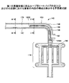
図2は、第1の実施形態に係るループ型ヒートパイプの蒸発器及びその周囲の断面図である。図1及び図2に示すように、蒸発器110には、例えば4つの貫通孔110xが形成されている。蒸発器110に形成された各貫通孔110xと回路基板10に形成された各貫通孔10xにボルト15を挿入し、回路基板10の下面側からナット16で止めることにより、蒸発器110と回路基板10とが固定される。
FIG. 2 is a cross-sectional view of the evaporator and its surroundings of the loop heat pipe according to the first embodiment. As shown in FIGS. 1 and 2, the
回路基板10には、例えば、CPU等の発熱部品12がバンプ11により実装され、発熱部品12の上面が蒸発器110の下面と密着する。蒸発器110内の作動流体Cは、発熱部品12で発生した熱により気化し、蒸気Cvが生成される。
A heat-
図1に示すように、蒸発器110に生成された蒸気Cvは、蒸気管130を通って凝縮器120に導かれ、凝縮器120において液化する。これにより、発熱部品12で発生した熱が凝縮器120に移動し、発熱部品12の温度上昇が抑制される。凝縮器120で液化した作動流体Cは、液管140を通って蒸発器110に導かれる。蒸気管130の幅W1は、例えば、8mm程度とすることができる。また、液管140の幅W2は、例えば、6mm程度とすることができる。蒸気管130の幅W1や液管140の幅W2は、これに限らず、例えば互いに等しくてもよい。
As shown in FIG. 1, vapor Cv generated in
作動流体Cの種類は特に限定されないが、蒸発潜熱によって発熱部品12を効率的に冷却するために、蒸気圧が高く、かつ蒸発潜熱が大きい流体を使用することが好ましい。そのような流体としては、例えば、アンモニア、水、フロン、アルコール、及びアセトンを挙げることができる。
Although the type of the working fluid C is not particularly limited, it is preferable to use a fluid with high vapor pressure and large latent heat of vaporization in order to efficiently cool the heat-generating
蒸発器110、凝縮器120、蒸気管130、及び液管140は、例えば、金属層が複数積層された構造とすることができる(図4及び図5参照)。金属層は、例えば、熱伝導性に優れた銅層であって、固相接合等により互いに直接接合されている。金属層の各々の厚さは、例えば、50μm~200μm程度とすることができる。
The
なお、金属層は銅層には限定されず、ステンレス層やアルミニウム層、マグネシウム合金層等から形成してもよい。また、金属層の積層数は特に限定されない。 The metal layer is not limited to a copper layer, and may be formed of a stainless steel layer, an aluminum layer, a magnesium alloy layer, or the like. Also, the number of stacked metal layers is not particularly limited.
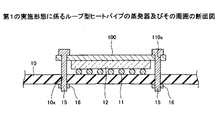
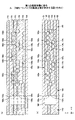
図3は、第1の実施形態に係るループ型ヒートパイプの注入口141及びその近傍における液管140の内部の構成を例示する平面模式図である。但し、図3では、一方の最外層となる金属層(図4及び図5に示す金属層151)の図示が省略されている。
FIG. 3 is a schematic plan view illustrating the internal configuration of the
図3に示すように、注入口141の近傍において、液管140内に、その内側の管壁142に接触するようにして多孔質体150が設けられている。例えば、多孔質体150は、管壁142に接触して、一体的に形成されている。多孔質体150は、液相の作動流体Cを貯留する。液管140に沿う方向において、多孔質体150の一方の端部150Aは、注入口141と蒸発器110との間に位置し、多孔質体150の他方の端部150Bは、注入口141と凝縮器120との間に位置する。
As shown in FIG. 3, a
注入口141より凝縮器120側において、多孔質体150は、液管140の外側の管壁143から離間しており、多孔質体150と管壁143との間に連絡流路180が形成されている。連絡流路180は注入口141に連通している。多孔質体150と連絡流路180との間には、ソリッドな支柱160が設けられている。
On the
液管140の多孔質体150の端部150Bと凝縮器120との間には、管壁142、管壁143、一方の最外層となる金属層(図4及び図5に示す金属層151)及び他方の最外層となる金属層(図4及び図5に示す金属層156)により囲まれた空間からなる流路170が存在する。流路170は流路101の一部である。連絡流路180は流路170に連通しており、注入口141から液管140に注入された液相の作動流体Cが、連絡流路180を通じて流路170に流れ込む。
Between the
注入口141より蒸発器110側では、多孔質体150は内側の管壁142だけでなく、外側の管壁143にも接触している。そして、多孔質体150は、注入口141と蒸発器110との間の少なくとも一部で、液管140の内部を充填している。
On the
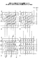
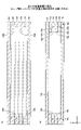
ここで、液管140、多孔質体150、支柱160、流路170及び連絡流路180について詳細に説明する。図4及び図5は、第1の実施形態に係るループ型ヒートパイプの内部の構成を例示する断面図である。図4は、図3中のI-I線に沿った断面図に相当し、図5は、図3中のII-II線に沿った断面図に相当する。図6は、2層目から5層目までの各金属層における多孔質体150に含まれる有底孔の配置を例示する平面図である。図6においてI-I線で示す部分が、図4中の多孔質体150の断面に相当する。なお、図3中の直線状のI-I線のうち、多孔質体150の部分での実際のI-I線は図6に示す通りである。
Here, the
液管140、多孔質体150及び支柱160は、例えば、金属層151~156の6層が積層された構造とすることができる。金属層151~156は、例えば、熱伝導性に優れた銅層であって、固相接合等により互いに直接接合されている。金属層151~156の各々の厚さは、例えば、50μm~200μm程度とすることができる。なお、金属層151~156は銅層には限定されず、ステンレス層やアルミニウム層、マグネシウム合金層等から形成してもよい。また、金属層の積層数は限定されず、5層以下や7層以上の金属層を積層してもよい。
The
なお、図4~図6において、金属層151~156の積層方向をZ方向、Z方向に垂直な平面内で液管140に沿う方向をY方向、この平面内においてY方向と直交する方向をX方向としている(以降の図も同様)。
4 to 6, the direction in which the metal layers 151 to 156 are laminated is the Z direction, the direction along the
液管140、多孔質体150及び支柱160において、1層目(一方の最外層)の金属層151及び6層目(他方の最外層)の金属層156には、孔や溝は形成されていない。これに対して、図4及び図6(a)に示すように、2層目の金属層152には、多孔質体150内で、上面側から厚さ方向の略中央部にかけて窪む有底孔152xと、下面側から厚さ方向の略中央部にかけて窪む有底孔152yとが、それぞれ複数個形成されている。
In the
有底孔152xと有底孔152yとは、平面視でX方向に交互に配置されている。また、有底孔152xと有底孔152yとは、平面視でY方向に交互に配置されている。X方向に交互に配置された有底孔152xと有底孔152yとは、平面視で部分的に重複しており、重複する部分は連通して細孔152zを形成している。Y方向に交互に配置された有底孔152xと有底孔152yとは、所定間隔を有して形成されており、平面視で重複していない。そのため、Y方向に交互に配置された有底孔152xと有底孔152yとは、細孔を形成していない。しかし、これに限らず、Y方向における有底孔152xと有底孔152yの配置は、平面視で重複し、細孔を形成してもよい。
The bottomed
有底孔152x及び152yは、例えば、直径が100μm~300μm程度の円形とすることができるが、楕円形や多角形等の任意の形状として構わない。有底孔152x及び152yの深さは、例えば、金属層152の厚さの半分程度とすることができる。隣接する有底孔152xの間隔L1は、例えば、100μm~400μm程度とすることができる。隣接する有底孔152yの間隔L2は、例えば、100μm~400μm程度とすることができる。
The bottomed
有底孔152x及び152yの内壁は、底面側から開口側に向かって拡幅するテーパ形状とすることができる。しかし、これに限らず、有底孔152x及び152yの内壁は、底面に対して垂直であっても構わない。また、有底孔152x及び152yの内壁は、湾曲する半円形状でも構わない。細孔152zの短手方向の幅W3は、例えば、10μm~50μm程度とすることができる。また、細孔152zの長手方向の幅W4は、例えば、50μm~150μm程度とすることができる。
The inner walls of the bottomed
図4に示すように、金属層152には、連絡流路180を構成する開口部152sも形成されている。開口部152sは、金属層152を厚さ方向(Z方向)に貫通する貫通孔で形成されている。この貫通孔は、例えば平面視で重複する上面側の有底孔と下面側の有底孔とが繋がって構成される。
As shown in FIG. 4 , the
図5に示すように、金属層152には、流路170を構成する開口部152tも形成されている。開口部152tは、金属層152を厚さ方向(Z方向)に貫通する貫通孔で形成されている。この貫通孔も、例えば平面視で重複する上面側の有底孔と下面側の有底孔とが繋がって構成される。
As shown in FIG. 5, the
図4及び図6(b)に示すように、3層目の金属層153には、多孔質体150内で、上面側から厚さ方向の略中央部にかけて窪む有底孔153xと、下面側から厚さ方向の略中央部にかけて窪む有底孔153yとが、それぞれ複数個形成されている。
As shown in FIGS. 4 and 6(b), the
金属層153では、有底孔153xのみがX方向に配置された列と、有底孔153yのみがX方向に配置された列とが、Y方向に交互に配置されている。Y方向に交互に配置された列において、隣接する列の有底孔153xと有底孔153yとは、平面視で部分的に重複しており、重複する部分は連通して細孔153zを形成している。
In the
但し、細孔153zを形成する隣接する有底孔153xと有底孔153yとは、中心位置がX方向にずれている。言い換えれば、細孔153zを形成する有底孔153xと有底孔153yとは、X方向及びY方向に対して斜め方向に交互に配置されている。有底孔153x及び153y、細孔153zの形状等は、例えば、有底孔152x及び152y、細孔152zの形状等と同様とすることができる。
However, the center positions of the adjacent bottomed
金属層152の有底孔152yと、金属層153の有底孔153xとは、平面視で重複する位置に形成されている。そのため、金属層152と金属層153との界面には、細孔は形成されない。しかし、これに限らず、X方向及びY方向において、有底孔153xと有底孔153yの配置を適宜変更することで、金属層152と金属層153との界面には、細孔を形成してもよい。
The bottomed
図4に示すように、金属層153には、連絡流路180を構成する開口部153sも形成されている。開口部153sは、金属層153を厚さ方向(Z方向)に貫通する貫通孔で形成されている。この貫通孔は、例えば平面視で重複する上面側の有底孔と下面側の有底孔とが繋がって構成される。
As shown in FIG. 4, the
図5に示すように、金属層153には、流路170を構成する開口部153tも形成されている。開口部153tは、金属層153を厚さ方向(Z方向)に貫通する貫通孔で形成されている。この貫通孔も、例えば平面視で重複する上面側の有底孔と下面側の有底孔とが繋がって構成される。
As shown in FIG. 5, the
図4及び図6(c)に示すように、4層目の金属層154には、多孔質体150内で、上面側から厚さ方向の略中央部にかけて窪む有底孔154xと、下面側から厚さ方向の略中央部にかけて窪む有底孔154yとが、それぞれ複数個形成されている。
As shown in FIGS. 4 and 6(c), the
有底孔154xと有底孔154yとは、平面視でX方向に交互に配置されている。また、有底孔154xと有底孔154yとは、平面視でY方向に交互に配置されている。X方向に交互に配置された有底孔154xと有底孔154yとは、平面視で部分的に重複しており、重複する部分は連通して細孔154zを形成している。Y方向に交互に配置された有底孔154xと有底孔154yとは、所定間隔を有して形成されており、平面視で重複していない。そのため、Y方向に交互に配置された有底孔154xと有底孔154yとは、細孔を形成していない。しかし、これに限らず、Y方向における有底孔154x及び154yの配置は、平面視で重複して、細孔を形成してもよい。有底孔154x及び154y、細孔154zの形状等は、例えば、有底孔152x及び152y、細孔152zの形状等と同様とすることができる。
The bottomed
金属層153の有底孔153yと、金属層154の有底孔154xとは、平面視で重複する位置に形成されている。そのため、金属層153と金属層154との界面には、細孔は形成されない。しかし、これに限らず、X方向及びY方向において、有底孔154xと有底孔154yの配置を適宜変更することで、金属層153と金属層154との界面には、細孔を形成してもよい。
The bottomed
図4に示すように、金属層154には、連絡流路180を構成する開口部154sも形成されている。開口部154sは、金属層154を厚さ方向(Z方向)に貫通する貫通孔で形成されている。この貫通孔は、例えば平面視で重複する上面側の有底孔と下面側の有底孔とが繋がって構成される。
As shown in FIG. 4 , the
図5に示すように、金属層154には、流路170を構成する開口部154tも形成されている。開口部154tは、金属層154を厚さ方向(Z方向)に貫通する貫通孔で形成されている。この貫通孔も、例えば平面視で重複する上面側の有底孔と下面側の有底孔とが繋がって構成される。
As shown in FIG. 5, the
図4及び図6(d)に示すように、5層目の金属層155には、多孔質体150内で、上面側から厚さ方向の略中央部にかけて窪む有底孔155xと、下面側から厚さ方向の略中央部にかけて窪む有底孔155yとが、それぞれ複数個形成されている。
As shown in FIGS. 4 and 6(d), the
金属層155では、有底孔155xのみがX方向に配置された列と、有底孔155yのみがX方向に配置された列とが、Y方向に交互に配置されている。Y方向に交互に配置された列において、隣接する列の有底孔155xと有底孔155yとは、平面視で部分的に重複しており、重複する部分は連通して細孔155zを形成している。
In the
但し、細孔155zを形成する隣接する有底孔155xと有底孔155yとは、中心位置がX方向にずれている。言い換えれば、細孔155zを形成する有底孔155xと有底孔155yとは、X方向及びY方向に対して斜め方向に交互に配置されている。有底孔155x及び155y、細孔155zの形状等は、例えば、有底孔152x及び152y、細孔152zの形状等と同様とすることができる。
However, the center positions of the adjacent bottomed
金属層154の有底孔154yと、金属層155の有底孔155xとは、平面視で重複する位置に形成されている。そのため、金属層154と金属層155との界面には、細孔は形成されない。しかし、これに限らず、X方向及びY方向において、有底孔155x及び有底孔155yの配置を適宜変更することで、金属層154と金属層155との界面には、細孔を形成してもよい。
The bottomed
図4に示すように、金属層155には、連絡流路180を構成する開口部155sも形成されている。開口部155sは、金属層155を厚さ方向(Z方向)に貫通する貫通孔で形成されている。この貫通孔は、例えば平面視で重複する上面側の有底孔と下面側の有底孔とが繋がって構成される。
As shown in FIG. 4 , the
図5に示すように、金属層155には、流路170を構成する開口部155tも形成されている。開口部155tは、金属層155を厚さ方向(Z方向)に貫通する貫通孔で形成されている。この貫通孔も、例えば平面視で重複する上面側の有底孔と下面側の有底孔とが繋がって構成される。
As shown in FIG. 5, the
各金属層に形成された細孔同士は互いに連通しており、互いに連通する細孔は多孔質体150内に三次元的に広がっている。そのため、作動流体Cは、毛細管力により、互いに連通する細孔内を三次元的に広がる。
The pores formed in each metal layer communicate with each other, and the pores that communicate with each other extend three-dimensionally within the
また、図4に示すように、開口部152s~155sは平面視で重複する位置に形成されており、開口部152s~155sから連絡流路180が構成されている。連絡流路180と多孔質体150との間の部分では、金属層152~155に孔や溝が形成されておらず、このような孔や溝が形成されていない部分が重なり合うことでソリッドな支柱160が形成されている。
In addition, as shown in FIG. 4, the
また、図5に示すように、平面視で、開口部152t~155tはX方向で交互にずれるようにして形成されている。すなわち、X方向において開口部153t及び155tが開口部152t及び154tよりも大きく形成され、管壁142及び143の両側で開口部153t及び155tの側面が開口部152t及び154tの側面よりも後退して凹んでいる。このように、開口部153t及び155tの側面のX方向の位置と開口部152t及び154tの側面のX方向の位置にずれがあり、金属層153に溝193が形成され、金属層155に溝195が形成されている。例えば、溝193及び195は、液管140に沿って延びる(Y方向において、流路170と略平行に延びる)ように形成されている。
Further, as shown in FIG. 5, the
このように、液管140の壁面(管壁142及び管壁143の壁面)には溝193及び195が設けられており、液管140の流路170内の液相の作動流体Cは、溝193及び195に生じる毛細管力によって凝縮器120から蒸発器110に向かって誘導される。
Thus,
また、注入口141の近傍にて流路170と蒸発器110との間に多孔質体150が設けられている。従って、注入口141から液管140内に注入された液相の作動流体Cは多孔質体150により、吸収されて貯留される。また、ループ型ヒートパイプ100が動作を開始した後では、溝193及び195により蒸発器110に向かって誘導されてきた液相の作動流体Cが、蒸発器110に達する前に多孔質体150により吸収されて、貯留される。
A
蒸発器110に付与される熱量が大きくなると、蒸発器110が蒸気Cvを生成する速度が、凝縮器120が蒸気Cvを液化して液相の作動流体Cを生成する速度を上回ることがある。このような場合、流路170内の液相の作動流体Cの量が減少していく。しかし、第1の実施形態では、流路170よりも蒸発器110側に位置する多孔質体150が液相の作動流体Cを貯留しているため、流路170内の液相の作動流体Cの量が減少したとしても、多孔質体150から蒸発器110に液相の作動流体Cを供給し続けることができる。つまり、第1の実施形態によれば、液管140内の作動流体Cの枯渇に伴うドライアウトを抑制することができる。
As the amount of heat imparted to
また、ループ型ヒートパイプ100の使用時等において、凝縮器120が蒸発器110の鉛直下方に位置すると、作動流体Cを凝縮器120側に移動させる重力が作用する。しかし、第1の実施形態では、多孔質体150が作動流体Cを貯留しているため、多孔質体150から蒸発器110に液相の作動流体Cを供給し続け、ドライアウトを抑制することができる。
Further, when the
また、蒸発器110からのヒートリーク等によって液管140内を蒸気Cvが逆流しようとしても、多孔質体150から液相の作動流体Cに作用する毛細管力で蒸気Cvを押し戻すことができ、蒸気Cvの逆流を防止することが可能となる。特に、多孔質体150の一部が蒸発器110の近傍で液管140の内部を充填している場合、蒸気Cvの逆流を防止する効果が高い。
In addition, even if the vapor Cv tries to flow back in the
更に、多孔質体150は蒸発器110内にも設けられている。蒸発器110内の多孔質体150のうち、液管140寄りの部分には液相の作動流体Cが浸透する。この際、多孔質体150から作動流体Cに作用する毛細管力が、ループ型ヒートパイプ100内で作動流体Cを循環させるポンピング力となる。
Furthermore, the
しかも、この毛細管力は蒸発器110内の蒸気Cvに対抗するため、蒸気Cvが液管140に逆流するのを抑制することが可能となる。
Moreover, since this capillary force opposes the steam Cv in the
なお、液管140には作動流体Cを注入するための注入口141が形成されているが、注入口141は塞がれており、ループ型ヒートパイプ100内は気密に保たれる。
An
[ループ型ヒートパイプの製造方法]
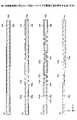
次に、第1の実施形態に係るループ型ヒートパイプの製造方法について、多孔質体の製造工程を中心に説明する。図7~図10は、第1の実施形態に係るループ型ヒートパイプの製造工程を例示する図である。図7~図8は、図4に対応する断面を示し、図9~図10は、図5に対応する断面を示している。
[Manufacturing method of loop heat pipe]
Next, the manufacturing method of the loop heat pipe according to the first embodiment will be described, centering on the manufacturing process of the porous body. 7 to 10 are diagrams illustrating the manufacturing process of the loop heat pipe according to the first embodiment. 7 to 8 show cross sections corresponding to FIG. 4, and FIGS. 9 to 10 show cross sections corresponding to FIG.
まず、図7(a)及び図9(a)に示す工程では、図1の平面形状に形成された金属シート152bを準備する。そして、金属シート152bの上面にレジスト層310を形成し、金属シート152bの下面にレジスト層320を形成する。金属シート152bは、最終的に金属層152となる部材であり、例えば、銅、ステンレス、アルミニウム、マグネシウム合金等から形成することができる。金属シート152bの厚さは、例えば、50μm~200μm程度とすることができる。レジスト層310及び320としては、例えば、感光性のドライフィルムレジスト等を用いることができる。
First, in the steps shown in FIGS. 7A and 9A, a
次に、図7(b)及び図9(b)に示す工程では、金属シート152bの多孔質体150を形成する領域において、レジスト層310を露光及び現像して、金属シート152bの上面を選択的に露出する開口部310xを形成する。また、レジスト層320を露光及び現像して、金属シート152bの下面を選択的に露出する開口部320xを形成する。開口部310x及び320xの形状及び配置は、図9(a)に示した有底孔152x及び152yの形状及び配置に対応するように形成する。
Next, in the steps shown in FIGS. 7B and 9B, the resist
レジスト層310の露光及び現像の際には、図7(b)に示すように、連絡流路180を形成する領域において、金属シート152bの上面を選択的に露出する開口部310yも形成し、図9(b)に示すように、流路170を形成する領域において、金属シート152bの上面を選択的に露出する開口部310zも形成する。また、レジスト層320の露光及び現像の際には、図7(b)に示すように、連絡流路180を形成する領域において、金属シート152bの下面を選択的に露出する開口部320yも形成し、図9(b)に示すように、流路170を形成する領域において、金属シート152bの下面を選択的に露出する開口部320zも形成する。
During exposure and development of the resist
次に、図7(c)及び図9(c)に示す工程では、開口部310x、310y及び310z内に露出する金属シート152bを金属シート152bの上面側からハーフエッチングすると共に、開口部320x、320y及び320z内に露出する金属シート152bを金属シート152bの下面側からハーフエッチングする。これにより、金属シート152bの上面側に有底孔152xが形成され、下面側に有底孔152yが形成されると共に、金属シート152bを貫通する開口部152s及び152tが形成される。また、表裏でX方向に交互に配置された開口部310xと開口部320xとは、平面視で部分的に重複しているため、重複する部分が連通して細孔152zが形成される。金属シート152bのハーフエッチングには、例えば、塩化第二鉄溶液を用いることができる。
Next, in the steps shown in FIGS. 7C and 9C, the
次に、図7(d)及び図9(d)に示す工程では、レジスト層310及び320を剥離液により剥離する。これにより、金属層152が完成する。
Next, in steps shown in FIGS. 7D and 9D, the resist
次に、図8(a)及び図10(a)に示す工程では、孔や溝が形成されていないベタ状の金属層151及び156を準備する。また、金属層152と同様の方法により、金属層153、154、及び155を形成する。金属層153、154、及び155に形成される有底孔、細孔及び開口部の位置は、例えば、図6に示した通りである。
Next, in the steps shown in FIGS. 8A and 10A,
次に、図8(b)及び図10(b)に示す工程では、図8(a)及び図10(a)に示す順番で各金属層を積層し、加圧及び加熱により固相接合を行う。これにより、隣接する金属層同士が直接接合され、蒸発器110、凝縮器120、蒸気管130、及び液管140が形成され、蒸発器110及び液管140に多孔質体150が形成され、液管140に支柱160が形成される。また、多孔質体150の端部150Bの凝縮器120側に、作動流体Cを多孔質体150に誘導する空間からなる微細な流路170が形成されると共に、液管140の外側の管壁143と支柱160との間に連絡流路180が形成される。
Next, in the steps shown in FIGS. 8B and 10B, each metal layer is laminated in the order shown in FIGS. conduct. As a result, the adjacent metal layers are directly bonded to form the
その後、真空ポンプ等を用いて液管140内を排気した後、注入口141から液管140内に作動流体Cを注入する。液管140内に注入された作動流体Cは、多孔質体150に浸み込むと共に、連絡流路180を通じて流路170に流れ込む。このとき、多孔質体150と連絡流路180との間にソリッドな支柱160が設けられているため、多孔質体150が連絡流路180に面している場合よりも、作動流体Cは流路170まで流れやすい。作動流体Cの注入後には、注入口141を塞ぐ。
Thereafter, after the inside of the
ここで、固相接合とは、接合対象物同士を溶融させることなく固相(固体)状態のまま加熱して軟化させ、更に加圧して塑性変形を与えて接合する方法である。なお、固相接合によって隣接する金属層同士を良好に接合できるように、金属層151~156の全ての材料を同一にすることが好ましい。 Here, solid phase bonding is a method in which objects to be bonded are heated and softened in a solid phase (solid) state without being melted, and are further pressurized to give plastic deformation and bond. In addition, it is preferable to use the same material for all the metal layers 151 to 156 so that adjacent metal layers can be well bonded by solid phase bonding.
このようにして、ループ型ヒートパイプ100を製造することができる。
Thus, the
このように、各金属層の両面側から形成した有底孔を部分的に連通させて各金属層内に細孔を設ける構造とすることで、貫通孔が形成された金属層同士を貫通孔が部分的に重複するように積層する従来の細孔の形成方法よりも優れた安定性を得ることができる。すなわち、金属層同士を積層する際の位置ずれや、金属層を複数積層する際の加熱処理の際の金属層の膨張及び収縮による位置ずれが生じることがなく、一定の大きさの細孔を金属層内に形成できる。 In this way, by forming a structure in which the bottomed holes formed from both sides of each metal layer are partially communicated with each other to provide a hole in each metal layer, the metal layers in which the through holes are formed can be separated from each other. It is possible to obtain better stability than the conventional method of forming pores in which the layers are partially overlapped. That is, there is no misalignment when laminating metal layers, or misalignment due to expansion and contraction of metal layers during heat treatment when laminating a plurality of metal layers, and pores of a certain size are formed. It can be formed in a metal layer.
これにより、細孔の大きさがばらついて細孔により発現する毛細管力が低下することを防止可能となり、蒸発器110から液管140に蒸気Cvが逆流することを抑制する効果を安定的に得ることができる。
As a result, it is possible to prevent the deterioration of the capillary force generated by the pores due to variations in the size of the pores, and to stably obtain the effect of suppressing the reverse flow of the vapor Cv from the
また、金属層同士を積層する部分では、隣接する有底孔全体を重複させる構造とすることで、金属層同士が接する面積を大きくできるため、強固な接合が可能となる。 In addition, in the portion where the metal layers are laminated, by forming a structure in which the entire adjacent bottomed holes are overlapped, the area where the metal layers contact each other can be increased, so that strong bonding can be achieved.
更に、この製造方法によれば、多孔質体150を構成する有底孔及び細孔と流路170及び連絡流路180を構成する貫通孔とを並行して形成することができる。
Furthermore, according to this manufacturing method, the bottomed holes and pores forming the
(第1の実施形態の変形例)
次に、第1の実施形態の変形例について説明する。第1の実施形態の変形例は、連絡流路180の構成の点で第1の実施形態と相違する。図11は、第1の実施形態の変形例に係るループ型ヒートパイプの内部の構成を例示する断面図である。図11は、図3中のI-I線に沿った断面図に相当する。
(Modification of the first embodiment)
Next, a modification of the first embodiment will be described. The modification of the first embodiment differs from the first embodiment in the configuration of the
第1の実施形態の変形例に係るループ型ヒートパイプは、第1の実施形態に係るループ型ヒートパイプ100と同様に、液管140、多孔質体150、支柱160、流路170及び連絡流路180を有する。
Similar to the
但し、図11に示すように、平面視で、開口部152s~155sがX方向で交互にずれるようにして形成されている。すなわち、X方向において開口部153s及び155sが開口部152s及び154sよりも大きく形成され、管壁143及び支柱160の両側で開口部153s及び155sの側面が開口部152s及び154sの側面よりも後退して凹んでいる。このように、開口部153s及び155sの側面のX方向の位置と開口部152s及び154sの側面のX方向の位置にずれがあり、金属層153に溝293が形成され、金属層155に溝295が形成されている。例えば、溝293及び295は、液管140に沿って延びる(Y方向において、連絡流路180と略平行に延びる)ように形成されている。
However, as shown in FIG. 11, the
他の構成は第1の実施形態と同様である。 Other configurations are the same as those of the first embodiment.
このような変形例によっても第1の実施形態と同様の効果を得ることができる。また、連絡流路180の壁面に溝293及び295が形成されているため、溝293及び295によって液相の作動流体Cの流動が促進される。従って、注入口141から注入された作動流体Cをより速やかに流路170に導くことができる。
Such a modified example can also provide the same effects as the first embodiment. Further, since the
例えば、溝293は次のようにして有底孔153x及び153yと並行して形成することができる。すなわち、最終的に金属層153となる金属シートの上面及び下面に形成するレジスト層に、溝293に倣う平面形状の開口部を形成し、この金属シートのハーフエッチングを行う。このようにして有底孔153x及び153yと並行して溝293を形成することができる。溝293と同様に、例えば、溝295は有底孔155x及び155yと並行して形成することができる。
For example, groove 293 can be formed in parallel with bottomed
(第2の実施形態)
次に、第2の実施形態について説明する。第2の実施形態は、流路170及び連絡流路180の構成の点で第1の実施形態と相違する。図12及び図13は、第2の実施形態に係るループ型ヒートパイプの内部の構成を例示する断面図である。図12は、図3中のI-I線に沿った断面図に相当し、図13は、図3中のII-II線に沿った断面図に相当する。
(Second embodiment)
Next, a second embodiment will be described. The second embodiment differs from the first embodiment in the configuration of the
第2の実施形態に係るループ型ヒートパイプは、第1の実施形態に係るループ型ヒートパイプ100と同様に、液管140、多孔質体150、支柱160、流路170及び連絡流路180を有する。
Like the
但し、図12に示すように、支柱160及び管壁143の両側において、開口部152sの縁に、有底孔152xと同様に、上面側から厚さ方向の略中央部にかけて窪む溝492が形成されている。つまり、金属層152の上面に、連絡流路180に繋がるように溝492が形成されている。溝492の深さは、例えば、金属層152の厚さの半分程度とすることができる。
However, as shown in FIG. 12, on both sides of the
また、図12に示すように、支柱160及び管壁143の両側において、開口部153sの縁に、有底孔153xと同様に、上面側から厚さ方向の略中央部にかけて窪む溝493が形成されている。つまり、金属層153の上面に、連絡流路180に繋がるように溝493が形成されている。溝493の深さは、例えば、金属層153の厚さの半分程度とすることができる。
Further, as shown in FIG. 12, on both sides of the
また、図12に示すように、支柱160及び管壁143の両側において、開口部154sの縁に、有底孔154xと同様に、上面側から厚さ方向の略中央部にかけて窪む溝494が形成されている。つまり、金属層154の上面に、連絡流路180に繋がるように溝494が形成されている。溝494の深さは、例えば、金属層154の厚さの半分程度とすることができる。
Further, as shown in FIG. 12, on both sides of the
また、図12に示すように、支柱160及び管壁143の両側において、開口部155sの縁に、有底孔155xと同様に、上面側から厚さ方向の略中央部にかけて窪む溝495が形成されている。つまり、金属層155の上面に、連絡流路180に繋がるように溝495が形成されている。溝495の深さは、例えば、金属層155の厚さの半分程度とすることができる。
Further, as shown in FIG. 12,
溝492~495は、湾曲面からなる凹形状の内壁面を有する。また、図12では多孔質体150に含まれる有底孔の断面形状をテーパ形状としているが、これら有底孔も、湾曲面からなる凹形状の内壁面を有することができる。
The
開口部152s~155sは平面視で重複する位置に形成されている。また、例えば、溝492~495は、液管140に沿って延びる(Y方向において、連絡流路180と略平行に延びる)ように形成されている。
The
更に、第2の実施形態では、図13に示すように、多孔質体150の端部150Bと凝縮器120との間で、液管140の壁面に形成される溝が第1の実施形態と相違する。
Furthermore, in the second embodiment, as shown in FIG. 13, the groove formed in the wall surface of the
すなわち、図13に示すように、管壁142及び143の両側において、開口部152tの縁に、有底孔152xと同様に、上面側から厚さ方向の略中央部にかけて窪む溝392が形成されている。つまり、金属層152の上面に、流路170に繋がるように溝392が形成されている。溝392の深さは、例えば、金属層152の厚さの半分程度とすることができる。
That is, as shown in FIG. 13, on both sides of the
また、図13に示すように、管壁142及び143の両側において、開口部153tの縁に、有底孔153xと同様に、上面側から厚さ方向の略中央部にかけて窪む溝393が形成されている。つまり、金属層153の上面に、流路170に繋がるように溝393が形成されている。溝393の深さは、例えば、金属層153の厚さの半分程度とすることができる。
Further, as shown in FIG. 13, on both sides of the
また、図13に示すように、管壁142及び143の両側において、開口部154tの縁に、有底孔154xと同様に、上面側から厚さ方向の略中央部にかけて窪む溝394が形成されている。つまり、金属層154の上面に、流路170に繋がるように溝394が形成されている。溝394の深さは、例えば、金属層154の厚さの半分程度とすることができる。
Further, as shown in FIG. 13, on both sides of the
また、図13に示すように、管壁142及び143の両側において、開口部155tの縁に、有底孔155xと同様に、上面側から厚さ方向の略中央部にかけて窪む溝395が形成されている。つまり、金属層155の上面に、流路170に繋がるように溝395が形成されている。溝395の深さは、例えば、金属層155の厚さの半分程度とすることができる。
Further, as shown in FIG. 13, on both sides of the
溝392~395は、湾曲面からなる凹形状の内壁面を有する。また、これに限らず、図12の多孔質体150に含まれる有底孔の断面形状のようにテーパ形状でもよい。
The
開口部152t~155tは平面視で重複する位置に形成されている。また、例えば、溝392~395は、液管140に沿って延びる(Y方向において、流路170と略平行に延びる)ように形成されている。
The
他の構成は第1の実施形態と同様である。 Other configurations are the same as those of the first embodiment.
第2の実施形態によっても第1の実施形態と同様の効果を得ることができる。また、流路170の壁面に溝392~395が形成されているため、溝392~395によって液相の作動流体Cの流動が促進される。溝の数が第1の実施形態より多いため、熱輸送性能をより一層向上することができる。
Effects similar to those of the first embodiment can also be obtained by the second embodiment. Further, since the
また、連絡流路180の壁面に溝492~495が形成されているため、溝492~495によって液相の作動流体Cの流動が促進される。溝の数が第1の実施形態の第1の参考例より多いため、注入口141から注入された作動流体Cをより速やかに流路170に導くことができる。
Further, since the
例えば、溝392及び492は次のようにして有底孔152xと並行して形成することができる。すなわち、金属シート152bに形成するレジスト層310に形成する開口部310z(図9(b)参照)及び開口部310y(図7(b)参照)の平面形状を、溝392、492の形状に倣ったものとする。そして、金属シート152bのハーフエッチングを行う。このようにして有底孔152xと並行して溝392及び492を形成することができる。溝392及び492と同様に、例えば、溝393~395及び493~495は有底孔153x~155xと並行して形成することができる。
For example,
なお、第1の実施形態と同様に、連絡流路180の壁面に溝492~495が形成されていなくてもよい。また、第1の実施形態の変形例と同様に、溝492~495に代えて、連絡流路180の壁面に溝293及び295が形成されていてもよい。
Note that the
(第3の実施形態)
次に、第3の実施形態について説明する。第3の実施形態は、流路170及び連絡流路180の構成の点で第1の実施形態と相違する。図14及び図15は、第3の実施形態に係るループ型ヒートパイプの内部の構成を例示する断面図である。図14は、図3中のI-I線に沿った断面図に相当し、図15は、図3中のII-II線に沿った断面図に相当する。
(Third embodiment)
Next, a third embodiment will be described. The third embodiment differs from the first embodiment in the configuration of the
第3の実施形態に係るループ型ヒートパイプは、第2の実施形態に係るループ型ヒートパイプ100と同様に、液管140、多孔質体150、支柱160、流路170及び連絡流路180を有する。
Like the
但し、図14に示すように、支柱160及び管壁143の両側において、開口部152sの縁に、溝492だけでなく、有底孔152yと同様に、下面側から厚さ方向の略中央部にかけて窪む溝692が形成されている。つまり、金属層152の下面に、連絡流路180に繋がるように溝692が形成されている。溝692の深さは、例えば、金属層152の厚さの半分程度とすることができる。
However, as shown in FIG. 14, on both sides of the
また、図14に示すように、支柱160及び管壁143の両側において、開口部153sの縁に、溝493だけでなく、有底孔153yと同様に、下面側から厚さ方向の略中央部にかけて窪む溝693が形成されている。つまり、金属層153の下面に、連絡流路180に繋がるように溝693が形成されている。溝693の深さは、例えば、金属層153の厚さの半分程度とすることができる。
In addition, as shown in FIG. 14, on both sides of the
また、図14に示すように、支柱160及び管壁143の両側において、開口部154sの縁に、溝494だけでなく、有底孔154yと同様に、下面側から厚さ方向の略中央部にかけて窪む溝694が形成されている。つまり、金属層154の下面に、連絡流路180に繋がるように溝694が形成されている。溝694の深さは、例えば、金属層154の厚さの半分程度とすることができる。
As shown in FIG. 14, on both sides of the
また、図14に示すように、支柱160及び管壁143の両側において、開口部155sの縁に、溝495だけでなく、有底孔155yと同様に、下面側から厚さ方向の略中央部にかけて窪む溝695が形成されている。つまり、金属層155の下面に、連絡流路180に繋がるように溝695が形成されている。溝695の深さは、例えば、金属層155の厚さの半分程度とすることができる。
Further, as shown in FIG. 14, on both sides of the
溝692と溝493とが繋がって溝892が形成され、溝693と溝494とが繋がって溝893が形成され、溝694と溝495とが繋がって溝894が形成されている。
The
更に、図14に示すように、支柱160及び管壁143の両側において、溝492と繋がるようにして、金属層151に、下面側から厚さ方向の略中央部にかけて窪む溝691が形成されている。つまり、金属層151の下面に、連絡流路180に繋がるように溝691が形成されている。溝691の深さは、例えば、金属層151の厚さの半分程度とすることができる。溝691と溝492とが繋がって溝891が形成されている。
Furthermore, as shown in FIG. 14,
更に、図14に示すように、支柱160及び管壁143の両側において、溝695と繋がるようにして、金属層156に、上面側から厚さ方向の略中央部にかけて窪む溝496が形成されている。つまり、金属層156の上面に、連絡流路180に繋がるように溝496が形成されている。溝496の深さは、例えば、金属層156の厚さの半分程度とすることができる。溝695と溝496とが繋がって溝895が形成されている。
Furthermore, as shown in FIG. 14,
溝691~695及び496は、湾曲面からなる凹形状の内壁面を有する。また、図14では多孔質体150に含まれる有底孔の断面形状をテーパ形状としているが、これら多孔質体150に含まれる有底孔も、湾曲面からなる凹形状の内壁面を有することができる。
The
第2の実施形態と同様に、開口部152s~155sは平面視で重複する位置に形成されている。また、例えば、溝891~895は、液管140に沿って延びる(Y方向において、連絡流路180と略平行に延びる)ように形成されている。
As in the second embodiment, the
更に、第3の実施形態では、図15に示すように、多孔質体150の端部150Bと凝縮器120との間で、液管140の壁面に形成される溝が第2の実施形態と相違する。
Furthermore, in the third embodiment, as shown in FIG. 15, the groove formed in the wall surface of the
すなわち、図15に示すように、管壁142及び143の両側において、開口部152tの縁に、溝392だけでなく、有底孔152yと同様に、下面側から厚さ方向の略中央部にかけて窪む溝592が形成されている。つまり、金属層152の下面に、流路170に繋がるように溝592が形成されている。溝592の深さは、例えば、金属層152の厚さの半分程度とすることができる。
That is, as shown in FIG. 15, on both sides of the
また、図15に示すように、管壁142及び143の両側において、開口部153tの縁に、溝393だけでなく、有底孔153yと同様に、下面側から厚さ方向の略中央部にかけて窪む溝593が形成されている。つまり、金属層153の下面に、流路170に繋がるように溝593が形成されている。溝593の深さは、例えば、金属層153の厚さの半分程度とすることができる。
Further, as shown in FIG. 15, on both sides of the
また、図15に示すように、管壁142及び143の両側において、開口部154tの縁に、溝394だけでなく、有底孔154yと同様に、下面側から厚さ方向の略中央部にかけて窪む溝594が形成されている。つまり、金属層154の下面に、流路170に繋がるように溝594が形成されている。溝594の深さは、例えば、金属層154の厚さの半分程度とすることができる。
Further, as shown in FIG. 15, on both sides of the
また、図15に示すように、管壁142及び143の両側において、開口部155tの縁に、溝395だけでなく、有底孔155yと同様に、下面側から厚さ方向の略中央部にかけて窪む溝595が形成されている。つまり、金属層155の下面に、流路170に繋がるように溝595が形成されている。溝595の深さは、例えば、金属層155の厚さの半分程度とすることができる。
Further, as shown in FIG. 15, on both sides of the
溝592と溝393とが繋がって溝792が形成され、溝593と溝394とが繋がって溝793が形成され、溝594と溝395とが繋がって溝794が形成されている。
The
更に、図15に示すように、管壁142及び143の両側において、溝392と繋がるようにして、金属層151に、下面側から厚さ方向の略中央部にかけて窪む溝591が形成されている。つまり、金属層151の下面に、流路170に繋がるように溝591が形成されている。溝591の深さは、例えば、金属層151の厚さの半分程度とすることができる。溝591と溝392とが繋がって溝791が形成されている。
Furthermore, as shown in FIG. 15, grooves 591 are formed in the
更に、図15に示すように、管壁142及び143の両側において、溝595と繋がるようにして、金属層156に、上面側から厚さ方向の略中央部にかけて窪む溝396が形成されている。つまり、金属層156の上面に、流路170に繋がるように溝396が形成されている。溝396の深さは、例えば、金属層156の厚さの半分程度とすることができる。溝595と溝396とが繋がって溝795が形成されている。
Furthermore, as shown in FIG. 15, on both sides of the
溝591~595及び396は、湾曲面からなる凹形状の内壁面を有する。また、これに限らず、図14の多孔質体150に含まれる有底孔の断面形状のようにテーパ形状でもよい。
The grooves 591 to 595 and 396 have concave inner wall surfaces made of curved surfaces. Also, the shape is not limited to this, and may be a tapered shape like the cross-sectional shape of the bottomed hole included in the
第2の実施形態と同様に、開口部152t~155tは平面視で重複する位置に形成されている。また、例えば、溝791~795は、液管140に沿って延びる(Y方向において、流路170と略平行に延びる)ように形成されている。
As in the second embodiment, the
他の構成は第2の実施形態と同様である。 Other configurations are similar to those of the second embodiment.
第3の実施形態によっても第2の実施形態と同様の効果を得ることができる。また、流路170の壁面に溝791~795が形成されているため、溝791~795によって液相の作動流体Cの流動が促進される。溝の数が第2の実施形態より多いため、熱輸送性能をより一層向上することができる。
Effects similar to those of the second embodiment can also be obtained by the third embodiment. Further, since the grooves 791 to 795 are formed in the wall surface of the
また、連絡流路180の壁面に溝891~895が形成されているため、溝891~895によって液相の作動流体Cの流動が促進される。溝の数が第2の実施形態より多いため、注入口141から注入された作動流体Cをより速やかに流路170に導くことができる。
Further, since the grooves 891 to 895 are formed on the wall surface of the
例えば、溝592及び692は次のようにして有底孔152yと並行して形成することができる。すなわち、金属シート152bに形成するレジスト層320に形成する開口部320z(図9(b)参照)及び開口部320y(図7(b)参照)の平面形状を、溝592、692の形状に倣ったものとする。そして、金属シート152bのハーフエッチングを行う。このようにして有底孔152yと並行して溝592及び692を形成することができる。溝592及び692と同様に、例えば、溝593~595及び693~695は有底孔153y~155yと並行して形成することができる。
For example,
また、金属層151及び156の溝591、691、396及び496も、金属層151及び156の溝591、691、396及び496の形成予定領域に開口部を備えたレジスト層を用いてハーフエッチングすることにより形成することができる。
Also, the
なお、いずれの実施形態においても、液管140内の多孔質体150は、内側の管壁142に接触している必要はなく、管壁142から離間していてもよい。また、注入口141と蒸発器110との間で、多孔質体150が液管140の内部を充填していなくてもよい。例えば、多孔質体150が外側の管壁143に接触せずに、管壁143から離間していてもよい。
In any embodiment, the
また、流路170内に多孔質体150の端部150Bに繋がり、液管140に沿って延びる(Y方向において、流路170と略平行に延びる)ソリッドな支柱が設けられていてもよい。ソリッドな支柱を含むことにより、厚さ方向(Z方向)の機械的強度を向上することができる。また、支柱の側面に溝が形成されていてもよい。このような溝は、溝193及び195等と同様に、液相の作動流体Cの流動を促進する。更に、多孔質体150が吸収しきれなかった作動流体Cを吸収し、液管140内での液相の作動流体Cの蒸発器110側から凝縮器120側への移動を遮る遮蔽体が液管140内に設けられていてもよい。遮蔽体としては、例えば、多孔質体150と同様に、金属層152~155に形成された有底孔及び細孔を備えた多孔質体を用いることができる。
Further, a solid support may be provided in the
また、液管140の、端部150Bよりも凝縮器120側に、凝縮器120により液化された作動流体Cを蒸発器110に向けて誘導する多孔質体が、多孔質体150から離間して設けられていてもよい。このような多孔質体は、例えば、管壁142及び143の近傍に設けることができる。
Further, a porous body that guides the working fluid C liquefied by the
また、多孔質体150の領域において、金属層151や金属層156に有底孔を形成してもよい。また、流路170の領域において、多孔質体150に貯留された作動流体Cを流路170側に浸み出させない範囲で、流路170に露出する金属層151や金属層156に有底孔を形成してもよい。金属層151や金属層156にも有底孔を形成することで、更に熱輸送性能をより一層向上することができる。
Also, bottomed holes may be formed in the
また、多孔質体150と連絡流路180との間に支柱160が設けられている必要はなく、多孔質体150が連絡流路180に面していてもよい。
Moreover, it is not necessary to provide the
また、多孔質体150を構成する孔が有底孔である必要はなく、多孔質体150に貫通孔が含まれていてもよい。
Moreover, the pores forming the
また、注入口141の位置は、多孔質体150の端部150Aと端部150Bとの間であればよく、例えば、図3に示す平面形状がL字型の液管140において、その屈曲部よりも凝縮器120側に注入口141が設けられていてもよい。
In addition, the position of the
以上、好ましい実施の形態等について詳説したが、上述した実施の形態等に制限されることはなく、特許請求の範囲に記載された範囲を逸脱することなく、上述した実施の形態等に種々の変形及び置換を加えることができる。 Although the preferred embodiments and the like have been described in detail above, the present invention is not limited to the above-described embodiments and the like, and various modifications can be made to the above-described embodiments and the like without departing from the scope of the claims. Modifications and substitutions can be made.
100 ループ型ヒートパイプ
110 蒸発器
120 凝縮器
130 蒸気管
140 液管
141 注入口
142、143 管壁
150 多孔質体
150A、150B 端部
160 支柱
170 流路
180 連絡流路
193、195、293、295、392~396、492~496、591~595、691~695、791~795、891~895 溝
REFERENCE SIGNS
Claims (7)
前記作動流体を液化する凝縮器と、
前記蒸発器と前記凝縮器とを接続する液管と、
前記蒸発器と前記凝縮器とを接続し、前記液管と共にループを形成する蒸気管と、
前記液管内に設けられ、液相の前記作動流体を貯留する多孔質体と、
を有し、
前記液管は、互いに積層された複数の金属層から形成され、
前記液管は、
第1管壁と、
前記複数の金属層の積層方向に垂直な方向で前記第1管壁に対向する第2管壁と、
を有し、
前記第1管壁と前記第2管壁との間にソリッドな支柱が設けられ、
前記支柱は、
前記第2管壁に対向する第1側面と、
前記第1管壁に対向する第2側面と、
を有し、
前記多孔質体は、前記第1管壁と前記第2側面との間に設けられ、
前記多孔質体は、
前記第1管壁に接触する第3側面と、
前記第2側面に接触する第4側面と、
を有し、
前記液管は、前記作動流体を注入するための注入口を有し、
前記注入口は、前記第2管壁に設けられ、
前記第1側面と前記第2管壁との間に連絡流路が設けられ、
前記多孔質体の一方の第1の端部は、前記注入口と前記蒸発器との間に位置し、
前記多孔質体の他方の第2の端部は、前記注入口と前記凝縮器との間に位置し、
前記多孔質体は、前記注入口と前記蒸発器との間の少なくとも一部で、前記液管の内部を充填することを特徴とするループ型ヒートパイプ。 an evaporator for vaporizing the working fluid;
a condenser that liquefies the working fluid;
a liquid pipe connecting the evaporator and the condenser;
a vapor pipe connecting the evaporator and the condenser and forming a loop with the liquid pipe;
a porous body that is provided in the liquid pipe and stores the liquid-phase working fluid;
has
the liquid tube is formed from a plurality of metal layers stacked together;
The liquid tube is
a first tube wall;
a second pipe wall facing the first pipe wall in a direction perpendicular to the stacking direction of the plurality of metal layers;
has
A solid strut is provided between the first tube wall and the second tube wall,
The strut is
a first side surface facing the second pipe wall;
a second side facing the first tube wall;
has
The porous body is provided between the first tube wall and the second side surface,
The porous body is
a third side surface in contact with the first tube wall;
a fourth side contacting the second side;
has
The liquid tube has an inlet for injecting the working fluid,
The injection port is provided in the second pipe wall,
A communication channel is provided between the first side surface and the second pipe wall,
one first end of the porous body is located between the inlet and the evaporator;
the other second end of the porous body is located between the inlet and the condenser;
The loop-type heat pipe, wherein the porous body fills the inside of the liquid pipe at least partially between the inlet and the evaporator.
前記連絡流路は、前記注入口と前記流路とを繋ぐことを特徴とする請求項1乃至3のいずれか1項に記載のループ型ヒートパイプ。 the liquid tube has a flow path formed of a space provided closer to the condenser than the second end,
4. The loop heat pipe according to any one of claims 1 to 3, wherein the connecting channel connects the inlet and the channel.
複数の金属層を積層することにより、前記蒸発器、前記凝縮器、前記液管及び前記蒸気管を形成すると共に、前記作動流体を注入するための注入口を前記液管に形成し、前記液管内に液相の前記作動流体を貯留する多孔質体を形成する工程を有し、
前記液管は、
第1管壁と、
前記複数の金属層の積層方向に垂直な方向で前記第1管壁に対向する第2管壁と、
を有し、
前記第1管壁と前記第2管壁との間にソリッドな支柱が設けられ、
前記支柱は、
前記第2管壁に対向する第1側面と、
前記第1管壁に対向する第2側面と、
を有し、
前記多孔質体は、前記第1管壁と前記第2側面との間に設けられ、
前記多孔質体は、
前記第1管壁に接触する第3側面と、
前記第2側面に接触する第4側面と、
を有し、
前記注入口は、前記第2管壁に設けられ、
前記第1側面と前記第2管壁との間に連絡流路が設けられ、
前記多孔質体の一方の第1の端部は、前記注入口と前記蒸発器との間に位置し、
前記多孔質体の他方の第2の端部は、前記注入口と前記凝縮器との間に位置し、
前記多孔質体は、前記注入口と前記蒸発器との間の少なくとも一部で、前記液管の内部を充填することを特徴とするループ型ヒートパイプの製造方法。 an evaporator that evaporates a working fluid; a condenser that liquefies the working fluid; a liquid pipe that connects the evaporator and the condenser; a liquid pipe that connects the evaporator and the condenser; A loop-type heat pipe manufacturing method comprising: a steam pipe forming a loop;
By laminating a plurality of metal layers, the evaporator, the condenser, the liquid pipe, and the steam pipe are formed, and an injection port for injecting the working fluid is formed in the liquid pipe, and the liquid is forming a porous body for storing the liquid-phase working fluid in the pipe;
The liquid tube is
a first tube wall;
a second pipe wall facing the first pipe wall in a direction perpendicular to the stacking direction of the plurality of metal layers;
has
A solid strut is provided between the first tube wall and the second tube wall,
The strut is
a first side surface facing the second pipe wall;
a second side facing the first tube wall;
has
The porous body is provided between the first tube wall and the second side surface,
The porous body is
a third side surface in contact with the first tube wall;
a fourth side contacting the second side;
has
The injection port is provided in the second pipe wall,
A communication channel is provided between the first side surface and the second pipe wall,
one first end of the porous body is located between the inlet and the evaporator;
the other second end of the porous body is located between the inlet and the condenser;
A method of manufacturing a loop heat pipe, wherein the porous body fills the inside of the liquid pipe at least partly between the inlet and the evaporator.
Priority Applications (4)
| Application Number | Priority Date | Filing Date | Title |
|---|---|---|---|
| JP2018152493A JP7204374B2 (en) | 2018-08-13 | 2018-08-13 | Loop type heat pipe and its manufacturing method |
| US16/533,236 US11402158B2 (en) | 2018-08-13 | 2019-08-06 | Loop heat pipe |
| EP19191284.9A EP3611456B1 (en) | 2018-08-13 | 2019-08-12 | Loop heat pipe |
| CN201910743991.5A CN110831399B (en) | 2018-08-13 | 2019-08-13 | Loop type heat pipe |
Applications Claiming Priority (1)
| Application Number | Priority Date | Filing Date | Title |
|---|---|---|---|
| JP2018152493A JP7204374B2 (en) | 2018-08-13 | 2018-08-13 | Loop type heat pipe and its manufacturing method |
Publications (2)
| Publication Number | Publication Date |
|---|---|
| JP2020026930A JP2020026930A (en) | 2020-02-20 |
| JP7204374B2 true JP7204374B2 (en) | 2023-01-16 |
Family
ID=67614498
Family Applications (1)
| Application Number | Title | Priority Date | Filing Date |
|---|---|---|---|
| JP2018152493A Active JP7204374B2 (en) | 2018-08-13 | 2018-08-13 | Loop type heat pipe and its manufacturing method |
Country Status (4)
| Country | Link |
|---|---|
| US (1) | US11402158B2 (en) |
| EP (1) | EP3611456B1 (en) |
| JP (1) | JP7204374B2 (en) |
| CN (1) | CN110831399B (en) |
Families Citing this family (11)
| Publication number | Priority date | Publication date | Assignee | Title |
|---|---|---|---|---|
| US10976111B2 (en) * | 2017-10-27 | 2021-04-13 | Shinko Electric Industries Co., Ltd. | Loop type heat pipe |
| JP6943786B2 (en) * | 2018-02-05 | 2021-10-06 | 新光電気工業株式会社 | Loop type heat pipe and its manufacturing method |
| JP7015197B2 (en) * | 2018-03-26 | 2022-02-02 | 新光電気工業株式会社 | Loop type heat pipe and its manufacturing method |
| US10962301B2 (en) * | 2018-07-23 | 2021-03-30 | Shinko Electric Industries Co., Ltd. | Loop heat pipe |
| JP7372185B2 (en) * | 2020-03-17 | 2023-10-31 | 新光電気工業株式会社 | Loop type heat pipe and its manufacturing method |
| JP7336416B2 (en) * | 2020-05-26 | 2023-08-31 | 新光電気工業株式会社 | loop heat pipe |
| CN113883936B (en) * | 2020-07-03 | 2025-08-19 | 台达电子工业股份有限公司 | Thin type temperature-equalizing plate structure |
| JP7508312B2 (en) * | 2020-08-27 | 2024-07-01 | 新光電気工業株式会社 | Loop Heat Pipe |
| WO2022082067A1 (en) * | 2020-10-16 | 2022-04-21 | Honeywell International Inc. | Novel heat pipe configurations |
| JP7750792B2 (en) * | 2022-05-12 | 2025-10-07 | 新光電気工業株式会社 | heat pipe |
| EP4510792A4 (en) * | 2022-06-10 | 2025-08-06 | Samsung Electronics Co Ltd | FRAME STRUCTURE AND ELECTRONIC DEVICE THEREOF |
Citations (3)
| Publication number | Priority date | Publication date | Assignee | Title |
|---|---|---|---|---|
| JP2002039693A (en) | 2000-07-21 | 2002-02-06 | Toufuji Denki Kk | Flat type heat pipe |
| WO2015087451A1 (en) | 2013-12-13 | 2015-06-18 | 富士通株式会社 | Loop-type heat pipe, method for manufacturing same, and electronic equipment |
| JP2018036012A (en) | 2016-09-01 | 2018-03-08 | 新光電気工業株式会社 | Loop type heat pipe and method of manufacturing the same |
Family Cites Families (14)
| Publication number | Priority date | Publication date | Assignee | Title |
|---|---|---|---|---|
| ZA824373B (en) | 1981-07-20 | 1984-02-29 | Ppg Industries Inc | Ungelled polyepoxide-polyoxyalkylenepolyamine resins,aqueous dispersions thereof,and their use in cationic electrodeposition |
| US6843308B1 (en) * | 2000-12-01 | 2005-01-18 | Atmostat Etudes Et Recherches | Heat exchanger device using a two-phase active fluid, and a method of manufacturing such a device |
| US20030205363A1 (en) | 2001-11-09 | 2003-11-06 | International Business Machines Corporation | Enhanced air cooling of electronic devices using fluid phase change heat transfer |
| JP5045056B2 (en) | 2005-11-04 | 2012-10-10 | 株式会社デンソー | Cooling device and manufacturing method thereof |
| CN101655328A (en) * | 2008-08-19 | 2010-02-24 | 何昆耀 | Flat plate type loop heat conduction device and manufacturing method thereof |
| US9297589B2 (en) | 2008-11-18 | 2016-03-29 | Nec Corporation | Boiling heat transfer device |
| JP2012132661A (en) * | 2010-12-01 | 2012-07-12 | Fujitsu Ltd | Cooling device and electronic device |
| JP6121854B2 (en) * | 2013-09-18 | 2017-04-26 | 東芝ホームテクノ株式会社 | Sheet-type heat pipe or personal digital assistant |
| JP6233125B2 (en) | 2014-03-20 | 2017-11-22 | 富士通株式会社 | Loop-type heat pipe, manufacturing method thereof, and electronic device |
| FR3027379B1 (en) * | 2014-10-15 | 2019-04-26 | Euro Heat Pipes | FLAT CALODUC WITH TANK FUNCTION |
| WO2017203574A1 (en) * | 2016-05-23 | 2017-11-30 | 富士通株式会社 | Loop heat pipe, manufacturing method therefor, and electronic device |
| US10619941B2 (en) | 2016-09-29 | 2020-04-14 | Delta Electronics, Inc. | Heat pipe structure |
| JP6878053B2 (en) | 2017-03-14 | 2021-05-26 | 日本ルメンタム株式会社 | Optical receiving module and optical module |
| JP6860086B2 (en) * | 2017-11-29 | 2021-04-14 | 富士通株式会社 | Loop heat pipes and electronics |
-
2018
- 2018-08-13 JP JP2018152493A patent/JP7204374B2/en active Active
-
2019
- 2019-08-06 US US16/533,236 patent/US11402158B2/en active Active
- 2019-08-12 EP EP19191284.9A patent/EP3611456B1/en active Active
- 2019-08-13 CN CN201910743991.5A patent/CN110831399B/en active Active
Patent Citations (3)
| Publication number | Priority date | Publication date | Assignee | Title |
|---|---|---|---|---|
| JP2002039693A (en) | 2000-07-21 | 2002-02-06 | Toufuji Denki Kk | Flat type heat pipe |
| WO2015087451A1 (en) | 2013-12-13 | 2015-06-18 | 富士通株式会社 | Loop-type heat pipe, method for manufacturing same, and electronic equipment |
| JP2018036012A (en) | 2016-09-01 | 2018-03-08 | 新光電気工業株式会社 | Loop type heat pipe and method of manufacturing the same |
Also Published As
| Publication number | Publication date |
|---|---|
| CN110831399A (en) | 2020-02-21 |
| US20200049419A1 (en) | 2020-02-13 |
| EP3611456A1 (en) | 2020-02-19 |
| CN110831399B (en) | 2024-06-07 |
| JP2020026930A (en) | 2020-02-20 |
| EP3611456B1 (en) | 2021-02-17 |
| US11402158B2 (en) | 2022-08-02 |
Similar Documents
| Publication | Publication Date | Title |
|---|---|---|
| JP7204374B2 (en) | Loop type heat pipe and its manufacturing method | |
| JP7146524B2 (en) | Loop type heat pipe and its manufacturing method | |
| JP7236825B2 (en) | Loop type heat pipe and its manufacturing method | |
| US10704838B2 (en) | Loop heat pipe | |
| CN110118499B (en) | Loop heat pipe and manufacturing method thereof | |
| CN109839019B (en) | Heat pipe and method of making the same | |
| JP6691467B2 (en) | Loop heat pipe and manufacturing method thereof | |
| CN110118501B (en) | Loop heat pipe and manufacturing method thereof | |
| US11098958B2 (en) | Loop-type heat pipe | |
| US11774181B2 (en) | Loop heat pipe with recessed top or bottom surface | |
| CN110360859A (en) | Loop heat pipe and manufacturing method thereof | |
| US20200200485A1 (en) | Loop-type heat pipe | |
| US11719490B2 (en) | Loop heat pipe with recessed outer wall surface | |
| JP7390252B2 (en) | loop heat pipe | |
| JP2019082309A (en) | Loop type heat pipe and method for manufacturing loop type heat pipe | |
| JP7336416B2 (en) | loop heat pipe | |
| JP2020020566A (en) | Loop type heat pipe and method of manufacturing the same | |
| JP2021173421A (en) | Loop type heat pipe and its manufacturing method | |
| JP2021148330A (en) | Loop type heat pipe and manufacturing method for the same |
Legal Events
| Date | Code | Title | Description |
|---|---|---|---|
| A621 | Written request for application examination |
Free format text: JAPANESE INTERMEDIATE CODE: A621 Effective date: 20210618 |
|
| A977 | Report on retrieval |
Free format text: JAPANESE INTERMEDIATE CODE: A971007 Effective date: 20220516 |
|
| A131 | Notification of reasons for refusal |
Free format text: JAPANESE INTERMEDIATE CODE: A131 Effective date: 20220524 |
|
| A521 | Request for written amendment filed |
Free format text: JAPANESE INTERMEDIATE CODE: A523 Effective date: 20220715 |
|
| A131 | Notification of reasons for refusal |
Free format text: JAPANESE INTERMEDIATE CODE: A131 Effective date: 20220823 |
|
| A521 | Request for written amendment filed |
Free format text: JAPANESE INTERMEDIATE CODE: A523 Effective date: 20220913 |
|
| TRDD | Decision of grant or rejection written | ||
| A01 | Written decision to grant a patent or to grant a registration (utility model) |
Free format text: JAPANESE INTERMEDIATE CODE: A01 Effective date: 20221220 |
|
| A61 | First payment of annual fees (during grant procedure) |
Free format text: JAPANESE INTERMEDIATE CODE: A61 Effective date: 20221228 |
|
| R150 | Certificate of patent or registration of utility model |
Ref document number: 7204374 Country of ref document: JP Free format text: JAPANESE INTERMEDIATE CODE: R150 |