JP6989409B2 - Resin molding device and resin molding method - Google Patents

Resin molding device and resin molding method Download PDF

Info

Publication number
JP6989409B2
JP6989409B2 JP2018025724A JP2018025724A JP6989409B2 JP 6989409 B2 JP6989409 B2 JP 6989409B2 JP 2018025724 A JP2018025724 A JP 2018025724A JP 2018025724 A JP2018025724 A JP 2018025724A JP 6989409 B2 JP6989409 B2 JP 6989409B2
Authority
JP
Japan
Prior art keywords
resin
mold
film
work
transport tool
Prior art date
Legal status (The legal status is an assumption and is not a legal conclusion. Google has not performed a legal analysis and makes no representation as to the accuracy of the status listed.)
Active
Application number
JP2018025724A
Other languages
Japanese (ja)
Other versions
JP2019145548A5 (en
JP2019145548A (en
Inventor
和広 鈴木
高志 斉藤
修治 安藤
Current Assignee (The listed assignees may be inaccurate. Google has not performed a legal analysis and makes no representation or warranty as to the accuracy of the list.)
Apic Yamada Corp
Original Assignee
Apic Yamada Corp
Priority date (The priority date is an assumption and is not a legal conclusion. Google has not performed a legal analysis and makes no representation as to the accuracy of the date listed.)
Filing date
Publication date
Application filed by Apic Yamada Corp filed Critical Apic Yamada Corp
Priority to JP2018025724A priority Critical patent/JP6989409B2/en
Priority to TW107144278A priority patent/TWI787411B/en
Priority to KR1020190018210A priority patent/KR102521504B1/en
Priority to CN201910117010.6A priority patent/CN110154300B/en
Publication of JP2019145548A publication Critical patent/JP2019145548A/en
Publication of JP2019145548A5 publication Critical patent/JP2019145548A5/ja
Application granted granted Critical
Publication of JP6989409B2 publication Critical patent/JP6989409B2/en
Active legal-status Critical Current
Anticipated expiration legal-status Critical

Links

Images

Description

本発明は、基材に電子部品が搭載されたワークを樹脂モールドする樹脂モールド装置及び樹脂モールド方法に関する。 The present invention relates to a resin molding apparatus and a resin molding method for resin-molding a work in which an electronic component is mounted on a base material.

樹脂モールドによって半導体装置等の電子装置を製造する方法として、基材に多数個の電子部品が搭載されたワークを一括して樹脂モールドし、成形品を個片にダイシングして個々の電子装置とする方法が知られている。そのような樹脂モールド方式の一つに圧縮成形方式がある。 As a method of manufacturing electronic devices such as semiconductor devices by resin molding, workpieces with a large number of electronic components mounted on a base material are collectively resin-molded, and the molded products are diced into individual pieces to form individual electronic devices. How to do it is known. One such resin molding method is a compression molding method.

圧縮成形方式は、概略として、上型と下型を備えて構成されるモールド金型に設けられるモールド領域(キャビティ)に所定量の樹脂を供給すると共に当該モールド領域にワークを配置して、上型と下型とでクランプする操作によって樹脂モールドする方法である。このとき、上型にキャビティを設けたモールド金型を用いる場合、ワーク上には粘度の高い樹脂を中心位置に一括して供給して成形することが一般的に行われている。この場合、ワーク上に供給された樹脂をキャビティ内に充填するためにはモールド樹脂をキャビティの端まで流動させる必要があるため、フローマークが発生してしまう場合がある。 In the compression molding method, as a general rule, a predetermined amount of resin is supplied to a mold region (cavity) provided in a mold mold provided with an upper mold and a lower mold, and a work is placed in the mold region, and the work is placed on the upper mold region. This is a method of resin molding by clamping the mold and the lower mold. At this time, when a mold mold having a cavity provided in the upper mold is used, it is generally performed that a resin having a high viscosity is collectively supplied to the center position on the work and molded. In this case, in order to fill the cavity with the resin supplied on the work, it is necessary to flow the mold resin to the end of the cavity, so that a flow mark may occur.

一方、下型にキャビティを設けたモールド金型を用いる場合、当該キャビティを含む金型面をフィルムで覆って均等な厚みでモールド樹脂を供給し、上型に保持したワークを溶融したモールド樹脂に浸漬させて樹脂モールドすることが一般的に行われている。例えば、特許文献1(特開2010−247429号公報)、特許文献2(特開2004−148621号公報)、特許文献3(特開2017−024398号公報)等に記載の装置が開示されている。 On the other hand, when a mold mold having a cavity in the lower mold is used, the mold surface including the cavity is covered with a film to supply the mold resin with an uniform thickness, and the work held in the upper mold is melted into the mold resin. It is generally practiced to immerse and mold the resin. For example, the devices described in Patent Document 1 (Japanese Patent Laid-Open No. 2010-247429), Patent Document 2 (Japanese Patent Laid-Open No. 2004-148621), Patent Document 3 (Japanese Patent Laid-Open No. 2017-024398) and the like are disclosed. ..

特開2010−247429号公報Japanese Unexamined Patent Publication No. 2010-247429 特開2004−148621号公報Japanese Unexamined Patent Publication No. 2004-148621 特開2017−024398号公報Japanese Unexamined Patent Publication No. 2017-024398

上記の特許文献等に例示される従来の圧縮成形方式の樹脂モールド装置において、モールド金型の上型にキャビティを有する構成の場合には、モールド樹脂を一つのワークの上に搭載した状態で搬送し、樹脂モールドすることができるため、装置構成や工程が簡素化できる利点がある。しかし、モールド金型の下型にキャビティを有する構成の場合には、ワークを搬入した後に、フィルム(リリースフィルム)やモールド樹脂を必要数だけ搬入する必要が生じるため、成形するワークが増えると装置構成や工程が複雑化してしまう課題があった。 In the conventional compression molding type resin molding apparatus exemplified in the above patent documents, in the case of a configuration having a cavity in the upper mold of the mold, the mold resin is conveyed in a state of being mounted on one work. However, since it can be resin-molded, there is an advantage that the device configuration and process can be simplified. However, in the case of a configuration having a cavity in the lower mold of the mold, it is necessary to carry in the required number of films (release films) and mold resin after carrying in the work. There was a problem that the configuration and the process became complicated.

このように、特に、下型にキャビティを有する樹脂モールド装置において、フィルム及びモールド樹脂を効率的に供給することが可能で、且つ、構成や工程を簡素化することが可能な装置が要望されていた。 As described above, in particular, in a resin molding apparatus having a cavity in the lower mold, there is a demand for an apparatus capable of efficiently supplying a film and a molding resin and simplifying a configuration and a process. rice field.

本発明は、上記事情に鑑みてなされ、樹脂モールドに用いられるフィルム及びモールド樹脂を効率的に供給することが可能で、且つ、構成や工程を簡素化することが可能な樹脂モールド装置及び樹脂モールド方法を提供することを目的とする。 INDUSTRIAL APPLICABILITY The present invention has been made in view of the above circumstances, and is a resin molding apparatus and a resin mold capable of efficiently supplying a film and a molding resin used for a resin mold, and simplifying a configuration and a process. The purpose is to provide a method.

本発明は、一実施形態として以下に記載するような解決手段により、前記課題を解決する。 The present invention solves the above-mentioned problems by means of a solution as described below as an embodiment.

本発明に係る樹脂モールド装置は、基材に電子部品が搭載されたワークを保持する上型と、フィルムを介してモールド樹脂が供給されるキャビティ凹部が形成された下型を備えるモールド金型を用いて、前記ワークを樹脂モールドして成形品に加工する樹脂モールド装置であって、前記キャビティ凹部の形状に対応する貫通孔が形成され、前記貫通孔内で前記モールド樹脂を保持して前記フィルムと共に搬送する治具である搬送具と、フィルムロールから繰出されて所定長さに切断された前記フィルムが保持され、前記切断されたフィルムと前記搬送具とが組み合わされる第1テーブルと、下面側に前記フィルムが保持された状態の前記搬送具を載置して移動可能に構成された第2テーブルと、下面側に前記フィルムが保持された状態の前記搬送具を保持して前記第1テーブルから前記第2テーブルに搬送する搬送具ピックアップと、前記第2テーブル上に載置された前記搬送具における前記貫通孔の内側に前記モールド樹脂を投入するディスペンサと、を備えることを要件とする。 The resin molding apparatus according to the present invention includes a mold mold having an upper mold for holding a workpiece on which an electronic component is mounted on a base material and a lower mold having a cavity recess in which the mold resin is supplied via a film. A resin molding device that resin-molds the work into a molded product using the film. A through hole corresponding to the shape of the cavity recess is formed, and the mold resin is held in the through hole to hold the film. A transport tool, which is a jig for transporting together, a first table in which the film unwound from a film roll and cut to a predetermined length is held, and the cut film and the transport tool are combined, and a lower surface side. A second table configured to be movable by placing the transporter in a state where the film is held, and the first table holding the transporter in a state where the film is held on the lower surface side. It is a requirement to include a transport tool pickup for transporting from the second table to the second table, and a dispenser for charging the mold resin inside the through hole in the transport tool placed on the second table.

これによれば、フィルムの供給に用いられる第1テーブルと、モールド樹脂の供給に用いられる第2テーブルとを、別々に設ける構成の実現を図ることによって、搬送具にフィルム及びモールド樹脂を保持させる際に必要となる、フィルムの準備やモールド樹脂の準備等の処理を並行的に行うことが可能となる。したがって、それらを同一テーブルにより行う従来装置と比較して、工程時間の大幅な短縮が可能となる。 According to this, the transporter holds the film and the mold resin by realizing a configuration in which the first table used for supplying the film and the second table used for supplying the mold resin are separately provided. It is possible to perform processes such as film preparation and mold resin preparation, which are necessary in parallel. Therefore, it is possible to significantly reduce the process time as compared with the conventional apparatus in which they are performed by the same table.

また、前記搬送具は、前記貫通孔として、二つの前記フィルムを左右方向に並べて保持可能なように、フィルム保持部を二列有すると共に、それぞれの前記フィルム保持部に各前記フィルムに対応する樹脂投入孔を有することが好ましい。これによれば、一つの搬送具によって、それぞれモールド樹脂が搭載された二つのフィルムを保持して、モールド金型へ搬送することが可能となる。したがって、一つの搬送具によって、一つずつフィルムを搬送する従来装置と比較して、工程時間の大幅な短縮が可能となる。 Further, the transport tool has two rows of film holding portions as the through holes so that the two films can be held side by side in the left-right direction, and each of the film holding portions is made of a resin corresponding to each of the films. It is preferable to have a charging hole. According to this, it is possible to hold two films on which the mold resin is mounted and transfer them to the mold by using one transport tool. Therefore, it is possible to significantly reduce the process time by using one transport tool as compared with the conventional apparatus for transporting films one by one.

また、前記第1テーブル、及び前記フィルムロールは、上下方向に階層状に並設されていることが好ましい。これによれば、各構成が平面的に並設される従来装置と比較して、装置の設置面積を低減することが可能となる。 Further, it is preferable that the first table and the film roll are arranged side by side in a layered manner in the vertical direction. According to this, it is possible to reduce the installation area of the device as compared with the conventional device in which each configuration is arranged in a plane.

また、前記フィルム及び前記モールド樹脂が保持された状態の前記搬送具の上面側から加熱する樹脂ヒータをさらに備えることが好ましい。これによれば、フィルム上へモールド樹脂が搭載された直後に加熱して搭載表面の液化を行うことができるため、特に、顆粒状、粉末状のモールド樹脂を用いた場合に、塵埃(樹脂の微細粉末等)の発生を防止して、製品不良の発生を抑制することが可能となる。 Further, it is preferable to further include a resin heater for heating from the upper surface side of the conveyor in a state where the film and the mold resin are held. According to this, it is possible to liquefy the mounting surface by heating immediately after the mold resin is mounted on the film. Therefore, especially when a granular or powdered mold resin is used, dust (resin) It is possible to prevent the generation of fine powder, etc.) and suppress the generation of product defects.

また、前記搬送具は、前記搬送具をクリーニングするクリーニング工程と、前記搬送具に前記フィルムを組み合わせるフィルムセット工程と、前記フィルムと組み合わせた前記搬送具に前記モールド樹脂を投下する樹脂投下工程と、前記モールド金型に前記フィルムと前記モールド樹脂を供給する樹脂供給工程と、の異なる工程での処理が行われる複数個が設けられていることが好ましい。これによれば、樹脂モールドするための各工程内で各搬送具を循環させることで、各工程における搬送具の待ち時間を短縮することができ、生産性を向上させることができる。 Further, the transport tool includes a cleaning step of cleaning the transport tool, a film setting step of combining the film with the transport tool, and a resin dropping step of dropping the mold resin onto the transport tool combined with the film. It is preferable that the mold mold is provided with a plurality of processes in which the film and the resin supply step of supplying the mold resin are processed in different steps. According to this, by circulating each transport tool in each process for resin molding, the waiting time of the transport tool in each process can be shortened, and the productivity can be improved.

また、本発明に係る樹脂モールド方法は、前記の樹脂モールド装置を用いて樹脂モールドを行う樹脂モールド方法であって、前記搬送具は、複数個設けられており、前記搬送具をクリーニングするクリーニング工程と、前記搬送具に前記フィルムを組み合わせるフィルムセット工程と、前記フィルムと組み合わせた前記搬送具に前記モールド樹脂を投下する樹脂投下工程と、前記モールド金型に前記フィルムと前記モールド樹脂を供給する樹脂供給工程と、の間で、前記複数の搬送具を異なる工程での処理を行うことを要件とする。これによれば、樹脂モールドするための各工程内で各搬送具を循環させることで、各工程における搬送具の待ち時間を短縮することができ、生産性を向上させることができる。 Further, the resin molding method according to the present invention is a resin molding method for performing resin molding using the resin molding device, wherein a plurality of the transport tools are provided, and a cleaning step for cleaning the transport tools. A film setting step of combining the film with the transport tool, a resin dropping step of dropping the mold resin into the transport tool combined with the film, and a resin supplying the film and the mold resin to the mold mold. It is a requirement that the plurality of conveyors are processed in different processes between the supply process and the supply process. According to this, by circulating each transport tool in each process for resin molding, the waiting time of the transport tool in each process can be shortened, and the productivity can be improved.

本発明によれば、一つの下型に二つもしくはそれ以上のキャビティを設けると共に各キャビティにそれぞれワークを配置して同時に樹脂モールドする構成の実現を図ることが可能となる。特に、樹脂モールドに用いられるフィルム及びモールド樹脂を効率的に供給することが可能となるため、従来装置よりも工程時間を短縮することが可能となる。また、装置構成や工程を簡素化することが可能となる。 According to the present invention, it is possible to provide two or more cavities in one lower mold, arrange a work in each cavity, and simultaneously mold the resin. In particular, since the film and the mold resin used for the resin mold can be efficiently supplied, the process time can be shortened as compared with the conventional apparatus. In addition, it becomes possible to simplify the device configuration and the process.

本発明の実施形態に係る樹脂モールド装置の例を示す平面図である。It is a top view which shows the example of the resin molding apparatus which concerns on embodiment of this invention. 図1のII−II位置の左側面図である。It is a left side view of the II-II position of FIG. 図1の樹脂モールド装置の供給レールの例を示す平面図である。It is a top view which shows the example of the supply rail of the resin molding apparatus of FIG. 図1の樹脂モールド装置の収納レールの例を示す平面図である。It is a top view which shows the example of the storage rail of the resin molding apparatus of FIG. 図1のV−V位置の左側面図である。It is a left side view of the VV position of FIG. 図1のVI−VI位置の左側面図である。It is a left side view of the VI-VI position of FIG. 図1のVII−VII位置の左側面図である。It is a left side view of the VII-VII position of FIG. 図1のVIII−VIII位置の正面図である。It is a front view of the position VIII-VIII of FIG. 図1の樹脂モールド装置の搬送具の例を示す平面図である。It is a top view which shows the example of the conveyor of the resin molding apparatus of FIG. 図1の樹脂モールド装置のモールド金型の例を示す平面図である。It is a top view which shows the example of the mold mold of the resin molding apparatus of FIG. 本発明の実施形態に係る樹脂モールド装置の動作説明図である。It is operation explanatory drawing of the resin molding apparatus which concerns on embodiment of this invention. 図11に続く動作説明図である。It is operation explanatory drawing following FIG. 図12に続く動作説明図である。It is operation explanatory drawing following FIG. 図13に続く動作説明図である。It is an operation explanatory diagram following FIG. 図14に続く動作説明図である。It is an operation explanatory diagram following FIG. 図15に続く動作説明図である。It is an operation explanatory diagram following FIG. 図16に続く動作説明図である。It is operation explanatory drawing following FIG. 図17に続く動作説明図である。It is operation explanatory drawing following FIG. 図18に続く動作説明図である。It is an operation explanatory diagram following FIG. 図19に続く動作説明図である。It is an operation explanatory diagram following FIG. 図20に続く動作説明図である。It is operation explanatory drawing following FIG. 図21に続く動作説明図である。It is an operation explanatory diagram following FIG. 図22に続く動作説明図である。It is an operation explanatory diagram following FIG. 22. 図23に続く動作説明図である。It is an operation explanatory diagram following FIG. 図24に続く動作説明図である。It is an operation explanatory diagram following FIG. 図25に続く動作説明図である。It is operation explanatory drawing following FIG. 図26に続く動作説明図である。It is an operation explanatory diagram following FIG. 本発明の実施形態に係る樹脂モールド装置の変形例を示す平面図である。It is a top view which shows the modification of the resin molding apparatus which concerns on embodiment of this invention. 本発明の実施形態に係る制御構成の例を示すブロックチャートである。It is a block chart which shows the example of the control structure which concerns on embodiment of this invention. 本発明の実施形態に係る樹脂供給動作の例を示すフローチャートである。It is a flowchart which shows the example of the resin supply operation which concerns on embodiment of this invention.

(全体構成)
以下、図面を参照して、本発明の実施形態について詳しく説明する。図1は、本発明の実施形態に係る樹脂モールド装置1の例を示す概略図(平面図)である。また、図2〜図10は、樹脂モールド装置1の各構成の詳細を示す概略図である。なお、説明の便宜上、図中において矢印により樹脂モールド装置1における前後、左右、上下の方向を説明する場合がある。また、各実施形態を説明するための全図において、同一の機能を有する部材には同一の符号を付し、その繰返しの説明は省略する場合がある。
(overall structure)
Hereinafter, embodiments of the present invention will be described in detail with reference to the drawings. FIG. 1 is a schematic view (plan view) showing an example of the resin molding device 1 according to the embodiment of the present invention. 2 to 10 are schematic views showing details of each configuration of the resin molding apparatus 1. For convenience of explanation, the front-back, left-right, and up-down directions of the resin molding apparatus 1 may be described by arrows in the drawings. Further, in all the drawings for explaining each embodiment, members having the same function may be designated by the same reference numerals, and the description thereof may be omitted.

本実施形態に係る樹脂モールド装置1は、上型204及び下型206を備えるモールド金型202を用いて、ワーク(被成形品)Wの樹脂モールド成形を行う装置である。以下、樹脂モールド装置1として、上型204でワークWを保持し、下型206に設けられたキャビティ208(金型面206aを一部含む)をフィルム(リリースフィルム)Fで覆ってモールド樹脂Rを供給し、上型204と下型206とのクランプ動作を行い、溶融したモールド樹脂RにワークWを浸漬させて樹脂モールドする圧縮成形装置を主たる例として説明する。なお、キャビティ208は、下型206上面において所定形状に凹んだキャビティ凹部209によって形状が規定され、フィルムFを介してモールド樹脂Rが供給されることで圧縮成形が可能となる。 The resin molding apparatus 1 according to the present embodiment is an apparatus for performing resin molding of a work (object to be molded) W by using a mold mold 202 including an upper mold 204 and a lower mold 206. Hereinafter, as the resin molding device 1, the work W is held by the upper mold 204, and the cavity 208 (including a part of the mold surface 206a) provided in the lower mold 206 is covered with the film (release film) F to cover the mold resin R. Will be described as a main example of a compression molding apparatus in which the work W is immersed in the molten mold resin R to perform a clamping operation between the upper die 204 and the lower die 206 to mold the resin. The shape of the cavity 208 is defined by the cavity recess 209 recessed in a predetermined shape on the upper surface of the lower mold 206, and the mold resin R is supplied via the film F to enable compression molding.

先ず、成形対象であるワークWは、基材Waに複数の電子部品Wbが行列状に搭載された構成を備えている。より具体的には、基材Waの例として、短冊状に形成された樹脂基板、セラミックス基板、金属基板、キャリアプレート、リードフレーム、ウェハ等の板状の部材(短冊形状の短冊ワーク)が挙げられる。また、電子部品Wbの例として、半導体チップ、MEMSチップ、受動素子、放熱板、導電部材、スペーサ等が挙げられる。なお、後述するように、基材Waとして、特に、正方形状、円形状のものを使用する場合に対応可能な装置変形例も考えられる。 First, the work W to be molded has a configuration in which a plurality of electronic components Wb are mounted in a matrix on a base material Wa. More specifically, as an example of the base material Wa, a plate-shaped member (strip-shaped strip work) such as a resin substrate, a ceramics substrate, a metal substrate, a carrier plate, a lead frame, and a wafer formed in a strip shape can be mentioned. Be done. Further, examples of the electronic component Wb include a semiconductor chip, a MEMS chip, a passive element, a heat sink, a conductive member, a spacer and the like. As will be described later, an example of device modification that can be applied when a square-shaped or circular-shaped base material is used as the base material Wa can be considered.

基材Waに電子部品Wbを搭載する方法の例として、フリップチップ実装、ワイヤボンディング実装等による搭載方法がある。あるいは、樹脂モールド後に成形品から基材(ガラス製や金属製のキャリアプレート)Waを剥離する構成の場合には、熱剥離性を有する粘着テープや紫外線照射により硬化する紫外線硬化性樹脂を用いて電子部品Wbを貼付ける方法もある。 As an example of the method of mounting the electronic component Wb on the base material Wa, there is a mounting method by flip chip mounting, wire bonding mounting, or the like. Alternatively, in the case of a configuration in which the base material (carrier plate made of glass or metal) Wa is peeled off from the molded product after resin molding, an adhesive tape having heat peelability or an ultraviolet curable resin that is cured by ultraviolet irradiation is used. There is also a method of pasting the electronic component Wb.

一方、モールド樹脂Rの例として、顆粒状の熱硬化性樹脂(例えば、フィラー含有のエポキシ系樹脂)が用いられる。なお、上記の状態に限定されるものではなく、液状、粉末状、円柱状、板状、シート状等、他の状態(形状)であってもよい。 On the other hand, as an example of the mold resin R, a granular thermosetting resin (for example, a filler-containing epoxy resin) is used. The state is not limited to the above, and may be in other states (shapes) such as liquid, powder, columnar, plate, and sheet.

また、フィルムFの例として、耐熱性、剥離容易性、柔軟性、伸展性に優れたフィルム材、例えば、PTFE(ポリテトラフルオロエチレン)、ETFE(ポリテトラフルオロエチレン重合体)、PET、FEP、フッ素含浸ガラスクロス、ポリプロピレン、ポリ塩化ビニリジン等が好適に用いられる。このフィルムFとしては、例えば短冊形状のワークWに対応した短冊形状の短冊フィルムを用いることができる。 Further, as an example of the film F, a film material having excellent heat resistance, peelability, flexibility and extensibility, for example, PTFE (polytetrafluoroethylene), ETFE (polytetrafluoroethylene polymer), PET, FEP, etc. Fluorine-impregnated glass cloth, polypropylene, polyvinylidine chloride and the like are preferably used. As the film F, for example, a strip-shaped strip film corresponding to the strip-shaped work W can be used.

続いて、本実施形態に係る樹脂モールド装置1の概要について説明する。図1に示すように、樹脂モールド装置1は、ワークWの供給と、樹脂モールド後の成形品Wpの収納とを主に行うワーク処理ユニット100A、ワークWを樹脂モールドして成形品Wpへの加工を主に行うプレスユニット100B、フィルムF及びモールド樹脂Rの供給と、樹脂モールド後の使用済みフィルムFdの収納(廃棄)とを主に行うディスペンスユニット100Cを主要構成として備えている。なお、本実施形態においては、一つの下型に二つのキャビティを設けると共に二つのワークWを配置して一括して樹脂モールドを行い、同時に二つの成形品Wpを得る圧縮成形方式の樹脂モールド装置を例に挙げて説明する。 Subsequently, the outline of the resin molding apparatus 1 according to the present embodiment will be described. As shown in FIG. 1, the resin molding apparatus 1 mainly performs the supply of the work W and the storage of the molded product Wp after the resin molding, and the work W is resin-molded into the molded product Wp. The main configuration includes a press unit 100B that mainly performs processing, a dispense unit 100C that mainly supplies (discards) the used film Fd after resin molding, and supplies the film F and the mold resin R. In this embodiment, a compression molding type resin molding apparatus is provided in which two cavities are provided in one lower mold, two workpieces W are arranged, and resin molding is performed collectively to obtain two molded products Wp at the same time. Will be described as an example.

本実施形態においては、ワーク処理ユニット100A、プレスユニット100B、及びディスペンスユニット100Cのようなユニットが連結されて組み立てられている。一例として、ワーク処理ユニット100A、プレスユニット100B、及びディスペンスユニット100Cが、左右方向において、左からその順に並設されている。なお、各ユニット間を跨いで任意の数のガイドレール(不図示)が直線状に設けられており、ワークW等を搬送する第1ローダ(第1搬送部)210、及びフィルムF等を搬送する第2ローダ(第2搬送部)212が、任意のガイドレールに沿って所定のユニット間を移動可能に設けられている。なお、これらのローダ210、212は、例えばモールド金型202に対するワークW等の搬入動作だけでなくモールド金型202からの成形品Wpの搬出動作も行うため、オフローダとしても機能する。 In the present embodiment, units such as the work processing unit 100A, the press unit 100B, and the dispense unit 100C are connected and assembled. As an example, the work processing unit 100A, the press unit 100B, and the dispense unit 100C are arranged side by side in the left-right direction from the left. An arbitrary number of guide rails (not shown) are provided in a straight line across the units, and the first loader (first transport unit) 210 for transporting the work W and the like and the film F and the like are conveyed. A second loader (second transport unit) 212 is provided so as to be movable between predetermined units along an arbitrary guide rail. Since these loaders 210 and 212 not only carry in the work W and the like to the mold die 202 but also carry out the molded product Wp from the mold die 202, they also function as offloaders.

したがって、ユニットの構成を変えることにより、樹脂モールド装置1の構成態様を変更することができる。例えば、図1に示す構成は、プレスユニット100Bを三台設置した例であるが、プレスユニット100Bを一台のみ設置する、あるいは二台または四台以上連結して設置する樹脂モールド装置(不図示)として構成することも可能である。また、他のユニットを設置することも可能である。例えば、ディスペンスユニット100Cとは異なるモールド樹脂Rを供給するユニットや、金型内でワークWと組み立てる部材を供給するユニットを設置することも可能である(不図示)。 Therefore, the configuration of the resin molding device 1 can be changed by changing the configuration of the unit. For example, the configuration shown in FIG. 1 is an example in which three press units 100B are installed, but a resin molding device (not shown) in which only one press unit 100B is installed, or two or four or more press units are connected and installed. ) Can also be configured. It is also possible to install other units. For example, it is possible to install a unit that supplies a mold resin R different from the dispense unit 100C, or a unit that supplies a member to be assembled with the work W in the mold (not shown).

(ワーク処理ユニット)
続いて、樹脂モールド装置1が備えるワーク処理ユニット100Aの構成を主に、ワークWと成形品Wpの搬送動作について詳しく説明する。
(Work processing unit)
Subsequently, the configuration of the work processing unit 100A included in the resin molding apparatus 1 will be mainly described, and the transfer operation of the work W and the molded product Wp will be described in detail.

ワーク処理ユニット100Aは、先ず、複数のワークWが収納される供給マガジン102を昇降させる供給マガジンエレベータ103と、複数の成形品Wpが収納される収納マガジン112を昇降させる収納マガジンエレベータ113とを備えている。この収納マガジンエレベータ113は、供給マガジンエレベータ103に対して上下方向で異なる位置に配置される。例えば、これらのエレベータ103、113は平面視において重なりを有した状態で上下方向に階層状に並設することが可能である。ここで、供給マガジン102、収納マガジン112には、公知のスタックマガジン、スリットマガジン等が用いられ、本実施形態においては、いずれも電子部品Wbの搭載面が下向きとなる状態で、ワークW及び成形品Wpがそれぞれ収納される。なお、電子部品Wb保護の観点から、マガジンフレームの内側で向かい合う凹部にワークWを差し込んで保持するスリットマガジンを用いて、ワークW同士を離して保持するのが好ましい。また、供給マガジンエレベータ103は、供給マガジン102を保持して昇降することで所定の位置からワークWを取出し可能に構成される。収納マガジンエレベータ113は、収納マガジン112を保持して昇降することで所定の位置に成形品Wpを収納可能に構成される。 The work processing unit 100A first includes a supply magazine elevator 103 for raising and lowering a supply magazine 102 in which a plurality of work Ws are stored, and a storage magazine elevator 113 for raising and lowering a storage magazine 112 in which a plurality of molded products Wp are stored. ing. The storage magazine elevator 113 is arranged at different positions in the vertical direction with respect to the supply magazine elevator 103. For example, these elevators 103 and 113 can be arranged in a hierarchical manner in the vertical direction with overlapping in a plan view. Here, known stack magazines, slit magazines, and the like are used for the supply magazine 102 and the storage magazine 112, and in the present embodiment, the work W and the molding are all in a state where the mounting surface of the electronic component Wb faces downward. Each item Wp is stored. From the viewpoint of protecting the electronic components Wb, it is preferable to use a slit magazine for inserting and holding the work W into the recesses facing each other inside the magazine frame to hold the work W apart from each other. Further, the supply magazine elevator 103 is configured so that the work W can be taken out from a predetermined position by holding the supply magazine 102 and moving it up and down. The storage magazine elevator 113 is configured to be able to store the molded product Wp at a predetermined position by holding the storage magazine 112 and moving it up and down.

次に、ワーク処理ユニット100Aは、供給マガジン102の前方に配設されて、供給マガジン102から取出されたワークWが載置される供給レール104を備えている。本実施形態においては、供給マガジン102と供給レール104との間に、ワークWを通過させる中継レール106を備えているが、これを省略する構成とすることもできる。なお、供給マガジン102から供給レール104上へのワークWの移動には、公知のプッシャ等(不図示)が用いられる。 Next, the work processing unit 100A is provided in front of the supply magazine 102 and includes a supply rail 104 on which the work W taken out from the supply magazine 102 is placed. In the present embodiment, the relay rail 106 for passing the work W is provided between the supply magazine 102 and the supply rail 104, but this may be omitted. A known pusher or the like (not shown) is used to move the work W from the supply magazine 102 to the supply rail 104.

ここで、供給レール104は、電子部品Wbの搭載位置を避けてワークWの長手の辺を下方から支持し、ワークWを側方で前後方向に案内する。また、供給レール104は、二つのワークWを短手方向で左右方向に並べて載置可能なように、二列(図中104A、104B)に構成されていると共に、左右方向に移動可能となる移動機構(不図示)を有している。これにより、供給マガジン102から取出されるワークWを一方の列(例えば、104A)に載置させた後、左右いずれかの所定方向(例えば、右方向)に供給レール104A、104Bを移動させ、次のワークWを他方の列(例えば、104B)に載置させることが可能となる。 Here, the supply rail 104 supports the longitudinal side of the work W from below while avoiding the mounting position of the electronic component Wb, and guides the work W laterally in the front-rear direction. Further, the supply rail 104 is configured in two rows (104A and 104B in the figure) so that the two workpieces W can be placed side by side in the lateral direction in the lateral direction, and can be moved in the lateral direction. It has a moving mechanism (not shown). As a result, the work W taken out from the supply magazine 102 is placed in one row (for example, 104A), and then the supply rails 104A and 104B are moved in either the left or right predetermined direction (for example, the right direction). The next work W can be placed in the other column (for example, 104B).

次に、ワーク処理ユニット100Aは、供給レール104の下方において配設されると共に、前後及び左右方向に移動可能に構成されて、供給レール104上のワークWに対して下面側(電子部品Wbの搭載面側)からワークWの厚みを計測するワーク計測器114を備えている。このワーク計測器114は、レーザー変位計やカメラ(単眼カメラや複眼カメラ)で構成されて、これらの出力データに基づいてワークWの厚みを計測する。なお、ここで言う「厚みの計測」には、基材Waにおける電子部品Wbの搭載の有無、電子部品Wbの搭載高さの計測、搭載の位置ずれの計測、搭載数の計測等、必要な計測が含まれる。ここでの「厚みの計測」の結果に基づいて例えば電子部品Wbの搭載の有無や搭載高さなどからワークWにおいて搭載される電子部品Wbの容積を算出し、モールド樹脂Rの供給量が調整されることで、成形品の成形厚みを高精度に制御できるようになる。 Next, the work processing unit 100A is arranged below the supply rail 104 and is configured to be movable in the front-rear and left-right directions, and is configured to be movable on the lower surface side (electronic component Wb) with respect to the work W on the supply rail 104. It is equipped with a work measuring instrument 114 that measures the thickness of the work W from the mounting surface side). The work measuring instrument 114 is composed of a laser displacement meter and a camera (monocular camera or compound eye camera), and measures the thickness of the work W based on these output data. The "thickness measurement" referred to here requires measurement of whether or not the electronic component Wb is mounted on the base material Wa, measurement of the mounting height of the electronic component Wb, measurement of the mounting position shift, measurement of the number of mounted components, and the like. Measurements are included. Based on the result of "thickness measurement" here, for example, the volume of the electronic component Wb mounted on the work W is calculated from the presence / absence of mounting of the electronic component Wb and the mounting height, and the supply amount of the mold resin R is adjusted. By doing so, it becomes possible to control the molding thickness of the molded product with high accuracy.

ここで、ワーク計測器114は、二列の供給レール104A、104B上の二つのワークWの各厚みを計測する二つの厚みセンサ114a、114bを有している。一例として、右側の列のワークWに対応する位置に厚みセンサ114aが配設されると共に、左側の列のワークWに対応する位置に厚みセンサ114bが配設されている。これにより、同時にそれぞれのワークWの同一対応位置を走査させることが可能となり、走査距離及び走査時間が最短となる一走査で、二つのワークWを計測することが可能となる。したがって、工程時間の大幅な短縮が可能となる。一走査でのワークWの計測動作としては、ワークWを縦又は横にn分割(nは2以上の整数)する直線の近接する端部同士を繋いだ線で構成されるパターンに沿ってワークWを厚みセンサ114a、114bに対して移動させながら、所定間隔でワークWを計測すればよい。これにより、所定のパターンに沿った「一の走査動作(一走査)」でワークWにおける基材Waの厚みや電子部品Wbの高さなどを任意に計測できる。また、本実施形態の構成においては、走査動作(前後左右方向への移動)を、ワークWを載置させるための供給レール104A、104Bの左右方向の移動動作の機構と、ワーク計測器114の前後方向の移動動作の機構とによって簡易な構成で実施することができる。 Here, the work measuring instrument 114 has two thickness sensors 114a and 114b for measuring the thickness of each of the two works W on the two rows of supply rails 104A and 104B. As an example, the thickness sensor 114a is arranged at a position corresponding to the work W in the right column, and the thickness sensor 114b is arranged at a position corresponding to the work W in the left column. As a result, it is possible to scan the same corresponding position of each work W at the same time, and it is possible to measure two work Ws in one scan with the shortest scanning distance and scanning time. Therefore, the process time can be significantly reduced. As a measurement operation of the work W in one scan, the work W is divided vertically or horizontally into n (n is an integer of 2 or more), and the work is formed along a pattern composed of lines connecting adjacent ends of a straight line. The work W may be measured at predetermined intervals while moving W with respect to the thickness sensors 114a and 114b. Thereby, the thickness of the base material Wa and the height of the electronic component Wb in the work W can be arbitrarily measured by "one scanning operation (one scanning)" along a predetermined pattern. Further, in the configuration of the present embodiment, the scanning operation (movement in the front-back and left-right directions) is performed by the mechanism of the left-right movement operation of the supply rails 104A and 104B for mounting the work W and the work measuring instrument 114. It can be carried out with a simple configuration by the mechanism of the movement operation in the front-back direction.

なお、変形例として、一走査でのワークWの計測動作において、厚みセンサ114a、114bとしてのカメラが一回の前後方向への移動で所定の幅を一括して撮像してワークW全面の厚みの計測を行ってもよい。また、ワーク計測器114を前後左右に移動させるようにして、走査動作を実施してもよい。また、一つの厚みセンサを有して、所定の一走査で二つのワークWを順番に計測する構成としてもよい(不図示)。 As a modification, in the measurement operation of the work W in one scan, the cameras as the thickness sensors 114a and 114b collectively capture a predetermined width by moving in the front-rear direction once, and the thickness of the entire surface of the work W is taken. May be measured. Further, the scanning operation may be performed by moving the work measuring instrument 114 back and forth and left and right. Further, it may have a configuration in which one thickness sensor is provided and two workpieces W are sequentially measured in a predetermined scan (not shown).

また、ワーク計測器114は、後述するワークWの供給動作との関係で、供給レール104上のワークWに対して下面側からワークWの厚みを計測するのが好ましいが、ワークWに対して上面側からワークWの厚みを計測する構成としてもよい。この場合、ワーク計測器114は、ワークWを通過させる中継レール106の上下のいずれか、又は、両方に設けることもできる。なお、ワーク計測器114がワークWの厚みだけでなく、ワークWに付された識別情報(例えば二次元コード)を読み取る構成としてもよい。また、ワークWの二次元コードを読取り可能なコードリーダ115を中継レール106の上下のいずれかに設けることもできる。このようなワークWの識別情報としては、例えば連番又は重複しないコードとして付されることで、いずれのワークWであるかを識別できる。この識別情報に樹脂モールドの詳細条件などを紐付けして記録されることで、後述するようなトレーサビリティを高めるプロセスが可能となる。 Further, the work measuring instrument 114 preferably measures the thickness of the work W from the lower surface side with respect to the work W on the supply rail 104 in relation to the supply operation of the work W described later. The thickness of the work W may be measured from the upper surface side. In this case, the work measuring instrument 114 may be provided on either or both of the upper and lower sides of the relay rail 106 through which the work W is passed. The work measuring instrument 114 may be configured to read not only the thickness of the work W but also the identification information (for example, a two-dimensional code) attached to the work W. Further, a code reader 115 capable of reading the two-dimensional code of the work W can be provided either above or below the relay rail 106. As the identification information of such a work W, for example, by attaching it as a serial number or a unique code, it is possible to identify which work W it is. By associating this identification information with the detailed conditions of the resin mold and recording it, a process for enhancing traceability as described later becomes possible.

次に、ワーク処理ユニット100Aは、供給レール104上に載置されたワークWを保持して、所定位置へ搬送する供給ピックアップ120を備えている。なお、ワークWを保持する機構として、公知の保持機構(例えば、保持爪を有して挟持する構成、吸引装置に連通する吸引孔を有して吸着する構成、等)を有している(不図示)。なお、吸引装置には真空ポンプ等、公知の機構が用いられる(以下同様)。ここで、供給ピックアップ120は、左右及び上下方向に移動可能に構成されている。これにより、供給レール104上に載置されたワークWを保持して上昇動作をすることで、最終的に、後述の第1保持部210Aへ搬送(供給)することが可能となる。 Next, the work processing unit 100A includes a supply pickup 120 that holds the work W mounted on the supply rail 104 and conveys it to a predetermined position. As a mechanism for holding the work W, it has a known holding mechanism (for example, a structure having a holding claw to hold the work W, a structure having a suction hole communicating with a suction device, and the like). Not shown). A known mechanism such as a vacuum pump is used for the suction device (the same applies hereinafter). Here, the supply pickup 120 is configured to be movable in the left-right and up-down directions. As a result, the work W mounted on the supply rail 104 is held and raised, so that the work W can be finally conveyed (supplied) to the first holding portion 210A described later.

また、本実施形態に係る供給ピックアップ120は、上記の保持機構が、二列の供給レール104A、104B上の二つのワークWに対応する位置に、左右方向に二列並設された構成となっている。これにより、二列の供給レール104A、104B上の二つのワークWを、左右方向に並べた状態で同時に保持して搬送することが可能となる。換言すれば、ワークWをその長手方向を平行させて並べて保持可能となっている。 Further, the supply pickup 120 according to the present embodiment has a configuration in which the above holding mechanisms are arranged side by side in two rows in the left-right direction at positions corresponding to two workpieces W on the two rows of supply rails 104A and 104B. ing. This makes it possible to simultaneously hold and transport the two workpieces W on the two rows of supply rails 104A and 104B in a state of being arranged in the left-right direction. In other words, the work W can be held side by side with its longitudinal direction parallel to each other.

次に、ワーク処理ユニット100Aは、ワークWを下面側から加熱するワークヒータ116を備えている。ここで、ワークWを加熱する構成として、ワークヒータ116の上面に、公知の加熱機構(例えば、電熱線ヒータ、赤外線ヒータ、等)が配設されている(不図示)。これにより、ワークWがモールド金型202に搬入されて加熱される前に予熱しておくことで、モールド金型202内でのワークWの伸びが抑制される。なお、変形例として、ワークヒータ116を備えない構成も考えられる。この場合、第1保持部210A(第1ローダ210)にヒータを設けることができる。 Next, the work processing unit 100A includes a work heater 116 that heats the work W from the lower surface side. Here, as a configuration for heating the work W, a known heating mechanism (for example, a heating wire heater, an infrared heater, etc.) is provided on the upper surface of the work heater 116 (not shown). As a result, by preheating the work W before it is carried into the mold mold 202 and heated, the elongation of the work W in the mold mold 202 is suppressed. As a modification, a configuration without a work heater 116 can be considered. In this case, a heater can be provided in the first holding portion 210A (first loader 210).

本実施形態に係るワークヒータ116は、供給レール104の上方において供給ピックアップ120に保持された状態のワークWの下面側に対して進退移動可能に配設されている(図2参照)。換言すれば、ワークヒータ116は、ワークWの外周よりも外方となる位置とワークWの下面の直下となる位置との間で移動可能に配設されるといえる。これにより、樹脂モールドが行われる前のワークWを加熱する予熱工程を行うことが可能となる。なお、ワークヒータ116をワークWの下面の直下となる位置へ移動させた際に、ワークWを保持した状態の供給ピックアップ120を下方に移動させてワークWをワークヒータ116に近接させる動作を行うことによって、より効率的な加熱が可能となる。 The work heater 116 according to the present embodiment is arranged so as to be movable back and forth with respect to the lower surface side of the work W held by the supply pickup 120 above the supply rail 104 (see FIG. 2). In other words, it can be said that the work heater 116 is movably arranged between a position outside the outer circumference of the work W and a position directly below the lower surface of the work W. This makes it possible to perform a preheating step of heating the work W before the resin molding is performed. When the work heater 116 is moved to a position directly below the lower surface of the work W, the supply pickup 120 holding the work W is moved downward to bring the work W closer to the work heater 116. This enables more efficient heating.

なお、本実施形態に係るワークヒータ116は、上記の加熱機構が、供給ピックアップ120に保持された二つのワークWに対応する位置に、左右方向に二列並設された構成となっている。これにより、供給ピックアップ120によって左右方向に並べて保持された二つのワークWを、同時に均等に加熱することが可能となる。 The work heater 116 according to the present embodiment has a configuration in which the above heating mechanism is arranged in two rows in the left-right direction at positions corresponding to the two work W held by the supply pickup 120. As a result, the two work W held side by side in the left-right direction by the supply pickup 120 can be heated evenly at the same time.

このように、供給ピックアップにより保持された状態のワークWを、供給レール104の上方において、すなわち供給ピックアップによる上下方向の移動中において、ワークヒータ116によって加熱(予熱工程)を行う構成が実現できる。したがって、各構成が平面的に並設される従来装置と比較して、装置の設置面積を大幅に低減することが可能となる。 As described above, it is possible to realize a configuration in which the work W held by the supply pickup is heated (preheating step) by the work heater 116 above the supply rail 104, that is, while the work W is being moved in the vertical direction by the supply pickup. Therefore, it is possible to significantly reduce the installation area of the device as compared with the conventional device in which each configuration is arranged in a plane.

次に、ワーク処理ユニット100Aの各機構と協働する第1ローダ210は、その上面において、当該ワークWを上型204の所定保持位置へ搬送する第1保持部210Aを備えている。この第1保持部210Aには、供給レール104に対して側方(一例として、右方)の位置に移動した際に、供給ピックアップ120により搬送されたワークWが載置される。ワークWの受け渡しをする場合には、供給ピックアップ120が供給レール104上で予熱工程を経て更に上昇し、続いて右方に移動することで、供給レール104の右方に位置する第1保持部210Aに引き渡し可能な位置に移動する。第1保持部210Aは、載置されたワークWを保持するワーク保持部として、公知の保持機構(例えば、保持爪を有して挟持する構成、吸引装置に連通する吸引孔を有して吸着する構成、等)を有している(図中、符号210a、210b)。 Next, the first loader 210 that cooperates with each mechanism of the work processing unit 100A is provided with a first holding portion 210A on the upper surface thereof that conveys the work W to a predetermined holding position of the upper die 204. The work W conveyed by the supply pickup 120 is placed on the first holding portion 210A when the work W is moved to a position lateral to the supply rail 104 (for example, to the right). When the work W is delivered, the supply pickup 120 rises further on the supply rail 104 through the preheating process, and then moves to the right, so that the first holding portion located on the right side of the supply rail 104 Move to a position where it can be delivered to 210A. The first holding portion 210A has a known holding mechanism (for example, a configuration having a holding claw to hold the work W, and a suction hole communicating with a suction device) as a work holding portion for holding the mounted work W. (In the figure, reference numerals 210a, 210b).

本実施形態においては、上記のワーク保持部210a、210bが、供給ピックアップ120に保持された二つのワークWに対応する位置に、左右方向に二列並設された構成となっている。つまり、ワークWをその長手方向を平行させて並べて保持可能となっている。これにより、供給ピックアップ120によって左右方向に並べて保持された二つのワークWを、そのままの配置で並び替えることなく同時に載置して、左右方向に並べて保持し、搬送することが可能となる。 In the present embodiment, the work holding portions 210a and 210b are arranged side by side in two rows in the left-right direction at positions corresponding to the two works W held by the supply pickup 120. That is, the works W can be held side by side with their longitudinal directions parallel to each other. As a result, the two work Ws held side by side in the left-right direction by the supply pickup 120 can be placed at the same time without being rearranged in the same arrangement, held side by side in the left-right direction, and conveyed.

また、第1保持部210AでワークWを保持した第1ローダ210は、前後、左右及び上下方向に移動可能に構成されている。左右方向の移動により、ワークWをワーク処理ユニット100Aからプレスユニット100Bへ搬送することが可能となる。一方、前後方向の移動により、ワークWをモールド金型202の外部から内部へ(すなわち、型開きした状態の上型204と下型206との間へ)搬送することが可能となる。さらに、上下方向の移動により、ワークWをモールド金型202の内部において上型204の所定保持位置へ搬送(受渡)することが可能となる。なお、変形例として、第1保持部210Aが左右移動する構成に代えて、供給ピックアップ120によって当該移動範囲の移動を置き換える構成とすることも考えられる。また、第1保持部210Aが上下移動する構成に代えて、モールド金型202の型開閉機構によって当該移動範囲の移動を置き換える構成とすることも考えられる(いずれも不図示)。 Further, the first loader 210 in which the work W is held by the first holding portion 210A is configured to be movable in the front-back, left-right, and up-down directions. By moving in the left-right direction, the work W can be transported from the work processing unit 100A to the press unit 100B. On the other hand, by moving in the front-rear direction, the work W can be conveyed from the outside to the inside of the mold mold 202 (that is, between the upper mold 204 and the lower mold 206 in the opened state). Further, by moving in the vertical direction, the work W can be conveyed (delivered) to a predetermined holding position of the upper mold 204 inside the mold mold 202. As a modification, it is conceivable that the supply pickup 120 replaces the movement of the moving range instead of the configuration in which the first holding portion 210A moves left and right. Further, instead of the configuration in which the first holding portion 210A moves up and down, it is conceivable to have a configuration in which the movement of the moving range is replaced by the mold opening / closing mechanism of the mold mold 202 (all not shown).

次に、第1ローダ210は、その上面において、樹脂モールドされた成形品Wpがモールド金型202(ここでは、上型204)から取外されて載置され、当該成形品Wpをモールド金型202外の所定位置へ搬送する第2保持部210Bを備えている。なお第2保持部210Bは、載置された成形品Wpを保持する成形品保持部として、公知の保持機構(例えば、保持爪を有して挟持する構成、吸引装置に連通する吸引孔を有して吸着する構成、等)を有している(図中、符号210c、210d)。 Next, on the upper surface of the first loader 210, the resin-molded molded product Wp is removed from the mold mold 202 (here, the upper mold 204) and placed, and the molded product Wp is placed in the mold mold. It is provided with a second holding portion 210B for transporting to a predetermined position outside the 202. The second holding portion 210B has a known holding mechanism (for example, a configuration having a holding claw to hold the molded product Wp, and a suction hole communicating with the suction device) as a molded product holding portion for holding the mounted molded product Wp. (In the figure, reference numerals 210c, 210d).

また、本実施形態に係る第2保持部210Bは、上記の成形品保持部210c、210dが、樹脂モールド後にモールド金型202(上型204)に保持された二つの成形品Wpに対応する位置に、左右方向に二列並設された構成となっている。つまり、成形品Wpをその長手方向を平行させて並べて保持可能となっている。これにより、モールド金型202(上型204)によって左右方向に並べて保持された二つの成形品Wpを、そのままの配置で並び替えることなく同時に載置して、左右方向に並べて保持し、搬送することが可能となる。 Further, the second holding portion 210B according to the present embodiment has a position corresponding to the two molded product Wp in which the molded product holding portions 210c and 210d are held in the mold mold 202 (upper mold 204) after resin molding. In addition, it has a structure in which two rows are arranged side by side in the left-right direction. That is, the molded products Wp can be held side by side with their longitudinal directions parallel to each other. As a result, the two molded products Wp held side by side in the left-right direction by the mold mold 202 (upper mold 204) are placed at the same time without being rearranged in the same arrangement, held side by side in the left-right direction, and conveyed. It becomes possible.

ここで、本実施形態においては、第2保持部210Bと、上記の第1保持部210Aとが、第1ローダ210として一体に構成されている。一例として、第1ローダ210は、前方側に左右二列のワーク保持部210a、210bを有する第1保持部210Aが配設され、後方側に左右二列の成形品保持部210c、210dを有する第2保持部210Bが配設されている。したがって、第1保持部210A及び第2保持部210Bは、第1ローダ210として一体で前後、左右及び上下方向に移動可能な構成となっている。これにより、装置構成の簡素化及び小型化が可能となるばかりでなく、ワークW、成形品Wp共に、二つずつ同時に搬送する構成が実現できるため、工程時間の短縮も可能となる。 Here, in the present embodiment, the second holding portion 210B and the above-mentioned first holding portion 210A are integrally configured as the first loader 210. As an example, the first loader 210 is provided with a first holding portion 210A having two rows of left and right workpiece holding portions 210a and 210b on the front side, and has two rows of left and right molded product holding portions 210c and 210d on the rear side. A second holding portion 210B is arranged. Therefore, the first holding portion 210A and the second holding portion 210B are configured to be integrally movable as the first loader 210 in the front-back, left-right, and up-down directions. As a result, not only the device configuration can be simplified and miniaturized, but also the work W and the molded product Wp can be simultaneously conveyed by two at the same time, so that the process time can be shortened.

なお、変形例として、第2保持部210Bを備えたローダを、上記の第1保持部210A備えたローダとは別体に構成することも考えられる(不図示)。その場合には、上記の第1保持部210Aと同様に移動可能な構成とすればよい。 As a modification, it is conceivable that the loader provided with the second holding portion 210B is configured separately from the loader provided with the first holding portion 210A (not shown). In that case, it may be configured to be movable in the same manner as the first holding portion 210A described above.

次に、ワーク処理ユニット100Aは、第2保持部210B上に載置された成形品Wpを保持して、所定位置へ搬送する第1収納ピックアップ122を備えている。さらに、ワーク処理ユニット100Aは、第1収納ピックアップ122に保持された成形品Wpが載置されて、ユニット内の所定位置へ搬送する第2収納ピックアップ124を備えている。いずれも、成形品Wpを保持する機構として、公知の保持機構(例えば、保持爪を有して挟持する構成、吸引装置に連通する吸引孔を有して吸着する構成、単に載置する機構等)を有している(不図示)。 Next, the work processing unit 100A includes a first storage pickup 122 that holds the molded product Wp placed on the second holding portion 210B and conveys it to a predetermined position. Further, the work processing unit 100A includes a second storage pickup 124 on which the molded product Wp held by the first storage pickup 122 is placed and conveyed to a predetermined position in the unit. In each case, as a mechanism for holding the molded product Wp, a known holding mechanism (for example, a structure having a holding claw for holding, a structure having a suction hole communicating with a suction device for suction, a mechanism for simply placing the molded product Wp, etc. ) (Not shown).

ここで、本実施形態に係る第1収納ピックアップ122は、左右方向に移動可能に構成されている。これにより、第2保持部210B上に載置された成形品Wpを保持して、第2収納ピックアップ124上へ搬送することが可能となる。ここで、第1収納ピックアップ122と第2収納ピックアップ124との受け渡しにおいて成形品Wpを挟み込んで待機することで平坦化させながら冷却させて、成形品Wpの反りや歪みを防止するようにしてもよい。なお、第1収納ピックアップ122の変形例として、左右方向のみならず上下方向にも移動可能な構成としてもよい。これにより、第2保持部210Bの上下方向の移動機構を省略する構成を実現し得る。 Here, the first storage pickup 122 according to the present embodiment is configured to be movable in the left-right direction. As a result, it becomes possible to hold the molded product Wp placed on the second holding portion 210B and convey it onto the second storage pickup 124. Here, even if the molded product Wp is sandwiched between the first storage pickup 122 and the second storage pickup 124 and is kept on standby to be cooled while being flattened, the molded product Wp is prevented from warping or being distorted. good. As a modification of the first storage pickup 122, it may be configured to be movable not only in the left-right direction but also in the up-down direction. As a result, it is possible to realize a configuration in which the vertical movement mechanism of the second holding portion 210B is omitted.

また、本実施形態に係る第1収納ピックアップ122は、上記の保持機構が、第2保持部210B(二列の成形品保持部210c、210d)上に載置された二つの成形品Wpに対応する位置に、左右方向に二列並設された構成となっている。これにより、第2保持部210B上の二つの成形品Wpを、左右方向に並べた状態で同時に保持して搬送することが可能となる。 Further, in the first storage pickup 122 according to the present embodiment, the above-mentioned holding mechanism corresponds to two molded products Wp mounted on the second holding portion 210B (two rows of molded product holding portions 210c, 210d). It has a structure in which two rows are arranged side by side in the left-right direction at the position where it is to be installed. This makes it possible to simultaneously hold and transport the two molded products Wp on the second holding portion 210B in a state of being arranged in the left-right direction.

また、本実施形態において、供給ピックアップ120が第1保持部210AへワークWを搬送する左右方向の搬入路と、収納ピックアップ(第1収納ピックアップ122)が第2保持部210Bから成形品Wpを搬送する左右方向の搬出路とが、前後方向に並設されて設定されている。これにより、供給ピックアップ120によるワークWの搬入動作と、収納ピックアップ(第1収納ピックアップ122)による成形品Wpの搬出動作とが交差したり、重なったりすることがないため待ち時間の発生を抑制できる。したがって、複数の動作を同時並行で行って効率的に各動作を行うことができるため、処理の円滑化が図られ、工程時間の短縮が可能となる。 Further, in the present embodiment, the supply pickup 120 conveys the work W to the first holding portion 210A in the left-right direction, and the storage pickup (first storage pickup 122) conveys the molded product Wp from the second holding portion 210B. The carrying-out routes in the left-right direction are set side by side in the front-rear direction. As a result, the loading operation of the work W by the supply pickup 120 and the loading operation of the molded product Wp by the storage pickup (first storage pickup 122) do not intersect or overlap with each other, so that the occurrence of waiting time can be suppressed. .. Therefore, since a plurality of operations can be performed in parallel and each operation can be performed efficiently, the processing can be facilitated and the process time can be shortened.

一方、本実施形態に係る第2収納ピックアップ124は、上下方向に移動可能に構成されている。これにより、第2収納ピックアップ124上に載置された成形品Wpを保持して、後述の収納レール108上へ搬送することが可能となる。 On the other hand, the second storage pickup 124 according to the present embodiment is configured to be movable in the vertical direction. This makes it possible to hold the molded product Wp mounted on the second storage pickup 124 and transport it onto the storage rail 108 described later.

また、本実施形態に係る第2収納ピックアップ124は、上記の保持機構が、第1収納ピックアップ122に保持された二つの成形品Wpに対応する位置に、左右方向に二列並設された構成となっている。これにより、第1収納ピックアップ122に保持された二つの成形品Wpを、左右方向に並べた状態で同時に保持して搬送することが可能となる。 Further, the second storage pickup 124 according to the present embodiment has a configuration in which the holding mechanism is arranged in two rows in the left-right direction at positions corresponding to the two molded products Wp held by the first storage pickup 122. It has become. As a result, the two molded products Wp held by the first storage pickup 122 can be simultaneously held and conveyed in a state of being arranged side by side in the left-right direction.

なお、本実施形態においては、上記のように二つの収納ピックアップ(第1収納ピックアップ122、及び第2収納ピックアップ124)を備える構成としているが、変形例として、左右及び上下方向に移動可能な一つの収納ピックアップを備える構成としてもよい(不図示)。これにより、第2保持部210B上に載置された成形品Wpを保持して、直接、収納レール108上へ搬送することが可能となる。 In this embodiment, the configuration is provided with two storage pickups (first storage pickup 122 and second storage pickup 124) as described above, but as a modification, one that can be moved in the left-right and up-down directions. It may be configured to include two storage pickups (not shown). As a result, the molded product Wp placed on the second holding portion 210B can be held and directly transported onto the storage rail 108.

次に、ワーク処理ユニット100Aは、ワーク計測器114の下方に配設されて、収納ピックアップ(ここでは、第2収納ピックアップ124)により搬送された成形品Wpが載置される収納レール108を備えている。なお、収納レール108上に載置された成形品Wpは、当該収納レール108上を通過(スライド移動)して、収納マガジン112へ収納される。 Next, the work processing unit 100A is provided below the work measuring instrument 114 and includes a storage rail 108 on which the molded product Wp conveyed by the storage pickup (here, the second storage pickup 124) is placed. ing. The molded product Wp placed on the storage rail 108 passes on the storage rail 108 (slide movement) and is stored in the storage magazine 112.

本実施形態においては、収納レール108と収納マガジン112との間に、成形品Wpを通過させる中継レール110を備えているが、これを省略する構成とすることもできる。なお、収納レール108上から収納マガジン112への成形品Wpの移動には、公知のプッシャ等(不図示)が用いられる。 In the present embodiment, the relay rail 110 for passing the molded product Wp is provided between the storage rail 108 and the storage magazine 112, but this may be omitted. A known pusher or the like (not shown) is used to move the molded product Wp from the storage rail 108 to the storage magazine 112.

ここで、収納レール108は、電子部品Wbの搭載位置を避けて成形品Wpの長手の辺を下方から支持し、ワークWを側方で案内する。また、収納レール108は、二つの成形品Wpを短手方向で左右方向に並べて載置可能なように、二列(図中108A、108B)に構成されていると共に、左右方向に移動可能となる移動機構(不図示)を有している。これにより、収納ピックアップ(ここでは、第2収納ピックアップ124)に保持された二つの成形品Wpを、左右方向に並べた状態で同時に載置させた後、成形品Wpを順次収納マガジン112へ向けて移動させることができる。例えば、一方の列(例えば、108B)上の成形品Wpを収納マガジン112へ向けて移動させ、次いで、左右いずれかの所定方向(例えば、左方向)に収納レール108A、108Bを移動させ、他方の列(例えば、108A)上の成形品Wpを収納マガジン112へ向けて移動させることが可能となる。 Here, the storage rail 108 supports the longitudinal side of the molded product Wp from below while avoiding the mounting position of the electronic component Wb, and guides the work W sideways. Further, the storage rail 108 is configured in two rows (108A and 108B in the figure) so that the two molded products Wp can be placed side by side in the lateral direction in the lateral direction, and can be moved in the lateral direction. It has a moving mechanism (not shown). As a result, the two molded products Wp held in the storage pickup (here, the second storage pickup 124) are placed simultaneously in a state of being arranged side by side in the left-right direction, and then the molded products Wp are sequentially directed to the storage magazine 112. Can be moved. For example, the molded product Wp on one row (for example, 108B) is moved toward the storage magazine 112, and then the storage rails 108A and 108B are moved in either the left or right predetermined direction (for example, the left direction), and the other. It is possible to move the molded product Wp on the row (for example, 108A) toward the storage magazine 112.

次に、ワーク処理ユニット100Aは、収納レール108の下方において配設されて、収納レール108上の成形品Wpに対して下面側(電子部品Wbの搭載面側)から成形品Wpを検査する成形品計測器118を備えている。一例として、この成形品計測器118は、成形品Wpを収納マガジン112へ向けて移動させる際に収納レール108A、108Bが所定位置となるときの下方位置に配置することができる。この成形品計測器118は、レーザー変位計やカメラ(単眼カメラや複眼カメラ)で構成されて、これらの出力データに基づく基準値との比較や、パターンマッチング等の手法を用いて成形品Wpの厚みを計測したり、成形品Wpの成形箇所の外観上の不具合を検出したりするのに用いられる。なお、「収納レールの下方」には、中継レール110を設ける場合における中継レールの下方も含まれる。また、ここで言う「検査」には、基材Wa上において樹脂モールドされた部分(樹脂成形部分)の厚み、樹脂モールドの外観(ワイヤの露出)、樹脂モールドの不具合(充填不良等)の計測、等、必要な計測が含まれる。ここでの「検査」の結果に基づいて、例えば樹脂成形部分の実際の厚みと目標とする厚みの値との差に基づいてモールド樹脂Rの供給量を調整して、成形品Wpの成形厚みを高精度に制御できるようにしてもよい。 Next, the work processing unit 100A is arranged below the storage rail 108, and is molded to inspect the molded product Wp from the lower surface side (mounting surface side of the electronic component Wb) with respect to the molded product Wp on the storage rail 108. It is equipped with an article measuring instrument 118. As an example, the molded product measuring instrument 118 can be arranged at a lower position when the storage rails 108A and 108B are in predetermined positions when the molded product Wp is moved toward the storage magazine 112. This molded product measuring instrument 118 is composed of a laser displacement meter and a camera (monocular camera or compound eye camera), and uses a method such as comparison with a reference value based on these output data and pattern matching to obtain a molded product Wp. It is used to measure the thickness and detect defects in the appearance of the molded part of the molded product Wp. The "lower part of the storage rail" includes the lower part of the relay rail when the relay rail 110 is provided. In addition, the "inspection" referred to here is the measurement of the thickness of the resin-molded portion (resin-molded portion) on the base material Wa, the appearance of the resin mold (exposed wire), and the defect of the resin mold (filling defect, etc.). , Etc., necessary measurements are included. Based on the result of the "inspection" here, for example, the supply amount of the mold resin R is adjusted based on the difference between the actual thickness of the resin molded portion and the target thickness value, and the molding thickness of the molded product Wp is adjusted. May be able to be controlled with high precision.

本実施形態に係る成形品計測器118には、一つの厚みセンサ118aが固定されて配設されている。これにより、収納レール108上を通過する成形品Wpの所定の位置(例えば、樹脂成形部分の中央位置や外周位置)の厚みを計測することが可能となる。 One thickness sensor 118a is fixedly arranged in the molded product measuring instrument 118 according to the present embodiment. This makes it possible to measure the thickness of the molded product Wp passing over the storage rail 108 at a predetermined position (for example, the center position or the outer peripheral position of the resin molded portion).

以上、説明した通り、本実施形態においては、供給レール104、ワーク計測器114、収納レール108、及び成形品計測器118が、上下方向において重複させて並設され、上からその順に階層状に並設されている構成(前後左右方向のオフセットを含む)となっている。併せて、供給マガジンエレベータ103及び、収納マガジンエレベータ113も、上下方向で異なる位置に配置されて、上からその順に階層状に並設されている構成を備えている。これらによれば、各構成が平面的に並設される従来装置と比較して、装置の設置面積を大幅に低減することが可能となる。 As described above, in the present embodiment, the supply rail 104, the work measuring instrument 114, the storage rail 108, and the molded product measuring instrument 118 are juxtaposed in the vertical direction so as to overlap each other, and are arranged in layers in that order from the top. It has a structure in which they are installed side by side (including offsets in the front-back and left-right directions). At the same time, the supply magazine elevator 103 and the storage magazine elevator 113 are also arranged at different positions in the vertical direction, and have a configuration in which they are arranged in layers in that order from the top. According to these, it is possible to significantly reduce the installation area of the device as compared with the conventional device in which each configuration is arranged in a plane.

また、第2収納ピックアップ124による上下方向の移動中において、例えば第1収納ピックアップ122と第2収納ピックアップ124との受け渡しにおいて挟み込んで平坦化させながら成形品Wpの放熱工程を行う構成が実現できるため、別途の放熱ユニットを設ける必要がなくなり、装置の設置面積の低減も図ることができる。 Further, it is possible to realize a configuration in which the heat dissipation process of the molded product Wp is performed while being sandwiched and flattened in the transfer between the first storage pickup 122 and the second storage pickup 124, for example, while the second storage pickup 124 is moving in the vertical direction. It is not necessary to provide a separate heat dissipation unit, and the installation area of the device can be reduced.

また、上記の構成によれば、供給レール104上に例えば短冊状のワークWを二つ載置した状態から、収納レール108上に加工後の成形品Wpを二つ載置した状態に至るまでの工程を、全て左右方向にワークWもしくは成形品Wpを二つ並べた状態で行うことができる。このため、途中に一つずつの処理を順次行う工程が含まれることで部分的に時間がかかる工程が含まれてしまう従来装置と比較して、工程時間の大幅な短縮が可能となる。 Further, according to the above configuration, for example, from a state in which two strip-shaped workpieces W are placed on the supply rail 104 to a state in which two processed molded products Wp are placed on the storage rail 108. All of the above steps can be performed in a state where two workpieces W or molded products Wp are arranged side by side in the left-right direction. For this reason, it is possible to significantly reduce the process time as compared with the conventional apparatus in which the process of sequentially performing the processes one by one is included in the process, which partially includes the process of taking time.

さらに、上記の構成によれば、供給マガジン102からワークWが取出されてから、成形品Wpに加工されて収納マガジン112へ収納されるまでの全工程において、ワークW及び成形品Wpの移動の際に、ワークW及び成形品Wpの向き(保持、載置の向き)を一切、転換せずに前後、左右、上下方向に移動させる構成が実現できる。したがって、工程中においてワークW及び成形品Wpの向きの転換が行われる従来装置と比較して、工程時間の短縮が可能となり、装置構成の簡素化も可能となる。 Further, according to the above configuration, the work W and the molded product Wp are moved in the entire process from the removal of the work W from the supply magazine 102 to the processing into the molded product Wp and the storage in the storage magazine 112. At that time, it is possible to realize a configuration in which the work W and the molded product Wp are moved in the front-back, left-right, and up-down directions without changing the orientation (holding, mounting orientation) at all. Therefore, the process time can be shortened and the device configuration can be simplified as compared with the conventional device in which the directions of the work W and the molded product Wp are changed during the process.

なお、上記の樹脂モールド装置1の変形例として、一つの下型に一つのキャビティを設けると共に一つのワークW(例えば、基材Waとして円形のウェハや、正方形、長方形の基板等が用いられる場合が想定される)を配置して樹脂モールドを行い、一つの成形品を得る圧縮成形方式の樹脂モールド装置2(図28参照)のように構成してもよい。この場合、ワークWとしては、上述した短冊ワークとしてのワークWよりも幅の広い幅広ワーク(大判ワーク)を加工する構成とすることができる。この幅広ワークとしては、短冊ワークよりも幅の広い正方形や長方形や多角形のワークWや、短冊ワークよりも相対的に直径(幅)が広い円形のウェハやキャリアプレートとしてのワークWを用いてもよい。その場合、ワーク処理ユニット100Aに代えて、以下のワーク処理ユニット500Aのような構成が考えられる。 As a modification of the above resin molding apparatus 1, when one cavity is provided in one lower mold and one work W (for example, a circular wafer, a square, a rectangular substrate, or the like is used as the base material Wa). Is assumed), and resin molding may be performed to obtain one molded product, as in the compression molding type resin molding device 2 (see FIG. 28). In this case, the work W can be configured to process a wide work (large format work) having a wider width than the work W as the strip work described above. As this wide work, a square, rectangular, or polygonal work W that is wider than the strip work, or a circular wafer or carrier plate W that has a relatively wider diameter (width) than the strip work is used. May be good. In that case, instead of the work processing unit 100A, the following configuration such as the work processing unit 500A can be considered.

一例として、ワーク処理ユニット500Aは、上述した供給レール104や収納レール108に替えてワークWの供給マガジンからの取出し、あるいは、成形品Wpの収納マガジンへの収納、等を行うロボットハンド504を備えた搬送ロボットを設けてもよい。ここで、当該ロボットハンド504には、公知の多間接ロボットなどの先端にワークWの形状に応じたフォーク状の部材に吸着機構を備えた機構を用いることができる。なお、複数のロボットハンドを備える構成としてもよい(不図示)。 As an example, the work processing unit 500A includes a robot hand 504 that takes out the work W from the supply magazine or stores the molded product Wp in the storage magazine instead of the supply rail 104 and the storage rail 108 described above. A transfer robot may be provided. Here, for the robot hand 504, a mechanism such as a known multi-indirect robot having a fork-shaped member corresponding to the shape of the work W at the tip thereof and a suction mechanism can be used. It should be noted that the configuration may include a plurality of robot hands (not shown).

また、第1保持部210Aにおいては、前述の二列のワーク保持部210a、210bと、一つのワークW(幅広ワーク)を保持する幅広ワーク保持部506とを置き換えて設置可能な構成とすることができる。さらに、第2保持部210Bにおいては、前述の二列の成形品保持部210c、210dと、一つの成形品Wp(幅広ワークWに対応する成形品Wp)を保持する幅広成形品保持部508とを置き換えて設置可能な構成とすることができる。 Further, in the first holding portion 210A, the above-mentioned two rows of work holding portions 210a and 210b and the wide work holding portion 506 for holding one work W (wide work) can be replaced and installed. Can be done. Further, in the second holding portion 210B, the above-mentioned two rows of molded product holding portions 210c and 210d, and a wide molded product holding portion 508 that holds one molded product Wp (molded product Wp corresponding to the wide work W). Can be replaced with a configuration that can be installed.

このように、短冊ワークと幅広ワークとを切替えて可能な構成については、例えば、第1保持部210Aを、二つの短冊ワークであるワークWをその長手方向を平行させて並べて保持可能なように、二列のワーク保持部210a、210bを有する構成と、一つの幅広ワークであるワークWを保持する一つのワーク保持部506を有する構成と、を置き換え可能に構成することが考えられる。また、第2保持部210Bを、短冊ワークであるワークWを加工した二つの成形品Wpをその長手方向を平行させて並べて保持可能なように、二列の成形品保持部210c、210dを有する構成と、一つのこのワークWを加工した一つの成形品Wpを保持する一つのワーク保持部508を有する構成と、を置き換え可能に構成することが考えられる。このような構成とすることで、短冊ワークと幅広ワークとのいずれのワークWであっても第1保持部210Aと第2保持部210Bの簡易な構成の置き換えでワークWと成形品Wpの搬送可能な構成とすることができる。 As for the configuration in which the strip work and the wide work can be switched in this way, for example, the first holding portion 210A can hold the work W, which is two strip works, side by side in parallel in the longitudinal direction. , A configuration having two rows of work holding portions 210a and 210b and a configuration having one work holding portion 506 for holding the work W which is one wide work can be considered to be replaceable. Further, the second holding portion 210B has two rows of molded product holding portions 210c and 210d so that the two molded product Wp obtained by processing the work W, which is a strip work, can be held side by side in parallel in the longitudinal direction thereof. It is conceivable that the configuration and the configuration having one work holding portion 508 for holding one molded product Wp obtained by processing this one work W can be replaced with each other. With such a configuration, the work W and the molded product Wp can be conveyed by replacing the simple configuration of the first holding portion 210A and the second holding portion 210B regardless of whether the work W is a strip work or a wide work. It can be configured as possible.

(プレスユニット)
続いて、樹脂モールド装置1が備えるプレスユニット100Bの構成について詳しく説明する。
(Press unit)
Subsequently, the configuration of the press unit 100B included in the resin molding apparatus 1 will be described in detail.

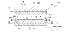
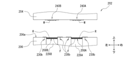
プレスユニット100Bは、先ず、開閉される一対の金型(例えば、合金工具鋼からなる複数の金型ブロック、金型プレート、金型ピラー等やその他の部材が組み付けられたもの)を有するモールド金型202を備えている。本実施形態においては、一対の金型のうち、鉛直方向において上方側の一方の金型を上型204とし、下方側の他方の金型を下型206としている。このモールド金型202は、上型204と下型206とが相互に接近・離反することで型閉じ・型開きがなされる。すなわち、鉛直方向が型開閉方向となる。 The press unit 100B is a mold having a pair of dies to be opened and closed (for example, a plurality of dies made of alloy tool steel, a die plate, a die pillar, and other members are assembled). It is equipped with a mold 202. In the present embodiment, of the pair of molds, one mold on the upper side in the vertical direction is the upper mold 204, and the other mold on the lower side is the lower mold 206. The mold mold 202 is closed and opened by the upper mold 204 and the lower mold 206 approaching and separating from each other. That is, the vertical direction is the mold opening / closing direction.

なお、モールド金型202は、公知の型開閉機構(不図示)によって型開閉が行われる。例えば、型開閉機構は、一対のプラテンと、一対のプラテンが架設される複数の連結機構(タイバーや柱部)と、プラテンを可動(昇降)させる駆動源(例えば、電動モータ)及び駆動伝達機構(例えば、トグルリンク)等を備えて構成されている(駆動用機構についてはいずれも不図示)。 The mold mold 202 is opened and closed by a known mold opening / closing mechanism (not shown). For example, the mold opening / closing mechanism includes a pair of platens, a plurality of connecting mechanisms (tie bars and pillars) on which the pair of platens are erected, a drive source (for example, an electric motor) and a drive transmission mechanism for moving (elevating) the platens. (For example, a toggle link) and the like are provided (the drive mechanism is not shown).

ここで、モールド金型202は、当該型開閉機構の一対のプラテンの間に配設されている。本実施形態においては、固定型となる上型204が固定プラテン(連結機構に固定されるプラテン)に組み付けられ、可動型となる下型206が可動プラテン(連結機構に沿って昇降するプラテン)に組み付けられている。ただし、この構成に限定されるものではなく、上型204を可動型、下型206を固定型としてもよく、あるいは、上型204、下型206共に可動型としてもよい。 Here, the mold mold 202 is arranged between a pair of platens of the mold opening / closing mechanism. In the present embodiment, the upper mold 204, which is a fixed type, is assembled to a fixed platen (a platen fixed to a connecting mechanism), and the lower mold 206, which is a movable type, is attached to a movable platen (a platen that moves up and down along the connecting mechanism). It is assembled. However, the present invention is not limited to this configuration, and the upper die 204 may be a movable type and the lower die 206 may be a fixed type, or both the upper die 204 and the lower die 206 may be a movable type.

次に、モールド金型202の下型206について具体的に説明する。下型206は、下プレート224、キャビティ駒226、クランパ228等を備え、これらが組み付けられて構成されている(図10参照)。 Next, the lower mold 206 of the mold mold 202 will be specifically described. The lower mold 206 includes a lower plate 224, a cavity piece 226, a clamper 228, and the like, and is configured by assembling these (see FIG. 10).

ここで、キャビティ駒226は、下プレート224の上面(上型204側の表面)に対して固定して組み付けられる。クランパ228は、キャビティ駒226を囲うように環状に構成され、キャビティ駒226と隣接して下プレート224の上面に対して離間(フローティング)して組み付けられる。 Here, the cavity piece 226 is fixedly assembled to the upper surface (the surface on the upper mold 204 side) of the lower plate 224. The clamper 228 is configured in an annular shape so as to surround the cavity piece 226, and is assembled adjacent to the cavity piece 226 and separated (floating) from the upper surface of the lower plate 224.

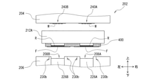
本実施形態においては、下型206が金型面(パーティング面)206aから凹むキャビティ208を有するが、キャビティ駒226がキャビティ208の奥部(底部)を構成し、クランパ228がキャビティ208の側部を構成する。換言すれば、このキャビティ駒226の上面とクランパ228の内周壁面とによって所定形状に凹んだキャビティ凹部209が形成される。 In the present embodiment, the lower mold 206 has a cavity 208 recessed from the mold surface (parting surface) 206a, but the cavity piece 226 constitutes the inner part (bottom) of the cavity 208, and the clamper 228 is on the side of the cavity 208. Make up the part. In other words, the upper surface of the cavity piece 226 and the inner peripheral wall surface of the clamper 228 form a cavity recess 209 recessed in a predetermined shape.

なお、本実施形態においては、図21等に示すように、キャビティ208が左右方向に二つ並設される構成を備えており(図中、符号208A、208B)、また、それぞれに対応するキャビティ駒226A、226Bを備えている。これにより、二つのフィルムF(モールド樹脂Rが搭載された部分)を同時に、それぞれキャビティ208A、208B内に収容することが可能となる。したがって、ワークWを二つずつ同時に樹脂モールドする構成が実現できるため、工程時間の短縮が可能となる。なお、下型206においてクランパ228をキャビティ208A、208B毎に切り分けた構成として別個に昇降できるようにし、上型204において二つのワークWの板厚差を弾性体で吸収する板厚調整機構を備えた構成としてもよい。これによれば、同時に圧縮成形する二つのワークWの厚みの差があっても傾きを生じさせずに、樹脂量の供給ばらつき等の影響を低減させながら成形できる。なお、本実施形態においては、キャビティ208A、208Bが左右方向に横並びになるように金型の部材を配置している。このため、キャビティ208A、208Bを構成するキャビティ駒226A、226Bとクランパ228とを左右で別個のチェイス構造として、これらを収容するベースに対して装置の前後方向に個々に抜き差ししてメンテナンスを行なうことができる。 In this embodiment, as shown in FIG. 21 and the like, two cavities 208 are arranged side by side in the left-right direction (reference numerals 208A and 208B in the figure), and cavities corresponding to each are provided. It is equipped with pieces 226A and 226B. This makes it possible to simultaneously accommodate the two films F (the portion on which the mold resin R is mounted) in the cavities 208A and 208B, respectively. Therefore, it is possible to realize a configuration in which two work Ws are simultaneously resin-molded, so that the process time can be shortened. In the lower mold 206, the clamper 228 can be raised and lowered separately for each of the cavities 208A and 208B, and the upper mold 204 is provided with a plate thickness adjusting mechanism that absorbs the plate thickness difference between the two workpieces W with an elastic body. It may be configured as a new type. According to this, even if there is a difference in the thickness of the two workpieces W to be compression-molded at the same time, the molding can be performed while reducing the influence of the supply variation of the resin amount without causing the inclination. In this embodiment, the mold members are arranged so that the cavities 208A and 208B are arranged side by side in the left-right direction. Therefore, the cavity pieces 226A and 226B constituting the cavities 208A and 208B and the clamper 228 are separately left and right as a chase structure, and maintenance is performed by individually inserting and removing them from the base accommodating them in the front-rear direction of the device. Can be done.

ここで、クランパ228に対向する上型204の金型面には吸引溝(不図示)が設けられ、これが吸引装置(不図示)に連通している。また、これらを囲うシール構造が設けられることで、吸引装置を駆動させて減圧することにより、型閉じされた状態でキャビティ208内の脱気を行うことが可能となる。 Here, a suction groove (not shown) is provided on the mold surface of the upper mold 204 facing the clamper 228, and this communicates with the suction device (not shown). Further, by providing a seal structure surrounding them, it is possible to degas the inside of the cavity 208 in a closed state by driving the suction device to reduce the pressure.

また、モールド金型202は、フィルムFを下型206の金型面206a側から吸引するフィルム吸引機構を備える。このフィルム吸引機構は、一例として、クランパ228を貫通して配設された吸引路230a、230bを介して吸引装置(不図示)に連通している。具体的には、吸引路230a、230bの一端が下型206の金型面206aに通じ、他端が下型206外に配設される吸引装置と接続される。これにより、吸引装置を駆動させて吸引路230a、230bからフィルムFを吸引し、キャビティ208の内面を含む金型面206aにフィルムFを吸着させて保持することが可能となる。より具体的には、吸引路230bからフィルムFを吸引し、キャビティ208の外側の金型面206aにフィルムFを吸着させて保持することが可能となり、吸引路230aからフィルムFを吸引することで、キャビティ208の内面(キャビティ凹部209の金型面)に金型面206aにフィルムFを吸着させて保持することが可能となる。 Further, the mold mold 202 includes a film suction mechanism that sucks the film F from the mold surface 206a side of the lower mold 206. As an example, this film suction mechanism communicates with a suction device (not shown) via suction paths 230a and 230b arranged so as to penetrate the clamper 228. Specifically, one end of the suction paths 230a and 230b is connected to the mold surface 206a of the lower mold 206, and the other end is connected to a suction device arranged outside the lower mold 206. As a result, the suction device can be driven to suck the film F from the suction paths 230a and 230b, and the film F can be sucked and held on the mold surface 206a including the inner surface of the cavity 208. More specifically, the film F can be sucked from the suction path 230b, and the film F can be sucked and held on the mold surface 206a outside the cavity 208, and the film F can be sucked from the suction path 230a. The film F can be attracted to and held on the mold surface 206a on the inner surface of the cavity 208 (the mold surface of the cavity recess 209).

このように、キャビティ208の内面、及び下型206の金型面206a(一部)を覆うフィルムFを設けることにより、成形品Wpの下面におけるモールド樹脂Rの部分を容易に剥離させることができるため、成形品Wpをモールド金型202から容易に取出すことが可能となる。 By providing the film F that covers the inner surface of the cavity 208 and the mold surface 206a (part) of the lower mold 206 in this way, the portion of the mold resin R on the lower surface of the molded product Wp can be easily peeled off. Therefore, the molded product Wp can be easily taken out from the mold mold 202.

また、モールド金型202は、下プレート224とクランパ228との間に付勢部材(例えば、コイルスプリング等のバネ)232を備えている。この付勢部材232を介して下プレート224にクランパ228が可動に組み付けられている。これにより、キャビティ駒226がクランパ228によって囲まれ、キャビティ駒226とクランパ228とが型開閉方向に相対的に往復動可能となっている。このように、下型206においては、下プレート224に対して、キャビティ駒226が固定して保持される一方、クランパ228が可動するよう付勢部材232を介して離間(フローティング)して保持される。このとき、クランパ228の内周面とキャビティ駒226の外周面との隙間が所定の寸法で確保される構成となっている。したがって、クランパ228を円滑に可動させることができる。 Further, the mold mold 202 includes an urging member (for example, a spring such as a coil spring) 232 between the lower plate 224 and the clamper 228. A clamper 228 is movably assembled to the lower plate 224 via the urging member 232. As a result, the cavity piece 226 is surrounded by the clamper 228, and the cavity piece 226 and the clamper 228 can reciprocate relatively in the mold opening / closing direction. As described above, in the lower mold 206, the cavity piece 226 is fixedly held with respect to the lower plate 224, while the clamper 228 is separated (floating) and held via the urging member 232 so as to be movable. To. At this time, the gap between the inner peripheral surface of the clamper 228 and the outer peripheral surface of the cavity piece 226 is secured with a predetermined dimension. Therefore, the clamper 228 can be smoothly moved.

ところで、上記の隙間は、前述のフィルム吸引機構の吸引路230aに含まれ、キャビティ駒226とクランパ228との境界(キャビティ208のコーナー部)でフィルムFを吸引する。このため、フィルム吸引機構は、シール部材234(例えば、Oリング)を備えている。シール部材234は、上記の隙間が吸引路230aとして空気漏れがないようキャビティ駒226とクランパ228(の下部)との間に設けられてシールを行う。 By the way, the above-mentioned gap is included in the suction path 230a of the above-mentioned film suction mechanism, and the film F is sucked at the boundary between the cavity piece 226 and the clamper 228 (the corner portion of the cavity 208). Therefore, the film suction mechanism includes a sealing member 234 (for example, an O-ring). The seal member 234 is provided between the cavity piece 226 and the clamper 228 (lower part) so that the above gap serves as a suction path 230a so that air does not leak, and seals the member 234.

また、下型206は、ヒータ(例えば、電熱線ヒータ)、補助ヒータ(例えば、電熱線ヒータ)、温度センサ、制御部、電源等(いずれも不図示)を備えており、加熱及びその制御が行われる。一例として、下型206のヒータは、下プレート224やこれらを収容する金型ベース(不図示)に内蔵され、主に下型206全体とワークWに熱を加える。これら下型206のヒータにより、下型206は所定温度(例えば、120℃〜180℃)に調整されて加熱される。 Further, the lower mold 206 includes a heater (for example, a heating wire heater), an auxiliary heater (for example, a heating wire heater), a temperature sensor, a control unit, a power supply, etc. (all not shown), and can be used for heating and control thereof. Will be done. As an example, the heater of the lower mold 206 is built in the lower plate 224 and the mold base (not shown) accommodating them, and mainly heats the entire lower mold 206 and the work W. The heater of the lower mold 206 adjusts the lower mold 206 to a predetermined temperature (for example, 120 ° C. to 180 ° C.) and heats the lower mold 206.

次に、モールド金型202の上型204について具体的に説明する。上型204は、上プレート222、キャビティプレート236等を備え、これらが組み付けられて構成されている。ここで、キャビティプレート236は、上プレート222の下面(下型206側の表面)に対して固定して組み付けられている。 Next, the upper mold 204 of the mold mold 202 will be specifically described. The upper mold 204 includes an upper plate 222, a cavity plate 236, and the like, and is configured by assembling these. Here, the cavity plate 236 is fixedly assembled to the lower surface of the upper plate 222 (the surface on the lower mold 206 side).

また、上型204は、ヒータ(例えば、電熱線ヒータ)、温度センサ、制御部、電源等(いずれも不図示)を備えており、加熱及びその制御が行われる。一例として、上型204のヒータは、上プレート222に内蔵され、主に上型204全体とモールド樹脂Rに熱を加える。この上型204のヒータにより、上型204は所定温度(例えば、120℃〜180℃)に調整されて加熱される。 Further, the upper die 204 includes a heater (for example, a heating wire heater), a temperature sensor, a control unit, a power supply, and the like (all not shown), and heating and control thereof are performed. As an example, the heater of the upper mold 204 is built in the upper plate 222 and mainly applies heat to the entire upper mold 204 and the mold resin R. The heater of the upper mold 204 adjusts the upper mold 204 to a predetermined temperature (for example, 120 ° C. to 180 ° C.) and heats the upper mold 204.

さらに、上型204は、ワークWをキャビティプレート236の下面における所定位置に保持するワーク保持機構240を備えている。このワーク保持機構240は、一例として、キャビティプレート236に配設された吸引路240aを介して吸引装置(不図示)に連通している。具体的には、吸引路240aの一端が上型204の金型面204aに通じ、他端が上型204外に配設される吸引装置と接続される。これにより、吸引装置を駆動させて吸引路240aからワークWを吸引し、金型面204a(ここでは、キャビティプレート236の下面)にワークWを吸着させて保持することが可能となる。また、吸引路240aを備える構成と並設して、ワークWの外周を挟持する保持爪を有した構成としてもよい。 Further, the upper die 204 is provided with a work holding mechanism 240 that holds the work W in a predetermined position on the lower surface of the cavity plate 236. As an example, the work holding mechanism 240 communicates with a suction device (not shown) via a suction path 240a arranged in the cavity plate 236. Specifically, one end of the suction path 240a is connected to the mold surface 204a of the upper mold 204, and the other end is connected to a suction device disposed outside the upper mold 204. As a result, the suction device can be driven to suck the work W from the suction path 240a, and the work W can be sucked and held on the mold surface 204a (here, the lower surface of the cavity plate 236). Further, it may be configured to have a holding claw for sandwiching the outer periphery of the work W in parallel with the configuration including the suction path 240a.

なお、本実施形態においては、図21等に示すように、ワーク保持機構240が左右方向に二つ並設される構成を備えている(図中、符号240A、240B)。これにより、二つのワークWを同時に、それぞれワーク保持機構240A、240Bで保持することが可能となる。したがって、ワークWを二つずつ同時に樹脂モールドする構成が実現できるため、工程時間の短縮が可能となる。なお、前述の板圧調整機構として、ワークWを保持するキャビティプレート236をキャビティ208A、208B毎に分けて別個に昇降できるようにすることで、同時に圧縮成形する二つのワークWの厚みの差があっても傾きを生じさせずに成形できるようにしてもよい。 In this embodiment, as shown in FIG. 21 and the like, two work holding mechanisms 240 are arranged side by side in the left-right direction (reference numerals 240A and 240B in the figure). This makes it possible to simultaneously hold the two works W by the work holding mechanisms 240A and 240B, respectively. Therefore, it is possible to realize a configuration in which two work Ws are simultaneously resin-molded, so that the process time can be shortened. As the above-mentioned plate pressure adjusting mechanism, the cavity plate 236 holding the work W is divided into the cavities 208A and 208B so that they can be raised and lowered separately, so that the difference in the thickness of the two work Ws to be compression-molded at the same time can be reduced. Even if there is, it may be possible to mold without causing inclination.

前述の通り、上記の樹脂モールド装置1の変形例として、一つの下型に一つのキャビティを設けると共に一つのワークWを配置して樹脂モールドを行い、一つの成形品を得る圧縮成形方式の樹脂モールド装置2(図28参照)のように構成してもよい。その場合、プレスユニット100Bに代えて、以下のプレスユニット500Bのような構成が考えられる。 As described above, as a modification of the above resin molding device 1, a compression molding type resin is obtained by providing one cavity in one lower mold and arranging one work W to perform resin molding to obtain one molded product. It may be configured as in the mold device 2 (see FIG. 28). In that case, instead of the press unit 100B, the following configuration such as the press unit 500B can be considered.

一例として、プレスユニット500Bは、下型206において、前述の二つのフィルム及びモールド樹脂を収容する二列のキャビティ208A、208Bに代えて、一つのフィルムを介してモールド樹脂を収容するキャビティ208を備える構成とすればよい。さらに、上型204において、前述の二つのワークを保持するワーク保持機構240A、240Bは、併せて一つのワークWを保持するワーク保持機構240として用いる構成とすればよい。 As an example, in the lower mold 206, the press unit 500B includes a cavity 208 for accommodating the mold resin via one film instead of the two rows of cavities 208A and 208B for accommodating the two films and the mold resin described above. It may be configured. Further, in the upper mold 204, the work holding mechanisms 240A and 240B for holding the above-mentioned two works may be configured to be used together as the work holding mechanism 240 for holding one work W.

(ディスペンスユニット)
続いて、樹脂モールド装置1が備えるディスペンスユニット100Cの構成を主に、フィルムF及びモールド樹脂Rの供給動作について詳しく説明する。
(Dispens unit)
Subsequently, the configuration of the dispense unit 100C included in the resin molding apparatus 1 will be mainly described, and the supply operation of the film F and the molding resin R will be described in detail.

前述の通り、ディスペンスユニット100Cは、フィルムF及びモールド樹脂Rの供給等を行うユニットである。本実施形態においては、フィルムF及びモールド樹脂Rをモールド金型202へ搬送する際に、これらを保持して搬送するための治具として搬送具400が用いられる。すなわち、この搬送具400を冶具として用いることで、モールド樹脂Rを保持してフィルムFと共に搬送することが行われることになる。また、搬送具400は、フィルムFをその長手方向を平行させて並べて保持可能となっている(詳細は後述)。 As described above, the dispense unit 100C is a unit that supplies the film F, the mold resin R, and the like. In the present embodiment, when the film F and the mold resin R are transported to the mold mold 202, the transport tool 400 is used as a jig for holding and transporting the film F and the mold resin R. That is, by using this transport tool 400 as a jig, the mold resin R can be held and transported together with the film F. Further, the carrier 400 can hold the films F side by side in parallel in the longitudinal direction (details will be described later).

ディスペンスユニット100Cは、先ず、フィルムF及びモールド樹脂Rを保持していない状態の搬送具400が載置され適宜のクリーニングが行われる準備テーブル302を備えている。例えば、モールド金型202から搬出された搬送具400は、モールド樹脂Rが付着し動作不良の原因となり得る。そこで、後述する貫通孔を含めて表面をブラシや吸引機構(いずれも不図示)でクリーニングすることで動作不良を防止できる。 The dispense unit 100C first includes a preparation table 302 on which the transporter 400 in a state where the film F and the mold resin R are not held is placed and appropriate cleaning is performed. For example, the transport tool 400 carried out from the mold mold 202 may have the mold resin R adhered to it and cause a malfunction. Therefore, it is possible to prevent malfunction by cleaning the surface including the through hole described later with a brush or a suction mechanism (not shown).

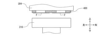
次に、搬送具400を保持して、これを複数の所定位置(テーブル)間で搬送する搬送具ピックアップ304を備えている。なお、搬送具400を保持する機構として、公知の保持機構(例えば、保持爪を有して挟持する構成、吸引装置に連通する吸引孔を有して吸着する構成、等)を有している(不図示)。例えば、搬送具400の外周部分に凹凸部を設け、搬送具ピックアップ304の下面から下に向けて立設させた保持爪に凹凸部を引っ掛けて保持し搬送する構成を採用することができる。 Next, a transport tool pickup 304 that holds the transport tool 400 and transports the transport tool 400 between a plurality of predetermined positions (tables) is provided. As a mechanism for holding the carrier 400, it has a known holding mechanism (for example, a structure having a holding claw for holding, a structure having a suction hole communicating with a suction device, and the like). (Not shown). For example, it is possible to adopt a configuration in which an uneven portion is provided on the outer peripheral portion of the transport tool 400, and the uneven portion is hooked on a holding claw that is erected downward from the lower surface of the transport tool pickup 304 to hold and transport the uneven portion.

ここで、搬送具ピックアップ304は、前後、左右及び上下方向に移動可能に構成されている。これにより、準備テーブル302上に載置された搬送具400を保持して、後述のフィルムテーブル308及び樹脂投下テーブル310へ搬送することが可能となる。 Here, the carrier pickup 304 is configured to be movable in the front-back, left-right, and up-down directions. This makes it possible to hold the transport tool 400 placed on the preparation table 302 and transport it to the film table 308 and the resin dropping table 310, which will be described later.

次に、ディスペンスユニット100Cは、準備テーブル302の後方となる位置において、長尺状のフィルムFがロール状に巻かれたフィルムロール306と、フィルムロール306の上方(本実施形態においては斜め上方)に配設されて、フィルムロール306から繰出されたフィルムFが所定長さの短冊状に切断されて保持されるフィルムテーブル(第1テーブル)308とを備えている。 Next, the dispense unit 100C has a film roll 306 in which a long film F is wound in a roll shape and an upper part of the film roll 306 (obliquely upward in the present embodiment) at a position behind the preparation table 302. The film F is provided with a film table (first table) 308 which is arranged in a film roll 306 and is cut and held in a strip shape having a predetermined length.

一例として、フィルムテーブル308、及びフィルムロール306は、上下方向において、上からその順に階層状に並設されている構成(前後左右方向のオフセットを含む)を備えている。これにより、各構成が平面的に並設される従来装置と比較して、装置の設置面積を低減することが可能となる。 As an example, the film table 308 and the film roll 306 have a configuration (including an offset in the front-back and left-right directions) in which the film table 308 and the film roll 306 are arranged in a layered manner in that order from the top in the vertical direction. This makes it possible to reduce the installation area of the device as compared with the conventional device in which each configuration is arranged in a plane.

本実施形態においては、フィルムロール306として、二つのフィルムロール306A、306Bが左右方向に並べて配設されている。これにより、フィルムテーブル308上に、同時に、二つの同形のフィルムFを供給することが可能となる。ここで、フィルムロール306A、306Bは、その中心軸307aで支持して設置してもよく、フィルムロール306A、306Bの外形よりも小さい間隔で複数設けたローラー307bで下方から支持して設置してもよい。この場合、フィルムロール306A、306Bをローラー307bで下方から支持する構成とすることで、2つ並べられたフィルムロール306A、306Bを中心軸307aの抜き差しを不要として簡易に取替えをすることができる。また、フィルムロール306のフィルムテーブル308への送り出しには、端部を挟み込んで引き出す構成やフィルムテーブル308の手前に設けた駆動式のローラーで送り出す構成としてもよい。 In the present embodiment, as the film roll 306, two film rolls 306A and 306B are arranged side by side in the left-right direction. This makes it possible to simultaneously supply two films F having the same shape on the film table 308. Here, the film rolls 306A and 306B may be supported and installed by the central shaft 307a thereof, or may be supported and installed from below by a plurality of rollers 307b provided at intervals smaller than the outer shape of the film rolls 306A and 306B. May be good. In this case, by supporting the film rolls 306A and 306B from below with the rollers 307b, the two film rolls 306A and 306B arranged side by side can be easily replaced without the need for inserting and removing the central shaft 307a. Further, the film roll 306 may be fed to the film table 308 by a configuration in which an end portion is sandwiched and pulled out, or a configuration in which a drive-type roller provided in front of the film table 308 is used to feed the film roll 306.

一方、フィルムテーブル308は、長尺状のフィルムFを切断する機構として、公知の切断機構(例えば、固定刃カッター、熱溶融カッター、等)を有している(不図示)。また、二つのフィルムFを保持する機構として、公知の保持機構(例えば、吸引装置に連通する吸引孔を有して吸着する構成、等)を有している(不図示)。このフィルムテーブル308では、ここで切断されたフィルムFと搬送具400とが組み合わされる。 On the other hand, the film table 308 has a known cutting mechanism (for example, a fixed blade cutter, a heat melting cutter, etc.) as a mechanism for cutting the long film F (not shown). Further, as a mechanism for holding the two films F, a known holding mechanism (for example, a configuration having a suction hole communicating with a suction device for suction, etc.) is provided (not shown). In the film table 308, the film F cut here and the carrier 400 are combined.

ここで、本実施形態に係る搬送具400は、図9に示すように、上面と下面とが平行となる平面に形成された概略平板状の形状を有すると共に、中央部分にフィルムFを保持する搬入フィルム保持部を二列有している(図中、400A、400B)。また、各搬入フィルム保持部400A、400Bには、各フィルムFに対応する位置(各フィルムFを保持する位置)において、各フィルムFが上面から見て露出するように貫通孔に形成された樹脂投入孔400a、400bが配設されている。この樹脂投入孔400a、400bは、前述したキャビティ凹部209の形状に対応して形成されることで、樹脂投入孔400a、400b内にモールド樹脂Rが投下され保持したときに、適宜な状態でモールド樹脂Rを準備することができることになる。 Here, as shown in FIG. 9, the conveyor 400 according to the present embodiment has a substantially flat plate-like shape formed in a plane in which the upper surface and the lower surface are parallel to each other, and holds the film F in the central portion. It has two rows of carry-in film holding portions (400A and 400B in the figure). Further, in each of the carry-in film holding portions 400A and 400B, a resin formed in a through hole so that each film F is exposed when viewed from the upper surface at a position corresponding to each film F (a position for holding each film F). Input holes 400a and 400b are arranged. The resin injection holes 400a and 400b are formed corresponding to the shape of the cavity recess 209 described above, so that when the mold resin R is dropped and held in the resin injection holes 400a and 400b, the mold resin R is molded in an appropriate state. The resin R can be prepared.

さらに、樹脂投入孔400a、400bの周囲には、吸引力を発生させてフィルムを保持する複数の第1吸引孔400cが配設されている。なお、第1吸引孔400cは、後述の第3保持部212Aに設けられる第2吸引孔212bや、後述の搬送具ピックアップ304に設けられる第3吸引孔(不図示)を介して(連通して)、吸引装置(不図示)にて発生する吸引力が伝達される構成となっている。上記の構成によれば、搬送具ピックアップ304によりフィルムテーブル308上に搬送された搬送具400の下面に二つのフィルムFを左右方向に並べて吸引させた状態で保持させることが可能となる。なお、フィルムFの外周を保持爪で挟み込んで保持する構成としてもよい。 Further, a plurality of first suction holes 400c for generating a suction force to hold the film are arranged around the resin injection holes 400a and 400b. The first suction hole 400c communicates with the second suction hole 212b provided in the third holding portion 212A described later and the third suction hole (not shown) provided in the transport tool pickup 304 described later. ), The suction force generated by the suction device (not shown) is transmitted. According to the above configuration, it is possible to hold the two films F in a state of being sucked side by side in the left-right direction on the lower surface of the transport tool 400 transported on the film table 308 by the transport tool pickup 304. The outer periphery of the film F may be sandwiched between the holding claws to hold the film F.

次に、フィルムテーブル308に対して側方(一例として、右方)に配設されると共に前後左右方向に移動可能に構成されて、搬送具ピックアップ304により搬送された搬送具400(下面に二つのフィルムFが保持された状態)が載置される樹脂投下テーブル(第2テーブル)310を備えている。なお樹脂投下テーブル310は、載置された搬送具400を保持する機構として、公知の保持機構(例えば、保持爪を有して挟持する構成、吸引装置に連通する吸引孔を有して吸着する構成、等)を有している(不図示)。 Next, the transport tool 400 (two on the lower surface) which is arranged laterally (for example, to the right) with respect to the film table 308 and is configured to be movable in the front-back and left-right directions and is conveyed by the transport tool pickup 304. A resin dropping table (second table) 310 on which the film F is held) is provided. The resin dropping table 310 has a known holding mechanism (for example, a configuration having holding claws for holding the carrier 400, and a suction hole communicating with the suction device) as a mechanism for holding the mounted transport tool 400. Has a configuration, etc. (not shown).

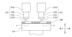
さらに、フィルムテーブル308に対して上記の樹脂投下テーブル310を間に挟む配置で側方(一例として、右方)で、樹脂投下テーブル310よりも高い位置にディスペンサ312を備えている。このディスペンサ312は、樹脂投下テーブル310に載置された搬送具400における樹脂投入孔400a、400bにモールド樹脂Rを投入して、露出するフィルムF上(樹脂投入孔400a、400bの内側)に当該モールド樹脂Rを搭載(投下)する。このディスペンサ312は、例えば、モールド樹脂Rを貯留するホッパ312aと、投下される樹脂の重量を計量する重量計312bと、計量されたモールド樹脂Rが振動フィーダ(不図示)で送り出されるトラフ312cと、トラフ312cから送り出され投下されるモールド樹脂Rの投下位置を規制するノズル312dとを備えて構成される。 Further, the dispenser 312 is provided on the side (for example, on the right side) of the film table 308 so as to sandwich the resin dropping table 310 in between, and at a position higher than the resin dropping table 310. The dispenser 312 puts the mold resin R into the resin charging holes 400a and 400b of the transporter 400 placed on the resin dropping table 310, and puts the mold resin R on the exposed film F (inside the resin charging holes 400a and 400b). The mold resin R is mounted (dropped). The dispenser 312 includes, for example, a hopper 312a for storing the mold resin R, a weighing scale 312b for measuring the weight of the dropped resin, and a trough 312c for which the measured mold resin R is sent out by a vibration feeder (not shown). , A nozzle 312d that regulates the dropping position of the mold resin R sent out from the trough 312c and dropped.

ここで、本実施形態に係る樹脂投下テーブル310は、前後及び左右方向に移動可能に構成されている(図1中、三箇所の位置で図示している)。左右方向の移動により、フィルムFが保持された状態で樹脂投下テーブル310上に載置された搬送具400をディスペンサ312の下方へ進退移動することが可能となる。これにより、ディスペンサ312とフィルムテーブル308との中間の位置とディスペンサ312のノズル312dの直下となる位置との間で搬送具400を移動することが可能となる。また、前後方向の移動により、モールド樹脂Rを搭載したフィルムFが保持された状態の搬送具400を所定位置(後述の第3保持部212Aによって搬送具400の保持が行われる位置)へ搬送することが可能となる。なお、変形例として、樹脂投下テーブル310が左右移動する構成に代えて、ディスペンサ312によって当該移動範囲の移動を置き換える構成とすることも考えられる。また、樹脂投下テーブル310が前後移動する構成に代えて、第3保持部212A(後述)によって当該移動範囲の移動を置き換える構成とすることも考えられる(いずれも不図示)。 Here, the resin dropping table 310 according to the present embodiment is configured to be movable in the front-rear direction and the left-right direction (shown at three positions in FIG. 1). By moving in the left-right direction, the carrier 400 placed on the resin dropping table 310 can be moved back and forth below the dispenser 312 while the film F is held. This makes it possible to move the carrier 400 between the intermediate position between the dispenser 312 and the film table 308 and the position directly below the nozzle 312d of the dispenser 312. Further, by moving in the front-rear direction, the transport tool 400 in a state where the film F on which the mold resin R is held is held is transported to a predetermined position (a position where the transport tool 400 is held by the third holding portion 212A described later). Is possible. As a modification, instead of the configuration in which the resin dropping table 310 moves left and right, a configuration in which the movement of the moving range is replaced by the dispenser 312 may be considered. Further, instead of the configuration in which the resin dropping table 310 moves back and forth, it is conceivable to have a configuration in which the movement of the moving range is replaced by the third holding portion 212A (described later) (neither is shown).

また、樹脂投下テーブル310を前後及び左右方向の所定経路で移動させながら、二つのノズル312dからモールド樹脂Rを樹脂投入孔400a、400bに送出することによって、樹脂投入孔400a、400b内に露出するフィルムF上にモールド樹脂Rを所定厚さで偏りなく敷き詰めることが可能となる。これにより、フィルムF上のモールド樹脂Rの偏りに起因する不良品発生の防止が可能となる。 Further, the mold resin R is sent out from the two nozzles 312d to the resin charging holes 400a and 400b while moving the resin dropping table 310 in predetermined paths in the front-back and left-right directions, so that the mold resin R is exposed in the resin charging holes 400a and 400b. The mold resin R can be spread evenly on the film F with a predetermined thickness. This makes it possible to prevent the generation of defective products due to the bias of the mold resin R on the film F.

ここで、本実施形態に係るディスペンサ312は、搬送具400における二列の樹脂投入孔400a、400bにそれぞれモールド樹脂を投入する二つのノズル312dを有している。一例として、右側の樹脂投入孔400aに対応する位置に一方のノズル312dが配設されると共に、左側の樹脂投入孔400bに対応する位置に他方のノズル312dが配設されている。換言すれば、二つのノズル312dのそれぞれの中心間距離と、樹脂投入孔400a、400bのそれぞれの中心間距離とが同一になるように構成される。これにより、同時にそれぞれの樹脂投入孔400a、400bの同一対応位置を通過させながらモールド樹脂Rを投入することが可能となり、移動距離及び移動時間が最短となる一経路で、二つのフィルムF上にモールド樹脂Rを敷き詰めることが可能となる。したがって、工程時間の大幅な短縮が可能となる。なお、変形例として、一つのノズルを有して、所定の一経路で二つのフィルムF上に順番にモールド樹脂Rを敷き詰める構成としてもよい(不図示)。 Here, the dispenser 312 according to the present embodiment has two nozzles 312d for charging the mold resin into the two rows of resin charging holes 400a and 400b in the transport tool 400, respectively. As an example, one nozzle 312d is arranged at a position corresponding to the resin charging hole 400a on the right side, and the other nozzle 312d is arranged at a position corresponding to the resin charging hole 400b on the left side. In other words, the distance between the centers of the two nozzles 312d and the distance between the centers of the resin input holes 400a and 400b are configured to be the same. As a result, the mold resin R can be charged while passing through the same corresponding positions of the respective resin charging holes 400a and 400b at the same time, and the moving distance and the moving time can be minimized on two films F in one path. It is possible to spread the mold resin R. Therefore, the process time can be significantly reduced. As a modification, a configuration in which one nozzle is provided and the mold resin R is sequentially spread on two films F in a predetermined path may be used (not shown).

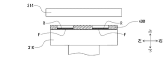
次に、モールド樹脂Rが搭載されたフィルムFが保持された状態の搬送具400の上面側から加熱することによって、当該モールド樹脂Rを加熱する樹脂ヒータ314を備えている。なお、搬送具400(モールド樹脂R)を加熱する構成として、樹脂ヒータ314の下面に、公知の加熱機構(例えば、電熱線ヒータ、赤外線ヒータ、等)が配設されている(不図示)。これにより、搬送具400によって二つのフィルムF上に搭載された状態で保持されたモールド樹脂Rを、同時に加熱することが可能となる。 Next, a resin heater 314 for heating the mold resin R by heating from the upper surface side of the transporter 400 in a state where the film F on which the mold resin R is mounted is held is provided. As a configuration for heating the carrier 400 (mold resin R), a known heating mechanism (for example, a heating wire heater, an infrared heater, etc.) is provided on the lower surface of the resin heater 314 (not shown). This makes it possible to simultaneously heat the mold resin R held on the two films F by the transport tool 400.

ここで、本実施形態に係る樹脂ヒータ314は、樹脂投下テーブル310の移動経路上、より具体的には、ディスペンサ312のノズル312dの直下となる位置から、後述の第3保持部212Aによって搬送具400の保持が行われる位置まで移動する間の経路途中に配設されている。これにより、ディスペンサ312のノズル312dによって搬送具400に保持されたフィルムF上にモールド樹脂Rが投入された直後に、当該モールド樹脂Rを加熱する工程を行うことが可能となる。したがって、特に、モールド樹脂Rとして、顆粒状、粉末状等の樹脂を用いた場合に、フィルムF上への搭載直後に加熱して表面に位置する粉末状等の樹脂を加熱溶融し一体化させることができる。これにより、塵埃(樹脂の微細粉末等)の発生を防止して、塵埃が装置内で拡散することによる動作不良や製品不良の発生を防止することが可能となる。 Here, the resin heater 314 according to the present embodiment is transported by a third holding portion 212A, which will be described later, from a position on the moving path of the resin dropping table 310, more specifically, directly under the nozzle 312d of the dispenser 312. It is arranged in the middle of the path while moving to the position where the holding of 400 is performed. This makes it possible to perform a step of heating the mold resin R immediately after the mold resin R is charged onto the film F held by the conveyor 400 by the nozzle 312d of the dispenser 312. Therefore, in particular, when a resin such as granules or powder is used as the mold resin R, the resin such as powder located on the surface is heated and melted and integrated by heating immediately after mounting on the film F. be able to. This makes it possible to prevent the generation of dust (fine powder of resin, etc.) and prevent the generation of malfunctions and product defects due to the diffusion of dust in the apparatus.

なお、樹脂ヒータ314の前後の位置において、樹脂投入孔400a、400b内においてフィルムF上に投下し供給したモールド樹脂Rの外観を計測する供給樹脂計測器315を備えてもよい。この供給樹脂検査器315は、カメラ(単眼カメラや複眼カメラ)を樹脂投下テーブル310の移動経路の上方に備えることで、これらの出力値や撮像画像を用いて、投下されたモールド樹脂Rの厚みや形状を記録するのに利用することができる。これにより、例えば、成形品Wpの成形厚みとの実際の情報とを紐付けてデータを保存することで、これらを作業者が比較し、モールド樹脂Rの投下条件を選定できるようにすることもできる。これにより、モールド樹脂Rの供給に関するトレーサビリティを確保して、成形品質を維持することができる。 A supply resin measuring instrument 315 may be provided at positions before and after the resin heater 314 to measure the appearance of the mold resin R dropped and supplied onto the film F in the resin input holes 400a and 400b. The supply resin inspection device 315 is provided with a camera (monocular camera or compound eye camera) above the moving path of the resin dropping table 310, and the thickness of the dropped mold resin R is used by using these output values and captured images. It can be used to record the shape and shape. Thereby, for example, by associating the actual information with the molding thickness of the molded product Wp and saving the data, the operator can compare these and select the drop condition of the mold resin R. can. As a result, traceability regarding the supply of the mold resin R can be ensured, and the molding quality can be maintained.

次に、ディスペンスユニット100Cの各機構と協働する第2ローダ212は第3保持部212Aを備えている。この第3保持部212Aは、その下面において、樹脂投下テーブル310上に載置された搬送具400を受け取り、下型206の所定保持位置へ搬送すると共に、フィルムF及びモールド樹脂Rの保持が解放された搬送具400を前述の準備テーブル302上へ搬送する。なお、第3保持部212Aは、当該搬送具400を保持する搬送具保持部212aとして、公知の保持機構(例えば、保持爪を有して挟持する構成、吸引装置に連通する吸引孔を有して吸着する構成、等)を有している。さらに、所定位置で保持する搬送具400の第1吸引孔400cに連通する位置に配設されて、吸引装置(不図示)による吸引力を発生(伝達)させる第2吸引孔212bを有している。これにより、搬送具400の下面に二つのフィルムF(それぞれモールド樹脂Rが搭載された状態)を左右方向に並べて吸着させた状態を維持しながら、下型206の所定保持位置(キャビティ208が配設された位置)へ搬送することが可能となる。なお、搬送具400の下面で二つのフィルムFの外周を挟持して保持する保持爪を有する第3保持部212Aとしてもよい。 Next, the second loader 212 that cooperates with each mechanism of the dispense unit 100C includes a third holding portion 212A. The third holding portion 212A receives the carrier 400 placed on the resin dropping table 310 on its lower surface, conveys it to a predetermined holding position of the lower mold 206, and releases the holding of the film F and the mold resin R. The transported tool 400 is transported onto the above-mentioned preparation table 302. The third holding portion 212A has a known holding mechanism (for example, a configuration having a holding claw to hold the transport tool 400, and a suction hole communicating with the suction device) as the transport tool holding portion 212a for holding the transport tool 400. It has a structure that adsorbs, etc.). Further, it has a second suction hole 212b that is arranged at a position communicating with the first suction hole 400c of the transport tool 400 to be held at a predetermined position and generates (transmits) suction force by a suction device (not shown). There is. As a result, while maintaining the state in which the two films F (each in which the mold resin R is mounted) are arranged side by side in the left-right direction and adsorbed on the lower surface of the transport tool 400, the predetermined holding position (cavity 208 is arranged) of the lower mold 206 is arranged. It is possible to transport to the installed position). The third holding portion 212A may have a holding claw that sandwiches and holds the outer circumferences of the two films F on the lower surface of the carrier 400.

ここで、本実施形態に係る第3保持部212Aを備えた第2ローダ212は、前後、左右及び上下方向に移動可能に構成されている。左右方向の移動により、搬送具400(モールド樹脂Rがそれぞれ搭載された二つのフィルムFが保持された状態)をディスペンスユニット100Cからプレスユニット100Bへ搬送する動作が可能となる。また、前後方向の移動により、搬送具400(モールド樹脂Rがそれぞれ搭載された二つのフィルムFが保持された状態)をモールド金型202の外部から内部へ(すなわち、型開きした状態の上型204と下型206との間へ)搬送する動作が可能となる。 Here, the second loader 212 provided with the third holding portion 212A according to the present embodiment is configured to be movable in the front-back, left-right, and up-down directions. The movement in the left-right direction enables an operation of transporting the transport tool 400 (a state in which two films F on which the mold resin R is mounted) is transported from the dispense unit 100C to the press unit 100B. Further, by moving in the front-rear direction, the conveyor 400 (a state in which the two films F on which the mold resin R is mounted is held) is moved from the outside to the inside of the mold mold 202 (that is, the upper mold in a state where the mold is opened). The operation of transporting (between 204 and the lower die 206) becomes possible.

さらに、上下方向の移動(前後、もしくは左右方向の移動を組合わせる場合もある)により、樹脂投下テーブル310上に載置された搬送具400(モールド樹脂Rがそれぞれ搭載された二つのフィルムFが保持された状態)を保持する動作が可能となる。この場合、下型206の所定保持位置(キャビティ208が配設された位置)で搬送具400を保持しながらモールド樹脂Rがそれぞれ搭載された二つのフィルムFの保持を解放して、二つのキャビティ208A、208B(金型面206aを一部含む)にそれぞれ(一対一で)載置する動作も可能となる。さらに、フィルムF及びモールド樹脂Rの保持が解放された状態の搬送具400を前述の準備テーブル302上へ載置する動作も可能となる。なお、変形例として、第3保持部212Aの移動範囲の一部を、他の機構(樹脂投下テーブル310、下型206、等)の移動によって置き換える構成とすることも考えられる(不図示)。 Further, by moving in the vertical direction (in some cases, the movement in the front-back direction or the movement in the left-right direction may be combined), the conveyor 400 (two films F on which the mold resin R is mounted) placed on the resin dropping table 310 is formed. The operation of holding the held state) becomes possible. In this case, while holding the carrier 400 at the predetermined holding position (position where the cavity 208 is arranged) of the lower mold 206, the holding of the two films F on which the mold resin R is mounted is released, and the holding of the two cavities is released. It is also possible to place (one-to-one) on each of 208A and 208B (including a part of the mold surface 206a). Further, it is also possible to place the carrier 400 in a state where the holding of the film F and the mold resin R is released on the above-mentioned preparation table 302. As a modification, it is conceivable that a part of the moving range of the third holding portion 212A is replaced by moving another mechanism (resin dropping table 310, lower mold 206, etc.) (not shown).

次に、第2ローダ212は、その樹脂モールドされた成形品Wpがモールド金型202(ここでは、上型204)から取出された後に下型206に残留するフィルム(使用済みフィルム)Fdを保持して、所定位置(後述のフィルムディスポーザ316)へ搬送する第4保持部212Bを備えている。なお第4保持部212Bは、使用済みフィルムFdを保持する搬出フィルム保持部として、公知の保持機構(例えば、吸引装置に連通する吸引孔を有して吸着する構成、等)を有している(図中、符号212c、212d)。 Next, the second loader 212 holds the film (used film) Fd that remains in the lower mold 206 after the resin-molded molded product Wp is taken out from the mold mold 202 (here, the upper mold 204). A fourth holding portion 212B is provided for transporting the film to a predetermined position (film disposer 316 described later). The fourth holding portion 212B has a known holding mechanism (for example, a configuration having a suction hole communicating with a suction device for suction, etc.) as a carry-out film holding portion for holding the used film Fd. (In the figure, reference numerals 212c, 212d).

また、本実施形態に係る第4保持部212Bは、上記の搬出フィルム保持部212c、212dが、モールド金型202(下型206)の二つのキャビティ208A、208Bに対応する位置に、左右方向に二列並設された構成となっている。つまり、フィルムFをその長手方向を平行させて並べて保持可能となっている。これにより、樹脂モールド後にモールド金型202(下型206)によって左右方向に並べて保持された二つの使用済みフィルムFdを、同時に、左右方向に並べて保持し、搬送することが可能となる。 Further, in the fourth holding portion 212B according to the present embodiment, the carry-out film holding portions 212c and 212d are located at positions corresponding to the two cavities 208A and 208B of the mold mold 202 (lower mold 206) in the left-right direction. It has a structure in which two rows are arranged side by side. That is, the films F can be held side by side with their longitudinal directions parallel to each other. This makes it possible to simultaneously hold and convey two used films Fd arranged side by side in the left-right direction by the mold mold 202 (lower mold 206) after resin molding.

ここで、本実施形態においては、第4保持部212Bと、上記の第3保持部212Aとが、第2ローダ212として一体に構成されている。一例として、第2ローダ212は、前方側に搬送具保持部212aを有する第3保持部212Aが配設され、後方側に左右二列の搬出フィルム保持部212c、212dを有する第4保持部212Bが配設されている。したがって、第3保持部212A及び第4保持部212Bは、第2ローダ212として一体で前後、左右及び上下方向に移動可能な構成となっている。これにより、装置構成の簡素化及び小型化が可能となるばかりでなく、モールド樹脂Rが搭載されたフィルムF、使用済みフィルムFd共に、二つずつ同時に搬送する構成が実現できるため、工程時間の短縮も可能となる。 Here, in the present embodiment, the fourth holding portion 212B and the above-mentioned third holding portion 212A are integrally configured as the second loader 212. As an example, the second loader 212 has a third holding portion 212A having a transporter holding portion 212a on the front side, and a fourth holding portion 212B having two rows of left and right carry-out film holding portions 212c and 212d on the rear side. Are arranged. Therefore, the third holding portion 212A and the fourth holding portion 212B are configured to be integrally movable as the second loader 212 in the front-back, left-right, and up-down directions. This not only makes it possible to simplify and reduce the size of the device configuration, but also realizes a configuration in which two films F and two used films Fd on which the mold resin R is mounted are simultaneously conveyed, so that the process time can be reduced. It can also be shortened.

なお、変形例として、第4保持部212Bを備えたローダを、上記の第3保持部212Aを備えたローダとは別体に構成することも考えられる(不図示)。その場合には、上記の第3保持部212Aと同様に移動可能な構成とすればよい。 As a modification, it is conceivable that the loader provided with the fourth holding portion 212B is configured separately from the loader provided with the third holding portion 212A (not shown). In that case, the configuration may be movable in the same manner as the above-mentioned third holding portion 212A.

次に、ディスペンスユニット100Cは、第4保持部212Bにより搬送された使用済みフィルムFdが収納されるフィルムディスポーザ316を備えている。一例として、フィルムディスポーザ316は、上部(上面部分)が開口する箱状に形成されている。これにより、使用済みフィルムFdを搬送する第4保持部212Bがフィルムディスポーザ316の直上位置に到達したときに、第4保持部212Bの搬送動作を停止すると共に、使用済みフィルムFdの保持を解放することによって、当該使用済みフィルムFdを落下させてフィルムディスポーザ316内へ収納することが可能となる。 Next, the dispense unit 100C includes a film disposer 316 in which the used film Fd conveyed by the fourth holding portion 212B is stored. As an example, the film disposer 316 is formed in a box shape with an upper portion (upper surface portion) open. As a result, when the fourth holding portion 212B that conveys the used film Fd reaches the position directly above the film disposer 316, the conveying operation of the fourth holding portion 212B is stopped and the holding of the used film Fd is released. This makes it possible to drop the used film Fd and store it in the film disposer 316.

以上、説明した通り、本実施形態に係る構成によれば、短冊状のワークWが二つ供給され、加工(樹脂モールド)後に成形品Wpが二つ取出される動作を効率的に行うことができる装置の実現を図ることができる。特に、一つの下型に二つのキャビティ208A、208Bを設けると共に二つのワークWを配置して一括して樹脂モールドする際に、二つのフィルムFにそれぞれモールド樹脂Rが搭載された状態を維持しながら、下型206のキャビティ208A、208Bへ搬送することが可能となる。したがって、従来装置と比較して、工程や装置構造の複雑化を抑制しつつ、生産性を大幅に向上させることが可能となる。さらに、一つの下型206に二つのキャビティ208A、208Bを設けると共に二つのワークWを配置して一つ(一枚)のフィルムFで全てを覆う構成と比較して、フィルム使用量の低減を図ることも可能となる。 As described above, according to the configuration according to the present embodiment, it is possible to efficiently perform the operation of supplying two strip-shaped workpieces W and taking out two molded products Wp after processing (resin molding). It is possible to realize a device that can be used. In particular, when two cavities 208A and 208B are provided in one lower mold and two work Ws are arranged and resin-molded together, the state in which the mold resin R is mounted on each of the two films F is maintained. However, it can be conveyed to the cavities 208A and 208B of the lower mold 206. Therefore, as compared with the conventional device, it is possible to significantly improve the productivity while suppressing the complexity of the process and the device structure. Further, the amount of film used can be reduced as compared with the configuration in which two cavities 208A and 208B are provided in one lower mold 206 and two work Ws are arranged and covered with one (one sheet) film F. It is also possible to plan.

また、フィルムFの供給に用いられるフィルムテーブル308と、モールド樹脂Rの供給に用いられる樹脂投下テーブル310とを、別々の構成として設けて、並行的に処理を行うことが可能となるため、従来装置よりも工程時間を短縮することが可能となる。 Further, since the film table 308 used for supplying the film F and the resin dropping table 310 used for supplying the mold resin R are provided as separate configurations, the processing can be performed in parallel. It is possible to shorten the process time as compared with the device.

前述の通り、上記の樹脂モールド装置1の変形例として、一つの下型に一つのキャビティを設けると共に一つのワークWを配置して樹脂モールドを行い、一つの成形品を得る圧縮成形方式の樹脂モールド装置2(図28参照)のように構成してもよい。この場合、フィルムFとしては、上述した短冊フィルムとしてのフィルムFよりも幅の広い幅広フィルムを用いる構成とすることができる。この幅広フィルムとしては、短冊フィルムよりも幅の広い正方形や長方形の枚葉形式のフィルムFを用いるのが簡易である。ただし、幅広フィルムとしては、短冊フィルムよりも幅が広ければ丸形に切り抜いた枚葉形式のフィルムFを用いてもよい。その場合、ディスペンスユニット100Cに代えて、以下のディスペンスユニット500Cのような構成が考えられる。 As described above, as a modification of the above resin molding device 1, a compression molding type resin is obtained by providing one cavity in one lower mold and arranging one work W to perform resin molding to obtain one molded product. It may be configured as in the mold device 2 (see FIG. 28). In this case, as the film F, a wide film having a width wider than that of the film F as the strip film described above can be used. As this wide film, it is easy to use a square or rectangular sheet-fed film F having a width wider than that of a strip film. However, as the wide film, a sheet-fed film F cut out in a round shape may be used as long as it is wider than the strip film. In that case, instead of the dispense unit 100C, the following configuration such as the dispense unit 500C can be considered.

一例として、ディスペンスユニット500Cは、前述の搬送具400の二列の搬入フィルム保持部400A、400Bと、一つのフィルムF(幅広フィルム)を保持する大型搬入フィルム保持部516とを置き換えて設置可能な構成とすればよい。さらに、前述の二列の搬出フィルム保持部212c、212dは、二つの短冊フィルムである使用済みフィルムFdでも、一つの幅広フィルムである使用済みフィルムFdでも吸着して保持できるような構成とすればよい。 As an example, the dispense unit 500C can be installed by replacing the two rows of carry-in film holding portions 400A and 400B of the above-mentioned carrier 400 with the large carry-in film holding portion 516 that holds one film F (wide film). It may be configured. Further, if the above-mentioned two rows of carry-out film holding portions 212c and 212d are configured to be able to adsorb and hold both the used film Fd, which is two strip films, and the used film Fd, which is one wide film. good.

このように、短冊フィルムと幅広フィルムとを切り替えて使用可能な構成については、例えば、第3保持部212Aが、短冊用と幅広用の2種類の搬送具400を共通して保持する搬送具保持部212aを有する構成とすることが考えられる。搬送具保持部212aで保持される第一の搬送具400としては、短冊フィルムである二つのフィルムFをその長手方向を平行にさせて並べて保持可能なように、二列の搬入フィルム保持部400A、400Bを有する一つの短冊フィルム搬送具400である。搬送具保持部212aで保持される第二の搬送具400としては、一つの幅広フィルムであるフィルムFを保持する一つの搬入フィルム保持部516を有する搬送具400を共通して保持する搬送具保持部212aを有する構成とすることが考えられる。 As for the configuration in which the strip film and the wide film can be switched and used in this way, for example, the third holding portion 212A holds the transport tool 400 for commonly holding the two types of transport tools 400 for the strip film and the wide film. It is conceivable that the configuration has a portion 212a. As the first carrier 400 held by the carrier holding section 212a, two rows of carry-in film holding sections 400A are used so that two films F, which are strip films, can be held side by side with their longitudinal directions parallel to each other. , 400B, one strip film carrier 400. As the second carrier 400 held by the carrier holding section 212a, the carrier holding that commonly holds the carrier 400 having one carry-in film holding section 516 that holds the film F which is one wide film. It is conceivable that the configuration has a portion 212a.

このような構成とすることで、成形品Wpに加工するワークWが短冊ワーク、又は、幅広ワークのいずれのワークWであるかに応じて、異なる搬送具400を共通の搬送具保持部212aにより保持してモールド樹脂Rと共にフィルムFを搬入することができるため、簡易な切り替えでフィルムFの供給ができる構成とすることができる。 With such a configuration, different transport tools 400 are provided by the common transport tool holding portion 212a depending on whether the work W to be processed into the molded product Wp is a strip work or a wide work. Since the film F can be carried in together with the mold resin R while being held, the film F can be supplied by simple switching.

また、短冊フィルムと幅広フィルムとを切り替えて使用可能な構成について、第4保持部212Bは、二つの短冊フィルムである使用済みフィルムFdをその長手方向を平行にさせて左右方向に並べて保持する二つの短冊領域と、一つの幅広フィルムである使用済みフィルムFdを保持する幅広領域とで重複する領域に、使用済みフィルムFdを吸着して保持する複数の吸着部が配置された搬出フィルム保持部212c、212dを有する構成とすることができる。この場合、例えば吸着すべき位置が重なっているため、同じ吸着部を用いて、短冊ワーク用の短冊フィルムである使用済みフィルムFdであっても、一つの幅広フィルムである使用済みフィルムFdであっても吸着して保持することができる。 Further, regarding the configuration that can be used by switching between the strip film and the wide film, the fourth holding portion 212B holds the used film Fd, which is two strip films, side by side in the left-right direction with their longitudinal directions parallel to each other. A carry-out film holding portion 212c in which a plurality of suction portions for adsorbing and holding the used film Fd are arranged in an overlapping region between one strip region and a wide region for holding the used film Fd, which is one wide film. , 212d can be configured. In this case, for example, since the positions to be adsorbed overlap each other, even if the used film Fd is a strip film for a strip work, the used film Fd is one wide film by using the same adsorbing portion. Even if it can be adsorbed and held.

これによれば、短冊フィルムである使用済みフィルムFdを保持する場合であっても、幅広フィルムである使用済みフィルムFdを吸着保持する場合であっても、使用済みフィルムFdを保持できる位置に吸着部が配置されていることで、短冊フィルムと幅広フィルムとのいずれの使用済みフィルムFdに対しても、構成の置き換え等を行うことなく搬出可能となる。 According to this, whether the used film Fd which is a strip film is held or the used film Fd which is a wide film is adsorbed and held, the used film Fd is adsorbed to a position where the used film Fd can be held. By arranging the portions, it is possible to carry out the used film Fd of both the strip film and the wide film without replacing the configuration.

(樹脂モールド動作)
続いて、本発明の実施形態に係る樹脂モールド装置1を用いて樹脂モールドを行う動作について、プレスユニット100B及びディスペンスユニット100Cの動作を中心に、図5〜図27を参照しながら説明する。
(Resin mold operation)
Subsequently, the operation of performing resin molding using the resin molding device 1 according to the embodiment of the present invention will be described with reference to FIGS. 5 to 27, focusing on the operations of the press unit 100B and the dispense unit 100C.

先ず、搬送具ピックアップ304によって、準備テーブル302上でクリーニングされた搬送具400(フィルムF及びモールド樹脂Rを保持していない状態)が保持されて、図11に示すように、フィルムテーブル308上へ搬送される。この場合、搬送具400は搬送具ピックアップ304の保持爪で保持した状態で搬送できる。一方、二つのフィルムロール306A、306Bから繰出された二つのフィルムFがそれぞれ所定長さの短冊状に切断されてフィルムテーブル308上に保持される。 First, the transport tool pickup 304 holds the transport tool 400 (state in which the film F and the mold resin R are not held) cleaned on the preparation table 302, and moves onto the film table 308 as shown in FIG. Be transported. In this case, the transport tool 400 can be transported while being held by the holding claw of the transport tool pickup 304. On the other hand, the two films F unwound from the two film rolls 306A and 306B are each cut into strips of a predetermined length and held on the film table 308.

次に、図12に示すように、搬送具ピックアップ304を下方に移動(下降)させることにより、搬送具400の下面がフィルムテーブル308上の二つのフィルムFに当接される。 Next, as shown in FIG. 12, by moving (lowering) the transport tool pickup 304 downward, the lower surface of the transport tool 400 is brought into contact with the two films F on the film table 308.

次に、図13に示すように、搬送具ピックアップ304を介して搬送具400の第1吸引孔400cに吸引力を発生させて、搬送具400の下面に二つのフィルムFを吸着して保持させた状態で、搬送具ピックアップ304を上方に移動(上昇)させる。 Next, as shown in FIG. 13, a suction force is generated in the first suction hole 400c of the transport tool 400 via the transport tool pickup 304 to attract and hold the two films F on the lower surface of the transport tool 400. In this state, the carrier pickup 304 is moved (raised) upward.

次に、図14に示すように、搬送具ピックアップ304を側方(右方)に移動させることにより、搬送具ピックアップ304によって保持された搬送具400(二つのフィルムFを保持している状態)が、樹脂投下テーブル310上へ搬送される。 Next, as shown in FIG. 14, by moving the transport tool pickup 304 sideways (to the right), the transport tool 400 held by the transport tool pickup 304 (state in which two films F are held). Is transported onto the resin dropping table 310.

次に、図15に示すように、搬送具ピックアップ304を下方に移動(下降)させることにより、搬送具400の下面の二つのフィルムFが樹脂投下テーブル310上に当接される。その状態で、搬送具ピックアップ304の保持機構による搬送具400の保持を解放(停止)させて、搬送具400(二つのフィルムFを保持している状態)を樹脂投下テーブル310上に載置させる。これにより、搬送具ピックアップ304が、下面側にフィルムFが保持された状態の搬送具400を保持し、フィルムテーブル308から樹脂投下テーブル310に搬送する一連の動作が完了する。 Next, as shown in FIG. 15, by moving (lowering) the transport tool pickup 304 downward, the two films F on the lower surface of the transport tool 400 are brought into contact with the resin dropping table 310. In that state, the holding of the transporting tool 400 by the holding mechanism of the transporting tool pickup 304 is released (stopped), and the transporting tool 400 (state in which the two films F are held) is placed on the resin dropping table 310. .. As a result, the transport tool pickup 304 holds the transport tool 400 in a state where the film F is held on the lower surface side, and a series of operations of transporting the film F from the film table 308 to the resin dropping table 310 is completed.

次に、樹脂投下テーブル310を側方(右方)に移動させることにより、図16に示すように、樹脂投下テーブル310上に載置された搬送具400(二つのフィルムFを保持している状態)が、ディスペンサ312のノズル312dの直下となる位置へ搬送される。 Next, by moving the resin dropping table 310 sideways (to the right), as shown in FIG. 16, the carrier 400 (holding two films F) placed on the resin dropping table 310 is held. The state) is conveyed to a position directly below the nozzle 312d of the dispenser 312.

次に、図17に示すように、二つのノズル312dを用いて、搬送具400における二列の樹脂投入孔400a、400bの内側にモールド樹脂Rが同時に投入される。この際に、ワークWの厚みを計測しておくことで、各樹脂投入孔400a、400b内に投下し供給するモールド樹脂Rの量を調整することができるため、キャビティ208に供給されるモールド樹脂Rの量を適正化することができる。例えば、二つのノズル312dから投下されるモールド樹脂Rをディスペンサ312側で別個に測定しておき、ノズル312dの一方に対応する規定量のモールド樹脂Rが投下されたところでそのモールド樹脂Rの投下を停止し、他方では規定量のモールド樹脂を投下するまで投下動作を続行する。 Next, as shown in FIG. 17, the mold resin R is simultaneously charged into the insides of the two rows of resin charging holes 400a and 400b in the transport tool 400 by using the two nozzles 312d. At this time, by measuring the thickness of the work W, the amount of the mold resin R dropped and supplied into each of the resin input holes 400a and 400b can be adjusted, so that the mold resin supplied to the cavity 208 can be adjusted. The amount of R can be optimized. For example, the mold resin R dropped from the two nozzles 312d is measured separately on the dispenser 312 side, and when the specified amount of the mold resin R corresponding to one of the nozzles 312d is dropped, the mold resin R is dropped. It stops, and on the other hand, the dropping operation is continued until a specified amount of mold resin is dropped.

また、二つのノズル312dからモールド樹脂Rを投下する際に、搬送具400を搭載した樹脂投下テーブル310を任意のパターンに沿って移動させる。これにより、各樹脂投入孔400a、400b内において対応するパターン(前述の任意のパターンを180度回転させたパターン)にモールド樹脂Rが供給されることになる。ここで、樹脂投下テーブル310を隙間のないパターンに沿って移動させることで、二つのフィルムF上にそれぞれモールド樹脂Rが所定厚さで偏りなく敷き詰められる。例えば、樹脂投入孔400a、400bを縦又は横にn分割(nは2以上の整数)する直線の近接する端部同士を繋いだ直線で構成されるパターンに沿って樹脂投下テーブル310を移動させることで、樹脂投入孔400a、400b内全体で均等にモールド樹脂Rを供給することができる。なお、ここでいう「直線」は、これらの間隔が必ずしも均等にする必要はなく、途中で折れ曲がったりしてもよい。 Further, when the mold resin R is dropped from the two nozzles 312d, the resin dropping table 310 on which the carrier 400 is mounted is moved along an arbitrary pattern. As a result, the mold resin R is supplied to the corresponding pattern (the pattern obtained by rotating the above-mentioned arbitrary pattern by 180 degrees) in each of the resin input holes 400a and 400b. Here, by moving the resin dropping table 310 along a pattern without gaps, the mold resin R is spread evenly on the two films F with a predetermined thickness. For example, the resin dropping table 310 is moved along a pattern composed of straight lines connecting adjacent ends of straight lines that divide the resin charging holes 400a and 400b into n vertically or horizontally (n is an integer of 2 or more). As a result, the mold resin R can be evenly supplied in the entire resin charging holes 400a and 400b. It should be noted that the "straight line" referred to here does not necessarily have to be evenly spaced, and may be bent in the middle.

次に、樹脂投下テーブル310を前方に移動させることにより、図18に示すように、樹脂投下テーブル310上に載置された搬送具400が、樹脂ヒータ314の直下となる位置を通過しながら搬送される。これにより搬送具400に保持された状態のフィルムF上のモールド樹脂Rの加熱が行われる。次に、樹脂投下テーブル310をさらに前方に移動させることにより、図19に示すように、樹脂投下テーブル310上に載置された搬送具400が、所定位置(第3保持部212Aによって搬送具400の保持が行われる位置)へ搬送される。 Next, by moving the resin dropping table 310 forward, as shown in FIG. 18, the conveying tool 400 placed on the resin dropping table 310 is conveyed while passing through a position directly under the resin heater 314. Will be done. As a result, the mold resin R on the film F held by the carrier 400 is heated. Next, by further moving the resin dropping table 310 forward, as shown in FIG. 19, the carrier 400 placed on the resin dropping table 310 is placed in a predetermined position (the carrier 400 by the third holding portion 212A). Is transported to the position where the holding is performed).

次に、図19に示す状態から、第3保持部212Aを下方に移動(下降)させることにより、第3保持部212Aの下面が樹脂投下テーブル310上の搬送具400に当接される。次いで、第3保持部は、搬送具400を保持爪で保持する。また、第3保持部212Aを介して搬送具400の第1吸引孔400cに吸引力を発生させて、搬送具400の下面に二つのフィルムFを吸着させる。この状態を維持させつつ、第3保持部212Aにより搬送具400を保持し、図20に示すように、第3保持部212A及び搬送具400を上方に移動(上昇)させる。 Next, by moving (lowering) the third holding portion 212A downward from the state shown in FIG. 19, the lower surface of the third holding portion 212A is brought into contact with the carrier 400 on the resin dropping table 310. Next, the third holding portion holds the transport tool 400 with the holding claws. Further, a suction force is generated in the first suction hole 400c of the transport tool 400 via the third holding portion 212A, and the two films F are attracted to the lower surface of the transport tool 400. While maintaining this state, the transport tool 400 is held by the third holding portion 212A, and as shown in FIG. 20, the third holding portion 212A and the transport tool 400 are moved (raised) upward.

次に、第2ローダ212を移動させることにより、図21に示すように、第3保持部212Aに保持された搬送具400が、モールド金型202の外部から内部へ(すなわち、型開きした状態の上型204と下型206との間へ)搬送される。一方、搬送具400がモールド金型202に搬送されるのに先行して、第1ローダ210の第1保持部210Aに保持された二つのワークWが上型204に搬入される。この際には、まず、第1ローダ210がモールド金型の内側に向けて後進(進入)し、第2保持部210Bで先に樹脂モールドが行われ成形された成形品Wpを上型204から受け取る(図5参照)。次いで、第1ローダ210がモールド金型の内側で前進し、保持部210Aに保持された二つのワークWが上型204に受け渡される。これにより、図21に示すように、第1保持部210Aによって搬入された二つのワークWが上型204に保持された状態となっており、搬送具400の搬送前にワークWが十分に加熱されることになる。 Next, by moving the second loader 212, as shown in FIG. 21, the carrier 400 held by the third holding portion 212A is in a state of being opened from the outside to the inside of the mold mold 202 (that is, the mold is opened). (Between the upper die 204 and the lower die 206). On the other hand, two workpieces W held by the first holding portion 210A of the first loader 210 are carried into the upper mold 204 prior to the conveying tool 400 being conveyed to the mold mold 202. At this time, first, the first loader 210 moves backward (enters) toward the inside of the mold mold, and the molded product Wp that is first resin-molded and molded by the second holding portion 210B is taken from the upper mold 204. Receive (see Figure 5). Next, the first loader 210 advances inside the mold mold, and the two work Ws held by the holding portion 210A are delivered to the upper mold 204. As a result, as shown in FIG. 21, the two work W carried in by the first holding portion 210A are held in the upper mold 204, and the work W is sufficiently heated before the carrying tool 400 is carried. Will be done.

また、搬送具400がモールド金型202に搬送されるのに先行して、第2ローダ212の第4保持部212Bで使用済みフィルムFdを保持して下型206から搬出される。この際には、まず、第2ローダ212がモールド金型の内側に向けて後進(進入)し、先に樹脂モールドする際に使用され下型206に保持された使用済みフィルムFdを第4保持部212Bで吸着し受け取る(図6参照)。これにより、モールド金型202に対して搬送具400が搬入可能となる。 Further, prior to the conveying tool 400 being conveyed to the mold mold 202, the used film Fd is held by the fourth holding portion 212B of the second loader 212 and is carried out from the lower mold 206. At this time, first, the second loader 212 moves backward (enters) toward the inside of the mold mold, and holds the used film Fd used for resin molding first and held in the lower mold 206 for the fourth time. It is adsorbed and received by the portion 212B (see FIG. 6). As a result, the transport tool 400 can be carried into the mold mold 202.

次に、図22に示すように、第3保持部212Aを下方に移動(下降)させることにより、搬送具400の下面の二つのフィルムF(モールド樹脂Rが搭載された状態)が下型206上に当接される。このとき、各フィルムF(モールド樹脂Rが搭載された部分)がキャビティ208A、208B内に収まるように載置される。 Next, as shown in FIG. 22, by moving (lowering) the third holding portion 212A downward, the two films F (state in which the mold resin R is mounted) on the lower surface of the carrier 400 are placed on the lower mold 206. Abut on top. At this time, each film F (the portion on which the mold resin R is mounted) is placed so as to fit in the cavities 208A and 208B.

次に、第3保持部212Aを介して発生させていた搬送具400の第1吸引孔400cからの吸引力を停止させて、搬送具400から二つのフィルムF(モールド樹脂Rが搭載された状態)の保持が解放される。このとき、各フィルムFの外縁部分は、それぞれキャビティ208A、208B外の金型面206aにおいて、吸引路230bの一端の部分に掛かるように載置される。ここで、吸引路230bからフィルムFを吸引し、キャビティ208の外側の金型面206aにフィルムFを吸着させて保持する。次に、吸引路230aからフィルムFを吸引することで、図23に示すように、キャビティ208の内面(キャビティ凹部209の金型面)に金型面206aにフィルムFを吸着させて保持する。これにより、モールド樹脂RがフィルムFを介してキャビティ208内(キャビティ凹部209上)に供給される。 Next, the suction force generated from the first suction hole 400c of the transport tool 400 generated through the third holding portion 212A is stopped, and the two films F (mold resin R are mounted) from the transport tool 400. ) Is released. At this time, the outer edge portion of each film F is placed so as to hang on one end of the suction path 230b on the mold surface 206a outside the cavities 208A and 208B, respectively. Here, the film F is sucked from the suction path 230b, and the film F is sucked and held on the mold surface 206a outside the cavity 208. Next, by sucking the film F from the suction path 230a, as shown in FIG. 23, the film F is attracted to and held on the mold surface 206a on the inner surface of the cavity 208 (the mold surface of the cavity recess 209). As a result, the mold resin R is supplied into the cavity 208 (on the cavity recess 209) via the film F.

次に、第3保持部212Aを移動させることにより、図24に示すように、搬送具400が取出される。この際に、第3保持部212Aに保持された搬送具400(フィルムF及びモールド樹脂Rを保持していない状態)が、モールド金型202の内部から外部へ(すなわち、型開きした状態の上型204と下型206との間から外部へ)取出され、準備テーブル302上へ搬送される。ここで、搬送具400はクリーニングされ再使用が可能となる。 Next, by moving the third holding portion 212A, the transport tool 400 is taken out as shown in FIG. 24. At this time, the conveyor 400 (a state in which the film F and the mold resin R are not held) held by the third holding portion 212A is moved from the inside to the outside of the mold mold 202 (that is, in a state where the mold is opened). It is taken out (outside between the mold 204 and the lower mold 206) and transported onto the preparation table 302. Here, the carrier 400 is cleaned and can be reused.

次に、図25に示すように、モールド金型202の型閉じが行われ、上型204と下型206とで二つのワークWがクランプされる。 Next, as shown in FIG. 25, the mold mold 202 is closed, and the two work Ws are clamped by the upper mold 204 and the lower mold 206.

次に、図26に示すように、各キャビティ208A、208Bのキャビティ駒226A、226Bを相対的に上昇させることにより、二つのワークWに対してモールド樹脂Rが加熱加圧されることで熱硬化されて同時に樹脂モールド(圧縮成形)が行われる。これにより、二つの成形品Wpが形成される。 Next, as shown in FIG. 26, by relatively raising the cavity pieces 226A and 226B of the cavities 208A and 208B, the mold resin R is heated and pressed against the two work Ws to be thermally cured. At the same time, resin molding (compression molding) is performed. As a result, two molded products Wp are formed.

次に、図27に示すように、モールド金型202の型開きが行われる。このとき、成形品Wpと使用済みフィルムFdとが分離されて、上型204に二つの成形品Wpが保持され、且つ、下型206に二つの使用済みフィルムFdが保持された状態となる。この状態で、上述したように成形品Wp及び使用済みフィルムFdのそれぞれが取出されて、搬送されることで、一組のモールド動作が完了する。 Next, as shown in FIG. 27, the mold opening of the mold mold 202 is performed. At this time, the molded product Wp and the used film Fd are separated, and the upper mold 204 holds the two molded products Wp, and the lower mold 206 holds the two used films Fd. In this state, as described above, each of the molded product Wp and the used film Fd is taken out and conveyed to complete a set of molding operations.

なお、上述したようなモールド動作について、動作の効率化のために複数の搬送具400を用いて、各工程を並行して行うことが好ましい。この場合、樹脂モールド装置1の内部では、複数の搬送具400を備え、上述した各工程内で搬送具400を循環させる構成とすることが好ましい。すなわち、準備テーブル302で搬送具400をクリーニングするクリーニング工程と、搬送具400にフィルムFを組み合わせるフィルムセット工程と、フィルムFと組み合わせた搬送具400にモールド樹脂Rを投下する樹脂投下工程と、モールド金型202にフィルムFとモールド樹脂Rを供給する樹脂供給工程と、の間で、複数の搬送具400を異なる工程での処理を行わせるように、樹脂モールド装置1で各部の動作を制御する制御部(不図示)を制御すればよい。 Regarding the molding operation as described above, it is preferable to perform each step in parallel by using a plurality of conveyors 400 in order to improve the efficiency of the operation. In this case, it is preferable that the inside of the resin molding device 1 is provided with a plurality of transport tools 400, and the transport tools 400 are circulated in each of the above-mentioned steps. That is, a cleaning step of cleaning the transport tool 400 on the preparation table 302, a film setting step of combining the transport tool 400 with the film F, a resin dropping step of dropping the mold resin R onto the transport tool 400 combined with the film F, and a mold. The resin mold device 1 controls the operation of each part so that the plurality of conveyors 400 are processed in different processes between the resin supply process of supplying the film F and the mold resin R to the mold 202. The control unit (not shown) may be controlled.

これにより、各工程における搬送具400の待ち時間を短縮することができ、生産性を向上させることができる。例えば、通常の場合で時間がかかりやすいフィルムFに対するモールド樹脂Rの供給工程と、他の工程とが並行して行われることで、効率的に装置内における工程を行うことができ、生産性を高めることができる。 As a result, the waiting time of the carrier 400 in each process can be shortened, and the productivity can be improved. For example, by performing the process of supplying the mold resin R to the film F, which tends to take a long time in a normal case, and another process in parallel, the process in the apparatus can be efficiently performed, and the productivity can be improved. Can be enhanced.

なお、変形例である樹脂モールド装置2を用いて樹脂モールドを行う場合の動作は、上記の樹脂モールド装置1を用いて樹脂モールドを行う場合の動作と基本的に同様となる。その場合、装置構成等を、二つのワークW、二つのフィルムF(及び搭載されたモールド樹脂R)、二つの成形品Wpに対して、それぞれ、一つのワークW、一つのフィルムF(及び搭載されたモールド樹脂R)、一つの成形品Wpに対応させればよい。 The operation when the resin molding is performed using the resin molding device 2 which is a modification is basically the same as the operation when the resin molding is performed using the resin molding device 1 described above. In that case, one work W and one film F (and mounting) are provided for the two workpieces W, the two films F (and the mounted mold resin R), and the two molded products Wp, respectively. The molded resin R) may be compatible with one molded product Wp.

以上、説明した通り、本発明に係る樹脂モールド装置及び樹脂モールド方法によれば、ワーク、成形品に対して供給、収納、厚みの測定、及び搬送等を行う機構が上下方向に階層的に配置される構成の実現を図ることができる。したがって、従来装置よりも設置面積を低減することが可能となる。 As described above, according to the resin molding apparatus and the resin molding method according to the present invention, mechanisms for supplying, storing, measuring the thickness, transporting, etc. of the work and the molded product are arranged hierarchically in the vertical direction. It is possible to realize the configuration to be achieved. Therefore, it is possible to reduce the installation area as compared with the conventional device.

また、ワーク、成形品を二つ並べた状態で処理、搬送がなされる構成、及び、一つの下型に二つのキャビティを設けると共に各キャビティにそれぞれワークを配置して同時に樹脂モールドする構成の実現を図ることができる。このように、ワーク及び成形品、並びにフィルム及びモールド樹脂を二つずつ同時に搬送することが可能となると共に、二つのワークを同時に樹脂モールドすることが可能となるため、従来装置よりも工程時間を大幅に短縮することが可能となる。加えて、装置構成や工程の簡素化も可能となる。 In addition, a configuration in which two workpieces and molded products are processed and conveyed side by side, and a configuration in which two cavities are provided in one lower mold and the workpieces are arranged in each cavity and resin-molded at the same time are realized. Can be planned. In this way, it is possible to simultaneously convey two workpieces and molded products, as well as two films and two mold resins, and at the same time, it is possible to simultaneously resin-mold two workpieces, so that the process time is shorter than that of the conventional device. It can be shortened significantly. In addition, it is possible to simplify the device configuration and process.

なお、本発明は、以上説明した実施例に限定されることなく、本発明を逸脱しない範囲において種々変更可能である。特に、下型にキャビティを備える圧縮成形方式の樹脂モールド装置を例に挙げて説明したが、上型にキャビティを備える構成等への応用も可能である。 The present invention is not limited to the embodiments described above, and can be variously modified without departing from the present invention. In particular, although the compression molding type resin molding apparatus having a cavity in the lower mold has been described as an example, it can also be applied to a configuration in which the upper mold has a cavity.

また、以上説明した樹脂モールド装置の全体動作において、以下に説明するような樹脂供給制御を行いながら樹脂モールドを順次行っていくことで、圧縮成形における成形品質(成形厚みの均一化)の維持に重要となる樹脂の供給の均一化を図ってもよい。 Further, in the overall operation of the resin molding apparatus described above, by sequentially performing resin molding while performing the resin supply control as described below, it is possible to maintain the molding quality (uniform molding thickness) in compression molding. You may try to make the supply of the important resin uniform.

(樹脂供給制御)
以下、図面を参照して、本実施形態における樹脂供給制御のための構成や動作について詳しく説明する。図29は、本発明の実施形態に係る樹脂モールド装置の制御構成の例を示すブロックチャートである。制御部CTRは、CPU等で構成されて、上述したワーク処理ユニット100Aやディスペンスユニット100C内の各部と協働し、モールド樹脂Rの供給制御を行う。また、制御部CTRは、作業者の操作に用いられる表示部DISの表示制御を行い、入力部INPから入力を受け付け、必要な情報を記憶部MEMから読み出したり記憶したりする。
(Resin supply control)
Hereinafter, the configuration and operation for resin supply control in the present embodiment will be described in detail with reference to the drawings. FIG. 29 is a block chart showing an example of a control configuration of the resin molding apparatus according to the embodiment of the present invention. The control unit CTR is composed of a CPU or the like, and cooperates with each unit in the work processing unit 100A and the dispense unit 100C described above to control the supply of the mold resin R. Further, the control unit CTR controls the display of the display unit DIS used for the operation of the operator, receives the input from the input unit INP, and reads and stores the necessary information from the storage unit MEM.

図30は、本発明の実施形態に係る樹脂モールド装置の樹脂供給動作の例を示すフローチャートである。ここで説明する動作は、一つのワークWに対して樹脂モールドするために必要となる一組の動作(一連の動作)に相当する。また、実際の樹脂モールド装置1内においては、複数のワークWに各々の動作が並行して行われることになるため、これらの一連の動作のうち必要な部分については部分的に重複した時間軸上で進行していくことになる。 FIG. 30 is a flowchart showing an example of the resin supply operation of the resin molding apparatus according to the embodiment of the present invention. The operation described here corresponds to a set of operations (a series of operations) required for resin molding for one work W. Further, in the actual resin molding apparatus 1, each operation is performed in parallel on a plurality of work Ws, so that the necessary part of these series of operations partially overlaps the time axis. It will proceed above.

同図に示す樹脂供給動作において、まず、制御部CTRは、記憶部MEMから成形条件情報Dcを取得する(ステップS1)。ここでは、制御部CTRが、成形条件情報Dcとして、例えば、成形品Wpにおける樹脂部分の成形厚み(目標値)や、搬送具400内においてモールド樹脂Rを投下するパターンを、記憶部MEMから読み出す。このモールド樹脂Rの投下パターンは、樹脂投下テーブル310の動作制御パターンとして記憶しておくことになるが、移動先の点で構成される樹脂投下テーブル310の移動位置だけでなく、各点間における樹脂投下テーブル310の移動速度も含まれる。また、モールド樹脂Rの投下パターンには、ノズル312dからモールド樹脂Rを投下する速度(時間あたりの投下量)も含まれる。 In the resin supply operation shown in the figure, first, the control unit CTR acquires the molding condition information Dc from the storage unit MEM (step S1). Here, the control unit CTR reads, for example, the molding thickness (target value) of the resin portion in the molded product Wp and the pattern of dropping the mold resin R in the carrier 400 from the storage unit MEM as the molding condition information Dc. .. The dropping pattern of the mold resin R is stored as an operation control pattern of the resin dropping table 310, but it is not only the moving position of the resin dropping table 310 composed of the moving destination points, but also between each point. The moving speed of the resin dropping table 310 is also included. Further, the dropping pattern of the mold resin R also includes the speed (dropping amount per hour) of dropping the mold resin R from the nozzle 312d.

一方、制御部CTRは、これから樹脂モールドするワークWのワーク情報Dwを取得する(ステップS2)。ここでは、ワーク処理ユニット100Aにおいて、供給マガジン102から取出されたワークWに付された二次元コードをコードリーダ115が読み取り、制御部CTRに出力することで、制御部CTRが個々のワークWについてワーク情報Dw(例えば連番など)を取得する。次いで、制御部CTRは、厚み情報Dtを取得する(ステップS3)。ここでは、ワーク計測器114がワークWの厚みの計測(詳細は上述)を行い、制御部CTRに出力することで、制御部CTRが個々のワークWにおける基材Waや電子部品Wbの厚み等としての厚み情報Dtを取得する。 On the other hand, the control unit CTR acquires the work information Dw of the work W to be resin-molded from now on (step S2). Here, in the work processing unit 100A, the code reader 115 reads the two-dimensional code attached to the work W taken out from the supply magazine 102 and outputs the two-dimensional code to the control unit CTR so that the control unit CTR describes each work W. Acquire work information Dw (for example, serial number). Next, the control unit CTR acquires the thickness information Dt (step S3). Here, the work measuring instrument 114 measures the thickness of the work W (details are described above) and outputs it to the control unit CTR so that the control unit CTR measures the thickness of the base material Wa and the electronic component Wb in each work W, etc. The thickness information Dt as is acquired.

続いて、制御部CTRは、樹脂供給設定情報Dd1を出力する(ステップS4)。ここでは、制御部CTRは、ディスペンサ312から投下し供給するモールド樹脂Rの量(重量)を算出する。これは、目標値としての樹脂部分の成形厚みとキャビティ208の外形(平面視の形状)とから求められる成形時におけるキャビティ208の容積から、ワークWの厚みの計測によって取得された電子部品Wbの体積を差し引いた容積と、成形後(硬化状態)のモールド樹脂Rの比重と、によって算出できる。次いで、制御部CTRは、この算出値と共に、先に読み出したモールド樹脂Rの投下パターンを樹脂供給設定情報Dd1としてディスペンサ312に出力する。 Subsequently, the control unit CTR outputs the resin supply setting information Dd1 (step S4). Here, the control unit CTR calculates the amount (weight) of the mold resin R dropped and supplied from the dispenser 312. This is the electronic component Wb obtained by measuring the thickness of the work W from the volume of the cavity 208 at the time of molding obtained from the molding thickness of the resin portion as the target value and the outer shape (shape in a plan view) of the cavity 208. It can be calculated by the volume obtained by subtracting the volume and the specific gravity of the molded resin R after molding (cured state). Next, the control unit CTR outputs the previously read-out drop pattern of the mold resin R to the dispenser 312 as the resin supply setting information Dd1 together with this calculated value.

続いて、ディスペンサ312は、樹脂供給設定情報Dd1に基づいて、フィルムF上の樹脂投入孔400a、400bの内側にモールド樹脂Rを投下する。ここでディスペンサ312では、所定量のモールド樹脂Rを重量計312bで計量してトラフ312cを介して振動で送り出し、ノズル312dから投下する。このようなモールド樹脂Rの投下動作において、ディスペンサ312からモールド樹脂Rを常に均一に投下するのは困難となる場合がある。 Subsequently, the dispenser 312 drops the mold resin R inside the resin input holes 400a and 400b on the film F based on the resin supply setting information Dd1. Here, in the dispenser 312, a predetermined amount of the mold resin R is weighed by the weighing scale 312b, sent out by vibration through the trough 312c, and dropped from the nozzle 312d. In such a dropping operation of the mold resin R, it may be difficult to always and uniformly drop the mold resin R from the dispenser 312.

例えば、ディスペンサ312でモールド樹脂Rを貯留するホッパ312aにおいては、その内部では上側と下側とで含まれる粒の大きさが異なり易く、投下されるタイミングによってモールド樹脂Rの粒度が変わってしまうことが起こり得る。また、振動フィーダによってトラフ312c上で送り出される際にモールド樹脂Rの粒度によって送り出し速度も異なるため、同一の投下パターンで投下しようと動作させても、実際に投下されるモールド樹脂Rを均一化するのは難しくなる場合がある。このため、ディスペンサ312では、制御部CTRから出力された樹脂供給設定情報Dd1(供給するモールド樹脂Rの重量)の通りにモールド樹脂Rを投下されない場合が生じ得る。これに対し、実際に供給したモールド樹脂Rの量(重量)としての実供給量情報Dd2をディスペンサ312が制御部CTRに出力することで、制御部CTRは、実供給量情報Dd2を取得する(ステップS5)。 For example, in the hopper 312a that stores the mold resin R in the dispenser 312, the size of the particles contained in the upper side and the lower side tends to be different inside the hopper 312a, and the particle size of the mold resin R changes depending on the timing of dropping. Can occur. Further, since the feeding speed differs depending on the particle size of the mold resin R when it is fed on the trough 312c by the vibration feeder, the mold resin R actually dropped is made uniform even if it is operated to be dropped with the same dropping pattern. Can be difficult. Therefore, in the dispenser 312, the mold resin R may not be dropped according to the resin supply setting information Dd1 (weight of the molded resin R to be supplied) output from the control unit CTR. On the other hand, when the dispenser 312 outputs the actual supply amount information Dd2 as the amount (weight) of the actually supplied mold resin R to the control unit CTR, the control unit CTR acquires the actual supply amount information Dd2 ( Step S5).

続いて、制御部CTRは、供給樹脂形状情報Drを取得する(ステップS6)。ここでは、供給樹脂検査器315がフィルムF上に投下されたモールド樹脂Rの外観を計測する。例えば、供給樹脂検査器315としてのカメラが、樹脂投下テーブル310上に載置された搬送具400においてフィルムF上に搭載されたモールド樹脂Rを撮像し、撮像画像を供給樹脂形状情報Drとして制御部CTRに出力する。 Subsequently, the control unit CTR acquires the supply resin shape information Dr (step S6). Here, the supply resin inspection device 315 measures the appearance of the mold resin R dropped on the film F. For example, a camera as a supply resin inspection device 315 captures an image of a mold resin R mounted on a film F in a transport tool 400 placed on a resin drop table 310, and controls the captured image as a supply resin shape information Dr. Output to the unit CTR.

次いで、制御部CTRは、成形品情報Dpを取得する(ステップS7)。ここでは、以上の通り準備したモールド樹脂Rを用いて樹脂モールドした成形品Wpについて成形品計測器118が成形品Wpの厚みを計測する。続いて、この計測値を制御部CTRに出力することで、制御部CTRが個々の成形品Wpにおける(樹脂成形部分)の厚みとしての成形品情報Dpを取得する。 Next, the control unit CTR acquires the molded product information Dp (step S7). Here, the molded product measuring instrument 118 measures the thickness of the molded product Wp for the molded product Wp resin-molded using the molded resin R prepared as described above. Subsequently, by outputting this measured value to the control unit CTR, the control unit CTR acquires the molded product information Dp as the thickness of the (resin molded portion) in each molded product Wp.

続いて、制御部CTRは、以上の通り取得した複数の情報について、一つのワークWの樹脂モールドに関する取得情報としてワーク情報Dwに紐付けして記憶部MEMに保存する(ステップS8)。このように取得した情報を記憶部MEMに保存することで、作業者が表示部DISを用いて装置内で実際に行われている樹脂モールドの状態を確認し、入力部INPから必要な変更を行ったり、製造工場の上位システムに送信し、品質管理等に利用したりすることもできる。なお、樹脂供給制御として、以上のステップのみを行ってトレーサビリティを確保するようにしてもよい。 Subsequently, the control unit CTR links the plurality of information acquired as described above to the work information Dw as acquired information regarding the resin mold of one work W and stores the information in the storage unit MEM (step S8). By saving the information acquired in this way in the storage unit MEM, the operator can confirm the state of the resin mold actually performed in the device using the display unit DIS, and make necessary changes from the input unit INP. It can also be used for quality control, etc. by sending it to the host system of the manufacturing factory. As the resin supply control, traceability may be ensured by performing only the above steps.

装置内での更なる制御を実施する場合には、制御部CTRは、以上の通り取得した情報を用いて、樹脂供給が適正か否かを判断する(ステップS9)。ここでは、制御部CTRは、例えば、樹脂部分の成形厚みの目標値としての成形条件情報Dcと、成形品Wpにおける(樹脂成形部分)の厚みとしての成形品情報Dpとを比較する。これによれば、目標値と成形品Wpにおける実際の厚みとの差が所定値(許容値)を超えるときは、樹脂供給が適正でないと判断できる。 When further control is carried out in the apparatus, the control unit CTR determines whether or not the resin supply is appropriate by using the information acquired as described above (step S9). Here, the control unit CTR compares, for example, the molding condition information Dc as the target value of the molding thickness of the resin portion and the molded product information Dp as the thickness of the (resin molded portion) in the molded product Wp. According to this, when the difference between the target value and the actual thickness of the molded product Wp exceeds a predetermined value (allowable value), it can be determined that the resin supply is not appropriate.

続いて、制御部CTRは、次のワークWの樹脂供給設定情報Dd1を調整する(ステップS10)。ここでは、例えばディスペンサ312から投下し供給するモールド樹脂Rの重量を算出する際に、上述の目標値と成形品Wpにおける厚みとの差が正の値か負の値かによって、供給するモールド樹脂Rの重量を補正する補正値を正負逆に設定することで、以降のワークWの成形厚みを目標値に近づけることができる。 Subsequently, the control unit CTR adjusts the resin supply setting information Dd1 of the next work W (step S10). Here, for example, when calculating the weight of the mold resin R dropped and supplied from the dispenser 312, the mold resin to be supplied depends on whether the difference between the above-mentioned target value and the thickness of the molded product Wp is a positive value or a negative value. By setting the correction value for correcting the weight of R in the opposite direction, the subsequent forming thickness of the work W can be brought closer to the target value.

ステップ9の動作の他例として、制御部CTRは、例えば、供給するモールド樹脂Rの重量としての樹脂供給設定情報Dd1と、実際に供給したモールド樹脂の量(重量)としての実供給量情報Dd2とを比較する。これによれば、設定値と実際の値との差が所定値(許容値)を超えるときは、樹脂供給が適正でないと判断する。この場合には、ステップ10において、制御部CTRは、以降のワークW用に供給するために重量計312bで計量し投下するモールド樹脂Rの量を増減させることが可能である。 As another example of the operation of step 9, the control unit CTR has, for example, the resin supply setting information Dd1 as the weight of the molded resin R to be supplied and the actual supply amount information Dd2 as the amount (weight) of the actually supplied mold resin. And compare. According to this, when the difference between the set value and the actual value exceeds a predetermined value (allowable value), it is determined that the resin supply is not appropriate. In this case, in step 10, the control unit CTR can increase or decrease the amount of the mold resin R weighed and dropped by the weighing scale 312b in order to supply it for the subsequent work W.

ステップ9の動作の別の他例として、制御部CTRは、例えば、フィルムF上に搭載されたモールド樹脂Rの撮像画像である供給樹脂形状情報Drに基づいて、樹脂供給が適正か否かを判断する。ここでは、モールド樹脂Rの撮像画像を所定の区画(n行m列)に分割し、この撮像画像における区画間を比較してばらつきを算出し、このばらつきに基づいて樹脂供給が適正か否かを判断する。例えば、各区画を構成する画像の色や輝度の分布(色の濃さと画素数の積)を取得し、区画毎の色の濃さとして表される樹脂の投下量のばらつきの大きさに基づいて、樹脂供給が適正か否かを判断する。 As another example of the operation of step 9, the control unit CTR determines whether or not the resin supply is appropriate based on, for example, the supplied resin shape information Dr which is an image of the molded resin R mounted on the film F. to decide. Here, the captured image of the mold resin R is divided into predetermined sections (n rows and m columns), the variations in the captured images are compared to calculate the variation, and whether or not the resin supply is appropriate based on this variation. To judge. For example, the distribution of color and luminance (product of color density and number of pixels) of the image constituting each section is acquired, and it is based on the magnitude of variation in the amount of resin dropped, which is expressed as the color density of each section. To determine whether the resin supply is appropriate.

例えば、一般的に樹脂モールドに用いられる黒色のエポキシ樹脂であれば、所定の区画内に供給されたモールド樹脂Rの量が多くなれば、モールド樹脂Rは密になりモールド樹脂Rの隙間は少なくなる。この場合、モールド樹脂Rの下に位置するフィルムF(例えば乳白色)が写り難くなるため、画像がモールド樹脂Rの色(黒色)に近づいていく。このため、例えば、モールド樹脂Rが偏って投下された場合には、フィルムFが多く写って画像の色が薄くなった区間と、フィルムFが写らず画像の色が濃くなった区間とが混在することになる。このように、画像の濃さが各区間で大きく異なったとき(ばらつきが大きいとき)には、樹脂供給が不適と判断する。この場合には、ステップ10において、以降のワークWにおける樹脂供給に係る指示を調整する。例えば、制御部CTRは、画像が薄くなった区画においてより多くのモールド樹脂Rを投下するように、樹脂投下テーブル310の移動速度を低下させたり、ノズル312dからのモールド樹脂Rの投下速度を増加させたりすることができる。他方、制御部CTRは、画像が濃くなった区画において投下するモールド樹脂Rを減少させるように、樹脂投下テーブル310の移動速度を速めたり、ノズル312dからのモールド樹脂Rの投下速度を低下させたりすることができる。 For example, in the case of a black epoxy resin generally used for a resin mold, if the amount of the mold resin R supplied in a predetermined section is large, the mold resin R becomes dense and the gap between the mold resins R is small. Become. In this case, the film F (for example, milky white) located under the mold resin R is difficult to be captured, so that the image approaches the color (black) of the mold resin R. Therefore, for example, when the mold resin R is dropped unevenly, a section in which a large amount of the film F is captured and the color of the image is lightened and a section in which the film F is not captured and the color of the image is darkened are mixed. Will be done. In this way, when the darkness of the image is significantly different in each section (when the variation is large), it is determined that the resin supply is inappropriate. In this case, in step 10, the instructions relating to the resin supply in the subsequent work W are adjusted. For example, the control unit CTR reduces the moving speed of the resin dropping table 310 or increases the dropping speed of the mold resin R from the nozzle 312d so that more mold resin R is dropped in the section where the image is thinned. Can be made to. On the other hand, the control unit CTR speeds up the moving speed of the resin dropping table 310 or lowers the dropping speed of the mold resin R from the nozzle 312d so as to reduce the mold resin R dropped in the section where the image is darkened. can do.

以上のように、制御部CTRが取得情報に基づいて次のワークWの樹脂供給設定情報Dd1を調整する動作を行うことで、圧縮成形における品質の維持に重要となるモールド樹脂Rの供給を均一化させることができる。 As described above, the control unit CTR performs an operation of adjusting the resin supply setting information Dd1 of the next work W based on the acquired information, so that the supply of the mold resin R, which is important for maintaining the quality in compression molding, is uniform. Can be transformed into.

また、以上では、モールド装置における各ユニットについて特徴を説明したが、共通するワークに対して加工や処理を行うユニットであり、いずれかのユニットで行っている構成や動作について他のユニットで同様にしても差し支えない。また、本願では、これらのユニットの機能はユニット単位でも個別の効果を有するものであり、単体のユニットとしての発明を包含しているものである。例えば、ディスペンスユニットでは、フィルムと搬送具とを組み合わせてモールド樹脂を供給したものを準備することができる。このため、ディスペンスユニットとプレスユニットとを別に用意し利用しても同様の効果が得られる場合もある。 In the above, the features of each unit in the molding device have been explained, but it is a unit that processes and processes common workpieces, and the configuration and operation performed in one of the units are the same in the other units. It doesn't matter. Further, in the present application, the functions of these units have individual effects even in a unit unit, and include the invention as a single unit. For example, in the dispense unit, a film and a carrier can be combined and supplied with a mold resin. Therefore, the same effect may be obtained even if the dispense unit and the press unit are separately prepared and used.

また、以上では、短冊ワークである二つのワークWをその長手方向を平行させて並べた状態でモールド装置1内において搬送し成形を行う例について主に説明した。しかしながら、短冊ワークである三つのワークWをその長手方向を平行させて並べた状態でモールド装置1内において搬送し成形を行う構成としてもよい。また、金型の交換の利便性を考慮し、短冊ワークであるワークWを装置の前後方向に平行になるように並べた状態でモールド装置1内において搬送し成形を行う例について主に説明したが、このワークWを装置の左右方向に平行になるように並べた状態でモールド装置1内において搬送し成形を行う構成としてもよい。この場合、供給マガジンエレベータ103や収納マガジンエレベータ113をワーク処理ユニット100Aの左側に配置すれば、ワークWの向きを回転させることなく効率的に搬送できる。 Further, in the above, an example in which two workpieces W, which are strip workpieces, are conveyed and molded in the molding apparatus 1 in a state where the two workpieces W are arranged in parallel in the longitudinal direction thereof has been mainly described. However, the three work Ws, which are strip works, may be conveyed and molded in the mold device 1 in a state where the three works W are arranged in parallel in the longitudinal direction thereof. Further, in consideration of the convenience of mold replacement, an example in which work W, which is a strip work, is conveyed and molded in the mold device 1 in a state of being arranged so as to be parallel to the front-rear direction of the device has been mainly described. However, the work W may be conveyed and molded in the mold device 1 in a state of being arranged so as to be parallel to the left-right direction of the device. In this case, if the supply magazine elevator 103 and the storage magazine elevator 113 are arranged on the left side of the work processing unit 100A, the work W can be efficiently conveyed without being rotated.

また、以上では、ロールフィルムから短冊又は幅広のフィルムFを切断して準備し搬送する例について説明したが、前述した実施形態の発明でフィルムFに係わらないものについてはフィルムFを用いないモールド金型202を用いた圧縮成形をする際に実施することもできる。この場合、モールド樹脂Rのみを搬送する専用の搬送具を用いる。また、短冊又は幅広のフィルムFを用いずに、ロールフィルムをプレスユニット100B、500Bに設置してフィルムFを供給し、モールド樹脂Rのみを搬送する専用の搬送具を用いる構成としてもよい。この搬送具では、モールド樹脂Rを収容する位置の下方を開閉可能にすることで、閉状態でモールド樹脂Rを搬送し、開状態でキャビティ208に供給する構成とすることができる。 Further, in the above, an example in which a strip or a wide film F is cut from a roll film, prepared and conveyed has been described, but in the invention of the above-described embodiment, which is not related to the film F, a mold metal without using the film F It can also be carried out when performing compression molding using the mold 202. In this case, a dedicated transport tool for transporting only the mold resin R is used. Further, instead of using the strip or the wide film F, the roll film may be installed in the press units 100B and 500B to supply the film F, and a dedicated transport tool for transporting only the mold resin R may be used. In this carrier, the mold resin R can be conveyed in the closed state and supplied to the cavity 208 in the open state by making it possible to open and close the lower part of the position where the mold resin R is accommodated.

1、2 樹脂モールド装置
100A、500A ワーク処理ユニット
100B、500B プレスユニット
100C、500C ディスペンスユニット
103 供給マガジンエレベータ
104、104A、104B 供給レール
108、108A、108B 収納レール
113 収納マガジンエレベータ
114 ワーク計測器
116 ワークヒータ
118 成形品計測器
120 供給ピックアップ
122 第1収納ピックアップ
124 第2収納ピックアップ
202 モールド金型
204 上型
206 下型
210 第1ローダ(第1搬送部)
212 第2ローダ(第2搬送部)
302 準備テーブル
304 搬送具ピックアップ
306、306A、306B フィルムロール
308 フィルムテーブル(第1テーブル)
310 樹脂投下テーブル(第2テーブル)
312 ディスペンサ
314 樹脂ヒータ
400 搬送具
F フィルム
Fd 使用済みフィルム
R モールド樹脂
W ワーク
Wp 成形品
1, 2 Resin mold device 100A, 500A Work processing unit 100B, 500B Press unit 100C, 500C Dispens unit 103 Supply magazine elevator 104, 104A, 104B Supply rail 108, 108A, 108B Storage rail 113 Storage magazine elevator 114 Work measuring instrument 116 Work Heater 118 Molded product measuring instrument 120 Supply pickup 122 1st storage pickup 124 2nd storage pickup 202 Mold mold 204 Upper mold 206 Lower mold 210 1st loader (1st transport unit)
212 2nd loader (2nd transport section)
302 Preparation table 304 Transporter pickup 306, 306A, 306B Film roll 308 Film table (first table)
310 Resin drop table (second table)
312 Dispenser 314 Resin Heater 400 Conveyor F Film Fd Used Film R Mold Resin W Work Wp Molded Product

Claims (6)

基材に電子部品が搭載されたワークを保持する上型と、フィルムを介してモールド樹脂が供給されるキャビティ凹部が形成された下型を備えるモールド金型を用いて、前記ワークを樹脂モールドして成形品に加工する樹脂モールド装置であって、
前記キャビティ凹部の形状に対応する貫通孔が形成され、前記貫通孔内で前記モールド樹脂を保持して前記フィルムと共に搬送する治具である搬送具と、
フィルムロールから繰出されて所定長さに切断された前記フィルムが保持され、前記切断されたフィルムと前記搬送具とが組み合わされる第1テーブルと、
下面側に前記フィルムが保持された状態の前記搬送具を載置して移動可能に構成された第2テーブルと、
下面側に前記フィルムが保持された状態の前記搬送具を保持して前記第1テーブルから前記第2テーブルに搬送する搬送具ピックアップと、
前記第2テーブル上に載置された前記搬送具における前記貫通孔の内側に前記モールド樹脂を投入するディスペンサと、を備えること
を特徴とする樹脂モールド装置。
The work is resin-molded using a mold having an upper mold for holding a work on which electronic components are mounted on a base material and a lower mold having a cavity recess in which a mold resin is supplied via a film. It is a resin molding device that processes into molded products.
A transfer tool that is a jig in which a through hole corresponding to the shape of the cavity recess is formed, and the mold resin is held in the through hole and conveyed together with the film.
A first table in which the film unwound from the film roll and cut to a predetermined length is held, and the cut film and the carrier are combined,
A second table configured to be movable by placing the carrier in a state where the film is held on the lower surface side, and
A transport tool pickup that holds the transport tool in a state where the film is held on the lower surface side and transports the transport tool from the first table to the second table.
A resin molding apparatus comprising: a dispenser for charging the mold resin into the inside of the through hole in the transport tool placed on the second table.
前記搬送具は、前記貫通孔として、二つの前記フィルムを左右方向に並べて保持可能なようにフィルム保持部を二列有すると共にそれぞれの前記フィルム保持部に各前記フィルムに対応する樹脂投入孔を有すること
を特徴とする請求項1記載の樹脂モールド装置。
The transport tool has two rows of film holding portions as the through holes so that the two films can be held side by side in the left-right direction, and each of the film holding portions has a resin input hole corresponding to each of the films. The resin molding apparatus according to claim 1.
前記第1テーブル、及び前記フィルムロールは、上下方向に階層状に並設されていること
を特徴とする請求項1または請求項2記載の樹脂モールド装置。
The resin molding apparatus according to claim 1 or 2, wherein the first table and the film roll are arranged in a layered manner in the vertical direction.
前記フィルム及び前記モールド樹脂が保持された状態の前記搬送具の上面側から加熱する樹脂ヒータをさらに備えること
を特徴とする請求項1〜3のいずれか一項に記載の樹脂モールド装置。
The resin molding apparatus according to any one of claims 1 to 3, further comprising a resin heater for heating from the upper surface side of the conveyor in a state where the film and the molding resin are held.
前記搬送具は、
前記搬送具をクリーニングするクリーニング工程と、前記搬送具に前記フィルムを組み合わせるフィルムセット工程と、前記フィルムと組み合わせた前記搬送具に前記モールド樹脂を投下する樹脂投下工程と、前記モールド金型に前記フィルムと前記モールド樹脂を供給する樹脂供給工程と、の異なる工程での処理が行われる複数個が設けられていること
を特徴とする請求項1〜4のいずれか一項に樹脂モールド装置。
The carrier is
A cleaning step of cleaning the transport tool, a film setting step of combining the film with the transport tool, a resin dropping step of dropping the mold resin onto the transport tool combined with the film, and the film on the mold mold. The resin molding apparatus according to any one of claims 1 to 4, wherein a plurality of processes are provided in which the treatment is performed in a different step from the resin supply step of supplying the mold resin.
請求項1〜5のいずれか一項に記載の樹脂モールド装置を用いて樹脂モールドを行う樹脂モールド方法であって、
前記搬送具は、複数個設けられており、
前記搬送具をクリーニングするクリーニング工程と、前記搬送具に前記フィルムを組み合わせるフィルムセット工程と、前記フィルムと組み合わせた前記搬送具に前記モールド樹脂を投下する樹脂投下工程と、前記モールド金型に前記フィルムと前記モールド樹脂を供給する樹脂供給工程と、の間で、前記複数の搬送具を異なる工程での処理を行うこと
を特徴とする樹脂モールド方法。
A resin molding method for performing resin molding using the resin molding apparatus according to any one of claims 1 to 5.
A plurality of the above-mentioned conveyors are provided.
A cleaning step for cleaning the transport tool, a film setting step for combining the film with the transport tool, a resin dropping step for dropping the mold resin onto the transport tool combined with the film, and the film on the mold mold. A resin molding method, characterized in that the plurality of conveyors are processed in different steps between the process of supplying the mold resin and the process of supplying the resin.
JP2018025724A 2018-02-16 2018-02-16 Resin molding device and resin molding method Active JP6989409B2 (en)

Priority Applications (4)

Application Number Priority Date Filing Date Title
JP2018025724A JP6989409B2 (en) 2018-02-16 2018-02-16 Resin molding device and resin molding method
TW107144278A TWI787411B (en) 2018-02-16 2018-12-10 Resin molding device
KR1020190018210A KR102521504B1 (en) 2018-02-16 2019-02-15 Resin molding machine and resin molding method
CN201910117010.6A CN110154300B (en) 2018-02-16 2019-02-15 Resin molding apparatus and resin molding method

Applications Claiming Priority (1)

Application Number Priority Date Filing Date Title
JP2018025724A JP6989409B2 (en) 2018-02-16 2018-02-16 Resin molding device and resin molding method

Publications (3)

Publication Number Publication Date
JP2019145548A JP2019145548A (en) 2019-08-29
JP2019145548A5 JP2019145548A5 (en) 2021-02-25
JP6989409B2 true JP6989409B2 (en) 2022-01-05

Family

ID=67773872

Family Applications (1)

Application Number Title Priority Date Filing Date
JP2018025724A Active JP6989409B2 (en) 2018-02-16 2018-02-16 Resin molding device and resin molding method

Country Status (1)

Country Link
JP (1) JP6989409B2 (en)

Families Citing this family (6)

* Cited by examiner, † Cited by third party
Publication number Priority date Publication date Assignee Title
JP7312452B2 (en) * 2020-01-24 2023-07-21 アピックヤマダ株式会社 RESIN MOLDING APPARATUS AND RESIN MOLDING METHOD
JP7121763B2 (en) * 2020-02-14 2022-08-18 アピックヤマダ株式会社 RESIN MOLDING APPARATUS AND RESIN MOLDING METHOD
JP7468906B2 (en) 2021-04-26 2024-04-16 アピックヤマダ株式会社 Resin sealing equipment
JP2023003677A (en) * 2021-06-24 2023-01-17 アピックヤマダ株式会社 Compression molding apparatus and compression molding method
WO2023074036A1 (en) * 2021-11-01 2023-05-04 アピックヤマダ株式会社 Resin sealing device
WO2023100439A1 (en) * 2021-12-03 2023-06-08 アピックヤマダ株式会社 Resin seal device and resin seal method

Family Cites Families (4)

* Cited by examiner, † Cited by third party
Publication number Priority date Publication date Assignee Title
JP2010162710A (en) * 2009-01-13 2010-07-29 Sumitomo Heavy Ind Ltd Resin sealing device and resin sealing method
JP6310773B2 (en) * 2014-05-22 2018-04-11 Towa株式会社 Resin molding apparatus and resin molding method
JP6322554B2 (en) * 2014-11-11 2018-05-09 アピックヤマダ株式会社 Resin molding equipment
JP6438913B2 (en) * 2015-07-15 2018-12-19 アピックヤマダ株式会社 Mold and resin molding equipment

Also Published As

Publication number Publication date
JP2019145548A (en) 2019-08-29

Similar Documents

Publication Publication Date Title
JP6989409B2 (en) Resin molding device and resin molding method
KR102521504B1 (en) Resin molding machine and resin molding method
JP7088687B2 (en) Resin molding device and resin molding method
JP5793806B2 (en) Resin molding equipment
JP4235623B2 (en) Resin sealing device
KR20160013202A (en) Resin molding device and resin molding method
JP5693931B2 (en) Resin molding equipment
JP2014231185A (en) Resin molding apparatus and resin molding method
US20230073604A1 (en) Resin-sealing method
WO2020137386A1 (en) Resin molding apparatus
JP6989410B2 (en) Resin molding device
JP6936177B2 (en) Resin molding equipment
JP2023062616A (en) Resin sealing device and resin sealing method
JP2021178411A (en) Resin molding apparatus and cleaning method
TWI786515B (en) Resin molding device and resin molding method
JP7312452B2 (en) RESIN MOLDING APPARATUS AND RESIN MOLDING METHOD
JP2022155897A (en) Resin-sealing device
WO2022269968A1 (en) Compression-molding apparatus, and compression-molding method
WO2023062885A1 (en) Compression molding device
WO2023053629A1 (en) Resin sealing device and resin sealing method
JP2022185184A (en) Resin sealing device and resin sealing method
JP2005238652A (en) Resin molding apparatus

Legal Events

Date Code Title Description
A521 Written amendment

Free format text: JAPANESE INTERMEDIATE CODE: A523

Effective date: 20210112

A621 Written request for application examination

Free format text: JAPANESE INTERMEDIATE CODE: A621

Effective date: 20210112

TRDD Decision of grant or rejection written
A977 Report on retrieval

Free format text: JAPANESE INTERMEDIATE CODE: A971007

Effective date: 20211118

A01 Written decision to grant a patent or to grant a registration (utility model)

Free format text: JAPANESE INTERMEDIATE CODE: A01

Effective date: 20211130

A61 First payment of annual fees (during grant procedure)

Free format text: JAPANESE INTERMEDIATE CODE: A61

Effective date: 20211202

R150 Certificate of patent or registration of utility model

Ref document number: 6989409

Country of ref document: JP

Free format text: JAPANESE INTERMEDIATE CODE: R150