JP6968867B2 - Devices and methods for cosmetological skin resurfacing - Google Patents
Devices and methods for cosmetological skin resurfacing Download PDFInfo
- Publication number
- JP6968867B2 JP6968867B2 JP2019503396A JP2019503396A JP6968867B2 JP 6968867 B2 JP6968867 B2 JP 6968867B2 JP 2019503396 A JP2019503396 A JP 2019503396A JP 2019503396 A JP2019503396 A JP 2019503396A JP 6968867 B2 JP6968867 B2 JP 6968867B2
- Authority
- JP
- Japan
- Prior art keywords
- needle
- hollow needle
- tissue
- hollow
- skin
- Prior art date
- Legal status (The legal status is an assumption and is not a legal conclusion. Google has not performed a legal analysis and makes no representation as to the accuracy of the status listed.)
- Active
Links
Images


Classifications
-
- A—HUMAN NECESSITIES
- A61—MEDICAL OR VETERINARY SCIENCE; HYGIENE
- A61B—DIAGNOSIS; SURGERY; IDENTIFICATION
- A61B17/00—Surgical instruments, devices or methods, e.g. tourniquets
- A61B17/32—Surgical cutting instruments
- A61B17/3205—Excision instruments
-
- A—HUMAN NECESSITIES
- A61—MEDICAL OR VETERINARY SCIENCE; HYGIENE
- A61B—DIAGNOSIS; SURGERY; IDENTIFICATION
- A61B17/00—Surgical instruments, devices or methods, e.g. tourniquets
- A61B17/34—Trocars; Puncturing needles
- A61B17/3417—Details of tips or shafts, e.g. grooves, expandable, bendable; Multiple coaxial sliding cannulas, e.g. for dilating
-
- A—HUMAN NECESSITIES
- A61—MEDICAL OR VETERINARY SCIENCE; HYGIENE
- A61B—DIAGNOSIS; SURGERY; IDENTIFICATION
- A61B17/00—Surgical instruments, devices or methods, e.g. tourniquets
- A61B17/20—Surgical instruments, devices or methods, e.g. tourniquets for vaccinating or cleaning the skin previous to the vaccination
- A61B17/205—Vaccinating by means of needles or other puncturing devices
-
- A—HUMAN NECESSITIES
- A61—MEDICAL OR VETERINARY SCIENCE; HYGIENE
- A61B—DIAGNOSIS; SURGERY; IDENTIFICATION
- A61B17/00—Surgical instruments, devices or methods, e.g. tourniquets
- A61B17/32—Surgical cutting instruments
- A61B17/3205—Excision instruments
- A61B17/32053—Punch like cutting instruments, e.g. using a cylindrical or oval knife
-
- A—HUMAN NECESSITIES
- A61—MEDICAL OR VETERINARY SCIENCE; HYGIENE
- A61B—DIAGNOSIS; SURGERY; IDENTIFICATION
- A61B17/00—Surgical instruments, devices or methods, e.g. tourniquets
- A61B17/34—Trocars; Puncturing needles
-
- A—HUMAN NECESSITIES
- A61—MEDICAL OR VETERINARY SCIENCE; HYGIENE
- A61B—DIAGNOSIS; SURGERY; IDENTIFICATION
- A61B17/00—Surgical instruments, devices or methods, e.g. tourniquets
- A61B2017/00743—Type of operation; Specification of treatment sites
- A61B2017/00747—Dermatology
- A61B2017/00761—Removing layer of skin tissue, e.g. wrinkles, scars or cancerous tissue
-
- A—HUMAN NECESSITIES
- A61—MEDICAL OR VETERINARY SCIENCE; HYGIENE
- A61B—DIAGNOSIS; SURGERY; IDENTIFICATION
- A61B17/00—Surgical instruments, devices or methods, e.g. tourniquets
- A61B2017/00743—Type of operation; Specification of treatment sites
- A61B2017/00792—Plastic surgery
-
- A—HUMAN NECESSITIES
- A61—MEDICAL OR VETERINARY SCIENCE; HYGIENE
- A61B—DIAGNOSIS; SURGERY; IDENTIFICATION
- A61B17/00—Surgical instruments, devices or methods, e.g. tourniquets
- A61B17/32—Surgical cutting instruments
- A61B2017/320064—Surgical cutting instruments with tissue or sample retaining means
-
- A—HUMAN NECESSITIES
- A61—MEDICAL OR VETERINARY SCIENCE; HYGIENE
- A61B—DIAGNOSIS; SURGERY; IDENTIFICATION
- A61B17/00—Surgical instruments, devices or methods, e.g. tourniquets
- A61B17/34—Trocars; Puncturing needles
- A61B17/3417—Details of tips or shafts, e.g. grooves, expandable, bendable; Multiple coaxial sliding cannulas, e.g. for dilating
- A61B2017/3454—Details of tips
-
- A—HUMAN NECESSITIES
- A61—MEDICAL OR VETERINARY SCIENCE; HYGIENE
- A61B—DIAGNOSIS; SURGERY; IDENTIFICATION
- A61B2217/00—General characteristics of surgical instruments
- A61B2217/002—Auxiliary appliance
- A61B2217/005—Auxiliary appliance with suction drainage system
Description
関連出願の相互参照
本出願は、2016年3月29日に出願された米国仮出願第62/314,748号の優先権及び利益を主張し、この文献を参照により本明細書に組み込んでいる。
Cross-reference to related applications This application claims the priorities and interests of US Provisional Application No. 62 / 314,748, filed March 29, 2016, which is incorporated herein by reference. ..
美容医療では、余分な組織及び/又は皮膚弛緩の排除は、25%を超える米国の人口に影響を及ぼす重要な関心事である。従来の外科的療法(たとえば、顔の皺取り(face lift)、眉引き上げ(brow lift)、又は、胸の弛み取り(breast lift))は、効果的であり得るが、侵襲的であり、都合が悪く、高価であり、同時に、瘢痕化が、特定の治療部位への外科手術の適用性を制限している。 In aesthetic medicine, elimination of excess tissue and / or cutis laxa is an important concern affecting the US population of over 25%. Traditional surgical therapies (eg, face lift, blow lift, or breast lift) can be effective, but invasive and convenient. It is bad and expensive, and at the same time, scarring limits the applicability of surgery to a particular treatment site.
最小限に侵襲的な方法が利用可能であるが、そのような方法は、一般的に、外科的方法よりも効果的でない。たとえば、エネルギー供給源(たとえば、レーザ、非干渉光、高周波、及び超音波)を使用する方法は、皮膚のアーキテクチャ及びテクスチャを改善するには効果的である可能性があるが、皮膚を引き締めるか又は皮膚弛緩を低減させるには、効果的でない。それに加えて、光熱エネルギーによってマイクロアブレーションを生成する組織切除方法は、アブレーションゾーンの閉鎖と干渉する凝固ゾーンを組織の中に発生させる可能性があり、それによって、組織引き締めを阻害する。また、これらの方法は、リモデリングプロセスの間に凝固されて死んだ組織への生物学的な修復反応に起因して、より長い患者治癒時間を必要とする。また、レーザアブレーション深さは、典型的に、レーザビーム焦点の深さによって制限される。利用可能なレーザシステムによって可能となるものよりも深い組織層のアブレーションは、たとえば、瘢痕の治療にとって望ましい。 Minimally invasive methods are available, but such methods are generally less effective than surgical methods. For example, methods using energy sources (eg, lasers, non-interfering light, high frequencies, and ultrasound) may be effective in improving the architecture and texture of the skin, but do they tighten the skin? Or it is not effective in reducing cutis laxa. In addition, tissue ablation methods that generate microablation with photothermal energy can create coagulation zones in the tissue that interfere with the closure of the ablation zones, thereby inhibiting tissue tightening. Also, these methods require longer patient healing times due to the biological repair response to coagulated and dead tissue during the remodeling process. Also, the laser ablation depth is typically limited by the depth of the laser beam focal point. Ablation of the panniculus deeper than is possible with available laser systems is desirable, for example, for the treatment of scars.
たとえば、ボツリヌストキシンなどの神経毒の使用などのような、他の方法は、注射された筋肉の麻痺によって動的な皺の形成を低減させるが、そのような毒素は、皮膚の締まり又は弛緩に対して最小の効果を有するか、又は、直接的な効果を有さない。最後に、ヒアルロン酸などのような真皮充填剤が、真皮層の中に注入され、皺を伸ばし、輪郭を改善することが可能であるが、そのような充填剤は、直接的に皮膚を引き締めず、又は、皮膚の弛緩を低減させない。したがって、エネルギーベースの技法(たとえば、レーザ、高周波、及び超音波)並びに注射ベースの技法(たとえば、ボツリヌストキシン及び充填剤、たとえば、ヒアルロン酸ベース及びコラーゲンベースの充填剤など)と比較して、外科的療法は、皮膚の弛み取り及び/又は引き締めのためのゴールドスタンダードのままである。 Other methods, such as the use of neurotoxins such as botulinum toxin, reduce the formation of dynamic wrinkles by paralysis of the injected muscle, but such toxins cause skin tightness or relaxation. On the other hand, it has the minimum effect or has no direct effect. Finally, dermis fillers such as hyaluronic acid can be injected into the dermis layer to smooth out wrinkles and improve contours, but such fillers directly tighten the skin. Or does not reduce the relaxation of the skin. Therefore, compared to energy-based techniques (eg, laser, high frequency, and ultrasound) and injection-based techniques (eg, botulinum toxin and fillers, such as hyaluronic acid-based and collagen-based fillers), surgery. Target therapy remains the gold standard for skin slackening and / or tightening.
したがって、利便性、手頃な価格であること、及び、組織回復を望む患者へのアクセスのしやすさを維持しながら、現在の利用可能な最小侵襲性の技法を上回る有効性の増加を提供する、改善された方法及びデバイスに対する必要性が存在している。 Therefore, it provides increased efficacy over currently available minimally invasive techniques while maintaining convenience, affordability, and accessibility to patients who desire tissue recovery. There is a need for improved methods and devices.
本発明は、皮膚組織の部分を除去することによる皮膚組織の美容用リサーフェシングのための中空ニードル、ニードルアセンブリ、作動ユニット、装置、キット、及び方法に関する。本発明は、少なくとも一つのプロング(prong)をそれぞれ有する一つ以上の中空ニードルを含む、皮膚組織の中に美容効果を発生させるための装置を特徴とする。また、装置は、組織部分を中空ニードルから除去するための機構を含むことが可能である。 The present invention relates to hollow needles, needle assemblies, actuation units, devices, kits, and methods for cosmetic resurfacing of skin tissue by removing portions of the skin tissue. The present invention features a device for producing a cosmetological effect in skin tissue, comprising one or more hollow needles each having at least one prong. The device can also include a mechanism for removing the tissue portion from the hollow needle.
第1の態様では、本発明は、皮膚組織の中に美容効果をもたらすための装置であって、少なくとも第1のプロングを含む少なくとも一つの中空ニードルであって、第1のプロングは、中空ニードルの遠位端に設けられている、少なくとも一つの中空ニードルを含み、第1のプロングの側面と中空ニードルの長手方向軸線との間の角度は、少なくとも約20度であり、中空ニードルが、皮膚組織の中へ挿入され、皮膚組織から引き抜かれるときに、中空ニードルは、皮膚組織の一部分を除去するように構成されている、装置を特徴とする。 In a first aspect, the invention is a device for providing a cosmetic effect in skin tissue, at least one hollow needle comprising at least a first prong, wherein the first prong is a hollow needle. The angle between the side surface of the first prong and the longitudinal axis of the hollow needle is at least about 20 degrees, including at least one hollow needle provided at the distal end of the hollow needle. The hollow needle features a device that is configured to remove a portion of the skin tissue when inserted into the tissue and withdrawn from the skin tissue.
本発明の第1の態様のいくつかの実施形態では、第1のプロングの側面と中空ニードルの長手方向軸線との間の角度は、約20°と約40°との間にある。いくつかの実施形態では、第1のプロングの側面と中空ニードルの長手方向軸線との間の角度は、約30°である。 In some embodiments of the first aspect of the invention, the angle between the side surface of the first prong and the longitudinal axis of the hollow needle is between about 20 ° and about 40 °. In some embodiments, the angle between the side surface of the first prong and the longitudinal axis of the hollow needle is about 30 °.
本発明の第1の態様のいくつかの実施形態では、中空ニードルは、中空ニードルの遠位端に第2のプロングをさらに含む。いくつかの実施形態では、第2のプロングの側面と中空ニードルの長手方向軸線との間の角度は、少なくとも約20°である。いくつかの実施形態では、第2のプロングの側面と中空ニードルの長手方向軸線との間の角度は、約20°と約40°との間にある。いくつかの実施形態では、第2のプロングの側面と中空ニードルの長手方向軸線との間の角度は、約30°である。いくつかの実施形態では、第2のプロングの側面と中空ニードルの長手方向軸線との間の角度は、約20°未満である。いくつかの実施形態では、第2のプロングの側面と中空ニードルの長手方向軸線との間の角度は、約5°と約20°との間にある。 In some embodiments of the first aspect of the invention, the hollow needle further comprises a second prong at the distal end of the hollow needle. In some embodiments, the angle between the side surface of the second prong and the longitudinal axis of the hollow needle is at least about 20 °. In some embodiments, the angle between the side surface of the second prong and the longitudinal axis of the hollow needle is between about 20 ° and about 40 °. In some embodiments, the angle between the side surface of the second prong and the longitudinal axis of the hollow needle is about 30 °. In some embodiments, the angle between the side surface of the second prong and the longitudinal axis of the hollow needle is less than about 20 °. In some embodiments, the angle between the side surface of the second prong and the longitudinal axis of the hollow needle is between about 5 ° and about 20 °.
いくつかの実施形態では、第1のプロングは、エッジを含む。いくつかの実施形態では、第1及び第2のプロングのそれぞれが、エッジを含む。 In some embodiments, the first prong comprises an edge. In some embodiments, each of the first and second prongs comprises an edge.
いくつかの実施形態では、第1のプロングは、平坦な先端を含む。いくつかの実施形態では、第1及び第2のプロングのそれぞれが、平坦な先端を含む。いくつかの実施形態では、平坦な先端は、長さ及び幅を有する。いくつかの実施形態では、長さ及び/又は幅は、中空ニードルの長手方向軸線に対して所定の角度にある。いくつかの実施形態では、長さ及び/又は幅は、中空ニードルの長手方向軸線に対して垂直になっている。 In some embodiments, the first prong comprises a flat tip. In some embodiments, each of the first and second prongs comprises a flat tip. In some embodiments, the flat tip has a length and width. In some embodiments, the length and / or width is at a predetermined angle with respect to the longitudinal axis of the hollow needle. In some embodiments, the length and / or width is perpendicular to the longitudinal axis of the hollow needle.
第2の態様では、本発明は、皮膚組織の中に美容効果をもたらすための装置であって、少なくとも第1のプロングを含む少なくとも一つの中空ニードルであって、第1のプロングは、中空ニードルの遠位端に設けられている、少なくとも一つの中空ニードルを含み、第1のプロングは、少なくとも二つの寸法を有する平坦な先端を含み、中空ニードルが、皮膚組織の中へ挿入され、皮膚組織から引き抜かれるときに、中空ニードルは、皮膚組織の一部分を除去するように構成されている、装置を特徴とする。 In a second aspect, the invention is a device for providing a cosmetic effect in the skin tissue, at least one hollow needle comprising at least a first prong, wherein the first prong is a hollow needle. It comprises at least one hollow needle provided at the distal end of the skin, the first prong contains a flat tip having at least two dimensions, the hollow needle is inserted into the skin tissue and the skin tissue. The hollow needle features a device that is configured to remove a portion of the skin tissue when pulled out of.
本発明の第2の態様のいくつかの実施形態では、中空ニードルは、中空ニードルの遠位端に第2のプロングをさらに含む。いくつかの実施形態では、第2のプロングは、平坦な先端を含む。 In some embodiments of the second aspect of the invention, the hollow needle further comprises a second prong at the distal end of the hollow needle. In some embodiments, the second prong comprises a flat tip.
いくつかの実施形態では、平坦な先端は、長さ及び幅を有する。いくつかの実施形態では、長さ及び/又は幅は、中空ニードルの長手方向軸線に対して所定の角度にある。いくつかの実施形態では、長さ及び/又は幅は、中空ニードルの長手方向軸線に対して垂直になっている。 In some embodiments, the flat tip has a length and width. In some embodiments, the length and / or width is at a predetermined angle with respect to the longitudinal axis of the hollow needle. In some embodiments, the length and / or width is perpendicular to the longitudinal axis of the hollow needle.
本発明の第2の態様のいくつかの実施形態では、第1のプロングの側面と中空ニードルの長手方向軸線との間の角度は、少なくとも約20°である。いくつかの実施形態では、第1のプロングの側面と中空ニードルの長手方向軸線との間の角度は、約20°と約40°との間にある。いくつかの実施形態では、第1のプロングの側面と中空ニードルの長手方向軸線との間の角度は、約30°である。本発明の第2の態様のいくつかの実施形態では、第1のプロングの側面と中空ニードルの長手方向軸線との間の角度は、約20°未満である。いくつかの実施形態では、第1のプロングの側面と中空ニードルの長手方向軸線との間の角度は、約5°と約20°との間にある。 In some embodiments of the second aspect of the invention, the angle between the side surface of the first prong and the longitudinal axis of the hollow needle is at least about 20 °. In some embodiments, the angle between the side surface of the first prong and the longitudinal axis of the hollow needle is between about 20 ° and about 40 °. In some embodiments, the angle between the side surface of the first prong and the longitudinal axis of the hollow needle is about 30 °. In some embodiments of the second aspect of the invention, the angle between the side surface of the first prong and the longitudinal axis of the hollow needle is less than about 20 °. In some embodiments, the angle between the side surface of the first prong and the longitudinal axis of the hollow needle is between about 5 ° and about 20 °.
本発明の第2の態様のいくつかの実施形態では、第2のプロングの側面と中空ニードルの長手方向軸線との間の角度は、少なくとも約20°である。いくつかの実施形態では、第2のプロングの側面と中空ニードルの長手方向軸線との間の角度は、約20°と約40°との間にある。いくつかの実施形態では、第2のプロングの側面と中空ニードルの長手方向軸線との間の角度は、約30°である。本発明の第2の態様のいくつかの実施形態では、第2のプロングの側面と中空ニードルの長手方向軸線との間の角度は、約20°未満である。いくつかの実施形態では、第2のプロングの側面と中空ニードルの長手方向軸線との間の角度は、約5°と約20°との間にある。 In some embodiments of the second aspect of the invention, the angle between the side surface of the second prong and the longitudinal axis of the hollow needle is at least about 20 °. In some embodiments, the angle between the side surface of the second prong and the longitudinal axis of the hollow needle is between about 20 ° and about 40 °. In some embodiments, the angle between the side surface of the second prong and the longitudinal axis of the hollow needle is about 30 °. In some embodiments of the second aspect of the invention, the angle between the side surface of the second prong and the longitudinal axis of the hollow needle is less than about 20 °. In some embodiments, the angle between the side surface of the second prong and the longitudinal axis of the hollow needle is between about 5 ° and about 20 °.
第1及び第2の本発明の態様のいくつかの実施形態では、中空ニードルの第1のプロングは、先端マイクロフィーチャ(micro-feature)を含む。いくつかの実施形態では、中空ニードルの第1及び第2のプロングのそれぞれは、先端マイクロフィーチャを含む。いくつかの実施形態では、先端マイクロフィーチャは、孔部又はスリットである。いくつかの実施形態では、スリットは、矩形形状のスリット、方形形状のスリット、U字形状のスリット、又は、T字形状のスリットである。いくつかの実施形態では、先端マイクロフィーチャは、非垂直の角度で中空ニードルの内壁と交差する。 In some embodiments of the first and second aspects of the invention, the first prong of the hollow needle comprises a micro-feature. In some embodiments, each of the first and second prongs of the hollow needle comprises a tip microfeature. In some embodiments, the tip microfeature is a hole or slit. In some embodiments, the slit is a rectangular slit, a rectangular slit, a U-shaped slit, or a T-shaped slit. In some embodiments, the tip microfeature intersects the inner wall of the hollow needle at a non-vertical angle.
本発明の第1及び第2の態様のいくつかの実施形態では、装置は、複数の中空ニードルを含む。いくつかの実施形態では、隣接する中空ニードル間の距離は、約15mm以下である。 In some embodiments of the first and second aspects of the invention, the device comprises a plurality of hollow needles. In some embodiments, the distance between adjacent hollow needles is about 15 mm or less.
本発明の第1及び第2の態様のいくつかの実施形態では、中空ニードルは、コーティングによって処理されている。いくつかの実施形態では、コーティングは、TiN、TiCN、TiAlN、ZrN、及びダイヤモンドライクカーボンからなる群から選択される。 In some embodiments of the first and second aspects of the invention, the hollow needle is treated with a coating. In some embodiments, the coating is selected from the group consisting of TiN, TiCN, TiAlN, ZrN, and diamond-like carbon.
本発明の第1及び第2の態様のいくつかの実施形態では、中空ニードルの内径は、約0.14mmと0.84mmとの間にある。いくつかの実施形態では、中空ニードルの内径は、約0.24mmと0.40mmとの間にある。 In some embodiments of the first and second aspects of the invention, the inner diameter of the hollow needle is between about 0.14 mm and 0.84 mm. In some embodiments, the inner diameter of the hollow needle is between about 0.24 mm and 0.40 mm.
本発明の第1及び第2の態様のいくつかの実施形態では、中空ニードルのゲージサイズは、18ゲージと30ゲージとの間にある。いくつかの実施形態では、中空ニードルのゲージサイズは、22ゲージと25ゲージとの間にある。 In some embodiments of the first and second aspects of the invention, the gauge size of the hollow needle is between 18 gauge and 30 gauge. In some embodiments, the gauge size of the hollow needle is between 22 gauge and 25 gauge.
本発明の第1及び第2の態様のいくつかの実施形態では、中空ニードルの長さは、約2mmと約5mmとの間にある。 In some embodiments of the first and second aspects of the invention, the length of the hollow needle is between about 2 mm and about 5 mm.
本発明の第1及び第2の態様のいくつかの実施形態では、中空ニードルは、(i)真皮層の中へ、(ii)真皮層全体を通って、真皮層と皮下脂肪層との接合部へ、又は、(iii)皮下脂肪層の中へ、延在するように構成されている。 In some embodiments of the first and second aspects of the invention, the hollow needle joins the dermis layer and the subcutaneous fat layer through (i) the dermis layer and (ii) the entire dermis layer. It is configured to extend to the part or into the (iii) subcutaneous fat layer.
本発明の第1及び第2の態様のいくつかの実施形態では、装置は、約0.01から約0.65の間にある面積割合の皮膚組織を除去するように構成されている。いくつかの実施形態では、装置は、約0.01から約0.05の間にある面積割合の皮膚組織を除去するように構成されている。いくつかの実施形態では、装置は、約0.02から約0.03の間にある(たとえば、約0.025)面積割合の皮膚組織を除去するように構成されている。 In some embodiments of the first and second aspects of the invention, the device is configured to remove an area percentage of skin tissue between about 0.01 and about 0.65. In some embodiments, the device is configured to remove an area percentage of skin tissue between about 0.01 and about 0.05. In some embodiments, the device is configured to remove an area percentage of skin tissue between about 0.02 and about 0.03 (eg, about 0.025).
本発明の第1及び第2の態様のいくつかの実施形態では、中空ニードルの内壁は、約150Rzと約300Rzとの間の表面粗さを有している。 In some embodiments of the first and second aspects of the invention, the inner wall of the hollow needle has a surface roughness between about 150 Rz and about 300 Rz.
本発明の第1及び第2の態様のいくつかの実施形態では、中空ニードルは、ルーメンを含み、装置は、中空ニードルのルーメンの中に組織除去ツールをさらに含み、組織除去ツールは、中空ニードルからの皮膚組織の部分の除去を促進するように構成されている。いくつかの実施形態では、組織除去ツールは、中空ニードルの長手方向軸線に沿って制御可能に並進可能である。いくつかの実施形態では、組織除去ツールは、ピストンである。いくつかの実施形態では、ピストンは、ピストンの遠位端に丸い先端を含む。いくつかの実施形態では、中空ニードルのルーメンから組織除去ツールによって除去される皮膚組織の部分は、実質的に損傷を受けていない組織部分である。 In some embodiments of the first and second aspects of the invention, the hollow needle comprises a lumen, the device further comprises a tissue removal tool within the lumen of the hollow needle, and the tissue removal tool is a hollow needle. It is configured to facilitate the removal of parts of the skin tissue from the skin. In some embodiments, the tissue removal tool is controllably translatable along the longitudinal axis of the hollow needle. In some embodiments, the tissue removal tool is a piston. In some embodiments, the piston comprises a rounded tip at the distal end of the piston. In some embodiments, the portion of skin tissue removed from the lumen of the hollow needle by the tissue removal tool is a substantially undamaged portion of tissue.
本発明の第1及び第2の態様のいくつかの実施形態では、装置は、吸引チューブをさらに含み、吸引チューブは、低圧供給源及びトラップに連結されている。いくつかの実施形態では、吸引チューブは、中空ニードルの遠位端の直ぐ近位に設置されており、トラップは、処分されることになる皮膚組織の部分を捕獲するように構成されている。いくつかの実施形態では、低圧供給源は、真空ポンプである。 In some embodiments of the first and second aspects of the invention, the device further comprises a suction tube, which is connected to a low pressure source and a trap. In some embodiments, the suction tube is placed just proximal to the distal end of the hollow needle and the trap is configured to capture the portion of skin tissue that will be disposed of. In some embodiments, the low pressure source is a vacuum pump.
本発明の第1及び第2の態様のいくつかの実施形態では、装置は、中空ニードルに連結されている低圧導管をさらに含み、低圧導管は、低圧供給源に接続され、中空ニードルの中に吸い込み力を発生させる。いくつかの実施形態では、低圧供給源は、真空ポンプである。 In some embodiments of the first and second aspects of the invention, the device further comprises a low pressure conduit connected to a hollow needle, which is connected to a low pressure source and into the hollow needle. Generates suction power. In some embodiments, the low pressure source is a vacuum pump.
本発明の第1及び第2の態様のいくつかの実施形態では、装置は、少なくとも一つのアクチュエータをさらに含む。いくつかの実施形態では、アクチュエータは、1)中空ニードルの軸線に対して実質的に平行の方向に沿って前後に中空ニードルを変位させるように構成されており、及び/又は、2)一つの方向若しくは二つの直交する方向に、皮膚組織にわたって中空ニードルを並進させるように構成されている。いくつかの実施形態では、アクチュエータは、中空ニードルの軸線に対して実質的に平行の方向に沿って前後に中空ニードルを変位させるように構成されており、また、一つの方向若しくは二つの直交する方向に、皮膚組織にわたって中空ニードルを並進させるように構成されている。いくつかの実施形態では、アクチュエータは、ロッキング又は接続機構によって装置に連結されている。いくつかの実施形態では、ロッキング又は接続機構は、磁気ラッチ、圧縮クランプ、スライディングクランプ、回転式ロック、クラスプラッチ、及びスライディング回転式ロックからなる群から選択される。 In some embodiments of the first and second aspects of the invention, the device further comprises at least one actuator. In some embodiments, the actuator is configured to 1) displace the hollow needle back and forth along a direction substantially parallel to the axis of the hollow needle and / or 2) one. It is configured to translate hollow needles across the skin tissue in one direction or in two orthogonal directions. In some embodiments, the actuator is configured to displace the hollow needle back and forth along a direction substantially parallel to the axis of the hollow needle and also in one direction or two orthogonal directions. It is configured to translate the hollow needle in the direction across the skin tissue. In some embodiments, the actuator is connected to the device by a locking or connecting mechanism. In some embodiments, the locking or connecting mechanism is selected from the group consisting of magnetic latches, compression clamps, sliding clamps, rotary locks, clasp latches, and sliding rotary locks.
本発明の第1及び第2の態様のいくつかの実施形態では、装置は、カバーをさらに含む。いくつかの実施形態では、カバーは、ロッキング又は接続機構によってアクチュエータに連結されている。いくつかの実施形態では、ロッキング又は接続機構は、磁気ラッチ、圧縮クランプ、スライディングクランプ、回転式ロック、クラスプラッチ、及びスライディング回転式ロックからなる群から選択される。 In some embodiments of the first and second aspects of the invention, the device further comprises a cover. In some embodiments, the cover is connected to the actuator by a locking or connecting mechanism. In some embodiments, the locking or connecting mechanism is selected from the group consisting of magnetic latches, compression clamps, sliding clamps, rotary locks, clasp latches, and sliding rotary locks.
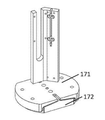
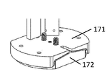
本発明の第1及び第2の態様のいくつかの実施形態では、装置は、スペーサをさらに含む。いくつかの実施形態では、スペーサは、カバーに取り付けられており、カバーと皮膚組織との間に位置決めされており、及び/又は、中空ニードルの挿入の深さを制御するように構成されている。 In some embodiments of the first and second aspects of the invention, the device further comprises a spacer. In some embodiments, the spacer is attached to the cover, positioned between the cover and the skin tissue, and / or configured to control the depth of insertion of the hollow needle. ..
本発明の第1及び第2の態様のいくつかの実施形態では、装置は、皮膚組織の部分を除去すると、アレイパターンを作り出すように構成されている。いくつかの実施形態では、アレイパターンは、一つ以上の列、又は、半ランダムの空間的分布を含む。 In some embodiments of the first and second aspects of the invention, the device is configured to create an array pattern upon removal of a portion of skin tissue. In some embodiments, the array pattern comprises one or more columns, or a semi-random spatial distribution.
本発明の第1及び第2の態様のいくつかの実施形態では、中空ニードルは、繰り返して、皮膚組織の中へ挿入され、皮膚組織から引き抜かれる。 In some embodiments of the first and second aspects of the invention, the hollow needle is repeatedly inserted into and withdrawn from the skin tissue.
本発明の第1及び第2の態様のいくつかの実施形態では、本明細書で説明されているような第1及び/又は第2のプロングは、カールすること(curling)に対して抵抗力がある。 In some embodiments of the first and second aspects of the invention, the first and / or second prongs as described herein are resistant to curling. There is.
第3の態様では、本発明は、皮膚組織の中に美容効果をもたらすための方法を特徴とする。方法は、本明細書で説明されている装置を使用して皮膚組織の中に複数の孔部を作り出すステップを含み、それぞれの孔部は、皮膚組織の一部分を除去することによって作り出される。 In a third aspect, the invention features a method for producing a cosmetic effect in the skin tissue. The method comprises the steps of creating multiple pores in the skin tissue using the devices described herein, each of which is created by removing a portion of the skin tissue.
本発明の第3の態様のいくつかの実施形態では、それぞれの孔部の直径は、約0.14mmと0.84mmとの間にある。いくつかの実施形態では、それぞれの孔部の直径は、約0.24mmと0.40mmとの間にある。 In some embodiments of the third aspect of the invention, the diameter of each hole is between about 0.14 mm and 0.84 mm. In some embodiments, the diameter of each hole is between about 0.24 mm and 0.40 mm.
本発明の第3の態様のいくつかの実施形態では、皮膚組織の除去された部分の表面積割合は、約0.01から約0.65の間にある。いくつかの実施形態では、皮膚組織の除去された部分の表面積割合は、約0.1未満であり、たとえば、約0.01から約0.05の間などにある。いくつかの実施形態では、皮膚組織の除去された部分の表面積割合は、約0.02から約0.03の間にある(たとえば、0.025)。 In some embodiments of the third aspect of the invention, the surface area ratio of the removed portion of the skin tissue is between about 0.01 and about 0.65. In some embodiments, the surface area ratio of the removed portion of the skin tissue is less than about 0.1, for example, between about 0.01 and about 0.05. In some embodiments, the surface area ratio of the removed portion of skin tissue is between about 0.02 and about 0.03 (eg, 0.025).
本発明の第3の態様のいくつかの実施形態では、孔部のうちの少なくとも一つは、(i)真皮層の中へ、(ii)真皮層全体を通って、真皮層と皮下脂肪層との接合部へ、又は、(iii)皮下脂肪層の中へ延在する。いくつかの実施形態では、孔部のうちの少なくとも一つは、約2mmと約5mmとの間の深さまで延在している。 In some embodiments of the third aspect of the invention, at least one of the pores is (i) into the dermis layer, (ii) through the entire dermis layer, the dermis layer and the subcutaneous fat layer. It extends to the junction with or into the (iii) subcutaneous fat layer. In some embodiments, at least one of the holes extends to a depth between about 2 mm and about 5 mm.
本発明の第3の態様のいくつかの実施形態では、一つ以上の列又は半ランダムの空間的分布を含むアレイパターンは、複数の孔部によって発生される。 In some embodiments of the third aspect of the invention, an array pattern containing one or more rows or semi-random spatial distributions is generated by a plurality of pores.
第4の態様では、本発明は、少なくとも第1のプロングを含む少なくとも一つの中空ニードルであって、第1のプロングは、中空ニードルの遠位端に設けられており、第1のプロングの側面と中空ニードルの長手方向軸線との間の角度(α)は、少なくとも約20°であり、中空ニードルが、皮膚組織の中へ挿入され、皮膚組織から引き抜かれるときに、中空ニードルは、皮膚組織の一部分を除去するように構成されている、中空ニードルを提供する。 In a fourth aspect, the invention is at least one hollow needle comprising at least a first prong, the first prong being provided at the distal end of the hollow needle and the side surface of the first prong. The angle (α) between and the longitudinal axis of the hollow needle is at least about 20 °, and when the hollow needle is inserted into and withdrawn from the skin tissue, the hollow needle is in the skin tissue. Provided are hollow needles that are configured to remove a portion of the.
本発明の第4の態様のいくつかの実施形態では、第1のプロングの側面と中空ニードルの長手方向軸線との間の角度(α)は、約20°と約40°との間にある。いくつかの実施形態では、第1のプロングの側面と中空ニードルの長手方向軸線との間の角度(α)は、約30°である。 In some embodiments of the fourth aspect of the invention, the angle (α) between the side surface of the first prong and the longitudinal axis of the hollow needle is between about 20 ° and about 40 °. .. In some embodiments, the angle (α) between the side surface of the first prong and the longitudinal axis of the hollow needle is about 30 °.
本発明の第4の態様のいくつかの実施形態では、中空ニードルは、第2のプロングをさらに含む。いくつかの実施形態では、第2のプロングの側面と中空ニードルの長手方向軸線との間の角度(α)は、少なくとも約20°である。いくつかの実施形態では、第2のプロングの側面と中空ニードルの長手方向軸線との間の角度(α)は、約20°と約40°との間にある。いくつかの実施形態では、第2のプロングの側面と中空ニードルの長手方向軸線との間の角度(α)は、約30°である。本発明の第4の態様のいくつかの実施形態では、第2のプロングの側面と中空ニードルの長手方向軸線との間の角度(α)は、約20°未満である。いくつかの実施形態では、第2のプロングの側面と中空ニードルの長手方向軸線との間の角度(α)は、約5°と約20°との間にある。 In some embodiments of the fourth aspect of the invention, the hollow needle further comprises a second prong. In some embodiments, the angle (α) between the side surface of the second prong and the longitudinal axis of the hollow needle is at least about 20 °. In some embodiments, the angle (α) between the side surface of the second prong and the longitudinal axis of the hollow needle is between about 20 ° and about 40 °. In some embodiments, the angle (α) between the side surface of the second prong and the longitudinal axis of the hollow needle is about 30 °. In some embodiments of the fourth aspect of the invention, the angle (α) between the side surface of the second prong and the longitudinal axis of the hollow needle is less than about 20 °. In some embodiments, the angle (α) between the side surface of the second prong and the longitudinal axis of the hollow needle is between about 5 ° and about 20 °.
本発明の第4の態様のいくつかの実施形態では、第1のプロングは、エッジを含む。いくつかの実施形態では、第1及び第2のプロングのそれぞれが、エッジを含む。 In some embodiments of the fourth aspect of the invention, the first prong comprises an edge. In some embodiments, each of the first and second prongs comprises an edge.
本発明の第4の態様のいくつかの実施形態では、第1のプロングは、平坦な先端を含む。いくつかの実施形態では、第1及び第2のプロングのそれぞれが、平坦な先端を含む。いくつかの実施形態では、平坦な先端は、長さ及び幅を有する。いくつかの実施形態では、長さ及び/又は幅は、中空ニードルの長手方向軸線に対して所定の角度にある。いくつかの実施形態では、長さ及び/又は幅は、中空ニードルの長手方向軸線に対して垂直になっている。 In some embodiments of the fourth aspect of the invention, the first prong comprises a flat tip. In some embodiments, each of the first and second prongs comprises a flat tip. In some embodiments, the flat tip has a length and width. In some embodiments, the length and / or width is at a predetermined angle with respect to the longitudinal axis of the hollow needle. In some embodiments, the length and / or width is perpendicular to the longitudinal axis of the hollow needle.
第5の態様では、本発明は、少なくとも第1のプロングを含む中空ニードルであって、第1のプロングは、中空ニードルの遠位端に設けられており、第1のプロングは、少なくとも二つの寸法を有する平坦な先端を含み、中空ニードルが、皮膚組織の中へ挿入され、皮膚組織から引き抜かれるときに、中空ニードルは、皮膚組織の一部分を除去するように構成されている、中空ニードルを提供する。 In a fifth aspect, the invention is a hollow needle comprising at least a first prong, the first prong being provided at the distal end of the hollow needle and the first prong being at least two. A hollow needle that includes a flat tip with dimensions and is configured to remove a portion of the skin tissue when the hollow needle is inserted into and withdrawn from the skin tissue. offer.
本発明の第5の態様のいくつかの実施形態では、中空ニードルは、第2のプロングをさらに含む。いくつかの実施形態では、第2のプロングは、平坦な先端を含む。いくつかの実施形態では、平坦な先端は、長さ及び幅を有する。いくつかの実施形態では、長さ及び/又は幅は、中空ニードルの長手方向軸線に対して所定の角度にある。いくつかの実施形態では、長さ及び/又は幅は、中空ニードルの長手方向軸線に対して垂直になっている。 In some embodiments of the fifth aspect of the invention, the hollow needle further comprises a second prong. In some embodiments, the second prong comprises a flat tip. In some embodiments, the flat tip has a length and width. In some embodiments, the length and / or width is at a predetermined angle with respect to the longitudinal axis of the hollow needle. In some embodiments, the length and / or width is perpendicular to the longitudinal axis of the hollow needle.
本発明の第5の態様のいくつかの実施形態では、第1のプロングの側面と中空ニードルの長手方向軸線との間の角度(α)は、少なくとも約20°である。いくつかの実施形態では、第1のプロングの側面と中空ニードルの長手方向軸線との間の角度(α)は、約20°と約40°との間にある。いくつかの実施形態では、第1のプロングの側面と中空ニードルの長手方向軸線との間の角度(α)は、約30°である。本発明の第5の態様のいくつかの実施形態では、第1のプロングの側面と中空ニードルの長手方向軸線との間の角度(α)は、約20°未満である。いくつかの実施形態では、第1のプロングの側面と中空ニードルの長手方向軸線との間の角度(α)は、約5°と約20°との間にある。 In some embodiments of the fifth aspect of the invention, the angle (α) between the side surface of the first prong and the longitudinal axis of the hollow needle is at least about 20 °. In some embodiments, the angle (α) between the side surface of the first prong and the longitudinal axis of the hollow needle is between about 20 ° and about 40 °. In some embodiments, the angle (α) between the side surface of the first prong and the longitudinal axis of the hollow needle is about 30 °. In some embodiments of the fifth aspect of the invention, the angle (α) between the side surface of the first prong and the longitudinal axis of the hollow needle is less than about 20 °. In some embodiments, the angle (α) between the side surface of the first prong and the longitudinal axis of the hollow needle is between about 5 ° and about 20 °.
本発明の第5の態様のいくつかの実施形態では、第2のプロングの側面と中空ニードルの長手方向軸線との間の角度(α)は、少なくとも約20°である。いくつかの実施形態では、第2のプロングの側面と中空ニードルの長手方向軸線との間の角度(α)は、約20°と約40°との間にある。いくつかの実施形態では、第2のプロングの側面と中空ニードルの長手方向軸線との間の角度(α)は、約30°である。本発明の第5の態様のいくつかの実施形態では、第2のプロングの側面と中空ニードルの長手方向軸線との間の角度(α)は、約20°未満である。いくつかの実施形態では、第2のプロングの側面と中空ニードルの長手方向軸線との間の角度(α)は、約5°と約20°との間にある。 In some embodiments of the fifth aspect of the invention, the angle (α) between the side surface of the second prong and the longitudinal axis of the hollow needle is at least about 20 °. In some embodiments, the angle (α) between the side surface of the second prong and the longitudinal axis of the hollow needle is between about 20 ° and about 40 °. In some embodiments, the angle (α) between the side surface of the second prong and the longitudinal axis of the hollow needle is about 30 °. In some embodiments of the fifth aspect of the invention, the angle (α) between the side surface of the second prong and the longitudinal axis of the hollow needle is less than about 20 °. In some embodiments, the angle (α) between the side surface of the second prong and the longitudinal axis of the hollow needle is between about 5 ° and about 20 °.
本発明の第5の態様のいくつかの実施形態では、中空ニードルの第1のプロングは、先端マイクロフィーチャを含む。いくつかの実施形態では、中空ニードルの第1及び第2のプロングのそれぞれは、先端マイクロフィーチャを含む。いくつかの実施形態では、先端マイクロフィーチャは、孔部又はスリットである。いくつかの実施形態では、スリットは、矩形形状のスリット、方形形状のスリット、U字形状のスリット、又は、T字形状のスリットである。いくつかの実施形態では、先端マイクロフィーチャは、非垂直の角度で中空ニードルの内壁と交差する。 In some embodiments of the fifth aspect of the invention, the first prong of the hollow needle comprises a tip microfeature. In some embodiments, each of the first and second prongs of the hollow needle comprises a tip microfeature. In some embodiments, the tip microfeature is a hole or slit. In some embodiments, the slit is a rectangular slit, a rectangular slit, a U-shaped slit, or a T-shaped slit. In some embodiments, the tip microfeature intersects the inner wall of the hollow needle at a non-vertical angle.
本発明の第4及び第5の態様のいくつかの実施形態では、中空ニードルは、コーティングによって処理されている。いくつかの実施形態では、コーティングは、TiN、TiCN、TiAlN、ZrN、及びダイヤモンドライクカーボンからなる群から選択される。 In some embodiments of the fourth and fifth aspects of the invention, the hollow needle is treated by coating. In some embodiments, the coating is selected from the group consisting of TiN, TiCN, TiAlN, ZrN, and diamond-like carbon.
本発明の第4及び第5の態様のいくつかの実施形態では、中空ニードルは、繰り返して、皮膚組織の中へ挿入され、皮膚組織から引き抜かれる。 In some embodiments of the fourth and fifth aspects of the invention, the hollow needle is repeatedly inserted into and withdrawn from the skin tissue.
第6の態様では、本発明は、中空ニードル、zアクチュエータ、及び組織除去ツールを含むニードルアセンブリであって、中空ニードルは、中空ニードルの遠位端に設けられた少なくとも第1のプロングを含み、第1のプロングの側面と中空ニードルの長手方向軸線との間の角度(α)は、少なくとも約20°である、ニードルアセンブリを特徴とする。 In a sixth aspect, the invention is a needle assembly comprising a hollow needle, a z-actuator, and a tissue removal tool, wherein the hollow needle comprises at least a first prong provided at the distal end of the hollow needle. The angle (α) between the side surface of the first prong and the longitudinal axis of the hollow needle is at least about 20 °, characterized by a needle assembly.
本発明の第6の態様のいくつかの実施形態では、中空ニードルは、第2のプロングをさらに含む。いくつかの実施形態では、第2のプロングの側面と中空ニードルの長手方向軸線との間の角度(α)は、少なくとも約20°である。いくつかの実施形態では、第2のプロングの側面と中空ニードルの長手方向軸線との間の角度(α)は、約20°未満である。 In some embodiments of the sixth aspect of the invention, the hollow needle further comprises a second prong. In some embodiments, the angle (α) between the side surface of the second prong and the longitudinal axis of the hollow needle is at least about 20 °. In some embodiments, the angle (α) between the side surface of the second prong and the longitudinal axis of the hollow needle is less than about 20 °.
第6の態様のいくつかの実施形態では、第1のプロングは、エッジを含む。いくつかの実施形態では、第1及び第2のプロングのそれぞれが、エッジを含む。いくつかの実施形態では、第1のプロングは、平坦な先端を含む。いくつかの実施形態では、第1及び第2のプロングのそれぞれが、平坦な先端を含む。いくつかの実施形態では、平坦な先端は、長さ及び幅を有する。いくつかの実施形態では、長さ及び/又は幅は、中空ニードルの長手方向軸線に対して所定の角度にある。いくつかの実施形態では、長さ及び/又は幅は、中空ニードルの長手方向軸線に対して垂直になっている。 In some embodiments of the sixth aspect, the first prong comprises an edge. In some embodiments, each of the first and second prongs comprises an edge. In some embodiments, the first prong comprises a flat tip. In some embodiments, each of the first and second prongs comprises a flat tip. In some embodiments, the flat tip has a length and width. In some embodiments, the length and / or width is at a predetermined angle with respect to the longitudinal axis of the hollow needle. In some embodiments, the length and / or width is perpendicular to the longitudinal axis of the hollow needle.
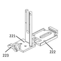
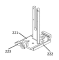
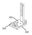
いくつかの実施形態では、本発明の第6の態様のニードルアセンブリは、サポートベース、スキャッフォールド(scaffold)、吸引チューブ、トラップ、及び/又は圧力発生源をさらに含む。いくつかの実施形態では、ニードルアセンブリは、xアクチュエータ及び/又はyアクチュエータに取り外し可能に取り付けられるように構成されている。 In some embodiments, the needle assembly of the sixth aspect of the invention further comprises a support base, a scaffold, a suction tube, a trap, and / or a pressure source. In some embodiments, the needle assembly is configured to be removable from the x-actuator and / or y-actuator.
第7の態様では、本発明は、中空ニードル、zアクチュエータ、及び組織除去ツールを含むニードルアセンブリであって、中空ニードルは、中空ニードルの遠位端に設けられた少なくとも第1のプロングを含み、第1のプロングは、少なくとも二つの寸法を有する平坦な先端を含む、ニードルアセンブリを特徴とする。 In a seventh aspect, the invention is a needle assembly comprising a hollow needle, a z-actuator, and a tissue removal tool, wherein the hollow needle comprises at least a first prong provided at the distal end of the hollow needle. The first prong features a needle assembly that includes a flat tip with at least two dimensions.
第7の態様のいくつかの実施形態では、中空ニードルは、第2のプロングをさらに含む。いくつかの実施形態では、第2のプロングは、平坦な先端を含む。いくつかの実施形態では、平坦な先端は、長さ及び幅を有する。いくつかの実施形態では、長さ及び/又は幅は、中空ニードルの長手方向軸線に対して所定の角度にある。いくつかの実施形態では、長さ及び/又は幅は、中空ニードルの長手方向軸線に対して垂直になっている。 In some embodiments of the seventh aspect, the hollow needle further comprises a second prong. In some embodiments, the second prong comprises a flat tip. In some embodiments, the flat tip has a length and width. In some embodiments, the length and / or width is at a predetermined angle with respect to the longitudinal axis of the hollow needle. In some embodiments, the length and / or width is perpendicular to the longitudinal axis of the hollow needle.
第7の態様のいくつかの実施形態では、第1のプロングの側面と中空ニードルの長手方向軸線との間の角度(α)は、少なくとも約20°である。いくつかの実施形態では、第1のプロングの側面と中空ニードルの長手方向軸線との間の角度(α)は、約20°未満である。第7の態様のいくつかの実施形態では、第2のプロングの側面と中空ニードルの長手方向軸線との間の角度(α)は、少なくとも約20°である。いくつかの実施形態では、第2のプロングの側面と中空ニードルの長手方向軸線との間の角度(α)は、約20°未満である。 In some embodiments of the seventh aspect, the angle (α) between the side surface of the first prong and the longitudinal axis of the hollow needle is at least about 20 °. In some embodiments, the angle (α) between the side surface of the first prong and the longitudinal axis of the hollow needle is less than about 20 °. In some embodiments of the seventh aspect, the angle (α) between the side surface of the second prong and the longitudinal axis of the hollow needle is at least about 20 °. In some embodiments, the angle (α) between the side surface of the second prong and the longitudinal axis of the hollow needle is less than about 20 °.
いくつかの実施形態では、本発明の第7の態様のニードルアセンブリは、サポートベース、スキャッフォールド、吸引チューブ、トラップ、及び/又は圧力発生源をさらに含む。いくつかの実施形態では、ニードルアセンブリは、xアクチュエータ及び/又はyアクチュエータに取り外し可能に取り付けられるように構成されている。 In some embodiments, the needle assembly of the seventh aspect of the invention further comprises a support base, a scaffold, a suction tube, a trap, and / or a pressure source. In some embodiments, the needle assembly is configured to be removable from the x-actuator and / or y-actuator.
定義
「組織部分」とは、(たとえば、プラグとして)装置の中空ニードルによって除去される皮膚及び/又は近位組織層(たとえば、表皮層、真皮層、及び皮下脂肪層)のその部分を意味する。組織部分は、本発明の装置の中空ニードルの特定の寸法、幾何学形状、及び他の性質に対応する、特定の寸法、幾何学形状、及び他の性質を有することが可能である。
Definition "Tissue portion" means that portion of the skin and / or proximal tissue layer (eg, epidermal layer, dermis layer, and subcutaneous adipose layer) that is removed by the hollow needle of the device (eg, as a plug). .. Tissue portions can have specific dimensions, geometry, and other properties that correspond to the specific dimensions, geometry, and other properties of the hollow needles of the device of the invention.
「実質的に損傷を受けていない」組織部分の除去とは、中空ニードルのルーメンから除去される組織部分が破壊されていない又は一体となった組織部分として残っていることを意味しており、すなわち、除去された組織部分が、個々のより小さい部片へと破壊若しくは分離されていないか又はばらされていないことを意味する。 Removal of "substantially undamaged" tissue parts means that the tissue parts removed from the lumen of the hollow needle remain unbroken or united tissue parts. That is, it means that the removed tissue portion is not broken, separated or disassembled into individual smaller pieces.
「約」とは、記載されている値の±10%を意味する。 By "about" is meant ± 10% of the stated value.
「被験者」とは、哺乳類(たとえば、人間、又は、人間以外の哺乳類)を意味する。 "Subject" means a mammal (eg, a human or non-human mammal).
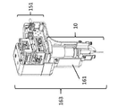
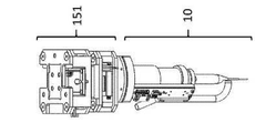
「近位」又は「近位端」とは、ニードル先端から離れているか又はニードル先端の反対側にある中空ニードルの端部、たとえば、図1A〜図1Fに示されているように、zアクチュエータ12及びサポートベース11により近い中空ニードル14の端部(基端部)を意味する。
A "proximal" or "proximal end" is the end of a hollow needle that is away from or opposite the needle tip, eg, the z-actuator, as shown in FIGS. 1A-1F. It means the end portion (base end portion) of the
「遠位」又は「遠位端」とは、ニードル先端(たとえば、図1A〜図1Fのニードル先端18)にあるか又はその近くにある、中空ニードルの端部(末端部)を意味する。
"Distal" or "distal end" means the end (end) of a hollow needle at or near the needle tip (eg,
「コアリングレート」とは、中空ニードルの作動の合計数に対する、治療エリアからのコアリングされた組織の除去を結果として生じさせる中空ニードルの作動のパーセンテージを意味する。本発明の中空ニードルは、コアリングレートを最大化するように設計されており、また、コアリングされる組織の除去を結果として生じさせない中空ニードルの作動を最小化するように設計されている。組織部分は、コアリング力が組織抵抗力を超えるときに、皮膚から外れる。組織抵抗力は、その周囲の組織への組織部分の接続によって決定される。たとえば、中空ニードルが皮膚の真皮層を通して完全に挿入されるときに、組織抵抗力は、ニードルのルーメンの中の組織部分と皮下脂肪層との間の接続によって決定される。コアリングレートは、たとえば、中空ニードルのコアリング力、中空ニードルのルーメン壁部と組織部分との間の摩擦、及び組織抵抗力によって決定される。また、コアリングレートは、中空ニードルを横切って圧力差を印加することによって影響を及ぼされ得る。たとえば、中空ニードルの近位端に印加される真空は、コアリングされた組織部分を中空ニードルから吸引することが可能であり、それによって、コアリングレートを増加させる。 "Coring rate" means the percentage of hollow needle activation resulting from the removal of coraled tissue from the treatment area to the total number of hollow needle activations. The hollow needles of the present invention are designed to maximize the coring rate and also to minimize the operation of the hollow needles that do not result in the removal of the coraled tissue. The tissue portion detaches from the skin when the coring force exceeds the tissue resistance. Tissue resistance is determined by the connection of the tissue portion to the surrounding tissue. For example, when a hollow needle is completely inserted through the dermis layer of the skin, tissue resistance is determined by the connection between the tissue portion in the lumen of the needle and the subcutaneous fat layer. The coring rate is determined, for example, by the coring force of the hollow needle, the friction between the lumen wall and the tissue portion of the hollow needle, and the tissue resistance. Also, the coring rate can be affected by applying a pressure difference across the hollow needle. For example, the vacuum applied to the proximal end of the hollow needle can aspirate the cored tissue portion from the hollow needle, thereby increasing the coring rate.
「コアリング力」とは、ニードルが皮膚から引き抜かれているときに、コアリングされた組織部分に装置の中空ニードルによって印加される力を意味する。コアリング力は、たとえば、ニードルが皮膚から引き抜かれているときの中空ニードルのルーメン壁部とコアリングされた組織部分との間の摩擦、並びに、中空ニードルの中のマイクロフィーチャの位置、幾何学形状、及び配向によって決定される。 "Corring force" means the force applied by the hollow needle of the device to the cored tissue portion when the needle is pulled out of the skin. The coring force is, for example, the friction between the lumen wall of the hollow needle and the coraled tissue when the needle is pulled out of the skin, as well as the position and geometry of the microfeatures in the hollow needle. Determined by shape and orientation.
「挿入力」とは、中空ニードルが皮膚の中へ挿入されるときに、中空ニードルによって皮膚の上に発生される力を意味する。挿入力は、組織を突き通すために必要とされる量によって最初に決定される。組織が突き通されると、挿入力は、ニードル壁部(内側及び外側)と周囲の組織との間の摩擦、並びに、ニードルの先端において組織を分離するために必要とされる力によって決定される。 "Insert force" means the force generated on the skin by the hollow needle as it is inserted into the skin. Insertion force is initially determined by the amount required to penetrate the tissue. Once the tissue is pierced, the insertion force is determined by the friction between the needle wall (inside and outside) and the surrounding tissue, as well as the force required to separate the tissue at the tip of the needle. NS.
本発明の他の特徴及び利点は、以下の詳細な説明及び特許請求の範囲から明らかになることになる。 Other features and advantages of the present invention will become apparent from the following detailed description and claims.
本発明は、皮膚から組織部分を除去することによって、皮膚の中に美容効果(たとえば、組織体積を排除する、皮膚を引き締める、及び/又は、皮膚弛緩を低減させる)を発生させるための中空ニードル、ニードルアセンブリ、作動ユニット、装置、キット、及び方法に関する。理論に拘束されることなく、このアプローチは、皮膚組織の大部分を除去することによって、及び、組織リサーフェシング及びリモデリングに貢献する生物学的な反応をトリガすることによって、皮膚リモデリングを促進する。とりわけ、本発明は、皮膚の中への挿入及び皮膚からの引き抜きの後に、中空ニードルのルーメンの内側に組織部分を捕獲及び保持することによって、組織部分をコアリングすることができる、中空ニードル、並びに、関連のニードルアセンブリ、装置、キット、及び方法に関する。コアリングされた組織部分は、中空ニードルのルーメンから除去され、処分され得る。プロセスは、とりわけ、皮膚の所望のエリアにわたって、また、被験者の身体の選ばれた部位に位置付けされて、複数のコアリングされた皮膚組織部分を発生させるために繰り返され得る。本明細書で説明されている中空ニードル、ニードルアセンブリ、作動ユニット、装置、キット、及び方法は、利便性、手頃な価格であること、及び、組織回復を望む患者へのアクセスのしやすさを維持しながら、現在の利用可能な装置及び技法を上回る有効性の増加を提供する。 The present invention is a hollow needle for producing a cosmetic effect in the skin (eg, eliminating tissue volume, tightening the skin, and / or reducing cutis laxa) by removing tissue portions from the skin. , Needle assembly, actuation unit, device, kit, and method. Without being bound by theory, this approach facilitates skin remodeling by removing most of the skin tissue and by triggering biological reactions that contribute to tissue resurfacing and remodeling. .. Among other things, the invention is a hollow needle, which is capable of coring the tissue portion by capturing and retaining the tissue portion inside the lumen of the hollow needle after insertion into and withdrawal from the skin. Also related to related needle assemblies, devices, kits, and methods. The coreded tissue portion can be removed from the lumen of the hollow needle and disposed of. The process can be repeated, among other things, over a desired area of skin and at selected sites of the subject's body to generate multiple coreded skin tissue portions. The hollow needles, needle assemblies, actuation units, devices, kits, and methods described herein are convenient, affordable, and accessible to patients who desire tissue recovery. While maintaining, it provides increased efficacy over currently available equipment and techniques.
ニードル
本発明の装置は、少なくとも第1のプロングを有する少なくとも一つの中空ニードルを含む。いくつかの実施形態では、プロングの側面と中空ニードルの長手方向軸線との間の角度(たとえば、ベベル角度α)は、少なくとも約20°である(たとえば、ベベル角度αは、約20°よりも大きいことが可能であり、たとえば、20°、22°、24°、26°、28°、30°、32°、34°、36°、38°、及び40°などよりも大きいことが可能であり、又は、約20°から約40°の角度であり、20°から40°の間、20°から38°の間、20°から36°の間、20°から34°の間、20°から32°の間、20°から30°の間、20°から28°の間、20°から26°の間、20°から24°の間、20°から22°の間、22°から40°の間、24°から40°の間、26°から40°の間、28°から40°の間、30°から40°の間、32°から40°の間、34°から40°の間、36°から40°の間、及び、38°から40°の間の角度であることが可能である)。とりわけ、プロングの側面と中空ニードルの長手方向軸線との間の角度(たとえば、ベベル角度α)は、約30°である。
Needles The device of the invention includes at least one hollow needle with at least a first prong. In some embodiments, the angle between the sides of the prong and the longitudinal axis of the hollow needle (eg, bevel angle α) is at least about 20 ° (eg, bevel angle α is greater than about 20 °). Can be larger, eg, larger than 20 °, 22 °, 24 °, 26 °, 28 °, 30 °, 32 °, 34 °, 36 °, 38 °, and 40 °. Yes, or an angle of about 20 ° to about 40 °, between 20 ° and 40 °, between 20 ° and 38 °, between 20 ° and 36 °, between 20 ° and 34 °, 20 °. From 32 °, 20 ° to 30 °, 20 ° to 28 °, 20 ° to 26 °, 20 ° to 24 °, 20 ° to 22 °, 22 ° to 40 Between °, between 24 ° and 40 °, between 26 ° and 40 °, between 28 ° and 40 °, between 30 ° and 40 °, between 32 ° and 40 °, between 34 ° and 40 °. The angle can be between 36 ° and 40 °, and between 38 ° and 40 °). In particular, the angle between the sides of the prong and the longitudinal axis of the hollow needle (eg, bevel angle α) is about 30 °.
いくつかの実施形態では、中空ニードルのプロングの先端は、エッジである。いくつかの実施形態では、中空ニードルのプロングの先端は、少なくとも二つの寸法を有する平坦な先端である。いくつかの実施形態では、中空ニードルのプロングは、先端マイクロフィーチャを含む。本発明の中空ニードルは、ニードル先端がカールすること及び擦り切れ(たとえば、鈍くなるこt)、ニードルヒール部の劣化、並びにニードル曲げなどのような、使用の間の頻繁に起こるニードル損傷を防止するために構築される。本発明の中空ニードルは、多数の作動サイクル(たとえば、1,000、2,000、3,000、4,000、5,000、6,000、7,000、8,000、9,000、1,0000、11,000、12,000、13,000、14,000、15,000、又は20,000を上回る作動サイクル)にわたって、機械的な完全性及び耐久性を維持するように設計されている。また、好ましくは、これらのニードルは、高いコアリングレートで皮膚から組織部分を効果的に除去する。皮膚組織の中に美容効果をもたらすために、装置の中空ニードルは、好ましくは、事前決定された力を使用して、事前決定された深さまで、皮膚組織の中へ挿入され、中空ニードルのルーメンの中の皮膚組織の部分を捕獲することによって、中空ニードルが皮膚組織の一部分を除去するようになっている。 In some embodiments, the tip of the prong of the hollow needle is an edge. In some embodiments, the tip of the prong of the hollow needle is a flat tip with at least two dimensions. In some embodiments, the hollow needle prong comprises a tip microfeature. The hollow needle of the present invention prevents frequent needle damage during use, such as curling and fraying of the needle tip (eg, dullness), deterioration of the needle heel, and needle bending. Built for. The hollow needle of the present invention has a large number of operating cycles (eg, 1,000, 2,000, 3,000, 4,000, 5,000, 6,000, 7,000, 8,000, 9,000, Designed to maintain mechanical integrity and durability over 10000, 11,000, 12,000, 13,000, 14,000, 15,000, or operating cycles greater than 20,000) ing. Also preferably, these needles effectively remove tissue portions from the skin at high coring rates. To bring a cosmetic effect into the skin tissue, the hollow needle of the device is preferably inserted into the skin tissue to a predetermined depth using a predetermined force and the lumen of the hollow needle. By capturing a portion of the skin tissue within, the hollow needle is adapted to remove a portion of the skin tissue.
プロング
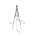
図2に示されているように、装置の中空ニードルの遠位端20(たとえば、皮膚組織を突き通すニードルの端部)は、一つ以上のプロング21を形成するように形状決めされ得る。装置の中空ニードルは、遠位端において、一つのプロング、二つのプロング、又は、三つ以上のプロング(たとえば、三つ、四つ、五つ、又は六つのプロング)を有することが可能である。一つのプロングを有する中空ニードルは、中空ニードルの遠位端の一方の側部を、中空ニードルの長手方向軸線に対して所定の角度で研削することによって形成され得る。二つのプロングを有する中空ニードルは、中空ニードルの遠位端の両方の側部を、中空ニードルの長手方向軸線に対して所定の角度で研削することによって形成され得る。
Prongs As shown in FIG. 2, the
中空ニードルの遠位端におけるプロングの幾何学形状は、ベベル角度によって特徴付けられ得る。ベベル角度、たとえば、図3に示されているような角度αは、プロングの側面31と中空ニードルの長手方向軸線32との間の角度を表している。「2α」の角度は、中空ニードルのプロングの二つの側面の間の角度、たとえば、中空ニードルの側面31と側面33との間の角度を表している。プロングの側面と中空ニードルの長手方向軸線との間のベベル角度αは、少なくとも約20°(たとえば、約20°と約40°との間(たとえば、20、22、24、26、28、30、32、34、36、38、又は40°))であることが可能である。とりわけ、プロングの側面と中空ニードルの長手方向軸線との間の角度は、約30°であることが可能である。二つ以上のプロングを有する中空ニードル(たとえば、図2)に関して、それぞれのプロングは、同じベベル角度又は異なるベベル角度を有することが可能である。一つの実施形態では、二つのプロング、たとえば、第1のプロング及び第2のプロングを有する中空ニードルに関して、第1のプロングの側面と中空ニードルの長手方向軸線との間の角度は、約20°と約30°との間(たとえば、20、22、24、26、28、又は30°)にあることが可能であり、第2のプロングの側面と中空ニードルの長手方向軸線との間の角度は、約30°と約40°との間(たとえば、30、32、34、36、38、又は30°)にあることが可能である。たとえば、第1のプロングは、20°のベベル角度αを有することが可能であり、第2のプロングは、30°のベベル角度αを有することが可能である。
The geometry of the prong at the distal end of the hollow needle can be characterized by the bevel angle. The bevel angle, eg, the angle α as shown in FIG. 3, represents the angle between the
少なくとも約20°以上のベベル角度αは、皮膚組織の中への挿入及び引き抜きのいくつかの作動サイクルにわたって、ニードルの機械的な完全性を改善する。下記の表1は、40°の2αベベル角度を有する2プロングの中空ニードル(それぞれのプロングのベベル角度αは、20°である)が、20°の2αベベル角度を有する2プロングの中空ニードル(それぞれのプロングのベベル角度αは、10°である)に対して、ニードル先端がカールすることの発生を低減させることを示している。10°のベベル角度αをそれぞれ有する合計で五つの2プロングの中空ニードル、及び、20°のベベル角度αをそれぞれ有する五つの2プロングの中空ニードルがテストされた。 A bevel angle α of at least about 20 ° or more improves the mechanical integrity of the needle over several working cycles of insertion and withdrawal into the skin tissue. Table 1 below shows a two-prong hollow needle with a 2α bevel angle of 40 ° (the bevel angle α of each prong is 20 °) and a two-prong hollow needle with a 2α bevel angle of 20 ° (the bevel angle α of each prong is 20 °). The bevel angle α of each prong is 10 °), indicating that the occurrence of curling of the needle tip is reduced. A total of five two-prong hollow needles, each with a 10 ° bevel angle α, and five two-prong hollow needles, each with a 20 ° bevel angle α, were tested.

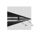
中空ニードルのプロングの先端は、さまざまな幾何学形状のものであることが可能である。たとえば、プロングの先端は、尖端(たとえば、図5Aに示されているような尖端51)又はエッジ(たとえば、1次元のエッジ)(たとえば、図5Bに示されているようなエッジ52)を有することが可能である。先端にエッジを有するプロングに関して、プロングのベベル角度のそれぞれは、少なくとも約20°(たとえば、約20°から約40°(たとえば、約30°))であることが可能である。二つ以上のプロング、たとえば、二つのプロングを有する中空ニードルに関して、プロングは、異なるベベル角度を有することが可能である(たとえば、第1のプロングにおいて、約20°のベベル角度α、及び、第2のプロングにおいて、約30°のベベル角度α)。プロングの先端は、平坦な先端(たとえば、二つの寸法を有する平坦な先端)(たとえば、図5Cに示されているような平坦な先端53)であることが可能である。たとえば、平坦な先端は、長さ及び幅を有している。プロングの平坦な先端の表面(長さ/幅)は、中空ニードルの長手方向軸線に対して所定の角度になっていることが可能である。たとえば、平坦な先端の表面は、中空ニードルの長手方向軸線に対して垂直になっていることが可能であり(たとえば、中空ニードルの長手方向軸線に対して90°の角度になっている)、又は、平坦な先端の表面は、中空ニードルの長手方向軸線に対して非90°の角度になっていることが可能である(たとえば、約3°から約89°の間、たとえば、3°から89°など、たとえば、3、6、9、12、15、18、21、24、27、30、33、36、39、42、45、48、51、54、57、60、63、66、69、72、75、78、81、84、87、及び89°)。平坦な先端の表面は、レベルであることが可能であり、又は、異なる幾何学形状、たとえば、円弧、溝部、若しくは凹凸などを有することが可能である。2次元の平坦な先端を有するプロングに関して、プロングのベベル角度のそれぞれは、約2°から約40°の間にあることが可能である(たとえば、2、4、6、8、10、12、14、16、18、20、22、24、26、28、30、32、34、36、38、又は40°)。ニードルは、それぞれが2次元の平坦な先端を備えた一つ又は二つのプロングを有することが可能であり、そこでは、プロングの一つ又は両方が、少なくとも約20°(たとえば、約20°から約40°(たとえば、約30°))のベベル角度αを有している。1次元のエッジ又は2次元の平坦な先端を有するニードルは、ニードル先端がカールすることの可能性の低減を示す。
The tip of the prong of the hollow needle can be of various geometric shapes. For example, the tip of the prong has a tip (eg, a
ゲージ、内径、及び長さ
本発明の装置の中空ニードルは、18から30のゲージ(たとえば、18、19、20、21、22、23、24、25、26、27、28、29、及び30ゲージ)を含む、任意のゲージのものであることが可能である。中空ニードルのゲージは、22から25であることが可能である(たとえば、22、23、24、及び25ゲージ)。装置の中空ニードルは、約0.14mmから約0.84mmの内径を有することが可能である(たとえば、0.14、0.15、0.16、0.17、0.18、0.19、0.2、0.21、0.22、0.23、0.24、0.25、0.26、0.27、0.28、0.29、0.3、0.31、0.32、0.33、0.34、0.35、0.36、0.37、0.38、0.39、0.4、0.41、0.42、0.43、0.44、0.45、0.46、0.47、0.48、0.49、0.5、0.51、0.52、0.53、0.54、0.55、0.56、0.57、0.58、0.59、0.6、0.61、0.62、0.63、0.64、0.65、0.66、0.67、0.68、0.69、0.7、0.71、0.72、0.73、0.74、0.75、0.76、0.77、0.78、0.79、0.8、0.81、0.82、0.83、及び0.84mm)。中空ニードルの内径は、中空ニードルの内側ルーメンの直径を表している。中空ニードルの内径は、約0.24mmから約0.40mm(たとえば、0.24、0.25、0.26、0.27、0.28、0.29、0.3、0.31、0.32、0.33、0.34、0.35、0.36、0.37、0.38、0.39、及び0.4mm)であることが可能である。したがって、装置の中空ニードルによって除去される皮膚組織の一部分(たとえば、コアリングされる組織部分)の直径は、一般的に、中空ニードルの内径に対応している。
Gauges, Inner Diameter, and Length The hollow needles of the device of the invention are 18 to 30 gauges (eg, 18, 19, 20, 21, 22, 23, 24, 25, 26, 27, 28, 29, and 30). It can be of any gauge, including gauges). The gauge of the hollow needle can be 22 to 25 (eg, 22, 23, 24, and 25 gauges). The hollow needle of the device can have an inner diameter of about 0.14 mm to about 0.84 mm (eg, 0.14, 0.15, 0.16, 0.17, 0.18, 0.19). , 0.2, 0.21, 0.22, 0.23, 0.24, 0.25, 0.26, 0.27, 0.28, 0.29, 0.3, 0.31, 0 .32, 0.33, 0.34, 0.35, 0.36, 0.37, 0.38, 0.39, 0.4, 0.41, 0.42, 0.43, 0.44 , 0.45, 0.46, 0.47, 0.48, 0.49, 0.5, 0.51, 0.52, 0.53, 0.54, 0.55, 0.56, 0 .57, 0.58, 0.59, 0.6, 0.61, 0.62, 0.63, 0.64, 0.65, 0.66, 0.67, 0.68, 0.69 , 0.7, 0.71, 0.72, 0.73, 0.74, 0.75, 0.76, 0.77, 0.78, 0.79, 0.8, 0.81, 0 .82, 0.83, and 0.84 mm). The inner diameter of the hollow needle represents the diameter of the inner lumen of the hollow needle. The inner diameter of the hollow needle is from about 0.24 mm to about 0.40 mm (eg, 0.24, 0.25, 0.25, 0.27, 0.28, 0.29, 0.3, 0.31, 0.31. It can be 0.32, 0.33, 0.34, 0.35, 0.36, 0.37, 0.38, 0.39, and 0.4 mm). Therefore, the diameter of a portion of skin tissue removed by the device's hollow needle (eg, the coring tissue portion) generally corresponds to the inner diameter of the hollow needle.
いくつかの実施形態では、中空ニードルの外径及び/又は内径は、その長さとともに変化することが可能であり、中空ニードルの一つの領域の直径が、同じニードルの別の領域の外径及び/又は内径とは異なることができるようになっている。中空ニードルにわたる直径の変化は、連続的であってもよく、又は、連続的でなくてもよい。中空ニードルは、完全に円筒形状であってもよく、又は、完全に円筒形状でなくてもよい。たとえば、一つ以上の中空ニードルは、一つ以上の寸法に関して、その長さのいくつか又はすべてに沿って、矩形、鋸歯状の、スカロップト形状、及び/又は不規則になっていてもよい。いくつかの実施形態では、内側ルーメン直径は、中空ニードルの長さに沿って変化することが可能である。また、本発明は、少なくとも20°(たとえば、約20°と約40°との間(たとえば、20、22、24、26、28、30、32、34、36、38、又は40°))のベベル角度αを有するスエージ加工された中空ニードル、及び、その長さにわたる可変の内側ルーメン直径を特徴とする。図5D及び図5Eは、中空ニードルの遠位端の近く(たとえば、皮膚組織を突き通すニードルの端部の近く)においてより小さい直径を有する、スエージ加工された中空ニードル54を示している。図5Dは、スエージ加工された中空ニードル54の外側を示しており、図5Eは、スエージ加工された中空ニードル54の長手方向の断面を示している。他の実施形態では、内径は、中空ニードルの近位端において(たとえば、皮膚を突き通す先端から離れて)、より幅広くなっていることが可能である。これは、中空ニードルからのコアリングされる組織部分の除去を促進することが可能であり、中空ニードルの清掃に対する必要性を限定することが可能であり、ニードル閉塞の発生を低減させることが可能である。
In some embodiments, the outer and / or inner diameter of the hollow needle can vary with its length, with the diameter of one region of the hollow needle being the outer diameter and / or inner diameter of another region of the same needle. / Or can be different from the inner diameter. The change in diameter across the hollow needle may or may not be continuous. The hollow needle may or may not be completely cylindrical. For example, one or more hollow needles may be rectangular, serrated, scalloped, and / or irregular along some or all of their length with respect to one or more dimensions. In some embodiments, the inner lumen diameter can vary along the length of the hollow needle. Also, the invention is at least 20 ° (eg, between about 20 ° and about 40 ° (eg, 20, 22, 24, 26, 28, 30, 32, 34, 36, 38, or 40 °)). It features a swaged hollow needle with a bevel angle α and a variable inner lumen diameter over its length. 5D and 5E show a swaged
装置の中空ニードルは、さまざまな長さのものであることが可能であり、また、さまざまな有効長さ(たとえば、皮膚組織を突き通すように構成されている中空ニードルの長さ)を有することが可能である。有効長さは、約0.5mmから約10mm(たとえば、0.5、0.6、0.8、1、1.2、1.4、1.6、1.8、2、2.2、2.4、2.6、2.8、3、3.2、3.4、3.6、3.8、4、4.2、4.4、4.6、4.8、5、5.2、5.4、5.6、5.8、6、6.2、6.4、6.6、6.8、7、7.2、7.4、7.6、7.8、8、8.2、8.4、8.6、8.8、9、9.2、9.4、9.6、9.8、及び10mm)まで変化することが可能であり、また、手動制御又は自動的な制御によって選択可能であり得る(たとえば、スクロールホイール、又は、電磁アクチュエータなどのような作動機構)。中空ニードルの有効長さは、治療を必要とする皮膚エリアに応じて、調節及び選択され得る。たとえば、約0.5mmから約2mm(たとえば、0.5、0.6、0.8、1、1.2、1.4、1.6、1.8、及び2mm)の有効長さを有する中空ニードルは、薄い皮膚、たとえば、まぶたの皮膚を治療するために使用され得る。まぶたの皮膚の表皮層及び真皮層の厚さは、約0.5mmから約1mm(たとえば、0.5、0.6、0.8、及び1)である可能性がある。約5mmから約10mm(たとえば、5、6、7、8、9、及び10mm)の有効長さを有する中空ニードルは、厚い皮膚、たとえば、背中の皮膚又は瘢痕組織などを治療するために使用され得、厚い皮膚は、健康な皮膚組織よりも厚くなっている可能性がある。皮膚の表皮層の厚さは、約0.05mmから約2mm(たとえば、0.05から2mm、0.05mmから1.95mm、0.05mmから1.9mm、0.05mmから1.85mm、0.05mmから1.8mm、0.05mmから1.75mm、0.05mmから1.7mm、0.05mmから1.65mm、0.05mmから1.6mm、0.05mmから1.55mm、0.05mmから1.5mm、0.05mmから1.45mm、0.05mmから1.4mm、0.05mmから1.35mm、0.05mmから1.3mm、0.05mmから1.25mm、0.05mmから1.2mm、0.05mmから1.15mm、0.05mmから1.1mm、0.05mmから1.05mm、0.05mmから1mm、0.05mmから0.95mm、0.05mmから0.9mm、0.05mmから0.85mm、0.05mmから0.8mm、0.05mmから0.75mm、0.05mmから0.7mm、0.05mmから0.65mm、0.05mmから0.6mm、0.05mmから0.55mm、0.05mmから0.5mm、0.05mmから0.45mm、0.05mmから0.4mm、0.05mmから0.35mm、0.05mmから0.3mm、0.05mmから0.25mm、0.05mmから0.2mm、0.05mmから0.15mm、0.05mmから0.1mm、0.1mmから2mm、0.15mmから2mm、0.2mmから2mm、0.25mmから2mm、0.3mmから2mm、0.35mmから2mm、0.4mmから2mm、0.45mmから2mm、0.5mmから2mm、0.55mmから2mm、0.6mmから2mm、0.65mmから2mm、0.7mmから2mm、0.75mmから2mm、0.8mmから2mm、0.85mmから2mm、0.9mmから2mm、0.95mmから2mm、1mmから2mm、1.05mmから2mm、1.15mmから2mm、1.2mmから2mm、1.25mmから2mm、1.3mmから2mm、1.35mmから2mm、1.4mmから2mm、1.45mmから2mm、1.5mmから2mm、1.55mmから2mm、1.6mmから2mm、1.65mmから2mm、1.7mmから2mm、1.75mmから2mm、1.8mmから2mm、1.85mmから2mm、1.9mmから2mm、及び1.95mmから2mm)である可能性がある。皮膚の真皮層の厚さは、2mmから8mm(たとえば、2mmから8mm、2mmから7.5mm、2mmから7mm、2mmから6.5mm、2mmから6mm、2mmから5.5mm、2mmから5mm、2mmから4.5mm、2mmから4mm、2mmから3.5mm、2mmから3mm、2mmから2.5mm、2.5mmから8mm、3mmから8mm、3.5mmから8mm、4mmから8mm、4.5mmから8mm、5mmから8mm、5.5mmから8mm、6mmから8mm、6.5mmから8mm、7mmから8mm、及び7.5mmから8mm)である可能性がある。中空ニードルの有効長さは、皮膚の表皮層及び/又は真皮層を突き通すために調節及び選択され得る。 The hollow needles of the device can be of various lengths and can have different effective lengths (eg, the length of the hollow needle configured to penetrate the skin tissue). It is possible. Effective lengths range from about 0.5 mm to about 10 mm (eg 0.5, 0.6, 0.8, 1, 1.2, 1.4, 1.6, 1.8, 2, 2.2). , 2.4, 2.6, 2.8, 3, 3.2, 3.4, 3.6, 3.8, 4, 4.2, 4.4, 4.6, 4.8, 5 5.2, 5.4, 5.6, 5.8, 6, 6.2, 6.4, 6.6, 6.8, 7, 7.2, 7.4, 7.6, 7 It is possible to change to 8.8, 8, 8.2, 8.4, 8.6, 8.8, 9, 9.2, 9.4, 9.6, 9.8, and 10 mm). Also, it may be selectable by manual control or automatic control (eg, an actuating mechanism such as a scroll wheel or an electromagnetic actuator). The effective length of the hollow needle can be adjusted and selected depending on the skin area in need of treatment. For example, an effective length of about 0.5 mm to about 2 mm (eg 0.5, 0.6, 0.8, 1, 1.2, 1.4, 1.6, 1.8, and 2 mm). Hollow needles with have can be used to treat thin skin, eg eyelid skin. The thickness of the epidermal and dermis layers of the eyelid skin can be from about 0.5 mm to about 1 mm (eg, 0.5, 0.6, 0.8, and 1). Hollow needles with an effective length of about 5 mm to about 10 mm (eg, 5, 6, 7, 8, 9, and 10 mm) are used to treat thick skin, such as back skin or scar tissue. Obtained, thick skin may be thicker than healthy skin tissue. The thickness of the epidermal layer of the skin is from about 0.05 mm to about 2 mm (eg, 0.05 to 2 mm, 0.05 mm to 1.95 mm, 0.05 mm to 1.9 mm, 0.05 mm to 1.85 mm, 0). 0.05 mm to 1.8 mm, 0.05 mm to 1.75 mm, 0.05 mm to 1.7 mm, 0.05 mm to 1.65 mm, 0.05 mm to 1.6 mm, 0.05 mm to 1.55 mm, 0.05 mm From 1.5 mm, 0.05 mm to 1.45 mm, 0.05 mm to 1.4 mm, 0.05 mm to 1.35 mm, 0.05 mm to 1.3 mm, 0.05 mm to 1.25 mm, 0.05 mm to 1 .2 mm, 0.05 mm to 1.15 mm, 0.05 mm to 1.1 mm, 0.05 mm to 1.05 mm, 0.05 mm to 1 mm, 0.05 mm to 0.95 mm, 0.05 mm to 0.9 mm, 0 0.05 mm to 0.85 mm, 0.05 mm to 0.8 mm, 0.05 mm to 0.75 mm, 0.05 mm to 0.7 mm, 0.05 mm to 0.65 mm, 0.05 mm to 0.6 mm, 0.05 mm From 0.55 mm, 0.05 mm to 0.5 mm, 0.05 mm to 0.45 mm, 0.05 mm to 0.4 mm, 0.05 mm to 0.35 mm, 0.05 mm to 0.3 mm, 0.05 mm to 0 .25 mm, 0.05 mm to 0.2 mm, 0.05 mm to 0.15 mm, 0.05 mm to 0.1 mm, 0.1 mm to 2 mm, 0.15 mm to 2 mm, 0.2 mm to 2 mm, 0.25 mm to 2 mm , 0.3 mm to 2 mm, 0.35 mm to 2 mm, 0.4 mm to 2 mm, 0.45 mm to 2 mm, 0.5 mm to 2 mm, 0.55 mm to 2 mm, 0.6 mm to 2 mm, 0.65 mm to 2 mm, 0 .7 mm to 2 mm, 0.75 mm to 2 mm, 0.8 mm to 2 mm, 0.85 mm to 2 mm, 0.9 mm to 2 mm, 0.95 mm to 2 mm, 1 mm to 2 mm, 1.05 mm to 2 mm, 1.15 mm to 2 mm , 1.2 mm to 2 mm, 1.25 mm to 2 mm, 1.3 mm to 2 mm, 1.35 mm to 2 mm, 1.4 mm to 2 mm, 1.45 mm to 2 mm, 1.5 mm to 2 mm, 1.55 mm to 2 mm, 1 6.6 mm to 2 mm, 1.65 mm to 2 mm, 1.7 mm to 2 mm, 1.75 mm to 2 mm, 1.8 mm to 2 mm, 1.85 mm to 2 mm, 1.9 mm to 2 mm , And 1.95 mm to 2 mm). The thickness of the dermal layer of the skin is 2 mm to 8 mm (eg, 2 mm to 8 mm, 2 mm to 7.5 mm, 2 mm to 7 mm, 2 mm to 6.5 mm, 2 mm to 6 mm, 2 mm to 5.5 mm, 2 mm to 5 mm, 2 mm). From 4.5 mm, 2 mm to 4 mm, 2 mm to 3.5 mm, 2 mm to 3 mm, 2 mm to 2.5 mm, 2.5 mm to 8 mm, 3 mm to 8 mm, 3.5 mm to 8 mm, 4 mm to 8 mm, 4.5 mm to 8 mm. , 5 mm to 8 mm, 5.5 mm to 8 mm, 6 mm to 8 mm, 6.5 mm to 8 mm, 7 mm to 8 mm, and 7.5 mm to 8 mm). The effective length of the hollow needle can be adjusted and selected to penetrate the epidermal and / or dermis layer of the skin.
また、中空ニードルの有効長さは、一つ以上のスペーサ(図14を参照)を使用して調節され得、一つ以上のスペーサは、本明細書でさらに詳細に説明されている。中空ニードルパラメータは、治療されることになる皮膚の面積及び条件に基づいて選択され得る。たとえば、頬の上の薄くて緩い皮膚の治療は、約2mmの有効長さ及び中間ゲージ(たとえば、25ゲージ)を有する中空ニードルから利益を得ることが可能であり、一方、背中の上の厚い皮膚の治療、又は、瘢痕組織の治療は、より5mmに近い有効長さ及びより厚いゲージ(たとえば、22ゲージ)を有する中空ニードルから利益を得ることが可能である。装置の中空ニードルは、皮膚組織のさまざまな深さまで延在するように構成され得る。中空ニードルの突き通しの深さは、中空ニードルの有効長さ(たとえば、約2mmから約5mm)によって決定され得る。中空ニードルは、(i)真皮層の中へ、(ii)真皮層全体を通って、真皮層と皮下脂肪層との接合部へ、及び/又は、(iii)皮下脂肪層の中へ、延在するように構成され得る。 Also, the effective length of the hollow needle can be adjusted using one or more spacers (see FIG. 14), which are described in more detail herein. Hollow needle parameters can be selected based on the area and conditions of the skin to be treated. For example, treatment of thin and loose skin on the cheeks can benefit from hollow needles with an effective length of about 2 mm and an intermediate gauge (eg 25 gauge), while thick on the back. Treatment of skin, or scar tissue, can benefit from hollow needles with effective lengths closer to 5 mm and thicker gauges (eg, 22 gauges). The hollow needles of the device can be configured to extend to various depths of skin tissue. The depth of penetration of the hollow needle can be determined by the effective length of the hollow needle (eg, about 2 mm to about 5 mm). Hollow needles extend into (i) the dermis layer, (ii) through the entire dermis layer, into the junction between the dermis layer and the subcutaneous fat layer, and / or into (iii) the subcutaneous fat layer. Can be configured to be present.
マイクロフィーチャ
装置の中空ニードルは、一つ以上のマイクロフィーチャを含むことが可能である。マイクロフィーチャは、除去されることになる組織部分を中空ニードルが捕獲するか又は「つかむ」ことを助けるように機能する中空ニードルのエレメントである。マイクロフィーチャは、中空ニードルのコアリングレートを増加させることが可能である。マイクロフィーチャは、中空ニードルの有効長さに沿ってどこかに位置付けされ得る。図6A及び図6Bに示されているように、マイクロフィーチャ61又は62は、中空ニードルの先端の近くに位置付けされている(たとえば、先端マイクロフィーチャ)。たとえば、先端マイクロフィーチャは、中空ニードルのプロング21の先端の近くに位置付けされ得る。いくつかの実施形態では、中空ニードルのプロングの先端とマイクロフィーチャの開始部との間の距離は、約100μmから約5mm(たとえば、100μmから5mm、200μmから5mm、300μmから5mm、400μmから5mm、500μmから5mm、600μmから5mm、700μmから5mm、800μmから5mm、900μmから5mm、1mmから5mm、1.1mmから5mm、1.2mmから5mm、1.3mmから5mm、1.4mmから5mm、1.5mmから5mm、1.6mmから5mm、1.7mmから5mm、1.8mmから5mm、1.9mmから5mm、2mmから5mm、2.1mmから5mm、2.2mmから5mm、2.3mmから5mm、2.4mmから5mm、2.5mmから5mm、2.6mmから5mm、2.7mmから5mm、2.8mmから5mm、2.9mmから5mm、3mmから5mm、3.1mmから5mm、3.2mmから5mm、3.3mmから5mm、3.4mmから5mm、3.5mmから5mm、3.6mmから5mm、3.7mmから5mm、3.8mmから5mm、3.9mmから5mm、4mmから5mm、4.1mmから5mm、4.2mmから5mm、4.3mmから5mm、4.4mmから5mm、4.5mmから5mm、4.6mmから5mm、4.7mmから5mm、4.8mmから5mm、4.9mmから5mm、100μmから4.9mm、100μmから4.8mm、100μmから4.7mm、100μmから4.6mm、100μmから4.5mm、100μmから4.4mm、100μmから4.3mm、100μmから4.2mm、100μmから4.1mm、100μmから4mm、100μmから3.9mm、100μmから3.8mm、100μmから3.7mm、100μmから3.6mm、100μmから3.5mm、100μmから3.4mm、100μmから3.3mm、100μmから3.2mm、100μmから3.1mm、100μmから3mm、100μmから2.9mm、100μmから2.8mm、100μmから2.7mm、100μmから2.6mm、100μmから2.5mm、100μmから2.4mm、100μmから2.3mm、100μmから2.2mm、100μmから2.1mm、100μmから2mm、100μmから1.9mm、100μmから5mm、100μmから1.8mm、100μmから1.7mm、100μmから1.6mm、100μmから1.5mm、100μmから1.4mm、100μmから1.3mm、100μmから1.2mm、100μmから1.1mm、100μmから1mm、100μmから900μm、100μmから800μm、100μmから700μm、100μmから600μm、100μmから500μm、100μmから400μm、100μmから300μm、及び、100μmから200μm)である。
The hollow needle of the microfeature device can contain one or more microfeatures. Microfeatures are elements of hollow needles that serve to help the hollow needle capture or "grab" the tissue portion that will be removed. Microfeatures can increase the coring rate of hollow needles. The microfeature can be positioned somewhere along the effective length of the hollow needle. As shown in FIGS. 6A and 6B, the
マイクロフィーチャは、さまざまな幾何学形状のものであることが可能である。マイクロフィーチャは、孔部(図6Aの孔部61を参照)(たとえば、円形孔部若しくは楕円形形状の孔部)又はスリット(図6Bのスリット62を参照)であることが可能である。スリットは、矩形形状のスリット、方形形状のスリット、U字形状のスリット、又は、T字形状のスリットであることが可能である。マイクロフィーチャの形状及び寸法は、中空ニードルの機械的なロバストネス及び完全性に対する影響を最小化しながら、皮膚組織の一部分を捕獲する中空ニードルの能力を最大化するように最適化され得る。いくつかの実施形態では、マイクロフィーチャは、約10μmから約1mm(たとえば、10μmから1mm、10μmから900μm、10μmから880μm、10μmから860μm、10μmから840μm、10μmから820μm、10μmから800μm、10μmから780μm、10μmから760μm、10μmから740μm、10μmから720μm、10μmから700μm、10μmから680μm、10μmから660μm、10μmから640μm、10μmから620μm、10μmから600μm、10μmから580μm、10μmから560μm、10μmから540μm、10μmから520μm、10μmから500μm、10μmから480μm、10μmから460μm、10μmから440μm、10μmから420μm、10μmから400μm、10μmから380μm、10μmから360μm、10μmから340μm、10μmから320μm、10μmから300μm、10μmから280μm、10μmから260μm、10μmから240μm、10μmから220μm、10μmから200μm、10μmから180μm、10μmから160μm、10μmから140μm、10μmから120μm、10μmから100μm、10μmから80μm、10μmから60μm、10μmから40μm、10μmから20μm、20μmから1mm、40μmから1mm、60μmから1mm、80μmから1mm、100μmから1mm、120μmから1mm、140μmから1mm、160μmから1mm、180μmから1mm、200μmから1mm、220μmから1mm、240μmから1mm、260μmから1mm、280μmから1mm、300μmから1mm、320μmから1mm、340μmから1mm、360μmから1mm、380μmから1mm、400μmから1mm、420μmから1mm、440μmから1mm、460μmから1mm、480μmから1mm、500μmから1mm、520μmから1mm、540μmから1mm、560μmから1mm、580μmから1mm、600μmから1mm、620μmから1mm、640μmから1mm、660μmから1mm、680μmから1mm、700μmから1mm、720μmから1mm、740μmから1mm、760μmから1mm、780μmから1mm、800μmから1mm、820μmから1mm、840μmから1mm、860μmから1mm、880μmから1mm、900μmから1mm、920μmから1mm、940μmから1mm、960μmから1mm、及び、980μmから1mm)の直径を有する円形孔部であることが可能である。
Microfeatures can be of various geometric shapes. The microfeature can be a hole (see
いくつかの実施形態では、マイクロフィーチャは、所定の長さ及び幅を有するスリット(たとえば、矩形形状のスリット、方形形状のスリット、U字形状のスリット、又はT字形状のスリット)であることが可能であり、ここで、長さ又は幅は、約10μmから約1mm(たとえば、10μmから1mm、10μmから900μm、10μmから880μm、10μmから860μm、10μmから840μm、10μmから820μm、10μmから800μm、10μmから780μm、10μmから760μm、10μmから740μm、10μmから720μm、10μmから700μm、10μmから680μm、10μmから660μm、10μmから640μm、10μmから620μm、10μmから600μm、10μmから580μm、10μmから560μm、10μmから540μm、10μmから520μm、10μmから500μm、10μmから480μm、10μmから460μm、10μmから440μm、10μmから420μm、10μmから400μm、10μmから380μm、10μmから360μm、10μmから340μm、10μmから320μm、10μmから300μm、10μmから280μm、10μmから260μm、10μmから240μm、10μmから220μm、10μmから200μm、10μmから180μm、10μmから160μm、10μmから140μm、10μmから120μm、10μmから100μm、10μmから80μm、10μmから60μm、10μmから40μm、10μmから20μm、20μmから1mm、40μmから1mm、60μmから1mm、80μmから1mm、100μmから1mm、120μmから1mm、140μmから1mm、160μmから1mm、180μmから1mm、200μmから1mm、220μmから1mm、240μmから1mm、260μmから1mm、280μmから1mm、300μmから1mm、320μmから1mm、340μmから1mm、360μmから1mm、380μmから1mm、400μmから1mm、420μmから1mm、440μmから1mm、460μmから1mm、480μmから1mm、500μmから1mm、520μmから1mm、540μmから1mm、560μmから1mm、580μmから1mm、600μmから1mm、620μmから1mm、640μmから1mm、660μmから1mm、680μmから1mm、700μmから1mm、720μmから1mm、740μmから1mm、760μmから1mm、780μmから1mm、800μmから1mm、820μmから1mm、840μmから1mm、860μmから1mm、880μmから1mm、900μmから1mm、920μmから1mm、940μmから1mm、960μmから1mm、及び、980μmから1mm)であることが可能である。 In some embodiments, the microfeature may be a slit having a predetermined length and width (eg, a rectangular slit, a rectangular slit, a U-shaped slit, or a T-shaped slit). It is possible, where the length or width is from about 10 μm to about 1 mm (eg, 10 μm to 1 mm, 10 μm to 900 μm, 10 μm to 880 μm, 10 μm to 860 μm, 10 μm to 840 μm, 10 μm to 820 μm, 10 μm to 800 μm, 10 μm. From 780 μm, 10 μm to 760 μm, 10 μm to 740 μm, 10 μm to 720 μm, 10 μm to 700 μm, 10 μm to 680 μm, 10 μm to 660 μm, 10 μm to 640 μm, 10 μm to 620 μm, 10 μm to 600 μm, 10 μm to 580 μm, 10 μm to 560 μm, 10 μm to 5 10 μm to 520 μm, 10 μm to 500 μm, 10 μm to 480 μm, 10 μm to 460 μm, 10 μm to 440 μm, 10 μm to 420 μm, 10 μm to 400 μm, 10 μm to 380 μm, 10 μm to 360 μm, 10 μm to 340 μm, 10 μm to 320 μm, 10 μm to 300 μm, 10 μm From 280 μm, 10 μm to 260 μm, 10 μm to 240 μm, 10 μm to 220 μm, 10 μm to 200 μm, 10 μm to 180 μm, 10 μm to 160 μm, 10 μm to 160 μm, 10 μm to 120 μm, 10 μm to 100 μm, 10 μm to 80 μm, 10 μm to 60 μm, 10 μm to 40 μm. 10, 10 μm to 20 μm, 20 μm to 1 mm, 40 μm to 1 mm, 60 μm to 1 mm, 80 μm to 1 mm, 100 μm to 1 mm, 120 μm to 1 mm, 140 μm to 1 mm, 160 μm to 1 mm, 180 μm to 1 mm, 200 μm to 1 mm, 220 μm to 1 mm, 240 μm. From 1 mm to 260 μm to 1 mm, 280 μm to 1 mm, 300 μm to 1 mm, 320 μm to 1 mm, 340 μm to 1 mm, 360 μm to 1 mm, 380 μm to 1 mm, 400 μm to 1 mm, 420 μm to 1 mm, 440 μm to 1 mm, 460 μm to 1 mm, 480 μm to 1 mm. , 500 μm to 1 mm, 520 μm to 1 mm, 540 μm to 1 mm, 560 μm to 1 mm, 580 μm to 1 mm, 600 μm to 1 mm, 6 20 μm to 1 mm, 640 μm to 1 mm, 660 μm to 1 mm, 680 μm to 1 mm, 700 μm to 1 mm, 720 μm to 1 mm, 740 μm to 1 mm, 760 μm to 1 mm, 780 μm to 1 mm, 800 μm to 1 mm, 820 μm to 1 mm, 840 μm to 1 mm, 860 μm It can be 1 mm, 880 μm to 1 mm, 900 μm to 1 mm, 920 μm to 1 mm, 940 μm to 1 mm, 960 μm to 1 mm, and 980 μm to 1 mm).
マイクロフィーチャは、中空ニードルのルーメンの内側で捕獲される組織部分に対して方向的な効果を有するように設計及び構築され得る。たとえば、マイクロフィーチャの形状及び配向は、中空ニードルのコアリング力に影響を及ぼす可能性がある。図6Cに示されているように、U字形状のスリット63は、中空ニードルの先端21の近くにフックを生成し、それは、皮膚からのニードルの引き抜きのときに、中空ニードルのルーメンの内側の組織部分を保持することを助けることが可能である。マイクロフィーチャは、鋭いエッジにおいて、中空ニードルの内壁と交差することが可能であり、それは、中空ニードルのコアリング力、及び、中空ニードルのルーメンの内側のコアリングされる組織部分によって印加される抵抗力に、方向的に影響を及ぼすことが可能である。中空ニードルの中へドリル加工又はマイクロ機械加工されたマイクロフィーチャ(たとえば、孔部又はスリット)は、垂直の角度で、又は、非垂直の角度(たとえば、約5°から約90°未満の角度、たとえば、5°から85°、5°から80°、5°から75°、5°から70°、5°から65°、5°から60°、5°から55°、5°から50°、5°から45°、5°から40°、5°から35°、5°から30°、5°から25°、5°から20°、5°から15°、5°から10°、10°から85°、15°から85°、20°から85°、25°から85°、30°から85°、35°から85°、40°から85°、45°から85°、50°から85°、55°から85°、60°から85°、65°から85°、70°から85°、75°から85°、及び、80°から85°など)で、中空ニードルの内壁と交差することが可能である。たとえば、図7は、先端マイクロフィーチャ71を含有する中空ニードル14を示しており、先端マイクロフィーチャ71は、非垂直の角度γで中空ニードルの内壁72と交差し、鋭いエッジ73を生成する。組織部分74がニードル先端18から中空ニードルに進入するときに、組織部分74は、より低い抵抗の方向にトラベルしている。中空ニードル14が皮膚組織から引き抜かれているときに、及び、中空ニードル14が皮膚組織から解放されると、マイクロフィーチャ71は、中空ニードル14のルーメンの内側に組織部分74を保持することを助け、組織部分74が中空ニードル14から解放されることを防止する。一つ以上のマイクロフィーチャは、レーザドリル加工及びワイヤー静電放電加工(EDM)などのような、利用可能なプロセス及び技法を通して、中空ニードルの中へマイクロ機械加工され得る。
Microfeatures can be designed and constructed to have a directional effect on the tissue portion captured inside the lumen of the hollow needle. For example, the shape and orientation of the microfeatures can affect the coring force of the hollow needle. As shown in FIG. 6C, the U-shaped slit 63 creates a hook near the
ニードルコーティング
装置の中空ニードルは、中空ニードルの機械的な完全性、耐久性、及び信頼性を改善又は維持する材料(たとえば、硬質材料)によってコーティングされ得る。コーティング材料は、繰り返される皮膚組織の中への挿入及び皮膚組織からの引き抜きの間の、ニードル先端及びヒールの損傷、摩耗、及び損耗を防止することを助けることが可能である。装置の中空ニードルをコーティングするために使用され得る材料(たとえば、硬質材料)の例は、それに限定されないが、TiN、TiCN、TiAlN、ZrN、及びダイヤモンドライクカーボン(DLC)を含む。硬質材料は、中空ニードルの外側表面、中空ニードルの内側表面(たとえば、内側ルーメンの表面)、又は両方の表面に、コーティングとして塗布され得る。図8A〜図8Cは、DLCによってコーティングされた中空ニードルが、豚の皮膚の中への挿入及び引き抜きの10,000回の作動サイクルにわたって、ニードルヒール部及びニードル先端の劣化の低減を示したことを示しているが、コーティングされていない中空ニードルは、豚の皮膚の中への挿入及び引き抜きの10,000回の作動サイクルにわたって、ニードルヒール部及びニードル先端の劣化(点線の円形によって示されている)を示した(図8D)。
The hollow needle of the needle coating device can be coated with a material (eg, a rigid material) that improves or maintains the mechanical integrity, durability, and reliability of the hollow needle. The coating material can help prevent damage, wear, and wear of the needle tip and heel during repeated insertion into and withdrawal from the skin tissue. Examples of materials (eg, hard materials) that can be used to coat the hollow needles of the device include, but are not limited to, TiN, TiCN, TiAlN, ZrN, and diamond-like carbon (DLC). The rigid material can be applied as a coating on the outer surface of the hollow needle, the inner surface of the hollow needle (eg, the surface of the inner lumen), or both surfaces. 8A-8C show that the DLC-coated hollow needle reduced deterioration of the needle heel and needle tip over 10,000 working cycles of insertion and withdrawal into the pig's skin. However, uncoated hollow needles are indicated by deterioration of the needle heel and needle tip (dotted circle) over 10,000 working cycles of insertion and withdrawal into the pig's skin. (Yes) (Fig. 8D).
ニードルルーメンの表面
中空ニードルのルーメン表面は、中空ニードルのコアリング力、コアリングレート、及び挿入力に影響を及ぼすことが可能である。とりわけ、ルーメン表面とコアリングされる組織部分との間の摩擦は、コアリング力、コアリングレート、及び挿入力を決定することが可能である。本明細書で説明されている中空ニードルは、コアリングレートを最大化するように設計されており、また、コアリングされる組織除去を結果として生じさせない中空ニードルの挿入を最小化するように設計されている。コアリング力(たとえば、ニードルが皮膚から引き抜かれているときに、装置の中空ニードルによって、コアリングされる組織部分に印加される力)が組織抵抗力を超えるときに、組織部分は、皮膚から外れ、組織抵抗力は、その周囲の組織への組織部分の接続によって決定される。たとえば、中空ニードルが皮膚の真皮層を通して完全に挿入されるときに、組織抵抗力は、ニードルのルーメンの中の組織部分と皮下脂肪層との間の接続によって決定される。したがって、コアリング力が組織抵抗力を超えるときに、コアリングされる組織部分は、中空ニードルのルーメンの中に捕獲され、皮膚から除去される(図9)。粗いルーメン表面は、コアリングされる組織部分とルーメン表面との間の摩擦を増加させ、それは、挿入力の増加、コアリング力の増加、及び、コアリングレートの増加を結果として生じさせる可能性がある。ルーメン表面の潤滑は、コアリングされる組織部分とルーメン表面との間の摩擦を低減させ、それは、挿入力の減少、コアリング力の減少、及び、コアリングレートの減少を結果として生じさせる可能性がある。過度に粗く、凸凹のルーメン表面は、ニードル劣化(たとえば、ニードルヒール部及びニードル先端の劣化)の高い発生につながる可能性があり、コアリングされる組織部分をルーメンから除去する際に困難を引き起こす可能性があり、及び/又は、ニードル閉塞を引き起こす可能性がある。ルーメン表面の粗度は、ニードルの耐久性、挿入力、ニードルルーメンから組織を除去する能力、並びに、劣化(たとえば、ニードルヒール部及びニードル先端の劣化)に対するニードルの抵抗に支障をきたすことなく、コアリング力及びコアリングレートを増加させるように最適化され得る。
Surface of Needle Lumen The lumen surface of a hollow needle can affect the coring force, coring rate, and insertion force of a hollow needle. In particular, the friction between the lumen surface and the portion of the tissue to be coraled can determine the coring force, coring rate, and insertion force. The hollow needles described herein are designed to maximize the coring rate and also to minimize the insertion of hollow needles that do not result in coraled tissue removal. Has been done. When the coring force (eg, the force applied by the hollow needle of the device to the tissue portion to be corerated when the needle is pulled out of the skin) exceeds the tissue resistance force, the tissue portion is removed from the skin. Detachment, tissue resistance is determined by the connection of the tissue portion to the surrounding tissue. For example, when a hollow needle is completely inserted through the dermis layer of the skin, tissue resistance is determined by the connection between the tissue portion in the lumen of the needle and the subcutaneous fat layer. Therefore, when the coring force exceeds the tissue resistance, the coraled tissue portion is captured in the lumen of the hollow needle and removed from the skin (FIG. 9). The rough lumen surface increases the friction between the tissue portion to be corerated and the lumen surface, which can result in increased insertion force, increased coring force, and increased coring rate. There is. Lubrication of the rumen surface reduces the friction between the cormented tissue portion and the lumen surface, which can result in a decrease in insertion force, a decrease in coring force, and a decrease in coring rate. There is sex. An overly rough and uneven lumen surface can lead to a high degree of needle deterioration (eg, deterioration of the needle heel and needle tip), causing difficulty in removing the coring tissue portion from the lumen. It is possible and / or may cause needle blockage. The roughness of the lumen surface does not interfere with the durability of the needle, the insertion force, the ability to remove tissue from the needle lumen, and the resistance of the needle to deterioration (eg, deterioration of the needle heel and needle tip). It can be optimized to increase coring force and coring rate.
いくつかの実施形態では、本発明の中空ニードル及び方法は、少なくとも約5%(たとえば、約5%から約100%、たとえば、5%から100%、5%から95%、5%から90%、5%から85%、5%から80%、5%から75%、5%から70%、5%から65%、5%から60%、5%から55%、5%から50%、5%から45%、5%から40%、5%から35%、5%から30%、5%から25%、5%から20%、5%から15%、5%から10%、10%から95%、15%から95%、20%から95%、25%から95%、30%から95%、35%から95%、40%から95%、45%から95%、50%から95%、55%から95%、60%から95%、65%から95%、70%から95%、75%から95%、80%から95%、85%から95%、及び、90%から95%など)のコアリングレートを有することが可能である。 In some embodiments, the hollow needles and methods of the invention are at least about 5% (eg, about 5% to about 100%, eg, 5% to 100%, 5% to 95%, 5% to 90%). 5% to 85%, 5% to 80%, 5% to 75%, 5% to 70%, 5% to 65%, 5% to 60%, 5% to 55%, 5% to 50%, 5 % To 45%, 5% to 40%, 5% to 35%, 5% to 30%, 5% to 25%, 5% to 20%, 5% to 15%, 5% to 10%, and 10%. 95%, 15% to 95%, 20% to 95%, 25% to 95%, 30% to 95%, 35% to 95%, 40% to 95%, 45% to 95%, 50% to 95% , 55% to 95%, 60% to 95%, 65% to 95%, 70% to 95%, 75% to 95%, 80% to 95%, 85% to 95%, and 90% to 95%. Etc.) It is possible to have a coring rate.
いくつかの実施形態では、本発明の中空ニードル及び方法は、約3Nから約10N(たとえば、3、3.5、4、4.5、5、5.5、6、6.5、7、7.5、8、8.5、9、9.5、及び10N)のコアリング力を有することが可能である。いくつかの実施形態では、20°のベベル角度αを有する2プロングの中空ニードルは、約3Nから約10N(たとえば、3、3.5、4、4.5、5、5.5、6、6.5、7、7.5、8、8.5、9、9.5、及び10N)のコアリング力を有することが可能である。 In some embodiments, the hollow needles and methods of the invention are from about 3N to about 10N (eg, 3,3.5,4,4.5,5,5.5,6,6.5,7, It is possible to have a coring force of 7.5, 8, 8.5, 9, 9.5, and 10N). In some embodiments, a two-prong hollow needle with a bevel angle α of 20 ° is from about 3N to about 10N (eg, 3,3.5,4,4.5,5,5.5,6, It is possible to have a coring force of 6.5, 7, 7.5, 8, 8.5, 9, 9.5, and 10N).
コーティング材料及び/又は潤滑剤は、ルーメン表面の粗度、ひいては、ルーメン表面とコアリングされる組織部分との間の摩擦に影響を及ぼすことが可能である。中空ニードルのルーメン表面は、中空ニードルを通して潤滑剤又は研磨媒体を流すことによって研磨される、ルーメン表面の粗さを低減させることが可能である。潤滑剤の例は、それに限定されないが、塩ベースの潤滑剤(たとえば、緩衝生理食塩溶液(たとえば、PBS))、砂糖ベースの潤滑剤(たとえば、スクロース及びグルコース溶液)、並びに界面活性剤ベースの潤滑剤(たとえば、Tween20を含有する溶液)を含む。また、中空ニードルのルーメン表面の粗度は、中空ニードルを作製するために使用される製造プロセスによって影響を及ぼされ得る。下記の表2は、シングルプラグ製造プロセス、ダブルプラグ製造プロセス、及びサンク(sunk)製造プロセスを使用して作製された中空ニードルのRa(粗さプロファイルの算術平均)及びRz(平均粗さ深さ)によって測定されたルーメン表面粗さを示している。ダブルプラグプロセスを使用して作製された中空ニードルのルーメン表面が、シングルプラグプロセスを使用して作製された中空ニードルのルーメン表面よりも滑らかである(より低いRa値及びRz値)。 The coating material and / or lubricant can affect the roughness of the lumen surface and thus the friction between the lumen surface and the coraled tissue portion. The lumen surface of the hollow needle can reduce the roughness of the lumen surface, which is polished by flowing a lubricant or a polishing medium through the hollow needle. Examples of lubricants are, but are not limited to, salt-based lubricants (eg, buffered saline solution (eg, PBS)), sugar-based lubricants (eg, sucrose and glucose solutions), and surfactant-based. It contains a lubricant (eg, a solution containing Tween 20). Also, the roughness of the lumen surface of the hollow needle can be influenced by the manufacturing process used to make the hollow needle. Table 2 below shows Ra (Arithmetic Mean of Roughness Profile) and Rz (Average Roughness Depth) of hollow needles made using the single plug manufacturing process, the double plug manufacturing process, and the sunk manufacturing process. ) Indicates the rumen surface roughness measured by. The lumen surface of the hollow needle made using the double plug process is smoother than the lumen surface of the hollow needle made using the single plug process (lower Ra and Rz values).
ニードル製造
装置の中空ニードルは、利用可能な製造技法及びプロセスを使用して作製され得る。たとえば、中空ニードルを製造することは、ニードル皮下注射チューブを引き抜き加工することから開始し、それに、ニードル先端を形成することが続く。ニードル皮下注射チューブは、たとえば、シングルプラグ、ダブルプラグ、及びサンクなどのような、製造プロセスを使用して引き抜き加工され得る。ニードル先端は、研削によって形成され得る。たとえば、一つのプロングを有する中空ニードルは、中空ニードルの長手方向軸線に対して所定の角度で、中空ニードルの遠位端の一方の側部を研削することによって形成され得る。同様に、二つのプロングを有する中空ニードルは、中空ニードルの長手方向軸線に対して所定の角度で、中空ニードルの遠位端の両方の側部を研削することによって形成され得る。研削プロセスは、低い温度で実施され、ニードル材料の焼鈍を防止するか又は低減することが可能であり、また、高い温度において(たとえば、合金化学量論比によって定義される合金転移温度において)ニードル材料が相転移を経験することを防止することが可能である。焼鈍された材料は、延性のものになることが可能であり、曲がる傾向がより強くなり得、それは、中空ニードルの耐久性及び機械的な完全性を低減させることが可能である。研削プロセスの間に低い温度(たとえば、合金転移温度よりも低い温度)を維持することは、たとえば、研削速度及び/又は研削レートを低減させることによって、並びに、冷却流体を使用する(たとえば、ニードル材料及び/又は研削機械を冷却流体の中に定期的に沈める)ことによって、実現され得る。いくつかの実施形態では、使用される冷却流体は、室温になっていることが可能である。また、たとえば、放電加工などの、他の非研削技法及びプロセスも、装置の中空ニードルを製造するために使用され得る。
Hollow needles in needle manufacturing equipment can be made using available manufacturing techniques and processes. For example, manufacturing a hollow needle begins with the extraction of the needle subcutaneous injection tube, followed by the formation of the needle tip. The needle subcutaneous injection tube can be drawn out using a manufacturing process, such as, for example, single plug, double plug, and thunk. The needle tip can be formed by grinding. For example, a hollow needle with one prong can be formed by grinding one side of the distal end of the hollow needle at a predetermined angle with respect to the longitudinal axis of the hollow needle. Similarly, a hollow needle with two prongs can be formed by grinding both sides of the distal end of the hollow needle at a predetermined angle with respect to the longitudinal axis of the hollow needle. The grinding process is carried out at low temperatures, which can prevent or reduce annealing of the needle material, and at high temperatures (eg, at the alloy transition temperature defined by the alloy chemical ratio). It is possible to prevent the material from undergoing a phase transition. The annealed material can be ductile and can be more prone to bending, which can reduce the durability and mechanical integrity of the hollow needle. Maintaining a low temperature (eg, a temperature below the alloy transition temperature) during the grinding process, for example, by reducing the grinding speed and / or the grinding rate, and using a cooling fluid (eg, needle). It can be achieved by periodically submerging the material and / or the grinding machine in the cooling fluid). In some embodiments, the cooling fluid used can be at room temperature. Other non-grinding techniques and processes, such as electrical discharge machining, can also be used to make hollow needles in the device.
ニードルアセンブリ
図1A〜図1Fは、サポートベース11、zアクチュエータ(たとえば、ボイスコイル)12、組織除去ツール(たとえば、ピストン)13、中空ニードル14、吸引チューブ15、トラップ16、圧力発生源(たとえば、真空ポンプ)17、及びスキャッフォールド18を含む、本発明の例示的なニードルアセンブリ10の概略説明図である。そのようなニードルアセンブリは、他のより大型の医療用治療システムとは対照的に、被験者を移動させることなく、被験者の複数のエリアの治療を可能にすることができる。装置のニードルアセンブリ(たとえば、図1A〜図1F、図15B、及び図16G〜図16Uに示されているニードルアセンブリ10)は、容易で迅速な接続及び切り離しのための装置の他のコンポーネントに(たとえば、装置の作動ユニットに)、取り外し可能に取り付けられ得る。いくつかの実施形態では、ニードルアセンブリ(たとえば、ニードルアセンブリ10)は、ロッキング又は接続機構(本明細書でさらに説明されている;図17A〜図17I、図18A〜図18C、図19A〜図19C、図20A〜図20E、図21A〜図21D、及び図22A〜図22Dを参照)を使用して、装置の作動ユニット(たとえば、図15A、図15B、図16B、及び図16G〜図16Uに示されている作動ユニット151)に取り外し可能に取り付けられ得る。ニードルアセンブリ全体、及び/又は、ニードルアセンブリのコンポーネントは、装置の他のコンポーネントから取り外され(たとえば、作動ユニットから取り外され)、使用後に交換又は殺菌され得る。
Needle assembly FIGS. 1A-1F
ニードルアセンブリ10は、さまざまなコンポーネント及びデバイス制御エレクトロニクスを連結するためのチュービング及び/若しくはケーブル、電源(たとえば、交流発電機及び/若しくはバッテリコンポーネント)、並びに/又は、ユーザインターフェースなどのような、追加的なコンポーネントを含むことが可能である。ニードルアセンブリのコンポーネントは、容易で迅速な接続及び切り離しのために、取り外し可能に係合され得る。ニードルアセンブリのコンポーネントは、容易にクリーニングされ、(たとえば、蒸気殺菌若しくは他の公知の方法によって)殺菌され、及び/又は交換され得る。ニードルアセンブリのコンポーネントは、患者の上で使用する前に無菌条件で手術者(たとえば、医者又は外科医)に提供され得、すべてではないとしてもコンポーネントの多くが、その後の使用の前に再び殺菌されるか、又は、無菌コンポーネントと交換され得る。たとえば、ニードルアセンブリのコンポーネント、及び/又は、ニードルアセンブリ全体は、装置の使用後に殺菌又は交換のために装置から容易に除去可能であり得る。
The
zアクチュエータ(たとえば、ボイスコイル)12は、ニードルアセンブリ10の中の中空ニードル14と連結するように構成されている。zアクチュエータ(たとえば、ボイスコイル)12は、ロッキング機構を有し、動作の間に適切な場所に中空ニードル14を固定することが可能である。いくつかの実施形態では、zアクチュエータ12及び中空ニードル14は、二つの間の磁気的な接続を確立することによってロックされ得る。他の実施形態では、zアクチュエータ12及び中空ニードル14は、たとえば、クイックコネクトクラスプを使用して、二つの間の機械的な接続を確立することによってロックされ得る。zアクチュエータ−中空ニードルのロッキング機構は、容易で迅速な接続及び切り離しのために、取り外し可能に係合され得る。zアクチュエータ−中空ニードルのロッキング機構は、接着剤コンポーネント、磁気的なコンポーネント、電気的なコンポーネント、及び/又は機械的なコンポーネント(たとえば、一つ以上のガスケット、Oリング、セプタム、スプリング、クラスプ、及び、他の係合部材)のうちの一つ以上を含むことが可能である。いくつかの実施形態では、zアクチュエータは、Oリング(たとえば、ビトンOリング、ニトリルゴムOリング、及び、熱可塑性のポリウレタンOリング)の設置のための溝部又は陥凹部を含むことが可能であり、Oリングは、zアクチュエータ12と中空ニードル14との間にシールが形成することを可能にすることになる。zアクチュエータ12と係合するように作られた中空ニードル14の部分は、対応する溝部又は陥凹部を含むことが可能である。他の実施形態では、ロッキング機構は、成形プラスチックから作製された嵌め合い部片を伴う可能性がある。例として、中空ニードル14は、zアクチュエータ12の中へ途中まで摺動させることによって、シールを形成することが可能である。また、zアクチュエータ12及び中空ニードル14は、相互に連動し合うリッジ部(たとえば、プラスチック、ゴム、又は、他の材料から作製されている)を含み、コンポーネント間のシールを強化又は形成することが可能である。また、zアクチュエータ12は、zアクチュエータ12からの中空ニードル14の取り外しを起動させるための機構を特徴とすることが可能である。この機構は、ボタン、キー、スイッチ、トグル、スピンホイール、タッチスクリーン、及び/又はスライディングロックのうちの一つ以上を含むことが可能である。取り外し機構は、クイックリリース機構であることが可能である。いくつかの実施形態では、一方のコンポーネント(たとえば、zアクチュエータ12)が、陥凹可能な部分を含み、陥凹可能な部分は、他方のコンポーネント(たとえば、中空ニードル14)がもう一方の中へ摺動されるときに、シールを係合する。その部分の陥凹部は、スライディングロックの起動によって係合解除され得、コンポーネント間のシールを排除し、それらの分離、並びに、たとえば、中空ニードル14の除去及び交換を可能にする。
The z-actuator (eg, voice coil) 12 is configured to connect with the
また、ニードルアセンブリ10は、電源を含むか、又は、電源に取り外し可能に取り付けられ得る。たとえば、ニードルアセンブリ10は、装置の動作を駆動するバッテリのためのホルダを有することが可能であり、又は、バッテリを含むエレメントを受け入れるように構成され得る。ホルダは、バッテリの除去を必要とすることなく、ペアにされた充電ステーションによって、(たとえば、消耗したときに)バッテリを充電するように構成され得るか、又は、バッテリは、交換又は充電のために装置から除去され得る。別の実施形態では、ニードルアセンブリ10は、エレクトロニクス及びコンポーネント(たとえば、パワーコード)を含むことが可能であり、コンポーネントは、直流電流若しくは交流電流の供給部又は発電機などのような、外部電源から、エレクトロニクスが給電されることを可能にする。
Also, the
中空ニードルからのコアリングされた組織部分の除去のための機構
そのルーメンの内側にコアリングされた組織部分を含有するニードルが皮膚から引き抜かれた後に、たとえば、皮膚治療処置を継続するために、コアリングされた組織部分は、装置の中空ニードルのルーメンからの除去を必要とする可能性がある。コアリングされた組織部分は、それぞれの作動サイクルの後に、又は、複数の作動サイクルの後に、ニードルルーメンから除去されることが可能である。いくつかの実施形態では、組織除去ツール(たとえば、ピストン)が、中空ニードルの近位端(たとえば、ニードル先端の反対側の端部)から挿入され、コアリングされた組織部分を押し出すことが可能である。いくつかの実施形態では、コアリングされた組織部分は、圧力発生源(たとえば、真空)に連結されている吸引チューブを使用して、中空ニードルの遠位端を通して(たとえば、ニードル先端において)除去され得る。また、コアリングされた組織部分は、差圧(たとえば、真空)を印加することによって、中空ニードルの近位端を通して除去され得るか、又は、コアリングされた組織部分を遠位端から外へ押し出すために圧縮空気又は加圧流体を使用して、ニードルの遠位端から外へ除去され得る。
Mechanism for Removal of Coraled Tissue Parts from Hollow Needles For example, to continue a skin treatment procedure after the needle containing the coraled tissue parts inside its lumen has been withdrawn from the skin. Cored tissue moieties may require removal from the lumen of the device's hollow needles. The coreded tissue portion can be removed from the needle lumen after each working cycle or after multiple working cycles. In some embodiments, a tissue removal tool (eg, a piston) can be inserted from the proximal end of the hollow needle (eg, the opposite end of the needle tip) to extrude the cored tissue portion. Is. In some embodiments, the coraled tissue moiety is removed through the distal end of the hollow needle (eg, at the tip of the needle) using a suction tube connected to a pressure source (eg, vacuum). Can be done. Also, the cored tissue portion can be removed through the proximal end of the hollow needle by applying a differential pressure (eg, vacuum), or the cored tissue moiety can be removed from the distal end to the outside. Compressed air or pressurized fluid can be used to extrude and be removed from the distal end of the needle.
組織除去ツール
組織除去ツールは、コアリングされた組織部分を中空ニードルのルーメンから外へ押し出すために使用され得る。組織除去ツールは、ピストン又はピンであることが可能であり、ピストン又はピンは、(たとえば、ルーメンの内側に真空を生成することなく(たとえば、組織除去ツールと中空ニードルのルーメンの壁部との間のギャップは、空気の通過を可能にするのに十分に大きい))中空ニードルのルーメンの内側にフィットすることが可能である。好適な実施形態では、組織除去ツールは、ピストンである。組織除去ツール(たとえば、ピストン)は、コアリングされた組織部分の構造的な完全性を破壊しない。いくつかの実施形態では、組織除去ツール(たとえば、ピストン)は、コアリングされた組織部分の部片としてではなく、実質的に損傷を受けていないコアリングされた組織部分(たとえば、図12の中のニードル先端18におけるコアリングされた組織部分74を参照)(それは、完全に除去することが困難である可能性がある)として、コアリングされた組織部分を中空ニードルのルーメンから外へ押し出すことが可能である。除去プロセスの間に実質的に損傷を受けていない組織部分として、コアリングされた組織部分の構造的な完全性を維持することは、中空ニードルからの効率的で完全な組織除去を促進する。
Tissue Removal Tool A tissue removal tool can be used to push a cored tissue portion out of the lumen of a hollow needle. The tissue removal tool can be a piston or pin, and the piston or pin (eg, without creating a vacuum inside the lumen (eg, between the tissue removal tool and the lumen wall of the hollow needle). The gap between them is large enough to allow the passage of air))) It is possible to fit inside the lumen of the hollow needle. In a preferred embodiment, the tissue removal tool is a piston. Tissue removal tools (eg, pistons) do not destroy the structural integrity of the cored tissue portion. In some embodiments, the tissue removal tool (eg, piston) is not as a piece of coraled tissue, but a substantially undamaged coraled tissue (eg, FIG. 12). Push the coraled tissue portion out of the lumen of the hollow needle as (see
ピストンは、さまざまな幾何学形状のものであることが可能である。ピストンの断面は、たとえば、丸形、楕円形、矩形、又は方形であることが可能である。好適な実施形態では、ピストンの断面は、丸形である。ピストンの幾何学形状は、中空ニードルのルーメンの形状にマッチしており、ピストンがルーメンの内側に十分にフィットするようになっており、ピストンが、たとえば、真空を生成することなく、中空ニードルの長手方向軸線に沿って自由に摺動することができるようになっている。ピストンは、中空ニードルの内径よりも小さい直径を有することが可能である(たとえば、0.01%から10%未満(たとえば、0.01%、0.05%、0.1%、0.15%、0.2%、0.25%、0.3%、0.35%、0.4%、0.45%、0.5%、1%、1.5%、2%、2.5%、3%、3.5%、4%、4.5%、5%、5.5%、6%、6.5%、7%、7.5%、8%、8.5%、9%、9.5%、又は10%未満)の直径)。ピストンの端部は、ピストンがコアリングされた組織部分をニードルの遠位端から外へ又はニードルの遠位端に向けて押すときに、コアリングされた組織部分に接触し、ピストンの端部は、丸形又は平坦であることが可能である。たとえば、図10に示されているように、ピストン102の端部101は、丸形である。丸みを帯びたピストン端部は、組織除去の間に、コアリングされた組織部分がピストンに取り付くことを防止することが可能である。ピストンは、ピストンと中空ニードルの内壁との間の摩擦及び摩耗を最小化するように研磨され得、したがって、内壁の損耗を低減させる。
The piston can be of various geometric shapes. The cross section of the piston can be, for example, round, oval, rectangular, or square. In a preferred embodiment, the cross section of the piston is round. The geometry of the piston matches the shape of the lumen of the hollow needle so that the piston fits well inside the lumen and the piston, for example, of the hollow needle without creating a vacuum. It can slide freely along the longitudinal axis. The piston can have a diameter smaller than the inner diameter of the hollow needle (eg 0.01% to less than 10% (eg 0.01%, 0.05%, 0.1%, 0.15). %, 0.2%, 0.25%, 0.3%, 0.35%, 0.4%, 0.45%, 0.5%, 1%, 1.5%, 2%, 2. 5%, 3%, 3.5%, 4%, 4.5%, 5%, 5.5%, 6%, 6.5%, 7%, 7.5%, 8%, 8.5% , 9%, 9.5%, or less than 10%) diameter). The end of the piston contacts the cored tissue portion as the piston pushes the cored tissue portion out of the distal end of the needle or towards the distal end of the needle, and the end of the piston. Can be round or flat. For example, as shown in FIG. 10, the
ピストンは、一定の位置に留まることが可能である。この例では、中空ニードルは、上下に移動され、静止したピストンに係合する。ピストンは、挿入され、また、中空ニードルのルーメンから引き抜かれ得る。図1A〜図1Fに示されているように、ニードルアセンブリ10の中空ニードル14は、皮膚の中へ突き通すために下に移動し、コアリングされた組織部分をそのルーメンの内側に捕獲及び保持する。中空ニードル14が皮膚から引き抜くために上に移動するとき、それは、組織除去ツール(たとえば、ピストン)13と接触するようになり、組織除去ツール13は、静止した状態に留まっている。組織除去ツール(たとえば、ピストン)13は、ニードルのルーメンの内側にフィットするように構築されている。中空ニードル14は、上向きに移動し続け、それは、組織除去ツール(たとえば、ピストン)13が、ルーメンの中へ及びニードル先端18に至るまで、より遠くへ延在することを可能にし、それによって、コアリングされた組織部分を、ニードル先端18に向けて又はニードル先端18から外へ押し出す。
The piston can stay in place. In this example, the hollow needle is moved up and down to engage a stationary piston. The piston can be inserted and also pulled out of the lumen of the hollow needle. As shown in FIGS. 1A-1F, the
別の例では、コアリングされる組織部分をそのルーメンの内側に含有する中空ニードル14が皮膚から引き抜かれた後に、組織除去ツール(たとえば、ピストン)13が、中空ニードル14の端部に向けて下へ移動し、ニードルの近位端を通ってニードルルーメンに進入する。この例では、組織除去ツール(たとえば、ピストン)13がニードル先端18へ下向きに移動する間に、コアリングされた組織部分を含有する中空ニードル14は、静止した状態に留まっており、それによって、コアリングされた組織部分をニードル先端18に向けて又はニードル先端18から外へ押し出す。組織除去ツール(たとえば、ピストン)13の長さは、ニードルがその最上部位置にあって皮膚の中へ突き通していない間に、コアリングされた組織部分がニードル先端18に向けて又はニードル先端18から外へ押し出されることを可能にするように調節され得る。一つ以上のアクチュエータ(たとえば、xアクチュエータ、yアクチュエータ、及び/又はzアクチュエータ)(たとえば、図15A、図15B、及び図16G〜図16Uに示されている、xアクチュエータ及びyアクチュエータを含む作動ユニット151)は、ニードルアセンブリ(たとえば、図1A〜図1F、図15B、及び図16G〜図16Uに示されているニードルアセンブリ10)に連結され得、コアリングされた組織部分が組織除去ツール(たとえば、ピストン;たとえば、図1A〜図1Fに示されている組織除去ツール13を参照)によって押し出される前に、中空ニードル(たとえば、中空ニードル14)を皮膚表面から離れるように移動させ、コアリングされた組織部分が、それが押し出されたときに、皮膚表面の上に落下しないようになっている。
In another example, a tissue removal tool (eg, a piston) 13 is directed towards the end of the
吸引チューブ(たとえば、図1A〜図1Fに示されている吸引チューブ15)は、組織除去ツール(たとえば、ピストン)と組み合わせて使用され、コアリングされた組織部分をニードル先端から除去することが可能である。吸引チューブは、一定の位置に留まることが可能である。図11に示されているように、コアリングされた組織部分74が組織除去ツール(たとえば、ピストン)によってニードル先端18へ押された後に、ニードル先端18の近位に位置付けされている吸引チューブ15が使用され、コアリングされた組織部分74を吸い込み力によって除去することが可能である。吸引チューブ111の開口部は、ニードルがその最上部位置にあるときに、ニードル先端18の近位にあることが可能である。したがって、コアリングされた組織部分74がニードル先端18にあるときに、コアリングされた組織部分74は、圧力発生源(たとえば、真空ポンプ)を使用して吸い込み力を印加することによって、吸引チューブ15の中へ吸引され得る。
The suction tube (eg, the
図1A〜図1Fに示されているように、圧力発生源(たとえば、真空ポンプ)17は、吸引チューブ15に接続され、吸い込み力を提供することが可能である。いくつかの実施形態では、トラップ16が、吸引チューブ15と圧力発生源(たとえば、真空ポンプ)17との間に搭載され、廃棄、その後の使用(たとえば、組織移植若しくは組織成長)、又は生化学分析のために、コアリングされた組織部分を収集し、コアリングされた組織部分が圧力発生源(たとえば、真空ポンプ)17に進入することを防止することが可能である。図12は、ニードル先端18において、コアリングされた組織部分74をさらに示している。
As shown in FIGS. 1A-1F, the pressure source (eg, vacuum pump) 17 is connected to the
差圧
中空ニードルのルーメンの内側のコアリングされた組織部分は、ニードルを横切って差圧を印加することによって、ニードルの近位端又は遠位端に収集され得る。一つの実施形態では、コアリングされた組織部分をそのルーメンの内側に含有するニードルが皮膚から引き抜かれた後に、ニードルは、ドックステーション又は別個のユニットへ移動することが可能であり、ドックステーション又は別個のユニットは、圧力発生源(たとえば、真空ポンプ)を含有することが可能であり、圧力発生源は、ニードルの近位端に吸い込み力及び/又は真空を提供する。吸い込み力及び/又は真空は、中空ニードルの近位端に印加され、コアリングされた組織部分をニードルから外へ、その近位端から引っ張り出すことが可能である。トラップは、ニードルの近位端において、ニードルと圧力発生源(たとえば、真空ポンプ)との間に搭載されており、廃棄、その後の使用(たとえば、組織移植若しくは組織成長)、又は生化学分析のために、コアリングされた組織部分を収集し、コアリングされた組織部分が圧力発生源(たとえば、真空ポンプ)に進入することを防止することが可能である。いくつかの実施形態では、差圧が、中空ニードル(たとえば、その長さにわたって可変の内側ルーメン直径を有し、また、少なくとも20°のベベル角度αを有する、スエージ加工された中空ニードル(たとえば、スエージ加工された中空ニードル54))に印加され得る。組織除去は、組織除去の方向に内側ルーメン直径を増加させることによって促進され得る。中空ニードル(たとえば、その長さにわたって可変の内側ルーメン直径を有し、また、少なくとも20°のベベル角度αを有する、スエージ加工された中空ニードル(たとえば、スエージ加工された中空ニードル54))の内側ルーメン直径の部分的な増加は、コアリングされた組織部分とニードルルーメンの壁部との間の摩擦を低減させることが可能である。たとえば、吸い込み力及び/又は真空は、中空ニードル(たとえば、その長さにわたって可変の内側ルーメン直径を有し、また、少なくとも20°のベベル角度αを有する、スエージ加工された中空ニードル(たとえば、スエージ加工された中空ニードル54))の近位端に印加され、コアリングされた組織部分を近位端から外へ引っ張り出すことが可能である。
Differential pressure The coringed tissue portion inside the lumen of the hollow needle can be collected at the proximal or distal end of the needle by applying differential pressure across the needle. In one embodiment, the needle can be moved to a dock station or a separate unit after the needle containing the cormented tissue portion inside its lumen has been withdrawn from the skin, the dock station or A separate unit can contain a pressure source (eg, a vacuum pump), which provides suction and / or vacuum to the proximal end of the needle. A suction force and / or vacuum is applied to the proximal end of the hollow needle to allow the cored tissue portion to be pulled out of the needle and from its proximal end. The trap is mounted between the needle and a pressure source (eg, a vacuum pump) at the proximal end of the needle for disposal, subsequent use (eg, tissue transplantation or tissue growth), or biochemical analysis. Therefore, it is possible to collect the coreded tissue parts and prevent the coreded tissue parts from entering the pressure source (eg, vacuum pump). In some embodiments, the differential pressure is a swaged hollow needle (eg, a swaged hollow needle (eg, having a variable inner lumen diameter over its length and also having a bevel angle α of at least 20 °)). It can be applied to a swage-processed hollow needle 54)). Tissue removal can be facilitated by increasing the inner lumen diameter in the direction of tissue removal. Inside a hollow needle (eg, a swaged hollow needle (eg, a swaged hollow needle 54) having a variable inner lumen diameter over its length and also having a bevel angle α of at least 20 °). A partial increase in lumen diameter can reduce friction between the coreded tissue portion and the wall portion of the needle lumen. For example, the suction force and / or vacuum is a swaged hollow needle (eg, a swage) that has a hollow needle (eg, a variable inner lumen diameter over its length and also has a bevel angle α of at least 20 °). It is applied to the proximal end of the machined hollow needle 54)) and it is possible to pull out the cored tissue portion from the proximal end.
別の配置では、高い圧力の突発が、中空ニードルの近位端に印加され、コアリングされた組織部分をニードルから外へ、その近位端から引っ張り出すことが可能である。図13に図示されているように、高圧ポート131が、組織回収ポート132に連結され得、組織回収ポート132は、コアリングされた組織部分を収集する。
In another arrangement, a high pressure burst is applied to the proximal end of the hollow needle, allowing the coreded tissue portion to be pulled out of the needle and from its proximal end. As illustrated in FIG. 13, the
別の実施形態では、コアリングされた組織部分をそのルーメンの内側に含有するニードルが皮膚から引き抜かれた後に、吸い込み力及び/又は真空を提供する圧力発生源(たとえば、真空ポンプ)が、ニードルの遠位端の近位に設置され得る。吸い込み力及び/又は真空は、中空ニードルの遠位端に印加され、コアリングされた組織部分をニードルから外へ、その遠位端から引っ張り出すことが可能である。 In another embodiment, the needle is a pressure source (eg, a vacuum pump) that provides suction and / or vacuum after the needle containing the cormented tissue portion inside its lumen has been withdrawn from the skin. Can be placed proximal to the distal end of the. A suction force and / or vacuum is applied to the distal end of the hollow needle and is capable of pulling the coreded tissue portion out of the needle and from its distal end.
別の実施形態では、コアリングされた組織部分をそのルーメンの内側に含有するニードルが皮膚から引き抜かれた後に、組織除去ツール(たとえば、組織除去ツール(たとえば、ピストン)13)が使用され、コアリングされた組織部分をニードルの遠位端から外へ又はニードルの遠位端に向けて押すことが可能である。コアリングされた組織部分がニードルの遠位端にあるとき(たとえば、図12は、ニードル先端18にあるコアリングされた組織部分74を示している)、吸い込み力及び/又は真空が、中空ニードルの遠位端に適用され、コアリングされた組織を除去することが可能である。
In another embodiment, a tissue removal tool (eg, tissue removal tool (eg, piston) 13) is used after the needle containing the coreded tissue portion inside its lumen has been withdrawn from the skin and the core. It is possible to push the ringed tissue portion out of the distal end of the needle or towards the distal end of the needle. When the coraled tissue portion is at the distal end of the needle (eg, FIG. 12 shows the
コアリングされた組織部分をニードルルーメンから除去するために、中空ニードルの近位端又は遠位端において吸い込み力及び/又は真空を提供するための圧力発生源(たとえば、真空ポンプ)に関する非限定的な可能な圧力は、約−8mmHgから約−16mmHg(たとえば、−8、−9、−10、−11、−12、−13、−14、−15、及び−16mmHg)を含む。たとえば、圧力発生源(たとえば、真空ポンプ)の吸引ラインの中の最小空気流量は、約1立方フィート毎分(CFM)から約6CFM(たとえば、1、2、3、4、5、及び6CFM(たとえば、3CFM))である。 Non-limiting with respect to a pressure source (eg, vacuum pump) to provide suction force and / or vacuum at the proximal or distal end of the hollow needle to remove coraled tissue moieties from the needle lumen. Possible pressures include from about -8 mmHg to about -16 mmHg (eg, -8, -9, -10, -11, -12, -13, -14, -15, and -16 mmHg). For example, the minimum air flow rate in a suction line of a pressure source (eg, a vacuum pump) ranges from about 1 cubic feet per minute (CFM) to about 6 CFM (eg, 1, 2, 3, 4, 5, and 6 CFM (eg, 1, 2, 3, 4, 5, and 6 CFM). For example, 3CFM)).
組織圧力
中空ニードルのルーメンの内側のコアリングされた組織部分は、その後の作動サイクルの間に、一つ以上の新しい組織部分の挿入によって、ニードルの近位端から外へ押し出され得る。中空ニードルの内壁は、たとえば、無菌生理食塩溶液によって潤滑され、複数の組織部分がニードルの中へ挿入されるときに、ニードルの閉塞を防止することが可能である。また、トラップは、ニードルの近位端に取り付けられ得、廃棄、その後の使用(たとえば、組織移植若しくは組織成長)、又は生化学分析のために、コアリングされた組織部分がニードルから外へ押し出されているときに、コアリングされた組織部分を収集する。
Tissue pressure The coraled tissue portion inside the lumen of the hollow needle can be pushed out from the proximal end of the needle by the insertion of one or more new tissue sections during the subsequent working cycle. The inner wall of the hollow needle can be lubricated, for example, with a sterile saline solution to prevent blockage of the needle when multiple tissue portions are inserted into the needle. The trap can also be attached to the proximal end of the needle and the coreded tissue portion is pushed out of the needle for disposal, subsequent use (eg, tissue transplantation or tissue growth), or biochemical analysis. Collect coraled tissue pieces when they are.
圧縮空気又は加圧液体
ニードルのルーメンの内側のコアリングされた組織部分は、ニードルを通して圧縮空気又は加圧流体(たとえば、無菌生理食塩溶液)を適用することによって、ニードルから除去され得る。圧縮空気又は加圧流体は、近位端を通して適用され、コアリングされた組織部分をニードルの遠位端から外へ押し出すことが可能である。
Compressed air or pressurized liquid The coringed tissue portion inside the lumen of the needle can be removed from the needle by applying compressed air or pressurized fluid (eg, sterile physiological saline) through the needle. Compressed air or pressurized fluid is applied through the proximal end and is capable of pushing the coreded tissue portion out of the distal end of the needle.
コアリングされた組織部分の除去のための他の機構
また、ニードルのルーメンの内側のコアリングされた組織部分は、ニードルに連結された加熱エレメントを使用して、ニードルから除去され得る。たとえば、ニードルに連結された加熱エレメントが作動され得、それは、ニードルを加熱し、コアリングされた組織部分が周囲の皮膚から分離することを促進する。コアリングされた組織部分は、中空ニードルのルーメンから除去される前に、乾燥され又は乾かされ得る。次いで、真空供給源は、加熱されたコアリングされた組織部分を除去するために適用され得る。
Other Mechanisms for Removal of Cored Tissue Parts Also, the coreded tissue parts inside the lumen of the needle can be removed from the needle using a heating element connected to the needle. For example, a heating element attached to the needle can be activated, which heats the needle and promotes the coring of tissue portions to separate from the surrounding skin. The cored tissue portion can be dried or dried before being removed from the lumen of the hollow needle. The vacuum source can then be applied to remove the heated coringed tissue portion.
圧力発生源
装置は、圧力発生源をさらに含むことが可能であるか、又は、そうでなければ、圧力発生源に連結され得る。圧力発生源は、コアリングされた組織部分を中空ニードルのルーメンから除去及び/又は収集するために適用され得、動作の間のニードル閉塞を防止する。一つの実施形態では、吸い込み力及び/又は真空は、装置の中空ニードルを介して適用され得る。中空ニードル及び圧力発生源(たとえば、真空ポンプ)は、皮膚の中への中空ニードルの突き通しの後に、しかし、皮膚からの中空ニードルの除去の前に、吸い込み力及び/又は真空を提供することによって、コアリングされた組織部分を中空ニードルのルーメンから除去及び/又は収集するように構成され得る。中空ニードルによって組織の中へ突き通すことに続いて、真空が印加され、治療される皮膚エリアから、中空ニードルの近位端を通して、及び、中空ニードルを圧力発生源(たとえば、真空ポンプ)に連結するチュービングを通して、中空ニードルのルーメンの中の組織部分を引き出すことが可能である。トラップは、中空ニードルの近位端と圧力発生源(たとえば、真空ポンプ)との間に搭載され得、組織部分が圧力発生源(たとえば、真空ポンプ)に進入することを防止する。また、圧力発生源(たとえば、真空ポンプ)は、ルーメンの中に組織部分を含有する中空ニードルが皮膚から除去された後に起動され得る。
The pressure source device can further include a pressure source or is otherwise coupled to a pressure source. The pressure source can be applied to remove and / or collect coraled tissue moieties from the lumen of the hollow needle and prevent needle blockage during operation. In one embodiment, the suction force and / or vacuum can be applied via the hollow needle of the device. Hollow needles and pressure sources (eg, vacuum pumps) shall provide suction and / or vacuum after the hollow needle is pierced into the skin, but prior to the removal of the hollow needle from the skin. Can be configured to remove and / or collect coraled tissue moieties from the lumen of the hollow needle. Following penetration into the tissue by the hollow needle, a vacuum is applied from the skin area to be treated, through the proximal end of the hollow needle, and connecting the hollow needle to a pressure source (eg, a vacuum pump). Through tubing, it is possible to pull out the tissue portion in the lumen of the hollow needle. The trap may be mounted between the proximal end of the hollow needle and the pressure source (eg, vacuum pump) to prevent tissue portions from entering the pressure source (eg, vacuum pump). Also, the pressure source (eg, vacuum pump) can be activated after the hollow needle containing the tissue portion in the lumen has been removed from the skin.
代替的に、圧力発生源(たとえば、真空ポンプ)は、別個の吸引チューブと一体化され得る。たとえば、以前に説明されているように、及び、図1A〜図1Fに示されているように、中空ニードル14に連結されている組織除去ツール(たとえば、ピストン)15は、中空ニードルの近位端から遠位端へ自由に摺動し、コアリングされた組織部分をニードル先端18に向けて又はニードル先端18から外へ押し出すことが可能である。圧力発生源(たとえば、真空ポンプ)17と一体化された吸引チューブ15は、ニードル先端18の近位に設置され得、コアリングされた組織部分がニードル先端18へ押された後に、吸い込み力及び/又は真空を提供する。トラップ16は、吸引チューブ15と圧力発生源(たとえば、真空ポンプ)17との間に搭載され得、コアリングされた組織部分が圧力発生源(たとえば、真空ポンプ)17に進入することを防止する。
Alternatively, the pressure source (eg, vacuum pump) can be integrated with a separate suction tube. For example, as previously described and as shown in FIGS. 1A-1F, the tissue removal tool (eg, piston) 15 coupled to the
圧力発生源は、低圧発生源であることが可能である。たとえば、圧力発生源は、真空及び/又は吸い込み力を提供することができ得る。真空供給源は、一つ以上の回転ポンプ、運動量移送ポンプ、拡散ポンプ、スクロールポンプ、及び/又はダイヤフラムポンプを含むことが可能である。いくつかの実施形態では、低圧発生源は、ハウス真空システム又は中央真空システムを含むことが可能である。他の実施形態では、吸い込み力供給源は、壁式又は携帯式の吸い込みデバイスを含むことが可能である。いくつかの実施形態では、真空供給源は、約6.3kPa未満(たとえば、約0.1kPaから約6kPa、たとえば、0.1kPaから6kPa、0.1kPaから5kPa、0.1kPaから4kPa、0.1kPaから3kPa、0.1kPaから2kPa、0.1kPaから1kPa、0.5kPaから6kPa、0.5kPaから5kPa、0.5kPaから4kPa、0.5kPaから3kPa、0.5kPaから2kPa、0.5kPaから1kPa、1kPaから6kPa、1kPaから5kPa、1kPaから4kPa、1kPaから3kPa、1kPaから2kPa、1.5kPaから6kPa、1.5kPaから5kPa、1.5kPaから4kPa、1.5kPaから3kPa、及び、1.5kPaから2kPaなど)の絶対圧力を提供する。 The pressure source can be a low pressure source. For example, the pressure source may be able to provide vacuum and / or suction force. The vacuum source can include one or more rotary pumps, momentum transfer pumps, diffusion pumps, scroll pumps, and / or diaphragm pumps. In some embodiments, the low pressure source can include a house vacuum system or a central vacuum system. In other embodiments, the suction power source can include a wall or portable suction device. In some embodiments, the vacuum source is less than about 6.3 kPa (eg, about 0.1 kPa to about 6 kPa, such as 0.1 kPa to 6 kPa, 0.1 kPa to 5 kPa, 0.1 kPa to 4 kPa, 0. From 1 kPa to 3 kPa, from 0.1 kPa to 2 kPa, from 0.1 kPa to 1 kPa, from 0.5 kPa to 6 kPa, from 0.5 kPa to 5 kPa, from 0.5 kPa to 4 kPa, from 0.5 kPa to 3 kPa, from 0.5 kPa to 2 kPa, from 0.5 kPa. 1 kPa, 1 kPa to 6 kPa, 1 kPa to 5 kPa, 1 kPa to 4 kPa, 1 kPa to 3 kPa, 1 kPa to 2 kPa, 1.5 kPa to 6 kPa, 1.5 kPa to 5 kPa, 1.5 kPa to 4 kPa, 1.5 kPa to 3 kPa, and 1. It provides an absolute pressure of 5 kPa to 2 kPa, etc.).
スペーサ
本発明の装置は、中空ニードルの突き通しの深さを制御するように機能する一つ以上のスペーサを含むことが可能である。皮膚厚さは、身体の部位の間で、及び、いくつかのケースでは、被験者の間で、著しく変化する。組織突き通し深さは、適当なサイズの組織部分をコアリングすることを確保するために重要であり、また、皮下脂肪層を越えた組織層(たとえば、筋肉層)への傷害を回避するために重要である。一つ以上のスペーサが、たとえば、装置のカバーと皮膚との間で、装置に取り付けられ得る(図14A、図14B、及び図16A〜図16Cを参照)。スペーサは、中空ニードルの挿入の深さを制御するように構成されており、皮膚の中への中空ニードルの延在及び突き通しの調節を可能にする。図14A及び図14Bは、中空ニードル14の異なる挿入深さを可能にする二つのスペーサ141及び142を示している。たとえば、装置のカバー161の遠位端に取り付けられている「ゼロ」スペーサ141(図14A)は、中空ニードル14の10mm挿入深さを可能にする。このタイプのスペーサは、中空ニードルの深い突き通しを必要とする厚い皮膚組織をコアリングするために、本発明の装置のカバーの遠位端に追加され得る。装置のカバー161の遠位端に取り付けられている「2mm」スペーサ142(図14B)は、中空ニードル14の8mm挿入深さを可能にする。厚いスペーサ(たとえば、図14Bのスペーサ142)は、中空ニードルの突き通しの深さを減少させるように構成され得、及び、薄い皮膚組織、たとえば、顔の皮膚組織をコアリングするために使用され得る。薄いスペーサ(たとえば、図14Aのスペーサ141)は、中空ニードルの突き通しの深さを増加させるように構成され得、及び、厚い皮膚組織をコアリングするために使用され得る。
Spacers The device of the invention can include one or more spacers that function to control the depth of penetration of the hollow needle. Skin thickness varies significantly between body parts and, in some cases, between subjects. Tissue penetration depth is important to ensure coring of appropriately sized tissue moieties and to avoid injury to the tissue layer beyond the subcutaneous fat layer (eg, the muscle layer). Is important to. One or more spacers may be attached to the device, for example, between the cover of the device and the skin (see FIGS. 14A, 14B, and 16A-16C). The spacer is configured to control the depth of insertion of the hollow needle, allowing adjustment of the extension and penetration of the hollow needle into the skin. 14A and 14B show two
皮膚組織の面積及び/又は被験者に応じて、異なる厚さのスペーサが、装置の遠位端に(たとえば、装置に取り付けられているカバーの端部に)設置され得、異なる深さの組織突き通しを可能にする。いくつかの実施形態では、スペーサは、約0.01mmから約10mm(たとえば、0.1mmから10mm、0.1mmから9.5mm、0.1mmから9mm、0.1mmから8.5mm、0.1mmから8mm、0.1mmから7.5mm、0.1mmから7mm、0.1mmから6.5mm、0.1mmから6mm、0.1mmから5.5mm、0.1mmから5mm、0.1mmから4.5mm、0.1mmから4mm、0.1mmから3.5mm、0.1mmから3mm、0.1mmから2.5mm、0.1mmから2mm、0.1mmから1.5mm、0.1mmから1mm、0.1mmから0.5mm、0.1mmから10mm、0.5mmから10mm、1mmから10mm、1.5mmから10mm、2mmから10mm、2.5mmから10mm、3mmから10mm、3.5mmから10mm、4mmから10mm、4.5mmから10mm、5mmから10mm、5.5mmから10mm、6mmから10mm、6.5mmから10mm、7mmから10mm、7.5mmから10mm、8mmから10mm、8.5mmから10mm、9mmから10mm、及び、9.5mmから10mm)の厚さを有することが可能である。 Depending on the area of skin tissue and / or the subject, spacers of different thickness may be placed at the distal end of the device (eg, at the end of the cover attached to the device) and at different depths of tissue thrust. Allows through. In some embodiments, the spacers are from about 0.01 mm to about 10 mm (eg, 0.1 mm to 10 mm, 0.1 mm to 9.5 mm, 0.1 mm to 9 mm, 0.1 mm to 8.5 mm, 0. From 1 mm to 8 mm, from 0.1 mm to 7.5 mm, from 0.1 mm to 7 mm, from 0.1 mm to 6.5 mm, from 0.1 mm to 6 mm, from 0.1 mm to 5.5 mm, from 0.1 mm to 5 mm, from 0.1 mm From 4.5 mm, 0.1 mm to 4 mm, 0.1 mm to 3.5 mm, 0.1 mm to 3 mm, 0.1 mm to 2.5 mm, 0.1 mm to 2 mm, 0.1 mm to 1.5 mm, 0.1 mm From 1 mm, 0.1 mm to 0.5 mm, 0.1 mm to 10 mm, 0.5 mm to 10 mm, 1 mm to 10 mm, 1.5 mm to 10 mm, 2 mm to 10 mm, 2.5 mm to 10 mm, 3 mm to 10 mm, 3.5 mm From 10 mm to 10 mm, 4.5 mm to 10 mm, 5 mm to 10 mm, 5.5 mm to 10 mm, 6 mm to 10 mm, 6.5 mm to 10 mm, 7 mm to 10 mm, 7.5 mm to 10 mm, 8 mm to 10 mm, 8.5 mm It is possible to have a thickness of 10 mm, 9 mm to 10 mm, and 9.5 mm to 10 mm).
作動、並進、及び位置検出機構
装置は、皮膚の中へ又は皮膚を横切って中空ニードルを駆動するための作動機構をさらに含む。いくつかの実施形態では、本発明の装置の作動ユニットは、xアクチュエータ、yアクチュエータ、及びzアクチュエータを含むことが可能である。代替的に、本発明の装置の作動ユニット(たとえば、図15A及び図15Bに示されている作動ユニット151)は、xアクチュエータ及びyアクチュエータだけを含むことが可能であり、zアクチュエータ(たとえば、ボイスコイル)は、装置のニードルアセンブリの一部であることが可能である(たとえば、図1A〜図1Fに示されているニードルアセンブリ10のzアクチュエータ12)。いくつかの実施形態では、「x」アクチュエータ、「y」アクチュエータ、及び/又は「z」アクチュエータは、中空ニードルの手動配備と比較して、相対的に短い量の時間で、皮膚表面の大きいエリアの中へ、及び/又は、皮膚表面の大きいエリアを横切って、中空ニードルを駆動することが可能である。他の実施形態では、「x」アクチュエータ、「y」アクチュエータ、及び/又は「z」アクチュエータは、皮膚表面の小さいエリアの中へ、及び/又は、皮膚表面の小さいエリアを横切って、中空ニードルを駆動することが可能である(たとえば、顔の上の小さいエリア(たとえば、鼻と上唇との間のエリア))。他の実施形態では、「x」アクチュエータ、「y」アクチュエータ、及び/又は「z」アクチュエータは、皮膚表面の複数の大きいエリア及び/若しくは小さいエリアの中へ、並びに/又は、皮膚表面の複数の大きいエリア及び/若しくは小さいエリアを横切って、中空ニードルを駆動することが可能である。
Actuation, translation, and position detection mechanism The device further includes an actuation mechanism for driving the hollow needle into or across the skin. In some embodiments, the actuating unit of the device of the invention can include an x-actuator, a y-actuator, and a z-actuator. Alternatively, the actuating unit of the device of the invention (eg, actuating
「z」アクチュエータは、中空ニードルによる皮膚の中への突き通し、及び/又は、挿入後の中空ニードルの後退を駆動することが可能である。いくつかの実施形態では、zアクチュエータ(たとえば、ボイスコイル)は、装置のニードルアセンブリの一部であり(たとえば、図1A〜図1Fに示されているニードルアセンブリ10のzアクチュエータ12)、ニードルアセンブリに取り外し可能に取り付けられ得る。装置は、皮膚の中への中空ニードルの突き通しの深さを制御又は変化させる能力を有する特徴又は設定を含むことが可能である。たとえば、ベースユニットのユーザインターフェースの上のスクロールホイールは、中空ニードルを物理的に後退させることによって、及び/又は、電気信号をzアクチュエータに提供することによって、中空ニードルによる突き通しの許容された深さを調節することが可能である。代替的に、ベースユニットのユーザインターフェースの上のデジタル制御は、中空ニードルによる皮膚の中への突き通し、及び、皮膚から外への後退の、深さ及び/又はタイミングを制御することが可能である。たとえば、手術者は、治療されているエリアに基づいて、皮膚の中への中空ニードルの特定の変位を要求するように、ベースユニットのコンピュータコンポーネントをプログラムすることが可能である。たとえば、zアクチュエータは、たとえば、厚い皮膚の中へ(たとえば、患者の背中の上に、若しくは、瘢痕組織の中へ)最大で約10mmまで、又は、たとえば、薄い皮膚の中へ(たとえば、患者の頬の上に)約1mmだけ、中空ニードルを変位させるようにプログラムされ得るか、又は、他の方法で設定され得る。zアクチュエータは、(i)真皮層の中へ、(ii)真皮層全体を通して、真皮層と皮下脂肪層との接合部へ、又は、(iii)皮下脂肪層の中へ、延在するように、中空ニードルを変位させるようにプログラムされ得るか、又は、他の方法で設定され得る。
The "z" actuator is capable of driving the hollow needle through the skin and / or retreating the hollow needle after insertion. In some embodiments, the z-actuator (eg, voice coil) is part of the needle assembly of the device (eg, the z-
また、zアクチュエータは、中空ニードルの突き通しの間の皮膚の治療時間及び撓みを最小化するように、高速で動作することができるものであることが可能である。いくつかの実施形態では、z−方向への一つの作動サイクルは、約5ミリ秒から約50ミリ秒(たとえば、5、10、15、20、25、30、35、40、45、及び50ミリ秒)を要する。いくつかの実施形態では、zアクチュエータは、皮膚組織の中へ下向きに約20mmから約30mm(たとえば、20、21、22、23、24、25、26、27、28、29、及び30mm)トラベルするために、約20ミリ秒から約35ミリ秒(たとえば、20、21、22、23、24、25、26、27、28、29、30、31、32、33、34、及び35ミリ秒)を要する。いくつかの実施形態では、zアクチュエータは、皮膚組織の中へ下向きに約23mmトラベルするために、約25ミリ秒から約30ミリ秒(たとえば、25、26、27、28、29、及び30ミリ秒)を要する。いくつかの実施形態では、zアクチュエータは、皮膚組織の中への約20mmから約30mm(たとえば、20、21、22、23、24、25、26、27、28、29、及び30mm(たとえば、23mm))の突き通し深さから上向きに、約20mmから約30mm(たとえば、20、21、22、23、24、25、26、27、28、29、及び30mm(たとえば、23mm))トラベルするために、約25ミリ秒から約35ミリ秒(たとえば、25、26、27、28、29、30、31、32、33、34、及び35ミリ秒(たとえば、30ミリ秒))を要する。いくつかの実施形態では、zアクチュエータは、突き通された皮膚組織から上向きに約23mmトラベルするために、約30ミリ秒を要する。
Also, the z-actuator can be capable of operating at high speeds so as to minimize the treatment time and deflection of the skin during the penetration of the hollow needle. In some embodiments, one actuation cycle in the z- direction is from about 5 ms to about 50 ms (eg, 5, 10, 15, 20, 25, 30, 35, 40, 45, and 50). It takes milliseconds). In some embodiments, the z-actuator travels downwards from about 20 mm to about 30 mm (eg, 20, 21, 22, 23, 24, 25, 26, 27, 28, 29, and 30 mm) into the skin tissue. From about 20 ms to about 35 ms (
zアクチュエータは、さらに、相対的に高い挿入力によって動作することができ得る。いくつかの実施形態では、皮膚の中への中空ニードルの挿入を確実にするために、中空ニードル一つ当たり、約0.5Nから約20N(たとえば、0.5Nから0.75N、0.5Nから1N、0.5Nから1.25N、0.5Nから1.5N、0.5Nから2N、0.5Nから5N、0.5Nから10N、0.5Nから12N、0.5Nから15N、0.5Nから20N、0.75Nから1N、0.75Nから1.25N、0.75Nから1.5N、0.75Nから2N、0.75Nから5N、0.75Nから10N、0.75Nから12N、0.75Nから15N、0.75Nから20N、1Nから1.25N、1Nから1.5N、1Nから2N、1Nから5N、1Nから10N、1Nから12N、1Nから15N、1Nから20N、1.25Nから1.5N、1.25Nから2N、1.25Nから5N、1.25Nから10N、1.25Nから12N、1.25Nから15N、1.25Nから20N、1.5Nから2N、1.5Nから5N、1.5Nから10N、1.5Nから12N、1.5Nから15N、1.5Nから20N、2Nから5N、2Nから10N、2Nから12N、2Nから15N、2Nから20N、5Nから10N、5Nから12N、5Nから15N、5Nから20N、10Nから12N、10Nから15N、10Nから20N、12Nから15N、12Nから20N、及び、15Nから20N)の力が印加され得る。いくつかの実施形態では、皮膚の中への中空ニードルの挿入を確実にするために、中空ニードル一つ当たり、約10Nから20N(たとえば、15N)の力が印加され得る。挿入力は、ニードルゲージに逆に相関し得る。たとえば、24ゲージニードルは、12Nの挿入力によって動作され得るが、一方、20ゲージニードルは、より高い挿入力によって動作され得る。また、zアクチュエータは、低い温度(たとえば、約43℃未満、たとえば、約43℃未満、42℃未満、41℃未満、40℃未満、39℃未満、38℃未満、37℃未満、36℃未満、又は35℃未満など)に装置を維持することができ、患者及びユーザの不快感を回避することが可能であり、及び/又は、皮膚組織への損傷を回避することが可能である(たとえば、皮膚組織の中のコラーゲンは、高い温度に敏感である)。これらの性質を有するアクチュエータタイプは、ボイスコイル(VC)アクチュエータ、空気圧式アクチュエータ、電磁アクチュエータ、カム付きのモータ、リードスクリュー付きのモータ(たとえば、ステッパモータ)、及び圧電式アクチュエータを含む。いくつかの実施形態では、zアクチュエータは、VCアクチュエータである。 The z-actuator may also be able to operate with a relatively high insertion force. In some embodiments, about 0.5N to about 20N (eg, 0.5N to 0.75N, 0.5N) per hollow needle to ensure insertion of the hollow needle into the skin. From 1N, 0.5N to 1.25N, 0.5N to 1.5N, 0.5N to 2N, 0.5N to 5N, 0.5N to 10N, 0.5N to 12N, 0.5N to 15N, 0 .5N to 20N, 0.75N to 1N, 0.75N to 1.25N, 0.75N to 1.5N, 0.75N to 2N, 0.75N to 5N, 0.75N to 10N, 0.75N to 12N , 0.75N to 15N, 0.75N to 20N, 1N to 1.25N, 1N to 1.5N, 1N to 2N, 1N to 5N, 1N to 10N, 1N to 12N, 1N to 15N, 1N to 20N, 1 .25N to 1.5N, 1.25N to 2N, 1.25N to 5N, 1.25N to 10N, 1.25N to 12N, 1.25N to 15N, 1.25N to 20N, 1.5N to 2N, 1 .5N to 5N, 1.5N to 10N, 1.5N to 12N, 1.5N to 15N, 1.5N to 20N, 2N to 5N, 2N to 10N, 2N to 12N, 2N to 15N, 2N to 20N, 5N From 10N, 5N to 12N, 5N to 15N, 5N to 20N, 10N to 12N, 10N to 15N, 10N to 20N, 12N to 15N, 12N to 20N, and 15N to 20N) can be applied. In some embodiments, a force of about 10N to 20N (eg, 15N) can be applied per hollow needle to ensure insertion of the hollow needle into the skin. The insertion force can be inversely correlated with the needle gauge. For example, a 24-gauge needle can be operated with a 12N insertion force, while a 20-gauge needle can be operated with a higher insertion force. Also, z actuators have low temperatures (eg, less than about 43 ° C, eg, less than about 43 ° C, less than 42 ° C, less than 41 ° C, less than 40 ° C, less than 39 ° C, less than 38 ° C, less than 37 ° C, less than 36 ° C. , Or the device can be maintained at <35 ° C., etc.), it is possible to avoid discomfort to the patient and the user, and / or it is possible to avoid damage to the skin tissue (eg,). , Collagen in skin tissue is sensitive to high temperatures). Actuator types with these properties include voice coil (VC) actuators, pneumatic actuators, electromagnetic actuators, motors with cams, motors with lead screws (eg stepper motors), and piezoelectric actuators. In some embodiments, the z-actuator is a VC actuator.
装置は、皮膚を横切って中空ニードルを並進させるために、「x」アクチュエータ及び/又は「y」アクチュエータを含むことが可能である。x/yアクチュエータは、皮膚治療範囲を確立するために使用され得る。いくつかの実施形態では、x/yアクチュエータは、小さい変位範囲(たとえば、約10mm未満(たとえば、10、9、8、7、6、5、4、3、2、及び1mm))によって特徴付けられ得る。いくつかの実施形態では、x/yアクチュエータは、比較的に大きい変位範囲(たとえば、最大で約30mmまで)によって特徴付けられ得る。x/yアクチュエータは、高い位置精度で動作することが可能である。たとえば、x/yアクチュエータは、選択された位置の30μm半径の中で(たとえば、30、25、20、15、10、又は5μm半径の中で)皮膚を突き通すように、中空ニードルを位置決めすることが可能である。x/yアクチュエータは、治療エリアを横切って連続的な治療を可能にする高い位置精度で動作することが可能である。治療エリアは、複数の治療部位を含有する皮膚エリアであることが可能であり、たとえば、九つの1cm2治療部位を含有する3cm×3cmの治療エリアであることが可能である。x/yアクチュエータは、治療エリアの中での一つの治療部位から隣接する治療部位への、装置の中空ニードルの移動を促進することが可能である。また、x/yアクチュエータは、それぞれの治療部位の中での装置の中空ニードルの移動を促進することが可能である。x/yアクチュエータは、治療エリアの中の隣接する治療部位間のギャップを回避する、及び/又は、治療エリアの中の隣接する治療部位間の重なりを回避する、高い位置精度で動作することが可能である。 The device can include an "x" actuator and / or an "y" actuator to translate the hollow needle across the skin. The x / y actuator can be used to establish a skin treatment range. In some embodiments, the x / y actuator is characterized by a small displacement range (eg, less than about 10 mm (eg, 10, 9, 8, 7, 6, 5, 4, 3, 2, and 1 mm)). Can be. In some embodiments, the x / y actuator can be characterized by a relatively large displacement range (eg, up to about 30 mm). The x / y actuator can operate with high position accuracy. For example, the x / y actuator positions the hollow needle to penetrate the skin within a 30 μm radius of the selected position (eg, within a 30, 25, 20, 15, 10, or 5 μm radius). Is possible. The x / y actuators are capable of operating with high position accuracy that allows continuous treatment across the treatment area. The treatment area can be a skin area containing a plurality of treatment sites, for example a 3 cm × 3 cm treatment area containing nine 1 cm 2 treatment sites. The x / y actuator can facilitate the movement of the hollow needle of the device from one treatment site within the treatment area to an adjacent treatment site. The x / y actuator can also facilitate the movement of the hollow needle of the device within each treatment site. The x / y actuator may operate with high position accuracy to avoid gaps between adjacent treatment sites within the treatment area and / or to avoid overlap between adjacent treatment sites within the treatment area. It is possible.
また、x/yアクチュエータは、治療時間を最小化するために、比較的に高い速度で動作することが可能である。いくつかの実施形態では、x−方向及び/又はy−方向への一つの作動サイクルは、約50ミリ秒から約250ミリ秒(たとえば、50、75、100、125、150、175、200、225、及び250ミリ秒)を要する。いくつかの実施形態では、x−方向及び/又はy−方向への一つの作動サイクルは、約120ミリ秒から約160ミリ秒(たとえば、120、125、130、135、140、145、150、155、及び160ミリ秒(たとえば、約140ミリ秒))を要する。いくつかの実施形態では、x−方向及び/又はy−方向への一つの作動サイクルは、約0.6mmから約1mm(たとえば、0.6、0.65、0.7、0.75、0.8、0.85、0.9、0.95、及び1mm)トラベルするために、約120ミリ秒から約160ミリ秒(たとえば、120、125、130、135、140、145、150、155、及び160ミリ秒(たとえば、約140ミリ秒))を要する。いくつかの実施形態では、x−方向及び/又はy−方向への一つの作動サイクルは、約0.833mmトラベルするために、約140ミリ秒を要する。 Also, the x / y actuators can operate at relatively high speeds to minimize treatment time. In some embodiments, one actuation cycle in the x- and / or y-direction is from about 50 ms to about 250 ms (eg, 50, 75, 100, 125, 150, 175, 200, 225, and 250 milliseconds). In some embodiments, one actuation cycle in the x- and / or y-direction is from about 120 ms to about 160 ms (eg, 120, 125, 130, 135, 140, 145, 150, It takes 155 and 160 ms (eg, about 140 ms). In some embodiments, one actuation cycle in the x- and / or y-direction is from about 0.6 mm to about 1 mm (eg, 0.6, 0.65, 0.7, 0.75, From about 120 ms to about 160 ms (eg 120, 125, 130, 135, 140, 145, 150, to travel 0.8, 0.85, 0.9, 0.95, and 1 mm). It takes 155 and 160 ms (eg, about 140 ms). In some embodiments, one actuation cycle in the x- and / or y-directions takes about 140 ms to travel about 0.833 mm.
いくつかの実施形態では、x/yアクチュエータは、中空ニードル一つ当たり、約0.5Nから約20N(たとえば、0.5Nから0.75N、0.5Nから1N、0.5Nから1.25N、0.5Nから1.5N、0.5Nから2N、0.5Nから5N、0.5Nから10N、0.5Nから12N、0.5Nから15N、0.5Nから20N、0.75Nから1N、0.75Nから1.25N、0.75Nから1.5N、0.75Nから2N、0.75Nから5N、0.75Nから10N、0.75Nから12N、0.75Nから15N、0.75Nから20N、1Nから1.25N、1Nから1.5N、1Nから2N、1Nから5N、1Nから10N、1Nから12N、1Nから15N、1Nから20N、1.25Nから1.5N、1.25Nから2N、1.25Nから5N、1.25Nから10N、1.25Nから12N、1.25Nから15N、1.25Nから20N、1.5Nから2N、1.5Nから5N、1.5Nから10N、1.5Nから12N、1.5Nから15N、1.5Nから20N、2Nから5N、2Nから10N、2Nから12N、2Nから15N、2Nから20N、5Nから10N、5Nから12N、5Nから15N、5Nから20N、10Nから12N、10Nから15N、10Nから20N、12Nから15N、12Nから20N、及び、15Nから20N)の力で動作することができるものであってよく、その力が皮膚を横切ってニードルを並進させるために印加され得る。いくつかの実施形態では、皮膚を横切ってニードルを並進させるために、中空ニードル一つ当たり、約5Nから15N(たとえば、10N)の力が印加され得る。また、x/yアクチュエータは、患者不快感を引き起こし得るレベルまで装置温度を上昇させることを回避するために、低い温度(たとえば、約43℃未満、たとえば、約43℃未満、42℃未満、41℃未満、40℃未満、39℃未満、38℃未満、37℃未満、36℃未満、又は35℃未満など)で動作することができ得る。これらの性質を有するアクチュエータタイプは、ボイスコイル(VC)アクチュエータ、空気圧式アクチュエータ、電磁アクチュエータ、カム付きのモータ、圧電式アクチュエータ、及び、リードスクリュー付きのモータ(たとえば、ステッパモータ)を含む。いくつかの実施形態では、x/yアクチュエータは、リードスクリュー付きのステッパモータである。 In some embodiments, the x / y actuator is about 0.5N to about 20N (eg, 0.5N to 0.75N, 0.5N to 1N, 0.5N to 1.25N) per hollow needle. , 0.5N to 1.5N, 0.5N to 2N, 0.5N to 5N, 0.5N to 10N, 0.5N to 12N, 0.5N to 15N, 0.5N to 20N, 0.75N to 1N , 0.75N to 1.25N, 0.75N to 1.5N, 0.75N to 2N, 0.75N to 5N, 0.75N to 10N, 0.75N to 12N, 0.75N to 15N, 0.75N From 20N, 1N to 1.25N, 1N to 1.5N, 1N to 2N, 1N to 5N, 1N to 10N, 1N to 12N, 1N to 15N, 1N to 20N, 1.25N to 1.5N, 1.25N From 2N, 1.25N to 5N, 1.25N to 10N, 1.25N to 12N, 1.25N to 15N, 1.25N to 20N, 1.5N to 2N, 1.5N to 5N, 1.5N to 10N , 1.5N to 12N, 1.5N to 15N, 1.5N to 20N, 2N to 5N, 2N to 10N, 2N to 12N, 2N to 15N, 2N to 20N, 5N to 10N, 5N to 12N, 5N to 15N It may be capable of operating with a force of 5N to 20N, 10N to 12N, 10N to 15N, 10N to 20N, 12N to 15N, 12N to 20N, and 15N to 20N), which force the skin. Can be applied to translate the needle across. In some embodiments, a force of about 5N to 15N (eg, 10N) can be applied per hollow needle to translate the needle across the skin. The x / y actuator also has a low temperature (eg, less than about 43 ° C, eg, less than about 43 ° C, less than 42 ° C, 41) to avoid raising the device temperature to a level that can cause patient discomfort. It can operate at <° C., <40 ° C., <39 ° C., <38 ° C., <37 ° C., <36 ° C., or <35 ° C., etc.). Actuator types having these properties include voice coil (VC) actuators, pneumatic actuators, electromagnetic actuators, motors with cams, piezoelectric actuators, and motors with lead screws (eg, stepper motors). In some embodiments, the x / y actuator is a stepper motor with a lead screw.
装置のいずれかにおいて、装置の一つ以上のコンポーネントは、一つ以上の中空ニードルを固定するように、及び/又は、中空ニードルの角度的な移動(たとえば、ぐらつき)を防止若しくは最小化するように、選択又は設計され得る。いくつかの実施形態では、xアクチュエータ、yアクチュエータ、及び/又はzアクチュエータは、中空ニードルの任意の著しい角度的な移動(たとえば、ぐらつき)を引き起こすことなく動作することができ得る。特定の実施形態では、zアクチュエータは、中空ニードルの任意の著しい角度的な移動(たとえば、ぐらつき)なしに直線的な方式で中空ニードルを挿入及び引き抜くことができ得る。中空ニードルは、ニードルアセンブリに固定され得、挿入する間のニードルの角度的な移動を、5°未満、たとえば、4°未満、3°未満、又は2°未満まで、最小化又は低減させるようになっている。挿入の間の〜1〜1.5°のニードルの角度的な移動は、通常の公差内にあり、一方、挿入の間の〜4〜5°以上のニードルの角度的な移動は、可能であれば回避されるべきである。たとえば、中空ニードルをニードルアセンブリの他のコンポーネントに接合するコンポーネントは、中空ニードルをしっかりと固定するために、低い機械公差によって設計され得る。これは、繰り返される使用から結果として生じ得る、中空ニードルの構造的な完全性の不安定化及び/若しくは低減の蔓延を低減させるか、又は、そのリスクを低下させることが可能である。たとえば、ニードルをしっかりと固定することは、ニードルの有効性を低減させ得る、ニードル先端の鈍化、曲げ、及びカールすることを、防止及び/又は最小化することが可能である。また、ニードルをしっかりと固定することは、重ね打ち(たとえば、ニードルによって作り出される孔部を1回以上打つ)のリスクを低減させることが可能である。 In any of the devices, one or more components of the device should secure one or more hollow needles and / or prevent or minimize angular movement (eg, wobbling) of the hollow needles. Can be selected or designed. In some embodiments, the x-actuator, y-actuator, and / or z-actuator can operate without causing any significant angular movement (eg, wobbling) of the hollow needle. In certain embodiments, the z-actuator may be able to insert and withdraw the hollow needle in a linear fashion without any significant angular movement (eg, wobbling) of the hollow needle. Hollow needles can be secured to the needle assembly to minimize or reduce the angular movement of the needle during insertion to less than 5 °, eg, less than 4 °, less than 3 °, or less than 2 °. It has become. The angular movement of the needle by ~ 1 to 1.5 ° during insertion is within normal tolerances, while the angular movement of the needle by ~ 4-5 ° or more between insertions is possible. If so, it should be avoided. For example, a component that joins a hollow needle to another component of a needle assembly may be designed with low mechanical tolerances to secure the hollow needle. It is possible to reduce or reduce the risk of structural integrity destabilization and / or reduction prevalence of hollow needles that may result from repeated use. For example, firm fixation of the needle can prevent and / or minimize blunting, bending, and curling of the needle tip, which can reduce the effectiveness of the needle. Firmly fixing the needle can also reduce the risk of overstrikes (eg, hitting the holes created by the needle more than once).
xアクチュエータ、yアクチュエータ、及び/又はzアクチュエータを有する作動ユニットは、装置に一体化され得、又は、装置のニードルアセンブリ(たとえば、図1A〜図1F、図15B、及び図16G〜図16Uに示されているニードルアセンブリ10)に取り外し可能に接続され得る。図15Aは、装置のニードルアセンブリ10に取り外し可能に取り付けられ得る、xアクチュエータ及びyアクチュエータを含む作動ユニット151を示している。図15Bは、作動ユニット151に接続されている本発明のニードルアセンブリ10を示しており、それは、ドレープ152の中にカバーされており、治療プロセスの間の無菌状態及び/又は清浄度を維持し、及び、作動ユニット151並びに治療エリアを汚染から保護する。いくつかの実施形態では、作動ユニット(装置の外部にある場合には;作動ユニット151)は、ニードルアセンブリのサポートベース(たとえば、図1A〜図1Fに示されているニードルアセンブリ10のサポートベース11)に接続され得る。いくつかの実施形態では、作動ユニット(たとえば、作動ユニット151)及びサポートベース(たとえば、サポートベース11)は、真空接続を確立することによって接続され得る。他の実施形態では、作動ユニット(たとえば、作動ユニット151)及びサポートベース(たとえば、サポートベース11)は、磁気的な接続を確立することによって接続され得る。他の実施形態では、作動ユニット(たとえば、作動ユニット151)及びサポートベース(たとえば、サポートベース11)は、たとえば、クイックコネクトクラスプを使用して、機械的な接続を確立することによって接続され得る。作動ユニット−サポートベース接続機構は、容易で迅速な接続及び切り離しのために取り外し可能に係合され得る。作動ユニット−サポートベース接続機構は、接着剤コンポーネント、磁気的なコンポーネント、電気的なコンポーネント、及び/又は機械的なコンポーネント(たとえば、一つ以上のガスケット、Oリング、セプタム、スプリング、クラスプ、及び他の係合部材)のうちの一つ以上を含むことが可能である。装置のニードルアセンブリ(たとえば、ニードルアセンブリのサポートベース(たとえば、図1A〜図1Fに示されているニードルアセンブリ10のサポートベース11))に作動ユニット(たとえば、作動ユニット151)を連結するために使用され得るさまざまなロッキング及び接続機構が、図17A〜図17I、図18A〜図18C、図19A〜図19C、図20A〜図20E、図21A〜図21D、及び図22A〜図22Dに示されており、本明細書でさらに詳細に説明されている。
Actuators with x-actuators, y-actuators, and / or z-actuators may be integrated into the device, or the needle assembly of the device (eg, FIGS. 1A-1F, 15B, and 16G-16U). Can be detachably connected to the needle assembly 10). FIG. 15A shows an
いくつかの実施形態では、作動ユニット(たとえば、作動ユニット151)及び本発明のニードルアセンブリ(図1A〜図1F、図16B、図16C、及び図16G〜図16Uに示されているニードルアセンブリ10)は、随意的に、カバーの中に囲まれ得、カバーは、作動ユニット及びニードルアセンブリを無菌に維持するために使用され得る。図16Aは、カバーの例、たとえば、カバー161を示している。カバー161は、クイックコネクトクラスプ162を含み、クイックコネクトクラスプ162は、作動ユニット(たとえば、作動ユニット151)及び本発明のニードルアセンブリ(図1A〜図1F、図16B、図16C、及び図16G〜図16Uに示されているニードルアセンブリ10)への機械的な接続を確立するために使用され得る。図16B及び図16Cは、ニードルアセンブリ及び作動ユニットがカバー161によって囲まれる前(図16A)及び後(図16B)の、作動ユニット151に接続されたニードルアセンブリ10を示している。追加的に、図16D〜図16Fは、ニードルアセンブリ(たとえば、ニードルアセンブリ10)及び作動ユニット(たとえば、作動ユニット151)を囲む、カバー(たとえば、カバー161)を含む装置163の三つの図を示している。図16G〜図16Iは、装置163の内側の断面図を示している。図16J〜図16Qは、作動ユニット151に接続されているニードルアセンブリ10を示している。図16R〜図16Uは、分解されたニードルアセンブリ10及び作動ユニット151を示している。また、他の接続する/シールする/囲むオプション(たとえば、磁気的な接続)も、装置のカバー(たとえば、カバー161)に係合するために利用可能である。
In some embodiments, the actuating unit (eg, actuating unit 151) and the needle assembly of the present invention (
zアクチュエータ、xアクチュエータ、及びyアクチュエータは、独立して、又は、一つ以上のボタン、キー、トグル、スイッチ、スクリュー、ダイアル、カーソル、スピンホイール、又は他のコンポーネントによって一緒に、起動され得る。いくつかの実施形態では、zアクチュエータ、xアクチュエータ、及びyアクチュエータのそれぞれは、(たとえば、ボタンなどのような別個の起動コンポーネントを使用して、又は、ユーザインターフェースの中の別個のコントロールを使用することによって)別々に制御され得る。 The z-actuator, x-actuator, and y-actuator can be activated independently or together by one or more buttons, keys, toggles, switches, screws, dials, cursors, spinwheels, or other components. In some embodiments, the z-actuator, x-actuator, and y-actuator each use a separate activation component (eg, a button, etc., or a separate control within the user interface). (By) can be controlled separately.
装置は、皮膚を横切って装置全体を駆動するための並進機構をさらに含むことが可能である(たとえば、x−並進及びy−並進)。並進機構は、たとえば、ドライビングホイール又はロッドを含むことが可能である。並進機構は、皮膚を横切る装置の自動的な又は手動の並進を可能にすることができる。並進式コンポーネント(たとえば、ホイール)は、装置の上に配設され得るか、又は、装置の外部に配設され得る。並進式機構は、ボタン、キー、トグル、スイッチ、スクリュー、カーソル、ダイアル、スピンホイール、又は他のコンポーネントなどのような、アクティベータによって起動され得、及び/又は、ユーザインターフェースによってデジタル制御され得る。 The device can further include a translation mechanism for driving the entire device across the skin (eg, x-translation and y-translation). The translational mechanism can include, for example, a driving wheel or rod. The translation mechanism can allow automatic or manual translation of the device across the skin. Translational components (eg, wheels) can be placed on top of the device or outside the device. The translational mechanism can be activated by an activator, such as buttons, keys, toggles, switches, screws, cursors, dials, spin wheels, or other components, and / or can be digitally controlled by the user interface.
また、装置は、光学的なトラッキング機構などのような位置検出機構を含むことも可能である。位置検出機構(たとえば、カメラ、赤外線センサ、フォトダイオード、並びに、LED及び検出器)は、患者又は治療エリアに対する装置の移動をトラッキングすることを支援することが可能である。また、光学的なトラッキング機構は、皮膚を横切る装置の手動並進の瞬間に、皮膚表面の上への中空ニードルの設置を促進することが可能である。位置検出機構のための制御エレクトロニクスは、装置の中に、又は、装置の外部に、たとえば、ベースユニット若しくは別個のコンピュータの中に配設され得る。たとえば、位置検出機構は、以前のニードル挿入と現在の装置位置との間の距離をモニタリングし、また、装置が所望の位置(たとえば、ニードルが最後に挿入された位置から所定の距離の位置)に到達したときに、制御エレクトロニクスへ信号を送り、皮膚突き通し機構を作動させることが可能である。所望の距離及び/又は位置は、ユーザインターフェースにおいて制御され得る。 The device can also include a position detection mechanism such as an optical tracking mechanism. Positioning mechanisms (eg, cameras, infrared sensors, photodiodes, as well as LEDs and detectors) can help track the movement of the device to the patient or treatment area. Optical tracking mechanisms can also facilitate the placement of hollow needles on the skin surface at the moment of manual translation of the device across the skin. The control electronics for the position sensing mechanism can be located inside the device or outside the device, for example in a base unit or a separate computer. For example, a position detector monitors the distance between the previous needle insertion and the current device position, and the device is in the desired position (eg, a given distance from the position where the needle was last inserted). When it reaches, it is possible to send a signal to the control electronics to activate the skin penetration mechanism. The desired distance and / or position can be controlled in the user interface.
また、装置は、ガイド又はテンプレートを含み、装置の中空ニードルの位置決めを促進することが可能である。ガイド又はテンプレートは、本発明の装置の中空ニードルが辿るための事前に設定されたアレイパターン(本明細書でさらに説明されている)を提供する一つ以上の孔部又は開口部を含有することが可能である。ガイド又はテンプレートは、単独で、又は、位置検出機構と組み合わせて、使用され得る。中空ニードルは、xアクチュエータ及び/又はyアクチュエータによって並進され、ガイド又はテンプレートを横切って移動し、ガイド又はテンプレートによって設定されたアレイパターンを辿り、ガイド又はテンプレートの中の孔部又は開口部において、皮膚組織部分を除去することが可能である。 The device may also include a guide or template to facilitate the positioning of the hollow needles of the device. The guide or template shall contain one or more holes or openings that provide a preset array pattern (discussed further herein) for the hollow needles of the apparatus of the invention to follow. Is possible. The guide or template can be used alone or in combination with a position detection mechanism. The hollow needle is translated by the x-actuator and / or y-actuator, travels across the guide or template, follows the array pattern set by the guide or template, and at the holes or openings in the guide or template, the skin. It is possible to remove the tissue part.
ロッキング又は接続機構
ロッキング又は接続機構は、たとえば、作動ユニット(たとえば、作動ユニット151)とニードルアセンブリのサポートベース(たとえば、サポートベース11)との連結、及び、作動ユニット(たとえば、作動ユニット151)と装置のカバー(たとえば、カバー161)との連結など、本明細書で説明されているコンポーネント及びユニットを連結するために使用され得る。ロッキング又は接続機構は、真空接続、磁気的な接続、及び/又は、機械的な接続(たとえば、クイックコネクトクラスプを使用する)によって確立され得る。本明細書で説明されている隣接するコンポーネント又はユニットを連結するために使用されるロッキング又は接続機構は、容易で迅速な接続及び切り離しのために取り外し可能に係合され得る。ロッキング又は接続機構は、接着剤コンポーネント、磁気的なコンポーネント、電気的なコンポーネント、及び/又は機械的なコンポーネント(たとえば、一つ以上のガスケット、Oリング、セプタム、スプリング、クラスプ、及び、他の係合部材)のうちの一つ以上を含むことが可能である。
Locking or connecting mechanism The locking or connecting mechanism is, for example, the connection between the working unit (eg, working unit 151) and the support base (eg, support base 11) of the needle assembly, and the working unit (eg, working unit 151). It can be used to connect the components and units described herein, such as connection with a cover of the device (eg, cover 161). The locking or connection mechanism can be established by vacuum connection, magnetic connection, and / or mechanical connection (eg, using a quick connect clasp). The locking or connecting mechanism used to connect adjacent components or units described herein can be detachably engaged for easy and quick connection and disconnection. Locking or connecting mechanisms include adhesive components, magnetic components, electrical components, and / or mechanical components (eg, one or more gaskets, O-rings, septams, springs, clasps, and other components. It is possible to include one or more of the components).
さまざまなロッキング又は接続機構は、図17A〜図17I、図18A〜図18C、図19A〜図19C、図20A〜図20E、図21A〜図21D、及び図22A〜図22Dに示されており、本明細書でさらに詳細に説明されている。図17A〜図17Dは、パーツ171及び172を有する磁気ラッチの四つの図を示している。図17A及び図17Bは、磁気ラッチの分解されたパーツ171及び172を示しており、図17C及び図17Dは、磁気ラッチの組み立てられたパーツ171及び172を示しており、図17E及び図17Fは、組み立てられた磁気ラッチの二つの断面図を示しており、図17Gは、パーツ172に接続されることになるパーツ171のセクションを示しており、図17H及び図17Iは、磁気ラッチのパーツ172の二つの図を示している。図18A〜図18Cは、パーツ181及び182を有する圧縮クランプの三つの図を示している。図18Aは、圧縮クランプの分解されたパーツ181及び182を示しており、図18Bは、圧縮クランプを形成するように組み立てられたパーツ181及び182を示しており、図18Cは、組み立てられた圧縮クランプの断面図を示している。図19A〜図19Cは、パーツ191及び192を有するスライディングクランプの三つの図を示している。図19Aは、スライディングクランプの分解されたパーツ191及び192を示しており、図19Bは、ロック解除された位置にあるクランプロックスイッチ193を有するスライディングクランプを形成するように組み立てられたパーツ191及び192を示しており、図19Cは、ロックされた位置にあるクランプロックスイッチ193を有するスライディングクランプを形成するように組み立てられたパーツ191及び192を示している。図20A〜図20Eは、パーツ201及び202を有する回転式ロックの五つの図を示している。図20Aは、回転式ロックの分解されたパーツ201及び202を示しており、図20Bは、ロック解除された位置にある回転式ロックを形成するように組み立てられたパーツ201及び202を示しており、図20Cは、ロックされた位置にある回転式ロックを形成するように組み立てられたパーツ201及び202を示しており、図20D及び図20Eは、ロックされた位置にある回転式ロックの二つの断面図を示している。図21A〜図21Dは、パーツ211及び212を有するクラスプラッチの四つの図を示している。図21Aは、ロック解除された位置にあるロッククリップ213を有するクラスプラッチを形成するように組み立てられたパーツ211及び212を示しており、図21B及び図21Cは、ロックされた位置にあるロッククリップ213を有するクラスプラッチを形成するように組み立てられたパーツ211及び212の二つの図を示しており、図21Dは、ロックされた位置にあるロッククリップ213を有する、組み立てられたクラスプラッチの断面図を示している。図22A〜図22Dは、パーツ221及び222を有するスライディング回転式ロックの四つの図を示している。図22Aは、スライディング回転式ロックの分解されたパーツ221及び222を示しており、図22B及び図22Cは、ロック解除された位置にあるスライドロックスイッチ223を有するスライディング回転式ロックを形成するように部分的に及び完全に組み立てられたパーツ221及び222を示しており、図22Dは、ロックされた位置にあるスライドロックスイッチ223を有するスライディング回転式ロックを形成するように組み立てられたパーツ221及び222を示している。
Various locking or connecting mechanisms are shown in FIGS. 17A-17I, 18A-18C, 19A-19C, 20A-20E, 21A-21D, and 22A-22D. It is described in more detail herein. 17A-17D show four figures of a magnetic latch with
図17A〜図17I、図18A〜図18C、図19A〜図19C、図20A〜図20E、図21A〜図21D、及び図22A〜図22Dのうちのいずれか一つに示されているロッキング又は接続機構を使用し、二つの隣接するコンポーネント又はユニットを連結するために、ロッキング又は接続機構の第1のパーツは、一つのコンポーネント又はユニットに取り付けられ得、ロッキング又は接続機構の第2のパーツは、隣接するコンポーネント又はユニットに取り付けられ得る。代替的に、装置のコンポーネント又はユニットは、ロッキング又は接続機構のパーツとして機能化され得る。たとえば、作動ユニット(たとえば、作動ユニット151)は、図17A〜図17Fのうちのいずれか一つに示されているパーツ171に取り付けられ得、ニードルアセンブリのサポートベース(たとえば、図1A〜図1Fに示されているニードルアセンブリ10のサポートベース11)は、図17A〜図17Fのうちのいずれか一つに示されているパーツ172として機能化され得る。したがって、磁気ラッチは、作動ユニット(たとえば、作動ユニット151)をニードルアセンブリのサポートベース(たとえば、サポートベース11)にロックするように形成され得る。
The locking or locking shown in any one of FIGS. 17A to 17I, FIGS. 18A to 18C, FIGS. 19A to 19C, FIGS. 20A to 20E, FIGS. 21A to 21D, and FIGS. 22A to 22D. To use a connecting mechanism to connect two adjacent components or units, the first part of the locking or connecting mechanism may be attached to one component or unit, and the second part of the locking or connecting mechanism may be. Can be attached to adjacent components or units. Alternatively, the component or unit of the device can be functionalized as a part of a locking or connecting mechanism. For example, the actuating unit (eg, actuating unit 151) may be attached to the
アレイパターン
装置の一つ以上の中空ニードルは、皮膚組織の部分を除去すると、皮膚の中にアレイパターンを形成するように構成され得る。アレイパターンは、一つ以上の列で、又は、半ランダムの空間的分布で、孔部を含むことが可能である。アレイパターンのサイズ及び幾何学形状は、治療されている皮膚のエリア及び条件に基づいて発生され得る。たとえば、小さいアレイパターンは、口の周囲のエリアの治療のために発生され得、一方、大きいアレイパターンは、腹部の治療に適切である可能性がある。いくつかの実施形態では、アレイパターンは、異なる数及び/又は配置の複数の中空ニードルを使用して発生され得る。いくつかの実施形態では、アレイパターンは、一つの中空ニードルを使用して発生され得、一つの中空ニードルは、複数の作動サイクルを経験することが可能であり、xアクチュエータ及び/又はyアクチュエータによって皮膚領域の表面を横切って並進され、アレイパターンを発生させることが可能である。いくつかの実施形態では、アレイパターンは、複数の中空ニードル(たとえば、中空ニードルのアレイ)を使用して発生され得、複数の中空ニードルは、一つ以上の作動サイクルを経験し、アレイパターンを発生させることが可能である。皮膚組織の中に孔部のアレイパターンを発生させるために必要とされる作動サイクルの数は、アレイパターンのサイズ、中空ニードルのゲージ又は内径、中空ニードルの数、及び、除去されることになる皮膚組織の量、たとえば、除去される皮膚組織の面積割合によって決定される。除去される組織の「面積割合」は、装置の中空ニードルによって発生される孔部によってカバーされる皮膚組織表面の割合を表している。換言すれば、除去される組織の面積割合は、合計の皮膚治療面積に対する、コアリングされた組織部分の合計量によってカバーされる面積の比率を表している。一つの実施形態では、一つ以上の中空ニードルは、治療面積の中の、約0.01から約0.65(たとえば、0.01、0.02、0.03、0.04、0.05、0.10、0.15、0.20、0.25、0.30、0.35、0.40、0.45、0.50、0.55、0.60、及び0.65)の面積割合の組織を除去するように構成され得る。別の実施形態では、一つ以上の中空ニードルは、治療面積の中の、約0.1未満、たとえば、約0.01から約0.05(たとえば、0.01、0.015、0.02、0.025、0.03、0.035、0.04、0.045、及び0.05)などの面積割合の組織を除去するように構成され得る。別の実施形態では、一つ以上の中空ニードルは、治療面積の中の、約0.02から約0.03(たとえば、0.02、0.021、0.022、0.023、0.024、0.025、0.026、0.027、0.028、0.029、及び0.03、たとえば、0.025)の面積割合の組織を除去するように構成され得る。いくつかの実施形態では、治療面積の中の、約0.01から約0.65(たとえば、0.01、0.02、0.03、0.04、0.05、0.10、0.15、0.20、0.25、0.30、0.35、0.40、0.45、0.50、0.55、0.60、及び0.65)の面積割合の組織が、皺低減のために除去され得る。いくつかの実施形態では、治療面積の中の、約0.02から約0.03(たとえば、0.02、0.021、0.022、0.023、0.024、0.025、0.026、0.027、0.028、0.029、及び0.03、たとえば、0.025)の面積割合の組織が、皺低減のために除去され得る。下記の表3は、24ゲージの中空ニードルを使用して異なる身体のエリアの治療のために必要とされる作動サイクルの数を示している。
One or more hollow needles of the array pattern device can be configured to form an array pattern in the skin when a portion of the skin tissue is removed. The array pattern can include pores in one or more rows or in a semi-random spatial distribution. The size and geometry of the array pattern can occur based on the area and conditions of the skin being treated. For example, a small array pattern may occur for treatment of the area around the mouth, while a large array pattern may be suitable for treatment of the abdomen. In some embodiments, the array pattern can be generated using multiple hollow needles of different numbers and / or arrangements. In some embodiments, the array pattern can be generated using one hollow needle, one hollow needle being capable of experiencing multiple actuation cycles, by x-actuator and / or y-actuator. It is possible to translate across the surface of the skin area and generate an array pattern. In some embodiments, the array pattern can be generated using a plurality of hollow needles (eg, an array of hollow needles), the plurality of hollow needles experiencing one or more actuation cycles and the array pattern. It is possible to generate it. The number of actuation cycles required to generate an array pattern of pores in the skin tissue will be the size of the array pattern, the gauge or inner diameter of the hollow needle, the number of hollow needles, and the removal. It is determined by the amount of skin tissue, for example, the area ratio of the skin tissue to be removed. The "area proportion" of the tissue to be removed represents the proportion of the skin tissue surface covered by the pores generated by the hollow needles of the device. In other words, the area ratio of the removed tissue represents the ratio of the area covered by the total amount of coreded tissue portion to the total skin treatment area. In one embodiment, one or more hollow needles are about 0.01 to about 0.65 (eg, 0.01, 0.02, 0.03, 0.04, 0. 05, 0.10, 0.15, 0.25, 0.25, 0.30, 0.35, 0.40, 0.45, 0.50, 0.55, 0.60, and 0.65 ) May be configured to remove tissue. In another embodiment, one or more hollow needles are less than about 0.1, eg, about 0.01 to about 0.05 (eg, 0.01, 0.015, 0. It can be configured to remove tissue in area proportions such as 02, 0.025, 0.03, 0.035, 0.04, 0.045, and 0.05). In another embodiment, one or more hollow needles are about 0.02 to about 0.03 (eg, 0.02, 0.021, 0.022, 0.023, 0. It may be configured to remove tissue in area proportions of 024, 0.025, 0.026, 0.027, 0.028, 0.029, and 0.03, eg 0.025). In some embodiments, within the treatment area, from about 0.01 to about 0.65 (eg 0.01, 0.02, 0.03, 0.04, 0.05, 0.10, 0). .15, 0.20, 0.25, 0.30, 0.35, 0.40, 0.45, 0.50, 0.55, 0.60, and 0.65) , Can be removed to reduce wrinkles. In some embodiments, within the treatment area, from about 0.02 to about 0.03 (eg 0.02, 0.021, 0.022, 0.023, 0.024, 0.025, 0). Tissues with an area ratio of .026, 0.027, 0.028, 0.029, and 0.03, eg 0.025) can be removed for wrinkle reduction. Table 3 below shows the number of working cycles required for the treatment of different areas of the body using a 24-gauge hollow needle.
装置は、同じ又は異なる構成を有する一つ以上の中空ニードルへの取り外し可能な取り付けのために構成され得る。装置は、わずか1本の中空ニードル又は数百本もの数の中空ニードルを有することが可能である。いくつかの実施形態では、1〜100本の中空ニードルが存在することが可能である(たとえば、1〜10、1〜20、1〜30、1〜40、1〜50、1〜60、1〜70、1〜80、1〜90、1〜100、3〜10、3〜20、3〜30、3〜40、3〜50、3〜60、3〜70、3〜80、3〜90、3〜100、5〜10、5〜20、5〜30、5〜40、5〜50、5〜60、5〜70、5〜80、5〜90、5〜100、10〜20、10〜40、10〜60、10〜80、10〜100、20〜40、20〜60、20〜80、20〜100、40〜60、40〜80、40〜100、60〜80、60〜100、又は、80〜100本の中空ニードル)。アレイパターンを発生させるために複数の中空ニードルのアレイを使用することは、より少ない時間で、より大きいエリアにわたる皮膚治療を促進することが可能である。 The device may be configured for removable attachment to one or more hollow needles having the same or different configurations. The device can have only one hollow needle or hundreds of hollow needles. In some embodiments, there can be 1-100 hollow needles (eg, 1-10, 1-20, 1-30, 1-40, 1-50, 1-60, 1). ~ 70, 1 ~ 80, 1 ~ 90, 1 ~ 100, 3 ~ 10, 3 ~ 20, 3 ~ 30, 3 ~ 40, 3 ~ 50, 3 ~ 60, 3 ~ 70, 3 ~ 80, 3 ~ 90 3, 100, 5 to 10, 5 to 20, 5 to 30, 5 to 40, 5 to 50, 5 to 60, 5 to 70, 5 to 80, 5 to 90, 5 to 100, 10 to 20, 10 ~ 40, 10-60, 10-80, 10-100, 20-40, 20-60, 20-80, 20-100, 40-60, 40-80, 40-100, 60-80, 60-100 , Or 80 to 100 hollow needles). Using an array of multiple hollow needles to generate an array pattern can facilitate skin treatment over a larger area in less time.
中空ニードルのアレイの中の二つの中空ニードルの間の最小距離は、約0.1mmから約50mmの間(たとえば、0.1mmから0.2mm、0.1mmから0.5mm、0.1mmから1mm、0.1mmから2mm、0.1mmから5mm、0.1mmから10mm、0.1mmから15mm、0.1mmから20mm、0.1mmから30mm、0.1mmから40mm、0.1mmから50mm、0.2mmから0.5mm、0.2mmから1mm、0.2mmから2mm、0.2mmから5mm、0.2mmから10mm、0.2mmから15mm、0.2mmから20mm、0.2mmから30mm、0.2mmから40mm、0.2mmから50mm、0.5mmから1mm、0.5mmから2mm、0.5mmから5mm、0.5mmから10mm、0.5mmから15mm、0.5mmから20mm、0.5mmから30mm、0.5mmから40mm、0.5mmから50mm、1mmから2mm、1mmから5mm、1mmから10mm、1mmから15mm、1mmから20mm、1mmから30mm、1mmから40mm、1mmから50mm、2mmから5mm、2mmから10mm、2mmから15mm、2mmから20mm、2mmから30mm、2mmから40mm、2mmから50mm、5mmから10mm、5mmから15mm、5mmから20mm、5mmから30mm、5mmから40mm、5mmから50mm、10mmから15mm、10mmから20mm、10mmから30mm、10mmから40mm、10mmから50mm、15mmから20mm、15mmから30mm、15mmから40mm、15mmから50mm、20mmから30mm、20mmから40mm、20mmから50mm、30mmから40mm、30mmから50mm、及び、40mmから50mm)にあることが可能である。いくつかの実施形態では、中空ニードルのアレイの中の二つの中空ニードルの間の距離は、約15mm未満である。最小距離は、アレイパターンの最小サイズに対応することが可能であり、一方、最大距離は、アレイパターンの最大サイズに対応することが可能である。 The minimum distance between two hollow needles in an array of hollow needles is between about 0.1 mm and about 50 mm (eg, from 0.1 mm to 0.2 mm, from 0.1 mm to 0.5 mm, from 0.1 mm). 1 mm, 0.1 mm to 2 mm, 0.1 mm to 5 mm, 0.1 mm to 10 mm, 0.1 mm to 15 mm, 0.1 mm to 20 mm, 0.1 mm to 30 mm, 0.1 mm to 40 mm, 0.1 mm to 50 mm, 0.2 mm to 0.5 mm, 0.2 mm to 1 mm, 0.2 mm to 2 mm, 0.2 mm to 5 mm, 0.2 mm to 10 mm, 0.2 mm to 15 mm, 0.2 mm to 20 mm, 0.2 mm to 30 mm, 0.2 mm to 40 mm, 0.2 mm to 50 mm, 0.5 mm to 1 mm, 0.5 mm to 2 mm, 0.5 mm to 5 mm, 0.5 mm to 10 mm, 0.5 mm to 15 mm, 0.5 mm to 20 mm, 0. From 5 mm to 30 mm, 0.5 mm to 40 mm, 0.5 mm to 50 mm, 1 mm to 2 mm, 1 mm to 5 mm, 1 mm to 10 mm, 1 mm to 15 mm, 1 mm to 20 mm, 1 mm to 30 mm, 1 mm to 40 mm, 1 mm to 50 mm, 2 mm 5 mm, 2 mm to 10 mm, 2 mm to 15 mm, 2 mm to 20 mm, 2 mm to 30 mm, 2 mm to 40 mm, 2 mm to 50 mm, 5 mm to 10 mm, 5 mm to 15 mm, 5 mm to 20 mm, 5 mm to 30 mm, 5 mm to 40 mm, 5 mm to 50 mm, From 10 mm to 15 mm, 10 mm to 20 mm, 10 mm to 30 mm, 10 mm to 40 mm, 10 mm to 50 mm, 15 mm to 20 mm, 15 mm to 30 mm, 15 mm to 40 mm, 15 mm to 50 mm, 20 mm to 30 mm, 20 mm to 40 mm, 20 mm to 50 mm, 30 mm. It can be at 40 mm, 30 mm to 50 mm, and 40 mm to 50 mm). In some embodiments, the distance between the two hollow needles in the array of hollow needles is less than about 15 mm. The minimum distance can correspond to the minimum size of the array pattern, while the maximum distance can correspond to the maximum size of the array pattern.
異なるサイズ及び幾何学形状のアレイパターンは、治療の面積、及び、治療されている皮膚条件に基づいて発生され得る。また、アレイパターンは、所与の装置の作動機構及び制御エレクトロニクスとの適合性(compatibility)のために発生され得る。代替的に、装置の作動機構及び制御エレクトロニクスは、所望のアレイパターンサイズ及び/又は幾何学形状との適合性のために選択され得る。たとえば、長い線形のアレイパターンは、ドライビングホイールを備えた並進式機構を使用して発生され得、一方、大きい矩形のアレイは、皮膚を横切って中空ニードルを駆動するためにxアクチュエータ及び/又はyアクチュエータを使用して発生され得る。 Array patterns of different sizes and geometries can occur based on the area of treatment and the skin conditions being treated. Also, array patterns can occur due to the operational mechanism of a given device and compatibility with control electronics. Alternatively, the operating mechanism and control electronics of the device may be selected for compatibility with the desired array pattern size and / or geometry. For example, a long linear array pattern can be generated using a translational mechanism with a driving wheel, while a large rectangular array can drive x-actuators and / or y to drive hollow needles across the skin. It can be generated using an actuator.
装置のいずれかにおいて、一つ以上の中空ニードルは、装置が適用されている皮膚領域(たとえば、治療エリア)1cm2の面積当たり、約10個から約10000個以上のコアリングされた組織部分(たとえば、1cm2当たり、10個から50個、10個から100個、10個から200個、10個から300個、10個から400個、10個から500個、10個から600個、10個から700個、10個から800個、10個から900個、10個から1000個、10個から2000個、10個から4000個、10個から6000個、10個から8000個、10個から10000個、50個から100個、50個から200個、50個から300個、50個から400個、50個から500個、50個から600個、50個から700個、50個から800個、50個から900個、50個から1000個、50個から2000個、50個から4000個、510個から6000個、50個から8000個、50個から10000個、100個から200個、100個から300個、100個から400個、100個から500個、100個から600個、100個から700個、100個から800個、100個から900個、100個から1000個、100個から2000個、100個から4000個、100個から6000個、100個から8000個、100個から10000個、200個から300個、200個から400個、200個から500個、200個から600個、200個から700個、200個から800個、200個から900個、200個から1000個、200個から2000個、200個から4000個、200個から6000個、200個から8000個、200個から10000個、300個から400個、300個から500個、300個から600個、300個から700個、300個から800個、300個から900個、300個から1000個、300個から2000個、300個から4000個、300個から6000個、300個から8000個、300個から10000個、400個から500個、400個から600個、400個から700個、400個から800個、400個から900個、400個から1000個、400個から2000個、400個から4000個、400個から6000個、400個から8000個、400個から10000個、500個から600個、500個から700個、500個から800個、500個から900個、500個から1000個、500個から2000個、500個から4000個、500個から6000個、500個から8000個、500個から10000個、600個から700個、600個から800個、600個から900個、600個から1000個、600個から2000個、600個から4000個、600個から6000個、600個から8000個、600個から10000個、700個から800個、700個から900個、700個から1000個、700個から2000個、700個から4000個、700個から6000個、700個から8000個、700個から10000個、800個から900個、800個から1000個、800個から2000個、800個から4000個、800個から6000個、800個から8000個、800個から10000個、900個から1000個、900個から2000個、900個から4000個、900個から6000個、900個から8000個、900個から10000個、1000個から2000個、1000個から4000個、1000個から6000個、1000個から8000個、1000個から10000個、2000個から4000個、2000個から6000個、2000個から8000個、2000個から10000個、4000個から6000個、4000個から8000個、4000個から10000個、6000個から8000個、6000個から10000個、及び、8000個から10000個の組織部分)を提供するように構成され得る。 In any of the devices, one or more hollow needles are about 10 to about 10,000 or more coreded tissue portions ( eg, treatment area) per cm 2 of the skin area to which the device is applied (eg, treatment area). For example, 10 to 50 pieces, 10 pieces to 100 pieces, 10 pieces to 200 pieces, 10 pieces to 300 pieces, 10 pieces to 400 pieces, 10 pieces to 500 pieces, 10 pieces to 600 pieces, 10 pieces per 1 cm 2. From 700, 10 to 800, 10 to 900, 10 to 1000, 10 to 2000, 10 to 4000, 10 to 6000, 10 to 8000, 10 to 10000 50 to 100, 50 to 200, 50 to 300, 50 to 400, 50 to 500, 50 to 600, 50 to 700, 50 to 800, 50 to 900, 50 to 1000, 50 to 2000, 50 to 4000, 510 to 6000, 50 to 8000, 50 to 10000, 100 to 200, 100 From 300, 100 to 400, 100 to 500, 100 to 600, 100 to 700, 100 to 800, 100 to 900, 100 to 1000, 100 to 2000 100 to 4000, 100 to 6000, 100 to 8000, 100 to 10000, 200 to 300, 200 to 400, 200 to 500, 200 to 600, 200 to 700, 200 to 800, 200 to 900, 200 to 1000, 200 to 2000, 200 to 4000, 200 to 6000, 200 to 8000, 200 From 10000, 300 to 400, 300 to 500, 300 to 600, 300 to 700, 300 to 800, 300 to 900, 300 to 1000, 300 to 2000 300 to 4000, 300 to 6000, 300 to 8000, 300 to 10000, 400 to 500, 400 to 600, 400 to 700, 400 to 800, 400 to 900, 400 to 1000, 400 to 2000, 400 to 4000, 400 to 6000, 400 to 8000, 400? 10000, 500 to 600, 500 to 700, 500 to 800, 500 to 900, 500 to 1000, 500 to 2000, 500 to 4000, 500 to 6000 500 to 8000, 500 to 10000, 600 to 700, 600 to 800, 600 to 900, 600 to 1000, 600 to 2000, 600 to 4000, 600 to 6000, 600 to 8000, 600 to 10000, 700 to 800, 700 to 900, 700 to 1000, 700 to 2000, 700 to 4000, 700 From 6000, 700 to 8000, 700 to 10000, 800 to 900, 800 to 1000, 800 to 2000, 800 to 4000, 800 to 6000, 800 to 8000 800 to 10000, 900 to 1000, 900 to 2000, 900 to 4000, 900 to 6000, 900 to 8000, 900 to 10000, 1000 to 2000, 1000 to 4000, 1000 to 6000, 1000 to 8000, 1000 to 10000, 2000 to 4000, 2000 to 6000, 2000 to 8000, 2000 to 10000, 4000 To provide 6000 to 8000, 4000 to 10000, 6000 to 8000, 6000 to 10000, and 8000 to 10000 tissue portions).
ベースユニット及びユーザインターフェース
本発明の装置は、ベースユニットと連動することが可能であり、ベースユニットは、たとえば、ユーザインターフェース、電源、制御エレクトロニクス、装置の動作を駆動するための機構、及び他のコンポーネントを含むことが可能である。ベースユニットは、コンピュータを特徴とすることが可能であり、コンピュータは、本発明の装置のいずれか又はすべての態様を動作及び/又は制御するようにプログラムされ得る。
Base Units and User Interfaces The devices of the invention can work with the base units, which are, for example, user interfaces, power supplies, control electronics, mechanisms for driving the operation of the device, and other components. Can be included. The base unit can be characterized by a computer, which can be programmed to operate and / or control any or all aspects of the device of the invention.
ベースユニットの中のユーザインターフェースは、ボタン、キー、スイッチ、トグル、スピンホイール、スクリーン、タッチスクリーン、キーボード、カーソル、ダイアル、インジケータ、ディスプレイ、及び/又は、他のコンポーネントを含むことが可能である。ユーザインターフェースは、ニードルアセンブリ(たとえば、ニードルアセンブリ10)を形成するための、サポートベース(たとえば、サポートベース11)、zアクチュエータ(たとえば、ボイスコイル;zアクチュエータ12)、組織除去ツール(たとえば、ピストン)(たとえば、組織除去ツール13)、中空ニードル(一つ以上の)(たとえば、中空ニードル14)、吸引チューブ(たとえば、吸引チューブ15)、トラップ(たとえば、トラップ16)、圧力発生源(たとえば、真空ポンプ(たとえば、圧力発生源17)、及び/若しくはスキャッフォールド18の適正な連結及び取り付け、装置の充電状態及び/若しくは給電状態、中空ニードルのモード及び/若しくは位置、低い圧力又は高い圧力の印加、装置コンポーネントの作動、並びに/又は、他の有用な兆候を指示するように構成され得る。ユーザインターフェースは、装置の中空ニードルの数及び種類、治療エリア、治療範囲(たとえば、除去された皮膚表面積の面積割合)、中空ニードルの配置、中空ニードルによる突き通しの可能深さ、動作の機構又はモード、中空ニードルの使用カウント、及び、他の有用な情報についての情報を提供するように構成され得る。ユーザインターフェースは、パラメータ及び/若しくは動作モードの調節、高い圧力若しくは低い圧力の印加、並びに/又は、中空ニードルによる皮膚の中への突き通しの起動を可能にすることができる。また、ユーザインターフェースは、別のユニットへ情報を送信し、及び/又は、別のユニットから情報を受信するように構成され得る。たとえば、装置の上のユーザインターフェースにおけるユーザアクションは、ベースユニットのユーザインターフェースによって反映され得、又は、その逆も同様である。
The user interface within the base unit can include buttons, keys, switches, toggles, spin wheels, screens, touch screens, keyboards, cursors, dials, indicators, displays, and / or other components. The user interface includes a support base (eg, support base 11), a z-actuator (eg, voice coil; z-actuator 12), and a tissue removal tool (eg, piston) for forming the needle assembly (eg, needle assembly 10). (For example, tissue removal tool 13), hollow needle (one or more) (eg, hollow needle 14), suction tube (eg, suction tube 15), trap (eg, trap 16), pressure source (eg, vacuum). Proper connection and installation of the pump (eg, pressure source 17) and / or
ベースユニットは、ボタン、キー、スイッチ、トグル、スピンホイール、及び/又は、他の起動機構を含むことが可能であり、パラメータ及び/若しくは動作モードの調節、高い圧力又は低い圧力の印加、中空ニードルによる皮膚の中への突き通し、並びに/又は、ベースユニット及び/又は圧力発生源の電源オン若しくは電源オフを可能にする。これらのコンポーネントは、ベースユニットのユーザインターフェースに一体化され得る。 The base unit can include buttons, keys, switches, toggles, spin wheels, and / or other activation mechanisms, adjusting parameters and / or operating modes, applying high or low pressure, hollow needles. Allows penetration into the skin and / or power on / off of the base unit and / or pressure source. These components can be integrated into the base unit user interface.
ベースユニットは、装置、圧力発生源、及び/又は、装置に連結された他のコンポーネントの動作を制御するためのエレクトロニクスをさらに含むことが可能である。たとえば、ベースユニットは、一つ以上のマイクロコントローラ、プログラマブルロジック、ディスクリートエレメント、及び/又は、他のコンポーネントを含むことが可能である。ベースユニットは、一つ以上の電源をさらに有することが可能である。電源は、バッテリ、交流発電機、発電機、及び/又は、他のコンポーネントを含むことが可能である。ベースユニットは、たとえば、システム動作のために、メインパワーをDCへ変換することを可能にするように構成され得る。いくつかの実施形態では、ベースユニットは、バッテリ式の装置とともに使用するためのバッテリ充電ステーションを有している。 The base unit can further include electronics for controlling the operation of the device, pressure source, and / or other components connected to the device. For example, the base unit can include one or more microcontrollers, programmable logic, discrete elements, and / or other components. The base unit can further have one or more power supplies. The power source can include a battery, an alternator, a generator, and / or other components. The base unit may be configured to allow conversion of main power to DC, for example for system operation. In some embodiments, the base unit has a battery charging station for use with a battery-powered device.
ベースユニットは、ユーザインターフェースを含むことが可能であり、ユーザインターフェースは、たとえば、中空ニードルがニードルアセンブリの中に適正に搭載されていること、ニードルアセンブリが作動ユニットに適正に連結されていること、装置が充電されるか又はその他の方法で給電されていること(たとえば、バッテリ寿命の残量)、中空ニードルが拡張位置又は後退位置にあること、圧力発生源が装置に連結されていること、コアリングされた組織部分を収集するためのトラップの充填レベル、及び/又は、他の有用な情報を示す。ユーザインターフェースは、装置についての情報、たとえば、装置の中空ニードルの数、中空ニードルの配置、中空ニードルによる組織突き通しの可能深さ、動作の機構若しくはモード、及び/又は、他の有用な情報などを含むことが可能である。ユーザインターフェースは、ボタン、キー、スイッチ、トグル、スピンホイール、LEDディスプレイ、及び/又はタッチスクリーンを含むことが可能であり、それは、ユーザが、装置の動作の間のさまざまなパラメータ又は構成を観察及び変化させること、圧力発生源を起動させること、及び/又は、中空ニードルによる皮膚の中への突き通しを開始させることを可能にする。また、ユーザインターフェースは、コンピュータなどのような、別のユニットへ情報を送信し、及び/又は、別のユニットから情報を受信するように構成され得る。 The base unit can include a user interface, which is, for example, that the hollow needle is properly mounted within the needle assembly and that the needle assembly is properly connected to the actuating unit. The device is charged or otherwise powered (eg, remaining battery life), the hollow needle is in the extended or retracted position, the pressure source is connected to the device, The filling level and / or other useful information of the trap for collecting the coraled tissue portion is shown. The user interface provides information about the device, such as the number of hollow needles in the device, the placement of the hollow needles, the possible depth of tissue penetration by the hollow needles, the mechanism or mode of operation, and / or other useful information. Can be included. The user interface can include buttons, keys, switches, toggles, spin wheels, LED displays, and / or touch screens, which allow the user to observe and observe various parameters or configurations during the operation of the device. It is possible to change, activate the pressure source, and / or initiate the penetration of the hollow needle into the skin. Also, the user interface may be configured to send and / or receive information from another unit, such as a computer.
追加的なコンポーネント
カメラ及び/又はビューイングステーションなどのような、追加的なコンポーネントが、本発明の装置に連結され得る。カメラは、治療の前、治療の間、又は、治療の後に、治療エリアをイメージングするために使用され得る。いくつかの実施形態では、カメラは、装置の中又は装置の上に配設され得る。カメラは、コンピュータなどのような、ビューイングステーションへ信号を送信することが可能であり、ビューイングステーションは、デバイスオペレーターの視線の中に配設され得る。カメラによってビューイングステーション(たとえば、コンピュータ)に送信される一つ以上のイメージは、可視化ソフトウェアによって処理され得る。可視化ソフトウェアは、治療エリアの中の孔部密度(たとえば、単位面積当たりに発生される孔部の数)を計算することができ得る。カメラによってビューイングステーション(たとえば、コンピュータ)に送信される一つ以上のイメージは、皮膚を治療している手術者を支援することが可能である。流体システムが、本発明の装置に連結され、たとえば、生理食塩水又は殺菌溶液によって、皮膚のクリーニングを促進することが可能である。
Additional Components Additional components, such as cameras and / or viewing stations, may be coupled to the device of the invention. The camera can be used to image the treatment area before, during, or after treatment. In some embodiments, the camera may be disposed in or on top of the device. The camera can transmit a signal to a viewing station, such as a computer, which may be located in the line of sight of the device operator. One or more images transmitted by the camera to the viewing station (eg, a computer) can be processed by visualization software. Visualization software may be able to calculate the pore density within the treatment area (eg, the number of pores generated per unit area). One or more images transmitted by the camera to the viewing station (eg, a computer) can assist the surgeon treating the skin. The fluid system is coupled to the device of the invention and can facilitate skin cleaning, for example with saline or bactericidal solutions.
本発明の中空ニードル、ニードルアセンブリ、作動ユニット、装置、キット、及び方法は、医療記録システム、たとえば、コンピュータ化された患者記録システム(CPRS)、及び/又はグラフィックユーザインターフェース(GUI)などと組み合わせて使用され得る。グラフィックユーザインターフェースは、患者の治療部位のさまざまなパラメータに関する情報、たとえば、アレイパターンのサイズ、及び、それぞれの治療部位の中に関して選択されることになる孔部の数を提供することが可能である。 The hollow needles, needle assemblies, actuation units, devices, kits, and methods of the invention are combined with medical recording systems such as computerized patient recording systems (CPRS) and / or graphic user interfaces (GUIs). Can be used. The graphic user interface can provide information about various parameters of the patient's treatment site, eg, the size of the array pattern, and the number of holes that will be selected within each treatment site. ..
材料
本発明の中空ニードル、ニードルアセンブリ、作動ユニット、装置、キット、及び方法は、任意の有用な材料を含むことが可能である。たとえば、ニードルアセンブリは、任意の有用なポリマー若しくはプラスチックを含むことが可能であり、及び/又は、任意の有用なポリマー若しくはプラスチックから形成され得る。そのような材料は、アルギン酸塩、ベンジルヒアルロネート、カルボキシメチルセルロース、セルロースアセテート、キトサン、コラーゲン、デキストラン、エポキシ、ゼラチン、ヒアルロン酸、ヒドロコロイド、ナイロン(たとえば、ナイロン6又はPA6)、ペクチン、ポリ(3−ヒドロキシルブチレート−コ−ポリ(3−ヒドロキシルバレレート)、ポリアルカン、ポリアルケン、ポリアルキン、ポリアクリル酸塩(PA)、ポリアクリロニトリル(PAN)、ポリベンゾイミダゾール(PBI)、ポリカーボネート(PC)、ポリカプロラクトン(PCL)、ポリエステル(PE)、ポリエチレングリコール(PEG)、ポリエチレンオキシド(PEO)、PEO/ポリカーボネート/ポリウレタン(PEO/PC/PU)、ポリ(エチレン−コ−ビニルアセテート)(PEVA)、PEVA/ポリ乳酸(PEVA/PLA)、ポリエチレン、ポリプロピレン、ポリ(エチレンテレフタレート)(PET)、PET/ポリ(エチレンナフタレート)(PET/PEN)ポリガラクチン、ポリグリコール酸(PGA)、ポリグリコール酸/ポリ乳酸(PGA/PLA)、ポリイミド(PI)、ポリ乳酸(PLA)、ポリ−L−ラクチド(PLLA)、PLLA/PC/ポリビニルカルバゾール(PLLA/PC/PVCB)、ポリ(β−リンゴ酸)−コポリマー(PMLA)、ポリメタクリレート(PMA)、ポリ(メチルメタクリレート)(PMMA)、ポリスチレン(PS)、ポリウレタン(PU)、ポリ(ビニルアルコール)(PVA)、ポリビニルカルバゾール(PVCB)、ポリ塩化ビニル(PVC)、ポリビニリデンジフルオリド(PVDF)、ポリビニルピロリドン(PVP)、シリコーン、レーヨン、ポリテトラフルオロエチレン(PTFE)、ポリエーテルエーテルケトン(PEEK)、又は、それらの組み合わせを含むことが可能である。本発明のポリマー及び/又はプラスチックは、複合材料であることが可能であり、複合材料の中において、セラミック又は粒子などのような、ポリマー及び/又はプラスチックへの添加剤が、機械的な特性を変更している。
Materials The hollow needles, needle assemblies, actuation units, devices, kits, and methods of the present invention can include any useful material. For example, the needle assembly can include any useful polymer or plastic and / or can be formed from any useful polymer or plastic. Such materials include alginate, benzyl hyaluronate, carboxymethyl cellulose, cellulose acetate, chitosan, collagen, dextran, epoxy, gelatin, hyaluronic acid, hydrocolloid, nylon (eg, nylon 6 or PA6), pectin, poly (3). -Hydroxybutyrate-Co-poly (3-hydroxylvalerate), polyalkane, polyalkene, polyalkyn, polyacrylic acid salt (PA), polyacrylonitrile (PAN), polybenzoimidazole (PBI), polycarbonate (PC), poly Caprolactone (PCL), Polyethylene (PE), Polyethylene Glycol (PEG), Polyethylene Oxide (PEO), PEO / Polycarbonate / Polyurethane (PEO / PC / PU), Poly (ethylene-co-vinyl acetate) (PEVA), PEVA / Polylactic acid (PEVA / PLA), polyethylene, polypropylene, poly (ethylene terephthalate) (PET), PET / poly (ethylene naphthalate) (PET / PEN) polygalactin, polyglycolic acid (PGA), polyglycolic acid / polylactic acid (PET) PGA / PLA), Polylactic Acid (PI), Polylactic Acid (PLA), Poly-L-Lactide (PLLA), PLLA / PC / Polyvinyl Carbazole (PLLA / PC / PVCB), Poly (β-Apple Acid) -Copolymer (PMLA) ), Polymethacrylate (PMA), Poly (Methylmethacrylate) (PMMA), Polyethylene (PS), Polyurethane (PU), Poly (Vinyl Alcohol) (PVA), Polyvinylcarbazole (PVCB), Polyvinyl Chloride (PVC), Poly It is possible to include vinylidene difluoride (PVDF), polyvinylpyrrolidone (PVP), silicone, rayon, polytetrafluoroethylene (PTFE), polyether ether ketone (PEEK), or a combination thereof. And / or the plastic can be a composite material, in which the additive to the polymer and / or the plastic, such as ceramic or particles, alters the mechanical properties. ..
また、本発明のエレメント(たとえば、装置のすべて若しくは一部分、たとえば、ニードルアセンブリのすべて若しくは一部分など、作動ユニット、又は、他のコンポーネント)は、任意の有用な金属若しくは金属合金を含むことが可能であり、及び/又は、任意の有用な金属若しくは金属合金から形成され得る。たとえば、いくつかの実施形態では、中空ニードルは、金属ニードルであることが可能である。本発明において取り上げられる金属及び合金は、ステンレス鋼;チタン;ニッケル−チタン(NiTi)合金;ニッケル−チタン−ニオブ(NiTiNb)合金;ニッケル−鉄−ガリウム(NiFeGa)合金;ニッケル−マンガン−ガリウム(NiMnGa)合金;銅−アルミニウム−ニッケル(CuAlNi)合金;銅−亜鉛(CuZn)合金;銅−スズ(CuSn)合金;銅−亜鉛−アルミニウム(CuZnAl)合金;銅−亜鉛−ケイ素(CuZnSi)合金;銅−亜鉛−スズ(CuZnSn)合金;銅−マンガン合金;金−カドミウム(AuCd)合金;銀−カドミウム(AgCd)合金;鉄−プラチナ(FePt)合金;鉄−マンガン−ケイ素(FeMnSi)合金;コバルト−ニッケル−アルミニウム(CoNiAl)合金;コバルト−ニッケル−ガリウム(CoNiGa)合金;又はチタン−パラジウム(TiPd)合金を含む。また、本発明のエレメントは、ガラスを含むことが可能であり、及び/又は、ガラスから形成され得る。たとえば、本発明の装置は、一つ以上のガラス中空ニードルを含むことが可能である。 Also, the elements of the invention (eg, all or part of the device, eg, all or part of the needle assembly, actuation unit, or other component) can include any useful metal or metal alloy. Yes and / or can be formed from any useful metal or metal alloy. For example, in some embodiments, the hollow needle can be a metal needle. The metals and alloys featured in the present invention are stainless steel; titanium; nickel-titanium (NiTi) alloys; nickel-titanium-niobium (NiTiNb) alloys; nickel-iron-gallium (NiFeGa) alloys; nickel-manganese-gallium (NiMnGa). ) Alloy; Copper-aluminum-nickel (CuAlNi) alloy; Copper-zinc (CuZn) alloy; Copper-tin (CuSn) alloy; Copper-zinc-aluminum (CuZnAl) alloy; Copper-zinc-silicon (CuZnSi) alloy; Copper -Zinc-tin (CuZnSn) alloy; copper-manganese alloy; gold-cadmium (AuCd) alloy; silver-cadmium (AgCd) alloy; iron-platinum (FePt) alloy; iron-manganese-silicon (FeMnSi) alloy; cobalt- Includes nickel-aluminum (CoNiAl) alloys; cobalt-nickel-gallium (CoNiGa) alloys; or titanium-palladium (TiPd) alloys. Also, the elements of the invention can include and / or can be formed from glass. For example, the device of the present invention can include one or more hollow glass needles.
本発明の中空ニードル、ニードルアセンブリ、作動ユニット、装置、キット、及び方法は、一つ以上の接着剤を含有することが可能である。接着剤は、表面の上に位置付けされ得、エレメント間に位置付けされ得、又は、その他の方法で本発明のエレメントに接着され得る。有用な接着剤は、生体適合性マトリックス(たとえば、コラーゲン(たとえば、コラーゲンスポンジ)、低溶融アガロース(LMA)、ポリ乳酸(PLA)、及び/又はヒアルロン酸(たとえば、ヒアルロナン)のうちの少なくとも一つを含むもの);光増感剤(たとえば、ローズベンガル、リボフラビン−5−ホスフェート(R−5−P)、メチレンブルー(MB)、N−ヒドロキシピリジン−2−(1H)−チオン(N−HTP)、ポルフィリン、又はクロリン、及び、それらの前駆体);光科学剤(たとえば、1,8ナフタルイミド);合成グルー(たとえば、シアノアクリレート接着剤、ポリエチレングリコール接着剤、又はゼラチン−レゾルシノール−ホルムアルデヒド接着剤);生物学的シーラント(たとえば、リボフラビン−5−ホスフェート及びフィブリノゲンの混合物、フィブリン系シーラント、アルブミン系シーラント、又はデンプン系シーラント);又は、フック若しくはループ及びアイシステム(hook or loop and eye system)(たとえば、Velcro(登録商標)に使用されているようなもの)を含む。いくつかの実施形態では、接着剤は、生分解性である。 The hollow needles, needle assemblies, actuation units, devices, kits, and methods of the present invention can contain one or more adhesives. The adhesive can be positioned on the surface, positioned between the elements, or otherwise adhered to the elements of the invention. A useful adhesive is at least one of a biocompatible matrix (eg, collagen (eg, collagen sponge), low melt agarose (LMA), polylactic acid (PLA), and / or hyaluronic acid (eg, hyaluronan). ); Photosensitizers (eg, rosebengal, riboflavin-5-phosphate (R-5-P), methylene blue (MB), N-hydroxypyridine-2- (1H) -thione (N-HTP)) , Porphyrin, or chlorin, and precursors thereof); photosensitizers (eg, 1,8 naphthalimide); synthetic glues (eg, cyanoacrylate adhesives, polyethylene glycol adhesives, or gelatin-resorcinol-formaldehyde adhesives). ); Biological sealants (eg, a mixture of riboflavin-5-phosphate and fibrinogen, fibrin-based sealants, albumin-based sealants, or starch-based sealants); or hooks or loops and eye systems (hook or loop and eye system) (. For example, as used in Velcro®). In some embodiments, the adhesive is biodegradable.
接着剤は、感圧接着剤(PSA)であることが可能である。感圧接着剤の特性は、三つのパラメータ、すなわち、粘着性(初期接着力)、剥離強度(接着力)、及び剪断強度(凝集)によって支配される。感圧接着剤は、溶媒性の方法、水性の方法、及びホットメルト方法を含む、いくつかの方式で合成され得る。粘着性は、わずかな圧力及び短い滞留時間の下での初期接着力であり、接触表面を湿らせる接着剤の能力に依存する。剥離強度は、PSAを接触表面から除去するために必要とされる力である。剥離接着力は、粘着性、結合歴(たとえば、力、滞留時間)、及び接着剤組成を含む、多くの要因に依存する。剪断強度は、連続的な応力に対する接着剤の抵抗の測定値である。剪断強度は、接着剤の内部接着力、クロスリンク、及び粘弾性特性を含む、いくつかのパラメータによって影響を受ける。永久的接着剤は、一般的に、剥離に対して抵抗力があり、非常に高い剥離強度及び剪断強度を所有している。感圧接着剤は、天然ゴム、合成ゴム(たとえば、スチレン−ブタジエン及びスチレン−エチレンコポリマー)、ポリビニルエーテル、ポリウレタン、アクリル、シリコーン、及びエチレン酢酸ビニルコポリマーを含むことが可能である。ガラス転移温度(Tg)又はクロスリンクの程度を変化させて組成(モノマーコンポーネントを介する)を変えることによって、コポリマーの接着剤特性は変更され得る。一般に、より低いTgを有するコポリマーは、より剛性が小さく、より高いTgを有するコポリマーは、より剛性が大きい。コンポーネントの添加により粘度又は機械的特性を変更することによって、PSAの粘着性は変更され得る。感圧接着剤は、Czechら、”Pressure−Sensitive Adhesives for Medical Applications,” in Wide Spectra of Quality Control, Dr. Isin Akyar (Ed., published by InTech), Chapter 17 (2011)にさらに説明されており、これは、その全体が参照により本明細書に組み込まれている。 The adhesive can be a pressure sensitive adhesive (PSA). The properties of pressure-sensitive adhesives are governed by three parameters: adhesiveness (initial adhesive strength), peel strength (adhesive strength), and shear strength (aggregation). The pressure sensitive adhesive can be synthesized by several methods, including a solvent method, an aqueous method, and a hot melt method. Adhesiveness is the initial adhesive force under slight pressure and short residence time and depends on the ability of the adhesive to moisten the contact surface. Peel strength is the force required to remove PSA from the contact surface. The peel-off adhesive force depends on many factors, including adhesiveness, bond history (eg, force, residence time), and adhesive composition. Shear strength is a measure of the resistance of an adhesive to continuous stress. Shear strength is affected by several parameters, including the adhesive's internal adhesive strength, cross-linking, and viscoelastic properties. Permanent adhesives are generally resistant to delamination and possess very high delamination and shear strength. The pressure sensitive adhesive can include natural rubber, synthetic rubber (eg, styrene-butadiene and styrene-ethylene copolymers), polyvinyl ether, polyurethane, acrylic, silicone, and ethylene vinyl acetate copolymers. The adhesive properties of the copolymer can be altered by varying the composition (via the monomer component) by varying the glass transition temperature (Tg) or the degree of cross-linking. In general, copolymers with lower Tg are less rigid, and copolymers with higher Tg are more rigid. The adhesiveness of PSA can be altered by altering the viscosity or mechanical properties with the addition of components. Pressure-sensitive adhesives are described in Czech et al., "Pressure-Sensitive Adhesives for Medical Applications," in Wide Spectra of Quality Control, Dr. Further described in Isin Akyar (Ed., Published by InTech), Chapter 17 (2011), which is incorporated herein by reference in its entirety.
装置、方法、又はキットは、一つ以上の有用な治療剤を含有することが可能であるか、又は、一つ以上の有用な治療剤を送達するように構成され得る。たとえば、本発明の装置の中空ニードルは、一つ以上の治療剤を皮膚に投与するように構成され得る。本発明の装置の中空ニードルは、コアリングされた組織部分を除去することによって、局所的血液供給及び局所的灌流への直接的なチャネル又は孔部を生成することができ得る。直接的なチャネル又は孔部は、有用な治療剤を送達するために使用され得る。中空ニードルのサイズ(たとえば、直径及び/又は有効長さ)に応じて、異なる直径及び/又は突き通し深さを有する孔部が生成され得る。たとえば、大きい直径(たとえば、18ゲージ)及び/又は長い有効長さを有する中空ニードルが使用され、大きい体積用量の治療剤を送達するための送達チャネルとして使用され得る、大きくて深い孔部を生成することが可能である。いくつかの実施形態では、孔部は、プラグされ得る。いくつかの実施形態では、孔部は、包帯(たとえば、圧迫包帯若しくは密封包帯)及び/又はクロージャ(たとえば、バンデージ、止血剤、縫合糸、若しくは接着剤)によってカバーされ、送達される治療剤が皮膚から漏れ出すことを防止し、及び/又は、治療される皮膚エリアの湿分を維持することが可能である。装置の中空ニードルによって生成された孔部を通した有用な治療剤の送達は、治療剤の投薬の精密な制御を提供することが可能である。 The device, method, or kit can contain one or more useful therapeutic agents or can be configured to deliver one or more useful therapeutic agents. For example, the hollow needle of the device of the invention may be configured to administer one or more therapeutic agents to the skin. The hollow needles of the apparatus of the present invention may be capable of creating direct channels or holes for local blood supply and local perfusion by removing coraled tissue moieties. Direct channels or pores can be used to deliver useful therapeutic agents. Depending on the size of the hollow needle (eg, diameter and / or effective length), holes with different diameters and / or penetration depths can be created. For example, hollow needles with large diameters (eg, 18 gauge) and / or long effective lengths are used to produce large, deep holes that can be used as delivery channels for delivering large volume doses of therapeutic agent. It is possible to do. In some embodiments, the holes can be plugged. In some embodiments, the hole is covered with a bandage (eg, compression or hermetic bandage) and / or a closure (eg, bandage, hemostatic agent, suture, or adhesive) and the therapeutic agent delivered. It is possible to prevent leakage from the skin and / or maintain the moisture in the treated skin area. Delivery of a useful therapeutic agent through the hole produced by the hollow needle of the device can provide precise control of the dosage of the therapeutic agent.
有用な治療剤の例は、一つ以上の成長因子(たとえば、血管内皮成長因子(VEGF)、血小板由来成長因子(PDGF)、トランスフォーミング成長因子ベータ(TGF−β)、線維芽細胞成長因子(FGF)、表皮成長因子(EGF)、及びクラチノサイト成長因子);一つ以上の幹細胞(たとえば、脂肪組織由来幹細胞及び/又は骨髄由来間葉幹細胞);一つ以上の皮膚白化剤(たとえば、ハイドロキノン);一つ以上のビタミンA誘導体(たとえば、トレチノイン)、一つ以上の鎮痛剤(たとえば、パラセタモール/アセトアミノフェン、アスピリン、本明細書で説明されているような非ステロイド性抗炎症薬、本明細書で説明されているようなシクロオシキゲナーゼ−2−特異的阻害剤、デキストロプロポキシフェン、コ−コダモール、オピオイド(たとえば、モルフィン、コデイン、オキシコドン、ヒドロコドン、ジヒドロモルフィン、ペチジン、ブプレノルフィン、トラマドール又はメサドン)、フェンタニル、プロカイン、リドカイン、テトラカイン、ジブカイン、ベンゾカイン、p−ブチルアミノ安息香酸2−(ジエチルアミノ)エチルエステルHCl、メピバカイン、ピペロカイン、ジクロニン、又はベンラファキシン);一つ以上の抗生物質(たとえば、セファロスポリン、バシトラシン、ポリミキシンB硫酸塩、ネオマイシン、ビスマストリブロモフェネート、又はポリスポリン);一つ以上の抗真菌薬(たとえば、ニスタチン);一つ以上の抗炎症剤(たとえば、非ステロイド性抗炎症薬(NSAID、たとえば、イブプロフェン、ケトプロフェン、フルルビプロフェン、ピロキシカム、インドメタシン、ジクロフェナク、スリンダク、ナプロキセン、アスピリン、ケトロラク、又はタクロリムス)、シクロオキシゲナーゼ−2−特異的阻害薬剤(COX−2阻害剤、たとえば、ロフェコキシブ(Vioxx(登録商標))、エトリコキシブ、及びセレコキシブ(Celebrex(登録商標)))、グルココルチコイド剤、Tリンパ球機能に向けられた特異的サイトカイン)、ステロイド(たとえば、コルチコステロイド、たとえば、グルココルチコイド(たとえば、アルドステロンベクロメタゾン、ベタメタゾン、コルチゾン、デオキシコルチコステロンアセテート、デキサメタゾン、フルドロコルチゾンアセテート、ヒドロコルチゾン、メチルプレドニゾロン、プレドニゾン、プレドニゾロン、若しくはトリアムシノロン)など、又は、ミネラルコルチコイド剤(たとえば、アルドステロン、コルチコステロン、若しくはデオキシコルチコステロン)など)、又は、免疫選択的抗炎症誘導体(たとえば、フェニルアラニン−グルタミン−グリシン(FEG)及びそのD−異性体形態(feG)));一つ以上の抗微生物剤(たとえば、クロルヘキシジングルコン酸塩、ヨウ素(たとえば、ヨードチンキ、ポビドンヨード、又はルゴールヨウ素(Lugol’s iodine))、又は、銀、たとえば、硝酸銀(たとえば、0.5%溶液として)、スルファジアジン銀(たとえば、クリームとして)、又は、一つ以上の有用なキャリア(たとえば、アルギン酸塩、たとえば、Smith & Nephew、London、U.K.から入手可能な、高密度ポリエチレンの中にナノ結晶銀コーティングを含むActicoat(登録商標)、又は、Systagenix、Gatwick、U.K.から入手可能な、アルギン酸塩、カルボキシメチルセルロース、及び銀コーティングされたナイロンファイバの混合物を含む、Silvercel(登録商標);フォーム(たとえば、Coloplast A/S、Humlebaek、Denmarkから入手可能な、軟質親水性ポリウレタンフォーム及び銀を含むContreet(登録商標)Foam);ヒドロコロイド(たとえば、Conva Tec Inc.、Skillman、NJから入手可能な、イオン性銀及びヒドロコロイドを含むAquacel(登録商標)Ag);又は、ヒドロゲル(たとえば、Medline Industries Inc.、Mansfield、MAから入手可能な、イオン性銀を含むSilvasorb(登録商標))など)の中のAg+;一つ以上の消毒剤(たとえば、アルコール、たとえば、エタノール(たとえば、60〜90%)、1−プロパノール(たとえば、60〜70%)、並びに、2−プロパノール/イソプロパノールの混合物;ホウ酸;次亜塩素酸カルシウム;過酸化水素;マヌカハニー及び/又はメチルグリオキサール;フェノール(石炭酸)化合物、たとえば、ナトリウム3,5−ジブロモ−4−ヒドロキシベンゼンスルホネート、トリクロロフェニルメチルヨードサリチル、又はトリクロサン;ポリヘキサニド化合物、たとえば、ポリヘキサメチレンビグアニド(PHMB);第四級アンモニウム化合物、たとえば、塩化ベンザルコニウム(BAC)、塩化ベンゼトニウム(BZT)、臭化セチルトリメチルアンモニウム(CTMB)、塩化セチルピリジウム(CPC)、クロルヘキシジン(たとえば、クロルヘキシジングルコン酸塩)、若しくはオクテニジン(たとえば、オクテニジン二塩酸塩)など;重炭酸ナトリウム;塩化ナトリウム;ナトリウム次亜塩素酸(たとえば、随意的に、デーキン溶液の中のホウ酸と組み合われる);又はトリアリールメタン染料(たとえば、Brilliant Green)など);一つ以上の抗増殖剤(たとえば、シロリムス、タクロリムス、ゾタロリムス、バイオリムス、又はパクリタキセル);一つ以上の皮膚軟化剤;一つ以上の止血剤(たとえば、コラーゲン、たとえば、微線維性コラーゲン、キトサン、カルシウム充填ゼオライト、セルロース、無水硫酸アルミニウム、硝酸銀、カリウムミョウバン、酸化チタン、フィブリノゲン、エピネフリン、アルギン酸カルシウム、ポリ−N−アセチルグルコサミン、トロンビン、凝固因子(たとえば、II、V、VII、VIII、IX、X、XI、XIII、又は、Von Willebrand因子、及び、これらの活性化形態)、凝固促進剤(たとえば、没食子酸プロピル)、並びに、抗線維素溶解剤(たとえば、イプシロンアミノカプロン酸又はトラネキサム酸)など);一つ以上の凝血促進剤(たとえば、本明細書で説明されている任意の止血剤、デスモプレシン、凝固因子(たとえば、II、V、VII、VIII、IX、X、XI、XIII、又はVon Willebrand因子、及び、これらの活性化形態)、凝固促進剤(たとえば、没食子酸プロピル)、及び抗線維素溶解剤(たとえば、イプシロンアミノカプロン酸)など);一つ以上の抗凝血剤(たとえば、ヘパリン又はその誘導体、たとえば、低分子量ヘパリン、フォンダパリヌクス、又はイドラパリヌクスなど;抗血小板剤、たとえば、アスピリン、ジピリダモール、チクロピジン、クロピドグレル、又はプラスグレルなど;第Xa因子阻害剤、たとえば、直接第Xa因子阻害剤など、たとえば、アピキサバン若しくはリバーロキサバン;トロンビン阻害剤、たとえば、直接トロンビン阻害剤など、たとえば、アルガトロバン、ビバリルジン、ダビガトラン、ヒルジン、レピルジン若しくはキシメラガトラン;又は、クマリン誘導体若しくはビタミンK拮抗薬、たとえば、ワルファリン(クマジン)、アセノクマロール、アトロメンチン、フェニンジオン若しくはフェンプロクモンなど);コルチコステロイド及び非ステロイド免疫変調成分(たとえば、NSAIDS、たとえば、本明細書で説明されている任意のものなど)を含む、一つ以上の免疫変調成分;一つ以上のタンパク質;及び/又は、一つ以上のビタミン(たとえば、ビタミンA、C、及び/又はE)を含む。また、ボツリヌストキシン、脂肪(たとえば、自家脂肪)、ヒアルロン酸、コラーゲンベースの充填剤、又は、他の充填剤のうちの一つ以上が、皮膚に投与され得る。また、多血小板血漿が、皮膚に投与され得る。本明細書で説明されている一つ以上の治療剤は、デポ製剤として調剤され得る。一般に、デポ製剤は、典型的に、非デポ製剤よりも長く作用する。いくつかの実施形態では、適切なポリマー材料若しくは疎水性の材料(たとえば、許容可能な油の中のエマルジョン)又はイオン交換樹脂を使用して、又は、やや難溶性の誘導体として、たとえば、やや難溶性の塩として、デポ製剤は調製される。 Examples of useful therapeutic agents are one or more growth factors (eg, vascular endothelial growth factor (VEGF), platelet-derived growth factor (PDGF), transforming growth factor beta (TGF-β), fibroblast growth factor (eg). FGF), epidermal growth factor (EGF), and kratinasite growth factor); one or more stem cells (eg, adipose tissue-derived stem cells and / or bone marrow-derived mesenchymal stem cells); one or more skin whitening agents (eg, eg) Hydroquinone); one or more vitamin A derivatives (eg, tretinoin), one or more painkillers (eg, parasetamol / acetaminophen, aspirin, non-steroidal anti-inflammatory drugs as described herein, Cycloosikigenase-2-specific inhibitors as described herein, dextropropoxyphen, cocodamol, opioids (eg, morphin, codein, oxycodon, hydrocodon, dihydromorphin, petidine, buprenorfin, Tramadol or Mesadone), fentanyl, prokine, lidocaine, tetrakine, dibucaine, benzocaine, p-butylaminobenzoic acid 2- (diethylamino) ethyl ester HCl, mepivakine, piperokine, dichronin, or benrafaxin); one or more antibiotics Substances (eg, cephalosporin, bacitracin, polymixin B sulfate, neomycin, bismastribromophenate, or polysporin); one or more antifungal agents (eg, nistatin); one or more anti-inflammatory drugs (eg, eg) Nonsteroidal anti-inflammatory drugs (NSAIDs such as ibprofen, ketoprofen, flurubiprofen, pyroxycam, indomethacin, diclofenac, slindac, naproxen, aspirin, ketrolac, or tachlorimus), cyclooxygenase-2-specific inhibitors (COX-2) Inhibitors such as lofecoxib (Vioxx®, etricoxib, and Celeblex®), glucocorticoids, specific cytokines directed to T-lymphocyte function, steroids (eg, cortico). Steroids, such as glucocorticoids (eg, aldosterone bechrometazone, betamethasone, cortisone, deoxycorticosterone acetate, dexamethasone, fludrocortisone acetate, hydrocortisone, methylprednisolone, prednison, predniso) Ron, or triamcinolone), or mineral corticoids (eg, alginate, corticosterone, or deoxycorticosterone), or immunoselective anti-inflammatory derivatives (eg, phenylalanine-glutamine-glycine (FEG)) and Its D-isomer form (feG))); one or more antimicrobial agents (eg, chlorhexidine alginate, iodine (eg, iodine tincture, povidone iodine, or Lugol's iodine)), or silver, For example, silver nitrate (eg, as a 0.5% solution), silver sulfaziazine (eg, as a cream), or one or more useful carriers (eg, alginate, eg, Smith & Nephew, London, U.S.A.). K. Acticoat®, which comprises a nanocrystalline silver coating in high density polyethylene, available from Systemenix, Gatwick, U.S.A. K. Silvercel®, containing a mixture of arginate, carboxymethyl cellulose, and silver-coated nylon fiber, available from Foam (eg, soft hydrophilic polyurethane available from Chlorhex A / S, Humlebaek, Denmark). Control® Foam containing foam and silver; hydrocolloid (eg, Aquacel® Ag containing ionic silver and hydrocolloid available from Conva Tech Inc., Skillman, NJ); or hydrogel. Ag + in (eg, Silvasorb containing ionic silver, available from Medline Industries Inc., Mansfield, MA, etc.); one or more disinfectants (eg, alcohol, eg, ethanol (eg, ethanol). For example, 60-90%), 1-propanol (eg 60-70%), and 2-propanol / isopropanol mixture; boric acid; calcium hypochlorite; hydrogen peroxide; manuka honey and / or methylglyoxal. Phenol (coal acid) compounds, such as sodium 3,5-dibromo-4-hydroxybenzenesulfonate, trichlorophenylmethyliodosalityl, or trichlorane; polyhexanide compounds, such as polyhexamethylene biguanide (PHMB); quaternary ammonium compounds, For example, benzalkonium chloride (BAC), benzethonium chloride (BZT), cetyltrimethylammonium bromide (CTMB), cetylpyridium chloride (CPC), chlorhexidine (eg, chlorhexidine luconate), or octenidin (eg, octenidin di). (Salt), etc .; sodium bicarbonate; sodium chloride; sodium hypochloric acid (eg, optionally combined with boric acid in Dakin solution); or triarylmethane dye (eg, Brilliant Green); One or more antiproliferative agents (eg, chlorhexidine, tachlorimus, zotarolimus, biolimus, or pacritaxel); one or more skin softeners; one or more hemostatic agents (eg, collagen, eg, fibrous collagen, chitosan, etc.) Calcium-filled zeolite, cellulose, anhydrous aluminum sulfate, silver nitrate, potassium myoban, titanium oxide, fibrinogen, epi Heparin, calcium alginate, poly-N-acetylglucosamine, thrombin, coagulation factors (eg, II, V, VII, VIII, IX, X, XI, XIII, or Von Willebrand factor, and activated forms thereof), Anticoagulants (eg, propyl heparinate), as well as antifibrinolytic agents (eg, epsilon aminocaproic acid or thrombinamic acid); one or more blood clot promoters (eg, any as described herein). Heparins, desmopressins, coagulation factors (eg, II, V, VII, VIII, IX, X, XI, XIII, or Von Willebrand factors and their activated forms), coagulation promoters (eg, propyl asbestosate). ), And antifibrinolytic agents (eg, epsilon aminocaproic acid); one or more anticoagulants (eg, heparin or derivatives thereof, such as low molecular weight heparin, fondaparinux, or idrapalinux; Antiplatelet agents such as aspirin, dipyridamole, tyclopidin, cropidogrel, or plasmol; factor Xa inhibitors, such as direct factor Xa inhibitors, such as apixaban or riverloxaban; thrombin inhibitors, such as direct thrombin. Inhibitors such as, for example, algatroban, vivalildin, dabigatlan, hirudin, lepildin or ximeragatran; or coumarin derivatives or vitamin K antagonists such as warfarin (kumazine), acenokumalol, atromentin, phenindion or phenprocmon); corti One or more immunomodulatory components; one or more proteins; and / or one, including costeroid and non-steroidal immunomodulatory components (eg, NSAIDS, eg, any of those described herein). Contains one or more vitamins (eg, vitamins A, C, and / or E). Also, one or more of botulinum toxin, fat (eg, autologous fat), hyaluronic acid, collagen-based fillers, or other fillers can be administered to the skin. Platelet-rich plasma can also be administered to the skin. The one or more therapeutic agents described herein can be dispensed as a depot preparation. In general, depot formulations typically last longer than non-depot formulations. In some embodiments, using suitable polymeric or hydrophobic materials (eg, emulsions in acceptable oils) or ion exchange resins, or as slightly soluble derivatives, for example, somewhat difficult. The depot preparation is prepared as a soluble salt.
治療剤は、抗凝血剤及び/又は凝血促進剤を含むことが可能である。たとえば、治療される皮膚領域の中の出血及び/又は凝固の範囲を制御することによって、スキンタイトニング効果が、より効果的に制御され得る。したがって、いくつかの実施形態では、本明細書での方法及びデバイスは、一つ以上の抗凝血剤、一つ以上の凝血促進剤、一つ以上の止血剤、一つ以上の充填剤、又は、それらの組み合わせを含むか、又は、それを投与するために使用され得る。特定の実施形態では、治療剤は、治療される皮膚領域の中の出血及び/又は凝固の範囲を制御し、それは、一つ以上の抗凝血剤(たとえば、皮膚治癒の前の血栓形成若しくはスリット/孔部の閉鎖を阻止するため)、及び/又は、一つ以上の止血剤若しくは凝血促進剤の使用を含む。 Therapeutic agents can include anticoagulants and / or procoagulants. For example, the skin tightening effect can be more effectively controlled by controlling the extent of bleeding and / or coagulation within the area of skin to be treated. Thus, in some embodiments, the methods and devices herein are one or more anticoagulants, one or more procoagulants, one or more hemostatic agents, one or more fillers. Alternatively, it may contain a combination thereof or be used to administer it. In certain embodiments, the therapeutic agent controls the extent of bleeding and / or coagulation within the area of skin being treated, which is one or more anticoagulants (eg, thrombus formation prior to skin healing or (To prevent closure of slits / holes) and / or includes the use of one or more hemostatic agents or anticoagulants.
構成
本発明の装置は、異なる構成でさまざまなコンポーネントを含むことが可能である。たとえば、装置は、一つ以上の中空ニードル、圧力発生源、組織除去ツール(たとえば、ピストン)、吸引チューブ、廃棄材料(たとえば、コアリングされた組織部分)を収集するためのトラップ、サポートベース、及び作動ユニット(たとえば、xアクチュエータ、yアクチュエータ、及び/又はzアクチュエータを含む作動ユニット)を含むことが可能である。一つ以上の中空ニードル、圧力発生源、組織除去ツール(たとえば、ピストン)、吸引チューブ、廃棄材料(たとえば、コアリングされた組織部分)を収集するためのトラップ、サポートベース、及び/又はzアクチュエータは、ニードルアセンブリ(たとえば、図1A〜図1Fに示されているニードルアセンブリ10)を形成するように取り外し可能に接続され得る。したがって、装置は、ニードルアセンブリ及び作動ユニットを含むことが可能である。トラップは、吸引チューブの中に配設され得るか、中空ニードルの中に配設され得るか、又は、中空ニードルとzアクチュエータとの間若しくは装置の外部に配設されている別個のモジュールの中に配設され得る。同様に、圧力発生源(たとえば、真空ポンプ)は、他のコンポーネントの外部に配設され得、又は、たとえば、吸引チューブに一体化され得る。作動、並進、及び/又は位置検出のための機構;制御エレクトロニクス;及び/又はユーザインターフェースは、装置の中に、又は、装置の外部に含まれ得る。これらの構成は、患者治療のための必要に応じて、装置の殺菌を促進する。
Configuration The device of the present invention can include various components in different configurations. For example, the device may have one or more hollow needles, pressure sources, tissue removal tools (eg pistons), suction tubes, traps for collecting waste material (eg coraled tissue parts), support bases, etc. And actuating units (eg, actuating units including x-actuators, y-actuators, and / or z-actuators). Traps, support bases, and / or z-actuators for collecting one or more hollow needles, pressure sources, tissue removal tools (eg, pistons), suction tubes, waste materials (eg, coreded tissue parts) Can be detachably connected to form a needle assembly (eg, the
図1A〜図1Fは、サポートベース11、zアクチュエータ(たとえば、ボイスコイル)12、組織除去ツール(たとえば、ピストン)13、中空ニードル14、吸引チューブ15、トラップ16、圧力発生源(たとえば、真空ポンプ)17、及びスキャッフォールド18を含む、ニードルアセンブリ10の可能な構成を示す概略説明図である。この構成では、トラップ16は、圧力発生源(たとえば、真空ポンプ)17と吸引チューブ15との間に搭載されている。コアリングされた組織部分が圧力発生源(たとえば、真空ポンプ)17に進入することを防止するために、ステンレス鋼殺菌グレードフィルター膜(Mott Corporation)などのような、トラップ16が使用され得る。トラップ16は、クリーニングのために、及び/又は、交換されるために、取り外されて除去され得る。中空ニードル14は、サポートベース11、zアクチュエータ(たとえば、ボイスコイル)12、及び組織除去ツール(たとえば、ピストン)13と連動している。zアクチュエータ(たとえば、ボイスコイル)12は、その長手方向軸線に沿った中空ニードル14の並進、並びに、皮膚の中への中空ニードル14の挿入、及び、皮膚からの中空ニードル14の引き抜きを引き起こす。また、装置のニードルアセンブリは、(たとえば、ユーザインターフェースにおいて)デジタルで制御され得る。そうであるので、装置の動作は、装置の特徴によって完全に又はほとんど完全に制御可能であり得る。
1A-1F
電力を装置に供給することによって、治療のために皮膚領域を準備することによって(たとえば、皮膚を殺菌及び/又は位置決めする)、治療領域の中の皮膚の上に、装置の中空ニードル(たとえば、中空ニードル14)を設置することによって、並びに、皮膚の中への中空ニードルの突き通しを駆動する機構(たとえば、zアクチュエータ)を起動させることによって、患者の皮膚の領域の治療は進行することが可能である。中空ニードルが皮膚から引き抜かれるときに、中空ニードルは、組織除去ツール(たとえば、ピストン;組織除去ツール13)と連動して接触した状態になり、組織除去ツールは、中空ニードルが上向きに移動し続けるときに、ルーメンの中へ摺動し、中空ニードル(たとえば、中空ニードル14)のルーメンの中のコアリングされた組織部分をニードル先端(たとえば、ニードル先端18)に向けて押す。手術者は、圧力発生源(たとえば、真空ポンプ;圧力発生源17)を起動させ、コアリングされた組織部分をニードル先端から除去することが可能である。圧力発生源の起動は、中空ニードルがその最上部位置にいるときに、中空ニードル(たとえば、中空ニードル14)によって自動的にトリガされ得る。コアリングされた組織部分は、真空が印加されるときに、吸引チューブ(たとえば、吸引チューブ15)の中へ吸引され、吸引チューブと圧力発生源(たとえば、真空ポンプ)との間のトラップ(たとえば、トラップ16)に集まる。さらなる治療のために中空ニードルが隣接する皮膚領域へ並進する前に、真空の印加は停止され得る。関心の皮膚領域全体が治療されるまで、プロセスが繰り返され得、関心の皮膚領域のポイントにおいて、中空ニードル(たとえば、中空ニードル14)及び/又はニードルアセンブリ(たとえば、ニードルアセンブリ10)全体が、クイックリリース機構を介して装置から取り外され得、中空ニードル(たとえば、中空ニードル14)及び/又はニードルアセンブリ(たとえば、ニードルアセンブリ10)全体が廃棄又は交換され、装置の他のコンポーネントが、必要に応じて殺菌される。そのような治療は、中空ニードルの寸法、幾何学形状、及び他の性質に対応する、寸法、幾何学形状、及び他の性質を有する複数のコアリングされた組織部分を提供することが可能である。たとえば、皮膚の中へ約2mm挿入された中空ニードルは、約2mmの深さ又は長さを有する組織部分を提供することが可能である。 By supplying power to the device, by preparing the skin area for treatment (eg, sterilizing and / or positioning the skin), on the skin within the treatment area, the hollow needle of the device (eg, eg). By installing the hollow needle 14) and by activating a mechanism (eg, a z-actuator) that drives the penetration of the hollow needle into the skin, treatment of the area of the patient's skin can proceed. It is possible. When the hollow needle is pulled out of the skin, the hollow needle comes into contact with the tissue removal tool (eg, piston; tissue removal tool 13), and the tissue removal tool keeps the hollow needle moving upwards. Occasionally, it slides into the lumen and pushes the cored tissue portion in the lumen of the hollow needle (eg, hollow needle 14) towards the needle tip (eg, needle tip 18). The surgeon can activate a pressure source (eg, vacuum pump; pressure source 17) to remove the coreded tissue portion from the needle tip. The activation of the pressure source can be automatically triggered by the hollow needle (eg, the hollow needle 14) when the hollow needle is in its top position. The coreded tissue portion is sucked into the suction tube (eg, suction tube 15) when vacuum is applied and is trapped (eg, vacuum pump) between the suction tube and the pressure source (eg, vacuum pump). , Trap 16). The application of vacuum can be stopped before the hollow needle translates to the adjacent skin area for further treatment. The process can be repeated until the entire skin area of interest is treated, and at the point of the skin area of interest, the entire hollow needle (eg, hollow needle 14) and / or the entire needle assembly (eg, needle assembly 10) is quick. It can be removed from the device via the release mechanism, the entire hollow needle (eg, hollow needle 14) and / or the entire needle assembly (eg, needle assembly 10) is discarded or replaced, and other components of the device are removed as needed. Be sterilized. Such treatment can provide multiple coreded tissue moieties with dimensions, geometry, and other properties that correspond to the dimensions, geometry, and other properties of the hollow needle. be. For example, a hollow needle inserted about 2 mm into the skin can provide a tissue portion with a depth or length of about 2 mm.
代替的な構成では、本発明の装置は、装置のニードルアセンブリの中へ小型の圧力発生源(たとえば、真空ポンプ)を一体化することが可能である。この場合には、小型の圧力発生源(たとえば、真空ポンプ)は、中空ニードル(たとえば、中空ニードルの近位端)と直接的に連動した状態になっている。中空ニードルのルーメン内側のコアリングされた組織部分は、真空を印加することによって、中空ニードルを通して上向きに吸引され得る。トラップは、中空ニードルと小型の圧力発生源(たとえば、真空ポンプ)との間に搭載され得、コアリングされた組織部分を収集し、コアリングされた組織部分が小型の圧力発生源(たとえば、真空ポンプ)に進入することを防止する。この場合には、ルーメンの中のコアリングされた組織部分は、中空ニードルを通して上向きに直接的に吸引される。 In an alternative configuration, the device of the invention is capable of integrating a small pressure source (eg, a vacuum pump) into the needle assembly of the device. In this case, the small pressure source (eg, vacuum pump) is in direct contact with the hollow needle (eg, the proximal end of the hollow needle). The cored tissue portion inside the lumen of the hollow needle can be sucked upward through the hollow needle by applying a vacuum. The trap can be mounted between the hollow needle and a small pressure source (eg, a vacuum pump) to collect the coraled tissue part and the coreded tissue part is the small pressure source (eg, eg). Prevent entry into the vacuum pump). In this case, the cored tissue portion in the lumen is directly sucked upward through the hollow needle.
圧力発生源(たとえば、真空ポンプ)は、(たとえば、吸引チューブ(存在する場合には)に取り付けられている)装置のニードルアセンブリの一部であるか、又は、装置の外部にあることが可能である。たとえば、真空供給源は、医療用又は家庭用の真空供給源であることが可能である。代替的に、真空供給源は、スクロールポンプ、運動量移送ポンプ、回転ポンプ、拡散ポンプ、又はダイヤフラムポンプなどのような、ポンプであることが可能である。装置は、電源、制御エレクトロニクス、並びに/又は、作動、並進、及び/若しくは位置検出機構をさらに含むことが可能である。 The pressure source (eg, vacuum pump) can be part of the needle assembly of the device (eg, attached to the suction tube (if any)) or outside the device. Is. For example, the vacuum source can be a medical or household vacuum source. Alternatively, the vacuum source can be a pump, such as a scroll pump, momentum transfer pump, rotary pump, diffusion pump, or diaphragm pump. The device can further include a power supply, control electronics, and / or actuation, translation, and / or position detection mechanisms.
たとえば、バッテリ充電ユニットの中で充電されるために、バッテリをそれらのホルダから除去すること、又は、外部バッテリ充電ステーションの中に装置を設置することのいずれかによって、装置は充電され得る。また、装置及び/又はベースユニットは、それらの間のワイヤレス通信を可能にするコンポーネントを含むことが可能である。 The device may be charged, for example, by either removing the battery from their holder or installing the device in an external battery charging station for charging in the battery charging unit. Also, the device and / or base unit can include components that enable wireless communication between them.
キット
また、本発明は、皮膚組織の美容用リサーフェシングのためのキットを特徴とする。いくつかの実施形態では、キットは、一つ以上の中空ニードルを含むことが可能である。また、キットは、単独で、又は、一つ以上の中空ニードルとともに、装置のニードルアセンブリの他のコンポーネント(たとえば、サポートベース(たとえば、サポートベース11)、zアクチュエータ(たとえば、ボイスコイル;zアクチュエータ12)、組織除去ツール(たとえば、組織除去ツール(たとえば、ピストン)13)、吸引チューブ(たとえば、吸引チューブ15)、トラップ(たとえば、トラップ16)、圧力発生源(たとえば、圧力発生源(たとえば、真空ポンプ)17)、及び/又はスキャッフォールド(たとえば、スキャッフォールド18))、xアクチュエータ及びyアクチュエータを含む作動ユニット(たとえば、作動ユニット151)、及び/又は、カバー(たとえば、カバー161)を含むことが可能である。一つ以上の中空ニードル、ニードルアセンブリ全体、及び/又は、キットの中のニードルアセンブリのコンポーネントは、装置に取り外し可能に取り付けられるように構成され得る。中空ニードルは、圧力発生源(たとえば、真空ポンプ)と連動するように構成され得る。いくつかの実施形態では、キットは、無菌形態の中空ニードルとともに、及び、本発明の装置のニードルアセンブリに中空ニードルを適用するための取扱説明とともに、及び/又は、本発明の装置の作動ユニットにニードルアセンブリを適用するための取扱説明とともに、パッケージ化され得る。いくつかの実施形態では、キットは、無菌形態のニードルアセンブリ全体とともに、及び、本発明の装置の作動ユニットにニードルアセンブリを適用するための取扱説明とともに、パッケージ化され得る。また、キットは、一つ以上の交換中空ニードル、及び/又は、ニードルアセンブリの一つ以上の交換コンポーネントを含むことが可能である。また、キットは、交換パーツとして、ニードルアセンブリ全体を含むことが可能である。
Kit The present invention also features a kit for cosmetic resurfacing of skin tissue. In some embodiments, the kit can include one or more hollow needles. The kit also includes other components of the device's needle assembly (eg, support base (eg, support base 11), z-actuator (eg, voice coil; z-actuator 12), alone or with one or more hollow needles. ), Tissue removal tool (eg, tissue removal tool (eg, piston) 13), suction tube (eg, suction tube 15), trap (eg, trap 16), pressure source (eg, pressure source (eg, vacuum)). Pump) 17) and / or scaffold (eg, scaffold 18)), actuating unit including x-actuator and y-actuator (eg, actuating unit 151), and / or cover (eg, cover 161). It is possible to include. One or more hollow needles, the entire needle assembly, and / or the components of the needle assembly in the kit may be configured to be removable and attached to the device. The hollow needle may be configured to work with a pressure source (eg, a vacuum pump). In some embodiments, the kit is provided with a sterile form of the hollow needle and / or with instructions for applying the hollow needle to the needle assembly of the device of the invention and / or to the actuating unit of the device of the invention. It may be packaged with instructions for applying the needle assembly. In some embodiments, the kit may be packaged with the entire sterile form of the needle assembly and with instructions for applying the needle assembly to the actuating unit of the device of the invention. The kit can also include one or more replacement hollow needles and / or one or more replacement components of the needle assembly. The kit can also include the entire needle assembly as a replacement part.
本発明のキットは、追加的なコンポーネント、たとえば、廃棄材料(たとえば、コアリングされた組織部分)を収集するためのトラップ;圧力発生源(たとえば、真空ポンプ);作動、並進、及び位置検出のための機構(たとえば、一つ以上のボイスコイル(VC)、空気圧式アクチュエータ、電磁アクチュエータ、及び/若しくは圧電式アクチュエータ;ドライビングホイール;並びに/又はカメラ);並びに、ユーザインターフェースを有するベースユニットなどを含むことが可能である。それに加えて、本発明のキットは、任意の他の有用なコンポーネント、たとえば、中空ニードル、ニードルアセンブリ、作動ユニット、及び/若しくは装置の使用の仕方についての取扱説明、一つ以上の治療剤(たとえば、本明細書で説明されている任意のもの、たとえば、抗凝血剤及び/若しくは凝血促進剤など。それらは、随意的に、ブラシ、スプレー、フィルム、軟膏、クリーム、ローション、若しくはゲルなどのような、治療剤を適用するための有用なディスペンサーと組み合われる)、一つ以上の創傷洗浄剤(たとえば、ブラシ、スプレー、フィルム、軟膏、クリーム、ローション、若しくはゲルなどのような、任意の有用な形態の、任意の抗生物質、抗微生物剤、若しくは消毒剤、たとえば、本明細書で説明されているものなどを含む)、一つ以上の包帯(たとえば、圧縮包帯若しくは密封包帯)、一つ以上のクロージャ(たとえば、バンデージ、止血剤、縫合糸、若しくは接着剤)、一つ以上の創傷清拭剤、一つ以上の接着剤(たとえば、本明細書で説明されている任意のもの)、一つ以上の化粧品(たとえば、本明細書で説明されているようなもの)、並びに/又は、他の適切な若しくは有用な材料を含むことが可能である。 The kits of the invention are traps for collecting additional components, such as waste materials (eg, coraled tissue portions); pressure sources (eg, vacuum pumps); actuation, translation, and position detection. Mechanisms for (eg, one or more voice coils (VCs), pneumatic actuators, electromagnetic actuators, and / or piezoelectric actuators; driving wheels; and / or cameras); and base units having a user interface and the like. It is possible. In addition, the kits of the invention include instructions on how to use any other useful component, such as hollow needles, needle assemblies, actuation units, and / or devices, and one or more therapeutic agents (eg, one or more therapeutic agents). , Such as any of those described herein, such as anticoagulants and / or procoagulants, optionally such as brushes, sprays, films, ointments, creams, lotions, or gels. Any useful, such as, in combination with a useful dispenser for applying a therapeutic agent), one or more wound cleaning agents (eg, brushes, sprays, films, ointments, creams, lotions, or gels, etc.) Any antibiotic, anti-microbial agent, or disinfectant in any form, including those described herein, one or more (eg, compression or hermetically sealed), one. A closure (eg, bandage, hemostatic agent, suture, or adhesive), one or more wound wipes, one or more adhesives (eg, any of those described herein), one. It is possible to include more than one cosmetic product (eg, as described herein), and / or other suitable or useful material.
本発明のキットは、本明細書で提供されているコンポーネント(たとえば、中空ニードル、トラップ、圧力発生源、組織除去ツール(たとえば、ピストン)、吸引チューブ、及び/又はzアクチュエータ)のいずれかを、任意の数で含むことが可能である。また、キットは、本明細書で説明されている構成のいずれかを有することが可能であり、又は、本明細書で説明されている構成のいずれかを有するように設計され得る。 The kits of the invention include any of the components provided herein (eg, hollow needles, traps, pressure sources, tissue removal tools (eg, pistons), suction tubes, and / or z-actuators). It can be included in any number. Also, the kit can have any of the configurations described herein, or can be designed to have any of the configurations described herein.
美容用スキンリサーフェシングのための方法
本発明の中空ニードル、ニードルアセンブリ、作動ユニット、装置、キット、及び方法のいずれかは、皮膚組織部分を除去することによって、皮膚組織の美容用スキンリサーフェシングのために使用され得る。本発明の中空ニードル、ニードルアセンブリ、作動ユニット、装置、キット、及び方法は、一つ以上の皮膚領域を治療するために適用され得る。特定の実施形態では、これらの領域は、皮膚の外観を改善するための、及び、皮膚を若返らせるための、一つ以上の処置によって治療される。好適な実施形態では、本明細書で説明されている中空ニードル、ニードルアセンブリ、作動ユニット、装置、キット、及び方法は、スキンタイトニングに有用であり、たとえば、皮膚弛緩(たとえば、緩んだ皮膚若しくはたるんだ皮膚、又は、他の皮膚の異常)を低減させるのに有用であり得る。他の実施形態では、本明細書での中空ニードル、ニードルアセンブリ、作動ユニット、装置、キット、及び方法は、たとえば、色素、毛包、及び/若しくは、皮膚の中の血管の除去に関して、及び/又は、ニキビ、異痛床、染み、異所性皮膚炎、色素沈着過度、過形成(たとえば、黒子若しくは角化症)、透光性の喪失、弾力性の喪失、肝斑(たとえば、表皮性、真皮性、若しくは混合亜型)、光損傷、発疹(たとえば、紅斑性、黄斑、丘疹、及び/又は水疱性状態)、乾癬、細かい皺(又は、皺、たとえば、側方眼角線(「カラスの足」)、加齢に関係する細かい皺、日光に関係する細かい皺、若しくは、遺伝に関係する細かい皺)、黄ばんだ色、瘢痕拘縮(たとえば、瘢痕組織の弛緩)、瘢痕化(たとえば、ニキビ、外科手術、若しくは、他の外傷に起因する)、皮膚の老化、皮膚収縮(たとえば、皮膚の過度の張り)、皮膚のかぶれ/過敏、線条(若しくは、皮膚線条)、入れ墨除去、血管病変(たとえば、血管腫、紅斑、血管腫、丘疹、ポートワイン母班、酒さ、網状脈、若しくは毛細血管拡張症)、又は、任意の他の望まれない皮膚の異常の治療に関して有用である可能性がある。また、本明細書で説明されている中空ニードル、ニードルアセンブリ、作動ユニット、装置、キット、及び方法は、皮膚を突き通すために、及び、生物学的な反応をトリガするために使用され得、生物学的な反応は、新しい皮膚組織形成、並びに、組織リサーフェシング及びリモデリングに貢献することが可能である。
Methods for Cosmetic Skin Resurfacing Any of the hollow needles, needle assemblies, actuation units, devices, kits, and methods of the invention for cosmetic skin resurfacing of skin tissue by removing skin tissue portions. Can be used. The hollow needles, needle assemblies, actuation units, devices, kits, and methods of the present invention may be applied to treat one or more skin areas. In certain embodiments, these areas are treated by one or more treatments to improve the appearance of the skin and to rejuvenate the skin. In a preferred embodiment, the hollow needles, needle assemblies, actuation units, devices, kits, and methods described herein are useful for skin tightening, eg, cutis laxa (eg, loose skin or It may be useful to reduce sagging skin, or other skin abnormalities). In other embodiments, the hollow needles, needle assemblies, actuation units, devices, kits, and methods herein relate to, for example, the removal of pigments, hair follicles, and / or blood vessels in the skin, and /. Or acne, anomalous beds, stains, ectopic dermatitis, hyperpigmentation, hyperplasia (eg, melanosis or keratosis), loss of translucency, loss of elasticity, liver plaques (eg, epidermal) , Ecutaneous or mixed subtype), photodamage, rash (eg, erythema, papules, papules, and / or bullous conditions), psoriasis, fine wrinkles (or wrinkles, eg, lateral eye angle) ("crows") Feet ”), age-related fine wrinkles, sunlight-related fine wrinkles, or genetic-related fine wrinkles), yellowish color, scar contraction (eg, relaxation of scar tissue), scarring (eg, relaxation of scar tissue) , Acne, surgery, or other trauma), skin aging, skin contractions (eg, excessive skin tension), skin irritation / hypersensitivity, streaks (or skin streaks), tattoo removal Useful for the treatment of vascular lesions (eg, hemangiomas, erythema, hemangiomas, papules, portwine matrix, liquor, reticular veins, or capillary dilatation), or any other unwanted skin abnormalities. May be. Also, the hollow needles, needle assemblies, actuation units, devices, kits, and methods described herein can be used to penetrate the skin and to trigger biological reactions, organisms. Scientific responses can contribute to new skin tissue formation, as well as tissue resurfacing and remodeling.
そのような皮膚治療は、顔面(たとえば、まぶた、頬、顎、額、唇、若しくは鼻)、首、胸部(たとえば、胸の弛み取り)、腕、手、脚、腹部、及び/又は背部を含む、身体の任意の一つ以上のパーツに適用され得る。したがって、本発明の中空ニードル、ニードルアセンブリ、作動ユニット、装置、キット、及び方法は、異なるサイズ及び幾何学形状を有する身体の領域の治療に関して有用であるように構成され得る。たとえば、異なるサイズ、幾何学形状、及び配置の中空ニードルのアレイが、本発明のキットの中に含まれ、顔面領域(たとえば、規則的な又は不規則的な幾何学形状の小さいアレイを有する先端を備える)及び腹部領域(たとえば、規則的な幾何学形状の大きいアレイを有する先端を備える)の両方の治療を可能にすることができる。いくつかの実施形態では、そのような配置及び構成は、一つ以上の列になっているか、又は、半ランダムの空間的分布になっていることが可能である。他の実施形態では、中空ニードルの配置は、任意の有用な形状(たとえば、直線状、湾曲状、若しくは星状)、サイズ、幾何学形状、深さ、及び/又は他の性質を含むことが可能である。代替的に、本発明の装置は、単一の中空ニードルを含むことが可能であり、装置は、一つ以上の列、ランダム若しくは半ランダムのパターン、又は他のパターンを形成するアレイパターンで、皮膚組織を繰り返して除去するために使用され得る。 Such skin treatments include the face (eg, eyelids, cheeks, chin, forehead, lips, or nose), neck, chest (eg, chest slack), arms, hands, legs, abdomen, and / or back. Can be applied to any one or more parts of the body, including. Thus, the hollow needles, needle assemblies, actuation units, devices, kits, and methods of the present invention may be configured to be useful for the treatment of areas of the body with different sizes and geometries. For example, an array of hollow needles of different sizes, geometries, and arrangements is included in the kit of the invention and is a tip with a small array of facial areas (eg, regular or irregular geometry). It can be possible to treat both the abdominal region (eg, with a tip having a large array of regular geometry). In some embodiments, such arrangements and configurations can be in one or more columns or have a semi-random spatial distribution. In other embodiments, the placement of the hollow needle may include any useful shape (eg, linear, curved, or stellate), size, geometry, depth, and / or other properties. It is possible. Alternatively, the device of the invention can include a single hollow needle, the device being an array pattern forming one or more rows, random or semi-random patterns, or other patterns. It can be used to repeatedly remove skin tissue.
治療方法は、一つ以上の中空ニードルを被験者の皮膚に接触させることによって、及び、コアリングされた組織部分を皮膚から除去することによって、皮膚の中に複数の孔部を形成することを必要とし得る。中空ニードルによる皮膚の中への突き通しは、孔部を生成し、したがって、組織体積を効果的に低減させ、及び/又は、治癒のときに組織品質を改善する。たとえば、一連のコアリングされた組織部分(たとえば、合計の皮膚エリアの約20%の除去)、及び、非常に弛緩した皮膚領域の中に対応する孔部を形成すること、並びに、随意的に、孔部を閉じるために皮膚領域をその後に圧縮することは、新しい皮膚(たとえば、改善された組織)の成長を促すことが可能である。包帯(たとえば、圧迫包帯又は密封包帯)の下での組織の治癒は、コアリングされた組織部分の除去によって導入されたギャップに既存の組織が広がることを可能にし、それによって、(たとえば、皮膚を引き締めることによって)皮膚体積及び皮膚面積を低減させる。また、包帯(たとえば、圧迫包帯又は密封包帯)は、治療される皮膚エリアの湿分を維持することを助け、及び/又は、送達された治療剤が皮膚から漏れ出すことを防止することを助けることが可能である。 The treatment method requires the formation of multiple pores in the skin by contacting the subject's skin with one or more hollow needles and by removing the coreded tissue portion from the skin. Can be. Penetration into the skin with a hollow needle creates pores and thus effectively reduces tissue volume and / or improves tissue quality during healing. For example, forming a series of coreded tissue parts (eg, removing about 20% of the total skin area), and corresponding holes in a highly relaxed skin area, and optionally. Subsequent compression of the skin area to close the foramen can promote the growth of new skin (eg, improved tissue). Tissue healing under a bandage (eg, compression or hermetic bandage) allows existing tissue to spread into the gap introduced by removal of the coreded tissue portion, thereby (eg, skin). Reduces skin volume and area (by tightening). Bandages (eg, compression bandages or sealed bandages) also help maintain moisture in the area of skin being treated and / or prevent the delivered therapeutic agent from leaking out of the skin. It is possible.
任意の有益な面積割合又は体積割合の皮膚領域が除去され得る。たとえば、治療エリアの中の約1%から約65%の間(たとえば、約0.01から約0.65の間の面積割合、たとえば、0.01から0.65、0.01から0.6、0.01から0.55、0.01から0.5、0.01から0.45、0.01から0.4、0.01から0.35、0.01から0.3、0.01から0.25、0.01から0.2、0.01から0.15、0.01から0.1、0.01から0.05、0.03から0.65、0.05から0.65、0.07から0.65、0.09から0.65、0.1から0.65、0.15から0.65、0.2から0.65、0.25から0.65、0.3から0.65、0.35から0.65、0.4から0.65、0.45から0.65、0.5から0.65、0.55から0.65、及び、0.6から0.65などの面積割合)の組織が除去され得る。いくつかの実施形態では、治療エリアの中の約1%から約5%の間(たとえば、約0.01から約0.05の間の面積割合、たとえば、0.01から0.05、0.01から0.045、0.01から0.04、0.01から0.035、0.01から0.03、0.01から0.025、0.01から0.02、0.01から0.015、0.015から0.05、0.02から0.05、0.025から0.05、0.03から0.05、0.035から0.05、0.04から0.05、及び、0.045から0.05などの面積割合)の組織が除去され得る。いくつかの実施形態では、治療エリアの中の約2%から約3%の間(たとえば、約0.02から約0.03の間の面積割合、たとえば、0.02から0.03、0.02から0.028、0.02から0.026、0.02から0.024、0.02から0.022、0.022から0.03、0.024から0.03、0.026から0.03、0.028から0.03など;たとえば、0.025の面積割合)の組織が除去され得る。 Any beneficial area or volume of skin area can be removed. For example, an area ratio between about 1% and about 65% of the treatment area (eg, between about 0.01 and about 0.65, eg, 0.01 to 0.65, 0.01 to 0. 6, 0.01 to 0.55, 0.01 to 0.5, 0.01 to 0.45, 0.01 to 0.4, 0.01 to 0.35, 0.01 to 0.3, 0.01 to 0.25, 0.01 to 0.2, 0.01 to 0.15, 0.01 to 0.1, 0.01 to 0.05, 0.03 to 0.65, 0. From 05 to 0.65, 0.07 to 0.65, 0.09 to 0.65, 0.1 to 0.65, 0.15 to 0.65, 0.2 to 0.65, 0.25 0.65, 0.3 to 0.65, 0.35 to 0.65, 0.4 to 0.65, 0.45 to 0.65, 0.5 to 0.65, 0.55 to 0. 65, and area ratios such as 0.6 to 0.65) can be removed. In some embodiments, an area ratio between about 1% and about 5% (eg, between about 0.01 and about 0.05, eg, 0.01 to 0.05, 0) within the treatment area. 0.01 to 0.045, 0.01 to 0.04, 0.01 to 0.035, 0.01 to 0.03, 0.01 to 0.025, 0.01 to 0.02, 0.01 From 0.015, 0.015 to 0.05, 0.02 to 0.05, 0.025 to 0.05, 0.03 to 0.05, 0.035 to 0.05, 0.04 to 0 Tissues (area ratios such as 0.05 and 0.045 to 0.05) can be removed. In some embodiments, an area ratio between about 2% and about 3% (eg, between about 0.02 and about 0.03, eg, 0.02 to 0.03, 0) within the treatment area. .02 to 0.028, 0.02 to 0.026, 0.02 to 0.024, 0.02 to 0.022, 0.022 to 0.03, 0.024 to 0.03, 0.026 From 0.03, 0.028 to 0.03, etc .; for example, an area ratio of 0.025) can be removed.
組織は、使用される装置の中空ニードルの数及び幾何学形状、並びに、治療領域への中空ニードルの適用の数に対応する、さまざまな孔部密度(たとえば、単位面積当たりの孔部の数)で、治療領域から除去され得る。異なる孔部密度は、皮膚の異なる領域に関して、及び、異なる条件に関して、望ましい可能性があり、異なる中空ニードルを使用して実現され得る。たとえば、19ゲージニードルのサイズに対応する15個の孔部、及び、それらの対応するコアリングされた組織部分が、単一の19ゲージニードルを15回作動させることによって、又は、五つの19ゲージニードルを有するアレイを3回作動させることによって、所与の治療エリアの中に生成され得る。同じ数の孔部をより遠くに離して配置することは、単位面積当たり、より小さい孔部密度を結果として生じさせることになる。たとえば、15個の孔部は、0.5mm×0.3mmの領域の中に、又は、5mm×3mmの領域の中に生成され得る。特定の実施形態では、本発明の中空ニードル、ニードルアセンブリ、作動ユニット、装置、キット、及び方法(たとえば、本明細書で説明されている任意のもの)は、(たとえば、本明細書で説明されているように)皮膚領域の1cm2の面積当たり、約10個から約10000個のコアリングされた組織部分を提供するように構成されている。皮膚組織部分の除去によって生成される孔部のアレイは、任意の有益なパターンで、皮膚領域の中に生成され得る。たとえば、組織部分及び対応する孔部の、より高い密度及び/又はより小さい間隔は、パターンの中心において、又は、皮膚のより厚い部分において、皮膚の中に切除され得る。パターンは、半ランダムであることが可能であり、又は、互い違いの列及び/若しくはブロック、平行な列及び/若しくはブロック、円形パターン、スパイラルパターン、方形若しくは矩形パターン、三角形のパターン、六角形のパターン、半径方向の分布のうちの一つ以上、又は、一つ以上のそのようなパターンの組み合わせを含むことが可能である。パターンは、任意の秩序のある様式又は無秩序の様式で適用される中空ニードルの一つ以上の構成及び数を有する、一つ以上の中空ニードルの使用から生じることが可能である。また、皮膚領域を治療するために使用される一つ以上の中空ニードルの平均長さ、直径、形状、及び/又は他の性質に対する修正は、皮膚の中の孔部の特定のパターンを結果として生じさせることが可能である。たとえば、平均長さ、深さ、直径、密度、配向、及び/又は、中空ニードル間の間隔を修正することなどによって、そのようなパターンは、一方向性の、無方向性の、又は多方向性の(たとえば、x−方向、y−方向、x−方向、x−y平面、y−z平面、x−z平面、及び/又はxyz−平面への)、皮膚の収縮又は拡張を促すように最適化され得る。
Tissues vary in pore density (eg, number of pores per unit area), corresponding to the number and geometry of hollow needles in the device used, as well as the number of applications of hollow needles to the treatment area. Can be removed from the therapeutic area. Different pore densities may be desirable for different areas of skin and for different conditions and can be achieved using different hollow needles. For example, 15 holes corresponding to the size of a 19-gauge needle, and their corresponding coreded tissue portions, by activating a single 19-
皮膚の任意の部分が除去され得る。中空ニードルによって皮膚の中へ突き通すことによって生成される組織部分は、表皮組織、真皮組織、皮下脂肪、及び/又は、真皮層/脂肪層境界の近位の細胞若しくは組織(たとえば、幹細胞)を含むことが可能である。いくつかの実施形態では、組織部分は、皮膚層の突き通しの深さに対応する長さを有することが可能である。いくつかの実施形態では、突き通しの深さは、(i)真皮層の中へ、(ii)真皮層全体を通して、真皮層と皮下脂肪層との接合部へ、又は、(iii)皮下脂肪層の中へのものであることが可能である。表皮層、真皮層、及び皮下脂肪層の合計深さは、治療されている身体の領域及び年齢に基づいて変化することが可能である。いくつかの場合において、表皮層の深さは、約0.01mmから0.2mmであり、及び/又は、真皮層の深さは、約0.3mmから6.0mmである。いくつかの実施形態では、表皮層及び真皮層の合計深さは、約0.3mmと6.2mmとの間にあることが可能であり、それは、約0.3mmと6.2mmとの間(たとえば、約0.3mmと0.6mmとの間、0.3mmと0.9mmとの間、0.3mmと1.5mmとの間、0.3mmと2.0mmとの間、0.3mmと2.5mmとの間、0.3mmと3.0mmとの間、0.3mmと3.5mmとの間、0.3mmと4.0mmとの間、0.3mmと4.5mmとの間、0.3mmと5.0mmとの間、0.3mmと5.5mmとの間、0.3mmと6.0mmとの間、0.3mmと6.2mmとの間、0.6mmと0.9mmとの間、0.6mmと1.5mmとの間、0.6mmと2.0mmとの間、0.6mmと2.5mmとの間、0.6mmと3.0mmとの間、0.6mmと3.5mmとの間、0.6mmと4.0mmとの間、0.6mmと4.5mmとの間、0.6mmと5.0mmとの間、0.6mmと5.5mmとの間、0.6mmと6.0mmとの間、0.6mmと6.2mmとの間、0.9mmと1.5mmとの間、0.9mmと2.0mmとの間、0.9mmと2.5mmとの間、0.9mmと3.0mmとの間、0.9mmと3.5mmとの間、0.9mmと4.0mmとの間、0.9mmと4.5mmとの間、0.9mmと5.0mmとの間、0.9mmと5.5mmとの間、0.9mmと6.0mmとの間、0.9mmと6.2mmとの間、1.5mmと2.0mmとの間、1.5mmと2.5mmとの間、1.5mmと3.0mmとの間、1.5mmと3.5mmとの間、1.5mmと4.0mmとの間、1.5mmと4.5mmとの間、1.5mmと5.0mmとの間、1.5mmと5.5mmとの間、1.5mmと6.0mmとの間、1.5mmと6.2mmとの間、2.0mmと2.5mmとの間、2.0mmと3.0mmとの間、2.0mmと3.5mmとの間、2.0mmと4.0mmとの間、2.0mmと4.5mmとの間、2.0mmと5.0mmとの間、2.0mmと5.5mmとの間、2.0と6.0mmとの間、2.0mmと6.2mmとの間、2.5mmと3.0mmとの間、2.5mmと3.5mmとの間、2.5mmと4.0mmとの間、2.5mmと4.5mmとの間、2.5mmと5.0mmとの間、2.5mmと5.5mmとの間、2.5mmと6.0mmとの間、2.5mmと6.2mmとの間、3.0mmと3.5mmとの間、3.0mmと4.0mmとの間、3.0mmと4.5mmとの間、3.0mmと5.0mmとの間、3.0mmと5.5mmとの間、3.0と6.0mmとの間、3.0mmと6.2mmとの間、3.5mmと4.0mmとの間、3.5mmと4.5mmとの間、3.5mmと5.0mmとの間、3.5mmと5.5mmとの間、3.5と6.0mmとの間、3.5mmと6.2mmとの間、4.0mmと4.5mmとの間、4.0mmと5.0mmとの間、4.0mmと5.5mmとの間、4.0と6.0mmとの間、4.0mmと6.2mmとの間、4.5mmと5.0mmとの間、4.5mmと5.5mmとの間、4.5と6.0mmとの間、4.5mmと6.2mmとの間、5.0mmと5.5mmとの間、5.0mmと6.0mmとの間、5.0mmと6.2mmとの間、5.5mmと6.0mmとの間、5.5mmと6.2mmとの間、又は、6.0mmと6.2mmとの間)の長さを有する可能な組織部分に対応している。 Any part of the skin can be removed. Tissue portions produced by penetrating into the skin with hollow needles include epidermal tissue, dermal tissue, subcutaneous fat, and / or cells or tissues proximal to the dermal / adipose layer boundary (eg, stem cells). It is possible. In some embodiments, the tissue portion can have a length corresponding to the depth of penetration of the skin layer. In some embodiments, the depth of penetration is (i) into the dermis layer, (ii) through the entire dermis layer, to the junction between the dermis layer and the subcutaneous fat layer, or (iii) subcutaneous fat. It can be in the layer. The total depth of the epidermal, dermis, and subcutaneous fat layers can vary based on the area and age of the body being treated. In some cases, the depth of the epidermis layer is from about 0.01 mm to 0.2 mm and / or the depth of the dermis layer is from about 0.3 mm to 6.0 mm. In some embodiments, the total depth of the epidermal and dermal layers can be between about 0.3 mm and 6.2 mm, which is between about 0.3 mm and 6.2 mm. (For example, between about 0.3 mm and 0.6 mm, between 0.3 mm and 0.9 mm, between 0.3 mm and 1.5 mm, between 0.3 mm and 2.0 mm, 0. Between 3 mm and 2.5 mm, between 0.3 mm and 3.0 mm, between 0.3 mm and 3.5 mm, between 0.3 mm and 4.0 mm, between 0.3 mm and 4.5 mm. Between 0.3 mm and 5.0 mm, between 0.3 mm and 5.5 mm, between 0.3 mm and 6.0 mm, between 0.3 mm and 6.2 mm, 0.6 mm Between 0.9 mm, between 0.6 mm and 1.5 mm, between 0.6 mm and 2.0 mm, between 0.6 mm and 2.5 mm, between 0.6 mm and 3.0 mm. Between 0.6 mm and 3.5 mm, between 0.6 mm and 4.0 mm, between 0.6 mm and 4.5 mm, between 0.6 mm and 5.0 mm, with 0.6 mm. Between 5.5 mm, between 0.6 mm and 6.0 mm, between 0.6 mm and 6.2 mm, between 0.9 mm and 1.5 mm, between 0.9 mm and 2.0 mm. , Between 0.9 mm and 2.5 mm, between 0.9 mm and 3.0 mm, between 0.9 mm and 3.5 mm, between 0.9 mm and 4.0 mm, 0.9 mm and 4 Between 0.5 mm, between 0.9 mm and 5.0 mm, between 0.9 mm and 5.5 mm, between 0.9 mm and 6.0 mm, between 0.9 mm and 6.2 mm, Between 1.5 mm and 2.0 mm, between 1.5 mm and 2.5 mm, between 1.5 mm and 3.0 mm, between 1.5 mm and 3.5 mm, 1.5 mm and 4. Between 0 mm, between 1.5 mm and 4.5 mm, between 1.5 mm and 5.0 mm, between 1.5 mm and 5.5 mm, between 1.5 mm and 6.0 mm, 1 Between 5.5 mm and 6.2 mm, between 2.0 mm and 2.5 mm, between 2.0 mm and 3.0 mm, between 2.0 mm and 3.5 mm, 2.0 mm and 4.0 mm. Between 2.0 mm and 4.5 mm, between 2.0 mm and 5.0 mm, between 2.0 mm and 5.5 mm, between 2.0 and 6.0 mm, 2. Between 0 mm and 6.2 mm, between 2.5 mm and 3.0 mm, between 2.5 mm and 3.5 mm, between 2.5 mm and 4.0 mm, between 2.5 mm and 4.5 mm. Between 2.5 mm and 5.0 mm, between 2.5 mm and 5.5 mm, between 2.5 mm and 6 Between 0.0 mm, between 2.5 mm and 6.2 mm, between 3.0 mm and 3.5 mm, between 3.0 mm and 4.0 mm, between 3.0 mm and 4.5 mm, Between 3.0 mm and 5.0 mm, between 3.0 mm and 5.5 mm, between 3.0 and 6.0 mm, between 3.0 mm and 6.2 mm, 3.5 mm and 4. Between 0 mm, between 3.5 mm and 4.5 mm, between 3.5 mm and 5.0 mm, between 3.5 mm and 5.5 mm, between 3.5 and 6.0 mm, 3 Between 5.5 mm and 6.2 mm, between 4.0 mm and 4.5 mm, between 4.0 mm and 5.0 mm, between 4.0 mm and 5.5 mm, 4.0 and 6.0 mm Between 4.0 mm and 6.2 mm, between 4.5 mm and 5.0 mm, between 4.5 mm and 5.5 mm, between 4.5 and 6.0 mm, 4. Between 5 mm and 6.2 mm, between 5.0 mm and 5.5 mm, between 5.0 mm and 6.0 mm, between 5.0 mm and 6.2 mm, 5.5 mm and 6.0 mm. Corresponds to a possible tissue portion having a length between 5.5 mm and 6.2 mm, or between 6.0 mm and 6.2 mm).
いくつかの場合において、著しい量の皮下組織を含まない一つ以上の組織部分を提供するように、又は、他の場合において、著しい量の皮下組織を含む組織部分を提供するように、本発明の中空ニードル、ニードルアセンブリ、作動ユニット、装置、キット、及び方法を構成させることが望ましい可能性がある。中空ニードルによる皮膚の中への突き通しの深さ、及び、コアリングされた組織部分及び孔部の対応するサイズを制御するために、電子的な及び/又は物理的な機構が使用され得る。たとえば、装置は、本明細書で説明されているような一つ以上のスペーサ;一つ以上のスクロールホイール、ボタン、ダイアル、トグル、若しくは、中空ニードルを物理的に後退させるための他のコンポーネント;z−作動機構(たとえば、空気圧式アクチュエータ、電磁アクチュエータ、若しくは圧電式アクチュエータ、又は、カム付きのモータ);及び/又は、治療される皮膚部分に対する中空ニードルの位置及び/又は装置の位置を検出するために、一つ以上の中空ニードル、アクチュエータ、弁、圧力発生源、及び/又はユーザインターフェースと連動する、一つ以上のセンサ(たとえば、力センサ、光学センサ、レーザファイバ、光検出器、及び/若しくは位置センサ)を含むことが可能である。 The present invention provides, in some cases, one or more tissue moieties that do not contain a significant amount of subcutaneous tissue, or in other cases, that it provides a tissue moiety that contains a significant amount of subcutaneous tissue. It may be desirable to configure the hollow needle, needle assembly, actuation unit, device, kit, and method of the. Electronic and / or physical mechanisms may be used to control the depth of penetration of the hollow needle into the skin and the corresponding size of the coreded tissue portions and holes. For example, the device is one or more spacers as described herein; one or more scroll wheels, buttons, dials, toggles, or other components for physically retracting a hollow needle; z-Actuation mechanism (eg, pneumatic actuator, electromagnetic actuator, or piezoelectric actuator, or motor with cam); and / or detects the position of the hollow needle and / or the position of the device with respect to the skin area to be treated. For one or more hollow needles, actuators, valves, pressure sources, and / or one or more sensors that work with the user interface (eg, force sensors, optical sensors, laser fibers, optical detectors, and / Alternatively, it can include a position sensor).
[実施例]
[実施例1]
二つのプロングを備えた中空ニードルを使用した、顔の中の皮膚弛緩の治療
本発明の装置は、被験者の皮膚に治療を施すために使用され得る。治療は、手術室環境の外側で実施され得、それによって、治療のコストを最小化する。
[Example]
[Example 1]
Treatment of Cutis Laxa in the Face Using Hollow Needles with Two Prongs The device of the invention can be used to treat the skin of a subject. Treatment can be performed outside the operating room environment, thereby minimizing the cost of treatment.
被験者の治療のために使用される装置は、本明細書で説明されているもののいずれかであることが可能である。たとえば、装置は、図16D〜図16Iのうちのいずれか一つに示されているものであることが可能である(たとえば、作動ユニット151、ニードルアセンブリ10、及びカバー161を含む、装置163)。顔の中の皮膚弛緩の治療のために、30°のベベル角度αをそれぞれ有する二つのプロングを備えた金属製の中空ニードルが、約4mm×約9mmの治療エリアへの適用のために選択され得る。選択される中空ニードルは、24ゲージニードルであることが可能であり、また、その近位端(たとえば、ニードル先端から離れている)において装置のニードルアセンブリに付着され得る。中空ニードルのそれぞれのプロングの先端は、尖端(たとえば、図5Aに図示されているような尖端51)であることが可能である。中空ニードルは、皮膚の中へ約0.5mmから約2mm(たとえば、約1mm)突き通すように、及び、約0.03の面積割合の皮膚組織を除去するように構成され得る。
The device used for the treatment of the subject can be any of those described herein. For example, the device can be one shown in any one of FIGS. 16D to 16I (eg,
皮膚エリアは、最初に、殺菌され、化学物質によって治療され、及び/又は、治療のためにその他の方法で準備され得る。装置の中に配設されている位置決め機構は、治療のエリアに中空ニードルを位置決めするように適用され得る。治療は、zアクチュエータの起動によって皮膚の中へ及び皮膚から外へニードルを駆動することによって、コアリングされた組織部分をそのルーメンの内側に含有するニードルを、組織除去ツール(たとえば、ピストン)と接触した状態になるように駆動することによって、吸引チューブ及びトラップに連結されている真空ポンプの起動によってコアリングされた組織部分を除去することによって、並びに、隣接する治療のための領域へ中空ニードル又は装置全体を並進させることによって、進行することが可能である。十分な組織エリアが治療されたとき、装置コンポーネントは電源オフされ得、皮膚表面及び/又は孔部は、流体によってクリーニングされ、及び/又は、洗い流され、随意的に、圧縮性創傷包帯が皮膚に適用され、孔部を閉じる。トラップは、廃棄され得、システムの他のコンポーネントが、取り外されて殺菌され得る。 The skin area may first be sterilized, treated with chemicals, and / or otherwise prepared for treatment. The positioning mechanism disposed within the device may be applied to position the hollow needle in the area of treatment. Treatment involves activating the z-actuator to drive the needle into and out of the skin, thereby containing the coraled tissue portion inside its lumen with a tissue removal tool (eg, a piston). By driving to contact, by removing the tissue portion coraled by the activation of the vacuum pump connected to the suction tube and trap, as well as the hollow needle to the adjacent treatment area. Alternatively, it can proceed by translating the entire device. When sufficient tissue area has been treated, the device components can be powered off, the skin surface and / or pores are cleaned and / or washed away with fluid, and optionally a compressive wound dressing is applied to the skin. Applied and closes the hole. Traps can be discarded and other components of the system can be removed and sterilized.
治療は、迅速であることが可能であり(たとえば、30分未満)、患者の休止時間を最小化し、治療が外来患者処置として実施されることを可能にする。数日内に、治療エリアの中の皮膚弛緩及び/又は細かい皺の低減が観察され得る。 Treatment can be rapid (eg, less than 30 minutes), minimizing patient rest time and allowing treatment to be performed as outpatient treatment. Within a few days, cutis laxa and / or reduction of fine wrinkles in the treatment area can be observed.
[実施例2]
エッジを有する中空ニードルを使用した、顔の中の皮膚弛緩の治療
実施例1において使用される中空ニードルは、エッジを有する中空ニードルと交換され得る。たとえば、顔の中の皮膚弛緩を治療するために使用される中空ニードルは、30°のベベル角度をそれぞれ有する二つのプロングを備えた金属製の中空ニードルであることが可能である。中空ニードルは、24ゲージニードルであることが可能であり、また、その近位端(たとえば、ニードル先端から離れている)において装置のニードルアセンブリに付着され得る。中空ニードルのそれぞれのプロングの先端は、エッジ(たとえば、図5Bに図示されているようなエッジ52)であることが可能である。中空ニードルは、皮膚の中へ約0.5mmから約2mm(たとえば、約1mm)突き通すように、及び、約0.03の面積割合の皮膚組織を除去するように構成され得る。
[Example 2]
Treatment of Cutis Laxa in the Face Using Hollow Needles with Edges The hollow needles used in Example 1 can be replaced with hollow needles with edges. For example, the hollow needle used to treat cutis laxa in the face can be a metal hollow needle with two prongs, each with a bevel angle of 30 °. The hollow needle can be a 24-gauge needle and can be attached to the needle assembly of the device at its proximal end (eg, away from the needle tip). The tip of each prong of the hollow needle can be an edge (eg, an
[実施例3]
平坦な先端を有する中空ニードルを使用した、顔の中の皮膚弛緩の治療
実施例1において使用される中空ニードルは、平坦な先端(たとえば、2次元の平坦な先端)を有する中空ニードルと交換され得る。たとえば、顔の中の皮膚弛緩を治療するために使用される中空ニードルは、30°のベベル角度αをそれぞれ有する二つのプロングを備えた金属製の中空ニードルであることが可能である。中空ニードルは、24ゲージニードルであることが可能であり、また、その近位端(たとえば、ニードル先端から離れている)において装置のニードルアセンブリに付着され得る。中空ニードルのそれぞれのプロングの先端は、平坦な先端(たとえば、図5Cに図示されているような平坦な先端53)であることが可能である。中空ニードルは、皮膚の中へ約0.5mmから約2mm(たとえば、約1mm)突き通すように、及び、約0.03の面積割合の皮膚組織を除去するように構成され得る。
[Example 3]
Treatment of Cutis Laxa in the Face Using Hollow Needles with Flat Tip The hollow needle used in Example 1 is replaced with a hollow needle with a flat tip (eg, a two-dimensional flat tip). obtain. For example, the hollow needle used to treat cutis laxa in the face can be a metal hollow needle with two prongs, each with a bevel angle α of 30 °. The hollow needle can be a 24-gauge needle and can be attached to the needle assembly of the device at its proximal end (eg, away from the needle tip). The tip of each prong of the hollow needle can be a flat tip (eg, a
他の実施形態
本発明は、その特定の実施形態に関連して説明されてきたが、さらなる修正例が可能であり、また、本出願は、概して本発明の原理にしたがう本発明の任意の変形例、使用、又は適合をカバーすることが意図されており、及び、本開示からのそのような逸脱を含むことは、本発明が属する技術分野の中で公知の又は慣習的な実施の中に入り、以上に述べられている本質的な特徴に適用され得ることが理解されることになる。
Other Embodiments The invention has been described in connection with that particular embodiment, but further modifications are possible, and the present application is generally any modification of the invention according to the principles of the invention. It is intended to cover an example, use, or conformance, and inclusion of such deviations from the present disclosure is within the known or conventional practice within the art to which the invention belongs. It will be understood that it can be applied to the essential features described above.
それぞれの個々の公開公報、特許、又は特許出願が具体的に及び個別にその全体が参照により組み込まれていることが示されている場合と同じ程度に、すべての公開公報、特許、及び特許出願は、その全体が参照により本明細書に組み込まれている。 All publications, patents, and patent applications to the same extent that each individual publication, patent, or patent application is indicated to be specifically and individually incorporated by reference in its entirety. Is incorporated herein by reference in its entirety.
他の実施形態は、以下の特許請求の範囲の中にある。 Other embodiments are within the scope of the following claims.
Claims (20)
(i)真皮層の中へ、(ii)真皮層全体を通って、真皮層と皮下脂肪層との接合部へ、又は、(iii)皮下脂肪層の中へ、延在するように前記中空ニードルを変位させるzアクチュエータと、
前記中空ニードルからの皮膚組織の部分の除去を促進するように構成されている、前記ルーメン内の組織除去ツールと、
を含むニードルアセンブリであって、
前記中空ニードルは、前記中空ニードルの遠位端に設けられた少なくとも第1のプロングを含み、
前記ニードルアセンブリは、
低圧供給源に連結された吸引チューブを含み、
前記吸引チューブは、前記中空ニードルが最上部の位置にあるときに、前記中空ニードルの前記遠位端の近位に配置される開口部を有し、それによって、前記低圧供給源からの吸引が、前記中空ニードルの遠位端に作用したときに、前記吸引チューブ内に前記皮膚組織の部分を吸引する、ニードルアセンブリ。 Hollow needles containing lumens and
The hollow so as to extend (i) into the dermis layer, (ii) through the entire dermis layer, to the junction between the dermis layer and the subcutaneous fat layer, or (iii) into the subcutaneous fat layer. The z actuator that displaces the needle and
With the tissue removal tool in the lumen, which is configured to facilitate the removal of a portion of skin tissue from the hollow needle.
Is a needle assembly that includes
Said hollow needle, see contains at least a first prong at the distal end of said hollow needle,
The needle assembly is
Includes a suction tube connected to a low pressure source
The suction tube has an opening located proximal to the distal end of the hollow needle when the hollow needle is in the top position, thereby allowing suction from the low pressure source. , A needle assembly that sucks a portion of the skin tissue into the suction tube when acting on the distal end of the hollow needle.
Priority Applications (1)
| Application Number | Priority Date | Filing Date | Title |
|---|---|---|---|
| JP2021175650A JP2022009594A (en) | 2016-03-29 | 2021-10-27 | Device and method for cosmetic skin resurfacing |
Applications Claiming Priority (3)
| Application Number | Priority Date | Filing Date | Title |
|---|---|---|---|
| US201662314748P | 2016-03-29 | 2016-03-29 | |
| US62/314,748 | 2016-03-29 | ||
| PCT/US2017/024752 WO2017172920A1 (en) | 2016-03-29 | 2017-03-29 | Devices and methods for cosmetic skin resurfacing |
Related Child Applications (1)
| Application Number | Title | Priority Date | Filing Date |
|---|---|---|---|
| JP2021175650A Division JP2022009594A (en) | 2016-03-29 | 2021-10-27 | Device and method for cosmetic skin resurfacing |
Publications (3)
| Publication Number | Publication Date |
|---|---|
| JP2019515770A JP2019515770A (en) | 2019-06-13 |
| JP2019515770A5 JP2019515770A5 (en) | 2020-05-07 |
| JP6968867B2 true JP6968867B2 (en) | 2021-11-17 |
Family
ID=58537087
Family Applications (2)
| Application Number | Title | Priority Date | Filing Date |
|---|---|---|---|
| JP2019503396A Active JP6968867B2 (en) | 2016-03-29 | 2017-03-29 | Devices and methods for cosmetological skin resurfacing |
| JP2021175650A Pending JP2022009594A (en) | 2016-03-29 | 2021-10-27 | Device and method for cosmetic skin resurfacing |
Family Applications After (1)
| Application Number | Title | Priority Date | Filing Date |
|---|---|---|---|
| JP2021175650A Pending JP2022009594A (en) | 2016-03-29 | 2021-10-27 | Device and method for cosmetic skin resurfacing |
Country Status (7)
| Country | Link |
|---|---|
| US (2) | US11166743B2 (en) |
| EP (1) | EP3435890A1 (en) |
| JP (2) | JP6968867B2 (en) |
| KR (2) | KR102561605B1 (en) |
| AU (2) | AU2017245174A1 (en) |
| CA (1) | CA3018976A1 (en) |
| WO (1) | WO2017172920A1 (en) |
Families Citing this family (28)
| Publication number | Priority date | Publication date | Assignee | Title |
|---|---|---|---|---|
| WO2011075676A2 (en) | 2009-12-18 | 2011-06-23 | Knowlton Edward W | A skin treatment and drug delivery device |
| US10368904B2 (en) | 2013-12-06 | 2019-08-06 | Srgi Holdings, Llc | Pixel array medical systems, devices and methods |
| US10736653B2 (en) | 2013-12-06 | 2020-08-11 | Srgi Holdings, Llc | Pixel array medical systems, devices and methods |
| US11612410B2 (en) | 2010-12-17 | 2023-03-28 | Srgi Holdings, Llc | Pixel array medical systems, devices and methods |
| US11278309B2 (en) | 2010-12-17 | 2022-03-22 | Srgi Holdings, Llc | Pixel array medical systems, devices and methods |
| US11000310B2 (en) | 2010-12-17 | 2021-05-11 | Srgi Holdings, Llc | Pixel array medical systems, devices and methods |
| US11103275B2 (en) | 2010-12-17 | 2021-08-31 | Srgi Holdings, Llc | Pixel array medical systems, devices and methods |
| US10702684B2 (en) | 2010-12-17 | 2020-07-07 | Srgi Holdings, Llc | Systems, devices and methods for fractional resection, fractional skin grafting, fractional scar reduction and fractional tattoo removal |
| US10661063B2 (en) | 2010-12-17 | 2020-05-26 | Srgi Holdings, Llc | Systems, devices and methods for fractional resection, fractional skin grafting, fractional scar reduction and fractional tattoo removal |
| US10543127B2 (en) | 2013-02-20 | 2020-01-28 | Cytrellis Biosystems, Inc. | Methods and devices for skin tightening |
| BR112016002695B1 (en) | 2013-08-09 | 2022-09-20 | Cytrellis Biosystems, Inc | DEVICE WITH AN ABLATIVE DEVICE, A REMOVAL DEVICE AND A POSITIONING DEVICE |
| ES2827049T3 (en) | 2013-10-02 | 2021-05-19 | Srgi Holdings Llc | Pixel Set Medical Devices |
| CA2926322C (en) | 2013-10-02 | 2022-10-18 | Srgi Holdings, Llc | Pixel array medical devices and methods |
| US11937846B2 (en) | 2013-12-06 | 2024-03-26 | Srgi Holdings Llc | Pixel array medical systems, devices and methods |
| US11229452B2 (en) | 2013-12-06 | 2022-01-25 | Srgi Holdings, Llc | Pixel array medical systems, devices and methods |
| EP3082897A4 (en) | 2013-12-19 | 2017-07-26 | Cytrellis Biosystems, Inc. | Methods and devices for manipulating subdermal fat |
| WO2016077759A1 (en) | 2014-11-14 | 2016-05-19 | Cytrellis Biosystems, Inc. | Devices and methods for ablation of the skin |
| EP3253308A4 (en) | 2015-02-05 | 2018-10-24 | SRGI Holdings LLC | Pixel array medical systems, devices and methods |
| US11490952B2 (en) | 2015-08-31 | 2022-11-08 | Srgi Holdings, Llc | Pixel array medical devices and methods |
| US11759231B2 (en) | 2015-08-31 | 2023-09-19 | Srgi Holdings, Llc | Pixel array medical systems, devices and methods |
| US11771877B2 (en) | 2015-09-09 | 2023-10-03 | Rejuvatek Medical Inc. | Method for removing a tattoo through patterned trans-epidermal pigment release |
| US11564706B2 (en) | 2019-10-28 | 2023-01-31 | Srgi Holdings, Llc | Pixel array medical systems, devices and methods |
| KR102561605B1 (en) | 2016-03-29 | 2023-08-01 | 사이트렐리스 바이오시스템즈, 인크. | Device and method for cosmetic skin resurfacing |
| US11464954B2 (en) | 2016-09-21 | 2022-10-11 | Cytrellis Biosystems, Inc. | Devices and methods for cosmetic skin resurfacing |
| WO2018217479A2 (en) | 2017-05-11 | 2018-11-29 | Srgi Holdings, Llc | Systems, devices and methods for fractional resection, fractional skin grafting, fractional scar reduction and fractional tattoo removal |
| WO2021119025A1 (en) * | 2019-12-09 | 2021-06-17 | Rejuvatek Medical, Inc. | Template and method for removing a tattoo through patterned trans-epidermal pigment release |
| EP4213748A1 (en) * | 2020-09-17 | 2023-07-26 | Rapha Robotics Incorporated | Robotic debridement and perforating of nails based on surface and/or thickness scanning apparatus |
| KR102517391B1 (en) * | 2022-11-18 | 2023-04-04 | 주식회사 에이디씨 | Device for beauty treatment |
Family Cites Families (361)
| Publication number | Priority date | Publication date | Assignee | Title |
|---|---|---|---|---|
| DE287651C (en) | 1915-09-25 | |||
| US2426535A (en) | 1944-10-21 | 1947-08-26 | Turkel Henry | Infusion and biopsy needle |
| US2496111A (en) | 1947-09-26 | 1950-01-31 | Turkel Henry | Biopsy needle |
| US2881763A (en) | 1956-08-30 | 1959-04-14 | Robbins Noel | Surgical handpiece |
| US3001522A (en) | 1957-12-26 | 1961-09-26 | Silverman Irving | Biopsy device |
| GB885036A (en) | 1958-12-10 | 1961-12-20 | Allen & Hanburys Ltd | Improvements relating to surgical multiple puncture devices |
| US3214869A (en) | 1963-09-12 | 1965-11-02 | Stryker Corp | Combined abrading and vacuum device |
| US3640279A (en) | 1967-12-07 | 1972-02-08 | Warren F Brown | Skin graft cutting method and machine |
| US3598108A (en) | 1969-02-28 | 1971-08-10 | Khosrow Jamshidi | Biopsy technique and biopsy device |
| US3683892A (en) | 1970-07-13 | 1972-08-15 | Battelle Development Corp | Device for the extraction of core samples |
| US3788320A (en) | 1972-02-25 | 1974-01-29 | Kendall & Co | Spinal needle |
| US3867942A (en) | 1972-06-08 | 1975-02-25 | Aseff Jr Taman M | Motor-operated multiple hair transplant cutter tool |
| US3929123A (en) | 1973-02-07 | 1975-12-30 | Khosrow Jamshidi | Muscle biopsy needle |
| US4108096A (en) | 1977-05-16 | 1978-08-22 | The Singer Company | Needle bar drive stabilizing arrangement |
| US4167179A (en) | 1977-10-17 | 1979-09-11 | Mark Kirsch | Planar radioactive seed implanter |
| US4159659A (en) | 1978-05-16 | 1979-07-03 | Carol Nightingale | Electrical marking device |
| US4274419A (en) | 1979-10-19 | 1981-06-23 | Quinton Instrument Co. | Skin preparation device and method used in the application of medical electrodes |
| US4649918A (en) | 1980-09-03 | 1987-03-17 | Custom Medical Devices, Inc. | Bone core removing tool |
| JPS57163208A (en) | 1981-03-31 | 1982-10-07 | Matsushita Electric Ind Co Ltd | Substrate for optical circuit |
| US4403617A (en) | 1981-09-08 | 1983-09-13 | Waters Instruments, Inc. | Biopsy needle |
| US4458678A (en) | 1981-10-26 | 1984-07-10 | Massachusetts Institute Of Technology | Cell-seeding procedures involving fibrous lattices |
| US4476864A (en) | 1982-09-29 | 1984-10-16 | Jirayr Tezel | Combined multiple punch and single punch hair transplant cutting device |
| DE3341117C2 (en) | 1983-11-12 | 1986-02-06 | Josef 7512 Rheinstetten Lindenberg | Biopsy cannula |
| US4604346A (en) | 1984-10-09 | 1986-08-05 | Massachusetts Institute Of Technology | Skin-equivalent prepared by the use of punch biopsy |
| IT1202218B (en) | 1985-05-21 | 1989-02-02 | Mario Aluigi | MULTI-NEEDLE JUNCTION PLATES FOR MESOTHERAPY USE AND RELATED POINT-SAVING CASES |
| USD297375S (en) | 1985-12-30 | 1988-08-23 | Transistolite Manufacturing Limited | Shaver |
| FR2612938B1 (en) | 1987-03-26 | 1989-06-23 | Cird | METHOD FOR OBTAINING A SKIN EQUIVALENT AND CORRESPONDING SKIN EQUIVALENT |
| US4815462A (en) | 1987-04-06 | 1989-03-28 | Clark Vickie J | Lipectomy device |
| US4865026A (en) | 1987-04-23 | 1989-09-12 | Barrett David M | Sealing wound closure device |
| JPS646915U (en) * | 1987-07-02 | 1989-01-17 | ||
| US4903709A (en) | 1988-09-21 | 1990-02-27 | Skinner Bruce A J | Biopsy method |
| DD287651A5 (en) | 1989-09-11 | 1991-03-07 | Martin-Luther-Universitaet Halle Wittenberg,De | BIOPSIEKANUELE |
| USD323034S (en) | 1990-01-12 | 1992-01-07 | Conair Corporation | Therapeutic massager or the like |
| WO1992000706A1 (en) | 1990-07-03 | 1992-01-23 | Bennett David Mervyn Penningto | Tissue grafting |
| SU1801391A1 (en) | 1990-08-09 | 1993-03-15 | Arkhangelskij G Med I | Device for biopsy analysis |
| USD338070S (en) | 1990-08-28 | 1993-08-03 | Sealand Industrial Co., Ltd. | Combined massager and torch |
| US7384417B2 (en) | 1990-12-14 | 2008-06-10 | Cucin Robert L | Air-powered tissue-aspiration instrument system employing curved bipolar-type electro-cauterizing dual cannula assembly |
| US5749895A (en) | 1991-02-13 | 1998-05-12 | Fusion Medical Technologies, Inc. | Method for bonding or fusion of biological tissue and material |
| US5152763A (en) | 1991-04-02 | 1992-10-06 | Johnson Lanny L | Method for grafting bone |
| US5242453A (en) | 1991-07-01 | 1993-09-07 | Gubich Stephen J | Device for puckering the flesh to facilitate injections |
| DE4211889A1 (en) | 1991-08-16 | 1993-07-15 | Hans Henning Spitalny | Surgical extraction and transplant instrument |
| US5462062A (en) | 1991-12-13 | 1995-10-31 | Rubinstein; Daniel B. | Bone marrow biopsy needle with cutting and/or retaining device at distal end |
| USD342138S (en) | 1992-03-05 | 1993-12-07 | Hwe, Inc. | Hand-held massager |
| US5306490A (en) | 1992-04-20 | 1994-04-26 | Medlogic, Inc. | Methods for retarding blister formation by use of cyanoacrylate adhesives |
| WO1993022971A1 (en) | 1992-05-11 | 1993-11-25 | Boston Scientific Corporation | Multiple needle biopsy instrument |
| US6342213B1 (en) | 1992-06-09 | 2002-01-29 | Medlogic Global Corporation | Methods for treating non-suturable wounds by use of cyanoacrylate adhesives |
| CN2126570Y (en) | 1992-07-04 | 1993-01-20 | 中国人民解放军322医院 | Transplanting device for bone through skin |
| FR2696334B1 (en) | 1992-10-01 | 1994-12-02 | Boudjema J Pascal | Device for transplanting small diameter hair grafts. |
| US5331972A (en) | 1992-12-03 | 1994-07-26 | Baxter International Inc. | Bone marrow biopsy, aspiration and transplant needles |
| US5324305A (en) | 1992-12-15 | 1994-06-28 | Ryder International Corporation | Bioadhesive applicator |
| US5419761A (en) | 1993-08-03 | 1995-05-30 | Misonix, Inc. | Liposuction apparatus and associated method |
| US5810857A (en) | 1993-08-12 | 1998-09-22 | Mackool; Richard J. | Surgical knife for controlled lengthening of an incision |
| US5885211A (en) | 1993-11-15 | 1999-03-23 | Spectrix, Inc. | Microporation of human skin for monitoring the concentration of an analyte |
| NO941494L (en) | 1994-04-25 | 1995-10-26 | Olav L Aasberg | Apparatus for grafting hair roots, as well as apparatus for applying hair roots on assembly lines for use in the apparatus |
| DE4414807C2 (en) | 1994-04-28 | 1996-10-02 | Willmen Hans Rainer | Electrosurgical instrument for the therapy of varices |
| US5417683A (en) | 1994-07-13 | 1995-05-23 | Shiao; I-Shen | Mini-graft hair implanting device for implanting multiple clumps of hair follicles at one time |
| US5593381A (en) | 1994-07-25 | 1997-01-14 | Neptune Pundak & Ayalon Ltd. | Skin and tissue treatment and stimulation device and method |
| CN1115629A (en) | 1994-07-25 | 1996-01-31 | 萧遗生 | Miniature multiple-tuft wig planter |
| US5458112A (en) | 1994-08-15 | 1995-10-17 | Arrow Precision Products, Inc. | Biliary biopsy device |
| US5611810A (en) | 1994-08-31 | 1997-03-18 | James E. Arnold | Hair transplantation apparatus |
| US5713375A (en) | 1994-09-13 | 1998-02-03 | Mcallister; David R. | Skin-tightening device and method |
| USD377404S (en) | 1994-12-19 | 1997-01-14 | Izumi Products Company | Electric shaver |
| US5989273A (en) | 1995-01-18 | 1999-11-23 | Arnold; James E. | Apparatus for producing hair transplantation donor strips and methods |
| US5615690A (en) | 1995-02-15 | 1997-04-01 | Symbiosis Corporation | Tissue core biopsy cannula |
| US5643308A (en) | 1995-02-28 | 1997-07-01 | Markman; Barry Stephen | Method and apparatus for forming multiple cavities for placement of hair grafts |
| US5868758A (en) | 1995-02-28 | 1999-02-09 | Markman; Barry S. | Method apparatus and kit for performing hair grafts |
| US5792169A (en) | 1995-02-28 | 1998-08-11 | Markman; Barry Stephen | Method and apparatus for forming multiple cavities for placement of hair grafts |
| AU5740496A (en) | 1995-05-22 | 1996-12-11 | General Hospital Corporation, The | Micromechanical device and method for enhancing delivery of compounds through the skin |
| US5925002A (en) | 1995-09-22 | 1999-07-20 | Hwe, Inc. | Hand-held vibratory massager |
| IL116282A (en) | 1995-12-07 | 2000-10-31 | L R Surgical Instr Ltd | Adjustable mesher device and a system for using the same |
| US6230051B1 (en) | 1996-06-18 | 2001-05-08 | Alza Corporation | Device for enhancing transdermal agent delivery or sampling |
| RU2119304C1 (en) | 1996-07-01 | 1998-09-27 | Научно-исследовательский институт новых медицинских технологий Минздравмедпрома Российской Федерации | Method of puncture biopsy and needle for its embodiment |
| US6733496B2 (en) | 2001-06-06 | 2004-05-11 | Oratec Interventions, Inc. | Intervertebral disc device employing flexible probe |
| US6887250B1 (en) | 1996-09-12 | 2005-05-03 | Douglas B. Dority | Multiple bladed surgical knife and method of use |
| AU5532398A (en) | 1996-12-18 | 1998-07-15 | Vidacare International, Inc. | Wound closure strips |
| USD388543S (en) | 1997-02-18 | 1997-12-30 | Matsushita Electric Works, Ltd. | Combined nose hair trimmer and top cap |
| US5931855A (en) | 1997-05-21 | 1999-08-03 | Frank Hoffman | Surgical methods using one-way suture |
| US6251097B1 (en) | 1997-09-04 | 2001-06-26 | The Procter & Gamble Company | Absorbent article fastening device |
| US6432098B1 (en) | 1997-09-04 | 2002-08-13 | The Procter & Gamble Company | Absorbent article fastening device |
| US5902319A (en) | 1997-09-25 | 1999-05-11 | Daley; Robert J. | Bioabsorbable staples |
| US5922000A (en) | 1997-11-19 | 1999-07-13 | Redfield Corp. | Linear punch |
| GB2335603B (en) | 1997-12-05 | 2002-12-04 | Thermolase Corp | Skin enhancement using laser light |
| US6022324A (en) | 1998-01-02 | 2000-02-08 | Skinner; Bruce A. J. | Biopsy instrument |
| USD425241S (en) | 1998-01-14 | 2000-05-16 | Matsushita Electric Works, Ltd. | Handheld electric face cleaner |
| US6562037B2 (en) | 1998-02-12 | 2003-05-13 | Boris E. Paton | Bonding of soft biological tissues by passing high frequency electric current therethrough |
| FR2776180B1 (en) | 1998-03-17 | 2000-08-11 | Pascal Boudjema | DEVICE FOR IMPLANTING SMALL DIAMETER HAIR GRAFTS |
| US6669694B2 (en) | 2000-09-05 | 2003-12-30 | John H. Shadduck | Medical instruments and techniques for highly-localized thermally-mediated therapies |
| JP2000139929A (en) | 1998-08-31 | 2000-05-23 | Tetsuo Ezaki | Method and device for planting hair |
| USD457265S1 (en) | 1998-09-09 | 2002-05-14 | Dante International Consulting Inc. | Facial iron |
| US6544239B2 (en) | 1998-10-16 | 2003-04-08 | Bio-Plexus Delaware, Inc. | Releasable locking needle assembly with optional release accessory therefor |
| US6178346B1 (en) | 1998-10-23 | 2001-01-23 | David C. Amundson | Infrared endoscopic imaging in a liquid with suspended particles: method and apparatus |
| WO2000044286A1 (en) | 1999-01-28 | 2000-08-03 | Minrad Inc. | Sampling device and method of retrieving a sample |
| KR20010016936A (en) | 1999-08-05 | 2001-03-05 | 김정철 | A hair transplanter |
| US6211598B1 (en) | 1999-09-13 | 2001-04-03 | Jds Uniphase Inc. | In-plane MEMS thermal actuator and associated fabrication methods |
| US6835184B1 (en) | 1999-09-24 | 2004-12-28 | Becton, Dickinson And Company | Method and device for abrading skin |
| EP1224949A1 (en) | 1999-10-18 | 2002-07-24 | Hisamitsu Pharmaceutical Co. Inc. | Device and electrode for electroporation |
| US6241739B1 (en) | 1999-11-12 | 2001-06-05 | Altair Instruments, Inc. | Microdermabrasion device and method of treating the skin surface |
| DE10054621A1 (en) | 1999-11-19 | 2001-05-23 | Leica Mikrosysteme Ag Wien | Biopsy needle has main part with inner stamp, sample-taking part, head and peripheral blade |
| US6197039B1 (en) | 1999-12-09 | 2001-03-06 | Bahman Ashraf | Triple pointed micro knife |
| DE19961027B4 (en) | 1999-12-16 | 2007-01-18 | Karl Storz Gmbh & Co. Kg | Medical instrument for treating tissue or bone cement in the human or animal body |
| CA2395235A1 (en) | 2000-01-05 | 2001-07-12 | Integrated Vascular Systems, Inc. | Apparatus for closing tissue punctures |
| US7073510B2 (en) | 2000-02-11 | 2006-07-11 | The General Hospital Corporation | Photochemical tissue bonding |
| JP5101778B2 (en) | 2000-02-11 | 2012-12-19 | ザ ジェネラル ホスピタル コーポレイション | Tissue adhesion by photochemical action |
| US6241687B1 (en) | 2000-02-18 | 2001-06-05 | Ethicon Endo-Surgery, Inc. | Method of use for a biopsy instrument with breakable sample segments |
| US6585746B2 (en) | 2000-04-20 | 2003-07-01 | Philip L. Gildenberg | Hair transplantation method and apparatus |
| MXPA02010751A (en) | 2000-05-10 | 2003-03-10 | Canica Design Inc | System and method for moving and stretching plastic tissue. |
| US6485503B2 (en) | 2000-05-19 | 2002-11-26 | Coapt Systems, Inc. | Multi-point tissue tension distribution device, a brow and face lift variation, and a method of tissue approximation using the device |
| US6440096B1 (en) | 2000-07-14 | 2002-08-27 | Becton, Dickinson And Co. | Microdevice and method of manufacturing a microdevice |
| JP4017977B2 (en) | 2000-08-08 | 2007-12-05 | アデランス リサーチ インスティテュート インコーポレイテッド | Table for hair treated with tissue engineering |
| US6795728B2 (en) | 2001-08-17 | 2004-09-21 | Minnesota Medical Physics, Llc | Apparatus and method for reducing subcutaneous fat deposits by electroporation |
| US7108681B2 (en) | 2000-10-16 | 2006-09-19 | Corium International, Inc. | Microstructures for delivering a composition cutaneously to skin |
| IT1315053B1 (en) | 2000-11-10 | 2003-01-27 | Thermo Med 2000 Kft | NEEDLE-ELECTRODE WITH RADIOFREQUENCY ACTIVE FILAMENT |
| US6419641B1 (en) | 2000-11-28 | 2002-07-16 | Promex, Llc | Flexible tip medical instrument |
| EP1347711B1 (en) | 2000-12-28 | 2006-11-15 | Palomar Medical Technologies, Inc. | Apparatus for therapeutic emr treatment of the skin |
| US20080306471A1 (en) | 2000-12-28 | 2008-12-11 | Palomar Medical Technologies, Inc. | Methods and devices for fractional ablation of tissue |
| US7651507B2 (en) | 2003-03-03 | 2010-01-26 | Kci Licensing, Inc. | Tissue processing system |
| US7422586B2 (en) | 2001-02-28 | 2008-09-09 | Angiodynamics, Inc. | Tissue surface treatment apparatus and method |
| USD458710S1 (en) | 2001-04-24 | 2002-06-11 | Wahl Clipper Corporation | Trimmer |
| WO2002096321A1 (en) | 2001-05-28 | 2002-12-05 | Hb Medicals Corporation | Hair transplant device |
| US6626890B2 (en) | 2001-06-06 | 2003-09-30 | Tony R. Brown | Fat removal device and method |
| US6875613B2 (en) | 2001-06-12 | 2005-04-05 | Lifescan, Inc. | Biological fluid constituent sampling and measurement devices and methods |
| DE60144014D1 (en) | 2001-07-19 | 2011-03-24 | Max Planck Gesellschaft | Chemical sensors made from nanoparticle-dendrimer composite materials |
| US20030023196A1 (en) | 2001-07-24 | 2003-01-30 | Jim Liguori | Shrink wrap bandage |
| US6709408B2 (en) | 2001-08-09 | 2004-03-23 | Biopsy Sciences, Llc | Dual action aspiration biopsy needle |
| US6881203B2 (en) | 2001-09-05 | 2005-04-19 | 3M Innovative Properties Company | Microneedle arrays and methods of manufacturing the same |
| US20040087992A1 (en) | 2002-08-09 | 2004-05-06 | Vladimir Gartstein | Microstructures for delivering a composition cutaneously to skin using rotatable structures |
| US7776025B2 (en) | 2001-10-29 | 2010-08-17 | Edwards Lifesciences Corporation | Method for providing medicament to tissue |
| BR0213892A (en) | 2001-11-05 | 2004-08-31 | Procter & Gamble | Articles comprising impregnated thermoplastic elements and method of manufacture of articles |
| US20030091665A1 (en) | 2001-11-09 | 2003-05-15 | Avon Products, Inc | Topical cosmetic composition with skin rejuvenation benefits |
| US6916328B2 (en) | 2001-11-15 | 2005-07-12 | Expanding Concepts, L.L.C | Percutaneous cellulite removal system |
| US7658742B2 (en) | 2001-11-21 | 2010-02-09 | Envy Medical, Inc. | Skin treatment system and method of use |
| DE60223844T2 (en) | 2001-12-20 | 2008-08-28 | Alza Corp., Mountain View | MICROPROPERTIES FOR THROUGHPING THE SKIN WITH PILLAR DEPTH CONTROL |
| US6669618B2 (en) | 2001-12-21 | 2003-12-30 | The Procter & Gamble Company | Method of dynamically pre-fastening a disposable absorbent article having a slot-and-tab fastening system |
| US6908453B2 (en) | 2002-01-15 | 2005-06-21 | 3M Innovative Properties Company | Microneedle devices and methods of manufacture |
| US7967816B2 (en) | 2002-01-25 | 2011-06-28 | Medtronic, Inc. | Fluid-assisted electrosurgical instrument with shapeable electrode |
| US6733498B2 (en) | 2002-02-19 | 2004-05-11 | Live Tissue Connect, Inc. | System and method for control of tissue welding |
| US20030158521A1 (en) | 2002-02-21 | 2003-08-21 | Ameri Darius M. | Trocar placement guide needle |
| US8209006B2 (en) | 2002-03-07 | 2012-06-26 | Vgx Pharmaceuticals, Inc. | Constant current electroporation device and methods of use |
| US6730098B2 (en) * | 2002-03-14 | 2004-05-04 | Henry Ping Chang | Tissue removal pen |
| JP2005520617A (en) | 2002-03-20 | 2005-07-14 | ボード・オブ・リージエンツ,ザ・ユニバーシテイ・オブ・テキサス・システム | Biopsy needle |
| US8435791B2 (en) | 2002-03-27 | 2013-05-07 | Hadasit Medical Research Services And Development Ltd. | Controlled laser treatment for non-invasive tissue alteration, treatment and diagnostics with minimal collateral damage |
| US20030195625A1 (en) | 2002-04-15 | 2003-10-16 | Garcia Castro Marco A. | Biodegradable follicle hair implant |
| WO2003094991A1 (en) | 2002-05-09 | 2003-11-20 | Hemoteq Gmbh | Medical products comprising a haemocompatible coating, production and use thereof |
| WO2008033873A2 (en) | 2006-09-12 | 2008-03-20 | Vidacare Corporation | Medical procedures trays and related methods |
| US20030233082A1 (en) | 2002-06-13 | 2003-12-18 | The Procter & Gamble Company | Highly flexible and low deformation fastening device |
| US7160326B2 (en) | 2002-06-27 | 2007-01-09 | Depuy Products, Inc. | Method and apparatus for implantation of soft tissue implant |
| US20040010268A1 (en) | 2002-07-11 | 2004-01-15 | Gabehart Michael A. | Dermabrasion/microdermabrasion apparatus |
| US7044938B2 (en) | 2002-07-17 | 2006-05-16 | La Bianco Kerrie L | Skin treatment apparatus and methods |
| ITBO20020083U1 (en) | 2002-09-09 | 2004-03-10 | Paolo Avaltroni | NEEDLE IMPROVED INSTRUMENT FOR THE COLLECTION OF BIOPTIC OSTEOMIDOLLAR SAMPLES |
| FR2846221B1 (en) | 2002-10-28 | 2005-07-15 | Oreal | DEVICE FOR CARRYING OUT A SAMPLING OF DRY MATERIAL |
| US20060264926A1 (en) | 2002-11-08 | 2006-11-23 | Kochamba Gary S | Cutaneous stabilization by vacuum for delivery of micro-needle array |
| US6896666B2 (en) | 2002-11-08 | 2005-05-24 | Kochamba Family Trust | Cutaneous injection delivery under suction |
| IL152912A0 (en) | 2002-11-18 | 2003-06-24 | Nanopass Ltd | Micro needle systems |
| US20040138680A1 (en) | 2002-11-26 | 2004-07-15 | Twitchell David J. | Microdermabrasion apparatus and system |
| US7343920B2 (en) | 2002-12-20 | 2008-03-18 | Toby E Bruce | Connective tissue repair system |
| RU2308873C2 (en) | 2003-01-21 | 2007-10-27 | МЕТЕК С.р.Л. | Retractor for carrying out operations on rectal artery |
| US7226457B2 (en) | 2003-02-19 | 2007-06-05 | Unilever Home & Personal Care Usa, Division Of Conopco, Inc. | Epidermal sampling apparatus and method |
| US7708746B2 (en) | 2003-02-27 | 2010-05-04 | Wright Medical Technology, Inc. | Method and apparatus for processing dermal tissue |
| US20040175690A1 (en) | 2003-03-03 | 2004-09-09 | Kci Licensing, Inc. | Tissue harvesting device and method |
| ES2546658T3 (en) | 2003-03-27 | 2015-09-25 | The General Hospital Corporation | Method for cosmetic dermatological treatment and fractional skin renewal |
| US7156856B2 (en) | 2003-04-29 | 2007-01-02 | Feller Alan S | Method and apparatus for follicular extraction and transplantation |
| AR040037A1 (en) | 2003-05-20 | 2005-03-09 | Res Labs S A | INSTRUMENT FOR CLEANING AND REJUVENATING SKIN FOR NON-TRAUMATIC ABRASION UNDER CONTROLLED AND REGULABLE VACUUM |
| AU2003902804A0 (en) | 2003-06-05 | 2003-06-19 | Eastland Medical Systems Ltd. | Tissue sampling needle |
| CN1572271A (en) | 2003-06-10 | 2005-02-02 | 普莱姆·美迪泰克公司 | Skincare apparatus |
| USD500391S1 (en) | 2003-07-07 | 2004-12-28 | Wahl Clipper Corporation | Hair trimmer housing |
| JP2007531544A (en) | 2003-07-11 | 2007-11-08 | リライアント・テクノロジーズ・インコーポレイテッド | Method and apparatus for fractionated light treatment of skin |
| AU156617S (en) | 2003-07-25 | 2004-10-08 | Lrc Products | Stimulation device |
| AT413790B (en) | 2003-08-07 | 2006-06-15 | Frass Michael Dr | DEVICE FOR NEEDLE BIOPSIA |
| ITMO20030230A1 (en) | 2003-08-07 | 2005-02-08 | Daniele Bonara | DEVICE FOR TRANSCUTANEOUS TISSUE BIOPSY. |
| US20050043640A1 (en) | 2003-08-21 | 2005-02-24 | Chang Alexander C. | Remote electrocardiogram for early detection of coronary heart disease |
| US8043614B2 (en) | 2004-03-09 | 2011-10-25 | Ahlfors Jan-Eric W | Autogenic living scaffolds and living tissue matrices: methods and uses thereof |
| JP4409239B2 (en) | 2003-09-18 | 2010-02-03 | テルモ株式会社 | Chemical injection device |
| JP2005087520A (en) | 2003-09-18 | 2005-04-07 | Terumo Corp | Liquid medicine injector |
| US7419472B2 (en) | 2003-09-30 | 2008-09-02 | Ethicon Endo-Surgery, Inc. | Biopsy instrument with internal specimen collection mechanism |
| US20050209567A1 (en) | 2003-10-27 | 2005-09-22 | Sibbitt Wilmer L Jr | Stress-reducing medical devices |
| WO2005044309A1 (en) | 2003-11-05 | 2005-05-19 | Photobiomed Corporation | Bonding tissues and cross-linking proteins with naphthalimide compounds |
| US7753888B2 (en) | 2003-11-21 | 2010-07-13 | The Regents Of The University Of California | Method and/or apparatus for puncturing a surface for extraction, in situ analysis, and/or substance delivery using microneedles |
| RU2289332C2 (en) | 2004-01-13 | 2006-12-20 | Институт органической и физической химии им. А.Е.Арбузова Казанского научного центра РАН (ИОФХ КНЦ РАН) | Apparatus for treatment of wound surface |
| US20050165329A1 (en) | 2004-01-22 | 2005-07-28 | Reflux Corporation | Multiple biopsy collection device |
| CA2554504C (en) | 2004-01-23 | 2009-04-07 | Joseph Giovannoli | Method and apparatus for excising skin |
| US8535299B2 (en) | 2004-01-23 | 2013-09-17 | Joseph Giovannoli | Method and apparatus for skin reduction |
| WO2005087283A1 (en) | 2004-03-15 | 2005-09-22 | Marlen Andreevich Sulamanidze | Surgical thread and cosmetic surgery method |
| US20050203575A1 (en) | 2004-03-15 | 2005-09-15 | Unilever Home & Personal Care Usa, Division Of Conopco, Inc. | Skin microactivation system and method |
| RU2325859C2 (en) | 2004-03-15 | 2008-06-10 | Марлен Андреевич Суламанидзе | Surgical suture and method of cosmetic operation performance |
| US8568382B2 (en) | 2004-03-29 | 2013-10-29 | The Procter & Gamble Company | Disposable absorbent articles having co-elongation |
| US7820875B2 (en) | 2004-03-29 | 2010-10-26 | The Procter & Gamble Company | Disposable absorbent articles being adaptable to wearer's anatomy |
| KR100939134B1 (en) | 2004-04-08 | 2010-01-28 | 에이치에스씨 디벨럽먼트 엘엘씨 | Follicular extraction method and device |
| US20050245952A1 (en) | 2004-04-29 | 2005-11-03 | Feller Alan S | Apparatus and method for dermal punch and follicular unit circumferential incision |
| DE202004010659U1 (en) | 2004-07-07 | 2004-10-07 | Kohr, Christine | Skin perforation device, for creating multiple perforations in the outer skin layer, comprises a needle, needle plate and needle plate guidance device which is used with a stroke drive to create multiple perforations in the skin |
| ES2293128T3 (en) | 2004-07-09 | 2008-03-16 | JOHNSON & JOHNSON GMBH | COSMETIC COMPOSITION FOR DESMAQUILLAR AND APPLICATOR THAT INCLUDES SUCH COMPOSITION |
| US7270641B2 (en) | 2004-09-01 | 2007-09-18 | Appliance Development Corporation | Apparatus for abrading hair and exfoliating skin |
| US20060064031A1 (en) | 2004-09-17 | 2006-03-23 | Miller Stuart H | Biopsy needle |
| WO2006056916A1 (en) | 2004-11-23 | 2006-06-01 | Koninklijke Philips Electronics N.V. | Radiation dosimeter |
| EP1830713B1 (en) | 2004-11-29 | 2011-03-16 | Granit Medical Innovations, LLC | Rotating fine needle for core tissue sampling |
| US20060161179A1 (en) | 2004-12-23 | 2006-07-20 | Kachenmeister Robert M | Follicular transplantation device and method |
| USD538430S1 (en) | 2005-01-27 | 2007-03-13 | Matsushita Electric Works, Ltd. | Facial treatment appliance |
| JP2008528207A (en) | 2005-01-28 | 2008-07-31 | ザ ジェネラル ホスピタル コーポレーション | Biopsy needle |
| US7618809B2 (en) | 2005-03-23 | 2009-11-17 | Gebing Ronald A | Microarrayer with coaxial multiple punches |
| WO2006108185A1 (en) | 2005-04-07 | 2006-10-12 | 3M Innovative Properties Company | System and method for tool feedback sensing |
| JP2006289098A (en) | 2005-04-12 | 2006-10-26 | Inolase 2002 Ltd | Apparatus for vacuum-assisted light-based treatment of skin |
| US20060253078A1 (en) | 2005-04-25 | 2006-11-09 | Wu Jeffrey M | Method of treating skin disorders with stratum corneum piercing device |
| US20080009802A1 (en) | 2005-04-25 | 2008-01-10 | Danilo Lambino | Method of treating acne with stratum corneum piercing device |
| US7850656B2 (en) | 2005-04-29 | 2010-12-14 | Warsaw Orthopedic, Inc. | Devices and methods for delivering medical agents |
| US20070010828A1 (en) | 2005-06-23 | 2007-01-11 | Michael Eknoian | Material for mechanical skin resurfacing techniques |
| US8376984B2 (en) | 2005-07-14 | 2013-02-19 | Terry L. James | Apparatus, system, and method to deliver optimal elements in order to enhance the aesthetic appearance of the skin |
| BRPI0614477A2 (en) | 2005-08-01 | 2011-03-29 | Hawk Medical Technologies Ltd | use of salicylic acid for eradication of pigmentation in a skin area, eradication apparatus and method of using a skin piercing apparatus |
| JP4715374B2 (en) | 2005-08-03 | 2011-07-06 | 住友電気工業株式会社 | Optical connecting component and optical connecting component connecting method |
| US20070038181A1 (en) | 2005-08-09 | 2007-02-15 | Alexander Melamud | Method, system and device for delivering a substance to tissue |
| US7785339B2 (en) | 2005-08-09 | 2010-08-31 | Innovia, Llc | Tool for coring portions of one or more hair follicles |
| WO2007021671A2 (en) | 2005-08-10 | 2007-02-22 | Insight Instruments, Inc. | Tool for extracting vitreous samples from an eye |
| WO2007024038A1 (en) | 2005-08-23 | 2007-03-01 | Konkuk University Industrial Cooperation Corp. | Electro active material actuator embedded with interdigitated electrodes |
| WO2007026382A1 (en) | 2005-08-30 | 2007-03-08 | Azienda Usl 4 Prato | Optical fiber laser device for ocular suturing |
| US20070060888A1 (en) | 2005-09-06 | 2007-03-15 | Kerberos Proximal Solutions, Inc. | Methods and apparatus for assisted aspiration |
| US9486274B2 (en) | 2005-09-07 | 2016-11-08 | Ulthera, Inc. | Dissection handpiece and method for reducing the appearance of cellulite |
| US20070078466A1 (en) | 2005-09-30 | 2007-04-05 | Restoration Robotics, Inc. | Methods for harvesting follicular units using an automated system |
| US7962192B2 (en) | 2005-09-30 | 2011-06-14 | Restoration Robotics, Inc. | Systems and methods for aligning a tool with a desired location or object |
| EP2228028B1 (en) | 2005-09-30 | 2015-04-22 | Restoration Robotics, Inc. | Apparatus for harvesting and implanting follicular units |
| JP4981291B2 (en) | 2005-09-30 | 2012-07-18 | 株式会社フジミインコーポレーテッド | Thermal spray powder and method of forming thermal spray coating |
| US20070142885A1 (en) | 2005-11-29 | 2007-06-21 | Reliant Technologies, Inc. | Method and Apparatus for Micro-Needle Array Electrode Treatment of Tissue |
| US10315046B2 (en) | 2005-12-02 | 2019-06-11 | The Johns Hopkins University | Multi-imager compatible robot for image-guided interventions and fully automated brachytherapy seed |
| WO2007066339A1 (en) | 2005-12-07 | 2007-06-14 | Ramot At Tel Aviv University Ltd. | Drug-delivering composite structures |
| US20070179455A1 (en) | 2005-12-16 | 2007-08-02 | David Geliebter | Needle constructed with a transparent or translucent material |
| US20070142744A1 (en) | 2005-12-16 | 2007-06-21 | Provencher Kevin M | Tissue sample needle and method of using same |
| US7618429B2 (en) * | 2005-12-22 | 2009-11-17 | Spamedica International Srl | Skin rejuvination resurfacing method |
| US10799285B2 (en) | 2005-12-22 | 2020-10-13 | Inmode Ltd. | Skin rejuvenation resurfacing device and method of use |
| US20070156161A1 (en) | 2005-12-29 | 2007-07-05 | Weadock Kevin S | Method and device for repositioning tissue |
| WO2007079197A2 (en) | 2005-12-30 | 2007-07-12 | Healthtronics Laboratories, Inc. | Kit for taking biopsies, autopsies, excisions, and resections and methods thereof |
| US7658728B2 (en) | 2006-01-10 | 2010-02-09 | Yuzhakov Vadim V | Microneedle array, patch, and applicator for transdermal drug delivery |
| EP1971278A4 (en) | 2006-01-12 | 2009-12-23 | Nano Pass Technologies Ltd | Device for superficial abrasive treatment of the skin |
| US7785333B2 (en) | 2006-02-21 | 2010-08-31 | Olympus Medical Systems Corp. | Overtube and operative procedure via bodily orifice |
| US7473232B2 (en) | 2006-02-24 | 2009-01-06 | Boston Scientific Scimed, Inc. | Obtaining a tissue sample |
| GB0605450D0 (en) | 2006-03-17 | 2006-04-26 | Intercytex Ltd | Cell co-culture |
| CA2647994A1 (en) | 2006-03-31 | 2007-11-08 | Peak Surgical, Inc. | Devices and methods for tissue welding |
| WO2007118244A1 (en) | 2006-04-07 | 2007-10-18 | The General Hospital Corporation | Method and apparatus for producing thermal damage within the skin |
| WO2007124411A1 (en) | 2006-04-20 | 2007-11-01 | 3M Innovative Properties Company | Device for applying a microneedle array |
| WO2007122611A2 (en) | 2006-04-20 | 2007-11-01 | Nano Pass Technologies Ltd. | Device and methods combining vibrating micro-protrusions with phototherapy |
| CA2650013A1 (en) | 2006-04-21 | 2007-11-01 | Clevex, Inc. | Biopsy punch |
| US20090163877A1 (en) | 2006-04-26 | 2009-06-25 | Novo Nordosk A/S | Cannula For An Injection Device, The Cannula Having A Tapered End, And A Method For Manufacturing the Same |
| US8246611B2 (en) | 2006-06-14 | 2012-08-21 | Candela Corporation | Treatment of skin by spatial modulation of thermal heating |
| US10517640B2 (en) | 2006-07-06 | 2019-12-31 | Follicular Technologies, Llc | Micro-implanter for hair follicle |
| EP2054089B1 (en) | 2006-08-03 | 2018-12-26 | The Board of Trustees of the Leland Stanford Junior University | Devices and bandages for the treatment or prevention of scars and/or keloids and methods and kits therefor |
| US7582055B2 (en) | 2006-08-09 | 2009-09-01 | Olympus Medical Systems Corp. | Endoscope system |
| CN201005966Y (en) | 2006-10-11 | 2008-01-16 | 吴江市云龙医疗器械有限公司 | Beauty massage device |
| DK2066399T3 (en) | 2006-10-17 | 2019-01-21 | Inovio Pharmaceuticals Inc | Electroporation devices and methods for using them for the electroporation of cells in mammals |
| WO2008052189A2 (en) | 2006-10-26 | 2008-05-02 | Reliant Technologies, Inc. | Micropore delivery of active substances |
| US20080132979A1 (en) | 2006-11-30 | 2008-06-05 | Medtronic, Inc. | Method of implanting a medical lead |
| US7834232B2 (en) | 2006-12-02 | 2010-11-16 | Omnitek Partners Llc | Shape and pressure adjustable dressing |
| US9283029B2 (en) | 2007-01-31 | 2016-03-15 | Alma Lasers Ltd. | Skin treatment using a multi-discharge applicator |
| US8066717B2 (en) | 2007-03-19 | 2011-11-29 | Restoration Robotics, Inc. | Device and method for harvesting and implanting follicular units |
| GB0715429D0 (en) | 2007-08-08 | 2007-09-19 | Smith & Nephew | Fat pad fragments |
| EP3391844A1 (en) | 2007-04-19 | 2018-10-24 | Miramar Labs, Inc. | Apparatus for reducing sweat production |
| TW200841866A (en) | 2007-04-25 | 2008-11-01 | Micro Base Technology Corp | Cosmetic or medical patch structure |
| US20080269735A1 (en) | 2007-04-26 | 2008-10-30 | Agustina Vila Echague | Optical array for treating biological tissue |
| US8150505B2 (en) | 2007-05-03 | 2012-04-03 | Path Scientific, Llc | Method and apparatus for the formation of multiple microconduits |
| WO2008148071A2 (en) | 2007-05-24 | 2008-12-04 | Nidus2, Llc | Injectable dermis |
| DE102007026973A1 (en) | 2007-06-04 | 2008-12-11 | Sieber, Jens-Peter, Dr. | Surgical blade for scalpel, has rotatable base body with circulating cutting edge designed such that non-linear cutting pattern is produced in tissue when guiding blade is in straight-line over tissue |
| US20080312648A1 (en) | 2007-06-12 | 2008-12-18 | Darion Peterson | Fat removal and sculpting device |
| US7722550B2 (en) | 2007-07-26 | 2010-05-25 | Mcclellan W Thomas | Biopsy needle with different cross-sectional shapes and associated trap doors |
| CN101801445B (en) | 2007-08-14 | 2013-04-17 | 弗雷德哈钦森癌症研究中心 | Needle array assembly for delivering therapeutic agents |
| US20100121307A1 (en) | 2007-08-24 | 2010-05-13 | Microfabrica Inc. | Microneedles, Microneedle Arrays, Methods for Making, and Transdermal and/or Intradermal Applications |
| GB0719037D0 (en) | 2007-09-28 | 2007-11-07 | Vitrolife Sweden Ab | Sampling needle |
| US8211134B2 (en) | 2007-09-29 | 2012-07-03 | Restoration Robotics, Inc. | Systems and methods for harvesting, storing, and implanting hair grafts |
| US20090093864A1 (en) | 2007-10-08 | 2009-04-09 | Anderson Robert S | Methods and devices for applying energy to tissue |
| KR101287351B1 (en) | 2007-12-05 | 2013-07-23 | 시네론 메디컬 리미티드 | A carrier for use in a skin treatment apparatus |
| WO2009072711A2 (en) | 2007-12-07 | 2009-06-11 | Myeong In Lee | Disk needle roller |
| CN101925795A (en) | 2008-01-28 | 2010-12-22 | 维斯塔斯风力系统集团公司 | Method for sensing strain in component in wind turbine, optical strain sensing system and uses thereof |
| US8814836B2 (en) | 2008-01-29 | 2014-08-26 | Edge Systems Llc | Devices, systems and methods for treating the skin using time-release substances |
| WO2009099988A2 (en) | 2008-02-01 | 2009-08-13 | The General Hospital Corporation | Method and apparatus for fat removal |
| US7608049B2 (en) | 2008-03-04 | 2009-10-27 | Goldenberg Alec S | Biopsy needle |
| US8382660B2 (en) | 2008-03-13 | 2013-02-26 | Olympus Medical Systems Corp. | Endoscope system having an endoscope and a tissue-collecting apparatus |
| US8226664B2 (en) | 2008-03-18 | 2012-07-24 | Restoration Robotics, Inc. | Biological unit removal tools with movable retention member |
| KR101912816B1 (en) | 2008-04-01 | 2018-10-29 | 더 제너럴 하스피탈 코포레이션 | Apparatus for tissue grafting |
| AU2009251688A1 (en) | 2008-04-01 | 2009-12-03 | The General Hospital Corporation | Method and apparatus for cooling biological tissue |
| WO2009146072A1 (en) | 2008-04-01 | 2009-12-03 | The General Hospital Corporation | Method and apparatus for tissue expansion |
| EP2306904A2 (en) | 2008-05-08 | 2011-04-13 | Mayo Foundation for Medical Education and Research | Biopsy devices |
| JP2010000210A (en) | 2008-06-20 | 2010-01-07 | Fujinon Corp | Probe |
| EP2138104A1 (en) | 2008-06-25 | 2009-12-30 | Vibra Tech AB | Core biopsy arrangement |
| CN101347346B (en) | 2008-06-26 | 2010-06-02 | 张震 | Pressure regulation instrument of fine needle puncture |
| KR101013581B1 (en) | 2008-08-06 | 2011-02-14 | 라종주 | Electric Skin Treatment Device |
| KR102237164B1 (en) | 2008-08-07 | 2021-04-08 | 더 제너럴 하스피탈 코포레이션 | Skin cosmetic device for dermatological hypopigmentation |
| US20100057100A1 (en) | 2008-09-02 | 2010-03-04 | Eli Zeevi | Multiple bladed surgical knife and method of use |
| CN102143778B (en) | 2008-09-03 | 2013-04-24 | 迪特斯实验室株式会社 | Skin stimulator |
| SG193862A1 (en) | 2008-09-30 | 2013-10-30 | Terumo Corp | Injection needle and drug injection device |
| US20100082042A1 (en) | 2008-09-30 | 2010-04-01 | Drews Michael J | Biological unit removal tool with occluding member |
| IT1394690B1 (en) | 2008-10-23 | 2012-07-13 | Carli De | METHOD OF DERMOCOSMETIC TREATMENT OF THE SKIN WITH THE APPLICATION OF COMPOSITIONS CONTAINING NGF. |
| US20100145373A1 (en) | 2008-12-05 | 2010-06-10 | Ruth Alon | Nail drill |
| US9522269B2 (en) | 2008-12-08 | 2016-12-20 | Hui Zhu | Needle and lead and methods of use |
| US20100160822A1 (en) | 2008-12-18 | 2010-06-24 | Parihar Shailendra K | Biopsy Device with Detachable Needle |
| KR101060722B1 (en) | 2009-01-12 | 2011-08-31 | 이희영 | Plastic injection needle with wrinkle removal surgeon |
| US8936557B2 (en) | 2009-01-19 | 2015-01-20 | King Saud University | Punch biopsy device |
| JP5709137B2 (en) | 2009-02-23 | 2015-04-30 | 株式会社 メドレックス | Kenzan microneedle applicator |
| US9278230B2 (en) | 2009-02-25 | 2016-03-08 | Syneron Medical Ltd | Electrical skin rejuvenation |
| WO2010114987A2 (en) | 2009-04-01 | 2010-10-07 | The General Hospital Corporation | Apparatus and method for fat removal |
| KR101805519B1 (en) | 2009-08-11 | 2018-01-10 | 네오다인 바이오사이언시스, 인코포레이티드 | Devices and Methods for Dressing Applicators |
| CN101670145B (en) | 2009-09-01 | 2012-06-06 | 陈德锋 | Face-beautifying instrument |
| US20110092844A1 (en) | 2009-10-16 | 2011-04-21 | Bargo Paulo R | Micro-insult test and use therefor |
| WO2011075676A2 (en) | 2009-12-18 | 2011-06-23 | Knowlton Edward W | A skin treatment and drug delivery device |
| US8480592B2 (en) | 2009-12-23 | 2013-07-09 | C. R. Bard, Inc. | Biopsy probe mechanism having multiple echogenic features |
| JP5835900B2 (en) | 2010-01-22 | 2015-12-24 | 賢雄 鄭 | Multifunctional insole |
| US20120010527A1 (en) * | 2010-02-25 | 2012-01-12 | Promex Technologies, Llc | Full core biopsy device |
| JP5339649B2 (en) | 2010-02-26 | 2013-11-13 | 株式会社ティー・アンド・アイ | Soft tissue treatment instrument |
| EP2542171A4 (en) | 2010-03-03 | 2017-10-04 | Lumenis Ltd. | System and methods of tissue microablation using fractional treatment patterns |
| EP2552323A4 (en) | 2010-03-29 | 2013-09-25 | Follica Inc | Combination therapy |
| DE102010013459B3 (en) | 2010-03-30 | 2011-06-22 | S. u. A. Martin GmbH & Co KG, 78604 | Surgical cutter for resecting of e.g. bone fragment, has transport-tooth formed in mantle, and resected chips held in mantle moved by retaining teeth of tooth strip during opening movement of upper parts of cutter |
| US8500754B2 (en) | 2010-04-30 | 2013-08-06 | Johnson & Johnson Consumer Companies, Inc. | Handheld, personal skin care systems with detachable skin care elements |
| KR101815035B1 (en) | 2010-05-07 | 2018-01-08 | 더 제너럴 하스피탈 코포레이션 | Apparatus for tissue grafting and copying |
| US8491497B2 (en) | 2010-05-13 | 2013-07-23 | Ethicon Endo-Surgery, Inc. | Method and apparatus for morcellating tissue |
| US8128639B2 (en) | 2010-05-20 | 2012-03-06 | Restoration Robotics, Inc. | Tools and methods for harvesting follicular units |
| JP2013530739A (en) | 2010-05-21 | 2013-08-01 | サウンド サージカル テクノロジーズ エルエルシー | Tissue collection method and adipose tissue collection apparatus |
| WO2011163264A2 (en) * | 2010-06-21 | 2011-12-29 | Candela Corporation | Driving microneedle arrays into skin and delivering rf energy |
| US9121561B2 (en) | 2010-07-26 | 2015-09-01 | Valeo Vision | Optical module of a lighting and/or signaling device for a motor vehicle |
| US8226663B2 (en) | 2010-09-22 | 2012-07-24 | Irina Remsburg | Microdermabrasion hand piece providing automatic limitation of skin hyperextension |
| EP2627400B1 (en) | 2010-10-17 | 2016-04-06 | Syneron Medical Ltd. | A disposable patch for personal aesthetic skin treatment |
| EP2667805B1 (en) | 2011-01-28 | 2023-04-05 | The General Hospital Corporation | Apparatus and method for tissue biopsy |
| KR101993810B1 (en) | 2011-01-28 | 2019-06-27 | 더 제너럴 하스피탈 코포레이션 | An apparatus for cosmetic resurfacing of a skin tissue |
| WO2012103492A1 (en) | 2011-01-28 | 2012-08-02 | The General Hospital Corporation | Method and apparatus for skin resurfacing |
| KR102011298B1 (en) | 2011-02-03 | 2019-10-14 | 트리아 뷰티, 인코포레이티드 | Radiation-based dermatological devices and methods |
| US9446189B2 (en) | 2011-02-11 | 2016-09-20 | Lifecell Corporation | Tissue transfer systems |
| CN108720995B (en) | 2011-03-03 | 2021-12-03 | 尼欧迪纳生物科学公司 | Device and method for skin tightening |
| AU2012230716B2 (en) | 2011-03-23 | 2016-05-19 | Ethicon Llc | Self-retaining variable loop sutures |
| US20120253333A1 (en) | 2011-04-01 | 2012-10-04 | Garden Jerome M | Combination Laser Treatment of Skin Conditions |
| US20120259237A1 (en) | 2011-04-05 | 2012-10-11 | Carticept Medical, Inc. | Fluid injection system comprising a motion transfer cable |
| US9468459B2 (en) | 2011-04-20 | 2016-10-18 | Kci Licensing, Inc. | Skin graft devices and methods |
| CN102178616B (en) | 2011-05-06 | 2013-06-05 | 广州保税区雅兰国际化妆品有限公司 | Hyaluronic acid micro-needle adhesive film and preparation method thereof |
| CN202113484U (en) | 2011-05-23 | 2012-01-18 | 苏州东邦医疗器械有限公司 | Module for skin resurfacing |
| WO2013013199A2 (en) | 2011-07-21 | 2013-01-24 | The General Hospital Corporation | Method and apparatus for subsurface tissue sampling |
| WO2013013196A1 (en) | 2011-07-21 | 2013-01-24 | The General Hospital Corporation | Method and apparatus for damage and removal of fat |
| US20130110026A1 (en) | 2011-07-27 | 2013-05-02 | Neodyne Biosciences, Inc. | Strained skin treatment devices and methods |
| JP4987149B1 (en) | 2011-08-10 | 2012-07-25 | 株式会社トラストレックス | acupuncture |
| US20140296796A1 (en) | 2011-11-02 | 2014-10-02 | Chee Yen Lim | Plastic microneedle strip |
| US9358349B2 (en) | 2012-01-10 | 2016-06-07 | Sanofi-Aventis Deutschland Gmbh | Guiding assembly for intradermal injection |
| KR102370581B1 (en) | 2012-07-06 | 2022-03-03 | 더 제너럴 하스피탈 코포레이션 | Method and apparatus for dermatological treatment |
| EP2872216B1 (en) | 2012-07-06 | 2022-02-23 | The General Hospital Corporation | Method and apparatus for dermatological treatment |
| EP2906284B8 (en) | 2012-10-10 | 2021-01-20 | Kindeva Drug Delivery L.P. | Force-controlled applicator for applying a microneedle device to skin |
| MX2015007227A (en) | 2012-12-06 | 2016-02-18 | Srgi Holdings Llc | Pixel array medical devices and methods. |
| KR102236575B1 (en) | 2012-12-21 | 2021-04-05 | 쓰리엠 이노베이티브 프로퍼티즈 컴파니 | Adhesive assemblies and microneedle injection apparatuses comprising same |
| US10543127B2 (en) | 2013-02-20 | 2020-01-28 | Cytrellis Biosystems, Inc. | Methods and devices for skin tightening |
| US9775645B2 (en) | 2013-03-01 | 2017-10-03 | Envy Medical, Inc. | Microdermabrasion system with ergonomic handle |
| US9414815B2 (en) * | 2013-03-15 | 2016-08-16 | Vidacare LLC | Intraosseous needle sets and kits |
| US10238812B2 (en) | 2013-03-15 | 2019-03-26 | Edge Systems Llc | Skin treatment systems and methods using needles |
| EP2967633B1 (en) | 2013-03-15 | 2018-04-25 | Edge Systems LLC | Devices for treating the skin |
| PT2991600T (en) | 2013-05-03 | 2018-11-05 | Cytrellis Biosystems Inc | Microclosures and related methods for skin treatment |
| SG11201509722PA (en) | 2013-05-31 | 2015-12-30 | 3M Innovative Properties Co | Microneedle injection apparatus comprising a dual cover |
| JP6251298B2 (en) | 2013-05-31 | 2017-12-20 | スリーエム イノベイティブ プロパティズ カンパニー | Microneedle injection device with reverse actuator |
| GB2515040B (en) | 2013-06-11 | 2019-12-11 | Cilag Gmbh Int | Sliding Sleeve Attachment for an Injection Device |
| EP3021930B1 (en) | 2013-07-16 | 2020-10-07 | 3M Innovative Properties Company | Hollow microneedle with beveled tip |
| BR112016002695B1 (en) | 2013-08-09 | 2022-09-20 | Cytrellis Biosystems, Inc | DEVICE WITH AN ABLATIVE DEVICE, A REMOVAL DEVICE AND A POSITIONING DEVICE |
| CA2926322C (en) | 2013-10-02 | 2022-10-18 | Srgi Holdings, Llc | Pixel array medical devices and methods |
| EP3082897A4 (en) | 2013-12-19 | 2017-07-26 | Cytrellis Biosystems, Inc. | Methods and devices for manipulating subdermal fat |
| EP3542726B1 (en) | 2014-02-18 | 2023-10-11 | Massachusetts Institute Of Technology | Tissue collection needle |
| MX2017002661A (en) | 2014-08-29 | 2018-01-25 | Srgi Holdings Llc | Pixel array medical devices and methods. |
| USD797286S1 (en) | 2014-11-14 | 2017-09-12 | Cytrellis Biosystems, Inc. | Device and device body for mechanical fractional ablation of the skin |
| WO2016077759A1 (en) | 2014-11-14 | 2016-05-19 | Cytrellis Biosystems, Inc. | Devices and methods for ablation of the skin |
| EP3253308A4 (en) | 2015-02-05 | 2018-10-24 | SRGI Holdings LLC | Pixel array medical systems, devices and methods |
| KR101571291B1 (en) | 2015-04-09 | 2015-11-24 | 21세기메디칼 주식회사 | Bio-puncture needle and manufacturing method thereof |
| KR20180110103A (en) | 2016-02-11 | 2018-10-08 | 에스알쥐아이 홀딩스 엘엘씨 | Pixel array medical system, apparatus and method |
| KR102561605B1 (en) | 2016-03-29 | 2023-08-01 | 사이트렐리스 바이오시스템즈, 인크. | Device and method for cosmetic skin resurfacing |
| JP2019515750A (en) | 2016-05-03 | 2019-06-13 | エスアールジーアイ ホールディングス エルエルシーSrgi Holdings Llc | Pixel array medical system, device and method |
| US11464954B2 (en) | 2016-09-21 | 2022-10-11 | Cytrellis Biosystems, Inc. | Devices and methods for cosmetic skin resurfacing |
| CA3037715A1 (en) | 2016-09-21 | 2018-03-29 | Cytrellis Biosystems, Inc. | Rapid skin treatment using microcoring |
| WO2020097244A1 (en) | 2018-11-07 | 2020-05-14 | Cytrellis Biosystems, Inc. | Systems and methods for skin treatment |
-
2017
- 2017-03-29 KR KR1020187030744A patent/KR102561605B1/en active IP Right Grant
- 2017-03-29 US US16/090,034 patent/US11166743B2/en active Active
- 2017-03-29 JP JP2019503396A patent/JP6968867B2/en active Active
- 2017-03-29 KR KR1020237025609A patent/KR20230117470A/en active Application Filing
- 2017-03-29 EP EP17717043.8A patent/EP3435890A1/en active Pending
- 2017-03-29 CA CA3018976A patent/CA3018976A1/en active Pending
- 2017-03-29 WO PCT/US2017/024752 patent/WO2017172920A1/en active Application Filing
- 2017-03-29 AU AU2017245174A patent/AU2017245174A1/en not_active Abandoned
-
2021
- 2021-10-01 US US17/491,691 patent/US20220125477A1/en active Pending
- 2021-10-27 JP JP2021175650A patent/JP2022009594A/en active Pending
-
2022
- 2022-06-16 AU AU2022204200A patent/AU2022204200A1/en active Pending
Also Published As
| Publication number | Publication date |
|---|---|
| KR20230117470A (en) | 2023-08-08 |
| US20220125477A1 (en) | 2022-04-28 |
| US11166743B2 (en) | 2021-11-09 |
| JP2022009594A (en) | 2022-01-14 |
| CA3018976A1 (en) | 2017-10-05 |
| AU2022204200A1 (en) | 2022-07-07 |
| EP3435890A1 (en) | 2019-02-06 |
| BR112018069835A2 (en) | 2019-01-29 |
| AU2017245174A1 (en) | 2018-10-04 |
| US20190099199A1 (en) | 2019-04-04 |
| JP2019515770A (en) | 2019-06-13 |
| KR102561605B1 (en) | 2023-08-01 |
| WO2017172920A1 (en) | 2017-10-05 |
| KR20180137500A (en) | 2018-12-27 |
Similar Documents
| Publication | Publication Date | Title |
|---|---|---|
| JP6968867B2 (en) | Devices and methods for cosmetological skin resurfacing | |
| US11896261B2 (en) | Devices and methods for ablation of the skin | |
| US20230210552A1 (en) | Devices and methods for cosmetic skin resurfacing | |
| US20210401453A1 (en) | Systems and methods for skin treatment | |
| WO2023049500A2 (en) | Skin treatment systems, devices, and methods | |
| BR112018069835B1 (en) | NEEDLE SET |
Legal Events
| Date | Code | Title | Description |
|---|---|---|---|
| A521 | Request for written amendment filed |
Free format text: JAPANESE INTERMEDIATE CODE: A523 Effective date: 20200327 |
|
| A621 | Written request for application examination |
Free format text: JAPANESE INTERMEDIATE CODE: A621 Effective date: 20200327 |
|
| A131 | Notification of reasons for refusal |
Free format text: JAPANESE INTERMEDIATE CODE: A131 Effective date: 20210323 |
|
| A977 | Report on retrieval |
Free format text: JAPANESE INTERMEDIATE CODE: A971007 Effective date: 20210326 |
|
| A521 | Request for written amendment filed |
Free format text: JAPANESE INTERMEDIATE CODE: A523 Effective date: 20210623 |
|
| TRDD | Decision of grant or rejection written | ||
| A01 | Written decision to grant a patent or to grant a registration (utility model) |
Free format text: JAPANESE INTERMEDIATE CODE: A01 Effective date: 20210928 |
|
| A61 | First payment of annual fees (during grant procedure) |
Free format text: JAPANESE INTERMEDIATE CODE: A61 Effective date: 20211027 |
|
| R150 | Certificate of patent or registration of utility model |
Ref document number: 6968867 Country of ref document: JP Free format text: JAPANESE INTERMEDIATE CODE: R150 |