KR102561605B1 - Device and method for cosmetic skin resurfacing - Google Patents
Device and method for cosmetic skin resurfacing Download PDFInfo
- Publication number
- KR102561605B1 KR102561605B1 KR1020187030744A KR20187030744A KR102561605B1 KR 102561605 B1 KR102561605 B1 KR 102561605B1 KR 1020187030744 A KR1020187030744 A KR 1020187030744A KR 20187030744 A KR20187030744 A KR 20187030744A KR 102561605 B1 KR102561605 B1 KR 102561605B1
- Authority
- KR
- South Korea
- Prior art keywords
- delete delete
- hollow needle
- needle
- degrees
- skin
- Prior art date
Links
Images


Classifications
-
- A—HUMAN NECESSITIES
- A61—MEDICAL OR VETERINARY SCIENCE; HYGIENE
- A61B—DIAGNOSIS; SURGERY; IDENTIFICATION
- A61B17/00—Surgical instruments, devices or methods, e.g. tourniquets
- A61B17/32—Surgical cutting instruments
- A61B17/3205—Excision instruments
-
- A—HUMAN NECESSITIES
- A61—MEDICAL OR VETERINARY SCIENCE; HYGIENE
- A61B—DIAGNOSIS; SURGERY; IDENTIFICATION
- A61B17/00—Surgical instruments, devices or methods, e.g. tourniquets
- A61B17/34—Trocars; Puncturing needles
- A61B17/3417—Details of tips or shafts, e.g. grooves, expandable, bendable; Multiple coaxial sliding cannulas, e.g. for dilating
-
- A—HUMAN NECESSITIES
- A61—MEDICAL OR VETERINARY SCIENCE; HYGIENE
- A61B—DIAGNOSIS; SURGERY; IDENTIFICATION
- A61B17/00—Surgical instruments, devices or methods, e.g. tourniquets
- A61B17/20—Surgical instruments, devices or methods, e.g. tourniquets for vaccinating or cleaning the skin previous to the vaccination
- A61B17/205—Vaccinating by means of needles or other puncturing devices
-
- A—HUMAN NECESSITIES
- A61—MEDICAL OR VETERINARY SCIENCE; HYGIENE
- A61B—DIAGNOSIS; SURGERY; IDENTIFICATION
- A61B17/00—Surgical instruments, devices or methods, e.g. tourniquets
- A61B17/32—Surgical cutting instruments
- A61B17/3205—Excision instruments
- A61B17/32053—Punch like cutting instruments, e.g. using a cylindrical or oval knife
-
- A—HUMAN NECESSITIES
- A61—MEDICAL OR VETERINARY SCIENCE; HYGIENE
- A61B—DIAGNOSIS; SURGERY; IDENTIFICATION
- A61B17/00—Surgical instruments, devices or methods, e.g. tourniquets
- A61B17/34—Trocars; Puncturing needles
-
- A—HUMAN NECESSITIES
- A61—MEDICAL OR VETERINARY SCIENCE; HYGIENE
- A61L—METHODS OR APPARATUS FOR STERILISING MATERIALS OR OBJECTS IN GENERAL; DISINFECTION, STERILISATION OR DEODORISATION OF AIR; CHEMICAL ASPECTS OF BANDAGES, DRESSINGS, ABSORBENT PADS OR SURGICAL ARTICLES; MATERIALS FOR BANDAGES, DRESSINGS, ABSORBENT PADS OR SURGICAL ARTICLES
- A61L31/00—Materials for other surgical articles, e.g. stents, stent-grafts, shunts, surgical drapes, guide wires, materials for adhesion prevention, occluding devices, surgical gloves, tissue fixation devices
- A61L31/08—Materials for coatings
- A61L31/082—Inorganic materials
-
- A—HUMAN NECESSITIES
- A61—MEDICAL OR VETERINARY SCIENCE; HYGIENE
- A61B—DIAGNOSIS; SURGERY; IDENTIFICATION
- A61B17/00—Surgical instruments, devices or methods, e.g. tourniquets
- A61B2017/00743—Type of operation; Specification of treatment sites
- A61B2017/00747—Dermatology
-
- A—HUMAN NECESSITIES
- A61—MEDICAL OR VETERINARY SCIENCE; HYGIENE
- A61B—DIAGNOSIS; SURGERY; IDENTIFICATION
- A61B17/00—Surgical instruments, devices or methods, e.g. tourniquets
- A61B2017/00743—Type of operation; Specification of treatment sites
- A61B2017/00747—Dermatology
- A61B2017/00761—Removing layer of skin tissue, e.g. wrinkles, scars or cancerous tissue
-
- A—HUMAN NECESSITIES
- A61—MEDICAL OR VETERINARY SCIENCE; HYGIENE
- A61B—DIAGNOSIS; SURGERY; IDENTIFICATION
- A61B17/00—Surgical instruments, devices or methods, e.g. tourniquets
- A61B2017/00743—Type of operation; Specification of treatment sites
- A61B2017/00792—Plastic surgery
-
- A—HUMAN NECESSITIES
- A61—MEDICAL OR VETERINARY SCIENCE; HYGIENE
- A61B—DIAGNOSIS; SURGERY; IDENTIFICATION
- A61B17/00—Surgical instruments, devices or methods, e.g. tourniquets
- A61B17/32—Surgical cutting instruments
- A61B2017/320064—Surgical cutting instruments with tissue or sample retaining means
-
- A—HUMAN NECESSITIES
- A61—MEDICAL OR VETERINARY SCIENCE; HYGIENE
- A61B—DIAGNOSIS; SURGERY; IDENTIFICATION
- A61B17/00—Surgical instruments, devices or methods, e.g. tourniquets
- A61B17/32—Surgical cutting instruments
- A61B17/320068—Surgical cutting instruments using mechanical vibrations, e.g. ultrasonic
- A61B2017/320069—Surgical cutting instruments using mechanical vibrations, e.g. ultrasonic for ablating tissue
-
- A—HUMAN NECESSITIES
- A61—MEDICAL OR VETERINARY SCIENCE; HYGIENE
- A61B—DIAGNOSIS; SURGERY; IDENTIFICATION
- A61B17/00—Surgical instruments, devices or methods, e.g. tourniquets
- A61B17/32—Surgical cutting instruments
- A61B17/320068—Surgical cutting instruments using mechanical vibrations, e.g. ultrasonic
- A61B2017/32007—Surgical cutting instruments using mechanical vibrations, e.g. ultrasonic with suction or vacuum means
-
- A—HUMAN NECESSITIES
- A61—MEDICAL OR VETERINARY SCIENCE; HYGIENE
- A61B—DIAGNOSIS; SURGERY; IDENTIFICATION
- A61B17/00—Surgical instruments, devices or methods, e.g. tourniquets
- A61B17/34—Trocars; Puncturing needles
- A61B17/3417—Details of tips or shafts, e.g. grooves, expandable, bendable; Multiple coaxial sliding cannulas, e.g. for dilating
- A61B2017/3454—Details of tips
-
- A—HUMAN NECESSITIES
- A61—MEDICAL OR VETERINARY SCIENCE; HYGIENE
- A61B—DIAGNOSIS; SURGERY; IDENTIFICATION
- A61B2217/00—General characteristics of surgical instruments
- A61B2217/002—Auxiliary appliance
- A61B2217/005—Auxiliary appliance with suction drainage system
Abstract
예를 들어, 피부 이완을 감소시키는 피부 타이트닝과 같이 피부를 치료하기 위한, 조직 면적 또는 체적 감소, 피부 복원, 피부 타이트닝, 피부 거상, 및/또는 피부 재배치로부터 이익을 얻을 것인 조건을 치료하기 위한, 그리고/또는 일반적으로 피부 기능 또는 외관을 향상시키기 위한 장치, 키트, 및 방법이 본 명세서에 개시된다. 이러한 장치, 키트, 및 방법은 중공 바늘(들)로부터 피부 조직 부분(들)을 제거하기 위한 기구 및 적어도 하나의 프롱을 각각 갖는 하나 이상의 중공 바늘을 포함한다.For example, for treating skin, such as skin tightening to reduce skin laxity, for treating conditions that would benefit from tissue area or volume reduction, skin restoration, skin tightening, skin lifting, and/or skin repositioning. Disclosed herein are devices, kits, and methods for improving skin function or appearance, and/or generally. Such devices, kits, and methods include one or more hollow needles each having at least one prong and an instrument for removing skin tissue portion(s) from the hollow needle(s).
Description
관련 출원의 상호 참조CROSS REFERENCES OF RELATED APPLICATIONS
본 출원은 2016년 3월 29일 출원된 미국 가특허 출원 제62/314,748호를 우선권 주장하고 이익을 청구하며, 본 명세서에 참조로서 합체한다.This application claims priority to and claims the benefit of US Provisional Patent Application Serial No. 62/314,748, filed March 29, 2016, incorporated herein by reference.
미용 의학(aesthetic medicine)에서, 피부 이완 및/또는 과잉 조직의 제거는 미국 인구의 25% 초과에 영향을 미치는 중요한 관심사다. 통상의 수술 요법(예를 들어, 안면 거상술, 눈썹 거상술, 또는 유방 거상술)은 효과적일 수 있지만, 침습성이고, 불편하며, 고가이고, 흉터를 형성하면서 특정 치료 부위로 수술의 적용성을 제한한다.In aesthetic medicine, skin laxity and/or removal of excess tissue is a significant concern affecting more than 25% of the US population. Conventional surgical therapies (e.g., facelift, eyebrow lift, or breast lift) can be effective, but are invasive, inconvenient, expensive, and scarring, limiting the applicability of surgery to specific treatment areas.
최소 침습성 방법이 이용 가능하지만, 이러한 방법은 일반적으로 수술 방법보다 덜 효과적이다. 예를 들어, 에너지 소스(예를 들어, 레이저, 비간섭성 광, 무선주파수, 및 초음파)를 사용하는 방법은 피부의 아키텍처 및 텍스처를 향상하는데 효과적일 수 있지만, 피부를 타이트닝(tightening)하거나 피부 이완을 감소시키는데 덜 효과적이다. 게다가, 광열 에너지에 의해 마이크로 절제부를 생성하는 조직 절제법은 절제 구역의 봉합부와 간섭하는 응고 구역을 조직 내에 발생할 수 있어, 이에 의해 조직 타이트닝을 저지한다. 이들 방법은 또한 리모델링(remodeling) 프로세스 중에 응고 조직 및 사조직에 대한 생물학적 수복 응답에 기인하여 더 긴 환자 치유 시간을 요구한다. 또한, 레이저 절제 깊이는 통상적으로 레이저빔 초점의 깊이에 의해 제한된다. 이용 가능한 레이저 시스템에 의해 가능한 것보다 더 깊은 조직층의 절제는 예를 들어, 흉터의 처리를 위해 바람직하다.Minimally invasive methods are available, but these methods are generally less effective than surgical methods. For example, methods using energy sources (e.g., lasers, incoherent light, radiofrequency, and ultrasound) can be effective in enhancing the architecture and texture of the skin, but not for tightening or skin tightening. Less effective at reducing relaxation. In addition, the tissue ablation method of creating micro-ablations by photothermal energy may generate a coagulation zone in the tissue that interferes with the suture of the ablation zone, thereby preventing tissue tightening. These methods also require longer patient healing times due to the biological repair response to coagulated tissue and dead tissue during the remodeling process. Also, laser ablation depth is typically limited by the depth of focus of the laser beam. Ablation of deeper tissue layers than is possible with available laser systems is desirable, for example for the treatment of scars.
신경독, 예를 들어, 보툴리눔 독소의 사용과 같은 다른 방법은 피주사 근육의 마비에 의한 동적 주름의 형성을 감소시키지만, 이러한 독소는 피부 긴장감(tightness) 또는 이완에는 최소 효과를 미치거나 또는 전혀 효과를 미치지 않는다. 마지막으로, 히알루론산과 같은 진피 필러(dermal filler)가 진피층 내에 주사될 수 있어 주름을 펴지게 하고 윤곽을 향상시키지만, 이러한 필러는 직접 타이트닝하거나 피부의 이완을 감소시키지 않는다. 따라서, 수술 요법은, 에너지-기반 기술(예를 들어, 레이저, 무선주파수, 및 초음파) 및 주사-기반 기술(예를 들어, 보툴리눔 독소 및 히알루론산- 및 콜라겐-기반 필러와 같은 필러)에 비교할 때, 피부를 거상하고 그리고/또는 타이트닝하기 위한 최적 표준(gold standard)으로 남아 있다.Other methods, such as the use of neurotoxins, such as botulinum toxin, reduce the formation of dynamic wrinkles by paralysis of the injected muscle, but these toxins have minimal or no effect on skin tightness or laxity. not crazy Finally, dermal fillers such as hyaluronic acid can be injected into the dermal layer to smooth out wrinkles and enhance contour, but these fillers do not directly tighten or reduce laxity of the skin. Thus, surgical therapies are comparable to energy-based technologies (eg, lasers, radiofrequency, and ultrasound) and injection-based technologies (eg, fillers such as botulinum toxin and hyaluronic acid- and collagen-based fillers). , it remains the gold standard for lifting and/or tightening the skin.
이에 따라, 조직 복원을 원하는 환자에 편의성, 수용성, 및 접근성을 유지하면서, 현재 이용 가능한 최소-침습성 기술에 비해 증가된 효용성을 제공하는 개량된 방법 및 디바이스에 대한 요구가 존재한다.Accordingly, there is a need for improved methods and devices that provide increased utility over currently available minimally-invasive techniques while maintaining convenience, acceptability, and accessibility to patients seeking tissue repair.
본 발명은 피부 조직의 부분을 제거함으로써 피부 조직의 미용 리설페이싱(resurfacing)을 위한 중공 바늘, 바늘 조립체, 작동 유닛, 장치, 키트, 및 방법에 관한 것이다. 본 발명은 적어도 하나의 프롱(prong)을 각각 갖는 하나 이상의 중공 바늘을 포함하는 피부 조직 내에 미용 효과를 발생하기 위한 장치를 특징으로 한다. 장치는 중공 바늘(들)로부터 조직 부분(들)을 제거하기 위한 기구를 또한 포함할 수도 있다.The present invention relates to hollow needles, needle assemblies, operating units, devices, kits, and methods for cosmetic resurfacing of skin tissue by removing portions of the skin tissue. The present invention features a device for producing a cosmetic effect in skin tissue comprising one or more hollow needles each having at least one prong. The device may also include an instrument for removing the tissue portion(s) from the hollow needle(s).
제1 양태에서, 본 발명은 중공 바늘의 원위 단부에 제공된 적어도 제1 프롱을 포함하는 적어도 하나의 중공 바늘을 포함하고, 제1 프롱의 측면과 중공 바늘의 종축 사이의 각도는 적어도 약 20도이고, 중공 바늘은 중공 바늘이 피부 조직 내에 삽입되고 그로부터 후퇴될 때 피부 조직의 부분을 제거하도록 구성되는, 피부 조직 내에 미용 효과를 생성하기 위한 장치를 특징으로 한다.In a first aspect, the invention includes at least one hollow needle comprising at least a first prong provided at a distal end of the hollow needle, wherein an angle between a side surface of the first prong and a longitudinal axis of the hollow needle is at least about 20 degrees; , The hollow needle features a device for creating a cosmetic effect in skin tissue, wherein the hollow needle is configured to remove a portion of skin tissue when the hollow needle is inserted into and withdrawn therefrom.
본 발명의 제1 양태의 몇몇 실시예에서, 제1 프롱의 측면과 중공 바늘의 종축 사이의 각도는 약 20도 내지 약 40도이다. 몇몇 실시예에서, 제1 프롱의 측면과 중공 바늘의 종축 사이의 각도는 약 30도이다.In some embodiments of the first aspect of the invention, the angle between the side surface of the first prong and the longitudinal axis of the hollow needle is between about 20 degrees and about 40 degrees. In some embodiments, the angle between the side of the first prong and the longitudinal axis of the hollow needle is about 30 degrees.
본 발명의 제1 양태의 몇몇 실시예에서, 중공 바늘은 중공 바늘의 원위 단부에 제2 프롱을 더 포함한다. 몇몇 실시예에서, 제2 프롱의 측면과 중공 바늘의 종축 사이의 각도는 적어도 약 20도이다. 몇몇 실시예에서, 제2 프롱의 측면과 중공 바늘의 종축 사이의 각도는 약 20도 내지 약 40도이다. 몇몇 실시예에서, 제2 프롱의 측면과 중공 바늘의 종축 사이의 각도는 약 30도이다. 몇몇 실시예에서, 제2 프롱의 측면과 중공 바늘의 종축 사이의 각도는 약 20도 미만이다. 몇몇 실시예에서, 제2 프롱의 측면과 중공 바늘의 종축 사이의 각도는 약 5도 내지 약 20도이다.In some embodiments of the first aspect of the invention, the hollow needle further comprises a second prong at the distal end of the hollow needle. In some embodiments, the angle between the side of the second prong and the longitudinal axis of the hollow needle is at least about 20 degrees. In some embodiments, the angle between the side of the second prong and the longitudinal axis of the hollow needle is between about 20 degrees and about 40 degrees. In some embodiments, the angle between the side of the second prong and the longitudinal axis of the hollow needle is about 30 degrees. In some embodiments, the angle between the side of the second prong and the longitudinal axis of the hollow needle is less than about 20 degrees. In some embodiments, the angle between the side surface of the second prong and the longitudinal axis of the hollow needle is between about 5 degrees and about 20 degrees.
몇몇 실시예에서, 제1 프롱은 에지를 포함한다. 몇몇 실시예에서, 제1 및 제2 프롱의 각각은 에지를 포함한다.In some embodiments, the first prong includes an edge. In some embodiments, each of the first and second prongs includes an edge.
몇몇 실시예에서, 제1 프롱은 편평한 팁을 포함한다. 몇몇 실시예에서, 제1 및 제2 프롱의 각각은 편평한 팁을 포함한다. 몇몇 실시예에서, 편평한 팁은 길이 및 폭을 갖는다. 몇몇 실시예에서, 길이 및/또는 폭은 중공 바늘의 종축에 대해 소정 각도에 있다. 몇몇 실시예에서, 길이 및/또는 폭은 중공 바늘의 종축에 대해 수직이다.In some embodiments, the first prong includes a flat tip. In some embodiments, each of the first and second prongs includes a flat tip. In some embodiments, a flat tip has a length and a width. In some embodiments, the length and/or width is at an angle to the longitudinal axis of the hollow needle. In some embodiments, the length and/or width is perpendicular to the longitudinal axis of the hollow needle.
제2 양태에서, 본 발명은 중공 바늘의 원위 단부에 제공된 적어도 제1 프롱을 포함하는 적어도 하나의 중공 바늘을 포함하고, 제1 프롱은 적어도 2개의 차원을 갖는 편평한 팁을 포함하고, 중공 바늘은 중공 바늘이 피부 조직 내에 삽입되고 그로부터 후퇴될 때 피부 조직의 부분을 제거하도록 구성되는, 피부 조직 내에 미용 효과를 생성하기 위한 장치를 특징으로 한다.In a second aspect, the present invention includes at least one hollow needle comprising at least a first prong provided at a distal end of the hollow needle, the first prong comprising a flat tip having at least two dimensions, the hollow needle comprising: It features a device for creating a cosmetic effect in skin tissue, wherein the hollow needle is configured to remove a portion of the skin tissue when inserted into and withdrawn therefrom.
본 발명의 제2 양태의 몇몇 실시예에서, 중공 바늘은 중공 바늘의 원위 단부에 제2 프롱을 더 포함한다. 몇몇 실시예에서, 제2 프롱은 편평한 팁을 포함한다.In some embodiments of the second aspect of the invention, the hollow needle further comprises a second prong at the distal end of the hollow needle. In some embodiments, the second prongs include flat tips.
몇몇 실시예에서, 편평한 팁은 길이 및 폭을 갖는다. 몇몇 실시예에서, 길이 및/또는 폭은 중공 바늘의 종축에 대해 소정 각도에 있다. 몇몇 실시예에서, 길이 및/또는 폭은 중공 바늘의 종축에 대해 수직이다.In some embodiments, a flat tip has a length and a width. In some embodiments, the length and/or width is at an angle to the longitudinal axis of the hollow needle. In some embodiments, the length and/or width is perpendicular to the longitudinal axis of the hollow needle.
본 발명의 제2 양태의 몇몇 실시예에서, 제1 프롱의 측면과 중공 바늘의 종축 사이의 각도는 적어도 약 20도이다. 몇몇 실시예에서, 제1 프롱의 측면과 중공 바늘의 종축 사이의 각도는 약 20도 내지 약 40도이다. 몇몇 실시예에서, 제1 프롱의 측면과 중공 바늘의 종축 사이의 각도는 약 30도이다. 본 발명의 제2 양태의 몇몇 실시예에서, 제1 프롱의 측면과 중공 바늘의 종축 사이의 각도는 약 20도 미만이다. 몇몇 실시예에서, 제1 프롱의 측면과 중공 바늘의 종축 사이의 각도는 약 5도 내지 약 20도이다.In some embodiments of the second aspect of the present invention, the angle between the side surface of the first prong and the longitudinal axis of the hollow needle is at least about 20 degrees. In some embodiments, the angle between the side of the first prong and the longitudinal axis of the hollow needle is between about 20 degrees and about 40 degrees. In some embodiments, the angle between the side of the first prong and the longitudinal axis of the hollow needle is about 30 degrees. In some embodiments of the second aspect of the invention, the angle between the side surface of the first prong and the longitudinal axis of the hollow needle is less than about 20 degrees. In some embodiments, the angle between the side surface of the first prong and the longitudinal axis of the hollow needle is between about 5 degrees and about 20 degrees.
본 발명의 제2 양태의 몇몇 실시예에서, 제2 프롱의 측면과 중공 바늘의 종축 사이의 각도는 적어도 약 20도이다. 몇몇 실시예에서, 제2 프롱의 측면과 중공 바늘의 종축 사이의 각도는 약 20도 내지 약 40도이다. 몇몇 실시예에서, 제2 프롱의 측면과 중공 바늘의 종축 사이의 각도는 약 30도이다. 본 발명의 제2 양태의 몇몇 실시예에서, 제2 프롱의 측면과 중공 바늘의 종축 사이의 각도는 약 20도 미만이다. 몇몇 실시예에서, 제2 프롱의 측면과 중공 바늘의 종축 사이의 각도는 약 5도 내지 약 20도이다.In some embodiments of the second aspect of the invention, the angle between the side surface of the second prong and the longitudinal axis of the hollow needle is at least about 20 degrees. In some embodiments, the angle between the side of the second prong and the longitudinal axis of the hollow needle is between about 20 degrees and about 40 degrees. In some embodiments, the angle between the side of the second prong and the longitudinal axis of the hollow needle is about 30 degrees. In some embodiments of the second aspect of the invention, the angle between the side surface of the second prong and the longitudinal axis of the hollow needle is less than about 20 degrees. In some embodiments, the angle between the side surface of the second prong and the longitudinal axis of the hollow needle is between about 5 degrees and about 20 degrees.
본 발명의 제1 및 제2 양태의 몇몇 실시예에서, 중공 바늘의 제1 프롱은 팁 마이크로 특징부를 포함한다. 몇몇 실시예에서, 중공 바늘의 제1 및 제2 프롱의 각각은 팁 마이크로 특징부를 포함한다. 몇몇 실시예에서, 팁 마이크로 특징부는 구멍 또는 슬릿이다. 몇몇 실시예에서, 슬릿은 직사각형 슬릿, 정사각형 슬릿, U형 슬릿, 또는 T형 슬릿이다. 몇몇 실시예에서, 팁 마이크로 특징부는 비수직 각도에서 중공 바늘의 내부벽을 교차한다.In some embodiments of the first and second aspects of the invention, the first prong of the hollow needle includes a tip micro feature. In some embodiments, each of the first and second prongs of the hollow needle includes a tip micro feature. In some embodiments, the tip micro-feature is a hole or slit. In some embodiments, the slits are rectangular slits, square slits, U-shaped slits, or T-shaped slits. In some embodiments, the tip micro-feature intersects the inner wall of the hollow needle at a non-perpendicular angle.
본 발명의 제1 및 제2 양태의 몇몇 실시예에서, 장치는 복수의 중공 바늘을 포함한다. 몇몇 실시예에서, 인접한 중공 바늘들 사이의 거리는 약 15 mm 이하이다.In some embodiments of the first and second aspect of the invention, the device includes a plurality of hollow needles. In some embodiments, the distance between adjacent hollow needles is about 15 mm or less.
본 발명의 제1 및 제2 양태의 몇몇 실시예에서, 중공 바늘은 코팅으로 처리된다. 몇몇 실시예에서, 코팅은 TiN, TiCN, TiAlN, ZrN, 및 다이아몬드상 탄소(diamond-like carbon)로 이루어진 그룹으로부터 선택된다.In some embodiments of the first and second aspect of the invention, the hollow needle is treated with a coating. In some embodiments, the coating is selected from the group consisting of TiN, TiCN, TiAlN, ZrN, and diamond-like carbon.
본 발명의 제1 및 제2 양태의 몇몇 실시예에서, 중공 바늘의 내경은 약 0.14 mm 내지 0.84 mm이다. 몇몇 실시예에서, 중공 바늘의 내경은 약 0.24 mm 내지 0.40 mm이다.In some embodiments of the first and second aspects of the present invention, the hollow needle has an inner diameter between about 0.14 mm and 0.84 mm. In some embodiments, the inner diameter of the hollow needle is between about 0.24 mm and 0.40 mm.
본 발명의 제1 및 제2 양태의 몇몇 실시예에서, 중공 바늘의 게이지 크기는 18 내지 30 게이지이다. 몇몇 실시예에서, 중공 바늘의 게이지 크기는 22 내지 25 게이지이다.In some embodiments of the first and second aspects of the present invention, the gauge size of the hollow needle is between 18 and 30 gauge. In some embodiments, the gauge size of the hollow needle is 22 to 25 gauge.
본 발명의 제1 및 제2 양태의 몇몇 실시예에서, 중공 바늘의 길이는 약 2 mm 내지 약 5 mm이다.In some embodiments of the first and second aspects of the invention, the length of the hollow needle is from about 2 mm to about 5 mm.
본 발명의 제1 및 제2 양태의 몇몇 실시예에서, 중공 바늘은 (i) 진피층 내로, (ii) 전체 진피층을 통해 진피층과 피하 지방층의 경계로, 또는 (iii) 피하 지방층 내로 신장하도록 구성된다.In some embodiments of the first and second aspects of the invention, the hollow needle is configured to extend (i) into the dermal layer, (ii) through the entire dermal layer to the border between the dermal layer and the subcutaneous fat layer, or (iii) into the subcutaneous fat layer. .
본 발명의 제1 및 제2 양태의 몇몇 실시예에서, 장치는 약 0.01 내지 약 0.65인 피부 조직의 면적 분율을 제거하도록 구성된다. 몇몇 실시예에서, 장치는 약 0.01 내지 약 0.05인 피부 조직의 면적 분율을 제거하도록 구성된다. 몇몇 실시예에서, 장치는 약 0.02 내지 약 0.03(예를 들어, 약 0.025)인 피부 조직의 면적 분율을 제거하도록 구성된다.In some embodiments of the first and second aspects of the invention, the device is configured to remove an area fraction of skin tissue that is between about 0.01 and about 0.65. In some embodiments, the device is configured to remove an area fraction of skin tissue that is between about 0.01 and about 0.05. In some embodiments, the device is configured to remove an area fraction of skin tissue that is between about 0.02 and about 0.03 (eg, about 0.025).
본 발명의 제1 및 제2 양태의 몇몇 실시예에서, 중공 바늘의 내벽은 약 150 내지 약 300 Rz의 표면 거칠기를 갖는다.In some embodiments of the first and second aspects of the present invention, the inner wall of the hollow needle has a surface roughness of between about 150 and about 300 Rz.
본 발명의 제1 및 제2 양태의 몇몇 실시예에서, 중공 바늘은 루멘을 포함하고, 장치는 중공 바늘의 루멘 내에 조직 제거 도구를 더 포함하고, 조직 제거 도구는 중공 바늘로부터 피부 조직의 부분의 제거를 용이하게 하도록 구성된다. 몇몇 실시예에서, 조직 제거 도구는 중공 바늘의 종축을 따라 제어 가능하게 병진 가능하다. 몇몇 실시예에서, 조직 제거 도구는 피스톤이다. 몇몇 실시예에서, 피스톤은 피스톤의 원위 단부에 둥근 팁을 포함한다. 몇몇 실시예에서, 중공 바늘의 루멘으로부터 조직 제거 도구에 의해 제거된 피부 조직의 부분은 실질적으로 그대로인 조직 부분이다.In some embodiments of the first and second aspects of the invention, the hollow needle comprises a lumen, and the device further comprises a tissue removal tool within the lumen of the hollow needle, wherein the tissue removal tool removes a portion of skin tissue from the hollow needle. It is configured to facilitate removal. In some embodiments, the tissue removal tool is controllably translatable along the longitudinal axis of the hollow needle. In some embodiments, the tissue removal tool is a piston. In some embodiments, the piston includes a rounded tip at the distal end of the piston. In some embodiments, the portion of skin tissue removed by the tissue removal tool from the lumen of the hollow needle is a substantially intact portion of tissue.
본 발명의 제1 및 제2 양태의 몇몇 실시예에서, 장치는 흡인 튜브를 더 포함하고, 흡인 튜브는 저압 소스 및 트랩에 커플링된다. 몇몇 실시예에서, 흡인 튜브는 중공 바늘의 원위 단부에 밀접하여 배치되고, 트랩은 폐기될 피부 조직의 부분을 포획하도록 구성된다. 몇몇 실시예에서, 저압 소스는 진공 펌프이다.In some embodiments of the first and second aspects of the invention, the apparatus further comprises a suction tube, the suction tube coupled to the low pressure source and to the trap. In some embodiments, a suction tube is placed proximate the distal end of the hollow needle and the trap is configured to capture the portion of skin tissue to be discarded. In some embodiments, the low pressure source is a vacuum pump.
본 발명의 제1 및 제2 양태의 몇몇 실시예에서, 장치는 중공 바늘에 커플링된 저압 도관을 더 포함하고, 저압 도관은 중공 바늘 내에 흡인을 발생하도록 저압 소스에 연결된다. 몇몇 실시예에서, 저압 소스는 진공 펌프이다.In some embodiments of the first and second aspects of the invention, the device further comprises a low pressure conduit coupled to the hollow needle, the low pressure conduit connected to a low pressure source to generate suction within the hollow needle. In some embodiments, the low pressure source is a vacuum pump.
본 발명의 제1 및 제2 양태의 몇몇 실시예에서, 장치는 적어도 하나의 액추에이터를 더 포함한다. 몇몇 실시예에서, 액추에이터는 1) 중공 바늘의 축에 실질적으로 평행한 방향을 따라 전후방으로 중공 바늘을 변위하도록 구성되고; 그리고/또는 2) 하나의 방향 또는 2개의 직교 방향으로 피부 조직 위에서 중공 바늘을 병진하도록 구성된다. 몇몇 실시예에서, 액추에이터는 중공 바늘의 축에 실질적으로 평행한 방향을 따라 전후방으로 중공 바늘을 변위시키고 하나의 방향 또는 2개의 직교 방향으로 피부 조직 위에서 중공 바늘을 병진하도록 구성된다. 몇몇 실시예에서, 액추에이터는 잠금 또는 연결 기구에 의해 장치에 커플링된다. 몇몇 실시예에서, 잠금 또는 연결 기구는 자기 래치, 압박 클램프, 슬라이딩 클램프, 회전 잠금 장치, 걸쇠 래치, 및 슬라이딩-회전 잠금 장치로 이루어진 그룹으로부터 선택된다.In some embodiments of the first and second aspect of the invention, the device further comprises at least one actuator. In some embodiments, the actuator is configured to 1) displace the hollow needle forward and backward along a direction substantially parallel to the axis of the hollow needle; and/or 2) translate the hollow needle over skin tissue in one direction or two orthogonal directions. In some embodiments, the actuator is configured to displace the hollow needle anteriorly and posteriorly along a direction substantially parallel to the axis of the hollow needle and to translate the hollow needle over the skin tissue in one or two orthogonal directions. In some embodiments, the actuator is coupled to the device by a locking or coupling mechanism. In some embodiments, the locking or coupling mechanism is selected from the group consisting of a magnetic latch, a compression clamp, a sliding clamp, a rotation lock, a latch latch, and a sliding-rotation lock.
본 발명의 제1 및 제2 양태의 몇몇 실시예에서, 장치는 커버를 더 포함한다. 몇몇 실시예에서, 커버는 잠금 또는 연결 기구에 의해 액추에이터에 커플링된다. 몇몇 실시예에서, 잠금 또는 연결 기구는 자기 래치, 압박 클램프, 슬라이딩 클램프, 회전 잠금 장치, 걸쇠 래치, 및 슬라이딩-회전 잠금 장치로 이루어진 그룹으로부터 선택된다.In some embodiments of the first and second aspect of the invention, the device further comprises a cover. In some embodiments, the cover is coupled to the actuator by a locking or coupling mechanism. In some embodiments, the locking or coupling mechanism is selected from the group consisting of a magnetic latch, a compression clamp, a sliding clamp, a rotation lock, a latch latch, and a sliding-rotation lock.
본 발명의 제1 및 제2 양태의 몇몇 실시예에서, 장치는 스페이서를 더 포함한다. 몇몇 실시예에서, 스페이서는 커버에 부착되고, 커버와 피부 조직 사이에 위치되고, 그리고/또는 중공 바늘의 삽입의 깊이를 제어하도록 구성된다.In some embodiments of the first and second aspects of the invention, the device further comprises a spacer. In some embodiments, the spacer is attached to the cover, positioned between the cover and skin tissue, and/or configured to control the depth of insertion of the hollow needle.
본 발명의 제1 및 제2 양태의 몇몇 실시예에서, 장치는 피부 조직의 부분의 제거시에 어레이 패턴을 생성하도록 구성된다. 몇몇 실시예에서, 어레이 패턴은 하나 이상의 열 또는 반-랜덤 공간 분포를 포함한다.In some embodiments of the first and second aspects of the invention, the device is configured to create an array pattern upon removal of a portion of skin tissue. In some embodiments, the array pattern includes one or more columns or a semi-random spatial distribution.
본 발명의 제1 및 제2 양태의 몇몇 실시예에서, 중공 바늘은 반복적으로 중공 바늘은 피부 조직 내로 삽입되고 그로부터 후퇴된다.In some embodiments of the first and second aspects of the present invention, the hollow needle is repeatedly inserted into and withdrawn from the skin tissue.
본 발명의 제1 및 제2 양태의 몇몇 실시예에서, 본 명세서에 설명된 바와 같은 제1 및/또는 제2 프롱은 말림(curling)에 저항성이다.In some embodiments of the first and second aspects of the invention, the first and/or second prongs as described herein are resistant to curling.
제3 양태에서, 본 발명은 피부 조직 내에 미용 효과를 생성하기 위한 방법을 특징으로 한다. 방법은 본 명세서에 설명된 장치를 사용하여 피부 조직 내에 복수의 구멍을 생성하는 단계를 포함하고, 각각의 구멍은 피부 조직의 부분을 제거함으로써 생성된다.In a third aspect, the invention features a method for producing a cosmetic effect in skin tissue. The method includes creating a plurality of apertures in skin tissue using the device described herein, each aperture being created by removing a portion of the skin tissue.
본 발명의 제3 양태의 몇몇 실시예에서, 각각의 구멍의 직경은 약 0.14 mm 내지 0.84 mm이다. 몇몇 실시예에서, 각각의 구멍의 직경은 약 0.24 mm 내지 0.40 mm이다.In some embodiments of the third aspect of the invention, the diameter of each hole is between about 0.14 mm and 0.84 mm. In some embodiments, the diameter of each hole is between about 0.24 mm and 0.40 mm.
본 발명의 제3 양태의 몇몇 실시예에서, 피부 조직의 제거된 부분의 표면적 분율은 약 0.01 내지 약 0.65이다. 몇몇 실시예에서, 피부 조직의 제거된 부분의 표면적 분율은 약 0.1 미만, 예로서 약 0.01 내지 약 0.05이다. 몇몇 실시예에서, 피부 조직의 제거된 부분의 표면적 분율은 약 0.02 내지 약 0.03(예를 들어, 0.025)이다.In some embodiments of the third aspect of the invention, the surface area fraction of the removed portion of the skin tissue is from about 0.01 to about 0.65. In some embodiments, the surface area fraction of the removed portion of skin tissue is less than about 0.1, such as from about 0.01 to about 0.05. In some embodiments, the surface area fraction of the removed portion of skin tissue is between about 0.02 and about 0.03 (eg, 0.025).
본 발명의 제3 양태의 몇몇 실시예에서, 구멍 중 적어도 하나는 (i) 진피층 내로, (ii) 전체 진피층을 통해 진피층과 피하 지방층의 경계로, 또는 (iii) 피하 지방층 내로 연장하도록 구성된다. 몇몇 실시예에서, 구멍 중 적어도 하나는 약 2 mm 내지 약 5 mm의 깊이로 연장한다.In some embodiments of the third aspect of the invention, at least one of the apertures is configured to extend (i) into the dermal layer, (ii) through the entire dermal layer to the border between the dermal layer and subcutaneous fat layer, or (iii) into the subcutaneous fat layer. In some embodiments, at least one of the apertures extends to a depth of about 2 mm to about 5 mm.
본 발명의 제3 양태의 몇몇 실시예에서, 하나 이상의 열 또는 반-랜덤 공간 분포를 포함하는 어레이 패턴이 복수의 구멍에 의해 발생된다.In some embodiments of the third aspect of the present invention, an array pattern comprising one or more columns or a semi-random spatial distribution is generated by the plurality of apertures.
제4 양태에서, 본 발명은 중공 바늘의 원위 단부에 제공된 적어도 제1 프롱을 포함하는 중공 바늘을 제공하고, 제1 프롱의 측면과 중공 바늘의 종축 사이의 각도(α)는 적어도 약 20도이고, 중공 바늘은 중공 바늘이 피부 조직 내에 삽입되고 그로부터 후퇴될 때 피부 조직의 부분을 제거하도록 구성된다.In a fourth aspect, the present invention provides a hollow needle comprising at least a first prong provided at a distal end of the hollow needle, wherein an angle (α) between a side surface of the first prong and the longitudinal axis of the hollow needle is at least about 20 degrees; , the hollow needle is configured to remove a portion of skin tissue when the hollow needle is inserted into and retracted from the skin tissue.
본 발명의 제4 양태의 몇몇 실시예에서, 제1 프롱의 측면과 중공 바늘의 종축 사이의 각도(α)는 약 20도 내지 약 40도이다. 몇몇 실시예에서, 제1 프롱의 측면과 중공 바늘의 종축 사이의 각도(α)는 약 30도이다.In some embodiments of the fourth aspect of the present invention, the angle α between the side surface of the first prong and the longitudinal axis of the hollow needle is between about 20 degrees and about 40 degrees. In some embodiments, the angle α between the side surface of the first prong and the longitudinal axis of the hollow needle is about 30 degrees.
본 발명의 제4 양태의 몇몇 실시예에서, 중공 바늘은 제2 프롱을 더 포함한다. 몇몇 실시예에서, 제2 프롱의 측면과 중공 바늘의 종축 사이의 각도(α)는 적어도 약 20도이다. 몇몇 실시예에서, 제2 프롱의 측면과 중공 바늘의 종축 사이의 각도(α)는 약 20도 내지 약 40도이다. 몇몇 실시예에서, 제2 프롱의 측면과 중공 바늘의 종축 사이의 각도(α)는 약 30도이다. 본 발명의 제4 양태의 몇몇 실시예에서, 제2 프롱의 측면과 중공 바늘의 종축 사이의 각도(α)는 약 20도 미만이다. 몇몇 실시예에서, 제2 프롱의 측면과 중공 바늘의 종축 사이의 각도(α)는 약 5도 내지 약 20도이다.In some embodiments of the fourth aspect of the present invention, the hollow needle further comprises a second prong. In some embodiments, the angle α between the side surface of the second prong and the longitudinal axis of the hollow needle is at least about 20 degrees. In some embodiments, the angle α between the side surface of the second prong and the longitudinal axis of the hollow needle is between about 20 degrees and about 40 degrees. In some embodiments, the angle α between the side surface of the second prong and the longitudinal axis of the hollow needle is about 30 degrees. In some embodiments of the fourth aspect of the present invention, an angle α between the side surface of the second prong and the longitudinal axis of the hollow needle is less than about 20 degrees. In some embodiments, the angle α between the side surface of the second prong and the longitudinal axis of the hollow needle is between about 5 degrees and about 20 degrees.
본 발명의 제4 양태의 몇몇 실시예에서, 제1 프롱은 에지를 포함한다. 몇몇 실시예에서, 제1 및 제2 프롱의 각각은 에지를 포함한다.In some embodiments of the fourth aspect of the invention, the first prong comprises an edge. In some embodiments, each of the first and second prongs includes an edge.
본 발명의 제4 양태의 몇몇 실시예에서, 제1 프롱은 편평한 팁을 포함한다. 몇몇 실시예에서, 제1 및 제2 프롱의 각각은 편평한 팁을 포함한다. 몇몇 실시예에서, 편평한 팁은 길이 및 폭을 갖는다. 몇몇 실시예에서, 길이 및/또는 폭은 중공 바늘의 종축에 대해 소정 각도에 있다. 몇몇 실시예에서, 길이 및/또는 폭은 중공 바늘의 종축에 대해 수직이다.In some embodiments of the fourth aspect of the invention, the first prong includes a flat tip. In some embodiments, each of the first and second prongs includes a flat tip. In some embodiments, a flat tip has a length and a width. In some embodiments, the length and/or width is at an angle to the longitudinal axis of the hollow needle. In some embodiments, the length and/or width is perpendicular to the longitudinal axis of the hollow needle.
제5 양태에서, 본 발명은 중공 바늘의 원위 단부에 제공된 적어도 제1 프롱을 포함하는 중공 바늘을 제공하고, 제1 프롱은 적어도 2개의 차원을 갖는 편평한 팁을 포함하고, 중공 바늘은 중공 바늘이 피부 조직 내에 삽입되고 그로부터 후퇴될 때 피부 조직의 부분을 제거하도록 구성된다.In a fifth aspect, the present invention provides a hollow needle comprising at least a first prong provided at a distal end of the hollow needle, the first prong comprising a flat tip having at least two dimensions, the hollow needle comprising: It is configured to remove a portion of the skin tissue when inserted into and retracted from the skin tissue.
본 발명의 제5 양태의 몇몇 실시예에서, 중공 바늘은 제2 프롱을 더 포함한다. 몇몇 실시예에서, 제2 프롱은 편평한 팁을 포함한다. 몇몇 실시예에서, 편평한 팁은 길이 및 폭을 갖는다. 몇몇 실시예에서, 길이 및/또는 폭은 중공 바늘의 종축에 대해 소정 각도에 있다. 몇몇 실시예에서, 길이 및/또는 폭은 중공 바늘의 종축에 대해 수직이다.In some embodiments of the fifth aspect of the present invention, the hollow needle further comprises a second prong. In some embodiments, the second prongs include flat tips. In some embodiments, a flat tip has a length and a width. In some embodiments, the length and/or width is at an angle to the longitudinal axis of the hollow needle. In some embodiments, the length and/or width is perpendicular to the longitudinal axis of the hollow needle.
본 발명의 제5 양태의 몇몇 실시예에서, 제1 프롱의 측면과 중공 바늘의 종축 사이의 각도(α)는 적어도 약 20도이다. 몇몇 실시예에서, 제1 프롱의 측면과 중공 바늘의 종축 사이의 각도(α)는 약 20도 내지 약 40도이다. 몇몇 실시예에서, 제1 프롱의 측면과 중공 바늘의 종축 사이의 각도(α)는 약 30도이다. 본 발명의 제5 양태의 몇몇 실시예에서, 제1 프롱의 측면과 중공 바늘의 종축 사이의 각도(α)는 약 20도 미만이다. 몇몇 실시예에서, 제1 프롱의 측면과 중공 바늘의 종축 사이의 각도(α)는 약 5도 내지 약 20도이다.In some embodiments of the fifth aspect of the present invention, the angle α between the side surface of the first prong and the longitudinal axis of the hollow needle is at least about 20 degrees. In some embodiments, the angle α between the side surface of the first prong and the longitudinal axis of the hollow needle is between about 20 degrees and about 40 degrees. In some embodiments, the angle α between the side surface of the first prong and the longitudinal axis of the hollow needle is about 30 degrees. In some embodiments of the fifth aspect of the present invention, an angle α between a side surface of the first prong and the longitudinal axis of the hollow needle is less than about 20 degrees. In some embodiments, the angle α between the side surface of the first prong and the longitudinal axis of the hollow needle is between about 5 degrees and about 20 degrees.
본 발명의 제5 양태의 몇몇 실시예에서, 제2 프롱의 측면과 중공 바늘의 종축 사이의 각도(α)는 적어도 약 20도이다. 몇몇 실시예에서, 제2 프롱의 측면과 중공 바늘의 종축 사이의 각도(α)는 약 20도 내지 약 40도이다. 몇몇 실시예에서, 제2 프롱의 측면과 중공 바늘의 종축 사이의 각도(α)는 약 30도이다. 본 발명의 제5 양태의 몇몇 실시예에서, 제2 프롱의 측면과 중공 바늘의 종축 사이의 각도(α)는 약 20도 미만이다. 몇몇 실시예에서, 제2 프롱의 측면과 중공 바늘의 종축 사이의 각도(α)는 약 5도 내지 약 20도이다.In some embodiments of the fifth aspect of the present invention, the angle α between the side surface of the second prong and the longitudinal axis of the hollow needle is at least about 20 degrees. In some embodiments, the angle α between the side surface of the second prong and the longitudinal axis of the hollow needle is between about 20 degrees and about 40 degrees. In some embodiments, the angle α between the side surface of the second prong and the longitudinal axis of the hollow needle is about 30 degrees. In some embodiments of the fifth aspect of the present invention, an angle α between the side surface of the second prong and the longitudinal axis of the hollow needle is less than about 20 degrees. In some embodiments, the angle α between the side surface of the second prong and the longitudinal axis of the hollow needle is between about 5 degrees and about 20 degrees.
본 발명의 제5 양태의 몇몇 실시예에서, 중공 바늘의 제1 프롱은 팁 마이크로 특징부를 포함한다. 몇몇 실시예에서, 중공 바늘의 제1 및 제2 프롱의 각각은 팁 마이크로 특징부를 포함한다. 몇몇 실시예에서, 팁 마이크로 특징부는 구멍 또는 슬릿이다. 몇몇 실시예에서, 슬릿은 직사각형 슬릿, 정사각형 슬릿, U형 슬릿, 또는 T형 슬릿이다. 몇몇 실시예에서, 팁 마이크로 특징부는 비수직 각도에서 중공 바늘의 내부벽을 교차한다.In some embodiments of the fifth aspect of the present invention, the first prong of the hollow needle includes a tip micro feature. In some embodiments, each of the first and second prongs of the hollow needle includes a tip micro feature. In some embodiments, the tip micro-feature is a hole or slit. In some embodiments, the slits are rectangular slits, square slits, U-shaped slits, or T-shaped slits. In some embodiments, the tip micro-feature intersects the inner wall of the hollow needle at a non-perpendicular angle.
본 발명의 제4 및 제5 양태의 몇몇 실시예에서, 중공 바늘은 코팅으로 처리된다. 몇몇 실시예에서, 코팅은 TiN, TiCN, TiAlN, ZrN, 및 다이아몬드상 탄소로 이루어진 그룹으로부터 선택된다.In some embodiments of the fourth and fifth aspects of the present invention, the hollow needle is treated with a coating. In some embodiments, the coating is selected from the group consisting of TiN, TiCN, TiAlN, ZrN, and diamondoid carbon.
본 발명의 제4 및 제5 양태의 몇몇 실시예에서, 중공 바늘은 반복적으로 중공 바늘은 피부 조직 내로 삽입되고 그로부터 후퇴된다.In some embodiments of the fourth and fifth aspects of the present invention, the hollow needle is repeatedly inserted into and withdrawn from the skin tissue.
제6 양태에서, 본 발명은 중공 바늘, z-액추에이터, 및 조직 제거 도구를 포함하고, 중공 바늘은 중공 바늘의 원위 단부에 제공된 적어도 제1 프롱을 포함하고, 제1 프롱의 측면과 중공 바늘의 종축 사이의 각도(α)는 적어도 약 20도인, 바늘 조립체를 특징으로 한다.In a sixth aspect, the present invention includes a hollow needle, a z-actuator, and a tissue removal tool, the hollow needle comprising at least a first prong provided at a distal end of the hollow needle, a side surface of the first prong and a surface of the hollow needle. The angle α between the longitudinal axes is characterized by a needle assembly of at least about 20 degrees.
본 발명의 제6 양태의 몇몇 실시예에서, 중공 바늘은 제2 프롱을 더 포함한다. 몇몇 실시예에서, 제2 프롱의 측면과 중공 바늘의 종축 사이의 각도(α)는 적어도 약 20도이다. 몇몇 실시예에서, 제2 프롱의 측면과 중공 바늘의 종축 사이의 각도(α)는 약 20도 미만이다.In some embodiments of the sixth aspect of the invention, the hollow needle further comprises a second prong. In some embodiments, the angle α between the side surface of the second prong and the longitudinal axis of the hollow needle is at least about 20 degrees. In some embodiments, the angle α between the side surface of the second prong and the longitudinal axis of the hollow needle is less than about 20 degrees.
제6 양태의 몇몇 실시예에서, 제1 프롱은 에지를 포함한다. 몇몇 실시예에서, 제1 및 제2 프롱의 각각은 에지를 포함한다. 몇몇 실시예에서, 제1 프롱은 편평한 팁을 포함한다. 몇몇 실시예에서, 제1 및 제2 프롱의 각각은 편평한 팁을 포함한다. 몇몇 실시예에서, 편평한 팁은 길이 및 폭을 갖는다. 몇몇 실시예에서, 길이 및/또는 폭은 중공 바늘의 종축에 대해 소정 각도에 있다. 몇몇 실시예에서, 길이 및/또는 폭은 중공 바늘의 종축에 대해 수직이다.In some embodiments of the sixth aspect, the first prong includes an edge. In some embodiments, each of the first and second prongs includes an edge. In some embodiments, the first prong includes a flat tip. In some embodiments, each of the first and second prongs includes a flat tip. In some embodiments, a flat tip has a length and a width. In some embodiments, the length and/or width is at an angle to the longitudinal axis of the hollow needle. In some embodiments, the length and/or width is perpendicular to the longitudinal axis of the hollow needle.
몇몇 실시예에서, 본 발명의 제6 양태의 바늘 조립체는 지지 기부, 골격, 흡인 튜브, 트랩, 및/또는 압력 발생 소스를 더 포함한다. 몇몇 실시예에서, 바늘 조립체는 x- 및/또는 y-액추에이터에 탈착식으로 부착되도록 구성된다.In some embodiments, the needle assembly of the sixth aspect of the present invention further includes a support base, a scaffold, a suction tube, a trap, and/or a pressure generating source. In some embodiments, the needle assembly is configured to be removably attached to the x- and/or y-actuator.
제7 양태에서, 본 발명은 중공 바늘, z-액추에이터, 및 조직 제거 도구를 포함하고, 중공 바늘은 중공 바늘의 원위 단부에 제공된 적어도 제1 프롱을 포함하고, 제1 프롱은 적어도 2개의 차원을 갖는 편평한 팁을 포함하는, 바늘 조립체를 특징으로 한다.In a seventh aspect, the present invention includes a hollow needle, a z-actuator, and a tissue removal tool, the hollow needle comprising at least a first prong provided at a distal end of the hollow needle, the first prong extending in at least two dimensions. A needle assembly comprising a flat tip having a
제7 양태의 몇몇 실시예에서, 중공 바늘은 제2 프롱을 더 포함한다. 몇몇 실시예에서, 제2 프롱은 편평한 팁을 포함한다. 몇몇 실시예에서, 편평한 팁은 길이 및 폭을 갖는다. 몇몇 실시예에서, 길이 및/또는 폭은 중공 바늘의 종축에 대해 소정 각도에 있다. 몇몇 실시예에서, 길이 및/또는 폭은 중공 바늘의 종축에 대해 수직이다.In some embodiments of the seventh aspect, the hollow needle further comprises a second prong. In some embodiments, the second prongs include flat tips. In some embodiments, a flat tip has a length and a width. In some embodiments, the length and/or width is at an angle to the longitudinal axis of the hollow needle. In some embodiments, the length and/or width is perpendicular to the longitudinal axis of the hollow needle.
제7 양태의 몇몇 실시예에서, 제1 프롱의 측면과 중공 바늘의 종축 사이의 각도(α)는 적어도 약 20도이다. 몇몇 실시예에서, 제1 프롱의 측면과 중공 바늘의 종축 사이의 각도(α)는 약 20도 미만이다. 제7 양태의 몇몇 실시예에서, 제2 프롱의 측면과 중공 바늘의 종축 사이의 각도(α)는 적어도 약 20도이다. 몇몇 실시예에서, 제2 프롱의 측면과 중공 바늘의 종축 사이의 각도(α)는 약 20도 미만이다.In some embodiments of the seventh aspect, an angle α between a side surface of the first prong and the longitudinal axis of the hollow needle is at least about 20 degrees. In some embodiments, an angle α between the side surface of the first prong and the longitudinal axis of the hollow needle is less than about 20 degrees. In some embodiments of the seventh aspect, an angle α between a side surface of the second prong and the longitudinal axis of the hollow needle is at least about 20 degrees. In some embodiments, the angle α between the side surface of the second prong and the longitudinal axis of the hollow needle is less than about 20 degrees.
몇몇 실시예에서, 본 발명의 제7 양태의 바늘 조립체는 지지 기부, 골격, 흡인 튜브, 트랩, 및/또는 압력 발생 소스를 더 포함한다. 몇몇 실시예에서, 바늘 조립체는 x- 및/또는 y-액추에이터에 탈착식으로 부착되도록 구성된다.In some embodiments, the needle assembly of the seventh aspect of the present invention further includes a support base, a skeleton, a suction tube, a trap, and/or a pressure generating source. In some embodiments, the needle assembly is configured to be removably attached to the x- and/or y-actuator.
정의Justice
"조직 부분"이라는 것은, 장치의 중공 바늘에 의해 제거되는(예를 들어, 플러그로서) 피부 및/또는 근위측 조직층(예를 들어, 표피층, 진피층, 및 피하 지방층)의 부분을 의미한다. 조직 부분은 본 발명의 장치의 중공 바늘의 특정 치수, 기하학 형상, 및 다른 특징에 대응하는 특정 치수, 기하학 형상, 및 다른 특징을 가질 수도 있다.By "tissue portion" is meant a portion of the skin and/or proximal tissue layers (e.g., epidermis, dermis, and subcutaneous fat) that is removed (e.g., as a plug) by the hollow needle of the device. The tissue portion may have specific dimensions, geometries, and other characteristics corresponding to the specific dimensions, geometries, and other characteristics of the hollow needles of the device of the present invention.
"실질적으로 그대로인" 조직 부분의 제거라는 것은, 중공 바늘의 루멘으로부터 제거되는 조직 부분이 파괴되지 않은 또는 전체 조직 부분으로서 남아 있는 것, 즉 제거된 조직 부분이 개별의 더 작은 단편으로 파괴되거나 분리되거나 또는 짓물러지지 않은 것을 의미한다.Removal of a "substantially intact" tissue portion means that the tissue portion removed from the lumen of the hollow needle remains unbroken or as a whole tissue portion, i.e., the removed tissue portion is destroyed or separated into individual smaller fragments. or that which is not crushed.
"약"이라는 것은 언급된 값의 +/- 10%를 의미한다."About" means +/- 10% of the stated value.
"환자"라는 것은 포유류(예를 들어, 인간 또는 비-인간 포유류)를 의미한다.By “patient” is meant a mammal (eg, a human or non-human mammal).
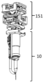
"근위" 또는 "근위 단부"라는 것은, 바늘 팁으로부터 이격하는 또는 대향하는 중공 바늘의 단부, 예를 들어 도 1a 내지 도 1f에 도시된 바와 같이, z-액추에이터(12) 및 지지 기부(11)에 더 근접한 중공 바늘(14)의 단부를 의미한다.By "proximal" or "proximal end" is meant the end of the hollow needle that is spaced apart from or opposite the needle tip, for example the z-
"원위" 또는 "원위 단부"라는 것은 바늘 팁(예를 들어, 도 1a 내지 도 1f의 바늘 팁(18))에 있거나 가까운 중공 바늘의 단부를 의미한다.By “distal” or “distal end” is meant the end of the hollow needle at or near the needle tip (eg,
"공심률(coring rate)"이라는 것은 중공 바늘 작동의 총수로부터 치료 영역으로부터 공심된(cored) 조직 제거를 야기하는 중공 바늘 작동의 퍼센트를 의미한다. 본 발명의 중공 바늘은 공심률을 최대화하고 공심된 조직 제거를 야기하지 않는 중공 바늘 작동을 최소화하도록 설계된다. 조직 부분은 공심력이 조직 저항력을 초과할 때 피부로부터 탈착한다. 조직 저항력은 그 주위 조직으로의 조직 부분의 연결에 의해 결정된다. 예를 들어, 중공 바늘이 피부의 진피층을 통해 완전히 삽입될 때, 피부 저항력은 바늘의 루멘 내의 조직 부분과 피하 지방층 사이의 연결에 의해 결정된다. 공심률은 예를 들어, 중공 바늘의 공심력, 중공 바늘의 루멘벽과 조직 부분 사이의 마찰, 및 조직 저항력에 의해 결정된다. 공심률은 중공 바늘을 가로지르는 압력차를 인가함으로써 또한 영향을 받을 수도 있다. 예를 들어, 중공 바늘의 근위 단부에 인가된 진공은 중공 바늘로부터 공심된 조직 부분을 흡인할 수도 있어, 이에 의해 공심률을 증가시킨다.By "coring rate" is meant the percentage of hollow needle actuations that result in removal of cored tissue from the treatment area from the total number of hollow needle actuations. The hollow needles of the present invention are designed to maximize hollow core rate and minimize hollow needle actuation that does not result in hollow core tissue removal. Tissue parts detach from the skin when the air core force exceeds the tissue resistive force. Tissue resistance is determined by the connection of a tissue portion to the surrounding tissue. For example, when a hollow needle is fully inserted through the dermal layer of skin, skin resistance is determined by the connection between the tissue portion in the lumen of the needle and the subcutaneous fat layer. The hollow core ratio is determined by, for example, the core force of the hollow needle, the friction between the lumen wall of the hollow needle and the tissue portion, and the tissue resistance force. Cavity rate can also be influenced by applying a pressure differential across the hollow needle. For example, a vacuum applied to the proximal end of the hollow needle may suck the hollowed tissue portion out of the hollow needle, thereby increasing the hollow core rate.
"공심력"이라는 것은, 바늘이 피부로부터 후퇴됨에 따라 장치의 중공 바늘에 의해 공심된 조직 부분에 인가된 힘을 의미한다. 공심력은 예를 들어, 바늘이 피부로부터 후퇴될 때의 중공 바늘의 루멘벽과 공심된 조직 부분 사이의 마찰 및 중공 바늘 내의 마이크로 특징부의 위치, 기하학 형상, 및 배향에 의해 결정된다.By "core force" is meant the force applied to the portion of tissue hollowed by the hollow needle of the device as the needle is withdrawn from the skin. The core force is determined by, for example, the position, geometry, and orientation of micro-features within the hollow needle and the friction between the hollow needle's lumen wall and the cored tissue portion as the needle is withdrawn from the skin.
"삽입력"이라는 것은 피부 내에 삽입됨에 따라 중공 바늘에 의해 피부 상에 발생된 힘을 의미한다. 삽입력은 조직을 관통하도록 요구된 힘의 양에 의해 초기에 결정된다. 일단 조직이 관통되면, 삽입력은 바늘벽(내부 및 외부)과 주위 조직 사이의 마찰, 뿐만 아니라 바늘의 팁에서 조직을 분리하는데 요구된 힘에 의해 결정된다.By "insertion force" is meant the force generated on the skin by a hollow needle as it is inserted into the skin. The insertion force is initially determined by the amount of force required to penetrate the tissue. Once tissue is penetrated, the insertion force is determined by the friction between the needle wall (inner and outer) and the surrounding tissue, as well as the force required to separate the tissue from the tip of the needle.
본 발명의 다른 특징 및 장점은 이하의 상세한 설명 및 청구범위로부터 명백할 것이다.Other features and advantages of the present invention will be apparent from the following detailed description and claims.
도 1a, 도 1b 및 도 1c는 본 발명의 바늘 조립체의 3개의 사시도를 도시하고 있는 개략도이다.
도 1d는 본 발명의 바늘 조립체의 단면도를 도시하는 개략도이다.
도 1e 및 도 1f는 본 발명의 바늘 조립체의 개별 구성요소를 도시하고 있는 분해도이다.
도 2는 중공 바늘을 위한 가능한 바늘 프롱 구성을 도시하고 있는 개략도이다.
도 3은 중공 바늘의 프롱의 측면도를 도시하고 있는 개략도이다. 프롱의 경사각(α)은 프롱의 측면(31)과 중공 바늘의 종축(32) 사이의 각도를 칭한다.
도 4는 10도, 20도, 또는 30도의 경사각을 갖는 중공 바늘의 2,000회, 8,000회, 및 10,000회 작동 사이클 후에 바늘 힐 열화를 비교하는 사진을 도시하고 있다.
도 5a, 도 5b 및 도 5c는 프롱의 팁에 날카로운 첨단을 각각 갖는 2개의 프롱을 갖는 중공 바늘, 프롱의 팁에 에지를 각각 갖는 2개의 프롱을 갖는 중공 바늘, 및 편평한 팁을 각각 갖는 2개의 프롱을 갖는 중공 바늘을 각각 도시하고 있는 개략도이다.
도 5d는 프롱의 팁에 에지를 각각 갖는 2개의 프롱을 갖는 스웨이징된(swaged) 중공 바늘을 도시하고 있는 개략도이다.
도 5e는 도 5d에 도시되어 있는 스웨이징된 중공 바늘의 단면도를 도시하고 있는 개략도이다.
도 6a 및 도 6b는 중공 바늘의 팁에 마이크로 특징부를 도시하고 있는 사진이다. 도 6a는 바늘 팁에 난형 구멍으로서 마이크로 특징부를 도시하고 있는 사진이고, 도 6b는 바늘 팁에 직사각형 슬릿으로서 마이크로 특징부를 도시하고 있는 사진이다.
도 6c는 2개의 프롱 및 바늘 팁에 U형 마이크로 특징부를 갖는 중공 바늘을 도시하고 있는 개략도이다.
도 7은 비-수직 각도로 중공 바늘의 내부벽을 교차하고 중공 바늘 내부의 공심된 조직 부분에 의해 인가된 저항력에 영향을 미치는 마이크로 특징부를 도시하고 있는 개략도이다.
도 8의 (a), (b), (c), 및 (d)는 다이아몬드상 탄소(DLC)로 코팅된 중공 바늘이 10,000회 작동 사이클 후에 바늘 힐 열화의 어떠한 징후도 나타내지 않았고, 반면에 미코팅 중공 바늘은 10,000회 작동 사이클 후에 바늘 힐 열화를 나타냈다는 것을 도시하고 있는 사진이다. 도 8의 (a)는 임의의 작동 사이클을 경험하기 전에 DLC-코팅된 바늘의 사진이고; 도 8의 (b)는 5,000회 작동 사이클을 경험한 후에 DLC-코팅된 바늘의 사진이고, 도 8의 (c)는 10,000회 작동 사이클을 경험한 후에 DLC-코팅된 바늘의 사진이고, 도 8의 (d)는 10,000회 작동 사이클을 경험한 후에 미코팅 바늘의 사진이다.
도 9는 중공 바늘의 루멘 내부의 공심된 조직 부분 상의 바늘 공심력 및 조직 저항력을 도시하고 있는 개략도이다.
도 10은 중공 바늘의 루멘으로부터 공심된 조직 부분(들)을 제거하는데 사용된 피스톤의 둥근 연마된 단부의 사진이다.
도 11은 그 루멘 내부의 공심된 조직 부분을 포함하는 중공 바늘의 팁에 근접한 흡인 튜브를 도시하고 있는 개략도이다.
도 12는 바늘 팁으로부터 배출된 공심된 조직 부분을 도시하고 있는 사진이다.
도 13은 고압 파열을 인가함으로써 중공 바늘의 근위 단부로부터 공심된 조직 부분을 흡인하는데 사용된 고압 포트를 도시하고 있는 개략도이다. 고압 포트는 흡인된 공심된 조직 부분을 포획하는데 사용된 조직 회수 포트에 커플링된다.
도 14a 및 도 14b는 장치의 커버의 단부에 각각 커플링된 2개의 상이한 스페이서를 도시하고 있는 개략도이다. 도 14a는 중공 바늘의 10 mm 신장을 허용하는 "제로" 스페이서를 도시하고 있고, 도 14b는 중공 바늘의 8 mm 신장을 허용하는 "2 mm" 스페이서를 도시하고 있다. 도시되어 있는 신장 길이는 단지 예시적인 것이고, 한정이 되도록 의도된 것은 아니다.
도 15a는 x- 및 y-액추에이터를 포함하는 작동 유닛을 도시하고 있는 사진이다.
도 15b는 작동 유닛에 연결된 본 발명의 바늘 조립체를 도시하고 있는 사진이다.
도 16a는 본 발명의 바늘 조립체 및 작동 유닛을 봉입하는데 사용된 커버를 도시하고 있는 사진이다.
도 16b 및 도 16c는 바늘 조립체 및 작동 유닛이 도 16a에 도시되어 있는 커버에 의해 봉입되기 전(도 16b) 및 후(도 16c)에 작동 유닛에 연결된 본 발명의 바늘 조립체를 도시하고 있는 사진이다.
도 16d, 도 16e 및 도 16f는 바늘 조립체 및 작동 유닛을 봉입하는 커버를 포함하는 본 발명의 장치의 3개의 사시도를 도시하고 있는 개략도이다.
도 16g, 도 16h 및 도 16i는 바늘 조립체 및 작동 유닛을 봉입하는 커버를 포함하는 본 발명의 장치의 3개의 단면도를 도시하고 있는 개략도이다.
도 16j, 도 16k, 도 16l, 도 16m, 도 16n, 도 16o, 도 16p, 및 도 16q는 바늘 조립체 및 작동 유닛을 포함하는 본 발명의 장치의 내부의 8개의 도면을 도시하고 있는 개략도이다.
도 16r, 도 16s, 도 16t, 및 도 16u는 탈착되어 있는 바늘 조립체 및 작동 유닛을 포함하는 본 발명의 장치의 내부의 4개의 도면을 도시하고 있는 분해도이다.
도 17a, 도 17b, 도 17c, 및 도 17d는 부분(171, 172)을 갖는 자기 래치의 4개의 도면을 도시하고 있는 개략도이다.
도 17e 및 도 17f는 부분(171, 172)을 갖는 자기 래치의 2개의 단면도를 도시하고 있는 개략도이다.
도 17g는 자기 래치의 부분(171)을 도시하고 있는 개략도이다.
도 17h 및 도 17i는 자기 래치의 부분(172)을 도시하고 있는 개략도이다.
도 18a, 도 18b, 및 도 18c는 부분(181, 182)을 갖는 압박 클램프의 3개의 도면을 도시하고 있는 개략도이다.
도 19a, 도 19b, 및 도 19c는 부분(191, 192)을 갖는 슬라이딩 클램프의 3개의 도면을 도시하고 있는 개략도이다.
도 20a, 도 20b, 및 도 20c는 부분(201, 202)을 갖는 회전 잠금 장치의 3개의 도면을 도시하고 있는 개략도이다.
도 20d 및 도 20e는 부분(201, 202)을 갖는 회전 잠금 장치의 2개의 단면도를 도시하고 있는 개략도이다.
도 21a, 도 21b, 도 21c, 및 도 21d는 부분(211, 212)을 갖는 걸쇠 래치의 4개의 도면을 도시하고 있는 개략도이다.
도 22a, 도 22b, 도 22c, 및 도 22d는 부분(221, 222)을 갖는 슬라이딩-회전 잠금 장치의 4개의 도면을 도시하고 있는 개략도이다.1A, 1B and 1C are schematic views showing three perspective views of the needle assembly of the present invention.
1D is a schematic diagram showing a cross-sectional view of a needle assembly of the present invention.
1E and 1F are exploded views showing the individual components of the needle assembly of the present invention.
Figure 2 is a schematic diagram showing a possible needle prong configuration for a hollow needle.
3 is a schematic diagram showing a side view of the prongs of a hollow needle. The inclination angle α of the prong refers to the angle between the
FIG. 4 shows photographs comparing needle heel degradation after 2,000, 8,000, and 10,000 actuation cycles of hollow needles with rake angles of 10 degrees, 20 degrees, or 30 degrees.
5A, 5B, and 5C show a hollow needle with two prongs, each with a sharp tip at the tip of the prong, a hollow needle with two prongs, each with an edge at the tip of the prong, and two needles each with a flat tip. It is a schematic diagram each showing a hollow needle with a prong.
5D is a schematic diagram showing a swaged hollow needle with two prongs, each with an edge at the tip of the prong.
FIG. 5E is a schematic diagram showing a cross-sectional view of the swaged hollow needle shown in FIG. 5D.
6A and 6B are photographs showing micro-features on the tip of a hollow needle. FIG. 6A is a photograph showing the micro-feature as an oval hole in the needle tip, and FIG. 6B is a photograph showing the micro-feature as a rectangular slit in the needle tip.
6C is a schematic diagram showing a hollow needle with two prongs and a U-shaped micro-feature in the needle tip.
7 is a schematic diagram showing micro-features that intersect the inner wall of the hollow needle at non-perpendicular angles and affect the resistive force applied by the cored tissue portion inside the hollow needle.
8(a), (b), (c), and (d) show that hollow needles coated with diamond-like carbon (DLC) did not show any sign of needle heel degradation after 10,000 actuation cycles, whereas A photograph showing that the coated hollow needle exhibited needle heel degradation after 10,000 operating cycles. Figure 8(a) is a photograph of a DLC-coated needle before undergoing any actuation cycle; Figure 8(b) is a photograph of the DLC-coated needle after experiencing 5,000 actuation cycles, and Figure 8(c) is a photograph of the DLC-coated needle after experiencing 10,000 actuation cycles; (d) is a photograph of an uncoated needle after experiencing 10,000 actuation cycles.
Figure 9 is a schematic diagram showing the needle core force and tissue resistance force on the cored tissue portion inside the lumen of the hollow needle.
10 is a photograph of the rounded polished end of a piston used to remove hollowed tissue portion(s) from the lumen of a hollow needle.
11 is a schematic diagram showing the aspiration tube proximal to the tip of a hollow needle containing a hollowed tissue portion inside its lumen.
FIG. 12 is a photograph showing a portion of hollowed tissue expelled from the needle tip.
13 is a schematic diagram showing a high pressure port used to aspirate a hollowed out tissue portion from the proximal end of a hollow needle by applying a high pressure burst. The high pressure port is coupled to the tissue retrieval port used to capture the aspirated cavityd tissue portion.
14a and 14b are schematic diagrams showing two different spacers each coupled to the end of the cover of the device. FIG. 14A shows a "zero" spacer allowing 10 mm extension of the hollow needle, and FIG. 14B shows a "2 mm" spacer allowing 8 mm extension of the hollow needle. The stretch lengths shown are illustrative only and are not intended to be limiting.
Figure 15a is a photograph showing an operating unit comprising x- and y-actuators.
15B is a photograph showing the needle assembly of the present invention coupled to an actuation unit.
16A is a photograph showing a cover used to enclose the needle assembly and operation unit of the present invention.
16B and 16C are photographs showing the needle assembly of the present invention connected to the effector unit before (FIG. 16B) and after (FIG. 16C) the needle assembly and effector unit are encapsulated by the cover shown in FIG. 16A. .
Figures 16d, 16e and 16f are schematic views showing three perspective views of the device of the present invention comprising a needle assembly and a cover enclosing an actuation unit.
Figures 16g, 16h and 16i are schematic views showing three cross-sectional views of the device of the present invention comprising a needle assembly and a cover enclosing an actuation unit.
16J, 16K, 16L, 16M, 16N, 16O, 16P, and 16Q are schematic diagrams showing eight views of the interior of a device of the present invention including a needle assembly and an actuation unit.
Figures 16r, 16s, 16t, and 16u are exploded views showing four views of the interior of the device of the present invention, including a detached needle assembly and actuation unit.
17A, 17B, 17C, and 17D are schematic diagrams showing four views of a magnetic
17E and 17F are schematic diagrams showing two cross-sectional views of a magnetic
17G is a schematic diagram showing a
17H and 17I are schematic diagrams showing a
Figures 18a, 18b and 18c are schematic diagrams showing three views of a compression clamp with
19a , 19b and 19c are schematic diagrams showing three views of a sliding clamp with
20a , 20b and 20c are schematic diagrams showing three views of a rotation lock with
20d and 20e are schematic diagrams showing two cross-sectional views of a rotation lock with
21A , 21B , 21C , and 21D are schematic diagrams showing four views of a latch
Figures 22a, 22b, 22c and 22d are schematic diagrams showing four views of a slide-turn lock with
본 발명은 피부로부터 조직 부분을 제거함으로써 피부에 미용 효과를 발생하기 위한(예를 들어, 조직 체적을 제거하고, 피부를 타이트닝하고, 그리고/또는 피부 이완을 감소시킴) 중공 바늘, 바늘 조립체, 작동 유닛, 장치, 키트, 및 방법에 관한 것이다. 이론에 의해 구속되지 않고, 이 접근법은 피부 조직을 감량(debulking)함으로써 그리고 조직 리설페이싱 및 리모델링에 기여하는 생물학적 응답을 트리거링함으로써 피부 리모델링을 용이하게 한다. 특히, 본 발명은 피부 내로 삽입 및 피부로부터 후퇴 후에 중공 바늘의 루멘 내부에 조직 부분을 포획하고 보유함으로써 조직 부분을 공심하는 것이 가능한 중공 바늘, 뿐만 아니라 관련 바늘 조립체, 장치, 키트, 및 방법에 관한 것이다. 공심된 조직 부분은 중공 바늘의 루멘으로부터 제거되고 폐기될 수 있다. 프로세스 특히 피부의 원하는 영역 위에 있고 환자의 신체의 선택된 부위에 위치된 다수의 공심된 피부 조직 부분을 발생하도록 반복될 수 있다. 본 명세서에 설명된 중공 바늘, 바늘 조립체, 작동 유닛, 장치, 키트, 및 방법은 조직 복원을 원하는 환자에 편의성, 수용성, 및 접근성을 유지하면서 현재 이용 가능한 장치 및 기술에 비해 증가된 효용성을 제공한다.The present invention relates to a hollow needle, needle assembly, actuation for producing a cosmetic effect on the skin by removing a tissue portion from the skin (e.g., removing tissue volume, tightening the skin, and/or reducing skin laxity). It relates to units, devices, kits, and methods. Without being bound by theory, this approach facilitates skin remodeling by debulking skin tissue and triggering biological responses that contribute to tissue resulfaging and remodeling. In particular, the present invention relates to a hollow needle capable of hollow core of a tissue portion by capturing and retaining the tissue portion inside the lumen of the hollow needle after insertion into and withdrawal from the skin, as well as related needle assemblies, devices, kits, and methods. will be. The cored tissue portion may be removed from the lumen of the hollow needle and discarded. The process may be repeated to generate multiple hollowed-out skin tissue portions, particularly over desired areas of skin and located at selected areas of the patient's body. The hollow needles, needle assemblies, actuation units, devices, kits, and methods described herein provide increased utility over currently available devices and technologies while maintaining convenience, acceptability, and accessibility to patients seeking tissue repair. .
바늘needle
본 발명의 장치는 적어도 제1 프롱을 갖는 적어도 하나의 중공 바늘을 포함한다. 몇몇 실시예에서, 프롱의 측면과 중공 바늘의 종축 사이의 각도(예를 들어, 경사각(α))는 적어도 약 20도이다(예를 들어, 경사각(α)은 약 20도 초과, 예로서 약 20도, 22도, 24도, 26도, 28도, 30도, 32도, 34도, 36도, 38도, 및 40도 초과, 또는 약 20도 내지 약 40도, 20도 내지 40도, 20도 내지 38도, 20도 내지 36도, 20도 내지 34도, 20도 내지 32도, 20도 내지 30도, 20도 내지 28도, 20도 내지 26도, 20도 내지 24도, 20도 내지 22도, 22도 내지 40도, 24도 내지 40도, 26도 내지 40도, 28도 내지 40도, 30도 내지 40도, 32도 내지 40도, 34도 내지 40도, 36도 내지 40도, 및 38도 내지 40도의 각도일 수도 있음). 특히, 프롱의 측면과 중공 바늘의 종축 사이의 각도(예를 들어, 경사각(α))는 약 30도이다.The device of the present invention includes at least one hollow needle having at least a first prong. In some embodiments, the angle between the lateral surface of the prong and the longitudinal axis of the hollow needle (eg, inclination angle α) is at least about 20 degrees (eg, inclination angle α is greater than about 20 degrees, such as about greater than 20 degrees, 22 degrees, 24 degrees, 26 degrees, 28 degrees, 30 degrees, 32 degrees, 34 degrees, 36 degrees, 38 degrees, and 40 degrees, or about 20 degrees to about 40 degrees, 20 degrees to 40 degrees; 20 degrees to 38 degrees, 20 degrees to 36 degrees, 20 degrees to 34 degrees, 20 degrees to 32 degrees, 20 degrees to 30 degrees, 20 degrees to 28 degrees, 20 degrees to 26 degrees, 20 degrees to 24 degrees, 20 degrees to 22 degrees, 22 degrees to 40 degrees, 24 degrees to 40 degrees, 26 degrees to 40 degrees, 28 degrees to 40 degrees, 30 degrees to 40 degrees, 32 degrees to 40 degrees, 34 degrees to 40 degrees, 36 degrees to 40 degrees degrees, and may be at an angle of 38 degrees to 40 degrees). In particular, the angle between the side surface of the prong and the longitudinal axis of the hollow needle (eg, inclination angle α) is about 30 degrees.
몇몇 실시예에서, 중공 바늘의 프롱의 팁은 에지이다. 몇몇 실시예에서, 중공 바늘의 프롱의 팁은 적어도 2개의 차원을 갖는 편평한 팁이다. 몇몇 실시예에서, 중공 바늘의 프롱은 팁 마이크로 특징부를 포함한다. 본 발명의 중공 바늘은 바늘 팁 말림 및 마모(예를 들어, 무뎌짐), 바늘 힐 열화, 및 바늘 굽힘과 같은, 사용 중의 빈번한 바늘 손상을 방지하도록 구성된다. 본 발명의 중공 바늘은 다수회의 작동 사이클(예를 들어, 1,000회, 2,000회, 3,000회, 4,000회, 5,000회, 6,000회, 7,000회, 8,000회, 9,000회, 10,000회, 11,000회, 12,000회, 13,000회, 14,000회, 15,000회, 또는 20,000회 초과의 작동 사이클)에 걸쳐 기계적 무결성 및 내구성을 유지하도록 설계된다. 바람직하게는, 이들 바늘은 또한 높은 공심률을 갖는 피부로부터 조직 부분을 효과적으로 제거한다. 피부 조직 내에 미용 효과를 생성하기 위해, 장치의 중공 바늘은, 바람직하게는 미리결정된 힘을 사용하여 미리결정된 깊이로 피부 조직 내로 삽입되어, 중공 바늘이 중공 바늘의 루멘 내에 피부 조직의 부분을 포획함으로써 피부 조직의 부분을 제거하게 된다.In some embodiments, the tip of the prong of the hollow needle is an edge. In some embodiments, the tip of the prong of the hollow needle is a flat tip with at least two dimensions. In some embodiments, the prongs of the hollow needle include tip micro features. The hollow needle of the present invention is configured to prevent frequent needle damage during use, such as needle tip curling and abrasion (eg, blunting), needle heel deterioration, and needle bending. The hollow needle of the present invention can be subjected to multiple actuation cycles (e.g., 1,000, 2,000, 3,000, 4,000, 5,000, 6,000, 7,000, 8,000, 9,000, 10,000, 11,000, 12,000 , 13,000, 14,000, 15,000, or greater than 20,000 operating cycles) are designed to maintain mechanical integrity and durability. Preferably, these needles also effectively remove tissue portions from the skin that have a high porosity. To create a cosmetic effect within the skin tissue, the hollow needle of the device is inserted into the skin tissue to a predetermined depth, preferably using a predetermined force, such that the hollow needle captures a portion of the skin tissue within the lumen of the hollow needle, thereby A portion of the skin tissue is removed.
프롱Prong
도 2에 도시된 바와 같이, 장치의 중공 바늘의 원위 단부(20)(예를 들어, 피부 조직을 관통하는 바늘의 단부)는 하나 이상의 프롱(21)을 형성하도록 성형될 수 있다. 장치의 중공 바늘은 원위 단부에 하나의 프롱, 2개의 프롱, 또는 2개 초과의 프롱(예를 들어, 3개, 4개, 5개, 또는 6개의 프롱)을 가질 수도 있다. 하나의 프롱을 갖는 중공 바늘이 중공 바늘의 종축에 대해 소정 각도로 중공 바늘의 원위 단부의 일 측면을 연삭함으로써 형성될 수도 있다. 2개의 프롱을 갖는 중공 바늘이 중공 바늘의 종축에 대해 소정 각도로 중공 바늘의 원위 단부의 대향 측면을 연삭함으로써 형성될 수도 있다.As shown in FIG. 2 , the
중공 바늘의 원위 단부에서 프롱의 기하학 형상은 경사각에 의해 특징화될 수 있다. 경사각, 예를 들어 도 3에 도시된 바와 같은 각도(α)는 프롱의 측면(31)과 중공 바늘의 종축(32) 사이의 각도를 칭한다. "2α"의 각도는 중공 바늘의 프롱의 2개의 측면 사이의 각도, 예를 들어 중공 바늘의 측면(31)과 측면(33) 사이의 각도를 칭한다. 프롱의 측면과 중공 바늘의 종축 사이의 경사각(α)은 적어도 약 20도일 수도 있다(예를 들어, 약 20도 내지 약 40도(예를 들어, 20도, 22도, 24도, 26도, 28도, 30도, 32도, 34도, 36도, 38도, 또는 40도)). 특히, 프롱의 측면과 중공 바늘의 종축 사이의 각도는 약 30도일 수도 있다. 2개 이상의 프롱을 갖는 중공 바늘(예를 들어, 도 2)에 있어서, 각각의 프롱은 동일한 경사각 또는 상이한 경사각을 가질 수도 있다. 하나의 실시예에서, 2개의 프롱, 예를 들어 제1 프롱 및 제2 프롱을 갖는 중공 바늘에 있어서, 제1 프롱의 측면과 중공 바늘의 종축 사이의 각도는 약 20도 내지 약 30도(예를 들어, 20도, 22도, 24도, 26도, 28도, 또는 30도)일 수도 있고, 제2 프롱의 측면과 중공 바늘의 종축 사이의 각도는 약 30도 내지 약 40도(예를 들어, 30도, 32도, 34도, 36도, 38도, 또는 30도)일 수도 있다. 예를 들어, 제1 프롱은 20도의 경사각(α)을 가질 수도 있고, 제2 프롱은 30도의 경사각(α)을 가질 수도 있다.The geometry of the prongs at the distal end of the hollow needle can be characterized by the inclination angle. The angle of inclination, for example angle α as shown in FIG. 3, refers to the angle between the
적어도 약 20도 이상의 경사각(α)이 피부 조직 내로의 삽입 및 후퇴의 다수회의 작동 사이클에 걸쳐 바늘의 기계적 무결성을 향상시킨다. 이하의 표 1은 40도의 2α 경사각을 갖는 2-프롱 중공 바늘(각각의 프롱의 경사각(α)은 20도임)이 20도의 2α 경사각을 갖는 2-프롱 중공 바늘(각각의 프롱의 경사각(α)은 10도임)에 비해 바늘 팁 말림의 발생을 감소시킨다는 것을 나타내고 있다. 10°의 경사각(α)을 각각 갖는 총 5개의 2-프롱 중공 바늘 및 20°의 경사각(α)을 각각 갖는 5개의 2-프롱 중공 바늘이 시험되었다.An inclination angle (α) of at least about 20 degrees improves the mechanical integrity of the needle over multiple actuation cycles of insertion and retraction into skin tissue. Table 1 below shows a 2-prong hollow needle having a 2α inclination angle of 40 degrees (inclination angle α of each prong is 20 degrees) and a 2-prong hollow needle having a 2α inclination angle of 20 degrees (inclination angle α of each prong) is 10 degrees) to reduce the occurrence of needle tip curling. A total of five 2-prong hollow needles each having a rake angle α of 10° and five 2-prong hollow needles each having a rake angle α of 20° were tested.

부가적으로, 도 4는 프롱의 바늘 경사각(α)을 증가시키는 것이 또한 다수회의 작동 사이클에 걸쳐 바늘 힐 열화의 발생을 감소시킨다는 것을 도시하고 있다. 도 4에 도시된 바와 같이, 10도의 경사각(α)을 갖는 중공 바늘은 2,000회 작동 사이클 전에 바늘 힐 열화의 징후를 나타냈고(점선 원에 의해 지시되어 있음), 반면에 20도의 경사각(α)을 갖는 중공 바늘 및 30도의 경사각(α)을 갖는 중공 바늘은 10,000회 작동 사이클에 걸쳐 바늘 힐 열화의 어떠한 명백한 징후도 나타내지 않았다.Additionally, FIG. 4 shows that increasing the needle inclination angle α of the prongs also reduces the occurrence of needle heel degradation over multiple actuation cycles. As shown in Fig. 4, the hollow needle with an inclination angle (α) of 10 degrees showed signs of needle heel degradation before 2,000 actuation cycles (indicated by the dashed circle), whereas the inclination angle (α) of 20 degrees The hollow needles with a r and a rake angle (α) of 30 degrees did not show any obvious signs of needle heel deterioration over 10,000 actuation cycles.
중공 바늘의 프롱의 팁은 다양한 기하학 형상을 가질 수도 있다. 예를 들어, 프롱의 팁은 날카로운 첨단(예를 들어, 도 5a에 도시된 바와 같은 날카로운 첨단(51)) 또는 에지(예를 들어, 1차원 에지)(예를 들어, 도 5b에 도시된 바와 같은 에지(52))를 가질 수도 있다. 팁에 에지를 갖는 프롱에 있어서, 프롱의 각각의 경사각은 적어도 약 20도(예를 들어, 약 20도 내지 약 40도(예를 들어, 약 30도))일 수도 있다. 2개 이상의 프롱, 예를 들어 2개의 프롱을 갖는 중공 바늘에 있어서, 프롱은 상이한 경사각(예를 들어, 제1 프롱에서 약 20도의 경사각(α) 및 제2 프롱에서 약 30도의 경사각(α))을 가질 수도 있다. 프롱의 팁은 편평한 팁(예를 들어, 2개의 차원을 갖는 편평한 팁)(예를 들어, 도 5c에 도시된 바와 같은 편평한 팁(53))일 수도 있다. 예를 들어, 편평한 팁은 길이 및 폭을 갖는다. 프롱의 편평한 팁의 표면(길이/폭)은 중공 바늘의 종축에 대해 소정 각도로 있을 수도 있다. 예를 들어, 편평한 팁의 표면은 중공 바늘의 종축에 수직일 수도 있고(예를 들어, 중공 바늘의 종축에 대해 90도 각도에 있음) 또는 편평한 팁의 표면은 중공 바늘의 종축에 대해 비-90도 각도(예를 들어, 약 3 내지 약 89도, 예로서 3 내지 89도, 예를 들어, 3도, 6도, 9도, 12도, 15도, 18도, 21도, 24도, 27도, 30도, 33도, 36도, 39도, 42도, 45도, 48도, 51도, 54도, 57도, 60도, 63도, 66도, 69도, 72도, 75도, 78도, 81도, 84도, 87도, 및 89도)에 있을 수도 있다. 편평한 팁의 표면은 수평일 수도 있고 또는 상이한 기하학 형상, 예를 들어, 원호, 홈을 갖거나, 또는 비-수평일 수도 있다. 2차원 편평한 팁을 갖는 프롱에 있어서, 프롱의 각각의 경사각은 약 2도 내지 약 40도(예를 들어, 2도, 4도, 6도, 8도, 10도, 12도, 14도, 16도, 18도, 20도, 22도, 24도, 26도, 28도, 30도, 32도, 34도, 36도, 38도, 또는 40도)일 수도 있다. 바늘은 프롱 중 하나 또는 양자 모두가 적어도 약 20도(예를 들어, 약 20도 내지 약 40도(예를 들어, 약 30도))의 경사각(α)을 갖는 2차원 편평한 팁을 각각 갖는 하나 또는 2개의 프롱을 가질 수도 있다. 1차원 에지 또는 2차원 편평한 팁을 갖는 바늘은 바늘 팁 말림의 감소된 가능도를 나타낸다.The tip of the prong of the hollow needle may have a variety of geometries. For example, the tip of the prong may be a sharp point (eg,
게이지, gauge, 내경inner diameter , 및 길이, and length
본 발명의 장치의 중공 바늘은 18 내지 30의 게이지(예를 들어, 18, 19, 20, 21, 22, 23, 24, 25, 26, 27, 28, 29, 및 30 게이지)를 포함하는 임의의 게이지를 가질 수도 있다. 중공 바늘의 게이지는 22 내지 25(예를 들어, 22, 23, 24, 및 25 게이지)일 수도 있다. 장치의 중공 바늘은 약 0.14 mm 내지 약 0.84 mm(예를 들어, 0.14, 0.15, 0.16, 0.17, 0.18, 0.19, 0.2, 0.21, 0.22, 0.23, 0.24, 0.25, 0.26, 0.27, 0.28, 0.29, 0.3, 0.31, 0.32, 0.33, 0.34, 0.35, 0.36, 0.37, 0.38, 0.39, 0.4, 0.41, 0.42, 0.43, 0.44, 0.45, 0.46, 0.47, 0.48, 0.49, 0.5, 0.51, 0.52, 0.53, 0.54, 0.55, 0.56, 0.57, 0.58, 0.59, 0.6, 0.61, 0.62, 0.63, 0.64, 0.65, 0.66, 0.67, 0.68, 0.69, 0.7, 0.71, 0.72, 0.73, 0.74, 0.75, 0.76, 0.77, 0.78, 0.79, 0.8, 0.81, 0.82, 0.83, 및 0.84 mm)의 내경을 가질 수도 있다. 중공 바늘의 내경은 중공 바늘의 내부 루멘의 직경을 칭한다. 중공 바늘의 내경은 약 0.24 mm 내지 약 0.40 mm(예를 들어, 0.24, 0.25, 0.26, 0.27, 0.28, 0.29, 0.3, 0.31, 0.32, 0.33, 0.34, 0.35, 0.36, 0.37, 0.38, 0.39, 및 0.4 mm)일 수도 있다. 이에 따라, 장치의 중공 바늘에 의해 제거된 피부 조직의 부분(예를 들어, 공심된 조직 부분)의 직경은 일반적으로 중공 바늘의 내경에 대응한다.The hollow needle of the device of the present invention can be any of 18 to 30 gauge, including 18, 19, 20, 21, 22, 23, 24, 25, 26, 27, 28, 29, and 30 gauge. may have a gauge of The hollow needle may have a gauge of 22 to 25 (eg, 22, 23, 24, and 25 gauge). The hollow needle of the device may be between about 0.14 mm and about 0.84 mm (e.g., 0.14, 0.15, 0.16, 0.17, 0.18, 0.19, 0.2, 0.21, 0.22, 0.23, 0.24, 0.25, 0.26, 0.27, 0.28, 0.29, 0.3 , 0.31, 0.32, 0.33, 0.34, 0.35, 0.36, 0.37, 0.38, 0.39, 0.4, 0.41, 0.42, 0.43, 0.44, 0.45, 0.46, 0.47, 0.48, 0.49, 0.5, 0 .51, 0.52, 0.53, 0.54, 0.55 , 0.56, 0.57, 0.58, 0.59, 0.6, 0.61, 0.62, 0.63, 0.64, 0.65, 0.66, 0.67, 0.68, 0.69, 0.7, 0.71, 0.72, 0.73, 0.74, 0.75, 0 .76, 0.77, 0.78, 0.79, 0.8 , 0.81, 0.82, 0.83, and 0.84 mm). The inner diameter of a hollow needle refers to the diameter of the inner lumen of the hollow needle. The hollow needle has an inner diameter of about 0.24 mm to about 0.40 mm (e.g., 0.24, 0.25, 0.26, 0.27, 0.28, 0.29, 0.3, 0.31, 0.32, 0.33, 0.34, 0.35, 0.36, 0.37, 0.38, 0.39, and 0.4 mm). Accordingly, the diameter of the portion of skin tissue removed by the hollow needle of the device (eg, the hollowed out tissue portion) generally corresponds to the inside diameter of the hollow needle.
몇몇 실시예에서, 중공 바늘의 외경 및/또는 내경은 그 길이를 가로질러 다양할 수도 있어, 중공 바늘의 하나의 영역의 직경이 동일한 바늘의 다른 영역의 외경 및/또는 내경과는 상이할 수도 있게 된다. 중공 바늘을 가로지르는 직경의 변화는 연속적일 수도 있고 또는 아닐 수도 있다. 중공 바늘은 완전히 원통형일 수도 있고 또는 아닐 수도 있다. 예를 들어, 하나 이상의 중공 바늘은 하나 이상의 차원에서 그리고 이들의 길이의 일부 또는 전체를 따라 직사각형, 톱니형, 가리비형, 및/또는 불규칙형일 수도 있다. 몇몇 실시예에서, 내부 루멘 직경은 중공 바늘의 길이를 따라 다양할 수도 있다. 본 발명은 또한 적어도 20도(예를 들어, 약 20도 내지 약 40도(예를 들어, 20도, 22도, 24도, 26도, 28도, 30도, 32도, 34도, 36도, 38도, 또는 40도))의 경사각(α) 및 그 길이에 걸쳐 가변 내부 루멘 직경을 갖는 스웨이징된 중공 바늘을 특징으로 한다. 도 5d 및 도 5e는 중공 바늘의 원위 단부 부근에(예를 들어, 피부 조직을 관통하는 바늘의 단부 부근에) 더 작은 직경을 갖는 스웨이징된 중공 바늘(54)을 도시하고 있다. 도 5d는 스웨이징된 중공 바늘(54)의 외부를 도시하고 있고, 도 5e는 스웨이징된 중공 바늘(54)의 종방향 단면을 도시하고 있다. 다른 실시예에서, 내경은 중공 바늘의 근위 단부(예를 들어, 피부를 관통하는 팁으로부터 이격해 있는)에서 더 넓을 수도 있다. 이는 중공 바늘로부터 공심된 조직 부분의 제거를 용이하게 할 수도 있고, 중공 바늘의 청소를 위한 요구를 제한할 수도 있고, 바늘 막힘의 발생을 감소시킬 수도 있다.In some embodiments, the outer and/or inner diameter of a hollow needle may vary across its length, such that the diameter of one region of a hollow needle may differ from the outer and/or inner diameter of another region of the same needle. do. The change in diameter across the hollow needle may or may not be continuous. The hollow needle may or may not be perfectly cylindrical. For example, one or more hollow needles may be rectangular, serrated, scalloped, and/or irregular in one or more dimensions and along part or all of their length. In some embodiments, the inner lumen diameter may vary along the length of the hollow needle. The present invention also relates to at least 20 degrees (e.g., from about 20 degrees to about 40 degrees (e.g., 20 degrees, 22 degrees, 24 degrees, 26 degrees, 28 degrees, 30 degrees, 32 degrees, 34 degrees, 36 degrees). , 38 degrees, or 40 degrees) and a swaged hollow needle with a variable inner lumen diameter over its length. 5D and 5E show a swaged
장치의 중공 바늘은 다양한 길이를 가질 수도 있고, 다양한 유효 길이(예를 들어, 피부 조직을 관통하도록 구성된 중공 바늘의 길이)를 가질 수도 있다. 유효 길이는 약 0.5 mm 내지 약 10 mm(예를 들어, 0.5, 0.6, 0.8, 1, 1.2, 1.4, 1.6, 1.8, 2, 2.2, 2.4, 2.6, 2.8, 3, 3.2, 3.4, 3.6, 3.8, 4, 4.2, 4.4, 4.6, 4.8, 5, 5.2, 5.4, 5.6, 5.8, 6, 6.2, 6.4, 6.6, 6.8, 7, 7.2, 7.4, 7.6, 7.8, 8, 8.2, 8.4, 8.6, 8.8, 9, 9.2, 9.4, 9.6, 9.8, 및 10 mm)로 다양할 수도 있고, 수동 또는 자동 제어부(예를 들어, 스크롤 휠 또는 전자기 액추에이터와 같은 작동 기구)로 선택 가능할 수도 있다. 중공 바늘의 유효 길이는 치료를 필요로 하는 피부 영역에 따라 조정되고 선택될 수도 있다. 예를 들어, 약 0.5 mm 내지 약 2 mm(예를 들어, 0.5, 0.6, 0.8, 1, 1.2, 1.4, 1.6, 1.8, 및 2 mm)의 유효 길이를 갖는 중공 바늘이 얇은 피부, 예를 들어 눈꺼풀의 피부를 치료하는데 사용될 수도 있다. 눈꺼풀의 표피층 및 진피층의 두께는 약 0.5 mm 내지 약 1 mm(예를 들어, 0.5, 0.6, 0.8, 및 1)일 수도 있다. 약 5 mm 내지 약 10 mm(예를 들어, 5, 6, 7, 8, 9, 및 10 mm)의 유효 길이를 갖는 중공 바늘은 두꺼운 피부, 예를 들어 건강한 피부 조직보다 더 두꺼울 수도 있는 등 또는 흉터 조직의 피부를 치료하는데 사용될 수도 있다. 피부의 표피층의 두께는 약 0.05 내지 약 2 mm(예를 들어, 0.05 내지 2, 0.05 내지 1.95, 0.05 내지 1.9, 0.05 내지 1.85, 0.05 내지 1.8, 0.05 내지 1.75, 0.05 내지 1.7, 0.05 내지 1.65, 0.05 내지 1.6, 0.05 내지 1.55, 0.05 내지 1.5, 0.05 내지 1.45, 0.05 내지 1.4, 0.05 내지 1.35, 0.05 내지 1.3, 0.05 내지 1.25, 0.05 내지 1.2, 0.05 내지 1.15, 0.05 내지 1.1, 0.05 내지 1.05, 0.05 내지 1, 0.05 내지 0.95, 0.05 내지 0.9, 0.05 내지 0.85, 0.05 내지 0.8, 0.05 내지 0.75, 0.05 내지 0.7, 0.05 내지 0.65, 0.05 내지 0.6, 0.05 내지 0.55, 0.05 내지 0.5, 0.05 내지 0.45, 0.05 내지 0.4, 0.05 내지 0.35, 0.05 내지 0.3, 0.05 내지 0.25, 0.05 내지 0.2, 0.05 내지 0.15, 0.05 내지 0.1, 0.1 내지 2, 0.15 내지 2, 0.2 내지 2, 0.25 내지 2, 0.3 내지 2, 0.35 내지 2, 0.4 내지 2, 0.45 내지 2, 0.5 내지 2, 0.55 내지 2, 0.6 내지 2, 0.65 내지 2, 0.7 내지 2, 0.75 내지 2, 0.8 내지 2, 0.85 내지 2, 0.9 내지 2, 0.95 내지 2, 1 내지 2, 1.05 내지 2, 1.15 내지 2, 1.2 내지 2, 1.25 내지 2, 1.3 내지 2, 1.35 내지 2, 1.4 내지 2, 1.45 내지 2, 1.5 내지 2, 1.55 내지 2, 1.6 내지 2, 1.65 내지 2, 1.7 내지 2, 1.75 내지 2, 1.8 내지 2, 1.85 내지 2, 1.9 내지 2, 및 1.95 내지 2 mm)일 수도 있다. 피부의 진피층의 두께는 2 내지 8 mm(예를 들어, 2 내지 8, 2 내지 7.5, 2 내지 7, 2 내지 6.5, 2 내지 6, 2 내지 5.5, 2 내지 5, 2 내지 4.5, 2 내지 4, 2 내지 3.5, 2 내지 3, 2 내지 2.5, 2.5 내지 8, 3 내지 8, 3.5 내지 8, 4 내지 8, 4.5 내지 8, 5 내지 8, 5.5 내지 8, 6 내지 8, 6.5 내지 8, 7 내지 8, 및 7.5 내지 8 mm)일 수도 있다. 중공 바늘의 유효 길이는 피부의 표피층 및/또는 진피층을 관통하도록 조정되고 선택될 수도 있다.The hollow needle of the device may have various lengths and may have various effective lengths (eg, the length of a hollow needle configured to penetrate skin tissue). The effective length is from about 0.5 mm to about 10 mm (e.g., 0.5, 0.6, 0.8, 1, 1.2, 1.4, 1.6, 1.8, 2, 2.2, 2.4, 2.6, 2.8, 3, 3.2, 3.4, 3.6, 3.8 , 4, 4.2, 4.4, 4.6, 4.8, 5, 5.2, 5.4, 5.6, 5.8, 6, 6.2, 6.4, 6.6, 6.8, 7, 7.2, 7.4, 7.6, 7.8, 8, 8.2, 8.4, 8.6, 8.8 , 9, 9.2, 9.4, 9.6, 9.8, and 10 mm), and may be selectable by manual or automatic control (e.g., an actuating mechanism such as a scroll wheel or electromagnetic actuator). The effective length of the hollow needle may be adjusted and selected according to the skin area in need of treatment. For example, a hollow needle having an effective length of about 0.5 mm to about 2 mm (e.g., 0.5, 0.6, 0.8, 1, 1.2, 1.4, 1.6, 1.8, and 2 mm) may be used in thin skin, e.g. It can also be used to treat the skin of the eyelids. The thickness of the epidermal and dermal layers of the eyelid may be between about 0.5 mm and about 1 mm (eg, 0.5, 0.6, 0.8, and 1). A hollow needle having an effective length of about 5 mm to about 10 mm (eg, 5, 6, 7, 8, 9, and 10 mm) may be thicker than thick skin, eg, healthy skin tissue, etc.; or It can also be used to treat skin of scar tissue. The thickness of the epidermal layer of the skin ranges from about 0.05 to about 2 mm (e.g., 0.05 to 2, 0.05 to 1.95, 0.05 to 1.9, 0.05 to 1.85, 0.05 to 1.8, 0.05 to 1.75, 0.05 to 1.7, 0.05 to 1.65, 0.05 to 1.6, 0.05 to 1.55, 0.05 to 1.5, 0.05 to 1.45, 0.05 to 1.4, 0.05 to 1.35, 0.05 to 1.3, 0.05 to 1.25, 0.05 to 1.2, 0.05 to 1.15, 0.05 to 1.1, 0.05 to 1.05, 0.05 to 1 , 0.05 to 0.95, 0.05 to 0.9, 0.05 to 0.85, 0.05 to 0.8, 0.05 to 0.75, 0.05 to 0.7, 0.05 to 0.65, 0.05 to 0.6, 0.05 to 0.55, 0.05 to 0.5, 0.05 to 0.45, 0.05 to 0.4, 0.05 0.35, 0.05 to 0.3, 0.05 to 0.25, 0.05 to 0.2, 0.05 to 0.15, 0.05 to 0.1, 0.1 to 2, 0.15 to 2, 0.2 to 2, 0.25 to 2, 0.3 to 2, 0.35 to 0.4 to 0.4 to 2 , 0.45 to 2, 0.5 to 2, 0.55 to 2, 0.6 to 2, 0.65 to 2, 0.7 to 2, 0.75 to 2, 0.8 to 2, 0.85 to 2, 0.9 to 2, 0.95 to 2, 1 to 2, 1.05 to 2, 1.15 to 2, 1.2 to 2, 1.25 to 2, 1.3 to 2, 1.35 to 2, 1.4 to 2, 1.45 to 2, 1.5 to 2, 1.55 to 2, 1.6 to 2, 1.65 to 2, 1.7 to 2 , 1.75 to 2, 1.8 to 2, 1.85 to 2, 1.9 to 2, and 1.95 to 2 mm). The thickness of the dermal layer of the skin is 2 to 8 mm (eg, 2 to 8, 2 to 7.5, 2 to 7, 2 to 6.5, 2 to 6, 2 to 5.5, 2 to 5, 2 to 4.5, 2 to 4 , 2 to 3.5, 2 to 3, 2 to 2.5, 2.5 to 8, 3 to 8, 3.5 to 8, 4 to 8, 4.5 to 8, 5 to 8, 5.5 to 8, 6 to 8, 6.5 to 8, 7 to 8, and 7.5 to 8 mm). The effective length of the hollow needle may be adjusted and selected to pierce the epidermal and/or dermal layers of the skin.
중공 바늘의 유효 길이는 본 명세서에서 더 상세히 설명되는 하나 이상의 스페이서(도 14 참조)를 사용하여 또한 조정될 수도 있다. 중공 바늘 파라미터는 피부의 영역 및 치료될 조건에 기초하여 선택될 수도 있다. 예를 들어, 뺨 위의 얇은 이완된 피부의 치료는 약 2 mm의 유효 길이 및 중간 게이지(예를 들어, 25 게이지)를 갖는 중공 바늘로부터 이익을 얻을 수도 있고, 반면에 등 위의 두꺼운 피부의 치료 또는 흉터 조직의 치료는 5 mm에 더 가까운 유효 길이 및 더 두꺼운 게이지(예를 들어, 22 게이지)를 갖는 중공 바늘로부터 이익을 얻을 수도 있다. 장치의 중공 바늘은 피부 조직의 다양한 깊이로 신장하도록 구성될 수도 있다. 중공 바늘의 관통의 깊이는 중공 바늘의 유효 길이(예를 들어, 약 2 mm 내지 약 5 mm)에 의해 결정될 수도 있다. 중공 바늘은 (i) 진피층 내로, (ii) 전체 진피층을 통해 진피층과 피하 지방층의 경계로, 그리고/또는 (iii) 피하 지방층 내로 신장하도록 구성될 수도 있다.The effective length of the hollow needle may also be adjusted using one or more spacers (see FIG. 14) described in more detail herein. Hollow needle parameters may be selected based on the area of skin and condition to be treated. For example, treatment of thin flaccid skin over the cheeks may benefit from a hollow needle with an effective length of about 2 mm and medium gauge (eg, 25 gauge), whereas the treatment of thick skin over the back may benefit. Treatment or treatment of scar tissue may benefit from a hollow needle having an effective length closer to 5 mm and a thicker gauge (eg, 22 gauge). The device's hollow needle may be configured to extend to various depths of skin tissue. The depth of penetration of the hollow needle may be determined by the effective length of the hollow needle (eg, about 2 mm to about 5 mm). The hollow needle may be configured to extend (i) into the dermal layer, (ii) through the entire dermal layer to the border between the dermal layer and subcutaneous fat layer, and/or (iii) into the subcutaneous fat layer.
마이크로 특징부micro features
장치의 중공 바늘은 하나 이상의 마이크로 특징부를 포함할 수도 있다. 마이크로 특징부는 중공 바늘이 제거될 조직 부분을 포획하거나 "파지"하는 것을 돕는 기능을 하는 중공 바늘의 요소이다. 마이크로 특징부는 중공 바늘의 공심률을 증가시킬 수도 있다. 마이크로 특징부는 중공 바늘의 유효 길이를 따라 임의의 장소에 위치될 수도 있다. 도 6a 및 도 6b에 도시된 바와 같이, 마이크로 특징부(61 또는 62)는 중공 바늘의 팁 부근에 위치된다(예를 들어, 팁 마이크로 특징부). 예를 들어, 팁 마이크로 특징부는 중공 바늘의 프롱(21)의 팁 부근에 위치될 수도 있다. 몇몇 실시예에서, 중공 바늘의 프롱의 팁과 마이크로 특징부의 시작부 사이의 거리는 약 100 ㎛ 내지 약 5 mm(예를 들어, 100 ㎛ 내지 5 mm, 200 ㎛ 내지 5 mm, 300 ㎛ 내지 5 mm, 400 ㎛ 내지 5 mm, 500 ㎛ 내지 5 mm, 600 ㎛ 내지 5 mm, 700 ㎛ 내지 5 mm, 800 ㎛ 내지 5 mm, 900 ㎛ 내지 5 mm, 1 mm 내지 5 mm, 1.1 mm 내지 5 mm, 1.2 mm 내지 5 mm, 1.3 mm 내지 5 mm, 1.4 mm 내지 5 mm, 1.5 mm 내지 5 mm, 1.6 mm 내지 5 mm, 1.7 mm 내지 5 mm, 1.8 mm 내지 5 mm, 1.9 mm 내지 5 mm, 2 mm 내지 5 mm, 2.1 mm 내지 5 mm, 2.2 mm 내지 5 mm, 2.3 mm 내지 5 mm, 2.4 mm 내지 5 mm, 2.5 mm 내지 5 mm, 2.6 mm 내지 5 mm, 2.7 mm 내지 5 mm, 2.8 mm 내지 5 mm, 2.9 mm 내지 5 mm, 3 mm 내지 5 mm, 3.1 mm 내지 5 mm, 3.2 mm 내지 5 mm, 3.3 mm 내지 5 mm, 3.4 mm 내지 5 mm, 3.5 mm 내지 5 mm, 3.6 mm 내지 5 mm, 3.7 mm 내지 5 mm, 3.8 mm 내지 5 mm, 3.9 mm 내지 5 mm, 4 mm 내지 5 mm, 4.1 mm 내지 5 mm, 4.2 mm 내지 5 mm, 4.3 mm 내지 5 mm, 4.4 mm 내지 5 mm, 4.5 mm 내지 5 mm, 4.6 mm 내지 5 mm, 4.7 mm 내지 5 mm, 4.8 mm 내지 5 mm, 4.9 mm 내지 5 mm, 100 ㎛ 내지 4.9 mm, 100 ㎛ 내지 4.8 mm, 100 ㎛ 내지 4.7 mm, 100 ㎛ 내지 4.6 mm, 100 ㎛ 내지 4.5 mm, 100 ㎛ 내지 4.4 mm, 100 ㎛ 내지 4.3 mm, 100 ㎛ 내지 4.2 mm, 100 ㎛ 내지 4.1 mm, 100 ㎛ 내지 4 mm, 100 ㎛ 내지 3.9 mm, 100 ㎛ 내지 3.8 mm, 100 ㎛ 내지 3.7 mm, 100 ㎛ 내지 3.6 mm, 100 ㎛ 내지 3.5 mm, 100 ㎛ 내지 3.4 mm, 100 ㎛ 내지 3.3 mm, 100 ㎛ 내지 3.2 mm, 100 ㎛ 내지 3.1 mm, 100 ㎛ 내지 3 mm, 100 ㎛ 내지 2.9 mm, 100 ㎛ 내지 2.8 mm, 100 ㎛ 내지 2.7 mm, 100 ㎛ 내지 2.6 mm, 100 ㎛ 내지 2.5 mm, 100 ㎛ 내지 2.4 mm, 100 ㎛ 내지 2.3 mm, 100 ㎛ 내지 2.2 mm, 100 ㎛ 내지 2.1 mm, 100 ㎛ 내지 2 mm, 100 ㎛ 내지 1.9 mm, 100 ㎛ 내지 5 mm, 100 ㎛ 내지 1.8 mm, 100 ㎛ 내지 1.7 mm, 100 ㎛ 내지 1.6 mm, 100 ㎛ 내지 1.5 mm, 100 ㎛ 내지 1.4 mm, 100 ㎛ 내지 1.3 mm, 100 ㎛ 내지 1.2 mm, 100 ㎛ 내지 1.1 mm, 100 ㎛ 내지 1 mm, 100 ㎛ 내지 900 ㎛, 100 ㎛ 내지 800 ㎛, 100 ㎛ 내지 700 ㎛, 100 ㎛ 내지 600 ㎛, 100 ㎛ 내지 500 ㎛, 100 ㎛ 내지 400 ㎛, 100 ㎛ 내지 300 ㎛, 및 100 ㎛ 내지 200 ㎛)이다.The hollow needle of the device may include one or more micro features. Micro-features are elements of the hollow needle that function to help the hollow needle capture or "grip" the portion of tissue to be removed. The micro-features may increase the hollowness of the hollow needle. The micro-features may be located anywhere along the effective length of the hollow needle. As shown in FIGS. 6A and 6B , a micro-feature 61 or 62 is located near the tip of the hollow needle (eg, a tip micro-feature). For example, the tip micro-feature may be located near the tip of the
마이크로 특징부는 다양한 기하학 형상을 가질 수도 있다. 마이크로 특징부는 구멍(도 6a의 구멍(61) 참조)(예를 들어, 원형 구멍 또는 난형 구멍) 또는 슬릿(도 6b의 슬릿(62) 참조)일 수도 있다. 슬릿은 직사각형 슬릿, 정사각형 슬릿, U형 슬릿, 또는 T형 슬릿일 수도 있다. 마이크로 특징부의 형상 및 치수는 중공 바늘의 기계적 강인성 및 무결성에 대한 영향을 최소화하면서, 피부 조직의 부분을 포획하는 중공 바늘의 능력을 최대화하도록 최적화될 수 있다. 몇몇 실시예에서, 마이크로 특징부는 약 10 ㎛ 내지 약 1 mm(예를 들어, 10 ㎛ 내지 1 mm, 10 ㎛ 내지 900 ㎛, 10 ㎛ 내지 880 ㎛, 10 ㎛ 내지 860 ㎛, 10 ㎛ 내지 840 ㎛, 10 ㎛ 내지 820 ㎛, 10 ㎛ 내지 800 ㎛, 10 ㎛ 내지 780 ㎛, 10 ㎛ 내지 760 ㎛, 10 ㎛ 내지 740 ㎛, 10 ㎛ 내지 720 ㎛ 내지, 10 ㎛ 내지 700 ㎛, 10 ㎛ 내지 680 ㎛, 10 ㎛ 내지 660 ㎛, 10 ㎛ 내지 640 ㎛, 10 ㎛ 내지 620 ㎛, 10 ㎛ 내지 600 ㎛, 10 ㎛ 내지 580 ㎛, 10 ㎛ 내지 560 ㎛, 10 ㎛ 내지 540 ㎛, 10 ㎛ 내지 520 ㎛, 10 ㎛ 내지 500 ㎛, 10 ㎛ 내지 480 ㎛, 10 ㎛ 내지 460 ㎛, 10 ㎛ 내지 440 ㎛, 10 ㎛ 내지 420 ㎛, 10 ㎛ 내지 400 ㎛, 10 ㎛ 내지 380 ㎛, 10 ㎛ 내지 360 ㎛, 10 ㎛ 내지 340 ㎛, 10 ㎛ 내지 320 ㎛, 10 ㎛ 내지 300 ㎛, 10 ㎛ 내지 280 ㎛, 10 ㎛ 내지 260 ㎛, 10 ㎛ 내지 240 ㎛, 10 ㎛ 내지 220 ㎛, 10 ㎛ 내지 200 ㎛, 10 ㎛ 내지 180 ㎛, 10 ㎛ 내지 160 ㎛, 10 ㎛ 내지 140 ㎛, 10 ㎛ 내지 120 ㎛, 10 ㎛ 내지 100 ㎛, 10 ㎛ 내지 80 ㎛, 10 ㎛ 내지 60 ㎛, 10 ㎛ 내지 40 ㎛, 10 ㎛ 내지 20 ㎛, 20 ㎛ 내지 1 mm, 40 ㎛ 내지 1 mm, 60 ㎛ 내지 1 mm, 80 ㎛ 내지 1 mm, 100 ㎛ 내지 1 mm, 120 ㎛ 내지 1 mm, 140 ㎛ 내지 1 mm, 160 ㎛ 내지 1 mm, 180 ㎛ 내지 1 mm, 200 ㎛ 내지 1 mm, 220 ㎛ 내지 1 mm, 240 ㎛ 내지 1 mm, 260 ㎛ 내지 1 mm, 280 ㎛ 내지 1 mm, 300 ㎛ 내지 1 mm, 320 ㎛ 내지 1 mm, 340 ㎛ 내지 1 mm, 360 ㎛ 내지 1 mm, 380 ㎛ 내지 1 mm, 400 ㎛ 내지 1 mm, 420 ㎛ 내지 1 mm, 440 ㎛ 내지 1 mm, 460 ㎛ 내지 1 mm, 480 ㎛ 내지 1 mm, 500 ㎛ 내지 1 mm,520 ㎛ 내지 1 mm, 540 ㎛ 내지 1 mm, 560 ㎛ 내지 1 mm, 580 ㎛ 내지 1 mm, 600 ㎛ 내지 1 mm, 620 ㎛ 내지 1 mm, 640 ㎛ 내지 1 mm, 660 ㎛ 내지 1 mm, 680 ㎛ 내지 1 mm, 700 ㎛ 내지 1 mm, 720 ㎛ 내지 1 mm, 740 ㎛ 내지 1 mm, 760 ㎛ 내지 1 mm, 780 ㎛ 내지 1 mm, 800 ㎛ 내지 1 mm, 820 ㎛ 내지 1 mm, 840 ㎛ 내지 1 mm, 860 ㎛ 내지 1 mm, 880 ㎛ 내지 1 mm, 900 ㎛ 내지 1 mm, 920 ㎛ 내지 1 mm, 940 ㎛ 내지 1 mm, 960 ㎛ 내지 1 mm, 및 980 ㎛ 내지 1 mm)의 직경을 갖는 원형 구멍일 수도 있다.The micro-features may have various geometries. The micro-feature may be a hole (see
몇몇 실시예에서, 마이크로 특징부는 길이 및 폭을 갖는 슬릿(예를 들어, 직사각형 슬릿, 정사각형 슬릿, U형 슬릿, 또는 T형 슬릿)일 수도 있고, 여기서 길이 또는 폭은 약 10 ㎛ 내지 약 1 mm (예를 들어, 10 ㎛ 내지 1 mm, 10 ㎛ 내지 900 ㎛, 10 ㎛ 내지 880 ㎛, 10 ㎛ 내지 860 ㎛, 10 ㎛ 내지 840 ㎛, 10 ㎛ 내지 820 ㎛, 10 ㎛ 내지 800 ㎛, 10 ㎛ 내지 780 ㎛, 10 ㎛ 내지 760 ㎛, 10 ㎛ 내지 740 ㎛, 10 ㎛ 내지 720 ㎛, 10 ㎛ 내지 700 ㎛, 10 ㎛ 내지 680 ㎛, 10 ㎛ 내지 660 ㎛, 10 ㎛ 내지 640 ㎛, 10 ㎛ 내지 620 ㎛, 10 ㎛ 내지 600 ㎛, 10 ㎛ 내지 580 ㎛, 10 ㎛ 내지 560 ㎛, 10 ㎛ 내지 540 ㎛, 10 ㎛ 내지 520 ㎛, 10 ㎛ 내지 500 ㎛, 10 ㎛ 내지 480 ㎛, 10 ㎛ 내지 460 ㎛, 10 ㎛ 내지 440 ㎛, 10 ㎛ 내지 420 ㎛, 10 ㎛ 내지 400 ㎛, 10 ㎛ 내지 380 ㎛, 10 ㎛ 내지 360 ㎛, 10 ㎛ 내지 340 ㎛, 10 ㎛ 내지 320 ㎛, 10 ㎛ 내지 300 ㎛, 10 ㎛ 내지 280 ㎛, 10 ㎛ 내지 260 ㎛, 10 ㎛ 내지 240 ㎛, 10 ㎛ 내지 220 ㎛, 10 ㎛ 내지 200 ㎛, 10 ㎛ 내지 180 ㎛, 10 ㎛ 내지 160 ㎛, 10 ㎛ 내지 140 ㎛, 10 ㎛ 내지 120 ㎛, 10 ㎛ 내지 100 ㎛, 10 ㎛ 내지 80 ㎛, 10 ㎛ 내지 60 ㎛, 10 ㎛ 내지 40 ㎛, 10 ㎛ 내지 20 ㎛, 20 ㎛ 내지 1 mm, 40 ㎛ 내지 1 mm, 60 ㎛ 내지 1 mm, 80 ㎛ 내지 1 mm, 100 ㎛ 내지 1 mm, 120 ㎛ 내지 1 mm, 140 ㎛ 내지 1 mm, 160 ㎛ 내지 1 mm, 180 ㎛ 내지 1 mm, 200 ㎛ 내지 1 mm, 220 ㎛ 내지 1 mm, 240 ㎛ 내지 1 mm, 260 ㎛ 내지 1 mm, 280 ㎛ 내지 1 mm, 300 ㎛ 내지 1 mm, 320 ㎛ 내지 1 mm, 340 ㎛ 내지 1 mm, 360 ㎛ 내지 1 mm, 380 ㎛ 내지 1 mm, 400 ㎛ 내지 1 mm, 420 ㎛ 내지 1 mm, 440 ㎛ 내지 1 mm, 460 ㎛ 내지 1 mm, 480 ㎛ 내지 1 mm, 500 ㎛ 내지 1 mm, 520 ㎛ 내지 1 mm, 540 ㎛ 내지 1 mm, 560 ㎛ 내지 1 mm, 580 ㎛ 내지 1 mm, 600 ㎛ 내지 1 mm, 620 ㎛ 내지 1 mm, 640 ㎛ 내지 1 mm, 660 ㎛ 내지 1 mm, 680 ㎛ 내지 1 mm, 700 ㎛ 내지 1 mm, 720 ㎛ 내지 1 mm, 740 ㎛ 내지 1 mm, 760 ㎛ 내지 1 mm, 780 ㎛ 내지 1 mm, 800 ㎛ 내지 1 mm, 820 ㎛ 내지 1 mm, 840 ㎛ 내지 1 mm, 860 ㎛ 내지 1 mm, 880 ㎛ 내지 1 mm, 900 ㎛ 내지 1 mm, 920 ㎛ 내지 1 mm, 940 ㎛ 내지 1 mm, 960 ㎛ 내지 1 mm, 및 980 ㎛ 내지 1 mm)일 수도 있다.In some embodiments, a micro-feature may be a slit having a length and a width (eg, a rectangular slit, a square slit, a U-shaped slit, or a T-shaped slit), where the length or width is between about 10 μm and about 1 mm. (eg, 10 μm to 1 mm, 10 μm to 900 μm, 10 μm to 880 μm, 10 μm to 860 μm, 10 μm to 840 μm, 10 μm to 820 μm, 10 μm to 800 μm, 10 μm to 780 μm, 10 μm to 760 μm, 10 μm to 740 μm, 10 μm to 720 μm, 10 μm to 700 μm, 10 μm to 680 μm, 10 μm to 660 μm, 10 μm to 640 μm, 10 μm to 620 μm , 10 μm to 600 μm, 10 μm to 580 μm, 10 μm to 560 μm, 10 μm to 540 μm, 10 μm to 520 μm, 10 μm to 500 μm, 10 μm to 480 μm, 10 μm to 460 μm, 10 ㎛ to 440 ㎛, 10 ㎛ to 420 ㎛, 10 ㎛ to 400 ㎛, 10 ㎛ to 380 ㎛, 10 ㎛ to 360 ㎛, 10 ㎛ to 340 ㎛, 10 ㎛ to 320 ㎛, 10 ㎛ to 300 ㎛, 10 ㎛ to 280 μm, 10 μm to 260 μm, 10 μm to 240 μm, 10 μm to 220 μm, 10 μm to 200 μm, 10 μm to 180 μm, 10 μm to 160 μm, 10 μm to 140 μm, 10 μm to 120 μm , 10 μm to 100 μm, 10 μm to 80 μm, 10 μm to 60 μm, 10 μm to 40 μm, 10 μm to 20 μm, 20 μm to 1 mm, 40 μm to 1 mm, 60 μm to 1 mm, 80 ㎛ to 1 mm, 100 ㎛ to 1 mm, 120 ㎛ to 1 mm, 140 ㎛ to 1 mm, 160 ㎛ to 1 mm, 180 ㎛ to 1 mm, 200 ㎛ to 1 mm, 220 ㎛ to 1 mm, 240 ㎛ to 1 mm, 260 μm to 1 mm, 280 μm to 1 mm, 300 μm to 1 mm, 320 μm to 1 mm, 340 μm to 1 mm, 360 μm to 1 mm, 380 μm to 1 mm, 400 μm to 1 mm , 420 μm to 1 mm, 440 μm to 1 mm, 460 μm to 1 mm, 480 μm to 1 mm, 500 μm to 1 mm, 520 μm to 1 mm, 540 μm to 1 mm, 560 μm to 1 mm, 580 ㎛ to 1 mm, 600 ㎛ to 1 mm, 620 ㎛ to 1 mm, 640 ㎛ to 1 mm, 660 ㎛ to 1 mm, 680 ㎛ to 1 mm, 700 ㎛ to 1 mm, 720 ㎛ to 1 mm, 740 ㎛ to 1 mm, 760 μm to 1 mm, 780 μm to 1 mm, 800 μm to 1 mm, 820 μm to 1 mm, 840 μm to 1 mm, 860 μm to 1 mm, 880 μm to 1 mm, 900 μm to 1 mm , 920 μm to 1 mm, 940 μm to 1 mm, 960 μm to 1 mm, and 980 μm to 1 mm).
마이크로 특징부는 중공 바늘의 루멘 내부에 포획된 조직 부분에 방향성 효과를 미치도록 설계되고 구성될 수도 있다. 예를 들어, 마이크로 특징부의 형상 및 배향은 중공 바늘의 공심력에 영향을 미칠 수도 있다. 도 6c에 도시된 바와 같이, U형 슬릿(63)은 중공 바늘의 팁(21) 부근에 후크를 생성하는데, 이 후크는 피부로부터 바늘의 후퇴시에 중공 바늘의 루멘 내부에 조직 부분을 보유하는 것을 도울 수도 있다. 마이크로 특징부는 날카로운 에지에서 중공 바늘의 내부벽을 교차할 수 있는데, 이는 중공 바늘의 공심력, 뿐만 아니라 중공 바늘의 루멘 내부의 공심된 조직 부분에 의해 인가된 저항력에 방향성 영향을 미칠 수 있다. 중공 바늘 내로 드릴링되거나 마이크로 가공된 마이크로 특징부(예를 들어, 구멍 또는 슬릿)는 직각으로 또는 비-직각으로(예를 들어, 약 5도 내지 약 90도 미만의 각도, 예로서 5 내지 85도, 5 내지 80도, 5 내지 75도, 5 내지 70도, 5 내지 65도, 5 내지 60도, 5 내지 55도, 5 내지 50도, 5 내지 45도, 5 내지 40도, 5 내지 35도, 5 내지 30도, 5 내지 25도, 5 내지 20도, 5 내지 15도, 5 내지 10도, 10 내지 85도, 15 내지 85도, 20 내지 85도, 25 내지 85도, 30 내지 85도, 35 내지 85도, 40 내지 85도, 45 내지 85도, 50 내지 85도, 55 내지 85도, 60 내지 85도, 65 내지 85도, 70 내지 85도, 75 내지 85도, 및 80 내지 85도) 중공 바늘의 내부벽을 교차할 수도 있다. 예를 들어, 도 7은 비-직각(γ)으로 중공 바늘의 내부벽(72)을 교차하고 날카로운 에지(73)를 생성하는 팁 마이크로 특징부(71)를 포함하는 중공 바늘(14)을 도시하고 있다. 조직 부분(74)이 바늘 팁(18)으로부터 중공 바늘에 진입함에 따라, 조직 부분(74)은 더 낮은 저항의 방향으로 진행한다. 중공 바늘(14)이 피부 조직으로부터 후퇴됨에 따라, 뿐만 아니라 일단 중공 바늘(14)이 피부 조직으로부터 해제되면, 마이크로 특징부(71)는 중공 바늘(14)의 루멘 내부에 조직 부분(74)을 보유하는 것을 돕고 조직 부분(74)이 중공 바늘(14)로부터 해제되는 것을 방지한다. 하나 이상의 마이크로 특징부는 레이저 드릴링 및 와이어 정전 방전 가공(EDM)과 같은 이용 가능한 프로세스 및 기술을 통해 중공 바늘 내로 마이크로 가공될 수도 있다.The micro-features may be designed and configured to have a directional effect on the portion of tissue captured inside the lumen of the hollow needle. For example, the shape and orientation of the micro-features may affect the centripetal force of the hollow needle. As shown in FIG. 6C, the U-shaped slit 63 creates a hook near the
바늘 코팅needle coating
장치의 중공 바늘은 중공 바늘의 기계적 무결성, 내구성, 및 신뢰성을 향상시키거나 유지하는 재료(예를 들어, 경질 재료)로 코팅될 수도 있다. 코팅 재료는 피부 조직 내로의 반복된 삽입 및 후퇴 중에 바늘 팁 및 힐의 손상, 마모, 및 마손을 방지하는 것을 도울 수도 있다. 장치의 중공 바늘을 코팅하는데 사용될 수도 있는 재료(예를 들어, 경질 재료)의 예는 TiN, TiCN, TiAlN, ZrN, 및 다이아몬드상 탄소(DLC)를 포함하지만, 이들에 한정되는 것은 아니다. 경질 재료는 중공 바늘의 외부면, 중공 바늘의 내부면(예를 들어, 내부 루멘의 표면), 또는 양 표면에 코팅으로서 도포될 수도 있다. 도 8의 (a) 내지 (c)는 DLC로 코팅된 중공 바늘이 돼지 피부 내로의 삽입 및 후퇴의 10,000회의 작동 사이클에 걸쳐 바늘 힐 및 팁 열화의 감소를 나타내는 것을 도시하고 있고, 반면에 미코팅 중공 바늘은 돼지 피부 내로의 삽입 및 후퇴의 10,000회의 작동 사이클에 걸쳐 바늘 힐 및 팁 열화(점선 원에 의해 지시되어 있음)를 나타낸다(도 8의 (d)).The hollow needle of the device may be coated with a material (eg, a hard material) that enhances or maintains the mechanical integrity, durability, and reliability of the hollow needle. The coating material may help prevent damage, abrasion, and abrasion of the needle tip and heel during repeated insertion and withdrawal into skin tissue. Examples of materials (eg, hard materials) that may be used to coat the hollow needle of the device include, but are not limited to, TiN, TiCN, TiAlN, ZrN, and diamond-like carbon (DLC). The hard material may be applied as a coating to the outer surface of the hollow needle, the inner surface of the hollow needle (eg, the surface of the inner lumen), or both surfaces. 8(a)-(c) show that hollow needles coated with DLC exhibit a reduction in needle heel and tip degradation over 10,000 actuation cycles of insertion and retraction into porcine skin, whereas uncoated The hollow needle shows needle heel and tip degradation (indicated by dotted circles) over 10,000 actuation cycles of insertion and retraction into porcine skin (Fig. 8(d)).
바늘 needle 루멘의of lumen 표면 surface
중공 바늘의 루멘 표면은 중공 바늘의 공심력, 공심률, 및 삽입력에 영향을 미칠 수도 있다. 특히, 루멘 표면과 공심된 조직 부분 사이의 마찰은 공심력, 공심률, 및 삽입력을 결정할 수도 있다. 본 명세서에 설명된 중공 바늘은 공심률을 최대화하고 공심된 조직 제거를 야기하지 않는 중공 바늘 삽입을 최소화하도록 설계된다. 조직 부분은 공심력(예를 들어, 바늘이 피부로부터 후퇴됨에 따라 공심된 조직 부분에 장치의 중공 바늘에 의해 인가된 힘)이 그 주위 조직으로의 조직 부분의 연결에 의해 결정되는 조직 저항력을 초과할 때 피부로부터 탈착된다. 예를 들어, 중공 바늘이 피부의 진피층을 통해 완전히 삽입될 때, 피부 저항력은 바늘의 루멘 내의 조직 부분과 피하 지방층 사이의 연결에 의해 결정된다. 이에 따라, 공심력이 조직 저항력을 초과할 때, 공심된 조직 부분은 중공 바늘의 루멘 내에 포획되고 피부로부터 제거된다(도 9). 거친 루멘 표면은 공심된 조직 부분과 루멘 표면 사이의 마찰을 증가시키는데, 이는 증가된 삽입력, 증가된 공심력, 및 증가된 공심률을 야기할 수도 있다. 루멘 표면의 윤활은 공심된 조직 부분과 루멘 표면 사이의 마찰을 감소시키는데, 이는 감소된 삽입력, 감소된 공심력, 및 감시된 공심률을 야기할 수도 있다. 과도하게 거칠고 불균일한 루멘 표면은 바늘 열화(예를 들어, 바늘 힐 및 팁 열화)의 높은 발생을 유도할 수도 있고, 루멘으로부터 공심된 조직 부분을 제거하는데 있어서 어려움을 유발할 수도 있고, 그리고/또는 바늘 막힘을 유발할 수도 있다. 루멘 표면의 거칠기의 정도는 바늘의 내구성, 삽입력, 바늘 루멘으로부터 조직을 제거하는 능력, 및 열화(예를 들어, 바늘 힐 및 팁 열화)에 대한 바늘의 저항을 손상하지 않고 공심력 및 공심률을 증가시키도록 최적화될 수도 있다.The lumen surface of the hollow needle may affect the hollow needle's hollow needle hollow core force, hollow core rate, and insertion force. In particular, the friction between the lumen surface and the cored tissue portion may determine the core force, core rate, and insertion force. The hollow needles described herein are designed to maximize hollow core rate and minimize hollow needle insertion that does not result in hollow core tissue removal. The tissue portion is such that the core force (e.g., the force applied by the hollow needle of the device to the cored tissue portion as the needle is withdrawn from the skin) exceeds the tissue resistive force determined by the tissue portion's connection to its surrounding tissue. It is released from the skin when For example, when a hollow needle is fully inserted through the dermal layer of skin, skin resistance is determined by the connection between the tissue portion in the lumen of the needle and the subcutaneous fat layer. Accordingly, when the hollow core force exceeds the tissue resistive force, the hollow cored tissue portion is captured in the lumen of the hollow needle and removed from the skin (FIG. 9). A rough lumen surface increases friction between the hollowed tissue portion and the lumen surface, which may result in increased insertion force, increased hollow core force, and increased hollow core ratio. Lubrication of the lumen surface reduces friction between the hollowed tissue portion and the lumen surface, which may result in reduced insertion force, reduced hollow core force, and monitored hollow core ratio. An excessively rough and non-uniform lumen surface may lead to a high incidence of needle degradation (e.g., needle heel and tip degradation), may cause difficulty in removing hollowed out tissue portions from the lumen, and/or needle may cause blockage. The degree of roughness of the surface of the lumen can be adjusted without compromising the needle's durability, insertion force, ability to remove tissue from the needle lumen, and resistance of the needle to degradation (e.g., needle heel and tip degradation). may be optimized to increase
몇몇 실시예에서, 본 발명의 중공 바늘 및 방법은 적어도 약 5%(예를 들어, 약 5% 내지 약 100%, 예로서 5% 내지 100%, 5% 내지 95%, 5% 내지 90%, 5% 내지 85%, 5% 내지 80%, 5% 내지 75%, 5% 내지 70%, 5% 내지 65%, 5% 내지 60%, 5% 내지 55%, 5% 내지 50%, 5% 내지 45%, 5% 내지 40%, 5% 내지 35%, 5% 내지 30%, 5% 내지 25%, 5% 내지 20%, 5% 내지 15%, 5% 내지 10%, 10% 내지 95%, 15% 내지 95%, 20% 내지 95%, 25% 내지 95%, 30% 내지 95%, 35% 내지 95%, 40% 내지 95%, 45% 내지 95%, 50% 내지 95%, 55% 내지 95%, 60% 내지 95%, 65% 내지 95%, 70% 내지 95%, 75% 내지 95%, 80% 내지 95%, 85% 내지 95%, 및 90% 내지 95%)의 공심률을 가질 수도 있다.In some embodiments, the hollow needles and methods of the present invention contain at least about 5% (e.g., about 5% to about 100%, such as 5% to 100%, 5% to 95%, 5% to 90%, 5% to 85%, 5% to 80%, 5% to 75%, 5% to 70%, 5% to 65%, 5% to 60%, 5% to 55%, 5% to 50%, 5% to 45%, 5% to 40%, 5% to 35%, 5% to 30%, 5% to 25%, 5% to 20%, 5% to 15%, 5% to 10%, 10% to 95% %, 15% to 95%, 20% to 95%, 25% to 95%, 30% to 95%, 35% to 95%, 40% to 95%, 45% to 95%, 50% to 95%, 55% to 95%, 60% to 95%, 65% to 95%, 70% to 95%, 75% to 95%, 80% to 95%, 85% to 95%, and 90% to 95%) You may have an empty core rate.
몇몇 실시예에서, 본 발명의 중공 바늘 및 방법은 약 3 N 내지 약 10 N(예를 들어, 3, 3.5, 4, 4.5, 5, 5.5, 6, 6.5, 7, 7.5, 8, 8.5, 9, 9.5, 및 10 N)의 공심력을 가질 수도 있다. 몇몇 실시예에서, 20도의 경사각(α)을 갖는 2-프롱 중공 바늘은 약 3 N 내지 약 10 N(예를 들어, 3, 3.5, 4, 4.5, 5, 5.5, 6, 6.5, 7, 7.5, 8, 8.5, 9, 9.5, 및 10 N)의 공심력을 가질 수도 있다.In some embodiments, the hollow needles and methods of the present invention can withstand about 3 N to about 10 N (e.g., 3, 3.5, 4, 4.5, 5, 5.5, 6, 6.5, 7, 7.5, 8, 8.5, 9 , 9.5, and 10 N). In some embodiments, a 2-prong hollow needle with a rake angle (α) of 20 degrees is about 3 N to about 10 N (e.g., 3, 3.5, 4, 4.5, 5, 5.5, 6, 6.5, 7, 7.5 , 8, 8.5, 9, 9.5, and 10 N).
코팅 재료 및/또는 윤활제는 루멘 표면의 거칠기의 정도, 및 따라서 루멘 표면과 공심된 조직 부분 사이의 마찰에 영향을 미칠 수도 있다. 중공 바늘의 루멘 표면은 중공 바늘을 통해 윤활제 또는 연마 매체를 흘려보냄으로써 연마되어 루멘 표면의 거칠기를 감소시킬 수도 있다. 윤활제의 예는 염-기반 윤활제(예를 들어, 완충 식염수(예를 들어, PBS)), 당-기반 윤활제(예를 들어, 자당 및 포도당 용액), 및 계면활성제-기반 윤활제(예를 들어, Tween20을 함유하는 용액)를 포함하지만, 이들에 한정되는 것은 아니다. 중공 바늘의 루멘 표면의 거칠기의 정도는 중공 바늘을 제조하는데 사용되는 제조 프로세스에 의해 또한 영향을 받을 수도 있다. 이하의 표 2는 단일 플러그, 이중 플러그, 및 함몰 제조(sunk manufacturing) 프로세스를 사용하여 제조된 중공 바늘의 Ra(거칠기 프로파일의 산술 평균) 및 Rz(평균 거칠기 깊이)로 측정된 루멘 표면 거칠기를 나타내고 있다. 이중 플러그 프로세스를 사용하여 제조된 중공 바늘의 루멘 표면은 단일 플러그 프로세스를 사용하여 제조된 중공 바늘의 루멘 표면보다 더 평활하다(더 낮은 Ra 및 Rz 값).The coating material and/or lubricant may affect the degree of roughness of the lumen surface, and thus the friction between the lumen surface and the hollowed-out tissue portion. The lumen surface of the hollow needle may be polished by flowing a lubricant or abrasive medium through the hollow needle to reduce the roughness of the lumen surface. Examples of lubricants are salt-based lubricants (eg, buffered saline (eg, PBS)), sugar-based lubricants (eg, sucrose and glucose solutions), and surfactant-based lubricants (eg, solutions containing Tween20), but are not limited thereto. The degree of roughness of the surface of the lumen of the hollow needle may also be influenced by the manufacturing process used to manufacture the hollow needle. Table 2 below shows the lumen surface roughness measured as Ra (arithmetic average of roughness profiles) and Rz (average roughness depth) of hollow needles manufactured using single plug, double plug, and sunk manufacturing processes. there is. The lumen surface of hollow needles made using the double plug process is smoother (lower Ra and Rz values) than the lumen surface of hollow needles made using the single plug process.

바늘 제조needle manufacturers
장치의 중공 바늘은 이용 가능한 제조 기술 및 프로세스를 사용하여 제조될 수도 있다. 예를 들어, 중공 바늘의 제조는 바늘 피하 튜브를 드로잉하는 것, 이어서 바늘 팁을 형성하는 것으로 시작한다. 바늘 피하 튜브는 예를 들어, 단일 플러그, 이중 플러그, 및 함몰과 같은 제조 프로세스를 사용하여 드로잉될 수도 있다. 바늘 팁은 연삭에 의해 형성될 수도 있다. 예를 들어, 하나의 프롱을 갖는 중공 바늘이 중공 바늘의 종축에 대해 소정 각도로 중공 바늘의 원위 단부의 일 측면을 연삭함으로써 형성될 수도 있다. 유사하게, 2개의 프롱을 갖는 중공 바늘이 중공 바늘의 종축에 대해 소정 각도로 중공 바늘의 원위 단부의 대향 측면을 연삭함으로써 형성될 수도 있다. 연삭 프로세스는 바늘 재료의 어닐링을 방지하거나 감소시키기 위해 그리고 바늘 재료가 고온에서(예를 들어, 합금 화학양론에 의해 규정된 합금 전이 온도에서) 상 전이를 경험하는 것을 방지하기 위해 저온에서 수행될 수도 있다. 어닐링된 재료는 연성이 되고 더 굽힘되기 쉽게 될 수도 있는데, 이는 중공 바늘의 내구성 및 기계적 무결성을 감소시킬 수도 있다. 연삭 프로세스 중에 저온(예를 들어, 합금 전이 온도보다 낮은 온도)을 유지하는 것은 예를 들어, 연삭 속도 및/또는 연삭률을 감소시킴으로써 그리고 냉각 유체를 사용함으로써(예를 들어, 냉각 유체 내에 바늘 재료 및/또는 연삭 기계류를 주기적 잠수시킴으로써) 성취될 수도 있다. 몇몇 실시예에서, 사용된 냉각 유체는 실온에 있을 수도 있다. 예를 들어, 전기 방전 가공과 같은, 다른 비-연삭 기술 및 프로세스가 또한 장치의 중공 바늘(들)을 제조하는데 사용될 수도 있다.The hollow needle of the device may be manufactured using available manufacturing techniques and processes. For example, manufacture of a hollow needle begins with drawing a needle hypodermic tube followed by forming the needle tip. Needle hypodermic tubes may be drawn using manufacturing processes such as, for example, single plug, double plug, and recess. The needle tip may be formed by grinding. For example, a hollow needle with one prong may be formed by grinding one side of the distal end of the hollow needle at an angle to the longitudinal axis of the hollow needle. Similarly, a hollow needle with two prongs may be formed by grinding opposite sides of the distal end of the hollow needle at an angle to the longitudinal axis of the hollow needle. The grinding process may be performed at low temperatures to prevent or reduce annealing of the needle material and to prevent the needle material from experiencing a phase transition at high temperatures (e.g., at an alloy transition temperature defined by alloy stoichiometry). there is. Annealed material may become softer and more prone to bending, which may reduce the durability and mechanical integrity of the hollow needle. Maintaining a low temperature (e.g., lower than the alloy transition temperature) during the grinding process can be achieved, for example, by reducing the grinding rate and/or rate and by using a cooling fluid (e.g., needle material in the cooling fluid). and/or by periodically submerging the grinding machinery). In some embodiments, the cooling fluid used may be at room temperature. Other non-abrasive techniques and processes, such as, for example, electrical discharge machining, may also be used to manufacture the hollow needle(s) of the device.
바늘 조립체needle assembly
도 1a 내지 도 1f는 지지 기부(11), z-액추에이터(예를 들어, 보이스 코일)(12), 조직 제거 도구(예를 들어, 피스톤)(13), 중공 바늘(14), 흡인 튜브(15), 트랩(16), 압력 발생 소스(예를 들어, 진공 펌프)(17), 및 골격(18)을 포함하는 본 발명의 예시적인 바늘 조립체(10)의 개략도이다. 이러한 바늘 조립체는 다른 더 대형의 의료용 치료 시스템에 대조적으로, 환자를 강제로 이동시키지 않고 환자의 다수의 영역의 치료를 허용할 수도 있다. 장치의 바늘 조립체(예를 들어, 도 1a 내지 도 1f, 도 15b 및 도 16g 내지 도 16u에 도시된 바늘 조립체(10))는 용이하고 신속한 연결 및 분리를 위해 장치의 다른 구성요소에(예를 들어, 장치의 작동 유닛에) 탈착식으로 부착될 수도 있다. 몇몇 실시예에서, 바늘 조립체(예를 들어, 바늘 조립체(10))는 잠금 또는 연결 기구(본 명세서에 더 설명됨: 도 17a 내지 도 17i, 도 18a 내지 도 18c, 도 19a 내지 도 19c, 도 20a 내지 도 20e, 도 21a 내지 도 21d, 및 도 22a 내지 도 22d 참조)를 사용하여 장치의 작동 유닛(예를 들어, 도 15a, 도 15b, 도 16b, 및 도 16g 내지 도 16u에 도시된 작동 유닛(151))에 탈착식으로 부착될 수도 있다. 전체 바늘 조립체 및/또는 바늘 조립체의 구성요소는 사용 후에 교체되거나 살균되도록 장치의 다른 구성요소로부터 탈착될 수도 있다(예를 들어, 작동 유닛으로부터 탈착됨).1A to 1F show a
바늘 조립체(10)는 다양한 구성요소 및 디바이스 제어 전자 기기, 전원(예를 들어, 교류기 및/또는 배터리 구성요소), 및/또는 사용자 인터페이스를 커플링하기 위한 튜빙 및/또는 케이블과 같은 부가의 구성요소를 포함할 수도 있다. 바늘 조립체의 구성요소는 용이하고 신속한 연결 및 분리를 위해 탈착식으로 결합될 수도 있다. 바늘 조립체의 구성요소는 즉시 세척되고, 살균되고(예를 들어, 증기 살균 또는 다른 공지의 방법에 의해), 그리고/또는 교체될 수도 있다. 바늘 조립체의 구성요소는 환자에 사용에 앞서 살균 조건으로 조작자(예를 들어, 의사 또는 외과의사)에 제공될 수도 있고, 구성요소의, 전체가 아니면, 다수는 이후의 사용에 앞서 재살균되거나 살균 구성요소로 교체될 수 있다. 예를 들어, 바늘 조립체의 구성요소 및/또는 전체 바늘 조립체의 구성요소는 장치의 사용 후에 살균 또는 교체를 위해 장치로부터 즉시 제거 가능할 수도 있다.
z-액추에이터(예를 들어, 보이스 코일)(12)는 바늘 조립체(10) 내의 중공 바늘(14)과 커플링하도록 구성된다. z-액추에이터(예를 들어, 보이스 코일)(12)는 동작 중에 중공 바늘(14)을 적소에 고정하기 위한 잠금 기구를 가질 수도 있다. 몇몇 실시예에서, z-액추에이터(12) 및 중공 바늘(14)은 이들 2개 사이에 자기 연결을 설정함으로써 잠금될 수도 있다. 다른 실시예에서, z-액추에이터(12) 및 중공 바늘(14)은 예를 들어, 신속-연결 걸쇠를 사용하여 이들 2개 사이에 기계적 연결을 설정함으로써 잠금될 수도 있다. z-액추에이터-중공 바늘 잠금 기구는 용이하고 신속한 연결 및 분리를 위해 탈착식으로 결합될 수도 있다. z-액추에이터-중공 바늘 잠금 기구는 접착, 자기, 전기, 및/또는 기계 구성요소(예를 들어, 하나 이상의 가스켓, o-링, 격막, 스프링, 걸쇠, 및 다른 결합 부재) 중 하나 이상을 포함할 수도 있다. 몇몇 실시예에서, z-액추에이터는 z-액추에이터(12)와 중공 바늘(14) 사이에 밀봉부가 형성되게 할 것인 o-링(예를 들어, 바이톤 o-링, 니트릴 고무 o-링, 및 열가소성 폴리우레탄 o-링)의 배치를 위한 홈 또는 침하부를 포함할 수도 있다. z-액추에이터(12)와 결합하도록 가공된 중공 바늘(14)의 부분은 대응 홈 또는 침하부를 포함할 수도 있다. 다른 실시예에서, 잠금 기구는 몰딩된 플라스틱으로 제조된 정합된 부품을 수반할 수도 있다. 예로서, 중공 바늘(14)은 z-액추에이터(12) 내로 일부분 슬라이딩함으로써 밀봉부를 형성할 수도 있다. z-액추에이터(12) 및 중공 바늘(14)은 구성요소 사이에 밀봉부를 향상하거나 형성하기 위한 상호잠금 리지(예를 들어, 플라스틱, 고무, 또는 다른 재료로 제조됨)를 또한 포함할 수도 있다. z-액추에이터(12)는 또한 z-액추에이터(12)로부터 중공 바늘(14)의 탈착을 활성화하기 위한 기구를 특징으로 할 수도 있다. 이 기구는 버튼, 키, 스위치, 토글, 스핀-휠, 터치 스크린, 및/또는 슬라이딩 잠금부 중 하나 이상을 포함할 수도 있다. 탈착 기구는 신속-해제 기구일 수도 있다. 몇몇 실시예에서, 하나의 구성요소(예를 들어, z-액추에이터(12))는 다른 구성요소(예를 들어, 중공 바늘(14))가 다른 것 내로 슬라이드할 때 밀봉부에 결합하는 침하 가능한 부분을 포함한다. 부분의 침하는 슬라이딩 잠금부의 활성화에 의해 결합해제될 수도 있어, 구성요소 사이의 밀봉부를 제거하여 이들의 분리, 및 예를 들어 중공 바늘(14)의 제거 및 교체를 허용한다.A z-actuator (eg, voice coil) 12 is configured to couple with
바늘 조립체(10)는 전원을 또한 포함할 수도 있거나 또는 전원에 탈착식으로 부착될 수도 있다. 예를 들어, 바늘 조립체(10)는 장치의 동작을 구동하는 배터리용 홀더를 가질 수도 있고 또는 배터리를 포함하는 요소를 수용하도록 구성될 수도 있다. 홀더는 배터리의 제거를 필요로 하지 않고, 페어링된 충전 스테이션으로 배터리를 충전하도록(예를 들어, 고갈될 때) 구성될 수도 있고, 또는 배터리는 교체 또는 충전을 위해 장치로부터 제거될 수도 있다. 다른 실시예에서, 바늘 조립체(10)는 직류 또는 교류 전원 또는 발전기와 같은, 외부 전원으로부터 전력 공급되는 것을 허용하는 전자 기기 및 구성요소(예를 들어, 전원 코드)를 포함할 수도 있다.The
중공 바늘로부터 from hollow needle 공심된empty 조직 부분의 제거를 위한 기구 Apparatus for removal of tissue parts
공심된 조직 부분(들)은 예를 들어, 피부 치료 절차를 계속하기 위해, 그 루멘의 내부에 공심된 조직 부분을 포함하는 바늘이 피부로부터 후퇴된 후에 장치의 중공 바늘의 루멘으로부터의 제거를 필요로 할 수도 있다. 공심된 조직 부분은 각각의 작동 사이클 후에 또는 다수회의 작동 사이클 후에 바늘 루멘으로부터 제거될 수도 있다. 몇몇 실시예에서, 조직 제거 도구(예를 들어, 피스톤)가 공심된 조직 부분을 압출하기(push out) 위해 중공 바늘의 근위 단부(예를 들어, 바늘 팁에 대향하는 단부)로부터 삽입될 수도 있다. 몇몇 실시예에서, 공심된 조직 부분은 압력 발생 소스(예를 들어, 진공)에 커플링된 흡인 튜브를 사용하여 중공 바늘의 원위 단부(예를 들어, 바늘 팁에 있음)를 통해 제거될 수도 있다. 공심된 조직 부분은 또한 차압(예를 들어, 진공)을 인가함으로써 중공 바늘의 근위 단부를 통해 또는 원위 단부 외부로 공심된 조직 부분을 압박하기 위해 압축 공기 또는 압축 유체를 사용하여 바늘의 원위 단부 외부로 제거될 수도 있다.The hollowed-out tissue portion(s) require removal from the lumen of the hollow needle of the device after the needle containing the hollowed-out tissue portion inside of that lumen has been retracted from the skin, eg, to continue the skin treatment procedure. can also be done with The cored tissue portion may be removed from the needle lumen after each actuation cycle or after multiple actuation cycles. In some embodiments, a tissue removal tool (eg, a piston) may be inserted from the proximal end of the hollow needle (eg, the end opposite the needle tip) to push out the hollowed out tissue portion. . In some embodiments, the cored tissue portion may be removed through the distal end of the hollow needle (eg, at the needle tip) using a suction tube coupled to a pressure generating source (eg, vacuum). . The hollowed-out tissue portion may also be pulled out of the distal end of the needle using compressed air or pressurized fluid to press the hollowed-out tissue portion through the proximal end of the hollow needle by applying differential pressure (eg, vacuum) or out of the distal end. may be removed with
조직 제거 도구tissue removal tool
조직 제거 도구가 중공 바늘의 루멘 외부로 공심된 조직 부분을 압박하는데 사용될 수도 있다. 조직 제거 도구는 중공 바늘의 루멘 내부에 끼워질 수 있는 피스톤 또는 핀일 수도 있다(예를 들어, 루멘 내부에 진공을 생성하지 않고(예를 들어, 조직 제거 도구와 중공 바늘의 루멘의 벽 사이의 간극은 공기의 통과를 허용하기 위해 충분히 큼)). 바람직한 실시예에서, 조직 제거 도구는 피스톤이다. 조직 제거 도구(예를 들어, 피스톤)는 공심된 조직 부분의 구조적 무결성을 붕괴하지 않는다. 몇몇 실시예에서, 조직 제거 도구(예를 들어, 피스톤)는 완전히 제거되는 것이 어려울 수도 있는 공심된 조직 부분의 단편으로서 대신에, 실질적으로 그대로의 공심된 조직 부분(예를 들어, 도 12의 바늘 팁(18)에서의 공심된 조직 부분(74) 참조)으로서 중공 바늘의 루멘 외부로 공심된 조직 부분을 압박할 수도 있다. 제거 프로세스 중에 실질적으로 그대로의 조직 부분으로서 공심된 조직 부분의 구조적 무결성을 유지하는 것은 중공 바늘로부터 효율적이고 완전한 조직 제거를 용이하게 한다.A tissue removal tool may be used to force the cored tissue portion out of the lumen of the hollow needle. The tissue removal tool may be a piston or pin that can fit inside the lumen of the hollow needle (e.g., without creating a vacuum inside the lumen (e.g., a gap between the tissue removal tool and the wall of the lumen of the hollow needle). is large enough to allow the passage of air)). In a preferred embodiment, the tissue removal tool is a piston. The tissue removal tool (eg, piston) does not disrupt the structural integrity of the hollowed tissue portion. In some embodiments, a tissue removal tool (eg, a piston) is used as a substantially intact hollowed tissue part (eg, a needle in FIG. It is also possible to push the hollow tissue portion out of the lumen of the hollow needle (see
피스톤은 다양한 기하학 형상을 가질 수도 있다. 피스톤의 단면은 예를 들어, 둥근형, 난형, 직사각형, 또는 정사각형일 수도 있다. 바람직한 실시예에서, 피스톤의 단면은 둥근형이다. 피스톤의 기하학 형상은 중공 바늘의 루멘의 형상에 정합하여, 피스톤이 루멘 내부에 양호하게 끼워지고 예를 들어, 진공을 생성하지 않고 중공 바늘의 종축을 따라 자유롭게 슬라이드할 수 있게 된다. 피스톤은 중공 바늘의 내경보다 작은 직경(예를 들어, 0.01% 내지 10% 미만(예를 들어, 0.01%, 0.05%, 0.1%, 0.15%, 0.2%, 0.25%, 0.3%, 0.35%, 0.4%, 0.45%, 0.5%, 1%, 1.5%, 2%, 2.5%, 3%, 3.5%, 4%, 4.5%, 5%, 5.5%, 6%, 6.5%, 7%, 7.5%, 8%, 8.5%, 9%, 9.5%, 또는 10% 미만)인 직경)을 가질 수도 있다. 피스톤이 바늘의 원위 단부 외부로 또는 향해 공심된 조직 부분을 압박함에 따라 공심된 조직 부분을 터치하는 피스톤의 단부는 둥근형 또는 편평형일 수도 있다. 예를 들어, 도 10에 도시된 바와 같이, 피스톤(102)의 단부(101)는 둥근형이다. 둥근형의 피스톤 단부는 조직 제거 중에 피스톤으로의 공심된 조직 부분의 부착을 방지할 수도 있다. 피스톤은 피스톤과 중공 바늘의 내부벽 사이의 마찰 및 마모를 최소화하도록 연마될 수도 있어, 따라서 내부벽의 마손을 감소시킨다.The piston may have various geometries. The cross section of the piston may be round, oval, rectangular or square, for example. In a preferred embodiment, the cross section of the piston is round. The geometry of the piston matches the shape of the lumen of the hollow needle so that the piston fits well inside the lumen and can slide freely along the longitudinal axis of the hollow needle, eg without creating a vacuum. The piston may have a diameter smaller than the inner diameter of the hollow needle (e.g., 0.01% to less than 10% (e.g., 0.01%, 0.05%, 0.1%, 0.15%, 0.2%, 0.25%, 0.3%, 0.35%, 0.4%) %, 0.45%, 0.5%, 1%, 1.5%, 2%, 2.5%, 3%, 3.5%, 4%, 4.5%, 5%, 5.5%, 6%, 6.5%, 7%, 7.5%, less than 8%, 8.5%, 9%, 9.5%, or 10%). The end of the piston that touches the hollowed tissue portion as the piston urges the hollowed tissue portion out of or toward the distal end of the needle may be round or flat. For example, as shown in FIG. 10 , end 101 of
피스톤은 일정한 위치에 체류할 수도 있다. 본 예에서, 중공 바늘은 고정 피스톤에 결합하도록 상하로 이동된다. 피스톤은 중공 바늘의 루멘에 삽입되고 그로부터 후퇴될 수도 있다. 도 1a 내지 도 1f에 도시된 바와 같이, 바늘 조립체(10)의 중공 바늘(14)은 아래로 이동하여 피부 내로 관통하고 그 루멘 내부에 공심된 조직 부분을 포획하여 보유한다. 중공 바늘(14)이 위로 이동하여 피부로부터 후퇴됨에 따라, 이는 정지 체류하고 있는 조직 제거 도구(예를 들어, 피스톤)(13)와 접촉하게 된다. 조직 제거 도구(예를 들어, 피스톤)(13)는 바늘의 루멘 내부에 끼워지도록 구성된다. 중공 바늘(14)은 계속 상향으로 이동하는데, 이는 조직 제거 도구(예를 들어, 피스톤)(13)가 루멘 내로 바늘 팁(18)까지 줄곧 더 신장하게 하여, 이에 의해 바늘 팁(18)을 향해 또는 외부로 공심된 조직 부분을 압박한다.The piston may stay in a certain position. In this example, the hollow needle is moved up and down to engage the stationary piston. The piston may be inserted into and retracted from the lumen of the hollow needle. As shown in FIGS. 1A-1F, the
다른 예에서, 그 루멘 내부에 공심된 조직 부분을 포함하는 중공 바늘(14)이 피부로부터 후퇴된 후에, 조직 제거 도구(예를 들어, 피스톤)(13)는 중공 바늘(14)의 단부를 향해 아래로 이동하고 바늘의 근위 단부를 통해 바늘 루멘에 진입한다. 본 예에서, 공심된 조직 부분을 포함하는 중공 바늘(14)은 조직 제거 도구(예를 들어, 피스톤)(13)가 바늘 팁(18)에 대해 하향 이동하는 동안 정지 체류하여, 이에 의해 바늘 팁(18)을 향해 또는 외부로 공심된 조직 부분을 압박한다. 조직 제거 도구(예를 들어, 피스톤)의 길이(13)는 바늘이 그 최상위 위치에 있고 피부 내로 관통하지 않는 동안 공심된 조직 부분이 바늘 팁(18)을 향해 또는 외부로 압박되게 하도록 조정될 수도 있다. 하나 이상의 액추에이터(예를 들어, x-, y-, 및/또는 z-액추에이터)(예를 들어, 도 15a, 도 15b 및 도 16g 내지 도 16u에 도시된 x- 및 y-액추에이터를 포함하는 작동 유닛(151))는 바늘 조립체(예를 들어, 도 1a 내지 도 1f, 도 15b, 및 도 16g 내지 도 16u에 도시된 바늘 조립체(10))에 커플링될 수도 있어, 공심된 조직 부분이 조직 제거 도구(예를 들어, 피스톤; 예를 들어, 도 1a 내지 도 1f에 도시된 조직 제거 도구(13) 참조)에 의해 압출되기 전에 피부 표면으로부터 이격하여 중공 바늘(예를 들어, 중공 바늘(14))을 이동시켜 일단 압출되면 공심된 조직 부분이 피부 표면 상에 낙하하지 않게 된다.In another example, after
흡인 튜브(예를 들어, 도 1a 내지 도 1f에 도시된 흡인 튜브(15))는 바늘 팁으로부터 공심된 조직 부분을 제거하기 위해 조직 제거 도구(예를 들어, 피스톤)와 조합하여 사용될 수도 있다. 흡인 튜브는 일정한 위치에 체류할 수도 있다. 도 11에 도시된 바와 같이, 공심된 조직 부분(74)이 조직 제거 도구(예를 들어, 피스톤)에 의해 바늘 팁(18)으로 압박된 후에, 바늘 팁(18)에 근접하여 위치된 흡인 튜브(15)는 공심된 조직 부분(74)을 흡인력을 통해 제거하는데 사용될 수도 있다. 흡인 튜브(111)의 개구는 바늘이 그 최상위 위치에 있을 때 바늘 팁(18)에 근접하여 있을 수도 있다. 따라서, 일단 공심된 조직 부분(74)이 바늘 팁(18)에 있으면, 이는 압력 발생 소스(예를 들어, 진공 펌프)를 사용하여 흡인을 인가함으로써 흡인 튜브(15) 내로 흡인될 수 있다.A suction tube (eg,
도 1a 내지 도 1f에 도시된 바와 같이, 압력 발생 소스(예를 들어, 진공 펌프)(17)는 흡인력을 제공하도록 흡인 튜브(15)에 연결될 수도 있다. 몇몇 실시예에서, 트랩(16)은 폐기, 이후의 사용(예를 들어, 조직 이식 또는 성장), 또는 생화학적 분석을 위해 공심된 조직 부분을 수집하고 공심된 조직 부분이 압력 발생 소스(예를 들어, 진공 펌프)(17)에 진입하는 것을 방지하도록 흡인 튜브(15)와 압력 발생 소스(예를 들어, 진공 펌프)(17) 사이에 설치될 수도 있다. 도 12는 바늘 팁(18)에서 공심된 조직 부분(74)을 또한 도시하고 있다.As shown in FIGS. 1A to 1F , a pressure generating source (eg, a vacuum pump) 17 may be connected to the
차압foreclosure
중공 바늘의 루멘 내부의 공심된 조직 부분은 바늘을 가로질러 차압을 인가함으로써 바늘의 근위 또는 원위 단부에서 수집될 수도 있다. 하나의 실시예에서, 그 루멘 내부에 공심된 조직 부분을 포함하는 바늘이 피부로부터 후퇴된 후에, 바늘은 바늘의 근위 단부에 흡인 및/또는 진공을 제공하는 압력 발생 소스(예를 들어, 진공 펌프)를 포함할 수도 있는 도킹 스테이션 또는 개별 유닛으로 이동할 수도 있다. 흡인 및/또는 진공은 그 근위 단부로부터 바늘의 외부로 공심된 조직 부분을 잡아당기도록 중공 바늘의 근위 단부에 인가될 수도 있다. 트랩은 폐기, 이후의 사용(예를 들어, 조직 이식 또는 성장), 또는 생화학적 분석을 위해 공심된 조직 부분을 수집하고 공심된 조직 부분이 압력 발생 소스(예를 들어, 진공 펌프)에 진입하는 것을 방지하도록 바늘의 근위 단부에 그리고 바늘과 압력 발생 소스(예를 들어, 진공 펌프) 사이에 설치될 수도 있다. 몇몇 실시예에서, 차압은 중공 바늘(예를 들어, 그 길이에 걸쳐 가변 내부 루멘 직경 및 적어도 20도의 경사각(α)을 갖는 스웨이징된 중공 바늘(예를 들어, 스웨이징된 중공 바늘(54)))에 인가될 수도 있다. 조직 제거는 조직 제거의 방향에서 내부 루멘 직경을 증가시킴으로써 용이하게 될 수도 있다. 중공 바늘(예를 들어, 그 길이에 걸쳐 가변 내부 루멘 직경 및 적어도 20도의 경사각(α)을 갖는 스웨이징된 중공 바늘(예를 들어, 스웨이징된 중공 바늘(54)))의 부분 내의 증가된 내부 루멘 직경은 공심된 조직 부분과 바늘 루멘의 벽 사이의 마찰을 감소시킬 수도 있다. 예를 들어, 흡인 및/또는 진공은 중공 바늘(예를 들어, 그 길이에 걸쳐 가변 내부 루멘 직경 및 적어도 20도의 경사각(α)을 갖는 스웨이징된 중공 바늘(예를 들어, 스웨이징된 중공 바늘(54)))의 근위 단부에 인가될 수도 있어 근위 단부로부터 공심된 조직 부분을 외부로 잡아당긴다.The cored tissue portion inside the lumen of the hollow needle may be collected at the proximal or distal end of the needle by applying a differential pressure across the needle. In one embodiment, after a needle comprising a tissue portion hollowed out within its lumen is withdrawn from the skin, the needle is moved to a pressure generating source (e.g., a vacuum pump) that provides suction and/or vacuum to the proximal end of the needle. ) or as a separate unit or a docking station that may include a. Suction and/or vacuum may be applied to the proximal end of the hollow needle to pull the cored tissue portion out of the needle from its proximal end. The trap collects the hollowed-out tissue part for disposal, later use (eg, tissue transplantation or growth), or biochemical analysis and allows the hollowed-out tissue part to enter a pressure generating source (eg, vacuum pump). may be installed at the proximal end of the needle and between the needle and a pressure generating source (eg vacuum pump) to prevent In some embodiments, the differential pressure is applied to a hollow needle (e.g., a swaged hollow needle having a variable inner lumen diameter over its length and an inclination angle α of at least 20 degrees (e.g., swaged hollow needle 54) )) may be applied. Tissue removal may be facilitated by increasing the inner lumen diameter in the direction of tissue removal. Increased pressure within a portion of a hollow needle (e.g., a swaged hollow needle (e.g., swaged hollow needle 54) having a variable inner lumen diameter over its length and an inclination angle α of at least 20 degrees). The inner lumen diameter may reduce friction between the hollowed tissue portion and the wall of the needle lumen. For example, suction and/or vacuum may be applied to a hollow needle (e.g., a swaged hollow needle having a variable inner lumen diameter over its length and an inclination angle (α) of at least 20 degrees (e.g., a swaged hollow needle). (54))) to pull out the cored tissue portion from the proximal end.
다른 구성에서, 고압의 파열이 그 근위 단부로부터 바늘의 외부로 공심된 조직 부분을 잡아당기도록 중공 바늘의 근위 단부에 인가될 수도 있다. 도 13에 도시된 바와 같이, 고압 포트(131)는 공심된 조직 부분을 수집하는 조직 회수 포트(132)에 커플링될 수도 있다.In another configuration, a burst of high pressure may be applied to the proximal end of the hollow needle to pull the cored tissue portion out of the needle from its proximal end. As shown in FIG. 13 , the
다른 실시예에서, 그 루멘 내부에 공심된 조직 부분을 포함하는 바늘이 피부로부터 후퇴된 후에, 흡인 및/또는 진공을 제공하는 압력 발생 소스(예를 들어, 진공 펌프)는 바늘의 원위 단부에 근접하여 배치될 수도 있다. 흡인 및/또는 진공은 그 원위 단부로부터 바늘의 외부로 공심된 조직 부분을 잡아당기도록 중공 바늘의 원위 단부에 인가될 수도 있다.In another embodiment, after a needle comprising a tissue portion hollowed out within its lumen is withdrawn from the skin, a pressure generating source that provides suction and/or vacuum (eg, a vacuum pump) proximate the distal end of the needle. may be placed. Suction and/or vacuum may be applied to the distal end of the hollow needle to pull the cored tissue portion out of the needle from its distal end.
다른 실시예에서, 그 루멘 내부에 공심된 조직 부분을 포함하는 바늘이 피부로부터 후퇴된 후에, 조직 제거 도구(예를 들어, 조직 제거 도구(예를 들어, 피스톤)(13))는 바늘의 원위 단부의 외부로 또는 향해 공심된 조직 부분을 압박하는데 사용될 수도 있다. 일단 공심된 조직 부분이 바늘의 원위 단부에 있으면(예를 들어, 도 12는 바늘 팁(18)에서 공심된 조직 부분(74)을 도시하고 있음), 흡인 및/또는 진공은 공심된 조직을 제거하도록 중공 바늘의 원위 단부에 인가될 수도 있다.In another embodiment, after a needle containing a tissue portion hollowed out within its lumen has been withdrawn from the skin, the tissue removal tool (eg, tissue removal tool (eg, piston) 13) distal to the needle. It may also be used to push hollow tissue parts out of or toward the end. Once the hollowed tissue portion is at the distal end of the needle (eg, FIG. 12 shows hollowed
바늘 루멘으로부터 공심된 조직 부분을 제거하기 위해 중공 바늘의 근위 또는 원위 단부에 흡인 및/또는 진공을 제공하기 위한 압력 발생 소스(예를 들어, 진공 펌프)를 위한 비한정적인 가능한 압력은 약 -8 mmHg 내지 약 -16 mmHg(예를 들어, -8, -9, -10, -11, -12, -13, -14, -15, 및 -16 mmHg)를 포함한다. 예를 들어, 압력 발생 소스(예를 들어, 진공 펌프)의 흡인 라인 내의 최소 공기 유량은 약 1 분당 입방 피트(cubic feet per minute: CFM) 내지 약 6 CFM(예를 들어, 1, 2, 3, 4, 5, 및 6 CFM(예를 들어, 3 CFM))이다.A non-limiting possible pressure for a pressure generating source (eg, vacuum pump) to provide suction and/or vacuum to the proximal or distal end of the hollow needle to remove the cored tissue portion from the needle lumen is about -8 mmHg to about -16 mmHg (eg, -8, -9, -10, -11, -12, -13, -14, -15, and -16 mmHg). For example, the minimum air flow rate in the suction line of a pressure generating source (e.g., vacuum pump) is between about 1 cubic feet per minute (CFM) and about 6 CFM (e.g., 1, 2, 3 , 4, 5, and 6 CFM (eg, 3 CFM)).
조직 압력tissue pressure
중공 바늘의 루멘 내부의 공심된 조직 부분은 후속의 작동 사이클 중에 하나 이상의 새로운 조직 부분의 삽입에 의해 바늘의 근위 단부 외부로 압박될 수도 있다. 중공 바늘의 내부벽은 예를 들어, 살균 식염수에 의해 윤활될 수도 있어, 다수의 조직 부분이 바늘 내로 삽입됨에 따른 바늘의 막힘을 방지한다. 또한, 공심된 조직 부분이 폐기, 이후의 사용(예를 들어, 조직 이식 또는 성장), 또는 생화학적 분석을 위해 바늘의 외부로 압출됨에 따라 공심된 조직 부분을 수집하기 위해 트랩이 바늘의 근위 단부에 부착될 수도 있다.The cored tissue portion inside the lumen of the hollow needle may be forced out of the proximal end of the needle by insertion of one or more new tissue portions during subsequent actuation cycles. The inner wall of the hollow needle may be lubricated, for example by sterile saline, to prevent clogging of the needle as multiple tissue parts are inserted into the needle. Additionally, a trap is provided at the proximal end of the needle to collect the hollowed tissue portion as it is extruded out of the needle for disposal, later use (eg, tissue transplantation or growth), or biochemical analysis. may be attached to
압축 공기 또는 압축 액체compressed air or compressed liquid
바늘의 루멘 내부의 공심된 조직 부분은 바늘을 통해 압축 공기 또는 압축 유체(예를 들어, 살균 식염수)를 인가함으로써 바늘로부터 제거될 수도 있다. 압축 공기 또는 압축 유체는 바늘의 원위 단부로부터 공심된 조직 부분을 압출하도록 근위 단부를 통해 인가될 수도 있다.The cored tissue portion inside the lumen of the needle may be removed from the needle by applying compressed air or a compressed fluid (eg, sterile saline solution) through the needle. Compressed air or compressed fluid may be applied through the proximal end to extrude the cored tissue portion from the distal end of the needle.
공심된empty 조직 부분의 제거를 위한 다른 기구 Other instruments for removal of tissue parts
바늘의 루멘 내부의 공심된 조직 부분은 또한 바늘에 커플링된 가열 요소를 사용하여 바늘로부터 제거될 수도 있다. 예를 들어, 바늘에 커플링된 가열 요소가 작동될 수도 있고, 이는 주위 피부로부터 공심된 조직 부분의 분리를 용이하게 하도록 바늘이 가열되게 한다. 공심된 조직 부분은 중공 바늘의 루멘으로부터 제거되기 전에 건조되거나 또는 마를 수도 있다. 진공 소스가 이어서 가열된 공심된 조직 부분을 제거하도록 인가될 수도 있다.The cored tissue portion inside the lumen of the needle may also be removed from the needle using a heating element coupled to the needle. For example, a heating element coupled to the needle may be actuated, causing the needle to heat to facilitate separation of the cored tissue portion from the surrounding skin. The cored tissue portion is or may be dried prior to removal from the lumen of the hollow needle. A vacuum source may then be applied to remove the heated co-cored tissue portion.
압력 발생 소스pressure generating source
장치는 압력 발생 소스를 더 포함하거나 또는 그렇지 않으면 그에 커플링될 수도 있다. 압력 발생 소스는 동작 중에 바늘 막힘을 방지하기 위해 중공 바늘의 루멘으로부터 공심된 조직 부분을 제거하고 그리고/또는 수집하도록 인가될 수도 있다. 하나의 실시예에서, 흡인 및/또는 진공은 장치의 중공 바늘을 거쳐 인가될 수도 있다. 중공 바늘 및 압력 발생 소스(예를 들어, 진공 펌프)는 피부 내로의 중공 바늘의 관통 후에 그러나 피부로부터 중공 바늘의 제거 전에 흡인 및/또는 진공을 제공함으로써 중공 바늘의 루멘으로부터 공심된 조직 부분을 제거하고 그리고/또는 수집하도록 구성될 수도 있다. 중공 바늘에 의한 조직 내로의 관통 후에, 치료된 피부 영역으로부터 중공 바늘의 근위 단부를 통해 그리고 중공 바늘에 커플링하는 튜빙을 통해 압력 발생 소스(예를 들어, 진공 펌프)로 중공 바늘의 루멘 내의 조직 부분을 견인하도록 인가될 수도 있다. 조직 부분이 압력 발생 소스(예를 들어, 진공 펌프)에 진입하는 것을 방지하기 위해 트랩이 중공 바늘의 근위 단부와 압력 발생 소스(예를 들어, 진공 펌프) 사이에 설치될 수도 있다. 압력 발생 소스(예를 들어, 진공 펌프)는 루멘 내에 조직 부분을 포함하는 중공 바늘이 피부로부터 제거된 후에 또한 활성화될 수도 있다.The device may further include or otherwise be coupled to a pressure generating source. A pressure generating source may be applied to remove and/or collect the cored tissue portion from the lumen of the hollow needle to prevent needle clogging during operation. In one embodiment, suction and/or vacuum may be applied via a hollow needle of the device. A hollow needle and a pressure generating source (eg, vacuum pump) remove the hollowed tissue portion from the lumen of the hollow needle by providing suction and/or vacuum after penetration of the hollow needle into the skin but prior to removal of the hollow needle from the skin. and/or may be configured to collect. After penetration into the tissue by the hollow needle, tissue within the lumen of the hollow needle from the treated skin area through the proximal end of the hollow needle and through tubing coupling to the hollow needle to a pressure generating source (eg, vacuum pump). It may be authorized to tow a part. A trap may be installed between the proximal end of the hollow needle and the pressure generating source (eg vacuum pump) to prevent the tissue portion from entering the pressure generating source (eg vacuum pump). A pressure generating source (eg, a vacuum pump) may also be activated after the hollow needle containing the tissue portion within the lumen is removed from the skin.
대안적으로, 압력 발생 소스(예를 들어, 진공 펌프)가 개별 흡인 튜브와 일체화될 수도 있다. 예를 들어, 전술되고 도 1a 내지 도 1f에 도시된 바와 같이, 중공 바늘(14)에 커플링된 조직 제거 도구(예를 들어, 피스톤)(15)는 바늘 팁(18)을 향해 또는 외부로 공심된 조직 부분을 압박하도록 중공 바늘의 근위 단부로부터 원위 단부로 자유롭게 슬라이드할 수도 있다. 압력 발생 소스(예를 들어, 진공 펌프)(17)와 일체화된 흡인 튜브(15)가 바늘 팁(18)에 근위부에 배치될 수도 있어 공심된 조직 부분이 바늘 팁(18)으로 압박된 후에 흡인 및/또는 진공을 제공한다. 공심된 조직 부분이 압력 발생 소스(예를 들어, 진공 펌프)(17)에 진입하는 것을 방지하기 위해 트랩(16)이 흡인 튜브(15)와 압력 발생 소스(예를 들어, 진공 펌프)(17) 사이에 설치될 수도 있다.Alternatively, a pressure generating source (eg vacuum pump) may be integrated with a separate suction tube. For example, as described above and shown in FIGS. 1A-1F , tissue removal tool (eg, piston) 15 coupled to
압력 발생 소스는 저압 발생 소스일 수도 있다. 예를 들어, 압력 발생 소스는 진공 및/또는 흡인을 제공하는 것이 가능할 수도 있다. 진공 소스는 하나 이상의 회전형 펌프, 운동량 전달 펌프, 확산 펌프, 스크롤 펌프, 및/또는 다이어프램 펌프를 포함할 수도 있다. 몇몇 실시예에서, 저압 발생 소스는 가정용 또는 중앙 진공 시스템을 포함할 수도 있다. 다른 실시예에서, 흡인 소스는 벽 또는 휴대형 흡인 디바이스를 포함할 수도 있다. 몇몇 실시예에서, 진공 소스는 약 6.3 kPa 미만(예를 들어, 약 0.1 kPa 내지 약 6 kPa, 예로서 0.1 kPa 내지 6 kPa, 0.1 kPa 내지 5 kPa, 0.1 kPa 내지 4 kPa, 0.1 kPa 내지 3 kPa, 0.1 kPa 내지 2 kPa, 0.1 kPa 내지 1 kPa, 0.5 kPa 내지 6 kPa, 0.5 kPa 내지 5 kPa, 0.5 kPa 내지 4 kPa, 0.5 kPa 내지 3 kPa, 0.5 kPa 내지 2 kPa, 0.5 kPa 내지 1 kPa, 1 kPa 내지 6 kPa, 1 kPa 내지 5 kPa, 1 kPa 내지 4 kPa, 1 kPa 내지 3 kPa, 1 kPa 내지 2 kPa, 1.5 kPa 내지 6 kPa, 1.5 kPa 내지 5 kPa, 1.5 kPa 내지 4 kPa, 1.5 kPa 내지 3 kPa, and 1.5 kPa 내지 2 kPa)의 절대압을 제공한다.The pressure generation source may be a low pressure generation source. For example, the pressure generating source may be capable of providing vacuum and/or suction. The vacuum source may include one or more rotary pumps, momentum transfer pumps, diffusion pumps, scroll pumps, and/or diaphragm pumps. In some embodiments, the low pressure generating source may include a domestic or central vacuum system. In other embodiments, the suction source may include a wall or portable suction device. In some embodiments, the vacuum source is less than about 6.3 kPa (eg, between about 0.1 kPa and about 6 kPa, such as between 0.1 kPa and 6 kPa, 0.1 kPa and 5 kPa, 0.1 kPa and 4 kPa, 0.1 kPa and 3 kPa). , 0.1 kPa to 2 kPa, 0.1 kPa to 1 kPa, 0.5 kPa to 6 kPa, 0.5 kPa to 5 kPa, 0.5 kPa to 4 kPa, 0.5 kPa to 3 kPa, 0.5 kPa to 2 kPa, 0.5 kPa to 1 kPa, 1 kPa to 6 kPa, 1 kPa to 5 kPa, 1 kPa to 4 kPa, 1 kPa to 3 kPa, 1 kPa to 2 kPa, 1.5 kPa to 6 kPa, 1.5 kPa to 5 kPa, 1.5 kPa to 4 kPa, 1.5 kPa to 3 kPa, and 1.5 kPa to 2 kPa).
스페이서spacer
본 발명의 장치는 중공 바늘의 관통의 깊이를 제어하는 기능을 하는 하나 이상의 스페이서를 포함할 수도 있다. 피부 두께는 신체 부위들 사이에서 그리고 몇몇 경우에 환자들 사이에서 상당히 다양하다. 조직 관통 깊이는 적절한 크기의 조직 부분을 공심하는 것을 보장하기 위해 그리고 피하 지방층(예를 들어, 근육층)을 넘어 조직층의 상해를 회피하기 위해 중요하다. 하나 이상의 스페이서는 예를 들어, 장치의 커버와 피부 사이에서 장치에 부착될 수도 있다(도 14a, 도 14b, 및 도 16a 내지 도 16c 참조). 스페이서는 중공 바늘의 삽입의 깊이를 제어하도록 구성되고, 피부 내로의 중공 바늘의 신장 및 관통의 조정을 허용한다. 도 14a 및 도 14b는 중공 바늘(14)의 상이한 삽입 깊이를 허용하는 2개의 스페이서(141, 142)를 도시하고 있다. 예를 들어, 장치의 커버(161)의 원위 단부에 부착된 "제로" 스페이서(141)(도 14a)는 중공 바늘(14)의 10 mm 삽입 깊이를 허용한다. 이 유형의 스페이서는 중공 바늘의 깊은 관통을 필요로 하는 두꺼운 피부 조직을 공심하기 위해 본 발명의 장치의 커버의 원위 단부에 추가될 수도 있다. 장치의 커버(161)의 원위 단부에 부착된 "2 mm" 스페이서(142)(도 14b)는 중공 바늘(14)의 8 mm 삽입 깊이를 허용한다. 두꺼운 스페이서(예를 들어, 도 14b의 스페이서(142))는 중공 바늘의 관통의 깊이를 감소시키도록 구성될 수도 있고, 얇은 피부 조직, 예를 들어, 얼굴의 피부 조직을 공심하기 위해 사용될 수도 있다. 얇은 스페이서(예를 들어, 도 14a의 스페이서(141))는 중공 바늘의 관통의 깊이를 증가시키도록 구성될 수도 있고, 두꺼운 피부 조직을 공심하기 위해 사용될 수도 있다.The device of the present invention may also include one or more spacers that function to control the depth of penetration of the hollow needle. Skin thickness varies considerably between body parts and in some cases between patients. Tissue penetration depth is important to ensure hollowing of tissue sections of appropriate size and to avoid injury to tissue layers beyond the subcutaneous fat layer (eg muscle layer). One or more spacers may be attached to the device, for example, between the skin and the cover of the device (see FIGS. 14A, 14B, and 16A-16C). The spacer is configured to control the depth of insertion of the hollow needle and allows adjustment of extension and penetration of the hollow needle into the skin. 14a and 14b show two
피부 조직 및/또는 환자의 영역에 따라, 상이한 두께의 스페이서가 상이한 조직 관통의 깊이를 허용하기 위해 장치의 원위 단부에(예를 들어, 장치에 부착된 커버의 단부 상에) 배치될 수도 있다. 몇몇 실시예에서, 스페이서는 약 0.01 mm 내지 약 10 mm(예를 들어, 0.1 mm 내지 10 mm, 0.1 mm 내지 9.5 mm, 0.1 mm 내지 9 mm, 0.1 mm 내지 8.5 mm, 0.1 mm 내지 8 mm, 0.1 mm 내지 7.5 mm, 0.1 mm 내지 7 mm, 0.1 mm 내지 6.5 mm, 0.1 mm 내지 6 mm, 0.1 mm 내지 5.5 mm, 0.1 mm 내지 5 mm, 0.1 mm 내지 4.5 mm, 0.1 mm 내지 4 mm, 0.1 mm 내지 3.5 mm, 0.1 mm 내지 3 mm, 0.1 mm 내지 2.5 mm, 0.1 mm 내지 2 mm, 0.1 mm 내지 1.5 mm, 0.1 mm 내지 1 mm, 0.1 mm 내지 0.5 mm, 0.1 mm 내지 10 mm, 0.5 mm 내지 10 mm, 1 mm 내지 10 mm, 1.5 mm 내지 10 mm, 2 mm 내지 10 mm, 2.5 mm 내지 10 mm, 3 mm 내지 10 mm, 3.5 mm 내지 10 mm, 4 mm 내지 10 mm, 4.5 mm 내지 10 mm, 5 mm 내지 10 mm, 5.5 mm 내지 10 mm, 6 mm 내지 10 mm, 6.5 mm 내지 10 mm, 7 mm 내지 10 mm, 7.5 mm 내지 10 mm, 8 mm 내지 10 mm, 8.5 mm 내지 10 mm, 9 mm 내지 10 mm, and 9.5 mm 내지 10 mm)의 두께를 가질 수도 있다.Depending on the skin tissue and/or region of the patient, spacers of different thicknesses may be placed at the distal end of the device (eg, on the end of a cover attached to the device) to allow for different depths of tissue penetration. In some embodiments, the spacer is about 0.01 mm to about 10 mm (eg, 0.1 mm to 10 mm, 0.1 mm to 9.5 mm, 0.1 mm to 9 mm, 0.1 mm to 8.5 mm, 0.1 mm to 8 mm, 0.1 mm mm to 7.5 mm, 0.1 mm to 7 mm, 0.1 mm to 6.5 mm, 0.1 mm to 6 mm, 0.1 mm to 5.5 mm, 0.1 mm to 5 mm, 0.1 mm to 4.5 mm, 0.1 mm to 4 mm, 0.1 mm to 3.5 mm, 0.1 mm to 3 mm, 0.1 mm to 2.5 mm, 0.1 mm to 2 mm, 0.1 mm to 1.5 mm, 0.1 mm to 1 mm, 0.1 mm to 0.5 mm, 0.1 mm to 10 mm, 0.5 mm to 10 mm , 1 mm to 10 mm, 1.5 mm to 10 mm, 2 mm to 10 mm, 2.5 mm to 10 mm, 3 mm to 10 mm, 3.5 mm to 10 mm, 4 mm to 10 mm, 4.5 mm to 10 mm, 5 mm to 10 mm, 5.5 mm to 10 mm, 6 mm to 10 mm, 6.5 mm to 10 mm, 7 mm to 10 mm, 7.5 mm to 10 mm, 8 mm to 10 mm, 8.5 mm to 10 mm, 9 mm to 10 mm, and 9.5 mm to 10 mm).
작동, 병진, 및 위치 검출 기구Actuation, Translation, and Position Detection Mechanisms
장치는 중공 바늘을 피부 내로 또는 가로질러 구동하기 위한 작동 기구를 더 포함할 수도 있다. 몇몇 실시예에서, 본 발명의 장치의 작동 유닛은 x-, y-, 및 z-액추에이터를 포함할 수도 있다. 대안적으로, 본 발명의 장치의 작동 유닛(예를 들어, 도 15a 및 도 15b에 도시된 작동 유닛(151))은 단지 x- 및 y-액추에이터만을 포함할 수도 있고, z-액추에이터(예를 들어, 보이스 코일)는 장치의 바늘 조립체의 부분일 수도 있다(예를 들어, 도 1a 내지 도 1f에 도시된 바늘 조립체(10)의 z-액추에이터(12)). 몇몇 실시예에서, "x", "y", 및/또는 "z" 액추에이터는 중공 바늘의 수동 전개에 비교하여 비교적 짧은 시간에 피부 표면의 큰 영역 내로 그리고/또는 가로질러 중공 바늘을 구동할 수도 있다. 다른 실시예에서, "x", "y", 및/또는 "z" 액추에이터는 피부 표면의 작은 영역(예를 들어, 얼굴 상의 작은 영역(예를 들어, 코와 윗입술 사이의 영역)) 내로 그리고/또는 가로질러 중공 바늘을 구동할 수도 있다. 다른 실시예에서, "x", "y", 및/또는 "z" 액추에이터는 피부 표면의 다수의 큰 및/또는 작은 영역 내로 그리고/또는 가로질러 중공 바늘을 구동할 수도 있다.The device may further include an actuation mechanism for driving the hollow needle into or across the skin. In some embodiments, the actuation unit of the device of the present invention may include x-, y-, and z-actuators. Alternatively, the actuating unit of the device of the present invention (e.g. the
"z" 액추에이터는 삽입 후에 중공 바늘에 의한 피부 내로의 관통 및/또는 중공 바늘의 수축을 구동할 수도 있다. 몇몇 실시예에서, z-액추에이터(예를 들어, 보이스 코일)는 장치의 바늘 조립체의 부분이고(예를 들어, 도 1a 내지 도 1f에 도시된 바늘 조립체(10)의 z-액추에이터(12)), 바늘 조립체에 탈착식으로 부착될 수도 있다. 장치는 피부 내로의 중공 바늘의 관통의 깊이를 제어하거나 변화하는 능력을 갖는 특징부 또는 설정을 포함할 수도 있다. 예를 들어, 기본 유닛의 사용자 인터페이스 상의 스크롤 휠이 중공 바늘을 물리적으로 수축함으로써 그리고/또는 z-액추에이터에 전기 신호를 제공함으로써 중공 바늘에 의한 허용된 관통의 깊이를 조정할 수도 있다. 대안적으로, 기본 유닛의 사용자 인터페이스 상의 디지털 제어부는 중공 바늘에 의한 피부 내로의 관통 및 외부로의 수축의 깊이 및/또는 타이밍을 제어할 수도 있다. 예를 들어, 조작자는 치료되는 영역에 기초하여 피부 내로의 중공 바늘의 특정 변위를 요구하도록 기본 유닛의 컴퓨터 구성요소를 프로그램할 수도 있다. z-액추에이터는 예를 들어, 두꺼운 피부 내로(예를 들어, 환자의 등 위로 또는 흉터 조직 내로) 예를 들어, 최대 약 10 mm, 또는 얇은 피부 내로(예를 들어, 환자의 뺨 위로) 예를 들어, 약 1 mm 중공 바늘을 변위하도록 프로그램되거나 다른 방식으로 설정될 수도 있다. z-액추에이터는 (i) 진피층 내로, (ii) 전체 진피층을 통해 진피층과 피하 지방층의 경계로, 또는 (iii) 피하 지방층 내로 신장하게 중공 바늘을 변위하도록 프로그램되거나 다른 방식으로 설정될 수도 있다.The “z” actuator may drive penetration by the hollow needle into the skin and/or retraction of the hollow needle after insertion. In some embodiments, the z-actuator (eg, voice coil) is part of a needle assembly of the device (eg, z-
z-액추에이터는 또한 중공 바늘의 관통 중에 피부의 치료 시간 및 편향을 최소화하기 위해 고속으로 동작하는 것이 가능할 수도 있다. 몇몇 실시예에서, z-방향에서의 하나의 작동 사이클은 약 5 밀리초 내지 약 50 밀리초(예를 들어, 5, 10, 15, 20, 25, 30, 35, 40, 45, 및 50 밀리초) 소요된다. 몇몇 실시예에서, z-액추에이터는 피부 조직 내로 하향으로 약 20 mm 내지 약 30 mm(예를 들어, 20, 21, 22, 23, 24, 25, 26, 27, 28, 29, 및 30 mm) 진행하는데 약 20 내지 약 35 밀리초(예를 들어, 20, 21, 22, 23, 24, 25, 26, 27, 28, 29, 30, 31, 32, 33, 34, 및 35 밀리초) 소요된다. 몇몇 실시예에서, z-액추에이터는 피부 조직 내로 하향으로 약 23 mm 진행하는데 약 25 내지 약 30 밀리초(예를 들어, 25, 26, 27, 28, 29, 및 30 밀리초) 소요된다. 몇몇 실시예에서, z-액추에이터는 피부 조직 내로 약 20 mm 내지 약 30 mm(예를 들어, 20, 21, 22, 23, 24, 25, 26, 27, 28, 29, 및 30 mm(예를 들어, 23 mm))의 관통 깊이로부터 상향으로 약 20 mm 내지 약 30 mm(예를 들어, 20, 21, 22, 23, 24, 25, 26, 27, 28, 29, 및 30 mm(예를 들어, 23 mm)) 진행하는데 약 25 내지 약 35 밀리초(예를 들어, 25, 26, 27, 28, 29, 30, 31, 32, 33, 34, 및 35 밀리초(예를 들어, 30 밀리초)) 소요된다. 몇몇 실시예에서, z-액추에이터는 관통된 피부 조직으로부터 약 23 mm 상향으로 진행하는데 약 30 밀리초 소요된다.The z-actuator may also be capable of operating at high speed to minimize deflection and treatment time of the skin during penetration of the hollow needle. In some embodiments, one actuation cycle in the z-direction is between about 5 milliseconds and about 50 milliseconds (e.g., 5, 10, 15, 20, 25, 30, 35, 40, 45, and 50 milliseconds). sec) takes In some embodiments, the z-actuator is about 20 mm to about 30 mm (eg, 20, 21, 22, 23, 24, 25, 26, 27, 28, 29, and 30 mm) downward into the skin tissue. takes about 20 to about 35 milliseconds (e.g., 20, 21, 22, 23, 24, 25, 26, 27, 28, 29, 30, 31, 32, 33, 34, and 35 milliseconds) to proceed do. In some embodiments, it takes about 25 to about 30 milliseconds (eg, 25, 26, 27, 28, 29, and 30 milliseconds) to advance the z-actuator downward into the skin tissue about 23 mm. In some embodiments, the z-actuator is inserted into skin tissue about 20 mm to about 30 mm (e.g., 20, 21, 22, 23, 24, 25, 26, 27, 28, 29, and 30 mm (e.g., About 20 mm to about 30 mm (e.g., 20, 21, 22, 23, 24, 25, 26, 27, 28, 29, and 30 mm (e.g., 23 mm)) from about 25 to about 35 milliseconds (e.g., 25, 26, 27, 28, 29, 30, 31, 32, 33, 34, and 35 milliseconds (e.g., 30 milliseconds)). milliseconds)) takes. In some embodiments, the z-actuator takes about 30 milliseconds to travel upward about 23 mm from the pierced skin tissue.
z-액추에이터는 또한, 비교적 높은 삽입력으로 동작하는 것이 가능할 수도 있다. 몇몇 실시예에서, 중공 바늘당 약 0.5 N 내지 약 20 N(예를 들어, 0.5 N 내지 0.75 N, 0.5 N 내지 1 N, 0.5 N 내지 1.25 N, 0.5 N 내지 1.5 N, 0.5 N 내지 2 N, 0.5 N 내지 5 N, 0.5 N 내지 10 N, 0.5 N 내지 12 N, 0.5 N 내지 15 N, 0.5 N 내지 20 N, 0.75 N 내지 1 N, 0.75 N 내지 1.25 N, 0.75 N 내지 1.5 N, 0.75 N 내지 2 N, 0.75 N 내지 5 N, 0.75 N 내지 10 N, 0.75 N 내지 12 N, 0.75 N 내지 15 N, 0.75 N 내지 20 N, 1 N 내지 1.25 N, 1 N 내지 1.5 N, 1 N 내지 2 N, 1 N 내지 5 N, 1 N 내지 10 N, 1 N 내지 12 N, 1 N 내지 15 N, 1 N 내지 20 N, 1.25 N 내지 1.5 N, 1.25 N 내지 2 N, 1.25 N 내지 5 N, 1.25 N 내지 10 N, 1.25 N 내지 12 N, 1.25 N 내지 15 N, 1.25 N 내지 20 N, 1.5 N 내지 2 N, 1.5 N 내지 5 N, 1.5 N 내지 10 N, 1.5 N 내지 12 N, 1.5 N 내지 15 N, 1.5 N 내지 20 N, 2 N 내지 5 N, 2 N 내지 10 N, 2 N 내지 12 N, 2 N 내지 15 N, 2 N 내지 20 N, 5 N 내지 10 N, 5 N 내지 12 N, 5 N 내지 15 N, 5 N 내지 20 N, 10 N 내지 12 N, 10 N 내지 15 N, 10 N 내지 20 N, 12 N 내지 15 N, 12 N 내지 20 N, 및 15 N 내지 20 N)의 힘이 피부 내로의 중공 바늘의 삽입을 보장하기 위해 인가될 수 있다. 몇몇 실시예에서, 중공 바늘당 약 10 N 내지 20 N(예를 들어, 15 N)의 힘이 피부 내로 중공 바늘의 삽입을 보장하기 위해 인가될 수 있다. 삽입력은 바늘 게이지와 역상관될 수도 있다. 예를 들어, 24 게이지 바늘은 12 N의 삽입력으로 동작될 수도 있고, 반면에 20 게이지 바늘은 더 높은 삽입력으로 동작될 수도 있다. z-액추에이터는 또한 환자 및 사용자 불편함을 회피하기 위해 그리고/또는 피부 조직의 손상을 회피하기 위해(예를 들어, 피부 조직 내의 콜라겐은 고온에 민감함) 저온에서(예를 들어, 약 43℃ 미만, 예로서 약 43, 42, 41, 40, 39, 38, 37, 36, 또는 35℃ 미만) 장치를 유지하는 것이 가능할 수도 있다. 이들 특성을 갖는 액추에이터 유형은 보이스 코일(VC) 액추에이터, 공압 액추에이터, 전자기 액추에이터, 캠을 갖는 모터, 리드 스크류를 갖는 모터(예를 들어, 스텝퍼 모터), 및 압전 액추에이터를 포함한다. 몇몇 실시예에서, z-액추에이터는 VC 액추에이터이다.The z-actuator may also be capable of operating with relatively high insertion force. In some embodiments, about 0.5 N to about 20 N per hollow needle (e.g., 0.5 N to 0.75 N, 0.5 N to 1 N, 0.5 N to 1.25 N, 0.5 N to 1.5 N, 0.5 N to 2 N, 0.5 N to 5 N, 0.5 N to 10 N, 0.5 N to 12 N, 0.5 N to 15 N, 0.5 N to 20 N, 0.75 N to 1 N, 0.75 N to 1.25 N, 0.75 N to 1.5 N, 0.75 N to 2 N, 0.75 N to 5 N, 0.75 N to 10 N, 0.75 N to 12 N, 0.75 N to 15 N, 0.75 N to 20 N, 1 N to 1.25 N, 1 N to 1.5 N, 1 N to 2 N, 1 N to 5 N, 1 N to 10 N, 1 N to 12 N, 1 N to 15 N, 1 N to 20 N, 1.25 N to 1.5 N, 1.25 N to 2 N, 1.25 N to 5 N, 1.25 N to 10 N, 1.25 N to 12 N, 1.25 N to 15 N, 1.25 N to 20 N, 1.5 N to 2 N, 1.5 N to 5 N, 1.5 N to 10 N, 1.5 N to 12 N, 1.5 N to 15 N, 1.5 N to 20 N, 2 N to 5 N, 2 N to 10 N, 2 N to 12 N, 2 N to 15 N, 2 N to 20 N, 5 N to 10 N, 5 N to 12 N, 5 N to 15 N, 5 N to 20 N, 10 N to 12 N, 10 N to 15 N, 10 N to 20 N, 12 N to 15 N, 12 N to 20 N, and 15 N to 20 N ) can be applied to ensure insertion of the hollow needle into the skin. In some embodiments, a force of about 10 N to 20 N (eg, 15 N) per hollow needle may be applied to ensure insertion of the hollow needle into the skin. Insertion force may be inversely correlated with the needle gauge. For example, a 24 gauge needle may be operated with an insertion force of 12 N, while a 20 gauge needle may be operated with a higher insertion force. The z-actuator may also be used at low temperatures (e.g., about 43° C.) to avoid patient and user discomfort and/or damage to skin tissue (e.g., collagen in skin tissue is sensitive to high temperatures). below, eg, below about 43, 42, 41, 40, 39, 38, 37, 36, or 35 degrees Celsius) device. Actuator types with these characteristics include voice coil (VC) actuators, pneumatic actuators, electromagnetic actuators, motors with cams, motors with lead screws (e.g., stepper motors), and piezoelectric actuators. In some embodiments, the z-actuator is a VC actuator.
장치는 피부를 가로질러 중공 바늘을 병진하기 위한 "x" 및/또는 "y" 액추에이터를 포함할 수도 있다. x/y-액추에이터는 피부 치료 커버리지를 설정하는데 사용될 수도 있다. 몇몇 실시예에서, x/y-액추에이터는 작은 변위 범위(예를 들어, 약 10 mm(예를 들어, 10, 9, 8, 7, 6, 5, 4, 3, 2, 및 1 mm))에 의해 특징화될 수도 있다. 몇몇 실시예에서, x/y-액추에이터는 비교적 큰 변위 범위(예를 들어, 최대 약 30 mm)에 의해 특징화될 수도 있다. x/y-액추에이터는 높은 위치 정확도로 동작될 수도 있다. 예를 들어, x/y-액추에이터는 선택된 위치의 30 ㎛ 반경 이내로(예를 들어, 30, 25, 20, 15, 10, 또는 5 ㎛ 이내로) 피부를 관통하도록 중공 바늘을 위치설정할 수도 있다. x/y-액추에이터는 치료 영역을 가로질러 연속적인 치료를 허용하는 높은 위치 정확도로 동작할 수도 있다. 치료 영역은 다수의 치료 부위, 예를 들어 9개의 1 cm2 치료 부위를 포함하는 3 cm × 3 cm 치료 영역을 포함하는 피부 영역일 수도 있다. x/y-액추에이터는 치료 영역 내의 하나의 치료 부위로부터 인접한 치료 부위로 장치의 중공 바늘(들)의 이동을 용이하게 할 수도 있다. x/y-액추에이터는 또한 각각의 치료 부위 내에서 장치의 중공 바늘(들)의 이동을 용이하게 할 수도 있다. x/y-액추에이터는 치료 영역 내의 인접한 치료 부위들 사이의 간극을 회피하고 그리고/또는 치료 영역 내의 인접한 치료 부위들 사이의 중첩부를 회피하는 높은 위치 정확도로 동작할 수도 있다.The device may include “x” and/or “y” actuators for translating the hollow needle across the skin. An x/y-actuator may be used to establish skin treatment coverage. In some embodiments, the x/y-actuator has a small displacement range (eg, about 10 mm (eg, 10, 9, 8, 7, 6, 5, 4, 3, 2, and 1 mm)) may be characterized by In some embodiments, the x/y-actuator may be characterized by a relatively large displacement range (eg, up to about 30 mm). The x/y-actuator may be operated with high position accuracy. For example, the x/y-actuator may position the hollow needle to pierce the skin to within a 30 μm radius of the selected location (eg, to within 30, 25, 20, 15, 10, or 5 μm). The x/y-actuators may operate with high positional accuracy allowing for continuous treatment across the treatment area. The treatment area may be an area of skin comprising multiple treatment areas, for example a 3 cm x 3 cm treatment area comprising nine 1 cm 2 treatment areas. An x/y-actuator may facilitate movement of the hollow needle(s) of the device from one treatment site within a treatment area to an adjacent treatment site. The x/y-actuators may also facilitate movement of the device's hollow needle(s) within each treatment site. The x/y-actuators may operate with high positional accuracy avoiding gaps between adjacent treatment sites within a treatment area and/or avoiding overlap between adjacent treatment sites within a treatment area.
x/y-액추에이터는 또한 치료 시간을 최소화하기 위해 비교적 고속으로 동작할 수도 있다. 몇몇 실시예에서, x- 및/또는 y-방향에서의 하나의 작동 사이클은 약 50 밀리초 내지 약 250 밀리초(예를 들어, 50, 75, 100, 125, 150, 175, 200, 225, 및 250 밀리초) 소요된다. 몇몇 실시예에서, x- 및/또는 y-방향에서의 하나의 작동 사이클은 약 120 밀리초 내지 약 160 밀리초(예를 들어, 120, 125, 130, 135, 140, 145, 150, 155, 및 160 밀리초(예를 들어, 약 140 밀리초)) 소요된다. 몇몇 실시예에서, x- 및/또는 y-방향에서의 하나의 작동 사이클은 약 0.6 mm 내지 약 1 mm(예를 들어, 0.6, 0.65, 0.7, 0.75, 0.8, 0.85, 0.9, 0.95, 및 1 mm) 진행하는데 약 120 밀리초 내지 약 160 밀리초(예를 들어, 120, 125, 130, 135, 140, 145, 150, 155, 및 160 밀리초(예를 들어, 약 140 밀리초)) 소요된다. 몇몇 실시예에서, x- 및/또는 y-방향에서의 하나의 작동 사이클은 약 0.833 mm 진행하는데 약 140 밀리초 소요된다.The x/y-actuators may also operate at relatively high speeds to minimize treatment time. In some embodiments, one actuation cycle in the x- and/or y-direction is between about 50 milliseconds and about 250 milliseconds (e.g., 50, 75, 100, 125, 150, 175, 200, 225, and 250 milliseconds). In some embodiments, one actuation cycle in the x- and/or y-direction is between about 120 milliseconds and about 160 milliseconds (e.g., 120, 125, 130, 135, 140, 145, 150, 155, and 160 milliseconds (eg, about 140 milliseconds)). In some embodiments, one actuation cycle in the x- and/or y-direction is between about 0.6 mm and about 1 mm (eg, 0.6, 0.65, 0.7, 0.75, 0.8, 0.85, 0.9, 0.95, and 1 mm) takes about 120 milliseconds to about 160 milliseconds (e.g., 120, 125, 130, 135, 140, 145, 150, 155, and 160 milliseconds (e.g., about 140 milliseconds)) to proceed. do. In some embodiments, one actuation cycle in the x- and/or y-direction takes about 140 milliseconds to advance about 0.833 mm.
몇몇 실시예에서, x/y-액추에이터는 피부를 가로질러 바늘을 병진하기 위해 인가될 수 있는 중공 바늘당 약 0.5 N 내지 약 20 N(예를 들어, 0.5 N 내지 0.75 N, 0.5 N 내지 1 N, 0.5 N 내지 1.25 N, 0.5 N 내지 1.5 N, 0.5 N 내지 2 N, 0.5 N 내지 5 N, 0.5 N 내지 10 N, 0.5 N 내지 12 N, 0.5 N 내지 15 N, 0.5 N 내지 20 N, 0.75 N 내지 1 N, 0.75 N 내지 1.25 N, 0.75 N 내지 1.5 N, 0.75 N 내지 2 N, 0.75 N 내지 5 N, 0.75 N 내지 10 N, 0.75 N 내지 12 N, 0.75 N 내지 15 N, 0.75 N 내지 20 N, 1 N 내지 1.25 N, 1 N 내지 1.5 N, 1 N 내지 2 N, 1 N 내지 5 N, 1 N 내지 10 N, 1 N 내지 12 N, 1 N 내지 15 N, 1 N 내지 20 N, 1.25 N 내지 1.5 N, 1.25 N 내지 2 N, 1.25 N 내지 5 N, 1.25 N 내지 10 N, 1.25 N 내지 12 N, 1.25 N 내지 15 N, 1.25 N 내지 20 N, 1.5 N 내지 2 N, 1.5 N 내지 5 N, 1.5 N 내지 10 N, 1.5 N 내지 12 N, 1.5 N 내지 15 N, 1.5 N 내지 20 N, 2 N 내지 5 N, 2 N 내지 10 N, 2 N 내지 12 N, 2 N 내지 15 N, 2 N 내지 20 N, 5 N 내지 10 N, 5 N 내지 12 N, 5 N 내지 15 N, 5 N 내지 20 N, 10 N 내지 12 N, 10 N 내지 15 N, 10 N 내지 20 N, 12 N 내지 15 N, 12 N 내지 20 N, 및 15 N 내지 20 N)의 힘으로 동작하는 것이 가능할 수도 있다. 몇몇 실시예에서, 중공 바늘당 약 5 N 내지 15 N(예를 들어, 10 N)의 힘이 피부를 가로질러 중공 바늘을 병진하도록 인가될 수 있다. x/y-액추에이터는 환자 불편함을 유발할 수 있는 레벨로 장치 온도를 상승시키는 것을 회피하기 위해, 저온에서(예를 들어, 약 43℃ 미만, 예로서, 약 43, 42, 41, 40, 39, 38, 37, 36, 또는 35℃) 동작하는 것이 또한 가능할 수도 있다. 이들 특성을 갖는 액추에이터 유형은 보이스 코일(VC) 액추에이터, 공압 액추에이터, 전자기 액추에이터, 캠을 갖는 모터, 압전 액추에이터, 및 리드 스크류를 갖는 모터(예를 들어, 스텝퍼 모터)를 포함한다. 몇몇 실시예에서, x/y-액추에이터는 리드 스크류를 갖는 스텝퍼 모터이다.In some embodiments, the x/y-actuator is between about 0.5 N and about 20 N (e.g., 0.5 N to 0.75 N, 0.5 N to 1 N per hollow needle) that can be applied to translate the needle across the skin. , 0.5 N to 1.25 N, 0.5 N to 1.5 N, 0.5 N to 2 N, 0.5 N to 5 N, 0.5 N to 10 N, 0.5 N to 12 N, 0.5 N to 15 N, 0.5 N to 20 N, 0.75 N to 1 N, 0.75 N to 1.25 N, 0.75 N to 1.5 N, 0.75 N to 2 N, 0.75 N to 5 N, 0.75 N to 10 N, 0.75 N to 12 N, 0.75 N to 15 N, 0.75 N to 20 N, 1 N to 1.25 N, 1 N to 1.5 N, 1 N to 2 N, 1 N to 5 N, 1 N to 10 N, 1 N to 12 N, 1 N to 15 N, 1 N to 20 N , 1.25 N to 1.5 N, 1.25 N to 2 N, 1.25 N to 5 N, 1.25 N to 10 N, 1.25 N to 12 N, 1.25 N to 15 N, 1.25 N to 20 N, 1.5 N to 2 N, 1.5 N to 5 N, 1.5 N to 10 N, 1.5 N to 12 N, 1.5 N to 15 N, 1.5 N to 20 N, 2 N to 5 N, 2 N to 10 N, 2 N to 12 N, 2 N to 15 N, 2 N to 20 N, 5 N to 10 N, 5 N to 12 N, 5 N to 15 N, 5 N to 20 N, 10 N to 12 N, 10 N to 15 N, 10 N to 20 N , 12 N to 15 N, 12 N to 20 N, and 15 N to 20 N). In some embodiments, a force of about 5 N to 15 N (eg, 10 N) per hollow needle may be applied to translate the hollow needle across the skin. The x/y-actuator may be operated at a low temperature (e.g., less than about 43° C., e.g., about 43, 42, 41, 40, 39 , 38, 37, 36, or 35° C.) may also be possible. Actuator types with these characteristics include voice coil (VC) actuators, pneumatic actuators, electromagnetic actuators, motors with cams, piezoelectric actuators, and motors with lead screws (e.g., stepper motors). In some embodiments, the x/y-actuator is a stepper motor with a lead screw.
임의의 장치에서, 장치의 하나 이상의 구성요소는 하나 이상의 중공 바늘을 고정하고 그리고/또는 중공 바늘(들)의 각운동(예를 들어, 요동)을 방지하거나 최소화하도록 선택되거나 설계될 수도 있다. 몇몇 실시예에서, x-, y-, 및/또는 z-액추에이터는 중공 바늘(들)의 임의의 상당한 각운동(예를 들어, 요동)을 유발하지 않고 동작하는 것이 가능할 수도 있다. 특정 실시예에서, z-액추에이터는 중공 바늘(들)의 임의의 상당한 각운동(예를 들어, 요동) 없이 선형 방식으로 중공 바늘(들)을 삽입하고 후퇴하는 것이 가능할 수도 있다. 중공 바늘(들)은 5도 미만, 예를 들어, 4, 3, 또는 2도 미만으로 삽입 중에 바늘(들)의 각운동을 최소화하거나 감소시키기 위해 바늘 조립체에 고정될 수도 있다. ~1 내지 1.5도의 삽입 중의 바늘(들)의 각운동은 공칭 공차 내에 있고, 반면에 ~4 내지 5도 이상의 삽입 중의 바늘(들)의 각운동은 가능하면 회피되어야 한다. 예를 들어, 바늘 조립체의 다른 구성요소에 중공 바늘(들)을 연결하는 구성요소는 중공 바늘(들)을 견고하게 고정하기 위해 낮은 기계적 공차를 갖고 설계될 수도 있다. 이는 반복된 사용으로부터 발생할 수도 있는 중공 바늘(들)의 구조적 무결성의 감소 및/또는 탈안정화의 만연을 감소시키거나 이러한 무결성의 감소 및/또는 탈안정화의 위험을 낮출 수도 있다. 예를 들어, 바늘(들)을 견고히 고정하는 것은 바늘(들)의 효용성을 감소시킬 수 있는 바늘 팁(들)의 무뎌짐, 굽힘, 및 말림을 방지하고 그리고/또는 최소화할 수도 있다. 바늘(들)을 견고하게 고정하는 것은 과잉 타격의 위험(예를 들어, 바늘에 의해 생성된 구멍을 1회 초과 타격)을 또한 감소시킬 수도 있다.In any device, one or more components of the device may be selected or designed to secure one or more hollow needles and/or prevent or minimize angular motion (eg, wobble) of the hollow needle(s). In some embodiments, the x-, y-, and/or z-actuators may be capable of actuating without inducing any significant angular motion (eg, oscillation) of the hollow needle(s). In certain embodiments, the z-actuator may be capable of inserting and retracting the hollow needle(s) in a linear manner without any significant angular movement (eg, rocking) of the hollow needle(s). The hollow needle(s) may be secured to the needle assembly to minimize or reduce angular motion of the needle(s) during insertion to less than 5 degrees, eg, less than 4, 3, or 2 degrees. An angular movement of the needle(s) during insertion of -1 to 1.5 degrees is within the nominal tolerance, whereas an angular movement of the needle(s) during insertion of more than -4 to 5 degrees should be avoided if possible. For example, components connecting the hollow needle(s) to other components of the needle assembly may be designed with low mechanical tolerances to securely hold the hollow needle(s). This may reduce the prevalence of, or lower the risk of, reduction in structural integrity and/or destabilization of the hollow needle(s) that may result from repeated use. For example, securing the needle(s) may prevent and/or minimize blunting, bending, and curling of the needle tip(s), which can reduce the effectiveness of the needle(s). Firmly securing the needle(s) may also reduce the risk of overstrike (eg, hitting the hole created by the needle more than once).
x-, y-, 및/또는 z-액추에이터를 갖는 작동 유닛은 장치 내에 일체화될 수도 있고 또는 장치의 바늘 조립체(예를 들어, 도 1a 내지 도 1f, 도 15b, 및 도 16g 내지 도 16u에 도시된 바늘 조립체(10))에 탈착식으로 연결될 수도 있다. 도 15a는 장치의 바늘 조립체(10)에 탈착식으로 부착될 수도 있는 x- 및 y-액추에이터를 포함하는 작동 유닛(151)을 도시하고 있다. 도 15b는 치료 프로세스 중에 살균성 및/또는 청결성을 유지하고 작동 유닛(151), 뿐만 아니라 치료 영역을 오염으로부터 보호하기 위해 드레이프(152) 내에 커버되어 있는 작동 유닛(151)에 연결된 본 발명의 바늘 조립체(10)를 도시하고 있다. 몇몇 실시예에서, 작동 유닛(장치의 외부에 있으면; 작동 유닛(151))은 바늘 조립체의 지지 기부(예를 들어, 도 1a 내지 도 1f에 도시된 바늘 조립체(10)의 지지 기부(11))에 연결될 수도 있다. 몇몇 실시예에서, 작동 유닛(예를 들어, 작동 유닛(151)) 및 지지 기부(예를 들어, 지지 기부(11))는 진공 연결을 설정함으로써 연결될 수도 있다. 다른 실시예에서, 작동 유닛(예를 들어, 작동 유닛(151)) 및 지지 기부(예를 들어, 지지 기부(11))는 자기 연결을 설정함으로써 연결될 수도 있다. 다른 실시예에서, 작동 유닛(예를 들어, 작동 유닛(151)) 및 지지 기부(예를 들어, 지지 기부(11))는 예를 들어, 신속-연결 걸쇠를 사용하여 기계적 연결을 설정함으로써 연결될 수도 있다. 작동 유닛-지지 기부 연결 기구는 용이하고 신속한 연결 및 분리를 위해 탈착식으로 결합될 수도 있다. 작동 유닛 지지 기부 연결 기구는 접착, 자기, 전기, 및/또는 기계 구성요소(예를 들어, 하나 이상의 가스켓, o-링, 격막, 스프링, 걸쇠, 및 다른 결합 부재) 중 하나 이상을 포함할 수도 있다. 작동 유닛(예를 들어, 작동 유닛(151))을 장치의 바늘 조립체에(예를 들어, 바늘 조립체의 지지 기부(예를 들어, 도 1a 내지 도 1f에 도시된 바늘 조립체(10)의 지지 기부(11))에) 커플링하는데 사용될 수도 있는 다양한 잠금 및 연결 기구가 도 17a 내지 도 17i, 도 18a 내지 도 18c, 도 19a 내지 도 19c, 도 20a 내지 도 20e, 도 21a 내지 도 21d, 및 도 22a 내지 도 22d에 도시되어 있고 본 명세서에서 더 상세히 설명된다.The actuation unit with the x-, y-, and/or z-actuators may be integrated into the device or the needle assembly of the device (e.g., as shown in FIGS. 1A-1F, 15B, and 16G-16U). It may be detachably connected to the needle assembly 10). 15A shows an
몇몇 실시예에서, 작동 유닛(예를 들어, 작동 유닛(151)) 및 본 발명의 바늘 조립체(도 1a 내지 도 1f, 도 16b, 도 16c, 및 도 16g 내지 도 16u에 도시된 바늘 조립체(10))는 선택적으로 커버 내에 봉입될 수도 있는데, 이는 작동 유닛 및 바늘 조립체를 살균 유지하는데 사용될 수도 있다. 도 16a는 커버, 예를 들어 커버(161)의 예를 도시하고 있다. 커버(161)는 작동 유닛(예를 들어, 작동 유닛(151)) 및 본 발명의 바늘 조립체(도 1a 내지 도 1f, 도 16b, 도 16c, 및 도 16g 내지 도 16u에 도시된 바늘 조립체(10))로의 기계적 연결을 설정하는데 사용될 수도 있는 신속-연결 걸쇠(162)를 포함한다. 도 16b 및 도 16c는 바늘 조립체 및 작동 유닛이 커버(161)에 의해 봉입되기 전(도 16a) 및 후(도 16b)에 작동 유닛(151)에 연결된 바늘 조립체(10)를 도시하고 있다. 부가적으로, 도 16d 내지 도 16f는 바늘 조립체(예를 들어, 바늘 조립체(10)) 및 작동 유닛(예를 들어, 작동 유닛(151))을 봉입하는 커버(예를 들어, 커버(161))를 포함하는 장치(163)의 3개의 도면을 도시하고 있다. 도 16g 내지 도 16i는 장치(163)의 내부의 단면도를 도시하고 있다. 도 16j 내지 도 16q는 작동 유닛(151)에 연결된 바늘 조립체(10)를 도시하고 있다. 도 16r 내지 도 16u는 분해된 바늘 조립체(10) 및 작동 유닛(151)을 도시하고 있다. 다른 연결/밀봉/봉입 옵션(예를 들어, 자기 연결)이 또한 장치의 커버(예를 들어, 커버(161))를 결합하기 위해 이용 가능하다.In some embodiments, an effector unit (eg, effector unit 151 ) and a needle assembly of the present invention (
z-, x-, 및 y-액추에이터는 하나 이상의 버튼, 키, 토글, 스위치, 스크류, 다이얼, 커서, 스핀-휠, 또는 다른 구성요소에 의해 독립적으로 또는 함께 활성화될 수도 있다. 몇몇 실시예에서, z-, x-, 및 y-액추에이터의 각각은 개별적으로 제어될 수 있다(예를 들어, 버튼과 같은 개별 활성화 구성요소를 사용하여, 또는 사용자 인터페이스 내의 개별 제어부를 사용하여).The z-, x-, and y-actuators may be activated independently or together by one or more buttons, keys, toggles, switches, screws, dials, cursors, spin-wheels, or other components. In some embodiments, each of the z-, x-, and y-actuators may be individually controlled (eg, using separate activating elements such as buttons, or using separate controls within a user interface). .
장치는 피부를 가로질러 전체 장치를 구동하기 위한(예를 들어, x- 및 y-병진) 병진 기구를 더 포함할 수도 있다. 병진 기구는 예를 들어, 구동 휠 또는 로드를 포함할 수도 있다. 병진 기구는 피부를 가로지르는 장치의 자동 또는 수동 병진을 허용할 수도 있다. 병진 구성요소(예를 들어, 휠)는 장치 상에 배치될 수도 있고 또는 장치의 외부에 배치될 수도 있다. 병진 기구는 버튼, 키, 토글, 스위치, 스크류, 커서, 다이얼, 스핀-휠, 또는 다른 구성요소와 같은 활성화기에 의해 활성화될 수도 있고, 그리고/또는 사용자 인터페이스에 의해 디지털식으로 제어될 수도 있다.The device may further include a translation mechanism for driving the entire device across the skin (eg, x- and y-translation). The translation mechanism may include, for example, a driving wheel or rod. A translation mechanism may allow automatic or manual translation of the device across the skin. The translational component (eg wheel) may be disposed on the device or external to the device. The translation mechanism may be activated by an activator such as a button, key, toggle, switch, screw, cursor, dial, spin-wheel, or other component, and/or may be digitally controlled by a user interface.
장치는 광학 트래킹 기구와 같은 위치 검출 기구를 또한 포함할 수도 있다. 위치 검출 기구(예를 들어, 카메라, 적외선 센서, 포토다이오드, 및 LED 및 검출기)가 환자 또는 치료 영역에 관한 장치의 이동을 트래킹하는 것을 보조할 수도 있다. 광학 트래킹 기구가 또한 피부를 가로지르는 장치의 수동 병진의 경우에 피부 표면 상의 중공 바늘의 배치를 용이하게 할 수도 있다. 위치 검출 기구용 제어 전자 기기는 장치 내에 또는 장치의 외부에, 예를 들어, 기본 유닛 또는 개별 컴퓨터 내에 배치될 수도 있다. 예를 들어, 위치 검출 기구는 이전의 바늘 삽입과 현재 장치 위치 사이의 거리를 모니터링하고, 장치가 원하는 위치(예를 들어, 바늘이 마지막으로 삽입되었던 위치로부터 규정된 거리의 위치)에 도달할 때 피부 관통 기구를 작동하도록 제어 전자 기기에 신호를 송신한다. 원하는 거리 및/또는 위치는 사용자 인터페이스에서 제어될 수도 있다.The device may also include a position detection mechanism, such as an optical tracking mechanism. Position detection devices (eg, cameras, infrared sensors, photodiodes, and LEDs and detectors) may assist in tracking movement of the device relative to the patient or treatment area. The optical tracking mechanism may also facilitate placement of the hollow needle on the skin surface in the case of passive translation of the device across the skin. The control electronics for the position detection mechanism may be arranged in the device or external to the device, for example in a basic unit or a separate computer. For example, the position detection mechanism monitors the distance between the previous needle insertion and the current device position, and when the device reaches the desired position (eg, a position a defined distance from where the needle was last inserted) A signal is sent to the control electronics to activate the skin piercing device. The desired distance and/or location may be controlled in the user interface.
장치는 장치의 중공 바늘의 위치설정을 용이하게 하기 위한 가이드 또는 템플레이트를 또한 포함할 수도 있다. 가이드 또는 템플레이트는 본 발명의 장치의 중공 바늘이 따라야 하는 미리설정된 어레이 패턴(본 명세서에서 더 설명됨)을 제공하는 하나 이상의 구멍 또는 개구를 포함할 수도 있다. 가이드 또는 템플레이트는 단독으로 또는 위치 검출 기구와 조합하여 사용될 수도 있다. 중공 바늘은 가이드 또는 템플레이트를 가로질러 이동하고 가이드 또는 템플레이트 내의 구멍 또는 개구에서 피부 조직 부분을 제거하기 위해 가이드 또는 템플레이트에 의해 설정된 어레이 패턴을 따르도록 x- 및/또는 y-액추에이터에 의해 병진될 수도 있다.The device may also include a guide or template to facilitate positioning of the hollow needle of the device. The guide or template may include one or more holes or apertures that provide a predetermined array pattern (described further herein) that the hollow needles of the device of the present invention must follow. A guide or template may be used alone or in combination with a position detection device. The hollow needle may be translated by the x- and/or y-actuators to move across the guide or template and follow an array pattern established by the guide or template to remove skin tissue portions from holes or openings in the guide or template. there is.
잠금 또는 연결 기구locking or connecting mechanism
잠금 또는 연결 기구는 본 명세서에 설명된 구성요소 및 유닛을 커플링하는데, 예를 들어 바늘 조립체의 지지 기부(예를 들어, 지지 기부(11))로의 작동 유닛(예를 들어, 작동 유닛(151))의 커플링 및 장치의 커버(예를 들어, 커버(161))로의 작동 유닛(예를 들어, 작동 유닛(151))의 커플링에 사용될 수도 있다. 잠금 또는 연결 기구는 진공 연결, 자기 연결, 및/또는 기계적 연결(예를 들어, 신속-연결 걸쇠를 사용하여)에 의해 설정될 수도 있다. 본 명세서에 설명된 인접한 구성요소 또는 유닛을 커플링하는데 사용된 잠금 또는 연결 기구는 용이하고 신속한 연결 및 분리를 위해 탈착식으로 결합될 수도 있다. 잠금 또는 연결 기구는 접착, 자기, 전기, 및/또는 기계 구성요소(예를 들어, 하나 이상의 가스켓, o-링, 격막, 스프링, 걸쇠, 및 다른 결합 부재) 중 하나 이상을 포함할 수도 있다.A locking or connection mechanism couples the components and units described herein, for example, by actuating an actuation unit (eg, actuation unit 151) to a support base (eg, support base 11) of a needle assembly. )) and coupling of an operating unit (eg operating unit 151 ) to a cover (eg cover 161 ) of the device. The locking or connection mechanism may be established by vacuum connection, magnetic connection, and/or mechanical connection (eg, using a quick-connect clasp). The locking or coupling mechanisms used to couple adjacent components or units described herein may be removably coupled for easy and quick connection and disconnection. A locking or connecting mechanism may include one or more of adhesive, magnetic, electrical, and/or mechanical components (eg, one or more gaskets, o-rings, diaphragms, springs, clasps, and other coupling members).
다양한 잠금 또는 연결 기구가 도 17a 내지 도 17i, 도 18a 내지 도 18c, 도 19a 내지 도 19c, 도 20a 내지 도 20e, 도 21a 내지 도 21d, 및 도 22a 내지 도 22d에 도시되어 있고, 본 명세서에서 더 상세히 설명된다. 도 17a 내지 도 17d는 부분(171, 172)을 갖는 자기 래치의 4개의 도면을 도시하고 있다. 도 17a 및 도 17b는 자기 래치의 분해된 부분(171, 172)을 도시하고 있고; 도 17c 및 도 17d는 자기 래치의 조립된 부분(171, 172)을 도시하고 있고; 도 17e 및 도 17f는 조립된 자기 래치의 2개의 단면도를 도시하고 있고; 도 17g는 부분(172)에 연결될 부분(171)의 섹션을 도시하고 있고; 도 17h 및 도 17i는 자기 래치의 부분(172)의 2개의 도면을 도시하고 있다. 도 18a 내지 도 18c는 부분(181, 182)을 갖는 압박 클램프의 3개의 도면을 도시하고 있다. 도 18a는 압박 클램프의 분해된 부분(181, 182)을 도시하고 있고; 도 18b는 압박 클램프를 형성하도록 조립된 부분(181, 182)을 도시하고 있고; 도 18c는 조립된 압박 클램프의 단면도를 도시하고 있다. 도 19a 내지 도 19c는 부분(191, 192)을 갖는 슬라이딩 클램프의 3개의 도면을 도시하고 있다. 도 19a는 슬라이딩 클램프의 분해된 부분(191, 192)을 도시하고 있고; 도 19b는 잠금해제 위치에 클램프-잠금 장치 스위치(193)를 갖는 슬라이딩 클램프를 형성하도록 조립된 부분(191, 192)을 도시하고 있고; 도 19c는 잠금 위치에 클램프-잠금 장치 스위치(193)를 갖는 슬라이딩 클램프를 형성하도록 조립된 부분(191, 192)을 도시하고 있다. 도 20a 내지 도 20e는 부분(201, 202)을 갖는 회전 잠금 장치의 5개의 도면을 도시하고 있다. 도 20a는 회전 잠금 장치의 분해된 부분(201, 202)을 도시하고 있고; 도 20b는 잠금해제 위치에 회전 잠금 장치를 형성하도록 조립된 부분(201, 202)을 도시하고 있고; 도 20c는 잠금 위치에 회전 잠금 장치를 형성하도록 조립된 부분(201, 202)을 도시하고 있고; 도 20d 및 도 20e는 잠금 위치에서 회전 잠금 장치의 2개의 단면도를 도시하고 있다. 도 21a 내지 도 21d는 부분(211, 212)을 갖는 걸쇠 래치의 4개의 도면을 도시하고 있다. 도 21a는 잠금해제 위치에서 잠금 장치 클립(213)을 갖는 걸쇠 래치를 형성하도록 조립된 부분(211, 212)을 도시하고 있고; 도 21b 및 도 21c는 잠금해제 위치에서 잠금 장치 클립(213)을 갖는 걸쇠 래치를 형성하도록 조립된 부분(211, 212)의 2개의 도면을 도시하고 있고; 도 21d는 잠금 위치에서 잠금 장치 클립(213)을 갖는 조립된 걸쇠 래치의 단면도를 도시하고 있다. 도 22a 내지 도 22d는 부분(221, 222)을 갖는 슬라이딩-회전 잠금 장치의 4개의 도면을 도시하고 있다. 도 22a는 슬라이딩 회전 잠금 장치의 분해된 부분(221, 222)을 도시하고 있고; 도 22b 및 도 22c는 잠금해제 위치에 슬라이드-잠금 장치 스위치(223)를 갖는 슬라이딩-회전 잠금 장치를 형성하도록 부분적으로 및 완전히 조립된 부분(221, 222)을 도시하고 있고; 도 22d는 잠금 위치에 슬라이드-잠금 장치 스위치(223)를 갖는 슬라이딩-회전 잠금 장치를 형성하도록 조립된 부분(221, 222)을 도시하고 있다.Various locking or connecting mechanisms are shown in FIGS. 17A-17I, 18A-18C, 19A-19C, 20A-20E, 21A-21D, and 22A-22D, and herein explained in more detail. 17A-17D show four views of a magnetic
2개의 인접한 구성요소 또는 유닛을 커플링하기 위해 도 17a 내지 도 17i, 도 18a 내지 도 18c, 도 19a 내지 도 19c, 도 20a 내지 도 20e, 도 21a 내지 도 21d, 및 도 22a 내지 도 22d 중 임의의 하나에 도시된 잠금 또는 연결 기구를 사용하기 위해, 잠금 또는 연결 기구의 제1 부분은 하나의 구성요소 또는 유닛에 부착될 수도 있고, 잠금 또는 연결 기구의 제2 부분은 인접한 구성요소 또는 유닛에 부착될 수도 있다. 대안적으로, 장치의 구성요소 또는 유닛은 잠금 또는 연결 기구의 부분으로서 기능화될 수도 있다. 예를 들어, 작동 유닛(예를 들어, 작동 유닛(151))은 도 17a 내지 도 17f 중 임의의 하나에 도시된 부분(171)에 부착될 수도 있고, 바늘 조립체의 지지 기부(예를 들어, 도 1a 내지 도 1f에 도시된 바늘 조립체(10)의 지지 기부(11))는 도 17a 내지 도 17f 중 임의의 하나에 도시된 부분(172)으로서 기능화될 수도 있다. 이에 따라, 자기 래치가 바늘 조립체의 지지 기부(예를 들어, 지지 기부(11))와 작동 유닛(예를 들어, 작동 유닛(151))을 잠금하도록 형성될 수도 있다.Any of FIGS. 17a-17i, 18a-18c, 19a-19c, 20a-20e, 21a-21d, and 22a-22d for coupling two adjacent components or units. To use the locking or coupling mechanism shown in one of , a first portion of the locking or coupling mechanism may be attached to one component or unit and a second portion of the locking or coupling mechanism to an adjacent component or unit. may be attached. Alternatively, a component or unit of the device may be functionalized as part of a locking or coupling mechanism. For example, an action unit (eg, action unit 151) may be attached to
어레이 패턴array pattern
장치의 하나 이상의 중공 바늘은 피부 조직의 부분의 제거시에 피부 내에 어레이 패턴을 형성하도록 구성될 수도 있다. 어레이 패턴은 하나 이상의 열 또는 반-랜덤 공간 분포의 구멍을 포함할 수도 있다. 어레이 패턴의 크기 및 기하학 형상은 치료되는 피부의 영역 및 조건에 기초하여 발생될 수도 있다. 예를 들어, 소형 어레이 패턴이 입주위 영역의 치료를 위해 발생될 수도 있고, 반면에 대형 어레이 패턴이 복부의 치료를 위해 적합할 수도 있다. 몇몇 실시예에서, 어레이 패턴은 상이한 수 및/또는 배열의 복수의 중공 바늘을 사용하여 발생될 수도 있다. 몇몇 실시예에서, 어레이 패턴은, 어레이 패턴을 발생하도록 다수회의 작동 사이클을 경험하고 x-액추에이터 및/또는 y-액추에이터에 의해 피부 영역의 표면을 가로질러 병진될 수 있는 하나의 중공 바늘을 사용하여 발생될 수도 있다. 몇몇 실시예에서, 어레이 패턴은, 어레이 패턴을 발생하도록 하나 이상의 작동 사이클을 경험할 수 있는 복수의 중공 바늘(예를 들어, 중공 바늘의 어레이)을 사용하여 발생될 수도 있다. 피부 조직 내에 구멍의 어레이 패턴을 발생하기 위해 요구되는 작동 사이클의 수는 어레이 패턴의 크기, 중공 바늘의 게이지 또는 내경, 중공 바늘의 수, 및 제거될 피부 조직의 양, 예를 들어 제거된 피부 조직의 면적 분율에 의해 결정된다. 제거된 조직의 "면적 분율"은 장치의 중공 바늘(들)에 의해 발생된 구멍에 의해 커버된 피부 조직 표면의 분율을 칭한다. 달리 말하면, 제거된 조직의 면적 분율은 총 피부 치료 영역에 대한 공심된 조직 부분의 총량에 의해 커버된 면적의 비를 칭한다. 하나의 실시예에서, 하나 이상의 중공 바늘은 치료 영역 내의 조직의 약 0.01 내지 약 0.65(예를 들어, 0.01, 0.02, 0.03, 0.04, 0.05, 0.10, 0.15, 0.20, 0.25, 0.30, 0.35, 0.40, 0.45, 0.50, 0.55, 0.60, 및 0.65)의 면적 분율을 제거하도록 구성될 수도 있다. 다른 실시예에서, 하나 이상의 중공 바늘은 치료 영역 내의 조직의 약 0.1 미만, 예로서 약 0.01 내지 약 0.05(예를 들어, 0.01, 0.015, 0.02, 0.025, 0.03, 0.035, 0.04, 0.045, 및 0.05)의 면적 분율을 제거하도록 구성될 수도 있다. 다른 실시예에서, 하나 이상의 중공 바늘은 치료 영역 내의 조직의 약 0.02 내지 약 0.03(예를 들어, 0.02, 0.021, 0.022, 0.023, 0.024, 0.025, 0.026, 0.027, 0.028, 0.029, 및 0.03, 예를 들어, 0.025)의 면적 분율을 제거하도록 구성될 수도 있다. 몇몇 실시예에서, 조직의 약 0.01 내지 약 0.65(예를 들어, 0.01, 0.02, 0.03, 0.04, 0.05, 0.10, 0.15, 0.20, 0.25, 0.30, 0.35, 0.40, 0.45, 0.50, 0.55, 0.60, 및 0.65)의 면적 분율은 주름 감소를 위한 치료 영역 내에 제거될 수도 있다. 몇몇 실시예에서, 조직의 약 0.02 내지 약 0.03(예를 들어, 0.02, 0.021, 0.022, 0.023, 0.024, 0.025, 0.026, 0.027, 0.028, 0.029, 및 0.03, 예를 들어, 0.025)의 면적 분율은 주름 감소를 위한 치료 영역 내에 제거될 수도 있다. 이하의 표 3은 24 게이지 중공 바늘을 사용하여 상이한 신체 영역의 치료를 위해 요구된 작동 사이클의 수를 나타내고 있다.One or more hollow needles of the device may be configured to form an array pattern within the skin upon removal of a portion of skin tissue. The array pattern may include one or more columns or a semi-random spatial distribution of holes. The size and geometry of the array pattern may be generated based on the area and condition of the skin being treated. For example, a small array pattern may be generated for treatment of the perioral area, while a large array pattern may be suitable for treatment of the abdomen. In some embodiments, an array pattern may be generated using multiple hollow needles of different numbers and/or arrangements. In some embodiments, the array pattern is formed using a single hollow needle that can be translated across the surface of a skin area by an x-actuator and/or a y-actuator and undergoing multiple actuation cycles to generate the array pattern. may occur. In some embodiments, an array pattern may be generated using a plurality of hollow needles (eg, an array of hollow needles) that can undergo one or more actuation cycles to generate the array pattern. The number of cycles of operation required to generate an array pattern of holes in skin tissue depends on the size of the array pattern, the gauge or inner diameter of the hollow needles, the number of hollow needles, and the amount of skin tissue to be removed, e.g., the skin tissue removed. is determined by the area fraction of The “area fraction” of tissue removed refers to the fraction of the skin tissue surface covered by the holes made by the hollow needle(s) of the device. In other words, the area fraction of tissue removed refers to the ratio of the area covered by the total amount of hollowed out tissue portion to the total skin treatment area. In one embodiment, the one or more hollow needles penetrate from about 0.01 to about 0.65 (e.g., 0.01, 0.02, 0.03, 0.04, 0.05, 0.10, 0.15, 0.20, 0.25, 0.30, 0.35, 0.40, 0.45, 0.50, 0.55, 0.60, and 0.65). In other embodiments, the one or more hollow needles can penetrate less than about 0.1, such as about 0.01 to about 0.05 (eg, 0.01, 0.015, 0.02, 0.025, 0.03, 0.035, 0.04, 0.045, and 0.05) of tissue within the treatment area. It may also be configured to remove an area fraction of . In another embodiment, the one or more hollow needles penetrate between about 0.02 and about 0.03 (e.g., 0.02, 0.021, 0.022, 0.023, 0.024, 0.025, 0.026, 0.027, 0.028, 0.029, and 0.03) of tissue within the treatment area. For example, it may be configured to remove an area fraction of 0.025). In some embodiments, about 0.01 to about 0.65 of the tissue (eg, 0.01, 0.02, 0.03, 0.04, 0.05, 0.10, 0.15, 0.20, 0.25, 0.30, 0.35, 0.40, 0.45, 0.55, 0.60, and 0.65) may be removed within the treatment area for wrinkle reduction. In some embodiments, the area fraction of the tissue is between about 0.02 and about 0.03 (eg, 0.02, 0.021, 0.022, 0.023, 0.024, 0.025, 0.026, 0.027, 0.028, 0.029, and 0.03, such as 0.025). It may also be removed within the treatment area for wrinkle reduction. Table 3 below shows the number of actuation cycles required for treatment of different body regions using a 24 gauge hollow needle.

장치는 동일한 또는 상이한 구성을 갖는 하나 이상의 중공 바늘로의 탈착식 부착을 위해 구성될 수도 있다. 장치는 1만큼 적은 또는 수백개만큼 많은 중공 바늘을 가질 수도 있다. 몇몇 실시예에서, 1 내지 100개의 중공 바늘이 존재할 수도 있다(예를 들어, 1 내지 10개, 1 내지 20개, 1 내지 30개, 1 내지 40개, 1 내지 50개, 1 내지 60개, 1 내지 70개, 1 내지 80개, 1 내지 90개, 1 내지 100개, 3 내지 10개, 3 내지 20개, 3 내지 30개, 3 내지 40개, 3 내지 50개, 3 내지 60개, 3 내지 70개, 3 내지 80개, 3 내지 90개, 3 내지 100개, 5 내지 10개, 5 내지 20개, 5 내지 30개, 5 내지 40개, 5 내지 50개, 5 내지 60개, 5 내지 70개, 5 내지 80개, 5 내지 90개, 5 내지 100개, 10 내지 20개, 10 내지 40개, 10 내지 60개, 10 내지 80개, 10 내지 100개, 20 내지 40개, 20 내지 60개, 20 내지 80개, 20 내지 100개, 40 내지 60개, 40 내지 80개, 40 내지 100개, 60 내지 80개, 60 내지 100개, 또는 80 내지 100개의 중공 바늘). 어레이 패턴을 발생하기 위한 복수의 중공 바늘의 어레이의 사용은 더 큰 영역 및 더 적은 시간에 걸친 피부 치료를 용이하게 할 수도 있다.The device may be configured for releasable attachment to one or more hollow needles having the same or different configurations. The device may have as few as one or as many as hundreds of hollow needles. In some embodiments, there may be 1 to 100 hollow needles (e.g., 1 to 10, 1 to 20, 1 to 30, 1 to 40, 1 to 50, 1 to 60, 1 to 70, 1 to 80, 1 to 90, 1 to 100, 3 to 10, 3 to 20, 3 to 30, 3 to 40, 3 to 50, 3 to 60, 3 to 70, 3 to 80, 3 to 90, 3 to 100, 5 to 10, 5 to 20, 5 to 30, 5 to 40, 5 to 50, 5 to 60, 5 to 70, 5 to 80, 5 to 90, 5 to 100, 10 to 20, 10 to 40, 10 to 60, 10 to 80, 10 to 100, 20 to 40, 20 to 60, 20 to 80, 20 to 100, 40 to 60, 40 to 80, 40 to 100, 60 to 80, 60 to 100, or 80 to 100 hollow needles). The use of an array of multiple hollow needles to generate an array pattern may facilitate skin treatment over a larger area and less time.
중공 바늘의 어레이 내의 2개의 중공 바늘 사이의 최소 거리는 약 0.1 mm 내지 약 50 mm(예를 들어, 0.1 mm 내지 0.2 mm, 0.1 mm 내지 0.5 mm, 0.1 mm 내지 1 mm, 0.1 mm 내지 2 mm, 0.1 mm 내지 5 mm, 0.1 mm 내지 10 mm, 0.1 mm 내지 15 mm, 0.1 mm 내지 20 mm, 0.1 mm 내지 30 mm, 0.1 mm 내지 40 mm, 0.1 mm 내지 50 mm, 0.2 mm 내지 0.5 mm, 0.2 mm 내지 1 mm, 0.2 mm 내지 2 mm, 0.2 mm 내지 5 mm, 0.2 mm 내지 10 mm, 0.2 mm 내지 15 mm, 0.2 mm 내지 20 mm, 0.2 mm 내지 30 mm, 0.2 mm 내지 40 mm, 0.2 mm 내지 50 mm, 0.5 mm 내지 1 mm, 0.5 mm 내지 2 mm, 0.5 mm 내지 5 mm, 0.5 mm 내지 10 mm, 0.5 mm 내지 15 mm, 0.5 mm 내지 20 mm, 0.5 mm 내지 30 mm, 0.5 mm 내지 40 mm, 0.5 mm 내지 50 mm, 1 mm 내지 2 mm, 1 mm 내지 5 mm, 1 mm 내지 10 mm, 1 mm 내지 15 mm, 1 mm 내지 20 mm, 1 mm 내지 30 mm, 1 mm 내지 40 mm, 1 mm 내지 50 mm, 2 mm 내지 5 mm, 2 mm 내지 10 mm, 2 mm 내지 15 mm, 2 mm 내지 20 mm, 2 mm 내지 30 mm, 2 mm 내지 40 mm, 2 mm 내지 50 mm, 5 mm 내지 10 mm, 5 mm 내지 15 mm, 5 mm 내지 20 mm, 5 mm 내지 30 mm, 5 mm 내지 40 mm, 5 mm 내지 50 mm, 10 mm 내지 15 mm, 10 mm 내지 20 mm, 10 mm 내지 30 mm, 10 mm 내지 40 mm, 10 mm 내지 50 mm, 15 mm 내지 20 mm, 15 mm 내지 30 mm, 15 mm 내지 40 mm, 15 mm 내지 50 mm, 20 mm 내지 30 mm, 20 mm 내지 40 mm, 20 mm 내지 50 mm, 30 mm 내지 40 mm, 30 mm 내지 50 mm, 및 40 mm 내지 50 mm)일 수도 있다. 몇몇 실시예에서, 중공 바늘의 어레이 내의 2개의 중공 바늘 사이의 거리는 약 15 mm 미만이다. 최소 거리는 어레이 패턴의 최소 크기에 대응할 수도 있고, 반면에 최대 거리는 어레이 패턴의 최대 크기에 대응할 수도 있다.The minimum distance between two hollow needles in an array of hollow needles is from about 0.1 mm to about 50 mm (e.g., 0.1 mm to 0.2 mm, 0.1 mm to 0.5 mm, 0.1 mm to 1 mm, 0.1 mm to 2 mm, 0.1 mm to 0.1 mm). mm to 5 mm, 0.1 mm to 10 mm, 0.1 mm to 15 mm, 0.1 mm to 20 mm, 0.1 mm to 30 mm, 0.1 mm to 40 mm, 0.1 mm to 50 mm, 0.2 mm to 0.5 mm, 0.2 mm to 1 mm, 0.2 mm to 2 mm, 0.2 mm to 5 mm, 0.2 mm to 10 mm, 0.2 mm to 15 mm, 0.2 mm to 20 mm, 0.2 mm to 30 mm, 0.2 mm to 40 mm, 0.2 mm to 50 mm , 0.5 mm to 1 mm, 0.5 mm to 2 mm, 0.5 mm to 5 mm, 0.5 mm to 10 mm, 0.5 mm to 15 mm, 0.5 mm to 20 mm, 0.5 mm to 30 mm, 0.5 mm to 40 mm, 0.5 mm to 50 mm, 1 mm to 2 mm, 1 mm to 5 mm, 1 mm to 10 mm, 1 mm to 15 mm, 1 mm to 20 mm, 1 mm to 30 mm, 1 mm to 40 mm, 1 mm to 50 mm, 2 mm to 5 mm, 2 mm to 10 mm, 2 mm to 15 mm, 2 mm to 20 mm, 2 mm to 30 mm, 2 mm to 40 mm, 2 mm to 50 mm, 5 mm to 10 mm , 5 mm to 15 mm, 5 mm to 20 mm, 5 mm to 30 mm, 5 mm to 40 mm, 5 mm to 50 mm, 10 mm to 15 mm, 10 mm to 20 mm, 10 mm to 30 mm, 10 mm to 40 mm, 10 mm to 50 mm, 15 mm to 20 mm, 15 mm to 30 mm, 15 mm to 40 mm, 15 mm to 50 mm, 20 mm to 30 mm, 20 mm to 40 mm, 20 mm to 50 mm, 30 mm to 40 mm, 30 mm to 50 mm, and 40 mm to 50 mm). In some embodiments, the distance between two hollow needles in the array of hollow needles is less than about 15 mm. The minimum distance may correspond to the minimum size of the array pattern, while the maximum distance may correspond to the maximum size of the array pattern.
상이한 크기 및 기하학 형상의 어레이 패턴은 치료의 영역 및 치료되는 피부 조건에 기초하여 발생할 수도 있다. 어레이 패턴은 또한 소정의 장치의 작동 기구 및 제어 전자 기기와 호환성을 위해 발생될 수도 있다. 대안적으로, 장치의 작동 기구 및 제어 전자 기기는 원하는 어레이 패턴 크기 및/또는 기하학 형상과의 호환성을 위해 선택될 수도 있다. 예를 들어, 기다란 선형 어레이 패턴이 구동 휠을 갖는 병진 기구를 사용하여 발생할 수도 있고, 반면에 대형 직사각형 어레이가 피부를 가로질러 중공 바늘(들)을 구동하기 위해 x- 및/또는 y-액추에이터를 사용하여 발생될 수도 있다.Array patterns of different sizes and geometries may occur based on the area of treatment and the skin condition being treated. Array patterns may also be generated for compatibility with a given device's actuation mechanism and control electronics. Alternatively, the actuation mechanism and control electronics of the device may be selected for compatibility with a desired array pattern size and/or geometry. For example, an elongated linear array pattern may occur using a translational instrument with a drive wheel, while a large rectangular array may use x- and/or y-actuators to drive the hollow needle(s) across the skin. may be caused by using
임의의 장치에서, 하나 이상의 중공 바늘은 장치가 적용되는 피부 영역(예를 들어, 치료 영역)의 cm2 면적당 약 10 내지 약 10000개의 공심된 조직 부분 또는 그 초과(예를 들어, cm2 면적당 10 내지 50개, 10 내지 100개, 10 내지 200개, 10 내지 300개, 10 내지 400개, 10 내지 500개, 10 내지 600개, 10 내지 700개, 10 내지 800개, 10 내지 900개, 10 내지 1000개, 10 내지 2000개, 10 내지 4000개, 10 내지 6000개, 10 내지 8000개, 10 내지 10000개, 50 내지 100개, 50 내지 200개, 50 내지 300개, 50 내지 400개, 50 내지 500개, 50 내지 600개, 50 내지 700개, 50 내지 800개, 50 내지 900개, 50 내지 1000개, 50 내지 2000개, 50 내지 4000개, 510 내지 6000개, 50 내지 8000개, 50 내지 10000개, 100 내지 200개, 100 내지 300개, 100 내지 400개, 100 내지 500개, 100 내지 600개, 100 내지 700개, 100 내지 800개, 100 내지 900개, 100 내지 1000개, 100 내지 2000개, 100 내지 4000개, 100 내지 6000개, 100 내지 8000개, 100 내지 10000개, 200 내지 300개, 200 내지 400개, 200 내지 500개, 200 내지 600개, 200 내지 700개, 200 내지 800개, 200 내지 900개, 200 내지 1000개, 200 내지 2000개, 200 내지 4000개, 200 내지 6000개, 200 내지 8000개, 200 내지 10000개, 300 내지 400개, 300 내지 500개, 300 내지 600개, 300 내지 700개, 300 내지 800개, 300 내지 900개, 300 내지 1000개, 300 내지 2000개, 300 내지 4000개, 300 내지 6000개, 300 내지 8000개, 300 내지 10000개, 400 내지 500개, 400 내지 600개, 400 내지 700개, 400 내지 800개, 400 내지 900개, 400 내지 1000개, 400 내지 2000개, 400 내지 4000개, 400 내지 6000개, 400 내지 8000개, 400 내지 10000개, 500 내지 600개, 500 내지 700개, 500 내지 800개, 500 내지 900개, 500 내지 1000개, 500 내지 2000개, 500 내지 4000개, 500 내지 6000개, 500 내지 8000개, 500 내지 10000개, 600 내지 700개, 600 내지 800개, 600 내지 900개, 600 내지 1000개, 600 내지 2000개, 600 내지 4000개, 600 내지 6000개, 600 내지 8000개, 600 내지 10000개, 700 내지 800개, 700 내지 900개, 700 내지 1000개, 700 내지 2000개, 700 내지 4000개, 700 내지 6000개, 700 내지 8000개, 700 내지 10000개, 800 내지 900개, 800 내지 1000개, 800 내지 2000개, 800 내지 4000개, 800 내지 6000개, 800 내지 8000개, 800 내지 10000개, 900 내지 1000개, 900 내지 2000개, 900 내지 4000개, 900 내지 6000개, 900 내지 8000개, 900 내지 10000개, 1000 내지 2000개, 1000 내지 4000개, 1000 내지 6000개, 1000 내지 8000개, 1000 내지 10000개, 2000 내지 4000개, 2000 내지 6000개, 2000 내지 8000개, 2000 내지 10000개, 4000 내지 6000개, 4000 내지 8000개, 4000 내지 10000개, 6000 내지 8000개, 6000 내지 10000개, 및 8000 내지 10000개의 조직 부분)를 제공하도록 구성될 수도 있다.In any device, the one or more hollow needles contain from about 10 to about 10000 hollowed tissue portions per cm 2 area of the skin area to which the device is applied (eg, a treatment area) or more (eg, 10 per cm 2 area). to 50, 10 to 100, 10 to 200, 10 to 300, 10 to 400, 10 to 500, 10 to 600, 10 to 700, 10 to 800, 10 to 900, 10 to 1000, 10 to 2000, 10 to 4000, 10 to 6000, 10 to 8000, 10 to 10000, 50 to 100, 50 to 200, 50 to 300, 50 to 400, 50 to 500, 50 to 600, 50 to 700, 50 to 800, 50 to 900, 50 to 1000, 50 to 2000, 50 to 4000, 510 to 6000, 50 to 8000, 50 to 10000, 100 to 200, 100 to 300, 100 to 400, 100 to 500, 100 to 600, 100 to 700, 100 to 800, 100 to 900, 100 to 1000, 100 to 2000, 100 to 4000, 100 to 6000, 100 to 8000, 100 to 10000, 200 to 300, 200 to 400, 200 to 500, 200 to 600, 200 to 700, 200 to 800, 200 to 900, 200 to 1000, 200 to 2000, 200 to 4000, 200 to 6000, 200 to 8000, 200 to 10000, 300 to 400, 300 to 500, 300 to 600, 300 to 700, 300 to 800, 300 to 900, 300 to 1000, 300 to 2000, 300 to 4000, 300 to 6000, 300 to 8000, 300 to 10000, 400 to 500, 400 to 600, 400 to 700, 400 to 800, 400 to 900, 400 to 1000, 400 to 2000, 400 to 4000, 400 to 6000, 400 to 8000, 400 to 10000, 500 to 600, 500 to 700, 500 to 800, 500 to 900, 500 to 1000, 500 to 2000, 500 to 4000, 500 to 6000, 500 to 8000, 500 to 10000, 600 to 700, 600 to 800, 600 to 900, 600 to 1000, 600 to 2000, 600 to 4000, 600 to 6000, 600 to 8000, 600 to 10000, 700 to 800, 700 to 900, 700 to 1000, 700 to 2000, 700 to 4000, 700 to 6000, 700 to 8000, 700 to 10000, 800 to 900, 800 to 1000, 800 to 2000, 800 to 4000, 800 to 6000, 800 to 8000, 800 to 10000, 900 to 1000, 900 to 2000, 900 to 4000, 900 to 6000, 900 to 8000, 900 to 10000, 1000 to 2000, 1000 to 4000, 1000 to 6000, 1000 to 8000, 1000 to 10000, 2000 to 4000, 2000 to 6000, 2000 to 8000, 2000 to 1 0000 pieces, 4000 to 6000, 4000 to 8000, 4000 to 10000, 6000 to 8000, 6000 to 10000, and 8000 to 10000 tissue portions).
기본 유닛 및 사용자 인터페이스Base unit and user interface
본 발명의 장치는 예를 들어, 사용자 인터페이스, 전원, 제어 전자 기기, 장치의 동작을 구동하기 위한 기구, 및 다른 구성요소를 포함할 수도 있는 기본 유닛과 통신할 수도 있다. 기본 유닛은 본 발명의 장치의 임의의 또는 모든 양태를 동작하고 그리고/또는 제어하도록 프로그램될 수도 있는 컴퓨터를 특징으로 할 수도 있다.A device of the present invention may communicate with a basic unit that may include, for example, a user interface, a power source, control electronics, mechanisms for driving operation of the device, and other components. A basic unit may feature a computer that may be programmed to operate and/or control any or all aspects of the apparatus of the present invention.
기본 유닛 내의 사용자 인터페이스는 버튼, 키, 스위치, 토글, 스핀-휠, 스크린, 터치 스크린, 키보드, 커서, 다이얼, 지시기, 디스플레이, 및/또는 다른 구성요소를 포함할 수도 있다. 사용자 인터페이스는 바늘 조립체(예를 들어, 바늘 조립체(10))를 형성하기 위한 지지 기부(예를 들어, 지지 기부(11)), z-액추에이터(예를 들어, 보이스 코일; z-액추에이터(12)), 조직 제거 도구(예를 들어, 피스톤)(예를 들어, 조직 제거 도구(13)), 중공 바늘(들)(예를 들어, 중공 바늘(14)), 흡인 튜브(예를 들어, 흡인 튜브(15)), 트랩(예를 들어, 트랩(16)), 압력 발생 소스(예를 들어, 진공 펌프(예를 들어, 압력 발생 소스(17))), 및/또는 골격(18)의 적절한 커플링 및 부착, 장치의 충전 및/또는 전력 공급 상태, 중공 바늘(들)의 모드 및/또는 위치, 저압 또는 고압의 인가, 장치 구성요소의 작동, 및/또는 다른 유용한 표식(indicia)을 지시하도록 구성될 수도 있다. 사용자 인터페이스는 장치의 중공 바늘(들)의 수 및 종류, 치료 영역, 치료 커버리지(예를 들어, 제거된 피부 표면 영역의 면적 분율), 중공 바늘(들)의 배열, 중공 바늘(들)에 의한 잠재적인 관통의 깊이, 동작 모드 또는 기구, 중공 바늘(들)의 사용자 수에 대한 정보, 및 다른 유용한 정보를 제공하도록 구성될 수도 있다. 사용자 인터페이스는 파라미터 및/또는 동작 모드의 조정, 고압 또는 저압의 인가, 및/또는 중공 바늘(들)에 의한 피부 내로의 관통의 활성화의 조정을 허용할 수도 있다. 사용자 인터페이스는 또한 다른 유닛으로부터 정보를 전송하고 그리고/또는 수신하도록 구성될 수도 있다. 예를 들어, 장치 상의 사용자 인터페이스에서의 사용자 작용은 기본 유닛의 사용자 인터페이스에 의해 반영될 수도 있고, 또는 그 반대도 마찬가지이다.A user interface within a base unit may include buttons, keys, switches, toggles, spin-wheels, screens, touch screens, keyboards, cursors, dials, indicators, displays, and/or other components. The user interface includes a support base (eg, support base 11 ) for forming a needle assembly (eg, needle assembly 10 ), a z-actuator (eg, a voice coil; a z-actuator 12 ). )), tissue removal tool (eg, piston) (eg, tissue removal tool 13), hollow needle(s) (eg, hollow needle 14), suction tube (eg, suction tube 15), trap (eg trap 16), pressure generating source (eg vacuum pump (eg pressure generating source 17)), and/or
기본 유닛은 파라미터 및/또는 동작 모드의 조정, 고압 또는 저압의 인가, 중공 바늘(들)에 의한 피부 내로의 관통, 및/또는 기본 유닛 및/또는 압력 발생 소스의 전원 온 또는 오프를 허용하기 위한 버튼, 키, 스위치, 토글, 스핀-휠, 및/또는 다른 활성화 기구를 포함할 수도 있다. 이들 구성요소는 기본 유닛의 사용자 인터페이스 내로 일체화될 수도 있다.The basic unit is configured to allow adjustment of parameters and/or modes of operation, application of high or low pressure, piercing into the skin by hollow needle(s), and/or powering on or off of the basic unit and/or pressure generating source. buttons, keys, switches, toggles, spin-wheels, and/or other activating mechanisms. These components may be integrated into the user interface of the basic unit.
기본 유닛은 장치, 압력 발생 소스, 및/또는 장치에 커플링된 다른 구성요소의 동작을 제어하기 위한 전자 기기를 더 포함할 수도 있다. 예를 들어, 기본 유닛은 하나 이상의 마이크로제어기, 프로그램가능 로직, 이산 요소, 및/또는 다른 구성요소를 포함할 수도 있다. 기본 유닛은 하나 이상의 전원을 더 가질 수도 있다. 전원은 배터리, 교류기, 발전기, 및/또는 다른 구성요소를 포함할 수도 있다. 기본 유닛은 예를 들어, 시스템 동작을 위한 DC로의 주 전력의 변환을 허용하도록 구성될 수도 있다. 몇몇 실시예에서, 기본 유닛은 배터리-전원식 장치와 함께 사용을 위한 배터리 충전 스테이션을 갖는다.The basic unit may further include electronics for controlling the operation of the device, the pressure generating source, and/or other components coupled to the device. For example, a basic unit may include one or more microcontrollers, programmable logic, discrete elements, and/or other components. The basic unit may further have one or more power sources. The power source may include batteries, alternators, generators, and/or other components. The basic unit may be configured to allow conversion of mains power to DC for system operation, for example. In some embodiments, the basic unit has a battery charging station for use with battery-powered devices.
기본 유닛은, 예를 들어, 중공 바늘이 바늘 조립체 내에 적절하게 설치되어 있다는 것, 바늘 조립체가 작동 유닛에 적절하게 커플링되었다는 것, 장치가 충전되거나 다른 방식으로 전력 공급된다는 것(예를 들어, 잔여 배터리 수명의 양), 중공 바늘이 신장 또는 수축 위치에 있다는 것, 압력 발생 소스가 장치에 커플링되었다는 것, 공심된 조직 부분을 수집하기 위한 트랩의 충전 레벨, 및/또는 다른 유용한 정보를 지시하는 사용자 인터페이스를 포함할 수도 있다. 사용자 인터페이스는 장치의 중공 바늘(들)의 수, 중공 바늘(들)의 배열, 중공 바늘(들)에 의한 잠재적인 조직 관통의 깊이, 동작 모드 또는 기구, 및/또는 다른 유용한 정보와 같은 장치에 대한 정보를 포함할 수도 있다. 사용자 인터페이스는, 사용자가 장치의 동작 중에 다양한 파라미터 또는 구성을 관찰하고 변경할 수 있게 하고, 압력 발생 소스를 활성화하게 하고, 그리고/또는 중공 바늘(들)에 의한 피부 내로의 관통을 개시하게 하는 버튼, 키, 스위치, 토글, 스핀-휠, LED 디스플레이, 및/또는 터치 스크린을 포함할 수도 있다. 사용자 인터페이스는 또한 컴퓨터와 같은 다른 유닛으로부터 정보를 전송하고 그리고/또는 수신하도록 구성될 수도 있다.The basic unit is, for example, that the hollow needle is properly installed within the needle assembly, that the needle assembly is properly coupled to the actuation unit, that the device is charged or otherwise powered (e.g., amount of battery life remaining), the hollow needle is in an extended or retracted position, that a pressure generating source is coupled to the device, the fill level of the trap for collecting hollowed tissue sections, and/or other useful information. It may also include a user interface that The user interface may be related to the device, such as the number of hollow needle(s) on the device, the arrangement of the hollow needle(s), depth of potential tissue penetration by the hollow needle(s), mode of operation or instrument, and/or other useful information. information may be included. The user interface includes buttons that allow a user to view and change various parameters or configurations during operation of the device, activate a pressure generating source, and/or initiate piercing into the skin by the hollow needle(s); It may include keys, switches, toggles, spin-wheels, LED displays, and/or touch screens. The user interface may also be configured to send and/or receive information from other units, such as computers.
부가의 구성요소additional components
카메라 및/또는 뷰잉 스테이션과 같은 부가의 구성요소가 본 발명의 장치에 커플링될 수도 있다. 카메라는 치료 전, 중, 또는 후에 치료 영역을 촬영하는데 사용될 수도 있다. 몇몇 실시예에서, 카메라는 장치 내에 또는 상에 배치될 수도 있다. 카메라는 디바이스 조작자의 시야선 내에 배치될 수도 있는 컴퓨터와 같은 뷰잉 스테이션에 신호를 전송할 수도 있다. 카메라에 의해 뷰잉 스테이션(예를 들어, 컴퓨터)에 전송된 화상 또는 화상들은 시각화 소프트웨어에 의해 처리될 수도 있다. 시각화 소프트웨어는 치료 영역 내의 구멍 밀도(예를 들어, 단위 면적당 발생된 구멍의 수)를 계산하는 것이 가능할 수도 있다. 카메라에 의해 뷰잉 스테이션(예를 들어, 컴퓨터)에 전송된 화상 또는 화상들은 조작자가 피부를 치료하는 것을 보조할 수도 있다. 유체 시스템이 예를 들어, 식염수 또는 살균 용액으로 피부의 세척을 용이하게 하기 위해 본 발명의 장치에 커플링될 수도 있다.Additional components such as cameras and/or viewing stations may be coupled to the device of the present invention. A camera may be used to image the treatment area before, during, or after treatment. In some embodiments, a camera may be placed in or on the device. The camera may send signals to a viewing station, such as a computer, which may be placed within the line of sight of a device operator. The image or images transmitted by the camera to a viewing station (eg, computer) may be processed by visualization software. The visualization software may be capable of calculating hole density (eg, number of holes generated per unit area) within the treatment area. An image or images transmitted by the camera to a viewing station (eg, computer) may assist an operator in treating the skin. A fluid system may be coupled to the device of the present invention to facilitate cleaning of the skin, for example with saline or antiseptic solutions.
본 발명의 중공 바늘, 바늘 조립체, 작동 유닛, 장치, 키트, 및 방법은 예를 들어, 전산화 환자 기록 시스템(Computerized Patient Record System: CPRS)과 같은 의료 기록 시스템, 및/또는 그래픽 사용자 인터페이스(graphic user interface: GUI)와 조합하여 사용될 수도 있다. 그래픽 사용자 인터페이스는 각각의 치료 부위에서 선택되기 위한 어레이 패턴의 크기 및 구멍의 수와 같은, 환자의 치료 부위의 다양한 파라미터에 관한 정보를 제공할 수도 있다.The hollow needles, needle assemblies, actuation units, devices, kits, and methods of the present invention may be used in a medical record system, such as, for example, a Computerized Patient Record System (CPRS), and/or a graphical user interface (graphic user interface). It can also be used in combination with interface: GUI). The graphical user interface may provide information regarding various parameters of the patient's treatment site, such as the number of holes and the size of the array pattern to be selected at each treatment site.
재료ingredient
본 발명의 중공 바늘, 바늘 조립체, 작동 유닛, 장치, 키트, 및 방법은 임의의 유용한 재료를 포함할 수 있다. 예를 들어, 바늘 조립체는 임의의 유용한 폴리머 또는 플라스틱을 포함하고 그리고/또는 그로부터 형성될 수도 있다. 이러한 재료는 알기네이트, 벤질 히알루로네이트, 카르복시메틸셀룰로오스, 셀룰로오스 아세테이트, 키토산, 콜라겐, 덱스트란, 에폭시, 젤라틴, 히알루론산, 하이드로콜로이드, 나일론(예를 들어, 나일론 6 또는 PA6), 펙틴, 폴리(3-하이드록실 부티레이트-코-폴리(3-하이드록실 발레레이트), 폴리알칸, 폴리알켄, 폴리알킨, 폴리아크릴레이트(PA), 폴리아크릴로니트릴(PAN), 폴리벤지미다졸(PBI), 폴리카보네이트(PC), 폴리카프로락톤(PCL), 폴리에스터(PE), 폴리에틸렌 글리콜(PEG), 폴리에틸렌 옥사이드(PEO), PEO/폴리카보네이트/폴리우레탄(PEO/PC/PU), 폴리(에틸렌-코-비닐 아세테이트)(PEVA), PEVA/폴리락트산(PEVA/PLA), 폴리에틸렌, 폴리프로필렌, 폴리(에틸렌 테레프탈레이트)(PET), PET/폴리(에틸렌 나프탈레이트)(PET/PEN) 폴리글락틴, 폴리글리콜산(PGA), 폴리글리콜산/폴리락트산(PGA/PLA), 폴리이미드(PI), 폴리락트산(PLA), 폴리-L-락타이드(PLLA), PLLA/PC/폴리비닐카바졸(PLLA/PC/PVCB), 폴리(β-말산)-코폴리머(PMLA), 폴리메타크릴레이트(PMA), 폴리(메틸 메타크릴레이트)(PMMA), 폴리스티렌(PS), 폴리우레탄(PU), 폴리(비닐 알코올)(PVA), 폴리비닐카바졸(PVCB), 폴리염화비닐(PVC), 폴리비닐리덴디플루오라이드(PVDF), 폴리비닐피로리돈(PVP), 실리콘, 레이온, 폴리테트라플루오로에틸렌(PTFE), 폴리에테르 에테르 케톤(PEEK), 또는 이들의 조합을 포함할 수도 있다. 본 발명의 폴리머 및/또는 플라스틱은 세라믹 또는 입자와 같은 폴리머 및/또는 플라스틱에 대한 첨가제가 기계적 특성을 변경하는 복합 재료일 수도 있다.The hollow needles, needle assemblies, actuation units, devices, kits, and methods of the present invention may include any useful material. For example, a needle assembly may include and/or be formed from any useful polymer or plastic. These materials include alginates, benzyl hyaluronate, carboxymethylcellulose, cellulose acetate, chitosan, collagen, dextran, epoxy, gelatin, hyaluronic acid, hydrocolloids, nylon (e.g. nylon 6 or PA6), pectin, poly (3-hydroxyl butyrate-co-poly(3-hydroxyl valerate), polyalkane, polyalkene, polyalkyne, polyacrylate (PA), polyacrylonitrile (PAN), polybenzimidazole (PBI) , polycarbonate (PC), polycaprolactone (PCL), polyester (PE), polyethylene glycol (PEG), polyethylene oxide (PEO), PEO/polycarbonate/polyurethane (PEO/PC/PU), poly(ethylene -co-vinyl acetate) (PEVA), PEVA/polylactic acid (PEVA/PLA), polyethylene, polypropylene, poly(ethylene terephthalate) (PET), PET/poly(ethylene naphthalate) (PET/PEN) polyglot Lactin, polyglycolic acid (PGA), polyglycolic acid/polylactic acid (PGA/PLA), polyimide (PI), polylactic acid (PLA), poly-L-lactide (PLLA), PLLA/PC/polyvinylcarba Sol (PLLA/PC/PVCB), poly(β-malic acid)-copolymer (PMLA), polymethacrylate (PMA), poly(methyl methacrylate) (PMMA), polystyrene (PS), polyurethane (PU) ), poly(vinyl alcohol) (PVA), polyvinylcarbazole (PVCB), polyvinyl chloride (PVC), polyvinylidenedifluoride (PVDF), polyvinylpyrrolidone (PVP), silicone, rayon, polytetra may include fluoroethylene (PTFE), polyether ether ketone (PEEK), or combinations thereof Polymers and/or plastics of the present invention are additives to polymers and/or plastics, such as ceramics or particles, that have mechanical properties It may also be a composite material that changes
본 발명의 요소(예를 들어, 바늘 조립체, 작동 유닛, 또는 다른 구성요소의 전체 또는 일부와 같은, 장치의 전체 또는 일부)는 임의의 유용한 금속 또는 금속 합금을 또한 포함할 수도 있고 그리고/또는 이들로부터 형성될 수도 있다. 예를 들어, 몇몇 실시예에서, 중공 바늘은 금속 바늘일 수도 있다. 본 발명에 특징화된 금속 및 합금은 스테인레스강; 티타늄; 니켈-티타늄(NiTi) 합금; 니켈-티타늄-니오브(NiTiNb) 합금; 니켈-철-갈륨(NiFeGa) 합금; 니켈-망간-갈륨(NiMnGa) 합금; 구리-알루미늄-니켈(CuAlNi) 합금; 구리-아연(CuZn) 합금; 구리-주석(CuSn) 합금; 구리-아연-알루미늄(CuZnAl) 합금; 구리-아연-실리콘(CuZnSi) 합금; 구리-아연-주석(CuZnSn) 합금; 구리-망간 합금; 금-카드뮴(AuCd) 합금; 은-카드뮴(AgCd) 합금; 철-플래티늄(FePt) 합금; 철-망간-실리콘(FeMnSi) 합금; 코발트-니켈-알루미늄(CoNiAl) 합금; 코발트-니켈-갈륨(CoNiGa) 합금; 또는 티타늄-팔라듐(TiPd) 합금을 포함한다. 본 발명의 요소는 유리를 또한 포함할 수도 있고 그리고/또는 그로부터 형성될 수도 있다. 예를 들어, 본 발명의 장치는 하나 이상의 유리 중공 바늘을 포함할 수도 있다.Elements of the present invention (eg, all or part of a device, such as all or part of a needle assembly, actuation unit, or other component) may also include any useful metal or metal alloy and/or these may be formed from For example, in some embodiments, the hollow needle may be a metal needle. Metals and alloys featured in the present invention include stainless steel; titanium; nickel-titanium (NiTi) alloy; nickel-titanium-niobium (NiTiNb) alloy; nickel-iron-gallium (NiFeGa) alloy; nickel-manganese-gallium (NiMnGa) alloy; copper-aluminum-nickel (CuAlNi) alloy; copper-zinc (CuZn) alloy; copper-tin (CuSn) alloy; copper-zinc-aluminum (CuZnAl) alloy; copper-zinc-silicon (CuZnSi) alloy; copper-zinc-tin (CuZnSn) alloy; copper-manganese alloy; gold-cadmium (AuCd) alloy; silver-cadmium (AgCd) alloy; iron-platinum (FePt) alloy; iron-manganese-silicon (FeMnSi) alloy; cobalt-nickel-aluminum (CoNiAl) alloy; cobalt-nickel-gallium (CoNiGa) alloy; or a titanium-palladium (TiPd) alloy. Elements of the present invention may also include and/or be formed from glass. For example, a device of the present invention may include one or more glass hollow needles.
본 발명의 중공 바늘, 바늘 조립체, 작동 유닛, 장치, 키트, 및 방법은 하나 이상의 접착제를 포함할 수 있다. 접착제는 표면 상에, 요소들 사이에 위치되거나, 또는 본 발명의 요소에 다른 방식으로 접착될 수도 있다. 유용한 접착제는 생체적합성 매트릭스(예를 들어, 콜라겐(예를 들어, 콜라겐 스폰지), 저융점 아가로오스(LMA), 폴리락트산(PLA), 및/또는 히알루론산(예를 들어, 히알루라논) 중 적어도 하나를 포함하는 것들); 감광제(예를 들어, 로즈 벵갈, 리보플라빈-5-포스페이트(R-5-P), 메틸렌 블루(MB), N-하이드록시피리딘-2-(1H)-티온(N-HTP), 포르피린, 또는 클로린, 뿐만 아니라 이들의 전구체); 광화학제(예를 들어, 1,8 나프탈이미드); 합성 접착제(예를 들어, 시아노아크릴레이트 접착제, 폴리에틸렌 글리콜 접착제, 또는 젤라틴-리소시놀-포름알데히드 접착제); 생물학적 밀봉제(예를 들어, 리보플라빈-5-포스페이트 및 섬유소원의 혼합물, 섬유소계 밀봉제, 알부민계 밀봉제, 또는 전분계 밀봉제); 또는 후크 또는 루프 및 아이 시스템(예를 들어, Velcro®를 위해 사용되는 바와 같은)을 포함한다. 몇몇 실시예에서, 접착제는 생물분해성이다.The hollow needles, needle assemblies, actuation units, devices, kits, and methods of the present invention may include one or more adhesives. The adhesive may be placed on a surface, between elements, or otherwise adhered to elements of the present invention. Useful adhesives are in a biocompatible matrix (eg, collagen (eg, collagen sponge), low melting point agarose (LMA), polylactic acid (PLA), and/or hyaluronic acid (eg, hyaluranone)). those containing at least one); photosensitizer (e.g., rose bengal, riboflavin-5-phosphate (R-5-P), methylene blue (MB), N-hydroxypyridine-2-(1H)-thione (N-HTP), porphyrin, or chlorines, as well as their precursors); photochemicals (eg 1,8 naphthalimide); synthetic adhesives (eg, cyanoacrylate adhesives, polyethylene glycol adhesives, or gelatin-lysocinol-formaldehyde adhesives); biological sealants (eg, mixtures of riboflavin-5-phosphate and fibrinogen, fibrin-based sealants, albumin-based sealants, or starch-based sealants); or a hook or loop and eye system (eg as used for Velcro®). In some embodiments, the adhesive is biodegradable.
접착제는 감압성 접착제(PSA)일 수도 있다. 감압성 접착제의 특성은 3개의 파라미터: 점착성(초기 접착력), 박리 강도(접착력), 및 전단 강도(응집력)에 의해 지배된다. 감압성 접착제는 용제형(solvent-borne), 수인성(water-borne), 및 고온-용융 방법을 포함하는, 다수의 방식으로 합성될 수 있다. 점착성은 약간의 압력 및 짧은 체류 시간 하에서의 초기 접착력이고 접촉면을 습윤하는 접착제의 능력에 의존한다. 박리 강도는 접촉면으로부터 PSA를 제거하는데 요구된 힘이다. 박리 접착력은 점착성, 본딩 이력(예를 들어, 힘, 체류 시간), 및 접착제 조성을 포함하는 다수의 인자에 의존한다. 전단 강도는 연속적인 응력에 대한 접착제의 저항의 척도이다. 전단 강도는 접착제의 내부 접착력, 가교 결합, 및 점탄성 특성을 포함하는 다수의 파라미터에 의해 영향을 받는다. 영구 접착제는 일반적으로 디본딩에 대해 저항성이고, 매우 높은 박리 및 전단 강도를 소유한다. 감압성 접착제는 천연 고무, 합성 고무(예를 들어, 스티렌-부타디엔 및 스티렌-에틸렌 코폴리머), 폴리비닐 에테르, 폴리우레탄, 아크릴, 실리콘, 및 에틸렌-비닐 아세테이트 코폴리머를 포함할 수도 있다. 코폴리머의 접착 특성은 조성을 변경하여(모노머 성분을 거쳐) 유리 천이 온도(Tg) 또는 가교 결합도를 변화시킴으로써 변경될 수 있다. 일반적으로, 더 낮은 Tg를 갖는 코폴리머는 덜 강성이고, 더 높은 Tg를 갖는 코폴리머는 더 강성이다. PSA의 점착성은 점도 또는 기계적 특성을 변경하기 위해 조성물의 첨가에 의해 변경될 수 있다. 감압성 접착제는 [Czech et al., "Pressure-Sensitive Adhesives for Medical Applications," in Wide Spectra of Quality Control, Dr. Isin Akyar (Ed., published by InTech), Chapter 17 (2011)]에 더 설명되어 있는데, 이 문헌은 본 명세서에 그대로 참조로서 합체되어 있다.The adhesive may be a pressure sensitive adhesive (PSA). The properties of pressure-sensitive adhesives are governed by three parameters: tack (initial adhesion), peel strength (adhesion), and shear strength (cohesion). Pressure-sensitive adhesives can be synthesized in a number of ways, including solvent-borne, water-borne, and hot-melt methods. Tack is the initial adhesion under slight pressure and short dwell time and depends on the ability of the adhesive to wet the contact surface. Peel strength is the force required to remove the PSA from the contact surface. Peel adhesion is dependent on a number of factors including tack, bonding history (eg, force, dwell time), and adhesive composition. Shear strength is a measure of an adhesive's resistance to continuous stress. Shear strength is affected by a number of parameters including the adhesive's internal adhesion, cross-linking, and viscoelastic properties. Permanent adhesives are generally resistant to debonding and possess very high peel and shear strengths. Pressure sensitive adhesives may include natural rubber, synthetic rubber (eg, styrene-butadiene and styrene-ethylene copolymers), polyvinyl ethers, polyurethanes, acrylics, silicones, and ethylene-vinyl acetate copolymers. The adhesive properties of the copolymer can be altered by altering the composition (via the monomer component) to change the glass transition temperature (Tg) or degree of crosslinking. In general, copolymers with lower Tg are less rigid and copolymers with higher Tg are stiffer. The tackiness of the PSA can be altered by the addition of a composition to alter its viscosity or mechanical properties. Pressure-sensitive adhesives [Czech et al., "Pressure-Sensitive Adhesives for Medical Applications," in Wide Spectra of Quality Control, Dr. Isin Akyar (Ed., published by InTech), Chapter 17 (2011), which is incorporated herein by reference in its entirety.
장치, 방법, 또는 키트는 하나 이상의 유용한 치료제를 포함하거나 또는 전달하도록 구성될 수도 있다. 예를 들어, 본 발명의 장치의 중공 바늘은 피부에 하나 이상의 치료제를 투약하도록 구성될 수도 있다. 본 발명의 장치의 중공 바늘은 공심된 조직 부분을 제거함으로써 국소 혈액 공급 및 국소 관류로의 직접적인 채널 또는 구멍을 생성하는 것이 가능할 수도 있다. 직접 채널 또는 구멍은 유용한 치료제를 전달하는데 사용될 수도 있다. 중공 바늘의 크기(예를 들어, 직경 및/또는 유효 길이)에 따라, 상이한 직경 및/또는 관통 깊이를 갖는 구멍이 생성될 수도 있다. 예를 들어, 대직경(예를 들어, 18 게이지) 및/또는 기다란 유효 길이를 갖는 중공 바늘은 대용량의 치료제 투여량을 전달하기 위한 전달 채널로서 사용될 수도 있는 대형의 깊은 구멍을 생성하는데 사용될 수도 있다. 몇몇 실시예에서, 구멍은 마개로 막힐 수도 있다. 몇몇 실시예에서, 구멍은 전달된 치료제가 피부 외부로 누설하는 것을 방지하고 그리고/또는 치료된 피부 영역의 수분을 유지하기 위해 드레싱(예를 들어, 압박 또는 밀봉 드레싱) 및/또는 폐쇄체(예를 들어, 붕대, 지혈제, 봉합, 또는 접착제)로 커버될 수도 있다. 장치의 중공 바늘에 의해 생성된 구멍을 통한 유용한 치료제의 전달은 치료제의 투여의 정밀한 제어를 제공할 수도 있다.A device, method, or kit may contain or be configured to deliver one or more useful therapeutic agents. For example, the hollow needle of the device of the present invention may be configured to administer one or more therapeutic agents to the skin. The hollow needle of the device of the present invention may be capable of creating a direct channel or orifice to local blood supply and local perfusion by removing hollowed tissue portions. A direct channel or orifice may also be used to deliver useful therapeutic agents. Depending on the size (eg, diameter and/or effective length) of the hollow needle, holes with different diameters and/or penetration depths may be created. For example, a hollow needle with a large diameter (eg, 18 gauge) and/or long effective length may be used to create a large deep bore that may be used as a delivery channel to deliver large doses of therapeutic agent. . In some embodiments, the aperture may be plugged. In some embodiments, the aperture is a dressing (eg, a compression or occlusive dressing) and/or closure (eg, a compression or occlusive dressing) to prevent leakage of the delivered therapeutic agent to the outside of the skin and/or to retain moisture in the treated skin area. eg, bandages, hemostats, sutures, or adhesives). Delivery of a useful therapeutic agent through an orifice created by the hollow needle of the device may provide precise control of the administration of the therapeutic agent.
유용한 치료제의 예는 하나 이상의 성장 인자(예를 들어, 혈관 내피 성장 인자(VEGF), 혈소판-유도 성장 인자(PDGF), 전환 성장 인자 베타(TGF-β), 섬유모세포 성장 인자(FGF), 표피 성장 인자(EGF), 및 각질세포 성장 인자); 하나 이상의 줄기 세포(예를 들어, 지방 조직-유도 줄기 세포 및/또는 뼈 골수-유도 중간엽 줄기 세포); 하나 이상의 피부 미백제(예를 들어, 하이드로퀴논); 하나 이상의 비타민 A 유도체(예를 들어, 트레티노인), 하나 이상의 진통제(예를 들어, 파라세타몰/아세트아미노펜, 아스피린, 본 명세서에 설명된 바와 같은 비스테로이드성 항염증 약물, 본 명세서에 설명된 바와 같은 사이클로옥시게나아제-2-특이 억제제, 덱스트로프로폭시펜, 코-코다몰, 아편유사제(예를 들어, 모르핀, 코데인, 옥시코돈, 하이드로코돈, 디하이드로모르핀, 페티딘, 부프레노르핀, 트라마돌, 또는 메타돈), 펜타닐, 프로카인, 리도카인, 테트라카인, 디부카인, 벤조카인, p-부틸아미노벤조산 2-(디에틸아미노) 에틸 에스테르 HCl, 메피바카인, 피페로카인, 디클로닌, 또는 벤라팍신); 하나 이상의 항생제(예를 들어, 세파로스포린, 박티트라신, 폴리믹신 B 술페이트, 네오마이신, 비스무스 트리브로모페네이트, 또는 폴리스포린); 하나 이상의 항진균제(예를 들어, 니스타틴); 하나 이상의 항염증제(예를 들어, 비스테로이드성 항염증 약물(NSAID, 예를 들어, 이부프로펜, 케토프로펜, 플루르비프로펜, 피록시캄, 인도메타신, 디클로페낙, 술린닥, 나프록센, 아스피린, 케토롤락, 또는 타크롤리무스), 사이클로옥시게나아제-2-특이 억제제(COX-2 억제제, 예를 들어, 로페콕시브(Vioxx®), 에토리콕시브, 및 셀레콕시브(Celebrex®)), 글루코코르티코이드제, T 림프구 기능에 지향된 특이 시토카인), 스테로이드(예를 들어, 코르티코스테로이드, 예로서 글루코코르티코이드(예를 들어, 알도스테론, 베클로메타손, 베타메타손, 코르티손, 데옥시코르티코스테론 아세테이트, 덱사메타손, 플루드로코르티손 아세테이트, 하이드로코르티손, 메틸프레드니솔론, 프레드니손, 프레드니솔론, 또는 트리암시놀론), 또는 미네랄로코르티코이드제(예를 들어, 알도스테론, 코르티코스테론, 또는 데옥시코르티코스테론)), 또는 면역 선택 항염증 유도체(예를 들어, 페닐알라닌-글루타민-글리신(FEG) 및 그 D-이성 형태(feG))); 하나 이상의 항균제(예를 들어, 클로르헥시딘 글루코네이트, 요오드(예를 들어, 요오드, 포비돈-요오드, 또는 루골스 요오드의 팅크제), 또는 은, 예로서 은 니트레이트(예를 들어, 0.5% 용액으로서), 은 술파디아진(예를 들어, 크림으로서), 또는 하나 이상의 유용한 캐리어(예를 들어, 알기네이트, 예로서 영국 런던 소재의 Smith & Nephew로부터 입수 가능한 고밀도 폴리에틸렌 내의 나노결정 은 코팅을 포함하는 Acticoat®, 또는 영국 개트윅 소재의 Systagenix로부터 입수 가능한 알기네이트, 카르복시메틸셀룰로오스, 및 은 코팅된 나일론 파이버의 혼합물을 포함하는 Silvercel®) 내의 A+; 발포체(예를 들어, 덴마크 훔레벡 소재의 Coloplast A/S로부터 입수 가능한 연성 친수성 폴리우레탄 발포체 및 은을 포함하는 Contreet® 발포체); 하이드로콜로이드(예를 들어, 미국 뉴저지주 스킬먼 소재의 Conva Tec Inc.로부터 입수 가능한 이온성 은과 하이드로콜로이드를 포함하는 Aquacel® 은); 또는 하이드로겔(예를 들어, 미국 매사추세츠주 Medline Industries Inc.로부터 입수 가능한 이온성 은을 포함하는 Silvasorb®)); 하나 이상의 방부제(예를 들어, 알코올, 예로서 에탄올(예를 들어, 60 내지 90%), 1-프로판올(예를 들어, 60 내지 70%), 뿐만 아니라 2-프로판올/이소프로판올의 혼합물; 붕산; 칼슘 하이포클로라이트; 과산화수소; 마누카 꿀 및/또는 메틸글리옥살; 페놀(석탄산) 화합물, 예를 들어, 나트륨 3,5-디브로모-4-하이드록시벤젠 설포네이트, 트리클로로페틸메틸 아이오도살리실, 또는 트리클로산; 폴리헥사나이드 화합물, 예를 들어, 폴리헥사메틸렌 비구아니드(PHMB); 4원 암모늄 화합물, 예로서 벤즈알코늄 클로라이드(BAC), 벤제토늄 클로라이드(BZT), 세틸 트리메틸암모늄 브로마이드(CTMB), 세틸피리디늄 클로라이드(CPC), 클로르헥시딘(예를 들어, 클로르헥시딘 글루코네이트), 또는 옥테니딘(예를 들어, 옥테니딘 디하이드로클로라이드); 나트륨 바이카보네이트; 나트륨 클로라이드; 나트륨 하이포클로라이트(예를 들어, 선택적으로 데이킨액 내에서 붕산과 조합하여); 또는 트리아릴메탄 염료(예를 들어, 브릴리언트 그린)); 하나 이상의 증식 억제제(예를 들어, 시롤리무스, 타크롤리무스, 조타롤리무스, 비올리무스, 또는 파클리탁셀); 하나 이상의 연화제; 하나 이상의 지혈제(예를 들어, 콜라겐, 예로서 미세섬유성 콜라겐, 키토산, 칼슘-로딩된 제올라이트, 셀룰로오스, 무수물 알루미늄 술페이트, 은 니트레이트, 칼륨 알룸, 티타늄 옥사이드, 섬유소원, 에피네프린, 칼슘 알기네이트, 폴리-N-아세틸 글루코사민, 트롬빈, 응고 인자(들)(예를 들어, II, V, VII, VIII, IX, X, XI, XIII, 또는 폰빌레브란트 인자, 뿐만 아니라 이들의 활성화 형태), 전응고제(예를 들어, 프로필 갈레이트), 항섬유소 용해제(예를 들어, 엡실론 아미노카프로산 또는 트라넥삼산), 등); 하나 이상의 전응고제(예를 들어, 본 명세서에 설명된 임의의 지혈제, 데스모프레신, 응고 인자(들)(예를 들어, II, V, VII, VIII, IX, X, XI, XIII, 또는 폰빌레브란트 인자, 뿐만 아니라 이들의 활성화 형태), 전응고제(예를 들어, 프로필 갈레이트), 항섬유소 용해제(예를 들어, 엡실론 아미노카프로산), 등); 하나 이상의 항응고제(예를 들어, 헤파린 또는 그 유도체, 예로서 저분자량 헤파린, 폰다파리눅스 또는 이드라파리눅스; 항혈소판제, 예로서 아스피린, 디피리다몰, 티클로피딘, 클로피도그렐, 또는 프라수그렐; 인자 Xa 억제제, 예로서 직접 인자 Xa 억제제, 예를 들어, 아픽사반 또는 리바록사반; 트롬빈 억제제, 예로서 직접 트롬빈 억제제, 예를 들어, 아르가트로반, 비발리루딘, 다비가트란, 히루딘, 레피루딘, 또는 크시멜라가트란; 또는 쿠마린 유도체 또는 비타민 K 길항제, 예로서 와파린(쿠마딘), 아세노쿠마롤, 아트로멘틴, 페닌디온, 또는 펜프로쿠몬); 코르티코스테로이드 및 비스테로이드성 면역 조절 인자(예를 들어, 본 명세서에 설명된 임의의 것과 같은 NSAIDS)를 포함하는 하나 이상의 면역 조절 인자; 하나 이상의 단백질; 및/또는 하나 이상의 비타민(예를 들어, 비타민 A, C, 및/또는 E)을 포함한다. 보툴리늄 독소, 지방(예를 들어, 자가이식), 히알루론산, 콜라겐계 필러, 또는 다른 필러 중 하나 이상이 또한 피부에 투약될 수도 있다. 혈소판 풍부 플라즈마가 또한 피부에 투약될 수도 있다. 본 명세서에 설명된 하나 이상의 치료제는 저장 제제(depot preparation)로서 제형화될(formulated) 수도 있다. 일반적으로, 저장 제제는 통상적으로 비-저장 제제보다 더 장기간 작용한다. 몇몇 실시예에서, 저장 제제는 적합한 폴리머 또는 소수성 재료(예를 들어, 허용 가능한 오일 내의 유제) 또는 이온 교환 수지를 사용하여, 또는 난용해성 유도체로서, 예를 들어 난용해성 염으로서 준비된다.Examples of useful therapeutic agents include one or more growth factors (e.g., vascular endothelial growth factor (VEGF), platelet-derived growth factor (PDGF), transforming growth factor beta (TGF-β), fibroblast growth factor (FGF), epidermal growth factor (EGF), and keratinocyte growth factor); one or more stem cells (eg, adipose tissue-derived stem cells and/or bone marrow-derived mesenchymal stem cells); one or more skin lightening agents (eg hydroquinone); One or more vitamin A derivatives (e.g., tretinoin), one or more analgesics (e.g., paracetamol/acetaminophen, aspirin, non-steroidal anti-inflammatory drugs as described herein, Cyclo as described herein) Oxygenase-2-specific inhibitors, dextropropoxyphene, co-codamol, opioids (e.g., morphine, codeine, oxycodone, hydrocodone, dihydromorphine, pethidine, buprenorphine, tramadol , or methadone), fentanyl, procaine, lidocaine, tetracaine, dibucaine, benzocaine, p-butylaminobenzoic acid 2-(diethylamino) ethyl ester HCl, mepivacaine, piperocaine, dyclonine, or venlafaxine); one or more antibiotics (eg, cephalosporin, bactitracin, polymyxin B sulfate, neomycin, bismuth tribromophenate, or polysporin); one or more antifungal agents (eg, nystatin); One or more anti-inflammatory drugs (e.g., non-steroidal anti-inflammatory drugs (NSAIDs, e.g., ibuprofen, ketoprofen, flurbiprofen, piroxicam, indomethacin, diclofenac, sulindac, naproxen, aspirin, ketorolac, or tacrolimus), cyclooxygenase-2-specific inhibitors (COX-2 inhibitors such as rofecoxib (Vioxx®), etoricoxib, and celecoxib (Celebrex®)) , glucocorticoids, specific cytokines directed to T lymphocyte function), steroids (e.g. corticosteroids, e.g. glucocorticoids (e.g. aldosterone, beclomethasone, betamethasone, cortisone, deoxycorticosterone acetate) , dexamethasone, fludrocortisone acetate, hydrocortisone, methylprednisolone, prednisone, prednisolone, or triamcinolone), or a mineralocorticoid (e.g., aldosterone, corticosterone, or deoxycorticosterone)), or immune selection anti-inflammatory derivatives (eg, phenylalanine-glutamine-glycine (FEG) and its D-isomer (feG)); one or more antibacterial agents (eg, chlorhexidine gluconate, iodine (eg, iodine, povidone-iodine, or tincture of Lugol's iodine), or silver, such as silver nitrate (eg, as a 0.5% solution) ), silver sulfadiazine (eg, as a cream), or one or more useful carriers (eg, alginates, including nanocrystalline silver coatings in high-density polyethylene available from Smith & Nephew, London, UK, for example). A + in Acticoat®, or Silvercel® comprising a mixture of alginate, carboxymethylcellulose, and silver-coated nylon fibers available from Systagenix, Gatwick, UK); flexible hydrophilic polyurethane foams available from A/S and Contreet® foams containing silver; hydrocolloids (eg, containing ionic silver and hydrocolloids available from Conva Tec Inc., Skillman, NJ); Aquacel® silver) or hydrogels (eg, Silvasorb® containing ionic silver available from Medline Industries Inc., Massachusetts, USA); one or more preservatives (eg alcohols such as ethanol (eg 60-90%), 1-propanol (eg 60-70%), as well as mixtures of 2-propanol/isopropanol; boric acid; Calcium hypochlorite; hydrogen peroxide; manuka honey and/or methylglyoxal; phenolic (phenolic) compounds such as sodium 3,5-dibromo-4-hydroxybenzene sulfonate, trichlorophenylmethyl iodosalicyl , or triclosan; polyhexanide compounds such as polyhexamethylene biguanide (PHMB); quaternary ammonium compounds such as benzalkonium chloride (BAC), benzethonium chloride (BZT), cetyl trimethylammonium bromide ( CTMB), cetylpyridinium chloride (CPC), chlorhexidine (eg chlorhexidine gluconate), or octenidine (eg octenidine dihydrochloride); sodium bicarbonate; sodium chloride; sodium hypochlorite (eg, optionally in combination with boric acid in a daikin solution) or a triarylmethane dye (eg, brilliant green); one or more proliferation inhibitors (eg, sirolimus, tacrolimus, zotarolimus, biolimus, or paclitaxel); one or more emollients; one or more hemostatic agents (eg, collagen, such as microfibrillar collagen, chitosan, calcium-loaded zeolite, cellulose, anhydrous aluminum sulfate, silver nitrate, potassium alum, titanium oxide, fibrinogen, epinephrine, calcium alginate, poly-N-acetyl glucosamine, thrombin, coagulation factor(s) (e.g., II, V, VII, VIII, IX, X, XI, XIII, or von Willebrand factor, as well as activated forms thereof), former coagulants (eg propyl gallate), antifibrinolytics (eg epsilon aminocaproic acid or tranexamic acid), etc.); One or more procoagulants (e.g., any hemostatic agent described herein, desmopressin, clotting factor(s) (e.g., II, V, VII, VIII, IX, X, XI, XIII, or von Willebrand factor, as well as their activated forms), procoagulants (eg propyl gallate), antifibrinolytics (eg epsilon aminocaproic acid), etc.); One or more anticoagulants (e.g., heparin or derivatives thereof, such as low molecular weight heparin, fondaparinux or idraparinux; antiplatelet agents, such as aspirin, dipyridamole, ticlopidine, clopidogrel, or prasugrel; factor Xa inhibitors , such as direct factor Xa inhibitors, such as apixaban or rivaroxaban; Thrombin inhibitors, such as direct thrombin inhibitors, such as argatroban, bivalirudin, dabigatran, hirudin, lepi rudin, or ximelagatran; or a coumarin derivative or vitamin K antagonist, such as warfarin (Coumadin), acenocumaroll, atromentin, phenindione, or fenprocumone); one or more immune modulators including corticosteroids and non-steroidal immune modulators (eg, NSAIDS such as any described herein); one or more proteins; and/or one or more vitamins (eg, vitamins A, C, and/or E). One or more of botulinum toxin, fat (eg, autograft), hyaluronic acid, collagen-based fillers, or other fillers may also be administered to the skin. Platelet-rich plasma may also be administered to the skin. One or more therapeutic agents described herein may be formulated as a depot preparation. In general, storage formulations usually have a longer acting period than non-storage formulations. In some embodiments, the storage agent is prepared using a suitable polymer or hydrophobic material (eg, emulsion in acceptable oil) or ion exchange resin, or as a sparingly soluble derivative, eg, a sparingly soluble salt.
치료제는 항응고제 및/또는 전응고제를 포함할 수도 있다. 예를 들어, 치료된 피부 영역 내의 출혈 및/또는 응고의 정도를 제어함으로써, 피부 타이트닝 효과가 더 효과적으로 제어될 수도 있다. 따라서, 몇몇 실시예에서, 본 명세서의 방법 및 디바이스는 하나 이상의 항응고제, 하나 이상의 전응고제, 하나 이상의 지혈제, 하나 이상의 필러, 또는 이들의 조합을 포함하거나, 또는 이들을 투약하는데 사용될 수 있다. 특정 실시예에서, 치료제는 하나 이상의 항응고제(예를 들어, 피부 치유 또는 슬릿/구멍 폐쇄에 앞서 응괴 형성을 억제하기 위해) 및/또는 하나 이상의 지혈제 또는 전응고제를 사용하는 것을 포함하여, 치료 피부 영역 내의 출혈 및/또는 응고의 정도를 제어한다.Therapeutic agents may also include anticoagulants and/or procoagulants. For example, by controlling the extent of bleeding and/or coagulation within the treated skin area, the skin tightening effect may be more effectively controlled. Accordingly, in some embodiments, the methods and devices herein may include or be used to administer one or more anticoagulants, one or more procoagulants, one or more hemostatic agents, one or more fillers, or combinations thereof. In certain embodiments, the therapeutic agent comprises the use of one or more anticoagulants (eg, to inhibit clot formation prior to skin healing or slit/hole closure) and/or one or more hemostatic agents or procoagulants in the treated skin area. Controls the degree of bleeding and/or clotting within.
구성composition
본 발명의 장치는 상이한 구성의 다양한 구성요소를 포함할 수도 있다. 예를 들어, 장치는 하나 이상의 중공 바늘, 압력 발생 소스, 조직 제거 도구(예를 들어, 피스톤), 흡인 튜브, 폐기 재료(예를 들어, 공심된 조직 부분)를 수집하기 위한 트랩, 지지 기부, 및 작동 유닛(예를 들어, x-, y-, 및/또는 z-액추에이터를 포함하는 작동 유닛)을 포함할 수도 있다. 하나 이상의 중공 바늘, 압력 발생 소스, 조직 제거 도구(예를 들어, 피스톤), 흡인 튜브, 폐기 재료(예를 들어, 공심된 조직 부분)를 수집하기 위한 트랩, 지지 기부, 및/또는 z-액추에이터는 탈착식으로 연결되어 바늘 조립체(예를 들어, 도 1a 내지 도 1f에 도시된 바늘 조립체(10))를 형성할 수도 있다. 이에 따라, 장치는 바늘 조립체 및 작동 유닛을 포함할 수도 있다. 트랩은 흡인 튜브 내에, 중공 바늘 내에, 또는 중공 바늘과 z-액추에이터 사이 또는 장치의 외부에 배치된 개별 모듈 내에 배치될 수도 있다. 유사하게, 압력 발생 소스(예를 들어, 진공 펌프)는 다른 구성요소의 외부에 배치될 수도 있고 또는 예를 들어, 흡인 튜브 내에 일체화될 수도 있다. 작동, 병진, 및/또는 위치 검출을 위한 기구; 제어 전자 기기; 및/또는 사용자 인터페이스는 장치 내에 또는 장치의 외부에 포함될 수도 있다. 이들 구성은 환자 치료를 위해 요구될 때 장치의 살균을 용이하게 한다.The apparatus of the present invention may include various components of different configurations. For example, the device may include one or more hollow needles, a pressure generating source, a tissue removal tool (eg, a piston), a suction tube, a trap for collecting waste material (eg, hollowed tissue parts), a support base, and an actuation unit (eg, an actuation unit comprising x-, y-, and/or z-actuators). One or more hollow needles, a pressure generating source, a tissue removal tool (eg, a piston), a suction tube, a trap for collecting waste material (eg, hollowed tissue sections), a support base, and/or a z-actuator. may be detachably connected to form a needle assembly (eg,
도 1a 내지 도 1f는 지지 기부(11), z-액추에이터(예를 들어, 보이스 코일)(12), 조직 제거 도구(예를 들어, 피스톤)(13), 중공 바늘(14), 흡인 튜브(15), 트랩(16), 압력 발생 소스(예를 들어, 진공 펌프)(17), 및 골격(18)을 포함하는 바늘 조립체(10)의 가능한 구성을 도시하고 있는 개략도이다. 이 구성에서, 트랩(16)은 압력 발생 소스(예를 들어, 진공 펌프)(17)와 흡인 튜브(15) 사이에 설치된다. 스테인레스강 살균 등급 필터 멤브레인(Mott Corporation)과 같은 트랩(16)은 공심된 조직 부분이 압력 발생 소스(예를 들어, 진공 펌프)(17)에 진입하는 것을 방지하는데 사용될 수 있다. 트랩(16)은 세척을 위해 탈착되고 제거되고 그리고/또는 교체될 수도 있다. 중공 바늘(14)은 지지 기부(11), z-액추에이터(예를 들어, 보이스 코일)(12), 및 조직 제거 도구(예를 들어, 피스톤)(13)와 통신한다. z-액추에이터(예를 들어, 보이스 코일)(12)는 그 종축을 따른 중공 바늘(14)의 병진 및 피부 내로 중공 바늘(14)의 삽입 및 그로부터의 후퇴를 유발한다. 장치의 바늘 조립체는 또한 디지털식으로 제어될 수도 있다(예를 들어, 사용자 인터페이스에서). 이와 같이, 장치의 동작은 장치의 특징부에 의해 완전히 또는 거의 완전히 제어 가능할 수도 있다.1A to 1F show a
환자의 피부의 영역의 치료는 장치에 전력을 공급하고, 치료를 위해 피부 영역을 준비하고(예를 들어, 피부를 살균 및/또는 위치설정함), 치료 영역에서 피부 상에 장치의 중공 바늘(예를 들어, 중공 바늘(14))을 배치하고, 피부 내로 중공 바늘의 관통을 구동하는 기구(예를 들어, z-액추에이터)를 활성화함으로써 진행될 수도 있다. 중공 바늘이 피부로부터 후퇴됨에 따라, 이는 조직 제거 도구(예를 들어, 피스톤; 조직 제거 도구(13))와 연통하고 접촉하고, 이 조직 제거 도구는 루멘 내로 슬라이드하고, 중공 바늘이 상향으로 계속 이동함에 따라 중공 바늘(예를 들어, 중공 바늘(14))의 루멘 내의 공심된 조직 부분을 바늘 팁(예를 들어, 바늘 팁(18))을 향해 압박한다. 조작자는 바늘 팁으로부터 공심된 조직 부분을 제거하기 위해 압력 발생 소스(예를 들어, 진공 펌프; 압력 발생 소스(17))를 활성화할 수도 있다. 압력 발생 소스의 활성화는 중공 바늘이 그 최상부 위치에 있을 때 중공 바늘(예를 들어, 중공 바늘(14))에 의해 자동으로 트리거링될 수도 있다. 공심된 조직 부분은 진공이 인가됨에 따라 흡인 튜브(예를 들어, 흡인 튜브(15)) 내로 흡인되고, 흡인 튜브와 압력 발생 소스(예를 들어, 진공 펌프) 사이의 트랩(예를 들어, 트랩(16))에서 수집한다. 진공의 인가는 추가의 처리를 위해 인접한 피부 영역으로의 중공 바늘의 병진에 앞서 중지될 수도 있다. 프로세스는 전체 관심 피부 영역이 치료될 때까지 반복될 수도 있고, 이 시점에 중공 바늘(예를 들어, 중공 바늘(14)) 및/또는 전체 바늘 조립체(예를 들어, 바늘 조립체(10))는 신속-해제 기구를 거쳐 장치로부터 탈착될 수 있고, 중공 바늘(예를 들어, 중공 바늘(14)) 및/또는 전체 바늘 조립체(예를 들어, 바늘 조립체(10))는 폐기되거나 교체되고, 장치의 다른 구성요소는 필요에 따라 살균될 수 있다. 이러한 치료는 중공 바늘의 치수, 기하학 형상, 및 다른 특징에 대응하는 치수, 기하학 형상, 및 다른 특징을 복수의 공심된 조직 부분에 제공할 수도 있다. 예를 들어, 피부 내로 약 2 mm 삽입된 중공 바늘은 약 2 mm의 깊이 또는 길이를 갖는 조직 부분을 제공할 수도 있다.Treatment of an area of a patient's skin is accomplished by powering the device, preparing the skin area for treatment (eg, sterilizing and/or positioning the skin), and placing a hollow needle ( ) of the device on the skin in the treatment area. For example, it may proceed by placing
대안적인 구성에서, 본 발명의 장치는 장치의 바늘 조립체 내로 소형 압력 발생 소스(예를 들어, 진공 펌프)를 일체화할 수도 있다. 이 경우에, 소형 압력 발생 소스(예를 들어, 진공 펌프)는 중공 바늘(예를 들어, 중공 바늘의 근위 단부)과 직접 연통한다. 중공 바늘의 루멘 내부의 공심된 조직 부분은 진공을 인가함으로써 중공 바늘을 통해 상향으로 흡인될 수도 있다. 공심된 조직 부분을 수집하고 공심된 조직 부분이 소형 압력 발생 소스(예를 들어, 진공 펌프)에 진입하는 것을 방지하기 위해 트랩이 중공 바늘과 소형 압력 발생 소스(예를 들어, 진공 펌프) 사이에 설치될 수도 있다. 이 경우에, 루멘 내의 공심된 조직 부분은 중공 바늘을 통해 상향으로 직접 흡인된다.In an alternative configuration, the device of the present invention may incorporate a small pressure generating source (eg, a vacuum pump) into the needle assembly of the device. In this case, a small pressure generating source (eg vacuum pump) is in direct communication with the hollow needle (eg the proximal end of the hollow needle). The cored tissue portion inside the lumen of the hollow needle may be drawn upward through the hollow needle by applying a vacuum. A trap is placed between the hollow needle and the small pressure generating source (eg vacuum pump) to collect the hollowed tissue part and prevent the hollowed tissue part from entering the small pressure generating source (eg vacuum pump). may be installed. In this case, the cored tissue portion within the lumen is directly aspirated upward through the hollow needle.
압력 발생 소스(예를 들어, 진공 펌프)는 장치의 바늘 조립체의 부분일 수도 있고(예를 들어, 흡인 튜브(존재하면)에 부착됨) 또는 장치의 외부에 있을 수도 있고; 예를 들어, 진공 소스는 의료용 또는 가정용 진공 소스일 수도 있다. 대안적으로, 진공 소스는 스크롤, 운동량 전달, 회전형, 확산, 또는 다이어프램 펌프와 같은 펌프일 수도 있다. 장치는 전원, 제어 전자 기기, 및/또는 작동, 병진, 및/또는 위치 검출 기구를 더 포함할 수도 있다.The pressure generating source (eg vacuum pump) may be part of the needle assembly of the device (eg attached to the suction tube (if present)) or may be external to the device; For example, the vacuum source may be a medical or household vacuum source. Alternatively, the vacuum source may be a pump such as a scroll, momentum transfer, rotary, diffusion, or diaphragm pump. The device may further include a power source, control electronics, and/or actuation, translation, and/or position detection mechanisms.
장치는 예를 들어, 배터리 충전 유닛 내에서 충전될 배터리를 이들의 홀더로부터 제거함으로써, 또는 외부 배터리 충전 스테이션 내에 장치를 배치함으로써 충전될 수도 있다. 장치 및/또는 기본 유닛은 그 사이의 무선 통신을 허용하는 구성요소를 또한 포함할 수도 있다.Devices may be charged, for example, by removing batteries to be charged in a battery charging unit from their holders, or by placing the device in an external battery charging station. The device and/or basic unit may also include components allowing wireless communication therebetween.
키트kit
본 발명은 또한 피부 조직의 미용 리설페이싱을 위한 키트를 특징으로 한다. 몇몇 실시예에서, 키트는 하나 이상의 중공 바늘을 포함할 수도 있다. 키트는 단독으로 또는 하나 이상의 중공 바늘과 함께, 장치의 바늘 조립체의 다른 구성요소(예를 들어, 지지 기부(예를 들어, 지지 기부(11), z-액추에이터(예를 들어, 보이스 코일; z-액추에이터(12), 조직 제거 도구(예를 들어, 조직 제거 도구(예를 들어, 피스톤)(13)), 흡인 튜브(예를 들어, 흡인 튜브(15)), 트랩(예를 들어, 트랩(16)), 압력 발생 소스(예를 들어, 압력 발생 소스(예를 들어, 진공 펌프)(17)), 및/또는 골격(예를 들어, 골격(18))), x- 및 y-액추에이터(예를 들어, 작동 유닛(151))를 포함하는 작동 유닛, 및/또는 커버(예를 들어, 커버(161))를 또한 포함할 수도 있다. 키트 내의 하나 이상의 중공 바늘, 전체 바늘 조립체, 및/또는 바늘 조립체의 구성요소는 장치에 탈착식으로 부착되도록 구성될 수도 있다. 중공 바늘(들)은 압력 발생 소스(예를 들어, 진공 펌프)와 연통하도록 구성될 수도 있다. 몇몇 실시예에서, 키트는 살균 형태의 중공 바늘(들)로 그리고 본 발명의 장치의 바늘 조립체에 중공 바늘(들)을 적용하기 위한 설명서를 갖고 그리고/또는 본 발명의 장치의 작동 유닛에 바늘 조립체를 적용하기 위한 설명서를 갖고 패키징될 수도 있다. 몇몇 실시예에서, 키트는 살균 형태의 전체 바늘 조립체로 그리고 본 발명의 장치의 작동 유닛에 바늘 조립체를 적용하기 위한 설명서를 갖고 패키징될 수도 있다. 키트는 하나 이상의 교체 중공 바늘 및/또는 바늘 조립체의 하나 이상의 교체 구성요소를 또한 포함할 수도 있다. 키트는 교체 부분으로서 전체 바늘 조립체를 또한 포함할 수도 있다.The invention also features a kit for cosmetic resulfaging of skin tissue. In some embodiments, a kit may include one or more hollow needles. The kit, alone or in combination with one or more hollow needles, may include other components of the needle assembly of the device (e.g. support base (e.g. support base 11), z-actuator (e.g. voice coil; z -
본 발명의 키트는 폐기 재료(예를 들어, 공심된 조직 부분)를 수집하기 위한 트랩; 압력 발생 소스(예를 들어, 진공 펌프); 작동, 병진, 및 위치 검출을 위한 기구(예를 들어, 하나 이상의 보이스 코일(VC), 공압, 전자기, 및/또는 압전 액추에이터; 구동 휠; 및/또는 카메라); 및 사용자 인터페이스를 갖는 기본 유닛과 같은 부가의 구성요소를 포함할 수도 있다. 게다가, 본 발명의 키트는 임의의 다른 유용한 구성요소, 예로서 어떻게 중공 바늘(들), 바늘 조립체, 작동 유닛, 및/또는 장치를 사용하는지에 대한 설명서, 하나 이상의 치료제(예를 들어, 브러시, 스프레이, 필름, 연고, 크림, 로션, 또는 젤과 같은 치료제를 도포하기 위한 유용한 디스펜서와 선택적으로 조합하여, 항응고 및/또는 전응고제와 같은 본 명세서에 설명된 임의의 것), 하나 이상의 상처 세척제(예를 들어, 브러시, 스프레이, 필름, 연고, 크림, 로션, 또는 젤과 같은, 임의의 유용한 형태의 본 명세서에 설명된 것들과 같은 임의의 항생제, 항균제, 또는 방부제를 포함하여), 하나 이상의 드레싱(예를 들어, 압박 또는 밀봉 드레싱), 하나 이상의 폐쇄체(예를 들어, 붕대, 지혈제, 봉합, 또는 접착제), 하나 이상의 괴사 조직 제거제, 하나 이상의 접착제(예를 들어, 본 명세서에 설명된 임의의 것), 하나 이상의 화장품(예를 들어, 본 명세서에 설명된 것과 같은), 및/또는 다른 적합한 또는 유용한 재료를 포함할 수도 있다.The kits of the present invention include a trap for collecting waste material (eg, hollowed out tissue sections); a pressure generating source (eg vacuum pump); mechanisms for actuation, translation, and position detection (eg, one or more voice coils (VC), pneumatic, electromagnetic, and/or piezoelectric actuators; drive wheels; and/or cameras); and additional components such as a basic unit with a user interface. In addition, the kits of the present invention may include any other useful components, such as hollow needle(s), needle assemblies, actuator units, and/or instructions on how to use the device, one or more therapeutic agents (e.g., a brush, Any of those described herein, such as anticoagulants and/or procoagulants), optionally in combination with useful dispensers for applying therapeutic agents such as sprays, films, ointments, creams, lotions, or gels), one or more wound washes. (including any antibiotic, antimicrobial, or preservative such as those described herein in any useful form, such as, for example, a brush, spray, film, ointment, cream, lotion, or gel), one or more A dressing (eg, a compression or occlusive dressing), one or more occlusives (eg, bandages, hemostatic agents, sutures, or adhesives), one or more debridement agents, one or more adhesives (eg, as described herein). any), one or more cosmetic products (eg, as described herein), and/or other suitable or useful materials.
본 발명의 키트는 임의의 수의 본 명세서에 제공된 임의의 구성요소(예를 들어, 중공 바늘(들), 트랩, 압력 발생 소스, 조직 제거 도구(예를 들어, 피스톤), 흡인 튜브, 및/또는 z-액추에이터)를 포함할 수도 있다. 키트는 또한 본 명세서에 설명된 임의의 구성을 갖거나 갖도록 설계될 수도 있다.Kits of the present invention may include any number of any of the components provided herein (eg, hollow needle(s), traps, pressure generating sources, tissue removal tools (eg, pistons), suction tubes, and/or or z-actuator). A kit may also have or be designed to have any of the components described herein.
미용 피부 beauty skin 리설페이싱용for resalpacing 방법 method
본 발명의 중공 바늘, 바늘 조립체, 작동 유닛, 장치, 키트, 및 방법 중 임의의 것은 피부 조직 부분을 제거함으로써 피부 조직의 미용 피부 리설페이싱을 위해 사용될 수도 있다. 본 발명의 중공 바늘, 바늘 조립체, 작동 유닛, 장치, 키트, 및 방법은 하나 이상의 피부 영역을 치료하도록 적용될 수 있다. 특정 실시예에서, 이들 영역은 피부 외관을 향상시키고 피부를 젊어지게 하기 위해 하나 이상의 절차로 치료된다. 바람직한 실시예에서, 본 명세서에 설명된 중공 바늘, 바늘 조립체, 작동 유닛, 장치, 키트, 및 방법은 피부 타이트닝, 예를 들어, 피부 이완(예를 들어, 느슨한 또는 처진 피부 또는 다른 피부 불규칙성)을 감소시키기 위해 유용할 수 있다. 다른 실시예에서, 본 명세서의 중공 바늘, 바늘 조립체, 작동 유닛, 장치, 키트, 및 방법은 예를 들어, 피부 내의 색소, 모낭, 및/또는 혈관의 제거를 위해, 그리고/또는 여드름, 이질통, 흠, 이소성 피부염, 과다 색소 침착, 과다형성(예를 들어, 흑색점 또는 각화증), 반투명의 손실, 탄성의 손실, 기미(예를 들어, 표피, 진피, 또는 혼합 아형), 광손상, 발진(예를 들어, 홍반, 황반, 구진, 및/또는 수포 조건), 건선, 리티드(rhytide)(또는 주름, 예를 들어, 가쪽 눈구석 라인("눈가 잔주름"), 나이-관련 리티드, 태양-관련 리티드, 또는 유전-관련 리티드), 흙빛 컬러, 흉터 구축(예를 들어, 흉터 조직의 이완), 흉터 발생(예를 들어, 여드름, 수술, 또는 다른 외상에 기인하는), 피부 노화, 피부 수축(예를 들어, 피부 내의 과도한 긴장), 피부 자극/민감도, 줄(striae)(또는 뻗침 자국), 문신 제거, 혈관 병변(예를 들어, 혈관종, 홍반, 혈관종, 구진, 포도주색 반점, 장미증, 망상 정맥, 또는 모세혈관 확장), 또는 임의의 다른 원하지 않는 피부 불규칙성의 치료를 위해 유용할 수 있다. 본 명세서에 설명된 중공 바늘, 바늘 조립체, 작동 유닛, 장치, 키트, 및 방법은 또한 피부를 관통하고 새로운 피부 조직 형성 및 조직 리설페이싱 및 리모델링에 기여할 수도 있는 생물학적 응답을 트리거링하는데 사용될 수도 있다.Any of the hollow needles, needle assemblies, actuation units, devices, kits, and methods of the present invention may be used for cosmetic skin resulffacing of skin tissue by removing a portion of the skin tissue. The hollow needles, needle assemblies, actuation units, devices, kits, and methods of the present invention may be applied to treat one or more areas of skin. In certain embodiments, these areas are treated with one or more procedures to enhance skin appearance and rejuvenate the skin. In a preferred embodiment, hollow needles, needle assemblies, actuation units, devices, kits, and methods described herein are used for skin tightening, eg, skin laxity (eg, loose or sagging skin or other skin irregularities). can be useful for reducing In other embodiments, hollow needles, needle assemblies, actuation units, devices, kits, and methods herein may be used, for example, for removal of pigment, hair follicles, and/or blood vessels in the skin, and/or acne, allodynia, blemishes, heterotopic dermatitis, hyperpigmentation, hyperplasia (eg, lentigo or keratosis), loss of translucency, loss of elasticity, melasma (eg, epidermal, dermal, or mixed subtypes), photodamage, rash ( For example, erythema, macular, papular, and/or blistering conditions), psoriasis, rhytides (or wrinkles, e.g., lateral corner of the eye lines ("crow's feet"), age-related rhytides, sun- related lithes, or genetically-related litids), earthy color, scar contractures (eg, loosening of scar tissue), scarring (eg, resulting from acne, surgery, or other trauma), skin aging, Skin constriction (eg, overtension within the skin), skin irritation/sensitization, striae (or stretch marks), tattoo removal, vascular lesions (eg, hemangioma, erythema, hemangioma, papules, portuguese spots, rosacea, reticular veins, or telangiectasia), or any other undesirable skin irregularity. The hollow needles, needle assemblies, effector units, devices, kits, and methods described herein may also be used to penetrate the skin and trigger biological responses that may contribute to new skin tissue formation and tissue resulfurization and remodeling.
이러한 피부 치료는 얼굴(예를 들어, 눈꺼풀, 뺨, 턱, 이마, 입술, 또는 코), 목, 가슴(예를 들어, 유방 거상술에서와 같은), 팔, 손, 다리, 복부, 및/또는 등을 포함하여, 신체의 임의의 부분 또는 부분들에 적용될 수도 있다. 이에 따라, 본 발명의 중공 바늘, 바늘 조립체, 작동 유닛, 장치, 키트, 및 방법은 상이한 크기 및 기하학 형상을 갖는 신체의 영역의 치료를 위해 유용하도록 구성될 수 있다. 예를 들어, 상이한 크기, 기하학 형상, 및 배열의 중공 바늘의 어레이가 얼굴(예를 들어, 규칙적 또는 불규칙적 기하학 형상의 소형 어레이를 갖는 팁에 의한) 및 복부 영역(예를 들어, 규칙적 기하학 형상의 대형 어레이를 갖는 팁에 의한)의 모두의 치료를 허용하도록 본 발명의 키트 내에 포함될 수도 있다. 몇몇 실시예에서, 이러한 배열 및 구성은 하나 이상의 열 또는 반-랜덤 공간 분포일 수 있다. 다른 실시예에서, 중공 바늘의 배열은 임의의 유용한 형상(예를 들어, 선형, 곡선형, 별형), 크기, 기하학 형상, 깊이, 및/또는 다른 특징을 포함할 수 있다. 대안적으로, 본 발명의 장치는 단일의 중공 바늘을 포함할 수 있고, 장치는 하나 이상의 열, 랜덤 또는 반-랜덤 패턴, 또는 다른 패턴을 형성하는 어레이 패턴으로 피부 조직을 반복적으로 제거하는데 사용될 수 있다.Such skin treatments may be performed on the face (eg, on the eyelids, cheeks, chin, forehead, lips, or nose), neck, chest (eg, as in breast augmentation), arms, hands, legs, abdomen, and/or It may be applied to any part or parts of the body, including the back. Accordingly, the hollow needles, needle assemblies, actuation units, devices, kits, and methods of the present invention may be configured to be useful for treatment of regions of the body having different sizes and geometries. For example, arrays of hollow needles of different sizes, geometries, and arrangements may be applied to the face (eg, with tips having small arrays of regular or irregular geometries) and abdominal regions (eg, regular geometries). may be included in a kit of the present invention to allow treatment of all (by tips with large arrays). In some embodiments, these arrangements and configurations may be of one or more columns or semi-random spatial distribution. In other embodiments, the array of hollow needles may include any useful shape (eg, linear, curved, star), size, geometry, depth, and/or other feature. Alternatively, the device of the present invention may include a single hollow needle, and the device may be used to repeatedly remove skin tissue in an array pattern forming one or more rows, random or semi-random patterns, or other patterns. there is.
치료 방법은 하나 이상의 중공 바늘을 환자의 피부에 접촉시키고 피부로부터 공심된 조직 부분을 제거함으로써 피부 내에 복수의 구멍을 형성하는 것을 수반할 수도 있다. 중공 바늘(들)에 의한 피부 내로의 관통은 구멍을 생성하고, 따라서 피부 체적을 효과적으로 감소시키고 그리고/또는 치유시에 조직 품질을 향상시킨다. 예를 들어, 일련의 공심된 조직 부분(예를 들어, 총 피부 영역의 약 20%의 제거) 및 높은 이완 피부 영역 내에 대응 구멍을 형성하는 것 및 선택적으로 구멍을 폐쇄하기 위해 피부 영역의 후속의 압박은 새로운 피부(예를 들어, 개량된 조직)의 성장을 촉진할 수도 있다. 드레싱(예를 들어, 압박 또는 밀봉 드레싱) 하에서 조직의 치유는 기존의 조직이 공심된 조직 부분의 제거에 의해 도입된 간극에 걸치는 것을 허용하여, 이에 의해 피부 체적 및 면적을 감소시킨다(예를 들어, 피부를 타이트닝함으로써). 드레싱(예를 들어, 압박 또는 밀봉 드레싱)은 또한 치료된 피부 영역의 수분을 유지하고 그리고/또는 전달된 치료제가 피부 외부로 누설하는 것을 방지하는 것을 도울 수도 있다.The treatment method may involve forming a plurality of pores in the skin by contacting one or more hollow needles to the patient's skin and removing hollow tissue portions from the skin. Penetration into the skin by the hollow needle(s) creates a hole, thus effectively reducing skin volume and/or improving tissue quality upon healing. For example, a series of hollowed-out tissue portions (eg, removal of about 20% of the total skin area) and formation of corresponding pores in the high laxity skin area and subsequent removal of the skin area to optionally close the pores. Compression may promote growth of new skin (eg, remodeled tissue). Healing of tissue under a dressing (e.g., a compression or occlusive dressing) allows pre-existing tissue to span the gap introduced by the removal of hollow tissue portions, thereby reducing skin volume and area (e.g. , by tightening the skin). A dressing (eg, a compression or occlusive dressing) may also help retain moisture in the treated skin area and/or prevent leakage of the delivered therapeutic agent to the outside of the skin.
피부 영역의 임의의 유리한 영역 또는 체적 분율이 제거될 수 있다. 예를 들어, 치료 영역 내의 조직의 약 1% 내지 약 65%(예를 들어, 약 0.01 내지 약 0.65, 예로서 0.01 내지 0.65, 0.01 내지 0.6, 0.01 내지 0.55, 0.01 내지 0.5, 0.01 내지 0.45, 0.01 내지 0.4, 0.01 내지 0.35, 0.01 내지 0.3, 0.01 내지 0.25, 0.01 내지 0.2, 0.01 내지 0.15, 0.01 내지 0.1, 0.01 내지 0.05, 0.03 내지 0.65, 0.05 내지 0.65, 0.07 내지 0.65, 0.09 내지 0.65, 0.1 내지 0.65, 0.15 내지 0.65, 0.2 내지 0.65, 0.25 내지 0.65, 0.3 내지 0.65, 0.35 내지 0.65, 0.4 내지 0.65, 0.45 내지 0.65, 0.5 내지 0.65, 0.55 내지 0.65, 및 0.6 내지 0.65의 면적 분율)가 제거될 수도 있다. 몇몇 실시예에서, 치료 영역 내의 조직의 약 1% 내지 약 5%(예를 들어, 약 0.01 내지 약 0.05, 예로서 0.01 내지 0.05, 0.01 내지 0.045, 0.01 내지 0.04, 0.01 내지 0.035, 0.01 내지 0.03, 0.01 내지 0.025, 0.01 내지 0.02, 0.01 내지 0.015, 0.015 내지 0.05, 0.02 내지 0.05, 0.025 내지 0.05, 0.03 내지 0.05, 0.035 내지 0.05, 0.04 내지 0.05, 및 0.045 내지 0.05의 면적 분율)가 제거될 수도 있다. 몇몇 실시예에서, 치료 영역 내의 조직의 약 2% 내지 약 3%(예를 들어, 약 0.02 내지 약 0.03, 예로서 0.02 내지 0.03, 0.02 내지 0.028, 0.02 내지 0.026, 0.02 내지 0.024, 0.02 내지 0.022, 0.022 내지 0.03, 0.024 내지 0.03, 0.026 내지 0.03, 0.028 내지 0.03; 예를 들어, 0.025의 면적 분율)이 제거될 수도 있다.Any advantageous area or volume fraction of the skin area may be removed. For example, from about 1% to about 65% of tissue within the treatment area (e.g., from about 0.01 to about 0.65, such as from 0.01 to 0.65, 0.01 to 0.6, 0.01 to 0.55, 0.01 to 0.5, 0.01 to 0.45, 0.01 to 0.4, 0.01 to 0.35, 0.01 to 0.3, 0.01 to 0.25, 0.01 to 0.2, 0.01 to 0.15, 0.01 to 0.1, 0.01 to 0.05, 0.03 to 0.65, 0.05 to 0.65, 0.07 to 0.65 , 0.09 to 0.65, 0.1 to 0.65 , 0.15 to 0.65, 0.2 to 0.65, 0.25 to 0.65, 0.3 to 0.65, 0.35 to 0.65, 0.4 to 0.65, 0.45 to 0.65, 0.5 to 0.65, 0.55 to 0.65, and 0.6 to 0.65) may be removed . In some embodiments, from about 1% to about 5% (e.g., from about 0.01 to about 0.05, e.g., from 0.01 to 0.05, 0.01 to 0.045, 0.01 to 0.04, 0.01 to 0.035, 0.01 to 0.03, 0.01 to 0.025, 0.01 to 0.02, 0.01 to 0.015, 0.015 to 0.05, 0.02 to 0.05, 0.025 to 0.05, 0.03 to 0.05, 0.035 to 0.05, 0.04 to 0.05, and 0.045 to area fraction of 0.05) may be eliminated. In some embodiments, from about 2% to about 3% (e.g., from about 0.02 to about 0.03, e.g., from 0.02 to 0.03, 0.02 to 0.028, 0.02 to 0.026, 0.02 to 0.024, 0.02 to 0.022, 0.022 to 0.03, 0.024 to 0.03, 0.026 to 0.03, 0.028 to 0.03; for example an area fraction of 0.025) may be removed.
조직은 사용된 장치의 중공 바늘(들)의 수 및 기하학 형상 및 치료 영역으로의 중공 바늘(들)의 적용의 수에 대응하는 다양한 구멍 밀도(예를 들어, 단위 면적당 구멍의 수)를 갖고 치료 영역으로부터 제거될 수 있다. 상이한 구멍 밀도가 피부의 상이한 영역에 대해 그리고 상이한 조건에 대해 바람직할 수도 있고, 상이한 중공 바늘(들)을 사용하여 성취될 수도 있다. 예를 들어, 19 게이지 바늘의 크기에 대응하는 15개의 구멍 및 이들의 대응 공심된 조직 부분이 단일의 19 게이지 바늘의 15회 작동에 의해 또는 5개의 19 게이지 바늘을 갖는 어레이를 3회 작동시킴으로써 소정의 치료 영역에 생성될 수도 있다. 동일한 수의 구멍을 더 이격하는 것은 단위 면적당 더 낮은 구멍 밀도를 야기할 것이다. 예를 들어, 15개의 구멍은 0.5 mm × 0.3 mm 영역 내에서 또는 5 mm × 3 mm 영역 내에서 생성될 수도 있다. 특정 실시예에서, 본 발명의 중공 바늘, 바늘 조립체, 작동 유닛, 장치, 키트, 및 방법(예를 들어, 본 명세서에 설명된 임의의 것)은 피부 영역의 cm2 면적당 약 10 내지 약 10000개의 공심된 조직 부분을 제공하도록 구성된다(예를 들어, 본 명세서에 설명된 바와 같이). 피부 조직 부분의 제거에 의해 생성된 구멍의 어레이는 피부 영역 내에 임의의 유리한 패턴으로 생성될 수도 있다. 예를 들어, 조직 부분 및 대응 구멍의 더 높은 밀도 및/또는 더 작은 간격은 패턴의 중심에서 피부 내에서 또는 피부의 더 두꺼운 부분에서 절제될 수 있다. 패턴은 반-랜덤일 수도 있고 또는 엇갈린 열 및/또는 블록, 평행한 열 및/또는 블록, 원형 패턴, 나선형 패턴, 정사각형 또는 직사각형 패턴, 삼각형 패턴, 육각형 패턴, 방사상 분포, 또는 하나 이상의 이러한 패턴의 조합 중 하나 이상을 포함할 수도 있다. 패턴은 임의의 질서적인 또는 무질서한 방식으로 적용된 중공 바늘의 하나 이상의 구성 및 수를 갖는 하나 이상의 중공 바늘의 사용으로부터 발생할 수도 있다. 피부 영역을 치료하는데 사용된 하나 이상의 중공 바늘의 평균 길이, 직경, 형상, 및/또는 다른 특성의 수정이 또한 피부 내의 구멍의 특정 패턴을 야기할 수도 있다. 이러한 패턴은 예로서, 중공 바늘들 사이의 평균 길이, 깊이, 직경, 밀도, 배향, 및/또는 간격을 수정함으로써, 피부의 단방향성, 비-방향성, 또는 다방향성 수축 또는 팽창(예를 들어, x-방향, y-방향, x-방향, x-y 평면, y-z 평면, x-z 평면, 및/또는 xyz-평면)을 촉진하도록 최적화될 수도 있다.Tissues are treated with varying hole densities (e.g., number of holes per unit area) corresponding to the number and geometry of the hollow needle(s) of the device used and the number of applications of the hollow needle(s) to the treatment area. can be removed from the area. Different hole densities may be desired for different areas of the skin and for different conditions, and may be achieved using different hollow needle(s). For example, 15 holes corresponding to the size of a 19 gauge needle and their corresponding hollowed-out tissue portions are formed by 15 actuations of a single 19 gauge needle or by 3 actuations of an array with five 19 gauge needles. It may be created in the treatment area of Further spacing the same number of holes will result in a lower hole density per unit area. For example, 15 holes may be created within an area of 0.5 mm x 0.3 mm or within an area of 5 mm x 3 mm. In certain embodiments, the hollow needles, needle assemblies, actuation units, devices, kits, and methods of the present invention (eg, any described herein) may have from about 10 to about 10,000 needles per cm 2 area of skin area. configured to provide a hollowed-out tissue portion (eg, as described herein). The array of holes created by the removal of the skin tissue portion may be created in any advantageous pattern within the skin region. For example, a higher density and/or smaller spacing of tissue portions and corresponding apertures may be ablated within the skin at the center of the pattern or in thicker portions of the skin. The pattern may be semi-random or may be staggered rows and/or blocks, parallel rows and/or blocks, circular patterns, spiral patterns, square or rectangular patterns, triangular patterns, hexagonal patterns, radial distribution, or one or more of such patterns. One or more of the combinations may be included. A pattern may result from the use of one or more hollow needles having one or more configurations and numbers of hollow needles applied in any ordered or random manner. Modification of the average length, diameter, shape, and/or other characteristics of one or more hollow needles used to treat an area of skin may also result in a specific pattern of holes in the skin. Such patterns can be unidirectional, non-directional, or multidirectional contraction or expansion of the skin (eg, by modifying the average length, depth, diameter, density, orientation, and/or spacing between hollow needles). x-direction, y-direction, x-direction, xy plane, yz plane, xz plane, and/or xyz-plane).
피부의 임의의 부분은 제거될 수 있다. 중공 바늘(들)로 피부 내로의 관통에 의해 생성된 조직 부분은 표피 조직, 진피 조직, 피하 지방, 및/또는 진피/지방층 경계에 근접한 세포 또는 조직(예를 들어, 줄기 세포)을 포함할 수도 있다. 몇몇 실시예에서, 조직 부분은 피부층의 관통의 깊이에 대응하는 길이를 가질 수도 있다. 몇몇 실시예에서, 관통의 깊이는 (i) 진피층 내로, (ii) 전체 진피층을 통해 진피층과 피하 지방층의 경계로, 또는 (iii) 피하 지방층 내로 일 수도 있다. 표피층, 진피층, 및 피하 지방층의 총 깊이는 치료되는 신체의 영역 및 나이에 기초하여 다양할 수도 있다. 몇몇 경우에, 표피층의 깊이는 약 0.01 mm 내지 0.2 mm이고, 그리고/또는 진피층의 깊이는 약 0.3 mm 내지 6.0 mm이다. 몇몇 실시예에서, 표피층 및 진피층의 총 깊이는 약 0.3 mm 내지 6.2 mm(예를 들어, 약 0.3 mm 내지 0.6 mm, 0.3 mm 내지 0.9 mm, 0.3 mm 내지 1.5 mm, 0.3 mm 내지 2.0 mm, 0.3 mm 내지 2.5 mm, 0.3 mm 내지 3.0 mm, 0.3 mm 내지 3.5 mm, 0.3 mm 내지 4.0 mm, 0.3 mm 내지 4.5 mm, 0.3 mm 내지 5.0 mm, 0.3 mm 내지 5.5 mm, 0.3 mm 내지 6.0 mm, 0.3 mm 내지 6.2 mm, 0.6 mm 내지 0.9 mm, 0.6 mm 내지 1.5 mm, 0.6 mm 내지 2.0 mm, 0.6 mm 내지 2.5 mm, 0.6 mm 내지 3.0 mm, 0.6 mm 내지 3.5 mm, 0.6 mm 내지 4.0 mm, 0.6 mm 내지 4.5 mm, 0.6 mm 내지 5.0 mm, 0.6 mm 내지 5.5 mm, 0.6 mm 내지 6.0 mm, 0.6 mm 내지 6.2 mm, 0.9 mm 내지 1.5 mm, 0.9 mm 내지 2.0 mm, 0.9 mm 내지 2.5 mm, 0.9 mm 내지 3.0 mm, 0.9 mm 내지 3.5 mm, 0.9 mm 내지 4.0 mm, 0.9 mm 내지 4.5 mm, 0.9 mm 내지 5.0 mm, 0.9 mm 내지 5.5 mm, 0.9 mm 내지 6.0 mm, 0.9 mm 내지 6.2 mm, 1.5 mm 내지 2.0 mm, 1.5 mm 내지 2.5 mm, 1.5 mm 내지 3.0 mm, 1.5 mm 내지 3.5 mm, 1.5 mm 내지 4.0 mm, 1.5 mm 내지 4.5 mm, 1.5 mm 내지 5.0 mm, 1.5 mm 내지 5.5 mm, 1.5 mm 내지 6.0 mm, 1.5 mm 내지 6.2 mm, 2.0 mm 내지 2.5 mm, 2.0 mm 내지 3.0 mm, 2.0 mm 내지 3.5 mm, 2.0 mm 내지 4.0 mm, 2.0 mm 내지 4.5 mm, 2.0 mm 내지 5.0 mm, 2.0 mm 내지 5.5 mm, 2.0 내지 6.0 mm, 2.0 mm 내지 6.2 mm, 2.5 mm 내지 3.0 mm, 2.5 mm 내지 3.5 mm, 2.5 mm 내지 4.0 mm, 2.5 mm 내지 4.5 mm, 2.5 mm 내지 5.0 mm, 2.5 mm 내지 5.5 mm, 2.5 mm 내지 6.0 mm, 2.5 mm 내지 6.2 mm, 3.0 mm 내지 3.5 mm, 3.0 mm 내지 4.0 mm, 3.0 mm 내지 4.5 mm, 3.0 mm 내지 5.0 mm, 3.0 mm 내지 5.5 mm, 3.0 내지 6.0 mm, 3.0 mm 내지 6.2 mm, 3.5 mm 내지 4.0 mm, 3.5 mm 내지 4.5 mm, 3.5 mm 내지 5.0 mm, 3.5 mm 내지 5.5 mm, 3.5 내지 6.0 mm, 3.5 mm 내지 6.2 mm, 4.0 mm 내지 4.5 mm, 4.0 mm 내지 5.0 mm, 4.0 mm 내지 5.5 mm, 4.0 내지 6.0 mm, 4.0 mm 내지 6.2 mm, 4.5 mm 내지 5.0 mm, 4.5 mm 내지 5.5 mm, 4.5 내지 6.0 mm, 4.5 mm 내지 6.2 mm, 5.0 mm 내지 5.5 mm, 5.0 mm 내지 6.0 mm, 5.0 mm 내지 6.2 mm, 5.5 mm 내지 6.0 mm, 5.5 mm 내지 6.2 mm, 또는 6.0 mm 내지 6.2 mm)의 길이를 갖는 가능한 조직 부분에 대응하여, 약 0.3 mm 내지 6.2 mm일 수도 있다.Any part of the skin may be removed. The tissue portion created by piercing into the skin with hollow needle(s) may include epidermal tissue, dermal tissue, subcutaneous fat, and/or cells or tissues proximal to the dermal/fat layer interface (eg, stem cells). there is. In some embodiments, the tissue portion may have a length corresponding to the depth of penetration of the skin layer. In some embodiments, the depth of penetration may be (i) into the dermal layer, (ii) through the entire dermal layer to the boundary of the dermal layer and subcutaneous fat layer, or (iii) into the subcutaneous fat layer. The total depth of the epidermal layer, dermal layer, and subcutaneous fat layer may vary based on the age and region of the body being treated. In some cases, the depth of the epidermal layer is between about 0.01 mm and 0.2 mm, and/or the depth of the dermal layer is between about 0.3 mm and 6.0 mm. In some embodiments, the total depth of the epidermal and dermal layers is between about 0.3 mm and 6.2 mm (eg, between about 0.3 mm and 0.6 mm, 0.3 mm and 0.9 mm, 0.3 mm and 1.5 mm, 0.3 mm and 2.0 mm, 0.3 mm to 2.5 mm, 0.3 mm to 3.0 mm, 0.3 mm to 3.5 mm, 0.3 mm to 4.0 mm, 0.3 mm to 4.5 mm, 0.3 mm to 5.0 mm, 0.3 mm to 5.5 mm, 0.3 mm to 6.0 mm, 0.3 mm to 6.2 mm mm, 0.6 mm to 0.9 mm, 0.6 mm to 1.5 mm, 0.6 mm to 2.0 mm, 0.6 mm to 2.5 mm, 0.6 mm to 3.0 mm, 0.6 mm to 3.5 mm, 0.6 mm to 4.0 mm, 0.6 mm to 4.5 mm, 0.6 mm to 5.0 mm, 0.6 mm to 5.5 mm, 0.6 mm to 6.0 mm, 0.6 mm to 6.2 mm, 0.9 mm to 1.5 mm, 0.9 mm to 2.0 mm, 0.9 mm to 2.5 mm, 0.9 mm to 3.0 mm, 0.9 mm to 3.5 mm, 0.9 mm to 4.0 mm, 0.9 mm to 4.5 mm, 0.9 mm to 5.0 mm, 0.9 mm to 5.5 mm, 0.9 mm to 6.0 mm, 0.9 mm to 6.2 mm, 1.5 mm to 2.0 mm, 1.5 mm to 2.5 mm mm, 1.5 mm to 3.0 mm, 1.5 mm to 3.5 mm, 1.5 mm to 4.0 mm, 1.5 mm to 4.5 mm, 1.5 mm to 5.0 mm, 1.5 mm to 5.5 mm, 1.5 mm to 6.0 mm, 1.5 mm to 6.2 mm, 2.0 mm to 2.5 mm, 2.0 mm to 3.0 mm, 2.0 mm to 3.5 mm, 2.0 mm to 4.0 mm, 2.0 mm to 4.5 mm, 2.0 mm to 5.0 mm, 2.0 mm to 5.5 mm, 2.0 to 6.0 mm, 2.0 mm to 2.0 mm 6.2 mm, 2.5 mm to 3.0 mm, 2.5 mm to 3.5 mm, 2.5 mm to 4.0 mm, 2.5 mm to 4.5 mm, 2.5 mm to 5.0 mm, 2.5 mm to 5.5 mm, 2.5 mm to 6.0 mm, 2.5 mm to 6.2 mm , 3.0 mm to 3.5 mm, 3.0 mm to 4.0 mm, 3.0 mm to 4.5 mm, 3.0 mm to 5.0 mm, 3.0 mm to 5.5 mm, 3.0 to 6.0 mm, 3.0 mm to 6.2 mm, 3.5 mm to 4.0 mm, 3.5 mm to 4.5 mm, 3.5 mm to 5.0 mm, 3.5 mm to 5.5 mm, 3.5 to 6.0 mm, 3.5 mm to 6.2 mm, 4.0 mm to 4.5 mm, 4.0 mm to 5.0 mm, 4.0 mm to 5.5 mm, 4.0 to 6.0 mm, 4.0 mm to 6.2 mm, 4.5 mm to 5.0 mm, 4.5 mm to 5.5 mm, 4.5 to 6.0 mm, 4.5 mm to 6.2 mm, 5.0 mm to 5.5 mm, 5.0 mm to 6.0 mm, 5.0 mm to 6.2 mm, 5.5 mm to 6.0 mm, 5.5 mm to 6.2 mm, or 6.0 mm to 6.2 mm), corresponding to a possible tissue portion having a length of about 0.3 mm to 6.2 mm.
몇몇 경우에, 상당한 양의 피하 조직을 포함하지 않는 하나 이상의 조직 부분을 제공하도록, 또는 다른 경우에 상당한 양의 피하 조직을 포함하지 않는 조직 부분을 제공하도록 본 발명의 중공 바늘, 바늘 조립체, 작동 유닛, 장치, 키트, 및 방법을 구성하는 것이 바람직할 수도 있다. 전자 및/또는 물리 기구가 중공 바늘(들)에 의한 피부 내로의 관통의 깊이 및 공심된 조직 부분 및 구멍의 대응 크기를 제어하는데 사용될 수도 있다. 예를 들어, 장치는 본 명세서에 설명된 바와 같은 하나 이상의 스페이서; 중공 바늘(들)을 물리적으로 퇴피하기 위한 하나 이상의 스크롤 휠, 버튼, 다이얼, 토글, 또는 다른 구성요소; z-작동 기구(예를 들어, 공압, 전자기, 또는 압전 액추에이터 또는 캠을 갖는 모터); 및/또는 중공 바늘(들)의 위치 및/또는 치료된 피부 부분에 대한 장치의 위치를 검출하기 위해 하나 이상의 중공 바늘, 액추에이터, 밸브, 압력 발생 소스, 및/또는 사용자 인터페이스와 통신하는 하나 이상의 센서(예를 들어, 힘 센서, 광학 센서, 레이저 파이버, 광검출기, 및/또는 위치 센서)를 포함할 수도 있다.In some cases, to provide one or more tissue portions that do not include a significant amount of subcutaneous tissue, or in other cases to provide tissue portions that do not include a significant amount of subcutaneous tissue, hollow needles, needle assemblies, and actuator units of the present invention. However, it may be desirable to construct devices, kits, and methods. Electronic and/or physical instruments may be used to control the depth of penetration by the hollow needle(s) into the skin and the corresponding size of the hollowed tissue portion and hole. For example, a device may include one or more spacers as described herein; one or more scroll wheels, buttons, dials, toggles, or other components for physically retracting the hollow needle(s); z-actuated mechanisms (eg, pneumatic, electromagnetic, or piezoelectric actuators or motors with cams); and/or one or more sensors in communication with the one or more hollow needles, actuators, valves, pressure generating sources, and/or user interface to detect the position of the hollow needle(s) and/or the position of the device relative to the treated skin portion. (eg, force sensors, optical sensors, laser fibers, photodetectors, and/or position sensors).
예yes
예 1 - 2개의 Example 1 - 2 프롱을prongs 갖는 중공 바늘을 사용하는 얼굴의 피부 이완의 치료 Treatment of skin laxity of the face using a hollow needle with
본 발명의 장치가 환자의 피부에 치료를 가하는데 사용될 수도 있다. 치료는 수술실 환경의 외부에서 수행될 수도 있어, 치료의 비용을 최소화한다.The device of the present invention may also be used to apply treatment to a patient's skin. Treatment may be performed outside of an operating room environment, minimizing the cost of treatment.
환자의 치료를 위한 장치는 본 명세서에 설명된 것들 중 임의의 것일 수도 있다. 예를 들어, 장치는 도 16d 내지 도 16i의 임의의 하나에 도시된 것(예를 들어, 작동 유닛(151), 바늘 조립체(10), 및 커버(161)를 포함하는 장치(163))일 수도 있다. 얼굴 내의 피부 이완의 치료를 위해, 30도의 경사각(α)을 각각 갖는 2개의 프롱을 갖는 금속의 중공 바늘이 약 4 mm × 약 9 mm의 치료 영역에 적용을 위해 선택될 수도 있다. 선택된 중공 바늘은 24 게이지 바늘일 수도 있고, 그 근위 단부(예를 들어, 바늘 팁으로부터 이격됨)에서 장치의 바늘 조립체에 부착될 수도 있다. 중공 바늘의 각각의 프롱의 팁은 날카로운 첨단(예를 들어, 도 5a에 도시된 바와 같은 날카로운 첨단(51))일 수도 있다. 중공 바늘은 피부 내로 약 0.5 mm 내지 약 2 mm(예를 들어, 약 1 mm) 관통하고 피부 조직의 약 0.03의 면적 분율을 제거하도록 구성될 수도 있다.A device for treatment of a patient may be any of those described herein. For example, the device may be that shown in any one of FIGS. 16D-16I (e.g.,
피부 영역은 먼저 살균되고, 화학물로 치료되고, 그리고/또는 다른 방식으로 치료의 준비가 될 수도 있다. 장치 내에 배치된 위치설정 기구가 치료의 영역에 중공 바늘을 위치설정하도록 적용될 수도 있다. 치료는 z-액추에이터의 작동에 의한 피부 내외로 바늘의 구동, 조직 제거 도구(예를 들어, 피스톤)와 접촉하게 되도록 그 루멘 내부의 공심된 조직 부분을 포함하는 바늘을 구동하는 것, 흡인 튜브 및 트랩에 커플링된 진공 펌프의 활성화에 의한 공심된 조직 부분의 제거, 및 치료를 위해 인접 영역으로의 중공 바늘 또는 전체 장치의 병진으로 진행될 수도 있다. 충분한 조직 영역이 치료될 때, 장치 구성요소는 전원 오프될 수도 있고, 피부 표면 및/또는 구멍은 유체로 세척되고 그리고/또는 플러싱되고, 선택적으로 압박 상처 드레싱이 피부에 도포되어 구멍을 폐쇄한다. 트랩은 폐기될 수도 있고, 시스템의 다른 구성요소는 탈착되어 살균될 수도 있다.The skin area may first be sterilized, treated with chemicals, and/or otherwise prepared for treatment. A positioning mechanism disposed within the device may be applied to position the hollow needle in the area of treatment. Treatment includes driving a needle into and out of the skin by actuation of a z-actuator, driving a needle containing a hollow tissue portion inside its lumen to come into contact with a tissue removal tool (eg, a piston), a suction tube, and Removal of the hollowed tissue portion by activation of a vacuum pump coupled to the trap, and translation of the hollow needle or entire device into the adjacent area for treatment may proceed. When sufficient tissue area has been treated, device components may be powered off, the skin surface and/or orifice cleaned and/or flushed with fluid, and optionally a compression wound dressing applied to the skin to close the orifice. The trap may be discarded, and the other components of the system may be removed and sterilized.
치료는 고속일 수도 있어(예를 들어, 30분 미만), 환자 휴지 시간을 최소화하고 치료가 외래 절차로서 수행될 수 있게 한다. 수일 이내에, 치료 영역 내의 피부 이완 및/또는 리티드의 감소가 관찰될 수도 있다.The treatment may be rapid (eg, less than 30 minutes), minimizing patient downtime and allowing the treatment to be performed as an outpatient procedure. Within a few days, a reduction in skin laxity and/or wrinkles within the treatment area may be observed.
예 2 - 에지를 갖는 중공 바늘을 사용하는 얼굴의 피부 이완의 치료Example 2 - Treatment of facial skin laxity using edged hollow needles
예 1에 사용된 중공 바늘이 에지를 갖는 중공 바늘로 교체될 수도 있다. 예를 들어, 얼굴 내의 피부 이완을 치료하는데 사용된 중공 바늘은 30도의 경사각(α)을 각각 갖는 2개의 프롱을 갖는 금속의 중공 바늘일 수도 있다. 중공 바늘은 24 게이지 바늘일 수도 있고, 그 근위 단부(예를 들어, 바늘 팁으로부터 이격됨)에서 장치의 바늘 조립체에 부착될 수도 있다. 중공 바늘의 각각의 프롱의 팁은 에지(예를 들어, 도 5b에 도시된 바와 같은 에지(52))일 수도 있다. 중공 바늘은 피부 내로 약 0.5 mm 내지 약 2 mm(예를 들어, 약 1 mm) 관통하고 피부 조직의 약 0.03의 면적 분율을 제거하도록 구성될 수도 있다.The hollow needle used in Example 1 may be replaced with a hollow needle having an edge. For example, the hollow needle used to treat skin laxity in the face may be a metal hollow needle with two prongs each having an inclination angle α of 30 degrees. The hollow needle may be a 24 gauge needle and may be attached at its proximal end (eg spaced apart from the needle tip) to the needle assembly of the device. The tip of each prong of the hollow needle may be an edge (eg, edge 52 as shown in FIG. 5B ). The hollow needle may be configured to penetrate about 0.5 mm to about 2 mm (eg, about 1 mm) into the skin and remove an area fraction of about 0.03 of the skin tissue.
예 3 - 편평한 팁을 갖는 중공 바늘을 사용하는 얼굴의 피부 이완의 치료Example 3 - Treatment of skin laxity of the face using hollow needles with flat tips
예 1에 사용된 중공 바늘이 편평한 팁(예를 들어, 2차원 편평한 팁)을 갖는 중공 바늘로 교체될 수도 있다. 예를 들어, 얼굴 내의 피부 이완을 치료하는데 사용된 중공 바늘은 30도의 경사각(α)을 각각 갖는 2개의 프롱을 갖는 금속의 중공 바늘일 수도 있다. 중공 바늘은 24 게이지 바늘일 수도 있고, 그 근위 단부(예를 들어, 바늘 팁으로부터 이격됨)에서 장치의 바늘 조립체에 부착될 수도 있다. 중공 바늘의 각각의 프롱의 팁은 편평한 팁(예를 들어, 도 5c에 도시된 바와 같은 편평한 팁(53))일 수도 있다. 중공 바늘은 피부 내로 약 0.5 mm 내지 약 2 mm(예를 들어, 약 1 mm) 관통하고 피부 조직의 약 0.03의 면적 분율을 제거하도록 구성될 수도 있다.The hollow needle used in Example 1 may be replaced with a hollow needle having a flat tip (eg, a two-dimensional flat tip). For example, the hollow needle used to treat skin laxity in the face may be a metal hollow needle with two prongs each having an inclination angle α of 30 degrees. The hollow needle may be a 24 gauge needle and may be attached at its proximal end (eg spaced apart from the needle tip) to the needle assembly of the device. The tip of each prong of the hollow needle may be a flat tip (eg
다른 different 실시예Example
본 발명이 그 특정 실시예와 관련하여 설명되었지만, 다른 수정이 가능하고, 본 출원은 일반적으로 본 발명의 원리에 따르고 본 발명이 속하고 전술된 본질적인 특징에 적용될 수도 있는 기술 분야 내에서 공지의 또는 통상의 실시에 있는 본 개시내용으로부터의 이러한 일탈을 포함하는 본 발명의 임의의 변형, 사용, 또는 개조를 커버하도록 의도된다는 것이 이해될 수 있을 것이다.Although the present invention has been described with respect to specific embodiments thereof, other modifications are possible, and this application generally follows the principles of the present invention and the disclosure or It will be understood that it is intended to cover any variations, uses, or adaptations of the present invention including such departures from the present disclosure in ordinary practice.
모든 공보, 특허, 및 특허 출원은 각각의 개별 공보, 특허, 또는 특허 출원이 그대로 참조로서 합체된 것으로 구체적으로 그리고 개별적으로 지시되어 있는 것처럼 동일한 정도로 본 명세서에 그대로 참조로서 합체되어 있다.All publications, patents, and patent applications are incorporated herein by reference to the same extent as if each individual publication, patent, or patent application was specifically and individually indicated to be incorporated by reference in its entirety.
다른 실시예가 이하의 청구범위 내에 있다.Other embodiments are within the scope of the following claims.
Claims (161)
상기 중공 바늘의 종축을 따라 최상위 위치로부터 상기 중공 바늘을 변위시켜 (i) 진피층 내로, (ii) 전체 진피층을 통해 진피층과 피하 지방층의 경계로, 또는 (iii) 피하 지방층 내로 신장하도록 하고, 복수의 작동 사이클을 수행하도록 구성되는 z-액추에이터;,
상기 중공 바늘로부터 피부 조직의 부분의 제거를 용이하게 하는 상기 루멘 내의 조직 제거 도구; 및
저압 소스에 커플링되는 흡인 튜브를 포함하고;
각 작동 사이클은 상기 중공 바늘을 적어도 진피층 내로 신장하도록 변위시키는 단계 및 상기 중공 바늘을 진피층으로부터 빼내는 단계를 포함하고, 단일 작동 사이클은 약 5 밀리초 내지 약 50 밀리초가 소요되고,
상기 중공 바늘은 적어도 상기 중공 바늘의 원위 단부에 제공된 제1 프롱을 포함하고,
상기 흡인 튜브는 상기 중공 바늘이 최상위 위치에 있을 때 상기 중공 바늘의 원위 단부에 인접하게 배치되는 개구부를 가지므로, 저압 소스로부터의 진공이 상기 중공 바늘의 원위 단부에 인가될 때 상기 흡인 튜브 내로 피부 조직의 부분을 흡인하고,
상기 피부 조직의 부분이 상기 중공 바늘의 원위 단부만을 통해 흡인 튜브 원위 내로 흡인되는,
바늘 조립체. a hollow needle having a lumen;
Displace the hollow needle from the uppermost position along the longitudinal axis of the hollow needle to extend (i) into the dermal layer, (ii) through the entire dermal layer to the border between the dermal layer and the subcutaneous fat layer, or (iii) into the subcutaneous fat layer, and a z-actuator configured to perform an actuation cycle;
a tissue removal tool within the lumen that facilitates removal of a portion of skin tissue from the hollow needle; and
a suction tube coupled to the low pressure source;
each actuation cycle comprising displacing the hollow needle to stretch at least into the dermal layer and withdrawing the hollow needle from the dermal layer, wherein a single actuation cycle takes from about 5 milliseconds to about 50 milliseconds;
the hollow needle includes at least a first prong provided at a distal end of the hollow needle;
The suction tube has an opening disposed adjacent the distal end of the hollow needle when the hollow needle is in its uppermost position, so that when a vacuum from a low pressure source is applied to the distal end of the hollow needle, the skin enters the suction tube. aspirate a portion of the tissue;
wherein a portion of the skin tissue is aspirated into a suction tube distal through only the distal end of the hollow needle;
needle assembly.
상기 z-액추에이터가 상기 중공 바늘을 진피층으로 약 20 mm 내지 약 30 mm 신장시키는데 약 20 밀리초 내지 약 35 밀리초가 소요되는, 바늘 조립체.According to claim 1,
wherein it takes about 20 milliseconds to about 35 milliseconds for the z-actuator to extend the hollow needle about 20 mm to about 30 mm into the dermal layer.
상기 z-액추에이터가 상기 중공 바늘을 피부 조직 내로 약 23 mm 신장시키는데 약 25 밀리초 내지 약 30 밀리초가 소요되는, 바늘 조립체.According to claim 1 or 2,
wherein it takes about 25 milliseconds to about 30 milliseconds for the z-actuator to extend the hollow needle about 23 mm into skin tissue.
상기 z-액추에이터가 피부 조직 내 약 20 mm 내지 약 30 mm의 관통 깊이로부터 상기 중공 바늘을 약 20 mm 내지 약 30 mm 빼내는데 약 25 밀리초 내지 약 35 밀리초가 소요되는, 바늘 조립체.According to claim 1 or 2,
wherein it takes about 25 milliseconds to about 35 milliseconds for the z-actuator to withdraw the hollow needle about 20 mm to about 30 mm from a penetration depth of about 20 mm to about 30 mm in skin tissue.
상기 z-액추에이터가 진피층으로부터 약 23 mm 떨어진 위치로 상기 중공 바늘을 빼내는데 약 30 밀리초가 소요하되는, 바늘 조립체.According to claim 1 or 2,
wherein it takes about 30 milliseconds for the z-actuator to withdraw the hollow needle to a position about 23 mm from the dermal layer.
상기 z-액추에이터는 약 0.5 N 내지 약 20 N의 삽입력으로 동작하는, 바늘 조립체.According to claim 1 or 2,
wherein the z-actuator operates with an insertion force of about 0.5 N to about 20 N.
상기 z-액추에이터는 약 10 N 내지 약 20 N의 삽입력으로 동작하는, 바늘 조립체. According to claim 1 or 2,
wherein the z-actuator operates with an insertion force of about 10 N to about 20 N.
상기 중공 바늘은 제2 프롱을 더 포함하는, 바늘 조립체.According to claim 1,
The needle assembly of claim 1, wherein the hollow needle further comprises a second prong.
상기 제1 프롱의 측면과 상기 중공 바늘의 종축 사이의 각도(α)는 5도 내지 20도 사이인, 바늘 조립체.According to claim 1,
wherein an angle (α) between the side surface of the first prong and the longitudinal axis of the hollow needle is between 5 degrees and 20 degrees.
상기 제1 프롱의 측면과 상기 중공 바늘의 종축 사이의 각도(α)는 20도 미만인, 바늘 조립체.According to claim 1,
wherein an angle (α) between the side surface of the first prong and the longitudinal axis of the hollow needle is less than 20 degrees.
상기 제2 프롱의 측면과 상기 중공 바늘의 종축 사이의 각도(α)는 5도 내지 20도 사이인, 바늘 조립체.According to claim 9,
wherein an angle (α) between the side surface of the second prong and the longitudinal axis of the hollow needle is between 5 degrees and 20 degrees.
상기 제2 프롱의 측면과 상기 중공 바늘의 종축 사이의 각도(α)는 20도 미만인, 바늘 조립체.According to claim 9,
wherein an angle (α) between the side surface of the second prong and the longitudinal axis of the hollow needle is less than 20 degrees.
상기 바늘 조립체는 x- 및/또는 y-액추에이터에 탈착식으로 부착되도록 구성되는, 바늘 조립체.According to claim 1 or 2,
wherein the needle assembly is configured to be detachably attached to the x- and/or y-actuator.
상기 중공 바늘의 루멘으로부터 제거된 피부 조직의 부분은 제거를 거치며 그대로 남는 조직 부분인, 바늘 조립체.According to claim 1 or 2,
wherein the portion of skin tissue removed from the lumen of the hollow needle is the portion of tissue that remains intact upon undergoing removal.
상기 흡인 튜브는 트랩에 커플링되는, 바늘 조립체.According to claim 1 or 2,
wherein the suction tube is coupled to the trap.
상기 저압 소스는 진공 펌프인, 바늘 조립체.According to claim 1 or 2,
wherein the low pressure source is a vacuum pump.
상기 트랩은 폐기될 피부 조직의 부분을 포획하도록 구성되는, 바늘 조립체.According to claim 16,
wherein the trap is configured to capture the portion of skin tissue to be discarded.
스페이서를 더 포함하는, 바늘 조립체.According to claim 1 or 2,
A needle assembly further comprising a spacer.
상기 스페이서는 커버에 부착되고, 상기 스페이서는 상기 커버와 피부 조직 사이에 위치되고, 상기 스페이서는 상기 중공 바늘의 삽입의 깊이를 제어하도록 구성되는, 바늘 조립체.According to claim 19,
wherein the spacer is attached to the cover, the spacer is positioned between the cover and skin tissue, and the spacer is configured to control a depth of insertion of the hollow needle.
상기 제1 프롱의 측면과 상기 중공 바늘의 종축 사이의 각도(α)는 10도인, 바늘 조립체.According to claim 1,
wherein an angle (α) between the side surface of the first prong and the longitudinal axis of the hollow needle is 10 degrees.
상기 제2 프롱의 측면과 상기 중공 바늘의 종축 사이의 각도(α)는 10도인, 바늘 조립체.According to claim 9,
wherein an angle (α) between the side surface of the second prong and the longitudinal axis of the hollow needle is 10 degrees.
Priority Applications (1)
| Application Number | Priority Date | Filing Date | Title |
|---|---|---|---|
| KR1020237025609A KR20230117470A (en) | 2016-03-29 | 2017-03-29 | Devices and methods for cosmetic skin resurfacing |
Applications Claiming Priority (3)
| Application Number | Priority Date | Filing Date | Title |
|---|---|---|---|
| US201662314748P | 2016-03-29 | 2016-03-29 | |
| US62/314,748 | 2016-03-29 | ||
| PCT/US2017/024752 WO2017172920A1 (en) | 2016-03-29 | 2017-03-29 | Devices and methods for cosmetic skin resurfacing |
Related Child Applications (1)
| Application Number | Title | Priority Date | Filing Date |
|---|---|---|---|
| KR1020237025609A Division KR20230117470A (en) | 2016-03-29 | 2017-03-29 | Devices and methods for cosmetic skin resurfacing |
Publications (2)
| Publication Number | Publication Date |
|---|---|
| KR20180137500A KR20180137500A (en) | 2018-12-27 |
| KR102561605B1 true KR102561605B1 (en) | 2023-08-01 |
Family
ID=58537087
Family Applications (2)
| Application Number | Title | Priority Date | Filing Date |
|---|---|---|---|
| KR1020237025609A KR20230117470A (en) | 2016-03-29 | 2017-03-29 | Devices and methods for cosmetic skin resurfacing |
| KR1020187030744A KR102561605B1 (en) | 2016-03-29 | 2017-03-29 | Device and method for cosmetic skin resurfacing |
Family Applications Before (1)
| Application Number | Title | Priority Date | Filing Date |
|---|---|---|---|
| KR1020237025609A KR20230117470A (en) | 2016-03-29 | 2017-03-29 | Devices and methods for cosmetic skin resurfacing |
Country Status (7)
| Country | Link |
|---|---|
| US (2) | US11166743B2 (en) |
| EP (1) | EP3435890A1 (en) |
| JP (2) | JP6968867B2 (en) |
| KR (2) | KR20230117470A (en) |
| AU (2) | AU2017245174A1 (en) |
| CA (1) | CA3018976A1 (en) |
| WO (1) | WO2017172920A1 (en) |
Families Citing this family (28)
| Publication number | Priority date | Publication date | Assignee | Title |
|---|---|---|---|---|
| US8900181B2 (en) | 2009-12-18 | 2014-12-02 | Srgi Holdings, Llc | Skin treatment and drug delivery device |
| US11000310B2 (en) | 2010-12-17 | 2021-05-11 | Srgi Holdings, Llc | Pixel array medical systems, devices and methods |
| US11109887B2 (en) | 2013-12-06 | 2021-09-07 | Srgi Holdings, Llc | Pixel array medical systems, devices and methods |
| US10661063B2 (en) | 2010-12-17 | 2020-05-26 | Srgi Holdings, Llc | Systems, devices and methods for fractional resection, fractional skin grafting, fractional scar reduction and fractional tattoo removal |
| US11278309B2 (en) | 2010-12-17 | 2022-03-22 | Srgi Holdings, Llc | Pixel array medical systems, devices and methods |
| US11103275B2 (en) | 2010-12-17 | 2021-08-31 | Srgi Holdings, Llc | Pixel array medical systems, devices and methods |
| US10736653B2 (en) | 2013-12-06 | 2020-08-11 | Srgi Holdings, Llc | Pixel array medical systems, devices and methods |
| US20160317170A1 (en) | 2013-12-06 | 2016-11-03 | Edward KNOWLTON | Pixel array medical systems, devices and methods |
| US10702684B2 (en) | 2010-12-17 | 2020-07-07 | Srgi Holdings, Llc | Systems, devices and methods for fractional resection, fractional skin grafting, fractional scar reduction and fractional tattoo removal |
| US10543127B2 (en) | 2013-02-20 | 2020-01-28 | Cytrellis Biosystems, Inc. | Methods and devices for skin tightening |
| BR112016002695B1 (en) | 2013-08-09 | 2022-09-20 | Cytrellis Biosystems, Inc | DEVICE WITH AN ABLATIVE DEVICE, A REMOVAL DEVICE AND A POSITIONING DEVICE |
| CA2926322C (en) | 2013-10-02 | 2022-10-18 | Srgi Holdings, Llc | Pixel array medical devices and methods |
| ES2827049T3 (en) | 2013-10-02 | 2021-05-19 | Srgi Holdings Llc | Pixel Set Medical Devices |
| US11229452B2 (en) | 2013-12-06 | 2022-01-25 | Srgi Holdings, Llc | Pixel array medical systems, devices and methods |
| US11937846B2 (en) | 2013-12-06 | 2024-03-26 | Srgi Holdings Llc | Pixel array medical systems, devices and methods |
| US10953143B2 (en) | 2013-12-19 | 2021-03-23 | Cytrellis Biosystems, Inc. | Methods and devices for manipulating subdermal fat |
| EP3579767A4 (en) | 2014-10-02 | 2020-11-18 | SRGI Holdings, LLC | Pixel array medical systems, devices and methods |
| CA2967636A1 (en) | 2014-11-14 | 2016-05-19 | Cytrellis Biosystems, Inc. | Devices and methods for ablation of the skin |
| US11490952B2 (en) | 2015-08-31 | 2022-11-08 | Srgi Holdings, Llc | Pixel array medical devices and methods |
| US11751903B2 (en) | 2015-08-31 | 2023-09-12 | Srgi Holdings, Llc | Pixel array medical systems, devices and methods |
| US11771877B2 (en) | 2015-09-09 | 2023-10-03 | Rejuvatek Medical Inc. | Method for removing a tattoo through patterned trans-epidermal pigment release |
| US11564706B2 (en) | 2019-10-28 | 2023-01-31 | Srgi Holdings, Llc | Pixel array medical systems, devices and methods |
| KR20230117470A (en) | 2016-03-29 | 2023-08-08 | 사이트렐리스 바이오시스템즈, 인크. | Devices and methods for cosmetic skin resurfacing |
| JP2019529043A (en) | 2016-09-21 | 2019-10-17 | サイトレリス バイオシステムズ,インコーポレーテッド | Beauty skin resurfacing apparatus and method |
| WO2018217479A2 (en) | 2017-05-11 | 2018-11-29 | Srgi Holdings, Llc | Systems, devices and methods for fractional resection, fractional skin grafting, fractional scar reduction and fractional tattoo removal |
| CA3161256A1 (en) * | 2019-12-09 | 2021-06-17 | Timothy N. Turner | Template and method for removing a tattoo through patterned trans-epidermal pigment release |
| US20230218058A1 (en) * | 2020-09-17 | 2023-07-13 | Rapha Robotics Incorporated | Robotic debridement and perforating of nails based on surface and/or thickness scanning apparatus |
| KR102517391B1 (en) * | 2022-11-18 | 2023-04-04 | 주식회사 에이디씨 | Device for beauty treatment |
Citations (8)
| Publication number | Priority date | Publication date | Assignee | Title |
|---|---|---|---|---|
| US20020120260A1 (en) | 2001-02-28 | 2002-08-29 | Morris David L. | Tissue surface treatment apparatus and method |
| JP2005103276A (en) | 2003-09-30 | 2005-04-21 | Ethicon Endo Surgery Inc | Biopsy instrument with internal specimen collection mechanism |
| US20100023003A1 (en) * | 2005-12-22 | 2010-01-28 | Spamedica International Srl | Skin rejuvination resurfacing device and method of use |
| US20110313429A1 (en) * | 2010-05-07 | 2011-12-22 | The General Hospital Corporation | Method and apparatus for tissue grafting and copying |
| US20120158100A1 (en) | 2010-06-21 | 2012-06-21 | Kevin Schomacker | Driving Microneedle Arrays into Skin and Delivering RF Energy |
| WO2012103492A1 (en) * | 2011-01-28 | 2012-08-02 | The General Hospital Corporation | Method and apparatus for skin resurfacing |
| WO2015095675A1 (en) * | 2013-12-19 | 2015-06-25 | Cytrellis Biosystems, Inc. | Methods and devices for manipulating subdermal fat |
| KR101571291B1 (en) | 2015-04-09 | 2015-11-24 | 21세기메디칼 주식회사 | Bio-puncture needle and manufacturing method thereof |
Family Cites Families (353)
| Publication number | Priority date | Publication date | Assignee | Title |
|---|---|---|---|---|
| DE287651C (en) | 1915-09-25 | |||
| US2426535A (en) | 1944-10-21 | 1947-08-26 | Turkel Henry | Infusion and biopsy needle |
| US2496111A (en) | 1947-09-26 | 1950-01-31 | Turkel Henry | Biopsy needle |
| US2881763A (en) | 1956-08-30 | 1959-04-14 | Robbins Noel | Surgical handpiece |
| US3001522A (en) | 1957-12-26 | 1961-09-26 | Silverman Irving | Biopsy device |
| GB885036A (en) | 1958-12-10 | 1961-12-20 | Allen & Hanburys Ltd | Improvements relating to surgical multiple puncture devices |
| US3214869A (en) | 1963-09-12 | 1965-11-02 | Stryker Corp | Combined abrading and vacuum device |
| US3640279A (en) | 1967-12-07 | 1972-02-08 | Warren F Brown | Skin graft cutting method and machine |
| US3598108A (en) | 1969-02-28 | 1971-08-10 | Khosrow Jamshidi | Biopsy technique and biopsy device |
| US3683892A (en) | 1970-07-13 | 1972-08-15 | Battelle Development Corp | Device for the extraction of core samples |
| US3788320A (en) | 1972-02-25 | 1974-01-29 | Kendall & Co | Spinal needle |
| US3867942A (en) | 1972-06-08 | 1975-02-25 | Aseff Jr Taman M | Motor-operated multiple hair transplant cutter tool |
| US3929123A (en) | 1973-02-07 | 1975-12-30 | Khosrow Jamshidi | Muscle biopsy needle |
| US4108096A (en) | 1977-05-16 | 1978-08-22 | The Singer Company | Needle bar drive stabilizing arrangement |
| US4167179A (en) | 1977-10-17 | 1979-09-11 | Mark Kirsch | Planar radioactive seed implanter |
| US4159659A (en) | 1978-05-16 | 1979-07-03 | Carol Nightingale | Electrical marking device |
| US4274419A (en) | 1979-10-19 | 1981-06-23 | Quinton Instrument Co. | Skin preparation device and method used in the application of medical electrodes |
| US4649918A (en) | 1980-09-03 | 1987-03-17 | Custom Medical Devices, Inc. | Bone core removing tool |
| JPS57163208A (en) | 1981-03-31 | 1982-10-07 | Matsushita Electric Ind Co Ltd | Substrate for optical circuit |
| US4403617A (en) | 1981-09-08 | 1983-09-13 | Waters Instruments, Inc. | Biopsy needle |
| US4458678A (en) | 1981-10-26 | 1984-07-10 | Massachusetts Institute Of Technology | Cell-seeding procedures involving fibrous lattices |
| US4476864A (en) | 1982-09-29 | 1984-10-16 | Jirayr Tezel | Combined multiple punch and single punch hair transplant cutting device |
| DE3341117C2 (en) | 1983-11-12 | 1986-02-06 | Josef 7512 Rheinstetten Lindenberg | Biopsy cannula |
| US4604346A (en) | 1984-10-09 | 1986-08-05 | Massachusetts Institute Of Technology | Skin-equivalent prepared by the use of punch biopsy |
| IT1202218B (en) | 1985-05-21 | 1989-02-02 | Mario Aluigi | MULTI-NEEDLE JUNCTION PLATES FOR MESOTHERAPY USE AND RELATED POINT-SAVING CASES |
| USD297375S (en) | 1985-12-30 | 1988-08-23 | Transistolite Manufacturing Limited | Shaver |
| FR2612938B1 (en) | 1987-03-26 | 1989-06-23 | Cird | METHOD FOR OBTAINING A SKIN EQUIVALENT AND CORRESPONDING SKIN EQUIVALENT |
| US4815462A (en) | 1987-04-06 | 1989-03-28 | Clark Vickie J | Lipectomy device |
| US4865026A (en) | 1987-04-23 | 1989-09-12 | Barrett David M | Sealing wound closure device |
| JPS646915U (en) * | 1987-07-02 | 1989-01-17 | ||
| US4903709A (en) | 1988-09-21 | 1990-02-27 | Skinner Bruce A J | Biopsy method |
| DD287651A5 (en) * | 1989-09-11 | 1991-03-07 | Martin-Luther-Universitaet Halle Wittenberg,De | BIOPSIEKANUELE |
| USD323034S (en) | 1990-01-12 | 1992-01-07 | Conair Corporation | Therapeutic massager or the like |
| WO1992000706A1 (en) | 1990-07-03 | 1992-01-23 | Bennett David Mervyn Penningto | Tissue grafting |
| SU1801391A1 (en) | 1990-08-09 | 1993-03-15 | Arkhangelskij G Med I | Device for biopsy analysis |
| USD338070S (en) | 1990-08-28 | 1993-08-03 | Sealand Industrial Co., Ltd. | Combined massager and torch |
| US7384417B2 (en) | 1990-12-14 | 2008-06-10 | Cucin Robert L | Air-powered tissue-aspiration instrument system employing curved bipolar-type electro-cauterizing dual cannula assembly |
| US5749895A (en) | 1991-02-13 | 1998-05-12 | Fusion Medical Technologies, Inc. | Method for bonding or fusion of biological tissue and material |
| US5152763A (en) | 1991-04-02 | 1992-10-06 | Johnson Lanny L | Method for grafting bone |
| US5242453A (en) | 1991-07-01 | 1993-09-07 | Gubich Stephen J | Device for puckering the flesh to facilitate injections |
| DE4211889A1 (en) | 1991-08-16 | 1993-07-15 | Hans Henning Spitalny | Surgical extraction and transplant instrument |
| US5462062A (en) | 1991-12-13 | 1995-10-31 | Rubinstein; Daniel B. | Bone marrow biopsy needle with cutting and/or retaining device at distal end |
| USD342138S (en) | 1992-03-05 | 1993-12-07 | Hwe, Inc. | Hand-held massager |
| US5306490A (en) | 1992-04-20 | 1994-04-26 | Medlogic, Inc. | Methods for retarding blister formation by use of cyanoacrylate adhesives |
| JPH07507950A (en) | 1992-05-11 | 1995-09-07 | ボストン サイエンティフィック コーポレイション | Multi-needle biopsy instrument |
| US6342213B1 (en) | 1992-06-09 | 2002-01-29 | Medlogic Global Corporation | Methods for treating non-suturable wounds by use of cyanoacrylate adhesives |
| CN2126570Y (en) | 1992-07-04 | 1993-01-20 | 中国人民解放军322医院 | Transplanting device for bone through skin |
| FR2696334B1 (en) | 1992-10-01 | 1994-12-02 | Boudjema J Pascal | Device for transplanting small diameter hair grafts. |
| US5331972A (en) | 1992-12-03 | 1994-07-26 | Baxter International Inc. | Bone marrow biopsy, aspiration and transplant needles |
| US5324305A (en) | 1992-12-15 | 1994-06-28 | Ryder International Corporation | Bioadhesive applicator |
| US5419761A (en) | 1993-08-03 | 1995-05-30 | Misonix, Inc. | Liposuction apparatus and associated method |
| US5810857A (en) | 1993-08-12 | 1998-09-22 | Mackool; Richard J. | Surgical knife for controlled lengthening of an incision |
| US5885211A (en) | 1993-11-15 | 1999-03-23 | Spectrix, Inc. | Microporation of human skin for monitoring the concentration of an analyte |
| NO941494L (en) | 1994-04-25 | 1995-10-26 | Olav L Aasberg | Apparatus for grafting hair roots, as well as apparatus for applying hair roots on assembly lines for use in the apparatus |
| DE4414807C2 (en) | 1994-04-28 | 1996-10-02 | Willmen Hans Rainer | Electrosurgical instrument for the therapy of varices |
| US5417683A (en) | 1994-07-13 | 1995-05-23 | Shiao; I-Shen | Mini-graft hair implanting device for implanting multiple clumps of hair follicles at one time |
| US5593381A (en) | 1994-07-25 | 1997-01-14 | Neptune Pundak & Ayalon Ltd. | Skin and tissue treatment and stimulation device and method |
| CN1115629A (en) | 1994-07-25 | 1996-01-31 | 萧遗生 | Miniature multiple-tuft wig planter |
| US5458112A (en) | 1994-08-15 | 1995-10-17 | Arrow Precision Products, Inc. | Biliary biopsy device |
| US5611810A (en) | 1994-08-31 | 1997-03-18 | James E. Arnold | Hair transplantation apparatus |
| US5713375A (en) | 1994-09-13 | 1998-02-03 | Mcallister; David R. | Skin-tightening device and method |
| USD377404S (en) | 1994-12-19 | 1997-01-14 | Izumi Products Company | Electric shaver |
| US5989273A (en) | 1995-01-18 | 1999-11-23 | Arnold; James E. | Apparatus for producing hair transplantation donor strips and methods |
| US5615690A (en) | 1995-02-15 | 1997-04-01 | Symbiosis Corporation | Tissue core biopsy cannula |
| US5792169A (en) | 1995-02-28 | 1998-08-11 | Markman; Barry Stephen | Method and apparatus for forming multiple cavities for placement of hair grafts |
| US5643308A (en) | 1995-02-28 | 1997-07-01 | Markman; Barry Stephen | Method and apparatus for forming multiple cavities for placement of hair grafts |
| US5868758A (en) | 1995-02-28 | 1999-02-09 | Markman; Barry S. | Method apparatus and kit for performing hair grafts |
| AU5740496A (en) | 1995-05-22 | 1996-12-11 | General Hospital Corporation, The | Micromechanical device and method for enhancing delivery of compounds through the skin |
| US5925002A (en) | 1995-09-22 | 1999-07-20 | Hwe, Inc. | Hand-held vibratory massager |
| IL116282A (en) | 1995-12-07 | 2000-10-31 | L R Surgical Instr Ltd | Adjustable mesher device and a system for using the same |
| ZA975326B (en) | 1996-06-18 | 1998-01-14 | Alza Corp | Device and method for enhancing transdermal flux of agents being delivered or sampled. |
| RU2119304C1 (en) | 1996-07-01 | 1998-09-27 | Научно-исследовательский институт новых медицинских технологий Минздравмедпрома Российской Федерации | Method of puncture biopsy and needle for its embodiment |
| US6733496B2 (en) | 2001-06-06 | 2004-05-11 | Oratec Interventions, Inc. | Intervertebral disc device employing flexible probe |
| US6887250B1 (en) | 1996-09-12 | 2005-05-03 | Douglas B. Dority | Multiple bladed surgical knife and method of use |
| AU5532398A (en) | 1996-12-18 | 1998-07-15 | Vidacare International, Inc. | Wound closure strips |
| USD388543S (en) | 1997-02-18 | 1997-12-30 | Matsushita Electric Works, Ltd. | Combined nose hair trimmer and top cap |
| US5931855A (en) | 1997-05-21 | 1999-08-03 | Frank Hoffman | Surgical methods using one-way suture |
| US6251097B1 (en) | 1997-09-04 | 2001-06-26 | The Procter & Gamble Company | Absorbent article fastening device |
| US6432098B1 (en) | 1997-09-04 | 2002-08-13 | The Procter & Gamble Company | Absorbent article fastening device |
| US5902319A (en) | 1997-09-25 | 1999-05-11 | Daley; Robert J. | Bioabsorbable staples |
| US5922000A (en) | 1997-11-19 | 1999-07-13 | Redfield Corp. | Linear punch |
| GB2335603B (en) | 1997-12-05 | 2002-12-04 | Thermolase Corp | Skin enhancement using laser light |
| US6022324A (en) | 1998-01-02 | 2000-02-08 | Skinner; Bruce A. J. | Biopsy instrument |
| USD425241S (en) | 1998-01-14 | 2000-05-16 | Matsushita Electric Works, Ltd. | Handheld electric face cleaner |
| US6562037B2 (en) | 1998-02-12 | 2003-05-13 | Boris E. Paton | Bonding of soft biological tissues by passing high frequency electric current therethrough |
| FR2776180B1 (en) | 1998-03-17 | 2000-08-11 | Pascal Boudjema | DEVICE FOR IMPLANTING SMALL DIAMETER HAIR GRAFTS |
| US6669694B2 (en) | 2000-09-05 | 2003-12-30 | John H. Shadduck | Medical instruments and techniques for highly-localized thermally-mediated therapies |
| JP2000139929A (en) | 1998-08-31 | 2000-05-23 | Tetsuo Ezaki | Method and device for planting hair |
| USD457265S1 (en) | 1998-09-09 | 2002-05-14 | Dante International Consulting Inc. | Facial iron |
| US6544239B2 (en) | 1998-10-16 | 2003-04-08 | Bio-Plexus Delaware, Inc. | Releasable locking needle assembly with optional release accessory therefor |
| US6178346B1 (en) | 1998-10-23 | 2001-01-23 | David C. Amundson | Infrared endoscopic imaging in a liquid with suspended particles: method and apparatus |
| WO2000044286A1 (en) | 1999-01-28 | 2000-08-03 | Minrad Inc. | Sampling device and method of retrieving a sample |
| KR20010016936A (en) | 1999-08-05 | 2001-03-05 | 김정철 | A hair transplanter |
| US6211598B1 (en) | 1999-09-13 | 2001-04-03 | Jds Uniphase Inc. | In-plane MEMS thermal actuator and associated fabrication methods |
| US6835184B1 (en) | 1999-09-24 | 2004-12-28 | Becton, Dickinson And Company | Method and device for abrading skin |
| WO2001028624A1 (en) | 1999-10-18 | 2001-04-26 | Hisamitsu Pharmaceutical Co., Inc. | Device and electrode for electroporation |
| US6241739B1 (en) | 1999-11-12 | 2001-06-05 | Altair Instruments, Inc. | Microdermabrasion device and method of treating the skin surface |
| DE10054621A1 (en) | 1999-11-19 | 2001-05-23 | Leica Mikrosysteme Ag Wien | Biopsy needle has main part with inner stamp, sample-taking part, head and peripheral blade |
| US6197039B1 (en) | 1999-12-09 | 2001-03-06 | Bahman Ashraf | Triple pointed micro knife |
| DE19961027B4 (en) | 1999-12-16 | 2007-01-18 | Karl Storz Gmbh & Co. Kg | Medical instrument for treating tissue or bone cement in the human or animal body |
| DE60130380T2 (en) | 2000-01-05 | 2008-06-12 | Integrated Vascular Systems, Inc., Abbott Park | Device for closing an opening in a tissue |
| US7073510B2 (en) | 2000-02-11 | 2006-07-11 | The General Hospital Corporation | Photochemical tissue bonding |
| ES2356983T3 (en) | 2000-02-11 | 2011-04-15 | The General Hospital Corporation | PHOTOCHEMICAL TISSULAR UNION. |
| US6241687B1 (en) | 2000-02-18 | 2001-06-05 | Ethicon Endo-Surgery, Inc. | Method of use for a biopsy instrument with breakable sample segments |
| US6585746B2 (en) | 2000-04-20 | 2003-07-01 | Philip L. Gildenberg | Hair transplantation method and apparatus |
| DE60112293T2 (en) | 2000-05-10 | 2006-06-01 | Canica Design Inc., Almonte | DEVICE FOR MOVING AND RANGING TISSUE |
| US6485503B2 (en) | 2000-05-19 | 2002-11-26 | Coapt Systems, Inc. | Multi-point tissue tension distribution device, a brow and face lift variation, and a method of tissue approximation using the device |
| US6440096B1 (en) | 2000-07-14 | 2002-08-27 | Becton, Dickinson And Co. | Microdevice and method of manufacturing a microdevice |
| CA2420901A1 (en) | 2000-08-08 | 2002-02-28 | Bioamide, Inc. | Scaffolds for tissue engineered hair |
| US6795728B2 (en) | 2001-08-17 | 2004-09-21 | Minnesota Medical Physics, Llc | Apparatus and method for reducing subcutaneous fat deposits by electroporation |
| US6821281B2 (en) | 2000-10-16 | 2004-11-23 | The Procter & Gamble Company | Microstructures for treating and conditioning skin |
| IT1315053B1 (en) | 2000-11-10 | 2003-01-27 | Thermo Med 2000 Kft | NEEDLE-ELECTRODE WITH RADIOFREQUENCY ACTIVE FILAMENT |
| US6419641B1 (en) | 2000-11-28 | 2002-07-16 | Promex, Llc | Flexible tip medical instrument |
| US20080172047A1 (en) | 2000-12-28 | 2008-07-17 | Palomar Medical Technologies, Inc. | Methods And Devices For Fractional Ablation Of Tissue |
| CN1239131C (en) | 2000-12-28 | 2006-02-01 | 帕洛玛医疗技术有限公司 | Method and apparatus for therapeutic EMR treatment of the skin |
| US7651507B2 (en) | 2003-03-03 | 2010-01-26 | Kci Licensing, Inc. | Tissue processing system |
| USD458710S1 (en) | 2001-04-24 | 2002-06-11 | Wahl Clipper Corporation | Trimmer |
| WO2002096321A1 (en) | 2001-05-28 | 2002-12-05 | Hb Medicals Corporation | Hair transplant device |
| US6626890B2 (en) | 2001-06-06 | 2003-09-30 | Tony R. Brown | Fat removal device and method |
| US6875613B2 (en) | 2001-06-12 | 2005-04-05 | Lifescan, Inc. | Biological fluid constituent sampling and measurement devices and methods |
| EP1278061B1 (en) | 2001-07-19 | 2011-02-09 | Sony Deutschland GmbH | Chemical sensors from nanoparticle/dendrimer composite materials |
| US20030023196A1 (en) | 2001-07-24 | 2003-01-30 | Jim Liguori | Shrink wrap bandage |
| US6709408B2 (en) | 2001-08-09 | 2004-03-23 | Biopsy Sciences, Llc | Dual action aspiration biopsy needle |
| US6881203B2 (en) | 2001-09-05 | 2005-04-19 | 3M Innovative Properties Company | Microneedle arrays and methods of manufacturing the same |
| US20040087992A1 (en) | 2002-08-09 | 2004-05-06 | Vladimir Gartstein | Microstructures for delivering a composition cutaneously to skin using rotatable structures |
| US7776025B2 (en) | 2001-10-29 | 2010-08-17 | Edwards Lifesciences Corporation | Method for providing medicament to tissue |
| WO2003039426A2 (en) | 2001-11-05 | 2003-05-15 | The Procter & Gamble Company | Articles comprising impregnated thermoplastic members and method of manufacturing the articles |
| US20030091665A1 (en) | 2001-11-09 | 2003-05-15 | Avon Products, Inc | Topical cosmetic composition with skin rejuvenation benefits |
| US6916328B2 (en) | 2001-11-15 | 2005-07-12 | Expanding Concepts, L.L.C | Percutaneous cellulite removal system |
| US7658742B2 (en) | 2001-11-21 | 2010-02-09 | Envy Medical, Inc. | Skin treatment system and method of use |
| US20050049582A1 (en) | 2001-12-12 | 2005-03-03 | Debenedictis Leonard C. | Method and apparatus for fractional photo therapy of skin |
| ES2297056T3 (en) | 2001-12-20 | 2008-05-01 | Alza Corporation | MICRO-PROJECTIONS FOR SKIN PERFORATION THAT HAVE CONTROL OF THE DEPTH OF DRILLING. |
| US6669618B2 (en) | 2001-12-21 | 2003-12-30 | The Procter & Gamble Company | Method of dynamically pre-fastening a disposable absorbent article having a slot-and-tab fastening system |
| US6908453B2 (en) | 2002-01-15 | 2005-06-21 | 3M Innovative Properties Company | Microneedle devices and methods of manufacture |
| US7967816B2 (en) | 2002-01-25 | 2011-06-28 | Medtronic, Inc. | Fluid-assisted electrosurgical instrument with shapeable electrode |
| US6733498B2 (en) | 2002-02-19 | 2004-05-11 | Live Tissue Connect, Inc. | System and method for control of tissue welding |
| US20030158521A1 (en) | 2002-02-21 | 2003-08-21 | Ameri Darius M. | Trocar placement guide needle |
| US8209006B2 (en) | 2002-03-07 | 2012-06-26 | Vgx Pharmaceuticals, Inc. | Constant current electroporation device and methods of use |
| US6730098B2 (en) * | 2002-03-14 | 2004-05-04 | Henry Ping Chang | Tissue removal pen |
| EP1494589A1 (en) | 2002-03-20 | 2005-01-12 | Board Of Regents, The University Of Texas System | Biopsy needle |
| WO2003079883A2 (en) | 2002-03-27 | 2003-10-02 | Hadasit Medical Research Services And Development Ltd. | Controlled laser treatment for non-invasive tissue alteration, treatment and diagnostics with minimal collateral damage |
| US20030195625A1 (en) | 2002-04-15 | 2003-10-16 | Garcia Castro Marco A. | Biodegradable follicle hair implant |
| DE10393059D2 (en) | 2002-05-09 | 2005-05-04 | Hemoteq Gmbh | Compounds and methods for the hemocompatible coating of surfaces |
| US8656929B2 (en) | 2002-05-31 | 2014-02-25 | Vidacare Corporation | Medical procedures trays and related methods |
| US20030233082A1 (en) | 2002-06-13 | 2003-12-18 | The Procter & Gamble Company | Highly flexible and low deformation fastening device |
| US7160326B2 (en) | 2002-06-27 | 2007-01-09 | Depuy Products, Inc. | Method and apparatus for implantation of soft tissue implant |
| US20040010268A1 (en) | 2002-07-11 | 2004-01-15 | Gabehart Michael A. | Dermabrasion/microdermabrasion apparatus |
| US7044938B2 (en) | 2002-07-17 | 2006-05-16 | La Bianco Kerrie L | Skin treatment apparatus and methods |
| ITBO20020083U1 (en) * | 2002-09-09 | 2004-03-10 | Paolo Avaltroni | NEEDLE IMPROVED INSTRUMENT FOR THE COLLECTION OF BIOPTIC OSTEOMIDOLLAR SAMPLES |
| FR2846221B1 (en) | 2002-10-28 | 2005-07-15 | Oreal | DEVICE FOR CARRYING OUT A SAMPLING OF DRY MATERIAL |
| US6896666B2 (en) | 2002-11-08 | 2005-05-24 | Kochamba Family Trust | Cutaneous injection delivery under suction |
| US20060264926A1 (en) | 2002-11-08 | 2006-11-23 | Kochamba Gary S | Cutaneous stabilization by vacuum for delivery of micro-needle array |
| IL152912A0 (en) | 2002-11-18 | 2003-06-24 | Nanopass Ltd | Micro needle systems |
| AU2003291204A1 (en) | 2002-11-26 | 2004-06-18 | Age Sciences Corporation, A Utah Corporation | Microdermabrasion apparatus and system |
| US7343920B2 (en) | 2002-12-20 | 2008-03-18 | Toby E Bruce | Connective tissue repair system |
| RU2308873C2 (en) | 2003-01-21 | 2007-10-27 | МЕТЕК С.р.Л. | Retractor for carrying out operations on rectal artery |
| US7226457B2 (en) | 2003-02-19 | 2007-06-05 | Unilever Home & Personal Care Usa, Division Of Conopco, Inc. | Epidermal sampling apparatus and method |
| US7708746B2 (en) | 2003-02-27 | 2010-05-04 | Wright Medical Technology, Inc. | Method and apparatus for processing dermal tissue |
| US20040175690A1 (en) | 2003-03-03 | 2004-09-09 | Kci Licensing, Inc. | Tissue harvesting device and method |
| AU2004226378A1 (en) | 2003-03-27 | 2004-10-14 | The General Hospital Corporation | Method and apparatus for dermatological treatment and fractional skin resurfacing |
| US7156856B2 (en) | 2003-04-29 | 2007-01-02 | Feller Alan S | Method and apparatus for follicular extraction and transplantation |
| AR040037A1 (en) | 2003-05-20 | 2005-03-09 | Res Labs S A | INSTRUMENT FOR CLEANING AND REJUVENATING SKIN FOR NON-TRAUMATIC ABRASION UNDER CONTROLLED AND REGULABLE VACUUM |
| AU2003902804A0 (en) | 2003-06-05 | 2003-06-19 | Eastland Medical Systems Ltd. | Tissue sampling needle |
| CN1572271A (en) | 2003-06-10 | 2005-02-02 | 普莱姆·美迪泰克公司 | Skincare apparatus |
| USD500391S1 (en) | 2003-07-07 | 2004-12-28 | Wahl Clipper Corporation | Hair trimmer housing |
| AU156617S (en) | 2003-07-25 | 2004-10-08 | Lrc Products | Stimulation device |
| ITMO20030230A1 (en) | 2003-08-07 | 2005-02-08 | Daniele Bonara | DEVICE FOR TRANSCUTANEOUS TISSUE BIOPSY. |
| AT413790B (en) | 2003-08-07 | 2006-06-15 | Frass Michael Dr | DEVICE FOR NEEDLE BIOPSIA |
| US20050043640A1 (en) | 2003-08-21 | 2005-02-24 | Chang Alexander C. | Remote electrocardiogram for early detection of coronary heart disease |
| US8043614B2 (en) | 2004-03-09 | 2011-10-25 | Ahlfors Jan-Eric W | Autogenic living scaffolds and living tissue matrices: methods and uses thereof |
| JP2005087520A (en) | 2003-09-18 | 2005-04-07 | Terumo Corp | Liquid medicine injector |
| JP4409239B2 (en) | 2003-09-18 | 2010-02-03 | テルモ株式会社 | Chemical injection device |
| US20050209567A1 (en) | 2003-10-27 | 2005-09-22 | Sibbitt Wilmer L Jr | Stress-reducing medical devices |
| CA2586320A1 (en) | 2003-11-05 | 2005-05-19 | Photobiomed Corporation | Bonding tissues and cross-linking proteins with naphthalimide compounds |
| EP1713533A4 (en) | 2003-11-21 | 2008-01-23 | Univ California | Method and/or apparatus for puncturing a surface for extraction, in situ analysis, and/or substance delivery using microneedles |
| RU2289332C2 (en) | 2004-01-13 | 2006-12-20 | Институт органической и физической химии им. А.Е.Арбузова Казанского научного центра РАН (ИОФХ КНЦ РАН) | Apparatus for treatment of wound surface |
| US20050165329A1 (en) | 2004-01-22 | 2005-07-28 | Reflux Corporation | Multiple biopsy collection device |
| WO2005072181A2 (en) | 2004-01-23 | 2005-08-11 | Joseph Giovannoli | Method and apparatus for excising skin |
| US8535299B2 (en) | 2004-01-23 | 2013-09-17 | Joseph Giovannoli | Method and apparatus for skin reduction |
| WO2005087283A1 (en) | 2004-03-15 | 2005-09-22 | Marlen Andreevich Sulamanidze | Surgical thread and cosmetic surgery method |
| RU2325859C2 (en) | 2004-03-15 | 2008-06-10 | Марлен Андреевич Суламанидзе | Surgical suture and method of cosmetic operation performance |
| US20050203575A1 (en) | 2004-03-15 | 2005-09-15 | Unilever Home & Personal Care Usa, Division Of Conopco, Inc. | Skin microactivation system and method |
| US7820875B2 (en) | 2004-03-29 | 2010-10-26 | The Procter & Gamble Company | Disposable absorbent articles being adaptable to wearer's anatomy |
| US8568382B2 (en) | 2004-03-29 | 2013-10-29 | The Procter & Gamble Company | Disposable absorbent articles having co-elongation |
| ES2424646T3 (en) | 2004-04-08 | 2013-10-07 | Hsc Development Llc | Follicular Extraction Device |
| US20050245952A1 (en) | 2004-04-29 | 2005-11-03 | Feller Alan S | Apparatus and method for dermal punch and follicular unit circumferential incision |
| DE202004010659U1 (en) | 2004-07-07 | 2004-10-07 | Kohr, Christine | Skin perforation device, for creating multiple perforations in the outer skin layer, comprises a needle, needle plate and needle plate guidance device which is used with a stroke drive to create multiple perforations in the skin |
| ATE372813T1 (en) | 2004-07-09 | 2007-09-15 | Johnson & Johnson Gmbh | COSMETIC COMPOSITION FOR MAKEUP REMOVAL AND AN ARTICLE CONTAINING SAID COMPOSITION |
| US7270641B2 (en) | 2004-09-01 | 2007-09-18 | Appliance Development Corporation | Apparatus for abrading hair and exfoliating skin |
| US20060064031A1 (en) | 2004-09-17 | 2006-03-23 | Miller Stuart H | Biopsy needle |
| EP1817610A1 (en) | 2004-11-23 | 2007-08-15 | Koninklijke Philips Electronics N.V. | Radiation dosimeter |
| WO2006058328A2 (en) | 2004-11-29 | 2006-06-01 | Granit Medical Innovations, Llc | Rotating fine needle for core tissue sampling |
| EP1850769A1 (en) | 2004-12-23 | 2007-11-07 | Robert M. Kachenmeister | Follicular transplantation device and method |
| USD538430S1 (en) | 2005-01-27 | 2007-03-13 | Matsushita Electric Works, Ltd. | Facial treatment appliance |
| US20080300507A1 (en) | 2005-01-28 | 2008-12-04 | The General Hospital Corporation | Biopsy Needle |
| US7618809B2 (en) | 2005-03-23 | 2009-11-17 | Gebing Ronald A | Microarrayer with coaxial multiple punches |
| WO2006108185A1 (en) | 2005-04-07 | 2006-10-12 | 3M Innovative Properties Company | System and method for tool feedback sensing |
| JP2006289098A (en) | 2005-04-12 | 2006-10-26 | Inolase 2002 Ltd | Apparatus for vacuum-assisted light-based treatment of skin |
| US20080009802A1 (en) | 2005-04-25 | 2008-01-10 | Danilo Lambino | Method of treating acne with stratum corneum piercing device |
| US20060253078A1 (en) | 2005-04-25 | 2006-11-09 | Wu Jeffrey M | Method of treating skin disorders with stratum corneum piercing device |
| US7850656B2 (en) | 2005-04-29 | 2010-12-14 | Warsaw Orthopedic, Inc. | Devices and methods for delivering medical agents |
| US20070010828A1 (en) | 2005-06-23 | 2007-01-11 | Michael Eknoian | Material for mechanical skin resurfacing techniques |
| US8376984B2 (en) | 2005-07-14 | 2013-02-19 | Terry L. James | Apparatus, system, and method to deliver optimal elements in order to enhance the aesthetic appearance of the skin |
| CA2617422C (en) | 2005-08-01 | 2014-01-07 | Hawk Medical Technologies Ltd. | Fluid, method, and device for eradication of pigmentation and scar tissue |
| JP4715374B2 (en) | 2005-08-03 | 2011-07-06 | 住友電気工業株式会社 | Optical connecting component and optical connecting component connecting method |
| US7785339B2 (en) | 2005-08-09 | 2010-08-31 | Innovia, Llc | Tool for coring portions of one or more hair follicles |
| US20070038181A1 (en) | 2005-08-09 | 2007-02-15 | Alexander Melamud | Method, system and device for delivering a substance to tissue |
| WO2007021671A2 (en) | 2005-08-10 | 2007-02-22 | Insight Instruments, Inc. | Tool for extracting vitreous samples from an eye |
| WO2007024038A1 (en) | 2005-08-23 | 2007-03-01 | Konkuk University Industrial Cooperation Corp. | Electro active material actuator embedded with interdigitated electrodes |
| EP1933788B1 (en) | 2005-08-30 | 2009-12-23 | Azienda Usl 4 Prato | Preparing ocular flaps for laser welding |
| US20070060888A1 (en) | 2005-09-06 | 2007-03-15 | Kerberos Proximal Solutions, Inc. | Methods and apparatus for assisted aspiration |
| US9486274B2 (en) | 2005-09-07 | 2016-11-08 | Ulthera, Inc. | Dissection handpiece and method for reducing the appearance of cellulite |
| US20070078466A1 (en) | 2005-09-30 | 2007-04-05 | Restoration Robotics, Inc. | Methods for harvesting follicular units using an automated system |
| US7962192B2 (en) | 2005-09-30 | 2011-06-14 | Restoration Robotics, Inc. | Systems and methods for aligning a tool with a desired location or object |
| JP4981291B2 (en) | 2005-09-30 | 2012-07-18 | 株式会社フジミインコーポレーテッド | Thermal spray powder and method of forming thermal spray coating |
| JP4995826B2 (en) | 2005-09-30 | 2012-08-08 | レストレーション ロボティクス,インク. | Automatic system for collection and transplantation of hair follicle units |
| US20070142885A1 (en) | 2005-11-29 | 2007-06-21 | Reliant Technologies, Inc. | Method and Apparatus for Micro-Needle Array Electrode Treatment of Tissue |
| EP1962684B1 (en) | 2005-12-02 | 2017-03-01 | The Johns Hopkins University | Multi imager compatible robot for image-guided interventions, automated brachytherapy seed delivery apparatus and systems related thereto |
| ATE498027T1 (en) | 2005-12-07 | 2011-02-15 | Univ Ramot | COMPOSITE BODIES THAT RELEASE ACTIVE INGREDIENTS |
| US20070179455A1 (en) | 2005-12-16 | 2007-08-02 | David Geliebter | Needle constructed with a transparent or translucent material |
| US20070142744A1 (en) | 2005-12-16 | 2007-06-21 | Provencher Kevin M | Tissue sample needle and method of using same |
| US7618429B2 (en) | 2005-12-22 | 2009-11-17 | Spamedica International Srl | Skin rejuvination resurfacing method |
| US20070156161A1 (en) | 2005-12-29 | 2007-07-05 | Weadock Kevin S | Method and device for repositioning tissue |
| US8163252B2 (en) | 2005-12-30 | 2012-04-24 | Healthtronics Laboratory Solutions, Inc. | Kit for taking biopsies, autopsies, excisions, and resections and methods thereof |
| US7658728B2 (en) | 2006-01-10 | 2010-02-09 | Yuzhakov Vadim V | Microneedle array, patch, and applicator for transdermal drug delivery |
| EP1971278A4 (en) | 2006-01-12 | 2009-12-23 | Nano Pass Technologies Ltd | Device for superficial abrasive treatment of the skin |
| US7785333B2 (en) | 2006-02-21 | 2010-08-31 | Olympus Medical Systems Corp. | Overtube and operative procedure via bodily orifice |
| US7473232B2 (en) | 2006-02-24 | 2009-01-06 | Boston Scientific Scimed, Inc. | Obtaining a tissue sample |
| GB0605450D0 (en) | 2006-03-17 | 2006-04-26 | Intercytex Ltd | Cell co-culture |
| EP2001404A2 (en) | 2006-03-31 | 2008-12-17 | Peak Surgical, Inc. | Devices and methods for tissue welding |
| US20070239236A1 (en) | 2006-04-07 | 2007-10-11 | The General Hospital Corporation | Method and apparatus for producing thermal damage within the skin |
| WO2007122611A2 (en) | 2006-04-20 | 2007-11-01 | Nano Pass Technologies Ltd. | Device and methods combining vibrating micro-protrusions with phototherapy |
| US9119945B2 (en) | 2006-04-20 | 2015-09-01 | 3M Innovative Properties Company | Device for applying a microneedle array |
| WO2007123973A1 (en) | 2006-04-21 | 2007-11-01 | Clevex, Inc. | Biopsy punch |
| WO2007122254A1 (en) | 2006-04-26 | 2007-11-01 | Novo Nordisk A/S | A cannula for an injection device, the cannula having a tapered end, and a method for manufacturing the same |
| US8246611B2 (en) | 2006-06-14 | 2012-08-21 | Candela Corporation | Treatment of skin by spatial modulation of thermal heating |
| US10517640B2 (en) | 2006-07-06 | 2019-12-31 | Follicular Technologies, Llc | Micro-implanter for hair follicle |
| WO2008019051A2 (en) | 2006-08-03 | 2008-02-14 | The Board Of Trustees Of The Leland Stanford Junior University | Devices and bandages for the treatment or prevention of scars and/or keloids and methods and kits therefor |
| US7582055B2 (en) | 2006-08-09 | 2009-09-01 | Olympus Medical Systems Corp. | Endoscope system |
| CN201005966Y (en) | 2006-10-11 | 2008-01-16 | 吴江市云龙医疗器械有限公司 | Beauty massage device |
| AU2007313203B2 (en) | 2006-10-17 | 2012-08-16 | Vgx Pharmaceuticals, Llc | Electroporation devices and methods of using same for electroporation of cells in mammals |
| WO2008052189A2 (en) | 2006-10-26 | 2008-05-02 | Reliant Technologies, Inc. | Micropore delivery of active substances |
| US20080132979A1 (en) | 2006-11-30 | 2008-06-05 | Medtronic, Inc. | Method of implanting a medical lead |
| US7834232B2 (en) | 2006-12-02 | 2010-11-16 | Omnitek Partners Llc | Shape and pressure adjustable dressing |
| US9283029B2 (en) | 2007-01-31 | 2016-03-15 | Alma Lasers Ltd. | Skin treatment using a multi-discharge applicator |
| US8066717B2 (en) | 2007-03-19 | 2011-11-29 | Restoration Robotics, Inc. | Device and method for harvesting and implanting follicular units |
| GB0715429D0 (en) | 2007-08-08 | 2007-09-19 | Smith & Nephew | Fat pad fragments |
| EP2142129A4 (en) | 2007-04-19 | 2011-04-20 | Miramar Labs Inc | Methods and apparatus for reducing sweat production |
| TW200841866A (en) | 2007-04-25 | 2008-11-01 | Micro Base Technology Corp | Cosmetic or medical patch structure |
| US20080269735A1 (en) | 2007-04-26 | 2008-10-30 | Agustina Vila Echague | Optical array for treating biological tissue |
| US8150505B2 (en) | 2007-05-03 | 2012-04-03 | Path Scientific, Llc | Method and apparatus for the formation of multiple microconduits |
| WO2008148071A2 (en) | 2007-05-24 | 2008-12-04 | Nidus2, Llc | Injectable dermis |
| DE102007026973A1 (en) | 2007-06-04 | 2008-12-11 | Sieber, Jens-Peter, Dr. | Surgical blade for scalpel, has rotatable base body with circulating cutting edge designed such that non-linear cutting pattern is produced in tissue when guiding blade is in straight-line over tissue |
| US20080312648A1 (en) | 2007-06-12 | 2008-12-18 | Darion Peterson | Fat removal and sculpting device |
| US7722550B2 (en) | 2007-07-26 | 2010-05-25 | Mcclellan W Thomas | Biopsy needle with different cross-sectional shapes and associated trap doors |
| GB2464902B (en) | 2007-08-14 | 2011-10-19 | Hutchinson Fred Cancer Res | Methods for evaluating candidate therapeutic agents |
| US20100121307A1 (en) | 2007-08-24 | 2010-05-13 | Microfabrica Inc. | Microneedles, Microneedle Arrays, Methods for Making, and Transdermal and/or Intradermal Applications |
| GB0719037D0 (en) | 2007-09-28 | 2007-11-07 | Vitrolife Sweden Ab | Sampling needle |
| US8211134B2 (en) | 2007-09-29 | 2012-07-03 | Restoration Robotics, Inc. | Systems and methods for harvesting, storing, and implanting hair grafts |
| US20090093864A1 (en) | 2007-10-08 | 2009-04-09 | Anderson Robert S | Methods and devices for applying energy to tissue |
| KR101464058B1 (en) | 2007-12-05 | 2014-11-20 | 시네론 메디컬 리미티드 | A disposable electromagnetic energy applicator and method of using it |
| WO2009072711A2 (en) | 2007-12-07 | 2009-06-11 | Myeong In Lee | Disk needle roller |
| WO2009095025A1 (en) | 2008-01-28 | 2009-08-06 | Vestas Wind Systems A/S | Method for sensing strain in a component in a wind turbine, optical strain sensing system and uses thereof |
| WO2009099988A2 (en) | 2008-02-01 | 2009-08-13 | The General Hospital Corporation | Method and apparatus for fat removal |
| US7608049B2 (en) | 2008-03-04 | 2009-10-27 | Goldenberg Alec S | Biopsy needle |
| US8382660B2 (en) | 2008-03-13 | 2013-02-26 | Olympus Medical Systems Corp. | Endoscope system having an endoscope and a tissue-collecting apparatus |
| WO2009117324A1 (en) | 2008-03-18 | 2009-09-24 | Restoration Robotics, Inc. | Biological unit removal tools with movable retention member |
| AU2009251688A1 (en) | 2008-04-01 | 2009-12-03 | The General Hospital Corporation | Method and apparatus for cooling biological tissue |
| CA2739097C (en) | 2008-04-01 | 2019-01-15 | The General Hospital Corporation | Method and apparatus for tissue grafting |
| US20110251602A1 (en) | 2008-04-01 | 2011-10-13 | The General Hospital Corporation | Method and apparatus for tissue expansion |
| CA2723234A1 (en) | 2008-05-08 | 2009-11-12 | Mayo Foundation For Medical Education And Research | Biopsy devices |
| JP2010000210A (en) | 2008-06-20 | 2010-01-07 | Fujinon Corp | Probe |
| EP2138104A1 (en) | 2008-06-25 | 2009-12-30 | Vibra Tech AB | Core biopsy arrangement |
| CN101347346B (en) | 2008-06-26 | 2010-06-02 | 张震 | Pressure regulation instrument of fine needle puncture |
| KR101013581B1 (en) | 2008-08-06 | 2011-02-14 | 라종주 | Electric Skin Treatment Device |
| WO2010017477A2 (en) | 2008-08-07 | 2010-02-11 | The General Hospital Corporation | Method and apparatus for dermatological hypopigmentation |
| US20100057100A1 (en) | 2008-09-02 | 2010-03-04 | Eli Zeevi | Multiple bladed surgical knife and method of use |
| WO2010027188A2 (en) | 2008-09-03 | 2010-03-11 | 주식회사 디티에스랩 | Skin stimulator |
| JP5430646B2 (en) | 2008-09-30 | 2014-03-05 | テルモ株式会社 | Injection needle and drug injection device |
| US20100082042A1 (en) | 2008-09-30 | 2010-04-01 | Drews Michael J | Biological unit removal tool with occluding member |
| IT1394690B1 (en) | 2008-10-23 | 2012-07-13 | Carli De | METHOD OF DERMOCOSMETIC TREATMENT OF THE SKIN WITH THE APPLICATION OF COMPOSITIONS CONTAINING NGF. |
| US20100145373A1 (en) | 2008-12-05 | 2010-06-10 | Ruth Alon | Nail drill |
| US9522269B2 (en) | 2008-12-08 | 2016-12-20 | Hui Zhu | Needle and lead and methods of use |
| US20100160822A1 (en) | 2008-12-18 | 2010-06-24 | Parihar Shailendra K | Biopsy Device with Detachable Needle |
| KR101060722B1 (en) | 2009-01-12 | 2011-08-31 | 이희영 | Plastic injection needle with wrinkle removal surgeon |
| US8936557B2 (en) | 2009-01-19 | 2015-01-20 | King Saud University | Punch biopsy device |
| JP5709137B2 (en) | 2009-02-23 | 2015-04-30 | 株式会社 メドレックス | Kenzan microneedle applicator |
| EP2401026B1 (en) | 2009-02-25 | 2014-04-02 | Syneron Medical Ltd. | Electrical skin rejuvenation |
| CA2757473A1 (en) | 2009-04-01 | 2010-10-07 | The General Hospital Corporation | Apparatus and method for fat removal |
| EP2451367B1 (en) | 2009-07-08 | 2020-01-22 | Edge Systems Corporation | Devices for treating the skin using time-release substances |
| CA2770834C (en) | 2009-08-11 | 2016-11-22 | Neodyne Biosciences, Inc. | Devices and methods for dressing applicators |
| CN101670145B (en) | 2009-09-01 | 2012-06-06 | 陈德锋 | Face-beautifying instrument |
| US20110092844A1 (en) | 2009-10-16 | 2011-04-21 | Bargo Paulo R | Micro-insult test and use therefor |
| US8900181B2 (en) | 2009-12-18 | 2014-12-02 | Srgi Holdings, Llc | Skin treatment and drug delivery device |
| US8480592B2 (en) | 2009-12-23 | 2013-07-09 | C. R. Bard, Inc. | Biopsy probe mechanism having multiple echogenic features |
| JP5835900B2 (en) | 2010-01-22 | 2015-12-24 | 賢雄 鄭 | Multifunctional insole |
| US20120010527A1 (en) * | 2010-02-25 | 2012-01-12 | Promex Technologies, Llc | Full core biopsy device |
| WO2011104875A1 (en) | 2010-02-26 | 2011-09-01 | 株式会社ティー・アンド・アイ | Instrument for treating soft tissue |
| KR101943485B1 (en) | 2010-03-03 | 2019-01-29 | 루메니스 리미티드 | System and method of tissue microablation using fractional treatment patterns |
| KR20130062925A (en) | 2010-03-29 | 2013-06-13 | 폴리카 인코포레이티드 | Combination therapy |
| DE102010013459B3 (en) | 2010-03-30 | 2011-06-22 | S. u. A. Martin GmbH & Co KG, 78604 | Surgical cutter for resecting of e.g. bone fragment, has transport-tooth formed in mantle, and resected chips held in mantle moved by retaining teeth of tooth strip during opening movement of upper parts of cutter |
| US8500754B2 (en) | 2010-04-30 | 2013-08-06 | Johnson & Johnson Consumer Companies, Inc. | Handheld, personal skin care systems with detachable skin care elements |
| US8491497B2 (en) | 2010-05-13 | 2013-07-23 | Ethicon Endo-Surgery, Inc. | Method and apparatus for morcellating tissue |
| US8128639B2 (en) | 2010-05-20 | 2012-03-06 | Restoration Robotics, Inc. | Tools and methods for harvesting follicular units |
| JP2013530739A (en) | 2010-05-21 | 2013-08-01 | サウンド サージカル テクノロジーズ エルエルシー | Tissue collection method and adipose tissue collection apparatus |
| US9121561B2 (en) | 2010-07-26 | 2015-09-01 | Valeo Vision | Optical module of a lighting and/or signaling device for a motor vehicle |
| US8226663B2 (en) | 2010-09-22 | 2012-07-24 | Irina Remsburg | Microdermabrasion hand piece providing automatic limitation of skin hyperextension |
| WO2012052986A2 (en) | 2010-10-17 | 2012-04-26 | Syneron Medical Ltd. | A disposable patch for personal aesthetic skin treatment |
| US10219827B2 (en) | 2010-12-17 | 2019-03-05 | Srgi Holdings, Llc | Pixel array medical devices and methods |
| US20160317170A1 (en) | 2013-12-06 | 2016-11-03 | Edward KNOWLTON | Pixel array medical systems, devices and methods |
| EP2667805B1 (en) | 2011-01-28 | 2023-04-05 | The General Hospital Corporation | Apparatus and method for tissue biopsy |
| HUE042810T2 (en) | 2011-01-28 | 2019-07-29 | Massachusetts Gen Hospital | Method and apparatus for discontinuous dermabrasion |
| US8523849B2 (en) | 2011-02-03 | 2013-09-03 | Tria Beauty, Inc. | Radiation-based dermatological devices and methods |
| US9446189B2 (en) | 2011-02-11 | 2016-09-20 | Lifecell Corporation | Tissue transfer systems |
| EP2680800B1 (en) | 2011-03-03 | 2016-04-27 | Neodyne Biosciences, Inc. | Devices for skin tightening |
| RU2746457C2 (en) | 2011-03-23 | 2021-04-14 | ЭТИКОН ЭлЭлСи | Self-retaining suture with an adjustable loop |
| US20120253333A1 (en) | 2011-04-01 | 2012-10-04 | Garden Jerome M | Combination Laser Treatment of Skin Conditions |
| US20120259237A1 (en) | 2011-04-05 | 2012-10-11 | Carticept Medical, Inc. | Fluid injection system comprising a motion transfer cable |
| WO2012145504A1 (en) | 2011-04-20 | 2012-10-26 | Kci Licensing, Inc. | Skin graft devices and methods |
| CN102178616B (en) | 2011-05-06 | 2013-06-05 | 广州保税区雅兰国际化妆品有限公司 | Hyaluronic acid micro-needle adhesive film and preparation method thereof |
| CN202113484U (en) | 2011-05-23 | 2012-01-18 | 苏州东邦医疗器械有限公司 | Module for skin resurfacing |
| US20140296741A1 (en) | 2011-07-21 | 2014-10-02 | The General Hospital Corporation | Method and apparatus for subsurface tissue sampling |
| DK2734249T3 (en) | 2011-07-21 | 2018-12-10 | Massachusetts Gen Hospital | DEVICE FOR DESTRUCTION AND REMOVAL OF FAT |
| US20130110026A1 (en) | 2011-07-27 | 2013-05-02 | Neodyne Biosciences, Inc. | Strained skin treatment devices and methods |
| JP4987149B1 (en) | 2011-08-10 | 2012-07-25 | 株式会社トラストレックス | acupuncture |
| US20140296796A1 (en) | 2011-11-02 | 2014-10-02 | Chee Yen Lim | Plastic microneedle strip |
| EP2802371A1 (en) | 2012-01-10 | 2014-11-19 | Sanofi-Aventis Deutschland GmbH | Guiding assembly for intradermal injection |
| EP2872216B1 (en) | 2012-07-06 | 2022-02-23 | The General Hospital Corporation | Method and apparatus for dermatological treatment |
| CN104902963B (en) | 2012-07-06 | 2018-03-20 | 通用医疗公司 | The method and apparatus of dermatological treatment |
| EP2906284B8 (en) | 2012-10-10 | 2021-01-20 | Kindeva Drug Delivery L.P. | Force-controlled applicator for applying a microneedle device to skin |
| KR102236575B1 (en) | 2012-12-21 | 2021-04-05 | 쓰리엠 이노베이티브 프로퍼티즈 컴파니 | Adhesive assemblies and microneedle injection apparatuses comprising same |
| US10543127B2 (en) | 2013-02-20 | 2020-01-28 | Cytrellis Biosystems, Inc. | Methods and devices for skin tightening |
| US9775645B2 (en) | 2013-03-01 | 2017-10-03 | Envy Medical, Inc. | Microdermabrasion system with ergonomic handle |
| US10238812B2 (en) | 2013-03-15 | 2019-03-26 | Edge Systems Llc | Skin treatment systems and methods using needles |
| ES2936988T3 (en) | 2013-03-15 | 2023-03-23 | Hydrafacial Llc | Devices and systems for skin treatment |
| US9414815B2 (en) * | 2013-03-15 | 2016-08-16 | Vidacare LLC | Intraosseous needle sets and kits |
| EP3456300A1 (en) | 2013-05-03 | 2019-03-20 | Cytrellis Biosystems, Inc. | Microdressings for skin treatment |
| SG11201509722PA (en) | 2013-05-31 | 2015-12-30 | 3M Innovative Properties Co | Microneedle injection apparatus comprising a dual cover |
| CN105283216B (en) | 2013-05-31 | 2018-01-26 | 3M创新有限公司 | Micropin injection device including being inverted actuator |
| GB2515040B (en) | 2013-06-11 | 2019-12-11 | Cilag Gmbh Int | Sliding Sleeve Attachment for an Injection Device |
| WO2015009524A1 (en) | 2013-07-16 | 2015-01-22 | 3M Innovative Properties Company | Hollow microneedle with beveled tip |
| BR112016002695B1 (en) | 2013-08-09 | 2022-09-20 | Cytrellis Biosystems, Inc | DEVICE WITH AN ABLATIVE DEVICE, A REMOVAL DEVICE AND A POSITIONING DEVICE |
| CA2926322C (en) | 2013-10-02 | 2022-10-18 | Srgi Holdings, Llc | Pixel array medical devices and methods |
| US9827007B2 (en) | 2014-02-18 | 2017-11-28 | Massachusetts Institute Of Technology | Tissue collection needle |
| AU2015308582A1 (en) | 2014-08-29 | 2017-04-20 | Srgi Holdings, Llc | Pixel array medical devices and methods |
| CA2967636A1 (en) | 2014-11-14 | 2016-05-19 | Cytrellis Biosystems, Inc. | Devices and methods for ablation of the skin |
| USD797286S1 (en) | 2014-11-14 | 2017-09-12 | Cytrellis Biosystems, Inc. | Device and device body for mechanical fractional ablation of the skin |
| JP2019506235A (en) | 2016-02-11 | 2019-03-07 | エスアールジーアイ ホールディングス エルエルシーSrgi Holdings Llc | Pixel array medical system, device and method |
| KR20230117470A (en) | 2016-03-29 | 2023-08-08 | 사이트렐리스 바이오시스템즈, 인크. | Devices and methods for cosmetic skin resurfacing |
| SG11201809824VA (en) | 2016-05-03 | 2018-12-28 | Srgi Holdings Llc | Pixel array medical systems, devices and methods |
| JP2019529043A (en) | 2016-09-21 | 2019-10-17 | サイトレリス バイオシステムズ,インコーポレーテッド | Beauty skin resurfacing apparatus and method |
| CA3037715A1 (en) | 2016-09-21 | 2018-03-29 | Cytrellis Biosystems, Inc. | Rapid skin treatment using microcoring |
| CA3117967A1 (en) | 2018-11-07 | 2020-05-14 | Cytrellis Biosystems, Inc. | Systems and methods for skin treatment |
-
2017
- 2017-03-29 KR KR1020237025609A patent/KR20230117470A/en not_active Application Discontinuation
- 2017-03-29 EP EP17717043.8A patent/EP3435890A1/en active Pending
- 2017-03-29 JP JP2019503396A patent/JP6968867B2/en active Active
- 2017-03-29 CA CA3018976A patent/CA3018976A1/en active Pending
- 2017-03-29 KR KR1020187030744A patent/KR102561605B1/en active IP Right Grant
- 2017-03-29 US US16/090,034 patent/US11166743B2/en active Active
- 2017-03-29 AU AU2017245174A patent/AU2017245174A1/en not_active Abandoned
- 2017-03-29 WO PCT/US2017/024752 patent/WO2017172920A1/en active Application Filing
-
2021
- 2021-10-01 US US17/491,691 patent/US20220125477A1/en active Pending
- 2021-10-27 JP JP2021175650A patent/JP2022009594A/en active Pending
-
2022
- 2022-06-16 AU AU2022204200A patent/AU2022204200A1/en active Pending
Patent Citations (8)
| Publication number | Priority date | Publication date | Assignee | Title |
|---|---|---|---|---|
| US20020120260A1 (en) | 2001-02-28 | 2002-08-29 | Morris David L. | Tissue surface treatment apparatus and method |
| JP2005103276A (en) | 2003-09-30 | 2005-04-21 | Ethicon Endo Surgery Inc | Biopsy instrument with internal specimen collection mechanism |
| US20100023003A1 (en) * | 2005-12-22 | 2010-01-28 | Spamedica International Srl | Skin rejuvination resurfacing device and method of use |
| US20110313429A1 (en) * | 2010-05-07 | 2011-12-22 | The General Hospital Corporation | Method and apparatus for tissue grafting and copying |
| US20120158100A1 (en) | 2010-06-21 | 2012-06-21 | Kevin Schomacker | Driving Microneedle Arrays into Skin and Delivering RF Energy |
| WO2012103492A1 (en) * | 2011-01-28 | 2012-08-02 | The General Hospital Corporation | Method and apparatus for skin resurfacing |
| WO2015095675A1 (en) * | 2013-12-19 | 2015-06-25 | Cytrellis Biosystems, Inc. | Methods and devices for manipulating subdermal fat |
| KR101571291B1 (en) | 2015-04-09 | 2015-11-24 | 21세기메디칼 주식회사 | Bio-puncture needle and manufacturing method thereof |
Also Published As
| Publication number | Publication date |
|---|---|
| KR20180137500A (en) | 2018-12-27 |
| EP3435890A1 (en) | 2019-02-06 |
| AU2017245174A1 (en) | 2018-10-04 |
| AU2022204200A1 (en) | 2022-07-07 |
| BR112018069835A2 (en) | 2019-01-29 |
| WO2017172920A1 (en) | 2017-10-05 |
| CA3018976A1 (en) | 2017-10-05 |
| JP6968867B2 (en) | 2021-11-17 |
| JP2019515770A (en) | 2019-06-13 |
| US20190099199A1 (en) | 2019-04-04 |
| US20220125477A1 (en) | 2022-04-28 |
| US11166743B2 (en) | 2021-11-09 |
| KR20230117470A (en) | 2023-08-08 |
| JP2022009594A (en) | 2022-01-14 |
Similar Documents
| Publication | Publication Date | Title |
|---|---|---|
| KR102561605B1 (en) | Device and method for cosmetic skin resurfacing | |
| US20230210552A1 (en) | Devices and methods for cosmetic skin resurfacing | |
| US11896261B2 (en) | Devices and methods for ablation of the skin | |
| US20210401453A1 (en) | Systems and methods for skin treatment | |
| WO2023049500A2 (en) | Skin treatment systems, devices, and methods | |
| BR112018069835B1 (en) | NEEDLE SET |
Legal Events
| Date | Code | Title | Description |
|---|---|---|---|
| E902 | Notification of reason for refusal | ||
| E90F | Notification of reason for final refusal | ||
| E701 | Decision to grant or registration of patent right | ||
| GRNT | Written decision to grant |