JP6931452B2 - Surface coating cutting tool with excellent wear resistance and chipping resistance for the hard coating layer - Google Patents
Surface coating cutting tool with excellent wear resistance and chipping resistance for the hard coating layer Download PDFInfo
- Publication number
- JP6931452B2 JP6931452B2 JP2016211413A JP2016211413A JP6931452B2 JP 6931452 B2 JP6931452 B2 JP 6931452B2 JP 2016211413 A JP2016211413 A JP 2016211413A JP 2016211413 A JP2016211413 A JP 2016211413A JP 6931452 B2 JP6931452 B2 JP 6931452B2
- Authority
- JP
- Japan
- Prior art keywords
- layer
- composite
- nitride
- avg
- average
- Prior art date
- Legal status (The legal status is an assumption and is not a legal conclusion. Google has not performed a legal analysis and makes no representation as to the accuracy of the status listed.)
- Active
Links
Images


Classifications
-
- B—PERFORMING OPERATIONS; TRANSPORTING
- B23—MACHINE TOOLS; METAL-WORKING NOT OTHERWISE PROVIDED FOR
- B23B—TURNING; BORING
- B23B27/00—Tools for turning or boring machines; Tools of a similar kind in general; Accessories therefor
- B23B27/14—Cutting tools of which the bits or tips or cutting inserts are of special material
- B23B27/148—Composition of the cutting inserts
-
- C—CHEMISTRY; METALLURGY
- C23—COATING METALLIC MATERIAL; COATING MATERIAL WITH METALLIC MATERIAL; CHEMICAL SURFACE TREATMENT; DIFFUSION TREATMENT OF METALLIC MATERIAL; COATING BY VACUUM EVAPORATION, BY SPUTTERING, BY ION IMPLANTATION OR BY CHEMICAL VAPOUR DEPOSITION, IN GENERAL; INHIBITING CORROSION OF METALLIC MATERIAL OR INCRUSTATION IN GENERAL
- C23C—COATING METALLIC MATERIAL; COATING MATERIAL WITH METALLIC MATERIAL; SURFACE TREATMENT OF METALLIC MATERIAL BY DIFFUSION INTO THE SURFACE, BY CHEMICAL CONVERSION OR SUBSTITUTION; COATING BY VACUUM EVAPORATION, BY SPUTTERING, BY ION IMPLANTATION OR BY CHEMICAL VAPOUR DEPOSITION, IN GENERAL
- C23C16/00—Chemical coating by decomposition of gaseous compounds, without leaving reaction products of surface material in the coating, i.e. chemical vapour deposition [CVD] processes
- C23C16/22—Chemical coating by decomposition of gaseous compounds, without leaving reaction products of surface material in the coating, i.e. chemical vapour deposition [CVD] processes characterised by the deposition of inorganic material, other than metallic material
- C23C16/30—Deposition of compounds, mixtures or solid solutions, e.g. borides, carbides, nitrides
- C23C16/36—Carbonitrides
-
- C—CHEMISTRY; METALLURGY
- C23—COATING METALLIC MATERIAL; COATING MATERIAL WITH METALLIC MATERIAL; CHEMICAL SURFACE TREATMENT; DIFFUSION TREATMENT OF METALLIC MATERIAL; COATING BY VACUUM EVAPORATION, BY SPUTTERING, BY ION IMPLANTATION OR BY CHEMICAL VAPOUR DEPOSITION, IN GENERAL; INHIBITING CORROSION OF METALLIC MATERIAL OR INCRUSTATION IN GENERAL
- C23C—COATING METALLIC MATERIAL; COATING MATERIAL WITH METALLIC MATERIAL; SURFACE TREATMENT OF METALLIC MATERIAL BY DIFFUSION INTO THE SURFACE, BY CHEMICAL CONVERSION OR SUBSTITUTION; COATING BY VACUUM EVAPORATION, BY SPUTTERING, BY ION IMPLANTATION OR BY CHEMICAL VAPOUR DEPOSITION, IN GENERAL
- C23C16/00—Chemical coating by decomposition of gaseous compounds, without leaving reaction products of surface material in the coating, i.e. chemical vapour deposition [CVD] processes
- C23C16/22—Chemical coating by decomposition of gaseous compounds, without leaving reaction products of surface material in the coating, i.e. chemical vapour deposition [CVD] processes characterised by the deposition of inorganic material, other than metallic material
- C23C16/30—Deposition of compounds, mixtures or solid solutions, e.g. borides, carbides, nitrides
- C23C16/34—Nitrides
-
- C—CHEMISTRY; METALLURGY
- C23—COATING METALLIC MATERIAL; COATING MATERIAL WITH METALLIC MATERIAL; CHEMICAL SURFACE TREATMENT; DIFFUSION TREATMENT OF METALLIC MATERIAL; COATING BY VACUUM EVAPORATION, BY SPUTTERING, BY ION IMPLANTATION OR BY CHEMICAL VAPOUR DEPOSITION, IN GENERAL; INHIBITING CORROSION OF METALLIC MATERIAL OR INCRUSTATION IN GENERAL
- C23C—COATING METALLIC MATERIAL; COATING MATERIAL WITH METALLIC MATERIAL; SURFACE TREATMENT OF METALLIC MATERIAL BY DIFFUSION INTO THE SURFACE, BY CHEMICAL CONVERSION OR SUBSTITUTION; COATING BY VACUUM EVAPORATION, BY SPUTTERING, BY ION IMPLANTATION OR BY CHEMICAL VAPOUR DEPOSITION, IN GENERAL
- C23C28/00—Coating for obtaining at least two superposed coatings either by methods not provided for in a single one of groups C23C2/00 - C23C26/00 or by combinations of methods provided for in subclasses C23C and C25C or C25D
- C23C28/04—Coating for obtaining at least two superposed coatings either by methods not provided for in a single one of groups C23C2/00 - C23C26/00 or by combinations of methods provided for in subclasses C23C and C25C or C25D only coatings of inorganic non-metallic material
- C23C28/044—Coating for obtaining at least two superposed coatings either by methods not provided for in a single one of groups C23C2/00 - C23C26/00 or by combinations of methods provided for in subclasses C23C and C25C or C25D only coatings of inorganic non-metallic material coatings specially adapted for cutting tools or wear applications
-
- C—CHEMISTRY; METALLURGY
- C23—COATING METALLIC MATERIAL; COATING MATERIAL WITH METALLIC MATERIAL; CHEMICAL SURFACE TREATMENT; DIFFUSION TREATMENT OF METALLIC MATERIAL; COATING BY VACUUM EVAPORATION, BY SPUTTERING, BY ION IMPLANTATION OR BY CHEMICAL VAPOUR DEPOSITION, IN GENERAL; INHIBITING CORROSION OF METALLIC MATERIAL OR INCRUSTATION IN GENERAL
- C23C—COATING METALLIC MATERIAL; COATING MATERIAL WITH METALLIC MATERIAL; SURFACE TREATMENT OF METALLIC MATERIAL BY DIFFUSION INTO THE SURFACE, BY CHEMICAL CONVERSION OR SUBSTITUTION; COATING BY VACUUM EVAPORATION, BY SPUTTERING, BY ION IMPLANTATION OR BY CHEMICAL VAPOUR DEPOSITION, IN GENERAL
- C23C30/00—Coating with metallic material characterised only by the composition of the metallic material, i.e. not characterised by the coating process
- C23C30/005—Coating with metallic material characterised only by the composition of the metallic material, i.e. not characterised by the coating process on hard metal substrates
-
- B—PERFORMING OPERATIONS; TRANSPORTING
- B23—MACHINE TOOLS; METAL-WORKING NOT OTHERWISE PROVIDED FOR
- B23B—TURNING; BORING
- B23B2228/00—Properties of materials of tools or workpieces, materials of tools or workpieces applied in a specific manner
- B23B2228/10—Coatings
Description
本発明は、炭素鋼、合金鋼、鋳鉄等の高熱発生を伴うとともに、切刃に対して衝撃的な負荷が作用する高速断続切削加工で、硬質被覆層がすぐれた耐チッピング性を備えることにより、長期の使用に亘ってすぐれた耐摩耗性を発揮する表面被覆切削工具(以下、被覆工具という)に関するものである。 The present invention is a high-speed intermittent cutting process in which high heat is generated from carbon steel, alloy steel, cast iron, etc. and a shocking load acts on the cutting edge, and the hard coating layer has excellent chipping resistance. The present invention relates to a surface-coated cutting tool (hereinafter referred to as a coated tool) that exhibits excellent wear resistance over a long period of use.
従来、一般に、炭化タングステン(以下、WCで示す)基超硬合金、炭窒化チタン(以下、TiCNで示す)基サーメットあるいは立方晶窒化ホウ素(以下、cBNで示す)基超高圧焼結体で構成された工具基体(以下、これらを総称して工具基体という)の表面に、硬質被覆層として、Cr−Al系やTi−Al系の複合窒化物層を物理蒸着法により被覆形成した被覆工具が知られており、これらは、すぐれた耐摩耗性を発揮することが知られている。
ただ、前記従来のCr−Al系やTi−Al系の複合窒化物層を被覆形成した被覆工具は、比較的耐摩耗性にすぐれるものの、高速断続切削条件で用いた場合にチッピング等の異常損耗を発生しやすいことから、硬質被覆層の改善についての種々の提案がなされている。
Conventionally, it is generally composed of tungsten carbide (hereinafter referred to as WC) -based cemented carbide, titanium carbonitride (hereinafter referred to as TiCN) -based cermet or cubic boron nitride (hereinafter referred to as cBN) -based ultrahigh-pressure sintered body. A coated tool in which a Cr-Al-based or Ti-Al-based composite nitride layer is coated and formed as a hard coating layer on the surface of the tool substrate (hereinafter collectively referred to as a tool substrate) by a physical vapor deposition method. It is known that they exhibit excellent wear resistance.
However, although the conventional coating tool coated with the Cr-Al-based or Ti-Al-based composite nitride layer has relatively excellent wear resistance, abnormalities such as chipping when used under high-speed intermittent cutting conditions. Since wear is likely to occur, various proposals have been made for improving the hard coating layer.
例えば、特許文献1には、ステンレス鋼やTi合金等の高速断続切削加工における耐チッピング性および耐摩耗性を向上させるために、工具基体表面に、下部層、中間層及び上部層からなる硬質被覆層を設け、下部層は、所定の平均層厚を有し、かつ、Ti1−XAlXN層、Ti1−XAlXC層、Ti1−XAlXCN層(Xは、Alの含有割合(原子比)で、0.65≦X≦0.95)のうち1層または2層以上からなる立方晶構造を有するTiAl化合物で構成し、中間層は、所定の平均層厚を有し、かつ、Cr1−YAlYN層、Cr1−YAlYC層、Cr1−YAlYCN層(Yは、Alの含有割合(原子比)で、0.60≦Y≦0.90)のうち1層または2層以上からなる立方晶構造を有するCrAl化合物で構成し、上部層を、所定の平均層厚を有するAl2O3で構成することによって、下部層と上部層の密着強度を向上させ、これによって、耐チッピング性および耐摩耗性を向上させることが提案されている。
For example,
また、特許文献2には、析出硬化系ステンレス鋼やインコネル等の耐熱合金の高速断続切削加工における耐チッピング性および耐摩耗性を向上させるため、工具基体表面に、下部層、中間層及び上部層からなる硬質被覆層を設け、下部層は、所定の一層平均層厚のTi1−XAlXN層、Ti1−XAlXC層、Ti1−XAlXCN層(Xは、Alの含有割合を示し原子比で、0.65≦X≦0.95)のうち1層または2層以上からなる立方晶結晶構造を有するTi化合物で構成し、中間層は、所定の一層平均層厚のCr1−YAlYN層、Cr1−YAlYC層、Cr1−YAlYCN層(Yは、Alの含有割合を示し原子比で、0.60≦Y≦0.90)のうち1層または2層以上からなる立方晶結晶構造を有するCr化合物で構成し、また、上部層は所定の孔径と空孔密度の微小空孔と平均層厚を有するAl2O3で構成することにより、下部層と上部層の密着強度を向上させるとともに、上部層を所定の孔径と空孔密度の微小空孔を有するAl2O3層とすることにより、機械的、熱的衝撃の緩和を図り、もって、耐チッピング性および耐摩耗性を向上させることが提案されている。
Further, in
さらに、特許文献3には、切刃に対して高負荷が作用する鋼や鋳鉄の重切削加工における硬質被覆層の耐欠損性を高めるために、工具基体表面に、(Al1−XCrX)N(ただし、Xは原子比で、X=0.3〜0.6)層からなる硬質被覆層を設け、工具基体の表面研磨面の法線に対して、{100}面の法線がなす傾斜角を測定して作成した傾斜角度数分布グラフにおいて、30〜40度の傾斜角区分に最高ピークが存在し、その度数合計が、全体の60%以上であり、また、表面研磨面の法線に対して、{112}面の法線がなす傾斜角を測定して作成した構成原子共有格子点分布グラフにおいて、Σ3に最高ピークが存在し、その分布割合が全体の50%以上である結晶配向性と構成原子共有格子点分布形態を形成することにより、(Al1−XCrX)N層の高温強度を向上させ、もって、重切削加工における硬質被覆層の耐欠損性を向上させることが提案されている。 Further, Patent Document 3 states that (Al 1-X Cr X) is provided on the surface of the tool substrate in order to enhance the fracture resistance of the hard coating layer in heavy cutting of steel or cast iron in which a high load acts on the cutting edge. ) N (However, X is an atomic ratio, X = 0.3 to 0.6) A hard coating layer consisting of layers is provided, and the normal of the {100} surface is relative to the normal of the surface polished surface of the tool substrate. In the tilt angle number distribution graph created by measuring the tilt angle formed by, the highest peak exists in the tilt angle division of 30 to 40 degrees, the total frequency is 60% or more of the total, and the surface polished surface. In the constituent atom shared lattice point distribution graph created by measuring the inclination angle formed by the normal of the {112} plane with respect to the normal of Σ3, the highest peak exists in Σ3, and the distribution ratio is 50% or more of the whole. By forming the crystal orientation and the constitutive atomic common lattice point distribution morphology, the high temperature strength of the (Al 1-X Cr X ) N layer is improved, and thus the fracture resistance of the hard coating layer in heavy cutting is improved. It has been proposed to improve.
また、特許文献4には、工具基体と、その基体上に形成された硬質被覆層とを備える表面被覆切削工具であって、硬質被覆層は、AlまたはCrのいずれか一方または両方の元素と、周期律表4a,5a,6a族元素およびSiからなる群から選ばれる少なくとも1種の元素と、炭素、窒素、酸素およびホウ素からなる群から選ばれる少なくとも1種の元素とにより構成される化合物と、塩素とを含むことにより、硬質被覆層の耐摩耗性と耐酸化性とを飛躍的に向上することが開示されている。
Further,
また、例えば、特許文献5には、TiCl4、AlCl3、NH3の混合反応ガス中で、650〜900℃の温度範囲において化学蒸着を行うことにより、Alの含有割合xの値が0.65〜0.95である(Ti1−xAlx)N層を蒸着形成できることが記載されているが、この文献では、この(Ti1−xAlx)N層の上にさらにAl2O3層を被覆し、これによって断熱効果を高めることを目的とするものであって、xの値を0.65〜0.95まで高めた(Ti1−xAlx)N層の形成によって、切削性能へ如何なる影響があるかという点についてまでの開示はない。
Further, for example, in
また、特許文献6には、TiCN層、Al2O3層を内層として、その上に、化学蒸着法により、立方晶結晶構造あるいは六方晶結晶構造を含む立方晶結晶構造の(Ti1−xAlx)N層(但し、xは0.65〜0.9)を外層として被覆するとともに、該外層に100〜1100MPaの圧縮応力を付与することにより、被覆工具の耐熱性と疲労強度を改善することが提案されている
In
近年の切削加工における省力化および省エネ化の要求は強く、これに伴い、切削加工は一段と高速化、高効率化の傾向にあり、被覆工具には、より一層、耐チッピング性、耐欠損性、耐剥離性等の耐異常損傷性が求められるとともに、長期の使用に亘ってのすぐれた耐摩耗性が求められている。
しかし、前記特許文献1、2に記載されている被覆工具は、硬質被覆層の中間層として、CrAl化合物、Cr化合物を介在形成することにより、下部層と上部層の密着強度を向上させ、耐チッピング性の改善を図っているものの、CrAl化合物、Cr化合物自体の強度・硬さが十分でないため、高速断続切削加工に供した場合には、耐チッピング性、耐摩耗性が十分であるとはいえない。
また、前記特許文献3に記載されている被覆工具においては、(Al1−XCrX)Nからなる硬質被覆層のCr含有割合を調整し、また、結晶配向性と構成原子共有格子点分布形態を制御することにより、硬質被覆層の強度を向上させることができ、その結果、耐チッピング性、耐欠損性を高めることはできるものの、やはり(Al1−XCrX)N層の強度・硬さが十分でないため、長期の使用にわたってすぐれた耐チッピング性、耐摩耗性を発揮することはできず、合金鋼の高速断続切削においては工具寿命が短命であるという問題があった。
また、前記特許文献4に記載されている被覆工具は、耐摩耗性、耐酸化特性を向上させることを意図しているが、高速断続切削等の衝撃が伴うような切削条件下では、耐チッピング性が十分でないという課題があった。
また、前記特許文献5に記載されている化学蒸着法で蒸着形成した(Ti1−xAlx)N層については、Alの含有割合xを高めることができ、また、立方晶構造を形成させることができることから、所定の硬さを有し耐摩耗性にすぐれた硬質被覆層が得られるものの、靭性に劣るという課題があった。
さらに、前記特許文献6に記載されている被覆工具は、所定の硬さを有し耐摩耗性にはすぐれるものの、靭性に劣ることから、合金鋼の高速断続切削加工等に供した場合には、チッピング、欠損、剥離等の異常損傷が発生しやすく、満足できる切削性能を発揮するとは言えないという課題があった。
そこで、炭素鋼、合金鋼、鋳鉄等の高熱発生を伴うとともに、切刃に対して衝撃的な負荷が作用する高速断続切削加工で、硬質被覆層がすぐれた耐チッピング性、すぐれた耐摩耗性を相兼ね備える被覆工具が求められている。
In recent years, there has been a strong demand for labor saving and energy saving in cutting, and along with this, cutting tends to be faster and more efficient. Abnormal damage resistance such as peeling resistance is required, and excellent wear resistance over a long period of use is required.
However, the coating tools described in
Further, in the coating tool described in
Further, the covering tool described in
Further, in the (Ti 1-x Al x ) N layer formed by vapor deposition by the chemical vapor deposition method described in
Further, the covering tool described in
Therefore, in high-speed intermittent cutting, which is accompanied by high heat generation of carbon steel, alloy steel, cast iron, etc. and a shocking load acts on the cutting edge, the hard coating layer has excellent chipping resistance and excellent wear resistance. There is a demand for a covering tool that combines the above.
そこで、本発明者らは、前述の観点から、少なくともCrとAlの複合窒化物または複合炭窒化物(以下、「(Cr,Al)(C,N)」あるいは「(Cr1−xAlx)(CyN1−y)」で示すことがある)を含む硬質被覆層を蒸着形成した被覆工具、および、少なくともTiとAlの複合窒化物または複合炭窒化物(以下、「(Ti,Al)(C,N)」あるいは「(Ti1−αAlα)(CγN1−γ)」で示すことがある)を含む硬質被覆層を形成した被覆工具の耐チッピング性、耐摩耗性の改善をはかるべく、鋭意研究を重ねた結果、次のような知見を得た。 Therefore, from the above viewpoint, the present inventors have at least a composite nitride or composite carbonitride of Cr and Al (hereinafter, "(Cr, Al) (C, N)" or "(Cr 1-x Al x)". ) ( May be indicated by Cy N 1-y ) ”), and a coating tool formed by vapor deposition of a hard coating layer, and at least a composite nitride or composite carbonitride of Ti and Al (hereinafter,“ (Ti,). (Al) (C, N) ”or“ (Ti 1-α Al α ) (C γ N 1-γ ) ”) As a result of intensive research to improve sexuality, the following findings were obtained.
即ち、従来の少なくとも1層の(Cr1−xAlx)(CyN1−y)層、または、(Ti1−αAlα)(CγN1−γ)層を含み、かつ所定の平均層厚を有する硬質被覆層は、(Cr1−xAlx)(CyN1−y)層、または、(Ti1−αAlα)(CγN1−γ)層が工具基体に垂直方向に柱状をなして形成されている場合、高い耐摩耗性を有する。その反面、(Cr1−xAlx)(CyN1−y)層、または、(Ti1−αAlα)(CγN1−γ)層の異方性が高くなるほど(Cr1−xAlx)(CyN1−y)層、または、(Ti1−αAlα)(CγN1−γ)層の靭性が低下し、その結果、耐チッピング性、耐欠損性が低下し、長期の使用に亘って十分な耐摩耗性を発揮することができず、また、工具寿命も満足できるものであるとはいえなかった。
そこで、本発明者らは、硬質被覆層を構成する(Cr1−xAlx)(CyN1−y)層、および、(Ti1−αAlα)(CγN1−γ)層について鋭意研究したところ、(Cr1−xAlx)(CyN1−y)層、および、(Ti1−αAlα)(CγN1−γ)層にSi、Zr、B、V、Crの中から選ばれる一種の元素(以下、「Me」で示す。)を含有させた(Ti1−α―βAlαMeβ)(CγN1−γ)層がNaCl型の面心立方構造 (以下、単に、「立方晶構造」という場合もある)を有する結晶粒を含有し該立方晶構造を有する結晶粒の結晶粒内平均方位差を2度以上とするという全く新規な着想により、立方晶構造を有する結晶粒内に歪みを生じさせ、硬さと靭性の双方を高めることに成功し、その結果、硬質被覆層の耐チッピング性、耐欠損性を向上させることができるという新規な知見を見出した。
That is, it contains at least one conventional (Cr 1-x Al x ) (C y N 1-y ) layer or (Ti 1-α Al α ) (C γ N 1-γ ) layer, and is predetermined. As the hard coating layer having the average layer thickness of, the tool is the (Cr 1-x Al x ) (C y N 1-y ) layer or the (Ti 1-α Al α ) (C γ N 1-γ ) layer. When it is formed in a columnar shape in the direction perpendicular to the substrate, it has high wear resistance. On the other hand, (Cr 1-x Al x ) (C y N 1-y) layer, or, (Ti 1-α Al α ) as the anisotropy (C γ N 1-γ) layer is high (Cr 1 −x Al x ) (C y N 1-y ) layer or (Ti 1-α Al α ) (C γ N 1-γ ) layer has reduced toughness, resulting in chipping resistance and fracture resistance. However, sufficient wear resistance could not be exhibited over a long period of use, and the tool life was not satisfactory.
Therefore, the present inventors have formed a hard coating layer (Cr 1-x Al x ) (C y N 1-y ) layer and (Ti 1-α Al α ) (C γ N 1-γ ). As a result of diligent research on the layers, Si, Zr, B were added to the (Cr 1-x Al x ) (C y N 1-y ) layer and the (Ti 1-α Al α ) (C γ N 1-γ) layer. , V, Cr The (Ti 1-α-β Al α Me β ) (C γ N 1-γ ) layer containing a kind of element (hereinafter referred to as “Me”) is NaCl type. It contains crystal grains having a face-to-face cubic structure (hereinafter, may be simply referred to as "cubic structure"), and the average orientation difference within the crystal grains of the crystal grains having the cubic structure is set to 2 degrees or more. With a new idea, we succeeded in causing distortion in the crystal grains having a cubic structure and increasing both hardness and toughness, and as a result, improving the chipping resistance and fracture resistance of the hard coating layer. I found a new finding that it can be done.
さらに、柱状の結晶粒において、工具基体表面側に比べ皮膜表面側の方が、{100}配向の割合を高くすることにより、靱性を維持しつつ、耐摩耗性を更に向上させるという新規な知見を見出した。 Furthermore, in the columnar crystal grains, a new finding that the wear resistance is further improved while maintaining the toughness by increasing the ratio of {100} orientation on the film surface side as compared with the tool substrate surface side. I found.
具体的には、
(1)硬質被覆層が、CrとAlの複合窒化物または複合炭窒化物層を少なくとも含み、組成式:(Cr1−xAlx)(CyN1−y)で表した場合、特に、AlのCrとAlの合量に占める平均含有割合xavgおよびCのCとNの合量に占める平均含有割合yavg(但し、xavg、yavgはいずれも原子比)が、それぞれ、0.70≦xavg≦0.95、0≦yavg≦0.005を満足し、複合窒化物または複合炭窒化物層を構成する結晶粒中に立方晶構造を有するものが存在し該結晶粒の結晶方位を、電子線後方散乱回折装置を用いて縦断面方向から解析し、結晶粒個々の結晶粒内平均方位差を求めた場合該結晶粒内平均方位差が2度以上を示す結晶粒が複合窒化物または複合炭窒化物層の面積割合で20%以上存在することにより、立方晶構造を有する結晶粒に歪みを生じさせることができる。さらに、結晶粒の工具基体表面側に比べ皮膜表面側の方の{100}配向の割合を高くすることにより、耐摩耗性が向上する。その結果、このような硬質被覆層を形成した切削工具は、耐摩耗性、耐チッピング性が向上し、長期に亘ってすぐれた耐摩耗性を発揮することを見出した。
また、
(2)硬質被覆層が、TiとAlとMe(但し、Meは、Si、Zr、B、V、Crの中から選ばれる一種の元素)の複合窒化物または複合炭窒化物層を少なくとも含み、組成式:(Ti1−α―βAlαMeβ)(CγN1−γ)で表した場合、特に、AlのTiとAlとMeの合量に占める平均含有割合αavgおよびMeのTiとAlとMeの合量に占める平均含有割合βavgならびにCのCとNの合量に占める平均含有割合γavg(但し、αavg、βavgg、γavgはいずれも原子比)が、それぞれ、0.60≦αavg、0.005≦βavg≦0.10、0≦γavg≦0.005、0.605≦αavg+βavg≦0.95を満足し、複合窒化物または複合炭窒化物層を構成する結晶粒中に立方晶構造を有するものが存在し該結晶粒の結晶方位を、電子線後方散乱回折装置を用いて縦断面方向から解析し、結晶粒個々の結晶粒内平均方位差を求めた場合該結晶粒内平均方位差が2度以上を示す結晶粒が複合窒化物または複合炭窒化物層の面積割合で20%以上存在することにより、立方晶構造を有する結晶粒に歪みを生じさせることができる。さらに、結晶粒の工具基体表面側に比べ皮膜表面側の方の{100}配向の割合を高くすることにより、靭性を維持しつつ、耐摩耗性が向上する。その結果、このような硬質被覆層を形成した切削工具は、耐チッピング性、耐欠損性が向上し、長期に亘ってすぐれた耐摩耗性を発揮することを見出した。
In particular,
(1) Especially when the hard coating layer contains at least a composite nitride or composite carbon nitride layer of Cr and Al and is represented by the composition formula: (Cr 1-x Al x ) ( Cy N 1-y). , The average content ratio x avg in the total amount of Cr and Al of Al and the average content ratio y avg in the total amount of C and N of C (however, x avg and y avg are both atomic ratios). Satisfying 0.70 ≤ x avg ≤ 0.95 and 0 ≤ y avg ≤ 0.005, some of the crystal grains constituting the composite nitride or composite carbon nitride layer have a cubic structure, and the crystals are present. When the crystal orientation of the grains is analyzed from the longitudinal cross-sectional direction using an electron beam rear scattering diffractometer and the average intragranular orientation difference of each crystal grain is obtained, the crystal showing an average intragranular orientation difference of 2 degrees or more. The presence of 20% or more of the grains in the area ratio of the composite nitride or composite carbon nitride layer can cause distortion in the crystal grains having a cubic structure. Further, by increasing the proportion of {100} orientation on the film surface side as compared with the tool substrate surface side of the crystal grains, the wear resistance is improved. As a result, it has been found that the cutting tool on which such a hard coating layer is formed has improved wear resistance and chipping resistance, and exhibits excellent wear resistance over a long period of time.
again,
(2) The hard coating layer contains at least a composite nitride or composite carbonitride layer of Ti, Al, and Me (where, Me is a kind of element selected from Si, Zr, B, V, and Cr). , Composition formula: When represented by (Ti 1-α-β Al α Me β ) (C γ N 1-γ ), in particular, the average content ratios of Al to the total amount of Ti, Al, and Me α avg and Me. The average content ratio β avg in the total amount of Ti, Al and Me and the average content ratio γ avg in the total amount of C and N of C (however, α avg , β avgg and γ avg are all atomic ratios). , 0.60 ≤ α avg , 0.005 ≤ β avg ≤ 0.10, 0 ≤ γ avg ≤ 0.005, 0.605 ≤ α avg + β avg ≤ 0.95, respectively, and the composite nitride or Some of the crystal grains constituting the composite carbonitride layer have a cubic structure, and the crystal orientation of the crystal grains is analyzed from the longitudinal cross-sectional direction using an electron beam rear scattering diffractometer, and the crystals of each crystal grain are analyzed. When the average intergranular orientation difference is determined The cubic structure is formed by the presence of 20% or more of crystal grains having an intragranular average orientation difference of 2 degrees or more in the area ratio of the composite nitride or composite carbonitride layer. Distortion can be caused in the crystal grains having. Further, by increasing the proportion of {100} orientation on the film surface side as compared with the tool substrate surface side of the crystal grains, the wear resistance is improved while maintaining the toughness. As a result, it has been found that the cutting tool on which such a hard coating layer is formed has improved chipping resistance and fracture resistance, and exhibits excellent wear resistance over a long period of time.
そして、前述のような構成の(Cr1−xAlx)(CyN1−y)層、および、(Ti1−α―βAlαMeβ)(CγN1−γ)層は、例えば、工具基体表面において反応ガス組成を周期的に変化させる以下の化学蒸着法によって成膜することができる。 Then, the (Cr 1-x Al x ) (C y N 1-y ) layer and the (Ti 1-α-β Al α Me β ) (C γ N 1-γ ) layer having the above-mentioned structure are For example, a film can be formed by the following chemical vapor deposition method in which the reaction gas composition is periodically changed on the surface of the tool substrate.
(1)(Cr1−xAlx)(CyN1−y)層について
用いる化学蒸着反応装置へは、NH3とH2からなるガス群Aと、CrCl3、AlCl3、Al(CH3)3、N2、H2からなるガス群Bがおのおの別々のガス供給管から反応装置内へ供給され、ガス群Aとガス群Bの反応装置内への供給は、例えば、一定の周期の時間間隔で、その周期よりも短い時間だけガスが流れるように供給し、ガス群Aとガス群Bのガス供給にはガス供給時間よりも短い時間の位相差が生じるようにして、工具基体表面における反応ガス組成を、ガス群A(第一反応ガス)、ガス群Aとガス群Bの混合ガス(第二反応ガス)、ガス群B(第三反応ガス)と時間的に変化させることができる。ちなみに、本発明においては、厳密なガス置換を意図した長時間の排気工程を導入する必要は無い。従って、ガス供給方法としては、例えば、ガス供給口を回転させたり、工具基体を回転させたり、工具基体を往復運動させたりして、工具基体表面における反応ガス組成を、ガス群Aを主とする混合ガス(第一反応ガス)、ガス群Aとガス群Bの混合ガス(第二反応ガス)、ガス群Bを主とする混合ガス(第三反応ガス)、と時間的に変化させることでも実現する事が可能である。
工具基体表面に、反応ガス組成(ガス群Aおよびガス群Bを合わせた全体に対する容量%)を、例えば、ガス群AとしてNH3:4.5〜5.5%、H2:65〜75%、ガス群BとしてAlCl3:0.6〜0.9%、CrCl3:0.2〜0.3%、Al(CH3)3:0〜0.5%、N2:12.5〜15.0%、H2:残、反応雰囲気圧力:4.5〜5.0kPa、反応雰囲気温度:750〜900℃、供給周期1〜5秒、1周期当たりのガス供給時間0.15〜0.25秒、ガス群Aとガス群Bの供給の位相差0.10〜0.20秒として、所定時間、熱CVD法を行うことにより、所定の目標層厚の(Cr1−xAlx)(CyN1−y)層を成膜する。
(1) For the (Cr 1-x Al x ) ( Cy N 1-y ) layer The chemical vapor deposition reactor used is a gas group A composed of NH 3 and H 2 , CrCl 3 , AlCl 3 , and Al (CH). 3 ) Gas group B consisting of 3 , N 2 and H 2 is supplied into the reactor from each separate gas supply pipe, and the supply of gas group A and gas group B into the reactor is, for example, a fixed period. The gas is supplied so as to flow for a time shorter than the cycle at the time interval of, so that the gas supply of the gas group A and the gas group B has a phase difference of a time shorter than the gas supply time. The reaction gas composition on the surface is temporally changed to gas group A (first reaction gas), mixed gas of gas group A and gas group B (second reaction gas), and gas group B (third reaction gas). Can be done. Incidentally, in the present invention, it is not necessary to introduce a long-time exhaust process intended for strict gas replacement. Therefore, as a gas supply method, for example, by rotating the gas supply port, rotating the tool base, or reciprocating the tool base, the reaction gas composition on the surface of the tool base is mainly set to the gas group A. The mixed gas (first reaction gas), the mixed gas of the gas group A and the gas group B (second reaction gas), and the mixed gas mainly composed of the gas group B (third reaction gas) are changed over time. But it can be realized.
On the surface of the tool substrate, the reaction gas composition (volume% with respect to the total of the gas group A and the gas group B) is, for example, NH 3 : 4.5 to 5.5%, H 2 : 65 to 75 as the gas group A. %, As gas group B, AlCl 3 : 0.6 to 0.9%, CrCl 3 : 0.2 to 0.3%, Al (CH 3 ) 3 : 0 to 0.5%, N 2 : 12.5 ~ 15.0%, H 2 : Residual, reaction atmosphere pressure: 4.5 to 5.0 kPa, reaction atmosphere temperature: 750 to 900 ° C.,
そして、前述のようにガス群Aとガス群Bが工具基体表面に到達する時間に差が生じるように供給し、ガス群Aにおける窒素原料ガスとしてNH3:4.5〜5.5%と設定し、ガス群Bにおける金属塩化物原料あるいは炭素原料であるAlCl3:0.6〜0.9%、CrCl3:0.2〜0.3%、Al(CH3)3:0〜0.5%と設定する事により、結晶粒内に局所的な組成のムラ、転位や点欠陥の導入による結晶格子の局所的な歪みが形成され、なおかつ結晶粒の工具基体表面側と皮膜表面側での{100}配向の度合いを変化させることが出来る。その結果、耐摩耗性を維持しつつ靭性が飛躍的に向上することを見出した。その結果、特に、耐欠損性、耐チッピング性が向上し、切れ刃に断続的・衝撃的負荷が作用する合金鋼等の高速断続切削加工に用いた場合においても、硬質被覆層が、長期の使用に亘ってすぐれた切削性能を発揮し得ることを見出した。 Then, as described above, the gas group A and the gas group B are supplied so as to cause a difference in the time to reach the surface of the tool substrate, and the nitrogen raw material gas in the gas group A is NH 3 : 4.5 to 5.5%. AlCl 3 : 0.6 to 0.9%, CrCl 3 : 0.2 to 0.3%, Al (CH 3 ) 3 : 0 to 0, which are the metal chloride raw material or carbon raw material in the gas group B. By setting it to 5.5%, local composition unevenness, local distortion of the crystal lattice due to the introduction of dislocations and point defects are formed in the crystal grains, and the crystal grains are on the tool substrate surface side and the film surface side. The degree of {100} orientation can be changed. As a result, it was found that the toughness is dramatically improved while maintaining the wear resistance. As a result, in particular, even when used for high-speed intermittent cutting of alloy steel or the like, which has improved fracture resistance and chipping resistance and exerts an intermittent / impact load on the cutting edge, the hard coating layer has a long-term effect. It has been found that excellent cutting performance can be exhibited over use.
(2)(Ti1−α―βAlαMeβ)(CγN1−γ)層について
用いる化学蒸着反応装置へは、NH3とH2からなるガス群Aと、TiCl4、Al(CH3)3、AlCl3、MeCln(Meの塩化物)、N2、H2からなるガス群Bがおのおの別々のガス供給管から反応装置内へ供給され、ガス群Aとガス群Bの反応装置内への供給は、例えば、一定の周期の時間間隔で、その周期よりも短い時間だけガスが流れるように供給し、ガス群Aとガス群Bのガス供給にはガス供給時間よりも短い時間の位相差が生じるようにして、工具基体表面における反応ガス組成を、ガス群A(第一反応ガス)、ガス群Aとガス群Bの混合ガス(第二反応ガス)、ガス群B(第三反応ガス)と時間的に変化させることができる。ちなみに、本発明においては、厳密なガス置換を意図した長時間の排気工程を導入する必要は無い。従って、ガス供給方法としては、例えば、ガス供給口を回転させたり、工具基体を回転させたり、工具基体を往復運動させたりして、工具基体表面における反応ガス組成を、ガス群Aを主とする混合ガス(第一反応ガス)、ガス群Aとガス群Bの混合ガス(第二反応ガス)、ガス群Bを主とする混合ガス(第三反応ガス)と時間的に変化させることでも実現することが可能である。
工具基体表面に、反応ガス組成(ガス群Aおよびガス群Bを合わせた全体に対する容量%)を、例えば、ガス群AとしてNH3:4.0〜6.0%、H2:65〜75%、ガス群BとしてAlCl3:0.6〜0.9%、TiCl4:0.2〜0.3%、MeCln(Meの塩化物):0.1〜0.2%、Al(CH3)3:0〜0.5%、N2:12.5〜15.0%、H2:残、反応雰囲気圧力:4.5〜5.0kPa、反応雰囲気温度:700〜900℃、供給周期1〜5秒、1周期当たりのガス供給時間0.15〜0.25秒、ガス群Aとガス群Bの供給の位相差0.10〜0.20秒として、所定時間、熱CVD法を行うことにより、所定の目標層厚の(Ti1−α―βAlαMeβ)(CγN1−γ)層を成膜する。
(2) For the (Ti 1-α-β Al α Me β ) (C γ N 1-γ ) layer The chemical vapor deposition reactor used is a gas group A consisting of NH 3 and H 2 , and TiCl 4 , Al ( A gas group B consisting of CH 3 ) 3 , AlCl 3 , MeCl n (Me chloride), N 2 and H 2 is supplied into the reactor from each separate gas supply pipe, and the gas group A and the gas group B are supplied with each other. For example, the gas is supplied into the reactor at regular time intervals so that the gas flows for a time shorter than that cycle, and the gas supply of the gas group A and the gas group B is longer than the gas supply time. The reaction gas composition on the surface of the tool substrate is adjusted to the gas group A (first reaction gas), the mixed gas of the gas group A and the gas group B (second reaction gas), and the gas group B so that the phase difference for a short time occurs. It can be changed in time with (third reaction gas). Incidentally, in the present invention, it is not necessary to introduce a long-time exhaust process intended for strict gas replacement. Therefore, as a gas supply method, for example, by rotating the gas supply port, rotating the tool base, or reciprocating the tool base, the reaction gas composition on the surface of the tool base is mainly set to the gas group A. It is also possible to temporally change the mixed gas (first reaction gas), the mixed gas of the gas group A and the gas group B (second reaction gas), and the mixed gas mainly composed of the gas group B (third reaction gas). It is possible to achieve it.
On the surface of the tool substrate, the reaction gas composition (volume% with respect to the total of the gas group A and the gas group B) is, for example, NH 3 : 4.0 to 6.0%, H 2 : 65 to 75 as the gas group A. %, As gas group B, AlCl 3 : 0.6 to 0.9%, TiCl 4 : 0.2 to 0.3%, MeCl n (chloride of Me): 0.1 to 0.2%, Al ( CH 3 ) 3 : 0 to 0.5%, N 2 : 12.5 to 15.0%, H 2 : Residual, reaction atmosphere pressure: 4.5 to 5.0 kPa, reaction atmosphere temperature: 700 to 900 ° C, The supply cycle is 1 to 5 seconds, the gas supply time per cycle is 0.15 to 0.25 seconds, and the phase difference between the supplies of the gas group A and the gas group B is 0.10 to 0.20 seconds. By performing the method, a (Ti 1-α-β Al α Me β ) (C γ N 1-γ ) layer having a predetermined target layer thickness is formed.
そして、前述のようにガス群Aとガス群Bが工具基体表面に到達する時間に差が生じるように供給し、ガス群Aにおける窒素原料ガスとしてNH3:4.0〜6.0%と設定し、ガス群Bにおける金属塩化物原料あるいは炭素原料であるAlCl3:0.6〜0.9%、TiCl4:0.2〜0.3%、MeCln(Meの塩化物):0.1〜0.2%、Al(CH3)3:0〜0.5%と設定する事により、結晶粒内に局所的な組成のムラ、転位や点欠陥の導入による結晶格子の局所的な歪みが形成され、なおかつ結晶粒の工具基体表面側と皮膜表面側での{100}配向の度合いを変化させることが出来る。その結果、耐摩耗性を維持しつつ靭性が飛躍的に向上することを見出した。その結果、特に、耐欠損性、耐チッピング性が向上し、切れ刃に断続的・衝撃的負荷が作用する合金鋼等の高速断続切削加工に用いた場合においても、硬質被覆層が、長期の使用に亘ってすぐれた切削性能を発揮し得ることを見出した。 Then, as described above, the gas group A and the gas group B are supplied so as to cause a difference in the time to reach the surface of the tool substrate, and the nitrogen raw material gas in the gas group A is NH 3 : 4.0 to 6.0%. AlCl 3 : 0.6 to 0.9%, TiCl 4 : 0.2 to 0.3%, MeCl n (Me chloride): 0, which is a metal chloride raw material or carbon raw material in the gas group B. By setting 1 to 0.2% and Al (CH 3 ) 3 : 0 to 0.5%, local composition unevenness, rearrangement and point defects are introduced in the crystal grain, and the crystal lattice is locally localized. Strain is formed, and the degree of {100} orientation of the crystal grains on the tool substrate surface side and the film surface side can be changed. As a result, it was found that the toughness is dramatically improved while maintaining the wear resistance. As a result, in particular, even when used for high-speed intermittent cutting of alloy steel or the like, which has improved fracture resistance and chipping resistance and exerts an intermittent / impact load on the cutting edge, the hard coating layer has a long-term effect. It has been found that excellent cutting performance can be exhibited over use.
本発明は、前記知見に基づいてなされたものであって、以下に示す態様を有する。
「(1) 炭化タングステン基超硬合金、炭窒化チタン基サーメット、立方晶窒化ホウ素基超高圧焼結体のいずれかで構成された工具基体の表面に、硬質被覆層が形成されている表面被覆切削工具において、
(a)前記硬質被覆層は、平均層厚2〜20μmのCrとAlの複合窒化物もしくは複合炭窒化物層、または、TiとAlとMe(但し、Meは、Si、Zr、B、V、Crの中から選ばれる一種の元素)の複合窒化物もしくは複合炭窒化物層を少なくとも含み、
(b)前記複合窒化物または複合炭窒化物層は、NaCl型の面心立方構造を有する複合窒化物または複合炭窒化物の相を少なくとも含み、
(c)前記複合窒化物または複合炭窒化物層を構成する結晶粒のうちのNaCl型の面心立方構造を有する結晶粒の結晶方位を、電子線後方散乱回折装置を用いて縦断面方向から解析し、結晶粒個々の結晶粒内平均方位差を求めた場合該結晶粒内平均方位差が2度以上を示す結晶粒が、複合窒化物または複合炭窒化物層の全面積に対する面積割合で20%以上存在し、
(d)さらに、前記結晶粒の工具基体表面の法線方向に対する結晶面である{100}面の法線がなす傾斜角を前記複合窒化物または複合炭窒化物層を層厚方向に二等分した工具基体側の領域と表面側の領域に分けて測定し、測定された前記傾斜角のうち法線方向に対して0〜45度の範囲内にある測定傾斜角を0.25度のピッチ毎に区分して各区分内に存在する度数を集計した場合、
工具基体側の領域において、0〜12度の範囲内に存在する度数の合計が、傾斜角度数分布における度数全体に対しての割合をMdegとすると、Mdegが10〜40%であり、
表面側の領域において、0〜12度の範囲内の傾斜角区分に最高ピークが存在すると共に、前記0〜12度の範囲内に存在する度数の合計が、傾斜角度数分布における度数全体に対しての割合をNdegとすると、NdegがMdeg+10〜Mdeg+30%であることを特徴とする表面被覆切削工具。
(2)前記複合窒化物または複合炭窒化物層は、CrとAlの複合窒化物もしくは複合炭窒化物層であって、その組成を、
組成式:(Cr1−xAlx)(CyN1−y)
で表した場合、複合窒化物または複合炭窒化物層のAlのCrとAlの合量に占める平均含有割合xavgおよびCのCとNの合量に占める平均含有割合yavg(但し、xavg、yavgはいずれも原子比)が、それぞれ、0.70≦xavg≦0.95、0≦yavg≦0.005を満足
することを特徴とする前記(1)に記載の表面被覆切削工具。
(3)前記複合窒化物または複合炭窒化物層は、TiとAlとMe(但し、Meは、Si、Zr、B、V、Crの中から選ばれる一種の元素)の複合窒化物または複合炭窒化物層であって、その組成を、
組成式:(Ti1−α―βAlαMeβ)(CγN1−γ)
で表した場合、複合窒化物または複合炭窒化物層のAlのTiとAlとMeの合量に占める平均含有割合αavg、MeのTiとAlとMeの合量に占める平均含有割合βavgおよびCのCとNの合量に占める平均含有割合γavg(但し、αavg、βavg、γavgはいずれも原子比)が、それぞれ、0.60≦αavg、0.005≦βavg≦0.10、0≦γavg≦0.005、0.605≦αavg+βavg≦0.95を満足することを特徴とする前記(1)に記載の表面被覆切削工具。
(4)前記複合窒化物または複合炭窒化物層は、NaCl型の面心立方構造を有する複合窒化物または複合炭窒化物の相を少なくとも70面積%以上含むことを特徴とする前記(1)乃至前記(3)のいずれかに記載の表面被覆切削工具。
(5)前記複合窒化物または複合炭窒化物層は、該層の縦断面方向から観察した場合に、複合窒化物または複合炭窒化物層内のNaCl型の面心立方構造を有する個々の結晶粒の平均粒子幅Wが0.1〜2μm、平均アスペクト比Aが2〜10である柱状組織を有することを特徴とする前記(1)乃至前記(4)のいずれかに記載の表面被覆切削工具。
(6)前記工具基体と前記複合窒化物または複合炭窒化物層の間に、Tiの炭化物層、窒化物層、炭窒化物層、炭酸化物層および炭窒酸化物層のうちの1層または2層以上のTi化合物層からなり、0.1〜20μmの合計平均層厚を有する下部層が存在することを特徴とする前記(1)乃至前記(5)のいずれかに記載の表面被覆切削工具。
(7)前記複合窒化物または複合炭窒化物層の上部に、少なくとも酸化アルミニウム層を含む上部層が1〜25μmの合計平均層厚で形成されていることを特徴とする前記(1)乃至前記(6)のいずれかに記載の表面被覆切削工具。
(8)前記複合窒化物または複合炭窒化物層は、少なくとも、トリメチルアルミニウムを反応ガス成分として含有する化学蒸着法により成膜することを特徴とする前記(1)乃至(7)のいずれかに記載の表面被覆切削工具の製造方法。」
に特徴を有するものである。
なお、“結晶粒内平均方位差”とは、後述するGOS(Grain Orientation Spread)値のことを意味する。
The present invention has been made based on the above findings and has the following aspects.
"(1) A surface coating in which a hard coating layer is formed on the surface of a tool substrate composed of any of a tungsten carbide-based cemented carbide, a titanium nitride-based cermet, and a cubic boron nitride-based ultrahigh-pressure sintered body. In cutting tools
(A) The hard coating layer is a Cr and Al composite nitride or composite carbonitride layer having an average layer thickness of 2 to 20 μm, or Ti, Al and Me (where Me is Si, Zr, B, V). , A type of element selected from Cr) containing at least a composite nitride or composite carbonitride layer.
(B) The composite nitride or composite carbonitride layer contains at least a phase of the composite nitride or composite carbonitride having a NaCl-type surface-centered cubic structure.
(C) The crystal orientation of the crystal grains having a NaCl-type plane-centered cubic structure among the crystal grains constituting the composite nitride or composite carbon nitride layer is determined from the longitudinal cross-sectional direction using an electron backscatter diffraction device. When the average intragranular orientation difference of each crystal grain is obtained by analysis, the crystal grains having an average intragranular orientation difference of 2 degrees or more are the ratio of the area to the total area of the composite nitride or composite carbonic nitride layer. 20% or more exist,
(D) Further, the inclination angle formed by the normal line of the {100} plane, which is the crystal plane of the crystal grain on the surface of the tool substrate with respect to the normal direction, is secondarily equal to that of the composite nitride or composite carbon nitride layer in the layer thickness direction. The divided tool base side region and surface side region were measured separately, and the measured tilt angle within the range of 0 to 45 degrees with respect to the normal direction was 0.25 degrees among the measured tilt angles. When dividing by pitch and totaling the frequencies existing in each division,
In the region of the tool base side, the sum of the frequencies present in the range of 0 to 12 degrees, when the ratio of the relative total power at the inclination angle frequency distribution and M deg, M deg is 10-40%,
In the region on the surface side, the highest peak exists in the inclination angle division in the range of 0 to 12 degrees, and the total of the degrees existing in the range of 0 to 12 degrees is the total degree in the inclination angle number distribution. ratio of Te and When N deg, the surface-coated cutting tool N deg is characterized in that it is a M deg + 10~M deg + 30% .
(2) The composite nitride or composite carbonitride layer is a composite nitride or composite carbonitride layer of Cr and Al, and the composition thereof is as follows.
Composition formula: (Cr 1-x Al x ) ( Cy N 1-y )
When represented by, the average content ratio of Al in the total amount of Cr and Al of the composite nitride or composite carbonitride layer x avg and the average content ratio of C in the total amount of C and N y avg (however, x). The surface coating according to (1) above, wherein avg and y avg have atomic ratios) of 0.70 ≦ x avg ≦ 0.95 and 0 ≦ y avg ≦ 0.005, respectively. Cutting tools.
(3) The composite nitride or composite carbonitride layer is a composite nitride or composite of Ti, Al, and Me (where Me is a kind of element selected from Si, Zr, B, V, and Cr). It is a carbonitride layer, and its composition is
Composition formula: (Ti 1-α-β Al α Me β ) (C γ N 1-γ )
When represented by, the average content ratio α avg of Al in the total amount of Ti, Al and Me of the composite nitride or composite carbon nitride layer, and the average content ratio β avg of the total amount of Ti, Al and Me of Me. The average content ratio of C and C to the total amount of C and N γ avg (however, α avg , β avg , and γ avg are all atomic ratios) are 0.60 ≦ α avg and 0.005 ≦ β avg, respectively. The surface coating cutting tool according to (1) above, which satisfies ≦ 0.10, 0 ≦ γ avg ≦ 0.005, 0.605 ≦ α avg + β avg ≦ 0.95.
(4) The composite nitride or composite carbonitride layer is characterized by containing at least 70 area% or more of a composite nitride or composite carbonitride phase having a NaCl-type surface-centered cubic structure (1). The surface coating cutting tool according to any one of (3) above.
(5) The composite nitride or composite carbonitride layer is an individual crystal having a NaCl-type plane-centered cubic structure in the composite nitride or composite carbonitride layer when observed from the longitudinal cross-sectional direction of the layer. The surface coating cutting according to any one of (1) to (4) above, wherein the grain has a columnar structure having an average particle width W of 0.1 to 2 μm and an average aspect ratio A of 2 to 10. tool.
(6) Between the tool substrate and the composite nitride or composite carbonitride layer, one layer of Ti carbide layer, nitride layer, carbonitride layer, coal oxide layer and carbonitride oxide layer or The surface coating cutting according to any one of (1) to (5) above, wherein a lower layer composed of two or more Ti compound layers and having a total average layer thickness of 0.1 to 20 μm is present. tool.
(7) The above (1) to the above, wherein an upper layer including at least an aluminum oxide layer is formed on the upper part of the composite nitride or composite carbonitride layer with a total average layer thickness of 1 to 25 μm. The surface coating cutting tool according to any one of (6).
(8) The composite nitride or composite carbonitride layer is according to any one of (1) to (7) above, wherein the composite nitride or composite carbonitride layer is formed by a chemical vapor deposition method containing at least trimethylaluminum as a reaction gas component. The method for manufacturing a surface-coated cutting tool according to the description. "
It has the characteristics of.
The "average orientation difference within the crystal grains" means a GOS (Grain Orientation Spread) value, which will be described later.
本発明の態様である表面被覆切削工具(以下、「本発明の表面被覆切削工具」または「本発明の切削工具」と称する)では、工具基体の表面に、硬質被覆層を設けた表面被覆切削工具において、硬質被覆層は、平均層厚2〜20μmのCrとAlの複合窒化物または複合炭窒化物層を少なくとも含み、組成式:(Cr1−xAlx)(CyN1−y)で表した場合、特に、AlのCrとAlの合量に占める平均含有割合xavgおよびCのCとNの合量に占める平均含有割合yavg(但し、xavg、yavgはいずれも原子比)が、それぞれ、0.70≦xavg≦0.95、0≦yavg≦0.005を満足し、複合窒化物または複合炭窒化物層を構成する結晶粒中に立方晶構造を有するものが存在し該結晶粒の結晶方位を、電子線後方散乱回折装置を用いて縦断面方向から解析し、結晶粒個々の結晶粒内平均方位差を求めた場合該結晶粒内平均方位差が2度以上を示す結晶粒が複合窒化物または複合炭窒化物層全体に対して面積割合で20%以上存在し、前記結晶粒の工具基体表面の法線方向に対する結晶面である{100}面の法線がなす傾斜角を前記複合窒化物または複合炭窒化物層を層厚方向に二等分した工具基体側の領域と表面側の領域に分けて測定し、測定された前記傾斜角のうち法線方向に対して0〜45度の範囲内にある測定傾斜角を0.25度のピッチ毎に区分して各区分内に存在する度数を集計した場合、a)工具基体側の領域において、0〜12度の範囲内に存在する度数の合計が、傾斜角度数分布における度数全体に対しての割合をMdegとすると、Mdegが10〜40%であり、b)表面側の領域において、0〜12度の範囲内の傾斜角区分に最高ピークが存在すると共に、前記0〜12度の範囲内に存在する度数の合計が、傾斜角度数分布における度数全体に対しての割合をNdegとすると、NdegがMdeg+10〜Mdeg+30%であり、前記複合窒化物または複合炭窒化物層について、皮膜断面側から観察した場合に、複合窒化物または複合炭窒化物層内の立方晶構造を有する個々の結晶粒の平均粒子幅Wが0.1〜2μm、平均アスペクト比Aが2〜10である柱状組織を有することによって、立方晶構造を有する結晶粒内に歪みが生じるため、結晶粒の硬さおよび靭性が向上する。その結果、耐摩耗性を損なうことなく耐チッピング性が向上するという効果が発揮され、従来の硬質被覆層に比して、長期の使用に亘ってすぐれた切削性能を発揮し、被覆工具の長寿命化が達成される。
また、前記工具基体の表面に、硬質被覆層を設けた表面被覆切削工具において、硬質被覆層は、平均層厚1〜20μm、好ましくは、2〜20μmのTiとAlとMeの複合窒化物または複合炭窒化物層を少なくとも含み、組成式:(Ti1−α―βAlαMeβ)(CγN1−γ)で表した場合、特に、複合窒化物または複合炭窒化物層のAlのTiとAlとMeの合量に占める平均含有割合αavgおよびMeのTiとAlとMeの合量に占める平均含有割合βavgならびにCのCとNの合量に占める平均含有割合γavg(但し、αavg、βavg、γavgはいずれも原子比)が、それぞれ、0.60≦αavg、0.005≦βavg≦0.10、0≦γavg≦0.005、0.605≦αavg+βavg≦0.95を満足し、複合窒化物または複合炭窒化物層を構成する結晶粒中に立方晶構造を有するものが存在し該結晶粒の結晶方位を、電子線後方散乱回折装置を用いて縦断面方向から解析し、結晶粒個々の結晶粒内平均方位差を求めた場合該結晶粒内平均方位差が2度以上を示す結晶粒が複合窒化物または複合炭窒化物層全体に対して面積割合で20%以上存在し、前記結晶粒の工具基体表面の法線方向に対する結晶面である{100}面の法線がなす傾斜角を前記複合窒化物または複合炭窒化物層を層厚方向に二等分した工具基体側の領域と表面側の領域に分けて測定し、測定された前記傾斜角のうち法線方向に対して0〜45度の範囲内にある測定傾斜角を0.25度のピッチ毎に区分して各区分内に存在する度数を集計した場合、a)工具基体側の領域において、0〜12度の範囲内に存在する度数の合計が、傾斜角度数分布における度数全体に対しての割合をMdegとすると、Mdegが10〜40%であり、b)表面側の領域において、0〜12度の範囲内の傾斜角区分に最高ピークが存在すると共に、前記0〜12度の範囲内に存在する度数の合計が、傾斜角度数分布における度数全体に対しての割合をNdegとすると、NdegがMdeg+10〜Mdeg+30%であり、前記複合窒化物または複合炭窒化物層について、皮膜断面側から観察した場合に、複合窒化物または複合炭窒化物層内の立方晶構造を有する個々の結晶粒の平均粒子幅Wが0.1〜2μm、平均アスペクト比Aが2〜10である柱状組織を有することによって、立方晶構造を有する結晶粒内に歪みが生じるため、結晶粒の硬さおよび靭性が向上する。その結果、耐摩耗性を損なうことなく耐チッピング性が向上するという効果が発揮され、従来の硬質被覆層に比して、長期の使用に亘ってすぐれた切削性能を発揮し、被覆工具の長寿命化が達成される。
In the surface-coated cutting tool according to the aspect of the present invention (hereinafter, referred to as "surface-coated cutting tool of the present invention" or "cutting tool of the present invention"), surface-coated cutting in which a hard coating layer is provided on the surface of a tool substrate. In the tool, the hard coating layer contains at least a composite nitride or composite carbon nitride layer of Cr and Al having an average layer thickness of 2 to 20 μm, and has a composition formula: (Cr 1-x Al x ) ( Cy N 1-y). ), In particular, the average content ratio x avg in the total amount of Cr and Al of Al and the average content ratio y avg in the total amount of C and N of C (however, x avg and y avg are both. Atomic ratio) satisfies 0.70 ≤ x avg ≤ 0.95 and 0 ≤ y avg ≤ 0.005, respectively, and a cubic structure is formed in the crystal grains constituting the composite nitride or composite carbon nitride layer, respectively. When the crystal orientation of the crystal grains is analyzed from the vertical cross-sectional direction using an electron beam rear scattering diffractometer and the average orientation difference in the crystal grains of each crystal grain is obtained, the average orientation difference in the crystal grains is obtained. Crystal grains showing 2 degrees or more are present in an area ratio of 20% or more with respect to the entire composite nitride or composite carbon nitride layer, and are crystal planes of the crystal grains with respect to the normal direction of the tool substrate surface {100}. The inclination angle formed by the normal of the surface is measured by dividing the composite nitride or composite carbonic nitride layer into two equal parts in the layer thickness direction, a region on the tool substrate side and a region on the surface side, and the measured inclination angle is measured. Of these, when the measurement inclination angle within the range of 0 to 45 degrees with respect to the normal direction is divided into pitches of 0.25 degrees and the frequencies existing in each division are totaled, a) on the tool substrate side in the region, the total of the frequencies present in the range of 0 to 12 degrees, when the ratio of the relative total power at the inclination angle frequency distribution and M deg, M deg is 10 to 40%, b) the surface side In the region of, the highest peak exists in the inclination angle division within the range of 0 to 12 degrees, and the total of the degrees existing in the range of 0 to 12 degrees is the total of the degrees in the inclination angle number distribution. when the ratio of the N deg, N deg is M deg + 10~M deg + 30% , the on composite nitride or composite carbonitride layer, when viewed from the film section side, composite nitride or composite carbonitride By having a columnar structure in which the average particle width W of each crystal grain having a cubic structure in the layer is 0.1 to 2 μm and the average aspect ratio A is 2 to 10, the crystal grain having a cubic structure is contained. Since strain occurs, the hardness and toughness of the crystal grains are improved. As a result, the effect of improving chipping resistance without impairing wear resistance is exhibited, and compared to the conventional hard coating layer, excellent cutting performance is exhibited over a long period of use, and the length of the coating tool is exhibited. Life is achieved.
Further, in a surface-coated cutting tool provided with a hard coating layer on the surface of the tool substrate, the hard coating layer is a composite nitride of Ti, Al, and Me having an average layer thickness of 1 to 20 μm, preferably 2 to 20 μm. When it contains at least a composite carbonitride layer and is represented by the composition formula: (Ti 1-α-β Al α Me β ) (C γ N 1-γ ), the Al of the composite nitride or the composite carbonitride layer is particularly high. Average content ratio of Ti, Al and Me in the total amount α avg and Me Average content ratio of Ti, Al and Me in the total amount β avg and C in the total amount of C and N γ avg (However, α avg, β avg, γ avg also atomic ratio any), respectively, 0.60 ≦ α avg, 0.005 ≦ β avg ≦ 0.10,0 ≦ γ avg ≦ 0.005,0. Satisfying 605 ≤ α avg + β avg ≤ 0.95, some of the crystal grains constituting the composite nitride or composite carbonitride layer have a cubic structure, and the crystal orientation of the crystal grains is set to the rear of the electron beam. When the average intragranular orientation difference of each crystal grain is obtained by analyzing from the longitudinal cross-sectional direction using a scattering diffractometer, the crystal grain showing an average intragranular orientation difference of 2 degrees or more is a composite nitride or composite carbonitride. The composite nitride or composite coal has an inclination angle formed by the normal of the {100} plane, which is present in an area ratio of 20% or more with respect to the entire physical layer and is the normal of the surface of the tool substrate of the crystal grains with respect to the normal direction. The nitride layer was divided into two equal parts in the layer thickness direction, one on the tool substrate side and the other on the surface side. When a certain measurement inclination angle is divided into pitches of 0.25 degrees and the frequencies existing in each division are totaled, a) The total number of frequencies existing in the range of 0 to 12 degrees in the area on the tool substrate side. However, assuming that the ratio of the tilt angle number distribution to the total frequency is M deg , the M deg is 10 to 40%, and b) the tilt angle division within the range of 0 to 12 degrees in the region on the surface side. Assuming that the highest peak exists and the total number of degrees existing in the range of 0 to 12 degrees is N deg as a ratio to the total number of degrees in the inclination angle number distribution, N deg is M deg + 10 to M deg. + 30%, and the average grain width of individual crystal grains having a cubic structure in the composite nitride or composite carbonitride layer when observed from the cross-sectional side of the film with respect to the composite nitride or composite carbonitride layer. W is 0.1 to 2 μm, average aspect ratio A is 2 to 10 By having a columnar structure, distortion occurs in the crystal grains having a cubic structure, so that the hardness and toughness of the crystal grains are improved. As a result, the effect of improving chipping resistance without impairing wear resistance is exhibited, and compared to the conventional hard coating layer, excellent cutting performance is exhibited over a long period of use, and the length of the coating tool is exhibited. Life is achieved.
本発明を実施するための形態について、以下に説明する。 A mode for carrying out the present invention will be described below.
硬質被覆層を構成する複合窒化物または複合炭窒化物層の平均層厚:
本発明の表面被覆切削工具が有する硬質被覆層は、化学蒸着された組成式:(Cr1−xAlx)(CyN1−y)で表されるCrとAlの複合窒化物もしくは複合炭窒化物層、または、化学蒸着された組成式:(Ti1−α―βAlαMeβ)(CγN1−γ)で表されるTiとAlとMeの複合窒化物もしくは複合炭窒化物層を少なくとも含む。
これらCrとAlの複合窒化物もしくは複合炭窒化物層、および、TiとAlとMeの複合窒化物もしくは複合炭窒化物層は、高温硬さが高く、すぐれた耐摩耗性を有するが、特に平均層厚が2〜20μmのとき、その効果が際立って発揮される。その理由は、平均層厚が、CrとAlの複合窒化物もしくは複合炭窒化物層においては、2μm未満、TiとAlとMeの複合窒化物もしくは複合炭窒化物層においては、1μm未満では、層厚が薄いため長期の使用に亘っての耐摩耗性を十分確保することができず、一方、その平均層厚が20μmを越えると、CrとAlの複合窒化物または複合炭窒化物層の結晶粒が粗大化し易くなり、チッピングを発生しやすくなる。したがって、その平均層厚を2〜20μmと定めた。
Average thickness of composite nitride or composite carbonitride layer constituting the hard coating layer:
The hard coating layer of the surface coating cutting tool of the present invention is a composite nitride or composite of Cr and Al represented by a chemically vapor-deposited composition formula: (Cr 1-x Al x ) ( Cy N 1-y). Carbonitride layer or chemically vapor deposition composition formula: A composite nitride or composite coal of Ti, Al, and Me represented by (Ti 1-α-β Al α Me β ) (C γ N 1-γ). Contains at least a nitride layer.
The Cr and Al composite nitride or composite carbonitride layer and the Ti, Al and Me composite nitride or composite carbonitride layer have high high-temperature hardness and excellent wear resistance, but in particular. When the average layer thickness is 2 to 20 μm, the effect is remarkably exhibited. The reason is that the average layer thickness is less than 2 μm in the composite nitride or composite carbonitride layer of Cr and Al, and less than 1 μm in the composite nitride or composite carbonitride layer of Ti, Al and Me. Since the layer thickness is thin, sufficient wear resistance cannot be ensured over a long period of use. On the other hand, when the average layer thickness exceeds 20 μm, the Cr and Al composite nitride or composite carbonitride layer becomes The crystal grains are likely to be coarsened, and chipping is likely to occur. Therefore, the average layer thickness was set to 2 to 20 μm.
硬質被覆層を構成する複合窒化物または複合炭窒化物層の組成:
(1)本発明のCrとAlの複合窒化物または複合炭窒化物層について
組成式:(Cr1−xAlx)(CyN1−y)で表した場合、AlのCrとAlの合量に占める平均含有割合xavgおよびCのCとNの合量に占める平均含有割合yavg(但し、xavg、yavgはいずれも原子比)が、それぞれ、0.70≦xavg≦0.95、0≦yavg≦0.005を満足するように制御することが好ましい。
その理由は、Alの平均含有割合xavgが0.70未満であると、CrとAlの複合窒化物または複合炭窒化物層は高温硬さに劣り、耐酸化性にも劣るため、合金鋼等の高速断続切削に供した場合には、耐摩耗性が十分でない。一方、Alの平均含有割合xavgが0.95を超えると、相対的にCrの含有割合が減少するため、脆化を招き、耐チッピング性が低下する。したがって、Alの平均含有割合xavgは、0.70≦xavg≦0.95と定めた。
また、複合窒化物または複合炭窒化物層に含まれるC成分の含有割合(原子比)yavgは、0≦yavg≦0.005の範囲の微量であるとき、複合窒化物または複合炭窒化物層と工具基体もしくは下部層との密着性が向上し、かつ、潤滑性が向上することによって切削時の衝撃を緩和し、結果として複合窒化物または複合炭窒化物層の耐欠損性および耐チッピング性が向上する。一方、C成分の平均含有割合yavgが0≦yavg≦0.005の範囲を逸脱すると、複合窒化物または複合炭窒化物層の靭性が低下するため耐欠損性および耐チッピング性が逆に低下するため好ましくない。したがって、C成分の平均含有割合yavgは、0≦yavg≦0.005と定めた。
(2)本発明のTiとAlとMeの複合窒化物または複合炭窒化物層について
組成式:(Ti1−α―βAlαMeβ)(CγN1−γ)で表した場合、(但し、Meは、Si、Zr、B、V、Crの中から選ばれる一種の元素)、AlのTiとAlとMeの合量に占める平均含有割合αavgおよびMeのTiとAlとMeの合量に占める平均含有割合βavgならびにCのCとNの合量に占める平均含有割合γavg(但し、αavg、βavg、γavgはいずれも原子比)が、それぞれ、0.60≦αavg、0.005≦βavg≦0.10、0≦γavg≦0.005、0.605≦αavg+βavg≦0.95を満足するように制御することが好ましい。
その理由は、Alの平均含有割合αavgが0.60未満であると、TiとAlとMeの複合窒化物または複合炭窒化物層の硬さに劣るため、合金鋼等の高速断続切削に供した場合には、耐摩耗性が十分でない。
また、Meの平均含有割合βavgが0.005未満であると、TiとAlとMeの複合窒化物または複合炭窒化物層の硬さに劣るため、合金鋼等の高速断続切削に供した場合には、耐摩耗性が十分でない。一方、0.10を超えると粒界へのMeの偏析等により、TiとAlとMeの複合窒化物または複合炭窒化物層の靭性が低下し、合金鋼等の高速断続切削に供した場合には、耐チッピング性が十分でない。したがって、Meの平均含有割合βavgは、0.005≦βavg≦0.10と定めた。
一方、Alの平均含有割合αavgとMeの平均含有割合βavgとの和αavg+βavgが0.605未満であると、TiとAlとMeの複合窒化物または複合炭窒化物層の硬さに劣るため、合金鋼等の高速断続切削に供した場合には、耐摩耗性が十分でなく、0.95を超えると、相対的にTiの含有割合が減少するため、脆化を招き、耐チッピング性が低下する。したがって、Alの平均含有割合αavgとMeの平均含有割合βavgとの和αavg+βavgは、0.605≦αavg+βavg≦0.95と定めた。
ここで、Meの具体的な成分としては、Si、Zr、B、V、Crの中から選ばれる一種の元素を使用する。
Meとして、βavgが0.005以上になるようにSi成分あるいはB成分を使用した場合には、複合窒化物または複合炭窒化物層の硬さが向上するため耐摩耗性の向上が図られ、Zr成分は結晶粒界を強化する作用を有し、また、V成分は靭性を向上することから、耐チッピング性のより一層の向上が図られ、Cr成分は耐酸化性を向上させることから、工具寿命のよりいっそう長寿命化が期待される。しかし、いずれの成分も、平均含有割合βavgが0.10を超えると、相対的にAl成分、Ti成分の平均含有割合が減少することから、耐摩耗性あるいは耐チッピング性が低下傾向を示すようになるため、βavgが0.10を超えるような平均含有割合となることは避けなければならない。
また、複合窒化物または複合炭窒化物層に含まれるCの平均含有割合(原子比)γavgは、0≦γavg≦0.005の範囲の微量であるとき、複合窒化物または複合炭窒化物層と工具基体もしくは下部層との密着性が向上し、かつ、潤滑性が向上することによって切削時の衝撃を緩和し、結果として複合窒化物または複合炭窒化物層の耐欠損性および耐チッピング性が向上する。一方、Cの平均含有割合γavgが0≦γavg≦0.005の範囲を逸脱すると、複合窒化物または複合炭窒化物層の靭性が低下するため耐欠損性および耐チッピング性が逆に低下するため好ましくない。したがって、Cの平均含有割合γavgは、0≦γavg≦0.005と定めた。
Composition of composite nitride or composite carbonitride layer constituting the hard coating layer:
(1) About the composite nitride or composite carbon nitride layer of Cr and Al of the present invention When represented by the composition formula: (Cr 1-x Al x ) ( Cy N 1-y ), the Cr and Al of Al The average content ratio x avg in the total amount and the average content ratio y avg in the total amount of C and N of C (however, x avg and y avg are both atomic ratios) are 0.70 ≤ x avg ≤, respectively. it is preferable to control so as to satisfy the 0.95,0 ≦ y avg ≦ 0.005.
The reason is that when the average content of Al x avg is less than 0.70, the composite nitride or composite carbonitride layer of Cr and Al is inferior in high-temperature hardness and also inferior in oxidation resistance. When subjected to high-speed intermittent cutting such as, wear resistance is not sufficient. On the other hand, when the average content ratio x avg of Al exceeds 0.95, the content ratio of Cr is relatively reduced, which leads to embrittlement and a decrease in chipping resistance. Therefore, the average content ratio x avg of Al was set to 0.70 ≦ x avg ≦ 0.95.
Further, when the content ratio (atomic ratio) y avg of the C component contained in the composite nitride or composite carbonitride layer is a trace amount in the range of 0 ≦ yavg ≦ 0.005, the composite nitride or composite carbonitride The adhesion between the material layer and the tool substrate or lower layer is improved, and the lubricity is improved to alleviate the impact during cutting, resulting in the fracture resistance and fracture resistance of the composite nitride or composite carbonitride layer. Chipping property is improved. On the other hand, if the average content ratio y avg of the C component deviates from the range of 0 ≦ y avg ≦ 0.005, the toughness of the composite nitride or composite carbonitride layer is lowered, so that the fracture resistance and chipping resistance are reversed. It is not preferable because it decreases. Therefore, the average content ratio y avg of the C component was set to 0 ≦ y avg ≦ 0.005.
(2) When the composite nitride or composite carbon nitride layer of Ti, Al and Me of the present invention is represented by the composition formula: (Ti 1-α-β Al α Me β ) (C γ N 1-γ ), (However, Me is a kind of element selected from Si, Zr, B, V, and Cr), the average content ratio α avg in the total amount of Ti, Al, and Me of Al and Ti, Al, and Me of Me. The average content ratio β avg in the total amount of C and C and the average content ratio γ avg in the total amount of C and N (however, α avg , β avg , and γ avg are all atomic ratios) are 0.60, respectively. It is preferable to control so as to satisfy ≦ α avg , 0.005 ≦ β avg ≦ 0.10, 0 ≦ γ avg ≦ 0.005, 0.605 ≦ α avg + β avg ≦ 0.95.
The reason is that if the average Al content α avg is less than 0.60, the hardness of the composite nitride or composite carbonitride layer of Ti, Al and Me is inferior, so that it is suitable for high-speed intermittent cutting of alloy steel and the like. When used, the wear resistance is not sufficient.
Further, when the average content ratio β avg of Me is less than 0.005, the hardness of the composite nitride or composite carbonitride layer of Ti, Al and Me is inferior, so that the alloy steel or the like is subjected to high-speed intermittent cutting. In some cases, the wear resistance is not sufficient. On the other hand, if it exceeds 0.10. The chipping resistance is not sufficient. Therefore, the average content ratio β avg of Me was set to 0.005 ≦ β avg ≦ 0.10.
On the other hand, when the sum α avg + β avg of the average proportion beta avg average content ratio alpha avg and Me of Al is less than 0.605, the hardness of the composite nitride of Ti and Al and Me or composite carbonitride layer Therefore, when it is subjected to high-speed intermittent cutting of alloy steel or the like, the wear resistance is not sufficient, and when it exceeds 0.95, the Ti content ratio decreases relatively, which causes embrittlement. , The chipping resistance is reduced. Therefore, the sum α avg + β avg of the average content ratio α avg of Al and the average content ratio β avg of Me was determined to be 0.605 ≦ α avg + β avg ≦ 0.95.
Here, as a specific component of Me, a kind of element selected from Si, Zr, B, V, and Cr is used.
When the Si component or the B component is used as Me so that β avg is 0.005 or more, the hardness of the composite nitride or composite carbonitride layer is improved, so that the wear resistance is improved. , The Zr component has the effect of strengthening the grain boundaries, and the V component improves the toughness, so that the chipping resistance is further improved, and the Cr component improves the oxidation resistance. , It is expected that the tool life will be further extended. However, when the average content ratio β avg of any of the components exceeds 0.10, the average content ratios of the Al component and the Ti component decrease relatively, so that the wear resistance or the chipping resistance tends to decrease. Therefore, it must be avoided that the average content ratio of β avg exceeds 0.10.
Further, when the average content ratio (atomic ratio) γ avg of C contained in the composite nitride or composite carbonitride layer is a trace amount in the range of 0 ≦ γ avg ≦ 0.005, the composite nitride or composite carbonitride The adhesion between the material layer and the tool substrate or lower layer is improved, and the lubricity is improved to alleviate the impact during cutting, resulting in the fracture resistance and fracture resistance of the composite nitride or composite carbonitride layer. Chipping property is improved. On the other hand, when the average content ratio γ avg of C deviates from the range of 0 ≦ γ avg ≦ 0.005, the toughness of the composite nitride or composite carbonitride layer is lowered, so that the fracture resistance and chipping resistance are lowered. Therefore, it is not preferable. Therefore, the average content ratio γ avg of C was set to 0 ≦ γ avg ≦ 0.005.
複合窒化物または複合炭窒化物層を構成するNaCl型の面心立方構造を有する結晶粒個々の結晶粒内平均方位差(GOS値):
本発明では、電子線後方散乱回折装置を用いて、立方晶のCrとAlの複合窒化物または複合炭窒化物結晶粒の結晶粒内平均方位差、および、立方晶のTiとAlとMeの複合窒化物または複合炭窒化物結晶粒の結晶粒内平均方位差を求める。
具体的には、複合窒化物または複合炭窒化物層の表面に垂直な方向からその表面研磨面について、0.1μm間隔にて解析を行い、図1に示すように、隣接する測定点(以下、「ピクセル」ともいう)間で5度以上の方位差がある場合、そこを粒界と定義する。そして、粒界で囲まれた領域を1つの結晶粒と定義する。ただし、隣接するピクセル全てと5度以上の方位差がある単独に存在するピクセルは結晶粒とせず、2ピクセル以上が連結しているものを結晶粒として取り扱う。
そして、立方晶構造を有する結晶粒内のあるピクセルと、同一結晶粒内の他のすべてのピクセル間での方位差を計算し、これを結晶粒内方位差として求め、それを平均化したものをGOS(Grain Orientation Spread)値として定義する。概略図を図1に示す。GOS値については、例えば文献「日本機械学会論文集(A編) 71巻712号(2005−12) 論文No.05−0367 1722〜1728」に説明がなされている。
なお、本発明における“結晶粒内平均方位差”とは、前記のGOS値を意味する。GOS値を数式で表す場合、同一結晶粒内のピクセル数をn、同一結晶粒内の異なるピクセルのおのおのに付した番号をiおよびj(ここで 1≦i、j≦nとなる)、ピクセルiでの結晶方位とピクセルjでの結晶方位から求められる結晶方位差をαij(i≠j)として、下記式により表すことができる。
なお、結晶粒内平均方位差、GOS値は、結晶粒内のあるピクセルと、同一結晶粒内の他のすべてのピクセル間での方位差を求め、その値を平均化した数値であると言い換えることができるが、結晶粒内に連続的な方位変化が多いと大きな数値となる。
Average orientation difference (GOS value) in each crystal grain having a NaCl-type surface-centered cubic structure constituting the composite nitride or composite carbonitride layer:
In the present invention, an electron backscatter diffraction device is used to determine the average intragranular orientation difference between Cr and Al composite nitrides or composite carbon nitride crystal grains of cubic crystals, and Ti, Al, and Me of cubic crystals. Obtain the average intragranular orientation difference of the composite nitride or composite carbon nitride crystal grains.
Specifically, the surface polished surface of the composite nitride or composite carbonitride layer is analyzed at intervals of 0.1 μm from the direction perpendicular to the surface, and as shown in FIG. 1, adjacent measurement points (hereinafter referred to as the measurement points) are analyzed. If there is an orientation difference of 5 degrees or more between (also called "pixels"), that is defined as the grain boundary. Then, the region surrounded by the grain boundaries is defined as one crystal grain. However, a pixel that exists independently with all adjacent pixels and an orientation difference of 5 degrees or more is not regarded as a crystal grain, and a pixel in which two or more pixels are connected is treated as a crystal grain.
Then, the orientation difference between a certain pixel in the crystal grain having a cubic structure and all other pixels in the same crystal grain is calculated, this is obtained as the orientation difference in the crystal grain, and it is averaged. Is defined as a GOS (Grain Orientation Spread) value. A schematic diagram is shown in FIG. The GOS value is explained, for example, in the document "JSME Proceedings (A) Vol. 71, No. 712 (2005-12), Paper No. 05-0367, 1722 to 1728".
The "average orientation difference within the crystal grains" in the present invention means the above-mentioned GOS value. When expressing the GOS value by a mathematical formula, the number of pixels in the same crystal grain is n, and the numbers assigned to each of the different pixels in the same crystal grain are i and j (here, 1 ≦ i and j ≦ n), and pixels. The crystal orientation difference obtained from the crystal orientation at i and the crystal orientation at pixel j can be expressed by the following equation as α ij (i ≠ j).
It should be noted that the average orientation difference within the crystal grain and the GOS value are numerical values obtained by obtaining the orientation difference between a certain pixel in the crystal grain and all other pixels in the same crystal grain and averaging the values. However, if there are many continuous orientation changes in the crystal grains, the value will be large.

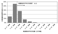
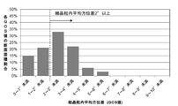
結晶粒内平均方位差(GOS値)は、CrとAlの複合窒化物または複合炭窒化物層、または、TiとAlとMeの複合窒化物または複合炭窒化物層の表面に垂直な方向からその表面研磨面について電子線後方散乱回折装置を用いて、25×25μmの測定範囲内での測定を0.1μm/stepの間隔で、5視野で実施し、該複合窒化物または複合炭窒化物層を構成する立方晶構造を有する結晶粒に属する全ピクセル数を求め、結晶粒内平均方位差を1度間隔で分割し、その値の範囲内に結晶粒内平均方位差が含まれる結晶粒のピクセルを集計して上記全ピクセル数で割ることによって、結晶粒内平均方位差の面積割合を示すヒストグラムを作成する事によって求めることができる。
図3〜図6に、このようにして作成されたヒストグラムの一例を示す。
The average intergranular orientation difference (GOS value) is from the direction perpendicular to the surface of the Cr and Al composite nitride or composite carbonitride layer, or the Ti, Al and Me composite nitride or composite carbonitride layer. The surface polished surface was measured within a measurement range of 25 × 25 μm using an electron backscatter diffraction device at intervals of 0.1 μm / step in 5 visual fields, and the composite nitride or composite carbonitride was obtained. The total number of pixels belonging to the crystal grains having a cubic structure constituting the layer is obtained, the average orientation difference within the crystal grains is divided at 1 degree intervals, and the crystal grains having the average orientation difference within the crystal grains within the range of the values. It can be obtained by creating a histogram showing the area ratio of the average orientation difference in the crystal grains by totaling the pixels of the above and dividing by the total number of pixels.
3 to 6 show an example of the histogram created in this way.
図3は、本発明に係る切削工具のCrとAlの複合窒化物または複合炭窒化物層の立方晶構造を有する結晶粒について求めた、結晶粒内平均方位差のヒストグラムの一例であるが、図3に示されるように、結晶粒内平均方位差(GOS)の値が2度以上である結晶粒がCrとAlの複合窒化物または複合炭窒化物層の全面積に占める面積割合は20%以上であることが分かる。
これに対し、図4は、比較工具のCrとAlの複合窒化物または複合炭窒化物層の立方晶構造を有する結晶粒について求めた、結晶粒内平均方位差のヒストグラムの一例であるが、図4においては、結晶粒内平均方位差(GOS)の値が2度以上である結晶粒がCrとAlの複合窒化物または複合炭窒化物層の全面積に占める面積割合は20%未満である。
また、図5は、本発明に係る切削工具のTiとAlとMeの複合窒化物または複合炭窒化物層の立方晶構造を有する結晶粒について求めた、結晶粒内平均方位差のヒストグラムの一例であるが、図5に示されるように、結晶粒内平均方位差(GOS)の値が2度以上である結晶粒がTiとAlとMeの複合窒化物または複合炭窒化物層の全面積に占める面積割合は20%以上であることが分かる。
これに対して、図6は、比較工具のTiとAlとMeの複合窒化物または複合炭窒化物層の立方晶構造を有する結晶粒について求めた、結晶粒内平均方位差のヒストグラムの一例であるが、図6においては、結晶粒内平均方位差(GOS)の値が2度以上である結晶粒がTiとAlとMeの複合窒化物または複合炭窒化物層の全面積に占める面積割合は20%未満である。
このように、本発明に係る切削工具のCrとAlの複合窒化物または複合炭窒化物層、および、TiとAlとMeの複合窒化物または複合炭窒化物層を構成する立方晶構造を有する結晶粒は、
従来のものと比較して、結晶粒内で結晶方位のばらつきが大きく、そのため、結晶粒内での歪が高くなることが硬さと靱性の向上に寄与している。
そして、前記結晶粒内平均方位差を備える(Cr1−xAlx)(CyN1−y)層、または、(Ti1−α―βAlαMeβ)(CγN1−γ)層を少なくとも含む硬質被覆層を工具基体表面に被覆形成した被覆工具は、高熱発生を伴うとともに、切刃に対して衝撃的な負荷が作用する合金鋼等の高速断続切削加工で、すぐれた耐チッピング性と耐摩耗性を発揮するのである。
ただ、前記結晶粒内平均方位差が2度以上を示す結晶粒の、CrとAlの複合窒化物もしくは複合炭窒化物層、または、TiとAlとMeの複合窒化物もしくは複合炭窒化物層の全面積に占める面積割合が20%未満である場合には、結晶粒の内部歪による硬さと靱性の向上効果が十分でないことから、結晶粒内平均方位差が2度以上を示す立方晶構造を有する結晶粒がTiとAlとMeの複合窒化物または複合炭窒化物層の全面積に占める面積割合は20%以上とする。
このように本発明の表面被覆切削工具が有するAlとTiとMeの複合窒化物または複合炭窒化物層を構成する結晶粒は、従来のTiAlN層を構成している結晶粒と比較して、結晶粒内で結晶方位のばらつきが大きく、すなわち、歪みがあるため、このことが硬さや靭性の向上に寄与している。
好ましい複合窒化物または複合炭窒化物層の面積に対する、結晶粒内平均方位差が2度以上を示す結晶粒の面積割合は30〜60%である。より好ましい複合窒化物または複合炭窒化物層の面積に対する、結晶粒内平均方位差が2度以上を示す結晶粒の面積割合は35〜55%である。さらにより複合窒化物または複合炭窒化物層の面積に対する、結晶粒内平均方位差が2度以上を示す結晶粒の面積割合は40〜50%である。
FIG. 3 is an example of a histogram of the average orientation difference within the crystal grains obtained for the crystal grains having a cubic structure of the Cr and Al composite nitride or the composite carbonitride layer of the cutting tool according to the present invention. As shown in FIG. 3, the area ratio of the crystal grains having the average intergranular orientation difference (GOS) of 2 degrees or more to the total area of the Cr and Al composite nitride or composite carbonitride layer is 20. It turns out that it is more than%.
On the other hand, FIG. 4 shows an example of a histogram of the average orientation difference within the crystal grains obtained for the crystal grains having a cubic structure of the Cr and Al composite nitride or the composite carbonitride layer of the comparison tool. In FIG. 4, the area ratio of the crystal grains having an average intragranular orientation difference (GOS) of 2 degrees or more to the total area of the Cr and Al composite nitride or composite carbonitride layer is less than 20%. be.
Further, FIG. 5 shows an example of a histogram of the average orientation difference in the crystal grains obtained for the crystal grains having a cubic structure of the composite nitride or composite carbonitride layer of Ti, Al and Me of the cutting tool according to the present invention. However, as shown in FIG. 5, the total area of the composite nitride or composite carbonitride layer of Ti, Al, and Me in which the crystal grains have a value of the average intergranular orientation difference (GOS) of 2 degrees or more is 2 degrees or more. It can be seen that the area ratio to the above is 20% or more.
On the other hand, FIG. 6 shows an example of a histogram of average intergranular orientation differences obtained for crystal grains having a cubic structure of a composite nitride of Ti, Al, and Me of a comparative tool or a composite carbonitride layer. However, in FIG. 6, the area ratio of the crystal grains having the average intergranular orientation difference (GOS) of 2 degrees or more to the total area of the composite nitride or composite carbonitride layer of Ti, Al, and Me. Is less than 20%.
As described above, the cutting tool according to the present invention has a cubic structure constituting a Cr and Al composite nitride or composite carbonitride layer and a Ti, Al and Me composite nitride or composite carbonitride layer. Crystal grains are
Compared with the conventional ones, the variation in crystal orientation is large in the crystal grains, and therefore, the increase in strain in the crystal grains contributes to the improvement of hardness and toughness.
Then, the (Cr 1-x Al x ) (C y N 1-y ) layer having the average orientation difference in the crystal grains or (Ti 1-α-β Al α Me β ) (C γ N 1-γ) A coated tool in which a hard coating layer containing at least a layer is coated on the surface of the tool substrate is excellent in high-speed intermittent cutting of alloy steel or the like, which is accompanied by high heat generation and exerts a shocking load on the cutting edge. It exhibits chipping resistance and abrasion resistance.
However, a Cr and Al composite nitride or composite carbon nitride layer, or a Ti, Al, and Me composite nitride or composite carbon nitride layer of the crystal grains having an average intergranular difference of 2 degrees or more. When the area ratio to the total area of the crystal grains is less than 20%, the effect of improving the hardness and toughness due to the internal strain of the crystal grains is not sufficient. Therefore, the cubic crystal structure showing an average orientation difference within the crystal grains of 2 degrees or more. The area ratio of the crystal grains having the above to the total area of the composite nitride or composite carbon nitride layer of Ti, Al, and Me is 20% or more.
As described above, the crystal grains constituting the composite nitride or composite carbonitride layer of Al, Ti and Me possessed by the surface coating cutting tool of the present invention are compared with the crystal grains constituting the conventional TiAlN layer. Since the crystal orientation varies widely within the crystal grains, that is, there is distortion, this contributes to the improvement of hardness and toughness.
The area ratio of the crystal grains having an average intergranular orientation difference of 2 degrees or more with respect to the area of the preferable composite nitride or composite carbonitride layer is 30 to 60%. The area ratio of the crystal grains showing an average orientation difference within the crystal grains of 2 degrees or more with respect to the area of the more preferable composite nitride or composite carbonitride layer is 35 to 55%. Furthermore, the area ratio of the crystal grains showing an average orientation difference within the crystal grains of 2 degrees or more with respect to the area of the composite nitride or composite carbonitride layer is 40 to 50%.
複合窒化物または複合炭窒化物層を層厚方向に二等分した工具基体側の領域と表面側の領域における結晶方位:
複合窒化物または複合炭窒化物層を構成する結晶粒は、工具基体表面(工具基体)側よりも表面側の方が、工具基体表面の法線方向、すなわち{100}面に向いていることにより、靱性を維持しつつ、耐摩耗性が向上するという本発明に特有の効果が奏される。
しかしながら、工具基体側よりも表面側の{100}面配向度の増加割合が10%未満であると{100}面配向度の増加割合が少なく、本発明において期待する靱性を維持しつつ耐摩耗性を向上するという効果が十分に奏されない。一方、30%を超えると配向の急激な変化により結晶のエピタキシャル成長を阻害し、かえって靭性が低下する。また工具基体側の{100}面配向度が10%未満では表面側の{100}面配向度の増加割合が30%より大きくなり工具基体側の{100}面配向度が40%を超えると表面側の{100}面配向度の増加割合が10%未満となる事が分かった。したがって、結晶粒の工具基体表面の法線方向に対する結晶面である{100}面の法線がなす傾斜角を複合窒化物または複合炭窒化物層を層厚方向に二等分した工具基体側の領域と表面側の領域に分けて測定し、測定された前記傾斜角のうち法線方向に対して0〜45度の範囲内にある測定傾斜角を0.25度のピッチ毎に区分して各区分内に存在する度数を集計した場合、a)工具基体側の領域において、0〜12度の範囲内に存在する度数の合計が、傾斜角度数分布における度数全体に対しての割合をMdegとすると、Mdegが10〜40%であり、b)表面側の領域において、0〜12度の範囲内の傾斜角区分に最高ピークが存在すると共に、0〜12度の範囲内に存在する度数の合計が、傾斜角度数分布における度数全体に対しての割合をNdegとすると、NdegがMdeg+10〜Mdeg+30%であると定めた。
Crystal orientation in the region on the tool substrate side and the region on the surface side when the composite nitride or composite carbonitride layer is bisected in the layer thickness direction:
The crystal grains constituting the composite nitride or composite carbonitride layer are oriented toward the normal direction of the tool substrate surface, that is, the {100} plane, on the surface side rather than the tool substrate surface (tool substrate) side. As a result, the effect peculiar to the present invention is exhibited, that is, the abrasion resistance is improved while maintaining the toughness.
However, if the rate of increase in the {100} plane orientation on the surface side is less than 10% than that on the tool substrate side, the rate of increase in the {100} plane orientation is small, and wear resistance is maintained while maintaining the toughness expected in the present invention. The effect of improving sex is not sufficiently achieved. On the other hand, if it exceeds 30%, the epitaxial growth of the crystal is inhibited due to a sudden change in orientation, and the toughness is rather lowered. If the {100} plane orientation on the tool base side is less than 10%, the rate of increase in the {100} plane orientation on the surface side is greater than 30%, and if the {100} plane orientation on the tool base side exceeds 40%. It was found that the rate of increase in the degree of {100} plane orientation on the surface side was less than 10%. Therefore, the angle of inclination formed by the normal line of the {100} plane, which is the crystal plane with respect to the normal direction of the surface of the tool base of the crystal grains, is divided into two equal parts in the composite nitride or composite carbon nitride layer in the layer thickness direction on the tool base side. The measurement is divided into the area on the surface side and the area on the surface side, and the measurement inclination angle within the range of 0 to 45 degrees with respect to the normal direction among the measured inclination angles is divided into pitches of 0.25 degrees. When the degrees existing in each division are totaled, a) In the area on the tool base side, the total of the degrees existing in the range of 0 to 12 degrees is the ratio to the total degrees in the inclination angle number distribution. Assuming M deg , M deg is 10 to 40%, and b) in the region on the surface side, the highest peak exists in the inclination angle division within the range of 0 to 12 degrees, and within the range of 0 to 12 degrees. Assuming that the total number of existing degrees is N deg as a percentage of the total degrees in the inclination angle distribution , N deg is determined to be M deg + 10 to M deg + 30%.
硬質被覆層の結晶構造:
硬質被覆層が立方晶構造単相である場合、特に優れた耐摩耗性を示す。また、硬質被覆層が立方晶構造単相でない場合であっても、該硬質被覆層について、電子線後方散乱回折装置を用いて縦断面方向から0.1μm間隔で解析し、幅10μm、縦は膜厚の測定範囲内での縦断面方向からの測定を5視野で実施し、該複合窒化物または複合炭窒化物層を構成する立方晶構造を有する結晶粒に属する全ピクセル数を求め、前記5視野での該硬質被覆層に対する測定において全測定ピクセル数との比によって、該複合窒化物または複合炭窒化物層を構成する立方晶構造を有する結晶粒の面積割合を求めたとき、立方晶構造を有する結晶粒の面積割合が70%未満の場合には、耐摩耗性の低下傾向がみられ、一方、この面積割合が70%以上である場合には、すぐれた耐チッピング性、耐摩耗性が発揮されることから、立方晶構造のTiとAlとMeの複合窒化物または複合炭窒化物の相は、70面積%以上とすることが望ましい。
Crystal structure of hard coating layer:
When the hard coating layer is a cubic single-phase structure, it exhibits particularly excellent wear resistance. Further, even when the hard coating layer is not a cubic single-phase structure, the hard coating layer is analyzed at intervals of 0.1 μm from the longitudinal cross-sectional direction using an electron beam rear scattering diffractometer, and the width is 10 μm and the length is 10. The measurement from the longitudinal cross-sectional direction within the measurement range of the film thickness was carried out in five fields, and the total number of pixels belonging to the crystal grains having the cubic crystal structure constituting the composite nitride or the composite carbonic nitride layer was obtained. When the area ratio of the crystal grains having a cubic structure constituting the composite nitride or the composite carbon nitride layer was determined from the ratio to the total number of measured pixels in the measurement for the hard coating layer in five fields, the cubic crystal When the area ratio of the crystal grains having a structure is less than 70%, the wear resistance tends to decrease, while when the area ratio is 70% or more, excellent chipping resistance and abrasion resistance are observed. It is desirable that the phase of the composite nitride or composite carbon nitride of Ti, Al, and Me having a cubic structure is 70 area% or more because the property is exhibited.
複合窒化物または複合炭窒化物層内の立方晶構造を有する個々の結晶粒の平均粒子幅W、平均アスペクト比A:
CrとAlの複合窒化物もしくは複合炭窒化物層内、または、TiとAlとMeの複合窒化物もしくは複合炭窒化物層内の立方晶構造を有する個々の結晶粒の平均粒子幅Wが0.1〜2μm、平均アスペクト比Aが2〜10となる柱状組織となるように構成することにより、靭性および耐摩耗性が向上するという前述した効果をより一層、発揮させることができる。
すなわち、平均粒子幅Wを0.1〜2μmとしたのは、0.1μm未満では、被覆層表面に露出した原子におけるCrAlCN結晶粒界、または、TiAlMeCN結晶粒界に属する原子の占める割合が相対的に大きくなることにより、被削材との反応性が増し、その結果、耐摩耗性を十分に発揮することができず、また、2μmを超えると被覆層全体におけるCrAlCN結晶粒界、または、TiAlMeCN結晶粒界に属する原子の占める割合が相対的に小さくなることにより、靭性が低下し、耐チッピング性を十分に発揮することができなくなる。したがって、平均粒子幅Wを0.1〜2μmとすることが好ましい。
また、平均アスペクト比Aが2未満の場合、十分な柱状組織となっていないため、アスペクト比の小さな等軸結晶の脱落を招き、その結果、十分な耐摩耗性を発揮することができない。一方、平均アスペクト比Aが10を超えると結晶粒そのものの強度を保つ事が出来ず、かえって、耐チッピング性が低下するため好ましくない。したがって、平均アスペクト比Aを2〜10とすることが好ましい。
なお、本発明では、平均アスペクト比Aとは、走査型電子顕微鏡を用い、幅100μm、高さが硬質被覆層全体を含む範囲で硬質被覆層の縦断面観察を行った際に、工具基体表面と垂直な皮膜断面側から観察し、基体表面と平行な方向の粒子幅w、基体表面に垂直な方向の粒子長さlを測定し、各結晶粒のアスペクト比a(=l/w)を算出するとともに、個々の結晶粒について求めたアスペクト比aの平均値を平均アスペクト比Aとして算出し、また、個々の結晶粒について求めた粒子幅wの平均値を平均粒子幅Wとして算出した。
Average particle width W, average aspect ratio A: of individual crystal grains having a cubic structure in the composite nitride or composite carbonitride layer:
The average particle width W of each crystal grain having a cubic structure in the composite nitride or composite carbonitride layer of Cr and Al, or in the composite nitride or composite carbonitride layer of Ti, Al and Me is 0. By forming a columnar structure having an average aspect ratio of 2 to 10 and an average aspect ratio of 1 to 2 μm, the above-mentioned effect of improving toughness and wear resistance can be further exhibited.
That is, the reason why the average particle width W is 0.1 to 2 μm is that when the average particle width W is less than 0.1 μm, the proportion of atoms belonging to the CrAlCN grain boundaries or TiAlMeCN grain boundaries in the atoms exposed on the surface of the coating layer is relative. As a result, the reactivity with the work material is increased, and as a result, the abrasion resistance cannot be sufficiently exhibited, and when it exceeds 2 μm, the CrAlCN grain boundaries in the entire coating layer or the CrAlCN grain boundaries or Since the proportion of atoms belonging to the TiAlMeCN grain boundaries is relatively small, the toughness is lowered and the chipping resistance cannot be sufficiently exhibited. Therefore, it is preferable that the average particle width W is 0.1 to 2 μm.
Further, when the average aspect ratio A is less than 2, the columnar structure is not sufficient, which causes the equiaxed crystals having a small aspect ratio to fall off, and as a result, sufficient wear resistance cannot be exhibited. On the other hand, if the average aspect ratio A exceeds 10, the strength of the crystal grains themselves cannot be maintained, and on the contrary, the chipping resistance is lowered, which is not preferable. Therefore, it is preferable that the average aspect ratio A is 2 to 10.
In the present invention, the average aspect ratio A is defined as the surface of the tool substrate when the vertical cross section of the hard coating layer is observed in a range of 100 μm in width and 100 μm in height including the entire hard coating layer using a scanning electron microscope. Observe from the cross-sectional side of the film perpendicular to the substrate surface, measure the particle width w in the direction parallel to the substrate surface, and measure the particle length l in the direction perpendicular to the substrate surface, and determine the aspect ratio a (= l / w) of each crystal grain. In addition to the calculation, the average value of the aspect ratio a obtained for each crystal grain was calculated as the average aspect ratio A, and the average value of the particle width w obtained for each crystal grain was calculated as the average particle width W.
下部層および上部層:
また、本発明の表面被覆切削工具が有するCrとAlの複合窒化物もしくは複合炭窒化物層内、または、TiとAlとMeの複合窒化物もしくは複合炭窒化物層は、それだけでも十分な効果を奏するが、Tiの炭化物層、窒化物層、炭窒化物層、炭酸化物層および炭窒酸化物層のうちの1層または2層以上のTi化合物層からなり、0.1〜20μmの合計平均層厚を有する下部層を設けた場合、および/または、少なくとも酸化アルミニウム層を含む上部層を1〜25μmの合計平均層厚で設けた場合には、これらの層が奏する効果と相俟って、一層すぐれた特性を創出することができる。Tiの炭化物層、窒化物層、炭窒化物層、炭酸化物層および炭窒酸化物層のうちの1層または2層以上のTi化合物層からなる下部層を設ける場合、下部層の合計平均層厚が0.1μm未満では、下部層の効果が十分に奏されず、一方、20μmを超えると結晶粒が粗大化し易くなり、チッピングを発生しやすくなる。また、酸化アルミニウム層を含む上部層の合計平均層厚が1μm未満では、上部層の効果が十分に奏されず、一方、25μmを超えると結晶粒が粗大化し易くなり、チッピングを発生しやすくなる。
Lower and upper layers:
Further, the Cr and Al composite nitride or composite carbonitride layer, or the Ti, Al and Me composite nitride or composite carbonitride layer of the surface coating cutting tool of the present invention has a sufficient effect by itself. However, it is composed of one or more Ti compound layers of Ti carbide layer, nitride layer, carbonitride layer, coal oxide layer and carbonitride oxide layer, and has a total of 0.1 to 20 μm. When the lower layer having an average layer thickness is provided and / or when the upper layer including at least the aluminum oxide layer is provided with a total average layer thickness of 1 to 25 μm, the effects of these layers are combined. Therefore, it is possible to create even better characteristics. When a lower layer composed of one or more Ti compound layers of a carbide layer, a nitride layer, a carbonitride layer, a carbon oxide layer and a carbon dioxide oxide layer of Ti is provided, the total average layer of the lower layers is provided. If the thickness is less than 0.1 μm, the effect of the lower layer is not sufficiently exhibited, while if it exceeds 20 μm, the crystal grains are likely to be coarsened and chipping is likely to occur. Further, if the total average layer thickness of the upper layer including the aluminum oxide layer is less than 1 μm, the effect of the upper layer is not sufficiently exhibited, while if it exceeds 25 μm, the crystal grains are likely to be coarsened and chipping is likely to occur. ..
本発明の表面被覆切削工具が有する硬質被覆層を構成するCrとAlの複合窒化物もしくは複合炭窒化物層、または、TiとAlとMeの複合窒化物もしくは複合炭窒化物層の断面を模式的に表した図を図2に示す。 A schematic cross section of a Cr and Al composite nitride or composite carbonitride layer or a Ti, Al and Me composite nitride or composite carbonitride layer constituting the hard coating layer of the surface coating cutting tool of the present invention. The figure represented by the above is shown in FIG.
つぎに、本発明の被覆工具を実施例により具体的に説明する。
なお、実施例としては、WC基超硬合金あるいはTiCN基サーメットを工具基体とする被覆工具について述べるが、工具基体として立方晶窒化ホウ素基超高圧焼結体を用いた場合も同様である。
Next, the covering tool of the present invention will be specifically described with reference to Examples.
As an example, a coated tool using a WC-based cemented carbide or a TiCN-based cermet as a tool base will be described, but the same applies when a cubic boron nitride-based ultrahigh-pressure sintered body is used as the tool base.
原料粉末として、いずれも1〜3μmの平均粒径を有するWC粉末、TiC粉末、TaC粉末、NbC粉末、Cr3C2粉末およびCo粉末を用意し、これら原料粉末を、表1に示される配合組成に配合し、さらにワックスを加えてアセトン中で24時間ボールミル混合し、減圧乾燥した後、98MPaの圧力で所定形状の圧粉体にプレス成形し、この圧粉体を5Paの真空中、1370〜1470℃の範囲内の所定の温度に1時間保持の条件で真空焼結し、焼結後、ISO規格SEEN1203AFSNのインサート形状をもったWC基超硬合金製の工具基体A〜Cをそれぞれ製造した。 As raw material powders, WC powder, TiC powder, TaC powder, NbC powder, Cr 3 C 2 powder and Co powder having an average particle size of 1 to 3 μm are prepared, and these raw material powders are blended as shown in Table 1. It was blended into the composition, further added with wax, mixed in a ball mill in acetone for 24 hours, dried under reduced pressure, press-molded into a green compact having a predetermined shape at a pressure of 98 MPa, and this green powder was press-molded into a green compact of a predetermined shape in a vacuum of 5 Pa, 1370. Vacuum sintered at a predetermined temperature within the range of ~ 1470 ° C. under the condition of holding for 1 hour, and after sintering, manufacture tool bases A to C made of WC-based superhard alloy having an insert shape of ISO standard SEEN1203AFSN. bottom.
また、原料粉末として、いずれも0.5〜2μmの平均粒径を有するTiCN(質量比でTiC/TiN=50/50)粉末、Mo2C粉末、ZrC粉末、NbC粉末、WC粉
末、Co粉末およびNi粉末を用意し、これら原料粉末を、表2に示される配合組成に配合し、ボールミルで24時間湿式混合し、乾燥した後、98MPaの圧力で圧粉体にプレス成形し、この圧粉体を1.3kPaの窒素雰囲気中、温度:1500℃に1時間保持の条件で焼結し、焼結後、ISO規格SEEN1203AFSNのインサート形状をもったTiCN基サーメット製の工具基体Dを作製した。
Further, as the raw material powder, both (TiC / TiN = 50/50 in mass ratio) TiCN having an average particle diameter of 0.5~2μm powder, Mo 2 C powder, ZrC powder, NbC powder, WC powder, Co powder And Ni powder are prepared, these raw material powders are blended into the compounding composition shown in Table 2, wet-mixed with a ball mill for 24 hours, dried, and then press-molded into a green compact at a pressure of 98 MPa. The body was sintered in a nitrogen atmosphere of 1.3 kPa at a temperature of 1500 ° C. for 1 hour, and after sintering, a tool base D made of TiCN-based cermet having an insert shape of ISO standard SEEN1203AFSN was prepared.
つぎに、これらの工具基体A〜Dの表面に、化学蒸着装置を用い、
表3および表4、表5に示される形成条件A〜J、すなわち、NH3とH2からなるガス群Aと、CrCl3、AlCl3、Al(CH3)3、N2、H2からなるガス群B、およびおのおのガスの供給方法として、反応ガス組成(ガス群Aおよびガス群Bを合わせた全体に対する容量%)を、ガス群AとしてNH3:4.5〜5.5%、H2:65〜75%、ガス群BとしてAlCl3:0.6〜0.9%、CrCl3:0.2〜0.3%、Al(CH3)3:0〜0.5%、N2:12.5〜15.0%、H2:残、反応雰囲気圧力:4.5〜5.0kPa、反応雰囲気温度:750〜900℃、供給周期1〜5秒、1周期当たりのガス供給時間0.15〜0.25秒、ガス群Aとガス群Bの供給の位相差0.10〜0.20秒として、所定時間、熱CVD法を行い、表7に示される結晶粒内平均方位差が2度以上を示す立方晶構造を有する結晶粒が表7に示される面積割合存在し、表7に示される目標層厚を有する(Cr1−xAlx)(CyN1−y)層からなる硬質被覆層を形成することにより本発明被覆工具1〜15を製造した。
なお、本発明被覆工具6〜13については、表3に示される形成条件で、表6に示される下部層および/または表7に示される上部層を形成した。
Next, a chemical vapor deposition apparatus was used on the surfaces of these tool bases A to D.
From the formation conditions A to J shown in Tables 3, 4 and 5, that is, the gas group A consisting of NH 3 and H 2 , and CrCl 3 , AlCl 3 , Al (CH 3 ) 3 , N 2 , and H 2. As a method of supplying the gas group B and each gas, the reaction gas composition (capacity% of the total of the gas group A and the gas group B combined) was used as the gas group A, and NH 3 : 4.5 to 5.5%, respectively. H 2 : 65-75%, as gas group B AlCl 3 : 0.6-0.9%, CrCl 3 : 0.2-0.3%, Al (CH 3 ) 3 : 0-0.5%, N 2 : 12.5 to 15.0%, H 2 : Residual, reaction atmosphere pressure: 4.5 to 5.0 kPa, reaction atmosphere temperature: 750 to 900 ° C,
For the
また、比較の目的で、工具基体A〜Dの表面に、表3および表4、表5に示される条件かつ表8に示される目標層厚(μm)で本発明被覆工具1〜15と同様に、少なくともCrとAlの複合窒化物または複合炭窒化物層を含む硬質被覆層を蒸着形成した。この時には、(Cr1−xAlx)(CyN1−y)層の成膜工程中に工具基体表面における反応ガス組成が時間的に変化しない様に硬質被覆層を形成することにより比較被覆工具1〜13を製造した。
なお、本発明被覆工具6〜13と同様に、比較被覆工具6〜13については、表3に示される形成条件で、表6に示される下部層および/または表8に示される上部層を形成した。
Further, for the purpose of comparison, the same conditions as those of the
Similar to the
参考のため、工具基体Bおよび工具基体Cの表面に、従来の物理蒸着装置を用いて、アークイオンプレーティングにより、参考例の(Cr1−xAlx)(CyN1−y)層を目標層厚で蒸着形成することにより、表8に示される参考被覆工具14、15を製造した。
なお、参考例の蒸着に用いたアークイオンプレーティングの条件は、次のとおりである。
(a)前記工具基体BおよびCを、アセトン中で超音波洗浄し、乾燥した状態で、アークイオンプレーティング装置内の回転テーブル上の中心軸から半径方向に所定距離離れた位置に外周部に沿って装着し、また、カソード電極(蒸発源)として、所定組成のAl−Cr合金を配置し、
(b)まず、装置内を排気して10−2Pa以下の真空に保持しながら、ヒーターで装置内を500℃に加熱した後、前記回転テーブル上で自転しながら回転する工具基体に−1000Vの直流バイアス電圧を印加し、かつAl−Cr合金からなるカソード電極とアノード電極との間に200Aの電流を流してアーク放電を発生させ、装置内にAlおよびCrイオンを発生させ、もって工具基体表面をボンバード洗浄し、
(c)次に、装置内に反応ガスとして窒素ガスを導入して4Paの反応雰囲気とすると共に、前記回転テーブル上で自転しながら回転する工具基体に−50Vの直流バイアス電圧を印加し、かつ、前記Al−Cr合金からなるカソード電極(蒸発源)とアノード電極との間に120Aの電流を流してアーク放電を発生させ、前記工具基体の表面に、表8に示される目標組成、目標層厚の(Cr,Al)N層を蒸着形成し、参考被覆工具14、15を製造した。
For reference, the (Cr 1-x Al x ) ( Cy N 1-y ) layer of the reference example is applied to the surfaces of the tool base B and the tool base C by arc ion plating using a conventional physical vapor deposition apparatus. The
The conditions of the arc ion plating used for the vapor deposition of the reference example are as follows.
(A) The tool substrates B and C are ultrasonically cleaned in acetone, dried, and placed on the outer peripheral portion at a position radially separated from the central axis on the rotary table in the arc ion plating apparatus by a predetermined distance. It is mounted along the line, and an Al—Cr alloy having a predetermined composition is arranged as a cathode electrode (evaporation source).
(B) First, while holding by evacuating the system to 10 -2 Pa or less of vacuum, after heating the inside of the apparatus to 500 ° C. by the heater, the tool substrate that rotates while rotating on the turntable -1000V A DC bias voltage is applied, and a current of 200 A is passed between the cathode electrode and the anode electrode made of Al—Cr alloy to generate an arc discharge, and Al and Cr ions are generated in the apparatus. Clean the surface with a bomber
(C) Next, nitrogen gas is introduced as a reaction gas into the apparatus to create a reaction atmosphere of 4 Pa, and a DC bias voltage of -50 V is applied to the tool substrate that rotates while rotating on the rotary table. An arc discharge is generated by passing a current of 120 A between the cathode electrode (evaporation source) made of the Al—Cr alloy and the anode electrode, and the target composition and target layer shown in Table 8 are formed on the surface of the tool substrate. A thick (Cr, Al) N layer was formed by vapor deposition to manufacture
また、本発明被覆工具1〜15、比較被覆工具1〜13および参考被覆工具14、15の各構成層の工具基体に垂直な方向の断面を、走査型電子顕微鏡(倍率5000倍)を用いて測定し、観察視野内の5点の層厚を測って平均して平均層厚を求めたところ、いずれも表7および表8に示される目標層厚と実質的に同じ平均層厚を示した。
Further, using a scanning electron microscope (magnification: 5000 times), a cross section of each of the constituent layers of the
また、複合窒化物または複合炭窒化物層のAlの平均含有割合xavgについては、電子線マイクロアナライザ(Electron−Probe−Micro−Analyser:EPMA)を用い、表面を研磨した試料において、電子線を試料表面側から照射し、得られた特性X線の解析結果の10点平均からAlの平均含有割合xavgを求めた。Cの平均含有割合yavgについては、二次イオン質量分析(Secondary−Ion−Mass−Spectroscopy:SIMS)により求めた。イオンビームを試料表面側から70μm×70μmの範囲に照射し、スパッタリング作用によって放出された成分について深さ方向の濃度測定を行った。Cの平均含有割合yavgはCrとAlの複合窒化物または複合炭窒化物層についての深さ方向の平均値を示す。ただしCの含有割合には、意図的にガス原料としてCを含むガスを用いなくても含まれる不可避的なCの含有割合を除外している。具体的にはAl(CH3)3の供給量を0とした場合の複合窒化物または複合炭窒化物層に含まれるC成分の含有割合(原子比)を不可避的なCの含有割合として求め、Al(CH3)3を意図的に供給した場合に得られる複合窒化物または複合炭窒化物層に含まれるC成分の含有割合(原子比)から前記不可避的なCの含有割合を差し引いた値をyavgとして求めた。 Regarding the average Al content x avg of the composite nitride or composite carbon nitride layer, an electron probe was used in a sample whose surface was polished using an electron probe microanalyzer (EPMA). Irradiation was performed from the sample surface side, and the average Al content ratio x avg was obtained from the 10-point average of the obtained characteristic X-ray analysis results. The average content ratio of C, yavg , was determined by secondary ion mass spectrometry (Secondary-Ion-Mass-Spectroscopy: SIMS). An ion beam was irradiated in a range of 70 μm × 70 μm from the sample surface side, and the concentration of the component released by the sputtering action was measured in the depth direction. The average content ratio y avg of C indicates the average value in the depth direction for the composite nitride or composite carbonitride layer of Cr and Al. However, the content ratio of C excludes the unavoidable content ratio of C contained even if a gas containing C is not intentionally used as a gas raw material. Specifically, the content ratio (atomic ratio) of the C component contained in the composite nitride or composite carbonitride layer when the supply amount of Al (CH 3 ) 3 is 0 is determined as the unavoidable C content ratio. , Al (CH 3 ) 3 was intentionally supplied, and the unavoidable C content ratio was subtracted from the C component content ratio (atomic ratio) contained in the composite nitride or composite carbonitride layer. The value was calculated as y avg.
さらに、電子線後方散乱回折装置を用いてCrとAlの複合窒化物または複合炭窒化物層を構成する立方晶構造を有する個々の結晶粒の結晶方位を縦断面方向から解析し、隣接するピクセル間で5度以上の方位差がある場合、そこを粒界とし、粒界で囲まれた領域を1つの結晶粒とし、結晶粒内のあるピクセルと、同一結晶粒内の他のすべてのピクセル間で結晶粒内方位差を求め、結晶粒内方位差が0度以上1度未満、1度以上2度未満、2度以上3度未満、3度以上4度未満、・・・と0〜10度の範囲を1度ごとに区切って、マッピングした。そのマッピング図から、結晶粒内平均方位差が2度以上となる結晶粒がCrとAlの複合窒化物または複合炭窒化物層全体に占める面積割合を求めた。
その結果を表7および表8に示す。
図3に、本発明被覆工具5について測定した結晶粒内平均方位差(すなわちGOS値)のヒストグラムの一例を示し、また、図4には、比較被覆工具2について測定した結晶粒内平均方位差のヒストグラムの一例を示す。
Further, using an electron beam backscattering diffractometer, the crystal orientation of each crystal grain having a cubic structure constituting a Cr and Al composite nitride or composite carbon nitride layer is analyzed from the longitudinal cross-sectional direction, and adjacent pixels are analyzed. If there is an orientation difference of 5 degrees or more between them, that is the grain boundary, the area surrounded by the grain boundaries is one crystal grain, and one pixel in the crystal grain and all other pixels in the same crystal grain. The intergranular orientation difference is calculated between 0 degrees and less than 1 degree, and the intergranular orientation difference is 0 degrees or more and less than 1 degree, 1 degree or more and less than 2 degrees, 2 degrees or more and less than 3 degrees, 3 degrees or more and less than 4 degrees, and so on. The range of 10 degrees was divided by each degree and mapped. From the mapping diagram, the area ratio of the crystal grains having an average orientation difference of 2 degrees or more in the crystal grains to the entire composite nitride or composite carbonitride layer of Cr and Al was determined.
The results are shown in Tables 7 and 8.
FIG. 3 shows an example of a histogram of the average intragranular orientation difference (that is, GOS value) measured for the
また、硬質被覆層の傾斜角度数分布については、立方晶構造のCrとAlの複合炭窒化物層からなる硬質被覆層の断面を研磨面とした状態で、電界放出型走査電子顕微鏡の鏡筒内にセットし、前記研磨面を層厚方向に二等分した工具基体表面(界面)側の領域と表面側の領域に分けて解析し、70度の入射角度で10kVの加速電圧の電子線を1nAの照射電流で、工具基体と垂直方向に関しては前記工具基体側の領域と表面側の領域の測定範囲内、工具基体と水平方向には幅10μm、5視野分について、0.1μm/stepの間隔で、測定範囲内に存在する立方晶結晶格子を有する結晶粒個々に照射し、電子線後方散乱回折像装置を用いて、工具基体表面の法線(断面研磨面における工具基体表面と垂直な方向)に対して、前記結晶粒の結晶面である{100}面の法線がなす傾斜角を測定し、この測定結果に基づいて、前記測定傾斜角のうち、0〜45度の範囲内にある測定傾斜角を0.25度のピッチ毎に区分すると共に、各区分内に存在する度数を集計することにより、0〜12度の範囲内に存在する度数の割合を求めた。その結果を表7および表8に示す。
図7に、本発明被覆工具のCrとAlの複合炭窒化物層からなる硬質被覆層の工具基体側の領域について測定した傾斜角度数分布の一例を示し、また、図8には、本発明被覆工具のCrとAlの複合炭窒化物層からなる硬質被覆層の表面側の領域について測定した傾斜角度数分布の一例を示す。
さらに電子線後方散乱回折装置を用いて縦断面方向から0.1μm間隔で解析し、幅10μm、縦は膜厚の測定範囲内での縦断面方向からの測定を5視野で実施し、該複合窒化物または複合炭窒化物層を構成する立方晶構造を有する結晶粒に属する全ピクセル数を求め、前記5視野での該硬質被覆層に対する測定において全測定ピクセル数との比によって、該複合窒化物または複合炭窒化物層を構成する立方晶構造を有する結晶粒の面積割合を求めた。
Regarding the distribution of the number of tilt angles of the hard coating layer, the lens barrel of the electric field emission type scanning electron microscope with the cross section of the hard coating layer composed of the Cr and Al composite carbonic nitride layer having a cubic structure as the polished surface. The polished surface is divided into two equal parts in the layer thickness direction, the area on the surface (interfacial) side of the tool substrate and the area on the surface side, and the analysis is performed. With an irradiation current of 1 nA, within the measurement range of the region on the tool substrate side and the region on the surface side in the direction perpendicular to the tool substrate, the width is 10 μm in the horizontal direction with the tool substrate, and 0.1 μm / step for 5 fields. The normals of the tool substrate surface (perpendicular to the tool substrate surface on the cross-section polished surface) are irradiated to each crystal grain having a cubic crystal lattice existing in the measurement range at intervals of. The inclination angle formed by the normal of the {100} plane, which is the crystal plane of the crystal grain, is measured, and based on the measurement result, the measurement inclination angle is in the range of 0 to 45 degrees. The measurement inclination angle inside was divided into pitches of 0.25 degrees, and the frequencies existing in each division were totaled to obtain the ratio of the frequencies existing in the range of 0 to 12 degrees. The results are shown in Tables 7 and 8.
FIG. 7 shows an example of the inclination angle number distribution measured for the region on the tool substrate side of the hard coating layer composed of the Cr and Al composite carbide nitride layer of the coating tool of the present invention, and FIG. 8 shows the present invention. An example of the inclination angle number distribution measured for the region on the surface side of the hard coating layer composed of the Cr and Al composite carbonitride layer of the coating tool is shown.
Further, analysis was performed at intervals of 0.1 μm from the longitudinal cross-sectional direction using an electron beam backscattering diffractometer, and measurements from the longitudinal cross-sectional direction within the measurement range of
つぎに、前記各種の被覆工具をいずれもカッタ径125mmの工具鋼製カッタ先端部に固定治具にてクランプした状態で、本発明被覆工具1〜15、比較被覆工具1〜13および参考被覆工具14,15について、以下に示す、炭素鋼の高速断続切削の一種である乾式高速正面フライス、センターカット切削加工試験を実施し、切刃の逃げ面摩耗幅を測定した。その結果を表9に示す。
Next, in a state where all of the above-mentioned various covering tools are clamped to the tip of a tool steel cutter having a cutter diameter of 125 mm with a fixing jig, the
工具基体:炭化タングステン基超硬合金、炭窒化チタン基サーメット、
切削試験:乾式高速正面フライス、センターカット切削加工、
被削材:JIS・S55C幅100mm、長さ400mmのブロック材、
回転速度:866 min−1、
切削速度:340 m/min、
切り込み:1.5 mm、
一刃送り量:0.10 mm/刃、
切削時間:8分、
Tool Base: Tungsten Carbide Cemented Carbide, Titanium Nitride Cermet,
Cutting test: Dry high-speed face milling cutter, center cut cutting,
Work material: JIS / S55C block material with a width of 100 mm and a length of 400 mm,
Rotation speed: 866 min -1 ,
Cutting speed: 340 m / min,
Notch: 1.5 mm,
Single blade feed amount: 0.10 mm / blade,
Cutting time: 8 minutes,
原料粉末として、いずれも1〜3μmの平均粒径を有するWC粉末、TiC粉末、ZrC粉末、TaC粉末、NbC粉末、Cr3C2粉末、TiN粉末およびCo粉末を用意し、これら原料粉末を、表10に示される配合組成に配合し、さらにワックスを加えてアセトン中で24時間ボールミル混合し、減圧乾燥した後、98MPaの圧力で所定形状の圧粉体にプレス成形し、この圧粉体を5Paの真空中、1370〜1470℃の範囲内の所定の温度に1時間保持の条件で真空焼結し、焼結後、切刃部にR:0.07mmのホーニング加工を施すことによりISO規格CNMG120412のインサート形状をもったWC基超硬合金製の工具基体α〜γをそれぞれ製造した。 As raw material powders, both WC powder having an average particle size of 1 to 3 [mu] m, TiC powder, ZrC powder, TaC powder, NbC powder, Cr 3 C 2 powder, prepared TiN powder and Co powder, these raw material powders, It was blended to the blending composition shown in Table 10, further added with wax, mixed in a ball mill in acetone for 24 hours, dried under reduced pressure, and then press-molded into a green compact having a predetermined shape at a pressure of 98 MPa to obtain this green compact. In a vacuum of 5 Pa, vacuum sintering is performed under the condition of holding at a predetermined temperature in the range of 1370 to 1470 ° C. for 1 hour. Tool bases α to γ made of WC-based superhard alloy having an insert shape of CNMG120412 were manufactured.
また、原料粉末として、いずれも0.5〜2μmの平均粒径を有するTiCN(質量比でTiC/TiN=50/50)粉末、NbC粉末、WC粉末、Co粉末、およびNi粉末を用意し、これら原料粉末を、表11に示される配合組成に配合し、ボールミルで24時間湿式混合し、乾燥した後、98MPaの圧力で圧粉体にプレス成形し、この圧粉体を1.3kPaの窒素雰囲気中、温度:1500℃に1時間保持の条件で焼結し、焼結後、切刃部分にR:0.09mmのホーニング加工を施すことによりISO規格・CNMG120412のインサート形状をもったTiCN基サーメット製の工具基体δを形成した。 Further, as raw material powders, TiCN (TiC / TiN = 50/50 by mass ratio) powder, NbC powder, WC powder, Co powder, and Ni powder, each having an average particle size of 0.5 to 2 μm, were prepared. These raw material powders were blended into the compounding composition shown in Table 11, wet-mixed with a ball mill for 24 hours, dried, and then press-molded into a green compact at a pressure of 98 MPa, and the green compact was pressed with 1.3 kPa of nitrogen. TiCN group with insert shape of ISO standard CNMG120412 by sintering in atmosphere under the condition of holding at temperature: 1500 ° C for 1 hour, and after sintering, honing processing of R: 0.09 mm is applied to the cutting edge part. A tool base δ made of cermet was formed.
つぎに、これらの工具基体α〜γおよび工具基体δの表面に、化学蒸着装置を用い、実施例1と同様の方法により表3および表4、表5に示される条件で、少なくとも(Cr1−xAlx)(CyN1−y)層を含む硬質被覆層を目標層厚で蒸着形成することにより、表13に示される本発明被覆工具16〜30を製造した。
なお、本発明被覆工具19〜28については、表3に示される形成条件で、表12に示される下部層および/または表13に示される上部層を形成した。
Next, using a chemical vapor deposition apparatus on the surfaces of these tool substrates α to γ and the tool substrate δ, at least (Cr 1) under the conditions shown in Table 3, Table 4, and Table 5 by the same method as in Example 1. The coating tools 16 to 30 of the present invention shown in Table 13 were manufactured by forming a hard coating layer including a −x Al x ) ( Cy N 1-y) layer by vapor deposition with a target layer thickness.
For the covering tools 19 to 28 of the present invention, the lower layer shown in Table 12 and / or the upper layer shown in Table 13 were formed under the formation conditions shown in Table 3.
また、比較の目的で、同じく工具基体α〜γおよび工具基体δの表面に、通常の化学蒸着装置を用い、表3および表4、表5に示される条件かつ表14に示される目標層厚で本発明被覆工具と同様に硬質被覆層を蒸着形成することにより、表14に示される比較被覆工具16〜28を製造した。
なお、本発明被覆工具19〜28と同様に、比較被覆工具19〜28については、表3に示される形成条件で、表12に示される下部層および/または表14に示される上部層を形成した。
Further, for the purpose of comparison, the same chemical vapor deposition apparatus is used on the surfaces of the tool substrates α to γ and the tool substrate δ, and the conditions shown in Tables 3 and 4 and 5 and the target layer thickness shown in Table 14 are used. By forming a hard coating layer by vapor deposition in the same manner as the coating tool of the present invention, the comparative coating tools 16 to 28 shown in Table 14 were manufactured.
Similar to the covering tools 19 to 28 of the present invention, the comparative covering tools 19 to 28 form the lower layer shown in Table 12 and / or the upper layer shown in Table 14 under the formation conditions shown in Table 3. bottom.
参考のため、工具基体βおよび工具基体γの表面に、従来の物理蒸着装置を用いて、アークイオンプレーティングにより、参考例の(Cr1−xAlx)(CyN1−y)層を目標層厚で蒸着形成することにより、表14に示される参考被覆工具29,30を製造した。
なお、アークイオンプレーティングの条件は、実施例1に示される条件と同様の条件を用いた。
For reference, the (Cr 1-x Al x ) ( Cy N 1-y ) layer of the reference example is applied to the surfaces of the tool base β and the tool base γ by arc ion plating using a conventional physical vapor deposition apparatus. The
As the conditions for arc ion plating, the same conditions as those shown in Example 1 were used.
また、本発明被覆工具16〜30、比較被覆工具16〜28および参考被覆工具29,30の各構成層の断面を、走査電子顕微鏡(倍率5000倍)を用いて測定し、観察視野内の5点の層厚を測って平均して平均層厚を求めたところ、いずれも表13および表14に示される目標層厚と実質的に同じ平均層厚を示した。
Further, the cross sections of the constituent layers of the covering tools 16 to 30, the comparative covering tools 16 to 28, and the
さらに、電子線後方散乱回折装置を用いてCrとAlの複合窒化物または複合炭窒化物層を構成する立方晶構造を有する個々の結晶粒の結晶方位を縦断面方向から解析し、結晶粒内方位差が0度以上1度未満、1度以上2度未満、2度以上3度未満、3度以上4度未満、・・・と0〜10度の範囲を1度ごとに区切って、マッピングした。そのマッピング図から、結晶粒内平均方位差と結晶粒内方位差が2度以上となる結晶粒がCrとAlの複合窒化物または複合炭窒化物層全体に占める面積割合を求めた。その結果を表13および表14に示す。 Further, using an electron backscatter diffraction device, the crystal orientation of each crystal grain having a cubic structure constituting a Cr and Al composite nitride or composite carbonitride layer is analyzed from the longitudinal cross-sectional direction, and the inside of the crystal grain is analyzed. The orientation difference is 0 degrees or more and less than 1 degree, 1 degree or more and less than 2 degrees, 2 degrees or more and less than 3 degrees, 3 degrees or more and less than 4 degrees, and so on. bottom. From the mapping diagram, the area ratio of the crystal grains having the average intergranular orientation difference and the intergranular orientation difference of 2 degrees or more in the entire composite nitride or composite carbonitride layer of Cr and Al was determined. The results are shown in Tables 13 and 14.
また、硬質被覆層の傾斜角度数分布については、立方晶構造のCrとAlの複合炭窒化物層からなる硬質被覆層の断面を研磨面とした状態で、電界放出型走査電子顕微鏡の鏡筒内にセットし、前記研磨面を層厚方向に二等分した工具基体表面(界面)側の領域と表面側の領域に分けて解析し、70度の入射角度で10kVの加速電圧の電子線を1nAの照射電流で、前記工具基体側の領域と表面側の領域の測定範囲内に存在する立方晶結晶格子を有する結晶粒個々に照射し、電子線後方散乱回折像装置を用いて、工具基体と水平方向に幅10μm、5視野分について、0.1μm/stepの間隔で、工具基体表面の法線(断面研磨面における工具基体表面と垂直な方向)に対して、前記結晶粒の結晶面である{100}面の法線がなす傾斜角を測定し、この測定結果に基づいて、前記測定傾斜角のうち、0〜45度の範囲内にある測定傾斜角を0.25度のピッチ毎に区分すると共に、各区分内に存在する度数を集計することにより、0〜12度の範囲内に存在する度数の割合を求めた。その結果を表13および表14に示す。 Regarding the distribution of the number of tilt angles of the hard coating layer, the lens barrel of the electric field emission type scanning electron microscope with the cross section of the hard coating layer composed of the Cr and Al composite carbonic nitride layer having a cubic structure as the polished surface. The polished surface is divided into two equal parts in the layer thickness direction, the area on the surface (interfacial) side of the tool substrate and the area on the surface side, and the analysis is performed. Is irradiated to each crystal grain having a cubic crystal lattice existing in the measurement range of the region on the tool substrate side and the region on the surface side with an irradiation current of 1 nA, and the tool is used by using an electron backscatter diffraction image device. Crystals of the crystal grains with respect to the normal of the tool substrate surface (direction perpendicular to the tool substrate surface on the cross-sectional polished surface) at intervals of 0.1 μm / step for a width of 10 μm in the horizontal direction with the substrate and for 5 fields. The inclination angle formed by the normal of the {100} plane, which is a surface, is measured, and based on this measurement result, the measurement inclination angle within the range of 0 to 45 degrees among the measurement inclination angles is set to 0.25 degrees. The ratio of the frequencies existing in the range of 0 to 12 degrees was obtained by classifying each pitch and totaling the frequencies existing in each division. The results are shown in Tables 13 and 14.
つぎに、前記各種の被覆工具をいずれも工具鋼製バイトの先端部に固定治具にてネジ止めした状態で、本発明被覆工具16〜30、比較被覆工具16〜28および参考被覆工具29,30について、以下に示す、炭素鋼の乾式高速断続切削試験、ダクタイル鋳鉄の湿式高速断続切削試験を実施し、いずれも切刃の逃げ面摩耗幅を測定した。
切削条件1:
被削材:JIS・S15Cの長さ方向等間隔4本縦溝入り丸棒、
切削速度:430m/min、
切り込み:1.5mm、
送り:0.22mm/rev、
切削時間:5分、
(通常の切削速度は、220m/min)、
切削条件2:
被削材:JIS・FCD450の長さ方向等間隔4本縦溝入り丸棒、
切削速度:410m/min、
切り込み:1.0mm、
送り:0.22mm/rev、
切削時間:5分、
(通常の切削速度は、200m/min)、
表15に、前記切削試験の結果を示す。
Next, in a state where all of the above-mentioned various covering tools are screwed to the tip of the tool steel cutting tool with a fixing jig, the covering tools 16 to 30, the comparative covering tools 16 to 28, and the reference covering tools 29, A dry high-speed intermittent cutting test for carbon steel and a wet high-speed intermittent cutting test for ductile cast iron were carried out for No. 30, and the flank wear width of the cutting edge was measured in each case.
Cutting condition 1:
Work material: JIS / S15C round bar with 4 vertical grooves at equal intervals in the length direction,
Cutting speed: 430 m / min,
Notch: 1.5 mm,
Feed: 0.22 mm / rev,
Cutting time: 5 minutes,
(Normal cutting speed is 220 m / min),
Cutting condition 2:
Work material: JIS / FCD450 round bar with 4 vertical grooves at equal intervals in the length direction,
Cutting speed: 410 m / min,
Notch: 1.0 mm,
Feed: 0.22 mm / rev,
Cutting time: 5 minutes,
(Normal cutting speed is 200m / min),
Table 15 shows the results of the cutting test.
表9、表15に示される結果から、本発明の被覆工具は、硬質被覆層を構成するAlとCrの複合窒化物または複合炭窒化物層を構成する立方晶構造を有する結晶粒内において、所定の結晶粒内平均方位差が存在するとともに、結晶粒の工具基体側の領域と表面側の領域で{100}面の法線がなす傾斜角が所定の傾斜角度数分布を有することで、結晶粒の歪みにより、硬さが向上し、高い耐摩耗性を保ちつつ、靱性が向上する。しかも、切れ刃に断続的・衝撃的高負荷が作用する高速断続切削加工に用いた場合でも、耐チッピング性、耐欠損性にすぐれ、その結果、長期の使用に亘ってすぐれた耐摩耗性を発揮することが明らかである。 From the results shown in Tables 9 and 15, the coating tool of the present invention has an Al and Cr composite nitride constituting a hard coating layer or a crystal grain having a cubic structure constituting a composite carbonic nitride layer. There is a predetermined average orientation difference within the crystal grains, and the inclination angle formed by the normal of the {100} plane between the region on the tool substrate side and the region on the surface side of the crystal grains has a predetermined inclination angle number distribution. Due to the strain of the crystal grains, the hardness is improved, and the toughness is improved while maintaining high wear resistance. Moreover, it has excellent chipping resistance and fracture resistance even when used for high-speed intermittent cutting in which an intermittent and shocking high load acts on the cutting edge, and as a result, excellent wear resistance over a long period of use. It is clear that it works.
これに対して、硬質被覆層を構成するAlとCrの複合窒化物または複合炭窒化物層を構成する立方晶構造を有する結晶粒内において、所定の結晶粒内平均方位差が存在していないか、結晶粒の工具基体側の領域と表面側の領域で{100}面の法線がなす傾斜角が所定の傾斜角度数分布を有していない比較被覆工具1〜13、16〜28および参考被覆工具14、15、29、30については、高熱発生を伴い、しかも、切れ刃に断続的・衝撃的高負荷が作用する高速断続切削加工に用いた場合、チッピング、欠損等の発生により短時間で寿命にいたることが明らかである。
On the other hand, there is no predetermined intra-grain average orientation difference in the crystal grains having a cubic structure forming the composite nitride of Al and Cr forming the hard coating layer or the composite carbon nitride layer. Alternatively, the
原料粉末として、いずれも1〜3μmの平均粒径を有するWC粉末、TiC粉末、TaC粉末、NbC粉末、Cr3C2粉末およびCo粉末を用意し、これら原料粉末を、表16に示される配合組成に配合し、さらにワックスを加えてアセトン中で24時間ボールミル混合し、減圧乾燥した後、98MPaの圧力で所定形状の圧粉体にプレス成形し、この圧粉体を5Paの真空中、1370〜1470℃の範囲内の所定の温度に1時間保持の条件で真空焼結し、焼結後、ISO規格SEEN1203AFSNのインサート形状をもったWC基超硬合金製の工具基体E〜Gをそれぞれ製造した。 As raw material powders, WC powder, TiC powder, TaC powder, NbC powder, Cr 3 C 2 powder and Co powder having an average particle size of 1 to 3 μm are prepared, and these raw material powders are blended as shown in Table 16. It was blended into the composition, further added with wax, mixed in a ball mill in acetone for 24 hours, dried under reduced pressure, press-molded into a green compact having a predetermined shape at a pressure of 98 MPa, and this green powder was press-molded into a green compact of a predetermined shape in a vacuum of 5 Pa, 1370. Vacuum sintered at a predetermined temperature within the range of ~ 1470 ° C. under the condition of holding for 1 hour, and after sintering, manufacture tool bases E to G made of WC-based superhard alloy having an insert shape of ISO standard SEEN1203AFSN. bottom.
また、原料粉末として、いずれも0.5〜2μmの平均粒径を有するTiCN(質量比でTiC/TiN=50/50)粉末、Mo2C粉末、ZrC粉末、NbC粉末、WC粉末、Co粉末およびNi粉末を用意し、これら原料粉末を、表17に示される配合組成に配合し、ボールミルで24時間湿式混合し、乾燥した後、98MPaの圧力で圧粉体にプレス成形し、この圧粉体を1.3kPaの窒素雰囲気中、温度:1500℃に1時間保持の条件で焼結し、焼結後、ISO規格SEEN1203AFSNのインサート形状をもったTiCN基サーメット製の工具基体Hを作製した。 Further, as the raw material powder, both (TiC / TiN = 50/50 in mass ratio) TiCN having an average particle diameter of 0.5~2μm powder, Mo 2 C powder, ZrC powder, NbC powder, WC powder, Co powder And Ni powder are prepared, these raw material powders are blended into the compounding composition shown in Table 17, wet-mixed with a ball mill for 24 hours, dried, and then press-molded into a green compact at a pressure of 98 MPa. The body was sintered in a nitrogen atmosphere of 1.3 kPa at a temperature of 1500 ° C. for 1 hour, and after sintering, a tool substrate H made of TiCN-based cermet having an insert shape of ISO standard SEEN1203AFSN was prepared.
つぎに、これらの工具基体E〜Hの表面に、化学蒸着装置を用い、表19、表20に示される形成条件、すなわち、NH3とH2からなるガス群Aと、TiCl4、Al(CH3)3、AlCl3、MeCln(但し、SiCl4,ZrCl4,BCl3,VCl4,CrCl2のうちのいずれか)、N2、H2からなるガス群B、およびおのおのガスの供給方法として、反応ガス組成(ガス群Aおよびガス群Bを合わせた全体に対する容量%)を、ガス群AとしてNH3:4.0〜6.0%、H2:65〜75%、ガス群BとしてAlCl3:0.6〜0.9%、TiCl4:0.2〜0.3%、Al(CH3)3:0〜0.5%、MeCln(但し、SiCl4,ZrCl4,BCl3,VCl4,CrCl2のうちのいずれか):0.1〜0.2%、N2:12.5〜15.0%、H2:残、反応雰囲気圧力:4.5〜5.0kPa、反応雰囲気温度:700〜900℃、供給周期1〜5秒、1周期当たりのガス供給時間0.15〜0.25秒、ガス群Aとガス群Bの供給の位相差0.10〜0.20秒として、所定時間、熱CVD法を行い、表22に示される結晶粒内平均方位差が2度以上を示す立方晶構造を有する結晶粒が表22に示される面積割合存在し、表22に示される目標層厚を有する(Ti1−α―βAlαMeβ)(CγN1−γ)層からなる硬質被覆層を形成することにより本発明被覆工具31〜45を製造した。
なお、本発明被覆工具36〜43については、表18に示される形成条件で、表21に示される下部層および/または表22に示される上部層を形成した。
Next, using a chemical vapor deposition apparatus on the surfaces of these tool substrates E to H, the formation conditions shown in Tables 19 and 20, that is, the gas group A composed of NH 3 and H 2 , and TiCl 4 and Al ( CH 3 ) 3 , AlCl 3 , MeCl n (however, any of SiCl 4 , ZrCl 4 , BCl 3 , VCl 4 , CrCl 2 ), gas group B consisting of N 2 , H 2 , and gas supply, respectively. As a method, the reaction gas composition (% by volume of the total of gas group A and gas group B) is adjusted to NH 3 : 4.0 to 6.0%, H 2 : 65 to 75%, and gas group as gas group A. As B, AlCl 3 : 0.6 to 0.9%, TiCl 4 : 0.2 to 0.3%, Al (CH 3 ) 3 : 0 to 0.5%, MeCl n (However, SiCl 4 , ZrCl 4) , BCl 3 , VCl 4 , CrCl 2 ) : 0.1 to 0.2%, N 2 : 12.5 to 15.0%, H 2 : Residual, Reaction Atmospheric Pressure: 4.5 to 5.0 kPa, reaction atmosphere temperature: 700 to 900 ° C.,
For the covering tools 36 to 43 of the present invention, the lower layer shown in Table 21 and / or the upper layer shown in Table 22 were formed under the formation conditions shown in Table 18.
また、比較の目的で、工具基体E〜Hの表面に、表19、表20に示される条件かつ表23に示される目標層厚(μm)で本発明被覆工具31〜45と同様に、少なくともTiとAlとMeの複合窒化物または複合炭窒化物層を含む硬質被覆層を蒸着形成した。この時には、(Ti1−α―βAlαMeβ)(CγN1−γ)層の成膜工程中に工具基体表面における反応ガス組成が時間的に変化しない様に硬質被覆層を形成することにより比較被覆工具31〜45を製造した。
なお、本発明被覆工具36〜43と同様に、比較被覆工具36〜43については、表18に示される形成条件で、表21に示される下部層および/または表23に示される上部層を形成した。
Further, for the purpose of comparison, at least on the surfaces of the tool substrates E to H, under the conditions shown in Tables 19 and 20 and the target layer thickness (μm) shown in Table 23, as in the case of the coated tools 31 to 45 of the present invention. A hard coating layer containing a composite nitride or composite carbonitride layer of Ti, Al, and Me was vapor-deposited. At this time, a hard coating layer is formed so that the reaction gas composition on the surface of the tool substrate does not change with time during the film forming process of the (Ti 1-α-β Al α Me β ) (C γ N 1-γ) layer. By doing so, comparative covering tools 31 to 45 were manufactured.
Similar to the covering tools 36 to 43 of the present invention, the comparative covering tools 36 to 43 form the lower layer shown in Table 21 and / or the upper layer shown in Table 23 under the formation conditions shown in Table 18. bottom.
また、本発明被覆工具31〜45、比較被覆工具31〜45の各構成層の工具基体に垂直な方向の断面を、走査型電子顕微鏡(倍率5000倍)を用いて測定し、観察視野内の5点の層厚を測って平均して平均層厚を求めたところ、いずれも表21〜表23に示される目標層厚と実質的に同じ平均層厚を示した。 Further, the cross section of each of the constituent layers of the covering tools 31 to 45 of the present invention and the comparative covering tools 31 to 45 in the direction perpendicular to the tool substrate was measured using a scanning electron microscope (magnification of 5000 times) and within the observation field. When the average layer thickness was obtained by measuring the layer thicknesses at five points and averaging them, all of them showed substantially the same average layer thickness as the target layer thickness shown in Tables 21 to 23.
また、複合窒化物または複合炭窒化物層の平均Al含有割合、平均Me含有割合については、電子線マイクロアナライザ(Electron−Probe−Micro−Analyser:EPMA)を用い、表面を研磨した試料において、電子線を試料表面側から照射し、得られた特性X線の解析結果の10点平均からAlの平均Al含有割合αavgおよびMeの平均含有割合βavgを求めた。平均C含有割合γavgについては、二次イオン質量分析(Secondary−Ion−Mass−Spectroscopy:SIMS)により求めた。イオンビームを試料表面側から70μm×70μmの範囲に照射し、スパッタリング作用によって放出された成分について深さ方向の濃度測定を行った。平均C含有割合γavgはTiとAlとMeの複合窒化物または複合炭窒化物層についての深さ方向の平均値を示す。ただしCの含有割合には、意図的にガス原料としてCを含むガスを用いなくても含まれる不可避的なCの含有割合を除外している。具体的にはAl(CH3)3の供給量を0とした場合の複合窒化物または複合炭窒化物層に含まれるC成分の含有割合(原子比)を不可避的なCの含有割合として求め、Al(CH3)3を意図的に供給した場合に得られる複合窒化物または複合炭窒化物層に含まれるC成分の含有割合(原子比)から前記不可避的なCの含有割合を差し引いた値をγavgとして求めた。その結果を表22および表23に示す。 Further, regarding the average Al content ratio and the average Me content ratio of the composite nitride or composite carbon nitride layer, the electrons are found in the sample whose surface is polished using an electron probe microanalyzer (EPMA). The line was irradiated from the surface side of the sample, and the average Al content ratio α avg of Al and the average content ratio β avg of Me were obtained from the 10-point average of the obtained characteristic X-ray analysis results. The average C content ratio γ avg was determined by secondary ion mass spectrometry (Secondary-Ion-Mass-Spectroscopy: SIMS). An ion beam was irradiated in a range of 70 μm × 70 μm from the sample surface side, and the concentration of the component released by the sputtering action was measured in the depth direction. The average C content ratio γ avg indicates the average value in the depth direction for the composite nitride or composite carbonitride layer of Ti, Al, and Me. However, the content ratio of C excludes the unavoidable content ratio of C contained even if a gas containing C is not intentionally used as a gas raw material. Specifically, the content ratio (atomic ratio) of the C component contained in the composite nitride or composite carbonitride layer when the supply amount of Al (CH 3 ) 3 is 0 is determined as the unavoidable C content ratio. , Al (CH 3 ) 3 was intentionally supplied, and the unavoidable C content ratio was subtracted from the C component content ratio (atomic ratio) contained in the composite nitride or composite carbonitride layer. The value was determined as γ avg . The results are shown in Tables 22 and 23.
さらに、電子線後方散乱回折装置を用いてTiとAlとMeの複合窒化物または複合炭窒化物層を構成する立方晶構造を有する個々の結晶粒の結晶方位を縦断面方向から解析し、隣接するピクセル間で5度以上の方位差がある場合、そこを粒界とし、粒界で囲まれた領域を1つの結晶粒とし、結晶粒内のあるピクセルと、同一結晶粒内の他のすべてのピクセル間で結晶粒内方位差を求め、結晶粒内方位差が0度以上1度未満、1度以上2度未満、2度以上3度未満、3度以上4度未満、・・・と0〜10度の範囲を1度ごとに区切って、マッピングした。そのマッピング図から、結晶粒内平均方位差が2度以上となる結晶粒がTiとAlとMeの複合窒化物または複合炭窒化物層全体に占める面積割合を求めた。その結果を表22および表23に示す。
図5に、本発明被覆工具について測定した結晶粒内平均方位差のヒストグラムの一例を示し、また、図6には、比較被覆工具について測定した結晶粒内平均方位差のヒストグラムの一例を示す。
Further, using an electron beam backscattering diffractometer, the crystal orientations of individual crystal grains having a cubic structure constituting a composite nitride or composite carbon nitride layer of Ti, Al, and Me are analyzed from the longitudinal cross-sectional direction and adjacent to each other. If there is an orientation difference of 5 degrees or more between the pixels, that is the grain boundary, the area surrounded by the grain boundaries is one crystal grain, and one pixel in the crystal grain and everything else in the same crystal grain. The intergranular orientation difference is calculated between the pixels of, and the intergranular orientation difference is 0 degrees or more and less than 1 degree, 1 degree or more and less than 2 degrees, 2 degrees or more and less than 3 degrees, 3 degrees or more and less than 4 degrees, and so on. The range of 0 to 10 degrees was divided by each degree and mapped. From the mapping diagram, the area ratio of the crystal grains having an average orientation difference of 2 degrees or more in the crystal grains to the entire composite nitride or composite carbonitride layer of Ti, Al, and Me was determined. The results are shown in Tables 22 and 23.
FIG. 5 shows an example of a histogram of the average intragranular orientation difference measured for the coating tool of the present invention, and FIG. 6 shows an example of a histogram of the average intragranular orientation difference measured for the comparative coating tool.
また、硬質被覆層の傾斜角度数分布については、立方晶構造のTiとAlとMeの複合炭窒化物層からなる硬質被覆層の断面を研磨面とした状態で、電界放出型走査電子顕微鏡の鏡筒内にセットし、前記研磨面を層厚方向に二等分した工具基体表面(工具基体)側の領域と表面側の領域に分けて解析し、70度の入射角度で10kVの加速電圧の電子線を1nAの照射電流で、工具基体と垂直方向に関しては前記界面側の領域と表面側の領域の測定範囲内、工具基体と水平方向には幅10μm、5視野分について、0.1μm/stepの間隔で、測定範囲内に存在する立方晶結晶格子を有する結晶粒個々に照射し、電子線後方散乱回折像装置を用いて、工具基体表面の法線(断面研磨面における工具基体表面と垂直な方向)に対して、前記結晶粒の結晶面である{100}面の法線がなす傾斜角を測定し、この測定結果に基づいて、前記測定傾斜角のうち、0〜45度の範囲内にある測定傾斜角を0.25度のピッチ毎に区分すると共に、各区分内に存在する度数を集計することにより、表面側の領域において傾斜角区分に最高ピークが存在する角度の範囲および0〜12度の範囲内に存在する度数の割合MdegとNdegを求めた。その結果を表22および表23に示す。
図9に、本発明被覆工具のTiとAlとMeの複合窒化物または複合炭窒化物層からなる硬質被覆層の工具基体側の領域について測定した傾斜角度数分布の一例を示し、また、図10には、本発明被覆工具のTiとAlとMeの複合窒化物または複合炭窒化物層からなる硬質被覆層の表面側の領域について測定した傾斜角度数分布の一例を示す。
さらに電子線後方散乱回折装置を用いて縦断面方向から0.1μm間隔で解析し、幅10μm、縦は膜厚の測定範囲内での縦断面方向からの測定を5視野で実施し、該複合窒化物または複合炭窒化物層を構成する立方晶構造を有する結晶粒に属する全ピクセル数を求め、前記5視野での該硬質被覆層に対する測定において全測定ピクセル数との比によって、該複合窒化物または複合炭窒化物層を構成する立方晶構造を有する結晶粒の面積割合を求めた。その結果を表22および表23に示す。
Regarding the distribution of the number of tilt angles of the hard coating layer, an electric field emission type scanning electron microscope with the cross section of the hard coating layer composed of a composite carbonitride layer of Ti, Al, and Me having a cubic structure as a polished surface. It is set in the lens barrel, and the polished surface is divided into two equal parts in the layer thickness direction, the area on the tool substrate surface (tool substrate) side and the area on the surface side, and the analysis is performed. With an irradiation current of 1 nA, the electron beam is within the measurement range of the interface side region and the surface side region in the direction perpendicular to the tool substrate, the width is 10 μm in the horizontal direction with the tool substrate, and 0.1 μm for 5 visual fields. Irradiate each crystal grain having a cubic crystal lattice existing in the measurement range at an interval of / step, and use an electron beam backscattering diffraction imager to normalize the surface of the tool substrate (the surface of the tool substrate on the polished surface). The inclination angle formed by the normal of the {100} plane, which is the crystal plane of the crystal grain, is measured with respect to the direction perpendicular to), and based on this measurement result, 0 to 45 degrees of the measured inclination angles are measured. The measurement tilt angle within the range of is divided into pitches of 0.25 degrees, and the degrees existing in each division are totaled to determine the angle at which the highest peak exists in the inclination angle division in the region on the surface side. The ratio M deg and N deg of the frequency existing in the range and the range of 0 to 12 degrees were determined. The results are shown in Tables 22 and 23.
FIG. 9 shows an example of the inclination angle number distribution measured for the region on the tool substrate side of the hard coating layer composed of the composite nitride or composite carbonitride layer of Ti, Al, and Me of the coating tool of the present invention. 10 shows an example of the inclination angle number distribution measured for the region on the surface side of the hard coating layer composed of the composite nitride or composite carbonitride layer of Ti, Al and Me of the coating tool of the present invention.
Further, analysis was performed at intervals of 0.1 μm from the longitudinal cross-sectional direction using an electron beam backscattering diffractometer, and measurements from the longitudinal cross-sectional direction within the measurement range of
さらに、本発明被覆工具31〜45および比較被覆工具31〜45について、工具基体に垂直な方向の断面方向から走査型電子顕微鏡(倍率5000倍または20000倍)を用いて、工具基体表面と水平方向に長さ10μmの範囲に存在するTiとAlとMeの複合窒化物または複合炭窒化物層を構成する(Ti1−α―βAlαMeβ)(CγN1−γ)層中の個々の結晶粒について、工具基体表面と垂直な皮膜断面側から観察し、基体表面と平行な方向の粒子幅w、基体表面に垂直な方向の粒子長さlを測定し、各結晶粒のアスペクト比a(=l/w)を算出するとともに、個々の結晶粒について求めたアスペクト比aの平均値を平均アスペクト比Aとして算出し、また、個々の結晶粒について求めた粒子幅wの平均値を平均粒子幅Wとして算出した。その結果を表22および表23に示す。 Further, for the covering tools 31 to 45 and the comparative covering tools 31 to 45 of the present invention, a scanning electron microscope (magnification 5000 times or 20000 times) is used from the cross-sectional direction in the direction perpendicular to the tool base in the horizontal direction with the tool base surface. In the layer (Ti 1-α-β Al α Me β ) (C γ N 1-γ ) constituting the composite nitride or composite carbonitride layer of Ti, Al and Me existing in the range of 10 μm in length. Observe each crystal grain from the cross-sectional side of the film perpendicular to the surface of the tool substrate, measure the particle width w in the direction parallel to the surface of the substrate, and measure the particle length l in the direction perpendicular to the surface of the substrate, and measure the aspect of each crystal grain. The ratio a (= l / w) was calculated, the average value of the aspect ratio a obtained for each crystal grain was calculated as the average aspect ratio A, and the average value of the particle width w obtained for each crystal grain was calculated. Was calculated as the average particle width W. The results are shown in Tables 22 and 23.
つぎに、前記各種の被覆工具をいずれもカッタ径125mmの工具鋼製カッタ先端部に固定治具にてクランプした状態で、本発明被覆工具31〜45、比較被覆工具31〜45について、以下に示す、炭素鋼の高速断続切削の一種である乾式高速正面フライス、センターカット切削加工試験を実施し、切刃の逃げ面摩耗幅を測定した。その結果を表24に示す。 Next, with the various covering tools of the present invention clamped to the tip of a tool steel cutter having a cutter diameter of 125 mm with a fixing jig, the covering tools 31 to 45 of the present invention and the comparative covering tools 31 to 45 are described below. A dry high-speed face milling cutter, which is a type of high-speed intermittent cutting of carbon steel, and a center-cut cutting process test were carried out, and the flank wear width of the cutting edge was measured. The results are shown in Table 24.
工具基体:炭化タングステン基超硬合金、炭窒化チタン基サーメット、
切削試験:乾式高速正面フライス、センターカット切削加工、
被削材:JIS・S55C幅100mm、長さ400mmのブロック材、
回転速度:892 min−1、
切削速度:350 m/min、
切り込み:1.5 mm、
一刃送り量:0.1 mm/刃、
切削時間:8分、
Tool Base: Tungsten Carbide Cemented Carbide, Titanium Nitride Cermet,
Cutting test: Dry high-speed face milling cutter, center cut cutting,
Work material: JIS / S55C block material with a width of 100 mm and a length of 400 mm,
Rotation speed: 892 min -1 ,
Cutting speed: 350 m / min,
Notch: 1.5 mm,
Single blade feed amount: 0.1 mm / blade,
Cutting time: 8 minutes,
原料粉末として、いずれも1〜3μmの平均粒径を有するWC粉末、TiC粉末、ZrC粉末、TaC粉末、NbC粉末、Cr3C2粉末、TiN粉末およびCo粉末を用意し、これら原料粉末を、表25に示される配合組成に配合し、さらにワックスを加えてアセトン中で24時間ボールミル混合し、減圧乾燥した後、98MPaの圧力で所定形状の圧粉体にプレス成形し、この圧粉体を5Paの真空中、1370〜1470℃の範囲内の所定の温度に1時間保持の条件で真空焼結し、焼結後、切刃部にR:0.07mmのホーニング加工を施すことによりISO規格CNMG120412のインサート形状をもったWC基超硬合金製の工具基体ε〜ηをそれぞれ製造した。 As raw material powders, both WC powder having an average particle size of 1 to 3 [mu] m, TiC powder, ZrC powder, TaC powder, NbC powder, Cr 3 C 2 powder, prepared TiN powder and Co powder, these raw material powders, It was blended to the blending composition shown in Table 25, further added with wax, mixed in a ball mill in acetone for 24 hours, dried under reduced pressure, and then press-molded into a green compact having a predetermined shape at a pressure of 98 MPa to obtain this green compact. In a vacuum of 5 Pa, vacuum sintering is performed under the condition of holding at a predetermined temperature in the range of 1370 to 1470 ° C. for 1 hour. Tool bases ε to η made of WC-based superhard alloy having an insert shape of CNMG120412 were manufactured.
また、原料粉末として、いずれも0.5〜2μmの平均粒径を有するTiCN(質量比でTiC/TiN=50/50)粉末、NbC粉末、WC粉末、Co粉末、およびNi粉末を用意し、これら原料粉末を、表26に示される配合組成に配合し、ボールミルで24時間湿式混合し、乾燥した後、98MPaの圧力で圧粉体にプレス成形し、この圧粉体を1.3kPaの窒素雰囲気中、温度:1500℃に1時間保持の条件で焼結し、焼結後、切刃部分にR:0.09mmのホーニング加工を施すことによりISO規格・CNMG120412のインサート形状をもったTiCN基サーメット製の工具基体θを形成した。 Further, as raw material powders, TiCN (TiC / TiN = 50/50 by mass ratio) powder, NbC powder, WC powder, Co powder, and Ni powder, each having an average particle size of 0.5 to 2 μm, were prepared. These raw material powders were blended into the compounding composition shown in Table 26, wet-mixed with a ball mill for 24 hours, dried, and then press-molded into a green compact at a pressure of 98 MPa, and the green compact was pressed with 1.3 kPa of nitrogen. TiCN group with insert shape of ISO standard CNMG120412 by sintering in atmosphere under the condition of holding at temperature: 1500 ° C for 1 hour, and after sintering, honing processing of R: 0.09 mm is applied to the cutting edge part. A tool base θ made of cermet was formed.
つぎに、これらの工具基体ε〜ηおよび工具基体θの表面に、化学蒸着装置を用い、実施例3と同様の方法により表19及び表20に示される条件で、少なくとも(Ti1−α―βAlαMeβ)(CγN1−γ)層を含む硬質被覆層を目標層厚で蒸着形成することにより、表28に示される本発明被覆工具46〜60を製造した。
なお、本発明被覆工具49〜58については、表18に示される形成条件で、表27に示される下部層および/または表28に示される上部層を形成した。
Next, using a chemical vapor deposition apparatus on the surfaces of these tool substrates ε to η and the tool substrate θ, at least (Ti 1-α-) under the conditions shown in Tables 19 and 20 by the same method as in Example 3. The coating tools 46 to 60 of the present invention shown in Table 28 were manufactured by forming a hard coating layer containing a β Al α Me β ) (C γ N 1-γ) layer by vapor deposition with a target layer thickness.
For the covering tools 49 to 58 of the present invention, the lower layer shown in Table 27 and / or the upper layer shown in Table 28 were formed under the formation conditions shown in Table 18.
また、比較の目的で、同じく工具基体ε〜ηおよび工具基体θの表面に、化学蒸着装置を用い、表19および表20に示される条件かつ表29に示される目標層厚で本発明被覆工具と同様に硬質被覆層を蒸着形成することにより、表29に示される比較被覆工具46〜60を製造した。
なお、本発明被覆工具49〜58と同様に、比較被覆工具49〜58については、表18に示される形成条件で、表27に示される下部層および/または表29に示される上部層を形成した。
Further, for the purpose of comparison, the coating tool of the present invention is also used on the surfaces of the tool bases ε to η and the tool base θ under the conditions shown in Tables 19 and 20 and the target layer thickness shown in Table 29. The comparative coating tools 46 to 60 shown in Table 29 were manufactured by forming a hard coating layer by vapor deposition in the same manner as in Table 29.
Similar to the covering tools 49 to 58 of the present invention, the comparative covering tools 49 to 58 form the lower layer shown in Table 27 and / or the upper layer shown in Table 29 under the formation conditions shown in Table 18. bottom.
また、本発明被覆工具46〜60、比較被覆工具46〜60の各構成層の断面を、走査電子顕微鏡(倍率5000倍)を用いて測定し、観察視野内の5点の層厚を測って平均して平均層厚を求めたところ、いずれも表27〜表29に示される目標層厚と実質的に同じ平均層厚を示した。
また、前記本発明被覆工具46〜60、比較被覆工具46〜60の硬質被覆層について、実施例3に示される方法と同様の方法を用いて、平均Al含有割合αavg、平均Me含有割合βavg、平均C含有割合γavg、工具基体側の傾斜角度数分布Mdeg、表面側の傾斜角度数分布Ndeg、表面側の領域において傾斜角区分に最高ピークが存在する角度の範囲、結晶粒の平均粒子幅W、平均アスペクト比A、結晶粒における立方晶結晶相の占める面積割合を求めた。その結果を表28および表29に示す。
Further, the cross sections of the constituent layers of the covering tools 46 to 60 and the comparative covering tools 46 to 60 of the present invention are measured using a scanning electron microscope (magnification of 5000 times), and the layer thicknesses of five points in the observation field of view are measured. When the average layer thickness was obtained on average, all of them showed substantially the same average layer thickness as the target layer thickness shown in Tables 27 to 29.
Further, for the hard coating layers of the covering tools 46 to 60 of the present invention and the comparative covering tools 46 to 60, the average Al content ratio α avg and the average Me content ratio β were used in the same manner as the method shown in Example 3. avg , average C content ratio γ avg , tilt angle number distribution M deg on the tool substrate side, tilt angle number distribution N deg on the surface side, angle range where the highest peak exists in the tilt angle division in the region on the surface side, crystal grains The average particle width W, the average aspect ratio A, and the area ratio occupied by the cubic crystal phase in the crystal grains were determined. The results are shown in Tables 28 and 29.
さらに、電子線後方散乱回折装置を用いてTiとAlとMeの複合窒化物または複合炭窒化物層を構成する立方晶構造を有する個々の結晶粒の結晶方位を縦断面方向から解析し、結晶粒内方位差が0度以上1度未満、1度以上2度未満、2度以上3度未満、3度以上4度未満、・・・と0〜10度の範囲を1度ごとに区切って、マッピングした。そのマッピング図から、結晶粒内平均方位差と結晶粒内方位差が2度以上となる結晶粒がTiとAlとMeの複合窒化物または複合炭窒化物層全体に占める面積割合を求めた。その結果を表28および表29に示す。 Further, using an electron backscatter diffraction device, the crystal orientation of each crystal grain having a cubic structure constituting a composite nitride or composite carbonitride layer of Ti, Al, and Me is analyzed from the longitudinal cross-sectional direction, and the crystal is crystallized. The intragranular orientation difference is 0 degrees or more and less than 1 degree, 1 degree or more and less than 2 degrees, 2 degrees or more and less than 3 degrees, 3 degrees or more and less than 4 degrees, and so on. , Mapped. From the mapping diagram, the area ratio of the crystal grains having the average intergranular orientation difference and the intergranular orientation difference of 2 degrees or more in the entire composite nitride or composite carbonitride layer of Ti, Al, and Me was determined. The results are shown in Tables 28 and 29.
つぎに、前記各種の被覆工具をいずれも工具鋼製バイトの先端部に固定治具にてネジ止めした状態で、本発明被覆工具46〜60、比較被覆工具46〜60について、以下に示す、炭素鋼の乾式高速断続切削試験、鋳鉄の湿式高速断続切削試験を実施し、いずれも切刃の逃げ面摩耗幅を測定した。
切削条件1:
被削材:JIS・S15Cの長さ方向等間隔4本縦溝入り丸棒、
切削速度:440m/min、
切り込み:1.5mm、
送り:0.2mm/rev、
切削時間:5分、
(通常の切削速度は、220m/min)、
切削条件2:
被削材:JIS・FCD450の長さ方向等間隔4本縦溝入り丸棒、
切削速度:420m/min、
切り込み:1.0mm、
送り:0.2mm/rev、
切削時間:5分、
(通常の切削速度は、250m/min)、
表30に、前記切削試験の結果を示す。
Next, the covering tools 46 to 60 of the present invention and the comparative covering tools 46 to 60 are shown below in a state where all of the various covering tools are screwed to the tip of the tool steel cutting tool with a fixing jig. A dry high-speed intermittent cutting test for carbon steel and a wet high-speed intermittent cutting test for cast iron were carried out, and the flank wear width of the cutting edge was measured in both cases.
Cutting condition 1:
Work material: JIS / S15C round bar with 4 vertical grooves at equal intervals in the length direction,
Cutting speed: 440 m / min,
Notch: 1.5 mm,
Feed: 0.2 mm / rev,
Cutting time: 5 minutes,
(Normal cutting speed is 220 m / min),
Cutting condition 2:
Work material: JIS / FCD450 round bar with 4 vertical grooves at equal intervals in the length direction,
Cutting speed: 420 m / min,
Notch: 1.0 mm,
Feed: 0.2 mm / rev,
Cutting time: 5 minutes,
(Normal cutting speed is 250 m / min),
Table 30 shows the results of the cutting test.
表24、表30に示される結果から、本発明の被覆工具は、硬質被覆層を構成するAlとTiとMeの複合窒化物または複合炭窒化物層を構成する立方晶構造を有する結晶粒内において、所定の結晶粒内平均方位差が存在し、工具基体側より表面側の{100}配向の割合を高くすることで、結晶粒の歪みにより、硬さが向上し、高い耐摩耗性を保ちつつ、靱性が向上する。しかも、切れ刃に断続的・衝撃的高負荷が作用する高速断続切削加工に用いた場合でも、耐チッピング性、耐欠損性にすぐれ、その結果、長期の使用に亘ってすぐれた耐摩耗性を発揮することが明らかである。 From the results shown in Tables 24 and 30, the coating tool of the present invention has an intracrystal grain having a cubic structure constituting a composite nitride of Al, Ti and Me constituting a hard coating layer or a composite carbonic nitride layer. In the above, there is a predetermined average orientation difference within the crystal grains, and by increasing the ratio of {100} orientation on the surface side from the tool substrate side, the hardness is improved due to the distortion of the crystal grains, and high wear resistance is achieved. Improves toughness while maintaining. Moreover, it has excellent chipping resistance and fracture resistance even when used for high-speed intermittent cutting in which an intermittent and shocking high load acts on the cutting edge, and as a result, excellent wear resistance over a long period of use. It is clear that it works.
これに対して、硬質被覆層を構成するAlとTiとMeの複合窒化物または複合炭窒化物層を構成する立方晶構造を有する結晶粒内において、所定の結晶粒内平均方位差が存在していない比較被覆工具31〜45、46〜60については、高熱発生を伴い、しかも、切れ刃に断続的・衝撃的高負荷が作用する高速断続切削加工に用いた場合、チッピング、欠損等の発生により短時間で寿命にいたることが明らかである。 On the other hand, in the crystal grains having a cubic nitride structure constituting the composite nitride of Al, Ti and Me constituting the hard coating layer or the composite carbonitride layer, there is a predetermined average orientation difference within the crystal grains. For the comparative covering tools 31 to 45 and 46 to 60 that have not been used, chipping, chipping, etc. occur when used for high-speed intermittent cutting, which is accompanied by high heat generation and in which an intermittent / shocking high load acts on the cutting edge. It is clear that the life is reached in a shorter time.
前述のように、本発明の被覆工具は、合金鋼の高速断続切削加工ばかりでなく、各種の被削材の被覆工具として用いることができ、しかも、長期の使用に亘ってすぐれた耐チッピング性、耐摩耗性を発揮するものであるから、切削装置の高性能化並びに切削加工の省力化および省エネ化、さらに低コスト化に十分満足に対応できるものである。 As described above, the covering tool of the present invention can be used not only for high-speed intermittent cutting of alloy steel but also as a covering tool for various work materials, and has excellent chipping resistance over a long period of use. Since it exhibits wear resistance, it can sufficiently satisfactorily cope with high performance of cutting equipment, labor saving and energy saving of cutting processing, and cost reduction.
1 工具基体
2 硬質被覆層
3 複合窒化物または複合炭窒化物層
1
Claims (8)
(a)前記硬質被覆層は、平均層厚2〜20μmのCrとAlの複合窒化物もしくは複合炭窒化物層、または、TiとAlとMe(但し、Meは、Si、Zr、B、V、Crの中から選ばれる一種の元素)の複合窒化物もしくは複合炭窒化物層を少なくとも含み、
(b)前記複合窒化物または複合炭窒化物層は、NaCl型の面心立方構造を有する複合窒化物または複合炭窒化物の相を少なくとも含み、
(c)前記複合窒化物または複合炭窒化物層を構成する結晶粒のうちのNaCl型の面心立方構造を有する結晶粒の結晶方位を、電子線後方散乱回折装置を用いて縦断面方向から解析し、結晶粒個々の結晶粒内平均方位差を求めた場合該結晶粒内平均方位差が2度以上を示す結晶粒が、複合窒化物または複合炭窒化物層の全面積に対する面積割合で20%以上存在し、
(d)さらに、前記結晶粒の工具基体表面の法線方向に対する結晶面である{100}面の法線がなす傾斜角を前記複合窒化物または複合炭窒化物層を層厚方向に二等分した工具基体側の領域と表面側の領域に分けて測定し、測定された前記傾斜角のうち法線方向に対して0〜45度の範囲内にある測定傾斜角を0.25度のピッチ毎に区分して各区分内に存在する度数を集計した場合、
工具基体側の領域において、0〜12度の範囲内に存在する度数の合計が、傾斜角度数分布における度数全体に対しての割合をMdegとすると、Mdegが10〜40%であり、
表面側の領域において、0〜12度の範囲内の傾斜角区分に最高ピークが存在すると共に、前記0〜12度の範囲内に存在する度数の合計が、傾斜角度数分布における度数全体に対しての割合をNdegとすると、NdegがMdeg+10〜Mdeg+30%であることを特徴とする表面被覆切削工具。 In a surface-coated cutting tool in which a hard coating layer is formed on the surface of a tool substrate composed of any of a tungsten carbide-based cemented carbide, a titanium nitride-based cermet, and a cubic boron nitride-based ultrahigh-pressure sintered body.
(A) The hard coating layer is a Cr and Al composite nitride or composite carbonitride layer having an average layer thickness of 2 to 20 μm, or Ti, Al and Me (where Me is Si, Zr, B, V). , A type of element selected from Cr) containing at least a composite nitride or composite carbonitride layer.
(B) The composite nitride or composite carbonitride layer contains at least a phase of the composite nitride or composite carbonitride having a NaCl-type surface-centered cubic structure.
(C) The crystal orientation of the crystal grains having a NaCl-type plane-centered cubic structure among the crystal grains constituting the composite nitride or composite carbon nitride layer is determined from the longitudinal cross-sectional direction using an electron backscatter diffraction device. When the average intragranular orientation difference of each crystal grain is obtained by analysis, the crystal grains having an average intragranular orientation difference of 2 degrees or more are the ratio of the area to the total area of the composite nitride or composite carbonic nitride layer. 20% or more exist,
(D) Further, the inclination angle formed by the normal line of the {100} plane, which is the crystal plane of the crystal grain on the surface of the tool substrate with respect to the normal direction, is secondarily equal to that of the composite nitride or composite carbon nitride layer in the layer thickness direction. The divided tool base side region and surface side region were measured separately, and the measured tilt angle within the range of 0 to 45 degrees with respect to the normal direction was 0.25 degrees among the measured tilt angles. When dividing by pitch and totaling the frequencies existing in each division,
In the region of the tool base side, the sum of the frequencies present in the range of 0 to 12 degrees, when the ratio of the relative total power at the inclination angle frequency distribution and M deg, M deg is 10-40%,
In the region on the surface side, the highest peak exists in the inclination angle division in the range of 0 to 12 degrees, and the total of the degrees existing in the range of 0 to 12 degrees is the total degree in the inclination angle number distribution. ratio of Te and When N deg, the surface-coated cutting tool N deg is characterized in that it is a M deg + 10~M deg + 30% .
組成式:(Cr1−xAlx)(CyN1−y)
で表した場合、複合窒化物または複合炭窒化物層のAlのCrとAlの合量に占める平均含有割合xavgおよびCのCとNの合量に占める平均含有割合yavg(但し、xavg、yavgはいずれも原子比)が、それぞれ、0.70≦xavg≦0.95、0≦yavg≦0.005を満足
することを特徴とする請求項1に記載の表面被覆切削工具。 The composite nitride or composite carbonitride layer is a composite nitride or composite carbonitride layer of Cr and Al, and the composition thereof is as follows.
Composition formula: (Cr 1-x Al x ) ( Cy N 1-y )
When represented by, the average content ratio of Al in the total amount of Cr and Al of the composite nitride or composite carbonitride layer x avg and the average content ratio of C in the total amount of C and N y avg (however, x). The surface coating cutting according to claim 1, wherein avg and y avg are both atomic ratios) of 0.70 ≤ x avg ≤ 0.95 and 0 ≤ y avg ≤ 0.005, respectively. tool.
組成式:(Ti1−α―βAlαMeβ)(CγN1−γ)
で表した場合、複合窒化物または複合炭窒化物層のAlのTiとAlとMeの合量に占める平均含有割合αavg、MeのTiとAlとMeの合量に占める平均含有割合βavgおよびCのCとNの合量に占める平均含有割合γavg(但し、αavg、βavg、γavgはいずれも原子比)が、それぞれ、0.60≦αavg、0.005≦βavg≦0.10、0≦γavg≦0.005、0.605≦αavg+βavg≦0.95を満足することを特徴とする請求項1に記載の表面被覆切削工具。 The composite nitride or composite carbonitride layer is a composite nitride or composite carbonitride of Ti, Al, and Me (where Me is a kind of element selected from Si, Zr, B, V, and Cr). It is a layer, and its composition
Composition formula: (Ti 1-α-β Al α Me β ) (C γ N 1-γ )
When represented by, the average content ratio α avg of Al in the total amount of Ti, Al and Me of the composite nitride or composite carbon nitride layer, and the average content ratio β avg of the total amount of Ti, Al and Me of Me. The average content ratio of C and C to the total amount of C and N γ avg (however, α avg , β avg , and γ avg are all atomic ratios) are 0.60 ≦ α avg and 0.005 ≦ β avg, respectively. The surface coating cutting tool according to claim 1, wherein ≦ 0.10, 0 ≦ γ avg ≦ 0.005, 0.605 ≦ α avg + β avg ≦ 0.95 are satisfied.
The method according to any one of claims 1 to 7, wherein the composite nitride or composite carbonitride layer is formed by a chemical vapor deposition method containing at least trimethylaluminum as a reaction gas component. A method for manufacturing a surface coating cutting tool.
Priority Applications (4)
| Application Number | Priority Date | Filing Date | Title |
|---|---|---|---|
| PCT/JP2016/082357 WO2017073792A1 (en) | 2015-10-30 | 2016-10-31 | Surface-coated cutting tool, and production method therefor |
| EP16860020.3A EP3369506B1 (en) | 2015-10-30 | 2016-10-31 | Surface-coated cutting tool |
| US15/771,337 US10618115B2 (en) | 2015-10-30 | 2016-10-31 | Surface-coated cutting tool and manufacturing method of the same |
| CN201680062771.0A CN108349017B (en) | 2015-10-30 | 2016-10-31 | Surface-coated cutting tool and its manufacturing method |
Applications Claiming Priority (4)
| Application Number | Priority Date | Filing Date | Title |
|---|---|---|---|
| JP2015214521 | 2015-10-30 | ||
| JP2015214525 | 2015-10-30 | ||
| JP2015214525 | 2015-10-30 | ||
| JP2015214521 | 2015-10-30 |
Publications (2)
| Publication Number | Publication Date |
|---|---|
| JP2017080882A JP2017080882A (en) | 2017-05-18 |
| JP6931452B2 true JP6931452B2 (en) | 2021-09-08 |
Family
ID=58710386
Family Applications (1)
| Application Number | Title | Priority Date | Filing Date |
|---|---|---|---|
| JP2016211413A Active JP6931452B2 (en) | 2015-10-30 | 2016-10-28 | Surface coating cutting tool with excellent wear resistance and chipping resistance for the hard coating layer |
Country Status (4)
| Country | Link |
|---|---|
| US (1) | US10618115B2 (en) |
| EP (1) | EP3369506B1 (en) |
| JP (1) | JP6931452B2 (en) |
| CN (1) | CN108349017B (en) |
Families Citing this family (2)
| Publication number | Priority date | Publication date | Assignee | Title |
|---|---|---|---|---|
| JP6857299B2 (en) * | 2017-09-29 | 2021-04-14 | 三菱マテリアル株式会社 | Surface coating cutting tool with excellent chipping resistance and wear resistance with a hard coating layer |
| KR102571881B1 (en) * | 2017-11-16 | 2023-08-28 | 가부시키가이샤 몰디노 | Coated Cutting Tool, Manufacturing Method and Chemical Vapor Deposition Apparatus |
Family Cites Families (20)
| Publication number | Priority date | Publication date | Assignee | Title |
|---|---|---|---|---|
| JPH11222665A (en) * | 1998-01-30 | 1999-08-17 | Nachi Fujikoshi Corp | Tough composite multilayer-coated tool |
| JP2006082207A (en) | 2004-09-17 | 2006-03-30 | Sumitomo Electric Hardmetal Corp | Surface coated cutting tool |
| JP5152690B2 (en) | 2007-08-31 | 2013-02-27 | 三菱マテリアル株式会社 | Surface coated cutting tool with excellent chipping resistance with hard coating layer in heavy cutting |
| JP2009090395A (en) * | 2007-10-05 | 2009-04-30 | Mitsubishi Materials Corp | Surface-coated cutting tool having hard coated layer exhibiting excellent chipping resistance in heavy cutting |
| DE102008013966A1 (en) | 2008-03-12 | 2009-09-17 | Kennametal Inc. | Hard material coated body |
| DE102008013965A1 (en) | 2008-03-12 | 2009-09-17 | Kennametal Inc. | Hard material coated body |
| JP5796778B2 (en) * | 2012-01-23 | 2015-10-21 | 三菱マテリアル株式会社 | Surface coated cutting tool with hard coating layer maintaining excellent heat resistance and wear resistance |
| JP2013248674A (en) * | 2012-05-30 | 2013-12-12 | Mitsubishi Materials Corp | Surface-coated cutting tool having hard coated layer maintaining heat resistance and wear resistance |
| JP5946017B2 (en) * | 2012-05-30 | 2016-07-05 | 三菱マテリアル株式会社 | A surface-coated cutting tool that exhibits excellent chipping resistance with a hard coating layer in high-speed intermittent cutting |
| JP5939509B2 (en) * | 2012-07-25 | 2016-06-22 | 三菱マテリアル株式会社 | A surface-coated cutting tool that exhibits excellent chipping resistance with a hard coating layer in high-speed intermittent cutting |
| JP5939508B2 (en) * | 2012-07-25 | 2016-06-22 | 三菱マテリアル株式会社 | A surface-coated cutting tool that exhibits excellent chipping resistance with a hard coating layer in high-speed intermittent cutting |
| JP5995087B2 (en) * | 2013-01-08 | 2016-09-21 | 三菱マテリアル株式会社 | Surface coated cutting tool with excellent oxidation resistance, chipping resistance, and wear resistance with excellent hard coating layer |
| JP2014198362A (en) | 2013-03-29 | 2014-10-23 | 三菱マテリアル株式会社 | Surface coated cutting tool |
| JP6245432B2 (en) | 2013-03-29 | 2017-12-13 | 三菱マテリアル株式会社 | Surface coated cutting tool |
| JP6268530B2 (en) * | 2013-04-01 | 2018-01-31 | 三菱マテリアル株式会社 | Surface coated cutting tool with excellent chipping resistance due to hard coating layer |
| CN104789938A (en) * | 2014-01-22 | 2015-07-22 | 三菱综合材料株式会社 | Surface coating cutting tool hard coating layer of which gives play to excellent anti-tipping performance |
| JP6417959B2 (en) * | 2014-01-22 | 2018-11-07 | 三菱マテリアル株式会社 | Surface coated cutting tool with excellent chipping resistance due to hard coating layer |
| JP6391045B2 (en) * | 2014-01-29 | 2018-09-19 | 三菱マテリアル株式会社 | A surface-coated cutting tool that exhibits excellent chipping resistance with a hard coating layer in high-speed intermittent cutting |
| JP6548071B2 (en) * | 2014-04-23 | 2019-07-24 | 三菱マテリアル株式会社 | Surface coated cutting tool exhibiting excellent chipping resistance with hard coating layer |
| JP6548073B2 (en) * | 2014-05-28 | 2019-07-24 | 三菱マテリアル株式会社 | Surface coated cutting tool exhibiting excellent chipping resistance with hard coating layer |
-
2016
- 2016-10-28 JP JP2016211413A patent/JP6931452B2/en active Active
- 2016-10-31 CN CN201680062771.0A patent/CN108349017B/en active Active
- 2016-10-31 EP EP16860020.3A patent/EP3369506B1/en active Active
- 2016-10-31 US US15/771,337 patent/US10618115B2/en active Active
Also Published As
| Publication number | Publication date |
|---|---|
| EP3369506A1 (en) | 2018-09-05 |
| US10618115B2 (en) | 2020-04-14 |
| JP2017080882A (en) | 2017-05-18 |
| CN108349017A (en) | 2018-07-31 |
| US20180311745A1 (en) | 2018-11-01 |
| CN108349017B (en) | 2019-10-29 |
| EP3369506B1 (en) | 2020-05-13 |
| EP3369506A4 (en) | 2019-04-17 |
Similar Documents
| Publication | Publication Date | Title |
|---|---|---|
| JP6931453B2 (en) | Surface coating cutting tool with excellent chipping resistance due to the hard coating layer | |
| JP5924507B2 (en) | Surface coated cutting tool with excellent chipping resistance due to hard coating layer | |
| JP6402662B2 (en) | Surface-coated cutting tool and manufacturing method thereof | |
| JP6548071B2 (en) | Surface coated cutting tool exhibiting excellent chipping resistance with hard coating layer | |
| JP6548073B2 (en) | Surface coated cutting tool exhibiting excellent chipping resistance with hard coating layer | |
| JP6284034B2 (en) | Surface coated cutting tool with excellent chipping resistance due to hard coating layer | |
| JP6296294B2 (en) | Surface coated cutting tool with excellent chipping resistance due to hard coating layer | |
| JP2016137549A (en) | Surface-coated cutting tool with hard coating layer exerting excellent chipping resistance | |
| JP6931454B2 (en) | Surface coating cutting tool with excellent wear resistance and chipping resistance for the hard coating layer | |
| KR20170072897A (en) | Surface-coated cutting tool | |
| JP2020196128A (en) | Surface-coated cutting tool having hard coating layer exerting excellent chipping resistance and wear resistance | |
| JP6931452B2 (en) | Surface coating cutting tool with excellent wear resistance and chipping resistance for the hard coating layer | |
| JP6857298B2 (en) | Surface coating cutting tool with excellent chipping resistance due to the hard coating layer | |
| JP6617917B2 (en) | Surface coated cutting tool | |
| US10710168B2 (en) | Surface-coated cutting tool in which hard coating layer exhibits excellent chipping resistance | |
| WO2017038840A1 (en) | Surface-coated cutting tool having rigid coating layer exhibiting excellent chipping resistance | |
| WO2017073787A1 (en) | Surface-coated cutting tool, and production method therefor | |
| WO2016084938A1 (en) | Surface-coated cutting tool | |
| WO2017073792A1 (en) | Surface-coated cutting tool, and production method therefor | |
| WO2017073789A1 (en) | Surface-coated cutting tool having hard coating layer exhibiting excellent chipping resistance, and production method therefor | |
| WO2017073790A1 (en) | Surface-coated cutting tool, and production method therefor |
Legal Events
| Date | Code | Title | Description |
|---|---|---|---|
| A621 | Written request for application examination |
Free format text: JAPANESE INTERMEDIATE CODE: A621 Effective date: 20190925 |
|
| A131 | Notification of reasons for refusal |
Free format text: JAPANESE INTERMEDIATE CODE: A131 Effective date: 20201203 |
|
| TRDD | Decision of grant or rejection written | ||
| A01 | Written decision to grant a patent or to grant a registration (utility model) |
Free format text: JAPANESE INTERMEDIATE CODE: A01 Effective date: 20210715 |
|
| A61 | First payment of annual fees (during grant procedure) |
Free format text: JAPANESE INTERMEDIATE CODE: A61 Effective date: 20210728 |
|
| R150 | Certificate of patent or registration of utility model |
Ref document number: 6931452 Country of ref document: JP Free format text: JAPANESE INTERMEDIATE CODE: R150 |