JP6819787B2 - Display control method and display control device - Google Patents

Display control method and display control device Download PDF

Info

Publication number
JP6819787B2
JP6819787B2 JP2019532333A JP2019532333A JP6819787B2 JP 6819787 B2 JP6819787 B2 JP 6819787B2 JP 2019532333 A JP2019532333 A JP 2019532333A JP 2019532333 A JP2019532333 A JP 2019532333A JP 6819787 B2 JP6819787 B2 JP 6819787B2
Authority
JP
Japan
Prior art keywords
vehicle
display control
lighting
indicator
occupant
Prior art date
Legal status (The legal status is an assumption and is not a legal conclusion. Google has not performed a legal analysis and makes no representation as to the accuracy of the status listed.)
Active
Application number
JP2019532333A
Other languages
Japanese (ja)
Other versions
JPWO2019021471A1 (en
Inventor
草柳 佳紀
佳紀 草柳
渡辺 省吾
省吾 渡辺
拓良 柳
柳  拓良
ジャンフィリップ アレキサンダー
ジャンフィリップ アレキサンダー
タレック サード
タレック サード
Current Assignee (The listed assignees may be inaccurate. Google has not performed a legal analysis and makes no representation or warranty as to the accuracy of the list.)
Nissan Motor Co Ltd
Original Assignee
Nissan Motor Co Ltd
Priority date (The priority date is an assumption and is not a legal conclusion. Google has not performed a legal analysis and makes no representation as to the accuracy of the date listed.)
Filing date
Publication date
Application filed by Nissan Motor Co Ltd filed Critical Nissan Motor Co Ltd
Publication of JPWO2019021471A1 publication Critical patent/JPWO2019021471A1/en
Application granted granted Critical
Publication of JP6819787B2 publication Critical patent/JP6819787B2/en
Active legal-status Critical Current
Anticipated expiration legal-status Critical

Links

Images

Classifications

    • BPERFORMING OPERATIONS; TRANSPORTING
    • B60VEHICLES IN GENERAL
    • B60KARRANGEMENT OR MOUNTING OF PROPULSION UNITS OR OF TRANSMISSIONS IN VEHICLES; ARRANGEMENT OR MOUNTING OF PLURAL DIVERSE PRIME-MOVERS IN VEHICLES; AUXILIARY DRIVES FOR VEHICLES; INSTRUMENTATION OR DASHBOARDS FOR VEHICLES; ARRANGEMENTS IN CONNECTION WITH COOLING, AIR INTAKE, GAS EXHAUST OR FUEL SUPPLY OF PROPULSION UNITS IN VEHICLES
    • B60K35/00Arrangement of adaptations of instruments
    • BPERFORMING OPERATIONS; TRANSPORTING
    • B60VEHICLES IN GENERAL
    • B60QARRANGEMENT OF SIGNALLING OR LIGHTING DEVICES, THE MOUNTING OR SUPPORTING THEREOF OR CIRCUITS THEREFOR, FOR VEHICLES IN GENERAL
    • B60Q1/00Arrangement of optical signalling or lighting devices, the mounting or supporting thereof or circuits therefor
    • B60Q1/26Arrangement of optical signalling or lighting devices, the mounting or supporting thereof or circuits therefor the devices being primarily intended to indicate the vehicle, or parts thereof, or to give signals, to other traffic
    • B60Q1/34Arrangement of optical signalling or lighting devices, the mounting or supporting thereof or circuits therefor the devices being primarily intended to indicate the vehicle, or parts thereof, or to give signals, to other traffic for indicating change of drive direction
    • B60K35/10
    • B60K35/28
    • B60K35/81
    • BPERFORMING OPERATIONS; TRANSPORTING
    • B60VEHICLES IN GENERAL
    • B60QARRANGEMENT OF SIGNALLING OR LIGHTING DEVICES, THE MOUNTING OR SUPPORTING THEREOF OR CIRCUITS THEREFOR, FOR VEHICLES IN GENERAL
    • B60Q3/00Arrangement of lighting devices for vehicle interiors; Lighting devices specially adapted for vehicle interiors
    • B60Q3/10Arrangement of lighting devices for vehicle interiors; Lighting devices specially adapted for vehicle interiors for dashboards
    • B60Q3/16Circuits; Control arrangements
    • BPERFORMING OPERATIONS; TRANSPORTING
    • B60VEHICLES IN GENERAL
    • B60WCONJOINT CONTROL OF VEHICLE SUB-UNITS OF DIFFERENT TYPE OR DIFFERENT FUNCTION; CONTROL SYSTEMS SPECIALLY ADAPTED FOR HYBRID VEHICLES; ROAD VEHICLE DRIVE CONTROL SYSTEMS FOR PURPOSES NOT RELATED TO THE CONTROL OF A PARTICULAR SUB-UNIT
    • B60W30/00Purposes of road vehicle drive control systems not related to the control of a particular sub-unit, e.g. of systems using conjoint control of vehicle sub-units, or advanced driver assistance systems for ensuring comfort, stability and safety or drive control systems for propelling or retarding the vehicle
    • B60W30/08Active safety systems predicting or avoiding probable or impending collision or attempting to minimise its consequences
    • BPERFORMING OPERATIONS; TRANSPORTING
    • B60VEHICLES IN GENERAL
    • B60WCONJOINT CONTROL OF VEHICLE SUB-UNITS OF DIFFERENT TYPE OR DIFFERENT FUNCTION; CONTROL SYSTEMS SPECIALLY ADAPTED FOR HYBRID VEHICLES; ROAD VEHICLE DRIVE CONTROL SYSTEMS FOR PURPOSES NOT RELATED TO THE CONTROL OF A PARTICULAR SUB-UNIT
    • B60W30/00Purposes of road vehicle drive control systems not related to the control of a particular sub-unit, e.g. of systems using conjoint control of vehicle sub-units, or advanced driver assistance systems for ensuring comfort, stability and safety or drive control systems for propelling or retarding the vehicle
    • B60W30/18Propelling the vehicle
    • B60W30/18009Propelling the vehicle related to particular drive situations
    • B60W30/18163Lane change; Overtaking manoeuvres
    • BPERFORMING OPERATIONS; TRANSPORTING
    • B60VEHICLES IN GENERAL
    • B60WCONJOINT CONTROL OF VEHICLE SUB-UNITS OF DIFFERENT TYPE OR DIFFERENT FUNCTION; CONTROL SYSTEMS SPECIALLY ADAPTED FOR HYBRID VEHICLES; ROAD VEHICLE DRIVE CONTROL SYSTEMS FOR PURPOSES NOT RELATED TO THE CONTROL OF A PARTICULAR SUB-UNIT
    • B60W50/00Details of control systems for road vehicle drive control not related to the control of a particular sub-unit, e.g. process diagnostic or vehicle driver interfaces
    • B60W50/08Interaction between the driver and the control system
    • B60W50/14Means for informing the driver, warning the driver or prompting a driver intervention
    • BPERFORMING OPERATIONS; TRANSPORTING
    • B60VEHICLES IN GENERAL
    • B60WCONJOINT CONTROL OF VEHICLE SUB-UNITS OF DIFFERENT TYPE OR DIFFERENT FUNCTION; CONTROL SYSTEMS SPECIALLY ADAPTED FOR HYBRID VEHICLES; ROAD VEHICLE DRIVE CONTROL SYSTEMS FOR PURPOSES NOT RELATED TO THE CONTROL OF A PARTICULAR SUB-UNIT
    • B60W60/00Drive control systems specially adapted for autonomous road vehicles
    • B60W60/005Handover processes
    • B60W60/0059Estimation of the risk associated with autonomous or manual driving, e.g. situation too complex, sensor failure or driver incapacity
    • B60K2360/131
    • B60K2360/175
    • B60K2360/178
    • B60K2360/179
    • BPERFORMING OPERATIONS; TRANSPORTING
    • B60VEHICLES IN GENERAL
    • B60QARRANGEMENT OF SIGNALLING OR LIGHTING DEVICES, THE MOUNTING OR SUPPORTING THEREOF OR CIRCUITS THEREFOR, FOR VEHICLES IN GENERAL
    • B60Q1/00Arrangement of optical signalling or lighting devices, the mounting or supporting thereof or circuits therefor
    • B60Q1/02Arrangement of optical signalling or lighting devices, the mounting or supporting thereof or circuits therefor the devices being primarily intended to illuminate the way ahead or to illuminate other areas of way or environments
    • B60Q1/04Arrangement of optical signalling or lighting devices, the mounting or supporting thereof or circuits therefor the devices being primarily intended to illuminate the way ahead or to illuminate other areas of way or environments the devices being headlights
    • B60Q1/14Arrangement of optical signalling or lighting devices, the mounting or supporting thereof or circuits therefor the devices being primarily intended to illuminate the way ahead or to illuminate other areas of way or environments the devices being headlights having dimming means
    • B60Q1/1407General lighting circuits comprising dimming circuits
    • BPERFORMING OPERATIONS; TRANSPORTING
    • B60VEHICLES IN GENERAL
    • B60QARRANGEMENT OF SIGNALLING OR LIGHTING DEVICES, THE MOUNTING OR SUPPORTING THEREOF OR CIRCUITS THEREFOR, FOR VEHICLES IN GENERAL
    • B60Q1/00Arrangement of optical signalling or lighting devices, the mounting or supporting thereof or circuits therefor
    • B60Q1/26Arrangement of optical signalling or lighting devices, the mounting or supporting thereof or circuits therefor the devices being primarily intended to indicate the vehicle, or parts thereof, or to give signals, to other traffic
    • B60Q1/34Arrangement of optical signalling or lighting devices, the mounting or supporting thereof or circuits therefor the devices being primarily intended to indicate the vehicle, or parts thereof, or to give signals, to other traffic for indicating change of drive direction
    • B60Q1/346Arrangement of optical signalling or lighting devices, the mounting or supporting thereof or circuits therefor the devices being primarily intended to indicate the vehicle, or parts thereof, or to give signals, to other traffic for indicating change of drive direction with automatic actuation
    • BPERFORMING OPERATIONS; TRANSPORTING
    • B60VEHICLES IN GENERAL
    • B60QARRANGEMENT OF SIGNALLING OR LIGHTING DEVICES, THE MOUNTING OR SUPPORTING THEREOF OR CIRCUITS THEREFOR, FOR VEHICLES IN GENERAL
    • B60Q1/00Arrangement of optical signalling or lighting devices, the mounting or supporting thereof or circuits therefor
    • B60Q1/26Arrangement of optical signalling or lighting devices, the mounting or supporting thereof or circuits therefor the devices being primarily intended to indicate the vehicle, or parts thereof, or to give signals, to other traffic
    • B60Q1/44Arrangement of optical signalling or lighting devices, the mounting or supporting thereof or circuits therefor the devices being primarily intended to indicate the vehicle, or parts thereof, or to give signals, to other traffic for indicating braking action or preparation for braking, e.g. by detection of the foot approaching the brake pedal
    • BPERFORMING OPERATIONS; TRANSPORTING
    • B60VEHICLES IN GENERAL
    • B60QARRANGEMENT OF SIGNALLING OR LIGHTING DEVICES, THE MOUNTING OR SUPPORTING THEREOF OR CIRCUITS THEREFOR, FOR VEHICLES IN GENERAL
    • B60Q1/00Arrangement of optical signalling or lighting devices, the mounting or supporting thereof or circuits therefor
    • B60Q1/26Arrangement of optical signalling or lighting devices, the mounting or supporting thereof or circuits therefor the devices being primarily intended to indicate the vehicle, or parts thereof, or to give signals, to other traffic
    • B60Q1/46Arrangement of optical signalling or lighting devices, the mounting or supporting thereof or circuits therefor the devices being primarily intended to indicate the vehicle, or parts thereof, or to give signals, to other traffic for giving flashing caution signals during drive, other than signalling change of direction, e.g. flashing the headlights or hazard lights
    • BPERFORMING OPERATIONS; TRANSPORTING
    • B60VEHICLES IN GENERAL
    • B60QARRANGEMENT OF SIGNALLING OR LIGHTING DEVICES, THE MOUNTING OR SUPPORTING THEREOF OR CIRCUITS THEREFOR, FOR VEHICLES IN GENERAL
    • B60Q9/00Arrangement or adaptation of signal devices not provided for in one of main groups B60Q1/00 - B60Q7/00, e.g. haptic signalling
    • BPERFORMING OPERATIONS; TRANSPORTING
    • B60VEHICLES IN GENERAL
    • B60WCONJOINT CONTROL OF VEHICLE SUB-UNITS OF DIFFERENT TYPE OR DIFFERENT FUNCTION; CONTROL SYSTEMS SPECIALLY ADAPTED FOR HYBRID VEHICLES; ROAD VEHICLE DRIVE CONTROL SYSTEMS FOR PURPOSES NOT RELATED TO THE CONTROL OF A PARTICULAR SUB-UNIT
    • B60W50/00Details of control systems for road vehicle drive control not related to the control of a particular sub-unit, e.g. process diagnostic or vehicle driver interfaces
    • B60W50/08Interaction between the driver and the control system
    • B60W50/14Means for informing the driver, warning the driver or prompting a driver intervention
    • B60W2050/146Display means
    • BPERFORMING OPERATIONS; TRANSPORTING
    • B60VEHICLES IN GENERAL
    • B60YINDEXING SCHEME RELATING TO ASPECTS CROSS-CUTTING VEHICLE TECHNOLOGY
    • B60Y2300/00Purposes or special features of road vehicle drive control systems
    • B60Y2300/18Propelling the vehicle
    • B60Y2300/18008Propelling the vehicle related to particular drive situations
    • B60Y2300/18166Overtaking, changing lanes
    • GPHYSICS
    • G08SIGNALLING
    • G08GTRAFFIC CONTROL SYSTEMS
    • G08G1/00Traffic control systems for road vehicles
    • G08G1/16Anti-collision systems
    • G08G1/161Decentralised systems, e.g. inter-vehicle communication
    • G08G1/162Decentralised systems, e.g. inter-vehicle communication event-triggered
    • GPHYSICS
    • G08SIGNALLING
    • G08GTRAFFIC CONTROL SYSTEMS
    • G08G1/00Traffic control systems for road vehicles
    • G08G1/16Anti-collision systems
    • G08G1/167Driving aids for lane monitoring, lane changing, e.g. blind spot detection

Description

本発明は、表示制御方法及び表示制御装置に関する。 The present invention relates to a display control method and a display control device.

従来より、自動運転中に行う車線変更を自車両の周辺にいる他車両に知らせる技術が知られている(特許文献1)。特許文献1に記載された発明は、自車両の乗員が車線変更のためにウィンカースイッチを操作したとき、自車両の付近において車線変更の妨げとなる他車両を検出した場合は、検出した他車両が安全な位置に離れるまでターンシグナルを点灯させないようにしている。 Conventionally, there has been known a technique for notifying other vehicles in the vicinity of the own vehicle of a lane change performed during automatic driving (Patent Document 1). According to the invention described in Patent Document 1, when an occupant of the own vehicle operates a blinker switch to change the lane, if another vehicle that hinders the change of lane is detected in the vicinity of the own vehicle, the other vehicle is detected. I try not to turn on the turn signal until I move to a safe position.

特開2017−30436号公報JP-A-2017-30436

しかしながら、特許文献1に記載された発明は、自動運転中において、乗員が右左折や車線変更する意思を有するにも関わらず、ターンシグナルを点灯させない場合がある。これにより、乗員は、乗車中に違和感を感じるおそれがある。 However, the invention described in Patent Document 1 may not turn on the turn signal during automatic driving even though the occupant has an intention to turn left or right or change lanes. As a result, the occupant may feel a sense of discomfort while riding.

本発明は、上記問題に鑑みて成されたものであり、その目的は、乗員が乗車中に感じる違和感を抑制することができる表示制御方法及び表示制御装置を提供することである。 The present invention has been made in view of the above problems, and an object of the present invention is to provide a display control method and a display control device capable of suppressing a sense of discomfort felt by an occupant while riding.

本発明の一態様に係る表示制御方法は、ターンシグナルの点灯開始タイミングと、インジケータの点灯開始タイミングとを異ならせる。 In the display control method according to one aspect of the present invention, the lighting start timing of the turn signal and the lighting start timing of the indicator are different.

本発明によれば、乗員が乗車中に感じる違和感を抑制することができる。 According to the present invention, it is possible to suppress a feeling of strangeness that the occupant feels while riding.

図1は、本発明の実施形態に係る表示制御装置の構成図である。FIG. 1 is a configuration diagram of a display control device according to an embodiment of the present invention. 図2Aは、自動運転による車線変更時の表示制御装置の動作例を説明する図である。FIG. 2A is a diagram illustrating an operation example of the display control device when changing lanes by automatic driving. 図2Bは、自動運転による車線変更時の表示制御装置の動作例を説明する図である。FIG. 2B is a diagram illustrating an operation example of the display control device when changing lanes by automatic driving. 図3Aは、自動運転による左折時の表示制御装置の動作例を説明する図である。FIG. 3A is a diagram illustrating an operation example of the display control device when turning left by automatic operation. 図3Bは、自動運転による左折時の表示制御装置の動作例を説明する図である。FIG. 3B is a diagram illustrating an operation example of the display control device when turning left by automatic operation. 図4Aは、自動運転による車線変更時の表示制御装置の他の動作例を説明する図である。FIG. 4A is a diagram illustrating another operation example of the display control device when changing lanes by automatic driving. 図4Bは、自動運転による車線変更時の表示制御装置の他の動作例を説明する図である。FIG. 4B is a diagram illustrating another operation example of the display control device when changing lanes by automatic driving. 図5Aは、自動運転による減速時の表示制御装置100の動作例を説明する図である。FIG. 5A is a diagram illustrating an operation example of the display control device 100 during deceleration by automatic operation. 図5Bは、自動運転による減速時の表示制御装置100の動作例を説明する図である。FIG. 5B is a diagram illustrating an operation example of the display control device 100 during deceleration by automatic operation. 図6Aは、自動運転による車線変更時の表示制御装置のさらに他の動作例を説明する図である。FIG. 6A is a diagram illustrating still another operation example of the display control device when changing lanes by automatic driving. 図6Bは、自動運転による車線変更時の表示制御装置のさらに他の動作例を説明する図である。FIG. 6B is a diagram illustrating still another operation example of the display control device when changing lanes by automatic driving. 図7Aは、自動運転による車線変更時の表示制御装置のさらに他の動作例を説明する図である。FIG. 7A is a diagram illustrating still another operation example of the display control device when changing lanes by automatic driving. 図7Bは、自動運転による車線変更時の表示制御装置のさらに他の動作例を説明する図である。FIG. 7B is a diagram illustrating still another operation example of the display control device when changing lanes by automatic driving. 図8Aは、本発明の実施形態に係る表示制御装置の一動作例を説明するフローチャートである。FIG. 8A is a flowchart illustrating an operation example of the display control device according to the embodiment of the present invention. 図8Bは、本発明の実施形態に係る表示制御装置の一動作例を説明するフローチャートである。FIG. 8B is a flowchart illustrating an operation example of the display control device according to the embodiment of the present invention.

以下、本発明の実施形態について、図面を参照して説明する。図面の記載において同一部分には同一符号を付して説明を省略する。 Hereinafter, embodiments of the present invention will be described with reference to the drawings. In the description of the drawings, the same parts are designated by the same reference numerals and the description thereof will be omitted.

(表示制御装置の構成)
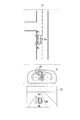
図1に示すように、本実施形態に係る車両は、表示制御装置100と、車両制御装置200と、物体検出装置1と、自車位置検出装置2と、地図取得装置3と、センサ群4と、ウィンカースイッチ5と、を備える。また、表示制御装置100は、コントローラ20と、メータ6と、ディスプレイ7と、ターンシグナル8と、ブレーキランプ9と、ヘッドランプ10とを備える。また、車両制御装置200は、自車状態検出部30と、車両制御ECU31(車両制御コントローラ)と、アクチュエータ32とを備える。本実施形態に係る表示制御装置100は、自動運転と手動運転とを切り替えることが可能な車両に適用される。なお、表示制御装置100は、物体検出装置1と、自車位置検出装置2と、地図取得装置3と、センサ群4と、ウィンカースイッチ5とを含んでもよい。また、以下の説明において、特に断らない限り、乗員は、自車両の乗員を意味する。
(Configuration of display control device)
As shown in FIG. 1, the vehicle according to the present embodiment includes a display control device 100, a vehicle control device 200, an object detection device 1, a vehicle position detection device 2, a map acquisition device 3, and a sensor group 4. And a winker switch 5. Further, the display control device 100 includes a controller 20, a meter 6, a display 7, a turn signal 8, a brake lamp 9, and a headlamp 10. Further, the vehicle control device 200 includes a vehicle state detection unit 30, a vehicle control ECU 31 (vehicle control controller), and an actuator 32. The display control device 100 according to the present embodiment is applied to a vehicle capable of switching between automatic driving and manual driving. The display control device 100 may include an object detection device 1, a vehicle position detection device 2, a map acquisition device 3, a sensor group 4, and a blinker switch 5. Further, in the following description, unless otherwise specified, the occupant means the occupant of the own vehicle.

物体検出装置1は、自車両に搭載された複数の異なる種類の物体検出センサを備える。複数の異なる種類の物体検出センサは、レーザレーダやミリ波レーダ、カメラ、レーザレンジファインダー、車車間通信、路車間通信などである。物体検出装置1は、複数の物体検出センサを用いて自車両の周辺の物体を検出する。より詳しくは、物体検出装置1は、他車両、バイク、自転車、歩行者を含む移動物体、及び駐車車両を含む静止物体を検出する。例えば、物体検出装置1は、移動物体及び静止物体の自車両に対する位置、姿勢(ヨー角)、大きさ、速度、加速度、減速度、ヨーレートを検出する。物体検出装置1は、検出した情報をコントローラ20及び自車状態検出部30に出力する。 The object detection device 1 includes a plurality of different types of object detection sensors mounted on the own vehicle. Multiple different types of object detection sensors include laser radars, millimeter wave radars, cameras, laser rangefinders, vehicle-to-vehicle communication, road-to-vehicle communication, and the like. The object detection device 1 detects an object around the own vehicle by using a plurality of object detection sensors. More specifically, the object detection device 1 detects a moving object including another vehicle, a motorcycle, a bicycle, a pedestrian, and a stationary object including a parked vehicle. For example, the object detection device 1 detects the position, posture (yaw angle), size, speed, acceleration, deceleration, and yaw rate of a moving object and a stationary object with respect to the own vehicle. The object detection device 1 outputs the detected information to the controller 20 and the own vehicle state detection unit 30.

自車位置検出装置2は、自車両に搭載された、GPS(グローバル・ポジショニング・システム)やオドメトリなど自車両の絶対位置を計測する位置検出センサを備える。自車位置検出装置2は、位置検出センサを用いて、自車両の絶対位置、すなわち、所定の基準点に対する自車両の位置や姿勢を検出する。自車位置検出装置2は、検出した情報をコントローラ20及び自車状態検出部30に出力する。 The own vehicle position detection device 2 includes a position detection sensor mounted on the own vehicle that measures the absolute position of the own vehicle such as GPS (Global Positioning System) and odometry. The own vehicle position detecting device 2 detects the absolute position of the own vehicle, that is, the position and the posture of the own vehicle with respect to a predetermined reference point by using the position detection sensor. The own vehicle position detection device 2 outputs the detected information to the controller 20 and the own vehicle state detection unit 30.

地図取得装置3は、自車両が走行する道路の構造を示す地図情報を取得する。地図取得装置3が取得する地図情報には、車線の絶対位置や車線の接続関係、相対位置関係などの道路構造の情報が含まれる。地図取得装置3は、地図情報を格納した地図データベースを所有してもよいし、クラウドコンピューティングにより地図情報を外部の地図データサーバから取得してもよい。また、地図取得装置3は、車車間通信、路車間通信を用いて地図情報を取得してもよい。地図取得装置3は、検出した情報をコントローラ20及び自車状態検出部30に出力する。 The map acquisition device 3 acquires map information indicating the structure of the road on which the own vehicle travels. The map information acquired by the map acquisition device 3 includes road structure information such as absolute lane positions, lane connection relationships, and relative positional relationships. The map acquisition device 3 may own a map database that stores map information, or may acquire map information from an external map data server by cloud computing. Further, the map acquisition device 3 may acquire map information by using vehicle-to-vehicle communication and road-to-vehicle communication. The map acquisition device 3 outputs the detected information to the controller 20 and the own vehicle state detection unit 30.

センサ群4は、自車両の状態を検出する複数のセンサから構成される。センサ群4は、例えば、車速センサ、シフトセンサ、ステアリングセンサなどである。センサ群4は、自車両の車速、シフトポジション、ステアリング角度などを検出し、コントローラ20及び自車状態検出部30に出力する。 The sensor group 4 is composed of a plurality of sensors that detect the state of the own vehicle. The sensor group 4 is, for example, a vehicle speed sensor, a shift sensor, a steering sensor, or the like. The sensor group 4 detects the vehicle speed, shift position, steering angle, etc. of the own vehicle and outputs them to the controller 20 and the own vehicle state detection unit 30.

ウィンカースイッチ5は、運転席付近に設置され、自車両が右左折する際や車線変更する際の旋回方向を検出する。ウィンカースイッチ5は、検出した旋回方向をコントローラ20及び自車状態検出部30に出力する。 The blinker switch 5 is installed near the driver's seat and detects the turning direction when the own vehicle turns left or right or changes lanes. The blinker switch 5 outputs the detected turning direction to the controller 20 and the own vehicle state detection unit 30.

コントローラ20は、物体検出装置1、自車位置検出装置2、地図取得装置3、センサ群4、及びウィンカースイッチ5から情報を取得する。コントローラ20は、取得した情報を用いて、自車両の周辺の状況を示す周辺画像を生成したり、メータ6やディスプレイ7の表示を制御したりする。 The controller 20 acquires information from the object detection device 1, the vehicle position detection device 2, the map acquisition device 3, the sensor group 4, and the blinker switch 5. The controller 20 uses the acquired information to generate a peripheral image showing the situation around the own vehicle, and controls the display of the meter 6 and the display 7.

コントローラ20は、CPU(中央処理装置)、メモリ、及び入出力部を備える汎用のマイクロコンピュータである。マイクロコンピュータには、表示制御装置100として機能させるためのコンピュータプログラムがインストールされている。コンピュータプログラムを実行することにより、マイクロコンピュータは、表示制御装置100が備える複数の情報処理回路として機能する。なお、ここでは、ソフトウェアによって表示制御装置100が備える複数の情報処理回路を実現する例を示すが、もちろん、以下に示す各情報処理を実行するための専用のハードウェアを用意して、情報処理回路を構成することも可能である。また、複数の情報処理回路を個別のハードウェアにより構成してもよい。 The controller 20 is a general-purpose microcomputer including a CPU (central processing unit), a memory, and an input / output unit. A computer program for functioning as the display control device 100 is installed in the microcomputer. By executing the computer program, the microcomputer functions as a plurality of information processing circuits included in the display control device 100. Here, an example of realizing a plurality of information processing circuits included in the display control device 100 by software is shown, but of course, dedicated hardware for executing each of the following information processing is prepared for information processing. It is also possible to configure a circuit. Further, a plurality of information processing circuits may be configured by individual hardware.

コントローラ20は、複数の情報処理回路として、周辺画像生成部21と、周辺状況検出部22と、表示制御部23とを備える。 The controller 20 includes a peripheral image generation unit 21, a peripheral situation detection unit 22, and a display control unit 23 as a plurality of information processing circuits.

周辺画像生成部21は、自車両の周辺の画像に基づき、予め定めた仮想視点、投影面を設定し、自車両の上方から下方(車両の方向)を見たように周辺画像を生成する。なお、周辺画像は、俯瞰画像、鳥瞰画像などでもよく、自車両とその周辺の状況がわかるものであれば画像の形態は問わない。加えて、俯瞰画像、鳥瞰画像の生成方法は既知の技術であるので、詳細な説明を省略する。 The peripheral image generation unit 21 sets a predetermined virtual viewpoint and projection plane based on the image of the periphery of the own vehicle, and generates the peripheral image as if the peripheral image is viewed from above to below (direction of the vehicle) of the own vehicle. The peripheral image may be a bird's-eye view image, a bird's-eye view image, or the like, and the form of the image does not matter as long as the situation of the own vehicle and its surroundings can be understood. In addition, since the method of generating the bird's-eye view image and the bird's-eye view image is a known technique, detailed description thereof will be omitted.

周辺状況検出部22は、自車両の周辺の状況を検出する。自車両の周辺の状況とは、例えば、自車両の周辺に存在する他車両、バイク、自転車、歩行者などの有無である。また、自車両の周辺の状況は、自車両に対する他車両などの相対位置や相対速度なども含む。 The peripheral situation detection unit 22 detects the situation around the own vehicle. The situation around the own vehicle is, for example, the presence or absence of other vehicles, motorcycles, bicycles, pedestrians, etc. existing around the own vehicle. In addition, the situation around the own vehicle includes the relative position and relative speed of other vehicles with respect to the own vehicle.

表示制御部23は、周辺状況検出部22が検出した自車両の周辺の状況に応じて、各種の表示を制御する。表示制御部23は、主として、ターンシグナル8とウィンカーインジケータの表示を制御する。詳細は、後述する。 The display control unit 23 controls various displays according to the surrounding conditions of the own vehicle detected by the peripheral situation detection unit 22. The display control unit 23 mainly controls the display of the turn signal 8 and the blinker indicator. Details will be described later.

メータ6は、例えば、運転席近傍のインストルメントパネルに設置され、乗員に各種情報を表示する装置である。メータ6は、スピードメータ、タコメータ、ウィンカーインジケータなどを備える。なお、メータ6は、後述するディスプレイ7とは異なる液晶ディスプレイで構成されてもよい。なお、本実施形態において、ウィンカーインジケータは、ターンシグナル8の点灯状態を表示するものである。 The meter 6 is, for example, a device installed on an instrument panel near the driver's seat and displaying various information to the occupants. The meter 6 includes a speedometer, a tachometer, a blinker indicator, and the like. The meter 6 may be configured with a liquid crystal display different from the display 7 described later. In this embodiment, the blinker indicator displays the lighting state of the turn signal 8.

ディスプレイ7は、乗員に様々な情報を表示する装置であり、例えば、車室内に設けられるナビゲーション用のディスプレイである。ディスプレイ7は、例えば、自車両の周辺の状況を示す周辺画像を表示する。また、ディスプレイ7は、車両制御ECU31が実行する車両制御の状態を表示する。車両制御には、自動運転、走行支援制御が含まれ、例えば、自動車線変更、自動先行車追越、が含まれる。車両制御の状態には、車両制御が実行されていない状態、準備状態、車両制御が実行されている状態がある。車両制御が実行されている状態では、乗員が車両制御の内容を把握できるように、例えば、車線変更中を示す表示、先行車追越中を示す表示、車線変更における経路の表示、先行車や周囲車両との走行順序を示す表示が、ディスプレイ7に表示される。準備状態は、走行制御を実行する前の状態であり、走行制御がこれから実行されることを示す状態である。準備状態における表示は、例えば、走行制御準備中、これから実行される走行制御の実行内容の表示である。つまり、準備状態における表示は、まだ走行制御が実行されていないにも拘らず、走行制御がこれから実行されることを乗員に把握させるための表示である。 The display 7 is a device that displays various information to the occupants, and is, for example, a navigation display provided in the vehicle interior. The display 7 displays, for example, a peripheral image showing the situation around the own vehicle. In addition, the display 7 displays the state of vehicle control executed by the vehicle control ECU 31. Vehicle control includes automatic driving and driving support control, and includes, for example, lane change and automatic overtaking of preceding vehicles. The vehicle control state includes a state in which vehicle control is not executed, a preparation state, and a state in which vehicle control is executed. In the state where the vehicle control is executed, for example, a display indicating that the lane is being changed, a display indicating that the preceding vehicle is overtaking, a route display in the lane change, a preceding vehicle, and the like so that the occupant can grasp the contents of the vehicle control. A display showing the traveling order with the surrounding vehicles is displayed on the display 7. The ready state is a state before the running control is executed, and is a state indicating that the running control is about to be executed. The display in the preparation state is, for example, a display of the execution contents of the travel control to be executed during the travel control preparation. That is, the display in the ready state is a display for letting the occupant know that the travel control will be executed even though the travel control has not been executed yet.

ターンシグナル8は、自車両の操舵方向を自車両の外部に対し報知する点灯器である。ターンシグナル8は、例えば自車両の前方の左右、後方の左右にそれぞれ設けられる。また、ターンシグナル8は、乗員によるウィンカースイッチ5の操作に応じて点滅点灯する。また、ターンシグナル8は、コントローラ20の制御によっても点滅点灯する。 The turn signal 8 is a lighting device that notifies the outside of the own vehicle of the steering direction of the own vehicle. The turn signals 8 are provided, for example, on the left and right in front of the own vehicle and on the left and right in the rear. Further, the turn signal 8 blinks and lights up in response to the operation of the blinker switch 5 by the occupant. The turn signal 8 also blinks and lights up under the control of the controller 20.

ブレーキランプ9は、自車両の減速を自車両の外部に対し報知する点灯器である。ブレーキランプ9は、例えば自車両の後方の左右にそれぞれ設けられる。また、ブレーキランプ9は、乗員のブレーキ操作やコントローラ20の制御により連続点灯する。ヘッドランプ10は、乗員の視認性を向上させる点灯器である。ヘッドランプ10は、例えば自車両の前方の左右にそれぞれ設けられる。ヘッドランプ10は、乗員の操作により連続点灯する。 The brake lamp 9 is a lighting device that notifies the outside of the own vehicle of the deceleration of the own vehicle. Brake lamps 9 are provided on the left and right rear sides of the own vehicle, for example. Further, the brake lamp 9 is continuously lit by the brake operation of the occupant or the control of the controller 20. The headlamp 10 is a lighting device that improves the visibility of the occupant. Headlamps 10 are provided, for example, on the left and right sides in front of the own vehicle. The headlamp 10 is continuously turned on by the operation of the occupant.

なお、本実施形態において、連続点灯とは、時間的に連続して点灯することを意味する。また、点滅点灯とは、一定の周期で点灯と消灯を繰り返すことを意味する。 In addition, in this embodiment, continuous lighting means lighting continuously in time. Further, blinking lighting means that lighting and extinguishing are repeated at regular intervals.

自車状態検出部30は、自車両の位置、舵角、速度などを検出し、車両制御ECU31に出力する。 The own vehicle state detection unit 30 detects the position, steering angle, speed, etc. of the own vehicle and outputs the output to the vehicle control ECU 31.

車両制御ECU31は、自車状態検出部30や周辺状況検出部22によって検出されたデータに基づいて、周囲状況に合わせた走行経路を算出し、走行経路に基づいて車両制御を実行する。車両制御ECU31は、自車両の駆動・制動、操舵におけるアクチュエータ32の駆動を自動制御する。なお、本実施形態における自動運転とは、例えば、ブレーキ、アクセル、ステアリングなどのアクチュエータの内、少なくとも何れかのアクチュエータを乗員の操作なしに制御している状態のことを指す。そのため、その他のアクチュエータが乗員の操作により作動していたとしても構わない。また、自動運転とは、加減速制御、横位置制御などのいずれかの制御が実行されている状態であればよい。また、本実施形態における手動運転とは、例えば、ブレーキ、アクセル、ステアリングを乗員が操作している状態のことを指す。なお、本実施形態における表示制御装置100は、自動運転と手動運転の両方で適用可能である。なお、以下の記載において、自動運転に係る構成を総称してシステムと表現することがある。 The vehicle control ECU 31 calculates a travel route according to the surrounding conditions based on the data detected by the own vehicle state detection unit 30 and the surrounding condition detection unit 22, and executes vehicle control based on the travel route. The vehicle control ECU 31 automatically controls the drive / braking of the own vehicle and the drive of the actuator 32 in steering. The automatic driving in the present embodiment refers to a state in which at least one of the actuators such as the brake, the accelerator, and the steering is controlled without the operation of the occupant. Therefore, other actuators may be operated by the operation of the occupant. Further, the automatic operation may be a state in which any control such as acceleration / deceleration control or lateral position control is executed. Further, the manual operation in the present embodiment refers to a state in which the occupant is operating the brake, the accelerator, and the steering, for example. The display control device 100 in the present embodiment can be applied to both automatic operation and manual operation. In the following description, the configuration related to automatic operation may be collectively referred to as a system.

(表示制御装置の動作例)
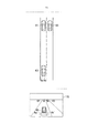
図2A及び2Bを参照して、自動運転による車線変更時の表示制御装置100の動作例について説明する。自動運転による車線変更において、乗員の指示に基づいて車線変更が行われる場合や、システムが乗員に追認を求める場合がある。最初に、乗員の指示に基づく場合について説明する。
(Operation example of display control device)
An operation example of the display control device 100 when changing lanes by automatic driving will be described with reference to FIGS. 2A and 2B. In the lane change by automatic driving, the lane change may be performed based on the occupant's instruction, or the system may ask the occupant for confirmation. First, the case based on the instructions of the occupants will be described.

図2Aに示す周辺画像70は、時刻T1における自車両の周辺の状況を示す。図2Aに示す仮想ターンシグナル8c’,8d’は、ディスプレイ7において、周辺画像70における仮想のターンシグナルを示すものであり、実際のターンシグナル8c,8dとは異なるものである。 The peripheral image 70 shown in FIG. 2A shows the situation around the own vehicle at time T1. The virtual turn signals 8c'and 8d'shown in FIG. 2A show the virtual turn signals in the peripheral image 70 on the display 7, and are different from the actual turn signals 8c and 8d.

図2Aに示すように、時刻T1において、乗員が、自車両60が走行する車線の前方において、自車両60より遅い先行車両61を検出したとする。 As shown in FIG. 2A, it is assumed that at time T1, the occupant detects a preceding vehicle 61 slower than the own vehicle 60 in front of the lane in which the own vehicle 60 travels.

乗員は、先行車両61を追い越すため、ウィンカースイッチ5を右方向に操作して車線変更を指示する。乗員の指示を受けた周辺状況検出部22は、自車両60の周辺の状況を確認し、車線変更可能か否かを判断する。そして、周辺状況検出部22が、車線変更可能と判断した場合に、表示制御部23がターンシグナル8c,8dを点灯して、車両制御ECU31が車線変更を開始する。そして、自車両60が隣接車線に到達した時点で、表示制御部23はターンシグナル8c,8dの点灯を終了する。以下、詳しく説明するために、車線変更に関するタイミングを区別する。 The occupant operates the blinker switch 5 to the right to instruct the lane change in order to overtake the preceding vehicle 61. Upon receiving the instruction from the occupant, the surrounding condition detection unit 22 confirms the surrounding condition of the own vehicle 60 and determines whether or not the lane can be changed. Then, when the peripheral situation detection unit 22 determines that the lane can be changed, the display control unit 23 lights the turn signals 8c and 8d, and the vehicle control ECU 31 starts the lane change. Then, when the own vehicle 60 reaches the adjacent lane, the display control unit 23 ends the lighting of the turn signals 8c and 8d. Hereinafter, for the sake of detailed explanation, the timing of changing lanes will be distinguished.

(1)ターンシグナル準備期間
ターンシグナル準備期間は、乗員がウィンカースイッチ5を右方向に操作してから、表示制御部23がターンシグナル8c,8dを点滅点灯させるまでの期間である。ターンシグナル8c,8dが点滅点灯を開始するタイミングは、周辺状況検出部22が車線変更可能と判断したタイミングである。また、ターンシグナル8c,8dが点滅点灯を開始するタイミングは、周辺状況検出部22が車線変更可能と判断した後であり、かつ自車両60が車線変更を開始する前で、自車両60が車線変更を開始する所定時間前(例えば3秒前)のタイミングでもよい。なお、ターンシグナル8c,8dが点滅点灯を開始するタイミングは、これらに限定されない。ターンシグナル8c,8dが点滅点灯を開始するタイミングは、任意に定めることができる。
(1) Turn signal preparation period The turn signal preparation period is a period from when the occupant operates the blinker switch 5 to the right until the display control unit 23 blinks and lights the turn signals 8c and 8d. The timing at which the turn signals 8c and 8d start blinking and lighting is the timing when the surrounding situation detection unit 22 determines that the lane can be changed. Further, the turn signals 8c and 8d start blinking and lighting after the peripheral situation detection unit 22 determines that the lane can be changed, and before the own vehicle 60 starts the lane change, the own vehicle 60 starts lane change. The timing may be before a predetermined time (for example, 3 seconds) before the start of the change. The timing at which the turn signals 8c and 8d start blinking and lighting is not limited to these. The timing at which the turn signals 8c and 8d start blinking and lighting can be arbitrarily determined.

このターンシグナル準備期間おいて、表示制御部23は、図2Aに示すように、メータ6内のウィンカーインジケータ6bを連続点灯させる。この点灯により、乗員に対し、ターンシグナル8c,8dは点灯していないが、車線変更のために、ターンシグナル8c,8dが点灯準備状態(これから点灯することを示す状態)にあることを示すことができる。これにより、乗員は、自車両60の状態を正確に把握することができる。また、表示制御部23は、ディスプレイ7上で、仮想ターンシグナル8c’,8d’を連続点灯させる。この点灯により、乗員に対し、ターンシグナル8c,8dは点灯していないが、車線変更のために、ターンシグナル8c,8dが点灯準備状態にあることを示すことができる。これにより、乗員は、自車両60の状態を正確に把握することができる。 During this turn signal preparation period, the display control unit 23 continuously lights the blinker indicator 6b in the meter 6 as shown in FIG. 2A. This lighting indicates to the occupants that the turn signals 8c and 8d are not lit, but the turn signals 8c and 8d are in a lighting ready state (a state indicating that they will be lit) due to a lane change. Can be done. As a result, the occupant can accurately grasp the state of the own vehicle 60. Further, the display control unit 23 continuously lights the virtual turn signals 8c'and 8d' on the display 7. By this lighting, it is possible to indicate to the occupant that the turn signals 8c and 8d are not lit, but the turn signals 8c and 8d are ready to be lit due to the lane change. As a result, the occupant can accurately grasp the state of the own vehicle 60.

周辺状況検出部22が車線変更の準備を開始したとき、表示制御部23は、図2Aに示すように、ターンシグナル8c,8dを点灯させない。理由は、周辺状況検出部22が自車両60の周辺の状況を確認し、車線変更を実行するには不適切と判断しているからである。自車両60が車線変更を開始しない、もしくは開始するまでの時間が長いにも関わらず、ターンシグナル8c,8dが点灯すると、自車両60の周辺の他車両に悪影響を与えてしまうおそれがある。例えば、ターンシグナル8c,8dが点灯すると、この点灯を検出した他車両(自動運転車両)は、自車両との車間距離をあけるために急ブレーキを行うことが考えられる。このような急ブレーキにより、他車両の乗員が違和感を感じるおそれがある。そこで、本実施形態では、乗員がウィンカースイッチ5を操作したにも関わらず、少なくとも周辺状況検出部22が車線変更可能と判断するまでは、表示制御部23は、ターンシグナル8c,8dを点灯させない。これにより、表示制御部23は、他車両の乗員が違和感を感じるような挙動(例えば、他車両の急ブレーキ)を抑制することができる。 When the surrounding condition detection unit 22 starts preparing for the lane change, the display control unit 23 does not turn on the turn signals 8c and 8d as shown in FIG. 2A. The reason is that the peripheral situation detection unit 22 confirms the surrounding situation of the own vehicle 60 and determines that it is inappropriate for executing the lane change. If the turn signals 8c and 8d are turned on even though the own vehicle 60 does not start the lane change or it takes a long time to start the lane change, there is a possibility that other vehicles around the own vehicle 60 may be adversely affected. For example, when the turn signals 8c and 8d are turned on, it is conceivable that the other vehicle (autonomous driving vehicle) that detects the lighting may suddenly brake in order to increase the distance from the own vehicle. Due to such sudden braking, the occupants of other vehicles may feel uncomfortable. Therefore, in the present embodiment, the display control unit 23 does not light the turn signals 8c and 8d at least until the peripheral situation detection unit 22 determines that the lane can be changed even though the occupant operates the blinker switch 5. .. As a result, the display control unit 23 can suppress behavior that makes the occupants of the other vehicle feel uncomfortable (for example, sudden braking of the other vehicle).

一方、乗員はウィンカースイッチ5を操作したため、システムが乗員に応答を返さない場合、乗員が不安を感じるおそれがある。そこで、上述したように、表示制御部23は、ウィンカーインジケータ6bを連続点灯させる。また、表示制御部23は、仮想ターンシグナル8c’,8d’も連続点灯させる。これにより、表示制御部23は、車線変更の準備を開始したことを乗員に報知することができる。これにより、乗員は、自身の指示が反映されていることを認識することができ、自車両60の状態を正確に把握することができる。なお、表示制御部23がウィンカーインジケータ6bを連続点灯させる理由は、表示制御部23がウィンカーインジケータ6bを点滅点灯させると、ターンシグナル8c,8dが点灯していないにも拘らず、点灯していると勘違いするおそれがあり、乗員が違和感を感じるおそれがあるからである。一般に、ウィンカーインジケータ6bとターンシグナル8c,8dは、対応した挙動となる。つまり、ウィンカーインジケータ6bが点滅点灯すれば、ターンシグナル8c,8dも点滅点灯する。ウィンカーインジケータ6bが消灯すれば、ターンシグナル8c,8dも消灯する。よって、表示制御部23がウィンカーインジケータ6bを点滅点灯させた場合に、表示制御部23がターンシグナル8c,8dを点灯させないと、乗員は違和感を感じるおそれがある。そこで、本実施形態では、表示制御部23は、ウィンカーインジケータ6bを連続点灯させ、ターンシグナル8c,8dを点灯させない。これにより、表示制御部23は、乗員が乗車中に感じる違和感を抑制することができる。また、表示制御部23は、ターンシグナル8c,8dを点灯させないことにより、自車両60の周辺の他車両に悪影響を与えないようすることができる。 On the other hand, since the occupant operates the blinker switch 5, if the system does not return a response to the occupant, the occupant may feel uneasy. Therefore, as described above, the display control unit 23 continuously lights the blinker indicator 6b. The display control unit 23 also continuously lights the virtual turn signals 8c'and 8d'. As a result, the display control unit 23 can notify the occupants that the preparation for changing lanes has started. As a result, the occupant can recognize that his / her instruction is reflected, and can accurately grasp the state of the own vehicle 60. The reason why the display control unit 23 continuously lights the blinker indicator 6b is that when the display control unit 23 blinks the blinker indicator 6b, the turn signals 8c and 8d are lit even though they are not lit. This is because there is a risk of misunderstanding that the occupant may feel uncomfortable. In general, the blinker indicators 6b and the turn signals 8c and 8d have corresponding behaviors. That is, if the blinker indicator 6b blinks and lights up, the turn signals 8c and 8d also blink and light up. When the blinker indicator 6b goes out, the turn signals 8c and 8d also go out. Therefore, when the display control unit 23 blinks and lights the blinker indicator 6b, if the display control unit 23 does not light the turn signals 8c and 8d, the occupant may feel a sense of discomfort. Therefore, in the present embodiment, the display control unit 23 continuously lights the blinker indicator 6b and does not light the turn signals 8c and 8d. As a result, the display control unit 23 can suppress the discomfort felt by the occupant while riding. Further, the display control unit 23 can prevent the turn signals 8c and 8d from being turned on so as not to adversely affect other vehicles around the own vehicle 60.

また、周辺状況検出部22は、自車両60の周辺の状況を確認し、車線変更可能と判断した場合、表示制御部23は、ウィンカーインジケータ6bを点滅させ、ターンシグナル8c,8dを点滅させる。また、表示制御部23は、仮想ターンシグナル8c’,8d’も点滅させる。これにより、乗員は、ターンシグナル8c,8dが点灯していることを把握することができる。なお、乗員がウィンカースイッチ5を操作したときのウィンカーインジケータ6bの表示形態と、周辺状況検出部22が車線変更可能と判断した場合(自車両60が車線変更を開始する場合や、車線変更の準備状態が終了した場合)のウィンカーインジケータ6bの表示形態は、乗員が自車両60の状態を区別して把握できれば、特に限定されない。つまり上述の説明では、乗員がウィンカースイッチ5を操作したときに表示制御部23がウィンカーインジケータ6bを連続点灯させ、周辺状況検出部22が車線変更可能と判断した場合に表示制御部23がウィンカーインジケータ6bを点滅点灯させたが、必ずしもこれに限られない。 Further, when the peripheral situation detection unit 22 confirms the surrounding situation of the own vehicle 60 and determines that the lane can be changed, the display control unit 23 blinks the blinker indicator 6b and blinks the turn signals 8c and 8d. The display control unit 23 also blinks the virtual turn signals 8c'and 8d'. As a result, the occupant can grasp that the turn signals 8c and 8d are lit. In addition, when the display form of the blinker indicator 6b when the occupant operates the blinker switch 5 and when the surrounding situation detection unit 22 determines that the lane can be changed (when the own vehicle 60 starts the lane change or preparation for the lane change). The display form of the winker indicator 6b (when the state is completed) is not particularly limited as long as the occupant can distinguish and grasp the state of the own vehicle 60. That is, in the above description, when the occupant operates the blinker switch 5, the display control unit 23 continuously lights the blinker indicator 6b, and when the peripheral situation detection unit 22 determines that the lane can be changed, the display control unit 23 indicates the blinker indicator. Although 6b was blinked and lit, it is not necessarily limited to this.

また、本実施形態において、車線変更(走行制御)可能か否かの判断が、切り替わった場合(可能から不可能や、不可能から可能)、表示制御部23は、ウィンカーインジケータ6bの表示形態を切り替えて、ターンシグナル準備期間の表示形態と、ターンシグナル準備期間が終了した後の表示形態とを区別して表示する。これにより、乗員は、ターンシグナル準備期間が終了したタイミングで、ターンシグナル準備期間が終了したことを把握することができるようになる。 Further, in the present embodiment, when the determination as to whether or not the lane change (travel control) is possible is switched (possible to impossible or impossible), the display control unit 23 changes the display mode of the blinker indicator 6b. By switching, the display form of the turn signal preparation period and the display form after the end of the turn signal preparation period are displayed separately. As a result, the occupant can know that the turn signal preparation period has ended at the timing when the turn signal preparation period has ended.

次に、車線変更可能か否かの判断について説明する。周辺状況検出部22は、車線変更の妨げとなるような他車両がいる場合、車線変更はできないと判断する。例えば、周辺状況検出部22は、車線変更後の走行車線(以下、隣接車線という)において、自車両60に接近してくる後続車両がいる場合、車線変更はできないと判断する。つまり、周辺状況検出部22は、隣接車線において、自車両60に接近してくる後続車両がいる場合、車線変更が不可能と判断する。一方、周辺状況検出部22は、自車両60の周辺において、車線変更の妨げとなるような他車両がいない場合、車線変更が可能であり、所定時間後に車線変更制御を実行すると判断する。つまり、周辺状況検出部22は、自車両60の周辺において、車線変更の妨げとなるような他車両がいない場合、車線変更は可能であると判断する。 Next, the determination of whether or not the lane can be changed will be described. The surrounding situation detection unit 22 determines that the lane cannot be changed when there is another vehicle that hinders the lane change. For example, the surrounding situation detection unit 22 determines that the lane cannot be changed when there is a following vehicle approaching the own vehicle 60 in the traveling lane after the lane change (hereinafter referred to as an adjacent lane). That is, the surrounding situation detection unit 22 determines that it is impossible to change lanes when there is a following vehicle approaching the own vehicle 60 in the adjacent lane. On the other hand, the peripheral situation detection unit 22 determines that the lane change is possible and the lane change control is executed after a predetermined time when there is no other vehicle in the vicinity of the own vehicle 60 that hinders the lane change. That is, the peripheral situation detection unit 22 determines that the lane change is possible when there is no other vehicle in the vicinity of the own vehicle 60 that hinders the lane change.

(2)車両制御準備期間
時間が進み、図2Bに示す時刻T2において、周辺状況検出部22が、車線変更が可能であり、所定時間後に車両制御ECU31が車線変更制御を実行すると判断した場合、つまり、車両制御ECU31が車線変更制御を開始する所定時間前(例えば、3秒前)に、表示制御部23は、ウィンカーインジケータ6bの点灯状態を、連続点灯から点滅点灯に切り替える。換言すれば、車両制御ECU31が所定時間後に車線変更を行う場合、表示制御部23は、ウィンカーインジケータ6bの点灯状態を、連続点灯から点滅点灯に切り替える。また、表示制御部23は、ウィンカーインジケータ6bの点灯状態に対応するように、ターンシグナル8c,8dの点灯状態を、消灯から点滅点灯に切り替える。また、表示制御部23は、ターンシグナル8c,8dの点灯状態に対応するように、仮想ターンシグナル8c’,8d’の点灯状態を、連続点灯から点滅点灯に切り替える。これにより、表示制御部23は、乗員に対し、もなく車線変更することを報知することができる。また、表示制御部23は、ターンシグナル8c,8dを点滅点灯させることにより、自車両60の周辺の他車両に対し、所定時間後に車線変更することを報知することができる。これにより、表示制御部23は、他車両の乗員に対し、自車両60が車線変更制御を開始する手前から、自車両60が車線変更することを報知することができる。これにより、他車両は、事前に減速して車間距離をあけるなどの他車両の乗員が違和感を感じる挙動を抑制することができる。なお、所定時間は、ターンシグナル8c,8dが点滅点灯してから車線変更制御を開始するまでの時間であり、特に限定されないが、例えば3秒である。また、所定時間は、法律や一般的なルールで定められている場合は、予めその時間が設定されてもよい。
(2) Vehicle control preparation period When the time advances and at time T2 shown in FIG. 2B, the peripheral situation detection unit 22 determines that the lane can be changed and the vehicle control ECU 31 executes the lane change control after a predetermined time. That is, before a predetermined time (for example, 3 seconds before) when the vehicle control ECU 31 starts the lane change control, the display control unit 23 switches the lighting state of the blinker indicator 6b from continuous lighting to blinking lighting. In other words, when the vehicle control ECU 31 changes lanes after a predetermined time, the display control unit 23 switches the lighting state of the blinker indicator 6b from continuous lighting to blinking lighting. Further, the display control unit 23 switches the lighting state of the turn signals 8c and 8d from extinguished to blinking so as to correspond to the lighting state of the blinker indicator 6b. Further, the display control unit 23 switches the lighting state of the virtual turn signals 8c'and 8d' from continuous lighting to blinking lighting so as to correspond to the lighting states of the turn signals 8c and 8d. As a result, the display control unit 23 can notify the occupant of the change of lane. Further, the display control unit 23 can notify other vehicles around the own vehicle 60 that the lane is changed after a predetermined time by blinking and lighting the turn signals 8c and 8d. As a result, the display control unit 23 can notify the occupants of the other vehicle that the own vehicle 60 will change lanes before the own vehicle 60 starts the lane change control. As a result, the other vehicle can suppress the behavior that the occupants of the other vehicle feel uncomfortable, such as decelerating in advance to increase the inter-vehicle distance. The predetermined time is the time from when the turn signals 8c and 8d blink and turn on until the lane change control is started, and is not particularly limited, but is, for example, 3 seconds. Further, the predetermined time may be set in advance if it is stipulated by law or general rules.

なお、周辺状況検出部22が、車線変更が可能であると判断した場合、実際に車両制御ECU31が車両制御を実行するまで、ディスプレイ7が、車両制御(自動車線変更)の準備状態を表示するようにしてもよい。これにより、まだ走行制御が実行されていないにも拘らず、乗員は走行制御がこれから実行されることを把握することができるようになる。 When the peripheral situation detection unit 22 determines that the lane can be changed, the display 7 displays the preparation status for the vehicle control (lane change) until the vehicle control ECU 31 actually executes the vehicle control. You may do so. As a result, the occupant can know that the driving control will be executed even though the traveling control has not been executed yet.

また、表示制御部23は、ターンシグナル8c,8dの点灯開始タイミングと、ウィンカーインジケータ6bの点灯開始タイミングと、ディスプレイ7における準備状態の表示の点灯開始タイミングとを異ならせる。これにより、乗員は、ターンシグナル8c,8dの点灯状況や、ターンシグナル8c,8dがこれから点灯するのか、車両制御がこれから実行されるのか、を把握することができるようになるため、乗員は自車両60の状態を正確に把握することができるようになる。したがって、表示制御部23は、乗員が乗車中に感じる違和感を抑制することができる。 Further, the display control unit 23 makes the lighting start timing of the turn signals 8c and 8d different from the lighting start timing of the blinker indicator 6b and the lighting start timing of the display of the ready state on the display 7. As a result, the occupant can grasp the lighting status of the turn signals 8c and 8d, whether the turn signals 8c and 8d are to be lit, and whether the vehicle control is to be executed. The state of the vehicle 60 can be accurately grasped. Therefore, the display control unit 23 can suppress the discomfort felt by the occupant while riding.

(3)車両制御実行期間
時間が進み、車両制御ECU31が車線変更制御を実行する場合、つまり、車線変更準備期間に入って、上述した所定時間が経過した場合、表示制御部23は、ウィンカーインジケータ6bの点灯状態を継続する。また、表示制御部23は、ウィンカーインジケータ6bの点灯状態に対応するように、ターンシグナル8c,8dの点灯状態を継続する。また、表示制御部23は、ターンシグナル8c,8dの点灯状態に対応するように、仮想ターンシグナル8c’,8d’の点灯状態を継続する。これにより、表示制御部23は、車線変更していることを報知することができる。また、表示制御部23は、ターンシグナル8c,8dを点滅点灯させることにより、自車両60の周辺の他車両に対し、車線変更していることを報知することができる。これにより、表示制御部23は、他車両の乗員に対し、自車両60が車線変更制御している時、自車両60が車線変更することを報知することができる。これにより、他車両は、事前に減速して車間距離をあけるなどの他車両の乗員が違和感を感じる挙動を抑制することができる。そして、隣接車線への車線変更が終了した時点で、表示制御部23は、ウィンカーインジケータ6b、ターンシグナル8c,8d、仮想ターンシグナル8c’,8d’の点灯状態を終了して消灯する。
(3) Vehicle control execution period When the time advances and the vehicle control ECU 31 executes the lane change control, that is, when the above-mentioned predetermined time elapses after entering the lane change preparation period, the display control unit 23 displays the blinker indicator. The lighting state of 6b is continued. Further, the display control unit 23 continues the lighting state of the turn signals 8c and 8d so as to correspond to the lighting state of the blinker indicator 6b. Further, the display control unit 23 keeps the lighting states of the virtual turn signals 8c'and 8d' corresponding to the lighting states of the turn signals 8c and 8d. As a result, the display control unit 23 can notify that the lane is being changed. In addition, the display control unit 23 can notify other vehicles around the own vehicle 60 that the lane is being changed by blinking and lighting the turn signals 8c and 8d. As a result, the display control unit 23 can notify the occupants of the other vehicle that the own vehicle 60 will change lanes when the own vehicle 60 is controlling the lane change. As a result, the other vehicle can suppress the behavior that the occupants of the other vehicle feel uncomfortable, such as decelerating in advance to increase the inter-vehicle distance. Then, when the lane change to the adjacent lane is completed, the display control unit 23 ends the lighting state of the blinker indicators 6b, the turn signals 8c and 8d, and the virtual turn signals 8c'and 8d'and turns off the lights.

また、ディスプレイ7が、車両制御(自動車線変更)が実行されている状態を表示するようにしてもよい。これにより、乗員は車両制御が実行されていることを把握することができるようになる。 Further, the display 7 may display a state in which vehicle control (changing lanes) is being executed. As a result, the occupant can know that the vehicle control is being executed.

なお、車両制御準備期間と車両制御実行期間との間で、表示制御部23は、ウィンカーインジケータ6b、仮想ターンシグナル8c’,8d’の表示形態(例えば、点滅の周期、点滅の光の強度や色)を切り替えるようにしてもよい。これにより、乗員は、車両制御が実行されていることを正確に把握することができる。また、表示制御部23がターンシグナル8c,8dの表示形態を切り替えることにより、他車両の乗員も、車両制御が実行されていることを把握することができるようになる。なお、車両制御準備期間と車両制御実行期間との間での、ウィンカーインジケータ6b、ターンシグナル8c,8d、及び仮想ターンシグナル8c’,8d’の表示形態の切り替えは、自車両60が自動運転を実行している間にのみ、実施されてもよい。これにより、乗員は、自動運転による車両制御が実行されていることを正確に把握することができる。それに加え、他車両の乗員も、ターンシグナル8c,8dの点滅の仕方が通常と違うため、通常の走行と違うことや、例えば、自動運転が実行されていることを把握できるようになる。 Between the vehicle control preparation period and the vehicle control execution period, the display control unit 23 displays the display modes of the blinker indicator 6b and the virtual turn signals 8c'and 8d' (for example, the blinking cycle, the intensity of the blinking light, and the like. Color) may be switched. As a result, the occupant can accurately grasp that the vehicle control is being executed. Further, when the display control unit 23 switches the display form of the turn signals 8c and 8d, the occupants of other vehicles can also grasp that the vehicle control is being executed. It should be noted that the own vehicle 60 automatically drives the switching of the display modes of the blinker indicators 6b, the turn signals 8c and 8d, and the virtual turn signals 8c'and 8d' between the vehicle control preparation period and the vehicle control execution period. It may be carried out only while it is running. As a result, the occupant can accurately grasp that the vehicle control by the automatic driving is executed. In addition, the occupants of other vehicles will be able to understand that the turn signals 8c and 8d are blinking differently from normal driving, and that, for example, automatic driving is being executed.

以上説明したように、表示制御部23は、システムが車線変更を行う際に、ターンシグナル8c,8dの点灯開始タイミングと、ウィンカーインジケータ6bの点灯開始タイミングを異ならせる。つまり、周辺状況検出部22が車線変更の準備を行っている間は、表示制御部23は、ウィンカーインジケータ6bを連続点灯させるが、ターンシグナル8c,8dを点灯させない。つまり、表示制御部23は、ターンシグナル8c,8dより先にウィンカーインジケータ6bを点灯させる。 As described above, the display control unit 23 makes the lighting start timings of the turn signals 8c and 8d different from the lighting start timings of the blinker indicators 6b when the system changes lanes. That is, while the surrounding situation detection unit 22 is preparing to change lanes, the display control unit 23 continuously lights the blinker indicators 6b, but does not turn on the turn signals 8c and 8d. That is, the display control unit 23 turns on the blinker indicator 6b before the turn signals 8c and 8d.

その後、周辺状況検出部22が車線変更の準備は完了したと判断した場合、表示制御部23は、ウィンカーインジケータ6bの点灯状態を、連続点灯から点滅点灯に切り替える。また、表示制御部23は、ウィンカーインジケータ6bの点灯状態に対応するように、ターンシグナル8c,8dの点灯状態を、消灯から点滅点灯に切り替える。 After that, when the peripheral situation detection unit 22 determines that the preparation for changing lanes is completed, the display control unit 23 switches the lighting state of the blinker indicator 6b from continuous lighting to blinking lighting. Further, the display control unit 23 switches the lighting state of the turn signals 8c and 8d from extinguished to blinking so as to correspond to the lighting state of the blinker indicator 6b.

このような点灯制御により、表示制御部23は、乗員が乗車中に感じる違和感を抑制することができる。すなわち、乗員がウィンカースイッチ5を操作した時に、表示制御部23は、ウィンカーインジケータ6bを連続点灯させることにより、乗員は、自身の指示が反映されていることを認識することができ、自車両60の状態を正確に把握することができる。また、ターンシグナル準備期間が終了した場合、表示制御部23は、ウィンカーインジケータ6b及びターンシグナル8c,8dを点滅点灯させることにより、乗員は、まもなく車線変更することを知ることができる。 By such lighting control, the display control unit 23 can suppress a feeling of strangeness that the occupant feels while riding. That is, when the occupant operates the blinker switch 5, the display control unit 23 continuously lights the blinker indicator 6b so that the occupant can recognize that his / her instruction is reflected and the own vehicle 60. Can accurately grasp the state of. Further, when the turn signal preparation period is completed, the display control unit 23 blinks and lights the blinker indicators 6b and the turn signals 8c and 8d so that the occupant can know that the lane will be changed soon.

上述した動作例は、乗員の1回の指示にしたがって、システムが車線変更を行う場合の動作例である。自動運転では、乗員の2回の指示にしたがって、システムが車線変更を行う場合もある。以下、乗員の2回の指示による動作例について説明する。 The above-mentioned operation example is an operation example when the system changes lanes according to one instruction of the occupant. In autonomous driving, the system may change lanes according to the occupant's two instructions. Hereinafter, an operation example in which the occupant is instructed twice will be described.

(1)ターンシグナル準備期間
図2Aに示すように、時刻T1において、乗員が、自車両60が走行する車線の前方において、自車両60より遅い先行車両61を検出したとする。
(1) Turn signal preparation period As shown in FIG. 2A, it is assumed that at time T1, the occupant detects a preceding vehicle 61 slower than the own vehicle 60 in front of the lane in which the own vehicle 60 travels.

乗員は、先行車両61を追い越すため、ウィンカースイッチ5を右方向に操作して車線変更を指示する。これを乗員の1回目の指示とよぶ。1回目の指示を受けた後、表示制御部23がターンシグナル8c,8dを点滅点灯させるまでの期間をターンシグナル準備期間とする。ターンシグナル8c,8dが点滅点灯を開始するタイミングは、周辺状況検出部22が車線変更可能と判断したタイミングである。また、ターンシグナル8c,8dが点滅点灯を開始するタイミングは、周辺状況検出部22が車線変更可能と判断した後であり、かつ自車両60が車線変更を開始する前で、自車両60が車線変更を開始する所定時間前(例えば3秒前)のタイミングでもよい。なお、ターンシグナル8c,8dが点滅点灯を開始するタイミングは、これらに限定されない。ターンシグナル8c,8dが点滅点灯を開始するタイミングは、任意に定めることができる。このとき、表示制御部23は、図2Aに示すように、ウィンカーインジケータ6bを連続点灯させる。また、表示制御部23は、仮想ターンシグナル8c’,8d’を連続点灯させる。これにより、乗員は、システムが車線変更の準備を開始したことを認識することができ、自車両60の状態を正確に把握することができる。上述したターンシグナル準備期間の点灯方法は、乗員の1回の指示にしたがって、システムが車線変更を行う場合と同じである。 The occupant operates the blinker switch 5 to the right to instruct the lane change in order to overtake the preceding vehicle 61. This is called the occupant's first instruction. The period until the display control unit 23 blinks and lights the turn signals 8c and 8d after receiving the first instruction is set as the turn signal preparation period. The timing at which the turn signals 8c and 8d start blinking and lighting is the timing when the surrounding situation detection unit 22 determines that the lane can be changed. Further, the turn signals 8c and 8d start blinking and lighting after the peripheral situation detection unit 22 determines that the lane can be changed, and before the own vehicle 60 starts the lane change, the own vehicle 60 starts lane change. The timing may be before a predetermined time (for example, 3 seconds) before the start of the change. The timing at which the turn signals 8c and 8d start blinking and lighting is not limited to these. The timing at which the turn signals 8c and 8d start blinking and lighting can be arbitrarily determined. At this time, the display control unit 23 continuously lights the blinker indicator 6b as shown in FIG. 2A. Further, the display control unit 23 continuously lights the virtual turn signals 8c'and 8d'. As a result, the occupant can recognize that the system has started preparing for the lane change, and can accurately grasp the state of the own vehicle 60. The lighting method of the turn signal preparation period described above is the same as when the system changes lanes according to one instruction of the occupant.

(2)車両制御準備期間
時間が進み、図2Bに示す時刻T2において、周辺状況検出部22が、所定時間後に車線変更は可能であると判断した場合、つまり、車両制御ECU31が車線変更制御を開始する所定時間前(例えば、3秒前)に、システムは、乗員に対し車線変更の準備が完了したことを報知する。例えば、システムは、スピーカを介して、「車線変更の準備が完了しました。ウィンカースイッチを右方向にオンして下さい。」と乗員に2回目の指示を求める。乗員は、この通知を受ける前から、システムが車線変更の準備を開始していることを知っているため、この通知を受けても違和感を感じない。この通知を受けて乗員は、ウィンカースイッチ5をオンする。これを乗員の2回目の指示とよぶ。2回目の指示を受けた表示制御部23は、ウィンカーインジケータ6bの点灯状態を、連続点灯から点滅点灯に切り替える。また、表示制御部23は、ウィンカーインジケータ6bの点灯状態に対応するように、ターンシグナル8c,8dの点灯状態を、消灯から点滅点灯に切り替える。また、表示制御部23は、ターンシグナル8c,8dの点灯状態に対応するように、仮想ターンシグナル8c’,8d’の点灯状態を、連続点灯から点滅点灯に切り替える。これにより、表示制御部23は、乗員に対し、まもなく車線変更することを報知することができる。また、表示制御部23は、ターンシグナル8c,8dを点滅点灯させることにより、自車両60の周辺の他車両に対し、所定時間後に車線変更することを報知することができる。これにより、表示制御部23は、他車両の乗員に対し、自車両60が車線変更制御を開始する手前から、自車両60が車線変更することを報知することができる。これにより、他車両は、事前に減速して車間距離をあけるなどの他車両の乗員が違和感を感じるような挙動を抑制することができる。上述した車両制御準備期間の点灯方法は、乗員の1回の指示にしたがって、システムが車線変更を行う場合と同じである。
(2) Vehicle control preparation period When the time advances and the surrounding situation detection unit 22 determines that the lane change is possible after a predetermined time at the time T2 shown in FIG. 2B, that is, the vehicle control ECU 31 controls the lane change. A predetermined time before the start (eg, 3 seconds), the system notifies the occupants that they are ready to change lanes. For example, the system asks the occupant for a second instruction via a speaker, "You are ready to change lanes. Turn on the blinker switch to the right." The occupants know that the system is preparing to change lanes before receiving this notification, so they will not feel uncomfortable when receiving this notification. Upon receiving this notification, the occupant turns on the blinker switch 5. This is called the occupant's second instruction. Upon receiving the second instruction, the display control unit 23 switches the lighting state of the blinker indicator 6b from continuous lighting to blinking lighting. Further, the display control unit 23 switches the lighting state of the turn signals 8c and 8d from extinguished to blinking so as to correspond to the lighting state of the blinker indicator 6b. Further, the display control unit 23 switches the lighting state of the virtual turn signals 8c'and 8d' from continuous lighting to blinking lighting so as to correspond to the lighting states of the turn signals 8c and 8d. As a result, the display control unit 23 can notify the occupant that the lane will be changed soon. Further, the display control unit 23 can notify other vehicles around the own vehicle 60 that the lane is changed after a predetermined time by blinking and lighting the turn signals 8c and 8d. As a result, the display control unit 23 can notify the occupants of the other vehicle that the own vehicle 60 will change lanes before the own vehicle 60 starts the lane change control. As a result, the other vehicle can suppress the behavior that the occupants of the other vehicle feel uncomfortable, such as decelerating in advance to increase the inter-vehicle distance. The lighting method of the vehicle control preparation period described above is the same as the case where the system changes lanes according to one instruction of the occupant.

(3)車両制御実行期間
時間が進み、車両制御ECU31が車線変更制御を実行する場合、つまり、車線変更準備期間に入って、上述した所定時間が経過した場合、表示制御部23は、ウィンカーインジケータ6bの点灯状態を継続する。また、表示制御部23は、ウィンカーインジケータ6bの点灯状態に対応するように、ターンシグナル8c,8dの点灯状態を継続する。また、表示制御部23は、ターンシグナル8c,8dの点灯状態に対応するように、仮想ターンシグナル8c’,8d’の点灯状態を継続する。これにより、表示制御部23は、車線変更していることを報知することができる。また、表示制御部23は、ターンシグナル8c,8dを点滅点灯させることにより、自車両60の周辺の他車両に対し、車線変更していることを報知することができる。これにより、表示制御部23は、他車両の乗員に対し、自車両60が車線変更制御している時、自車両60が車線変更することを報知することができる。上述した車両制御実行期間の点灯方法は、乗員の1回の指示にしたがって、システムが車線変更を行う場合と同じである。
(3) Vehicle control execution period When the time advances and the vehicle control ECU 31 executes the lane change control, that is, when the above-mentioned predetermined time elapses after entering the lane change preparation period, the display control unit 23 displays the blinker indicator. The lighting state of 6b is continued. Further, the display control unit 23 continues the lighting state of the turn signals 8c and 8d so as to correspond to the lighting state of the blinker indicator 6b. Further, the display control unit 23 keeps the lighting states of the virtual turn signals 8c'and 8d' corresponding to the lighting states of the turn signals 8c and 8d. As a result, the display control unit 23 can notify that the lane is being changed. In addition, the display control unit 23 can notify other vehicles around the own vehicle 60 that the lane is being changed by blinking and lighting the turn signals 8c and 8d. As a result, the display control unit 23 can notify the occupants of the other vehicle that the own vehicle 60 will change lanes when the own vehicle 60 is controlling the lane change. The lighting method during the vehicle control execution period described above is the same as when the system changes lanes according to one instruction from the occupant.

なお、乗員の1回目の指示の後に、周辺状況検出部22が周辺の状況を確認したが、これに限定されない。乗員の1回目の指示の後に、乗員が周辺の状況を確認し、2回目の指示を行ってもよい。また、乗員の1回目の指示も2回目の指示も、ウィンカースイッチ5の操作に限定されない。乗員の1回目の指示及び2回目の指示は、他のスイッチでもよく、音声入力でもよい。 After the first instruction by the occupant, the peripheral situation detection unit 22 confirmed the surrounding situation, but the present invention is not limited to this. After the first instruction of the occupant, the occupant may confirm the surrounding situation and give the second instruction. Further, neither the first instruction nor the second instruction of the occupant is limited to the operation of the blinker switch 5. The first and second instructions of the occupant may be other switches or voice input.

上述した動作例は、乗員の1回の指示または2回の指示にしたがって、システムが車線変更を行う場合の動作例である。自動運転では、システムの判断を乗員に追認してもらうことで、システムが車線変更を行う場合もある。以下、システムが乗員に追認を求める場合の動作例について説明する。なお、乗員の追認も指示の一種である。 The above-mentioned operation example is an operation example when the system changes lanes according to one instruction or two instructions of the occupant. In autonomous driving, the system may change lanes by having the occupants confirm the judgment of the system. The operation example when the system asks the occupant for confirmation will be described below. Confirmation of the occupants is also a kind of instruction.

(1)ターンシグナル準備期間
図2Aに示すように、時刻T1において、周辺状況検出部22が、自車両60が走行する車線の前方において、自車両60より遅い先行車両61を検出したとする。表示制御部23は、システムが車線変更は可能であることを乗員に伝えるため、ウィンカーインジケータ6bを連続点灯させる。仮想ターンシグナル8c’,8d’を連続点灯させる。これにより、乗員は、システムが車線変更は可能である状況を認識していることを把握することができ、自車両60の状態を正確に把握することができる。上述したターンシグナル準備期間の点灯方法は、乗員の1回の指示にしたがって、システムが車線変更を行う場合と同じである。
(1) Turn signal preparation period As shown in FIG. 2A, it is assumed that at time T1, the peripheral situation detection unit 22 detects a preceding vehicle 61 slower than the own vehicle 60 in front of the lane in which the own vehicle 60 travels. The display control unit 23 continuously lights the blinker indicator 6b in order to inform the occupants that the system can change lanes. The virtual turn signals 8c'and 8d' are continuously lit. As a result, the occupant can grasp that the system recognizes the situation where the lane can be changed, and can accurately grasp the state of the own vehicle 60. The lighting method of the turn signal preparation period described above is the same as when the system changes lanes according to one instruction of the occupant.

(2)車両制御準備期間
時間が進み、図2Bに示す時刻T2において、周辺状況検出部22が、所定時間後に車線変更は可能であると判断した場合、システムは、乗員に対し車線変更の準備が完了したことを報知する。例えば、システムは、スピーカを介して、「車線変更の準備が完了しました。ウィンカースイッチを右方向にオンして下さい。」と乗員に追認を求める。乗員は、この通知を受け取る前から、システムが車線変更の準備を開始していることを知っているため、この通知を受けても違和感を感じない。乗員が、ウィンカースイッチ5をオンすると、表示制御部23は、ウィンカーインジケータ6bの点灯状態を、連続点灯から点滅点灯に切り替える。また、表示制御部23は、ウィンカーインジケータ6bの点灯状態に対応するように、ターンシグナル8c,8dの点灯状態を、消灯から点滅点灯に切り替える。また、表示制御部23は、ターンシグナル8c,8dの点灯状態に対応するように、仮想ターンシグナル8c’,8d’の点灯状態を、連続点灯から点滅点灯に切り替える。これにより、表示制御部23は、乗員に対し、まもなく車線変更することを報知することができる。また、表示制御部23は、ターンシグナル8c,8dを点滅点灯させることにより、自車両60の周辺の他車両に対し、所定時間後に車線変更することを報知することができる。これにより、表示制御部23は、他車両の乗員に対し、自車両60が車線変更制御を開始する手前から、自車両60が車線変更することを報知することができる。これにより、他車両は、事前に減速して車間距離をあけるなどの他車両の乗員が違和感を感じるような挙動を抑制することができる。なお、車両制御準備期間は、乗員がウィンカースイッチ5をオンするまでとしてもよく、車両制御ECU31が車両制御を開始するまでとしてもよい。上述した車両制御準備期間の点灯方法は、乗員の1回の指示にしたがって、システムが車線変更を行う場合と同じである。
(2) Vehicle control preparation period When the time advances and the surrounding situation detection unit 22 determines that the lane change is possible after a predetermined time at the time T2 shown in FIG. 2B, the system prepares the occupant for the lane change. Notifies that is completed. For example, the system asks the occupants for confirmation through the speaker, "You are ready to change lanes. Turn on the blinker switch to the right." The occupants know that the system is preparing to change lanes before receiving this notification, so they will not feel uncomfortable with this notification. When the occupant turns on the blinker switch 5, the display control unit 23 switches the lighting state of the blinker indicator 6b from continuous lighting to blinking lighting. Further, the display control unit 23 switches the lighting state of the turn signals 8c and 8d from extinguished to blinking so as to correspond to the lighting state of the blinker indicator 6b. Further, the display control unit 23 switches the lighting state of the virtual turn signals 8c'and 8d' from continuous lighting to blinking lighting so as to correspond to the lighting states of the turn signals 8c and 8d. As a result, the display control unit 23 can notify the occupant that the lane will be changed soon. Further, the display control unit 23 can notify other vehicles around the own vehicle 60 that the lane is changed after a predetermined time by blinking and lighting the turn signals 8c and 8d. As a result, the display control unit 23 can notify the occupants of the other vehicle that the own vehicle 60 will change lanes before the own vehicle 60 starts the lane change control. As a result, the other vehicle can suppress the behavior that the occupants of the other vehicle feel uncomfortable, such as decelerating in advance to increase the inter-vehicle distance. The vehicle control preparation period may be until the occupant turns on the blinker switch 5, or until the vehicle control ECU 31 starts vehicle control. The lighting method of the vehicle control preparation period described above is the same as the case where the system changes lanes according to one instruction of the occupant.

(3)車両制御実行期間
時間が進み、車両制御ECU31が車線変更制御を実行する場合、つまり、車線変更準備期間に入って、上述した所定時間が経過した場合、表示制御部23は、ウィンカーインジケータ6bの点灯状態を継続する。また、表示制御部23は、ウィンカーインジケータ6bの点灯状態に対応するように、ターンシグナル8c,8dの点灯状態を継続する。また、表示制御部23は、ターンシグナル8c,8dの点灯状態に対応するように、仮想ターンシグナル8c’,8d’の点灯状態を継続する。これにより、表示制御部23は、車線変更していることを報知することができる。また、表示制御部23は、ターンシグナル8c,8dを点滅点灯させることにより、自車両60の周辺の他車両に対し、車線変更していることを報知することができる。これにより、表示制御部23は、他車両の乗員に対し、自車両60が車線変更制御している時、自車両60が車線変更することを報知することができる。上述した車両制御実行期間の点灯方法は、乗員の1回の指示にしたがって、システムが車線変更を行う場合と同じである。
(3) Vehicle control execution period When the time advances and the vehicle control ECU 31 executes the lane change control, that is, when the above-mentioned predetermined time elapses after entering the lane change preparation period, the display control unit 23 displays the blinker indicator. The lighting state of 6b is continued. Further, the display control unit 23 continues the lighting state of the turn signals 8c and 8d so as to correspond to the lighting state of the blinker indicator 6b. Further, the display control unit 23 keeps the lighting states of the virtual turn signals 8c'and 8d' corresponding to the lighting states of the turn signals 8c and 8d. As a result, the display control unit 23 can notify that the lane is being changed. In addition, the display control unit 23 can notify other vehicles around the own vehicle 60 that the lane is being changed by blinking and lighting the turn signals 8c and 8d. As a result, the display control unit 23 can notify the occupants of the other vehicle that the own vehicle 60 will change lanes when the own vehicle 60 is controlling the lane change. The lighting method during the vehicle control execution period described above is the same as when the system changes lanes according to one instruction from the occupant.

次に、図3A及び3Bを参照して、自動運転による左折時の表示制御装置100の動作例について説明する。なお、図3A以降においては、乗員の1回の指示にしたがって、自動制御する例について説明する。乗員の2回の指示や乗員の追認による動作例については省略するが、図3A以降の動作例において、乗員の2回の指示や乗員の追認による自動運転は、もちろん適用可能である。 Next, an operation example of the display control device 100 at the time of turning left by automatic operation will be described with reference to FIGS. 3A and 3B. In addition, in FIG. 3A and later, an example of automatic control according to one instruction of the occupant will be described. Although the operation example by the occupant's two instructions and the occupant's confirmation is omitted, in the operation examples after FIG. 3A, the occupant's two instructions and the automatic operation by the occupant's confirmation are of course applicable.

図3Aに示すように、時刻T1において、乗員は、交差点で左折するため、ウィンカースイッチ5を左方向に操作して左折を指示する。乗員の指示を受けた周辺状況検出部22は、左折を行うための準備を開始する。例えば、周辺状況検出部22は、自車両60の周辺の状況を確認し、左折可能か否かを判断する。周辺状況検出部22が左折の準備を開始したとき、表示制御部23は、図3Aに示すように、ウィンカーインジケータ6aを連続点灯させる。また、表示制御部23は、仮想ターンシグナル8a’,8b’を連続点灯させる。これにより、乗員は、システムが左折の準備を開始したことを認識することができ、自車両60の状態を正確に把握することができる。周辺状況検出部22が左折の準備を開始したとき、表示制御部23は、図3Aに示すように、ターンシグナル8aを点灯させない。左折の準備が完了していないからである。 As shown in FIG. 3A, at time T1, the occupant operates the blinker switch 5 to the left to instruct a left turn in order to turn left at the intersection. Upon receiving the instruction from the occupant, the surrounding condition detection unit 22 starts preparations for making a left turn. For example, the peripheral situation detection unit 22 confirms the surrounding situation of the own vehicle 60 and determines whether or not it is possible to turn left. When the peripheral situation detection unit 22 starts preparing for a left turn, the display control unit 23 continuously lights the blinker indicator 6a as shown in FIG. 3A. Further, the display control unit 23 continuously lights the virtual turn signals 8a'and 8b'. As a result, the occupant can recognize that the system has started preparing for the left turn, and can accurately grasp the state of the own vehicle 60. When the peripheral situation detection unit 22 starts preparing for a left turn, the display control unit 23 does not turn on the turn signal 8a as shown in FIG. 3A. This is because preparations for a left turn are not complete.

時間が進み、図3Bに示す時刻T2において、周辺状況検出部22が、所定時間後に左折は可能であると判断した場合、表示制御部23は、ウィンカーインジケータ6aの点灯状態を、連続点灯から点滅点灯に切り替える。また、表示制御部23は、ウィンカーインジケータ6aの点灯状態に対応するように、ターンシグナル8a,8bの点灯状態を、消灯から点滅点灯に切り替える。また、表示制御部23は、ターンシグナル8a,8bの点灯状態に対応するように、仮想ターンシグナル8a’,8b’の点灯状態を、連続点灯から点滅点灯に切り替える。これにより、表示制御部23は、乗員に対し、左折の準備が完了し、まもなく左折することを報知することができる。また、表示制御部23は、ターンシグナル8a,8bを点滅点灯させることにより、自車両60の周辺の他車両に対し、所定時間後に左折することを報知することができる。これにより、表示制御部23は、他車両の乗員に対し、自車両60が左折制御を開始する手前から、自車両60が左折することを報知することができる。これにより、他車両は、事前に減速して車間距離をあけるなどの他車両の乗員が違和感を感じるような挙動を抑制することができる。 When the time advances and the peripheral situation detection unit 22 determines that it is possible to turn left after a predetermined time at the time T2 shown in FIG. 3B, the display control unit 23 blinks the lighting state of the blinker indicator 6a from continuous lighting. Switch to lighting. Further, the display control unit 23 switches the lighting state of the turn signals 8a and 8b from extinguished to blinking so as to correspond to the lighting state of the blinker indicator 6a. Further, the display control unit 23 switches the lighting state of the virtual turn signals 8a'and 8b' from continuous lighting to blinking lighting so as to correspond to the lighting states of the turn signals 8a and 8b. As a result, the display control unit 23 can notify the occupant that the preparation for the left turn is completed and that the vehicle will soon turn left. Further, the display control unit 23 can notify other vehicles around the own vehicle 60 that the vehicle will turn left after a predetermined time by blinking and lighting the turn signals 8a and 8b. As a result, the display control unit 23 can notify the occupants of the other vehicle that the own vehicle 60 is turning left before the own vehicle 60 starts the left turn control. As a result, the other vehicle can suppress the behavior that the occupants of the other vehicle feel uncomfortable, such as decelerating in advance to increase the inter-vehicle distance.

なお、図3A及び図3Bでは、左折について説明したが、これに限定されない。表示制御装置100は、右折時にも左折時と同様に動作する。 Although the left turn has been described in FIGS. 3A and 3B, the present invention is not limited to this. The display control device 100 operates at the time of turning right as well as at the time of turning left.

次に、図4A及び4Bを参照して、自動運転による車線変更時の表示制御装置100の他の動作例について説明する。図4A及び4Bが、図2A及び2Bと異なるのは、図4A及び4Bでは後続車両62が存在することである。図4Aに示す仮想ブレーキランプ9a’,9b’(ブレーキインジケータ)は、周辺画像70における仮想のブレーキランプを示すものであり、実際のブレーキランプ9a,9bとは異なるものである。 Next, another operation example of the display control device 100 when changing lanes by automatic driving will be described with reference to FIGS. 4A and 4B. 4A and 4B differ from FIGS. 2A and 2B in that the following vehicle 62 is present in FIGS. 4A and 4B. The virtual brake lamps 9a'and 9b'(brake indicators) shown in FIG. 4A show virtual brake lamps in the peripheral image 70, and are different from the actual brake lamps 9a and 9b.

図4Aに示すように、時刻T1において、乗員が、自車両60が走行する車線の前方において、自車両60より遅い先行車両61を検出したとする。 As shown in FIG. 4A, it is assumed that at time T1, the occupant detects a preceding vehicle 61 slower than the own vehicle 60 in front of the lane in which the own vehicle 60 travels.

(1)ターンシグナル準備期間
乗員は、先行車両61を追い越すため、ウィンカースイッチ5を右方向に操作して車線変更を指示する。乗員の指示を受けた周辺状況検出部22は、自車両60の周辺の状況を確認し、車線変更可能か否かを判断する。このとき、表示制御部23は、図4Aに示すように、ウィンカーインジケータ6bを連続点灯させる。また、表示制御部23は、ディスプレイ7上で、仮想ターンシグナル8c’,8d’を連続点灯させる。これにより、乗員は、システムが車線変更の準備を開始したことを認識することができ、自車両60の状態を正確に把握することができる。
(1) Turn signal preparation period In order to overtake the preceding vehicle 61, the occupant operates the blinker switch 5 to the right to instruct the lane change. Upon receiving the instruction from the occupant, the surrounding condition detection unit 22 confirms the surrounding condition of the own vehicle 60 and determines whether or not the lane can be changed. At this time, the display control unit 23 continuously lights the blinker indicator 6b as shown in FIG. 4A. Further, the display control unit 23 continuously lights the virtual turn signals 8c'and 8d' on the display 7. As a result, the occupant can recognize that the system has started preparing for the lane change, and can accurately grasp the state of the own vehicle 60.

周辺状況検出部22が車線変更の準備を開始したとき、表示制御部23は、図4Aに示すように、ターンシグナル8c,8dを点灯させない。理由は、周辺状況検出部22が自車両60の周辺の状況を確認し、車線変更を実行するには不適切と判断しているからである。 When the surrounding condition detection unit 22 starts preparing for the lane change, the display control unit 23 does not turn on the turn signals 8c and 8d as shown in FIG. 4A. The reason is that the peripheral situation detection unit 22 confirms the surrounding situation of the own vehicle 60 and determines that it is inappropriate for executing the lane change.

図4Aに示すように、時刻T1において、隣接車線に後続車両62がいるため、周辺状況検出部22は、車線変更はできないと判断する。そこで、システムは、後続車両62を自車両60から離すために、ブレーキを作動させることを検討する。周辺状況検出部22は、自車両60の周辺の状況を確認し、減速可能か否かを判断する。図4Aに示すシーンでは、周辺状況検出部22は、例えば、先行車両61の状態を検出して、減速可能か否かを判断する。時刻T1において、周辺状況検出部22が減速可能と判断した場合、すぐにシステムが減速を開始すると、乗員は違和感を感じるおそれがある。そこで、システムがブレーキを作動させる前に、表示制御部23は、図4Aに示すように、仮想ブレーキランプ9a’,9b’を点滅点灯させる。これにより、表示制御部23は、乗員に対し、システムがブレーキを作動させる前に、ブレーキが作動することを報知することができる。これにより、実際にブレーキが作動しても乗員が感じる違和感は抑制される。なお、表示制御部23が仮想ブレーキランプ9a’,9b’を点滅点灯させる理由は、表示制御部23が仮想ブレーキランプ9a’,9b’を連続点灯させると、乗員が違和感を感じるおそれがあるからである。通常、ブレーキランプ9a,9bは、ブレーキが作動している間は連続点灯する。つまり、ブレーキが作動していないにも関わらず、仮想ブレーキランプ9a’,9b’が連続点灯すると、乗員は違和感を感じるおそれがある。そこで、表示制御部23は、この違和感を抑制するために、仮想ブレーキランプ9a’,9b’を点滅点灯させる。 As shown in FIG. 4A, at time T1, since the following vehicle 62 is in the adjacent lane, the peripheral situation detection unit 22 determines that the lane cannot be changed. Therefore, the system considers activating the brake in order to separate the following vehicle 62 from the own vehicle 60. The peripheral condition detection unit 22 confirms the peripheral condition of the own vehicle 60 and determines whether or not deceleration is possible. In the scene shown in FIG. 4A, the peripheral situation detection unit 22 detects, for example, the state of the preceding vehicle 61 and determines whether or not deceleration is possible. If the peripheral situation detection unit 22 determines that deceleration is possible at time T1, and the system immediately starts decelerating, the occupant may feel a sense of discomfort. Therefore, before the system activates the brake, the display control unit 23 blinks and lights the virtual brake lamps 9a'and 9b', as shown in FIG. 4A. As a result, the display control unit 23 can notify the occupant that the brake is activated before the system activates the brake. As a result, the discomfort felt by the occupant even when the brake is actually activated is suppressed. The reason why the display control unit 23 blinks the virtual brake lamps 9a'and 9b' is that if the display control unit 23 continuously lights the virtual brake lamps 9a'and 9b', the occupant may feel a sense of discomfort. Is. Normally, the brake lamps 9a and 9b are continuously lit while the brake is operating. That is, if the virtual brake lamps 9a'and 9b' are continuously lit even though the brake is not operating, the occupant may feel a sense of discomfort. Therefore, the display control unit 23 blinks and lights the virtual brake lamps 9a'and 9b' in order to suppress this discomfort.

(2)車両制御準備期間
時間が進み、図4Bに示す時刻T2において、システムがブレーキを作動させることにより、後続車両62が自車両60から離れたとする。時刻T2において、システムがブレーキを作動させているため、ブレーキランプ9a,9bは連続点灯する。表示制御部23は、ブレーキランプ9a,9bの点灯状態に対応するように仮想ブレーキランプ9a’,9b’の点灯状態を、点滅点灯から連続点灯に切り替える。
(2) Vehicle control preparation period It is assumed that the following vehicle 62 is separated from the own vehicle 60 by the system operating the brake at the time T2 shown in FIG. 4B as the time advances. At time T2, the brake lamps 9a and 9b are continuously lit because the system is operating the brake. The display control unit 23 switches the lighting state of the virtual brake lamps 9a'and 9b' from blinking lighting to continuous lighting so as to correspond to the lighting state of the brake lamps 9a and 9b.

また、図4Bに示す時刻T2において、周辺状況検出部22が、車線変更が可能であり、所定時間後に車両制御ECU31が車線変更制御を実行すると判断した場合、つまり、車両制御ECU31が車線変更制御を開始する所定時間前(例えば、3秒前)に、表示制御部23は、ウィンカーインジケータ6bの点灯状態を、連続点灯から点滅点灯に切り替える。また、表示制御部23は、ウィンカーインジケータ6bの点灯状態に対応するように、ターンシグナル8c,8dの点灯状態を、消灯から点滅点灯に切り替える。また、表示制御部23は、ターンシグナル8c,8dの点灯状態に対応するように、仮想ターンシグナル8c’,8d’の点灯状態を、連続点灯から点滅点灯に切り替える。これにより、表示制御部23は、乗員に対し、車線変更の準備が完了し、まもなく車線変更することを報知することができる。また、表示制御部23は、ターンシグナル8c,8dを点滅点灯させることにより、自車両60の周辺の他車両に対し、所定時間後に車線変更することを報知することができる。これにより、表示制御部23は、他車両の乗員に対し、自車両60が車線変更制御を開始する手前から、自車両60が車線変更することを報知することができる。これにより、他車両は、事前に減速して車間距離をあけるなどの他車両の乗員が違和感を感じるような挙動を抑制することができる。 Further, at the time T2 shown in FIG. 4B, when the peripheral situation detection unit 22 determines that the lane can be changed and the vehicle control ECU 31 executes the lane change control after a predetermined time, that is, the vehicle control ECU 31 controls the lane change. The display control unit 23 switches the lighting state of the blinker indicator 6b from continuous lighting to blinking lighting before a predetermined time (for example, 3 seconds before). Further, the display control unit 23 switches the lighting state of the turn signals 8c and 8d from extinguished to blinking so as to correspond to the lighting state of the blinker indicator 6b. Further, the display control unit 23 switches the lighting state of the virtual turn signals 8c'and 8d' from continuous lighting to blinking lighting so as to correspond to the lighting states of the turn signals 8c and 8d. As a result, the display control unit 23 can notify the occupant that the preparation for changing lanes is completed and that the lane will be changed soon. Further, the display control unit 23 can notify other vehicles around the own vehicle 60 that the lane is changed after a predetermined time by blinking and lighting the turn signals 8c and 8d. As a result, the display control unit 23 can notify the occupants of the other vehicle that the own vehicle 60 will change lanes before the own vehicle 60 starts the lane change control. As a result, the other vehicle can suppress the behavior that the occupants of the other vehicle feel uncomfortable, such as decelerating in advance to increase the inter-vehicle distance.

(3)車両制御実行期間
時間が進み、車両制御ECU31が車線変更制御を実行する場合、つまり、車線変更準備期間に入って、上述した所定時間が経過した場合、表示制御部23は、ウィンカーインジケータ6bの点灯状態を継続する。また、表示制御部23は、ウィンカーインジケータ6bの点灯状態に対応するように、ターンシグナル8c,8dの点灯状態を継続する。また、表示制御部23は、ターンシグナル8c,8dの点灯状態に対応するように、仮想ターンシグナル8c’,8d’の点灯状態を継続する。これにより、表示制御部23は、車線変更していることを報知することができる。また、表示制御部23は、ターンシグナル8c,8dを点滅点灯させることにより、自車両60の周辺の他車両に対し、車線変更していることを報知することができる。これにより、表示制御部23は、他車両の乗員に対し、自車両60が車線変更制御している時、自車両60が車線変更することを報知することができる。これにより、他車両は、事前に減速して車間距離をあけるなどの他車両の乗員が違和感を感じる挙動を抑制することができる。そして、隣接車線への車線変更が終了した時点で、表示制御部23は、ウィンカーインジケータ6b、ターンシグナル8c,8d、仮想ターンシグナル8c’,8d’の点灯状態を終了して消灯する。
(3) Vehicle control execution period When the time advances and the vehicle control ECU 31 executes the lane change control, that is, when the above-mentioned predetermined time elapses after entering the lane change preparation period, the display control unit 23 displays the blinker indicator. The lighting state of 6b is continued. Further, the display control unit 23 continues the lighting state of the turn signals 8c and 8d so as to correspond to the lighting state of the blinker indicator 6b. Further, the display control unit 23 keeps the lighting states of the virtual turn signals 8c'and 8d' corresponding to the lighting states of the turn signals 8c and 8d. As a result, the display control unit 23 can notify that the lane is being changed. In addition, the display control unit 23 can notify other vehicles around the own vehicle 60 that the lane is being changed by blinking and lighting the turn signals 8c and 8d. As a result, the display control unit 23 can notify the occupants of the other vehicle that the own vehicle 60 will change lanes when the own vehicle 60 is controlling the lane change. As a result, the other vehicle can suppress the behavior that the occupants of the other vehicle feel uncomfortable, such as decelerating in advance to increase the inter-vehicle distance. Then, when the lane change to the adjacent lane is completed, the display control unit 23 ends the lighting state of the blinker indicators 6b, the turn signals 8c and 8d, and the virtual turn signals 8c'and 8d'and turns off the lights.

次に、図5A及び5Bを参照して、自動運転による減速時の表示制御装置100の動作例について説明する。 Next, an operation example of the display control device 100 at the time of deceleration by automatic operation will be described with reference to FIGS. 5A and 5B.

図5Aに示すように、時刻T1において、乗員が、自車両60が走行する車線の前方及び隣接車線の前方において、自車両60より先行車両61,63を検出したとする。 As shown in FIG. 5A, it is assumed that at time T1, the occupant detects the preceding vehicles 61 and 63 from the own vehicle 60 in front of the lane in which the own vehicle 60 is traveling and in front of the adjacent lane.

(1)ターンシグナル準備期間
車線変更を行っても状況は変わらないため、乗員は、先行車両61との車間距離を確保するため、減速を指示する。この減速の指示は、例えば、車内に設置される減速スイッチを乗員が操作することによって実現する。乗員の指示を受けた周辺状況検出部22は、減速を行うための準備を開始する。例えば、周辺状況検出部22は、自車両60の周辺の状況を確認し、減速可能か否かを判断する。図5Aに示すシーンでは、周辺状況検出部22は、先行車両61の状態を検出して、減速可能か否かを判断する。
(1) Turn signal preparation period Since the situation does not change even if the lane is changed, the occupant instructs the vehicle to decelerate in order to secure the inter-vehicle distance from the preceding vehicle 61. This deceleration instruction is realized, for example, by the occupant operating a deceleration switch installed in the vehicle. Upon receiving the instruction from the occupant, the surrounding condition detection unit 22 starts preparations for deceleration. For example, the peripheral situation detection unit 22 confirms the surrounding situation of the own vehicle 60 and determines whether or not deceleration is possible. In the scene shown in FIG. 5A, the peripheral situation detection unit 22 detects the state of the preceding vehicle 61 and determines whether or not deceleration is possible.

(2)車両制御準備期間
時刻T1において、周辺状況検出部22が減速可能と判断した場合、すぐにシステムが減速を開始すると、乗員は違和感を感じるおそれがある。そこで、システムがブレーキを作動させる前に、表示制御部23は、図5Aに示すように、仮想ブレーキランプ9a’,9b’を点滅点灯させる。これにより、表示制御部23は、乗員に対し、システムがブレーキを作動させる前に、ブレーキが作動することを報知することができる。これにより、実際にブレーキが作動しても乗員が感じる違和感は抑制される。
(2) Vehicle control preparation period When the surrounding condition detection unit 22 determines that deceleration is possible at time T1, if the system starts decelerating immediately, the occupant may feel a sense of discomfort. Therefore, before the system activates the brake, the display control unit 23 blinks and lights the virtual brake lamps 9a'and 9b', as shown in FIG. 5A. As a result, the display control unit 23 can notify the occupant that the brake is activated before the system activates the brake. As a result, the discomfort felt by the occupant even when the brake is actually activated is suppressed.

(3)車両制御実行期間
時間が進み、図5Bに示す時刻T2において、システムがブレーキを作動させているため、ブレーキランプ9a,9bは連続点灯する。表示制御部23は、ブレーキランプ9a,9bの点灯状態に対応するように仮想ブレーキランプ9a’,9b’の点灯状態を、点滅点灯から連続点灯に切り替える。これにより、表示制御部23は、自車両60の周辺の他車両に対し、自車両60が減速中であることを報知することができる。
(3) Vehicle control execution period The brake lamps 9a and 9b are continuously lit because the system is operating the brake at the time T2 shown in FIG. 5B as the time advances. The display control unit 23 switches the lighting state of the virtual brake lamps 9a'and 9b' from blinking lighting to continuous lighting so as to correspond to the lighting state of the brake lamps 9a and 9b. As a result, the display control unit 23 can notify other vehicles around the own vehicle 60 that the own vehicle 60 is decelerating.

次に、図6A及び6Bを参照して、自動運転による車線変更時の表示制御装置100の他の動作例について説明する。図6A及び6Bが、図2A及び2Bと異なるのは、図6A及び6Bでは後続車両62が存在することである。図6Aに示す仮想ヘッドランプ10a’,10b’は、周辺画像70における仮想のヘッドランプを示すものであり、実際のヘッドランプ10a,10bとは異なるものである。 Next, another operation example of the display control device 100 when changing lanes by automatic driving will be described with reference to FIGS. 6A and 6B. FIGS. 6A and 6B differ from FIGS. 2A and 2B in that the following vehicle 62 is present in FIGS. 6A and 6B. The virtual headlamps 10a'and 10b'shown in FIG. 6A show the virtual headlamps in the peripheral image 70, and are different from the actual headlamps 10a and 10b.

図6Aに示すように、時刻T1において、乗員が、自車両60が走行する車線の前方において、自車両60より遅い先行車両61を検出したとする。 As shown in FIG. 6A, it is assumed that at time T1, the occupant detects a preceding vehicle 61 slower than the own vehicle 60 in front of the lane in which the own vehicle 60 travels.

(1)ターンシグナル準備期間
乗員は、先行車両61を追い越すため、ウィンカースイッチ5を右方向に操作して車線変更を指示する。乗員の指示を受けた周辺状況検出部22は、自車両60の周辺の状況を確認し、車線変更可能か否かを判断する。このとき、表示制御部23は、図6Aに示すように、ウィンカーインジケータ6bを連続点灯させる。また、表示制御部23は、仮想ターンシグナル8c’,8d’を連続点灯させる。これにより、乗員は、システムが車線変更の準備を開始したことを認識することができ、自車両60の状態を正確に把握することができる。
(1) Turn signal preparation period In order to overtake the preceding vehicle 61, the occupant operates the blinker switch 5 to the right to instruct the lane change. Upon receiving the instruction from the occupant, the surrounding condition detection unit 22 confirms the surrounding condition of the own vehicle 60 and determines whether or not the lane can be changed. At this time, the display control unit 23 continuously lights the blinker indicator 6b as shown in FIG. 6A. Further, the display control unit 23 continuously lights the virtual turn signals 8c'and 8d'. As a result, the occupant can recognize that the system has started preparing for the lane change, and can accurately grasp the state of the own vehicle 60.

周辺状況検出部22が車線変更の準備を開始したとき、表示制御部23は、図6Aに示すように、ターンシグナル8c,8dを点灯させない。理由は、周辺状況検出部22が自車両60の周辺の状況を確認し、車線変更を実行するには不適切と判断しているからである。 When the surrounding condition detection unit 22 starts preparing for the lane change, the display control unit 23 does not turn on the turn signals 8c and 8d as shown in FIG. 6A. The reason is that the peripheral situation detection unit 22 confirms the surrounding situation of the own vehicle 60 and determines that it is inappropriate for executing the lane change.

図6Aに示すように、時刻T1において、隣接車線に後続車両62がいるため、周辺状況検出部22は、車線変更はできないと判断する。そこで、システムは、後続車両62を自車両60から離すために、自車両60を加速させることを検討する。周辺状況検出部22は、自車両60の周辺の状況を確認し、加速可能か否かを判断する。図6Aに示すシーンでは、周辺状況検出部22は、先行車両61の状態を検出して、加速可能か否かを判断する。時刻T1において、周辺状況検出部22が加速可能と判断した場合、すぐにシステムが加速を開始すると、乗員は違和感を感じるおそれがある。そこで、システムが加速を開始する前に、表示制御部23は、図6Aに示すように、仮想ヘッドランプ10a’,10b’を点滅点灯させる。これにより、表示制御部23は、乗員に対し、システムが加速を開始する前に、システムが加速を開始することを報知することができる。これにより、実際にシステムが加速を開始しても乗員が感じる違和感は抑制される。なお、表示制御部23は、図6Aに示すように、仮想ヘッドランプ10a’,10b’を点滅点灯させるが、実際のヘッドランプ10a,10bを点灯させない。 As shown in FIG. 6A, at time T1, since the following vehicle 62 is in the adjacent lane, the peripheral situation detection unit 22 determines that the lane cannot be changed. Therefore, the system considers accelerating the own vehicle 60 in order to separate the following vehicle 62 from the own vehicle 60. The peripheral condition detection unit 22 confirms the peripheral condition of the own vehicle 60 and determines whether or not acceleration is possible. In the scene shown in FIG. 6A, the peripheral situation detection unit 22 detects the state of the preceding vehicle 61 and determines whether or not acceleration is possible. If the peripheral situation detection unit 22 determines that acceleration is possible at time T1, and the system immediately starts accelerating, the occupant may feel a sense of discomfort. Therefore, before the system starts accelerating, the display control unit 23 blinks and lights the virtual headlamps 10a'and 10b', as shown in FIG. 6A. As a result, the display control unit 23 can notify the occupant that the system starts accelerating before the system starts accelerating. As a result, even if the system actually starts accelerating, the discomfort felt by the occupants is suppressed. As shown in FIG. 6A, the display control unit 23 blinks and lights the virtual headlamps 10a'and 10b', but does not turn on the actual headlamps 10a and 10b.

(2)車両制御準備期間
時間が進み、図6Bに示す時刻T2において、システムが自車両60を加速させたことにより、後続車両62が自車両60から離れたとする。時刻T2において、システムが自車両60を加速させているため、表示制御部23は、仮想ヘッドランプ10a’,10b’の点灯状態を、点滅点灯から連続点灯に切り替える。これにより、表示制御部23は、乗員に対し、自車両60が加速中であることを報知することができる。
(2) Vehicle control preparation period It is assumed that the following vehicle 62 is separated from the own vehicle 60 because the system accelerates the own vehicle 60 at the time T2 shown in FIG. 6B as the time advances. At time T2, since the system is accelerating the own vehicle 60, the display control unit 23 switches the lighting state of the virtual headlamps 10a'and 10b' from blinking to continuous lighting. As a result, the display control unit 23 can notify the occupants that the own vehicle 60 is accelerating.

時刻T2において、周辺状況検出部22が、車線変更が可能であり、所定時間後に車両制御ECU31が車線変更制御を実行すると判断した場合、つまり、車両制御ECU31が車線変更制御を開始する所定時間前(例えば、3秒前)に、表示制御部23は、ウィンカーインジケータ6bの点灯状態を、連続点灯から点滅点灯に切り替える。また、表示制御部23は、ウィンカーインジケータ6bの点灯状態に対応するように、ターンシグナル8c,8dの点灯状態を、消灯から点滅点灯に切り替える。また、表示制御部23は、ターンシグナル8c,8dの点灯状態に対応するように、仮想ターンシグナル8c’,8d’の点灯状態を、連続点灯から点滅点灯に切り替える。これにより、表示制御部23は、乗員に対し、車線変更の準備が完了し、まもなく車線変更することを報知することができる。また、表示制御部23は、ターンシグナル8c,8dを点滅点灯させることにより、自車両60の周辺の他車両に対し、所定時間後に車線変更することを報知する。これにより、表示制御部23は、他車両の乗員に対し、自車両60が車線変更制御を開始する手前から、自車両60が車線変更することを報知することができる。これにより、他車両は、事前に減速して車間距離をあけるなどの他車両の乗員が違和感を感じるような挙動を抑制することができる。 At time T2, when the peripheral situation detection unit 22 determines that the lane change is possible and the vehicle control ECU 31 executes the lane change control after a predetermined time, that is, before the predetermined time when the vehicle control ECU 31 starts the lane change control. (For example, 3 seconds ago), the display control unit 23 switches the lighting state of the blinker indicator 6b from continuous lighting to blinking lighting. Further, the display control unit 23 switches the lighting state of the turn signals 8c and 8d from extinguished to blinking so as to correspond to the lighting state of the blinker indicator 6b. Further, the display control unit 23 switches the lighting state of the virtual turn signals 8c'and 8d' from continuous lighting to blinking lighting so as to correspond to the lighting states of the turn signals 8c and 8d. As a result, the display control unit 23 can notify the occupant that the preparation for changing lanes is completed and that the lane will be changed soon. In addition, the display control unit 23 notifies other vehicles around the own vehicle 60 that the lane is changed after a predetermined time by blinking and lighting the turn signals 8c and 8d. As a result, the display control unit 23 can notify the occupants of the other vehicle that the own vehicle 60 will change lanes before the own vehicle 60 starts the lane change control. As a result, the other vehicle can suppress the behavior that the occupants of the other vehicle feel uncomfortable, such as decelerating in advance to increase the inter-vehicle distance.

(3)車両制御実行期間
時間が進み、車両制御ECU31が車線変更制御を実行する場合、つまり、車線変更準備期間に入って、上述した所定時間が経過した場合、表示制御部23は、ウィンカーインジケータ6bの点灯状態を継続する。また、表示制御部23は、ウィンカーインジケータ6bの点灯状態に対応するように、ターンシグナル8c,8dの点灯状態を継続する。また、表示制御部23は、ターンシグナル8c,8dの点灯状態に対応するように、仮想ターンシグナル8c’,8d’の点灯状態を継続する。これにより、表示制御部23は、車線変更していることを報知することができる。また、表示制御部23は、ターンシグナル8c,8dを点滅点灯させることにより、自車両60の周辺の他車両に対し、車線変更していることを報知することができる。これにより、表示制御部23は、他車両の乗員に対し、自車両60が車線変更制御している時、自車両60が車線変更することを報知することができる。これにより、他車両は、事前に減速して車間距離をあけるなどの他車両の乗員が違和感を感じる挙動を抑制することができる。そして、隣接車線への車線変更が終了した時点で、表示制御部23は、ウィンカーインジケータ6b、ターンシグナル8c,8d、仮想ターンシグナル8c’,8d’の点灯状態を終了して消灯する。
(3) Vehicle control execution period When the time advances and the vehicle control ECU 31 executes the lane change control, that is, when the above-mentioned predetermined time elapses after entering the lane change preparation period, the display control unit 23 displays the blinker indicator. The lighting state of 6b is continued. Further, the display control unit 23 continues the lighting state of the turn signals 8c and 8d so as to correspond to the lighting state of the blinker indicator 6b. Further, the display control unit 23 keeps the lighting states of the virtual turn signals 8c'and 8d' corresponding to the lighting states of the turn signals 8c and 8d. As a result, the display control unit 23 can notify that the lane is being changed. In addition, the display control unit 23 can notify other vehicles around the own vehicle 60 that the lane is being changed by blinking and lighting the turn signals 8c and 8d. As a result, the display control unit 23 can notify the occupants of the other vehicle that the own vehicle 60 will change lanes when the own vehicle 60 is controlling the lane change. As a result, the other vehicle can suppress the behavior that the occupants of the other vehicle feel uncomfortable, such as decelerating in advance to increase the inter-vehicle distance. Then, when the lane change to the adjacent lane is completed, the display control unit 23 ends the lighting state of the blinker indicators 6b, the turn signals 8c and 8d, and the virtual turn signals 8c'and 8d'and turns off the lights.

なお、図6A及び6Bでは、システムが自車両60を加速させることを事前に乗員に報知するために、表示制御部23は、仮想ヘッドランプ10a’,10b’の点灯を制御したが、これに限定されない。例えば、図7Aの周辺画像70及び71に示すように、表示制御部23は、自車両60があたかもウィリー走行を繰り返し行っているように、自車両60を表示してもよい。これにより、表示制御部23は、乗員に対し、システムが加速を開始する前に、システムが加速を開始することを報知することができる。また、図7Bに示すように、システムが自車両60を加速させているときは、表示制御部23は、周辺画像70の自車両60がウィリー走行状態のままとなるように、自車両60を表示してもよい。 In addition, in FIGS. 6A and 6B, the display control unit 23 controlled the lighting of the virtual headlamps 10a'and 10b' in order to notify the occupants in advance that the system will accelerate the own vehicle 60. Not limited. For example, as shown in the peripheral images 70 and 71 of FIG. 7A, the display control unit 23 may display the own vehicle 60 as if the own vehicle 60 is repeatedly wheelie traveling. As a result, the display control unit 23 can notify the occupant that the system starts accelerating before the system starts accelerating. Further, as shown in FIG. 7B, when the system is accelerating the own vehicle 60, the display control unit 23 sets the own vehicle 60 so that the own vehicle 60 in the peripheral image 70 remains in the wheelie running state. It may be displayed.

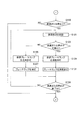
次に、図8A及び8Bのフローチャートを参照して、本実施形態に係る表示制御装置100の一動作例について説明する。 Next, an operation example of the display control device 100 according to the present embodiment will be described with reference to the flowcharts of FIGS. 8A and 8B.

ステップS101において、表示制御装置100は、自車両60が自動運転中か否かを判断する。例えば、表示制御装置100は、自車両60に設置された運転切替スイッチがオンの場合は、自車両60は自動運転中だと判断する。一方、運転切替スイッチがオフの場合は、表示制御装置100は、自車両60は自動運転中ではないと判断する。自車両60が自動運転中である場合(ステップS101でYes)、処理はステップS103に進む。一方、自車両60が自動運転中ではない場合(ステップS101でNo)、処理は待機する。 In step S101, the display control device 100 determines whether or not the own vehicle 60 is in automatic driving. For example, the display control device 100 determines that the own vehicle 60 is in automatic driving when the operation changeover switch installed in the own vehicle 60 is on. On the other hand, when the operation changeover switch is off, the display control device 100 determines that the own vehicle 60 is not in automatic operation. When the own vehicle 60 is in automatic operation (Yes in step S101), the process proceeds to step S103. On the other hand, when the own vehicle 60 is not in automatic operation (No in step S101), the process waits.

ステップS103において、乗員による車線変更の指示があった場合(ステップS103でYes)、処理はステップS105に進む。一方、乗員による車線変更の指示がない場合(ステップS103でNo)、処理はステップS119に進む。ステップS105において、周辺状況検出部22は、車線変更を行うための準備を開始する。周辺状況検出部22は、自車両60の周辺の状況を確認し、車線変更可能か否かを判断する。周辺状況検出部22が車線変更の準備を開始したとき、表示制御部23は、図2Aに示すように、ウィンカーインジケータ6bを連続点灯させる。また、表示制御部23は、仮想ターンシグナル8c’,8d’を連続点灯させる。これにより、乗員は、システムが車線変更の準備を開始したことを認識することができ、自車両60の状態を正確に把握することができる。車線変更ができない場合(ステップS107でNo)、処理はステップS109及びS111に進み、表示制御部23は、図2Aに示すように、ターンシグナル8c,8dを点灯させず、ウィンカーインジケータ6bを連続点灯させる。その後処理は、ステップS117に進む。一方、所定時間後に車線変更が可能である場合(ステップS107でYes)、処理はステップS113及びS115に進み、表示制御部23は、図2Bに示すように、ウィンカーインジケータ6bの点灯状態を、連続点灯から点滅点灯に切り替える。また、表示制御部23は、ウィンカーインジケータ6bの点灯状態に対応するように、ターンシグナル8c,8dの点灯状態を、消灯から点滅点灯に切り替える。これにより、表示制御部23は、乗員に対し、車線変更の準備が完了し、まもなく車線変更することを報知することができる。また、表示制御部23は、ターンシグナル8c,8dを点滅点灯させることにより、自車両60の周辺の他車両に対し、所定時間後に車線変更することを報知することができる。これにより、表示制御部23は、他車両の乗員に対し、自車両60が車線変更制御を開始する手前から、自車両60が車線変更することを報知することができる。これにより、他車両は、事前に減速して車間距離をあけるなどの他車両の乗員が違和感を感じるような挙動を抑制することができる。その後、処理はステップS117に進む。 If the occupant gives an instruction to change lanes in step S103 (Yes in step S103), the process proceeds to step S105. On the other hand, if there is no instruction from the occupant to change lanes (No in step S103), the process proceeds to step S119. In step S105, the peripheral situation detection unit 22 starts preparations for changing lanes. The surrounding condition detection unit 22 confirms the surrounding condition of the own vehicle 60 and determines whether or not the lane can be changed. When the surrounding condition detection unit 22 starts preparing for the lane change, the display control unit 23 continuously lights the blinker indicator 6b as shown in FIG. 2A. Further, the display control unit 23 continuously lights the virtual turn signals 8c'and 8d'. As a result, the occupant can recognize that the system has started preparing for the lane change, and can accurately grasp the state of the own vehicle 60. If the lane cannot be changed (No in step S107), the process proceeds to steps S109 and S111, and the display control unit 23 does not turn on the turn signals 8c and 8d and continuously turns on the blinker indicators 6b as shown in FIG. 2A. Let me. After that, the process proceeds to step S117. On the other hand, when the lane can be changed after a predetermined time (Yes in step S107), the process proceeds to steps S113 and S115, and the display control unit 23 continuously keeps the blinker indicator 6b lit as shown in FIG. 2B. Switch from lighting to blinking lighting. Further, the display control unit 23 switches the lighting state of the turn signals 8c and 8d from extinguished to blinking so as to correspond to the lighting state of the blinker indicator 6b. As a result, the display control unit 23 can notify the occupant that the preparation for changing lanes is completed and that the lane will be changed soon. Further, the display control unit 23 can notify other vehicles around the own vehicle 60 that the lane is changed after a predetermined time by blinking and lighting the turn signals 8c and 8d. As a result, the display control unit 23 can notify the occupants of the other vehicle that the own vehicle 60 will change lanes before the own vehicle 60 starts the lane change control. As a result, the other vehicle can suppress the behavior that the occupants of the other vehicle feel uncomfortable, such as decelerating in advance to increase the inter-vehicle distance. After that, the process proceeds to step S117.

ステップS117において、車両制御ECU31は、車線変更が終了したか否かを判断する。車線変更が終了したか否かの基準は、任意に設定できる。例えば、車両制御ECU31は、自車両60が白線(走行区分線)を跨いだ場合に、車線変更が終了したと判断してもよい。また、車体の8割が隣接車線に移動した場合に、車線変更が終了したと判断してもよく、車体が完全に隣接車線に移動した場合に、車線変更が終了したと判断してもよい。車線変更が終了した場合(ステップS117でYes)、処理はステップS135に進み、表示制御部23は、ウィンカーインジケータ6bを消灯させ、ターンシグナル8c,8dを消灯させる。一方、車線変更が終了していない場合(ステップS117でNo)、処理はステップS105に戻る。 In step S117, the vehicle control ECU 31 determines whether or not the lane change has been completed. The criteria for whether or not the lane change has been completed can be set arbitrarily. For example, the vehicle control ECU 31 may determine that the lane change has been completed when the own vehicle 60 crosses the white line (traveling division line). Further, when 80% of the vehicle body moves to the adjacent lane, it may be determined that the lane change is completed, and when the vehicle body completely moves to the adjacent lane, it may be determined that the lane change is completed. .. When the lane change is completed (Yes in step S117), the process proceeds to step S135, and the display control unit 23 turns off the blinker indicators 6b and turns off the turn signals 8c and 8d. On the other hand, if the lane change has not been completed (No in step S117), the process returns to step S105.

ステップS119において、乗員による減速または停止の指示があった場合(ステップS119でYes)、処理はステップS121に進む。一方、乗員による減速または停止の指示がない場合(ステップS119でNo)、処理はステップS135に進む。ステップS121において、周辺状況検出部22は、減速または停止を行うための準備を開始する。周辺状況検出部22は、自車両60の周辺の状況を確認し、減速または停止が可能か否かを判断する。周辺状況検出部22が減速または停止の準備を開始したとき、表示制御部23は、図5Aに示すように、仮想ブレーキランプ9a’,9b’を点滅点灯させる。これにより、表示制御部23は、乗員に対し、システムがブレーキを作動させる前に、ブレーキが作動することを報知することができる。これにより、実際にブレーキが作動しても乗員が感じる違和感は抑制される。 If the occupant gives an instruction to decelerate or stop in step S119 (Yes in step S119), the process proceeds to step S121. On the other hand, if there is no instruction from the occupant to decelerate or stop (No in step S119), the process proceeds to step S135. In step S121, the peripheral situation detection unit 22 starts preparations for decelerating or stopping. The peripheral situation detection unit 22 confirms the surrounding situation of the own vehicle 60 and determines whether or not deceleration or stop is possible. When the peripheral condition detection unit 22 starts preparing for deceleration or stop, the display control unit 23 blinks and lights the virtual brake lamps 9a'and 9b'as shown in FIG. 5A. As a result, the display control unit 23 can notify the occupant that the brake is activated before the system activates the brake. As a result, the discomfort felt by the occupant even when the brake is actually activated is suppressed.

減速または停止ができない場合(ステップS123でNo)、処理はステップS125及びS127に進み、表示制御部23は、図5Aに示すように、仮想ブレーキランプ9a’,9b’を点滅点灯させ、ブレーキランプ9a,9bを点灯させない。その後処理は、ステップS133に進む。 If deceleration or stop is not possible (No in step S123), the process proceeds to steps S125 and S127, and the display control unit 23 blinks and lights the virtual brake lamps 9a'and 9b'as shown in FIG. 5A, and the brake lamps Do not light 9a and 9b. After that, the process proceeds to step S133.

一方、減速または停止が可能である場合(ステップS123でYes)、システムは、ブレーキを作動させる。処理はステップS129及びS131に進み、図5Bに示すようにブレーキランプ9a,9bは連続点灯する。また、表示制御部23は、ブレーキランプ9a,9bの点灯状態に対応するように仮想ブレーキランプ9a’,9b’の点灯状態を、点滅点灯から連続点灯に切り替える。その後処理は、ステップS133に進む。 On the other hand, if deceleration or stop is possible (Yes in step S123), the system activates the brake. The process proceeds to steps S129 and S131, and the brake lamps 9a and 9b are continuously lit as shown in FIG. 5B. Further, the display control unit 23 switches the lighting state of the virtual brake lamps 9a'and 9b'from blinking lighting to continuous lighting so as to correspond to the lighting state of the brake lamps 9a and 9b. After that, the process proceeds to step S133.

減速または停止が終了した場合(ステップS113でYes)、処理はステップS135に進む。一方、減速または停止が終了していない場合(ステップS113でNo)、処理はステップS121に戻る。自動運転が終了した場合(ステップS135でYes)、一連の処理は終了する。一方、自動運転が終了していない場合(ステップS135でNo)、処理はステップS103に戻る。 When the deceleration or stop is completed (Yes in step S113), the process proceeds to step S135. On the other hand, if the deceleration or stop is not completed (No in step S113), the process returns to step S121. When the automatic operation is completed (Yes in step S135), the series of processes is completed. On the other hand, when the automatic operation is not completed (No in step S135), the process returns to step S103.

(作用効果)
以上説明したように、本実施形態に係る表示制御装置100によれば、以下の作用効果が得られる。
(Action effect)
As described above, according to the display control device 100 according to the present embodiment, the following effects can be obtained.

表示制御装置100は、システムが車線変更または右左折を行う際に、ターンシグナル8の点灯開始タイミングと、ウィンカーインジケータの点灯開始タイミングを異ならせる。これにより、乗員は、自車両60の状態を正確に把握することができる。これにより、表示制御装置100は、乗員が乗車中に感じる違和感を抑制することができる。 The display control device 100 makes the lighting start timing of the turn signal 8 different from the lighting start timing of the blinker indicator when the system changes lanes or turns left or right. As a result, the occupant can accurately grasp the state of the own vehicle 60. As a result, the display control device 100 can suppress the discomfort felt by the occupant while riding.

また、表示制御装置100は、ターンシグナル8を点灯させる前に、ウィンカーインジケータを点灯させる。例えば、図2Aに示すように、周辺状況検出部22が自車両60の周辺の状況を確認し、車線変更可能か否かを判断している場合、表示制御部23は、ウィンカーインジケータ6bを連続点灯させるが、ターンシグナル8c,8dを点灯させない。つまり、表示制御部23は、ターンシグナル8c,8dを点灯させる前にウィンカーインジケータ6bを点灯させる。これにより、表示制御部23は、乗員に対し、ターンシグナル8c,8dは点灯していないが、車線変更のために、ターンシグナル8c,8dが点灯準備状態(これから点灯することを示す状態)にあることを示すことができる。これにより、乗員は、自車両60の状態を正確に把握することができる。 Further, the display control device 100 turns on the blinker indicator before turning on the turn signal 8. For example, as shown in FIG. 2A, when the peripheral situation detection unit 22 confirms the surrounding situation of the own vehicle 60 and determines whether or not the lane can be changed, the display control unit 23 continuously displays the blinker indicator 6b. Turn on, but do not turn on the turn signals 8c and 8d. That is, the display control unit 23 turns on the blinker indicator 6b before turning on the turn signals 8c and 8d. As a result, the display control unit 23 puts the turn signals 8c and 8d into a lighting ready state (a state indicating that they will be lit) due to the lane change, although the turn signals 8c and 8d are not lit to the occupant. It can be shown that there is. As a result, the occupant can accurately grasp the state of the own vehicle 60.

ウィンカーインジケータの点灯開始タイミングと、車線変更の準備状態から車線変更制御を開始する状態に切り替わるタイミングは異なる。本実施形態では、ウィンカーインジケータの点灯開始タイミングは、車線変更の準備をしているときであり、車線変更制御を開始するときではない。乗員がウィンカースイッチ5を操作した場合にウィンカーインジケータの点灯が開始するが、ウィンカーインジケータの点灯が開始したタイミングが、必ずしもターンシグナル8が点灯するタイミングとして適切ではない。例えば、自動運転において、乗員が車線変更により先行車両の追い越しを指示した場合に、指示後すぐにはシステムが車線変更制御を実行することができない場合がある。その場合は、システムはタイミングを見計らって(周囲の他車両がいなくなるなど)、車線変更制御の実行を開始する必要がある。ターンシグナル8は、この車線変更制御の実行開始のタイミングに合わせて点灯を開始する必要があるが、乗員がウィンカースイッチ5を操作したタイミングでターンシグナル8の点灯を開始した場合、点灯の開始が早すぎて、周囲の他車両の走行に悪影響を与えてしまう場合がある。例えば、ターンシグナル8が点灯すると、この点灯を検出した他車両は、自車両60との車間距離をあけるために急ブレーキを行うことが考えられる。このような急ブレーキにより、他車両の乗員が違和感を感じるおそれがある。 The lighting start timing of the blinker indicator and the timing of switching from the lane change preparation state to the lane change control start state are different. In the present embodiment, the turn signal indicator lighting start timing is when the lane change is being prepared, not when the lane change control is started. When the occupant operates the blinker switch 5, the blinker indicator starts lighting, but the timing at which the blinker indicator starts lighting is not necessarily appropriate as the timing at which the turn signal 8 lights. For example, in automatic driving, when an occupant instructs to overtake a preceding vehicle by changing lanes, the system may not be able to execute lane change control immediately after the instruction. In that case, the system needs to start executing lane change control at the right time (for example, when there are no other vehicles around). The turn signal 8 needs to start lighting at the timing when the execution of the lane change control starts, but when the occupant starts lighting the turn signal 8 at the timing when the blinker switch 5 is operated, the lighting starts. It may be too fast and adversely affect the running of other vehicles around. For example, when the turn signal 8 is lit, it is conceivable that the other vehicle that has detected the lighting suddenly brakes in order to increase the distance from the own vehicle 60. Due to such sudden braking, the occupants of other vehicles may feel uncomfortable.

そこで、本実施形態では、乗員の1回目の指示を受けた周辺状況検出部22は、車線変更を行うための準備を開始する。このとき、表示制御部23は、図2Aに示すように、ウィンカーインジケータ6bを連続点灯させる。これにより、乗員は、システムが車線変更の準備を開始したことを認識することができ、自車両60の状態を正確に把握することができる。その後、乗員またはシステムが自車両60の周辺の状況を確認し、車線変更は可能であると判断した場合、乗員は2回目の指示を行う。2回目の指示を受けた表示制御部23は、ウィンカーインジケータ6bの点灯状態を、連続点灯から点滅点灯に切り替える。また、表示制御部23は、ウィンカーインジケータ6bの点灯状態に対応するように、ターンシグナル8c,8dの点灯状態を、消灯から点滅点灯に切り替える。これにより、表示制御部23は、乗員に対し、まもなく車線変更することを知らせることができる。また、表示制御部23は、ターンシグナル8c,8dを点滅点灯させることにより、自車両60の周辺の他車両に対し、所定時間後に車線変更することを知らせることができる。これにより、表示制御部23は、他車両の乗員に対して、自車両60が車線変更制御を開始する手前から、自車両60が車線変更することを知らせることができる。これにより、他車両は、事前に減速して車間距離をあけるなどの他車両の乗員が違和感を感じるような挙動を抑制することができる。 Therefore, in the present embodiment, the peripheral situation detection unit 22 that receives the first instruction of the occupant starts preparations for changing lanes. At this time, the display control unit 23 continuously lights the blinker indicator 6b as shown in FIG. 2A. As a result, the occupant can recognize that the system has started preparing for the lane change, and can accurately grasp the state of the own vehicle 60. After that, when the occupant or the system confirms the situation around the own vehicle 60 and determines that the lane can be changed, the occupant gives a second instruction. Upon receiving the second instruction, the display control unit 23 switches the lighting state of the blinker indicator 6b from continuous lighting to blinking lighting. Further, the display control unit 23 switches the lighting state of the turn signals 8c and 8d from extinguished to blinking so as to correspond to the lighting state of the blinker indicator 6b. As a result, the display control unit 23 can notify the occupant that the lane will be changed soon. Further, the display control unit 23 can notify other vehicles around the own vehicle 60 that the lane is changed after a predetermined time by blinking and lighting the turn signals 8c and 8d. As a result, the display control unit 23 can notify the occupants of the other vehicle that the own vehicle 60 will change lanes before the own vehicle 60 starts the lane change control. As a result, the other vehicle can suppress the behavior that the occupants of the other vehicle feel uncomfortable, such as decelerating in advance to increase the inter-vehicle distance.

また、乗員の指示の前に、表示制御部23は、図2Aに示すように、ウィンカーインジケータ6bを連続点灯させてもよい。これにより、乗員は、システムが車線変更の準備を開始したことを認識することができ、自車両60の状態を正確に把握することができる。その後、車線変更の準備が完了した場合、乗員の指示を受けた表示制御部23は、ウィンカーインジケータ6bの点灯状態を、連続点灯から点滅点灯に切り替える。また、表示制御部23は、ウィンカーインジケータ6bの点灯状態に対応するように、ターンシグナル8c,8dの点灯状態を、消灯から点滅点灯に切り替える。これにより、表示制御部23は、乗員に対し、まもなく車線変更することを知らせることができる。また、表示制御部23は、ターンシグナル8c,8dを点滅点灯させることにより、自車両60の周辺の他車両に対し、所定時間後に車線変更することを知らせることができる。これにより、表示制御部23は、他車両の乗員に対して、自車両60が車線変更制御を開始する手前から、自車両60が車線変更することを知らせることができる。これにより、他車両は、事前に減速して車間距離をあけるなどの他車両の乗員が違和感を感じるような挙動を抑制することができる。 Further, before the instruction of the occupant, the display control unit 23 may continuously turn on the blinker indicator 6b as shown in FIG. 2A. As a result, the occupant can recognize that the system has started preparing for the lane change, and can accurately grasp the state of the own vehicle 60. After that, when the preparation for changing lanes is completed, the display control unit 23, which receives the instruction from the occupant, switches the lighting state of the blinker indicator 6b from continuous lighting to blinking lighting. Further, the display control unit 23 switches the lighting state of the turn signals 8c and 8d from extinguished to blinking so as to correspond to the lighting state of the blinker indicator 6b. As a result, the display control unit 23 can notify the occupant that the lane will be changed soon. Further, the display control unit 23 can notify other vehicles around the own vehicle 60 that the lane is changed after a predetermined time by blinking and lighting the turn signals 8c and 8d. As a result, the display control unit 23 can notify the occupants of the other vehicle that the own vehicle 60 will change lanes before the own vehicle 60 starts the lane change control. As a result, the other vehicle can suppress the behavior that the occupants of the other vehicle feel uncomfortable, such as decelerating in advance to increase the inter-vehicle distance.

また、乗員の指示の後に、表示制御部23は、図2Aに示すように、ウィンカーインジケータ6bを連続点灯させてもよい。これにより、乗員は、自身の指示が反映されていることを認識することができ、自車両60の状態を正確に把握することができる。その後、車線変更の準備が完了した場合、表示制御部23は、乗員の指示を受けることなく、ウィンカーインジケータ6bの点灯状態を、連続点灯から点滅点灯に切り替えることができる。また、表示制御部23は、ウィンカーインジケータ6bの点灯状態に対応するように、ターンシグナル8c,8dの点灯状態を、消灯から点滅点灯に切り替えることができる。これにより、表示制御部23は、乗員に対し、まもなく車線変更することを知らせることができる。また、表示制御部23は、ターンシグナル8c,8dを点滅点灯させることにより、自車両60の周辺の他車両に対し、所定時間後に車線変更することを知らせることができる。これにより、表示制御部23は、他車両の乗員に対して、自車両60が車線変更制御を開始する手前から、自車両60が車線変更することを知らせることができる。これにより、他車両は、事前に減速して車間距離をあけるなどの他車両の乗員が違和感を感じるような挙動を抑制することができる。 Further, after the instruction of the occupant, the display control unit 23 may continuously turn on the blinker indicator 6b as shown in FIG. 2A. As a result, the occupant can recognize that his / her instruction is reflected, and can accurately grasp the state of the own vehicle 60. After that, when the preparation for changing lanes is completed, the display control unit 23 can switch the lighting state of the blinker indicator 6b from continuous lighting to blinking lighting without receiving instructions from the occupants. Further, the display control unit 23 can switch the lighting state of the turn signals 8c and 8d from turning off to blinking lighting so as to correspond to the lighting state of the blinker indicator 6b. As a result, the display control unit 23 can notify the occupant that the lane will be changed soon. Further, the display control unit 23 can notify other vehicles around the own vehicle 60 that the lane is changed after a predetermined time by blinking and lighting the turn signals 8c and 8d. As a result, the display control unit 23 can notify the occupants of the other vehicle that the own vehicle 60 will change lanes before the own vehicle 60 starts the lane change control. As a result, the other vehicle can suppress the behavior that the occupants of the other vehicle feel uncomfortable, such as decelerating in advance to increase the inter-vehicle distance.

また、表示制御装置100は、ウィンカーインジケータを点灯させた後、かつ、自車両60が車線変更制御または右左折制御を開始する前に、ターンシグナル8を点灯させる。これにより、表示制御装置100は、乗員に対し、車線変更または右左折の準備が完了し、まもなく車線変更することを報知することができる。また、表示制御装置100は、ターンシグナルを点滅点灯させることにより、自車両60の周辺の他車両に対し、所定時間後に車線変更することを報知することができる。これにより、表示制御装置100は、他車両の乗員に対し、自車両60が車線変更制御を開始する手前から、自車両60が車線変更することを報知することができる。これにより、他車両は、事前に減速して車間距離をあけるなどの他車両の乗員が違和感を感じるような挙動を抑制することができる。 Further, the display control device 100 turns on the turn signal 8 after turning on the blinker indicator and before the own vehicle 60 starts the lane change control or the right / left turn control. As a result, the display control device 100 can notify the occupant that the preparation for changing lanes or turning left or right is completed and that the lane will be changed soon. Further, the display control device 100 can notify other vehicles around the own vehicle 60 that the lane is changed after a predetermined time by blinking and lighting the turn signal. As a result, the display control device 100 can notify the occupants of the other vehicle that the own vehicle 60 will change lanes before the own vehicle 60 starts the lane change control. As a result, the other vehicle can suppress the behavior that the occupants of the other vehicle feel uncomfortable, such as decelerating in advance to increase the inter-vehicle distance.

また、ウィンカーインジケータの表示形態は、ターンシグナル8を点灯させる前と、ターンシグナル8を点灯させた後とで異なる。例えば、図2Aに示すように、周辺状況検出部22が車線変更の準備を行っている間は、表示制御部23は、ウィンカーインジケータ6bを連続点灯させるが、ターンシグナル8c,8dを点灯させない。そして、図2Bに示すように、車線変更の準備が完了した場合、表示制御部23は、ウィンカーインジケータ6bの点灯状態を、連続点灯から点滅点灯に切り替える。また、表示制御部23は、ウィンカーインジケータ6bの点灯状態に対応するように、ターンシグナル8c,8dの点灯状態を、消灯から点滅点灯に切り替える。つまり、ウィンカーインジケータ6bの表示形態は、ターンシグナルを点灯させる前は、連続点灯であり、ターンシグナルを点灯させた後は、点滅点灯である。このように、ウィンカーインジケータ6bの表示形態は、ターンシグナル8c,8dを点灯させる前と、ターンシグナル8c,8dを点灯させた後とで異なる。表示制御部23が、ターンシグナル8c,8dを点灯させる前は、ウィンカーインジケータ6bを連続点灯させることにより、表示制御部23は、車線変更の準備を開始したことを乗員に報知することができる。これにより、乗員は、自身の指示が反映されていることを認識することができ、自車両60の状態を正確に把握することができる。また、表示制御部23は、ウィンカーインジケータ6b及びターンシグナル8c,8dを点滅点灯させることにより、乗員に対し、車線変更の準備が完了し、まもなく車線変更することを報知することができる。 Further, the display form of the blinker indicator differs between before the turn signal 8 is turned on and after the turn signal 8 is turned on. For example, as shown in FIG. 2A, while the surrounding situation detection unit 22 is preparing to change lanes, the display control unit 23 continuously lights the blinker indicators 6b but does not turn on the turn signals 8c and 8d. Then, as shown in FIG. 2B, when the preparation for changing lanes is completed, the display control unit 23 switches the lighting state of the blinker indicator 6b from continuous lighting to blinking lighting. Further, the display control unit 23 switches the lighting state of the turn signals 8c and 8d from extinguished to blinking so as to correspond to the lighting state of the blinker indicator 6b. That is, the display form of the blinker indicator 6b is continuous lighting before turning on the turn signal, and blinking after turning on the turn signal. As described above, the display form of the blinker indicator 6b differs between before the turn signals 8c and 8d are turned on and after the turn signals 8c and 8d are turned on. Before the display control unit 23 lights the turn signals 8c and 8d, the blinker indicator 6b is continuously turned on, so that the display control unit 23 can notify the occupant that the preparation for changing lanes has started. As a result, the occupant can recognize that his / her instruction is reflected, and can accurately grasp the state of the own vehicle 60. Further, the display control unit 23 can notify the occupant that the preparation for changing lanes is completed and that the lane will be changed soon by blinking and lighting the blinker indicators 6b and the turn signals 8c and 8d.

また、表示制御装置100がターンシグナル8を点灯させた後、予め設定した所定時間後に、車両制御装置200は、車線変更制御または右左折制御を実行する。換言すれば、車両制御装置200が車線変更制御または右左折制御を実行する所定時間前に、表示制御装置100はターンシグナル8を点灯させる。これにより、表示制御装置100は、自車両60の周辺の他車両に対し、所定時間後に車線変更することを報知することができる。これにより、表示制御装置100は、他車両の乗員に対し、自車両60が車線変更制御を開始する手前から、自車両60が車線変更することを報知することができる。これにより、他車両は、事前に減速して車間距離をあけるなどの他車両の乗員が違和感を感じるような挙動を抑制することができる。 Further, after the display control device 100 turns on the turn signal 8 and a predetermined time set in advance, the vehicle control device 200 executes lane change control or right / left turn control. In other words, the display control device 100 turns on the turn signal 8 before the predetermined time when the vehicle control device 200 executes the lane change control or the right / left turn control. As a result, the display control device 100 can notify other vehicles around the own vehicle 60 to change lanes after a predetermined time. As a result, the display control device 100 can notify the occupants of the other vehicle that the own vehicle 60 will change lanes before the own vehicle 60 starts the lane change control. As a result, the other vehicle can suppress the behavior that the occupants of the other vehicle feel uncomfortable, such as decelerating in advance to increase the inter-vehicle distance.

また、表示制御装置100は、自車両60に設置されたブレーキランプ9a,9bを備える。また、図4Aに示す周辺画像70には、仮想ブレーキランプ9a’,9b’が表示される。なお、仮想ブレーキランプ9a’,9b’は、実際のブレーキランプ9a,9bとは異なるものである。表示制御装置100は、ブレーキランプ9a,9bの点灯開始タイミングと、仮想ブレーキランプ9a’,9b’の点灯開始タイミングを異ならせる。これにより、表示制御装置100は、乗員に対し、システムがブレーキを作動させる前に、ブレーキが作動することを報知することができる。これにより、実際にブレーキが作動しても乗員が感じる違和感は抑制される。すなわち、表示制御装置100は、乗員が乗車中に感じる違和感を抑制することができる。 Further, the display control device 100 includes brake lamps 9a and 9b installed in the own vehicle 60. Further, in the peripheral image 70 shown in FIG. 4A, virtual brake lamps 9a'and 9b' are displayed. The virtual brake lamps 9a'and 9b' are different from the actual brake lamps 9a and 9b. The display control device 100 makes the lighting start timings of the brake lamps 9a and 9b different from the lighting start timings of the virtual brake lamps 9a'and 9b'. Thereby, the display control device 100 can notify the occupant that the brake is activated before the system activates the brake. As a result, the discomfort felt by the occupant even when the brake is actually activated is suppressed. That is, the display control device 100 can suppress the discomfort felt by the occupant while riding.

また、表示制御装置100は、ターンシグナル8c,8dの点灯開始タイミングと、インジケータ6bの点灯開始タイミングと、ディスプレイ7による準備状態の表示の点灯開始タイミングとが異なるように、ターンシグナル8c,8d、ウィンカーインジケータ6b、ディスプレイ7を制御する。これにより、乗員は、ターンシグナル8c,8dの点灯状況や、ターンシグナル8c,8dがこれから点灯するのか、車両制御がこれから実行されるのか、を把握することができるようになるため、乗員は自車両60の状態を正確に把握することができるようになる。したがって、表示制御装置100は、乗員が乗車中に感じる違和感を抑制することができる。 Further, the display control device 100 has the turn signals 8c, 8d, so that the lighting start timings of the turn signals 8c and 8d, the lighting start timings of the indicators 6b, and the lighting start timings of the display 7 display 7 are different. The blinker indicator 6b and the display 7 are controlled. As a result, the occupant can grasp the lighting status of the turn signals 8c and 8d, whether the turn signals 8c and 8d are to be lit, and whether the vehicle control is to be executed. The state of the vehicle 60 can be accurately grasped. Therefore, the display control device 100 can suppress the discomfort felt by the occupant while riding.

(その他の実施形態)
上記のように、本発明の実施形態を記載したが、この開示の一部をなす論述及び図面はこの発明を限定するものであると理解すべきではない。この開示から当業者には様々な代替実施の形態、実施例及び運用技術が明らかとなろう。
(Other embodiments)
Although embodiments of the present invention have been described above, the statements and drawings that form part of this disclosure should not be understood to limit the invention. Various alternative embodiments, examples and operational techniques will be apparent to those skilled in the art from this disclosure.

例えば、乗員またはシステムは、車線変更または右左折を中止することができる。中止するタイミングは、特に限定されず、例えば、乗員またはシステムは、車線変更または右左折の準備が完了した後に、車線変更または右左折を中止することができる。車線変更または右左折の準備が完了している場合、図8AのステップS113及びステップS115に示すように、ウィンカーインジケータは点滅点灯しており、ターンシグナル8も点滅点灯している。このような場合に乗員またはシステムが、車線変更または右左折を中止した場合、表示制御部23は、ウィンカーインジケータを消灯させ、ターンシグナル8も消灯させる。その後、表示制御部23は、所定時間の間、ウィンカーインジケータ及びターンシグナル8の点灯を禁止する。 For example, the occupant or system may stop changing lanes or turning left or right. The timing of the stop is not particularly limited, and for example, the occupant or the system may stop the lane change or the right / left turn after the preparation for the lane change or the right / left turn is completed. When the preparation for changing lanes or turning left or right is completed, the blinker indicator is blinking and lit, and the turn signal 8 is also blinking and lit, as shown in steps S113 and S115 of FIG. 8A. In such a case, when the occupant or the system stops changing lanes or turning left or right, the display control unit 23 turns off the blinker indicator and turns off the turn signal 8. After that, the display control unit 23 prohibits the lighting of the blinker indicator and the turn signal 8 for a predetermined time.

なお、乗員またはシステムは、車線変更または右左折の準備が完了する前に、車線変更または右左折を中止することができる。車線変更または右左折の準備が完了していない場合、図8AのステップS109及びステップS111に示すように、ウィンカーインジケータは連続点灯しており、ターンシグナル8は消灯している。このような場合に乗員またはシステムが、車線変更または右左折を中止した場合、表示制御部23は、ウィンカーインジケータを消灯させる。その後、表示制御部23は、所定時間の間、ウィンカーインジケータ及びターンシグナル8の点灯を禁止する。 It should be noted that the occupant or system may cancel the lane change or right / left turn before the preparation for the lane change or right / left turn is completed. When the preparation for changing lanes or turning left or right is not completed, the blinker indicator is continuously lit and the turn signal 8 is extinguished, as shown in steps S109 and S111 of FIG. 8A. In such a case, when the occupant or the system stops changing lanes or turning left or right, the display control unit 23 turns off the blinker indicator. After that, the display control unit 23 prohibits the lighting of the blinker indicator and the turn signal 8 for a predetermined time.

1 物体検出装置
2 自車位置検出装置
3 地図取得装置
4 センサ群
5 ウィンカースイッチ
6 メータ
6a、6b ウィンカーインジケータ
7 ディスプレイ
8、8a、8b、8c、8d ターンシグナル
8a’、8b’、8c’、8d’ 仮想ターンシグナル
9、9a、9b ブレーキランプ
9a’、9b’ 仮想ブレーキランプ
10、10a、10b ヘッドランプ
10a’、10b’ 仮想ヘッドランプ
20 コントローラ
21 周辺画像生成部
22 周辺状況検出部
23 表示制御部
30 自車状態検出部
31 車両制御ECU
32 アクチュエータ
100 表示制御装置
200 車両制御装置
1 Object detection device 2 Own vehicle position detection device 3 Map acquisition device 4 Sensor group 5 Blinker switch 6 Meter 6a, 6b Blinker indicator 7 Display 8, 8a, 8b, 8c, 8d Turn signal 8a', 8b', 8c', 8d 'Virtual turn signals 9, 9a, 9b Brake lamps 9a', 9b' Virtual brake lamps 10, 10a, 10b Headlamps 10a', 10b' Virtual headlamps 20 Controller 21 Peripheral image generator 22 Peripheral situation detection unit 23 Display control unit 30 Own vehicle state detection unit 31 Vehicle control ECU
32 Actuator 100 Display control device 200 Vehicle control device

Claims (8)

車両に設置されたターンシグナルと、前記車両の乗員に前記ターンシグナルの点灯状態を表示するインジケータと、を備え、前記ターンシグナル及び前記インジケータの点灯状態を制御する表示制御装置の表示制御方法であって、
前記ターンシグナルの点灯開始タイミングと、前記インジケータの点灯開始タイミングとが異なり、
前記ターンシグナルを点滅点灯させる前に、前記インジケータを連続点灯させ、
前記乗員によってウィンカースイッチが操作された場合に、前記インジケータを連続点灯させ、
前記ターンシグナルを点滅点灯させた際に、前記インジケータの前記連続点灯を点滅点灯に変更する
ことを特徴とする表示制御方法。
It is a display control method of a display control device including a turn signal installed in a vehicle and an indicator for displaying the lighting state of the turn signal to the occupants of the vehicle, and controlling the lighting state of the turn signal and the indicator. hand,
The lighting start timing of the turn signal and the lighting start timing of the indicator are different.
Before blinking the turn signal, the indicator is continuously lit.
When the blinker switch is operated by the occupant, the indicator is continuously turned on.
A display control method characterized in that when the turn signal is blinked and lit, the continuous lighting of the indicator is changed to blinking lighting.
前記表示制御装置は、前記車両の周囲状況に合わせて算出された走行経路に基づいて実行される車両制御の制御状態を表示するディスプレイを備え、
前記ターンシグナルの点灯開始タイミングより前に、前記インジケータの点灯開始タイミングと、前記ディスプレイに表示される前記車両制御の制御状態の点灯開始タイミングとを設定し、
前記車両制御は、自動車線変更制御、自動右左折制御、自動ブレーキ制御のうち、少なくとも一つを含むことを特徴とする請求項1に記載の表示制御方法。
The display control device includes a display that displays a control state of vehicle control executed based on a travel route calculated according to the surrounding conditions of the vehicle.
Prior to the lighting start timing of the turn signal, the lighting start timing of the indicator and the lighting start timing of the control state of the vehicle control displayed on the display are set.
The display control method according to claim 1, wherein the vehicle control includes at least one of lane change control, automatic right / left turn control, and automatic brake control.
前記インジケータを点灯させた後、かつ、前記車両が車線変更制御または右左折制御を開始する前に、自動運転を制御するシステムが車線変更または右左折は可能であると判断した場合、前記ターンシグナルを点灯させることを特徴とする請求項1または2に記載の表示制御方法。 If the system controlling the automatic driving determines that lane change or right / left turn is possible after the indicator is turned on and before the vehicle starts lane change control or right / left turn control, the turn signal The display control method according to claim 1 or 2, wherein the light is turned on. 前記インジケータの表示形態は、前記ターンシグナルを点灯させる前と、前記ターンシグナルを点灯させた後とで異なることを特徴とする請求項1〜3のいずれか1項に記載の表示制御方法。 The display control method according to any one of claims 1 to 3, wherein the display form of the indicator is different before the turn signal is turned on and after the turn signal is turned on. 前記車両が前記車線変更制御または前記右左折制御を実行する所定時間前に、前記ターンシグナルを点灯させることを特徴とする請求項3に記載の表示制御方法。 The display control method according to claim 3, wherein the turn signal is turned on before a predetermined time when the vehicle executes the lane change control or the right / left turn control. 前記表示制御装置は、前記車両に設置されたブレーキランプをさらに備え、
前記ブレーキランプの点灯開始タイミングと、前記ブレーキランプの点灯状態を表示するブレーキインジケータの点灯開始タイミングが異なることを特徴とする請求項1〜5のいずれか1項に記載の表示制御方法。
The display control device further includes a brake lamp installed in the vehicle.
The display control method according to any one of claims 1 to 5, wherein the lighting start timing of the brake lamp and the lighting start timing of the brake indicator displaying the lighting state of the brake lamp are different.
前記インジケータを連続点灯させた後に、自動運転を制御するシステムが車線変更または右左折は不可能であると判断した場合、前記インジケータを消灯させる
ことを特徴とする請求項1〜6のいずれか1項に記載の表示制御方法。
Any one of claims 1 to 6, wherein the indicator is turned off when the system for controlling automatic driving determines that it is impossible to change lanes or turn left or right after the indicator is continuously turned on. The display control method described in the section.
車両に設置されたターンシグナルと、
前記車両の乗員に前記ターンシグナルの点灯状態を表示するインジケータと、
前記ターンシグナル及び前記インジケータの点灯状態を制御するコントローラと、を備え、
前記コントローラは、
前記ターンシグナルの点灯開始タイミングと、前記インジケータの点灯開始タイミングとを異ならせ、
前記ターンシグナルを点滅点灯させる前に、前記インジケータを連続点灯させ、
前記乗員によってウィンカースイッチが操作された場合に、前記インジケータを連続点灯させ、
前記ターンシグナルを点滅点灯させた際に、前記インジケータの前記連続点灯を点滅点灯に変更する
ことを特徴とする表示制御装置。
Turn signals installed on the vehicle and
An indicator that displays the lighting status of the turn signal to the occupants of the vehicle,
A controller for controlling the turn signal and the lighting state of the indicator is provided.
The controller
The lighting start timing of the turn signal and the lighting start timing of the indicator are made different.
Before blinking the turn signal, the indicator is continuously lit.
When the blinker switch is operated by the occupant, the indicator is continuously turned on.
When the turn signal is blinked, the continuous lighting of the indicator is changed to blinking.
A display control device characterized by the fact that.
JP2019532333A 2017-07-28 2017-07-28 Display control method and display control device Active JP6819787B2 (en)

Applications Claiming Priority (1)

Application Number Priority Date Filing Date Title
PCT/JP2017/027507 WO2019021471A1 (en) 2017-07-28 2017-07-28 Display control method and display control device

Publications (2)

Publication Number Publication Date
JPWO2019021471A1 JPWO2019021471A1 (en) 2020-10-08
JP6819787B2 true JP6819787B2 (en) 2021-01-27

Family

ID=65040726

Family Applications (1)

Application Number Title Priority Date Filing Date
JP2019532333A Active JP6819787B2 (en) 2017-07-28 2017-07-28 Display control method and display control device

Country Status (8)

Country Link
US (1) US10981495B2 (en)
EP (1) EP3659882B1 (en)
JP (1) JP6819787B2 (en)
KR (1) KR102215704B1 (en)
CN (1) CN111278701B (en)
CA (1) CA3071358A1 (en)
RU (1) RU2733025C1 (en)
WO (1) WO2019021471A1 (en)

Families Citing this family (18)

* Cited by examiner, † Cited by third party
Publication number Priority date Publication date Assignee Title
DE102017221619A1 (en) * 2017-11-30 2019-06-06 Volkswagen Aktiengesellschaft Method and device for indicating a feasibility of an at least partially automatically feasible driving maneuver in a vehicle
US11084490B2 (en) 2018-04-11 2021-08-10 Hyundai Motor Company Apparatus and method for controlling drive of vehicle
EP3552913B1 (en) 2018-04-11 2021-08-18 Hyundai Motor Company Apparatus and method for controlling to enable autonomous system in vehicle
US11597403B2 (en) 2018-04-11 2023-03-07 Hyundai Motor Company Apparatus for displaying driving state of vehicle, system including the same and method thereof
EP3569460B1 (en) 2018-04-11 2024-03-20 Hyundai Motor Company Apparatus and method for controlling driving in vehicle
EP3552901A3 (en) 2018-04-11 2020-04-29 Hyundai Motor Company Apparatus and method for providing safety strategy in vehicle
EP3552902A1 (en) 2018-04-11 2019-10-16 Hyundai Motor Company Apparatus and method for providing a driving path to a vehicle
US11077854B2 (en) 2018-04-11 2021-08-03 Hyundai Motor Company Apparatus for controlling lane change of vehicle, system having the same and method thereof
US11351989B2 (en) 2018-04-11 2022-06-07 Hyundai Motor Company Vehicle driving controller, system including the same, and method thereof
US11548509B2 (en) * 2018-04-11 2023-01-10 Hyundai Motor Company Apparatus and method for controlling lane change in vehicle
US10843710B2 (en) 2018-04-11 2020-11-24 Hyundai Motor Company Apparatus and method for providing notification of control authority transition in vehicle
US11084491B2 (en) 2018-04-11 2021-08-10 Hyundai Motor Company Apparatus and method for providing safety strategy in vehicle
US11173910B2 (en) 2018-04-11 2021-11-16 Hyundai Motor Company Lane change controller for vehicle system including the same, and method thereof
US11334067B2 (en) 2018-04-11 2022-05-17 Hyundai Motor Company Apparatus and method for providing safety strategy in vehicle
CN112236805B (en) * 2018-06-08 2022-08-09 三菱电机株式会社 Travel plan information distribution system
JP6818788B2 (en) * 2019-02-05 2021-01-20 本田技研工業株式会社 Vehicle and its control device and control method
CN113851011A (en) * 2020-06-28 2021-12-28 本田技研工业株式会社 Information processing apparatus, control method for information processing apparatus, communication apparatus, control method for communication apparatus, and medium
JP7474136B2 (en) * 2020-06-30 2024-04-24 本田技研工業株式会社 Control device, control method, and program

Family Cites Families (27)

* Cited by examiner, † Cited by third party
Publication number Priority date Publication date Assignee Title
US3422421A (en) * 1964-10-09 1969-01-14 Bosch Gmbh Robert Blinker type signal system with indication of defective blinker lamp
DE69333255T2 (en) * 1992-07-20 2004-08-12 Aisin AW Co., Ltd., Anjo Navigation device for vehicles with roundabout detection
NL1011534C2 (en) * 1999-03-11 2000-09-12 Richard Cornelis Maijers Device for controlling a lamp of a vehicle.
JP4734743B2 (en) * 2001-03-30 2011-07-27 株式会社デンソー Vehicle instrument
JP2003194566A (en) 2001-12-25 2003-07-09 Ftl International:Kk Car navigation system
JP3991915B2 (en) * 2003-05-12 2007-10-17 日産自動車株式会社 VEHICLE DRIVE OPERATION ASSISTANCE DEVICE AND VEHICLE HAVING THE DEVICE
JP2005001582A (en) * 2003-06-13 2005-01-06 Nissan Motor Co Ltd Direction indicator
JP2006177862A (en) * 2004-12-24 2006-07-06 Aisin Aw Co Ltd Navigation apparatus
JP2006264624A (en) * 2005-03-25 2006-10-05 Daimler Chrysler Ag Lane maintaining assistant device
JP2007283933A (en) 2006-04-18 2007-11-01 Nissan Motor Co Ltd Operation support device, automobile, and operation support method
JP2008037167A (en) * 2006-08-02 2008-02-21 Mazda Motor Corp Vehicular information display device
JP5171629B2 (en) * 2006-09-04 2013-03-27 パナソニック株式会社 Driving information providing device
JP4561722B2 (en) * 2006-10-04 2010-10-13 アイシン・エィ・ダブリュ株式会社 Driving assistance device
JP4966736B2 (en) * 2007-05-21 2012-07-04 本田技研工業株式会社 Vehicle operation support device
EP2017162B1 (en) * 2007-07-19 2013-06-12 Nissan Motor Co., Ltd. In-lane running support system, automobile and in-lane running support method
CN102047304B (en) 2008-08-05 2013-04-03 松下电器产业株式会社 Driver awareness degree judgment device, method, and program
JP5027756B2 (en) 2008-08-06 2012-09-19 本田技研工業株式会社 Driving assistance device
JP5210233B2 (en) * 2009-04-14 2013-06-12 日立オートモティブシステムズ株式会社 Vehicle external recognition device and vehicle system using the same
JP5204038B2 (en) * 2009-06-03 2013-06-05 株式会社東海理化電機製作所 Turn signal lighting control device
DE102009048493A1 (en) * 2009-09-25 2011-04-07 Valeo Schalter Und Sensoren Gmbh A driver assistance system for a vehicle, vehicle with a driver assistance system, and method for assisting a driver in driving a vehicle
US8847771B2 (en) * 2013-01-25 2014-09-30 Toyota Motor Engineering & Manufacturing North America, Inc. Method and apparatus for early detection of dynamic attentive states for providing an inattentive warning
DE102013207581A1 (en) * 2013-04-25 2014-10-30 Robert Bosch Gmbh Method for automatically actuating a direction indicator of a motor vehicle
JP6056682B2 (en) 2013-06-27 2017-01-11 株式会社デンソー Vehicle information providing device
JP6413933B2 (en) * 2015-06-02 2018-10-31 株式会社デンソー Retreat travel control device and retreat travel control method
JP6560050B2 (en) 2015-07-30 2019-08-14 クラリオン株式会社 Lighting control device for direction indicator
JP2017058761A (en) * 2015-09-14 2017-03-23 株式会社デンソー Driving assistance device and driving assistance program
JP6620527B2 (en) 2015-11-19 2019-12-18 株式会社デンソー Information processing apparatus and in-vehicle system

Also Published As

Publication number Publication date
RU2733025C1 (en) 2020-09-28
CA3071358A1 (en) 2019-01-31
US20200269747A1 (en) 2020-08-27
KR102215704B1 (en) 2021-02-16
US10981495B2 (en) 2021-04-20
BR112020001736A2 (en) 2020-07-21
EP3659882B1 (en) 2021-06-09
JPWO2019021471A1 (en) 2020-10-08
EP3659882A1 (en) 2020-06-03
KR20200032176A (en) 2020-03-25
EP3659882A4 (en) 2020-07-29
CN111278701A (en) 2020-06-12
WO2019021471A1 (en) 2019-01-31
CN111278701B (en) 2023-05-02

Similar Documents

Publication Publication Date Title
JP6819787B2 (en) Display control method and display control device
JP7249914B2 (en) Driving control device and in-vehicle system
JP6490044B2 (en) Vehicle control device
JP6617534B2 (en) Driving assistance device
US10857999B2 (en) Vehicle device
JP6489084B2 (en) Automated driving system
CN116373879A (en) Travel control device and travel control method
JP2016071514A (en) Driving support control device
JP6607826B2 (en) Travel control device
WO2020230613A1 (en) Display control method and display control device
JP7119653B2 (en) vehicle controller
JP2018088055A (en) Vehicle driving support device
JP2019001314A (en) Driving support equipment and control program
JP2019191982A (en) Vehicle remote operation support system
JP2018024351A (en) Automatic operation system
WO2019087975A1 (en) Vehicle control device
JP2017094964A (en) On-vehicle system and information processor
JP2022140032A (en) Driving support device and vehicle
JP7139632B2 (en) AUTOMATIC DRIVING CONTROL ECU FOR VEHICLE AND AUTOMATIC DRIVING CONTROL METHOD
JP2012118870A (en) Driving support apparatus
JP7275985B2 (en) display controller
JP2020082749A (en) Vehicle control apparatus
US11897507B2 (en) Vehicle control device
WO2023100741A1 (en) Vehicle, control device for same, and control method
WO2023157721A1 (en) Vehicle control device and vehicle control method

Legal Events

Date Code Title Description
A529 Written submission of copy of amendment under article 34 pct

Free format text: JAPANESE INTERMEDIATE CODE: A5211

Effective date: 20200122

A521 Request for written amendment filed

Free format text: JAPANESE INTERMEDIATE CODE: A523

Effective date: 20200228

A621 Written request for application examination

Free format text: JAPANESE INTERMEDIATE CODE: A621

Effective date: 20200228

TRDD Decision of grant or rejection written
A01 Written decision to grant a patent or to grant a registration (utility model)

Free format text: JAPANESE INTERMEDIATE CODE: A01

Effective date: 20201201

A61 First payment of annual fees (during grant procedure)

Free format text: JAPANESE INTERMEDIATE CODE: A61

Effective date: 20201214

R151 Written notification of patent or utility model registration

Ref document number: 6819787

Country of ref document: JP

Free format text: JAPANESE INTERMEDIATE CODE: R151