WO2023157721A1 - Vehicle control device and vehicle control method - Google Patents
Vehicle control device and vehicle control method Download PDFInfo
- Publication number
- WO2023157721A1 WO2023157721A1 PCT/JP2023/003999 JP2023003999W WO2023157721A1 WO 2023157721 A1 WO2023157721 A1 WO 2023157721A1 JP 2023003999 W JP2023003999 W JP 2023003999W WO 2023157721 A1 WO2023157721 A1 WO 2023157721A1
- Authority
- WO
- WIPO (PCT)
- Prior art keywords
- vehicle
- following
- change lanes
- following vehicle
- lane
- Prior art date
Links
Images


Classifications
-
- B—PERFORMING OPERATIONS; TRANSPORTING
- B60—VEHICLES IN GENERAL
- B60W—CONJOINT CONTROL OF VEHICLE SUB-UNITS OF DIFFERENT TYPE OR DIFFERENT FUNCTION; CONTROL SYSTEMS SPECIALLY ADAPTED FOR HYBRID VEHICLES; ROAD VEHICLE DRIVE CONTROL SYSTEMS FOR PURPOSES NOT RELATED TO THE CONTROL OF A PARTICULAR SUB-UNIT
- B60W50/00—Details of control systems for road vehicle drive control not related to the control of a particular sub-unit, e.g. process diagnostic or vehicle driver interfaces
- B60W50/08—Interaction between the driver and the control system
- B60W50/14—Means for informing the driver, warning the driver or prompting a driver intervention
-
- B—PERFORMING OPERATIONS; TRANSPORTING
- B60—VEHICLES IN GENERAL
- B60W—CONJOINT CONTROL OF VEHICLE SUB-UNITS OF DIFFERENT TYPE OR DIFFERENT FUNCTION; CONTROL SYSTEMS SPECIALLY ADAPTED FOR HYBRID VEHICLES; ROAD VEHICLE DRIVE CONTROL SYSTEMS FOR PURPOSES NOT RELATED TO THE CONTROL OF A PARTICULAR SUB-UNIT
- B60W60/00—Drive control systems specially adapted for autonomous road vehicles
-
- G—PHYSICS
- G08—SIGNALLING
- G08G—TRAFFIC CONTROL SYSTEMS
- G08G1/00—Traffic control systems for road vehicles
- G08G1/16—Anti-collision systems
Definitions
- the present disclosure relates to technology for assisting a driver to change lanes or for automatically executing lane changes.
- Triggered by the activation of the vehicle's direction indicators it detects a vehicle approaching from the rear side of the vehicle and alerts the driver according to the distance between the vehicle and the relative speed of the vehicle.
- Patent Document 1 it is predicted that the vehicle may change lanes based on the inter-vehicle distance or the approach speed between the vehicle and the preceding vehicle, and based on the prediction result, the vehicle approaches from the rear side. A configuration is described for notifying the driver of the presence of a vehicle that is approaching.
- the vehicle behind your vehicle may also start changing lanes.
- the host vehicle and the other vehicle may start changing lanes at substantially the same timing.
- there is an obstacle such as a car parked in front of the vehicle, and the vehicle must move to an adjacent lane to avoid a collision.
- a driver who is about to change lanes pays attention to the traffic conditions in the adjacent lane to which he or she is moving, it is difficult for him to turn his attention to the following vehicle that is directly behind him, and he does not notice that the following vehicle is about to change lanes. Hard to notice.
- the present disclosure has been made based on the above considerations or points of focus, and one of its purposes is to provide a vehicle control device and a vehicle control method that enable safer lane changes. .
- a first vehicle control device disclosed herein controls the vehicle to travel in the same lane behind the own vehicle based on a signal from a rearward monitoring sensor that outputs information about an object existing behind the own vehicle.
- a following vehicle behavior determination unit that determines whether or not a following vehicle, which is another vehicle that is a vehicle that does not change lanes, is about to change lanes, and the following vehicle behavior determination unit determines that the following vehicle is about to change lanes.
- a vehicle control unit that performs following vehicle warning processing, which is processing for notifying the driver that the vehicle is about to change lanes.
- a second vehicle control device of the present disclosure drives the vehicle behind the own vehicle in the same lane as the own vehicle based on a signal from a rearward monitoring sensor that outputs information about an object existing behind the own vehicle.
- a following vehicle behavior determination unit that determines whether or not a following vehicle is about to change lanes, and a control that automatically changes lanes according to traffic conditions or according to a previously set driving plan. and a vehicle control unit that implements the following vehicle behavior determination unit when the following vehicle behavior determination unit determines that the following vehicle is about to change lanes in a situation where the vehicle is about to change lanes. lane changes are canceled or postponed.
- a vehicle control method of the present disclosure is a vehicle control method that is executed by a vehicle control device that is mounted on and used in a vehicle. Based on this, it is determined whether or not the following vehicle, which is another vehicle behind the own vehicle and is traveling in the same lane as the own vehicle, is about to change lanes, and it is determined that the following vehicle is about to change lanes. and executing a following vehicle warning process, which is a process for notifying the driver that the following vehicle is about to change lanes.
- the above method is a method corresponding to the above first vehicle control device, and can obtain the same effect by the same action as the first vehicle control device.
- FIG. 1 is a block diagram showing a configuration example of an in-vehicle system
- FIG. It is a block diagram showing an example of a perimeter monitoring sensor.
- 3 is a functional block diagram of a vehicle control ECU
- FIG. 4 is a diagram for explaining an example of a method for determining that a following vehicle is about to change lanes
- FIG. 10 is a flowchart corresponding to processing for determining that a following vehicle is about to change lanes based on a lateral position change amount and determining the direction of movement thereof
- FIG. FIG. 5 is a diagram for explaining another example of a method of determining that a following vehicle is about to change lanes
- 4 is a diagram for explaining another example of a method of determining that a following vehicle is about to change lanes;
- 4 is a flow chart showing the operation of a vehicle control ECU;
- 4 is a flowchart showing another operation example of the vehicle control ECU; It is a figure which shows an example of the following vehicle warning process according to the state of the own vehicle.
- 4 is a flowchart showing another operation example of the vehicle control ECU; It is a figure for demonstrating the distant parallel running vehicle.
- 4 is a flowchart for explaining the operation of a vehicle control ECU that takes into consideration the behavior of a vehicle running in parallel at a distance;
- FIG. 1 is a diagram showing an example of a schematic configuration of an in-vehicle system Sys according to this embodiment.
- the present disclosure can be implemented with appropriate modifications so as to comply with local laws and customs where the in-vehicle system Sys is used.
- the present disclosure is applicable not only to passenger cars but also to various vehicles that can travel on roads, such as tank trucks and trucks.
- the vehicle on which the in-vehicle system Sys is mounted is also referred to as the own vehicle.
- the own vehicle may be an electric vehicle.
- the own vehicle may be an engine vehicle.
- the concept of electric vehicles can include not only electric vehicles but also plug-in hybrid vehicles, hybrid vehicles, and fuel cell vehicles.
- a driver in the present disclosure refers to a person sitting in the driver's seat, that is, a driver's seat occupant. Assuming that the vehicle is remotely controlled, the person who remotely controls the vehicle (so-called operator) also corresponds to the driver.
- the in-vehicle system Sys includes a vehicle state sensor 11, a surroundings monitoring sensor 12, a driver monitor 13, a wireless communication device 14, a display 21, a speaker 22, a vibrator 23, an input device 24, and a vehicle control ECU 30.
- ECU in the member name is an abbreviation of Electronic Control Unit, meaning an electronic control unit.
- the vehicle state sensor 11 is a sensor that detects information regarding the state of the vehicle.
- a vehicle speed sensor, a steering angle sensor, a steering sensor, etc. correspond to the vehicle state sensor 11 .
- a vehicle speed sensor detects the vehicle speed of the own vehicle.
- a steering angle sensor detects a steering angle.
- a steering sensor is a sensor that detects torque (so-called steering torque) applied to a steering wheel by a driver.
- the steering sensor may be a sensor that detects the steering angle, which is the rotation angle of the steering wheel.
- the vehicle state sensor 11 outputs a signal indicating the current value/state of the item to be detected to the vehicle control ECU 30 .
- the type of sensor that the in-vehicle system Sys should have as the vehicle state sensor 11 may be appropriately designed.
- the in-vehicle system Sys need not include all the sensors described above. Further, the in-vehicle system Sys may include sensors other than those described above as the vehicle state sensor 11 .
- the operating state of the direction indicators and the state of the power supply for driving also correspond to information related to the state of the vehicle.
- the power supply for running is a power supply for running the vehicle, and indicates an ignition power supply when the vehicle is an engine vehicle.
- the running power supply refers to the system main relay.
- the vehicle control ECU 30 can also receive a signal indicating the operating state of the direction indicator and the state of the power supply for driving.
- a vehicle speed sensor, a direction indicator switch, and the like correspond to in-vehicle sensors that detect the state of the own vehicle.
- the surroundings monitoring sensor 12 is an autonomous sensor that monitors the surroundings of the vehicle.
- a camera that captures an image of the outside of the vehicle, millimeter wave radar, LiDAR, sonar, and the like correspond to the peripheral monitoring sensor 12 .
- the surroundings monitoring sensor 12 detects predetermined moving and stationary objects from the detection range around the vehicle, and also detects their positions and moving speeds.
- LiDAR is an abbreviation for Light Detection and Ranging or Laser Imaging Detection and Ranging.
- Millimeter-wave radar transmits search waves such as millimeter waves or quasi-millimeter waves, and analyzes the reception data of the reflected waves that are reflected by the object to determine the relative position of the object with respect to the vehicle.
- LiDAR is a device that detects an object existing within a predetermined detection area based on the reception result of laser light of a predetermined wavelength such as infrared light or near-infrared light.
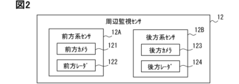
- the in-vehicle system Sys of this embodiment includes, as the peripheral monitoring sensors 12, a front sensor 12A forming a detection area in front of the vehicle and a rear sensor forming a detection area behind the vehicle as shown in FIG. 12B.
- the front includes not only the straight front but also the oblique front.
- the rear includes not only directly behind but also obliquely behind.
- the in-vehicle system Sys includes a front camera 121 and a front radar 122 as front sensors 12A. Also, the in-vehicle system Sys includes a rear camera 123 and a rear radar 124 as the rear system sensor 12B. A detection result of each periphery monitoring sensor 12 is input to the vehicle control ECU 30 . The rear system sensor 12B corresponds to a rear monitoring sensor.
- the front camera 121 is an optical/infrared camera arranged to capture an image in front of the vehicle with a predetermined angle of view.
- the front camera 121 is arranged at the upper end of the windshield on the interior side of the vehicle, the front grille, the roof top, or the like.
- the front camera 121 detects moving objects such as pedestrians and other vehicles by performing recognition processing on image frames.
- the front camera 121 also detects the lighting state of a lighting device provided on the back of the preceding vehicle by analyzing the image.
- the front camera 121 also detects road markings, road edges, road signs, and the like.
- a pavement marking is a piece of paint painted on the pavement for the purpose of controlling or directing traffic on the road. In one aspect, pavement markings can be referred to as pavement paint.
- Road markings include lane markings indicating lane boundaries, stop lines, and regulatory arrows.
- Lane boundaries include white or yellow continuous lines (solid lines) or dashed lines of paint, as well as those realized by road studs such as Chatterbars and Bots Dots.
- the front radar 122 is a millimeter-wave radar installed on the front of the vehicle, such as the front grille and front bumper.
- the front radar 122 detects the distance, relative speed, and relative position to an object such as a preceding vehicle on the lane of the vehicle.
- the preceding vehicle in the present disclosure refers to a vehicle that runs in the same lane as the own vehicle and is closest to the own vehicle among the vehicles existing in front of the own vehicle.
- the trailing vehicle refers to a vehicle that runs in the same lane as the vehicle and that is closest to the vehicle, among vehicles behind the vehicle.
- the vehicle lane among the lanes provided on the road on which the vehicle is traveling, the lane on which the vehicle is traveling is referred to as the vehicle lane.
- the host vehicle lane can also be called an ego lane.
- the rear camera 123 is an optical/infrared camera arranged to capture an image of the rear of the vehicle with a predetermined angle of view.
- the rear camera 123 is arranged at an arbitrary position on the rear surface of the vehicle, such as near the upper end of the rear glass.
- the rear camera 123 detects moving objects, road markings, road edges, and the like by performing recognition processing on image frames. A following vehicle may be included in the moving object to be detected.
- the rear camera 123 detects the operating state of the direction indicator of the following vehicle by analyzing the image.
- the rear radar 124 is a millimeter wave radar installed on the rear bumper. The rear radar 124 detects relative positions and relative velocities of other vehicles, following vehicles, and the like present behind the vehicle.
- the above-described perimeter monitoring sensors 12 are merely examples, and the in-vehicle system Sys need not include all of the perimeter monitoring sensors 12 described above.
- the in-vehicle system Sys may also include a side camera that captures images of the sides of the vehicle. Side cameras are provided on left and right side mirrors. The side camera also analyzes the image to generate a signal that indicates the behavior of other vehicles on the side. The traffic situation behind the vehicle may be acquired by analyzing the video captured by the side camera.
- a device external to the camera, the vehicle control ECU 30, may have the function of detecting the behavior of other vehicles by analyzing the camera image.
- each of the N cameras serving as surrounding monitoring sensors outputs video signals to the vehicle control ECU 30 .
- a video signal itself of a camera that captures an image of the outside of the vehicle can also correspond to a signal that indicates the behavior of another vehicle.
- the driver monitor 13 is a sensor that includes a camera arranged to capture an image of the driver, and detects the state of the driver by analyzing the image of the camera.
- the driver monitor 13 is arranged on the upper surface of the steering column cover, the upper surface of the instrument panel, the upper end of the windshield, etc., with the optical axis facing the headrest of the driver's seat.
- the camera included in the driver monitor 13 may be a visible light camera or an infrared camera.
- the driver monitor 13 sequentially detects the state of the driver based on the face image of the driver included in the captured video.
- the driver monitor 13 sequentially detects, as the state of the driver, the orientation of the driver's face, the line-of-sight direction, the degree of eyelid opening (so-called eye opening degree), and the like.
- the driver monitor 13 sequentially outputs information indicating the state of the driver identified from the captured image to the vehicle control ECU 30 as driver state data.
- the vehicle control ECU 30 may have the function of detecting the state of the driver or the like by analyzing the video signal of the camera.
- the driver monitor 13 also corresponds to an in-vehicle sensor that detects the behavior of the driver.
- the wireless communication device 14 is a device for carrying out wireless communication between the vehicle and other devices.
- Wireless communication device 14 is configured to be capable of performing cellular communication.
- Cellular communication is wireless communication conforming to standards such as LTE (Long Term Evolution), 4G, and 5G.
- Radio 14 may be configured to implement cellular V2X (PC5/Uu).
- the wireless communication device 14 is configured to be capable of performing short-range communication.
- Short-range communication in the present disclosure refers to wireless communication in which the communicable distance is limited to within several hundred meters.
- DSRC Dedicated Short Range Communications
- Wi-Fi registered trademark
- the short range communication may be the aforementioned cellular V2X.
- the short-range communication with other vehicles is also called inter-vehicle communication.
- the wireless communication device 14 may be configured to be capable of performing only one of cellular communication and short-range communication.
- the wireless communication device 14 can acquire dynamic map data corresponding to the current position from an external device such as a map distribution server or a roadside device.
- Dynamic map data is map data indicating the positions of obstacles on roads. Vehicles parked on the road, construction sections, lane restriction sections, fallen objects, and the like correspond to obstacles.
- the radio communication device 14 can receive vehicle information from the preceding vehicle and the following vehicle through inter-vehicle communication. The vehicle information may include the lighting status of hazard lamps, vehicle speed, operating status of direction indicators, steering angle, and the like.
- the data received by the wireless communication device 14 is transmitted to the vehicle control ECU 30 .
- the display 21 is a device that displays images.
- the in-vehicle system Sys includes, as a display 21, one or more of a head-up display (HUD: Head-Up Display), a meter display, and a center display.
- a HUD is a device that projects an image onto a predetermined area of a windshield to display an image in a position that overlaps with the scenery in front.
- the meter display is a display arranged in the area located in front of the driver's seat on the instrument panel.
- a center display is a display provided in the central part of the instrument panel.
- a meter display and a center display can be realized using a liquid crystal display or an organic EL display.
- the display 21 displays an image corresponding to the input signal based on the control signal and the video signal input from the vehicle control ECU 30 .
- the speaker 22 is a device that outputs sounds corresponding to signals input from the vehicle control ECU 30 .
- the expression of "sound” includes not only notification sound but also voice, music, and the like.
- the vibrator 23 is a device for applying vibration stimulation to the driver, and is provided on the steering wheel and the backrest of the driver's seat. The vibrator 23 may be arranged at multiple locations. Note that the vibrator 23 may be a device that applies a vibration stimulus to the driver by vibrating the seat belt itself.
- the in-vehicle system Sys may be equipped with an ambient light or the like as a notification device.
- Ambient lights are lighting devices that are realized by a plurality of LEDs (light emitting diodes) and are capable of adjusting emission colors and emission intensities, and are provided in instrument panels, steering wheels, and the like.
- the vehicle control ECU 30 may be configured to be able to perform control for tightening the seat belt of the driver's seat by a predetermined amount. Seatbelt tightening can also be used as a stimulus to alert the driver.
- the input device 24 is a device for receiving the driver's instruction operation to the in-vehicle system Sys.
- a steering switch provided on the spoke portion of the steering wheel, a touch panel laminated on the center display, or the like can be adopted.
- the in-vehicle system Sys may include multiple types of devices as the input device 24 .
- An operating member for activating the turn signals, a so-called turn signal lever/switch, may also be included in input device 24 .
- the input device 24 can also include a device for voice input, such as a microphone.
- the input device 24 outputs an electrical signal corresponding to the driver's operation to the vehicle control ECU 30 as an operation signal.
- the display 21, speaker 22, vibrator 23, and input device 24 constitute an in-vehicle HMI (Human Machine Interface).
- An HCU HMI Control Unit
- the HCU is a device that comprehensively controls information notification to the driver.
- the vehicle control ECU 30 is an ECU that controls the presentation of information to the driver regarding lane changes and the like.
- the vehicle control ECU 30 may be configured to be able to perform vehicle control such as ACC (Adaptive Cruise Control).
- ACC keeps the vehicle running at a predetermined target speed when there is no preceding vehicle within a predetermined distance, and maintains the following distance from the preceding vehicle when there is a preceding vehicle within the predetermined distance. It refers to a control function that allows the vehicle to follow the vehicle while it is moving.
- ACC is started based on an instruction from the crew.
- the ACC target speed may be entered by the driver, or a speed limit determined by map data or road sign recognition may be applied.
- the vehicle control ECU 30 is mainly composed of a computer including a processor 31, a storage 32, a memory 33, a communication interface 34, and a bus connecting them.
- the processor 31 is a calculation core such as a CPU (Central Processing Unit) or a GPU (Graphics Processing Unit).
- the processor 31 accesses the memory 33 to perform various processes.
- the storage 32 is rewritable non-volatile such as flash memory.
- the storage 32 stores a vehicle control program, which is a program for causing a normal computer to function as the vehicle control ECU 30 .
- the vehicle control program includes a notification control program for controlling presentation of information to passengers. Execution of the vehicle control program by the processor 31 corresponds to execution of the vehicle control method.
- the memory 33 is a rewritable volatile storage medium and RAM (Random Access Memory).
- the vehicle control ECU 30 corresponds to a vehicle control device.
- the vehicle control ECU 30 includes, as functional units, an information acquisition unit F1, an other vehicle LC determination unit F2, an own vehicle LC determination unit F3, and a vehicle control unit F4. These functional units are implemented by the processor 31 executing the vehicle control program.
- the description of "LC” in this disclosure means a lane change (Lane Change).
- the description of the LC determination unit can be read as the lane change determination unit.
- the information acquisition unit F1 acquires various information from the vehicle state sensor 11 and the like, and temporarily stores it in the memory 33.
- the information acquisition unit F1 acquires the vehicle's running speed, acceleration, steering state, operation state of the direction indicator, and the like from the vehicle state sensor 11 .
- the information acquisition unit F ⁇ b>1 also acquires detection results from the periphery monitoring sensor 12 .
- the information acquisition unit F1 acquires the relative speed and relative position of the preceding vehicle and the following vehicle, the operation state of the direction indicator, the lighting state of the brake lamp/hazard lamp, and the like.
- the information acquisition unit F1 acquires the positions of lane lines existing on the left and right of the own vehicle, the positions of road edges, and the like. Positional information such as other vehicles and lane markings may be expressed in a two-dimensional or three-dimensional relative coordinate system with the own vehicle as a reference.
- the information acquisition unit F1 can acquire the position, speed, acceleration, operating state of the direction indicator, etc. of the following vehicle based on the image of the rear camera 123 or the signal received by inter-vehicle communication. Furthermore, the information acquisition unit F1 acquires position information of obstacles existing on the vehicle lane based on the detection result of the forward system sensor 12A and obstacle information distributed from an external device.
- the information acquisition unit F1 identifies the lateral position of the vehicle with respect to the lane of the vehicle based on signals from the front camera 121 and the rear camera 123.
- the lateral position is a relative position with respect to the lane marking, in other words, an offset amount with respect to the center of the lane.
- the lateral position indicates whether the vehicle is running in the center of the lane, running to one side, or crossing the lane markings.
- the horizontal position can be represented by at least one of the right margin, left margin, center offset amount, and three parameters.
- the right margin indicates the distance from the right lane marking, which is the right lane marking of the two lane markings defining the lane of the vehicle, to the right edge of the vehicle.
- the left margin indicates the distance from the left lane marking, which is the left lane marking of the two lane markings defining the vehicle lane, to the left edge of the vehicle.
- the center offset amount indicates the position of the center of the vehicle with respect to the lane centerline located between the right lane marking line and the left lane marking line.
- the center offset amount corresponds to half the difference between the right and left margins. Note that the lateral position may be determined using information about the distance from the road edge or from the regulation arrow.
- the information acquisition unit F1 acquires the lateral position of the following vehicle by combining the lane markings and the position information of the following vehicle. "Obtaining” in the present disclosure also includes generating/detecting by internal calculation based on data input from other devices/sensors.
- the lateral position of the following vehicle that is, the position relative to the lane markings, may be specified by analyzing the image of the rear camera 123 .
- the time-series data of the lateral position of the following vehicle functions as information for determining whether the following vehicle is staggering and whether the following vehicle is about to change lanes. Note that time-series data refers to data obtained by arranging observation values at multiple points in time order.
- the information acquisition unit F1 acquires information indicating the state/behavior of the driver from the driver monitor 13.
- the information indicating the state of the occupant includes face orientation, line-of-sight direction, posture, eye opening degree, and the like.
- the line of sight direction indicates a side mirror, a rearview mirror, whether the face is directed to the side or diagonally rearward, and the like.
- Various information sequentially acquired by the information acquisition unit F1 is stored in a temporary storage medium such as the memory 33 and used by the other vehicle LC determination unit F2, the own vehicle LC determination unit F3, the vehicle control unit F4, and the like.
- various types of information can be classified by type and stored in the memory.
- various types of information can be sorted and stored so that the latest data is at the top. Data that has passed a certain period of time after being acquired can be discarded.
- the other vehicle LC determination unit F2 determines whether or not the following vehicle is about to change lanes based on various information acquired by the information acquisition unit F1. In other words, the other vehicle LC determination unit F2 detects a sign of a lane change in the following vehicle.
- the other vehicle LC determination unit F2 corresponds to the following vehicle behavior determination unit.
- the other vehicle LC determination unit F2 can also be called an other vehicle behavior determination unit.
- the other vehicle LC determination unit F2 determines that the following vehicle is about to change lanes when the right or left direction indicator of the following vehicle is operating (flashing).
- the activation of the direction indicator of the following vehicle may be detected by analyzing the image from the rear camera 123, or may be specified based on the signal received from the following vehicle through inter-vehicle communication.
- the other vehicle LC determination unit F2 determines that the following vehicle is about to change lanes
- the other vehicle LC determining unit F2 determines the direction in which the following vehicle is about to change lanes based on which of the left and right lamps is on. Get directions.
- the LC direction can also be specified by analyzing the image of the rear camera 123 .
- the other vehicle LC determination unit F2 may identify the LC direction based on a signal received through inter-vehicle communication.
- the other vehicle LC determination unit F2 may detect that the following vehicle is about to change lanes based on the time-series data of the lateral position of the following vehicle. As shown in FIG. 4, the other vehicle LC determination unit F2 determines that the following vehicle is about to change lanes based on the amount of lateral position change ( ⁇ X) that indicates the amount of change in the lateral position of the following vehicle between now and a predetermined time ago. may be detected.
- the past lateral position information of the following vehicle used to calculate the lateral position variation amount can be the observed value 1 second, 2 seconds, or 3 seconds ago. That is, ⁇ T in FIG. 4 is set to a value of several seconds.
- FIG. 5 is a flow chart showing an example of the operation of the other vehicle LC determination section F2.
- the flowchart shown in FIG. 5 can be executed at predetermined intervals when a following vehicle is detected.
- Step S101 in FIG. 5 is a step of acquiring the right margin of the following vehicle and calculating the amount of lateral position variation of the following vehicle. If the lateral position variation amount is less than the right LC determination value (step S102 YES), the other vehicle LC determination unit F2 determines that the following vehicle is about to move to the right lane (step S103).
- ThR in FIG. 5 indicates the right LC determination value, which is set to a value corresponding to -0.5m or -0.75m, for example.
- Step S102 corresponds to a step of determining whether ⁇ X ⁇ ThR is satisfied.
- step S104 determines whether the observed lateral position variation amount is greater than the left LC determination value (step S104 YES).
- ThL in the drawing indicates the left LC determination value, which is set to a value corresponding to +0.5 m or +0.75 m, for example.
- Step S104 corresponds to a step of determining whether ⁇ X>ThL is satisfied.
- the other vehicle LC determination unit F2 determines that the following vehicle is not scheduled to change lanes/has not changed lanes. It is determined that the possibility is at a low level, and this flow ends (step S106).
- the other vehicle LC determination unit F2 calculates the lateral position variation using the right margin, but the lateral position variation may be calculated using the left margin or the center offset.
- the sign and magnitude of the right LC determination value and the left LC determination value can be changed according to the parameters used to calculate the lateral position variation amount, the setting of the coordinate system, and the configuration of the subtraction formula.
- the above configuration corresponds to a configuration for determining whether or not the following vehicle is about to change lanes based on the temporal change in the relative position of the following vehicle with respect to the lane markings.
- the other vehicle LC determination unit F2 may determine whether or not the following vehicle is about to change lanes based on the temporal change in the relative position of the following vehicle with respect to the own vehicle.
- ⁇ Dy determined by the above formula indicates the amount by which the following vehicle approaches the host vehicle. Hv in the figure indicates the own vehicle.
- the other vehicle LC determination unit F2 may determine that the following vehicle is about to change lanes based on detecting that the following vehicle is staggering. The swaying of the following vehicle corresponds to repeated increases and decreases in the lateral position of the following vehicle. The other vehicle LC determination unit F2 determines that the following vehicle is about to change lanes based on the fact that the time-series data of the lateral position of the following vehicle corresponds to a predetermined pattern registered as a sign of lane change. can be determined.
- the pattern indicating a sign of lane change is a pattern in which the value indicating the lateral position increases/decreases at a predetermined speed, or a pattern in which the value repeatedly increases/decreases with an amplitude equal to or greater than a predetermined value.
- the other vehicle LC determination unit F2 may determine that the vehicle is about to change lanes based on the fact that the following vehicle has crossed the lane as shown in FIG. It can be identified by analyzing the image of the rear camera 123 that the following vehicle straddles the lane marking. By straddling a lane marking is meant that a portion of the vehicle body (eg, tires) is above the lane marking.
- the other vehicle LC determination unit F2 detects that the following vehicle is approaching the own vehicle at a relative speed equal to or greater than a predetermined value and that the distance from the own vehicle is less than the predetermined value. You may determine whether or not you are trying.
- the camera used by the other vehicle LC determination unit F2 to detect the behavior of the following vehicle may be a side camera.
- the other vehicle LC determination section F2 may determine whether or not the following vehicle is about to change lanes by combining various determination materials described above.
- the own vehicle LC determination unit F3 is configured to determine whether or not the own vehicle is about to change lanes.
- the state in which the vehicle is about to change lanes includes not only the state in which the driver is about to change lanes, but also the state in which the system is about to automatically change lanes.
- the host vehicle LC determination section F3 corresponds to the host vehicle behavior determination section.
- the own vehicle LC determination unit F3 may determine that the own vehicle is about to change lanes when the turn signal of the own vehicle is activated. Also, the own vehicle LC determination unit F3 may determine whether the scene requires a lane change based on the scheduled travel route of the own vehicle, the surrounding map information, and the current lane number of the own vehicle. Determining that the scene requires a lane change corresponds to determining that the vehicle is about to change lanes.
- Whether or not it is necessary to change lanes can be determined from the relationship between the traveling direction assigned to the vehicle's lane and the planned travel route.
- a scene in which a lane change is required is when the current vehicle lane is a left-turn/right-turn exclusive lane even though the vehicle is scheduled to go straight through an intersection. Conversely, when the current vehicle lane is a straight-only lane even though the vehicle is scheduled to turn right/left at an intersection, it also corresponds to a scene requiring a lane change.
- a point where the acceleration lane merges with the high-speed main road and a scene where the high-speed main road moves to a fork road also correspond to scenes requiring a lane change.
- the planned travel route and surrounding map information can be obtained from various devices such as a navigation device, a locator, and an automatic operation device mounted on the vehicle.
- this corresponds to a scene in which a lane change is required.
- the presence or absence of an obstacle may be detected by the forward system sensor 12A, or may be received from a roadside device or an external server. Based on the fact that the preceding vehicle has changed lanes, it may be determined that the own vehicle should also change lanes.
- the own vehicle LC determination unit F3 may determine that the own vehicle is about to change lanes when it detects that the driver has performed an operation to check the rear side.
- the action of checking the rear side refers to the action of directing the line of sight to the side mirror/rearview mirror or the action of turning the face to the rear side. These actions can be detected based on signals from the driver monitor 13 .
- the in-vehicle system Sys may be configured to be able to display the image of the rear camera 123 or the side camera on the display 21 configured to be able to display it, based on the driver's operation on the input device 24 .
- the own vehicle LC determination unit F3 It may be determined that the vehicle is about to change lanes. Alternatively, it may be determined that the vehicle is about to change lanes based on the fact that the speed of the preceding vehicle is lower than the ACC target speed set for the vehicle.
- the traffic conditions of the target lane which is the adjacent lane to which the vehicle is moving, may be taken into account.
- the processor 31 may determine that the lane change is not scheduled when an empty space of a predetermined size or larger is not detected on the target lane.
- the other vehicle LC determination unit F2 and the own vehicle LC determination unit F3 may determine that the following vehicle or the own vehicle is about to change lanes on condition that there is an empty space on the target lane. .
- the vehicle control unit F4 carries out following vehicle warning processing based on the determination result of the other vehicle LC determination unit F2.
- the following vehicle warning process is a process for notifying the driver that the following vehicle is about to change lanes.
- the vehicle control unit F4 displays an icon indicating that the following vehicle is about to change lanes at a predetermined position on the display 21 as the following vehicle warning process.
- the icon may include an arrow or the like indicating the LC direction of the following vehicle.
- the image displayed as the following vehicle warning process may be changed according to the LC direction of the following vehicle.
- the following vehicle warning process may be a process of lighting a predetermined indicator.
- the following vehicle warning process may be a process of displaying an icon image on the side mirror or lighting an indicator.
- the vehicle control unit F4 may display on the display 21 a notification image that is a computer graphics image (CG) indicating that the following vehicle is about to change lanes.
- CG is also called CGI (Computer Generated Imagery).
- the notification video displayed by the vehicle control unit F4 as the following vehicle warning process may be a 2D/3D animation video in which the following vehicle is turning on its blinkers.
- the image of the following vehicle included in the notification image is a predetermined 3D model and is not based on the actual camera image. However, the image of the following vehicle included in the notification image may be a 3D model imitating the actual following vehicle.
- the color and shape (vehicle type) of the following vehicle in the notification video may be dynamically set to colors and shapes that are highly similar to the actual following vehicle captured by the rear camera 123. good.
- the notification video may be a bird's-eye view of the vehicle and the following vehicle from a virtual viewpoint placed in front of the vehicle.
- the notification image may be an image of the following vehicle operating the direction indicator, which is visible through the rear glass.
- the notification image may be an animated image of a following vehicle trying to overtake the own vehicle.
- the viewpoint and expression method of the notification video can be changed as appropriate.
- the vehicle control unit F4 may output a notification sound (warning sound) of a predetermined pattern or a voice message from the speaker 22 as the following vehicle warning process. Further, the vehicle control unit F4 may vibrate the vibrator 23 provided in the steering wheel, the seat belt, the backrest of the driver's seat, etc. in a predetermined pattern as the following vehicle warning process. By vibrating the backrest of the driver's seat, it becomes easier for the driver to intuitively recognize that he/she should pay attention to the rear of the vehicle. The vehicle control unit F4 may perform control to wind up (tighten) the seat belt by a predetermined amount as the following vehicle warning process. The vehicle control unit F4 may appropriately combine actions with different types of stimuli, such as image display, sound output, and vibration generation, as the following vehicle warning process.
- vehicle control unit F4 is not limited to following vehicle warning processing, and can also perform control processing such as ACC. Information presentation to the driver concerning ACC can also be carried out as appropriate. However, the relevant functions of ACC are optional elements.
- the vehicle control ECU 30 itself may not have functions such as ACC.
- the flow chart shown in FIG. 8 is for 200 milliseconds, 500 milliseconds, and 1 second while the power source for running the own vehicle is on, or while the shift position is set to a forward-movable position (for example, D/S). etc. are periodically executed at a predetermined cycle.
- the flowchart shown in FIG. 8 includes steps S201 to S204 as an example. Each step is executed in order according to the arrows shown in FIG.
- the description of the processor 31 as the executing entity of the steps can be appropriately read as any of the plurality of functional units provided in the vehicle control ECU 30, such as the information acquisition unit F1 to the vehicle control unit F4.
- Step S201 is a step for acquiring various information that the processor 31 uses in subsequent processing.
- the information acquisition unit F1 can acquire the vehicle speed of the own vehicle, the operating state of the direction indicator, the traffic conditions in front of the own vehicle, the line-of-sight direction of the driver, the behavior of the following vehicle, and the like.
- Step S102 is a step in which the processor 31 determines whether or not the following vehicle is about to change lanes. Whether or not the following vehicle is about to change lanes can be determined by various methods, as described above. If it is determined that the following vehicle is about to change lanes (step S202 YES), the processor 31 executes step S203. On the other hand, if the behavior suggesting a lane change is not observed in the following vehicle (step S202 NO), this flow ends.
- Step S203 is a step in which the processor 31 determines whether or not the vehicle is about to change lanes. Various conditions can also be adopted as conditions for determining that the vehicle is about to change lanes, as described above. If the vehicle is about to change lanes (step S203 YES), the processor 31 executes step S204. On the other hand, if the conditions for determining that the vehicle is about to change lanes are not satisfied (step S203 NO), this flow ends.
- step S204 the processor 31 cooperates with a notification device such as the display 21 to perform following vehicle warning processing.
- the processor 31 may display the notification image on the display 21 and sequentially output signals for vibrating the vibrator 23 provided on the steering wheel.
- the vehicle control ECU 30 of the above-described embodiment notifies the following vehicle of the lane change on the condition that the own vehicle is about to change the lane. In other words, when it is determined that the own vehicle is not going to change lanes, the notification regarding the lane change of the following vehicle is not carried out. Therefore, according to the above-described embodiment, it is possible to reduce the fear of bothering the passenger.
- a state in which the host vehicle is about to change lanes corresponds to an example of the specific state.
- the above configuration has the advantage of making it easier for the driver to recognize the presence of a following vehicle that is approaching the own vehicle at an approach speed equal to or greater than a predetermined value. If the own vehicle's lane corresponds to the overtaking lane, such as the second lane, the driver can easily respond by receiving the following vehicle warning process and moving to the first lane (driving lane).
- the scene in which the following vehicle warning process is executed is not limited to the case where the own vehicle is about to change lanes.
- the host vehicle LC determination unit F3 is an optional element and may be omitted.
- the processor 31 performs following vehicle warning processing on the condition that the vehicle speed is equal to or greater than a predetermined notification threshold value (step S203a) regardless of whether the vehicle is scheduled for LC. may be implemented.
- a state in which the own vehicle speed is equal to or higher than the notification threshold also corresponds to an example of the specific state.
- the notification threshold can be set to a value such as 50 km/h or 60 km/h, which indicates that traffic is flowing, or that the vehicle is traveling on a motorway. Of course, the notification threshold may be 30 km/h, 0 km/h, or the like.
- the processing of the vehicle control ECU 30 can be simplified, and the processing load of the processor 31 can be reduced.
- the implementation conditions for the following vehicle warning process are relaxed, so the driver can easily recognize the movement of the following vehicle.
- the possibility that the following vehicle warning process will not be executed as a result of erroneously determining that the vehicle is not about to change lanes even though the vehicle is actually likely to change lanes is zero.
- setting the notification threshold to 0 km/h corresponds to removing the speed-related condition for implementing the following vehicle warning process. According to such a setting mode, in a situation where only the own vehicle lane is congested and the adjacent lane is busy, even when the own vehicle and the following vehicle try to move to the adjacent lane at the same time, the behavior of the following vehicle is controlled. It becomes possible to notify the driver.
- the processor 31 may change the presence or absence of notification and the notification mode according to the state of the own vehicle when it is detected that the following vehicle is about to change lanes.
- the processor 31 classifies the state of the own vehicle when it detects that the following vehicle is about to change lanes into a plurality of state patterns, and changes the mode of the following vehicle warning process for each state pattern. good.
- Fig. 10 shows an example of that control. That is, when it is determined that the own vehicle is about to change lanes and the vehicle speed is equal to or higher than the notification threshold, the following vehicle is detected by outputting a notification sound, displaying a notification video, and applying vibration. Inform the driver of the behavior. On the other hand, when it is determined that the own vehicle is about to change lanes and the vehicle speed is less than the notification threshold, the driver is alerted to the behavior of the following vehicle using notification sound and notification video.
- This configuration corresponds to a mode in which the strength of the warning is weakened based on the fact that the vehicle speed is equal to or less than a predetermined value.
- the processor 31 does not determine that the vehicle is about to change lanes and the vehicle speed is equal to or higher than the notification threshold. Notify behavior. Furthermore, if it is not determined that the vehicle is about to change lanes and the vehicle speed is less than the notification threshold, only an icon image indicating the behavior of the following vehicle is displayed at a predetermined position on the display 21. .
- Vh shown in FIG. 10 indicates the running speed of the own vehicle
- ThV indicates the notification threshold
- the vehicle control ECU 30 may be a device that automatically changes lanes according to traffic conditions ahead of the vehicle or according to a preset travel plan.
- the vehicle control ECU 30 creates a lane change control plan and automatically changes lanes with the approval of the driver in order to overtake a slow preceding vehicle or to achieve a preset travel route. can be implemented. It should be noted that when the driver's approval is obtained, it is also included in the case where it is registered as the operation setting of the vehicle that it is permitted to automatically change lanes based on system judgment.
- the vehicle control ECU 30, which has a function of automatically changing lanes, can also be understood as an automatic operation device or an advanced driving support device.
- the automatic lane change can be executed after confirming that there is an empty space of a predetermined size in the target lane, which is the adjacent lane to which the vehicle is moving, based on the detection result of the surroundings monitoring sensor 12 .
- FIG. 11 is a flow showing the operation of the processor 31 concerned.
- the processing flow can be implemented in parallel with, in combination with, or in place of the various processing described above.
- the flow shown in FIG. 11 is performed at a predetermined cycle such as 200 milliseconds while the power source for running the own vehicle is on or while the shift position is set to a forward-movable position.
- Step S301 shown in FIG. 11 is similar to step S201 described above.
- step S302 is a step for determining whether or not the vehicle is about to change lanes.
- step S303 is a step for determining whether or not the following vehicle is about to change lanes.
- the processor 31 of this modified example detects that the following vehicle is also about to change lanes in a situation where the own vehicle is about to change lanes (step S303 YES)
- the processor 31 postpones the lane change of the own vehicle (step S304 ). If a predetermined time (for example, 5 seconds/10 seconds) elapses, it is decided to start changing lanes again. If the direction indicator is in operation, temporarily stop the direction indicator.
- processor 31 starts lane change control (step S305).
- the processor 31 may inquire of the driver whether or not to implement the lane change. After notifying the behavior of the following vehicle by an image or the like, if the driver wishes to start changing lanes, the driver may be requested to input an instruction to that effect. An instruction to start changing lanes can be received by pressing a steering switch or operating a turn signal lever.
- the processor 31 executes following vehicle warning processing when the LC direction of the own vehicle is different from the LC direction of the following vehicle. You don't have to.
- the following vehicle warning process may be configured to be performed on the condition that the LC direction of the own vehicle and the LC direction of the following vehicle match. According to this configuration, it is possible to reduce the fear of bothering the driver.
- the processor 31 may initiate an automatic lane change when the LC direction of the own vehicle and the LC direction of the following vehicle are different.
- the vehicle control ECU 30 determines that a distant parallel vehicle, which is another vehicle traveling beside the own vehicle in the lane two lanes from the own vehicle lane, is in an intermediate position between the own vehicle. It may be determined whether or not the vehicle is about to change lanes.
- Pv in FIG. 12 indicates a distant parallel running vehicle
- Ln2 indicates a lane two lanes next to the own vehicle lane.
- Le indicates the vehicle lane
- Ln indicates the intermediate lane.
- the intermediate lane is an adjacent lane for the own vehicle.
- the distant parallel running vehicle is not limited to another vehicle running right beside the own vehicle, and may be shifted about 10 m in the front-rear direction.
- a distant parallel running vehicle is not limited to a vehicle running right beside the host vehicle.
- the distant parallel running vehicle also includes other vehicles that run obliquely in front of and obliquely behind the own vehicle in two adjacent lanes.
- Whether or not the distant parallel running vehicle is about to change lanes to the intermediate lane may be determined by analyzing the image of the side camera, or may be identified based on a signal transmitted from the distant parallel running vehicle through vehicle-to-vehicle communication.
- the processor 31 may determine that the distant parallel vehicle is about to move to the intermediate lane based on the lighting of the intermediate lane side (self-vehicle side) direction indicator provided by the distant parallel vehicle. Further, when the processor 31 detects that the distant parallel running vehicle is approaching the intermediate lane based on the time-series data of the traveling position of the distant parallel running vehicle with respect to the lane marking, the distant parallel running vehicle is about to move to the intermediate lane. You can judge that.
- the vehicle control unit F4 may perform simultaneous LC warning processing when detecting that a distant parallel vehicle is also about to move to the intermediate lane in a situation where the own vehicle is about to move to the intermediate lane.
- the simultaneous LC warning process is a process for warning that another vehicle is also about to change lanes toward the same lane at the same timing as the own vehicle.
- the preceding vehicle warning process also corresponds to an example of the simultaneous LC warning process.
- the simultaneous LC warning process is also implemented using any one or more of icon/video display on the display 21, warning sound/message output from the speaker 22, and vibration of the vibrator 23.
- the processor 31 causes the own vehicle to change lanes based on the fact that a distant parallel vehicle is about to change lanes into the same lane at the same timing as the own vehicle. Can be canceled/postponed.
- FIG. 13 is a flow showing the operation of the processor 31 in this modified example.
- the processing flow shown in FIG. 13 can be implemented in parallel with, in combination with, or in place of the various processing described above.
- the flow shown in FIG. 13 may be performed at predetermined intervals such as 200 milliseconds while the power source for running the own vehicle is on and the shift position is set to a forward forward position.
- Step S401 shown in FIG. 13 is the same as step S201 described above.
- Step S402 is a step for determining whether or not a distant parallel running vehicle is about to change lanes to an intermediate lane.
- the determination in step S402 is performed based on the operating state of the direction indicator determined by analyzing the image of the side camera and the amount of change over time in the position relative to the lane markings.
- the processor 31 determines whether the distant parallel running vehicle is in the middle lane based on the content of the signal received from the distant parallel running vehicle through inter-vehicle communication and the temporal change in the relative position of the distant parallel running vehicle with respect to the own vehicle. It may be determined whether or not it is about to be changed.
- the processor 31 executes step S403. On the other hand, if it is not determined that the distant parallel vehicle is about to change lanes to the intermediate lane, this flow ends.
- step S403 is a step for determining whether or not the vehicle is about to change lanes. If the own vehicle is about to change lanes (step S403 YES), the processor 31 executes simultaneous LC warning processing or postpones the lane change of the own vehicle.
- the other vehicle here mainly refers to a following vehicle or a distant parallel running vehicle.
- Detecting the lane change of the following vehicle is an optional element, and the vehicle control device may be configured as follows.
- the present disclosure also includes the following configurations.
- a CPU, an MPU, a GPU, a DFP (Data Flow Processor), or the like can be used as a processor (arithmetic core).
- Some or all of the functions provided by the vehicle control ECU 30 may be implemented using any one of a system-on-chip (SoC), an IC, and an FPGA.
- SoC system-on-chip
- IC Integrated Circuit
- FPGA field-programmable gate array
- the computer program may be stored in a computer-readable non-transitory tangible storage medium as instructions executed by a computer.
- a HDD Hard-disk Drive
- an SSD Solid State Drive
- a flash memory or the like can be used as a program recording medium.
- a program for causing a computer to function as the vehicle control ECU 30, a form of a non-transitional substantive recording medium such as a semiconductor memory in which the program is recorded, and the like are also included in the scope of the present disclosure.
Abstract
A vehicle control ECU detects, on the basis of an image from a rear camera, that the following vehicle is attempting to change lanes and the movement direction thereof. In a scene where the host vehicle is attempting to change lanes, the vehicle control ECU warns the driver if it has been detected that the following vehicle is also attempting to change lanes in the same direction. In a configuration in which the vehicle control ECU can automatically change lanes, the vehicle control ECU delays or suspends the lane change of the host vehicle if the timings of the lane changes of the host vehicle and the following vehicle overlap.
Description
この出願は、2022年2月17日に日本に出願された特許出願第2022-023247号を基礎としており、基礎の出願の内容を、全体的に、参照により援用している。
This application is based on Patent Application No. 2022-023247 filed in Japan on February 17, 2022, and the content of the underlying application is incorporated by reference in its entirety.
本開示は、ドライバによる車線変更を支援する、又は、車線変更を自動的に実行する技術に関する。
The present disclosure relates to technology for assisting a driver to change lanes or for automatically executing lane changes.
自車の方向指示器(いわゆるウィンカー)が作動していることをトリガに、車両後側方から接近する車両を検出し、当該車両との車間距離や相対速度に応じて、ドライバに注意喚起する技術がある。また、特許文献1には、自車と先行車との車間距離又は接近速度に基づいて自車が車線変更する可能性があることを予測し、当該予測結果に基づいて、後側方から接近する車両の存在をドライバに通知する構成が記載されている。
Triggered by the activation of the vehicle's direction indicators (so-called blinkers), it detects a vehicle approaching from the rear side of the vehicle and alerts the driver according to the distance between the vehicle and the relative speed of the vehicle. I have the technology. In addition, in Patent Document 1, it is predicted that the vehicle may change lanes based on the inter-vehicle distance or the approach speed between the vehicle and the preceding vehicle, and based on the prediction result, the vehicle approaches from the rear side. A configuration is described for notifying the driver of the presence of a vehicle that is approaching.
自車が車線変更を実施しようとしたときに、自車の後続車も車線変更を開始することがある。つまり、自車と他車両とが略同一のタイミングで車線変更を開始することがある。例えば前方に見える路駐車両などの障害物が存在し、衝突を避けるためには隣接レーンに移らざるを得ない場合などである。しかしながら、車線変更しようとするドライバは、移動先である隣接レーンの交通状況には注意を払う一方、真後ろに存在する後続車には意識が向きづらく、後続車が車線変更しようとしていることには気づきにくい。
When your vehicle tries to change lanes, the vehicle behind your vehicle may also start changing lanes. In other words, the host vehicle and the other vehicle may start changing lanes at substantially the same timing. For example, there is an obstacle such as a car parked in front of the vehicle, and the vehicle must move to an adjacent lane to avoid a collision. However, while a driver who is about to change lanes pays attention to the traffic conditions in the adjacent lane to which he or she is moving, it is difficult for him to turn his attention to the following vehicle that is directly behind him, and he does not notice that the following vehicle is about to change lanes. Hard to notice.
本開示は、上記の検討又は着眼点に基づいて成されたものであり、その目的の1つは、より安全に車線変更を実施可能とする車両制御装置、車両制御方法を提供することにある。
The present disclosure has been made based on the above considerations or points of focus, and one of its purposes is to provide a vehicle control device and a vehicle control method that enable safer lane changes. .
ここに開示される第1の車両制御装置は、自車の後方に存在する物体についての情報を出力する後方監視センサからの信号に基づき、自車の後方にあって自車と同じ車線を走行する他車両である後続車が、車線変更しようとしているか否かを判定する後続車挙動判定部と、後続車が車線変更しようとしていると後続車挙動判定部が判定したことに基づいて、後続車が車線変更しようとしていることをドライバに通知する処理である後続車警報処理を実施する車両制御部と、を備える。
A first vehicle control device disclosed herein controls the vehicle to travel in the same lane behind the own vehicle based on a signal from a rearward monitoring sensor that outputs information about an object existing behind the own vehicle. A following vehicle behavior determination unit that determines whether or not a following vehicle, which is another vehicle that is a vehicle that does not change lanes, is about to change lanes, and the following vehicle behavior determination unit determines that the following vehicle is about to change lanes. and a vehicle control unit that performs following vehicle warning processing, which is processing for notifying the driver that the vehicle is about to change lanes.
上記構成によれば、後続車が車線変更していることをドライバが認識しやすくなる。故に、後続車と略同時に自車が車線変更する恐れを低減でき、より安全に車線変更を実施可能となりうる。
According to the above configuration, it becomes easier for the driver to recognize that the following vehicle is changing lanes. Therefore, it is possible to reduce the possibility that the own vehicle will change lanes substantially at the same time as the following vehicle, and it may be possible to change lanes more safely.
本開示の第2の車両制御装置は、自車の後方に存在する物体についての情報を出力する後方監視センサからの信号に基づき、自車の後方にあって自車と同じ車線を走行する他車両である後続車が、車線変更しようとしているか否かを判定する後続車挙動判定部と、交通状況に応じて又は事前に設定されている走行計画に従って自車を自動的に車線変更させる制御を実施する車両制御部と、を備え、車両制御部は、自車を車線変更させようとしている状況において、後続車が車線変更しようとしていると後続車挙動判定部が判定した場合には、自車の車線変更を中止又は延期するように構成されている。
A second vehicle control device of the present disclosure drives the vehicle behind the own vehicle in the same lane as the own vehicle based on a signal from a rearward monitoring sensor that outputs information about an object existing behind the own vehicle. A following vehicle behavior determination unit that determines whether or not a following vehicle is about to change lanes, and a control that automatically changes lanes according to traffic conditions or according to a previously set driving plan. and a vehicle control unit that implements the following vehicle behavior determination unit when the following vehicle behavior determination unit determines that the following vehicle is about to change lanes in a situation where the vehicle is about to change lanes. lane changes are canceled or postponed.
上記構成によっても、後続車と略同時に自車が車線変更する恐れを低減できる。換言すれば、後続車が車線変更しようとしているシーンにおいて自車が車線変更する恐れを低減できる。その結果、より安全に車線変更を実施可能となりうる。
Even with the above configuration, it is possible to reduce the risk that the vehicle will change lanes at approximately the same time as the following vehicle. In other words, it is possible to reduce the risk of the own vehicle changing lanes in a scene where the following vehicle is about to change lanes. As a result, it may become possible to change lanes more safely.
本開示の車両制御方法は、車両に搭載されて使用される車両制御装置によって実行される車両制御方法であって、自車の後方に存在する物体についての情報を出力する後方監視センサからの信号に基づき、自車の後方にあって自車と同じ車線を走行する他車両である後続車が、車線変更しようとしているか否かを判定することと、後続車が車線変更しようとしていると判定したことに基づいて、後続車が車線変更しようとしていることをドライバに通知するための処理である後続車警報処理を実施することと、を含む。
A vehicle control method of the present disclosure is a vehicle control method that is executed by a vehicle control device that is mounted on and used in a vehicle. Based on this, it is determined whether or not the following vehicle, which is another vehicle behind the own vehicle and is traveling in the same lane as the own vehicle, is about to change lanes, and it is determined that the following vehicle is about to change lanes. and executing a following vehicle warning process, which is a process for notifying the driver that the following vehicle is about to change lanes.
上記方法は上記第1の車両制御装置に対応する方法であって、第1の車両制御装置と同様の作用により同様の効果を得ることができる。
The above method is a method corresponding to the above first vehicle control device, and can obtain the same effect by the same action as the first vehicle control device.
なお、請求の範囲に記載した括弧内の符号は、一つの態様として後述する実施形態に記載の具体的手段との対応関係を示すものであって、本開示の技術的範囲を限定するものではない。
It should be noted that the symbols in parentheses described in the claims indicate the corresponding relationship with specific means described in the embodiments described later as one aspect, and do not limit the technical scope of the present disclosure. do not have.
以下、車両制御装置及び車両制御方法の1つの実施形態について図を用いて説明する。図1は、本実施形態に係る車載システムSysの概略的な構成の一例を示す図である。本開示は、車載システムSysが使用される地域の法規及び慣習に適合するように適宜変更して実施可能である。
An embodiment of a vehicle control device and a vehicle control method will be described below with reference to the drawings. FIG. 1 is a diagram showing an example of a schematic configuration of an in-vehicle system Sys according to this embodiment. The present disclosure can be implemented with appropriate modifications so as to comply with local laws and customs where the in-vehicle system Sys is used.
<前置き>
本開示は、乗用車に限らず、タンクローリーやトラックなど、道路上を走行可能な多様な車両に適用可能である。以降では車載システムSysが搭載されている車両を自車とも記載する。自車は電動車であってよい。もちろん、自車は、エンジン車であってもよい。電動車の概念には、電気自動車のみならず、プラグインハイブリッド車や、ハイブリッド車、燃料電池車を含めることができる。本開示におけるドライバとは、運転席に着座している人物、つまり運転席乗員を指す。仮に自車が遠隔操作される車両においては、自車を遠隔操作する人物(いわゆるオペレータ)もまたドライバに相当する。 <Introduction>
The present disclosure is applicable not only to passenger cars but also to various vehicles that can travel on roads, such as tank trucks and trucks. Hereinafter, the vehicle on which the in-vehicle system Sys is mounted is also referred to as the own vehicle. The own vehicle may be an electric vehicle. Of course, the own vehicle may be an engine vehicle. The concept of electric vehicles can include not only electric vehicles but also plug-in hybrid vehicles, hybrid vehicles, and fuel cell vehicles. A driver in the present disclosure refers to a person sitting in the driver's seat, that is, a driver's seat occupant. Assuming that the vehicle is remotely controlled, the person who remotely controls the vehicle (so-called operator) also corresponds to the driver.
<車載システムの構成>
図1に示すように車載システムSysは、車両状態センサ11、周辺監視センサ12、ドライバモニタ13、無線通信機14、ディスプレイ21、スピーカ22、バイブレータ23、入力装置24、及び車両制御ECU30を備える。部材名称中のECUはElectronic Control Unitの略であって、電子制御装置を意味する。 <Configuration of in-vehicle system>
As shown in FIG. 1, the in-vehicle system Sys includes avehicle state sensor 11, a surroundings monitoring sensor 12, a driver monitor 13, a wireless communication device 14, a display 21, a speaker 22, a vibrator 23, an input device 24, and a vehicle control ECU 30. ECU in the member name is an abbreviation of Electronic Control Unit, meaning an electronic control unit.
図1に示すように車載システムSysは、車両状態センサ11、周辺監視センサ12、ドライバモニタ13、無線通信機14、ディスプレイ21、スピーカ22、バイブレータ23、入力装置24、及び車両制御ECU30を備える。部材名称中のECUはElectronic Control Unitの略であって、電子制御装置を意味する。 <Configuration of in-vehicle system>
As shown in FIG. 1, the in-vehicle system Sys includes a
車両状態センサ11は、車両の状態に関する情報を検出するセンサである。車速センサ、操舵角センサ、操舵センサ等が車両状態センサ11に該当する。車速センサは、自車の車速を検出する。操舵角センサは、操舵角を検出する。ステアリングセンサは、ドライバがステアリングホイールに付与しているトルク(いわゆる操舵トルク)を検出するセンサである。操舵センサは、ステアリングホイールの回転角である操舵角を検出するセンサであっても良い。
The vehicle state sensor 11 is a sensor that detects information regarding the state of the vehicle. A vehicle speed sensor, a steering angle sensor, a steering sensor, etc. correspond to the vehicle state sensor 11 . A vehicle speed sensor detects the vehicle speed of the own vehicle. A steering angle sensor detects a steering angle. A steering sensor is a sensor that detects torque (so-called steering torque) applied to a steering wheel by a driver. The steering sensor may be a sensor that detects the steering angle, which is the rotation angle of the steering wheel.
車両状態センサ11は、検出対象とする項目の現在の値/状態を示す信号を車両制御ECU30に出力する。車両状態センサ11として車載システムSysが備えるべきセンサの種類は適宜設計されればよい。車載システムSysは、上述した全てのセンサを備えている必要はない。また、車載システムSysは上記以外のセンサを車両状態センサ11として備えていても良い。
The vehicle state sensor 11 outputs a signal indicating the current value/state of the item to be detected to the vehicle control ECU 30 . The type of sensor that the in-vehicle system Sys should have as the vehicle state sensor 11 may be appropriately designed. The in-vehicle system Sys need not include all the sensors described above. Further, the in-vehicle system Sys may include sensors other than those described above as the vehicle state sensor 11 .
なお、方向指示器の作動状態や走行用電源の状態もまた、車両の状態に関する情報に相当する。走行用電源は、車両が走行するための電源であって、車両がエンジン車である場合にはイグニッション電源を指す。車両が電気自動車やハイブリッド車といった電動車である場合、走行用電源とはシステムメインリレーを指す。車両制御ECU30には、方向指示器の作動状態や走行用電源状態を示す信号も入力されうる。車速センサや方向指示スイッチなどが自車の状態を検出する車載センサに相当する。
It should be noted that the operating state of the direction indicators and the state of the power supply for driving also correspond to information related to the state of the vehicle. The power supply for running is a power supply for running the vehicle, and indicates an ignition power supply when the vehicle is an engine vehicle. When the vehicle is an electric vehicle such as an electric vehicle or a hybrid vehicle, the running power supply refers to the system main relay. The vehicle control ECU 30 can also receive a signal indicating the operating state of the direction indicator and the state of the power supply for driving. A vehicle speed sensor, a direction indicator switch, and the like correspond to in-vehicle sensors that detect the state of the own vehicle.
周辺監視センサ12は、自車の周辺環境を監視する自律センサである。車室外を撮像するカメラや、ミリ波レーダ、LiDAR、ソナーなどが周辺監視センサ12に該当する。周辺監視センサ12は、自車周囲の検出範囲から予め規定された移動物体及び静止物体を検出し、その位置や移動速度なども検出する。
The surroundings monitoring sensor 12 is an autonomous sensor that monitors the surroundings of the vehicle. A camera that captures an image of the outside of the vehicle, millimeter wave radar, LiDAR, sonar, and the like correspond to the peripheral monitoring sensor 12 . The surroundings monitoring sensor 12 detects predetermined moving and stationary objects from the detection range around the vehicle, and also detects their positions and moving speeds.
なお、LiDARは、Light Detection and Ranging、又は、Laser Imaging Detection and Rangingの略である。ミリ波レーダは、ミリ波又は準ミリ波といった探査波を送信するとともに、当該送信波が物体で反射されて返ってきた反射波の受信データを解析することにより、自車に対する物体の相対位置や相対速度を検出するデバイスである。LiDARは赤外光や近赤外光など、所定の波長のレーザ光の受信結果に基づいて、所定の検知エリア内に存在する物体を検出するデバイスである。
Note that LiDAR is an abbreviation for Light Detection and Ranging or Laser Imaging Detection and Ranging. Millimeter-wave radar transmits search waves such as millimeter waves or quasi-millimeter waves, and analyzes the reception data of the reflected waves that are reflected by the object to determine the relative position of the object with respect to the vehicle. A device that detects relative velocity. LiDAR is a device that detects an object existing within a predetermined detection area based on the reception result of laser light of a predetermined wavelength such as infrared light or near-infrared light.
本実施形態の車載システムSysは、周辺監視センサ12として、図2に示すように自車の前方に検知エリアを形成する前方系センサ12Aと、自車の後方に検知エリアを形成する後方系センサ12Bとを含む。前方には真正面だけでなく斜め前方も含まれる。後方には真後ろだけでなく斜め後方も含まれる。
The in-vehicle system Sys of this embodiment includes, as the peripheral monitoring sensors 12, a front sensor 12A forming a detection area in front of the vehicle and a rear sensor forming a detection area behind the vehicle as shown in FIG. 12B. The front includes not only the straight front but also the oblique front. The rear includes not only directly behind but also obliquely behind.
車載システムSysは前方系センサ12Aとして、前方カメラ121と前方レーダ122を備える。また、車載システムSysは後方系センサ12Bとして、後方カメラ123と後方レーダ124を備える。各周辺監視センサ12の検出結果は車両制御ECU30に入力される。後方系センサ12Bが後方監視センサに相当する。
The in-vehicle system Sys includes a front camera 121 and a front radar 122 as front sensors 12A. Also, the in-vehicle system Sys includes a rear camera 123 and a rear radar 124 as the rear system sensor 12B. A detection result of each periphery monitoring sensor 12 is input to the vehicle control ECU 30 . The rear system sensor 12B corresponds to a rear monitoring sensor.
前方カメラ121は、車両前方を所定の画角で撮像するように配置された光学/赤外線カメラである。前方カメラ121は、フロントガラスの車室内側の上端部や、フロントグリル、ルーフトップ等に配置されている。前方カメラ121は、画像フレームに対して認識処理を施すことで、歩行者や他車両などの移動体を検出する。前方カメラ121は、映像を解析することで、先行車の背面部に設けられた灯火装置の点灯状態なども検出する。また、前方カメラ121は、路面標示や道路端、道路標識なども検出する。路面標示とは、道路の交通に関する規制又は指示のための路面に描かれたペイントである。路面標示は、1つの側面において、路面ペイントと呼ぶことができる。レーンの境界を示す車線区画線や、停止線、規制矢印などが路面標示に含まれる。車線境界線には、白又は黄色の連続線(実線)又は破線状のペイントのほか、チャッターバーやボッツドッツなどの道路鋲によって実現されるものも含まれる。
The front camera 121 is an optical/infrared camera arranged to capture an image in front of the vehicle with a predetermined angle of view. The front camera 121 is arranged at the upper end of the windshield on the interior side of the vehicle, the front grille, the roof top, or the like. The front camera 121 detects moving objects such as pedestrians and other vehicles by performing recognition processing on image frames. The front camera 121 also detects the lighting state of a lighting device provided on the back of the preceding vehicle by analyzing the image. The front camera 121 also detects road markings, road edges, road signs, and the like. A pavement marking is a piece of paint painted on the pavement for the purpose of controlling or directing traffic on the road. In one aspect, pavement markings can be referred to as pavement paint. Road markings include lane markings indicating lane boundaries, stop lines, and regulatory arrows. Lane boundaries include white or yellow continuous lines (solid lines) or dashed lines of paint, as well as those realized by road studs such as Chatterbars and Bots Dots.
前方レーダ122はフロントグリルやフロントバンパなど、車両前面部に設置されているミリ波レーダである。前方レーダ122は、先行車など、自車レーン上に存在する物体との距離や相対速度、相対位置を検出する。なお、本開示における先行車とは、自車の前方に存在する車両の中で、自車と同一のレーンを走行し、且つ、自車から最も近い車両を指す。後続車とは、自車の後方に存在する車両の中で、自車と同一のレーンを走行し、且つ、自車から最も近い車両を指す。本開示では自車が走行している道路が備えるレーンのうち、自車が走行しているレーンである自車レーンと称する。自車レーンはエゴレーンとも呼ばれうる。
The front radar 122 is a millimeter-wave radar installed on the front of the vehicle, such as the front grille and front bumper. The front radar 122 detects the distance, relative speed, and relative position to an object such as a preceding vehicle on the lane of the vehicle. Note that the preceding vehicle in the present disclosure refers to a vehicle that runs in the same lane as the own vehicle and is closest to the own vehicle among the vehicles existing in front of the own vehicle. The trailing vehicle refers to a vehicle that runs in the same lane as the vehicle and that is closest to the vehicle, among vehicles behind the vehicle. In the present disclosure, among the lanes provided on the road on which the vehicle is traveling, the lane on which the vehicle is traveling is referred to as the vehicle lane. The host vehicle lane can also be called an ego lane.
後方カメラ123は、車両後方を所定の画角で撮像するように配置された光学/赤外線カメラである。後方カメラ123は、リアガラスの上端部付近等、車両背面部の任意の位置に配置されている。後方カメラ123は、画像フレームに対して認識処理を施すことで、移動体や、路面標示、道路端などを検出する。検出対象とする移動体には、後続車が含まれてよい。また、後方カメラ123は、映像を解析することで後続車の方向指示器の作動状態を検出する。後方レーダ124はリアバンパに設置されているミリ波レーダである。後方レーダ124は、自車後方に存在する他車両、後続車などの相対位置及び相対速度を検出する。
The rear camera 123 is an optical/infrared camera arranged to capture an image of the rear of the vehicle with a predetermined angle of view. The rear camera 123 is arranged at an arbitrary position on the rear surface of the vehicle, such as near the upper end of the rear glass. The rear camera 123 detects moving objects, road markings, road edges, and the like by performing recognition processing on image frames. A following vehicle may be included in the moving object to be detected. In addition, the rear camera 123 detects the operating state of the direction indicator of the following vehicle by analyzing the image. The rear radar 124 is a millimeter wave radar installed on the rear bumper. The rear radar 124 detects relative positions and relative velocities of other vehicles, following vehicles, and the like present behind the vehicle.
上述した周辺監視センサ12は一例であって、車載システムSysは上記すべての周辺監視センサ12を備えている必要はない。また車載システムSysは、車両側方を撮像するサイドカメラを備えていても良い。サイドカメラは左右のサイドミラー等に設けられている。サイドカメラもまた、映像を解析することで側方に存在する他車両の挙動を示す信号を生成する。車両後方の交通状況は、サイドカメラが撮影した映像を解析することで取得されても良い。
The above-described perimeter monitoring sensors 12 are merely examples, and the in-vehicle system Sys need not include all of the perimeter monitoring sensors 12 described above. The in-vehicle system Sys may also include a side camera that captures images of the sides of the vehicle. Side cameras are provided on left and right side mirrors. The side camera also analyzes the image to generate a signal that indicates the behavior of other vehicles on the side. The traffic situation behind the vehicle may be acquired by analyzing the video captured by the side camera.
カメラ映像を解析することで他車両の挙動等を検出する機能は、カメラの外部装置、車両制御ECU30が備えていても良い。その場合、周辺監視センサとしておN各カメラは、映像信号を車両制御ECU30に出力する。車外を撮像するカメラの映像信号そのものも、他車両の挙動を示す信号に相当しうる。
A device external to the camera, the vehicle control ECU 30, may have the function of detecting the behavior of other vehicles by analyzing the camera image. In this case, each of the N cameras serving as surrounding monitoring sensors outputs video signals to the vehicle control ECU 30 . A video signal itself of a camera that captures an image of the outside of the vehicle can also correspond to a signal that indicates the behavior of another vehicle.
ドライバモニタ13は、ドライバを撮像するように配置されたカメラを含み、当該カメラの映像を解析することでドライバの状態を検出するセンサである。ドライバモニタ13は、運転席のヘッドレスト部に光軸を向けた姿勢にて、ステアリングコラムカバーの上面や、インストゥルメントパネルの上面、フロントガラスの上端部等に配置されている。ドライバモニタ13が備えるカメラは可視光カメラであってもよいし赤外線カメラであってもよい。
The driver monitor 13 is a sensor that includes a camera arranged to capture an image of the driver, and detects the state of the driver by analyzing the image of the camera. The driver monitor 13 is arranged on the upper surface of the steering column cover, the upper surface of the instrument panel, the upper end of the windshield, etc., with the optical axis facing the headrest of the driver's seat. The camera included in the driver monitor 13 may be a visible light camera or an infrared camera.
ドライバモニタ13は、撮影映像に含まれるドライバの顔画像に基づいてドライバの状態を逐次検出する。ドライバモニタ13は、ドライバの状態として、ドライバの顔の向きや視線方向、瞼の開き度合い(いわゆる開眼度)等を逐次検出する。ドライバモニタ13は、撮影画像から特定したドライバの状態を示す情報をドライバ状態データとして車両制御ECU30へ逐次出力する。なお、カメラの映像信号を解析することでドライバ等の状態を検出する機能は、車両制御ECU30が備えていても良い。ドライバモニタ13もまた、ドライバの挙動を検出する車載センサに相当する。
The driver monitor 13 sequentially detects the state of the driver based on the face image of the driver included in the captured video. The driver monitor 13 sequentially detects, as the state of the driver, the orientation of the driver's face, the line-of-sight direction, the degree of eyelid opening (so-called eye opening degree), and the like. The driver monitor 13 sequentially outputs information indicating the state of the driver identified from the captured image to the vehicle control ECU 30 as driver state data. Note that the vehicle control ECU 30 may have the function of detecting the state of the driver or the like by analyzing the video signal of the camera. The driver monitor 13 also corresponds to an in-vehicle sensor that detects the behavior of the driver.
無線通信機14は、自車が他の装置と無線通信を実施するための装置である。無線通信機14は、セルラー通信を実施可能に構成されている。セルラー通信とは、LTE(Long Term Evolution)や4G、5Gなどの規格に準拠した無線通信である。無線通信機14は、セルラーV2X(PC5/Uu)を実施するように構成されていても良い。
The wireless communication device 14 is a device for carrying out wireless communication between the vehicle and other devices. Wireless communication device 14 is configured to be capable of performing cellular communication. Cellular communication is wireless communication conforming to standards such as LTE (Long Term Evolution), 4G, and 5G. Radio 14 may be configured to implement cellular V2X (PC5/Uu).
また、無線通信機14は、狭域通信を実施可能に構成されている。本開示における狭域通信とは、通信可能距離が数百m以内に限定される無線通信を指す。狭域通信の規格としては、IEEE802.11p規格に対応するDSRC(Dedicated Short Range Communications)や、Wi-Fi(登録商標)などを採用可能である。狭域通信は、前述のセルラーV2Xであってもよい。なお、他車両との狭域通信は、車車間通信とも称される。無線通信機14はセルラー通信と狭域通信の何れか一方のみを実施可能に構成されていてもよい。
Also, the wireless communication device 14 is configured to be capable of performing short-range communication. Short-range communication in the present disclosure refers to wireless communication in which the communicable distance is limited to within several hundred meters. DSRC (Dedicated Short Range Communications) corresponding to the IEEE802.11p standard, Wi-Fi (registered trademark), and the like can be adopted as the short-range communication standard. The short range communication may be the aforementioned cellular V2X. The short-range communication with other vehicles is also called inter-vehicle communication. The wireless communication device 14 may be configured to be capable of performing only one of cellular communication and short-range communication.
無線通信機14は、地図配信サーバや路側機などの外部装置から、現在位置に応じた動的地図データを取得しうる。動的地図データは、道路上の障害物の位置などを示す地図データである。路駐車両や、工事区間、車線規制区間、落下物などが障害物に相当する。無線通信機14は、車車間通信により先行車や後続車から、車両情報を受信しうる。車両情報には、ハザードランプの点灯状態や、車速、方向指示器の作動状態、操舵角などを含みうる。無線通信機14が受信したデータは、車両制御ECU30に送信される。
The wireless communication device 14 can acquire dynamic map data corresponding to the current position from an external device such as a map distribution server or a roadside device. Dynamic map data is map data indicating the positions of obstacles on roads. Vehicles parked on the road, construction sections, lane restriction sections, fallen objects, and the like correspond to obstacles. The radio communication device 14 can receive vehicle information from the preceding vehicle and the following vehicle through inter-vehicle communication. The vehicle information may include the lighting status of hazard lamps, vehicle speed, operating status of direction indicators, steering angle, and the like. The data received by the wireless communication device 14 is transmitted to the vehicle control ECU 30 .
ディスプレイ21は、画像を表示する装置である。車載システムSysは、ディスプレイ21として、ヘッドアップディスプレイ(HUD:Head-Up Display)、メータディスプレイ、及びセンターディスプレイのうちの1つ又は複数を備える。HUDは、ウインドシールドの所定領域に画像光を投影することにより、前方景色と重なる位置に画像を映し出す装置である。メータディスプレイは、インストゥルメントパネルにおいて運転席の正面に位置する領域に配置されたディスプレイである。センターディスプレイは、インストゥルメントパネルの中央部に設けられたディスプレイである。メータディスプレイ及びセンターディスプレイは、液晶ディスプレイや有機ELディスプレイを用いて実現されうる。ディスプレイ21は車両制御ECU30から入力される制御信号及び映像信号に基づき、入力信号に応じた画像を表示する。
The display 21 is a device that displays images. The in-vehicle system Sys includes, as a display 21, one or more of a head-up display (HUD: Head-Up Display), a meter display, and a center display. A HUD is a device that projects an image onto a predetermined area of a windshield to display an image in a position that overlaps with the scenery in front. The meter display is a display arranged in the area located in front of the driver's seat on the instrument panel. A center display is a display provided in the central part of the instrument panel. A meter display and a center display can be realized using a liquid crystal display or an organic EL display. The display 21 displays an image corresponding to the input signal based on the control signal and the video signal input from the vehicle control ECU 30 .
スピーカ22は、車両制御ECU30から入力される信号に対応する音を出力する装置である。「音」の表現には、通知音のほか、音声や音楽などが含まれる。バイブレータ23はドライバに振動刺激を印加するためのデバイスであって、ステアリングホイールや運転席の背もたれ部に設けられている。バイブレータ23は、複数箇所に配置されていても良い。なお、バイブレータ23は、シートベルト自体を振動させることでドライバに振動刺激を印加させるデバイスであっても良い。
The speaker 22 is a device that outputs sounds corresponding to signals input from the vehicle control ECU 30 . The expression of "sound" includes not only notification sound but also voice, music, and the like. The vibrator 23 is a device for applying vibration stimulation to the driver, and is provided on the steering wheel and the backrest of the driver's seat. The vibrator 23 may be arranged at multiple locations. Note that the vibrator 23 may be a device that applies a vibration stimulus to the driver by vibrating the seat belt itself.
なお、車載システムSysは、報知デバイスとして、アンビエントライトなどを備えても良い。アンビエントライトは、複数のLED(light emitting diode)によって実現される、発光色や発光強度を調停可能な照明装置であって、インストゥルメントパネル及びステアリングホイール等に設けられている。加えて、車両制御ECU30は、運転席のシートベルトを所定量引き締める制御を実施可能に構成されていても良い。シートベルトの引き締めもまた、ドライバに注意を促す刺激として利用可能である。
It should be noted that the in-vehicle system Sys may be equipped with an ambient light or the like as a notification device. Ambient lights are lighting devices that are realized by a plurality of LEDs (light emitting diodes) and are capable of adjusting emission colors and emission intensities, and are provided in instrument panels, steering wheels, and the like. In addition, the vehicle control ECU 30 may be configured to be able to perform control for tightening the seat belt of the driver's seat by a predetermined amount. Seatbelt tightening can also be used as a stimulus to alert the driver.
入力装置24は、車載システムSysに対するドライバの指示操作を受け付けるための装置である。入力装置24としては、ステアリングホイールのスポーク部に設けられたステアリングスイッチや、センターディスプレイに積層されたタッチパネルなどを採用可能である。車載システムSysは、複数種類のデバイスを入力装置24として備えていても良い。方向指示器を作動させるための操作部材、いわゆるウィンカーレバー/スイッチもまた入力装置24に含めることができる。また、マイクなどの音声入力にかかるデバイスも入力装置24に含めることができる。
The input device 24 is a device for receiving the driver's instruction operation to the in-vehicle system Sys. As the input device 24, a steering switch provided on the spoke portion of the steering wheel, a touch panel laminated on the center display, or the like can be adopted. The in-vehicle system Sys may include multiple types of devices as the input device 24 . An operating member for activating the turn signals, a so-called turn signal lever/switch, may also be included in input device 24 . The input device 24 can also include a device for voice input, such as a microphone.
入力装置24は、ドライバの操作に対応する電気信号を操作信号として車両制御ECU30に出力する。なお、ディスプレイ21やスピーカ22、バイブレータ23、入力装置24は車載HMI(Human Machine Interface)を構成する。車載HMIを構成する種々のデバイスと車両制御ECU30との間には、HCU(HMI Control Unit)が介在していても良い。HCUは、ドライバへの情報通知を統合的に制御する装置である。
The input device 24 outputs an electrical signal corresponding to the driver's operation to the vehicle control ECU 30 as an operation signal. The display 21, speaker 22, vibrator 23, and input device 24 constitute an in-vehicle HMI (Human Machine Interface). An HCU (HMI Control Unit) may be interposed between the various devices that configure the in-vehicle HMI and the vehicle control ECU 30 . The HCU is a device that comprehensively controls information notification to the driver.
車両制御ECU30は、車線変更等にかかるドライバへの情報提示を制御するECUである。車両制御ECU30は、ACC(Adaptive Cruise Control)等といった車両制御を実施可能に構成されていても良い。ACCは、所定距離以内に先行車が存在しない場合には所定の目標速度で自車を定速走行させるとともに、所定距離以内に先行車が存在する場合には、先行車との車間距離を維持しつつ自車を追従走行させる制御機能を指す。ACCは、乗員の指示に基づき開始される。ACCの目標速度は、ドライバによって入力されても良いし、地図データ又は道路標識の認識によって定まる制限速度が適用されても良い。
The vehicle control ECU 30 is an ECU that controls the presentation of information to the driver regarding lane changes and the like. The vehicle control ECU 30 may be configured to be able to perform vehicle control such as ACC (Adaptive Cruise Control). ACC keeps the vehicle running at a predetermined target speed when there is no preceding vehicle within a predetermined distance, and maintains the following distance from the preceding vehicle when there is a preceding vehicle within the predetermined distance. It refers to a control function that allows the vehicle to follow the vehicle while it is moving. ACC is started based on an instruction from the crew. The ACC target speed may be entered by the driver, or a speed limit determined by map data or road sign recognition may be applied.
当該車両制御ECU30は、プロセッサ31、ストレージ32、メモリ33、通信インターフェース34、及びこれらを接続するバス等を備えたコンピュータを主体として構成されている。プロセッサ31は、CPU(Central Processing Unit)やGPU(Graphics Processing Unit)等といった、演算コアである。プロセッサ31は、メモリ33へのアクセスにより、種々の処理を実行する。ストレージ32は、フラッシュメモリなどの書き換え可能な不揮発性である。ストレージ32には、通常のコンピュータを車両制御ECU30として機能させるためのプログラムである車両制御プログラムが格納されている。車両制御プログラムは乗員への情報提示の制御にかかる通知制御プログラムを含む。プロセッサ31が車両制御プログラムを実行することは、車両制御方法が実行されることに相当する。メモリ33は書き換え可能な揮発性の記憶媒体であってRAM(Random Access Memory)である。車両制御ECU30が車両制御装置に相当する。
The vehicle control ECU 30 is mainly composed of a computer including a processor 31, a storage 32, a memory 33, a communication interface 34, and a bus connecting them. The processor 31 is a calculation core such as a CPU (Central Processing Unit) or a GPU (Graphics Processing Unit). The processor 31 accesses the memory 33 to perform various processes. The storage 32 is rewritable non-volatile such as flash memory. The storage 32 stores a vehicle control program, which is a program for causing a normal computer to function as the vehicle control ECU 30 . The vehicle control program includes a notification control program for controlling presentation of information to passengers. Execution of the vehicle control program by the processor 31 corresponds to execution of the vehicle control method. The memory 33 is a rewritable volatile storage medium and RAM (Random Access Memory). The vehicle control ECU 30 corresponds to a vehicle control device.
<車両制御ECUの機能について>
この車両制御ECU30は、機能部として図3に示すように、情報取得部F1、他車LC判定部F2、自車LC判定部F3、及び車両制御部F4を備える。これら機能部は、プロセッサ31が車両制御プログラムを実行することにより実現される。なお、本開示における「LC」との記載は、車線変更(Lane Change)を意味する。LC判定部との記載は車線変更判定部と読み替え可能である。 <Functions of vehicle control ECU>
As shown in FIG. 3, thevehicle control ECU 30 includes, as functional units, an information acquisition unit F1, an other vehicle LC determination unit F2, an own vehicle LC determination unit F3, and a vehicle control unit F4. These functional units are implemented by the processor 31 executing the vehicle control program. In addition, the description of "LC" in this disclosure means a lane change (Lane Change). The description of the LC determination unit can be read as the lane change determination unit.
この車両制御ECU30は、機能部として図3に示すように、情報取得部F1、他車LC判定部F2、自車LC判定部F3、及び車両制御部F4を備える。これら機能部は、プロセッサ31が車両制御プログラムを実行することにより実現される。なお、本開示における「LC」との記載は、車線変更(Lane Change)を意味する。LC判定部との記載は車線変更判定部と読み替え可能である。 <Functions of vehicle control ECU>
As shown in FIG. 3, the
情報取得部F1は、車両状態センサ11などから種々の情報を取得し、メモリ33に一時保存する。情報取得部F1は、車両状態センサ11から、自車の走行速度や、加速度、操舵状態、方向指示器の作動状態などを取得する。また情報取得部F1は、周辺監視センサ12から検出結果を取得する。情報取得部F1は、先行車や後続車の相対速度、相対位置、方向指示器の作動状態、ブレーキランプ/ハザードランプの点灯状態などを取得する。また、情報取得部F1は、自車の左右に存在する車線区間線の位置や、道路端の位置などを取得する。他車両や車線区画線などの位置情報は、自車を基準とする2次元又は3次元相対座標系で表現されてよい。
The information acquisition unit F1 acquires various information from the vehicle state sensor 11 and the like, and temporarily stores it in the memory 33. The information acquisition unit F1 acquires the vehicle's running speed, acceleration, steering state, operation state of the direction indicator, and the like from the vehicle state sensor 11 . The information acquisition unit F<b>1 also acquires detection results from the periphery monitoring sensor 12 . The information acquisition unit F1 acquires the relative speed and relative position of the preceding vehicle and the following vehicle, the operation state of the direction indicator, the lighting state of the brake lamp/hazard lamp, and the like. In addition, the information acquisition unit F1 acquires the positions of lane lines existing on the left and right of the own vehicle, the positions of road edges, and the like. Positional information such as other vehicles and lane markings may be expressed in a two-dimensional or three-dimensional relative coordinate system with the own vehicle as a reference.
情報取得部F1は、後方カメラ123の画像又は車々間通信で受信する信号に基づき、後続車の位置や、速度、加速度、方向指示器の作動状態などを取得しうる。さらに、情報取得部F1は、前方系センサ12Aの検出結果及び外部装置から配信される障害物情報に基づき、自車レーン上に存在する障害物の位置情報などを取得する。
The information acquisition unit F1 can acquire the position, speed, acceleration, operating state of the direction indicator, etc. of the following vehicle based on the image of the rear camera 123 or the signal received by inter-vehicle communication. Furthermore, the information acquisition unit F1 acquires position information of obstacles existing on the vehicle lane based on the detection result of the forward system sensor 12A and obstacle information distributed from an external device.
情報取得部F1は、前方カメラ121や後方カメラ123からの信号に基づき、自車レーンに対する自車の横位置を特定する。横位置とは、車線区画線に対する相対位置、換言すれば、レーン中心に対するオフセット量である。横位置は、レーンの中央を走っているか、片側に寄って走っているか、車線区画線をまたいでいるか等を示す。横位置は、右側マージンと、左側マージンと、中心オフセット量と3つのうちの少なくとも何れか1つのパラメータで表現されうる。右側マージンは、自車レーンを規定する2つの車線区画線のうちの右側の車線区画線である右側区画線から、自車の右側端部までの距離を示す。左側マージンは、自車レーンを規定する2つの車線区画線のうちの左側の車線区画線である左側区画線から、自車の左側端部までの距離を示す。中心オフセット量は、右側区画線と左側区画線の中間に位置するレーン中心線に対する自車の中心部の位置を示す。中心オフセット量は右側マージンと左側マージンの差の半分に相当する。なお、横位置は、道路端や、規制矢印との距離情報を用いて決定されても良い。
The information acquisition unit F1 identifies the lateral position of the vehicle with respect to the lane of the vehicle based on signals from the front camera 121 and the rear camera 123. The lateral position is a relative position with respect to the lane marking, in other words, an offset amount with respect to the center of the lane. The lateral position indicates whether the vehicle is running in the center of the lane, running to one side, or crossing the lane markings. The horizontal position can be represented by at least one of the right margin, left margin, center offset amount, and three parameters. The right margin indicates the distance from the right lane marking, which is the right lane marking of the two lane markings defining the lane of the vehicle, to the right edge of the vehicle. The left margin indicates the distance from the left lane marking, which is the left lane marking of the two lane markings defining the vehicle lane, to the left edge of the vehicle. The center offset amount indicates the position of the center of the vehicle with respect to the lane centerline located between the right lane marking line and the left lane marking line. The center offset amount corresponds to half the difference between the right and left margins. Note that the lateral position may be determined using information about the distance from the road edge or from the regulation arrow.
情報取得部F1は、車線区画線と後続車の位置情報を組み合わせることにより、後続車の横位置を取得する。本開示における「取得」には、他の装置/センサから入力されたデータなどを元に内部演算によって生成/検出することも含まれる。後続車の横位置、すなわち車線区画線に対する相対位置は、後方カメラ123の映像を解析することで特定されても良い。後続車の横位置の時系列データは、後続車のふらつきや、後続車が車線変更しようとしているか否かを判断するための情報として機能する。なお、時系列データとは、複数時点での観測値を、観測時刻順に並べたデータを指す。
The information acquisition unit F1 acquires the lateral position of the following vehicle by combining the lane markings and the position information of the following vehicle. "Obtaining" in the present disclosure also includes generating/detecting by internal calculation based on data input from other devices/sensors. The lateral position of the following vehicle, that is, the position relative to the lane markings, may be specified by analyzing the image of the rear camera 123 . The time-series data of the lateral position of the following vehicle functions as information for determining whether the following vehicle is staggering and whether the following vehicle is about to change lanes. Note that time-series data refers to data obtained by arranging observation values at multiple points in time order.
その他、情報取得部F1は、ドライバモニタ13から、ドライバの状態/挙動を示す情報を取得する。乗員の状態を示す情報としては、顔の向きや、視線方向、姿勢、目の開度などがある。視線方向は、サイドミラーや、バックミラー、側方/斜め後方に顔を向けているか等を示す。
In addition, the information acquisition unit F1 acquires information indicating the state/behavior of the driver from the driver monitor 13. The information indicating the state of the occupant includes face orientation, line-of-sight direction, posture, eye opening degree, and the like. The line of sight direction indicates a side mirror, a rearview mirror, whether the face is directed to the side or diagonally rearward, and the like.
情報取得部F1が逐次取得する種々の情報は、メモリ33等の一時記憶媒体に保存され、他車LC判定部F2や自車LC判定部F3、車両制御部F4などによって利用される。なお、各種情報は、種別ごとに区分されてメモリに保存されうる。また、各種情報は、最新のデータが先頭となるようにソートされて保存されうる。取得から一定時間が経過したデータは破棄されうる。
Various information sequentially acquired by the information acquisition unit F1 is stored in a temporary storage medium such as the memory 33 and used by the other vehicle LC determination unit F2, the own vehicle LC determination unit F3, the vehicle control unit F4, and the like. In addition, various types of information can be classified by type and stored in the memory. Also, various types of information can be sorted and stored so that the latest data is at the top. Data that has passed a certain period of time after being acquired can be discarded.
他車LC判定部F2は、情報取得部F1が取得する種々の情報に基づき、後続車が車線変更をしようとしているか否かを判定する。換言すれば、他車LC判定部F2は、後続車に車線変更の予兆を検出する。他車LC判定部F2が後続車挙動判定部に相当する。他車LC判定部F2は他車挙動判定部と呼ぶこともできる。
The other vehicle LC determination unit F2 determines whether or not the following vehicle is about to change lanes based on various information acquired by the information acquisition unit F1. In other words, the other vehicle LC determination unit F2 detects a sign of a lane change in the following vehicle. The other vehicle LC determination unit F2 corresponds to the following vehicle behavior determination unit. The other vehicle LC determination unit F2 can also be called an other vehicle behavior determination unit.
他車LC判定部F2は、後続車の右側又は左側の方向指示器が作動(点滅)している場合、後続車が車線変更しようとしていると判定する。後続車の方向指示器が作動していることは、後方カメラ123からの映像を解析することで検出されても良いし、車車間通信により後続車から受信する信号に基づき特定されても良い。
The other vehicle LC determination unit F2 determines that the following vehicle is about to change lanes when the right or left direction indicator of the following vehicle is operating (flashing). The activation of the direction indicator of the following vehicle may be detected by analyzing the image from the rear camera 123, or may be specified based on the signal received from the following vehicle through inter-vehicle communication.
また、他車LC判定部F2は、後続車が車線変更を実施しようとしていると判定した場合、左右のランプのどちらが点灯しているかに基づいて、後続車が車線変更しようとしている方向であるLC方向を取得する。LC方向もまた後方カメラ123の映像を解析することで特定可能である。また、他車LC判定部F2は、車車間通信で受信する信号に基づきLC方向を特定しても良い。
Further, when the other vehicle LC determination unit F2 determines that the following vehicle is about to change lanes, the other vehicle LC determining unit F2 determines the direction in which the following vehicle is about to change lanes based on which of the left and right lamps is on. Get directions. The LC direction can also be specified by analyzing the image of the rear camera 123 . Also, the other vehicle LC determination unit F2 may identify the LC direction based on a signal received through inter-vehicle communication.
他の態様として、他車LC判定部F2は、後続車の横位置の時系列データに基づいて、後続車が車線変更しようとしていることを検出しても良い。他車LC判定部F2は図4に示すように、現在と所定時間前の後続車の横位置の変化量を示す横位置変動量(ΔX)に基づいて、後続車が車線変更しようとしていることを検出しても良い。横位置変動量は、現在時刻(t=T1)での後続車の右側マージン(RM1)から、一定時間前の時点(t=T2)における後続車の右側マージン(RM2)を減算した値であってよい。なお、図4は、後続車が右側レーンに移動しようとしているシーンを示している。図中のFvは後続車を示す。
As another aspect, the other vehicle LC determination unit F2 may detect that the following vehicle is about to change lanes based on the time-series data of the lateral position of the following vehicle. As shown in FIG. 4, the other vehicle LC determination unit F2 determines that the following vehicle is about to change lanes based on the amount of lateral position change (ΔX) that indicates the amount of change in the lateral position of the following vehicle between now and a predetermined time ago. may be detected. The amount of lateral position variation is a value obtained by subtracting the right margin (RM2) of the following vehicle at a certain time (t=T2) from the right margin (RM1) of the following vehicle at the current time (t=T1). you can Note that FIG. 4 shows a scene in which the following vehicle is about to move into the right lane. Fv in the figure indicates a following vehicle.
横位置変動量の算出に使用する過去の後続車の横位置情報は、1秒前、2秒前、又は3秒前での観測値とすることができる。つまり図4中のΔTは、数秒程度の値に設定される。他車LC判定部F2は横位置変動量、ΔX(=RM1-RM2)の絶対値が所定値以上であることに基づいて後続車が車線変更しようとしていると判定する。LC方向は、横位置変動量の符号に基づいて判定可能である。仮に横位置変動量の算出式としてΔX=RM1-RM2を採用する場合、横位置変動量が負であることはLC方向が右側であることを示し、横位置変動量が正であることはLC方向が左側であることを示す。
The past lateral position information of the following vehicle used to calculate the lateral position variation amount can be the observed value 1 second, 2 seconds, or 3 seconds ago. That is, ΔT in FIG. 4 is set to a value of several seconds. The other vehicle LC determination unit F2 determines that the following vehicle is about to change lanes based on the fact that the absolute value of the lateral position variation ΔX (=RM1-RM2) is equal to or greater than a predetermined value. The LC direction can be determined based on the sign of the lateral position variation amount. If ΔX=RM1-RM2 is used as the formula for calculating the lateral position variation, a negative lateral position variation indicates that the LC direction is right, and a positive lateral position variation indicates that the LC direction is right. Indicates that the direction is to the left.
図5は他車LC判定部F2の作動の一例を示すフローチャートである。図5に示すフローチャートは後続車が検出されている場合に所定の周期で実施されうる。図5のステップS101は後続車の右側マージンなどを取得し、後続車の横位置変動量を算出するステップである。他車LC判定部F2は、横位置変動量が右側LC判定値未満である場合(ステップS102 YES)、後続車が右側レーンに移動しようとしていると判定する(ステップS103)。図5のThRは、右側LC判定値を示しており、例えば-0.5mや-0.75mに対応する値に設定されている。ステップS102は、ΔX<ThRを充足するかを判定するステップに相当する。
FIG. 5 is a flow chart showing an example of the operation of the other vehicle LC determination section F2. The flowchart shown in FIG. 5 can be executed at predetermined intervals when a following vehicle is detected. Step S101 in FIG. 5 is a step of acquiring the right margin of the following vehicle and calculating the amount of lateral position variation of the following vehicle. If the lateral position variation amount is less than the right LC determination value (step S102 YES), the other vehicle LC determination unit F2 determines that the following vehicle is about to move to the right lane (step S103). ThR in FIG. 5 indicates the right LC determination value, which is set to a value corresponding to -0.5m or -0.75m, for example. Step S102 corresponds to a step of determining whether ΔX<ThR is satisfied.
また、観測されている横位置変動量が左側LC判定値よりも大きい場合には(ステップS104 YES)、後続車が左側レーンに移動しようとしていると判定する(ステップS105)。図中のThLは、左側LC判定値を示しており、例えば+0.5mや+0.75mに対応する値に設定されている。ステップS104は、ΔX>ThLを充足するかを判定するステップに相当する。
Also, if the observed lateral position variation amount is greater than the left LC determination value (step S104 YES), it is determined that the following vehicle is about to move to the left lane (step S105). ThL in the drawing indicates the left LC determination value, which is set to a value corresponding to +0.5 m or +0.75 m, for example. Step S104 corresponds to a step of determining whether ΔX>ThL is satisfied.
そして、他車LC判定部F2は、横位置変動量が右側LC判定値以上、左側LC判定値以下である場合には(S104 NO)、後続車に車線変更の予定はない/車線変更実施の可能性は低レベルであると判定して本フローを終了する(ステップS106)。
Then, when the lateral position variation amount is equal to or greater than the right LC determination value and equal to or less than the left LC determination value (S104 NO), the other vehicle LC determination unit F2 determines that the following vehicle is not scheduled to change lanes/has not changed lanes. It is determined that the possibility is at a low level, and this flow ends (step S106).
以上では、他車LC判定部F2が右側マージンを用いて横位置変動量を算出する態様について述べたが、左側マージンや中心オフセット量を用いて横位置変動量を算出しても良い。横位置変動量の算出に使用するパラメータや、座標系の設定、減算式の構成に応じて、右側LC判定値や左側LC判定値の符号や大きさは変更可能である。上記構成は、後続車が車線変更しようとしているか否かを、車線区画線に対する後続車の相対位置の経時的な変化に基づいて判定する構成に相当する。
In the above description, the other vehicle LC determination unit F2 calculates the lateral position variation using the right margin, but the lateral position variation may be calculated using the left margin or the center offset. The sign and magnitude of the right LC determination value and the left LC determination value can be changed according to the parameters used to calculate the lateral position variation amount, the setting of the coordinate system, and the configuration of the subtraction formula. The above configuration corresponds to a configuration for determining whether or not the following vehicle is about to change lanes based on the temporal change in the relative position of the following vehicle with respect to the lane markings.
さらなる他の態様として、他車LC判定部F2は、自車に対する後続車の相対位置の経時的な変化に基づいて、後続車が車線変更しようとしているか否かを判定しても良い。他車LC判定部F2は、図6に示すように時刻T1での横方向距離(Dx1)と、時刻T2での横方向距離(Dx2)とに基づいて、後続車が車線変更しようとしているかを判定しても良い。具体的には、Dx2-Dx1=ΔDxが所定値以上であることに基づいて後続車が車線変更しようとしていると判定しても良い。また、追い越し等を行う際には、後続車は加速しながら隣接車線へと移る。故に、後続車が自車両を追い越そうとしている場合には、前後方向における距離(いわゆる車間距離)もまた小さくなりうる。よって、他車LC判定部F2は、ΔDxが所定値以上であることに加え、Dy2-Dy1=ΔDyが所定値以上(例えば+2m)以上であることに基づいて、後続車が車線変更しようとしていると判定しても良い。上記式で定まるΔDyは、後続車が自車に接近した量を示す。図中のHvは自車を示す。
As yet another aspect, the other vehicle LC determination unit F2 may determine whether or not the following vehicle is about to change lanes based on the temporal change in the relative position of the following vehicle with respect to the own vehicle. The other vehicle LC determination unit F2 determines whether the following vehicle is about to change lanes based on the lateral distance (Dx1) at time T1 and the lateral distance (Dx2) at time T2, as shown in FIG. You can judge. Specifically, it may be determined that the following vehicle is about to change lanes based on the fact that Dx2-Dx1=ΔDx is equal to or greater than a predetermined value. Also, when overtaking, the following vehicle moves to the adjacent lane while accelerating. Therefore, when the following vehicle is about to overtake the own vehicle, the distance in the front-rear direction (the so-called inter-vehicle distance) can also become small. Therefore, the other vehicle LC determination unit F2 determines that the following vehicle is about to change lanes based on the fact that Dy2-Dy1=ΔDy is equal to or greater than a predetermined value (for example, +2 m) in addition to the fact that ΔDx is equal to or greater than a predetermined value. You can judge that. ΔDy determined by the above formula indicates the amount by which the following vehicle approaches the host vehicle. Hv in the figure indicates the own vehicle.
その他、他車LC判定部F2は、後続車がふらついていることを検出したことに基づいて、後続車が車線変更しようとしていると判定しても良い。後続車のふらつきは、後続車の横位置が増減を繰り返していることに対応する。他車LC判定部F2は、後続車の横位置の時系列データが、車線変更の予兆として登録されている所定のパターンに該当していることに基づいて、後続車が車線変更しようとしていると判定可能である。車線変更の予兆を示すパターンとは、横位置を示す値が所定の速度で増加/減少するパターンや、所定値以上の振幅で増減を繰り返すパターンなどである。
In addition, the other vehicle LC determination unit F2 may determine that the following vehicle is about to change lanes based on detecting that the following vehicle is staggering. The swaying of the following vehicle corresponds to repeated increases and decreases in the lateral position of the following vehicle. The other vehicle LC determination unit F2 determines that the following vehicle is about to change lanes based on the fact that the time-series data of the lateral position of the following vehicle corresponds to a predetermined pattern registered as a sign of lane change. can be determined. The pattern indicating a sign of lane change is a pattern in which the value indicating the lateral position increases/decreases at a predetermined speed, or a pattern in which the value repeatedly increases/decreases with an amplitude equal to or greater than a predetermined value.
また、他車LC判定部F2は、図7に示すように後続車が車線を跨いだことに基づいて車線変更しようとしていると判定しても良い。後続車が車線区画線を跨いでいることは、後方カメラ123の映像を解析することで特定可能である。車線区画線を跨いでいる状態には、車体の一部(例えばタイヤ)が車線区画の上にある状態を意味する。他車LC判定部F2は、後続車が所定値以上の相対速度で自車に接近してきており、かつ、自車との距離が所定値未満となったことに基づいて、後続車が車線変更しようとしているか否かを判定しても良い。他車LC判定部F2が、後続車の挙動検知に使用するカメラは、サイドカメラであってもよい。さらに、自車レーン上に存在する障害物を前方カメラ121が検出している場合にも、後続車が車線変更しようとしていると判定しても良い。当該シーンに置いては当然自車も車線変更するが、後続車もまた車線変更せざるを得ないためである。なお、他車LC判定部F2は上述した種々の判断材料を組み合わせて後続車が車線変更しようとしているか否かを判定しても良い。
Also, the other vehicle LC determination unit F2 may determine that the vehicle is about to change lanes based on the fact that the following vehicle has crossed the lane as shown in FIG. It can be identified by analyzing the image of the rear camera 123 that the following vehicle straddles the lane marking. By straddling a lane marking is meant that a portion of the vehicle body (eg, tires) is above the lane marking. The other vehicle LC determination unit F2 detects that the following vehicle is approaching the own vehicle at a relative speed equal to or greater than a predetermined value and that the distance from the own vehicle is less than the predetermined value. You may determine whether or not you are trying. The camera used by the other vehicle LC determination unit F2 to detect the behavior of the following vehicle may be a side camera. Furthermore, it may be determined that the following vehicle is about to change lanes even when the forward camera 121 detects an obstacle existing in the lane of the vehicle. This is because, in this scene, the own vehicle naturally changes lanes, but the following vehicle also has no choice but to change lanes. It should be noted that the other vehicle LC determination section F2 may determine whether or not the following vehicle is about to change lanes by combining various determination materials described above.
自車LC判定部F3は、自車が車線変更しようとしているか否かを判定する構成である。自車が車線変更しようとしている状態には、ドライバが車線変更しようとしている状態に限らず、システムが自動的に車線変更しようとしている状態も含まれる。自車LC判定部F3が自車挙動判定部に相当する。
The own vehicle LC determination unit F3 is configured to determine whether or not the own vehicle is about to change lanes. The state in which the vehicle is about to change lanes includes not only the state in which the driver is about to change lanes, but also the state in which the system is about to automatically change lanes. The host vehicle LC determination section F3 corresponds to the host vehicle behavior determination section.
自車LC判定部F3は、自車の方向指示器が作動している場合、自車が車線変更しようとしていると判定してもよい。また、自車LC判定部F3は、自車の走行予定経路と周辺地図情報と現在の自車レーン番号とに基づいて、車線変更が必要なシーンかを判定してもよい。車線変更が必要なシーンと判定することは、自車両が車線変更しようとしていると判定することに対応する。
The own vehicle LC determination unit F3 may determine that the own vehicle is about to change lanes when the turn signal of the own vehicle is activated. Also, the own vehicle LC determination unit F3 may determine whether the scene requires a lane change based on the scheduled travel route of the own vehicle, the surrounding map information, and the current lane number of the own vehicle. Determining that the scene requires a lane change corresponds to determining that the vehicle is about to change lanes.
車線変更が必要かどうかは自車レーンに割り当てられている進行方向と、走行予定経路との関係から定まりうる。交差点を直進予定であるにも関わらず、現在の自車レーンが左折/右折専用レーンである場合が車線変更の必要なシーンに該当する。また、逆に、交差点を右折/左折予定であるにも関わらず、現在の自車レーンが直進専用レーンである場合も同様に車線変更の必要なシーンに該当する。加速車線から高速本線に合流する地点や、高速本線から分岐路に移動するシーンもまた車線変更の必要なシーンに該当する。なお、走行予定経路や周辺地図情報は、自車に搭載されているナビゲーション装置、ロケータ、及び自動運行装置など、多様な装置から取得可能である。
Whether or not it is necessary to change lanes can be determined from the relationship between the traveling direction assigned to the vehicle's lane and the planned travel route. A scene in which a lane change is required is when the current vehicle lane is a left-turn/right-turn exclusive lane even though the vehicle is scheduled to go straight through an intersection. Conversely, when the current vehicle lane is a straight-only lane even though the vehicle is scheduled to turn right/left at an intersection, it also corresponds to a scene requiring a lane change. A point where the acceleration lane merges with the high-speed main road and a scene where the high-speed main road moves to a fork road also correspond to scenes requiring a lane change. It should be noted that the planned travel route and surrounding map information can be obtained from various devices such as a navigation device, a locator, and an automatic operation device mounted on the vehicle.
また、自車レーンの前方所定距離以内に障害物が存在する場合も車線変更が必要なシーンに相当する。換言すれば、自車レーン上に障害物が存在することを検知した場合に、自車は車線変更しようとしていると判定しても良い。障害物の有無は前方系センサ12Aで検出されても良いし、路側機や外部サーバから受信してもよい。先行車が車線変更したことに基づいて、自車も車線変更すると判定しても良い。
In addition, when there is an obstacle within a predetermined distance in front of the vehicle's lane, this corresponds to a scene in which a lane change is required. In other words, it may be determined that the vehicle is about to change lanes when it is detected that an obstacle exists in the lane of the vehicle. The presence or absence of an obstacle may be detected by the forward system sensor 12A, or may be received from a roadside device or an external server. Based on the fact that the preceding vehicle has changed lanes, it may be determined that the own vehicle should also change lanes.
さらに、自車LC判定部F3は、ドライバが後側方を確認する動作を行ったことを検出した場合に、自車が車線変更しようとしていると判定しても良い。後側方を確認する動作とは、サイドミラー/ルームミラーの視線を向ける行為や、後側方に顔を向ける行為を指す。これらの行為はドライバモニタ13からの信号に基づき検出可能である。なお、車載システムSysは、入力装置24に対するドライバ操作に基づき、後方カメラ123又はサイドカメラの画像を表示可能に構成されているディスプレイ21に表示可能に構成されていてもよい。そのような構成においては、車速が所定値以上である状況において、後方カメラ123又はサイドカメラの画像をディスプレイ21に表示するための操作信号が入力装置24から入力されたことに基づいて、自車が車線変更しようとしていると判定しても良い。
Furthermore, the own vehicle LC determination unit F3 may determine that the own vehicle is about to change lanes when it detects that the driver has performed an operation to check the rear side. The action of checking the rear side refers to the action of directing the line of sight to the side mirror/rearview mirror or the action of turning the face to the rear side. These actions can be detected based on signals from the driver monitor 13 . The in-vehicle system Sys may be configured to be able to display the image of the rear camera 123 or the side camera on the display 21 configured to be able to display it, based on the driver's operation on the input device 24 . In such a configuration, in a situation where the vehicle speed is equal to or higher than a predetermined value, when an operation signal for displaying an image of the rear camera 123 or the side camera on the display 21 is input from the input device 24, the host vehicle is about to change lanes.
自車LC判定部F3は、自車が先行車に対して所定値以上の相対速度で接近してきており、かつ、自車と先行車との距離が所定値未満となったことに基づいて、自車が車線変更しようとしていると判定しても良い。また、先行車の速度が、自車に設定されているACCの目標速度よりも小さいことに基づいて、自車が車線変更しようとしていると判定しても良い。
Based on the fact that the vehicle is approaching the preceding vehicle at a relative speed equal to or greater than a predetermined value and the distance between the vehicle and the preceding vehicle is less than the predetermined value, the own vehicle LC determination unit F3 It may be determined that the vehicle is about to change lanes. Alternatively, it may be determined that the vehicle is about to change lanes based on the fact that the speed of the preceding vehicle is lower than the ACC target speed set for the vehicle.
自車や後続車が車線変更しようとしているか否かを判定する際には、移動先とする隣接レーンである対象レーンの交通状況が考慮されてもよい。プロセッサ31は、対象レーン上に所定サイズ以上の空きスペースが検出されていない場合には、車線変更予定ではないと判定してもよい。換言すれば、他車LC判定部F2や自車LC判定部F3は、対象レーン上に空きスペースが存在することを条件として、後続車や自車が車線変更しようとしていると判定しても良い。
When determining whether the own vehicle or the following vehicle is about to change lanes, the traffic conditions of the target lane, which is the adjacent lane to which the vehicle is moving, may be taken into account. The processor 31 may determine that the lane change is not scheduled when an empty space of a predetermined size or larger is not detected on the target lane. In other words, the other vehicle LC determination unit F2 and the own vehicle LC determination unit F3 may determine that the following vehicle or the own vehicle is about to change lanes on condition that there is an empty space on the target lane. .
車両制御部F4は、他車LC判定部F2の判定結果に基づいて後続車警報処理を実施する。後続車警報処理とは、後続車が車線変更しようとしていることをドライバに通知するための処理である。車両制御部F4は、自車が車線変更しようとしていると自車LC判定部F3が判定している状況において、後続車も車線変更しようとしていると他車LC判定部F2にて判定された場合に、後続車警報処理を実施する。
The vehicle control unit F4 carries out following vehicle warning processing based on the determination result of the other vehicle LC determination unit F2. The following vehicle warning process is a process for notifying the driver that the following vehicle is about to change lanes. When the other vehicle LC determination unit F2 determines that the following vehicle is also about to change lanes in a situation where the own vehicle LC determination unit F3 determines that the own vehicle is about to change lanes, the vehicle control unit F4 Then, following vehicle warning processing is performed.
車両制御部F4は、後続車警報処理として、ディスプレイ21の所定位置に後続車が車線変更しようとしていることを示すアイコンを表示する。当該アイコンは、後続車のLC方向を示す矢印などを含んでいても良い。後続車警報処理として表示する画像は、後続車のLC方向に応じて変更されても良い。後続車警報処理は所定のインジケータを点灯させる処理であってもよい。後続車警報処理は、サイドミラーにアイコン画像を表示したり、インジケータを点灯させたりする処理であってもよい。
The vehicle control unit F4 displays an icon indicating that the following vehicle is about to change lanes at a predetermined position on the display 21 as the following vehicle warning process. The icon may include an arrow or the like indicating the LC direction of the following vehicle. The image displayed as the following vehicle warning process may be changed according to the LC direction of the following vehicle. The following vehicle warning process may be a process of lighting a predetermined indicator. The following vehicle warning process may be a process of displaying an icon image on the side mirror or lighting an indicator.
車両制御部F4は、後続車警報処理として、後続車が車線変更しようとしていることを示すコンピュータグラフィックス映像(CG:Computer Graphics)である通知映像をディスプレイ21に表示しても良い。CGは、CGI(Computer Generated Imagery)とも呼ばれる。車両制御部F4が後続車警報処理として表示する通知映像は、後続車がウィンカーを出している2D/3Dアニメーション映像であってよい。通知映像に含まれる後続車の映像は所定の3Dモデルであって、実際のカメラ映像に基づくものではない。ただし、通知映像に含まれる後続車の映像は、実際の後続車を模した3Dモデルであってもよい。ドライバの認識性を高めるため、通知映像中の後続車の色や形状(車種)は、後方カメラ123で撮像される実際の後続車と類似性が高い色、形状に動的に設定されても良い。通知映像は、自車の前方上空に配置した仮想視点から自車及び後続車を見下ろした俯瞰映像であってもよい。もちろん、通知映像は、リアガラス越しに見える後続車が方向指示器を動作させている映像であってもよい。通知映像は、後続車が自車を追い抜かそうとしているアニメーション映像であってもよい。通知映像の視点や表現方法は適宜変更可能である。
As the following vehicle warning process, the vehicle control unit F4 may display on the display 21 a notification image that is a computer graphics image (CG) indicating that the following vehicle is about to change lanes. CG is also called CGI (Computer Generated Imagery). The notification video displayed by the vehicle control unit F4 as the following vehicle warning process may be a 2D/3D animation video in which the following vehicle is turning on its blinkers. The image of the following vehicle included in the notification image is a predetermined 3D model and is not based on the actual camera image. However, the image of the following vehicle included in the notification image may be a 3D model imitating the actual following vehicle. In order to improve the recognition of the driver, the color and shape (vehicle type) of the following vehicle in the notification video may be dynamically set to colors and shapes that are highly similar to the actual following vehicle captured by the rear camera 123. good. The notification video may be a bird's-eye view of the vehicle and the following vehicle from a virtual viewpoint placed in front of the vehicle. Of course, the notification image may be an image of the following vehicle operating the direction indicator, which is visible through the rear glass. The notification image may be an animated image of a following vehicle trying to overtake the own vehicle. The viewpoint and expression method of the notification video can be changed as appropriate.
車両制御部F4は、後続車警報処理として、所定のパターンの通知音(警告音)や、音声メッセージをスピーカ22から出力させても良い。また、車両制御部F4は、後続車警報処理として、ステアリングホイールやシートベルト、運転席の背もたれ部等に設けられたバイブレータ23を所定パターンで振動させても良い。運転席の背もたれ部を振動させる構成によればドライバが車両後方に注意すべきであることを直感的に認識しやすくなる。車両制御部F4は、後続車警報処理として、シートベルトを所定量巻き上げる(引き締める)制御を実施してもよい。車両制御部F4は、後続車警報処理として、画像表示、音の出力、及び振動の発生といった、刺激の種類が異なるアクションを適宜組み合わせて実施されてもよい。
The vehicle control unit F4 may output a notification sound (warning sound) of a predetermined pattern or a voice message from the speaker 22 as the following vehicle warning process. Further, the vehicle control unit F4 may vibrate the vibrator 23 provided in the steering wheel, the seat belt, the backrest of the driver's seat, etc. in a predetermined pattern as the following vehicle warning process. By vibrating the backrest of the driver's seat, it becomes easier for the driver to intuitively recognize that he/she should pay attention to the rear of the vehicle. The vehicle control unit F4 may perform control to wind up (tighten) the seat belt by a predetermined amount as the following vehicle warning process. The vehicle control unit F4 may appropriately combine actions with different types of stimuli, such as image display, sound output, and vibration generation, as the following vehicle warning process.
なお、車両制御部F4は、後続車警報処理に限らず、ACCなどの制御処理も実施しうる。またACCにかかるドライバへの情報提示も適宜実施しうる。ただし、ACCの関連する機能は任意の要素である。車両制御ECU30自体は、ACC等の機能を備えていなくとも良い。
It should be noted that the vehicle control unit F4 is not limited to following vehicle warning processing, and can also perform control processing such as ACC. Information presentation to the driver concerning ACC can also be carried out as appropriate. However, the relevant functions of ACC are optional elements. The vehicle control ECU 30 itself may not have functions such as ACC.
<車両制御ECUの作動について>
ここでは図8に示すフローチャートを用いて車両制御ECU30の作動について説明する。図8に示すフローチャートは自車の走行用電源がオンである間、或いは、シフトポジションが前進可能なポジション(例えばD/S)に設定されている間、200ミリ秒や500ミリ秒、1秒など、所定の周期で定期的に実行される。図8に示すフローチャートは一例としてステップS201~S204を含む。各ステップは図8に示す矢印に従って順に実行される。ステップの実施主体としてのプロセッサ31との記載は、適宜、情報取得部F1~車両制御部F4といった、車両制御ECU30が備える複数の機能部の何れかに読み替え可能である。 <About the operation of the vehicle control ECU>
Here, the operation of thevehicle control ECU 30 will be described using the flowchart shown in FIG. The flow chart shown in FIG. 8 is for 200 milliseconds, 500 milliseconds, and 1 second while the power source for running the own vehicle is on, or while the shift position is set to a forward-movable position (for example, D/S). etc. are periodically executed at a predetermined cycle. The flowchart shown in FIG. 8 includes steps S201 to S204 as an example. Each step is executed in order according to the arrows shown in FIG. The description of the processor 31 as the executing entity of the steps can be appropriately read as any of the plurality of functional units provided in the vehicle control ECU 30, such as the information acquisition unit F1 to the vehicle control unit F4.
ここでは図8に示すフローチャートを用いて車両制御ECU30の作動について説明する。図8に示すフローチャートは自車の走行用電源がオンである間、或いは、シフトポジションが前進可能なポジション(例えばD/S)に設定されている間、200ミリ秒や500ミリ秒、1秒など、所定の周期で定期的に実行される。図8に示すフローチャートは一例としてステップS201~S204を含む。各ステップは図8に示す矢印に従って順に実行される。ステップの実施主体としてのプロセッサ31との記載は、適宜、情報取得部F1~車両制御部F4といった、車両制御ECU30が備える複数の機能部の何れかに読み替え可能である。 <About the operation of the vehicle control ECU>
Here, the operation of the
ステップS201は、プロセッサ31が以降の処理で使用する種々の情報を取得するステップである。情報取得部F1は、自車の車速や方向指示器の作動状態、自車前方の交通状況、ドライバの視線方向、後続車の挙動などを取得しうる。
Step S201 is a step for acquiring various information that the processor 31 uses in subsequent processing. The information acquisition unit F1 can acquire the vehicle speed of the own vehicle, the operating state of the direction indicator, the traffic conditions in front of the own vehicle, the line-of-sight direction of the driver, the behavior of the following vehicle, and the like.
ステップS102は、後続車が車線変更しようとしているか否かをプロセッサ31が判定するステップである。後続車が車線変更しようとしているか否かは、前述の通り、多様な方法で判定可能である。後続車が車線変更しようとしていると判定した場合には(ステップS202 YES)、プロセッサ31はステップS203を実行する。一方、後続車に車線変更を示唆する挙動が観測されていない場合には(ステップS202 NO)、本フローを終了する。
Step S102 is a step in which the processor 31 determines whether or not the following vehicle is about to change lanes. Whether or not the following vehicle is about to change lanes can be determined by various methods, as described above. If it is determined that the following vehicle is about to change lanes (step S202 YES), the processor 31 executes step S203. On the other hand, if the behavior suggesting a lane change is not observed in the following vehicle (step S202 NO), this flow ends.
ステップS203は、自車が車線変更しようとしているか否かをプロセッサ31が判定するステップである。自車が車線変更しようとしていると判定する条件もまた、前述の通り、多様な条件を採用可能である。プロセッサ31は自車が車線変更しようとしている場合には(ステップS203 YES)、ステップS204を実行する。一方、自車が車線変更しようとしていると判定する条件が充足していない場合には(ステップS203 NO)、本フローを終了する。
Step S203 is a step in which the processor 31 determines whether or not the vehicle is about to change lanes. Various conditions can also be adopted as conditions for determining that the vehicle is about to change lanes, as described above. If the vehicle is about to change lanes (step S203 YES), the processor 31 executes step S204. On the other hand, if the conditions for determining that the vehicle is about to change lanes are not satisfied (step S203 NO), this flow ends.
ステップS204は、プロセッサ31がディスプレイ21などの報知デバイスと協働して後続車警報処理を実施する。プロセッサ31は、ディスプレイ21に通知映像を表示するとともに、ステアリングホイールに設けられたバイブレータ23を振動させるための信号を順に出力してよい。
In step S204, the processor 31 cooperates with a notification device such as the display 21 to perform following vehicle warning processing. The processor 31 may display the notification image on the display 21 and sequentially output signals for vibrating the vibrator 23 provided on the steering wheel.
<課題と効果について>
実際の交通シーンでは、自車が追い越し車線に車線変更するのと同じか少し早いタイミングで、後続車も同じ方向に車線変更しようとし、後続車と自車とが過剰に接近することが起こりうる。後続車もまた、前方よりも対象レーンに注意が向けがちであるためである。そのような事象に対し、対象レーンを走行する他車両と自車との位置関係で警報を行う構成では、上記のように自車と後続車とが略同じタイミングで車線変更しようとした際、警報が遅れる/不実施となりうる。 <About issues and effects>
In an actual traffic scene, at the same time or slightly earlier than the vehicle changing lanes to the overtaking lane, the following vehicle also tries to change lanes in the same direction, which can cause the following vehicle to approach the vehicle excessively. . This is because the following vehicle also tends to pay more attention to the target lane than to the front. For such an event, in a configuration in which a warning is given based on the positional relationship between the subject vehicle and other vehicles traveling in the target lane, when the subject vehicle and the following vehicle attempt to change lanes at substantially the same timing as described above, Alerts can be delayed/not implemented.
そのような課題に対し、本開示の構成によれば、後続車が車線変更しようとしていることを検知したことに基づいて、その旨をドライバに通知する。そのため、ドライバは、後続車が車線変更しようとしていることを認識しやすくなる。その結果、自車の車線変更を中止/延期するなど、安全性を高める応答が期待できる。なお、車線変更を延期することは一時保留とすることに対応する。
In response to such a problem, according to the configuration of the present disclosure, upon detecting that the following vehicle is about to change lanes, the driver is notified to that effect. Therefore, it becomes easier for the driver to recognize that the following vehicle is about to change lanes. As a result, a response that enhances safety, such as canceling/postponing the lane change of the own vehicle, can be expected. It should be noted that postponing the lane change corresponds to temporarily suspending the lane change.
また、自車が車線変更を検討していない場合には、後続車が車線変更するか否かは、さして重要な情報ではない。故に、自車が車線変更を予定していない状況において後続車の車線変更を通知すると、ドライバに煩わしさを与える可能性が生じる。そのような課題に対し、上記実施形態の車両制御ECU30は、自車が車線変更しようとしていることを条件に、後続車の車線変更を通知する。換言すれば、自車が車線変更しようとしていないと判定している場合には、後続車の車線変更に関する通知は実施しない。そのため、上記実施形態によれば、乗員に煩わしさを与える恐れを低減できる。なお、自車が車線変更しようとしている状態が特定状態の一例に相当する。
Also, if the vehicle is not considering changing lanes, whether or not the following vehicle will change lanes is not very important information. Therefore, when the own vehicle does not plan to change lanes, notification of the lane change of the following vehicle may cause annoyance to the driver. In response to such a problem, the vehicle control ECU 30 of the above-described embodiment notifies the following vehicle of the lane change on the condition that the own vehicle is about to change the lane. In other words, when it is determined that the own vehicle is not going to change lanes, the notification regarding the lane change of the following vehicle is not carried out. Therefore, according to the above-described embodiment, it is possible to reduce the fear of bothering the passenger. A state in which the host vehicle is about to change lanes corresponds to an example of the specific state.
その他、以上の構成によれば、所定値以上の接近速度で自車に接近しつつある後続車の存在をドライバが認識しやすくなるといった利点を有する。仮に自車レーンが第2レーンなど、追い越し車線に該当する場合、ドライバは後続車警報処理を受けて第1レーン(走行車線)に移るといった対応も実施しやすくなる。
In addition, the above configuration has the advantage of making it easier for the driver to recognize the presence of a following vehicle that is approaching the own vehicle at an approach speed equal to or greater than a predetermined value. If the own vehicle's lane corresponds to the overtaking lane, such as the second lane, the driver can easily respond by receiving the following vehicle warning process and moving to the first lane (driving lane).
以上、本開示の実施形態を説明したが、本開示は上述の実施形態に限定されるものではなく、以降で述べる種々の変形例も本開示の技術的範囲に含まれ、さらに、下記以外にも要旨を逸脱しない範囲内で種々変更して実施することができる。下記の種々の補足や変形例などは、技術的な矛盾が生じない範囲において適宜組み合わせて実施することができる。なお、以上で述べた部材と同一の機能を有する部材については、同一の符号を付し、その説明を省略することがある。また、構成の一部のみに言及している場合、他の部分については、上記説明を適用することができる。
Although the embodiments of the present disclosure have been described above, the present disclosure is not limited to the above-described embodiments, and various modifications described below are also included in the technical scope of the present disclosure. Various modifications can be made without departing from the scope of the present invention. The various supplements and modifications described below can be implemented in combination as appropriate within a range that does not cause technical contradiction. It should be noted that members having the same functions as those of the members described above are given the same reference numerals, and explanation thereof may be omitted. Moreover, when only a part of the configuration is mentioned, the above description can be applied to the other parts.
<変形例(1)>
後続車警報処理を実施するシーンは、自車が車線変更しようとしている場合に限らない。自車LC判定部F3は任意の要素であって省略されても良い。プロセッサ31は、図9に示すように、自車がLCを予定しているか否かに関わらず、自車速が所定の通知閾値以上であること(ステップS203a)を条件として、後続車警報処理を実施してもよい。自車速が通知閾値以上である状態も特定状態の一例に相当する。通知閾値は、50km/hや60km/hなど、交通が流れている状態であることを示す値、或いは、自動車専用道路を走行中であることを示す値に設定されうる。もちろん、通知閾値は30km/hや0km/hなどであってもよい。 <Modification (1)>
The scene in which the following vehicle warning process is executed is not limited to the case where the own vehicle is about to change lanes. The host vehicle LC determination unit F3 is an optional element and may be omitted. As shown in FIG. 9, theprocessor 31 performs following vehicle warning processing on the condition that the vehicle speed is equal to or greater than a predetermined notification threshold value (step S203a) regardless of whether the vehicle is scheduled for LC. may be implemented. A state in which the own vehicle speed is equal to or higher than the notification threshold also corresponds to an example of the specific state. The notification threshold can be set to a value such as 50 km/h or 60 km/h, which indicates that traffic is flowing, or that the vehicle is traveling on a motorway. Of course, the notification threshold may be 30 km/h, 0 km/h, or the like.
後続車警報処理を実施するシーンは、自車が車線変更しようとしている場合に限らない。自車LC判定部F3は任意の要素であって省略されても良い。プロセッサ31は、図9に示すように、自車がLCを予定しているか否かに関わらず、自車速が所定の通知閾値以上であること(ステップS203a)を条件として、後続車警報処理を実施してもよい。自車速が通知閾値以上である状態も特定状態の一例に相当する。通知閾値は、50km/hや60km/hなど、交通が流れている状態であることを示す値、或いは、自動車専用道路を走行中であることを示す値に設定されうる。もちろん、通知閾値は30km/hや0km/hなどであってもよい。 <Modification (1)>
The scene in which the following vehicle warning process is executed is not limited to the case where the own vehicle is about to change lanes. The host vehicle LC determination unit F3 is an optional element and may be omitted. As shown in FIG. 9, the
上記構成によれば、車両制御ECU30の処理を簡素化でき、プロセッサ31の処理負荷を低減できる。また、本変形例によれば実施形態として開示の構成に比べて、後続車警報処理の実施条件が緩和されるため、ドライバが後続車の動向を認識しやすくなる。
According to the above configuration, the processing of the vehicle control ECU 30 can be simplified, and the processing load of the processor 31 can be reduced. In addition, according to this modified example, compared to the configuration disclosed as an embodiment, the implementation conditions for the following vehicle warning process are relaxed, so the driver can easily recognize the movement of the following vehicle.
さらに、上記実施形態では、実際には自車が車線変更しそうであるにも関わらず、自車が車線変更しようとしていないと誤判定した結果として、後続車警報処理を実施しない可能性が0ではない。本変形例によれば、車線変更にかかる自車の動向の誤判定に基づき、後続車の挙動を報知すべきシーンにおいて後続車警報処理が不作動となる恐れを低減できる。
Furthermore, in the above embodiment, the possibility that the following vehicle warning process will not be executed as a result of erroneously determining that the vehicle is not about to change lanes even though the vehicle is actually likely to change lanes is zero. do not have. According to this modified example, it is possible to reduce the possibility that the following vehicle warning process will not be activated in a scene where the behavior of the following vehicle should be notified based on an erroneous determination of the behavior of the own vehicle related to the lane change.
なお、通知閾値を0km/hに設定することは、後続車警報処理を実施するための速度に関する条件を外すことに対応する。そのような設定態様によれば、自車レーンだけが渋滞中であってかつ隣接レーンが流れている状況において、自車と後続車が同時に隣接レーンに移ろうとした際にも後続車の挙動をドライバに通知可能となる。
It should be noted that setting the notification threshold to 0 km/h corresponds to removing the speed-related condition for implementing the following vehicle warning process. According to such a setting mode, in a situation where only the own vehicle lane is congested and the adjacent lane is busy, even when the own vehicle and the following vehicle try to move to the adjacent lane at the same time, the behavior of the following vehicle is controlled. It becomes possible to notify the driver.
<変形例(2)>
プロセッサ31は、後続車が車線変更しようとしていることを検知した際の自車の状態に応じて、通知の有無、通知態様を変更しても良い。換言すれば、プロセッサ31は、後続車が車線変更しようとしていることを検知した際の自車の状態を複数の状態パターンに区分し、状態パターン毎に後続車警報処理の態様を変更してもよい。 <Modification (2)>
Theprocessor 31 may change the presence or absence of notification and the notification mode according to the state of the own vehicle when it is detected that the following vehicle is about to change lanes. In other words, the processor 31 classifies the state of the own vehicle when it detects that the following vehicle is about to change lanes into a plurality of state patterns, and changes the mode of the following vehicle warning process for each state pattern. good.
プロセッサ31は、後続車が車線変更しようとしていることを検知した際の自車の状態に応じて、通知の有無、通知態様を変更しても良い。換言すれば、プロセッサ31は、後続車が車線変更しようとしていることを検知した際の自車の状態を複数の状態パターンに区分し、状態パターン毎に後続車警報処理の態様を変更してもよい。 <Modification (2)>
The
図10はその制御の一例を示したものである。すなわち、自車が車線変更しようとしていると判定しており、かつ、車速が通知閾値以上である場合には、通知音の出力と、通知映像の表示と、振動の付与を用いて後続車の挙動をドライバに通知する。一方、自車が車線変更しようとしていると判定しており、かつ、車速が通知閾値未満である場合には、通知音と通知映像を用いて後続車の挙動をドライバに注意喚起する。当該構成は車速が所定値以下であることに基づいて警報の強度を弱める態様に相当する。
Fig. 10 shows an example of that control. That is, when it is determined that the own vehicle is about to change lanes and the vehicle speed is equal to or higher than the notification threshold, the following vehicle is detected by outputting a notification sound, displaying a notification video, and applying vibration. Inform the driver of the behavior. On the other hand, when it is determined that the own vehicle is about to change lanes and the vehicle speed is less than the notification threshold, the driver is alerted to the behavior of the following vehicle using notification sound and notification video. This configuration corresponds to a mode in which the strength of the warning is weakened based on the fact that the vehicle speed is equal to or less than a predetermined value.
また、プロセッサ31は、図10に示す例においては自車が車線変更しようとしていると判定しておらず、かつ、車速が通知閾値以上である場合には、通知映像と振動のみで後続車の挙動を通知する。さらに、自車が車線変更しようとしていると判定しておらず、かつ、車速も通知閾値未満である場合には、ディスプレイ21の所定位置に後続車の挙動を示すアイコン画像を表示するだけとする。
In the example shown in FIG. 10, the processor 31 does not determine that the vehicle is about to change lanes and the vehicle speed is equal to or higher than the notification threshold. Notify behavior. Furthermore, if it is not determined that the vehicle is about to change lanes and the vehicle speed is less than the notification threshold, only an icon image indicating the behavior of the following vehicle is displayed at a predetermined position on the display 21. .
上記の制御態様によれば、自車が車線変更しようとしていることの確実性に応じた強度で後続車の挙動を通知するため、ドライバに不快感を与える恐れをより一層低減可能となる。なお、図10に示すVhは自車の走行速度を示し、ThVは通知閾値を示している。
According to the above control mode, the behavior of the following vehicle is notified with an intensity corresponding to the certainty that the vehicle is about to change lanes, so it is possible to further reduce the risk of discomfort to the driver. Note that Vh shown in FIG. 10 indicates the running speed of the own vehicle, and ThV indicates the notification threshold.
<変形例(3)>
車両制御ECU30は、自車前方の交通状況に応じて、或いは、予め設定された走行計画に沿って車線変更を自動的に実施する装置であってもよい。車両制御ECU30は、速度が遅い先行車を追い抜くために、或いは、予め設定されている走行経路を実現するために、車線変更の制御計画を作成し、ドライバの承認のもと自動的に車線変更を実施しうる。なお、ドライバの承認が得られている場合には、車両の動作設定として、システム判断により自動的に車線変更を実施することを許可することが登録されている場合も含まれる。 <Modification (3)>
Thevehicle control ECU 30 may be a device that automatically changes lanes according to traffic conditions ahead of the vehicle or according to a preset travel plan. The vehicle control ECU 30 creates a lane change control plan and automatically changes lanes with the approval of the driver in order to overtake a slow preceding vehicle or to achieve a preset travel route. can be implemented. It should be noted that when the driver's approval is obtained, it is also included in the case where it is registered as the operation setting of the vehicle that it is permitted to automatically change lanes based on system judgment.
車両制御ECU30は、自車前方の交通状況に応じて、或いは、予め設定された走行計画に沿って車線変更を自動的に実施する装置であってもよい。車両制御ECU30は、速度が遅い先行車を追い抜くために、或いは、予め設定されている走行経路を実現するために、車線変更の制御計画を作成し、ドライバの承認のもと自動的に車線変更を実施しうる。なお、ドライバの承認が得られている場合には、車両の動作設定として、システム判断により自動的に車線変更を実施することを許可することが登録されている場合も含まれる。 <Modification (3)>
The
車線変更を自動的に実施する機能を備える車両制御ECU30は、自動運行装置或いは高度運転支援装置と解することもできる。自動的な車線変更は、周辺監視センサ12の検出結果に基づき、移動先とする隣接レーンである対象レーンに所定のサイズの空きスペースが存在することを確認した上で実行されうる。
The vehicle control ECU 30, which has a function of automatically changing lanes, can also be understood as an automatic operation device or an advanced driving support device. The automatic lane change can be executed after confirming that there is an empty space of a predetermined size in the target lane, which is the adjacent lane to which the vehicle is moving, based on the detection result of the surroundings monitoring sensor 12 .
車両制御ECU30が自動的に車線変更を実施可能な構成においては、プロセッサ31は後続車が車線変更しようとしていることに基づいて、自車の車線変更を中止/延期するように応答してもよい。図11は当該プロセッサ31の作動を示すフローである。当該処理フローは、前述の種々の処理と並列的に、又は、組み合わせて、又は置き換えて実施可能である。図11に示すフローは、自車の走行用電源がオンである間、或いは、シフトポジションが前進可能なポジションに設定されている間、200ミリ秒などの所定周期で実施される。図11に示すステップS301は、前述のステップS201と同様のステップである。ステップS302は、ステップS203と同様、自車が車線変更しようとしているか否かを判定するステップである。
In configurations where the vehicle control ECU 30 can automatically perform lane changes, the processor 31 may respond to cancel/postpone the lane change of the host vehicle based on the fact that a following vehicle is about to change lanes. . FIG. 11 is a flow showing the operation of the processor 31 concerned. The processing flow can be implemented in parallel with, in combination with, or in place of the various processing described above. The flow shown in FIG. 11 is performed at a predetermined cycle such as 200 milliseconds while the power source for running the own vehicle is on or while the shift position is set to a forward-movable position. Step S301 shown in FIG. 11 is similar to step S201 described above. Like step S203, step S302 is a step for determining whether or not the vehicle is about to change lanes.
ステップS303はステップS202と同様に後続車が車線変更しようとしているか否かを判定するステップである。本変形例のプロセッサ31は、自車が車線変更しようとしている状況において後続車も車線変更しようとしていることを検知した場合には(ステップS303 YES)、自車の車線変更を延期する(ステップS304)。仮に所定時間(例えば5秒/10秒)後に再度車線変更を開始することを決定する。仮に方向指示器が作動中である場合には、いったん方向指示器を停止させる。また、プロセッサ31は、自車が車線変更しようとしている状況において後続車は車線変更しようとしていない場合には(ステップS303 YES)、車線変更にかかる制御を開始する(ステップS305)。
Similar to step S202, step S303 is a step for determining whether or not the following vehicle is about to change lanes. When the processor 31 of this modified example detects that the following vehicle is also about to change lanes in a situation where the own vehicle is about to change lanes (step S303 YES), the processor 31 postpones the lane change of the own vehicle (step S304 ). If a predetermined time (for example, 5 seconds/10 seconds) elapses, it is decided to start changing lanes again. If the direction indicator is in operation, temporarily stop the direction indicator. In addition, if the following vehicle is not trying to change lanes while the own vehicle is about to change lanes (step S303 YES), processor 31 starts lane change control (step S305).
上記の構成によれば、後続車と略同時に自車両が車線変更する恐れを低減できる。具体的には、後続車が車線変更しようとしているシーンにおいて自車両が車線変更する恐れを低減できる。なお、自動的な車線変更の実施を延期することを決定した場合、プロセッサ31は、ドライバに対して車線変更を実行するか否かを問い合わせてもよい。後続車両の挙動を画像等にて報知した上で、仮にドライバが車線変更の開始を希望する場合には、その旨を指示入力するように要求しても良い。車線変更の開始指示は、ステアリングスイッチの押下やウィンカーレバーの操作によって受付可能である。
According to the above configuration, it is possible to reduce the risk that the own vehicle will change lanes substantially at the same time as the following vehicle. Specifically, it is possible to reduce the risk of the host vehicle changing lanes in a scene where the following vehicle is about to change lanes. It should be noted that if it is decided to postpone the implementation of the automatic lane change, the processor 31 may inquire of the driver whether or not to implement the lane change. After notifying the behavior of the following vehicle by an image or the like, if the driver wishes to start changing lanes, the driver may be requested to input an instruction to that effect. An instruction to start changing lanes can be received by pressing a steering switch or operating a turn signal lever.
<変形例(4)>
プロセッサ31は自車と後続車が略同時に車線変更しようとしていると判定された場合であっても、自車のLC方向と、後続車のLC方向が異なる場合には、後続車警報処理を実行しなくとも良い。後続車警報処理は、自車のLC方向と後続車のLC方向が一致していることを条件として実施するように構成されていても良い。当該構成によればドライバに煩わしさを与える恐れを低減できる。同様に、プロセッサ31は、自車のLC方向と、後続車のLC方向が異なる場合には、自動的な車線変更を開始しても良い。 <Modification (4)>
Even if it is determined that the own vehicle and the following vehicle are about to change lanes at approximately the same time, theprocessor 31 executes following vehicle warning processing when the LC direction of the own vehicle is different from the LC direction of the following vehicle. You don't have to. The following vehicle warning process may be configured to be performed on the condition that the LC direction of the own vehicle and the LC direction of the following vehicle match. According to this configuration, it is possible to reduce the fear of bothering the driver. Similarly, the processor 31 may initiate an automatic lane change when the LC direction of the own vehicle and the LC direction of the following vehicle are different.
プロセッサ31は自車と後続車が略同時に車線変更しようとしていると判定された場合であっても、自車のLC方向と、後続車のLC方向が異なる場合には、後続車警報処理を実行しなくとも良い。後続車警報処理は、自車のLC方向と後続車のLC方向が一致していることを条件として実施するように構成されていても良い。当該構成によればドライバに煩わしさを与える恐れを低減できる。同様に、プロセッサ31は、自車のLC方向と、後続車のLC方向が異なる場合には、自動的な車線変更を開始しても良い。 <Modification (4)>
Even if it is determined that the own vehicle and the following vehicle are about to change lanes at approximately the same time, the
<変形例(5)>
車両制御ECU30は、図12に示すように、自車レーンから2つ隣のレーンにおいて自車の側方を走行している他車両である遠方並走車が、自車との間にある中間レーンに車線変更しようとしているか否かを判定しても良い。図12中のPvは遠方並走車を示しており、Ln2は、自車レーンから2つ隣のレーンを示している。Leは自車レーンを示し、Lnが中間レーンを示している。中間レーンは自車にとっての隣接レーンである。遠方並走車は、自車の真横を走行する他車両に限らず、前後方向に10m程度ずれていても良い。遠方並走車は、自車の真横を走行する車両に限定されない。遠方並走車には、2つ隣のレーンにおいて自車の斜め前方及び斜め後方を走行する他車両も含まれる。 <Modification (5)>
As shown in FIG. 12, thevehicle control ECU 30 determines that a distant parallel vehicle, which is another vehicle traveling beside the own vehicle in the lane two lanes from the own vehicle lane, is in an intermediate position between the own vehicle. It may be determined whether or not the vehicle is about to change lanes. Pv in FIG. 12 indicates a distant parallel running vehicle, and Ln2 indicates a lane two lanes next to the own vehicle lane. Le indicates the vehicle lane, and Ln indicates the intermediate lane. The intermediate lane is an adjacent lane for the own vehicle. The distant parallel running vehicle is not limited to another vehicle running right beside the own vehicle, and may be shifted about 10 m in the front-rear direction. A distant parallel running vehicle is not limited to a vehicle running right beside the host vehicle. The distant parallel running vehicle also includes other vehicles that run obliquely in front of and obliquely behind the own vehicle in two adjacent lanes.
車両制御ECU30は、図12に示すように、自車レーンから2つ隣のレーンにおいて自車の側方を走行している他車両である遠方並走車が、自車との間にある中間レーンに車線変更しようとしているか否かを判定しても良い。図12中のPvは遠方並走車を示しており、Ln2は、自車レーンから2つ隣のレーンを示している。Leは自車レーンを示し、Lnが中間レーンを示している。中間レーンは自車にとっての隣接レーンである。遠方並走車は、自車の真横を走行する他車両に限らず、前後方向に10m程度ずれていても良い。遠方並走車は、自車の真横を走行する車両に限定されない。遠方並走車には、2つ隣のレーンにおいて自車の斜め前方及び斜め後方を走行する他車両も含まれる。 <Modification (5)>
As shown in FIG. 12, the
遠方並走車が中間レーンに車線変更しようとしているか否かは、サイドカメラの映像を解析することによって特定されても良いし、車々間通信により遠方並走車から送信された信号に基づいて特定されても良い。プロセッサ31は、遠方並走車が備える中間レーン側(自車側)の方向指示器が点灯していることに基づいて遠方並走車が中間レーンに移ろうとしていると判定しても良い。さらに、プロセッサ31は車線区画線に対する遠方並走車の走行位置の時系列データに基づいて中間レーンに近寄って来ていることを検知した場合に、遠方並走車が中間レーンに移ろうとしていると判定しても良い。
Whether or not the distant parallel running vehicle is about to change lanes to the intermediate lane may be determined by analyzing the image of the side camera, or may be identified based on a signal transmitted from the distant parallel running vehicle through vehicle-to-vehicle communication. can be The processor 31 may determine that the distant parallel vehicle is about to move to the intermediate lane based on the lighting of the intermediate lane side (self-vehicle side) direction indicator provided by the distant parallel vehicle. Further, when the processor 31 detects that the distant parallel running vehicle is approaching the intermediate lane based on the time-series data of the traveling position of the distant parallel running vehicle with respect to the lane marking, the distant parallel running vehicle is about to move to the intermediate lane. You can judge that.
車両制御部F4は、自車が中間レーンに移動しようとしている状況において、遠方並走車もまた中間レーンに移ろうとしていることを検知した場合、同時LC警告処理を実施しても良い。同時LC警報処理は、自車と同じタイミングで同じレーンに向けて他車両も車線変更しようとしていることを警告する処理である。前述の後続車警報処理もまた、同時LC警告処理の一例に相当する。同時LC警告処理もまた、ディスプレイ21へのアイコン/映像表示、スピーカ22からの警告音/メッセージ出力、及び、バイブレータ23の振動の何れか1つ又は複数を用いて実施される。
The vehicle control unit F4 may perform simultaneous LC warning processing when detecting that a distant parallel vehicle is also about to move to the intermediate lane in a situation where the own vehicle is about to move to the intermediate lane. The simultaneous LC warning process is a process for warning that another vehicle is also about to change lanes toward the same lane at the same timing as the own vehicle. The preceding vehicle warning process also corresponds to an example of the simultaneous LC warning process. The simultaneous LC warning process is also implemented using any one or more of icon/video display on the display 21, warning sound/message output from the speaker 22, and vibration of the vibrator 23.
車両制御ECU30が自動的に車線変更を実施可能な構成においては、プロセッサ31は遠方並走車が自車と同じタイミングで同じレーンに車線変更しようとしていることに基づいて、自車の車線変更を中止/延期してもよい。
In a configuration in which the vehicle control ECU 30 can automatically change lanes, the processor 31 causes the own vehicle to change lanes based on the fact that a distant parallel vehicle is about to change lanes into the same lane at the same timing as the own vehicle. Can be canceled/postponed.
図13は本変形例におけるプロセッサ31の作動を示すフローである。図13に示す処理フローは、前述の種々の処理と並列的に、又は、組み合わせて、又は置き換えて実施可能である。図13に示すフローは、自車の走行用電源がオンであり且つシフトポジションが前進可能なポジションに設定されている間、200ミリ秒などの所定周期で実施されてよい。図13に示すステップS401は、前述のステップS201と同様のステップである。
FIG. 13 is a flow showing the operation of the processor 31 in this modified example. The processing flow shown in FIG. 13 can be implemented in parallel with, in combination with, or in place of the various processing described above. The flow shown in FIG. 13 may be performed at predetermined intervals such as 200 milliseconds while the power source for running the own vehicle is on and the shift position is set to a forward forward position. Step S401 shown in FIG. 13 is the same as step S201 described above.
ステップS402は、遠方並走車が中間レーンに車線変更しようとしているか否かを判定するステップである。ステップS402の判定は、サイドカメラの映像を解析することで定まる方向指示器の作動状態や車線区間線に対する相対位置の経時変化量に基づいて実施される。もちろん、プロセッサ31は、車々間通信で遠方並走車から受信する信号の内容や、自車を基準とする遠方並走車両の相対位置の経時変化に基づいて、遠方並走車が中間レーンに車線変更しようとしているか否かを判定してもよい。プロセッサ31は、遠方並走車が中間レーンに車線変更しようとしていると判定した場合にはステップS403を実行する。一方、遠方並走車が中間レーンに車線変更しようとしているとは判定しなかった場合には本フローを終了する。
Step S402 is a step for determining whether or not a distant parallel running vehicle is about to change lanes to an intermediate lane. The determination in step S402 is performed based on the operating state of the direction indicator determined by analyzing the image of the side camera and the amount of change over time in the position relative to the lane markings. Of course, the processor 31 determines whether the distant parallel running vehicle is in the middle lane based on the content of the signal received from the distant parallel running vehicle through inter-vehicle communication and the temporal change in the relative position of the distant parallel running vehicle with respect to the own vehicle. It may be determined whether or not it is about to be changed. When the processor 31 determines that the distant parallel running vehicle is about to change lanes to the intermediate lane, the processor 31 executes step S403. On the other hand, if it is not determined that the distant parallel vehicle is about to change lanes to the intermediate lane, this flow ends.
ステップS403はステップS203と同様に自車が車線変更しようとしているか否かを判定するステップである。自車が車線変更しようとしている場合には(ステップS403 YES)、プロセッサ31は同時LC警告処理を実施したり、自車の車線変更を延期したりする。
Similar to step S203, step S403 is a step for determining whether or not the vehicle is about to change lanes. If the own vehicle is about to change lanes (step S403 YES), the processor 31 executes simultaneous LC warning processing or postpones the lane change of the own vehicle.
以上で述べたように、交通状況によっては、自車と他車両の2台の車両が略同時に同一車線に向けて車線変更を開始することが起こりうる。ここでの他車両とは主として後続車や遠方並走車を指す。2つの車両が同時に同一車線に向けて移動を開始すると、車両間の相対位置が急激に変化するため、車両同士が予期せぬ接近状態に至る可能性がある。そのような事情に対し、本開示の構成によれば自車と他車両とが同時に同一車線に向けて車線変更する恐れを低減できる。
As mentioned above, depending on traffic conditions, it is possible that two vehicles, the own vehicle and another vehicle, start changing lanes toward the same lane at approximately the same time. The other vehicle here mainly refers to a following vehicle or a distant parallel running vehicle. When two vehicles start moving toward the same lane at the same time, the relative position between the vehicles changes abruptly, so there is a possibility that the vehicles will approach each other unexpectedly. In response to such circumstances, according to the configuration of the present disclosure, it is possible to reduce the possibility that the vehicle and the other vehicle change lanes toward the same lane at the same time.
<付言(1)>
後続車の車線変更を検知することは任意の要素であって、車両制御装置は次のように構成されていても良い。本開示には以下の構成も含まれる。 <Appendix (1)>
Detecting the lane change of the following vehicle is an optional element, and the vehicle control device may be configured as follows. The present disclosure also includes the following configurations.
後続車の車線変更を検知することは任意の要素であって、車両制御装置は次のように構成されていても良い。本開示には以下の構成も含まれる。 <Appendix (1)>
Detecting the lane change of the following vehicle is an optional element, and the vehicle control device may be configured as follows. The present disclosure also includes the following configurations.
[構成(1)]
自車の側方を撮影するサイドカメラの映像に基づき、2つ隣のレーンを走行する他車両である遠方並走車が自車側に車線変更しようとしていることを検知することと、
自車が車線変更しようとしている状況において、遠方並走車もまた自車の移動先とするレーンに車線変更しようとしていることを検知した場合には、遠方並走車の存在をドライバに報知することと、を実施する車両制御装置。 [Configuration (1)]
Detecting, based on an image of a side camera that captures the side of the own vehicle, that a distant parallel vehicle, which is another vehicle traveling in a lane two adjacent to the own vehicle, is about to change lanes toward the own vehicle;
In a situation where the own vehicle is about to change lanes, if it is detected that a distant parallel running vehicle is also about to change lanes to the lane to which the own vehicle is moving, the presence of the distant parallel running vehicle is notified to the driver. and a vehicle controller that implements:
[構成(2)]
自車の周辺を走行する他車両を検出する周辺監視センサからの信号に基づき、車線変更しようとしている他車両を検出する他車挙動取得部と、
自車が車線変更しようとしているか否かを判定する自車挙動取得部と、
自車が車線変更しようとしている状況において、自車が移動しようとしているレーンに車線変更しようとしている他車両が検出されている場合には、自車の車線変更を延期する車両制御部と、を備える車両制御装置。 [Configuration (2)]
an other vehicle behavior acquisition unit that detects another vehicle that is about to change lanes based on a signal from a perimeter monitoring sensor that detects another vehicle traveling in the vicinity of the own vehicle;
an own vehicle behavior acquisition unit that determines whether or not the own vehicle is about to change lanes;
a vehicle control unit for postponing the lane change of the own vehicle when the own vehicle is about to change lanes and another vehicle is detected to be about to change lanes in the lane to which the own vehicle is about to move; vehicle control device.
<付言(2)>
本開示に示す種々のフローチャートは何れも一例であって、フローチャートを構成するステップの数や、処理の実行順は適宜変更可能である。また、本開示に記載の装置、システム、並びにそれらの手法は、コンピュータプログラムにより具体化された一つ乃至は複数の機能を実行するようにプログラムされたプロセッサを構成する専用コンピュータにより、実現されてもよい。本開示に記載の装置及びその手法は、専用ハードウェア論理回路を用いて実現されてもよい。本開示に記載の装置及びその手法は、コンピュータプログラムを実行するプロセッサと一つ以上のハードウェア論理回路との組み合わせにより構成された一つ以上の専用コンピュータにより、実現されてもよい。プロセッサ(演算コア)としては、CPUや、MPU、GPU、DFP(Data Flow Processor)などを採用可能である。車両制御ECU30が備える機能の一部又は全部は、システムオンチップ(SoC:System-on-Chip)、IC、及びFPGAの何れかを用いて実現されていてもよい。ICの概念には、ASIC(Application Specific Integrated Circuit)も含まれる。 <Appendix (2)>
The various flowcharts shown in the present disclosure are all examples, and the number of steps constituting the flowcharts and the execution order of the processes can be changed as appropriate. Additionally, the apparatus, systems, and techniques described in the present disclosure may be implemented by a special purpose computer comprising a processor programmed to perform one or more functions embodied by the computer program. good too. The apparatus and techniques described in this disclosure may be implemented using dedicated hardware logic circuitry. The apparatus and techniques described in this disclosure may be implemented in one or more special purpose computers configured by a combination of a processor executing a computer program and one or more hardware logic circuits. A CPU, an MPU, a GPU, a DFP (Data Flow Processor), or the like can be used as a processor (arithmetic core). Some or all of the functions provided by thevehicle control ECU 30 may be implemented using any one of a system-on-chip (SoC), an IC, and an FPGA. The concept of IC also includes ASIC (Application Specific Integrated Circuit).
本開示に示す種々のフローチャートは何れも一例であって、フローチャートを構成するステップの数や、処理の実行順は適宜変更可能である。また、本開示に記載の装置、システム、並びにそれらの手法は、コンピュータプログラムにより具体化された一つ乃至は複数の機能を実行するようにプログラムされたプロセッサを構成する専用コンピュータにより、実現されてもよい。本開示に記載の装置及びその手法は、専用ハードウェア論理回路を用いて実現されてもよい。本開示に記載の装置及びその手法は、コンピュータプログラムを実行するプロセッサと一つ以上のハードウェア論理回路との組み合わせにより構成された一つ以上の専用コンピュータにより、実現されてもよい。プロセッサ(演算コア)としては、CPUや、MPU、GPU、DFP(Data Flow Processor)などを採用可能である。車両制御ECU30が備える機能の一部又は全部は、システムオンチップ(SoC:System-on-Chip)、IC、及びFPGAの何れかを用いて実現されていてもよい。ICの概念には、ASIC(Application Specific Integrated Circuit)も含まれる。 <Appendix (2)>
The various flowcharts shown in the present disclosure are all examples, and the number of steps constituting the flowcharts and the execution order of the processes can be changed as appropriate. Additionally, the apparatus, systems, and techniques described in the present disclosure may be implemented by a special purpose computer comprising a processor programmed to perform one or more functions embodied by the computer program. good too. The apparatus and techniques described in this disclosure may be implemented using dedicated hardware logic circuitry. The apparatus and techniques described in this disclosure may be implemented in one or more special purpose computers configured by a combination of a processor executing a computer program and one or more hardware logic circuits. A CPU, an MPU, a GPU, a DFP (Data Flow Processor), or the like can be used as a processor (arithmetic core). Some or all of the functions provided by the
また、コンピュータプログラムは、コンピュータにより実行されるインストラクションとして、コンピュータ読み取り可能な非遷移有形記録媒体(non- transitory tangible storage medium)に記憶されていればよい。プログラムの記録媒体としては、HDD(Hard-disk Drive)やSSD(Solid State Drive)、フラッシュメモリ等を採用可能である。コンピュータを車両制御ECU30として機能させるためのプログラム、このプログラムを記録した半導体メモリ等の非遷移的実態的記録媒体等の形態も本開示の範囲に含まれる。
In addition, the computer program may be stored in a computer-readable non-transitory tangible storage medium as instructions executed by a computer. A HDD (Hard-disk Drive), an SSD (Solid State Drive), a flash memory, or the like can be used as a program recording medium. A program for causing a computer to function as the vehicle control ECU 30, a form of a non-transitional substantive recording medium such as a semiconductor memory in which the program is recorded, and the like are also included in the scope of the present disclosure.
Claims (16)
- 自車の後方に存在する物体についての情報を出力する後方監視センサからの信号に基づき、自車の後方にあって自車と同じ車線を走行する他車両である後続車が、車線変更しようとしているか否かを判定する後続車挙動判定部(F2)と、
前記後続車が車線変更しようとしていると前記後続車挙動判定部が判定したことに基づいて、前記後続車が車線変更しようとしていることをドライバに通知する処理である後続車警報処理を実施する車両制御部(F4)と、を備える車両制御装置。 Based on a signal from a rear monitoring sensor that outputs information about an object existing behind the own vehicle, a following vehicle, which is behind the own vehicle and is traveling in the same lane as the own vehicle, is about to change lanes. A following vehicle behavior determination unit (F2) that determines whether or not there is
A vehicle that performs following vehicle warning processing, which is processing for notifying a driver that the following vehicle is about to change lanes, based on the fact that the following vehicle behavior determining unit has determined that the following vehicle is about to change lanes. a control unit (F4); and a vehicle control device. - 請求項1に記載の車両制御装置であって、
前記車両制御部は、自車の状態又はドライバの挙動を検出する車載センサからの信号に基づき、自車が特定状態にあるか否かを判定し、
自車が前記特定状態にある場合には、前記後続車警報処理を実施する一方、
自車が前記特定状態ではない場合には、前記後続車警報処理を実施しないように構成されている車両制御装置。 The vehicle control device according to claim 1,
The vehicle control unit determines whether the vehicle is in a specific state based on a signal from an in-vehicle sensor that detects the state of the vehicle or the behavior of the driver,
When the own vehicle is in the specific state, while performing the following vehicle warning process,
A vehicle control device configured not to perform the following vehicle warning process when the host vehicle is not in the specific state. - 請求項2に記載の車両制御装置であって、
走行速度が所定値以上である状態、又は、自車が車線変更しようとしている状態が前記特定状態として登録されている車両制御装置。 The vehicle control device according to claim 2,
A vehicle control device in which a state in which a running speed is equal to or higher than a predetermined value or a state in which the own vehicle is about to change lanes is registered as the specific state. - 請求項2又は3に記載の車両制御装置であって、
前記特定状態として、複数の状態パターンが設定されており、
前記車両制御部は、前記状態パターンに応じて前記後続車警報処理の態様を変更するように構成されている車両制御装置。 The vehicle control device according to claim 2 or 3,
A plurality of state patterns are set as the specific state,
The vehicle control device, wherein the vehicle control unit is configured to change a mode of the following vehicle warning process according to the state pattern. - 請求項1から4の何れか1項に記載の車両制御装置であって、
前記後続車挙動判定部は、前記後方監視センサからの信号に基づき、前記後続車が移動する方向を特定し、
前記車両制御部は、自車の状態又はドライバの挙動を検出する車載センサからの信号に基づき、自車が車線変更しようとしているか否かを判定するとともに、自車が車線変更しようとしている場合にはその移動方向を特定し、
自車と前記後続車がともに車線変更しようとしており、かつ、その移動方向が同じであることを条件として前記後続車警報処理を実施するように構成されている車両制御装置。 The vehicle control device according to any one of claims 1 to 4,
The following vehicle behavior determination unit identifies a direction in which the following vehicle moves based on a signal from the rear monitoring sensor,
The vehicle control unit determines whether or not the vehicle is about to change lanes based on a signal from an in-vehicle sensor that detects the state of the vehicle or the behavior of the driver. specifies its direction of movement, and
A vehicle control device configured to perform the following vehicle warning process on condition that both the own vehicle and the following vehicle are about to change lanes and are moving in the same direction. - 請求項1から5の何れか1項に記載の車両制御装置であって、
前記後続車警報処理は、所定のアイコン画像、又は、前記後続車が方向指示器を点灯させている状態を示すコンピュータグラフィックス映像をディスプレイに表示することを含む車両制御装置。 The vehicle control device according to any one of claims 1 to 5,
The following vehicle warning process includes displaying on a display a predetermined icon image or a computer graphics image showing a state in which the following vehicle is turning on its direction indicator. - 請求項1から6の何れか1項に記載の車両制御装置であって、
前記後続車警報処理は、スピーカから所定音を出力すること、ステアリングホイールを振動させること、背もたれ部を振動させること、及び、シートベルトを引き締めることの少なくとも何れか1つを含む車両制御装置。 The vehicle control device according to any one of claims 1 to 6,
The following vehicle warning process includes at least one of outputting a predetermined sound from a speaker, vibrating the steering wheel, vibrating the backrest, and tightening the seat belt. - 請求項1から7の何れか1項に記載の車両制御装置であって、
前記車両制御部は、交通状況に応じて又は事前に設定されている走行計画に従って、自車を自動的に車線変更させる制御を実施可能に構成されており、
前記車両制御部は、自車を車線変更させようとしている状況において、前記後続車が車線変更しようとしていると前記後続車挙動判定部が判定した場合には、自車の車線変更を中止又は延期するように構成されている車両制御装置。 The vehicle control device according to any one of claims 1 to 7,
The vehicle control unit is configured to be capable of performing control to automatically change lanes of the own vehicle according to traffic conditions or according to a preset travel plan,
The vehicle control unit cancels or postpones the lane change of the own vehicle when the following vehicle behavior determination unit determines that the following vehicle is about to change lanes in a situation where the own vehicle is about to change lanes. A vehicle control device configured to - 自車の後方に存在する物体についての情報を出力する後方監視センサからの信号に基づき、自車の後方にあって自車と同じ車線を走行する他車両である後続車が、車線変更しようとしているか否かを判定する後続車挙動判定部(F2)と、
交通状況に応じて又は事前に設定されている走行計画に従って自車を自動的に車線変更させる制御を実施する車両制御部(F4)と、を備え、
前記車両制御部は、自車を車線変更させようとしている状況において、前記後続車が車線変更しようとしていると前記後続車挙動判定部が判定した場合には、自車の車線変更を中止又は延期するように構成されている車両制御装置。 Based on a signal from a rear monitoring sensor that outputs information about an object existing behind the own vehicle, a following vehicle, which is behind the own vehicle and is traveling in the same lane as the own vehicle, is about to change lanes. A following vehicle behavior determination unit (F2) that determines whether or not there is
A vehicle control unit (F4) that performs control to automatically change lanes of the vehicle according to traffic conditions or according to a preset travel plan,
The vehicle control unit cancels or postpones the lane change of the own vehicle when the following vehicle behavior determination unit determines that the following vehicle is about to change lanes in a situation where the own vehicle is about to change lanes. A vehicle control device configured to - 請求項8又は9に記載の車両制御装置であって、
前記車両制御部は、自車を車線変更させようとしている状況において、前記後続車が車線変更しようとしていると前記後続車挙動判定部が判定した場合には、自車の自動的な車線変更を一時保留とした上で、ドライバに対して車線変更を実行するか否かの指示入力を要求するように構成されている車両制御装置。 The vehicle control device according to claim 8 or 9,
When the following vehicle behavior determining unit determines that the following vehicle is about to change lanes in a situation in which the own vehicle is about to change lanes, the vehicle control unit causes the own vehicle to automatically change lanes. A vehicle control device configured to request a driver to input an instruction as to whether or not to execute a lane change after temporarily holding the vehicle. - 請求項1から10の何れか1項に記載の車両制御装置であって、
前記後方監視センサは、自車後方を撮像するカメラであって、
前記後続車挙動判定部は、前記カメラの映像を解析することにより前記後続車の方向指示器が作動していることを検知した場合に、前記後続車が車線変更しようとしていると判定する車両制御装置。 The vehicle control device according to any one of claims 1 to 10,
The rearward monitoring sensor is a camera that images the rear of the vehicle,
Vehicle control for determining that the following vehicle is about to change lanes when the following vehicle behavior determination unit detects that the direction indicator of the following vehicle is operating by analyzing the image of the camera. Device. - 請求項1から11の何れか1項に記載の車両制御装置であって、
前記後方監視センサは自車後方を撮像するカメラであって、
前記後続車挙動判定部は、前記カメラの映像に映る車線区画線と前記後続車との相対的な位置の経時的な変化量に基づいて前記後続車が車線変更しようとしていると判定する車両制御装置。 The vehicle control device according to any one of claims 1 to 11,
The rear monitoring sensor is a camera for imaging the rear of the vehicle,
The following vehicle behavior determination unit determines that the following vehicle is about to change lanes based on the amount of change over time in the relative position of the lane markings and the following vehicle captured in the image of the camera. Device. - 請求項1から12の何れか1項に記載の車両制御装置であって、
前記後方監視センサは自車又は車線区画線に対する前記後続車の位置を検出し、
前記後続車挙動判定部は、前記後続車の位置情報の時系列データが所定パターンに該当することに基づいて前記後続車が車線変更しようとしていると判定する車両制御装置。 The vehicle control device according to any one of claims 1 to 12,
The rearward monitoring sensor detects the position of the following vehicle with respect to the own vehicle or lane markings,
The following vehicle behavior determining unit determines that the following vehicle is about to change lanes based on time-series data of position information of the following vehicle corresponding to a predetermined pattern. - 請求項1から13の何れか1項に記載の車両制御装置であって、
前記後方監視センサは、前記後続車の自車に対する相対速度を検出し、
前記後続車挙動判定部は、前記後続車が所定値以上の相対速度で自車に接近していることを検知したことに基づいて前記後続車が車線変更しようとしていると判定する車両制御装置。 The vehicle control device according to any one of claims 1 to 13,
The rearward monitoring sensor detects the relative speed of the following vehicle with respect to the own vehicle,
The following vehicle behavior determination unit determines that the following vehicle is about to change lanes based on detection that the following vehicle is approaching the own vehicle at a relative speed equal to or greater than a predetermined value. - 請求項1から14の何れか1項に記載の車両制御装置であって、
前記車両制御部は、
自車の側方を撮影するカメラの映像に基づき、2つ隣のレーンを走行する他車両である遠方並走車が自車側に車線変更しようとしていることを検知することと、
自車の状態又はドライバの挙動を検出する車載センサからの信号に基づき、前記遠方並走車が存在する側の隣接レーンに自車が車線変更しようとしているか否かを判定することと、
前記隣接レーンに自車が車線変更しようとしている状況において、前記遠方並走車も前記隣接レーンに車線変更しようとしていることを検知した場合には、前記遠方並走車の存在をドライバに報知する処理を実施するように構成されている車両制御装置。 The vehicle control device according to any one of claims 1 to 14,
The vehicle control unit
Detecting that a distant parallel vehicle, which is another vehicle traveling two lanes adjacent to the vehicle, is about to change lanes toward the vehicle, based on the image of the camera that captures the side of the vehicle;
Determining whether or not the vehicle is about to change lanes to an adjacent lane on the side where the distant parallel running vehicle exists, based on a signal from an on-vehicle sensor that detects the state of the vehicle or the behavior of the driver;
In a situation where the own vehicle is about to change lanes to the adjacent lane, when it is detected that the distant parallel running vehicle is also about to change lanes to the adjacent lane, the presence of the distant parallel running vehicle is notified to the driver. A vehicle controller configured to implement the process. - 車両に搭載されて使用される車両制御装置によって実行される車両制御方法であって、
自車の後方に存在する物体についての情報を出力する後方監視センサからの信号に基づき、自車の後方にあって自車と同じ車線を走行する他車両である後続車が、車線変更しようとしているか否かを判定することと、
前記後続車が車線変更しようとしていると判定したことに基づいて、前記後続車が車線変更しようとしていることをドライバに通知するための処理である後続車警報処理を実施することと、を含む車両制御方法。 A vehicle control method executed by a vehicle control device mounted on and used in a vehicle,
Based on a signal from a rear monitoring sensor that outputs information about an object existing behind the own vehicle, a following vehicle, which is behind the own vehicle and is traveling in the same lane as the own vehicle, is about to change lanes. determining whether there is
and performing following vehicle warning processing, which is processing for notifying a driver that the following vehicle is about to change lanes, based on determining that the following vehicle is about to change lanes. control method.
Applications Claiming Priority (2)
| Application Number | Priority Date | Filing Date | Title |
|---|---|---|---|
| JP2022023247 | 2022-02-17 | ||
| JP2022-023247 | 2022-02-17 |
Publications (1)
| Publication Number | Publication Date |
|---|---|
| WO2023157721A1 true WO2023157721A1 (en) | 2023-08-24 |
Family
ID=87578617
Family Applications (1)
| Application Number | Title | Priority Date | Filing Date |
|---|---|---|---|
| PCT/JP2023/003999 WO2023157721A1 (en) | 2022-02-17 | 2023-02-07 | Vehicle control device and vehicle control method |
Country Status (1)
| Country | Link |
|---|---|
| WO (1) | WO2023157721A1 (en) |
Citations (4)
| Publication number | Priority date | Publication date | Assignee | Title |
|---|---|---|---|---|
| JP2008168827A (en) * | 2007-01-12 | 2008-07-24 | Toyota Motor Corp | Lane change supporter |
| WO2013018673A1 (en) * | 2011-08-02 | 2013-02-07 | 日産自動車株式会社 | Object detector and object detection method |
| JP2015069217A (en) * | 2013-09-26 | 2015-04-13 | 日産自動車株式会社 | Driving assist system |
| WO2020065892A1 (en) * | 2018-09-27 | 2020-04-02 | 日産自動車株式会社 | Travel control method and travel control device for vehicle |
-
2023
- 2023-02-07 WO PCT/JP2023/003999 patent/WO2023157721A1/en unknown
Patent Citations (4)
| Publication number | Priority date | Publication date | Assignee | Title |
|---|---|---|---|---|
| JP2008168827A (en) * | 2007-01-12 | 2008-07-24 | Toyota Motor Corp | Lane change supporter |
| WO2013018673A1 (en) * | 2011-08-02 | 2013-02-07 | 日産自動車株式会社 | Object detector and object detection method |
| JP2015069217A (en) * | 2013-09-26 | 2015-04-13 | 日産自動車株式会社 | Driving assist system |
| WO2020065892A1 (en) * | 2018-09-27 | 2020-04-02 | 日産自動車株式会社 | Travel control method and travel control device for vehicle |
Similar Documents
| Publication | Publication Date | Title |
|---|---|---|
| US11008016B2 (en) | Display system, display method, and storage medium | |
| US10449971B2 (en) | Travel control device | |
| CN109515434B (en) | Vehicle control device, vehicle control method, and storage medium | |
| JP6617534B2 (en) | Driving assistance device | |
| JP6084598B2 (en) | Sign information display system and sign information display method | |
| EP3219568A1 (en) | Auto driving control system | |
| JP6304384B2 (en) | Vehicle travel control apparatus and method | |
| WO2018088224A1 (en) | Information processing device, information processing method, program, and moving body | |
| KR20180053145A (en) | Vehicle driving control apparatus and method | |
| US11180139B2 (en) | Driving support device and driving support method | |
| KR20190063667A (en) | Autonomous vehicle and method of controlling the same | |
| JP2006227811A (en) | Driving support apparatus | |
| JPWO2018220826A1 (en) | Vehicle control system, vehicle control method, and vehicle control program | |
| CN104115198A (en) | Vehicle merge assistance system and method | |
| JP2018024291A (en) | Vehicle external display processing apparatus and vehicle external display system | |
| JP2017166913A (en) | Display controller and display control method | |
| JP2023112082A (en) | Display device for vehicle | |
| CN112874513A (en) | Driving support device | |
| WO2020189238A1 (en) | Vehicular display control device, vehicular display control method, and vehicular display control program | |
| JP2023052970A (en) | Display device | |
| JP2009151566A (en) | Display device for vehicle | |
| WO2022230781A1 (en) | Vehicular notification control device, and vehicular notification control method | |
| WO2023157721A1 (en) | Vehicle control device and vehicle control method | |
| JP2022152607A (en) | Driving support device, driving support method, and program | |
| JP2022140032A (en) | Driving support device and vehicle |
Legal Events
| Date | Code | Title | Description |
|---|---|---|---|
| 121 | Ep: the epo has been informed by wipo that ep was designated in this application |
Ref document number: 23756247 Country of ref document: EP Kind code of ref document: A1 |