JP6792512B2 - Substrate cleaning equipment and substrate processing equipment - Google Patents
Substrate cleaning equipment and substrate processing equipment Download PDFInfo
- Publication number
- JP6792512B2 JP6792512B2 JP2017097621A JP2017097621A JP6792512B2 JP 6792512 B2 JP6792512 B2 JP 6792512B2 JP 2017097621 A JP2017097621 A JP 2017097621A JP 2017097621 A JP2017097621 A JP 2017097621A JP 6792512 B2 JP6792512 B2 JP 6792512B2
- Authority
- JP
- Japan
- Prior art keywords
- substrate
- cleaning
- driven roller
- drive
- spindle
- Prior art date
- Legal status (The legal status is an assumption and is not a legal conclusion. Google has not performed a legal analysis and makes no representation as to the accuracy of the status listed.)
- Active
Links
Images


Classifications
-
- H—ELECTRICITY
- H01—ELECTRIC ELEMENTS
- H01L—SEMICONDUCTOR DEVICES NOT COVERED BY CLASS H10
- H01L21/00—Processes or apparatus adapted for the manufacture or treatment of semiconductor or solid state devices or of parts thereof
- H01L21/67—Apparatus specially adapted for handling semiconductor or electric solid state devices during manufacture or treatment thereof; Apparatus specially adapted for handling wafers during manufacture or treatment of semiconductor or electric solid state devices or components ; Apparatus not specifically provided for elsewhere
- H01L21/67005—Apparatus not specifically provided for elsewhere
- H01L21/67011—Apparatus for manufacture or treatment
- H01L21/67017—Apparatus for fluid treatment
- H01L21/67028—Apparatus for fluid treatment for cleaning followed by drying, rinsing, stripping, blasting or the like
- H01L21/6704—Apparatus for fluid treatment for cleaning followed by drying, rinsing, stripping, blasting or the like for wet cleaning or washing
- H01L21/67046—Apparatus for fluid treatment for cleaning followed by drying, rinsing, stripping, blasting or the like for wet cleaning or washing using mainly scrubbing means, e.g. brushes
-
- H—ELECTRICITY
- H01—ELECTRIC ELEMENTS
- H01L—SEMICONDUCTOR DEVICES NOT COVERED BY CLASS H10
- H01L21/00—Processes or apparatus adapted for the manufacture or treatment of semiconductor or solid state devices or of parts thereof
- H01L21/67—Apparatus specially adapted for handling semiconductor or electric solid state devices during manufacture or treatment thereof; Apparatus specially adapted for handling wafers during manufacture or treatment of semiconductor or electric solid state devices or components ; Apparatus not specifically provided for elsewhere
- H01L21/67005—Apparatus not specifically provided for elsewhere
- H01L21/67011—Apparatus for manufacture or treatment
- H01L21/67017—Apparatus for fluid treatment
- H01L21/67028—Apparatus for fluid treatment for cleaning followed by drying, rinsing, stripping, blasting or the like
-
- H—ELECTRICITY
- H01—ELECTRIC ELEMENTS
- H01L—SEMICONDUCTOR DEVICES NOT COVERED BY CLASS H10
- H01L21/00—Processes or apparatus adapted for the manufacture or treatment of semiconductor or solid state devices or of parts thereof
- H01L21/67—Apparatus specially adapted for handling semiconductor or electric solid state devices during manufacture or treatment thereof; Apparatus specially adapted for handling wafers during manufacture or treatment of semiconductor or electric solid state devices or components ; Apparatus not specifically provided for elsewhere
- H01L21/67005—Apparatus not specifically provided for elsewhere
- H01L21/67011—Apparatus for manufacture or treatment
- H01L21/67017—Apparatus for fluid treatment
- H01L21/67023—Apparatus for fluid treatment for general liquid treatment, e.g. etching followed by cleaning
-
- H—ELECTRICITY
- H01—ELECTRIC ELEMENTS
- H01L—SEMICONDUCTOR DEVICES NOT COVERED BY CLASS H10
- H01L21/00—Processes or apparatus adapted for the manufacture or treatment of semiconductor or solid state devices or of parts thereof
- H01L21/02—Manufacture or treatment of semiconductor devices or of parts thereof
- H01L21/02041—Cleaning
- H01L21/02043—Cleaning before device manufacture, i.e. Begin-Of-Line process
- H01L21/02052—Wet cleaning only
-
- H—ELECTRICITY
- H01—ELECTRIC ELEMENTS
- H01L—SEMICONDUCTOR DEVICES NOT COVERED BY CLASS H10
- H01L21/00—Processes or apparatus adapted for the manufacture or treatment of semiconductor or solid state devices or of parts thereof
- H01L21/67—Apparatus specially adapted for handling semiconductor or electric solid state devices during manufacture or treatment thereof; Apparatus specially adapted for handling wafers during manufacture or treatment of semiconductor or electric solid state devices or components ; Apparatus not specifically provided for elsewhere
- H01L21/67005—Apparatus not specifically provided for elsewhere
- H01L21/67011—Apparatus for manufacture or treatment
- H01L21/67017—Apparatus for fluid treatment
- H01L21/67028—Apparatus for fluid treatment for cleaning followed by drying, rinsing, stripping, blasting or the like
- H01L21/67034—Apparatus for fluid treatment for cleaning followed by drying, rinsing, stripping, blasting or the like for drying
-
- H—ELECTRICITY
- H01—ELECTRIC ELEMENTS
- H01L—SEMICONDUCTOR DEVICES NOT COVERED BY CLASS H10
- H01L21/00—Processes or apparatus adapted for the manufacture or treatment of semiconductor or solid state devices or of parts thereof
- H01L21/67—Apparatus specially adapted for handling semiconductor or electric solid state devices during manufacture or treatment thereof; Apparatus specially adapted for handling wafers during manufacture or treatment of semiconductor or electric solid state devices or components ; Apparatus not specifically provided for elsewhere
- H01L21/67005—Apparatus not specifically provided for elsewhere
- H01L21/67011—Apparatus for manufacture or treatment
- H01L21/67017—Apparatus for fluid treatment
- H01L21/67028—Apparatus for fluid treatment for cleaning followed by drying, rinsing, stripping, blasting or the like
- H01L21/6704—Apparatus for fluid treatment for cleaning followed by drying, rinsing, stripping, blasting or the like for wet cleaning or washing
- H01L21/67051—Apparatus for fluid treatment for cleaning followed by drying, rinsing, stripping, blasting or the like for wet cleaning or washing using mainly spraying means, e.g. nozzles
-
- H—ELECTRICITY
- H01—ELECTRIC ELEMENTS
- H01L—SEMICONDUCTOR DEVICES NOT COVERED BY CLASS H10
- H01L21/00—Processes or apparatus adapted for the manufacture or treatment of semiconductor or solid state devices or of parts thereof
- H01L21/67—Apparatus specially adapted for handling semiconductor or electric solid state devices during manufacture or treatment thereof; Apparatus specially adapted for handling wafers during manufacture or treatment of semiconductor or electric solid state devices or components ; Apparatus not specifically provided for elsewhere
- H01L21/67005—Apparatus not specifically provided for elsewhere
- H01L21/67011—Apparatus for manufacture or treatment
- H01L21/67092—Apparatus for mechanical treatment
-
- H—ELECTRICITY
- H01—ELECTRIC ELEMENTS
- H01L—SEMICONDUCTOR DEVICES NOT COVERED BY CLASS H10
- H01L21/00—Processes or apparatus adapted for the manufacture or treatment of semiconductor or solid state devices or of parts thereof
- H01L21/67—Apparatus specially adapted for handling semiconductor or electric solid state devices during manufacture or treatment thereof; Apparatus specially adapted for handling wafers during manufacture or treatment of semiconductor or electric solid state devices or components ; Apparatus not specifically provided for elsewhere
- H01L21/67005—Apparatus not specifically provided for elsewhere
- H01L21/67011—Apparatus for manufacture or treatment
- H01L21/67155—Apparatus for manufacturing or treating in a plurality of work-stations
- H01L21/67207—Apparatus for manufacturing or treating in a plurality of work-stations comprising a chamber adapted to a particular process
- H01L21/67219—Apparatus for manufacturing or treating in a plurality of work-stations comprising a chamber adapted to a particular process comprising at least one polishing chamber
-
- H—ELECTRICITY
- H01—ELECTRIC ELEMENTS
- H01L—SEMICONDUCTOR DEVICES NOT COVERED BY CLASS H10
- H01L21/00—Processes or apparatus adapted for the manufacture or treatment of semiconductor or solid state devices or of parts thereof
- H01L21/67—Apparatus specially adapted for handling semiconductor or electric solid state devices during manufacture or treatment thereof; Apparatus specially adapted for handling wafers during manufacture or treatment of semiconductor or electric solid state devices or components ; Apparatus not specifically provided for elsewhere
- H01L21/67005—Apparatus not specifically provided for elsewhere
- H01L21/67242—Apparatus for monitoring, sorting or marking
- H01L21/67259—Position monitoring, e.g. misposition detection or presence detection
-
- H—ELECTRICITY
- H01—ELECTRIC ELEMENTS
- H01L—SEMICONDUCTOR DEVICES NOT COVERED BY CLASS H10
- H01L21/00—Processes or apparatus adapted for the manufacture or treatment of semiconductor or solid state devices or of parts thereof
- H01L21/67—Apparatus specially adapted for handling semiconductor or electric solid state devices during manufacture or treatment thereof; Apparatus specially adapted for handling wafers during manufacture or treatment of semiconductor or electric solid state devices or components ; Apparatus not specifically provided for elsewhere
- H01L21/677—Apparatus specially adapted for handling semiconductor or electric solid state devices during manufacture or treatment thereof; Apparatus specially adapted for handling wafers during manufacture or treatment of semiconductor or electric solid state devices or components ; Apparatus not specifically provided for elsewhere for conveying, e.g. between different workstations
- H01L21/67739—Apparatus specially adapted for handling semiconductor or electric solid state devices during manufacture or treatment thereof; Apparatus specially adapted for handling wafers during manufacture or treatment of semiconductor or electric solid state devices or components ; Apparatus not specifically provided for elsewhere for conveying, e.g. between different workstations into and out of processing chamber
- H01L21/67742—Mechanical parts of transfer devices
-
- H—ELECTRICITY
- H01—ELECTRIC ELEMENTS
- H01L—SEMICONDUCTOR DEVICES NOT COVERED BY CLASS H10
- H01L21/00—Processes or apparatus adapted for the manufacture or treatment of semiconductor or solid state devices or of parts thereof
- H01L21/67—Apparatus specially adapted for handling semiconductor or electric solid state devices during manufacture or treatment thereof; Apparatus specially adapted for handling wafers during manufacture or treatment of semiconductor or electric solid state devices or components ; Apparatus not specifically provided for elsewhere
- H01L21/683—Apparatus specially adapted for handling semiconductor or electric solid state devices during manufacture or treatment thereof; Apparatus specially adapted for handling wafers during manufacture or treatment of semiconductor or electric solid state devices or components ; Apparatus not specifically provided for elsewhere for supporting or gripping
- H01L21/687—Apparatus specially adapted for handling semiconductor or electric solid state devices during manufacture or treatment thereof; Apparatus specially adapted for handling wafers during manufacture or treatment of semiconductor or electric solid state devices or components ; Apparatus not specifically provided for elsewhere for supporting or gripping using mechanical means, e.g. chucks, clamps or pinches
- H01L21/68714—Apparatus specially adapted for handling semiconductor or electric solid state devices during manufacture or treatment thereof; Apparatus specially adapted for handling wafers during manufacture or treatment of semiconductor or electric solid state devices or components ; Apparatus not specifically provided for elsewhere for supporting or gripping using mechanical means, e.g. chucks, clamps or pinches the wafers being placed on a susceptor, stage or support
- H01L21/68728—Apparatus specially adapted for handling semiconductor or electric solid state devices during manufacture or treatment thereof; Apparatus specially adapted for handling wafers during manufacture or treatment of semiconductor or electric solid state devices or components ; Apparatus not specifically provided for elsewhere for supporting or gripping using mechanical means, e.g. chucks, clamps or pinches the wafers being placed on a susceptor, stage or support characterised by a plurality of separate clamping members, e.g. clamping fingers
-
- H—ELECTRICITY
- H01—ELECTRIC ELEMENTS
- H01L—SEMICONDUCTOR DEVICES NOT COVERED BY CLASS H10
- H01L21/00—Processes or apparatus adapted for the manufacture or treatment of semiconductor or solid state devices or of parts thereof
- H01L21/67—Apparatus specially adapted for handling semiconductor or electric solid state devices during manufacture or treatment thereof; Apparatus specially adapted for handling wafers during manufacture or treatment of semiconductor or electric solid state devices or components ; Apparatus not specifically provided for elsewhere
- H01L21/683—Apparatus specially adapted for handling semiconductor or electric solid state devices during manufacture or treatment thereof; Apparatus specially adapted for handling wafers during manufacture or treatment of semiconductor or electric solid state devices or components ; Apparatus not specifically provided for elsewhere for supporting or gripping
- H01L21/687—Apparatus specially adapted for handling semiconductor or electric solid state devices during manufacture or treatment thereof; Apparatus specially adapted for handling wafers during manufacture or treatment of semiconductor or electric solid state devices or components ; Apparatus not specifically provided for elsewhere for supporting or gripping using mechanical means, e.g. chucks, clamps or pinches
- H01L21/68714—Apparatus specially adapted for handling semiconductor or electric solid state devices during manufacture or treatment thereof; Apparatus specially adapted for handling wafers during manufacture or treatment of semiconductor or electric solid state devices or components ; Apparatus not specifically provided for elsewhere for supporting or gripping using mechanical means, e.g. chucks, clamps or pinches the wafers being placed on a susceptor, stage or support
- H01L21/68764—Apparatus specially adapted for handling semiconductor or electric solid state devices during manufacture or treatment thereof; Apparatus specially adapted for handling wafers during manufacture or treatment of semiconductor or electric solid state devices or components ; Apparatus not specifically provided for elsewhere for supporting or gripping using mechanical means, e.g. chucks, clamps or pinches the wafers being placed on a susceptor, stage or support characterised by a movable susceptor, stage or support, others than those only rotating on their own vertical axis, e.g. susceptors on a rotating caroussel
-
- H—ELECTRICITY
- H01—ELECTRIC ELEMENTS
- H01L—SEMICONDUCTOR DEVICES NOT COVERED BY CLASS H10
- H01L21/00—Processes or apparatus adapted for the manufacture or treatment of semiconductor or solid state devices or of parts thereof
- H01L21/67—Apparatus specially adapted for handling semiconductor or electric solid state devices during manufacture or treatment thereof; Apparatus specially adapted for handling wafers during manufacture or treatment of semiconductor or electric solid state devices or components ; Apparatus not specifically provided for elsewhere
- H01L21/683—Apparatus specially adapted for handling semiconductor or electric solid state devices during manufacture or treatment thereof; Apparatus specially adapted for handling wafers during manufacture or treatment of semiconductor or electric solid state devices or components ; Apparatus not specifically provided for elsewhere for supporting or gripping
- H01L21/687—Apparatus specially adapted for handling semiconductor or electric solid state devices during manufacture or treatment thereof; Apparatus specially adapted for handling wafers during manufacture or treatment of semiconductor or electric solid state devices or components ; Apparatus not specifically provided for elsewhere for supporting or gripping using mechanical means, e.g. chucks, clamps or pinches
- H01L21/68714—Apparatus specially adapted for handling semiconductor or electric solid state devices during manufacture or treatment thereof; Apparatus specially adapted for handling wafers during manufacture or treatment of semiconductor or electric solid state devices or components ; Apparatus not specifically provided for elsewhere for supporting or gripping using mechanical means, e.g. chucks, clamps or pinches the wafers being placed on a susceptor, stage or support
- H01L21/68785—Apparatus specially adapted for handling semiconductor or electric solid state devices during manufacture or treatment thereof; Apparatus specially adapted for handling wafers during manufacture or treatment of semiconductor or electric solid state devices or components ; Apparatus not specifically provided for elsewhere for supporting or gripping using mechanical means, e.g. chucks, clamps or pinches the wafers being placed on a susceptor, stage or support characterised by the mechanical construction of the susceptor, stage or support
Landscapes
- Engineering & Computer Science (AREA)
- Physics & Mathematics (AREA)
- Condensed Matter Physics & Semiconductors (AREA)
- General Physics & Mathematics (AREA)
- Manufacturing & Machinery (AREA)
- Computer Hardware Design (AREA)
- Microelectronics & Electronic Packaging (AREA)
- Power Engineering (AREA)
- Robotics (AREA)
- Cleaning Or Drying Semiconductors (AREA)
- Container, Conveyance, Adherence, Positioning, Of Wafer (AREA)
- Manufacturing Of Printed Wiring (AREA)
Description
本発明は、基板洗浄装置および基板処理装置に関する。 The present invention relates to a substrate cleaning apparatus and a substrate processing apparatus.
従来から、下記特許文献1に示されるような、基板処理装置に用いられる基板洗浄装置が知られている。この基板洗浄装置は、第1スピンドル群と第2スピンドル群との間で基板を保持しながら回転させる基板保持回転機構と、基板を洗浄する洗浄機構と、を備えている。第1スピンドル群および第2スピンドル群は、基板を回転させる駆動スピンドルをそれぞれ2本ずつ備えている。これら計4本の駆動スピンドルで基板を保持しながら回転させつつ、洗浄機構によって基板を洗浄する。 Conventionally, a substrate cleaning apparatus used for a substrate processing apparatus as shown in Patent Document 1 below has been known. This substrate cleaning device includes a substrate holding rotation mechanism that rotates while holding the substrate between the first spindle group and the second spindle group, and a cleaning mechanism that cleans the substrate. The first spindle group and the second spindle group each include two drive spindles for rotating the substrate. The substrate is cleaned by the cleaning mechanism while being rotated while being held by these four drive spindles.
また、この種の基板洗浄装置では、洗浄された基板の品質を安定させるため、基板の回転数を精度よく測定することが求められている。基板の回転数を測定する方法として、下記特許文献2では、基板の外周縁に従動ローラを当接し、この従動ローラとスリット板とを一体に回転させて、このスリット板の回転状態を検出する構成を開示している。 Further, in this type of substrate cleaning apparatus, in order to stabilize the quality of the cleaned substrate, it is required to accurately measure the rotation speed of the substrate. As a method of measuring the rotation speed of the substrate, in Patent Document 2 below, a driven roller is brought into contact with the outer peripheral edge of the substrate, and the driven roller and the slit plate are integrally rotated to detect the rotational state of the slit plate. The composition is disclosed.
ところで、上記特許文献2のように、従動ローラの回転数を検出することで基板の回転数を間接的に検出する構成においては、従動ローラと基板との間で生じるスリップが、基板の回転数の検出精度を低下させる要因となる。このようなスリップの発生を抑えるためには、従動ローラの基板に対する押し付け力を大きくすることが有効である。
一方、例えば上記特許文献1に示されるような4本の駆動ローラに加えて、基板の回転数を測定するための従動ローラを強い押し付け力で基板に当接させると、基板に加えられる力のバランスが崩れ、基板の変形などを招いてしまう場合がある。さらに、基板に接触するローラの数が増加すると、洗浄に伴ってローラに付着した汚れが再び基板に付着し、基板が汚染されてしまう現象が生じやすくなる。
以上のような理由から、基板の洗浄の品質を安定させながら、従動ローラを用いて基板の回転数を精度よく測定することは容易ではなかった。
By the way, in the configuration in which the rotation speed of the substrate is indirectly detected by detecting the rotation speed of the driven roller as in Patent Document 2, the slip generated between the driven roller and the substrate is the rotation speed of the substrate. It becomes a factor that lowers the detection accuracy of. In order to suppress the occurrence of such slip, it is effective to increase the pressing force of the driven roller against the substrate.
On the other hand, for example, when a driven roller for measuring the rotation speed of the substrate is brought into contact with the substrate with a strong pressing force in addition to the four drive rollers as shown in Patent Document 1, the force applied to the substrate is increased. The balance may be lost and the substrate may be deformed. Further, when the number of rollers in contact with the substrate increases, the dirt adhering to the rollers during cleaning tends to reattach to the substrate, and the substrate is likely to be contaminated.
For the above reasons, it has not been easy to accurately measure the rotation speed of the substrate using the driven roller while stabilizing the cleaning quality of the substrate.
本発明はこのような事情を考慮してなされたもので、基板の洗浄の品質を安定させながら、従動ローラを用いて基板の回転数を精度よく測定できる基板洗浄装置を提供することを目的とする。 The present invention has been made in consideration of such circumstances, and an object of the present invention is to provide a substrate cleaning apparatus capable of accurately measuring the rotation speed of a substrate by using a driven roller while stabilizing the cleaning quality of the substrate. To do.
上記課題を解決するために、本発明の第1態様に係る基板洗浄装置は、基板を回転させる第1駆動ローラを有する第1駆動スピンドルと、前記基板によって回転させられる従動ローラを有するアイドラスピンドルと、を含む第1スピンドル群と、基板を回転させる第2駆動ローラをそれぞれ有する複数の第2駆動スピンドルを含む第2スピンドル群と、前記第1駆動ローラおよび複数の前記第2駆動ローラによって回転させられる前記基板を洗浄する洗浄機構と、前記従動ローラの回転数を検出する回転検出部と、を備え、前記従動ローラは、前記洗浄機構によって前記基板が力を受ける方向の反対側に位置している。 In order to solve the above problems, the substrate cleaning device according to the first aspect of the present invention includes a first drive spindle having a first drive roller for rotating the substrate, and an idler spindle having a driven roller rotated by the substrate. A first spindle group including, a second spindle group including a plurality of second drive spindles each having a second drive roller for rotating the substrate, and the first drive roller and the plurality of second drive rollers. A cleaning mechanism for cleaning the substrate and a rotation detection unit for detecting the rotation speed of the driven roller are provided, and the driven roller is located on the opposite side of the direction in which the substrate receives a force by the cleaning mechanism. There is.
上記態様に係る基板洗浄装置では、洗浄機構によって基板が力を受ける方向の反対側に従動ローラが位置している。これにより、例えば洗浄機構によって基板が力を受ける方向に従動ローラが位置する場合と比較して、洗浄機構による押し付け力を、基板が駆動ローラに押し付けられる力として有効に利用することができる。従って、前記特許文献1の構成における1つの駆動ローラを、従動ローラに置き換えたとしても、各駆動ローラによって基板を確実に回転させることができる。
また、例えば前記特許文献1の構成に従動ローラを追加する場合と比較して、基板に接触するローラの数を少なくして、これらのローラに付着した汚れによって基板が汚染されてしまう現象の発生を抑えることができる。
さらに、従動ローラの基板への押し付け力を、駆動ローラの基板への押し付け力と同等にしたとしても、基板に加えられる力のバランスが上記特許文献1の構成と比較して悪化しないため、基板の変形などを抑えながら、強い力で従動ローラを基板に押し付けて、従動ローラと基板との間で生じるスリップを抑止することができる。
以上のことから、上記態様に係る基板洗浄装置によれば、回転検出部が従動ローラの回転数を検出することで基板の回転数を精度よく測定しつつ、基板の洗浄の品質を安定させることが可能となる。
In the substrate cleaning apparatus according to the above aspect, the driven roller is located on the opposite side of the direction in which the substrate receives the force by the cleaning mechanism. As a result, the pressing force of the cleaning mechanism can be effectively used as the force for pressing the substrate against the drive roller, as compared with the case where the driven roller is located in the direction in which the substrate receives the force by the cleaning mechanism, for example. Therefore, even if one drive roller in the configuration of Patent Document 1 is replaced with a driven roller, the substrate can be reliably rotated by each drive roller.
Further, for example, as compared with the case where the driven rollers are added according to the configuration of Patent Document 1, the number of rollers in contact with the substrate is reduced, and the substrate is contaminated by the dirt adhering to these rollers. Can be suppressed.
Further, even if the pressing force of the driven roller against the substrate is made equal to the pressing force of the driving roller against the substrate, the balance of the forces applied to the substrate does not deteriorate as compared with the configuration of Patent Document 1, so that the substrate It is possible to suppress the slip that occurs between the driven roller and the substrate by pressing the driven roller against the substrate with a strong force while suppressing the deformation of the substrate.
From the above, according to the substrate cleaning apparatus according to the above aspect, the rotation detection unit detects the rotation speed of the driven roller to accurately measure the rotation speed of the substrate and stabilize the cleaning quality of the substrate. Is possible.
ここで、前記従動ローラを回転させる際の慣性モーメントが、前記第1駆動ローラを回転させる際の慣性モーメントよりも小さくてもよい。 Here, the moment of inertia when rotating the driven roller may be smaller than the moment of inertia when rotating the first driving roller.
この場合、従動ローラの慣性モーメントを小さくすることで、従動ローラが基板とともに回転しやすくなる。すなわち、従動ローラと基板との間で生じるスリップを抑制することができるので、回転検出部による基板の回転数の検出精度を向上させることができる。 In this case, by reducing the moment of inertia of the driven roller, the driven roller can easily rotate together with the substrate. That is, since the slip that occurs between the driven roller and the substrate can be suppressed, the accuracy of detecting the rotation speed of the substrate by the rotation detection unit can be improved.
また、上記態様に係る基板洗浄装置は、前記第1スピンドル群をスライド移動可能かつ回転移動可能に保持する第1移動機構と、前記第2スピンドル群をスライド移動可能かつ回転移動不能に保持する第2移動機構と、を備えていてもよい。 Further, the substrate cleaning device according to the above aspect has a first moving mechanism that holds the first spindle group in a slidable and rotatable manner, and a second spindle group that holds the second spindle group in a slidable and non-rotatable manner. It may be provided with two moving mechanisms.
この場合、第1スピンドル群と第2スピンドル群との間で基板を挟持した際に、第1スピンドル群が回転移動することで、各スピンドルによる基板の保持力のバランスを均一化することができる。 In this case, when the substrate is sandwiched between the first spindle group and the second spindle group, the first spindle group rotates and moves, so that the balance of the holding force of the substrate by each spindle can be made uniform. ..
また、上記課題を解決するために、本発明の第2態様に係る基板処理装置は、前記基板洗浄装置と、前記基板を研磨する研磨部と、を備えている。 Further, in order to solve the above problems, the substrate processing apparatus according to the second aspect of the present invention includes the substrate cleaning apparatus and a polishing portion for polishing the substrate.
上記態様の基板処理装置によれば、研磨部で研磨された基板を洗浄する際に、基板の回転数を精度よく測定しつつ、ローラの汚れが基板に再度付着することなどを抑えて、処理された基板の品質を安定させることができる。 According to the substrate processing apparatus of the above aspect, when cleaning a substrate polished by a polishing portion, the number of rotations of the substrate is measured accurately, and dirt on the rollers is prevented from adhering to the substrate again. The quality of the finished substrate can be stabilized.
本発明の上記態様によれば、基板の洗浄の品質を安定させながら、従動ローラを用いて基板の回転数を精度よく測定できる基板洗浄装置を提供することができる。 According to the above aspect of the present invention, it is possible to provide a substrate cleaning apparatus capable of accurately measuring the rotation speed of a substrate by using a driven roller while stabilizing the quality of substrate cleaning.
以下、本実施形態に係る基板洗浄装置および基板処理装置の構成を図1〜図9を用いて詳細に説明する。なお、以下の説明で用いる各図面は、各部を認識可能な大きさとするため、縮尺を適宜変更している。また、各部の構成の理解を容易にするため、各部の図示を部分的に省略している場合がある。 Hereinafter, the configurations of the substrate cleaning apparatus and the substrate processing apparatus according to the present embodiment will be described in detail with reference to FIGS. 1 to 9. The scale of each drawing used in the following description is appropriately changed in order to make each part recognizable. Further, in order to facilitate understanding of the configuration of each part, the illustration of each part may be partially omitted.
(基板処理装置)
まず、基板処理装置の実施形態について説明する。図1は本実施形態に係る基板処理装置の全体構成を示す平面図である。図1に示すように、この基板処理装置は、略矩形状のハウジング101を備えており、ハウジング101の内部は隔壁101a,101bによってロード/アンロード部102と研磨部103と洗浄部104とに区画されている。これらのロード/アンロード部102、研磨部103、および洗浄部104は、それぞれ独立に組み立てられ、独立に排気される。また、基板処理装置は、基板処理動作を制御する制御部105を有している。
(Board processing equipment)
First, an embodiment of the substrate processing apparatus will be described. FIG. 1 is a plan view showing the overall configuration of the substrate processing apparatus according to the present embodiment. As shown in FIG. 1, this substrate processing apparatus includes a substantially
ロード/アンロード部102は、多数の基板(ウェハ)をストックするウェハカセットが載置される2つ以上(本実施形態では4つ)のフロントロード部120を備えている。これらのフロントロード部120はハウジング101に隣接して配置され、基板処理装置の幅方向(長手方向と垂直な方向)に沿って配列されている。フロントロード部120には、オープンカセット、SMIF(Standard Manufacturing Interface)ポッド、またはFOUP(Front Opening Unified Pod)を搭載することができるようになっている。ここで、SMIF、FOUPは、内部にウェハカセットを収納し、隔壁で覆うことにより、外部空間とは独立した環境を保つことができる密閉容器である。
The load /
また、ロード/アンロード部102には、フロントロード部120の並びに沿って走行機構121が敷設されており、この走行機構121上にウェハカセットの配列方向に沿って移動可能な2台の搬送ロボット(ローダー)122が設置されている。搬送ロボット122は走行機構121上を移動することによってフロントロード部120に搭載されたウェハカセットにアクセスできるようになっている。各搬送ロボット122は上下に2つのハンドを備えており、上側のハンドを処理された基板をウェハカセットに戻すときに使用し、下側のハンドを処理前の基板をウェハカセットから取り出すときに使用して、上下のハンドを使い分けることができるようになっている。さらに、搬送ロボット122の下側のハンドは、その軸心周りに回転することで、基板を反転させることができるように構成されている。
Further, in the load /
ロード/アンロード部102は最もクリーンな状態を保つ必要がある領域であるため、ロード/アンロード部102の内部は、基板処理装置外部、研磨部103、および洗浄部104のいずれよりも高い圧力に常時維持されている。研磨部103は研磨液としてスラリーを用いるため最もダーティな領域である。したがって、研磨部103の内部には負圧が形成され、その圧力は洗浄部104の内部圧力よりも低く維持されている。ロード/アンロード部102には、HEPAフィルタ、ULPAフィルタ、またはケミカルフィルタなどのクリーンエアフィルタを有するフィルタファンユニット(図示せず)が設けられており、このフィルタファンユニットからはパーティクルや有毒蒸気、有毒ガスが除去されたクリーンエアが常時吹き出している。
Since the load / unload
研磨部103は、基板の研磨(平坦化)が行われる領域であり、第1研磨ユニット103A、第2研磨ユニット103B、第3研磨ユニット103C、第4研磨ユニット103Dを備えている。これらの第1研磨ユニット103A、第2研磨ユニット103B、第3研磨ユニット103C、および第4研磨ユニット103Dは、図1に示すように、基板処理装置の長手方向に沿って配列されている。
The polishing
図1に示すように、第1研磨ユニット103Aは、研磨面を有する研磨パッド110が取り付けられた研磨テーブル130Aと、基板を保持しかつ基板を研磨テーブル130A上の研磨パッド110に押圧しながら研磨するためのトップリング131Aと、研磨パッド110に研磨液やドレッシング液(例えば、純水)を供給するための研磨液供給ノズル132Aと、研磨パッド110の研磨面のドレッシングを行うためのドレッサ133Aと、液体(例えば純水)と気体(例えば窒素ガス)の混合流体または液体(例えば純水)を霧状にして研磨面に噴射するアトマイザ134Aと、を備えている。
As shown in FIG. 1, the
同様に、第2研磨ユニット103Bは、研磨パッド110が取り付けられた研磨テーブル130Bと、トップリング131Bと、研磨液供給ノズル132Bと、ドレッサ133Bと、アトマイザ134Bとを備えており、第3研磨ユニット103Cは、研磨パッド110が取り付けられた研磨テーブル130Cと、トップリング131Cと、研磨液供給ノズル132Cと、ドレッサ133Cと、アトマイザ134Cとを備えており、第4研磨ユニット103Dは、研磨パッド110が取り付けられた研磨テーブル130Dと、トップリング131Dと、研磨液供給ノズル132Dと、ドレッサ133Dと、アトマイザ134Dと、を備えている。
Similarly, the
第1研磨ユニット103A、第2研磨ユニット103B、第3研磨ユニット103C、および第4研磨ユニット103Dは、互いに同一の構成を有しているので、以下、第1研磨ユニット103Aを代表させて説明する。
Since the
次に、基板を搬送するための搬送機構について説明する。図1に示すように、第1研磨ユニット103Aおよび第2研磨ユニット103Bに隣接して、第1リニアトランスポータ106が配置されている。この第1リニアトランスポータ106は、研磨ユニット103A,103Bが配列する方向に沿った4つの搬送位置(ロード/アンロード部側から順番に第1搬送位置TP1、第2搬送位置TP2、第3搬送位置TP3、第4搬送位置TP4とする)の間で基板を搬送する機構である。
Next, a transport mechanism for transporting the substrate will be described. As shown in FIG. 1, the first
また、第3研磨ユニット103Cおよび第4研磨ユニット103Dに隣接して、第2リニアトランスポータ107が配置されている。この第2リニアトランスポータ107は、研磨ユニット103C,103Dが配列する方向に沿った3つの搬送位置(ロード/アンロード部側から順番に第5搬送位置TP5、第6搬送位置TP6、第7搬送位置TP7とする)の間で基板を搬送する機構である。
Further, a second
基板は、第1リニアトランスポータ106によって研磨ユニット103A,103Bに搬送される。上述したように、第1研磨ユニット103Aのトップリング131Aは、不図示のトップリングヘッドのスイング動作により研磨位置と第2搬送位置TP2との間を移動する。したがって、トップリング131Aへの基板の受け渡しは第2搬送位置TP2で行われる。同様に、第2研磨ユニット103Bのトップリング131Bは研磨位置と第3搬送位置TP3との間を移動し、トップリング131Bへの基板の受け渡しは第3搬送位置TP3で行われる。第3研磨ユニット103Cのトップリング131Cは研磨位置と第6搬送位置TP6との間を移動し、トップリング131Cへの基板の受け渡しは第6搬送位置TP6で行われる。第4研磨ユニット103Dのトップリング131Dは研磨位置と第7搬送位置TP7との間を移動し、トップリング131Dへの基板の受け渡しは第7搬送位置TP7で行われる。
The substrate is conveyed to the polishing
第1搬送位置TP1には、搬送ロボット122から基板を受け取るためのリフタ111が配置されている。基板はこのリフタ111を介して搬送ロボット122から第1リニアトランスポータ106に渡される。リフタ111と搬送ロボット122との間に位置して、シャッタ(図示せず)が隔壁101aに設けられており、基板の搬送時にはシャッタが開かれて搬送ロボット122からリフタ111に基板が渡されるようになっている。また、第1リニアトランスポータ106と、第2リニアトランスポータ107と、洗浄部104との間には不図示のスイングトランスポータが配置されている。このスイングトランスポータは、第4搬送位置TP4と第5搬送位置TP5との間を移動可能なハンドを有しており、第1リニアトランスポータ106から第2リニアトランスポータ107への基板の受け渡しは、スイングトランスポータによって行われる。基板は、第2リニアトランスポータ107によって第3研磨ユニット103Cおよび/または第4研磨ユニット103Dに搬送される。また、研磨部103で研磨された基板はスイングトランスポータを経由して洗浄部104に搬送される。
At the first transfer position TP1, a
図2(a)は洗浄部104を示す平面図であり、図2(b)は洗浄部104を示す側面図である。図2(a)および図2(b)に示すように、洗浄部104は、第1洗浄室190と、第1搬送室191と、第2洗浄室192と、第2搬送室193と、乾燥室194とに区画されている。第1洗浄室190内には、縦方向に沿って配列された上側一次基板洗浄装置201Aおよび下側一次基板洗浄装置201Bが配置されている。上側一次基板洗浄装置201Aは下側一次基板洗浄装置201Bの上方に配置されている。同様に、第2洗浄室192内には、縦方向に沿って配列された上側二次基板洗浄装置202Aおよび下側二次基板洗浄装置202Bが配置されている。上側二次基板洗浄装置202Aは下側二次基板洗浄装置202Bの上方に配置されている。これらの基板洗浄装置201A,201B,202A,202Bは、洗浄液を用いて基板を洗浄する洗浄機である。これらの基板洗浄装置201A,201B,202A,202Bは垂直方向に沿って配列されているので、フットプリント面積が小さいという利点が得られる。
FIG. 2A is a plan view showing the
上側二次基板洗浄装置202Aと下側二次基板洗浄装置202Bとの間には、基板の仮置き台203が設けられている。乾燥室194内には、縦方向に沿って配列された上側乾燥モジュール205Aおよび下側乾燥モジュール205Bが配置されている。これら上側乾燥モジュール205Aおよび下側乾燥モジュール205Bは互いに隔離されている。上側乾燥モジュール205Aおよび下側乾燥モジュール205Bの上部には、清浄な空気を乾燥モジュール205A,205B内にそれぞれ供給するフィルタファンユニット207,207が設けられている。上側一次基板洗浄装置201A、下側一次基板洗浄装置201B、上側二次基板洗浄装置202A、下側二次基板洗浄装置202B、仮置き台203、上側乾燥モジュール205A、および下側乾燥モジュール205Bは、図示しないフレームにボルトなどを介して固定されている。
A
第1搬送室191には、上下動可能な第1搬送ロボット209が配置され、第2搬送室193には、上下動可能な第2搬送ロボット210が配置されている。第1搬送ロボット209および第2搬送ロボット210は、縦方向に延びる支持軸211,212にそれぞれ移動自在に支持されている。第1搬送ロボット209および第2搬送ロボット210は、その内部にモータなどの駆動機構を有しており、支持軸211,212に沿って上下に移動自在となっている。第1搬送ロボット209は、搬送ロボット122と同様に、上下二段のハンドを有している。第1搬送ロボット209は、図2(a)の点線が示すように、その下側のハンドが上述した仮置き台180にアクセス可能な位置に配置されている。第1搬送ロボット209の下側のハンドが仮置き台180にアクセスするときには、隔壁101bに設けられているシャッタ(図示せず)が開くようになっている。
A
第1搬送ロボット209は、仮置き台180、上側一次基板洗浄装置201A、下側一次基板洗浄装置201B、仮置き台203、上側二次基板洗浄装置202A、下側二次基板洗浄装置202Bの間で基板Wを搬送するように動作する。洗浄前の基板(スラリーが付着している基板)を搬送するときは、第1搬送ロボット209は、下側のハンドを用い、洗浄後の基板を搬送するときは上側のハンドを用いる。第2搬送ロボット210は、上側二次基板洗浄装置202A、下側二次基板洗浄装置202B、仮置き台203、上側乾燥モジュール205A、下側乾燥モジュール205Bの間で基板Wを搬送するように動作する。第2搬送ロボット210は、洗浄された基板のみを搬送するので、1つのハンドのみを備えている。図1に示す搬送ロボット122は、その上側のハンドを用いて上側乾燥モジュール205Aまたは下側乾燥モジュール205Bから基板を取り出し、その基板をウェハカセットに戻す。搬送ロボット122の上側ハンドが乾燥モジュール205A,205Bにアクセスするときには、隔壁101aに設けられているシャッタ(図示せず)が開くようになっている。
The
洗浄部104は、2台の一次基板洗浄装置および2台の二次基板洗浄装置を備えているので、複数の基板を並列して洗浄する複数の洗浄ラインを構成することができる。
本実施形態では、一次基板洗浄装置201A,201Bおよび二次基板洗浄装置202A,202Bは、ロールスポンジ型の洗浄機である。
Since the
In the present embodiment, the primary
上側一次基板洗浄装置201A、下側一次基板洗浄装置201B、上側二次基板洗浄装置202A、下側二次基板洗浄装置202Bは、同一のタイプの基板洗浄装置でもよく、または異なるタイプの基板洗浄装置でもよい。例えば、一次基板洗浄装置201A,201Bを一対のロールスポンジで基板の上下面をスクラブ洗浄するロールタイプの基板洗浄装置(図7参照)とし、二次基板洗浄装置202A,202Bをペンシルタイプの基板洗浄装置(図8参照)とすることもできる。
The upper primary
(基板洗浄装置)
次に、上記基板洗浄装置201A、201B、202A、202Bとして用いられる、ロールタイプ若しくはペンシルタイプの基板洗浄装置の詳細な構成について説明する。これらの基板洗浄装置は、図3〜図6に示す基板保持回転機構1を共通して備えている。この基板保持回転機構1の上部に、ロールタイプの洗浄機構2A(図7参照)若しくはペンシルタイプの洗浄機構2B(図8参照)が設置されることで、各基板洗浄装置201A、201B、202A、202Bが構成される。
(Board cleaning device)
Next, the detailed configuration of the roll type or pencil type substrate cleaning apparatus used as the
(基板保持回転機構)
まず、基板保持回転機構1について説明する。図3に示すように、基板保持回転機構1の中央部には、洗浄機構2A若しくは洗浄機構2Bを駆動させる洗浄部材駆動機構30が設置されている。洗浄部材駆動機構30を挟む両側には、第1移動機構10および第2移動機構20が配置されている。第1移動機構10は第1スピンドル群G1を移動させ、第2移動機構20は第2スピンドル群G2を移動させる。第1スピンドル群G1は第1駆動スピンドル50Aおよびアイドラスピンドル50Bを含み、第2スピンドル群G2は複数の第2駆動スピンドル50Cを含む。
(Board holding rotation mechanism)
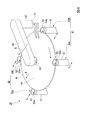
First, the substrate holding rotation mechanism 1 will be described. As shown in FIG. 3, a cleaning
図7、図8に示すように、第1駆動スピンドル50Aは駆動ローラ52(第1駆動ローラ)を有し、アイドラスピンドル50Bは従動ローラ54を有し、各第2駆動スピンドル50Cはそれぞれ駆動ローラ52(第2駆動ローラ)を有する。
基板保持回転機構1は、各駆動ローラ52および従動ローラ54の保持溝52a、54aによって基板Wを保持しながら、駆動ローラ52の回転力によって、基板Wを回転させる。
As shown in FIGS. 7 and 8, the
The substrate holding rotation mechanism 1 rotates the substrate W by the rotational force of the driving
洗浄部材駆動機構30は、図4に示すケース31の内側に設置されたシリンダ32(図4には図示せず)と、該シリンダ32により駆動される棒状の支柱部材33と、を備えている。支柱部材33は、シリンダ32の上方に突出しており、シリンダ32の駆動により上下動可能する。
図3に示すように、支柱部材33の上端には、後述する洗浄機構が取り付けられる取付部34が設けられている。一方、ケース31の両側には、該ケース31を挟んで互いに平行に配置された一対の直線状のスライドレール36が配設されている。この一対のスライドレール36の両端部に、第1移動機構10および第2移動機構20がスライド移動可能に取り付けられている。
The cleaning
As shown in FIG. 3, an
(第1移動機構)
ここで、第1移動機構10の構成を説明する。図3、4に示すように、各スライドレール36には、断面視で略U字状のスライダー12が係合されている。スライダー12は、スライドレール36が延びる方向に、このスライドレール36に対してスライド移動する。各スライダー12の下面には、略矩形の平板状に形成された連結部材13が取り付けられている。連結部材13の中央部には上下に貫通する開口部13aが設けられ、該開口部13aの内周にベアリング14が嵌合されている。ベアリング14の内輪14aには、略円柱状の軸部材15が取り付けられている。軸部材15は、開口部13a内で、ベアリング14によって連結部材13に対して回転可能に保持されている。開口部13aの上部には、開口部13a内に設置された軸部材15の上面を覆うカバー16が取り付けられている。
(1st movement mechanism)
Here, the configuration of the first moving
連結部材13の下面側には、略矩形の平板状に形成されたベース部材17が設置されている。ベース部材17は、その外形が連結部材13よりも大きく、その上面中央部が軸部材15の下端面にボルトで固定されている。これにより、ベース部材17は、図6に示すように軸部材15を中心として該軸部材15と一体に水平面内で回動するように構成されている。
A
図4に示すように、ベース部材17の上面には、連結部材13の下部を収納する略矩形状の凹部17aが形成されている。凹部17aの内周面と連結部材13の外周面との間には、僅かな寸法のクリアランスD(図6参照)が設けられている。そのため、ベース部材17は連結部材13に対して、クリアランスDで連結部材13とベース部材17とが接触しない範囲内で回動することができる。なおクリアランスDの幅寸法は、本実施形態では約2mm程度に形成されている。
As shown in FIG. 4, a substantially
図5に示すように、ベース部材17の外側(スライドレール36の延伸方向の外側)には、略L字状でその一端が下方に向かうガイド部材18が取り付けられている。ガイド部材18の内側には、下記する仕切部材3にその上端が固定された板状の係止部材19が設置されている。係止部材19の内側にはシリンダ22が取り付けられ、このシリンダ22によって進退駆動されるロッド24の先端が、フローティングジョイント21を介してガイド部材18の内側に連結されている。
As shown in FIG. 5, a
フローティングジョイント21は、詳細な図示は省略するが、それぞれがロッド24側とガイド部材18側に取り付けられる一対の連結具からなる。一方の連結具が備える球形状の突起部21aは、他方の連結具が備える球面状の凹部21b内に回転自在に係合して構成されている。これにより、ガイド部材18がロッド24に対して略全方向に揺動(回動)自在な状態で連結されているので、シリンダ22の駆動によりベース部材17と連結部材13を一体にスライドレール36に沿って往復移動させることができると共に、これらベース部材17およびガイド部材18が、係止部材19やシリンダ22とは独立して水平面内で自在に回動できるようになっている。
Although detailed illustration is omitted, the floating joint 21 is composed of a pair of connecting tools attached to the
また、図5に示すように、ガイド部材18の内面には、その先端部が係止部材19の外面に当接し、ベース部材17および連結部材13の移動を所定位置で規制する突起状のストッパー部材23が取り付けられている。なお、37はシリンダ22に取り付けられたレギュレータである。このように、第1移動機構10は、ベース部材17および連結部材13を一体にスライドレール36に沿う直線方向に往復移動させる往復移動機構と、ベース部材17を連結部材13に対して軸部材15を中心に水平面内で回動自在に設置してなる回動機構とを備えている。
すなわち、第1移動機構10は、第1スピンドル群G1を、スライドレール36に沿ってスライド移動可能かつ、軸部材15回りに回転移動可能に保持している。
Further, as shown in FIG. 5, on the inner surface of the
That is, the first moving
図4に示すように、各スピンドル50A、50Bはそれぞれ、円筒状の本体部51と、この本体部51内に挿通されたシャフト26と、を有している。なお、図示は省略するが、第2駆動スピンドル50Cの構成は第1駆動スピンドル50Aの構成と同様である。
図3に示すように、各スピンドル50A、50Bにおける本体部51の上端部には、駆動ローラ52若しくは従動ローラ54(図7参照)を取り付ける取付部51aが設けられている。この取付部51aから突出するシャフト26の上端部26aが、駆動ローラ52若しくは従動ローラ54に接続されることで、シャフト26と駆動ローラ52若しくは従動ローラ54とが一体に回転する。なお図3では、駆動ローラ52および従動ローラ54を取付部51aから取り外した状態を示している。
As shown in FIG. 4, each of the
As shown in FIG. 3, at the upper end of the
またベース部材17は、図4および図6に示すように、その両側が各スライドレール36の両外側(スライドレール36の延伸方向に直交する両外側)に突出しており、この突出した部分の上面に第1駆動スピンドル50Aおよびアイドラスピンドル50Bが立設されている。そして、図4に示すように各スピンドル50A、50Bの本体部51内に回転自在に設置されたシャフト26が、ベース部材17を貫通してその下面側に突出している。ベース部材17の下方にはモータ28が設けられており、モータ28の回転軸28aと第1駆動スピンドル50A内のシャフト26との間には、伝達ベルト29が掛け渡されている。モータ28は、伝達ベルト29を介して第1駆動スピンドル50Aのシャフト26に駆動力を入力し、このシャフト26および駆動ローラ52を一体に回転させる。
Further, as shown in FIGS. 4 and 6, both sides of the
図7に示すように、駆動ローラ52および従動ローラ54の外周面には、基板Wの外周縁に当接する保持溝52a、54aが形成されている。保持溝52a内で基板Wの周縁部を保持した状態で、各駆動ローラ52が回転することで、基板Wが回転させられる。また、従動ローラ54における保持溝54a内で、基板Wが保持された状態で、この基板Wが回転することにより、従動ローラ54とともにアイドラスピンドル50Bのシャフト26が従動して回転する。
As shown in FIG. 7, holding
図4に示すように、アイドラスピンドル50Bのシャフト26における下端部には、一対のドグ53aと、ドグ53aの回転を検知するセンサ53bと、からなる回転検出部53が設けられている。一対のドグ53aは、アイドラスピンドル50Bのシャフト26の中心軸から、その外側に向けて延びている。センサ53bとしては、投光部と受光部とを有する光学式のセンサなどを用いることができる。
As shown in FIG. 4, a
回転検出部53では、センサ53bの投光部と受光部との間にドグ53aが位置するか否かによって、センサ53bの出力信号が変わり、この出力信号が変化する時間間隔などから、ドグ53aの回転数、すなわち従動ローラ54の回転数を検出することができる。基板Wの回転数は、従動ローラ54の回転数と比例関係にあるため、従動ローラ54の回転数から基板Wの回転数を算出することができる。
以上のようにして、回転検出部53は、従動ローラ54の回転数を検出することで、基板Wの回転数を間接的に検出する。
In the
As described above, the
(第2移動機構)
第2移動機構20は、上記第1移動機構10が備えるベース部材17および連結部材13に代えて、これらの部材13、17を一体に構成したものに相当する一枚のベース部材25を備えている。また、第2移動機構20では、図示は省略するが、モータによって2本の第2駆動スピンドル50Cのシャフト26が同期して回転するように構成されている。第2移動機構20の、その他の部分の構成は、第1移動機構10と共通である。従って、第2移動機構20の図示およびその説明では、第1移動機構と共通する部分には同一の符号を付し、その詳細な説明は省略する。
(2nd moving mechanism)
The
図3に示すように第2移動機構20では、連結部材13および軸部材15に相当する部材を設けずに、スライダー12の下面をベース部材25の上面に直接取り付けており、ベース部材25をスライドレール36に沿う直線方向に往復移動させる往復移動機構のみを備えている。
すなわち、第2移動機構20は、第2スピンドル群G2をスライドレール36に沿う直線方向にスライド移動可能かつ回転移動不能に保持している。
As shown in FIG. 3, in the second moving
That is, the second moving
(ロールタイプの洗浄機構)
次に、基板保持回転機構1の上部に取り付けられる、ロールタイプの洗浄機構2Aについて説明する。図7に示す洗浄機構2Aは、基板Wを洗浄するロール洗浄部材60と、基板Wの上面に向けて洗浄液を供給する上部ノズル71と、基板Wの下面に向けて洗浄液を供給する下部ノズル72と、を備えている。
(Roll type cleaning mechanism)
Next, a roll-
ロール洗浄部材60は、基板Wの上面を洗浄する上部洗浄部材61と、基板Wの下面を0洗浄する下部洗浄部材62と、によって構成されている。各洗浄部材61,62は、基板Wの上面若しくは下面に摺接する円柱状のロールスポンジ63,64と、該ロールスポンジ63,64を回転可能に取り付けているロールスポンジ取付部材65,66と、を備えている。ロールスポンジ63、64の材質としては、多孔質のPVA製スポンジ、発泡ウレタンなどを用いることができる。これら洗浄部材61,62は、その長手方向が各スピンドル群G1,G2の間に延伸するように配置されている。
The
各ロールスポンジ63,64は、基板Wの上下面の全面に摺接可能なように、その長さが基板Wの径と同等若しくはそれ以上の寸法に形成されている。また、上部洗浄部材61は、ロールスポンジ63を上下動させ、かつ回転させる図示しない駆動機構に取り付けられている。一方、下部洗浄部材62は、詳細な図示は省略するが、支柱部材33の取付部34に取り付けられている。
Each of the
上部ノズル71および下部ノズル72は、図示しない洗浄液供給源に接続されており、基板Wの上面若しくは下面に向けて洗浄液を噴射する。洗浄液としては、超純水、アンモニア水、フッ化水素酸(フッ酸)などを用いることができる。
The
図7に示すように、ロールスポンジ63は、基板Wとの接触部において、基板Wを第2スピンドル群G2に向けて押しこむ方向に回転している。同様に、ロールスポンジ64は、基板Wとの接触部において、基板Wを第2スピンドル群G2に向けて押しこむ方向に回転している。これにより、基板Wは、ロール洗浄部材60から、第2スピンドル群G2に向けた押しこみ力(矢印F参照)を受ける。このようにして、洗浄機構2Aによって基板Wが力を受ける方向を、以下では単に押圧方向Fという。
As shown in FIG. 7, the
(ペンシルタイプの洗浄機構)
次に、ペンシルタイプの洗浄機構2Bについて説明する。図8に示す洗浄機構2Bは、回転軸67と、揺動アーム68と、ペンシル型の洗浄部材69と、を備えている。揺動アーム68は、回転軸67回りに回転させられる。洗浄部材69は、揺動アーム68の先端部における下面に取り付けられている。洗浄部材69は、上下方向に延びる円柱状に形成されている。洗浄部材69の材質としては、発泡ポリウレタン、PVAなどを用いることができる。
(Pencil type cleaning mechanism)
Next, the pencil
揺動アーム68が回転軸67周りに回転すると、揺動アーム68の先端に取り付けられたペンシル洗浄部材69は、円弧状の軌跡を描いて基板Wの上を移動する。揺動アーム68の先端は基板Wの中心まで延びているので、ペンシル洗浄部材69の移動軌跡は、基板Wの中心を通過する。また、ペンシル洗浄部材69は、基板Wの外周まで移動させられる。基板Wが回転する状態で、ペンシル洗浄部材69が上記のような軌跡で移動することで、基板Wの上面の全面が、ペンシル洗浄部材69によって洗浄される。
When the
ここで、ペンシル洗浄部材69が基板Wに接触している間における、揺動アーム68の揺動方向は、図8の矢印Rに示すように、第1スピンドル群G1から第2スピンドル群G2に向かう方向である。このように揺動アーム68が揺動することで、基板Wは、ペンシル洗浄部材69から、第2スピンドル群G2に向けた押し込み力(矢印F参照)を受ける。なお、この矢印Fの方向は、図7に示すロール洗浄部材60による押し込み力の方向と同じ方向である。すなわち、ペンシルタイプの洗浄機構2Bにおける押圧方向Fは、ロールタイプの洗浄機構2Aにおける押圧方向Fと同様の方向である。
Here, the swing direction of the
以上のように構成された基板洗浄装置は、全体が箱型のケーシング内に収納配置されており、図4および図5に示すように、スライドレール36の上面とケース31の上面が、ケーシング内に設置された板状の仕切部材3の下面側に固定されている。この仕切部材3によって、ケーシング内が下部空間と上部空間とに仕切られており、下部空間には基板保持回転機構1が収容され、上部空間には洗浄機構2A若しくは2Bが収容されている。仕切部材3により、洗浄機構2A若しくは2Bで基板を洗浄する際の洗浄液等が、下部空間内の基板保持回転機構1に達するのが防止される。なお、各スピンドル50A〜50Cや支柱部材33は、仕切部材3に設けられた開口部3a等から、仕切部材3の上方に突出している。
The entire substrate cleaning device configured as described above is housed and arranged in a box-shaped casing, and as shown in FIGS. 4 and 5, the upper surface of the
次に、以上のように構成された基板洗浄装置の作用について、図9(a)〜(d)を用いて説明する。 Next, the operation of the substrate cleaning device configured as described above will be described with reference to FIGS. 9A to 9D.
図9(a)〜(d)は、基板洗浄装置を上方から見た模式図である。また、図9(a)〜(d)に示す直線Lは、一対のスライドレール36が延在する位置を示している。以下、スライドレール36が延びる方向を単にスライド方向Lという。
基板Wを保持する際、図9(a)に示すように、スライド方向Lで基板Wを挟む両側に配置された第1スピンドル群G1および第2スピンドル群G2を、第1移動機構10および第2移動機構20によって、基板Wに向けて移動させる。このとき、第2スピンドル群G2が、第1スピンドル群G1よりも早く基板Wに接触する。第1スピンドル群G1および第2スピンドル群G2の両者が基板Wの周縁部に当接することで、基板Wが保持される。
9 (a) to 9 (d) are schematic views of the substrate cleaning apparatus as viewed from above. Further, the straight line L shown in FIGS. 9A to 9D indicates a position where the pair of slide rails 36 extend. Hereinafter, the direction in which the
When holding the substrate W, as shown in FIG. 9A, the first spindle group G1 and the second spindle group G2 arranged on both sides of the substrate W in the slide direction L are moved by the first moving
ところで、このようにして基板Wを保持する際に、第1駆動スピンドル50Aの駆動ローラ52およびアイドラスピンドル50Bの従動ローラ54が、基板Wの周縁部に互いに均等な圧力で当接しないことも考えられる。しかしながら、本実施形態では、図9(b)に示すように、駆動ローラ52若しくは従動ローラ54のうちの一方が基板Wの周縁部に当接することで、軸部材15を中心にベース部材17が回動し、他方が基板Wの周縁部に当接する。この動作により、駆動ローラ52および従動ローラ54が基板Wを保持する保持力の不均衡が是正され、各ローラが互いに均等な圧力で基板Wの周縁部に当接する。
By the way, when holding the substrate W in this way, it is also conceivable that the
次に、モータ28を駆動して各駆動スピンドル50A、50Cの駆動ローラ52を回転させ、図9(c)に示すように、基板Wを回転させる。このとき、基板Wの回転に伴って、従動ローラ54も従動して回転させられる。従動ローラ54が回転すると、アイドラスピンドル50Bのシャフト26に取り付けられたドグ53aも回転し、この回転数に応じた間隔で、センサ53bが出力するON/OFF信号が切り替わる。従って、このON/OFF信号が切り替わる時間間隔から、従動ローラ54の回転数を検出することができる。さらに、従動ローラ54は基板Wの回転に従動しているため、基板Wの回転数を間接的に算出することができる。
Next, the
基板Wが回転を開始すると、ノズル71、72が基板Wに向けて洗浄液を噴射しながら、ロール洗浄部材60若しくはペンシル洗浄部材69が基板Wに押し付けられ、基板Wが洗浄される。このとき、図9(d)に示すように、基板Wには、ロール洗浄部材60若しくはペンシル洗浄部材69から受ける第2スピンドル群G2に向けた押圧方向Fの押し込み力が作用する。そして、第2スピンドル群G2が有する複数の駆動ローラ52は、いずれも基板Wに回転力を与えるものである。従って、例えば第2スピンドル群G2にアイドラスピンドル50Bが含まれている場合と比較して、基板Wに、確実に回転力を付与することができる。
When the substrate W starts rotating, the
また、基板Wに回転させられる従動ローラ54が、押圧方向Fの反対側に位置している。これにより、例えば洗浄部材60、69によって基板Wが力を受ける方向に従動ローラ54が位置する場合と比較して、洗浄部材60、69による押し付け力を、基板Wが駆動ローラ52に押し付けられる力として有効に利用することができる。従って、駆動ローラ52によって基板Wをより確実に回転させることができる。
Further, the driven
また、例えば前記特許文献1の構成に対して従動ローラ54を追加する場合と比較して、基板Wに接触するローラの数を少なくして、これらのローラに付着した汚れによって基板Wが汚染されてしまう現象の発生を抑えることができる。
さらに、従動ローラ54の基板Wへの押し付け力を、駆動ローラ52の基板への押し付け力と同等にしたとしても、基板Wに加えられる力のバランスが上記特許文献1の構成と比較して悪化しないため、基板Wの変形などを抑えながら、強い力で従動ローラ54を基板Wに押し付けて、従動ローラ54と基板Wとの間で生じるスリップを抑止することができる。
Further, for example, as compared with the case where the driven
Further, even if the pressing force of the driven
また、第1移動機構10が第1スピンドル群G1をスライド移動可能かつ回転移動可能に保持し、第2移動機構20が第2スピンドル群G2をスライド移動可能かつ回転移動不能に保持している。この構成により、第1スピンドル群G1と第2スピンドル群G2との間で基板Wを挟持した際に、第1スピンドル群G1が回転移動することで、各スピンドル50A〜50Cによる基板Wの保持力のバランスを均一化することができる。
Further, the first moving
以上説明したように、本実施形態の基板洗浄装置によれば、回転検出部53が従動ローラ54の回転数を検出することで基板Wの回転数を精度よく測定しつつ、基板Wの洗浄の品質を安定させることが可能となる。
さらに、本実施形態の基板処理装置200によれば、研磨部103で研磨された基板Wを基板洗浄装置201A、201B、202A、202Bで洗浄する際に、基板Wの回転数を精度よく測定しつつ、駆動ローラ52や従動ローラ54の汚れが基板Wに再度付着することなどを抑えて、処理された基板Wの品質を安定させることができる。
As described above, according to the substrate cleaning apparatus of the present embodiment, the
Further, according to the substrate processing apparatus 200 of the present embodiment, when the substrate W polished by the polishing
なお、本発明の技術的範囲は前記実施の形態に限定されるものではなく、本発明の趣旨を逸脱しない範囲において種々の変更を加えることが可能である。 The technical scope of the present invention is not limited to the above-described embodiment, and various modifications can be made without departing from the spirit of the present invention.
例えば、前記実施形態では、第1スピンドル群G1および第2スピンドル群G2が、それぞれ2本のスピンドルを有していたが、これらのスピンドル群G1、G2に含まれるスピンドルの本数は適宜変更してもよい。 For example, in the above embodiment, the first spindle group G1 and the second spindle group G2 each have two spindles, but the number of spindles included in these spindle groups G1 and G2 is appropriately changed. May be good.
また、前記実施形態では、ドグ53aおよびセンサ53bによって従動ローラ54の回転数を検出したが、他の形態の回転検出部によって、従動ローラ54の回転数を検出してもよい。例えば、非接触式速度計などによって、アイドラスピンドル50Bのシャフト26の周速を測定することで、従動ローラ54の回転数を検出してもよい。この場合、非接触式速度計が回転検出部に相当する。
Further, in the above-described embodiment, the rotation speed of the driven
また、従動ローラ54が回転する際の慣性モーメントを、駆動ローラ52が回転する際の慣性モーメントよりも小さくしてもよい。この場合、基板Wの回転に伴って従動ローラ54が回転しやすくなり、従動ローラ54と基板Wとの間のスリップが生じにくくなる。これにより、より精度よく基板Wの回転数を検出することが可能となる。
Further, the moment of inertia when the driven
なお、従動ローラ54が回転する際の慣性モーメントを小さくする方法としては、アイドラスピンドル50Bにおけるシャフト26の外径を、他のスピンドル50A、50Cにおけるシャフト26の外径より小さくした構成が考えられる。あるいは、アイドラスピンドル50Bのシャフト26の材質として、他のシャフト26の材質よりも密度の軽いものを採用することも考えられる。これらの形態によれば、消耗品である駆動ローラ52および従動ローラ54を同一の種類の部品としながら、従動ローラ54が回転する際の慣性モーメントを小さくすることができる。つまり、駆動ローラ52および従動ローラ54の部品を共通化して、コストダウンやメンテナンス性の向上などを図ることができる。
As a method of reducing the moment of inertia when the driven
また、前記実施形態では、各スピンドル50A〜50Cが上下方向に延び、基板Wが水平に保持される基板保持回転機構1について説明したが、基板Wが垂直に保持される、いわゆる縦置き型の基板保持回転機構を採用してもよい。この場合、前記実施形態で説明した基板保持回転機構1の全体が、90°倒されたような形態を採用することができる。
Further, in the above embodiment, the substrate holding rotation mechanism 1 in which the
また、前記実施形態の基板処理装置200は、ロールタイプの基板洗浄装置およびペンシルタイプの基板洗浄装置の両者を備えていたが、どちらか一方のタイプの基板洗浄装置を備えた基板処理装置200を採用してもよい。また、基板処理装置200が備える基板洗浄装置の数および配置は、適宜変更することができる。 Further, the substrate processing device 200 of the above-described embodiment includes both a roll type substrate cleaning device and a pencil type substrate cleaning device, but the substrate processing device 200 including either one type of substrate cleaning device is provided. It may be adopted. Further, the number and arrangement of the substrate cleaning devices included in the substrate processing device 200 can be appropriately changed.
その他、本発明の趣旨を逸脱しない範囲で、上記した実施の形態における構成要素を周知の構成要素に置き換えることは適宜可能であり、また、上記した実施形態や変形例を適宜組み合わせてもよい。 In addition, it is possible to replace the components in the above-described embodiment with well-known components as appropriate without departing from the spirit of the present invention, and the above-described embodiments and modifications may be appropriately combined.
1…基板保持回転機構 2A、2B…洗浄機構 10…第1移動機構 20…第2移動機構 50A…第1駆動スピンドル 50B…アイドラスピンドル 50C…第2駆動スピンドル 52…駆動ローラ 53…回転検出部 54…従動ローラ 103…研磨部 200…基板処理装置 201A、201B、202A、202B…基板洗浄装置 F…押圧方向 G1…第1スピンドル群 G2…第2スピンドル群
1 ... Board holding
Claims (7)
前記基板を回転させる第2駆動ローラをそれぞれ有する複数の第2駆動スピンドルを含む第2スピンドル群と、
前記第1駆動ローラおよび複数の前記第2駆動ローラによって回転させられる前記基板に洗浄部材を接触させて前記基板を洗浄する洗浄機構と、
前記従動ローラの回転数を検出する回転検出部と、
前記第1スピンドル群をスライド移動可能かつ回転移動可能に保持する第1移動機構と、
前記第2スピンドル群をスライド移動可能かつ回転移動不能に保持する第2移動機構と、を備え、
前記洗浄部材は、前記基板と接触している間において回転または揺動することで、前記基板を押し込む押し込み力を発生させ、
前記押し込み力は、前記基板を前記第1スピンドル群から前記第2スピンドル群に向けて押し込む方向に成分を有する、基板洗浄装置。 A first spindle group including a first drive spindle having a first drive roller for rotating a substrate and an idler spindle having a driven roller rotated by the substrate.
A second spindle group including a plurality of second drive spindles each having a second drive roller for rotating the substrate, and a second spindle group.
A cleaning mechanism that cleans the substrate by bringing the cleaning member into contact with the substrate rotated by the first drive roller and the plurality of second drive rollers.
A rotation detection unit that detects the rotation speed of the driven roller, and
A first moving mechanism that holds the first spindle group so that it can be slidably and rotationally moved.
A second moving mechanism that holds the second spindle group slidably and non-rotatably movable is provided.
The cleaning member rotates or swings while in contact with the substrate to generate a pushing force for pushing the substrate.
A substrate cleaning device having a component in a direction in which the pushing force pushes the substrate from the first spindle group toward the second spindle group .
回転する前記基板に接触することで回転する従動ローラと、
回転する前記基板に洗浄部材を接触させて前記基板を洗浄する洗浄機構と、
前記従動ローラの回転数を検出する回転検出部と、
前記第1駆動ローラおよび前記従動ローラをスライド移動可能かつ回転移動可能に保持する第1移動機構と、
複数の前記第2駆動ローラをスライド移動可能かつ回転移動不能に保持する第2移動機構と、を備え、
前記洗浄部材は、前記基板と接触している間において回転または揺動することで、前記基板を押し込む押し込み力を発生させ、
前記押し込み力は、前記基板を、前記第1駆動ローラおよび前記従動ローラから前記複数の第2駆動ローラに向けて押し込む方向に成分を有し、
前記回転検出部は、前記従動ローラとともに回転するドグと、投光部および受光部を有するセンサと、を備え、前記投光部と前記受光部との間に前記ドグが位置するか否かによって変化する前記センサの出力信号に基づいて、前記ドグの回転数を検出するように構成されている、基板洗浄装置。 A first drive roller for rotating the substrate and a plurality of second drive rollers,
A driven roller that rotates by contacting the rotating substrate,
A cleaning mechanism that cleans the substrate by bringing the cleaning member into contact with the rotating substrate.
A rotation detection unit that detects the rotation speed of the driven roller, and
A first moving mechanism that holds the first driving roller and the driven roller so that they can slide and rotate.
A second moving mechanism for holding a plurality of the second driving rollers so as to be slidable and non-rotatable is provided.
The cleaning member rotates or swings while in contact with the substrate to generate a pushing force for pushing the substrate.
The pushing force has a component in a direction of pushing the substrate from the first driving roller and the driven roller toward the plurality of second driving rollers.
The rotation detection unit includes a dog that rotates together with the driven roller, a sensor having a light emitting unit and a light receiving unit, and depending on whether or not the dog is located between the light emitting unit and the light receiving unit. A substrate cleaning device configured to detect the rotation speed of the dog based on a changing output signal of the sensor.
前記ロール洗浄部材は前記基板との接触部において前記基板を複数の前記第2駆動ローラに向けて押し込む方向に回転するように構成されている、請求項1から請求項3のいずれか1項に記載の基板洗浄装置。 The cleaning member is a roll cleaning member that comes into contact with the rotating substrate.
The roll cleaning member is configured to rotate in a direction of pushing the substrate toward the plurality of second drive rollers at a contact portion with the substrate, according to any one of claims 1 to 3. The substrate cleaning device described.
前記洗浄機構は、該ペンシル洗浄部材が前記基板の中心と外周とを結ぶ所定の軌跡を揺動するように該ペンシル洗浄部材が取り付けられた揺動アームを有し、
前記揺動アームは、前記ペンシル洗浄部材が前記基板と接触している間において、前記第1駆動ローラおよび前記従動ローラから複数の前記第2駆動ローラに向かう方向に揺動する、請求項1から請求項3のいずれか1項に記載の基板洗浄装置。 The cleaning member is a pencil cleaning member that comes into contact with the rotating substrate .
The cleaning mechanism includes a swinging arm to the pencil cleaning member is attached to the pencil cleaning member is swung a predetermined trajectory connecting the center and the outer periphery of the substrate,
According to claim 1, the swing arm swings in a direction from the first drive roller and the driven roller toward a plurality of the second drive rollers while the pencil cleaning member is in contact with the substrate. The substrate cleaning apparatus according to any one of claims 3 .
前記第1洗浄室及び前記第2洗浄室はそれぞれ、請求項1から請求項5のいずれか1項に記載の基板洗浄装置を含む、基板処理装置。 A substrate processing apparatus including a cleaning unit having a first cleaning chamber, a first transport chamber, a second cleaning chamber, a second transport chamber, and a drying chamber.
Each of the first cleaning chamber and the second cleaning chamber is a substrate processing apparatus including the substrate cleaning apparatus according to any one of claims 1 to 5 .
請求項1から請求項5のいずれか1項に記載の基板洗浄装置を有する洗浄部と、を備える基板処理装置。 A polishing part that polishes the substrate and
A substrate processing apparatus including a cleaning unit having the substrate cleaning apparatus according to any one of claims 1 to 5 .
Priority Applications (7)
| Application Number | Priority Date | Filing Date | Title |
|---|---|---|---|
| JP2017097621A JP6792512B2 (en) | 2017-05-16 | 2017-05-16 | Substrate cleaning equipment and substrate processing equipment |
| KR1020180052454A KR102494451B1 (en) | 2017-05-16 | 2018-05-08 | Substrate cleaning apparatus, substrate processing apparatus, and method of cleaning substrate |
| CN201810450204.3A CN108878314B (en) | 2017-05-16 | 2018-05-11 | Substrate cleaning apparatus and substrate processing apparatus |
| US15/978,320 US10741423B2 (en) | 2017-05-16 | 2018-05-14 | Substrate cleaning apparatus, substrate processing apparatus, and method of cleaning substrate |
| SG10201804063YA SG10201804063YA (en) | 2017-05-16 | 2018-05-14 | Substrate cleaning apparatus, substrate processing apparatus, and method of cleaning substrate |
| TW107116219A TWI770175B (en) | 2017-05-16 | 2018-05-14 | Substrate cleaning apparatus, and substrate processing apparatus |
| US16/919,788 US11532491B2 (en) | 2017-05-16 | 2020-07-02 | Substrate cleaning apparatus, substrate processing apparatus, and method of cleaning substrate |
Applications Claiming Priority (1)
| Application Number | Priority Date | Filing Date | Title |
|---|---|---|---|
| JP2017097621A JP6792512B2 (en) | 2017-05-16 | 2017-05-16 | Substrate cleaning equipment and substrate processing equipment |
Publications (3)
| Publication Number | Publication Date |
|---|---|
| JP2018195680A JP2018195680A (en) | 2018-12-06 |
| JP2018195680A5 JP2018195680A5 (en) | 2019-12-12 |
| JP6792512B2 true JP6792512B2 (en) | 2020-11-25 |
Family
ID=64272527
Family Applications (1)
| Application Number | Title | Priority Date | Filing Date |
|---|---|---|---|
| JP2017097621A Active JP6792512B2 (en) | 2017-05-16 | 2017-05-16 | Substrate cleaning equipment and substrate processing equipment |
Country Status (6)
| Country | Link |
|---|---|
| US (2) | US10741423B2 (en) |
| JP (1) | JP6792512B2 (en) |
| KR (1) | KR102494451B1 (en) |
| CN (1) | CN108878314B (en) |
| SG (1) | SG10201804063YA (en) |
| TW (1) | TWI770175B (en) |
Families Citing this family (10)
| Publication number | Priority date | Publication date | Assignee | Title |
|---|---|---|---|---|
| JP6792512B2 (en) * | 2017-05-16 | 2020-11-25 | 株式会社荏原製作所 | Substrate cleaning equipment and substrate processing equipment |
| JP7356811B2 (en) * | 2019-04-02 | 2023-10-05 | 株式会社荏原製作所 | Substrate support device and method for controlling the substrate support device |
| CN110148573B (en) * | 2019-04-17 | 2020-12-04 | 湖州达立智能设备制造有限公司 | Wafer lifting device of semiconductor equipment process chamber |
| KR102428923B1 (en) * | 2020-01-22 | 2022-08-04 | 주식회사 씨티에스 | CMP apparatus |
| KR20220036517A (en) * | 2020-09-16 | 2022-03-23 | 삼성전자주식회사 | Wafer cleaning apparatus and wafer cleaning method using the same |
| KR102590328B1 (en) * | 2020-12-24 | 2023-10-16 | 세메스 주식회사 | Substrate gripping apparatus and liquid processing apparatus, and substrate processing equipment including the same |
| CN112820627B (en) * | 2020-12-30 | 2022-10-18 | 江苏亚电科技有限公司 | Efficient wafer cleaning method |
| CN113607980B (en) * | 2021-10-08 | 2021-11-30 | 南通优睿半导体有限公司 | Selection testing arrangement of semiconductor device material research and development |
| CN113621786B (en) * | 2021-10-13 | 2021-12-14 | 南通锦发电缆有限公司 | Annealing device for manufacturing wires and cables |
| KR20230140641A (en) * | 2022-03-29 | 2023-10-10 | 삼성디스플레이 주식회사 | Imprint apparatus |
Family Cites Families (19)
| Publication number | Priority date | Publication date | Assignee | Title |
|---|---|---|---|---|
| JP2582976B2 (en) * | 1991-12-19 | 1997-02-19 | 大日本スクリーン製造株式会社 | Substrate presence / absence detection device in rotary substrate processing equipment |
| JPH10289889A (en) | 1997-04-16 | 1998-10-27 | Dainippon Screen Mfg Co Ltd | Substrate treatment apparatus |
| JP3964517B2 (en) * | 1997-10-31 | 2007-08-22 | 芝浦メカトロニクス株式会社 | Cleaning device and method |
| JP3343503B2 (en) * | 1997-12-12 | 2002-11-11 | 東京エレクトロン株式会社 | Cleaning equipment |
| JP2001038614A (en) * | 1999-07-26 | 2001-02-13 | Ebara Corp | Grinding device |
| US7685667B2 (en) * | 2005-06-14 | 2010-03-30 | Taiwan Semiconductor Manufacturing Co., Ltd. | Post-CMP cleaning system |
| US7938130B2 (en) * | 2006-03-31 | 2011-05-10 | Ebara Corporation | Substrate holding rotating mechanism, and substrate processing apparatus |
| JP4937807B2 (en) * | 2006-03-31 | 2012-05-23 | 株式会社荏原製作所 | Substrate holding and rotating mechanism, substrate processing apparatus |
| US20080011325A1 (en) * | 2006-06-05 | 2008-01-17 | Olgado Donald J | Methods and apparatus for supporting a substrate in a horizontal orientation during cleaning |
| KR100786627B1 (en) | 2006-07-24 | 2007-12-21 | 두산메카텍 주식회사 | Apparatus for sensing rotation of wafer |
| US7823241B2 (en) | 2007-03-22 | 2010-11-02 | Taiwan Semiconductor Manufacturing Co., Ltd. | System for cleaning a wafer |
| JP2010169606A (en) * | 2009-01-26 | 2010-08-05 | Mitsuboshi Belting Ltd | Endurance testing machine for power transmission mechanism |
| JP2015220402A (en) * | 2014-05-20 | 2015-12-07 | 株式会社荏原製作所 | Substrate cleaning device and method performed by substrate cleaning device |
| KR102004109B1 (en) * | 2014-10-31 | 2019-07-25 | 가부시키가이샤 에바라 세이사꾸쇼 | Substrate cleaning device and substrate cleaning method |
| SG10201601095UA (en) | 2015-02-18 | 2016-09-29 | Ebara Corp | Substrate cleaning apparatus, substrate cleaning method, and substrate processing apparatus |
| JP6491908B2 (en) * | 2015-03-09 | 2019-03-27 | 株式会社荏原製作所 | Substrate cleaning apparatus, substrate cleaning method, and substrate processing apparatus |
| JP6491903B2 (en) * | 2015-02-19 | 2019-03-27 | 株式会社荏原製作所 | Substrate cleaning apparatus and method |
| JP6328577B2 (en) * | 2015-02-24 | 2018-05-23 | 株式会社荏原製作所 | Load measuring device and load measuring method |
| JP6792512B2 (en) * | 2017-05-16 | 2020-11-25 | 株式会社荏原製作所 | Substrate cleaning equipment and substrate processing equipment |
-
2017
- 2017-05-16 JP JP2017097621A patent/JP6792512B2/en active Active
-
2018
- 2018-05-08 KR KR1020180052454A patent/KR102494451B1/en active IP Right Grant
- 2018-05-11 CN CN201810450204.3A patent/CN108878314B/en active Active
- 2018-05-14 TW TW107116219A patent/TWI770175B/en active
- 2018-05-14 US US15/978,320 patent/US10741423B2/en active Active
- 2018-05-14 SG SG10201804063YA patent/SG10201804063YA/en unknown
-
2020
- 2020-07-02 US US16/919,788 patent/US11532491B2/en active Active
Also Published As
| Publication number | Publication date |
|---|---|
| KR20180125887A (en) | 2018-11-26 |
| US20200335363A1 (en) | 2020-10-22 |
| SG10201804063YA (en) | 2018-12-28 |
| US10741423B2 (en) | 2020-08-11 |
| CN108878314B (en) | 2023-09-29 |
| US20180337072A1 (en) | 2018-11-22 |
| KR102494451B1 (en) | 2023-02-01 |
| CN108878314A (en) | 2018-11-23 |
| TWI770175B (en) | 2022-07-11 |
| TW201902585A (en) | 2019-01-16 |
| US11532491B2 (en) | 2022-12-20 |
| JP2018195680A (en) | 2018-12-06 |
Similar Documents
| Publication | Publication Date | Title |
|---|---|---|
| JP6792512B2 (en) | Substrate cleaning equipment and substrate processing equipment | |
| KR102263992B1 (en) | Substrate processing apparatus and processing method | |
| JP4763755B2 (en) | Polishing device | |
| KR20210030331A (en) | Substrate processing apparatus | |
| US9144881B2 (en) | Polishing apparatus and polishing method | |
| JP5188952B2 (en) | Substrate processing equipment | |
| US8087419B2 (en) | Substrate holding rotating mechanism, and substrate processing apparatus | |
| KR20160030855A (en) | Processing module, processing apparatus and processing method | |
| CN105164793B (en) | It is used for the design of disk/pad cleaning of the chip and Waffer edge/oblique angle cleaning module chemically-mechanicapolish polished for utilizing | |
| JP6710129B2 (en) | Substrate cleaning apparatus and substrate cleaning method | |
| TWI433754B (en) | Grinding device | |
| KR102307209B1 (en) | Buff processing device and substrate processing device | |
| JP7165104B2 (en) | Attachment/detachment jig for cleaning member | |
| JP2008132592A (en) | Polishing device and polishing method | |
| JP6426965B2 (en) | Processing component, processing module, and processing method | |
| WO2023037716A1 (en) | Substrate cleaning device, substrate processing device, and maintenance method for substrate cleaning device | |
| JP6353266B2 (en) | Cooling device and substrate processing apparatus | |
| KR20240052946A (en) | Substrate cleaning device, substrate processing device, and substrate cleaning device maintenance method | |
| JP6412385B2 (en) | Conditioning unit, buff processing module, substrate processing apparatus, and dress rinse method | |
| JP2022124016A (en) | Substrate cleaning apparatus, abnormality determination method of substrate cleaning apparatus, and abnormality determination program of substrate cleaning apparatus |
Legal Events
| Date | Code | Title | Description |
|---|---|---|---|
| A521 | Request for written amendment filed |
Free format text: JAPANESE INTERMEDIATE CODE: A523 Effective date: 20191029 |
|
| A621 | Written request for application examination |
Free format text: JAPANESE INTERMEDIATE CODE: A621 Effective date: 20191029 |
|
| A977 | Report on retrieval |
Free format text: JAPANESE INTERMEDIATE CODE: A971007 Effective date: 20200722 |
|
| A131 | Notification of reasons for refusal |
Free format text: JAPANESE INTERMEDIATE CODE: A131 Effective date: 20200818 |
|
| A521 | Request for written amendment filed |
Free format text: JAPANESE INTERMEDIATE CODE: A523 Effective date: 20201006 |
|
| TRDD | Decision of grant or rejection written | ||
| A01 | Written decision to grant a patent or to grant a registration (utility model) |
Free format text: JAPANESE INTERMEDIATE CODE: A01 Effective date: 20201027 |
|
| A61 | First payment of annual fees (during grant procedure) |
Free format text: JAPANESE INTERMEDIATE CODE: A61 Effective date: 20201106 |
|
| R150 | Certificate of patent or registration of utility model |
Ref document number: 6792512 Country of ref document: JP Free format text: JAPANESE INTERMEDIATE CODE: R150 |
|
| R250 | Receipt of annual fees |
Free format text: JAPANESE INTERMEDIATE CODE: R250 |