JP6491903B2 - Substrate cleaning apparatus and method - Google Patents
Substrate cleaning apparatus and method Download PDFInfo
- Publication number
- JP6491903B2 JP6491903B2 JP2015030489A JP2015030489A JP6491903B2 JP 6491903 B2 JP6491903 B2 JP 6491903B2 JP 2015030489 A JP2015030489 A JP 2015030489A JP 2015030489 A JP2015030489 A JP 2015030489A JP 6491903 B2 JP6491903 B2 JP 6491903B2
- Authority
- JP
- Japan
- Prior art keywords
- substrate
- roller
- cleaning
- slip
- rotating
- Prior art date
- Legal status (The legal status is an assumption and is not a legal conclusion. Google has not performed a legal analysis and makes no representation as to the accuracy of the status listed.)
- Active
Links
- 239000000758 substrate Substances 0.000 title claims description 232
- 238000004140 cleaning Methods 0.000 title claims description 97
- 238000000034 method Methods 0.000 title claims description 23
- 238000003825 pressing Methods 0.000 claims description 51
- 230000002093 peripheral effect Effects 0.000 claims description 28
- 230000003287 optical effect Effects 0.000 claims description 17
- 238000001514 detection method Methods 0.000 claims description 11
- 239000007788 liquid Substances 0.000 claims description 11
- 238000012544 monitoring process Methods 0.000 claims description 5
- 239000004065 semiconductor Substances 0.000 description 4
- 230000001133 acceleration Effects 0.000 description 2
- 238000010586 diagram Methods 0.000 description 2
- 230000015572 biosynthetic process Effects 0.000 description 1
- 230000000694 effects Effects 0.000 description 1
- 238000005530 etching Methods 0.000 description 1
- 238000005755 formation reaction Methods 0.000 description 1
- 238000004519 manufacturing process Methods 0.000 description 1
- 239000000463 material Substances 0.000 description 1
- 239000002245 particle Substances 0.000 description 1
- 238000005498 polishing Methods 0.000 description 1
- 239000000126 substance Substances 0.000 description 1
Images


Landscapes
- Cleaning Or Drying Semiconductors (AREA)
Description
本発明は、半導体ウェハ等の基板の周縁部を複数のローラで保持しつつローラを回転駆動することにより基板を回転させ、回転する基板に洗浄部材を接触させつつ基板に洗浄液を供給して基板を洗浄する基板洗浄装置および方法に関するものである。 The present invention rotates a substrate by rotating the roller while holding the peripheral portion of the substrate such as a semiconductor wafer with a plurality of rollers, and supplies a cleaning liquid to the substrate while bringing a cleaning member into contact with the rotating substrate. The present invention relates to an apparatus and method for cleaning a substrate.
半導体デバイスの製造工程においては、半導体ウェハ等の基板の表面に成膜、エッチング、研磨などの各種処理が施される。これら各種処理のためには、基板の表面を清浄に保つ必要があるので、基板の洗浄処理が行われる。基板の洗浄処理には、基板の周縁部を複数のローラによって保持しつつローラを回転駆動することにより基板を回転させ、回転する基板に洗浄部材を押し当てて洗浄する洗浄機が広く用いられている。 In the manufacturing process of a semiconductor device, various processes such as film formation, etching, and polishing are performed on the surface of a substrate such as a semiconductor wafer. For these various processes, it is necessary to keep the surface of the substrate clean, so that the substrate is cleaned. For cleaning the substrate, a cleaning machine is widely used in which the substrate is rotated by rotating the roller while holding the peripheral portion of the substrate by a plurality of rollers, and the cleaning member is pressed against the rotating substrate for cleaning. Yes.
上述したように、基板を複数のローラで挟み回転させる洗浄機においては、洗浄部材によって基板の表面に所定の圧力を加えつつ基板の表面を擦ることにより、基板の表面の汚れ(パーティクル等)を落とすようにしているため、基板とローラとの間にスリップが発生して基板の回転速度が設定回転速度より低下する場合がある。 As described above, in a cleaning machine that sandwiches and rotates a substrate with a plurality of rollers, the substrate surface is rubbed against the substrate surface while applying a predetermined pressure to the substrate surface by the cleaning member to remove dirt (particles, etc.) As a result, the slip may occur between the substrate and the roller, and the rotation speed of the substrate may be lower than the set rotation speed.
基板を複数のローラで挟み回転させる洗浄機において、基板とローラとの間にスリップが発生するかどうかは、ローラの接触部の摩耗の他、洗浄部材の回転速度および押付力、薬液の種類、基板周縁部の材料により変わる。基板とローラとの間のスリップを検知する方法はいくつか知られているが、従来はスリップが検知された後、ローラの接触部の交換やローラの押し付け力(クランプ力)の調整をマニュアルで行っている。種々の条件が変わるたびにそのような作業を行うことはきわめて煩雑であった。また、ローラのクランプ力を強めた状態で処理を継続すると、ローラの接触部の摩耗が進み、寿命が短くなる問題がある。 In a cleaning machine that rotates a substrate between a plurality of rollers, whether or not slip occurs between the substrate and the roller depends on the wear of the roller contact portion, the rotation speed and pressing force of the cleaning member, the type of chemical, It depends on the material of the peripheral edge of the substrate. Several methods are known to detect slip between the substrate and the roller. Conventionally, after the slip is detected, it is necessary to manually change the contact part of the roller and adjust the pressing force (clamping force) of the roller. Is going. It has been extremely cumbersome to perform such work every time various conditions change. Further, if the processing is continued with the roller clamping force strengthened, there is a problem that the wear of the contact portion of the roller advances and the life is shortened.
本発明は、上述の事情に鑑みなされたもので、洗浄中に基板とローラとの間に発生するスリップの有無を監視し、スリップが発生した場合に基板に対するローラの押し付け力を自動的に調整することができる基板洗浄装置および方法を提供することを目的とする。 The present invention has been made in view of the above circumstances, and monitors the presence or absence of slip generated between the substrate and the roller during cleaning, and automatically adjusts the pressing force of the roller against the substrate when the slip occurs. It is an object of the present invention to provide a substrate cleaning apparatus and method that can be used.
上述の目的を達成するため、本発明の基板洗浄装置は、基板の周縁部を複数のローラで保持しつつローラを回転駆動することにより基板を回転させ、回転する基板に洗浄部材を接触させつつ、基板に洗浄液を供給して基板を洗浄する基板洗浄装置において、基板の回転速度が設定された回転速度より低下する状態になる基板とローラとの間に発生するスリップを検知するスリップ検知手段と、前記ローラを所定の押し付け力で基板に押し付けるローラ押し付け機構と、前記スリップ検知手段が基板とローラとの間のスリップを検知した際に、前記ローラ押し付け機構による押し付け力を増加させる制御部とを備えたことを特徴とする。
本発明によれば、基板とローラとの間のスリップを検知した際に、基板へのローラの押し付け力(クランプ力)を増加させることにより、基板とローラとの間のスリップを解消することができる。したがって、基板の回転速度を直ちに設定回転速度に復帰させることができる。
In order to achieve the above-mentioned object, the substrate cleaning apparatus of the present invention rotates the substrate by rotating the roller while holding the peripheral edge of the substrate with a plurality of rollers, and makes the cleaning member contact the rotating substrate. A substrate detecting apparatus for supplying a cleaning liquid to the substrate to clean the substrate; and a slip detecting means for detecting a slip generated between the substrate and the roller that is in a state where the rotation speed of the substrate is lower than a set rotation speed; A roller pressing mechanism that presses the roller against the substrate with a predetermined pressing force, and a controller that increases the pressing force by the roller pressing mechanism when the slip detection means detects a slip between the substrate and the roller. It is characterized by having.
According to the present invention, when the slip between the substrate and the roller is detected, the slip between the substrate and the roller can be eliminated by increasing the pressing force (clamping force) of the roller against the substrate. it can. Therefore, the rotation speed of the substrate can be immediately returned to the set rotation speed.
本発明の好ましい態様によれば、前記スリップ検知手段は、基板の周縁部にあるノッチが前記ローラに当たることでローラに発生する振動を検出する振動センサからなることを特徴とする。
本発明の好ましい態様によれば、前記スリップ検知手段は、基板の周縁部にあるノッチを検出可能な光センサからなることを特徴とする。
本発明の好ましい態様によれば、前記スリップ検知手段は、基板の周縁部に接触して回転する従動ローラと、従動ローラの回転速度を測定する速度センサからなることを特徴とする。
本発明の好ましい態様によれば、前記ローラ押し付け機構は、エアシリンダまたは電動シリンダからなることを特徴とする。
According to a preferred aspect of the present invention, the slip detection means includes a vibration sensor that detects vibration generated in the roller when a notch in a peripheral portion of the substrate hits the roller.
According to a preferred aspect of the present invention, the slip detection means comprises an optical sensor capable of detecting a notch in the peripheral edge of the substrate.
According to a preferred aspect of the present invention, the slip detection means comprises a driven roller that rotates in contact with the peripheral edge of the substrate, and a speed sensor that measures the rotational speed of the driven roller.
According to a preferred aspect of the present invention, the roller pressing mechanism includes an air cylinder or an electric cylinder.
本発明の好ましい態様によれば、前記制御部は、前記スリップ検知手段から受信した信号が所定の閾値を下回った時に前記ローラ押し付け機構による押し付け力を増加させることを特徴とする。
本発明によれば、スリップ検知手段の信号が所定の閾値より低下したときに、基板とローラとの間にスリップが発生したと判定し、基板へのローラの押し付け力(クランプ力)を増加させる。これにより、スリップを解消することができる。
According to a preferred aspect of the present invention, the control unit increases the pressing force by the roller pressing mechanism when a signal received from the slip detection unit falls below a predetermined threshold value.
According to the present invention, when the signal of the slip detection means falls below a predetermined threshold value, it is determined that slip has occurred between the substrate and the roller, and the pressing force (clamping force) of the roller against the substrate is increased. . Thereby, slip can be eliminated.
本発明の基板洗浄方法は、基板の周縁部を複数のローラで保持しつつローラを回転駆動することにより基板を回転させ、回転する基板に洗浄部材を接触させつつ基板に洗浄液を供給して基板を洗浄する基板洗浄方法において、複数の回転するローラを所定の押し付け力で基板に押し付けて基板を設定された回転速度で回転させ、回転する基板に洗浄部材を接触させて洗浄し、前記洗浄中に、基板の回転速度が前記設定された回転速度より低下する状態になる基板とローラとの間に発生するスリップの有無を監視し、前記スリップが発生した際に、基板に対する前記ローラの押し付け力を増加させて基板の洗浄を継続することを特徴とする。
本発明によれば、基板とローラとの間のスリップを検知した際に、基板へのローラの押し付け力(クランプ力)を増加させることにより、基板とローラとの間のスリップを解消することができる。したがって、基板の回転速度を直ちに設定回転速度に復帰させることができる。
In the substrate cleaning method of the present invention, the substrate is rotated by rotating the roller while holding the peripheral edge of the substrate with a plurality of rollers, and the cleaning liquid is supplied to the substrate while bringing the cleaning member into contact with the rotating substrate. In the substrate cleaning method for cleaning the substrate, a plurality of rotating rollers are pressed against the substrate with a predetermined pressing force, the substrate is rotated at a set rotation speed, the cleaning member is brought into contact with the rotating substrate, and the substrate is cleaned. In addition, the presence or absence of slip generated between the substrate and the roller where the rotation speed of the substrate is lower than the set rotation speed is monitored, and the pressing force of the roller against the substrate when the slip occurs In this case, the cleaning of the substrate is continued.
According to the present invention, when the slip between the substrate and the roller is detected, the slip between the substrate and the roller can be eliminated by increasing the pressing force (clamping force) of the roller against the substrate. it can. Therefore, the rotation speed of the substrate can be immediately returned to the set rotation speed.
本発明の好ましい態様は、基板の周縁部にあるノッチが前記ローラに当たることでローラに発生する振動を検出する振動センサによって前記スリップを検知することを特徴とする。
本発明の好ましい態様は、基板の周縁部にあるノッチを検出可能な光センサによって基板の回転を監視することで、前記スリップを検知することを特徴とする。
本発明の好ましい態様は、基板の周縁部に接触して回転する従動ローラの回転を速度センサによって監視することで、前記スリップを検知することを特徴とする。
In a preferred aspect of the present invention, the slip is detected by a vibration sensor that detects vibration generated in the roller when a notch in a peripheral edge of the substrate hits the roller.
In a preferred aspect of the present invention, the slip is detected by monitoring the rotation of the substrate by an optical sensor capable of detecting a notch at the peripheral edge of the substrate.
In a preferred aspect of the present invention, the slip is detected by monitoring the rotation of a driven roller that rotates in contact with the peripheral edge of the substrate by a speed sensor.
本発明の基板洗浄装置の調整方法の実施形態によれば、基板の周縁部を複数のローラで保持しつつローラを回転駆動することにより基板を回転させ、回転する基板に洗浄部材を接触させつつ基板に洗浄液を供給して基板を洗浄する基板洗浄装置の調整方法において、前記洗浄部材が基板に接触していない状態で、基板に対する前記ローラの押し付け力を変更しながら、基板の回転状態を監視する。
本発明の実施形態によれば、前記ローラの押し付け力を次第に大きくしていき、基板の回転が始まるときの前記ローラの押し付け力を求める。
According to the embodiment of the adjustment method of the substrate cleaning apparatus of the present invention, the substrate is rotated by rotating the roller while the peripheral portion of the substrate is held by the plurality of rollers, and the cleaning member is brought into contact with the rotating substrate. In a substrate cleaning apparatus adjustment method for cleaning a substrate by supplying a cleaning liquid to the substrate, the rotation state of the substrate is monitored while the pressing force of the roller against the substrate is changed while the cleaning member is not in contact with the substrate. you.
According to an embodiment of the present invention, will gradually increase the pressing force of the roller, Ru obtains the pressing force of the roller when the rotation of the substrate begins.
本発明の基板洗浄装置の調整方法の第2の実施形態によれば、基板の周縁部を複数のローラで保持しつつローラを回転駆動することにより基板を回転させ、回転する基板に洗浄部材を接触させつつ、基板に洗浄液を供給して基板を洗浄する基板洗浄装置の調整方法において、前記洗浄部材を基板に接触させた状態で、基板に対する前記ローラの押し付け力を変更しながら、基板の回転状態を監視する。
本発明の実施形態によれば、前記ローラの押し付け力を次第に小さくしていき、基板とローラとの間のスリップが始まるときの前記ローラの押し付け力を求める。
本発明の基板洗浄装置の実施形態によれば、基板の周縁部を保持し基板を回転させる複数のローラと、基板の表面に洗浄液を供給する洗浄液供給ノズルと、前記複数のローラにより回転される基板の表面に接触して基板表面を洗浄する洗浄部材と、基板に対する前記複数のローラの押しつけ力を制御するコントローラと、受光部と投光部とからなる光センサとを備え、前記光センサは、回転している基板のノッチを検出可能な位置に光軸が設けられ、基板のノッチが前記光軸を通過するときに前記受光部が前記投光部からの光を受光し、電気的信号を生成して前記コントローラに該電気的信号を出力する。
According to the second embodiment of the substrate cleaning apparatus adjustment method of the present invention, the substrate is rotated by rotating the roller while holding the peripheral edge of the substrate with a plurality of rollers, and the cleaning member is attached to the rotating substrate. In a method for adjusting a substrate cleaning apparatus for cleaning a substrate by supplying a cleaning liquid to the substrate while contacting the substrate, rotating the substrate while changing the pressing force of the roller against the substrate while the cleaning member is in contact with the substrate that monitor the state.
According to an embodiment of the present invention, will gradually reduce the pressing force of the roller, Ru obtains the pressing force of the roller when the slip begins between the substrate and the roller.
According to an embodiment of the substrate cleaning apparatus of the present invention is rotated and a plurality of rollers which rotates the substrate holding the peripheral portion of the substrate, and the cleaning solution supply nozzle for supplying a cleaning liquid to the surface of the substrate, a plurality of rollers A cleaning member that contacts the surface of the substrate to clean the surface of the substrate; a controller that controls the pressing force of the plurality of rollers against the substrate; and an optical sensor that includes a light receiving unit and a light projecting unit. An optical axis is provided at a position where the notch of the rotating substrate can be detected, and when the notch of the substrate passes through the optical axis, the light receiving unit receives light from the light projecting unit, and an electrical signal you outputs said electrical signal to said controller generates and.
本発明は、以下に列挙する効果を奏する。
(1)洗浄中に、散発的に生じる基板とローラとの間のスリップを検知したときに、その場でローラの押し付け力(クランプ力)を強め、基板とローラとの間のスリップを解消し、洗浄を継続することで、洗浄性能を維持することができる。
(2)処理条件に応じて頻繁に手動でローラの押し付け力(クランプ力)を調整するといった作業が必要でないため、ダウンタイムを削減できる。
(3)基板とローラとの間のスリップが発生しない限り、標準のローラの押付け力で処理するため、押し付け力を増加させたまま処理を継続してローラの摩耗が進行するという問題を解消することができる。
(4)装置のセッティング時あるいは基板の洗浄処理の開始前などに、基板の回転状態を監視しながら基板に対するローラの押し付け力(クランプ力)を調整することができる。したがって、基板を設定回転速度で回転させるためのクランプ力を最適化できる。
The present invention has the following effects.
(1) When a slip between the substrate and the roller that occurs sporadically is detected during cleaning, the pressing force (clamping force) of the roller is increased on the spot to eliminate the slip between the substrate and the roller. The cleaning performance can be maintained by continuing the cleaning.
(2) Since it is not necessary to manually adjust the pressing force (clamping force) of the roller according to the processing conditions, downtime can be reduced.
(3) As long as slip does not occur between the substrate and the roller, processing is performed with the pressing force of a standard roller, so that the problem that the roller wear progresses by continuing the processing while increasing the pressing force is solved. be able to.
(4) The pressing force (clamping force) of the roller against the substrate can be adjusted while monitoring the rotation state of the substrate at the time of setting the apparatus or before starting the substrate cleaning process. Therefore, the clamping force for rotating the substrate at the set rotational speed can be optimized.
以下、本発明に係る基板洗浄装置および方法の実施形態を図1乃至図5を参照して説明する。
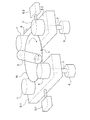
図1は、本説明に係る基板洗浄装置の全体構成を示す模式的斜視図である。図1に示すように、基板洗浄装置1は、半導体ウェハ等の基板Wの周縁部を保持し基板Wをその軸心の周りに回転させる複数のローラ1と、ローラ1により回転される基板Wの表面に接触する洗浄部材2とを備えている。図示例では、4個のローラ1が設置されており、各ローラ1はスピンドル3に連結されている。4個のローラ1のうち、例えば、2個のローラ1はスピンドル3を介してモータ4に連結されていて回転駆動されるようになっており、基板Wに回転力を与え、他の2個のローラ1は基板Wの回転を支承するベアリングの働きをしている。なお、全てのローラ1をモータに連結して、全てのローラ1が基板Wに回転力を付与するように構成してもよい。
Embodiments of a substrate cleaning apparatus and method according to the present invention will be described below with reference to FIGS.
FIG. 1 is a schematic perspective view showing the overall configuration of the substrate cleaning apparatus according to the present description. As shown in FIG. 1, a
洗浄部材2は、円柱状で基板Wの直径とほぼ同じ長さを有した長尺状のPVAからなるロールスポンジによって構成され、図示されないホルダーにより保持されている。洗浄部材2は基板Wの回転軸心と直交する回転軸心の周りに回転するように構成されている。なお、洗浄部材は、基板Wの直径より小さい直径を有し基板Wの回転軸心と平行な回転軸心の周りに回転するペンシル型洗浄部材であってもよい。また、基板Wの裏面側に、基板Wの裏面を洗浄する洗浄部材を配置し、表板Wの表裏面を同時に洗浄するように構成してもよい。 The cleaning member 2 is constituted by a roll sponge made of a long PVA having a cylindrical shape and substantially the same length as the diameter of the substrate W, and is held by a holder (not shown). The cleaning member 2 is configured to rotate around a rotation axis perpendicular to the rotation axis of the substrate W. The cleaning member may be a pencil type cleaning member that has a diameter smaller than that of the substrate W and rotates around a rotation axis parallel to the rotation axis of the substrate W. Further, a cleaning member for cleaning the back surface of the substrate W may be disposed on the back surface side of the substrate W, and the front and back surfaces of the front plate W may be cleaned at the same time.
図1に示すように、左側の2つのローラ1は第1ステージ5−1により支持されており、右側の2つのローラ1は第2ステージ5−2により支持されている。第1ステージ5−1には、第1エアシリンダ6−1が連結されており、第2ステージ5−2には、第2エアシリンダ6−2が連結されている。また、第2ステージ5−2には加速度センサからなる振動センサ8が取り付けられている。
As shown in FIG. 1, the two
図1に示すように構成された基板洗浄装置は、以下のように動作する。
第1ステージ5−1と第2ステージ5−2とがそれぞれ第1エアシリンダ6−1と第2エアシリンダ6−2によって離間する方向に移動した状態で、基板Wが供給されると、第1エアシリンダ6−1と第2エアシリンダ6−2が作動して第1ステージ5−1と第2ステージ5−2とが前進し、基板Wの周縁部は4つのローラ1により保持される。すなわち、図1に示すように、基板Wは4つのローラ1により水平に保持された状態になる。この状態でモータ4を駆動してローラ1を回転駆動し、基板Wに回転力を付与し、モータ4に連結されていないローラ1によって基板Wの回転を支承する。
The substrate cleaning apparatus configured as shown in FIG. 1 operates as follows.
When the substrate W is supplied in a state where the first stage 5-1 and the second stage 5-2 are moved away from each other by the first air cylinder 6-1 and the second air cylinder 6-2, respectively. The first air cylinder 6-1 and the second air cylinder 6-2 are operated to advance the first stage 5-1 and the second stage 5-2, and the peripheral edge of the substrate W is held by the four
このように基板Wを回転させた状態で、図示されない洗浄液供給ノズルから基板Wの表面(上面)に洗浄液を供給しつつ、洗浄部材2を回転させながら下降させて回転中の基板Wの表面に所定の荷重で洗浄部材2を接触させる。これによって、洗浄液の存在下で基板Wの表面を洗浄部材2によりスクラブ洗浄する。
基板Wが回転している間、基板Wの周縁部にはノッチ(V字型の切れ込み)nが形成されているため、ノッチnがローラ1に当たると、ローラ1が振動する。ローラ1の振動に伴い、ローラ1を支持している第1ステージ5−1と第2ステージ5−2とが振動する。この振動は、第2ステージ5−2に設置された加速度センサからなる振動センサ8によって検出することができる。
While the substrate W is rotated as described above, the cleaning liquid is supplied to the surface (upper surface) of the substrate W from a cleaning liquid supply nozzle (not shown), and the cleaning member 2 is lowered while rotating to the surface of the rotating substrate W. The cleaning member 2 is brought into contact with a predetermined load. Thus, the surface of the substrate W is scrubbed by the cleaning member 2 in the presence of the cleaning liquid.
While the substrate W is rotating, a notch (V-shaped notch) n is formed at the peripheral edge of the substrate W. Therefore, when the notch n hits the
次に、振動センサ8によって検出した振動から基板Wとローラ1との間に発生したスリップを検知し、スリップが検知されたときに基板Wに対するローラ1の押し付け力(クランプ力)を増加させる構成について説明する。なお、基板とローラとの間に発生するスリップについて、基板のスリップと短縮して表記する場合もある。
図2は、基板Wのスリップを検知してローラ1の押し付け力を制御する構成を備えた基板洗浄装置を示す模式図である。図2に示すように、第2ステージ5−2に設置された振動センサ8はコントローラ(制御部)10に接続されている。第2ステージ5−2を前後進させる第2エアシリンダ6−2は電空レギュレータ11に接続されており、電空レギュレータ11はコントローラ(制御部)10に接続されている。図2においてローラ1、第1ステージ5−1、第2ステージ5−2、第1エアシリンダ6−1および第2エアシリンダ6−2の構成は、図1に示すとおりである。
Next, a configuration in which a slip generated between the substrate W and the
FIG. 2 is a schematic diagram showing a substrate cleaning apparatus having a configuration for detecting the slip of the substrate W and controlling the pressing force of the
図3は、図2に示すように構成された基板洗浄装置によるクランプ力の補正方法を示すグラフである。基板Wの洗浄中に、振動センサ8によって検出された振動は、内部にアンプや演算部等を備えたコントローラ(制御部)10によって増幅された後に実効値変換される。その結果、コントローラ10は図3の上段に示すようなRMS波形を得る。発明者らは、上記のシステムによって得られるRMS波形をモニタリングすると、基板のスリップが生じたときにRMS波形の値が小さくなることを確認した。そこで、コントローラ10は、RMS波形を監視し、図3の上段に示すように、RMS波形が所定の閾値を下回ったら、基板Wの回転速度が設定回転速度より低下して基板Wのスリップが発生したと判定し、電空レギュレータ11に圧力制御信号を送信する。電空レギュレータ11は、コントローラ10から送信された圧力制御信号に基づいて、図3の下段に示すように、上昇させたクランプエアー圧を第2エアシリンダ6−2に供給し、基板Wに対するローラ1の押し付け力(クランプ力)を増加させる。第2エアシリンダ6−2は、ローラ1を所定の押し付け力で基板Wに押し付けるローラ押し付け機構を構成している。ローラ押し付け機構は、エアシリンダに代えて電動シリンダであってもよい。コントローラ10は、クランプ力を増加させた後に、図3の上段に示すように、RMS波形が閾値を上回ったら、基板Wの回転速度が設定回転速度に回復したと判定し、電空レギュレータ11に圧力制御信号を送信する。電空レギュレータ11は、コントローラ10から送信された圧力制御信号に基づいて、図3の下段に示すように、元の圧力に低下させたクランプエアー圧を第2エアシリンダ6−2に供給し、基板Wに対するローラ1の押し付け力(クランプ力)を標準設定値に戻す。
FIG. 3 is a graph showing a method of correcting the clamping force by the substrate cleaning apparatus configured as shown in FIG. During the cleaning of the substrate W, the vibration detected by the
このように、本発明によれば、基板Wのスリップが検知されたときに、ローラ1のクランプ力を増加させて基板Wをスリップ状態から設定された回転速度に閉ループ制御(CLC制御)によって回復させることができる。基板Wの洗浄中、RMS波形を常時監視し、クランプ力の補正を常に行うことにより、散発的に生ずる基板のスリップを直ちに解消することができる。
As described above, according to the present invention, when the slip of the substrate W is detected, the clamping force of the
図4は、基板Wのスリップを検知する検知手段の他の態様を示す模式的斜視図である。図4においては、洗浄部材2、第1ステージ5−1,第2ステージ5−2、第1エアシリンダ6−1,第2エアシリンダ6−2等は図示を省略している。
図4に示す実施形態では、基板Wの周縁部に形成されたノッチnを検出する光センサ20が設置されている。光センサ20は、光を投光する投光部21と、投光部21からの光を受光する受光部22とから構成されている。投受光部21,22は保持部23により保持されている。また、投受光部21,22はコントローラ(制御部)10に接続されている。
FIG. 4 is a schematic perspective view showing another aspect of the detecting means for detecting the slip of the substrate W. FIG. In FIG. 4, the cleaning member 2, the first stage 5-1, the second stage 5-2, the first air cylinder 6-1, the second air cylinder 6-2, and the like are not shown.
In the embodiment shown in FIG. 4, an
光センサ20は、回転している基板Wのノッチnを検出可能な位置に光軸を合わせてあり、投光部21からの光は通常遮光状態であり、基板Wのノッチnが光軸を通過する時にのみ受光部22は投光部21からの光を受光し、光を電気的信号に変換し、コントローラ10に出力する。コントローラ10は、光センサ20からの信号に基づいて基板Wの回転速度が設定回転速度より低下したことを検知して基板Wのスリップが発生したと判定し、電空レギュレータ11(図2参照)に圧力制御信号を送信する。電空レギュレータ11は、コントローラ10から送信された圧力制御信号に基づいて上昇させたクランプエアー圧を第2エアシリンダ6−2(図2参照)に供給し、基板Wに対するローラ1の押し付け力(クランプ力)を増加させる。その後、光センサ20により基板Wの回転速度の監視を引き続き行い、基板Wの回転速度が設定回転速度に回復したら、基板Wへのローラ1の押し付け力(クランプ力)を標準設定値に戻す。
The
図5は、基板Wのスリップを検知する検知手段の更に他の態様を示す模式的斜視図である。図5においては、洗浄部材2、第1ステージ5−1,第2ステージ5−2、第1エアシリンダ6−1,第2エアシリンダ6−2等は図示を省略している。
図5に示す実施形態では、基板Wの周縁部に接触して回転する従動ローラ30が設置されている。従動ローラ30には、従動ローラ30と一体に回転するスピンドル31が固定されており、スピンドル31の下端部を囲むように回転速度センサ32が設置されている。図5に示す実施形態では、従動ローラ30を基板Wの周縁部に接触させ、基板Wの回転を利用して従動ローラ30を回転させ、従動ローラ30の回転速度を回転速度センサ32で測定するようにしている。回転速度センサ32はコントローラ(制御部)10に接続されている。コントローラ10は、回転速度センサ32からの信号に基づいて基板Wの回転速度が設定回転速度より低下したことを検知して基板Wのスリップが発生したと判定し、電空レギュレータ11(図2参照)に圧力制御信号を送信する。電空レギュレータ11は、コントローラ10から送信された圧力制御信号に基づいて上昇させたクランプエアー圧を第2エアシリンダ6−2(図2参照)に供給し、基板Wに対するローラ1の押し付け力(クランプ力)を増加させる。その後、回転速度センサ32により基板Wの回転速度の監視を引き続き行い、基板Wの回転速度が設定回転速度に回復したら、基板Wへのローラ1の押し付け力(クランプ力)を標準設定値に戻す。
FIG. 5 is a schematic perspective view showing still another aspect of the detecting means for detecting the slip of the substrate W. FIG. In FIG. 5, the cleaning member 2, the first stage 5-1, the second stage 5-2, the first air cylinder 6-1, the second air cylinder 6-2, and the like are not shown.
In the embodiment shown in FIG. 5, a driven
次に、図1乃至図5に示すような構成を備えた基板洗浄装置を用いて、装置のセッティング時あるいは基板の洗浄処理の開始前などに、ローラ1の押し付け力(クランプ力)を調整する方法について説明する。
図1において、洗浄部材2が基板Wに接触していない状態においてローラ1の押し付け力(クランプ力)を次第に強めて基板Wの回転が始まるクランプ力を求め、この基板Wの回転が始まるクランプ力を基にして基板を設定回転速度で回転させるためのクランプ力を最適化することができる。この場合、基板Wの回転開始は、振動センサ8、光センサ20、回転速度センサ32により検知可能であり、クランプ力はコントローラ(制御部)10により演算することができる。
Next, the pressing force (clamping force) of the
In FIG. 1, in a state where the cleaning member 2 is not in contact with the substrate W, the pressing force (clamping force) of the
また、洗浄部材2を基板Wに接触させ、基板Wを設定回転速度で回転させた状態においてローラの押し付け力(クランプ力)を徐々に弱くしていき、基板Wがスリップし始めるときのクランプ力を求める。そして、この基板Wがスリップし始めるときのクランプ力を基にして、クランプ力を段階的に少しずつ増加させていき、基板Wがスリップしなくなるときの最小のクランプ力を求めることができる。この場合、基板Wのスリップは、上述したように、振動センサ8、光センサ20、回転速度センサ32により検知可能であり、最小のクランプ力はコントローラ(制御部)10により演算することができる。
Further, when the cleaning member 2 is brought into contact with the substrate W and the substrate W is rotated at the set rotational speed, the pressing force (clamping force) of the roller is gradually weakened, and the clamping force when the substrate W starts to slip. Ask for. Then, based on the clamping force when the substrate W starts to slip, the clamping force is gradually increased step by step, and the minimum clamping force when the substrate W does not slip can be obtained. In this case, as described above, the slip of the substrate W can be detected by the
図1乃至図5に示す実施形態においては、基板Wを水平の状態で回転させる構成としたが、基板Wを垂直の状態で回転させるようにしてもよい。
これまで本発明の実施形態について説明したが、本発明は上述の実施形態に限定されず、その技術思想の範囲内において、種々の異なる形態で実施されてよいことは勿論である。
In the embodiment shown in FIGS. 1 to 5, the substrate W is rotated in a horizontal state. However, the substrate W may be rotated in a vertical state.
Although the embodiment of the present invention has been described so far, the present invention is not limited to the above-described embodiment, and it is needless to say that the present invention may be implemented in various different forms within the scope of the technical idea.
1 ローラ
2 洗浄部材
3 スピンドル
4 モータ
5−1 第1ステージ
5−2 第2ステージ
6−1 第1エアシリンダ
6−2 第2エアシリンダ
8 振動センサ
10 コントローラ(制御部)
11 電空レギュレータ
20 光センサ
21 投光部
22 受光部
23 保持部
30 従動ローラ
31 スピンドル
32 回転速度センサ
n ノッチ
W 基板
DESCRIPTION OF
DESCRIPTION OF
Claims (10)
基板の回転速度が設定された回転速度より低下する状態になる基板とローラとの間に発生するスリップを検知するスリップ検知手段と、
前記ローラを所定の押し付け力で基板に押し付けるローラ押し付け機構と、
前記スリップ検知手段が基板とローラとの間のスリップを検知した際に、前記ローラ押し付け機構による押し付け力を増加させる制御部とを備えたことを特徴とする基板洗浄装置。 In a substrate cleaning apparatus for cleaning a substrate by supplying a cleaning liquid to the substrate while rotating the substrate by rotating the roller while holding the peripheral portion of the substrate with a plurality of rollers and bringing a cleaning member into contact with the rotating substrate ,
Slip detecting means for detecting a slip generated between the substrate and the roller that is in a state where the rotational speed of the substrate is lower than the set rotational speed;
A roller pressing mechanism that presses the roller against the substrate with a predetermined pressing force;
A substrate cleaning apparatus, comprising: a controller that increases a pressing force by the roller pressing mechanism when the slip detection means detects a slip between the substrate and the roller.
複数の回転するローラを所定の押し付け力で基板に押し付けて基板を設定された回転速度で回転させ、回転する基板に洗浄部材を接触させて洗浄し、
前記洗浄中に、基板の回転速度が前記設定された回転速度より低下する状態になる基板とローラとの間に発生するスリップの有無を監視し、
前記スリップが発生した際に、基板に対する前記ローラの押し付け力を増加させて基板の洗浄を継続することを特徴とする基板洗浄方法。 In the substrate cleaning method of cleaning the substrate by supplying the cleaning liquid to the substrate while rotating the substrate by rotating the roller while holding the peripheral edge of the substrate with a plurality of rollers and bringing the cleaning member into contact with the rotating substrate,
A plurality of rotating rollers are pressed against the substrate with a predetermined pressing force, the substrate is rotated at a set rotation speed, and the cleaning member is brought into contact with the rotating substrate for cleaning.
During the cleaning, the presence or absence of slip generated between the substrate and the roller, where the rotation speed of the substrate becomes lower than the set rotation speed, is monitored,
When the slip occurs, the substrate cleaning method is characterized in that the pressing force of the roller against the substrate is increased to continue the cleaning of the substrate.
Priority Applications (1)
| Application Number | Priority Date | Filing Date | Title |
|---|---|---|---|
| JP2015030489A JP6491903B2 (en) | 2015-02-19 | 2015-02-19 | Substrate cleaning apparatus and method |
Applications Claiming Priority (1)
| Application Number | Priority Date | Filing Date | Title |
|---|---|---|---|
| JP2015030489A JP6491903B2 (en) | 2015-02-19 | 2015-02-19 | Substrate cleaning apparatus and method |
Publications (3)
| Publication Number | Publication Date |
|---|---|
| JP2016152382A JP2016152382A (en) | 2016-08-22 |
| JP2016152382A5 JP2016152382A5 (en) | 2018-02-08 |
| JP6491903B2 true JP6491903B2 (en) | 2019-03-27 |
Family
ID=56696758
Family Applications (1)
| Application Number | Title | Priority Date | Filing Date |
|---|---|---|---|
| JP2015030489A Active JP6491903B2 (en) | 2015-02-19 | 2015-02-19 | Substrate cleaning apparatus and method |
Country Status (1)
| Country | Link |
|---|---|
| JP (1) | JP6491903B2 (en) |
Cited By (1)
| Publication number | Priority date | Publication date | Assignee | Title |
|---|---|---|---|---|
| WO2023119847A1 (en) * | 2021-12-24 | 2023-06-29 | 株式会社荏原製作所 | Substrate processing method and substrate processing device |
Families Citing this family (4)
| Publication number | Priority date | Publication date | Assignee | Title |
|---|---|---|---|---|
| JP6792512B2 (en) | 2017-05-16 | 2020-11-25 | 株式会社荏原製作所 | Substrate cleaning equipment and substrate processing equipment |
| JP7115403B2 (en) * | 2019-04-11 | 2022-08-09 | 株式会社Sumco | Wafer rotation detection method and wafer rotation detection system |
| JP7078602B2 (en) | 2019-12-25 | 2022-05-31 | 株式会社荏原製作所 | Devices and methods for calculating the rotation speed of a substrate in a cleaning device, a polishing device, and a cleaning device. |
| CN114472265B (en) * | 2021-12-31 | 2022-11-08 | 华海清科股份有限公司 | Wafer cleaning method and wafer cleaning device |
Family Cites Families (7)
| Publication number | Priority date | Publication date | Assignee | Title |
|---|---|---|---|---|
| JPH10289889A (en) * | 1997-04-16 | 1998-10-27 | Dainippon Screen Mfg Co Ltd | Substrate treatment apparatus |
| JPH11219930A (en) * | 1998-01-30 | 1999-08-10 | Ebara Corp | Cleaning device |
| JP4620911B2 (en) * | 2001-09-05 | 2011-01-26 | 芝浦メカトロニクス株式会社 | Substrate processing apparatus and processing method |
| JP2003092278A (en) * | 2001-09-18 | 2003-03-28 | Shibaura Mechatronics Corp | Apparatus and method for treatment of substrate |
| US7685667B2 (en) * | 2005-06-14 | 2010-03-30 | Taiwan Semiconductor Manufacturing Co., Ltd. | Post-CMP cleaning system |
| US20080216863A1 (en) * | 2007-03-09 | 2008-09-11 | Applied Materials, Inc. | Methods and apparatus for monitoring the rotation of a substrate during cleaning |
| JP6125884B2 (en) * | 2013-04-23 | 2017-05-10 | 株式会社荏原製作所 | Substrate processing apparatus and manufacturing method of processing substrate |
-
2015
- 2015-02-19 JP JP2015030489A patent/JP6491903B2/en active Active
Cited By (1)
| Publication number | Priority date | Publication date | Assignee | Title |
|---|---|---|---|---|
| WO2023119847A1 (en) * | 2021-12-24 | 2023-06-29 | 株式会社荏原製作所 | Substrate processing method and substrate processing device |
Also Published As
| Publication number | Publication date |
|---|---|
| JP2016152382A (en) | 2016-08-22 |
Similar Documents
| Publication | Publication Date | Title |
|---|---|---|
| JP6491903B2 (en) | Substrate cleaning apparatus and method | |
| KR102401524B1 (en) | Substrate cleaning apparatus and method executed thereby | |
| JP6145334B2 (en) | Substrate processing equipment | |
| US8051522B2 (en) | Substrate treatment apparatus | |
| JP6767834B2 (en) | Substrate cleaning equipment and substrate processing equipment | |
| US20170239784A1 (en) | Polishing apparatus and polishing method | |
| JP2016152382A5 (en) | ||
| JP2013153141A5 (en) | ||
| JP2009107084A (en) | Grinding device | |
| JP2006324429A (en) | Method for cleaning after mechanical chemical polishing | |
| JP3615724B2 (en) | Wafer cleaning device | |
| JP4719052B2 (en) | Substrate processing apparatus and substrate processing method | |
| JP6435036B2 (en) | Rotation holding device and substrate cleaning device | |
| JP2007294490A (en) | Cleaning equipment of substrate, and cleaning method of substrate employing it | |
| JP2010238765A (en) | Double-side grinding device of semiconductor wafer and double-side grinding method | |
| JP6895565B2 (en) | Substrate Cleaning Equipment and Methods Performed on Substrate Cleaning Equipment | |
| JP2002313765A (en) | Brush cleaning device and control method therefor | |
| JPH10189512A (en) | Substrate cleaning device | |
| JP6632900B2 (en) | Substrate cleaning apparatus, cleaning tool and substrate processing apparatus, and method of removing, attaching and replacing cleaning tool | |
| JP4493286B2 (en) | Work polishing method and apparatus | |
| JP6736713B2 (en) | Substrate cleaning apparatus and method performed in substrate cleaning apparatus | |
| JP2006237098A (en) | Double-sided polishing apparatus and method of double-sided polishing | |
| JP2005317576A (en) | Substrate cleaning apparatus, and method for deciding standard position of cleaning brush in substrate cleaning apparatus | |
| JP6243229B2 (en) | Rotation holding device and substrate cleaning device | |
| JP2005268330A (en) | Polishing method of semiconductor wafer |
Legal Events
| Date | Code | Title | Description |
|---|---|---|---|
| A521 | Request for written amendment filed |
Free format text: JAPANESE INTERMEDIATE CODE: A523 Effective date: 20171220 |
|
| A621 | Written request for application examination |
Free format text: JAPANESE INTERMEDIATE CODE: A621 Effective date: 20171220 |
|
| A977 | Report on retrieval |
Free format text: JAPANESE INTERMEDIATE CODE: A971007 Effective date: 20180827 |
|
| A131 | Notification of reasons for refusal |
Free format text: JAPANESE INTERMEDIATE CODE: A131 Effective date: 20180904 |
|
| A521 | Request for written amendment filed |
Free format text: JAPANESE INTERMEDIATE CODE: A523 Effective date: 20181003 |
|
| TRDD | Decision of grant or rejection written | ||
| A01 | Written decision to grant a patent or to grant a registration (utility model) |
Free format text: JAPANESE INTERMEDIATE CODE: A01 Effective date: 20190219 |
|
| A61 | First payment of annual fees (during grant procedure) |
Free format text: JAPANESE INTERMEDIATE CODE: A61 Effective date: 20190304 |
|
| R150 | Certificate of patent or registration of utility model |
Ref document number: 6491903 Country of ref document: JP Free format text: JAPANESE INTERMEDIATE CODE: R150 |
|
| R250 | Receipt of annual fees |
Free format text: JAPANESE INTERMEDIATE CODE: R250 |
|
| R250 | Receipt of annual fees |
Free format text: JAPANESE INTERMEDIATE CODE: R250 |
|
| R250 | Receipt of annual fees |
Free format text: JAPANESE INTERMEDIATE CODE: R250 |