JP6759689B2 - 歪みセンサユニット - Google Patents
歪みセンサユニット Download PDFInfo
- Publication number
- JP6759689B2 JP6759689B2 JP2016094481A JP2016094481A JP6759689B2 JP 6759689 B2 JP6759689 B2 JP 6759689B2 JP 2016094481 A JP2016094481 A JP 2016094481A JP 2016094481 A JP2016094481 A JP 2016094481A JP 6759689 B2 JP6759689 B2 JP 6759689B2
- Authority
- JP
- Japan
- Prior art keywords
- strain sensor
- base material
- strain
- sensor unit
- longitudinal direction
- Prior art date
- Legal status (The legal status is an assumption and is not a legal conclusion. Google has not performed a legal analysis and makes no representation as to the accuracy of the status listed.)
- Active
Links
Images


Classifications
-
- G—PHYSICS
- G01—MEASURING; TESTING
- G01B—MEASURING LENGTH, THICKNESS OR SIMILAR LINEAR DIMENSIONS; MEASURING ANGLES; MEASURING AREAS; MEASURING IRREGULARITIES OF SURFACES OR CONTOURS
- G01B7/00—Measuring arrangements characterised by the use of electric or magnetic techniques
- G01B7/16—Measuring arrangements characterised by the use of electric or magnetic techniques for measuring the deformation in a solid, e.g. by resistance strain gauge
- G01B7/18—Measuring arrangements characterised by the use of electric or magnetic techniques for measuring the deformation in a solid, e.g. by resistance strain gauge using change in resistance
-
- G—PHYSICS
- G01—MEASURING; TESTING
- G01L—MEASURING FORCE, STRESS, TORQUE, WORK, MECHANICAL POWER, MECHANICAL EFFICIENCY, OR FLUID PRESSURE
- G01L1/00—Measuring force or stress, in general
- G01L1/20—Measuring force or stress, in general by measuring variations in ohmic resistance of solid materials or of electrically-conductive fluids; by making use of electrokinetic cells, i.e. liquid-containing cells wherein an electrical potential is produced or varied upon the application of stress
- G01L1/22—Measuring force or stress, in general by measuring variations in ohmic resistance of solid materials or of electrically-conductive fluids; by making use of electrokinetic cells, i.e. liquid-containing cells wherein an electrical potential is produced or varied upon the application of stress using resistance strain gauges
- G01L1/2206—Special supports with preselected places to mount the resistance strain gauges; Mounting of supports
-
- G—PHYSICS
- G01—MEASURING; TESTING
- G01L—MEASURING FORCE, STRESS, TORQUE, WORK, MECHANICAL POWER, MECHANICAL EFFICIENCY, OR FLUID PRESSURE
- G01L1/00—Measuring force or stress, in general
- G01L1/20—Measuring force or stress, in general by measuring variations in ohmic resistance of solid materials or of electrically-conductive fluids; by making use of electrokinetic cells, i.e. liquid-containing cells wherein an electrical potential is produced or varied upon the application of stress
- G01L1/22—Measuring force or stress, in general by measuring variations in ohmic resistance of solid materials or of electrically-conductive fluids; by making use of electrokinetic cells, i.e. liquid-containing cells wherein an electrical potential is produced or varied upon the application of stress using resistance strain gauges
- G01L1/2268—Arrangements for correcting or for compensating unwanted effects
Description
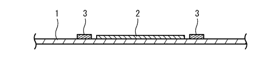
図1及び図2に示す本発明の第一実施形態に係る歪みセンサユニットは、伸縮性を有する基材1と、この基材1に積層され、基材1の伸縮方向に沿って配設される帯状の歪みセンサ2と、この歪みセンサ2の長手方向両端近傍に歪みセンサ2の長手方向に交差する方向に延びるよう配設され、歪みセンサ2よりも曲げ弾性率が大きい1対の変形抑制部3とを備える。
基材1は、当該歪みセンサユニットの構造材であり、シート状の材料から形成され、少なくとも歪みセンサ2を保持する部分が帯状に形成される。この基材1は、歪みセンサ2を保持すると共に、測定対象に取り付け可能に構成される。この基材1は、測定対象と共に伸縮し、この伸縮を歪みセンサ2に伝達することによって歪みセンサ2を測定対象と共に伸縮させる機能を果たす。
前記歪センサ2は、基材1の表面(測定対象と反対側の面)に重ねられて固定されている。より詳しくは、当該歪みセンサユニットにおいて、歪センサ2は、基材1の短手方向中央に貼設されている。このように、歪センサ2を基材1の中央部に貼設することによって、歪センサ2の周囲の基材1が均等に伸縮し、歪センサ2の位置ずれを抑制できる。
1対の変形抑制部3は、歪みセンサ2の長手方向両端部の基材1の変形を抑制することにより、1対の変形抑制部3の間の基材1の反り返りを防止して測定対象への密着性を向上することで、歪みセンサ2の位置ずれを抑制する。
当該歪みセンサユニットは、歪みセンサ2の長手方向両端近傍に曲げ弾性率が大きい1対の変形抑制部3を備えることによって、歪みセンサ2の両側の基材1が変形しにくいので、歪みセンサ2の位置ずれが抑制されることで比較的検出精度が高い。
図3及び図4に示す本発明の第二実施形態に係る歪みセンサユニットは、伸縮性を有する基材1と、この基材1に積層され、基材1の伸縮方向に沿って配設される帯状の歪みセンサ2と、この歪みセンサ2の長手方向両端近傍に歪みセンサ2の長手方向に交差する方向に延びるよう配設され、歪みセンサ2よりも曲げ弾性率が大きい1対の変形抑制部3aと、基材1の裏面の平面視で歪みセンサ2の長手方向両側に配設される1対の滑り止め4を備える。
図3及び図4の歪みセンサユニットにおける変形抑制部3aは、歪みセンサ2の端部に重畳されるよう配設される点を除いて、図1及び図2の歪みセンサユニットにおける変形抑制部3と同様である。
滑り止め4は、基材1の裏面に積層され、測定対象との摩擦を増大して、基材1ひいて場歪みセンサ2が位置ずれすることをより確実に抑制する。
図5に示す本発明の第三実施形態に係る歪みセンサユニットは、伸縮性を有する基材1bと、この基材1bに積層され、基材1bの伸縮方向に沿って平行に配設される複数(2つ)の歪みセンサ2と、この複数歪みセンサ2の長手方向両端近傍に歪みセンサ2の長手方向に交差する方向に延びるよう配設され、歪みセンサ2よりも曲げ弾性率が大きい1対の変形抑制部3とを備える。
基材1bは、複数の歪みセンサ2の間に、これらの歪みセンサ2と平行なスリット5を有する。
スリット5は、複数の歪みセンサ2間で基材1bを分断することにより、複数の歪みセンサ2が互いに独立して伸縮できるようにする。つまり、当該歪みセンサユニットは、1つの歪みセンサ2の変位が他の歪みセンサ2の変位に影響を及ぼしにくいので、比較的検出精度が高い。
前記実施形態は、本発明の構成を限定するものではない。従って、前記実施形態は、本明細書の記載及び技術常識に基づいて前記実施形態各部の構成要素の省略、置換又は追加が可能であり、それらは全て本発明の範囲に属するものと解釈されるべきである。
2 歪みセンサ
3,3a,3c,3d,3e,3f 変形抑制部
4 滑り止め
5 スリット
Claims (5)
- 伸縮性を有する基材と、
前記基材に積層され、前記基材の伸縮方向に沿って配設される帯状の1又は複数の歪みセンサ素子と、
前記1又は複数の歪みセンサ素子の長手方向両端部近傍に歪みセンサ素子の幅方向に延びるよう前記基材に配設され、前記歪みセンサ素子よりも曲げ弾性率が大きく、上記基材の変形を抑制する1対の変形抑制部と
を備え、
前記1対の変形抑制部が前記1又は複数の歪みセンサ素子から離間して配設され、
前記変形抑制部の前記歪みセンサ素子の幅方向の長さが前記歪みセンサ素子の平均幅以上である歪みセンサユニット。 - 前記1対の変形抑制部と前記1又は複数の歪みセンサ素子の長手方向先端との距離が、前記1又は複数の歪みセンサ素子の平均長さの1/5以下である請求項1に記載の歪みセンサユニット。
- 複数の前記歪みセンサ素子が平行に配設され、
前記基材が前記複数の歪みセンサ素子の間に歪みセンサ素子と平行なスリットを有する請求項1又は請求項2に記載の歪みセンサユニット。 - 前記変形抑制部が歪みセンサ素子の長手方向に交差する方向の中心軸を有する密巻きコイルバネを含む請求項1、請求項2又は請求項3に記載の歪みセンサユニット。
- 前記基材の裏面の平面視で歪みセンサ素子の長手方向両側に配設される1対の滑り止めをさらに備える請求項1から請求項4のいずれか1項に記載の歪みセンサユニット。
Priority Applications (4)
| Application Number | Priority Date | Filing Date | Title |
|---|---|---|---|
| JP2016094481A JP6759689B2 (ja) | 2016-05-10 | 2016-05-10 | 歪みセンサユニット |
| CN201780028543.6A CN109073353B (zh) | 2016-05-10 | 2017-04-28 | 应变传感器单元 |
| PCT/JP2017/017068 WO2017195683A1 (ja) | 2016-05-10 | 2017-04-28 | 歪みセンサユニット |
| US16/185,147 US11175124B2 (en) | 2016-05-10 | 2018-11-09 | Strain sensor unit |
Applications Claiming Priority (1)
| Application Number | Priority Date | Filing Date | Title |
|---|---|---|---|
| JP2016094481A JP6759689B2 (ja) | 2016-05-10 | 2016-05-10 | 歪みセンサユニット |
Publications (3)
| Publication Number | Publication Date |
|---|---|
| JP2017203656A JP2017203656A (ja) | 2017-11-16 |
| JP2017203656A5 JP2017203656A5 (ja) | 2019-06-06 |
| JP6759689B2 true JP6759689B2 (ja) | 2020-09-23 |
Family
ID=60266568
Family Applications (1)
| Application Number | Title | Priority Date | Filing Date |
|---|---|---|---|
| JP2016094481A Active JP6759689B2 (ja) | 2016-05-10 | 2016-05-10 | 歪みセンサユニット |
Country Status (4)
| Country | Link |
|---|---|
| US (1) | US11175124B2 (ja) |
| JP (1) | JP6759689B2 (ja) |
| CN (1) | CN109073353B (ja) |
| WO (1) | WO2017195683A1 (ja) |
Families Citing this family (8)
| Publication number | Priority date | Publication date | Assignee | Title |
|---|---|---|---|---|
| CN113016237A (zh) * | 2018-11-16 | 2021-06-22 | 大日本印刷株式会社 | 配线基板和配线基板的制造方法 |
| JP6696634B1 (ja) * | 2018-11-16 | 2020-05-20 | 大日本印刷株式会社 | 配線基板及び配線基板の製造方法 |
| WO2020166122A1 (ja) * | 2019-02-12 | 2020-08-20 | 株式会社村田製作所 | ひずみセンサ |
| TWI723587B (zh) * | 2019-10-17 | 2021-04-01 | 國立中央大學 | 動態應變式索力監測計與其監測方法 |
| JP2022021252A (ja) * | 2020-07-21 | 2022-02-02 | ヤマハ株式会社 | 生体センサ |
| CN112161738B (zh) * | 2020-09-17 | 2022-04-08 | 五邑大学 | 气压传感器及制作方法 |
| CN112525061B (zh) * | 2020-11-09 | 2022-09-13 | 西南科技大学 | 一种采用纳米复合材料的无线应变测试装置及方法 |
| EP4314744A1 (en) * | 2021-03-26 | 2024-02-07 | Julius Zorn, Inc. | Device and method for monitoring compression level of a compression garment |
Family Cites Families (17)
| Publication number | Priority date | Publication date | Assignee | Title |
|---|---|---|---|---|
| JP2000159052A (ja) * | 1998-11-20 | 2000-06-13 | Fujikura Ltd | フィルムアンテナ、それを使用した着座センサ及びそれを使用したエアバック制御装置 |
| JP4013149B2 (ja) * | 2004-03-10 | 2007-11-28 | 清水建設株式会社 | 構造物の健全性判定装置 |
| US7791476B2 (en) * | 2006-02-21 | 2010-09-07 | Elesys North America, Inc. | Occupant sensor and method for seat belt or other monitoring |
| FR2904590A1 (fr) * | 2006-08-02 | 2008-02-08 | Aisin Seiki | Capteur de detection de cassage de vitre |
| JP5397896B2 (ja) | 2009-08-25 | 2014-01-22 | 独立行政法人産業技術総合研究所 | カーボンナノチューブを用いた伸縮装置、伸縮駆動装置およびcnt膜構造体 |
| JP5924725B2 (ja) * | 2011-11-14 | 2016-05-25 | ヤマハ株式会社 | 歪みセンサ及び歪みセンサの製造方法 |
| US10265019B2 (en) * | 2013-03-29 | 2019-04-23 | Oxystrap Int'l, Inc. | Electronic headwear |
| JP5764609B2 (ja) * | 2013-05-08 | 2015-08-19 | 富士重工業株式会社 | ブッシュ分力検出装置 |
| EP2801549B1 (en) * | 2013-05-10 | 2018-01-31 | Yamaha Corporation | Strain sensor based on carbon nanotubes and method for its manufacture |
| JP5839150B2 (ja) * | 2013-05-24 | 2016-01-06 | 日立金属株式会社 | 圧力センサ及びそれを用いたマスフローメータ並びにマスフローコントローラ |
| US10209055B2 (en) * | 2014-03-03 | 2019-02-19 | Bando Chemical Industries, Ltd. | Sensor device and stretchable structure |
| WO2016060031A1 (ja) * | 2014-10-17 | 2016-04-21 | ヤマハ株式会社 | データグローブ |
| EP3208687B1 (en) | 2014-10-17 | 2019-11-27 | Yamaha Corporation | Data glove |
| JP6488140B2 (ja) * | 2015-02-06 | 2019-03-20 | 日本メクトロン株式会社 | 導電性伸縮基板および歪センサ |
| JP6325482B2 (ja) * | 2015-04-06 | 2018-05-16 | バンドー化学株式会社 | 静電容量型センサシート及びセンサ装置 |
| JP6506653B2 (ja) * | 2015-07-30 | 2019-04-24 | 日本メクトロン株式会社 | 伸縮性配線基板 |
| CN105486218B (zh) * | 2016-01-12 | 2019-07-02 | 山东大学 | 一种监测沥青路面应变的机敏材料应变计与应用 |
-
2016
- 2016-05-10 JP JP2016094481A patent/JP6759689B2/ja active Active
-
2017
- 2017-04-28 WO PCT/JP2017/017068 patent/WO2017195683A1/ja active Application Filing
- 2017-04-28 CN CN201780028543.6A patent/CN109073353B/zh active Active
-
2018
- 2018-11-09 US US16/185,147 patent/US11175124B2/en active Active
Also Published As
| Publication number | Publication date |
|---|---|
| CN109073353A (zh) | 2018-12-21 |
| US20190094004A1 (en) | 2019-03-28 |
| CN109073353B (zh) | 2022-03-18 |
| US11175124B2 (en) | 2021-11-16 |
| JP2017203656A (ja) | 2017-11-16 |
| WO2017195683A1 (ja) | 2017-11-16 |
Similar Documents
| Publication | Publication Date | Title |
|---|---|---|
| JP6759689B2 (ja) | 歪みセンサユニット | |
| JP6264825B2 (ja) | 歪みセンサ付き布帛及び被服 | |
| JP6014906B2 (ja) | 歪みセンサ | |
| JP6019890B2 (ja) | 歪みセンサ付き布帛及び被服 | |
| JP2017075847A (ja) | 動作検出デバイス | |
| JP6341268B2 (ja) | 歪みセンサ付き手袋 | |
| JP6701748B2 (ja) | 歪みセンサ素子 | |
| JP6524663B2 (ja) | データグローブ | |
| US20110125064A1 (en) | Smart clothing for motion physiological measurement and dynamical stable apparatus thereof | |
| JP6470049B2 (ja) | 糸状歪みセンサ素子及び布帛状歪みセンサ素子 | |
| WO2017104596A1 (ja) | 衣料 | |
| JP6488131B2 (ja) | 足運動検出サポーター | |
| JP2016121975A (ja) | 歪み検出センサ素子及び外力検出アレイモジュール | |
| WO2018047718A1 (ja) | 異方性歪みセンサシート及び衣類 | |
| JP6848458B2 (ja) | センサーユニット | |
| JP2017009559A (ja) | 歪みセンサ素子 | |
| JP6821949B2 (ja) | 歪みセンサユニット | |
| JP6561640B2 (ja) | 歪みセンサ素子 | |
| JP2016080520A (ja) | 歪センサ | |
| US20230148077A1 (en) | Motion detection member | |
| JP2016176874A (ja) | 歪みセンサ素子 | |
| JP2017164296A (ja) | 動作検出装置 | |
| JP6687131B2 (ja) | 触覚センサー | |
| JP2017211214A (ja) | 歪みセンサ及び歪みセンサユニット | |
| WO2022019024A1 (ja) | 生体センサ |
Legal Events
| Date | Code | Title | Description |
|---|---|---|---|
| A621 | Written request for application examination |
Free format text: JAPANESE INTERMEDIATE CODE: A621 Effective date: 20190322 |
|
| A521 | Request for written amendment filed |
Free format text: JAPANESE INTERMEDIATE CODE: A523 Effective date: 20190424 |
|
| A131 | Notification of reasons for refusal |
Free format text: JAPANESE INTERMEDIATE CODE: A131 Effective date: 20191203 |
|
| A521 | Request for written amendment filed |
Free format text: JAPANESE INTERMEDIATE CODE: A523 Effective date: 20200127 |
|
| TRDD | Decision of grant or rejection written | ||
| A01 | Written decision to grant a patent or to grant a registration (utility model) |
Free format text: JAPANESE INTERMEDIATE CODE: A01 Effective date: 20200804 |
|
| A61 | First payment of annual fees (during grant procedure) |
Free format text: JAPANESE INTERMEDIATE CODE: A61 Effective date: 20200817 |
|
| R151 | Written notification of patent or utility model registration |
Ref document number: 6759689 Country of ref document: JP Free format text: JAPANESE INTERMEDIATE CODE: R151 |