JP6678688B2 - 端子圧着装置、及び、端子圧着方法 - Google Patents
端子圧着装置、及び、端子圧着方法 Download PDFInfo
- Publication number
- JP6678688B2 JP6678688B2 JP2018004333A JP2018004333A JP6678688B2 JP 6678688 B2 JP6678688 B2 JP 6678688B2 JP 2018004333 A JP2018004333 A JP 2018004333A JP 2018004333 A JP2018004333 A JP 2018004333A JP 6678688 B2 JP6678688 B2 JP 6678688B2
- Authority
- JP
- Japan
- Prior art keywords
- terminal
- terminals
- pair
- carrier
- crimping
- Prior art date
- Legal status (The legal status is an assumption and is not a legal conclusion. Google has not performed a legal analysis and makes no representation as to the accuracy of the status listed.)
- Active
Links
- 238000002788 crimping Methods 0.000 title claims description 76
- 238000000034 method Methods 0.000 title claims description 14
- 238000005520 cutting process Methods 0.000 claims description 85
- 239000004020 conductor Substances 0.000 description 7
- 238000010586 diagram Methods 0.000 description 6
- 238000012545 processing Methods 0.000 description 5
- 210000000078 claw Anatomy 0.000 description 4
- 238000012546 transfer Methods 0.000 description 4
- 238000009434 installation Methods 0.000 description 3
- 238000003780 insertion Methods 0.000 description 2
- 230000037431 insertion Effects 0.000 description 2
- 238000004519 manufacturing process Methods 0.000 description 2
- 239000000463 material Substances 0.000 description 2
- 238000012986 modification Methods 0.000 description 2
- 230000004048 modification Effects 0.000 description 2
- 238000003825 pressing Methods 0.000 description 2
- 238000007796 conventional method Methods 0.000 description 1
- 238000000926 separation method Methods 0.000 description 1
Images


Classifications
-
- H—ELECTRICITY
- H01—ELECTRIC ELEMENTS
- H01R—ELECTRICALLY-CONDUCTIVE CONNECTIONS; STRUCTURAL ASSOCIATIONS OF A PLURALITY OF MUTUALLY-INSULATED ELECTRICAL CONNECTING ELEMENTS; COUPLING DEVICES; CURRENT COLLECTORS
- H01R43/00—Apparatus or processes specially adapted for manufacturing, assembling, maintaining, or repairing of line connectors or current collectors or for joining electric conductors
- H01R43/04—Apparatus or processes specially adapted for manufacturing, assembling, maintaining, or repairing of line connectors or current collectors or for joining electric conductors for forming connections by deformation, e.g. crimping tool
- H01R43/048—Crimping apparatus or processes
- H01R43/055—Crimping apparatus or processes with contact member feeding mechanism
-
- H—ELECTRICITY
- H01—ELECTRIC ELEMENTS
- H01R—ELECTRICALLY-CONDUCTIVE CONNECTIONS; STRUCTURAL ASSOCIATIONS OF A PLURALITY OF MUTUALLY-INSULATED ELECTRICAL CONNECTING ELEMENTS; COUPLING DEVICES; CURRENT COLLECTORS
- H01R4/00—Electrically-conductive connections between two or more conductive members in direct contact, i.e. touching one another; Means for effecting or maintaining such contact; Electrically-conductive connections having two or more spaced connecting locations for conductors and using contact members penetrating insulation
- H01R4/10—Electrically-conductive connections between two or more conductive members in direct contact, i.e. touching one another; Means for effecting or maintaining such contact; Electrically-conductive connections having two or more spaced connecting locations for conductors and using contact members penetrating insulation effected solely by twisting, wrapping, bending, crimping, or other permanent deformation
- H01R4/18—Electrically-conductive connections between two or more conductive members in direct contact, i.e. touching one another; Means for effecting or maintaining such contact; Electrically-conductive connections having two or more spaced connecting locations for conductors and using contact members penetrating insulation effected solely by twisting, wrapping, bending, crimping, or other permanent deformation by crimping
- H01R4/183—Electrically-conductive connections between two or more conductive members in direct contact, i.e. touching one another; Means for effecting or maintaining such contact; Electrically-conductive connections having two or more spaced connecting locations for conductors and using contact members penetrating insulation effected solely by twisting, wrapping, bending, crimping, or other permanent deformation by crimping for cylindrical elongated bodies, e.g. cables having circular cross-section
- H01R4/184—Electrically-conductive connections between two or more conductive members in direct contact, i.e. touching one another; Means for effecting or maintaining such contact; Electrically-conductive connections having two or more spaced connecting locations for conductors and using contact members penetrating insulation effected solely by twisting, wrapping, bending, crimping, or other permanent deformation by crimping for cylindrical elongated bodies, e.g. cables having circular cross-section comprising a U-shaped wire-receiving portion
-
- Y—GENERAL TAGGING OF NEW TECHNOLOGICAL DEVELOPMENTS; GENERAL TAGGING OF CROSS-SECTIONAL TECHNOLOGIES SPANNING OVER SEVERAL SECTIONS OF THE IPC; TECHNICAL SUBJECTS COVERED BY FORMER USPC CROSS-REFERENCE ART COLLECTIONS [XRACs] AND DIGESTS
- Y10—TECHNICAL SUBJECTS COVERED BY FORMER USPC
- Y10T—TECHNICAL SUBJECTS COVERED BY FORMER US CLASSIFICATION
- Y10T29/00—Metal working
- Y10T29/53—Means to assemble or disassemble
- Y10T29/5313—Means to assemble electrical device
- Y10T29/532—Conductor
- Y10T29/53209—Terminal or connector
- Y10T29/53213—Assembled to wire-type conductor
- Y10T29/53222—Means comprising hand-manipulatable implement
- Y10T29/53226—Fastening by deformation
-
- Y—GENERAL TAGGING OF NEW TECHNOLOGICAL DEVELOPMENTS; GENERAL TAGGING OF CROSS-SECTIONAL TECHNOLOGIES SPANNING OVER SEVERAL SECTIONS OF THE IPC; TECHNICAL SUBJECTS COVERED BY FORMER USPC CROSS-REFERENCE ART COLLECTIONS [XRACs] AND DIGESTS
- Y10—TECHNICAL SUBJECTS COVERED BY FORMER USPC
- Y10T—TECHNICAL SUBJECTS COVERED BY FORMER US CLASSIFICATION
- Y10T29/00—Metal working
- Y10T29/53—Means to assemble or disassemble
- Y10T29/5313—Means to assemble electrical device
- Y10T29/532—Conductor
- Y10T29/53209—Terminal or connector
- Y10T29/53213—Assembled to wire-type conductor
- Y10T29/53235—Means to fasten by deformation
Landscapes
- Engineering & Computer Science (AREA)
- Manufacturing & Machinery (AREA)
- Manufacturing Of Electrical Connectors (AREA)
Description
多芯ケーブル10は、図12Dに示すように、一対の被覆電線11(以下、電線11と記す)と、一対の電線11の後方の端末部を露出させるようにこれらの電線11の前方側を一括して覆う絶縁シース12と、各電線11の後方の端末部に圧着接続される一対の端子13、13と、を備えている。本実施形態では、複数の端子13のうち、右方側の端部に位置する端子に符号13Bを付与し、端子13Bの左方に隣接する端子に符号13Aを付与する。各端子13A、13Bは、多芯ケーブル10の一部である一対の端子13A(13)、13B(13)を構成する。
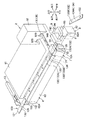
端子圧着装置1は、図1に示すように、アプリケータ2と、アプリケータ2の不図示のラムを昇降駆動させる不図示の駆動部と、駆動部を制御する不図示の制御部と、で構成されている。
続いて、端子圧着装置1を用いた端子圧着方法について、図12A〜図12Dを参照して説明する。図12A〜図12Dは、多芯ケーブル10を製造する手順を模式的に説明するための図である。詳細には、図12Aは、一対の端子13A、13Bが、端子ガイド6によって、端子リール(図示せず)からアンビル94の位置まで水平に案内される様子を示す図であり、図12Bは、第1連結部133が切断される様子を示す図であり、図12Cは、一対の端子13A、13Bのうち一方(端子13A)が他方(端子13B)に近付けられて位置決めされた状態を示す図であり、図12Dは、完成状態の多芯ケーブル10を示す平面図である。
7 キャリア切断ユニット(キャリア切断手段)
11 電線
13A 一対の端子のうち一方
13B 一対の端子のうち他方
71、72 一対の対向壁部(支持部)
94 アンビル(圧着型)
92 クリンパ(圧着型)
131 キャリア
132 端子接続部
133 第1連結部(連結部)
Claims (3)
- キャリアによって連結された複数の端子のうち、隣接する一対の端子それぞれに電線を圧着接続するための端子圧着装置であって、
前記キャリアは、各前記端子に接続される端子接続部と、隣接する前記端子接続部を連結する連結部と、を有し、
前記連結部を切断するキャリア切断手段と、
前記一対の端子のうち一方を他方に近付けて位置決めする端子位置決め手段と、
各前記端子と前記電線とを圧着接続するために対を成して構成された圧着型と、を備えたことを特徴とする端子圧着装置。 - 前記端子位置決め手段が、前記キャリアを、前記一方から前記他方に向けて送り出す端子送り手段を備え、
前記キャリア切断手段は、前記キャリアを前記一方から前記他方に向けて移動自在に支持する支持部と、前記支持部の前記一方から前記他方に向かう方向に並んで設けられて前記連結部を切断して少なくともその一部を切り取る一対の刃部と、を有していることを特徴とする請求項1に記載の端子圧着装置。 - キャリアによって連結された複数の端子のうち、隣接する一対の端子それぞれに電線を圧着接続するための端子圧着方法であって、
前記キャリアは、各前記端子に接続される端子接続部と、隣接する前記端子接続部を連結する連結部と、を有し、
前記一対の端子間に位置して前記一対の端子を連結した前記連結部を切断するキャリア切断工程と、
該キャリア切断工程にて切断分離された前記一対の端子のうち一方を他方に近付けて位置決めする端子位置決め工程と、
該端子位置決め工程で位置決めされた各前記端子と前記電線とを圧着接続する端子圧着工程と、を備えたことを特徴とする端子圧着方法。
Priority Applications (6)
| Application Number | Priority Date | Filing Date | Title |
|---|---|---|---|
| JP2018004333A JP6678688B2 (ja) | 2018-01-15 | 2018-01-15 | 端子圧着装置、及び、端子圧着方法 |
| MX2020006074A MX2020006074A (es) | 2018-01-15 | 2018-11-15 | Dispositivo de engaste de terminal y metodo de engaste de terminal. |
| US16/771,455 US11223177B2 (en) | 2018-01-15 | 2018-11-15 | Terminal crimping device |
| CN201880082040.1A CN111492543B (zh) | 2018-01-15 | 2018-11-15 | 端子压接装置和端子压接方法 |
| PCT/JP2018/042319 WO2019138687A1 (ja) | 2018-01-15 | 2018-11-15 | 端子圧着装置、及び、端子圧着方法 |
| DE112018006857.9T DE112018006857T5 (de) | 2018-01-15 | 2018-11-15 | Anschlusscrimpvorrichtung und Anschlusscrimpverfahren |
Applications Claiming Priority (1)
| Application Number | Priority Date | Filing Date | Title |
|---|---|---|---|
| JP2018004333A JP6678688B2 (ja) | 2018-01-15 | 2018-01-15 | 端子圧着装置、及び、端子圧着方法 |
Publications (2)
| Publication Number | Publication Date |
|---|---|
| JP2019125451A JP2019125451A (ja) | 2019-07-25 |
| JP6678688B2 true JP6678688B2 (ja) | 2020-04-08 |
Family
ID=67218919
Family Applications (1)
| Application Number | Title | Priority Date | Filing Date |
|---|---|---|---|
| JP2018004333A Active JP6678688B2 (ja) | 2018-01-15 | 2018-01-15 | 端子圧着装置、及び、端子圧着方法 |
Country Status (6)
| Country | Link |
|---|---|
| US (1) | US11223177B2 (ja) |
| JP (1) | JP6678688B2 (ja) |
| CN (1) | CN111492543B (ja) |
| DE (1) | DE112018006857T5 (ja) |
| MX (1) | MX2020006074A (ja) |
| WO (1) | WO2019138687A1 (ja) |
Family Cites Families (9)
| Publication number | Priority date | Publication date | Assignee | Title |
|---|---|---|---|---|
| JPH09306629A (ja) * | 1996-05-10 | 1997-11-28 | Yazaki Corp | 自動端子圧着装置 |
| JP3534230B2 (ja) * | 1998-09-07 | 2004-06-07 | 住友電装株式会社 | コネクタ |
| JP4113317B2 (ja) * | 2000-02-15 | 2008-07-09 | 矢崎総業株式会社 | 圧接コネクタ |
| JP3982480B2 (ja) * | 2003-10-31 | 2007-09-26 | 住友電装株式会社 | マルチ圧着装置及び端子供給モジュール |
| CN101350490A (zh) * | 2007-07-16 | 2009-01-21 | 汉达精密电子(昆山)有限公司 | 端子定位加裁切机构 |
| JP2010003429A (ja) * | 2008-06-18 | 2010-01-07 | Yazaki Corp | 多心電線の端子圧着方法 |
| JP2012238437A (ja) * | 2011-05-11 | 2012-12-06 | Sumitomo Electric Ind Ltd | 電線の圧着端子付け方法 |
| JP6125894B2 (ja) * | 2013-05-10 | 2017-05-10 | 矢崎総業株式会社 | 端子圧着電線製造装置及び端子圧着電線の製造方法 |
| CN111244726B (zh) * | 2018-11-29 | 2024-11-22 | 上海飞乐汽车控制系统有限公司 | 一种线束连接器安装装置 |
-
2018
- 2018-01-15 JP JP2018004333A patent/JP6678688B2/ja active Active
- 2018-11-15 CN CN201880082040.1A patent/CN111492543B/zh active Active
- 2018-11-15 WO PCT/JP2018/042319 patent/WO2019138687A1/ja not_active Ceased
- 2018-11-15 US US16/771,455 patent/US11223177B2/en not_active Expired - Fee Related
- 2018-11-15 MX MX2020006074A patent/MX2020006074A/es unknown
- 2018-11-15 DE DE112018006857.9T patent/DE112018006857T5/de active Pending
Also Published As
| Publication number | Publication date |
|---|---|
| MX2020006074A (es) | 2020-08-24 |
| CN111492543B (zh) | 2022-02-01 |
| US20200366042A1 (en) | 2020-11-19 |
| US11223177B2 (en) | 2022-01-11 |
| DE112018006857T5 (de) | 2020-09-24 |
| JP2019125451A (ja) | 2019-07-25 |
| WO2019138687A1 (ja) | 2019-07-18 |
| CN111492543A (zh) | 2020-08-04 |
Similar Documents
| Publication | Publication Date | Title |
|---|---|---|
| US10424891B2 (en) | Wire crimping device | |
| EP2169771B1 (en) | A terminal fitting, a terminal fitting chain, a wire with a terminal fitting, a processing device therefor and a connecting method therefor | |
| JP2015005521A5 (ja) | ||
| US3393438A (en) | Crimping tool | |
| CN101548443A (zh) | 端子压接装置 | |
| US11146033B2 (en) | Multicore cable manufacturing method | |
| CN114784589A (zh) | 端子压接装置 | |
| JPS6332230B2 (ja) | ||
| JP6678688B2 (ja) | 端子圧着装置、及び、端子圧着方法 | |
| EP0145416B1 (en) | Apparatus for making electrical harnesses | |
| CN109997284B (zh) | 端子保持件、端子压接装置及附带端子的绞合电线的制造方法 | |
| JP2004071237A (ja) | 電線の圧着装置 | |
| JP6949788B2 (ja) | 端子圧着装置及び端子圧着方法 | |
| JPH0745352A (ja) | 異種端子付テープおよび端子圧着機 | |
| JPH04355087A (ja) | 端子付電線の製造方法 | |
| CN110581423A (zh) | 端子压接装置和端子压接方法 | |
| JP2008066156A (ja) | 圧着端子 | |
| JP2009224079A (ja) | 内導体端子、連鎖端子、及び、同軸ケーブルと内導体端子との圧着接続方法 | |
| JPH10172712A (ja) | ワイヤ圧着ハーネスの製造装置と方法 | |
| JP2003077612A (ja) | ピッチ変換機構付き電線圧接装置 | |
| WO2013061633A1 (ja) | 端子圧着装置 | |
| JPH11185925A (ja) | 電源プラグ用端子圧着装置 | |
| JPH0577891U (ja) | 電源プラグ製造装置 | |
| JP2024131158A (ja) | 端子圧着装置及び端子の圧着方法 | |
| JP2024131159A (ja) | 端子圧着装置及び端子の圧着方法 |
Legal Events
| Date | Code | Title | Description |
|---|---|---|---|
| A621 | Written request for application examination |
Free format text: JAPANESE INTERMEDIATE CODE: A621 Effective date: 20190319 |
|
| TRDD | Decision of grant or rejection written | ||
| A01 | Written decision to grant a patent or to grant a registration (utility model) |
Free format text: JAPANESE INTERMEDIATE CODE: A01 Effective date: 20200310 |
|
| A61 | First payment of annual fees (during grant procedure) |
Free format text: JAPANESE INTERMEDIATE CODE: A61 Effective date: 20200317 |
|
| R150 | Certificate of patent or registration of utility model |
Ref document number: 6678688 Country of ref document: JP Free format text: JAPANESE INTERMEDIATE CODE: R150 |
|
| R250 | Receipt of annual fees |
Free format text: JAPANESE INTERMEDIATE CODE: R250 |
|
| S531 | Written request for registration of change of domicile |
Free format text: JAPANESE INTERMEDIATE CODE: R313531 |
|
| R350 | Written notification of registration of transfer |
Free format text: JAPANESE INTERMEDIATE CODE: R350 |
|
| R250 | Receipt of annual fees |
Free format text: JAPANESE INTERMEDIATE CODE: R250 |
|
| R250 | Receipt of annual fees |
Free format text: JAPANESE INTERMEDIATE CODE: R250 |