JP6626043B2 - Gaming machine - Google Patents
Gaming machine Download PDFInfo
- Publication number
- JP6626043B2 JP6626043B2 JP2017123056A JP2017123056A JP6626043B2 JP 6626043 B2 JP6626043 B2 JP 6626043B2 JP 2017123056 A JP2017123056 A JP 2017123056A JP 2017123056 A JP2017123056 A JP 2017123056A JP 6626043 B2 JP6626043 B2 JP 6626043B2
- Authority
- JP
- Japan
- Prior art keywords
- effect
- display
- meter
- period
- big hit
- Prior art date
- Legal status (The legal status is an assumption and is not a legal conclusion. Google has not performed a legal analysis and makes no representation as to the accuracy of the status listed.)
- Active
Links
Images


Description
本発明は、パチンコ遊技機やスロットマシン等の遊技機に関し、特に、変動表示を実行し、遊技者にとって有利な有利状態に制御可能な遊技機に関する。 The present invention relates to a gaming machine such as a pachinko gaming machine and a slot machine, and more particularly, to a gaming machine that executes a variable display and can be controlled to an advantageous state that is advantageous to a player.
このような遊技機としては、遊技者の連打動作の検出によりメータを上昇させ、メータが上限値に到達することにより、遊技者に有利な報知を行なうものがあった(特許文献1)。 As such a gaming machine, there has been a gaming machine which raises a meter by detecting a continuous hitting operation of a player and makes a notification advantageous to the player when the meter reaches an upper limit value (Patent Document 1).
しかし、特許文献1に記載された遊技機では、所定表示としてのメータが特定態様としての上限値に変化しなければ遊技者に有利な報知が行なわれることがなく、有利な報知のパターンが一様で面白みに欠けていた。
However, in the gaming machine described in
本発明は、かかる実情に鑑み考え出されたものであり、その目的は、所定表示が変化するパターンを多様化させ、遊技の興趣を向上する遊技機を提供することである。 The present invention has been conceived in view of the above circumstances, and an object of the present invention is to provide a gaming machine that diversifies a pattern in which a predetermined display changes and enhances the interest of a game.
(A) 変動表示を実行し、遊技者にとって有利な有利状態に制御可能な遊技機であって、
検出有効期間中における遊技者の動作を検出する動作検出手段と、
所定表示を表示する表示手段と、
前記所定表示が特定態様、または当該特定態様とは異なる特殊態様に変化したときに、遊技者に有利な報知を行なう報知手段とを備え、
前記表示手段は、
前記検出有効期間中において、前記動作検出手段の検出結果に基づいて、前記所定表示に第1作用演出を実行することにより、前記所定表示を前記特定態様に変化させる第1変化と、
前記検出有効期間中において、前記動作検出手段の検出結果に基づいて、前記所定表示に前記第1作用演出を実行した後に、前記検出有効期間が終了する前であって前記所定表示が前記特定態様に変化していないときに、前記動作検出手段の検出結果に基づいて、前記所定表示に前記第1作用演出とは異なる第2作用演出を実行することにより、前記所定表示を前記特殊態様に変化させる第2変化と、を実行可能である。
(1) 変動表示を実行し、遊技者にとって有利な有利状態(大当り遊技状態等)に制御可能な遊技機(パチンコ遊技機1等)であって、
遊技者の動作を検出する動作検出手段(プッシュボタン120、プッシュセンサ124等)と、
所定表示(メータ99等)を表示する表示手段(演出表示装置9等)と、
所定表示が特定態様(MAX態様等)に変化したときに、遊技者に有利な報知(大当り報知)を行なう報知手段(演出制御用マイクロコンピュータ100等)とを備え、
前記表示手段は、
前記動作検出手段の検出結果に基づいて、前記所定表示に第1作用演出を実行することにより、前記特定態様に変化させ(図12(d)に示すように、メータ99をMAXまで上昇させるメータMAX演出によりMAX態様に変化させる等)、
前記動作検出手段の検出結果に基づいて、前記所定表示に対して前記第1作用演出とは異なる作用を実行する第2作用演出を実行可能である(図12(e)に示すように、メータ99に亀裂が入るメータ破壊演出を実行する等)。
(A) A gaming machine that performs a variable display and can be controlled to an advantageous state advantageous to a player,
An operation detecting means for detecting an operation of the player during the detection valid period;
Display means for displaying a predetermined display;
When the predetermined display is changed to a specific mode or a special mode different from the specific mode, a notifying unit that performs a notification that is advantageous to the player,
The display means,
A first change that changes the predetermined display to the specific mode by executing a first action effect on the predetermined display based on a detection result of the operation detection unit during the detection valid period;
During the detection valid period, after the first action effect is performed on the predetermined display based on the detection result of the operation detecting means, before the detection valid period ends and the predetermined display is in the specific mode. The predetermined display is changed to the special mode by executing a second operation effect different from the first operation effect on the predetermined display based on the detection result of the operation detecting means when the predetermined display is not changed to And a second change to be performed.
(1) A gaming machine (such as a pachinko gaming machine 1) that performs variable display and can be controlled to an advantageous state (big hit gaming state or the like) advantageous to the player,
Operation detecting means (
Display means (
When the predetermined display changes to a specific mode (MAX mode or the like), a notification means (
The display means,
The first action effect is executed on the predetermined display based on the detection result of the operation detecting means to change to the specific mode (the
Based on the detection result of the operation detecting means, it is possible to execute a second action effect that performs an action different from the first action effect on the predetermined display (as shown in FIG. For example, a meter destruction effect that
このような構成によれば、所定表示が変化するパターンを多様化させ、遊技の興趣を向上させることができる。 According to such a configuration, the pattern in which the predetermined display changes can be diversified, and the interest of the game can be improved.
(2) 前記(1)の遊技機であって、
前記表示手段は、前記第2演出の実行に基づいて、前記所定表示の態様を前記特定態様とは異なる特殊態様に変化させ(図12(e)に示すように、メータ99に亀裂が入るメータ破壊演出により、破壊態様に変化する等)、
前記報知手段は、前記所定表示の態様が前記特殊態様に変化したことに基づいて、遊技者に有利な報知を行なう(図12(f)に示すように、メータ99が破壊態様となること
に基づいて、大当り報知を行なう等)。
(2) The gaming machine according to (1),
The display means changes the mode of the predetermined display to a special mode different from the specific mode based on the execution of the second effect (as shown in FIG. 12 (e), the
The notifying unit makes a notification that is advantageous to the player based on the change of the predetermined display mode to the special mode (as shown in FIG. 12F, the
このような構成によれば、所定表示が特殊態様に変化することに期待を持たせることができ、遊技の興趣を向上させることができる。 According to such a configuration, it can be expected that the predetermined display changes to a special mode, and the interest of the game can be improved.
(3) 前記(2)の遊技機であって、
前記特殊態様は、前記所定表示が前記第1演出によって前記特定態様となる前に変化し得る態様を経て表示される(図12(e),(f)に示すように、メータ99の表示は、MAX態様の1つ手前の態様を経て破壊態様となる等)。
(3) The gaming machine according to (2),
The special mode is displayed via a mode in which the predetermined display can be changed before the specific mode is changed to the specific mode (as shown in FIGS. 12E and 12F, the display of the
このような構成によれば、所定表示が特定態様に変化しない場合にも特殊態様により有利な報知が行なわれる場合があるので、遊技の興趣を向上させることができる。 According to such a configuration, even when the predetermined display does not change to the specific mode, an advantageous notification may be performed in the special mode, so that the interest of the game can be improved.
(4) 前記(2)または(3)の遊技機であって、
前記所定表示を前記特定態様に変化させるか前記特殊態様に変化させるかを、前記所定表示の態様を変化させるための前記動作検出手段での検出が可能となる前に決定する決定手段(図14のS632に示すように、メータ99をMAX態様とするか破壊態様とするかを、遊技者動作の検出が可能となる演出図柄変動中処理よりも前の演出図柄変動開始処理において決定する等)をさらに備える。
(4) The gaming machine according to (2) or (3),
Determining means for determining whether to change the predetermined display to the specific mode or the special mode before the operation detecting means for changing the mode of the predetermined display becomes possible (FIG. 14) As shown in S632, whether the
このような構成によれば、所定表示がいずれの態様に変化するかに注目させることができる。 According to such a configuration, attention can be paid to which mode the predetermined display changes.
(5) 前記(1)〜(4)の遊技機であって、
前記表示手段は、前記所定表示が前記第1演出によって前記特定態様となる前の途中態様となった後に、前記第2演出を実行可能である(図12(c),(e)に示すようなMAX態様となる1つ手前の途中態様である操作回数20回の上限値となった後に、図12(e)のような亀裂が入るメータ破壊演出を実行する等)。
(5) The gaming machine according to (1) to (4),
The display means is capable of executing the second effect after the predetermined display is in an intermediate state before the specific effect is achieved by the first effect (as shown in FIGS. 12C and 12E). After the upper limit value of the number of
このような構成によれば、途中態様となっても第2演出の実行に期待を持たせることができる。 According to such a configuration, expectations can be given to the execution of the second effect even in the middle mode.
(6) 前記(1)〜(5)の遊技機であって、
前記表示手段は、
前記動作検出手段により検出有効期間において遊技者が複数回の動作を行なう連続動作(プッシュボタン120の連打操作)が実行されたことに応じて前記第1演出および前記第2演出を実行可能であり(プッシュボタン120の連打操作によりメータMAX演出およびメータ破壊演出を実行する等)、
遊技者による前記連続動作とは異なる所定動作(プッシュボタン120の長押し操作)に基づいて、前記連続動作が実行されたとみなして前記第1演出および前記第2演出を実行可能であり(プッシュボタン120の長押し操作によりメータMAX演出およびメータ破壊演出を実行する等)、
前記検出有効期間において、所定期間(図18のオート連打開始可能期間等)が経過するまでは前記所定動作に基づいて前記連続動作が実行されたとみなし、当該所定期間が経過した後(図18のオート連打開始不可能期間等)に前記所定動作が開始されても前記連続動作が実行されたとみなさない。
(6) The gaming machine according to (1) to (5),
The display means,
The first effect and the second effect can be executed in response to execution of a continuous operation (continuous operation of the push button 120) in which the player performs a plurality of operations during the detection valid period by the operation detecting means. (Executing the meter MAX effect and the meter destruction effect by repeatedly operating the push button 120),
The first effect and the second effect can be executed based on a predetermined operation different from the continuous operation performed by the player (a long press operation of the push button 120), assuming that the continuous operation has been executed (
In the detection valid period, it is considered that the continuous operation has been performed based on the predetermined operation until a predetermined period (such as the auto continuous hit start possible period in FIG. 18) has elapsed, and after the predetermined period has elapsed (FIG. 18). Even if the predetermined operation is started during an automatic continuous-hit start impossible period, the continuous operation is not considered to be executed.
このような構成によれば、検出有効期間において所定期間が経過するか否かに基づいて、連続動作が実行されたとみなすか、みなさないかとすることにより、演出の面白みを向上させることができ、遊技者の興趣を向上させることができる。 According to such a configuration, based on whether or not a predetermined period elapses in the detection valid period, it is possible to improve the fun of the effect by regarding whether or not the continuous operation is performed or not. The interest of the player can be improved.
[第1実施形態]
以下、本発明の実施の形態を、図面を参照して説明する。まず、遊技機の一例であるパチンコ遊技機1の全体の構成について説明する。図1はパチンコ遊技機1を正面からみた正面図である。
[First Embodiment]
Hereinafter, embodiments of the present invention will be described with reference to the drawings. First, the overall configuration of the
パチンコ遊技機1は、遊技媒体としての遊技球を遊技領域7に打込んで遊技が行なわれる遊技機である。パチンコ遊技機1は、外枠と、外枠の内側に開閉可能に取付けられた遊技枠とで構成される。また、パチンコ遊技機1は、遊技枠に開閉可能に設けられているガラス扉枠2を有する。
The
ガラス扉枠2の下部表面には打球供給皿(上皿)3がある。打球供給皿3の下部には、打球供給皿3に収容しきれない遊技球を貯留する余剰球受皿4、および、打球を発射する打球操作ハンドル5等が設けられている。パチンコ遊技機1の内部には、打球操作ハンドル5の操作に応じて遊技領域7に遊技球を打込む打球発射装置が設けられている。ガラス扉枠2の背面には、遊技盤6が着脱可能に取付けられている。遊技盤6の前面には、打込まれた遊技球が流下可能な遊技領域7が形成されている。
On the lower surface of the
余剰球受皿(下皿)4を形成する部材には、下皿本体の上面における手前側の所定位置に、複数方向(前後左右)に傾倒する操作が可能なスティックコントローラ122が取付けられている。
A
打球供給皿(上皿)3を形成する部材には、上皿本体の上面における手前側の所定位置等に、遊技者が押下操作等により所定の指示操作を可能なプッシュボタン120が設けられている。プッシュボタン120の設置位置における上皿の本体内部等には、プッシュボタン120に対してなされた遊技者の操作行為(遊技者の動作)を検知するプッシュセンサ124(図3参照)が設けられている。
A
遊技領域7の中央付近には、各々を識別可能な複数種類の識別情報としての演出図柄を変動表示(可変表示ともいう)可能な表示手段としての演出表示装置9が設けられている。遊技領域7における演出表示装置9の右側方には、各々を識別可能な複数種類の識別情報としての第1特別図柄を変動表示する第1特別図柄表示器(第1変動表示部)8aと、各々を識別可能な複数種類の識別情報としての第2特別図柄を変動表示する第2特別図柄表示器(第2変動表示部)8bとが設けられている。
In the vicinity of the center of the
第1特別図柄表示器8aおよび第2特別図柄表示器8bのそれぞれは、数字および文字を変動表示可能な簡易で小型の表示器(たとえば7セグメントLED)で構成されている。演出表示装置9は、液晶表示装置(LCD)で構成されており、表示画面において、第1特別図柄または第2特別図柄の変動表示に同期した演出図柄の変動表示を行なう演出図柄表示領域が設けられる。演出図柄表示領域には、たとえば左,中,右の3つの装飾用(演出用)の演出図柄を変動表示する図柄表示エリアが形成される。以下、第1特別図柄と第2特別図柄とを特別図柄と総称することがあり、第1特別図柄表示器8aと第2特別図柄表示器8bとを特別図柄表示器(変動表示部)と総称することがある。
Each of the first
第1特別図柄表示器8aおよび第2特別図柄表示器8bのそれぞれは、主基板(遊技制御基板)に搭載されている遊技制御用マイクロコンピュータによって制御される。演出表示装置9は、演出制御基板に搭載されている演出制御用マイクロコンピュータによって制御される。第1特別図柄表示器8aで第1特別図柄の変動表示が実行されているときに、その変動表示に伴なって演出表示装置9で演出表示が実行され、第2特別図柄表示器8bで第2特別図柄の変動表示が実行されているときに、その変動表示に伴なって演出表示装置9で演出表示が実行されるので、遊技の進行状況を把握しやすくすることができる。
Each of the first
第1特別図柄表示器8aに特定表示結果としての大当り表示結果(大当り図柄)が導出表示されたとき、または、第2特別図柄表示器8bに特定表示結果としての大当り表示結果(大当り図柄)が導出表示されたときには、演出表示装置9においても、特定表示結果としての大当り表示結果(大当り図柄の組合せ)が導出表示される。このように変動表示の表示結果として特定表示結果が表示されたときには、遊技者にとって有利な価値(有利価値)が付与される有利状態としての特定遊技状態(大当り遊技状態)に制御される。
When the big hit display result (big hit symbol) as the specific display result is derived and displayed on the first
また、演出表示装置9において、最終停止図柄(たとえば左右中図柄のうち中図柄)となる図柄以外の図柄が、所定時間継続して、大当り図柄(たとえば左中右の図柄が同じ図柄で揃った図柄の組合せ)と一致している状態で停止、揺動、拡大縮小もしくは変形している状態、または、複数の図柄が同一図柄で同期して変動表示したり、表示図柄の位置が入れ替わっていたりして、最終結果が表示される前で大当り発生の可能性が継続している状態(以下、これら状態をリーチ状態という。)で行なわれる演出をリーチ演出という。
Further, in the
演出表示装置9の下方には、第1始動入賞口13を有する入賞装置が設けられている。第1始動入賞口13に入賞した遊技球は、遊技盤6の背面に導かれ、第1始動口スイッチ13aによって検出される。また、第1始動入賞口(第1始動口)13を有する入賞装置の下方には、遊技球が入賞可能な第2始動入賞口14を有する可変入賞球装置15が設けられている。第2始動入賞口(第2始動口)14に入賞した遊技球は、遊技盤6の背面に導かれ、第2始動口スイッチ14aによって検出される。
Below the
可変入賞球装置15は、ソレノイド16によって開状態とされる。可変入賞球装置15が開状態になることによって、遊技球が第2始動入賞口14に入賞可能になり(始動入賞し易くなり)、遊技者にとって有利な状態になる。また、可変入賞球装置15が閉状態になっている状態では、遊技球は第2始動入賞口14に入賞しない。以下、第1始動入賞口
13と第2始動入賞口14とを総称して始動入賞口または始動口ということがある。
The variable winning
第2特別図柄表示器8bの上方には、第2始動入賞口14に入った有効入賞球数すなわち第2保留記憶数を表示する4つの表示器からなる第2特別図柄保留記憶表示器18bが設けられている。また、第2特別図柄保留記憶表示器18bのさらに上方には、第1始動入賞口13に入った有効入賞球数すなわち第1保留記憶数を表示する4つの表示器からなる第1特別図柄保留記憶表示器18aが設けられている。
Above the second
遊技機には、遊技者が打球操作ハンドル5を操作することに応じて駆動モータを駆動し、駆動モータの回転力を利用して遊技球を遊技領域7に発射する打球発射装置が設けられている。打球発射装置から発射された遊技球は、遊技領域7を囲むように円形状に形成された打球レールを通って遊技領域7に入り、その後、遊技領域7を下りてくる。
The gaming machine is provided with a hit ball launching device that drives a drive motor in response to the player operating the hit ball operation handle 5 and uses the rotational force of the drive motor to shoot game balls into the
演出表示装置9の表示画面における下部の位置には、第1保留記憶数と第2保留記憶数との合計数(合算保留記憶数)を表示する保留記憶表示部(合算保留記憶表示部、保留表示エリア、図示せず)が設けられる。合算保留記憶表示部では、保留記憶表示として保留記憶数をたとえば所定画像の表示個数により特定可能な保留記憶画像(保留記憶情報のそれぞれに対応して1つずつ保留記憶画像を表示することにより、保留記憶数を特定する。)が表示される。第1特別図柄保留記憶表示器18a、第2特別図柄保留記憶表示器18b、および、演出表示装置9のそれぞれにおいて、保留記憶数を示すための発光表示および画像表示は、保留表示、または、保留記憶表示と呼ばれる。
At the lower position on the display screen of the
可変入賞球装置15の下方には、特別可変入賞球装置20が設けられている。特別可変入賞球装置20は開閉板を備え、第1特別図柄表示器8aに特定表示結果(大当り図柄)が導出表示されたときと、第2特別図柄表示器8bに特定表示結果(大当り図柄)が導出表示されたときに生起する特定遊技状態(大当り遊技状態)においてソレノイド21によって開閉板が開放状態に制御されることによって、入賞領域となる大入賞口が開放状態になる。大入賞口に入賞した遊技球はカウントスイッチ23で検出される。
A special variable winning
大当り遊技状態では、特別可変入賞球装置20が開放状態と閉鎖状態とを繰返す繰返し継続制御が行なわれる。繰返し継続制御において、特別可変入賞球装置20が開放されている状態が、ラウンドと呼ばれる。繰返し継続制御は、ラウンド制御とも呼ばれる。
In the big hit game state, the repetition continuation control in which the special variable winning
演出表示装置9の左方には、各々を識別可能な普通図柄を変動表示する普通図柄表示器10が設けられている。普通図柄表示器10の近傍には、ゲート32を通過した入賞球数を表示する4つのLEDによる表示部を有する普通図柄保留記憶表示器41が設けられている。
On the left side of the
演出表示装置9の上方には、役物12が設けられている。役物12は、遊技盤6と演出表示装置9との間に位置し、役物モータ17によって位置を変位することが可能である。役物12は、通常は遊技者から視認し難い場所に位置し、所定の演出が実行されるときに遊技者から視認可能な位置(たとえば、演出表示装置9の前方の位置)に移動する。
An
遊技盤6の下部には、入賞しなかった打球が取込まれるアウト口26がある。また、遊技領域7の外側の左右上部および左右下部には、所定の音声出力として効果音や音声を発声する4つのスピーカ27が設けられている。遊技領域7の外周には、前面枠に設けられた枠LED28が設けられている。
At the lower part of the
図2の当り種別表においては、大当りにおける当りの種別ごとに、大当り遊技状態の終了後の大当り確率、大当り遊技状態の終了後のベース、大当り遊技状態終了後の変動時間
、大当りにおける開放回数、および、各ラウンドの開放時間が示されている。
In the hit type table of FIG. 2, the big hit probability after the end of the big hit game state, the base after the big hit game state ends, the fluctuation time after the big hit game state end, the number of open times in the big hit, The opening time of each round is shown.
「大当り」のうち、大当り遊技状態に制御された後、特別遊技状態として、通常状態(確変状態でない通常の遊技状態)に比べて大当りとすることに決定される確率が高い状態である確変状態(確率変動状態の略語であり、高確率状態ともいう)に移行する大当りの種類(種別)は、「確変大当り」と呼ばれる。また、本実施の形態では、特別遊技状態としては、確変状態に付随して、特別図柄や演出図柄の変動時間(変動表示期間)が非時短状態よりも短縮される時短状態に制御される場合がある。なお、特別遊技状態としては、確変状態とは独立して時短状態に制御される場合があるようにしてもよい。 Of the "big hits", after being controlled to the big hitting game state, the probable state in which the special game state is a state where the probability of being determined to be the big hit is higher than the normal state (the normal game state which is not the probable state). The type (type) of the big hit that shifts to (probability abbreviated state and also referred to as a high probability state) is called a “probable big hit”. In the present embodiment, the special game state is controlled to a time reduction state in which the fluctuation time (variation display period) of the special symbol or the effect symbol is shortened compared to the non-time reduction state, in association with the probability change state. There is. Note that the special game state may be controlled to the time saving state independently of the probability change state.
時短状態に移行することによって、特別図柄や演出図柄の変動時間が短縮されるので、時短状態となったときには、有効な始動入賞が発生しやすくなり大当り遊技が行なわれる可能性が高まる。なお、「大当り」のうち、15ラウンドの大当り遊技状態に制御された後、確変状態に移行しない大当りの種類(種別)は、「通常大当り」と呼ばれる。 By shifting to the time saving state, the fluctuation time of the special symbol and the effect symbol is reduced, so that when the time saving state is reached, an effective start winning is easily generated and the possibility of a big hit game is increased. It should be noted that, among the “big hits”, the type (type) of the big hit that does not shift to the probable change state after being controlled to the big hit gaming state of 15 rounds is called “normal big hit”.
また、特別遊技状態としては、確変状態または時短状態に付随して、可変入賞球装置15が開状態になる頻度を高くすることにより可変入賞球装置15に遊技球が進入する頻度を高くして可変入賞球装置15への入賞を容易化(高進入化、高頻度化)する電チューサポート制御状態に制御される場合がある。電チューサポート制御状態は、高ベース状態であるので、以下の説明においては、主として高ベース状態と呼ぶ。
In addition, as a special game state, the frequency of the variable
電チューサポート制御としては、普通図柄の変動時間(変動表示開始時から表示結果の導出表示時までの時間)を短縮して早期に表示結果を導出表示させる制御(普通図柄短縮制御)、普通図柄の停止図柄が当り図柄になる確率を高める制御(普通図柄確変制御)、可変入賞球装置15の開放時間を長くする制御(開放時間延長制御)、および、可変入賞球装置15の開放回数を増加させる制御(開放回数増加制御)が行なわれる。このような制御が行なわれると、当該制御が行なわれていないときと比べて、可変入賞球装置15が開状態となっている時間比率が高くなるので、第2始動入賞口14への入賞頻度が高まり、遊技球が始動入賞しやすくなる。この制御によって第2始動入賞口14への入賞頻度が高まることにより、第2始動条件の成立頻度および/または第2特別図柄の変動表示の実行頻度が高まる遊技状態となる。
The control of the electric chew support includes a control for shortening the fluctuation time of the normal symbol (the time from the start of the fluctuation display to the time of deriving and displaying the display result) to quickly derive and display the display result (normal symbol shortening control), and a normal symbol. Control to increase the probability that the stopped symbol becomes a hit symbol (normal symbol probability change control), control to extend the opening time of the variable winning ball device 15 (opening time extension control), and increase the number of times the variable winning
電チューサポート制御により第2始動入賞口14への入賞頻度が高められた状態(高頻度状態)は、発射球数に対して入賞に応じて賞球として払出される遊技球数の割合である「ベース」が、当該制御が行なわれないときと比べて、高い状態であるので、「高ベース状態」と呼ばれる。また、このような制御が行なわれないときは、「低ベース状態」と呼ばれる。また、このような制御は、可変入賞球装置15、すなわち、電動チューリップにより入賞をサポートすることにより可変入賞球装置15への入賞を容易化する制御であり、「電チューサポート制御」と呼ばれる。
The state in which the winning frequency to the second
図2は当り種別表である。図2に示すように、当り種別、当り後大当り確率、当り後ベース、当り後変動時間、開放回数、および、ラウンド開放時間が設定されている。 FIG. 2 is a hit type table. As shown in FIG. 2, a hit type, a hit big hit probability, a hit hit base, a hit hit variation time, a release count, and a round release time are set.
図3は、主基板(遊技制御基板)および演出制御基板における回路構成の一例を示すブロック図である。図3には、払出制御基板37等も示されている。主基板31には、プログラムにしたがってパチンコ遊技機1を制御する遊技制御用マイクロコンピュータ(遊技制御手段に相当)560が搭載されている。遊技制御用マイクロコンピュータ560は、ゲーム制御(遊技進行制御)用のプログラム等を記憶するROM54、ワークメモリとして使用される記憶手段としてのRAM55、プログラムにしたがって制御動作を行なうCPU56およびI/Oポート部57を含む。遊技制御用マイクロコンピュータ560は、
ROM54およびRAM55が内蔵された1チップマイクロコンピュータである。遊技制御用マイクロコンピュータ560には、さらに、ハードウェア乱数(ハードウェア回路が発生する乱数)を発生する乱数回路503が内蔵されている。
FIG. 3 is a block diagram illustrating an example of a circuit configuration of the main board (game control board) and the effect control board. FIG. 3 also shows a
This is a one-chip microcomputer in which a
RAM55は、その一部または全部が電源基板において作成されるバックアップ電源によってバックアップされている不揮発性記憶手段としてのバックアップRAMである。すなわち、遊技機に対する電力供給が停止しても、所定期間(バックアップ電源としてのコンデンサが放電してバックアップ電源が電力供給不能になるまで)は、RAM55の一部または全部の内容は保存される。
The
乱数回路503は、特別図柄の変動表示の表示結果により大当りとするか否か判定するための判定用の乱数を発生するために用いられるハードウェア回路である。乱数回路503は、初期値(たとえば、0)と上限値(たとえば、65535)とが設定された数値範囲内で、数値データを設定された更新規則にしたがって更新し、ランダムなタイミングで発生する始動入賞時が数値データの読出(抽出)時であることに基づいて、読出される数値データが乱数値となる乱数発生機能を有する。遊技制御用マイクロコンピュータ560は、乱数回路503が更新する数値データの初期値を設定する機能を有している。
The
また、ゲートスイッチ32a、第1始動口スイッチ13a、第2始動口スイッチ14a、カウントスイッチ23からの検出信号を遊技制御用マイクロコンピュータ560に与える入力ドライバ回路58も主基板31に搭載されている。また、可変入賞球装置15を開閉するソレノイド16、および大入賞口を形成する特別可変入賞球装置20を開閉するソレノイド21を遊技制御用マイクロコンピュータ560からの指令にしたがって駆動する出力回路59も主基板31に搭載されている。
Further, an
また、遊技制御用マイクロコンピュータ560は、特別図柄を変動表示する第1特別図柄表示器8a、第2特別図柄表示器8b、普通図柄を変動表示する普通図柄表示器10、第1特別図柄保留記憶表示器18a、第2特別図柄保留記憶表示器18bおよび普通図柄保留記憶表示器41の表示制御を行なう。
Further, the
演出制御基板80は、演出制御用マイクロコンピュータ100、ROM102、RAM103、VDP109、および、I/Oポート部105等を搭載している。ROM102は、表示制御等の演出制御用のプログラムおよびデータ等を記憶する。RAM103は、ワークメモリとして使用される。ROM102およびRAM103は、演出制御用マイクロコンピュータ100に内蔵されてもよい。VDP109は、演出制御用マイクロコンピュータ100と共動して演出表示装置9の表示制御を行なう。
The
演出制御用マイクロコンピュータ100は、主基板31から演出制御基板80の方向への一方向にのみ信号を通過させる中継基板77を介して、遊技制御用マイクロコンピュータ560から演出内容を指示する演出制御コマンドを受信し、演出表示装置9の変動表示制御を行なう他、ランプドライバ基板35を介して、枠側に設けられている枠LED28の表示制御を行なうとともに、音声出力基板70を介してスピーカ27からの音出力の制御を行なう等、各種の演出制御を行なう。
The
また、演出制御用CPU101は、プッシュボタン120に対する遊技者の操作行為を検出したことを示す情報信号としての操作検出信号を、プッシュセンサ124から、I/Oポート部105の入力ポートを介して入力する。また、演出制御用CPU101は、モータ駆動回路を介して役物モータ17を駆動して役物12を動作させる。
The
図4は、各乱数を示す説明図である。図4においては、乱数の種別、更新範囲、用途、
および、加算条件が示されている。
FIG. 4 is an explanatory diagram showing each random number. In FIG. 4, the type of random number, update range, use,
In addition, addition conditions are shown.
図5は、大当り判定テーブルおよび大当り種別判定テーブルを示す説明図である。図5(A)は、大当り判定テーブルを示す説明図である。大当り判定テーブルとは、ROM54に記憶されているデータの集まりであって、ランダムRと比較される大当り判定値が設定されているテーブルである。大当り判定テーブルには、通常状態(確変状態でない遊技状態、すなわち非確変状態)において用いられる通常時(非確変時)大当り判定テーブルと、確変状態において用いられる確変時大当り判定テーブルとがある。
FIG. 5 is an explanatory diagram showing a big hit determination table and a big hit type determination table. FIG. 5A is an explanatory diagram showing a big hit determination table. The big hit determination table is a set of data stored in the
図5(B),(C)は、ROM54に記憶されている大当り種別判定テーブルを示す説明図である。図5(B)は、遊技球が第1始動入賞口13に入賞したことに基づく保留記憶(第1保留記憶ともいう)を用いて大当り種別を決定する場合(第1特別図柄の変動表示が行なわれるとき)に用いる第1特別図柄大当り種別判定テーブル(第1特別図柄用)である。図5(C)は、遊技球が第2始動入賞口14に入賞したことに基づく保留記憶(第2保留記憶ともいう)を用いて大当り種別を決定する場合(第2特別図柄の変動表示が行なわれるとき)に用いる第2特別図柄大当り種別判定テーブルである。
FIGS. 5B and 5C are explanatory diagrams showing the jackpot type determination tables stored in the
図6は、変動パターンを決定するために用いる変動パターンテーブルを表形式で示す図である。図6には、(a)に通常状態はずれ時判定テーブル、(b)に時短状態はずれ時判定テーブルが示されている。また、(c)に通常大当り時判定テーブル、(d)に確変大当り時判定テーブルが示されている。図6(a)〜(d)の各判定テーブルは、ROM54に記憶されており、遊技状態に応じて選択され、変動パターン種別および変動パターンを判定(決定)するために用いられる。
FIG. 6 is a diagram showing, in a table form, a variation pattern table used for determining a variation pattern. FIG. 6A shows a determination table for when the normal state has been lost, and FIG. 6B shows a determination table for when the time reduction state has been lost. (C) shows a normal big hit determination table, and (d) shows a positive change big hit determination table. Each of the determination tables in FIGS. 6A to 6D is stored in the
図6の各テーブルでの「ノーマルリーチ」は、リーチ状態となったときに特に派手な演出を実行しないノーマルリーチの変動パターンを示している。「スーパーリーチ」は、リーチ状態となったときに特別な演出画像を表示するリーチ演出を行なう変動パターンを示している。また、「スーパーリーチ」は、「ノーマルリーチ」と比べて大当りとなるときに選択される割合が高く、大当りとなる信頼度が高い変動パターンである。「スーパーリーチ」は、「ノーマルリーチ」と比べて変動時間が長い変動パターンである。スーパーリーチには、4種類の変動パターンが設定されており、第1スーパーリーチ<第2スーパーリーチ<第3スーパーリーチ<第4スーパーリーチとなるような関係で大当り期待度(大当りとなる可能性)が高いことを示す。 “Normal reach” in each table in FIG. 6 indicates a fluctuation pattern of a normal reach that does not execute a particularly fancy effect when it reaches the reach state. “Super reach” indicates a fluctuation pattern for performing a reach effect of displaying a special effect image when a reach state is attained. In addition, “super reach” is a variation pattern in which the ratio selected when a big hit is high and the reliability of the big hit is high compared to “normal reach”. “Super reach” is a fluctuation pattern having a longer fluctuation time than “normal reach”. Four types of fluctuation patterns are set for the super reach, and the big hit expectation (possibility of a big hit) in the relationship of 1st super reach <2nd super reach <3rd super reach <4th super reach ) Is high.
なお、“期待度”とは、大当りに対する期待度、確変に対する期待度等を含む概念である。具体的には、大当りに対する期待度(信頼度ともいう)とは、各リーチ変動パターンが選択された場合に大当りとなる期待度(大当りとなる割合)であり、たとえば、リーチ変動が100回行なわれた場合に60回大当りとなるのであれば、大当りに対する期待度が60%(大当りが出現する出現率(確率)が60%)となる。また、確変に対する期待度とは、確変状態に移行する期待度(確変となる割合)のことをいう。 The “expectation” is a concept including an expectation for a jackpot, an expectation for a probability change, and the like. Specifically, the degree of expectation (also referred to as reliability) for a big hit is an expectation (a rate of a big hit) that becomes a big hit when each reach variation pattern is selected. For example, the reach change is performed 100 times. If a big hit occurs 60 times in the event of a hit, the degree of expectation for the big hit is 60% (the appearance rate (probability) of the big hit appearance is 60%). Further, the degree of expectation for the probability change means the degree of expectation for shifting to the probability change state (rate of probability change).
図7は、遊技制御用マイクロコンピュータ560が送信する演出制御コマンドの内容の一例を示す説明図である。遊技制御用マイクロコンピュータ560においては、図7に示すように、遊技制御状態に応じて、各種の演出制御コマンドを演出制御用マイクロコンピュータ100へ送信する。
FIG. 7 is an explanatory diagram showing an example of the contents of an effect control command transmitted by the
次に、遊技制御用マイクロコンピュータ560側での保留記憶に対応する乱数等のデータ(保留記憶データ)を保存する領域(保留記憶バッファ)の構成例を説明する。保留記憶バッファは、RAM55に設けられる。
Next, a configuration example of an area (hold storage buffer) for storing data such as random numbers (hold storage data) corresponding to hold storage on the
第1保留記憶バッファには、第1保留記憶数の上限値(この例では4)に対応した保存領域が確保されている。また、第2保留記憶バッファには、第2保留記憶数の上限値(この例では4)に対応した保存領域が確保されている。第1保留記憶バッファおよび第2保留記憶バッファには、ハードウェア乱数である大当り判定用乱数(ランダムR)、および、ソフトウェア乱数である大当り種別決定用乱数(ランダム1)、変動パターン種別判定用乱数(ランダム2)、および、変動パターン判定用乱数(ランダム3)が記憶される。 In the first reserved storage buffer, a storage area corresponding to the upper limit value (4 in this example) of the first reserved storage number is secured. In the second reserved storage buffer, a storage area corresponding to the upper limit value (4 in this example) of the second reserved storage number is secured. The first hold storage buffer and the second hold storage buffer include a jackpot determination random number (random R) as a hardware random number, a jackpot type determination random number (random 1) as a software random number, and a variation pattern type determination random number. (Random 2) and a random number for determining a fluctuation pattern (Random 3) are stored.
次に、パチンコ遊技機1の動作について説明する。パチンコ遊技機1においては、主基板31における遊技制御用マイクロコンピュータ560が予め定められたメイン処理を実行すると、所定時間(たとえば2ms)毎に定期的にタイマ割込がかかりタイマ割込処理が実行されることにより、各種の遊技制御が実行可能となる。
Next, the operation of the
メイン処理においては、必要な初期設定処理、通常時の初期化処理、通常時以外の遊技状態復旧処理、乱数回路設定処理(乱数回路503を初期設定)、表示用乱数更新処理(変動パターンの種別決定、変動パターン決定等の各種乱数の更新処理)、および、初期値用乱数更新処理(普通図柄当り判定用乱数発生カウンタのカウント値の初期値の更新処理)等が実行される。 In the main processing, necessary initial setting processing, normal-time initialization processing, non-normal-time game state restoring processing, random number circuit setting processing (initial setting of the random number circuit 503), display random number updating processing (type of variation pattern) An update process of various random numbers such as determination, change pattern determination, and the like, and an initial value random number update process (an update process of the initial value of the count value of the normal random number generation counter for symbol hit determination) and the like are executed.
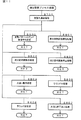
図8は、タイマ割込処理を示すフローチャートである。タイマ割込が発生すると、CPU56は、図8に示すステップS(以下、単に「S」と示す)20〜S34のタイマ割込処理を実行する。
FIG. 8 is a flowchart showing the timer interrupt processing. When a timer interrupt occurs, the
図9は、特別図柄プロセス処理(S26)を示すフローチャートである。特別図柄プロセス処理では、第1特別図柄表示器8aまたは第2特別図柄表示器8bおよび大入賞口を制御するための処理が実行される。特別図柄プロセス処理においては、始動口スイッチ通過処理を実行する(S312)。そして、内部状態に応じて、S300〜S307のうちのいずれかの処理を行なう。
FIG. 9 is a flowchart showing the special symbol process (S26). In the special symbol process processing, processing for controlling the first
始動口スイッチ通過処理では、第1始動口スイッチ13a(第2始動口スイッチ14a)がオンしていれば、第1保留記憶数(第2保留記憶数)が上限値(たとえば、4)に達していないことを条件として、第1保留記憶データ(第2保留記憶データ)の記憶数を計数する第1保留記憶数カウンタ(第2保留記憶数カウンタ)の値を1増やし、乱数回路503やソフトウェア乱数を生成するためのカウンタから数値データ(たとえば、大当り判定用乱数、変動パターン種別判定用乱数、および、変動パターン判定用乱数)を抽出し、それらを、第1保留記憶バッファ(第2保留記憶バッファ)における保存領域に保存(格納)する処理を実行する。さらに、合算保留記憶数カウンタの値を1増やし、合算後の合算保留記憶数カウンタの値に対応した保留特定領域に「第1(第2)」を示すデータを保存(格納)する処理を実行する。
In the starting port switch passing process, if the first
S300〜S307の処理は、以下のような処理である。特別図柄通常処理(S300)は、変動表示の表示結果を大当りとするか否かの決定、および、大当りとする場合の大当り種別の決定等を行なう処理である。変動パターン設定処理(S301)は、変動パターンの決定(変動パターン種別判定用乱数および変動パターン判定用乱数を用いた変動パターンの決定)、および、決定された変動パターンに応じて変動時間を計時するための変動時間タイマの計時開始等の制御を行なう処理である。 The processing of S300 to S307 is the following processing. The special symbol normal process (S300) is a process of determining whether or not the display result of the variable display is a big hit, and determining a big hit type in the case of a big hit. The variation pattern setting process (S301) determines a variation pattern (determines a variation pattern using a variation pattern type determination random number and a variation pattern determination random number), and counts a variation time according to the determined variation pattern. This is a process for controlling the start of time measurement of the variable time timer.
表示結果指定コマンド送信処理(S302)は、演出制御用マイクロコンピュータ100に、表示結果指定コマンドを送信する制御を行なう処理である。特別図柄変動中処理(S303)は、変動パターン設定処理で選択された変動パターンの変動時間が経過すると特別図柄停止処理にプロセスを進める処理である。特別図柄停止処理(S304)は、決
定された変動パターンに対応する変動時間の経過が変動時間タイマにより計時されたときに第1特別図柄表示器8aまたは第2特別図柄表示器8bにおける変動表示を停止して停止図柄を導出表示させる処理である。
The display result designation command transmission process (S302) is a process for controlling transmission of the display result designation command to the
大入賞口開放前処理(S305)は、大当りの種別に応じて、特別可変入賞球装置20において大入賞口を開放する制御等を行なう処理である。大入賞口開放中処理(S306)は、大当り遊技状態中のラウンド表示演出用の演出制御コマンドを演出制御用マイクロコンピュータ100に送信する制御、および、大入賞口の閉成条件の成立を確認する処理等を行なう処理である。大入賞口の閉成条件が成立し、かつ、まだ残りラウンドがある場合には、大入賞口開放前処理(S305)に移行する。また、全てのラウンドを終えた場合には、大当り終了処理(S307)に移行する。大当り終了処理(S307)は、大当り遊技状態が終了したことを遊技者に報知する表示制御を演出制御用マイクロコンピュータ100に行なわせるための制御等を行なう処理である。
The special winning opening process (S305) is a process for controlling the special winning opening in the special variable winning
次に、演出制御用マイクロコンピュータ100の動作を説明する。図10は、演出制御基板80に搭載されている演出制御用マイクロコンピュータ100(具体的には、演出制御用CPU101)が実行する演出制御メイン処理を示すフローチャートである。
Next, the operation of the
演出制御用CPU101は、電源が投入されると、演出制御メイン処理の実行を開始する。演出制御メイン処理では、まず、RAM領域のクリアや各種初期値の設定、また演出制御の起動間隔(たとえば、2ms)を決めるためのタイマの初期設定等を行なうための初期化処理を行なう(S701)。その後、演出制御用CPU101は、タイマ割込フラグの監視(S702)を行なうループ処理に移行する。タイマ割込が発生すると、演出制御用CPU101は、タイマ割込処理においてタイマ割込フラグをセットする。演出制御メイン処理において、タイマ割込フラグがセットされていたら、演出制御用CPU101は、そのフラグをクリアし(S703)、以下の演出制御処理を実行する。
When the power is turned on, the
演出制御処理において、演出制御用CPU101は、まず、受信した演出制御コマンドを解析し、受信した演出制御コマンドがどのようなことを指示するコマンドであるかを特定可能なフラグ等のデータをセットする処理(たとえば、RAM103に設けられた各種コマンド格納領域に受信したコマンドを特定可能なデータを格納する処理等)等を行なう(コマンド解析処理:S704)。次いで、演出制御用CPU101は、演出制御プロセス処理を行なう(S705)。演出制御プロセス処理では、S704で解析した演出制御コマンドの内容にしたがって演出表示装置9での演出図柄の変動表示等の各種演出を行なうために、制御状態に応じた各プロセスのうち、現在の制御状態(演出制御プロセスフラグ)に対応した処理を選択して演出制御を実行する。次いで、演出制御用マイクロコンピュータ100が用いる乱数を生成するためのカウンタのカウント値を更新する乱数更新処理を実行する(S706)。
In the production control process, the
次いで、保留表示エリアにおける保留表示の表示状態の制御(保留表示の移動、消去等)を行なう保留記憶表示制御処理を実行する(S707)。保留記憶表示制御処理では、保留表示やアクティブ表示の表示に関する処理が実行される。たとえば、保留表示として、演出表示装置9の表示領域において、第1保留記憶数と、第2保留記憶数との合計数を示す合算保留記憶表示部が形成される。
Next, a hold storage display control process for controlling the display state of the hold display in the hold display area (moving or deleting the hold display, etc.) is executed (S707). In the hold storage display control processing, processing relating to the display of the hold display and the active display is executed. For example, as the suspension display, in the display area of the
このような演出制御メイン処理が実行されることにより、演出制御用マイクロコンピュータ100では、遊技制御用マイクロコンピュータ560から送信され、受信した演出制御コマンドに応じて、演出表示装置9、各種ランプ、および、スピーカ27L,27R等の演出装置を制御することにより、遊技状態に応じた各種の演出制御が行なわれる。
By executing such an effect control main process, in the
図11は、図10に示された演出制御メイン処理における演出制御プロセス処理(S705)を示すフローチャートである。演出制御プロセス処理では、演出制御用CPU101は、先読み演出を実行するか否かの決定、および、先読み演出の種類の選択をする先読み演出処理(S700)を実行した後、演出制御プロセスフラグの値に応じてS800〜S807のうちのいずれかの処理を行なう。
FIG. 11 is a flowchart showing an effect control process (S705) in the effect control main process shown in FIG. In the effect control process, the
演出制御プロセス処理では、以下のような処理が実行される。演出制御プロセス処理では、演出表示装置9の表示状態が制御され、演出図柄の変動表示が実現されるが、第1特別図柄の変動に同期した演出図柄の変動表示に関する制御も、第2特別図柄の変動に同期した演出図柄の変動表示に関する制御も、一つの演出制御プロセス処理において実行される。
In the effect control process processing, the following processing is executed. In the effect control process, the display state of the
先読み演出処理(S700)は、先読み演出を実行するか否か等の先読み判定、および、先読み演出を実行するときの演出態様の決定等を行なう処理である。先読み演出とは、ある保留情報(保留記憶情報)に基づいた特別図柄の変動表示(図柄変動)の順番が到来する前に、その保留情報を先読みしてその保留情報に基づいた特別図柄の変動表示の内容を判定して、将来の特別図柄の変動表示がどのようになるかを、それよりも前の段階で予告をする等の演出技術である。たとえば、保留情報が大当りであるときに、当該保留情報による変動表示が実行される前に、当該保留情報に対応する保留表示の表示態様に基づいて、後に大当りが発生する可能性のあることを予告するといった類の演出が先読み演出として行なわれる。以下では、先読み演出の対象とした保留情報に基づいた変動表示を「ターゲットの変動表示」と称する。 The pre-reading effect process (S700) is a process of performing pre-reading determination, such as whether or not to execute a pre-reading effect, and determining an effect mode when executing the pre-reading effect. The look-ahead effect refers to pre-reading the hold information before the order of the change display (symbol change) of the special symbol based on certain hold information (hold storage information) and changing the special symbol based on the hold information This is an effect technique in which the content of the display is determined and a notice is given at an earlier stage of how the special symbol will be changed in the future. For example, when the hold information is a big hit, before the variable display based on the hold information is executed, a big hit may be generated later based on the display mode of the hold display corresponding to the hold information. An effect such as a notice is performed as a look-ahead effect. Hereinafter, the variable display based on the hold information targeted for the prefetch effect is referred to as “target variable display”.
変動パターンコマンド受信待ち処理(S800)は、遊技制御用マイクロコンピュータ560から変動パターンコマンドを受信しているか否か確認する処理等を行なう処理である。変動パターンコマンドを受信していれば、演出図柄変動開始処理に移行する。
The variation pattern command reception waiting process (S800) is a process of performing a process of confirming whether or not a variation pattern command has been received from the
演出図柄変動開始処理(S801)は、演出図柄(飾り図柄)の変動表示が開始されるように制御するための処理である。演出図柄変動中処理(S802)は、変動パターンを構成する各変動状態(変動速度)の切替えタイミングを制御する処理等を行なう処理である。演出図柄変動停止処理(S803)は、演出図柄(飾り図柄)の変動表示を停止し、変動表示の表示結果(最終停止図柄)を導出表示する制御を行なう処理である。 The effect symbol variation start process (S801) is a process for controlling so that the variation display of the effect symbol (decorative symbol) is started. The effect symbol fluctuation process (S802) is a process for controlling the switching timing of each fluctuation state (variation speed) constituting the fluctuation pattern. The effect symbol variation stop process (S803) is a process of stopping the variation display of the effect symbol (decorative symbol) and performing control to derive and display the display result (final stop symbol) of the variation display.
大当り表示処理(S804)は、変動時間の終了後、演出表示装置9に大当りの発生を報知するためのファンファーレ演出を表示する制御等の表示制御を行なう処理である。ラウンド中処理(S805)は、ラウンド中の表示制御を行なう処理である。ラウンド終了条件が成立したときに、最終ラウンドが終了していなければ、ラウンド後処理に移行し、最終ラウンドが終了していれば、大当り終了処理に移行する。ラウンド後処理(S806)は、ラウンド間の表示制御を行なう処理である。ラウンド開始条件が成立したら、ラウンド中処理に移行する。大当り終了演出処理(S807)は、演出表示装置9において、大当り遊技状態が終了したことを遊技者に報知する表示制御を行なう処理である。
The big hit display process (S804) is a process for performing display control such as a control for displaying a fanfare effect for notifying the
演出制御用CPU101は、変動表示の開始時から変動表示の停止時まで、および、大当り遊技状態開始時から大当り遊技状態終了時までの予め定められた演出制御期間中に、ROM102に格納されたプロセステーブルに設定されているプロセスデータに従って演出表示装置9等の演出装置(演出用部品)の制御を行なう。
The
プロセステーブルは、プロセスタイマ設定値と、表示制御実行データ、ランプ制御実行データおよび音番号データの組合せが複数集まったデータとで構成されている。表示制御実行データには、演出図柄(飾り図柄)の変動表示の変動時間(変動表示時間)中の変動
態様を構成する各変動の態様を示すデータ等が記載されている。具体的には、演出表示装置9の表示画面の変更に関わるデータが記載されている。また、プロセスタイマ設定値には、その変動の態様での変動時間が設定されている。演出制御用CPU101は、プロセステーブルを参照し、プロセスタイマ設定値に設定されている時間だけ表示制御実行データに設定されている変動の態様で演出図柄を表示させる制御を行なう。このようなプロセステーブルは、各変動パターンに応じて用意されている。
The process table includes a process timer set value and data in which a plurality of combinations of display control execution data, lamp control execution data, and sound number data are collected. In the display control execution data, data and the like indicating the mode of each variation constituting the variation mode during the variation time (variable display time) of the variation display of the effect symbol (decorative symbol) are described. Specifically, data relating to the change of the display screen of the
図12は、メータMAX演出およびメータ破壊演出を説明するための図である。本実施の形態に関わるパチンコ遊技機1では、プッシュボタン120が操作されたことによる信号がプッシュセンサ124により検出されることにより、メータ演出が実行される。メータ演出には、メータMAX演出およびメータ破壊演出が含まれる。これらのメータ演出は、演出表示装置9の表示画面上に表示されるメータ99に関する演出である。メータ99は複数の目盛から形成されている。この目盛の値が、プッシュボタン120の操作が有効な操作有効期間中に遊技者によるプッシュボタン120の操作の検出に応じて上昇する。
FIG. 12 is a diagram for explaining the meter MAX effect and the meter destruction effect. In the
メータMAX演出は、メータ99の目盛の値を上限値であるMAX態様(MAX値)まで上昇させる演出である。操作有効期間中に遊技者によるプッシュボタン120の操作が検出されると、目盛の値がMAXまで上昇していく。メータMAX演出では、メータ99の値がMAXまで到達する(MAX態様となる)ことで、遊技者にとって有利な有利状態である大当り状態に制御されることが演出表示装置9の表示画面上で報知される。
The meter MAX effect is an effect of increasing the value of the scale of the
メータ破壊演出は、MAX態様となる1つ手前の途中態様となった後に、メータ99に亀裂が入り、その後、メータ99が破壊される破壊態様に変化する演出である。操作有効期間中に遊技者によるプッシュボタン120の操作が検出されると、目盛の値がMAXの1つ手前で上昇を停止する。その後、さらなる遊技者によるプッシュボタン120の操作が検出されることで、メータ99自体に亀裂が入り始める。亀裂は、プッシュボタン120の操作に応じて次第に大きくなり、上限値に達することでメータが破壊される破壊態様へと変化する。メータ破壊演出では、メータ99が破壊態様となることで、遊技者にとって有利な有利状態である大当り状態に制御されることが演出表示装置9の表示画面上で報知される。なお、途中態様とは、内部制御的に設定されている操作回数の上限を示す表示態様である。
The meter destruction effect is an effect in which a crack is formed in the
図12(a)は、演出表示装置9の表示画面上で変動中の演出図柄91,92,93と共に、メータ99が画面の右下に表示されている場合を示している。メータ演出が実行される場合には、このように演出表示装置9の画面上にメータ99が表示される。図12(b)は、メータ99の部分を抜き出すとともに、プッシュボタン120を示している。プッシュボタン120の操作が有効な操作有効期間は、演出表示装置9の画面上で有効期間を示すメータとプッシュボタン120を示す画像により表示されるが、図は省略する。
FIG. 12A shows a case where the
操作有効期間中にプッシュボタン120の操作がプッシュセンサ124により検出された場合には、図12(c)に示すように操作回数に応じて、メータ99の目盛の値が右方向に上昇していく。変動表示の表示結果が大当りとなる場合には、図12(d)〜(f)に示す成功パターンのようにメータ99の表示が変化する。変動表示の表示結果がはずれとなる場合には、図12(g),(h)に示す失敗パターンのようにメータ99の表示が変化する。
When the operation of the
図12(d)は、成功パターンのときのメータMAX演出によりメータ99の値が上限まで上昇し、MAX態様となったことを示す図である。メータMAX演出では、メータ99の値がMAX態様となる1つ手前の表示から、プッシュボタン120を連打することにより、図12(d)のMAX態様となる。その後、演出表示装置9の画面上で大当りの表
示がされ、大当り遊技状態へ制御されることが示される。
FIG. 12D is a diagram showing that the value of the
図12(e)は、成功パターンのときのメータ破壊演出によりメータ99の値がMAX態様となる1つ手前の表示(以下、途中態様とも称する)から、プッシュボタン120を連打することにより、メータ99自体に亀裂が入る表示となることを示す図である。メータ99の亀裂は、プッシュボタン120を連打することにより次第に大きく広がっていく。そして、上限値に達すると図12(f)に示すように、メータ99が分断される破壊態様となる。その後、演出表示装置9の画面上で大当りの表示がされ、大当り遊技状態へ制御されることが示される。
FIG. 12 (e) shows a state in which the value of the
図12(g)は、失敗パターンのときのメータMAX演出を示す図である。図12(g)に示すように、失敗パターンのときのメータMAX演出では、メータ99の値がMAX態様となる1つ手前の途中態様から、いくらプッシュボタン120を連打してもメータがMAX態様とはならず、操作有効期間が終了した後に、演出表示装置9の画面上ではずれの表示がされ、今回の変動表示の表示結果がはずれであったことが示される。
FIG. 12G is a diagram showing the meter MAX effect in the case of the failure pattern. As shown in FIG. 12 (g), in the meter MAX effect in the case of the failure pattern, even if the
図12(h)は、失敗パターンのときのメータ破壊演出によりメータ99の値がMAX態様となる1つ手前の途中態様から、プッシュボタン120を連打することにより、メータ99自体に亀裂が入る表示となることを示す図である。メータ99の亀裂は、プッシュボタン120を連打することにより次第に大きく広がっていく。しかし、いくらプッシュボタン120を連打してもメータが破壊態様となることはない。操作有効期間が終了した後は、演出表示装置9の画面上ではずれの表示がされ、今回の変動表示の表示結果がはずれであったことが示される。
FIG. 12 (h) shows a display in which the
図12(d)に示すようなメータ99をMAXまで上昇させるメータMAX演出によりMAX態様に変化させるパターンと、図12(e)に示すようなメータ99に亀裂が入るメータ破壊演出を実行するパターンが設けられている。このようにすれば、単純にメータ99をプッシュボタン120の操作により上昇するパターンのみではないので、メータ99が変化するパターンを多様化させ、遊技の興趣を向上させることができる。
A pattern in which the
また、図12(e)に示すように、メータ99に亀裂が入るメータ破壊演出により、図12(f)に示すような破壊態様に変化する。そして、メータ99を破壊したことに基づいて、大当り報知が行なわれる。このようにすれば、メータ99の値が途中で上昇しなくなったとしてもメータ99が破壊態様に変化することに期待を持たせることができ、遊技の興趣を向上させることができる。
Further, as shown in FIG. 12 (e), the
また、図12(e),(f)に示すように、メータ99の表示は、MAX態様の1つ手前の途中態様を経て破壊態様となる。このようにすれば、メータ99がMAX態様に変化しない場合にも破壊態様により大当り報知が行なわれる場合があるので、遊技の興趣を向上させることができる。また、メータ99に亀裂が入り始めることにより、破壊態様となるかもしれないと思う遊技者のプッシュボタン120の操作を促すことができ、操作有効期間が終了するまで、プッシュボタン120の操作による面白みを高めることができる。
Further, as shown in FIGS. 12E and 12F, the display of the
なお、遊技者にとって有利な報知として大当り報知を例に説明したが、有利な報知は大当りを報知するもの以外であってもよい。たとえば、有利な報知として確変状態となることを報知するものであってもよい。また、確変とするか否かを判定する確変判定領域を備えたパチンコ遊技機においては、確変判定領域を通過可能となることを報知するものであってもよい。また、有利な報知としてスーパーリーチ(SPリーチ)などの大当り期待度が相対的に高い演出が実行されることを報知するものであってもよく、遊技者にとって有利となる報知であればよい。なお、これらの有利な報知を行なうためのメータ演出の実行
タイミングとして様々なタイミングが設定されていてもよい。たとえば、大当り遊技中、SPリーチ中、変動開始時等の様々なタイミングでメータ演出が実行されるようにしてもよい。また、メータ演出の実行タイミングによって、有利な報知が実行される期待度が異なるようにしてもよい。
Although the jackpot notification has been described as an example of the information that is advantageous to the player, the advantageous notification may be other than the one that notifies the jackpot. For example, it may be a notification that the state is changed to a stable state as an advantageous notification. Further, in a pachinko gaming machine provided with a probable change determination area for determining whether or not to make a probable change, the pachinko gaming machine may notify that the vehicle can pass through the probable change determination area. Further, as an advantageous notification, it may be a notification that an effect with a relatively high expectation of a big hit, such as super reach (SP reach), is executed, and any information that is advantageous to the player may be used. Note that various timings may be set as the execution timing of the meter effect for performing these advantageous notifications. For example, the meter effect may be executed at various timings, such as during the big hit game, during the SP reach, at the start of the change, and the like. Further, the degree of expectation at which an advantageous notification is executed may differ depending on the execution timing of the meter effect.
図13は、演出制御用CPU101が参照する、メータ演出実行決定テーブルを示す図である。特に、図13(a)は、表示結果が大当りとなることが決定されているときに参照されるテーブルであり、図13(b)は、表示結果がはずれとなることが決定されているときに参照されるテーブルである。いずれのテーブルも、メータ演出の内容を決定するための乱数の役割を担うランダムカウンタSR2の値が割り振られている。
FIG. 13 is a diagram showing a meter effect execution determination table referred to by
図13(a)に示すように、大当りが事前決定されているときには、メータ演出の内容が実行なし<メータ破壊演出(メータ破壊)<メータMAX演出(MAX到達)となるように乱数が割振られている。また、図13(b)に示すように、はずれが事前決定されているときには、メータ演出の内容が実行なし>メータ破壊演出(メータ未破壊)>メータMAX演出(MAX未到達)となるように乱数が割振られている。 As shown in FIG. 13 (a), when the jackpot is determined in advance, random numbers are allocated so that the content of the meter effect is not executed <meter destruction effect (meter destruction) <meter MAX effect (reach MAX). ing. Further, as shown in FIG. 13 (b), when the deviation is determined in advance, the content of the meter effect is such that no execution> meter destruction effect (meter non-destruction)> meter MAX effect (MAX not reached). Random numbers are allocated.
図14は、演出設定処理を示すフローチャートである。演出設定処理は、演出制御プロセス処理における演出図柄変動開始処理(S801)内で実行される処理である。演出設定処理においては、メータ演出の実行の有無が、遊技者動作の検出が可能となる演出図柄変動中処理(S802)よりも前に実行される演出図柄変動開始処理(S801)において決定される。本フローチャートに基づく処理は、演出制御用CPU101によって実行される。
FIG. 14 is a flowchart showing the effect setting process. The effect setting process is a process executed in the effect symbol change start process (S801) in the effect control process process. In the effect setting process, the presence / absence of execution of the meter effect is determined in the effect symbol variation start process (S801) executed before the effect symbol variation process (S802) in which the player operation can be detected. . The processing based on this flowchart is executed by the
本処理においては、はじめに、今回実行される変動が第4スーパーリーチであるか否かが判断される(S630)。本実施の形態では、メータ演出は、第4スーパーリーチとなる場合にのみ実行するものとしているからである。今回の変動が第4スーパーリーチでない場合には、その他の演出の内容を決定する(S634)。 In the present process, first, it is determined whether or not the change executed this time is the fourth super reach (S630). This is because, in the present embodiment, the meter effect is executed only when the fourth super reach is reached. If the current fluctuation is not the fourth super reach, the contents of other effects are determined (S634).
S630において、今回実行される変動が第4スーパーリーチであると判断した場合には、今回の変動の結果が大当りであるかはずれであるかをCPU56から受信したコマンドに基づいて判断する(S631)。S631において、今回の変動の結果が大当りであると判断された場合には、S632において、大当り時メータ演出実行決定テーブルにより、メータ演出の内容を決定する。S631において、今回の変動の結果がはずれであると判断された場合には、S633において、はずれ時メータ演出実行決定テーブルにより、メータ演出の内容を決定する。次いで、S634において、その他の演出を決定し、処理を終了する。 In S630, when it is determined that the variation to be executed this time is the fourth super reach, it is determined whether the result of the current variation is a jackpot or not based on the command received from the CPU 56 (S631). . If it is determined in S631 that the result of the current fluctuation is a big hit, then in S632, the contents of the meter effect are determined from the big hit meter effect execution determination table. If it is determined in S631 that the result of the current fluctuation is an outlier, in S633, the contents of the meter effect are determined from the out-of-meter meter effect execution determination table. Next, in S634, other effects are determined, and the process ends.
S632に示すように、メータ99をMAX態様とするか破壊態様とするかが、遊技者動作の検出が可能となる演出図柄変動中処理よりも前に実行される演出図柄変動開始処理において決定される。このようにすれば、メータ99がいずれの態様に変化するかに注目させることができる。
As shown in S632, whether the
図15は、メータ演出処理を示すフローチャートである。メータ演出処理は、演出制御プロセス処理における演出図柄変動中処理(S802)内で実行される処理である。演出制御用CPU101は、メータ演出処理において、まずS632,S633でメータ演出が実行されると判断されたか否かを判断する(S900)。次いで、後述するS911でセットされる操作済フラグがセットされているか否かを判断する(S901)。操作済フラグがセットされている場合には、処理を終了する。操作済フラグがセットされていない場合には、メータ演出の成功パターンであるか否かをS632,S633で決定された内
容から判断する。
FIG. 15 is a flowchart showing the meter effect processing. The meter effect process is a process executed in the effect symbol changing process (S802) in the effect control process process. In the meter effect processing,
S902において、成功パターンでないと判断された場合は、図16に示すS930以降の処理へ移行する。S902において、成功パターンであると判断された場合は、S903に移行する。S903では、プッシュボタン120の操作を有効に検出している期間計測タイマの計時値に基づいて、プッシュボタン120の操作が有効なボタン操作有効期間中であるか否かを判断する。ボタン操作有効期間中であると判断した場合には、S904において、プッシュセンサ124の検出信号に基づいて、操作検出(動作検出)があったか否かを判断する。S904において、操作検出がなかった場合には、処理を終了する。操作検出があった場合には、操作回数に応じてメータの値を上昇させる(S905)。なお、メータの値は、プッシュボタン120が複数回操作(たとえば、3回操作)される毎に1目盛上昇するようにしてもよいし、操作毎に少しずつ上昇させてもよい。また、操作有効期間によりメータの値が上昇する操作回数が異なるようにしてもよい。たとえば、操作有効期間開始時は、少ない操作回数でメータの値が上昇するが、操作有効期間の終了間近では、多くの操作回数を伴わないとメータの値が上昇しないようにしてもよい。
If it is determined in S902 that the pattern is not a success pattern, the process proceeds to S930 and subsequent steps shown in FIG. If it is determined in S902 that the pattern is a success pattern, the process proceeds to S903. In step S <b> 903, it is determined whether or not the operation of the
次いで、S906では、プッシュボタン120の操作が20回以上検出されたか否かを判定する。操作回数が20回未満の場合は、処理を終了する。操作回数が20回以上検出されたと判断された場合には、実行されるメータ演出がメータMAX演出であるか否かを判断する(S907)。S907において、メータMAX演出であると判断された場合には、メータMAXの1つ手前でメータ上昇を停止させる(S908)。
Next, in S906, it is determined whether the operation of the
次いで、S909において、プッシュボタン120の操作が25回検出されたか否かを判断する。プッシュボタン120の操作が25回検出されていない場合は、処理を終了する。プッシュボタン120の操作が25回検出された場合は、メータをMAXまで上昇させ、大当り報知を行なう(S910)。そして、S911において、操作済フラグをセットし、処理を終了する。
Next, in S909, it is determined whether or not the operation of the
S907において、実行されるメータ演出がメータMAX演出でないと判断された場合、つまり、メータ破壊演出であると判断された場合には、S912の処理へ移行する。S912においては、メータに亀裂を発生させる。メータの亀裂は、操作回数が増加する毎に大きくなるように設定されている。 In S907, when it is determined that the meter effect to be executed is not the meter MAX effect, that is, when it is determined that the meter effect is a meter destruction effect, the process proceeds to S912. In S912, a crack is generated in the meter. The crack of the meter is set to increase as the number of operations increases.
次いで、S913において、プッシュボタン120の操作が25回検出されたか否かを判断する。プッシュボタン120の操作が25回検出されていない場合は、処理を終了する。プッシュボタン120の操作が25回検出された場合は、メータを破壊し、大当り報知を行なう(S914)。そして、S911において、操作済フラグをセットし、処理を終了する。
Next, in S913, it is determined whether or not the operation of the
S903において、ボタン操作有効期間中でないと判断した場合には、操作有効期間が終了しているか否かを判断する(S915)。操作有効期間が終了している場合には、処理を終了する。操作有効期間が終了していなければ、実行されるメータ演出がメータMAX演出であるか否かを判断する(S916)。実行される演出がメータMAX演出であれば、S917の処理へ移行する。 If it is determined in step S903 that the button operation period is not in effect, it is determined whether the operation period has ended (S915). If the operation validity period has expired, the process ends. If the operation validity period has not expired, it is determined whether or not the meter effect to be executed is a meter MAX effect (S916). If the effect to be executed is a meter MAX effect, the process proceeds to S917.
S917においては、メータをMAXまで上昇させ、大当り報知を行なう。その後、操作済フラグをセットし(S919)、処理を終了する。また、S916において実行される演出がメータMAX演出でないと判断されれば(メータ破壊演出である場合は)、メータを破壊し、大当り報知を行なう(S918)。その後、S919において、操作済フラグをセットし、処理を終了する。このように、操作有効期間中に、予め定められた回数の
操作が実行されない場合であっても、操作有効期間が終了した場合には、予め定められた回数の操作があったときと同様の演出が実行される。
In S917, the meter is raised to MAX, and a big hit is notified. Thereafter, the operation completion flag is set (S919), and the process ends. If it is determined that the effect performed in S916 is not the meter MAX effect (if the effect is a meter destruction effect), the meter is destroyed and a big hit is notified (S918). Thereafter, in S919, the operation completion flag is set, and the process ends. As described above, even when the predetermined number of operations are not performed during the operation valid period, when the operation valid period ends, the same operation as when the predetermined number of operations are performed is performed. An effect is performed.
図16は、メータ演出処理を示すフローチャートである。S902において、成功パターンではない、つまり、失敗パターンであると判断された場合には、図16に示すS930の処理へ移行する。S930では、ボタン操作有効期間中であるか否かを判断する。ボタン操作有効期間中でないと判断した場合には、S936の処理へ移行する。S930において、ボタン操作有効期間中であれば、S931の処理へ移行する。S931においては、操作検出(動作検出)があったか否かを判断する。操作検出がなかった場合には、S936の処理へ移行する。操作検出があった場合には、操作回数に応じてメータの値を上昇させる(S932)。 FIG. 16 is a flowchart showing the meter effect processing. If it is determined in S902 that the pattern is not a success pattern, that is, a failure pattern, the process proceeds to S930 illustrated in FIG. In S930, it is determined whether or not the button operation is valid. If it is determined that it is not during the button operation validity period, the process proceeds to S936. If it is determined in step S930 that the button operation is valid, the process proceeds to step S931. In S931, it is determined whether or not operation detection (operation detection) has been performed. If no operation has been detected, the process moves to S936. If an operation is detected, the value of the meter is increased according to the number of operations (S932).
次いで、S933では、プッシュボタン120の操作が20回以上検出されたか否かを判定する。操作回数が20回未満の場合は、S936の処理へ移行する。操作回数が20回以上検出されたと判断された場合には、実行されるメータ演出がメータMAX演出であるか否かを判断する(S934)。S934において、メータMAX演出であると判断された場合には、メータMAXの1つ手前でメータ上昇を停止させる(S935)。
Next, in S933, it is determined whether or not the operation of the
また、S934において、実行されるメータ演出がメータMAX演出でないと判断された場合、つまり、メータ破壊演出であると判断された場合には、S938の処理へ移行する。S938においては、メータに亀裂を発生させる。メータの亀裂は、操作回数が増加する毎に大きくなるように設定されている。 In S934, when it is determined that the meter effect to be executed is not the meter MAX effect, that is, when it is determined that the effect is the meter destruction effect, the process proceeds to S938. In S938, a crack is generated in the meter. The crack of the meter is set to increase as the number of operations increases.
S935,S938の処理の後に、移行するS936の処理においては、操作有効期間が終了しているか否かを判断する(S936)。操作有効期間が終了していない場合には、処理を終了する。操作有効期間が終了している場合には、はずれ報知を行なう(S937)。そして、処理を終了する。 After the processing of S935 and S938, in the processing of S936 to which the operation shifts, it is determined whether or not the operation validity period has ended (S936). If the operation validity period has not ended, the process ends. If the operation validity period has expired, a miss notification is performed (S937). Then, the process ends.
図15のS906,S907,S912の処理に示すように、図12(c),(e)に示すようなMAX態様となる1つ手前の途中態様である操作回数20回の上限値となった後に、図12(e)のような亀裂が入るメータ破壊演出が実行される。このようにすれば、1つ手前の途中態様となってもさらにメータ99に亀裂が入る演出の実行に期待を持たせることができる。つまり、メータ99が破壊態様となり大当り遊技状態に制御されることに期待を持たせることができる。
As shown in the processing of S906, S907, and S912 in FIG. 15, the upper limit value of the number of operations of 20, which is the intermediate mode immediately before the MAX mode as shown in FIGS. Later, a meter destruction effect in which a crack as shown in FIG. In this way, even if the mode is in the middle of the previous stage, expectations can be given to the execution of the effect of further cracking the
[オート連打演出の演出制御例]
次に、演出制御用CPU101により、オート連打動作を含む連打動作が遊技者により実行されたことに応じて特定演出を実行可能な特定連打演出の演出制御例について説明する。以下に示す特定連打演出は、前述した実施の形態に説明した各種演出制御と組合せて実行可能である。たとえば、以下に示すようなシンプルバトル演出に代えて、前述した実施の形態のメータ演出(メータMAX演出、メータ破壊演出)を実行可能である。
[Example of auto-strike effect control]
Next, a description will be given of an example of an effect control example of a specific continuous hit effect in which a specific effect can be executed by the
特定連打演出は、遊技者による特定動作を検出可能な動作検出手段の検出有効期間中において、たとえば連打のように、遊技者が複数回の動作を行なう連続動作が実行されたことに応じて実行される演出である。 During the detection validity period of the operation detecting means capable of detecting the specific operation by the player, the specific continuous production is performed in response to execution of a continuous operation in which the player performs a plurality of operations, such as continuous operation. It is a production that is done.
[特定連打演出例]
図17は、特定連打演出例を示す演出表示装置9の表示画面図である。図17(A)〜(D)に、特定連打演出において演出表示装置9で表示される画像の一例が時間経過に応じて示されている。特定連打演出は、特定の変動パターンでの変動表示が実行されるとき
において、変動表示の開始時から所定期間経過時からに、たとえばバトル演出のような特定の演出が実行されるときに、実行可能である。
[Specific consecutive hit production example]
FIG. 17 is a display screen diagram of the
特定連打演出が行なわれるバトル演出が実行されるときには、図17(A)に示すように、バトルの開始前の事前表示として、味方キャラクタ94と敵キャラクタ95とが登場し、「シンプルバトル」というような、シンプルバトル演出を特定する文字が表示される事前表示が所定期間(たとえば、2〜3秒間)に亘り行なわれる。事前表示としては、さらに、敵キャラクタ95のライフ(耐久力)をレベル表示するメータ99が表示される。
When a battle effect in which a specific consecutive hit effect is performed is executed, as shown in FIG. 17A, an ally character 94 and an enemy character 95 appear as a preliminary display before the start of the battle, and are referred to as “simple battle”. Such preliminary display in which characters specifying a simple battle effect are displayed is performed for a predetermined period (for example, 2 to 3 seconds). As the advance display, a
シンプルバトル演出は、パチンコ遊技機1で実行可能なバトル演出のうち、比較的簡素な演出が実行されるバトル演出である。シンプルバトル演出においては、図17(B),(C)に示すように、遊技者によるプッシュボタン120の連打操作に応じて、味方キャラクタ94と敵キャラクタ95とが対戦するバトル演出が進行する。シンプルバトル演出においては、連打操作に応じ、特定演出として、味方キャラクタ94が敵キャラクタ95を攻撃し、その攻撃に対応して敵キャラクタ95に対応するメータ99でのレベル表示が減少する。このように、シンプルバトル演出においては、連打操作に応じた特定演出として、連打操作の実行がメータ99でのレベル表示に作用する作用演出が行なわれる。
The simple battle effect is a battle effect in which a relatively simple effect is executed among the battle effects executable by the
シンプルバトル演出においては、演出図柄(特別図柄)の変動表示結果が大当り表示結果となることが決定されているときに、図17(D)に示すように、バトル演出においてメータ99での表示が最低レベル(0)になり、味方キャラクタ94が勝ったことを示す勝利表示(たとえば「WIN」という文字の表示等)が行なわれて、大当り表示結果が表示される。一方、シンプルバトル演出においては、演出図柄(特別図柄)の変動表示結果がはずれ表示結果となることが決定されているときに、バトル演出においてメータ99での表示が最低レベル(0)にならず、味方キャラクタ94が負けたことを示す敗北表示(たとえば「LOSE」という文字の表示等)が行なわれて、はずれ表示結果が表示される(図示省略)。
In the simple battle effect, when it is determined that the change display result of the effect symbol (special symbol) is a big hit display result, the display by the
シンプルバトル演出では、遊技者によるプッシュボタン120の連打操作に応じて演出が進行する。連打操作としては、遊技者がプッシュボタン120を自力で連打することにより実行される自力連打の操作と、遊技者がプッシュボタン120を特定時間(たとえば1秒間以上等)長押し操作(継続押し操作)することにより実行されるオート連打の操作とのいずれが実行可能である。連打操作に応じた演出が実行されるときの演出モードとして、自力連打の操作に応じた演出が実行されているときの演出モードが自力連打モードと呼ばれ、オート連打の操作に応じた演出が実行されているときの演出モードがオート連打モードと呼ばれる。
In the simple battle effect, the effect proceeds according to a continuous hit operation of the
シンプルバトル演出における連打操作の操作(検出)有効期間は、予め定められた期間(たとえば、10秒間等)に設定されている。オート連打は、前述したように、プッシュボタン120を特定時間(たとえば、1.0秒間等)に亘り長押し操作したことに基づいて、実行条件が成立してオート連打の機能による操作の検出が開始され、長押し操作の継続期間として0.5秒間等のような期間が経過するごとに操作回数を1つずつカウントして、あたかもプッシュボタン120の連打が実行されたとみなして操作検出が行なわれる機能である。このようなオート連打の操作(検出)有効期間としては、特定期間(たとえば、4.5秒間等)が設定されている。
The operation (detection) effective period of the continuous hitting operation in the simple battle effect is set to a predetermined period (for example, 10 seconds or the like). As described above, the automatic continuous tapping is performed based on a long press operation of the
シンプルバトル演出が実行される演出期間においては、オート連打が開始可能な期間と、オート連打が開始不可能な期間とが設けられている。オート連打開始可能期間においては、図17(B)に示すように、「連打!!長押しでオート連打」というようなメッセージ画像を表示するオート連打開始可能期間であることを報知する演出が行なわれる。一方
、オート連打開始不可能期間においては、図17(C)に示すように、「連打!!自力連打」というようなメッセージ画像を表示するオート連打開始不可能期間であることを報知する演出が行なわれる。
In the effect period in which the simple battle effect is executed, there are provided a period in which automatic continuous hits can be started and a period in which automatic continuous hits cannot be started. As shown in FIG. 17 (B), in the auto continuous hit start possible period, an effect of notifying that the auto continuous hit start possible period is displayed such that a message image such as “continuous hit! It is. On the other hand, during the period in which the automatic continuous beating cannot be started, as shown in FIG. 17C, an effect that informs the user that the automatic continuous beating cannot be started in which a message image such as “continuously hit! Done.
[オート連打演出の演出制御タイミング例]
次に、特定連打演出における自力連打およびオート連打に関する操作演出制御タイミングの一例を説明する。図18は、特定連打演出における自力連打およびオート連打に関する操作演出制御タイミングを示すタイミングチャートである。
[Example of effect control timing for auto-hit effect]
Next, an example of the operation effect control timing regarding the self-powered continuous striking and the automatic continuous stroking in the specific continuous striking effect will be described. FIG. 18 is a timing chart showing operation effect control timings related to self-powered continuous striking and automatic continuous stroking in a specific continuous striking effect.
図18に示すように、特定連打演出においては、連打操作の有効期間が、たとえばリーチ状態の開始時のような第1タイミングから、変動表示終了直前時のような第2タイミングまでのような所定期間(たとえば、10秒間等)に設定されている。 As shown in FIG. 18, in the specific continuous-stroke effect, the validity period of the continuous-stroke operation is a predetermined period from a first timing, for example, at the start of the reach state to a second timing, just before the end of the variable display. The period is set to, for example, 10 seconds.
自力連打開始可能期間は、連打操作の有効期間の全期間に対応して設定されている。オート連打開始可能期間としては、連打操作の有効期間中における期間開始時から予め定められた期間(たとえば、0.5秒間)経過時から開始され、特定期間(たとえば、連打操作の有効期間における前半期間)経過時までの期間が設定されている。なお、オート連打開始可能期間としては、連打操作の有効期間中における期間開始時から開始されてもよい。オート連打開始不可能期間としては、連打操作の有効期間中におけるオート連打開始可能期間の経過後の期間が設定されている。 The self-powered continuous hit start possible period is set corresponding to the entire validity period of the continuous hitting operation. The auto-hit operation start period is started when a predetermined period (for example, 0.5 seconds) elapses from the start of the effective period of the continuous hit operation, and is started for a specific period (for example, the first half of the effective period of the continuous hit operation). Period) The period up to the elapse is set. Note that the auto continuous hit start period may be started from the start of the period during the effective period of the continuous hit operation. The period after the lapse of the automatic continuous-hit start possible period during the effective period of the continuous hit operation is set as the automatic continuous-hit start impossible period.
自力連打開始可能期間中においては、自力連打の実行に応じたメータ99への作用演出の作用態様(減少態様)の度合が所定度合以下の度合に制御される自力連打低作用設定期間と、自力連打の実行に応じたメータ99への作用演出の作用態様(減少態様)の度合が所定度合よりも高い度合に制御される自力連打高作用設定期間とが含まれている。これにより、同じ自力連打開始可能期間中でも、自力連打低作用設定期間と、自力連打高作用設定期間とで、自力連打に対応して実行される作用演出の作用態様(作用度合)が異なる。このように、自力連打開始可能期間は、操作有効期間の残期間に応じて、作用演出の作用態様が異なるように設定されている。
During the self-powered continuous-stroke startable period, the self-powered continuous-stroke low-action setting period in which the operation mode (decrease mode) of the action effect on the
自力連打開始可能期間と連打操作有効期間とが同じであるので、連打操作有効期間中は、基本的にいつでも自力連打操作をすることが可能であり、その自力連打操作に応じて、前述した作用演出が実行可能である。自力連打開始可能期間中における自力連打低作用設定期間には、自力連打に基づいて低作用の作用演出が実行可能である。自力連打開始可能期間中における自力連打高作用設定期間には、自力連打に基づいて高作用の作用演出が実行可能である。 Since the self-powered continuous start operation period and the continuous operation operation valid period are the same, during the continuous operation operation valid period, the self-powered continuous operation can basically be performed at any time, and the operation described above is performed according to the self-powered continuous operation. The production is executable. During the self-powered continuous-stroke low-action setting period during the self-powered continuous-stroke startable period, a low-effect action effect can be executed based on the self-powered continuous hit. In the self-powered continuous hit high action setting period during the self-powered continuous hit start possible period, a high-effect action effect can be executed based on the self-powered continuous hit.
このように自力連打開始可能期間が、前半部を自力連打低作用設定期間とし、後半部を自力連打高作用設定期間とすることにより、自力連打に応じた作用演出が変動表示結果の導出表示タイミングに対応するように、演出を連携させることができる。たとえば、自力連打開始可能期間中において、自力連打の開始タイミングが自力連打低作用設定期間中のタイミングであるときは、自力連打に応じて、自力連打低作用設定によるゆっくりとした作用演出が進行し、その後、期間経過により自力連打高作用設定期間となったときは、自力連打に応じて、早急な作用演出が進行し、変動表示結果の導出表示前のタイミングで、メータ99の表示のレベルを変動表示結果に応じた値にする演出が行なわれる。たとえば、大当り表示結果を導出表示するときはメータ99の表示のレベルを導出表示前に「0」にし、はずれ表示結果を導出表示するときはメータ99の表示のレベルを導出表示直前に「1」以上の特定のレベルにする演出が行なわれる。
As described above, the self-powered continuous start can be started, the first half is the self-powered continuous hitting low action setting period, and the second half is the self-powered continuous hitting high action setting period. The effect can be linked so as to correspond to the above. For example, during the self-powered continuous hit start possible period, when the start timing of the self-powered continuous hit is the timing during the self-powered continuous hit low action setting period, the slow action effect by the self-powered continuous hit low action setting progresses according to the self-powered continuous hit After that, when the self-powered continuous hit high action setting period is reached due to the lapse of the period, the action effect proceeds quickly according to the self-powered continuous hit, and the display level of the
また、自力連打開始可能期間中において、自力連打の開始タイミングが自力連打高作用
設定期間中のタイミングであるときは、自力連打高作用設定により、自力連打開始当初から、自力連打に応じて、早急な作用演出が進行し、変動表示結果の導出表示前のタイミングで、メータ99の表示のレベルを変動表示結果に応じた値にする演出をすることが可能とされている。
Also, if the start timing of the self-powered continuous hit is within the self-powered continuous hit height action setting period during the self-powered continuous hit start possible period, the self-powered continuous hitting high action setting is used to immediately start the self-powered continuous hit according to the self-powered continuous hit. It is possible to perform an effect to make the display level of the meter 99 a value according to the fluctuation display result at a timing before the derivation display of the fluctuation display result.
連打操作有効期間中におけるオート連打開始可能期間中では、オート連打の実行に応じたメータ99への作用演出の作用態様(減少)の度合が、一定の度合に制御される。これにより、オート連打開始可能期間は、操作有効期間の残期間によらず、作用演出の作用態様が一定となるように設定されている。
During the auto-hit operation start period during the continuous-hit operation effective period, the action mode (decrease) of the action effect on the
オート連打開始可能期間には、プッシュボタン120の予め定められた時間(たとえば、1秒間)以上の長押し操作に基づいて連打操作が実行されたとみなされてオート連打が開始可能であり、そのオート連打操作に応じて、作用演出が実行可能である。連打操作有効期間中におけるオート連打開始不可能期間には、プッシュボタン120の予め定められた時間以上の長押し操作が開始されても連打操作が実行されたとみなされず、オート連打が開始不可能である。オート連打開始可能期間中においては、オート連打に基づいて、自力連打開始可能期間中とは異なり、一定の作用態様での作用演出が実行可能である。
In the auto continuous hit start possible period, it is considered that the continuous hitting operation has been performed based on the long press operation of the
このようにオート連打開始可能期間に開始可能なオート連打が実行されるときには、オート連打の開始当初から終了までの間において一定の作用態様での作用演出が実行可能であることにより、オート連打に応じて、オート連打作用設定による一定の作用演出が進行し、変動表示結果の導出表示前のタイミングで、メータ99の表示のレベルを前述したような変動表示結果に応じた値にする演出が行なわれる。
As described above, when the auto continuous hit that can be started during the auto continuous hit start possible period is performed, the action effect in a certain action mode can be performed from the beginning to the end of the automatic continuous hit, so that the automatic continuous hit can be performed. Accordingly, a certain action effect by the automatic continuous action setting progresses, and at the timing before the derivation display of the fluctuation display result, an effect of setting the display level of the
なお、オート連打開始可能期間と自力連打低作用設定期間とが同一期間として設定され、オート連打開始不可能期間と自力連打高作用設定期間とが同一期間として設定されてもよい。また、図18のように、オート連打開始可能期間と自力連打低作用設定期間とを異なる期間に設定する場合には、たとえば、期間の始まりと期間の終りとのうち少なくとも一方が異なる期間に設定されてもよい。また、オート連打開始不可能期間と自力連打高作用設定期間とが異なる期間に設定されてもよく、その場合には、たとえば、期間の始まりと期間の終りとのうち少なくとも一方が異なる期間に設定されてもよい。 Note that the auto continuous hitting startable period and the self-powered continuous hitting low action setting period may be set as the same period, and the auto continuous hitting impossible period and the self-powered continuous hitting high action setting period may be set as the same period. In addition, as shown in FIG. 18, in the case where the auto continuous hit start possible period and the self-powered continuous hit low action setting period are set to different periods, for example, at least one of the start of the period and the end of the period is set to a different period. May be done. Also, the auto continuous hitting start impossible period and the self-powered continuous hitting high action setting period may be set to different periods, in which case, for example, at least one of the beginning of the period and the end of the period is set to a different period May be done.
次に、以上、説明した実施の形態の変形例を説明する。
(1) 前述した実施の形態では、所定表示としてのメータ99に作用する演出を実行してもよい。たとえば、所定のキャラクタ画像を表示し、当該キャラクタ画像がメータ99を殴る演出を実行することにより、メータ99が破壊されるようにしてもよい。また、キャラクタの種類によりメータ99の破壊の期待度が異なるようにしてもよい。
Next, a modified example of the embodiment described above will be described.
(1) In the above-described embodiment, an effect acting on the
(2) 前述した実施の形態では、メータ99に亀裂が入る場合を説明したが、メータ99の態様を異なる作用により変化させてもよい。たとえば、メータ99がガタガタ揺れることにより破壊されるようにしてもよい。また、メータ99に所定のエフェクト画像を付加することにより、メータ99の表示態様が変化するようにしてもよい。また、作用の態様により有利な報知となる期待度が異なるようにしてもよい。
(2) In the above-described embodiment, the case where the
(3) 前述した実施の形態では、メータ99がMAX態様の1つ手前の態様で亀裂が入る場合や、その状態からMAX態様となる場合を説明した。しかし、プッシュボタン120の操作により、メータのMAX値が変化するような演出を実行してもよい。たとえば、プッシュボタン120を連打することにより、MAX値に表示されているバーが下がり、メータの値が溜まっている所まで下がることによりMAX到達となり、大当りを報知するようにしてもよい。
(3) In the above-described embodiment, the case where the
(4) 前述した実施の形態では、所定表示としてメータを示した。しかし、所定表示は、メータ以外の表示であってもよい。たとえば、所定表示を水晶玉とし、水晶の色が変化することにより大当となることを示しても良い。より具体的には、プッシュボタン120の操作により青、黄、緑、赤と変化して、最終的に虹色になれば大当りが確定、虹色にならなくても、赤色の水晶が割れると大当り確定のような演出を実行してもよい。
(4) In the above-described embodiment, the meter is shown as the predetermined display. However, the predetermined display may be a display other than the meter. For example, the predetermined display may be a crystal ball, which indicates that a change in the color of the crystal results in a great hit. More specifically, by operating the
(5) 前述した実施の形態では、大当りとなることを示す演出として、メータMAX演出、メータ破壊演出が実行される場合を説明した。しかしながら、メータ演出が他にも設けられていてもよい。たとえば、プッシュボタン120の操作中にメータ自体が延びてMAXとなるまでの操作回数が長くなるメータ演出を実行してもよい。
(5) In the above-described embodiment, the case where the meter MAX effect and the meter destruction effect are executed as the effect indicating the big hit has been described. However, other meter effects may be provided. For example, during the operation of the
(6) 前述した実施の形態では、メータMAX演出とメータ破壊演出とで、メータMAX態様の1つ手前となる操作回数の上限値が異なるようにしてもよい。たとえば、メータMAX演出の場合には、1つ手前となる操作回数の上限値を20回とし、メータ破壊演出の場合には、1つ手前となる操作回数の上限値を15回としてもよい。また、メータMAX演出とメータ破壊演出とで、MAX態様、破壊態様となる操作回数の上限値が異なるようにしてもよい。 (6) In the above-described embodiment, the upper limit value of the number of operations that is one before the meter MAX mode may be different between the meter MAX effect and the meter destruction effect. For example, in the case of the meter MAX effect, the upper limit of the number of operations before one may be set to 20, and in the case of the meter destruction effect, the upper limit of the number of operations before one may be set to fifteen. The upper limit of the number of operations in the MAX mode and the destruction mode may be different between the meter MAX effect and the meter destruction effect.
(7) 前述した実施の形態に示した各種演出は、メダルが投入されて所定の賭け数が設定され、遊技者による操作レバーの操作に応じて複数種類の図柄を回転させ、遊技者によるストップボタンの操作に応じて表示手段における図柄を停止させたときに停止図柄の組合せが特定の図柄の組合せになると、所定数のメダルが遊技者に払出されるスロットマシン(スロット機)に適用することも可能である。スロットマシンにおいては、ビッグボーナス(BB)、レギュラーボーナス(RB)、といったボーナス、また内部抽選結果を報知する演出を実行するAT、通常遊技状態と比較して再遊技役の当選確率が異なるRT、ATとRTとに移行されたARTへの制御を示す演出として前述した各種演出を実行する。たとえば、BBに内部当選したときに、メータMAX演出やメータ破壊演出を実行することにより、BB当選を報知するようにしてもよい。 (7) In the various effects described in the above-described embodiments, a medal is inserted, a predetermined number of bets is set, a plurality of types of symbols are rotated according to the operation of the operation lever by the player, and the player stops the game. The present invention is applied to a slot machine (slot machine) in which a predetermined number of medals are paid out to a player when a combination of stopped symbols becomes a specific symbol combination when a symbol on the display means is stopped in response to a button operation. Is also possible. In the slot machine, a bonus such as a big bonus (BB) and a regular bonus (RB), an AT for performing an effect of notifying an internal lottery result, an RT having a different winning probability of a replaying role compared to a normal gaming state, The various effects described above are executed as effects indicating the control of the ART transferred to the AT and the RT. For example, when a BB is internally won, a meter MAX effect or a meter destruction effect may be executed to notify the BB winning.
(8) 前述した実施の形態では、遊技者にとって有利な有利状態として、大当り遊技状態を代表例として説明した。しかし、これに限らず、遊技者にとって有利な有利状態としては、高確率状態(確変状態)、時短状態、および、高ベース状態等のその他の有利状態が含まれてもよい。 (8) In the above-described embodiment, the jackpot gaming state has been described as a representative example as an advantageous state advantageous to the player. However, the present invention is not limited thereto, and other advantageous states such as a high probability state (probable change state), a time saving state, and a high base state may be included as advantageous states that are advantageous to the player.
(9) 前述した実施の形態では、「割合(比率、確率)」として、0%を越える所定の値を具体例に挙げて説明した。しかしながら、「割合(比率、確率)」としては、0%であってもよい。たとえば、所定の遊技期間における所定の遊技状態1の発生割合と他の遊技状態2との発生割合とを比較して、「一方の発生割合が他方の発生割合よりも高い」とした場合には、一方の遊技状態の発生割合が0%の場合も含んでいる。
(9) In the above-described embodiment, a specific example of a predetermined value exceeding 0% has been described as the “ratio (ratio, probability)”. However, the “ratio (ratio, probability)” may be 0%. For example, when the occurrence ratio of the
(10) 前述した実施の形態では、変動表示の表示結果を確変大当りとすることが決定されたときの変動表示結果が導出表示された後、大当り遊技状態の終了後に、無条件で確変状態に制御される確変状態制御例を示した。しかし、これに限らず、特別可変入賞球装置20における大入賞口内に設けられた特定領域を遊技球が通過したことが検出手段により検出されたときに、確変状態に制御される、確変判定装置タイプの確変状態制御が実行されるようにしてもよい。
(10) In the above-described embodiment, after the fluctuation display result when the display result of the fluctuation display is determined to be the probability change big hit is derived and displayed, after the big hit game state ends, the change state is unconditionally changed to the probability change state. An example of controlled probabilistic state control is given. However, the present invention is not limited to this. When the detecting means detects that the game ball has passed through the specific area provided in the special winning opening in the special variable winning
(11) なお、今回開示された実施の形態はすべての点で例示であって制限的なものではないと考えられるべきである。本発明の範囲は上記した説明ではなく特許請求の範囲
によって示され、特許請求の範囲と均等の意味および範囲内でのすべての変更が含まれることが意図される。
(11) It should be understood that the embodiments disclosed herein are illustrative in all aspects and not restrictive. The scope of the present invention is defined by the terms of the claims, rather than the description above, and is intended to include any modifications within the scope and meaning equivalent to the terms of the claims.
1 パチンコ遊技機、9 演出表示装置、100 演出制御用マイクロコンピュータ、560 遊技制御用マイクロコンピュータ。 1 Pachinko gaming machine, 9 effect display device, 100 effect control microcomputer, 560 game control microcomputer.
Claims (1)
検出有効期間中における遊技者の動作を検出する動作検出手段と、
所定表示を表示する表示手段と、
前記所定表示が特定態様、または当該特定態様とは異なる特殊態様に変化したときに、遊技者に有利な報知を行なう報知手段とを備え、
前記表示手段は、
前記検出有効期間中において、前記動作検出手段の検出結果に基づいて、前記所定表示に第1作用演出を実行することにより、前記所定表示を前記特定態様に変化させる第1変化と、
前記検出有効期間中において、前記動作検出手段の検出結果に基づいて、前記所定表示に前記第1作用演出を実行した後に、前記検出有効期間が終了する前であって前記所定表示が前記特定態様に変化していないときに、前記動作検出手段の検出結果に基づいて、前記所定表示に前記第1作用演出とは異なる第2作用演出を実行することにより、前記所定表示を前記特殊態様に変化させる第2変化と、を実行可能である、遊技機。 A gaming machine that performs a variable display and can be controlled to an advantageous state advantageous to a player,
An operation detecting means for detecting an operation of the player during the detection valid period ;
Display means for displaying a predetermined display;
When the predetermined display is changed to a specific mode or a special mode different from the specific mode, a notifying unit that performs a notification that is advantageous to the player,
The display means,
During the detection the lifetime, based on the detection result of said movement detecting means, by executing the first action effect to the predetermined display, first change and the Ru varying said predetermined display to the specific embodiments,
During the detection valid period, after the first action effect is performed on the predetermined display based on the detection result of the operation detecting means, before the detection valid period ends and the predetermined display is in the specific mode. when not changed, based on a detection result of said movement detecting means, by executing the second action effect that is different from the previous SL first working effect to the predetermined display, the special mode said predetermined display A gaming machine capable of performing the following:
Priority Applications (1)
| Application Number | Priority Date | Filing Date | Title |
|---|---|---|---|
| JP2017123056A JP6626043B2 (en) | 2017-06-23 | 2017-06-23 | Gaming machine |
Applications Claiming Priority (1)
| Application Number | Priority Date | Filing Date | Title |
|---|---|---|---|
| JP2017123056A JP6626043B2 (en) | 2017-06-23 | 2017-06-23 | Gaming machine |
Publications (3)
| Publication Number | Publication Date |
|---|---|
| JP2019005129A JP2019005129A (en) | 2019-01-17 |
| JP2019005129A5 JP2019005129A5 (en) | 2019-02-28 |
| JP6626043B2 true JP6626043B2 (en) | 2019-12-25 |
Family
ID=65026120
Family Applications (1)
| Application Number | Title | Priority Date | Filing Date |
|---|---|---|---|
| JP2017123056A Active JP6626043B2 (en) | 2017-06-23 | 2017-06-23 | Gaming machine |
Country Status (1)
| Country | Link |
|---|---|
| JP (1) | JP6626043B2 (en) |
Families Citing this family (4)
| Publication number | Priority date | Publication date | Assignee | Title |
|---|---|---|---|---|
| EP3913078A4 (en) | 2019-01-16 | 2022-10-12 | Nippon Steel Corporation | Method for producing unidirectional electromagnetic steel sheet |
| JP6593905B1 (en) * | 2019-03-20 | 2019-10-23 | 山佐株式会社 | Game machine |
| JP7283935B2 (en) * | 2019-03-27 | 2023-05-30 | 株式会社三共 | game machine |
| JP7283936B2 (en) * | 2019-03-27 | 2023-05-30 | 株式会社三共 | game machine |
Family Cites Families (3)
| Publication number | Priority date | Publication date | Assignee | Title |
|---|---|---|---|---|
| JP5683017B2 (en) * | 2011-06-29 | 2015-03-11 | 株式会社ニューギン | Game machine |
| JP6553882B2 (en) * | 2015-02-06 | 2019-07-31 | 株式会社三共 | Game machine |
| JP6839977B2 (en) * | 2016-12-28 | 2021-03-10 | 株式会社三共 | Game machine |
-
2017
- 2017-06-23 JP JP2017123056A patent/JP6626043B2/en active Active
Also Published As
| Publication number | Publication date |
|---|---|
| JP2019005129A (en) | 2019-01-17 |
Similar Documents
| Publication | Publication Date | Title |
|---|---|---|
| JP6737594B2 (en) | Amusement machine | |
| JP6603193B2 (en) | Game machine | |
| JP6438499B2 (en) | Game machine | |
| JP6679533B2 (en) | Amusement machine | |
| JP6840002B2 (en) | Game machine | |
| JP6626043B2 (en) | Gaming machine | |
| JP2018094306A (en) | Game machine | |
| JP6840004B2 (en) | Game machine | |
| JP6625099B2 (en) | Gaming machine | |
| JP2017169907A (en) | Game machine | |
| JP2019042356A (en) | Game machine | |
| JP2017213340A (en) | Game machine | |
| JP2018099449A (en) | Game machine | |
| JP6633582B2 (en) | Gaming machine | |
| JP6630327B2 (en) | Gaming machine | |
| JP6839031B2 (en) | Game machine | |
| JP6625100B2 (en) | Gaming machine | |
| JP6839977B2 (en) | Game machine | |
| JP2019051182A (en) | Game machine | |
| JP6723171B2 (en) | Amusement machine | |
| JP6824148B2 (en) | Game machine | |
| JP6407189B2 (en) | Game machine | |
| JP6671317B2 (en) | Gaming machine | |
| JP6840003B2 (en) | Game machine | |
| JP6633573B2 (en) | Gaming machine |
Legal Events
| Date | Code | Title | Description |
|---|---|---|---|
| A621 | Written request for application examination |
Free format text: JAPANESE INTERMEDIATE CODE: A621 Effective date: 20180724 |
|
| A521 | Request for written amendment filed |
Free format text: JAPANESE INTERMEDIATE CODE: A523 Effective date: 20190109 |
|
| A977 | Report on retrieval |
Free format text: JAPANESE INTERMEDIATE CODE: A971007 Effective date: 20190410 |
|
| A131 | Notification of reasons for refusal |
Free format text: JAPANESE INTERMEDIATE CODE: A131 Effective date: 20190416 |
|
| A521 | Request for written amendment filed |
Free format text: JAPANESE INTERMEDIATE CODE: A523 Effective date: 20190612 |
|
| TRDD | Decision of grant or rejection written | ||
| A01 | Written decision to grant a patent or to grant a registration (utility model) |
Free format text: JAPANESE INTERMEDIATE CODE: A01 Effective date: 20191126 |
|
| A61 | First payment of annual fees (during grant procedure) |
Free format text: JAPANESE INTERMEDIATE CODE: A61 Effective date: 20191128 |
|
| R150 | Certificate of patent or registration of utility model |
Ref document number: 6626043 Country of ref document: JP Free format text: JAPANESE INTERMEDIATE CODE: R150 |
|
| R250 | Receipt of annual fees |
Free format text: JAPANESE INTERMEDIATE CODE: R250 |