JP6579343B2 - Fluid ejection device and fluid ejection method - Google Patents
Fluid ejection device and fluid ejection method Download PDFInfo
- Publication number
- JP6579343B2 JP6579343B2 JP2017556439A JP2017556439A JP6579343B2 JP 6579343 B2 JP6579343 B2 JP 6579343B2 JP 2017556439 A JP2017556439 A JP 2017556439A JP 2017556439 A JP2017556439 A JP 2017556439A JP 6579343 B2 JP6579343 B2 JP 6579343B2
- Authority
- JP
- Japan
- Prior art keywords
- fluid
- head
- discharge
- ejection
- stage
- Prior art date
- Legal status (The legal status is an assumption and is not a legal conclusion. Google has not performed a legal analysis and makes no representation as to the accuracy of the status listed.)
- Active
Links
Images


Classifications
-
- H—ELECTRICITY
- H05—ELECTRIC TECHNIQUES NOT OTHERWISE PROVIDED FOR
- H05K—PRINTED CIRCUITS; CASINGS OR CONSTRUCTIONAL DETAILS OF ELECTRIC APPARATUS; MANUFACTURE OF ASSEMBLAGES OF ELECTRICAL COMPONENTS
- H05K3/00—Apparatus or processes for manufacturing printed circuits
- H05K3/30—Assembling printed circuits with electric components, e.g. with resistor
- H05K3/32—Assembling printed circuits with electric components, e.g. with resistor electrically connecting electric components or wires to printed circuits
- H05K3/34—Assembling printed circuits with electric components, e.g. with resistor electrically connecting electric components or wires to printed circuits by soldering
- H05K3/3457—Solder materials or compositions; Methods of application thereof
- H05K3/3468—Applying molten solder
-
- B—PERFORMING OPERATIONS; TRANSPORTING
- B05—SPRAYING OR ATOMISING IN GENERAL; APPLYING FLUENT MATERIALS TO SURFACES, IN GENERAL
- B05C—APPARATUS FOR APPLYING FLUENT MATERIALS TO SURFACES, IN GENERAL
- B05C11/00—Component parts, details or accessories not specifically provided for in groups B05C1/00 - B05C9/00
- B05C11/10—Storage, supply or control of liquid or other fluent material; Recovery of excess liquid or other fluent material
-
- B—PERFORMING OPERATIONS; TRANSPORTING
- B05—SPRAYING OR ATOMISING IN GENERAL; APPLYING FLUENT MATERIALS TO SURFACES, IN GENERAL
- B05C—APPARATUS FOR APPLYING FLUENT MATERIALS TO SURFACES, IN GENERAL
- B05C13/00—Means for manipulating or holding work, e.g. for separate articles
- B05C13/02—Means for manipulating or holding work, e.g. for separate articles for particular articles
-
- B—PERFORMING OPERATIONS; TRANSPORTING
- B05—SPRAYING OR ATOMISING IN GENERAL; APPLYING FLUENT MATERIALS TO SURFACES, IN GENERAL
- B05C—APPARATUS FOR APPLYING FLUENT MATERIALS TO SURFACES, IN GENERAL
- B05C21/00—Accessories or implements for use in connection with applying liquids or other fluent materials to surfaces, not provided for in groups B05C1/00 - B05C19/00
-
- B—PERFORMING OPERATIONS; TRANSPORTING
- B05—SPRAYING OR ATOMISING IN GENERAL; APPLYING FLUENT MATERIALS TO SURFACES, IN GENERAL
- B05C—APPARATUS FOR APPLYING FLUENT MATERIALS TO SURFACES, IN GENERAL
- B05C5/00—Apparatus in which liquid or other fluent material is projected, poured or allowed to flow on to the surface of the work
- B05C5/001—Apparatus in which liquid or other fluent material is projected, poured or allowed to flow on to the surface of the work incorporating means for heating or cooling the liquid or other fluent material
-
- B—PERFORMING OPERATIONS; TRANSPORTING
- B05—SPRAYING OR ATOMISING IN GENERAL; APPLYING FLUENT MATERIALS TO SURFACES, IN GENERAL
- B05C—APPARATUS FOR APPLYING FLUENT MATERIALS TO SURFACES, IN GENERAL
- B05C5/00—Apparatus in which liquid or other fluent material is projected, poured or allowed to flow on to the surface of the work
- B05C5/02—Apparatus in which liquid or other fluent material is projected, poured or allowed to flow on to the surface of the work the liquid or other fluent material being discharged through an outlet orifice by pressure, e.g. from an outlet device in contact or almost in contact, with the work
-
- B—PERFORMING OPERATIONS; TRANSPORTING
- B05—SPRAYING OR ATOMISING IN GENERAL; APPLYING FLUENT MATERIALS TO SURFACES, IN GENERAL
- B05C—APPARATUS FOR APPLYING FLUENT MATERIALS TO SURFACES, IN GENERAL
- B05C9/00—Apparatus or plant for applying liquid or other fluent material to surfaces by means not covered by any preceding group, or in which the means of applying the liquid or other fluent material is not important
- B05C9/08—Apparatus or plant for applying liquid or other fluent material to surfaces by means not covered by any preceding group, or in which the means of applying the liquid or other fluent material is not important for applying liquid or other fluent material and performing an auxiliary operation
- B05C9/12—Apparatus or plant for applying liquid or other fluent material to surfaces by means not covered by any preceding group, or in which the means of applying the liquid or other fluent material is not important for applying liquid or other fluent material and performing an auxiliary operation the auxiliary operation being performed after the application
-
- B—PERFORMING OPERATIONS; TRANSPORTING
- B05—SPRAYING OR ATOMISING IN GENERAL; APPLYING FLUENT MATERIALS TO SURFACES, IN GENERAL
- B05C—APPARATUS FOR APPLYING FLUENT MATERIALS TO SURFACES, IN GENERAL
- B05C9/00—Apparatus or plant for applying liquid or other fluent material to surfaces by means not covered by any preceding group, or in which the means of applying the liquid or other fluent material is not important
- B05C9/08—Apparatus or plant for applying liquid or other fluent material to surfaces by means not covered by any preceding group, or in which the means of applying the liquid or other fluent material is not important for applying liquid or other fluent material and performing an auxiliary operation
- B05C9/14—Apparatus or plant for applying liquid or other fluent material to surfaces by means not covered by any preceding group, or in which the means of applying the liquid or other fluent material is not important for applying liquid or other fluent material and performing an auxiliary operation the auxiliary operation involving heating or cooling
-
- B—PERFORMING OPERATIONS; TRANSPORTING
- B05—SPRAYING OR ATOMISING IN GENERAL; APPLYING FLUENT MATERIALS TO SURFACES, IN GENERAL
- B05D—PROCESSES FOR APPLYING FLUENT MATERIALS TO SURFACES, IN GENERAL
- B05D1/00—Processes for applying liquids or other fluent materials
- B05D1/26—Processes for applying liquids or other fluent materials performed by applying the liquid or other fluent material from an outlet device in contact with, or almost in contact with, the surface
-
- B—PERFORMING OPERATIONS; TRANSPORTING
- B05—SPRAYING OR ATOMISING IN GENERAL; APPLYING FLUENT MATERIALS TO SURFACES, IN GENERAL
- B05D—PROCESSES FOR APPLYING FLUENT MATERIALS TO SURFACES, IN GENERAL
- B05D3/00—Pretreatment of surfaces to which liquids or other fluent materials are to be applied; After-treatment of applied coatings, e.g. intermediate treating of an applied coating preparatory to subsequent applications of liquids or other fluent materials
- B05D3/12—Pretreatment of surfaces to which liquids or other fluent materials are to be applied; After-treatment of applied coatings, e.g. intermediate treating of an applied coating preparatory to subsequent applications of liquids or other fluent materials by mechanical means
-
- B—PERFORMING OPERATIONS; TRANSPORTING
- B05—SPRAYING OR ATOMISING IN GENERAL; APPLYING FLUENT MATERIALS TO SURFACES, IN GENERAL
- B05D—PROCESSES FOR APPLYING FLUENT MATERIALS TO SURFACES, IN GENERAL
- B05D7/00—Processes, other than flocking, specially adapted for applying liquids or other fluent materials to particular surfaces or for applying particular liquids or other fluent materials
-
- B—PERFORMING OPERATIONS; TRANSPORTING
- B23—MACHINE TOOLS; METAL-WORKING NOT OTHERWISE PROVIDED FOR
- B23K—SOLDERING OR UNSOLDERING; WELDING; CLADDING OR PLATING BY SOLDERING OR WELDING; CUTTING BY APPLYING HEAT LOCALLY, e.g. FLAME CUTTING; WORKING BY LASER BEAM
- B23K1/00—Soldering, e.g. brazing, or unsoldering
- B23K1/0008—Soldering, e.g. brazing, or unsoldering specially adapted for particular articles or work
- B23K1/0016—Brazing of electronic components
-
- B—PERFORMING OPERATIONS; TRANSPORTING
- B23—MACHINE TOOLS; METAL-WORKING NOT OTHERWISE PROVIDED FOR
- B23K—SOLDERING OR UNSOLDERING; WELDING; CLADDING OR PLATING BY SOLDERING OR WELDING; CUTTING BY APPLYING HEAT LOCALLY, e.g. FLAME CUTTING; WORKING BY LASER BEAM
- B23K1/00—Soldering, e.g. brazing, or unsoldering
- B23K1/20—Preliminary treatment of work or areas to be soldered, e.g. in respect of a galvanic coating
-
- B—PERFORMING OPERATIONS; TRANSPORTING
- B23—MACHINE TOOLS; METAL-WORKING NOT OTHERWISE PROVIDED FOR
- B23K—SOLDERING OR UNSOLDERING; WELDING; CLADDING OR PLATING BY SOLDERING OR WELDING; CUTTING BY APPLYING HEAT LOCALLY, e.g. FLAME CUTTING; WORKING BY LASER BEAM
- B23K3/00—Tools, devices, or special appurtenances for soldering, e.g. brazing, or unsoldering, not specially adapted for particular methods
- B23K3/06—Solder feeding devices; Solder melting pans
- B23K3/0607—Solder feeding devices
- B23K3/0623—Solder feeding devices for shaped solder piece feeding, e.g. preforms, bumps, balls, pellets, droplets
-
- B—PERFORMING OPERATIONS; TRANSPORTING
- B23—MACHINE TOOLS; METAL-WORKING NOT OTHERWISE PROVIDED FOR
- B23K—SOLDERING OR UNSOLDERING; WELDING; CLADDING OR PLATING BY SOLDERING OR WELDING; CUTTING BY APPLYING HEAT LOCALLY, e.g. FLAME CUTTING; WORKING BY LASER BEAM
- B23K3/00—Tools, devices, or special appurtenances for soldering, e.g. brazing, or unsoldering, not specially adapted for particular methods
- B23K3/06—Solder feeding devices; Solder melting pans
- B23K3/0607—Solder feeding devices
- B23K3/0638—Solder feeding devices for viscous material feeding, e.g. solder paste feeding
-
- H—ELECTRICITY
- H01—ELECTRIC ELEMENTS
- H01L—SEMICONDUCTOR DEVICES NOT COVERED BY CLASS H10
- H01L24/00—Arrangements for connecting or disconnecting semiconductor or solid-state bodies; Methods or apparatus related thereto
- H01L24/01—Means for bonding being attached to, or being formed on, the surface to be connected, e.g. chip-to-package, die-attach, "first-level" interconnects; Manufacturing methods related thereto
- H01L24/10—Bump connectors ; Manufacturing methods related thereto
- H01L24/11—Manufacturing methods
-
- H—ELECTRICITY
- H01—ELECTRIC ELEMENTS
- H01L—SEMICONDUCTOR DEVICES NOT COVERED BY CLASS H10
- H01L24/00—Arrangements for connecting or disconnecting semiconductor or solid-state bodies; Methods or apparatus related thereto
- H01L24/74—Apparatus for manufacturing arrangements for connecting or disconnecting semiconductor or solid-state bodies
- H01L24/741—Apparatus for manufacturing means for bonding, e.g. connectors
- H01L24/742—Apparatus for manufacturing bump connectors
-
- H—ELECTRICITY
- H05—ELECTRIC TECHNIQUES NOT OTHERWISE PROVIDED FOR
- H05K—PRINTED CIRCUITS; CASINGS OR CONSTRUCTIONAL DETAILS OF ELECTRIC APPARATUS; MANUFACTURE OF ASSEMBLAGES OF ELECTRICAL COMPONENTS
- H05K3/00—Apparatus or processes for manufacturing printed circuits
- H05K3/10—Apparatus or processes for manufacturing printed circuits in which conductive material is applied to the insulating support in such a manner as to form the desired conductive pattern
- H05K3/14—Apparatus or processes for manufacturing printed circuits in which conductive material is applied to the insulating support in such a manner as to form the desired conductive pattern using spraying techniques to apply the conductive material, e.g. vapour evaporation
- H05K3/143—Masks therefor
-
- H—ELECTRICITY
- H05—ELECTRIC TECHNIQUES NOT OTHERWISE PROVIDED FOR
- H05K—PRINTED CIRCUITS; CASINGS OR CONSTRUCTIONAL DETAILS OF ELECTRIC APPARATUS; MANUFACTURE OF ASSEMBLAGES OF ELECTRICAL COMPONENTS
- H05K3/00—Apparatus or processes for manufacturing printed circuits
- H05K3/22—Secondary treatment of printed circuits
- H05K3/28—Applying non-metallic protective coatings
-
- H—ELECTRICITY
- H05—ELECTRIC TECHNIQUES NOT OTHERWISE PROVIDED FOR
- H05K—PRINTED CIRCUITS; CASINGS OR CONSTRUCTIONAL DETAILS OF ELECTRIC APPARATUS; MANUFACTURE OF ASSEMBLAGES OF ELECTRICAL COMPONENTS
- H05K3/00—Apparatus or processes for manufacturing printed circuits
- H05K3/30—Assembling printed circuits with electric components, e.g. with resistor
- H05K3/32—Assembling printed circuits with electric components, e.g. with resistor electrically connecting electric components or wires to printed circuits
- H05K3/34—Assembling printed circuits with electric components, e.g. with resistor electrically connecting electric components or wires to printed circuits by soldering
-
- B—PERFORMING OPERATIONS; TRANSPORTING
- B23—MACHINE TOOLS; METAL-WORKING NOT OTHERWISE PROVIDED FOR
- B23K—SOLDERING OR UNSOLDERING; WELDING; CLADDING OR PLATING BY SOLDERING OR WELDING; CUTTING BY APPLYING HEAT LOCALLY, e.g. FLAME CUTTING; WORKING BY LASER BEAM
- B23K1/00—Soldering, e.g. brazing, or unsoldering
- B23K1/018—Unsoldering; Removal of melted solder or other residues
-
- B—PERFORMING OPERATIONS; TRANSPORTING
- B23—MACHINE TOOLS; METAL-WORKING NOT OTHERWISE PROVIDED FOR
- B23K—SOLDERING OR UNSOLDERING; WELDING; CLADDING OR PLATING BY SOLDERING OR WELDING; CUTTING BY APPLYING HEAT LOCALLY, e.g. FLAME CUTTING; WORKING BY LASER BEAM
- B23K1/00—Soldering, e.g. brazing, or unsoldering
- B23K1/20—Preliminary treatment of work or areas to be soldered, e.g. in respect of a galvanic coating
- B23K1/206—Cleaning
-
- B—PERFORMING OPERATIONS; TRANSPORTING
- B23—MACHINE TOOLS; METAL-WORKING NOT OTHERWISE PROVIDED FOR
- B23K—SOLDERING OR UNSOLDERING; WELDING; CLADDING OR PLATING BY SOLDERING OR WELDING; CUTTING BY APPLYING HEAT LOCALLY, e.g. FLAME CUTTING; WORKING BY LASER BEAM
- B23K2101/00—Articles made by soldering, welding or cutting
- B23K2101/36—Electric or electronic devices
- B23K2101/40—Semiconductor devices
-
- B—PERFORMING OPERATIONS; TRANSPORTING
- B23—MACHINE TOOLS; METAL-WORKING NOT OTHERWISE PROVIDED FOR
- B23K—SOLDERING OR UNSOLDERING; WELDING; CLADDING OR PLATING BY SOLDERING OR WELDING; CUTTING BY APPLYING HEAT LOCALLY, e.g. FLAME CUTTING; WORKING BY LASER BEAM
- B23K2101/00—Articles made by soldering, welding or cutting
- B23K2101/36—Electric or electronic devices
- B23K2101/42—Printed circuits
-
- H—ELECTRICITY
- H01—ELECTRIC ELEMENTS
- H01L—SEMICONDUCTOR DEVICES NOT COVERED BY CLASS H10
- H01L2224/00—Indexing scheme for arrangements for connecting or disconnecting semiconductor or solid-state bodies and methods related thereto as covered by H01L24/00
- H01L2224/01—Means for bonding being attached to, or being formed on, the surface to be connected, e.g. chip-to-package, die-attach, "first-level" interconnects; Manufacturing methods related thereto
- H01L2224/10—Bump connectors; Manufacturing methods related thereto
- H01L2224/11—Manufacturing methods
- H01L2224/113—Manufacturing methods by local deposition of the material of the bump connector
- H01L2224/1131—Manufacturing methods by local deposition of the material of the bump connector in liquid form
- H01L2224/11312—Continuous flow, e.g. using a microsyringe, a pump, a nozzle or extrusion
-
- H—ELECTRICITY
- H01—ELECTRIC ELEMENTS
- H01L—SEMICONDUCTOR DEVICES NOT COVERED BY CLASS H10
- H01L2224/00—Indexing scheme for arrangements for connecting or disconnecting semiconductor or solid-state bodies and methods related thereto as covered by H01L24/00
- H01L2224/01—Means for bonding being attached to, or being formed on, the surface to be connected, e.g. chip-to-package, die-attach, "first-level" interconnects; Manufacturing methods related thereto
- H01L2224/10—Bump connectors; Manufacturing methods related thereto
- H01L2224/12—Structure, shape, material or disposition of the bump connectors prior to the connecting process
- H01L2224/13—Structure, shape, material or disposition of the bump connectors prior to the connecting process of an individual bump connector
- H01L2224/13001—Core members of the bump connector
- H01L2224/13099—Material
- H01L2224/131—Material with a principal constituent of the material being a metal or a metalloid, e.g. boron [B], silicon [Si], germanium [Ge], arsenic [As], antimony [Sb], tellurium [Te] and polonium [Po], and alloys thereof
-
- H—ELECTRICITY
- H01—ELECTRIC ELEMENTS
- H01L—SEMICONDUCTOR DEVICES NOT COVERED BY CLASS H10
- H01L24/00—Arrangements for connecting or disconnecting semiconductor or solid-state bodies; Methods or apparatus related thereto
- H01L24/01—Means for bonding being attached to, or being formed on, the surface to be connected, e.g. chip-to-package, die-attach, "first-level" interconnects; Manufacturing methods related thereto
- H01L24/10—Bump connectors ; Manufacturing methods related thereto
- H01L24/12—Structure, shape, material or disposition of the bump connectors prior to the connecting process
- H01L24/13—Structure, shape, material or disposition of the bump connectors prior to the connecting process of an individual bump connector
Description
本発明は、基板および半導体等の電子部品のワーク上に溶融はんだや接着剤等の流体を吐出する装置に関する。 The present invention relates to an apparatus for discharging a fluid such as molten solder or adhesive onto a workpiece of an electronic component such as a substrate and a semiconductor.
電子機器のプリント基板への半導体等の電子部品の実装や半導体等の電子部品の組み立てには、はんだや接着剤が用いられている。特に、セラミックスなどで形成された電子部品はそのままでははんだ付けできない。そこで、電子部品のワークの表面にメッキ皮膜からなるパッドを設け、該パッドの上にはんだバンプ(こぶ)を形成する。その後、バンプを介したはんだ付けが行われる。 Solders and adhesives are used for mounting electronic components such as semiconductors on printed boards of electronic devices and for assembling electronic components such as semiconductors. In particular, electronic parts made of ceramics cannot be soldered as they are. Therefore, a pad made of a plating film is provided on the surface of the workpiece of the electronic component, and a solder bump (kump) is formed on the pad. Thereafter, soldering is performed via bumps.
はんだバンプ形成方法として従来多く用いられているのは、はんだペーストを用いる方法である。印刷機やディスペンサではんだペーストをワークのメッキ皮膜上に塗布した後、はんだペーストをリフロー加熱して溶融させ、バンプを形成させる。この方法は、コストが安い。しかしながら、印刷には印刷できる限界があり、微細な回路パターンに対応したバンプは形成できない。 A method that uses a solder paste is often used as a solder bump forming method. After applying the solder paste on the plating film of the workpiece with a printing machine or a dispenser, the solder paste is melted by reflow heating to form bumps. This method is inexpensive. However, printing has a limit that can be printed, and bumps corresponding to fine circuit patterns cannot be formed.
はんだボールを利用したバンプ形成方法もある。電子部品のワーク上に微細なはんだボールを搭載し、これをリフロー加熱することによりバンプを形成させる。この方法は、微細な回路パターンに対応したバンプを形成することができる。しかしながら、はんだボール自体のコストが高いため、全体として高コストとなる。 There is also a bump forming method using solder balls. A fine solder ball is mounted on the work of the electronic component, and bumps are formed by reflow heating. This method can form bumps corresponding to fine circuit patterns. However, since the cost of the solder ball itself is high, the overall cost is high.
低コストで微細回路パターンに対応できるバンプを形成する方法として、溶融はんだを吐出してはんだバンプを形成する、所謂、溶融はんだ法が注目されている。溶融はんだ法を実現する装置として、例えば、下記特許文献1に記載のはんだ付着装置が知られている。このはんだ付着装置は、溶融はんだを収容する容器のノズル開口部を水平方向に走査させることによって、複数箇所へ溶融はんだを効率的に供給する。また、作業終了後にノズルヘッドを冷却した後にノズルヘッドをマスクから持ち上げる機構を有するバンプ形成装置も知られている。(例えば、下記特許文献2) As a method for forming a bump that can cope with a fine circuit pattern at a low cost, a so-called molten solder method in which molten solder is discharged to form a solder bump has attracted attention. As an apparatus for realizing the molten solder method, for example, a solder attaching apparatus described in
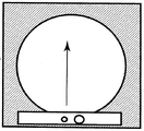
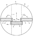
溶融はんだを利用したはんだバンプ形成装置や接着剤の塗布装置などの流体吐出装置では、一般的に、図1で示されるように、吐出ヘッドのサイズは、シリコンウエハやプリント基板等のワークと同じサイズであり、吐出ヘッドは、一定の方向に移動する。これにより、少ない走査回数で、スキージを動かすことによるマスクの撓みを防止、することができる。 In a fluid ejection device such as a solder bump forming device using molten solder or an adhesive application device, the size of the ejection head is generally the same as that of a workpiece such as a silicon wafer or a printed board as shown in FIG. The ejection head moves in a certain direction. Accordingly, it is possible to prevent the mask from being bent by moving the squeegee with a small number of scans.
しかし、シリコンウエハやプリント基板等が小型の場合ではこれでも問題がないが、300mmのシリコンウエハ等の大きなサイズのワークに使用する場合、それに対応して吐出ヘッドの長さを長くする必要がある。吐出ヘッドを長くすると、吐出ヘッドからワークに加わる圧力が必ずしも均等に分散せず、バラ付いてしまう。このため、ストロークにより発生する撓みによって、マスクが変形してしまい、吐出ヘッドから同じ量の流体を吐出できなかった。また、小さいヘッドを用いて複数回で流体を吐出すると、微細な吐出パターンでは隣接する吐出箇所が近いため、重複して吐出してしまい、吐出量が安定しなかった。 However, this is not a problem when the silicon wafer or printed circuit board is small, but when used for a large size workpiece such as a 300 mm silicon wafer, it is necessary to lengthen the discharge head correspondingly. . When the ejection head is lengthened, the pressure applied to the workpiece from the ejection head is not necessarily evenly distributed and varies. For this reason, the mask is deformed by the deflection generated by the stroke, and the same amount of fluid cannot be ejected from the ejection head. Further, when a fluid is ejected a plurality of times using a small head, since the adjacent ejection locations are close in a fine ejection pattern, they are ejected redundantly, and the ejection amount is not stable.
このようなことから、300mmのシリコンウエハ等の大きなサイズのワークに対して流体を吐出する場合であっても、安定した吐出量で流体を塗布できる流体塗布装置を提供することが求められる。また、ワークの極力広い領域に対して流体を塗布できることが望ましい。 For this reason, there is a need to provide a fluid application apparatus that can apply a fluid with a stable discharge amount even when a fluid is discharged onto a large-sized workpiece such as a 300 mm silicon wafer. In addition, it is desirable that the fluid can be applied to a region as wide as possible.
本発明は、上述の問題の少なくとも一部を解決するためになされたものであり、例えば、以下の形態として実現可能である。 SUMMARY An advantage of some aspects of the invention is to solve at least a part of the problems described above, and the invention can be implemented as, for example, the following forms.
本発明の第1の形態によれば、電子部品のワーク上のマスク中に流体を塗布するための流体吐出方法が提供される。この方法では、流体を収容可能なタンクと吐出ヘッドからなる、ワークの長さより短い幅のヘッド部を有し、前記吐出ヘッドには、ワーク上のマスクの内容物を吸引するための吸引口とその近傍には流体を吐出するための吐出ノズルが形成されており、かつ吸引口は、吐出ヘッドの進行方向の前方に設置されている流体吐出装置を用い、ワークに対して吐出ヘッドを往復することで吐出を行う。 According to the first aspect of the present invention, there is provided a fluid ejection method for applying a fluid into a mask on a workpiece of an electronic component. In this method, a head having a width shorter than the length of the work, which is composed of a tank capable of storing a fluid and a discharge head, has a suction port for sucking the contents of the mask on the work. A discharge nozzle for discharging fluid is formed in the vicinity thereof, and the suction port uses a fluid discharge device installed in front of the moving direction of the discharge head to reciprocate the discharge head with respect to the workpiece. To discharge.
第1の形態によれば、図2のように吐出ヘッドをワークに対して往復させることで、マスクの変形を低減することが可能となる。具体的には、吐出ヘッドが第1の方向に移動するときに発生していたマスクの変形が、第1の方向と逆方向である第2の方向に再度移動させることにより、一度変形したマスクが元に戻るため、マスクの変形を低減することが可能となる。 According to the first embodiment, it is possible to reduce the deformation of the mask by reciprocating the ejection head with respect to the workpiece as shown in FIG. Specifically, the mask deformed once when the deformation of the mask that has occurred when the ejection head moves in the first direction is moved again in the second direction that is opposite to the first direction. Therefore, the deformation of the mask can be reduced.
本発明の第2の形態によれば、電子部品のワーク上のマスク中に流体を塗布するための流体吐出装置が提供される。この流体吐出装置は、流体を収容可能なタンクと吐出ヘッドからなる、ワークの長さより短い幅のヘッド部であって、前記吐出ヘッドには、流体を吐出するための吐出ノズルの近傍に、ワーク上のマスクの内容物を吸引するためのスリット状の開口部を有する吸引口が、吐出ノズルを挟んで吸引口を両側に配置している。 According to the 2nd form of this invention, the fluid discharge apparatus for apply | coating a fluid in the mask on the workpiece | work of an electronic component is provided. This fluid discharge device is a head portion having a width shorter than the length of a work, which is composed of a tank capable of storing a fluid and a discharge head. The discharge head has a work piece in the vicinity of a discharge nozzle for discharging a fluid. A suction port having a slit-like opening for sucking the contents of the upper mask is arranged on both sides of the discharge nozzle.
第2の形態によれば、往復吐出を行うことでマスクの変形が一方向に偏らず、マスクの変形が低減されるので、吐出量がバラ付いてしまうこともなく、安定した吐出量の流体を吐出することが可能である。したがって、従来のワーク中の微細なマスク中への流体塗布で発生していた膨大な修正は無くなり、生産性が飛躍的に向上する。 According to the second embodiment, by performing reciprocating discharge, the deformation of the mask is not biased in one direction and the deformation of the mask is reduced, so that the discharge amount does not vary, and the fluid with a stable discharge amount is obtained. Can be discharged. Therefore, the enormous correction that has occurred by applying fluid to a fine mask in a conventional workpiece is eliminated, and the productivity is dramatically improved.
本発明の第3の形態によれば、電子部品のワーク上のマスク中に流体を塗布するための流体吐出装置が提供される。この流体吐出装置は、流体を収容可能なタンクと吐出ヘッドからなる、ワークより小さな複数のヘッド部を有し、前記ヘッド部はお互いに同期してワーク上の水平方向に移動し、前記吐出ヘッドには、ワーク上のマスクの内容物を吸引するための吸引口とその近傍には流体を吐出するための吐出ノズルが形成されており、かつ吸引口は、吐出ヘッドの進行方向の前方に設置されており、流体吐出前のワーク上のマスク中の空気を脱気、減圧することで、安定した同じ量の流体を吐出することができる。 According to the 3rd form of this invention, the fluid discharge apparatus for apply | coating a fluid in the mask on the workpiece | work of an electronic component is provided. The fluid ejection device includes a plurality of head portions smaller than a work, each of which includes a tank capable of storing a fluid and a discharge head, and the head portions move in a horizontal direction on the work in synchronization with each other. Has a suction port for sucking the contents of the mask on the workpiece and a discharge nozzle for discharging fluid in the vicinity thereof, and the suction port is set in front of the direction of travel of the discharge head The same amount of fluid can be discharged stably by degassing and depressurizing the air in the mask on the work before discharging the fluid.
本発明の第4の形態によれば、電子部品のワーク上のマスク中に流体を塗布するための流体吐出方法が提供される。この流体吐出方法は、流体を収容可能なタンクと吐出ヘッドからなる、ワークより小さく、角度が可変可能な複数のヘッド部を有し、前記ヘッド部はお互いに同期してワーク上の水平方向に移動し、前記吐出ヘッドには、ワーク上のマスクの内容物を吸引するための吸引口とその近傍には流体を吐出するための吐出ノズルが形成されており、かつ吸引口は、吐出ヘッドの進行方向の前方に設置されており、流体吐出前のワーク上のマスク中の空気を脱気、減圧することで、安定した同じ量の流体を吐出する。 According to the 4th form of this invention, the fluid discharge method for apply | coating the fluid in the mask on the workpiece | work of an electronic component is provided. This fluid discharge method has a plurality of head portions that are smaller than the workpiece and can be varied in angle, and are composed of a tank capable of containing fluid and a discharge head, and the head portions are synchronized with each other in the horizontal direction on the workpiece. The discharge head is formed with a suction port for sucking the contents of the mask on the workpiece and a discharge nozzle for discharging a fluid in the vicinity of the suction port. It is installed in the front of the traveling direction, and the air in the mask on the work before discharging the fluid is deaerated and decompressed to discharge the same amount of fluid in a stable manner.
複数の分割されたヘッド部は、ヘッド部に加えられた垂直方向からの圧力が均等に加えられるサイズであれば良い。具体的には、ワークの左右の長さの1/2〜1/4が好ましい。また、本願に用いられる複数のヘッド部の数は、ワークのサイズに応じて決定することが可能であるが、扱い易いのは2〜4個が適当である。ワークがシリコンウエハのように円形のものに吐出する場合は、3個のヘッド部を用いるのが最適である。図6のように、円形のワークへの吐出では、ヘッド部は前後に水平に移動させるだけでなく、左右に配置されたヘッド部を円周に沿って角度を変えることで、角形に比べて吐出が難しい円形のワークでも、均一な吐出量を得ることができる。 The plurality of divided head portions may have any size as long as pressure from the vertical direction applied to the head portion is evenly applied. Specifically, 1/2 to 1/4 of the left and right length of the workpiece is preferable. In addition, the number of the plurality of head portions used in the present application can be determined according to the size of the work, but 2 to 4 are suitable for easy handling. When the work is discharged onto a circular object such as a silicon wafer, it is optimal to use three head portions. As shown in FIG. 6, in discharging to a circular workpiece, the head portion is not only moved horizontally in the front-rear direction, but also by changing the angle of the head portions arranged on the left and right along the circumference, compared to a square shape. Even for circular workpieces that are difficult to discharge, a uniform discharge amount can be obtained.
第4の形態によれば、ヘッド部がワークよりも長さが短いために、吐出ヘッドからワークに加わる圧力が必ずしも均等に分散せず、吐出量がバラ付いてしまうこともなく、均一の圧力がワークに加えることが可能である。また、ヘッド部はお互いに同期してワーク上の水平方向を移動するため、吐出漏れもなく、安定した吐出量の流体を吐出することが可能である。したがって、従来のワーク中の微細なマスク中への流体塗布で発生していた膨大な修正は無くなり、生産性が飛躍的に向上する。 According to the fourth embodiment, since the head portion is shorter than the work, the pressure applied from the discharge head to the work is not necessarily evenly distributed, and the discharge amount does not vary. Can be added to the workpiece. In addition, since the head parts move in the horizontal direction on the workpiece in synchronization with each other, there is no discharge leakage and it is possible to discharge a stable discharge amount of fluid. Therefore, the enormous correction that has occurred by applying fluid to a fine mask in a conventional workpiece is eliminated, and the productivity is dramatically improved.
本発明の第5の形態によれば、電子部品のワーク上に流体を塗布するための流体吐出装置が提供される。この流体吐出装置は、ワークを支持するための第1のステージと、ワークの上方を水平方向に直線的に移動しながら流体を吐出するように構成された第1の吐出ヘッドであって、第1のステージの外部の初期位置から、第1のステージの上方を経由して、第1のステージの外部の最終位置まで移動するように構成された第1の吐出ヘッドと、配置角度を変えつつ第1のステージの上方を水平方向に移動しながら流体を吐出するように構成された第2の吐出ヘッドと、第1の吐出ヘッドの移動経路上において、初期位置から第1のステージの外縁まで、および、第1のステージの外縁から最終位置まで配置された第2のステージであって、吐出ヘッドが第2のステージ上を摺動可能に配置された第2のステージと、を備えている。第1の吐出ヘッドおよび第2の吐出ヘッドにおける流体を吐出可能な範囲は、第1のステージ上のワークを配置する領域の幅よりも小さい。 According to the 5th form of this invention, the fluid discharge apparatus for apply | coating a fluid on the workpiece | work of an electronic component is provided. This fluid ejection device is a first stage for supporting a workpiece, and a first ejection head configured to eject fluid while linearly moving in the horizontal direction above the workpiece, The first discharge head configured to move from the initial position outside the first stage to the final position outside the first stage via the top of the first stage, while changing the arrangement angle From the initial position to the outer edge of the first stage on the second discharge head configured to discharge the fluid while moving in the horizontal direction above the first stage, and on the movement path of the first discharge head And a second stage arranged from the outer edge of the first stage to the final position, wherein the ejection head is slidably arranged on the second stage. . The range in which the fluid can be ejected in the first ejection head and the second ejection head is smaller than the width of the region where the work is disposed on the first stage.
かかる流体吐出装置によれば、ワークのサイズより小さな複数の吐出ヘッドを用いて流体を吐出するので、大型のワークを処理する場合であっても、吐出ヘッドからワークに加わる圧力がほぼ均等に分散する。したがって、吐出ヘッドの吐出量が安定する。また、第1のステージの外部において、第1の吐出ヘッドの移動経路上に第2の移動ステージが配置されているので、第1の吐出ヘッドは、ワークの外縁から外縁まで塗布を行うことができる。さらに、第2の吐出ヘッドは、配置角度を変えながら移動するので、ワーク上の位置から塗布を開始した場合であっても、広範囲に流体を吐出できる。 According to such a fluid ejection device, the fluid is ejected using a plurality of ejection heads smaller than the size of the workpiece, so that even when processing a large workpiece, the pressure applied to the workpiece from the ejection head is almost evenly distributed. To do. Therefore, the discharge amount of the discharge head is stabilized. Further, since the second moving stage is arranged on the moving path of the first discharge head outside the first stage, the first discharge head can apply from the outer edge to the outer edge of the workpiece. it can. Furthermore, since the second ejection head moves while changing the arrangement angle, the fluid can be ejected over a wide range even when application is started from a position on the workpiece.
本発明の第6の形態によれば、第5の形態において、第2の吐出ヘッドは、2つの吐出ヘッドを備えている。2つの吐出ヘッドは、第1の吐出ヘッドの両側に1つずつ配置されている。かかる形態によれば、円形のワークのほぼ全領域に対して流体を効率的に塗布することができる。 According to the sixth aspect of the present invention, in the fifth aspect, the second ejection head includes two ejection heads. The two ejection heads are arranged one on each side of the first ejection head. According to this form, the fluid can be efficiently applied to almost the entire area of the circular workpiece.
本発明の第7の形態によれば、第5または第6の形態において、第1の吐出ヘッドおよび第2の吐出ヘッドは、同期して同時に移動するように構成される。かかる形態によれば、処理時間を短縮化することができる。 According to the seventh aspect of the present invention, in the fifth or sixth aspect, the first ejection head and the second ejection head are configured to move simultaneously in synchronization. According to this form, the processing time can be shortened.
本発明の第8の形態によれば、第5ないし第7のいずれかの形態において、第1の吐出ヘッドおよび第2の吐出ヘッドは、互いに協働して、ワーク上の被吐出領域を実質的に重複することなくカバーするように構成される。かかる形態によれば、効率的に流体を塗布することができる。また、同一箇所に複数回にわたって流体が塗布されることがないので、塗布量のバラツキを抑制することができる。 According to an eighth aspect of the present invention, in any one of the fifth to seventh aspects, the first ejection head and the second ejection head cooperate with each other to substantially define the area to be ejected on the workpiece. It is configured to cover without overlapping. According to this form, the fluid can be efficiently applied. Moreover, since the fluid is not applied multiple times to the same location, variations in the coating amount can be suppressed.
本発明の第9の形態によれば、第5ないし第8のいずれかの形態において、第1の吐出ヘッドおよび第2の吐出ヘッドにおける流体を吐出可能な範囲は、第1のステージ上のワークを配置する領域の幅の1/4以上、1/2以下である。かかる形態によれば、装置構成を過剰に複雑化することなく、第5の形態の効果を得ることができる。 According to the ninth aspect of the present invention, in any of the fifth to eighth aspects, the range in which the fluid can be ejected from the first ejection head and the second ejection head is the workpiece on the first stage. Is not less than 1/4 and not more than 1/2 of the width of the region in which the According to this aspect, the effect of the fifth aspect can be obtained without excessively complicating the apparatus configuration.
A.第1実施形態:
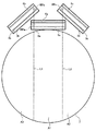
まず、流体塗布装置のヘッド部1の構成を説明する。図3が本発明によるヘッド部1の詳細を示す図である。ヘッド部1は、溶融はんだ等を収容可能な流体タンク2と、下端に設けた吐出ヘッド3と、を備える。溶融はんだなど温度コントロールが必要な流体に用いるときは、流体タンク2の腹部にヒータ4を巻き付けるなど、加熱手段を取り付けることもできる。吐出ヘッド3には、ヘッド下端に設けた流体吐出ノズル5と吸引口6とを有し、吸引口6は流体吐出ノズル5よりも進行方向に向かって先に吸引工程が実施できるように取り付けられている。流体吐出ノズル5及び吸引口6にも温度コントロールが必要な流体に用いるときは、吐出ヘッド3下端にもヒータ4を取り付けることが可能となる。A. First embodiment:
First, the configuration of the
吐出ヘッド3のノズル開口の形状としては、丸状、スリット状およびその他の公知のものを採用することができる。特に、ノズル開口の形状としてスリット状を用いると、複数のワーク7上の吐出対象に同時に流体を吐出することが可能となる。また、吐出ヘッド3に取り付けられた吸引口6の形状も丸状、スリット状およびその他の公知のものを採用することができるが、開口の形状としてスリット状を用いることで、シリコンウエハやプリント基板等のワーク7に対して複数の箇所を同時にマスク8内の空気や既に吐出した流体を除去することが可能となる。さらに、本願では図4のように、吸引口6を吐出ヘッド3の前後に取り付けることで、マスクの変形を均一化することが可能となり、安定した往復での吐出が可能となる。 As the shape of the nozzle opening of the discharge head 3, a round shape, a slit shape, and other known shapes can be adopted. In particular, when a slit shape is used as the shape of the nozzle opening, it becomes possible to simultaneously discharge fluid to the discharge targets on the plurality of
次に、全体の構成を説明する。図3に示すように本発明の流体塗布装置は、全体として流体を塗布させるべき電子部品のワーク7に対して接近および離反するように上下方向(Y)に移動可能であるとともに、水平方向(X)にも移動可能である。ワーク7の上部には、ポリイミドやレジストによって形成されたマスク8が置かれている。吐出ヘッド3は、流体吐出時には、流体吐出ノズル5がワーク7に接触する位置まで下降する。流体吐出ノズル5とワーク7との接触状態が維持されたまま液体吐出ヘッド3は水平に移動する。吐出ヘッド3が水平に移動すると、まず進行方向に向かって先に吸引工程が実施できるように取り付けられた吸引口6より、ワーク7上に設置されたマスク8内の空気を吸引させる。複数回目の吐出で、マスク8内に吐出した流体もこの段階で吸引することが可能となる。加熱手段が必要な流体は、吐出ヘッド3下部に設置されたヒータ4で加熱されることで、吸引可能となる。その後、液体吐出ヘッド3が水平移動すると、流体吐出ノズル5の開口から流体が吐出され、ワーク7上のマスク8中には流体が塗布される。流体の塗布が終了すると、液体吐出ヘッド3はワーク7から離れるように持ち上げられる。マスク8を使用しない場合でも、同じ工程が可能である。 Next, the overall configuration will be described. As shown in FIG. 3, the fluid application apparatus of the present invention is movable in the vertical direction (Y) so as to approach and separate from the
流体吐出装置1は、タンク2内の流体を所望の温度に保つためのヒータ4を備える。ヒータ4は、タンク2の壁部に内蔵されたものとすることができる。ヒータ4は、タンク2内の溶融はんだ等の流体9の塗布条件に最適な粘度を保つのに適切な温度に加熱されるよう、管理制御されている。 The
図示はしないが、流体吐出装置1は、タンク2から延長管路10を通して、流体連通可能な圧力供給手段11とつながっており、吸引口6から続く吸引管延長管路12を通して、流体連通可能な減圧供給手段13とつながっている。圧力供給手段11は、例えば0.06ないし0.1MPa(これに限定されない)の圧力の窒素ガスを発生させる圧力発生源14を有している。圧力発生源14は、ゲート弁15および3方弁16を介してタンク2内へ圧力を供給する。タンク2内に保持されていた溶融はんだは、圧力発生源14からの圧力を受けて流体吐出ノズル5の開口から射出される。 Although not shown, the
減圧供給手段13は、減圧発生装置であるマイクロエジェクタ16を有している。減圧発生装置16は、例えばレギュレータ17および絞り弁18を介して、0.4MPa(これに限定されない)の圧力の窒素ガスを発生させる圧力発生源19と連結され、吸引管延長管路12を介して吸引口6へ負圧を供給する。 The reduced pressure supply means 13 has a
流体吐出装置は、圧力センサ20と制御装置21とを有する。圧力センサ20は、タンク2内と流体連通する延長管路17に設けられた3方弁18に連結し、タンク2内の圧力を監視する。タンク2内の圧力を示す信号は、圧力センサ20から制御装置21に送られる。制御装置21は、作業工程の進捗に合わせて圧力発生源14、減圧発生装置16,レギュレータ17,圧力発生源19および各弁を操作し、タンク2内に圧力を供給する。供給すべき適切な圧力値は、圧力センサ20からの信号に基づいて決定される。タンク2内の溶融はんだを流体吐出ノズル5の開口から射出する場合、タンク2内と圧力センサ20とが流体連通するように操作される。タンク2内に供給される正圧の大きさは、例えば圧力発生源14にて発生される圧力値を制御装置21によって調整することによって変化させることができる。あるいは、圧力供給手段11に設けた調整弁(図示せず)を制御装置21が調整することによって圧力値を変化させてもよい。 The fluid ejection device includes a pressure sensor 20 and a control device 21. The pressure sensor 20 is connected to a three-
溶融はんだ等の流体を流体吐出ノズル5の開口から射出させたりタンク2内に保持したりするためにタンク2内に供給されるべき適切な圧力値は、タンク2内に収容されている溶融はんだの量(重量)によっても左右される。したがって、制御装置21は、タンク2内の流体量に関するデータを入力されるようにしてもよい。この場合、制御装置21は、タンク2内の流体量のデータから、流体の射出またはタンク内保持のために適切なタンク内圧力値を計算することができる。さらに、制御装置21は、該適切なタンク内圧力値と圧力センサ20からの信号が示す実際のタンク内圧力値とを比較し、適切なタンク内圧力が得られるよう、圧力発生源14および各弁を調整することができる。 An appropriate pressure value to be supplied into the tank 2 in order to inject a fluid such as molten solder from the opening of the fluid discharge nozzle 5 or hold it in the tank 2 is the molten solder contained in the tank 2. It depends on the amount (weight). Therefore, the control device 21 may receive data related to the amount of fluid in the tank 2. In this case, the control device 21 can calculate a pressure value in the tank appropriate for the injection of the fluid or the retention in the tank from the data of the fluid amount in the tank 2. Further, the control device 21 compares the appropriate tank internal pressure value with the actual tank internal pressure value indicated by the signal from the pressure sensor 20 so that the appropriate tank internal pressure can be obtained. The valve can be adjusted.
また、タンク2内の流体量の変動による、上記適切なタンク内圧力値の変動をできるだけ少なくするため、流体供給装置22をタンク2に連結させて設けてもよい。流体供給装置22は、流体吐出装置の稼働中にタンク2内の溶融はんだが消費されたとき、タンク2内の流体量が常にほぼ一定となるように追加の流体を自動供給することができる。タンク2内の流体の量を知るためには、公知のいかなる手法を利用することも可能である。処理した製品数などから、タンク2内の溶融はんだの量を推測することができ、該タンク内の流体量に対応する上記適切なタンク内圧力値を経験により知ることができる場合には、制御装置21は圧力センサ20からの信号のみに基づいてタンク2内に供給されるべき圧力を制御することができる。 Further, the
最後に、第1実施形態の流体吐出装置の動作を説明する。第1実施形態の吐出ヘッド3は、ワーク7から離れた定位置に固定されているが、流体吐出時には、吐出ヘッド3が上下方向、水平方向にも移動して、吐出ヘッド3はワーク7上のマスク8の吐出部分に接触する位置まで下降する。圧力発生源14から供給された圧力は、ゲート弁15を介してタンク2内へ圧力を供給する。タンク2内に保持されていた流体9は、圧力発生源14からの圧力を受けて吐出ノズル5の開口から射出される。必ず流体9を吐出中の吐出ヘッド3が、吸引ノズル5が設置されている方から先に水平に移動し、ワーク7上のマスク8の開口部の空気を減圧してから、吐出ノズル5で流体を吐出するように、吐出ヘッド3は移動する。一方向へのワーク7上のマスク8の開口部への流体の吐出が終了すると、今度は折り返しの吐出ヘッド3の移動を行い、吐出ヘッド3は往復の移動が完了する。かかる動作によれば、吐出ヘッド3がワーク7に対して往復動作を行いつつ、流体を吐出することにより、マスクの変形が一方向に偏らず、マスクの変形が低減される。 Finally, the operation of the fluid ejection device of the first embodiment will be described. Although the discharge head 3 of the first embodiment is fixed at a fixed position away from the
B.第2実施形態:
以下、本発明の第2実施形態について、第1実施形態と異なる点を中心に説明する。第2の実施形態の構成のうち、特に断らない点については、第1実施形態と同じである。B. Second embodiment:
Hereinafter, the second embodiment of the present invention will be described focusing on differences from the first embodiment. Of the configuration of the second embodiment, the points not particularly noted are the same as those of the first embodiment.
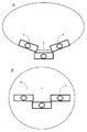
第2実施形態の流体吐出装置の動作を説明する。第2実施形態のヘッド部1は、ワーク7から離れた定位置に固定されているが、流体吐出時には、ヘッド部1が上下方向、水平方向にも移動して、吐出ヘッド3はワーク7上のマスク8の吐出部分に接触する位置まで下降する。図7Aは、シリコンウエハに流体を吐出するときの複数のヘッド部1が下降した状態を示す一例である。3個のヘッド部1を有しており、中央のヘッド部は進行方向に対して平行であり、左右のヘッド部は、円形のワークに沿って配置されており、進行方向に対して非平行である。初期ポジションから下降した状態では、左のヘッド部が時計回りに10〜60度回転しており、中央のヘッド部がワークに対して平行、右のヘッド部が反時計回りに10〜60度回転した状態で保持されている。左右のヘッド部のワークの中央側の先端は、中央に配置されたヘッド部1より進行方向に向かって、前方に配置されており、ヘッドが進行報告に向かって水平移動するときに、左のヘッド部は、反時計回りに旋回し、右のヘッド部は、時計回りに旋回して、進行方向に対して平行に近づいている。 The operation of the fluid ejection device of the second embodiment will be described. The
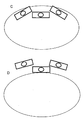
図7Bは、3個のヘッド部1がシリコンウエハの中央部付近の状態を示した一例である。中央および左右のヘッド部1は、全て進行方向に向かって平行となっている。シリコンウエハの中央部を過ぎて3個のヘッド部1が移動すると、左のヘッド部は反時計回りに旋回し、右のヘッド部は時計回りに旋回する。そして最終ポジションに到達した状態を示すのが図8Cである。最終ポジションでは、左のヘッド部が反時計回りに10〜60度回転しており、中央のヘッド部がワークに対して平行、右のヘッド部が時計回りに10〜60度回転した状態で保持されている。この状態では、初期ポジションとは対称的に、中央のヘッド部1は進行方向に対して平行であり、左右のヘッド部は、円形のワークに沿って配置されており、進行方向に対して非平行である。左右のヘッド部のワークの中央側の先端は、中央に配置されたヘッド部より進行方向に向かって、前方に配置されている。さらに、図8Dはマスクを取り外すために3個のヘッド部が、シリコンウエハの外側に移動している状態を示している。このポジションでは、図8Cと同様に中央のヘッド部は進行方向に対して平行であり、左右のヘッド部は、円形のワークに沿って配置されており、進行方向に対して非平行である。左右のヘッド部のワークの中央側の先端は、中央に配置されたヘッド部より進行方向に向かって、前方に配置されている。本願の流体吐出装置の左右のヘッド部は初期ポジションから最終ポジションへの移動で、10〜60度ワーク上で外周に向かって旋回することが可能となっている。 FIG. 7B shows an example in which three
本実施形態では、流体9を吐出中の吐出ヘッド3が、吸引ノズル5が設置されている方から先に水平に移動し、ワーク7上のマスク8の開口部の空気を減圧してから、吐出ノズル5で流体を吐出するように、吐出ヘッド3は移動する。圧力発生源14から供給された圧力は、ゲート弁15を介してタンク2内へ圧力を供給する。タンク2内に保持されていた流体9は、圧力発生源14からの圧力を受けて吐出ノズル5の開口から射出される。吐出ヘッド3は、ワーク7のマスク8の上をなぞって、水平に移動して、決められた範囲の流体の塗布を完了する。かかる動作によれば、ワーク7のサイズよりも小さな複数の吐出ヘッド3を用いて流体の吐出を行うことにより、吐出量のバラツキを抑制し、吐出量を安定化させることができる。 In the present embodiment, the ejection head 3 that is ejecting the fluid 9 moves horizontally first from the side where the suction nozzle 5 is installed, and depressurizes the air in the opening of the mask 8 on the
図9〜11は、吐出ヘッド3a〜3cの移動経路の具体例を示している。図9は、吐出ヘッド3a〜3cの走査前の初期位置を示している。第1の吐出ヘッド3aは、ワーク7の外部に配置されている。第1の吐出ヘッド3aの長手方向は、第1の吐出ヘッド3aの進行方向(紙面の上方に向かう方向)に対して垂直である。第2の吐出ヘッド3b,3cは、円形のワーク7の内周に接するように配置されている。換言すれば、第2の吐出ヘッド3b,3cは、第1の吐出ヘッド3aよりも進行方向の前方に配置されている。第2の吐出ヘッド3b,3cの長手方向は、吐出ヘッド3a〜3cの進行方向(紙面の上方に向かう方向)に対して傾いている。この傾きは、例えば、進行方向に対して10〜60度の角度であってもよい。第2の吐出ヘッド3bは、進行方向に進むに従って、反時計回りに旋回し、第2の吐出ヘッド3cは、進行方向に進むに従って、時計回りに旋回する。第2の吐出ヘッド3b,3cのこの旋回しながら進行方向に進む動作は、例えば、ロボットアームによって実現できる。 9 to 11 show specific examples of movement paths of the ejection heads 3a to 3c. FIG. 9 shows an initial position of the ejection heads 3a to 3c before scanning. The
図10は、吐出ヘッド3a〜3cの走査中の中間位置を示している。第1の吐出ヘッド3aは、図9に示した初期位置から、ワーク7の中央まで直線的に移動している。第1の吐出ヘッド3aの基準点RPaは、直線L1に沿って移動する。第2の吐出ヘッド3b,3cは、図9に示した初期位置から、旋回しながら進行方向に進むことによって、第1の吐出ヘッド3aと同じ配置角度で配置されている。つまり、第1の吐出ヘッド3aの長手方向は、第2の吐出ヘッド3b,3cの長手方向と平行である。この旋回移動において、第2の吐出ヘッド3b,3cの基準点RPb,RPcは、それぞれ、直線L1,L2に沿って移動する。なお、基準点RPb,RPcは、吐出ノズル5の第1の吐出ヘッド3a側の端部に設定されている。 FIG. 10 shows an intermediate position during scanning of the ejection heads 3a to 3c. The
図11は、吐出ヘッド3a〜3cの走査終了後の最終位置を示している。第1の吐出ヘッド3aは、図10に示した中間位置から、ワーク7の外部(初期位置とは反対側の外部)の位置まで移動している。第2の吐出ヘッド3b,3cは、図10に示した中間位置から、旋回しながら進行方向に進むことによって、吐出ヘッド3a〜3cの進行方向(紙面の上方に向かう方向)に対して傾いている。この傾きは、初期位置における傾きと逆の傾きである。この傾きは、例えば、進行方向に対して10〜60度の角度であってもよい。 FIG. 11 shows the final position after the scanning of the ejection heads 3a to 3c. The
このように吐出ヘッド3a〜3cが移動することによって、ワーク7のほぼ全領域に対して流体9を塗布することができる。具体的には、第1の吐出ヘッド3aによって中央の領域A1における塗布がカバーされ、左側の第2の吐出ヘッド3bによって左側の領域A2における塗布がカバーされ、右側の第2の吐出ヘッド3cによって右側の領域A3におけるが塗布がカバーされる。吐出ヘッド3a〜3cの吐出ノズル5a〜5cの形成領域と、基準位置RP1〜RP3と、を調節することによって、ワーク7上の被吐出領域を実質的に重複することなくカバーすることも可能である。 Thus, the fluid 9 can be applied to almost the entire region of the
C.第3実施形態:
以下、本発明の第3実施形態について説明する。図3は、第3実施形態による流体塗布装置の一例としてのはんだバンプ形成装置の概略構成を示す模式図である。はんだバンプ形成装置は、電子部品のワーク7(例えば、シリコンウエハやプリント基板等)上に流体9(ここでは、溶融はんだ)を塗布して、はんだバンプを形成する装置である。図3に示すように、はんだバンプ形成装置は、吐出ヘッド部1と、圧力供給手段11と、圧力発生源14と、マイクロエジェクタ16と、圧力発生源19と、流体供給装置22と、を備えている。また、はんだバンプ形成装置は、ステージ30〜32を備えている(図12参照)。これらの詳細については後述する。C. Third embodiment:
Hereinafter, a third embodiment of the present invention will be described. FIG. 3 is a schematic diagram showing a schematic configuration of a solder bump forming apparatus as an example of a fluid applying apparatus according to the third embodiment. The solder bump forming apparatus is an apparatus that forms a solder bump by applying a fluid 9 (molten solder in this case) onto a workpiece 7 (for example, a silicon wafer or a printed board) of an electronic component. As shown in FIG. 3, the solder bump forming apparatus includes an
図5は、はんだバンプ形成装置の吐出ヘッド部1を示す概略図である。図5に示すように、吐出ヘッド部1は、流体9を収容可能な流体タンク2と、その下端に設けられた吐出ヘッド3と、を備えている。この吐出ヘッド部1は、任意のアクチュエータ(図示省略)によって、ワーク7の上方を水平方向に移動可能に構成されている。本実施例では、吐出ヘッド部1は、ワーク7上に配置されたマスク8上を摺動的に移動する。マスク8は、はんだバンプを形成すべき箇所に形成された複数の孔部を有している。これらの孔部は、マスク8を、その厚み方向(鉛直方向)に貫通している。マスク8は、例えば、ポリイミドやレジストによって形成されてもよい。さらに、吐出ヘッド部1は、鉛直方向に、すなわち、ワーク7に対して接近および離反するように移動可能に構成されている。 FIG. 5 is a schematic view showing the
流体タンク2は、図3に示すように、流体供給装置22に接続されていてもよい。流体供給装置22は、流体タンク2内の流体9が消費されたときに、流体タンク2内に収容された流体量が常にほぼ一定となるように、流体9を自動補給することができる。かかる構成によれば、流体タンク2内に収容された流体量の変動によるタンク内の圧力の変動を抑制できる。 The fluid tank 2 may be connected to a
本実施例では、吐出ヘッド部1は、タンク2内の流体9を所望の温度に保つためのヒータ4を備えている。ヒータ4は、タンク2の壁部に内蔵されていてもよい。ヒータ4は、タンク2内の流体9の塗布条件に最適な粘度を保つのに適切な温度に流体9を加熱するように制御される。 In this embodiment, the
図5に示すように、吐出ヘッド3は、吐出ノズル5と、吸引口6と、を有している。吐出ノズル5は、吐出ヘッド3を鉛直方向に貫通し、流体タンク2に連通している。図3に示すように、流体タンク2は、延長管路10を介して、圧力供給手段11に接続されている。圧力供給手段11は、例えば0.06ないし0.1MPa(これに限定されない)の圧力の窒素ガスを発生させる圧力発生源14を備えている。圧力発生源14は、ゲート弁および三方弁を介して吐出ヘッド部1へ圧力を供給する。この圧力によって、流体タンク2内の流体9が吐出ノズル5から吐出される。 As shown in FIG. 5, the discharge head 3 has a discharge nozzle 5 and a suction port 6. The discharge nozzle 5 penetrates the discharge head 3 in the vertical direction and communicates with the fluid tank 2. As shown in FIG. 3, the fluid tank 2 is connected to the pressure supply means 11 via the
図5に示すように、吸引口6は、吐出ヘッド3を鉛直方向に貫通し、吸引管延長管路12に連通している。図3に示すように、吸引管延長管路12は、減圧供給手段13に接続されている。減圧供給手段13は、減圧発生装置であるマイクロエジェクタ16を備えている。マイクロエジェクタ16は、例えばレギュレータおよび絞り弁18を介して、0.4MPa(これに限定されない)の圧力の窒素ガスを発生させる圧力発生源19に接続されている。この減圧供給手段13によって、吸引管延長管路12を介して吸引口6へ負圧が供給される。 As shown in FIG. 5, the suction port 6 penetrates the ejection head 3 in the vertical direction and communicates with the suction
この吸引口6は、吐出ヘッド部1の進行方向において、吐出ノズル5よりも前方に配置されている。このため、吐出ノズル5から流体を吐出する前に、マスク8の孔部内を吸引口6から脱気・減圧することができる。これにより、安定して同じ量の流体を吐出することができる。 The suction port 6 is disposed in front of the discharge nozzle 5 in the traveling direction of the
吐出ノズル5の開口形状としては、丸状、スリット状およびその他の公知の形状を採用することができる。特に、吐出ノズル5の開口形状としてスリット状を採用すると、マスク8の複数の孔部内に同時に流体を吐出することが可能となる。また、吸引口6の開口形状も、丸状、スリット状およびその他の公知の形状を採用することができる。吸引口6の開口形状としてスリット状を採用した場合、複数の箇所において同時に空気や既に吐出した流体を吸引することが可能となる。 As the opening shape of the discharge nozzle 5, a round shape, a slit shape, and other known shapes can be adopted. In particular, when a slit shape is employed as the opening shape of the discharge nozzle 5, it becomes possible to simultaneously discharge fluid into the plurality of holes of the mask 8. In addition, the opening shape of the suction port 6 may be a round shape, a slit shape, or other known shapes. When a slit shape is employed as the opening shape of the suction port 6, air or fluid that has already been discharged can be sucked simultaneously at a plurality of locations.
上述したはんだバンプ形成装置の動作の概略について以下に説明する。吐出ヘッド部1は、流体吐出時には、吐出ヘッド3(すなわち、吐出ノズル5の下端に位置する開口部)がマスク8に接触する位置まで下降する。そして、吐出ヘッド3は、吐出ノズル5とマスク8との接触状態が維持された状態で、水平方向に移動する。吐出ヘッド3が水平に移動すると、まず、吐出ヘッド3の進行方向前方に配置された吸引口6から、ワーク7上に配置されたマスク8の孔部内の空気が吸引される。また、吐出ヘッド3が同一の孔部上を複数回走査する場合には、以前に孔部に吐出された流体9もこの段階で吸引される。吐出ヘッド3の下部には、ヒータが配置されてもよい。こうすれば、以前に孔部に吐出された流体9が固化することがないので、当該流体を確実に吸引することができる。その後、吐出ヘッド3をさらに水平移動すると、吸引口6によって吸引が実施された後のマスク8の孔部内に、吐出ノズル5の開口から流体9が吐出される。これによって、ワーク7上のマスク8の孔部内に流体9が塗布される。流体9の塗布が終了すると、吐出ヘッド3は、マスク8から離れるように持ち上げられる。マスク8を使用しない場合でも、同じ工程が可能である。 An outline of the operation of the above-described solder bump forming apparatus will be described below. The
図12は、吐出ヘッド部1および第1のステージステージ30および第2のステージ31,32の配置を示す上面図である。図12に示すように、本実施例のはんだバンプ形成装置は、3つの吐出ヘッド3a〜3cを備えている。実際には、吐出ヘッド部1も3つ設けられているが、図12では、それらの図示を省略している。また、マスク8についても図示を省略している。本実施例では、吐出ヘッド3a〜3cの移動形態の違いに着目して、吐出ヘッド3aを第1の吐出ヘッド3aとも呼び、吐出ヘッド3b,3cを第2の吐出ヘッド3b,3cとも呼ぶ。また、はんだバンプ形成装置は、ワーク7を支持するための第1のステージステージ30と、第1のステージステージ30の外部に配置された第2のステージ31,32と、を備えている。 FIG. 12 is a top view showing the arrangement of the
本実施例では、第1のステージステージ30は、円形のワーク7よりも若干大きな円形の形状を有している。ただし、第1のステージステージ30の形状は、ワーク7の形状に応じて、任意の形状を有していてもよい。第2のステージ31,32は、第1のステージステージ30の外縁と接触するように、第1のステージステージ30の径方向の両端に対向して配置されている。本実施例では、第2のステージ31,32は、矩形形状を有している。ただし、第2のステージ31,32は、第1のステージステージ30の外縁まで延在する任意の形状であってもよい。例えば、第2のステージ31,32は、第1のステージステージ30の外縁の円弧形状と一致する円弧を有する凹型形状を有していてもよい。 In the present embodiment, the
図13は、第1のステージステージ30および第2のステージ31,32の配置を示す断面図である。図13に示すように、第1のステージステージ30は、その中央にワーク7を配置するための凹部を有している。この凹部は、当該凹部内にワーク7およびマスク8が配置されたときに凹部の上端とマスク8の上端とが一致する大きさに形成されている。また、第2のステージ31および32の上端は、第1のステージステージ30の凹部の上端およびマスク8の上端と同一高さにある。これにより、後述する第1の吐出ヘッド3aは、ステージ30〜32の上面およびマスク8と接触しながら、水平方向に摺動的に移動することができる。 FIG. 13 is a cross-sectional view showing the arrangement of the
第1の吐出ヘッド3aは、ワーク7の上方を水平方向に移動するように構成されている。具体的には、第1の吐出ヘッド3aは、第1のステージステージ30の外部の初期位置(第2のステージ31上の位置)から第1のステージステージ30の外部の最終位置(第2のステージ32上の位置)まで、ワーク7の中央を通って直線的に移動する。 The
第2の吐出ヘッド3b,3cは、第1の吐出ヘッド3aの両側にそれぞれ配置されている。この第2の吐出ヘッド3b,3cは、配置角度を変えながら、第1の吐出ヘッド3aと同じ進行方向にワーク7の上方を移動する。 The second ejection heads 3b and 3c are respectively arranged on both sides of the
吐出ヘッド3a〜3cの長手方向の幅(換言すれば、吐出ヘッド3a〜3cにおける流体9を吐出可能な範囲)は、いずれも、ワーク7の幅(換言すれば、ワーク7を配置する領域)よりも小さい。このため、吐出ヘッド3a〜3cは、互いに協働して、ワーク7の全領域に流体9を塗布する。換言すれば、吐出ヘッド3a〜3cがそれぞれ異なる領域に流体9を塗布することによって、ワーク7の全領域に流体9が塗布される。吐出ヘッド3a〜3cの幅は、ワーク7を配置する領域の幅の1/4以上、1/2以下であってもよい。こうすれば、装置構成を過剰に複雑化することなく、流体9を均一に塗布することができる。 The width in the longitudinal direction of the discharge heads 3a to 3c (in other words, the range in which the fluid 9 can be discharged from the discharge heads 3a to 3c) is the width of the work 7 (in other words, the region in which the
図14〜16は、吐出ヘッド3a〜3cの移動経路の具体例を示している。図14は、吐出ヘッド3a〜3cの走査前の初期位置を示している。第1の吐出ヘッド3aは、第2のステージ31(図14では図示省略)上に配置されている。第1の吐出ヘッド3aの長手方向は、第1の吐出ヘッド3aの進行方向(紙面の上方に向かう方向)に対して垂直である。第2の吐出ヘッド3b,3cは、円形のワーク7の内周に接するように配置されている。換言すれば、第2の吐出ヘッド3b,3cは、第1の吐出ヘッド3aよりも進行方向の前方に配置されている。第2の吐出ヘッド3b,3cの長手方向は、吐出ヘッド3a〜3cの進行方向(紙面の上方に向かう方向)に対して傾いている。この傾きは、例えば、進行方向に対して10〜60度の角度であってもよい。第2の吐出ヘッド3bは、進行方向に進むに従って、反時計回りに旋回し、第2の吐出ヘッド3cは、進行方向に進むに従って、時計回りに旋回する。第2の吐出ヘッド3b,3cのこの旋回しながら進行方向に進む動作は、例えば、ロボットアームによって実現できる。 14 to 16 show specific examples of movement paths of the ejection heads 3a to 3c. FIG. 14 shows the initial position of the ejection heads 3a to 3c before scanning. The
図15は、吐出ヘッド3a〜3cの走査中の中間位置を示している。第1の吐出ヘッド3aは、図14に示した初期位置から、ワーク7の中央まで直線的に移動している。第1の吐出ヘッド3aの基準点RPaは、直線L1に沿って移動する。第2の吐出ヘッド3b,3cは、図14に示した初期位置から、旋回しながら進行方向に進むことによって、第1の吐出ヘッド3aと同じ配置角度で配置されている。つまり、第1の吐出ヘッド3aの長手方向は、第2の吐出ヘッド3b,3cの長手方向と平行である。この旋回移動において、第2の吐出ヘッド3b,3cの基準点RPb,RPcは、それぞれ、直線L1,L2に沿って移動する。なお、基準点RPb,RPcは、吐出ノズル5の第1の吐出ヘッド3a側の端部に設定されている。 FIG. 15 shows an intermediate position during scanning of the ejection heads 3a to 3c. The
図16は、吐出ヘッド3a〜3cの走査終了後の最終位置を示している。第1の吐出ヘッド3aは、図15に示した中間位置から、第2のステージ32(図16では図示省略)上の位置まで移動している。第2の吐出ヘッド3b,3cは、図15に示した中間位置から、旋回しながら進行方向に進むことによって、吐出ヘッド3a〜3cの進行方向(紙面の上方に向かう方向)に対して傾いている。この傾きは、初期位置における傾きと逆の傾きである。この傾きは、例えば、進行方向に対して10〜60度の角度であってもよい。 FIG. 16 shows the final position after the scanning of the ejection heads 3a to 3c. The
このように吐出ヘッド3a〜3cが移動することによって、ワーク7のほぼ全領域に対して流体9を塗布することができる。具体的には、第1の吐出ヘッド3aによって中央の領域A1における塗布がカバーされ、左側の第2の吐出ヘッド3bによって左側の領域A2における塗布がカバーされ、右側の第2の吐出ヘッド3cによって右側の領域A3におけるが塗布がカバーされる。吐出ヘッド3a〜3cの吐出ノズル5a〜5cの形成領域と、基準位置RP1〜RP3と、を調節することによって、ワーク7上の被吐出領域を実質的に重複することなくカバーすることも可能である。 Thus, the fluid 9 can be applied to almost the entire region of the
上述した吐出ヘッド3a〜3cの移動は、互いに同期して同時に実施されてもよい。こうすれば、ワーク7の処理時間を短縮化できる。ただし、吐出ヘッド3a〜3cの少なくとも1つの移動が終了した後に、吐出ヘッド3a〜3cの残りが移動を開始してもよい。 The above-described movement of the ejection heads 3a to 3c may be performed simultaneously in synchronization with each other. By doing so, the processing time of the
上述したはんだバンプ形成装置によれば、ワーク7のサイズより小さな複数の吐出ヘッド3a〜3cを用いて流体9を吐出するので、ワーク7が大型の場合であっても、吐出ヘッド3a〜3cの各々からワーク7に加わる圧力がほぼ均等に分散する。したがって、流体9の吐出量を均一化できる。また、第1のステージステージ30の外部において、第1の吐出ヘッド3aの移動経路上に第2のステージ31,32が配置されているので、第1の吐出ヘッド3aは、ワーク7の外縁から外縁まで塗布を行うことができる。さらに、第2の吐出ヘッド3b,3cは、配置角度を変えながら移動するので、ワーク7上の位置から塗布を開始した場合であっても、広範囲に流体9を吐出できる。したがって、ワーク7の広範囲の領域にわたって、流体9を吐出できる。特に、本実施例のように、1つの第1の吐出ヘッド3aと、2つの第2の吐出ヘッド3b,3cと、を用いることによって、円形のワーク7のほぼ全領域に対して流体を効率的に塗布することができる。ただし、吐出ヘッド3の数は、ワーク7のサイズや形状に応じて2以上の任意の数とすることができる。 According to the solder bump forming apparatus described above, since the fluid 9 is discharged using a plurality of discharge heads 3a to 3c smaller than the size of the
1…吐出ヘッド部
2…流体タンク
3,3a,3b,3c…吐出ヘッド
4…ヒータ
5…吐出ノズル
6…吸引口
7…ワーク
8…マスク
9…流体
10…延長管路
11…圧力供給手段
12…吸引管延長管路
13…減圧供給手段
14…圧力発生源
16…マイクロエジェクタ
18…絞り弁
19…圧力発生源
22…流体供給装置
30…第1のステージステージ
31,32…第2のステージ
DESCRIPTION OF
Claims (9)
前記ワークの直径より小さい長手方向幅を有する複数のヘッド部を備え、
前記複数のヘッド部は、前記ワークの上方を水平方向に直線的に移動するように構成された第1のヘッド部と、該第1のヘッド部と同期して前記ワークの上方を旋回しながら水平方向に移動する第2のヘッド部と、を備え、
前記第1のヘッド部および前記第2のヘッド部の各々は、流体を収容可能な、第1のヒータが設置されたタンクと、吐出ヘッドと、を備え、
前記吐出ヘッドには、該吐出ヘッドの進行方向の前方に、前記ワーク上のマスクの内容物を吸引するための吸引口が形成されるとともに、該吸引口よりも前記進行方向の後方に、前記流体を吐出するための吐出ノズルが形成されており、
前記吐出ノズルおよび前記吸引口の近傍には第2のヒータが設置されており、
前記吐出ヘッドは、前記ワークの上方を水平方向に移動しながら、前記吐出ノズルから前記流体を吐出すると同時に前記吸引口から吸引を行うように構成された
流体吐出装置 A fluid ejection device for applying a fluid into a mask on a circular workpiece of an electronic component,
A plurality of head portions having a longitudinal width smaller than the diameter of the workpiece;
The plurality of head portions are configured to linearly move in the horizontal direction above the workpiece, and while turning above the workpiece in synchronization with the first head portion. A second head portion that moves in a horizontal direction,
Each of the first head portion and the second head portion includes a tank in which a first heater that can contain a fluid is installed, and a discharge head.
The discharge head is formed with a suction port for sucking the contents of the mask on the workpiece in front of the moving direction of the discharge head, and behind the sucking port in the moving direction, A discharge nozzle for discharging fluid is formed,
A second heater is installed in the vicinity of the discharge nozzle and the suction port,
The discharge head is configured to discharge the fluid from the discharge nozzle and simultaneously perform suction from the suction port while moving in the horizontal direction above the workpiece.
前記ワークを支持するためのステージと、
前記ステージの上方を水平方向に移動しながら前記流体を吐出するように構成された第1ないし第3の吐出ヘッドを備え、
前記第1の吐出ヘッドは、前記ステージの外部の初期位置から、前記ステージの上方を経由して、前記ステージの外部の最終位置まで直線的に移動するように構成され、
前記第2の吐出ヘッドは、第1の吐出ヘッドの進行方向に向かって左側に配置されており、反時計回りに旋回しつつ前記ステージの上方を水平方向に移動しながら前記流体を吐出するように構成され、
前記第3の吐出ヘッドは、第1の吐出ヘッドの進行方向に向かって右側に配置されており、時計回りに旋回しつつ前記ステージの上方を水平方向に移動しながら前記流体を吐出するように構成され、
前記第1、第2および第3の吐出ヘッドにおける前記流体を吐出可能な範囲は、ステージ上の前記ワークを配置する領域の幅よりも小さく、
前記第2および第3の吐出ヘッドには、該第2および第3の吐出ヘッドに形成された吐出ノズルの前記第1の吐出ヘッド側の端部に基準点が設定され、
前記基準点は、前記第2および第3の吐出ヘッドが移動する際に、前記第2および第3の吐出ヘッドの移動方向に沿った直線的な経路を描く
流体吐出装置。 A fluid ejection device for applying fluid onto a circular workpiece of an electronic component,
A stage for supporting the workpiece;
Comprising first to third ejection heads configured to eject the fluid while moving horizontally above the stage;
The first ejection head is configured to linearly move from an initial position outside the stage to a final position outside the stage via the top of the stage,
The second ejecting head is disposed on the left side in the traveling direction of the first discharge head, to eject the fluid while moving upward of the stage in a horizontal direction while turning counterclockwise Composed of
The third discharge head is arranged on the right side in the traveling direction of the first discharge head, and discharges the fluid while turning clockwise and moving horizontally above the stage. Configured,
The range in which the fluid in the first, second, and third ejection heads can be ejected is smaller than the width of the region on the stage where the work is disposed,
In the second and third ejection heads, a reference point is set at an end of the ejection nozzle formed on the second and third ejection heads on the first ejection head side,
The reference point draws a linear path along the moving direction of the second and third ejection heads when the second and third ejection heads move.
前記ワークを支持するためのステージと、
前記ステージの上方を水平方向に移動しながら前記流体を吐出するように構成された第1ないし第3の吐出ヘッドを備え、
前記第1の吐出ヘッドは、前記ステージの外部の初期位置から、前記ステージの上方を経由して、前記ステージの外部の最終位置まで直線的に移動するように構成され、
前記第2の吐出ヘッドは、第1の吐出ヘッドの進行方向に向かって左側に配置されており、反時計回りに旋回しつつ前記ステージの上方を水平方向に移動しながら前記流体を吐出するように構成され、
前記第3の吐出ヘッドは、第1の吐出ヘッドの進行方向に向かって右側に配置されており、時計回りに旋回しつつ前記ステージの上方を水平方向に移動しながら前記流体を吐出するように構成され、
前記第1、第2および第3の吐出ヘッドにおける前記流体を吐出可能な範囲は、ステージ上の前記ワークを配置する領域の幅よりも小さい
流体吐出装置。 A fluid ejection device for applying fluid onto a circular workpiece of an electronic component,
A stage for supporting the workpiece;
Comprising first to third ejection heads configured to eject the fluid while moving horizontally above the stage;
The first ejection head is configured to linearly move from an initial position outside the stage to a final position outside the stage via the top of the stage,
The second ejecting head is disposed on the left side in the traveling direction of the first discharge head, to eject the fluid while moving upward of the stage in a horizontal direction while turning counterclockwise Composed of
The third discharge head is arranged on the right side in the traveling direction of the first discharge head, and discharges the fluid while turning clockwise and moving horizontally above the stage. Configured,
The range in which the fluid can be discharged in the first, second, and third discharge heads is smaller than the width of the region on the stage where the work is disposed.
前記第1の吐出ヘッドおよび前記第2、第3の吐出ヘッドは、同期して同時に移動するように構成された
流体吐出装置。 The fluid ejection device according to claim 5 or 6 , wherein
The fluid ejection device, wherein the first ejection head and the second and third ejection heads are configured to move simultaneously in synchronization.
前記第1および前記第2、第3の吐出ヘッドは、互いに協働して、前記ワークの被吐出領域を実質的に重複することなくカバーするように構成された
流体吐出装置。 The fluid ejection device according to any one of claims 5 to 7 ,
The fluid discharge device, wherein the first, second, and third discharge heads cooperate with each other to cover the discharge target region of the workpiece without substantially overlapping.
前記第1の吐出ヘッドおよび前記第2、第3の吐出ヘッドにおける前記流体を吐出可能な範囲は、第1のステージ上の前記ワークを配置する領域の幅の1/4以上、1/2以下である
流体吐出装置。 The fluid ejection device according to any one of claims 5 to 8 ,
The range in which the fluid can be discharged in the first discharge head and the second and third discharge heads is ¼ or more and ½ or less of the width of the region on the first stage where the work is arranged. A fluid ejection device.
Applications Claiming Priority (7)
| Application Number | Priority Date | Filing Date | Title |
|---|---|---|---|
| JP2015244141 | 2015-12-15 | ||
| JP2015244139 | 2015-12-15 | ||
| JP2015244141 | 2015-12-15 | ||
| JP2015244139 | 2015-12-15 | ||
| JP2016165458 | 2016-08-26 | ||
| JP2016165458 | 2016-08-26 | ||
| PCT/JP2016/087369 WO2017104745A1 (en) | 2015-12-15 | 2016-12-15 | Fluid discharging device and fluid discharging method |
Related Child Applications (1)
| Application Number | Title | Priority Date | Filing Date |
|---|---|---|---|
| JP2019097444A Division JP6687874B2 (en) | 2015-12-15 | 2019-05-24 | Fluid ejection device and fluid ejection method |
Publications (2)
| Publication Number | Publication Date |
|---|---|
| JPWO2017104745A1 JPWO2017104745A1 (en) | 2018-11-15 |
| JP6579343B2 true JP6579343B2 (en) | 2019-09-25 |
Family
ID=59056589
Family Applications (2)
| Application Number | Title | Priority Date | Filing Date |
|---|---|---|---|
| JP2017556439A Active JP6579343B2 (en) | 2015-12-15 | 2016-12-15 | Fluid ejection device and fluid ejection method |
| JP2019097444A Active JP6687874B2 (en) | 2015-12-15 | 2019-05-24 | Fluid ejection device and fluid ejection method |
Family Applications After (1)
| Application Number | Title | Priority Date | Filing Date |
|---|---|---|---|
| JP2019097444A Active JP6687874B2 (en) | 2015-12-15 | 2019-05-24 | Fluid ejection device and fluid ejection method |
Country Status (8)
| Country | Link |
|---|---|
| US (2) | US10932372B2 (en) |
| EP (1) | EP3391974B1 (en) |
| JP (2) | JP6579343B2 (en) |
| KR (1) | KR102596840B1 (en) |
| CN (1) | CN108602088B (en) |
| HU (1) | HUE059602T2 (en) |
| TW (2) | TWI708348B (en) |
| WO (1) | WO2017104745A1 (en) |
Families Citing this family (2)
| Publication number | Priority date | Publication date | Assignee | Title |
|---|---|---|---|---|
| US11298769B2 (en) * | 2019-05-13 | 2022-04-12 | International Business Machines Corporation | Prevention of dripping of material for material injection |
| CN114007339B (en) * | 2021-10-13 | 2023-01-24 | 苏州康尼格电子科技股份有限公司 | Packaging method and packaging equipment for PCBA (printed circuit board assembly) |
Family Cites Families (48)
| Publication number | Priority date | Publication date | Assignee | Title |
|---|---|---|---|---|
| JPS55154798A (en) * | 1979-05-21 | 1980-12-02 | Sony Corp | Apparatus for fabricating hybrid integrated circuit |
| US4517917A (en) * | 1984-04-26 | 1985-05-21 | Valco Cincinnati, Inc. | Blow-off manifold for preventing trailing from a non-contact extrusion adhesive application valve |
| US4934309A (en) | 1988-04-15 | 1990-06-19 | International Business Machines Corporation | Solder deposition system |
| US4898117A (en) | 1988-04-15 | 1990-02-06 | International Business Machines Corporation | Solder deposition system |
| US5418009A (en) * | 1992-07-08 | 1995-05-23 | Nordson Corporation | Apparatus and methods for intermittently applying discrete adhesive coatings |
| JPH06151296A (en) * | 1992-11-11 | 1994-05-31 | Yamaha Corp | Method and device for high pressure supply |
| US5478700A (en) | 1993-12-21 | 1995-12-26 | International Business Machines Corporation | Method for applying bonding agents to pad and/or interconnection sites in the manufacture of electrical circuits using a bonding agent injection head |
| US6231333B1 (en) * | 1995-08-24 | 2001-05-15 | International Business Machines Corporation | Apparatus and method for vacuum injection molding |
| US6149076A (en) * | 1998-08-05 | 2000-11-21 | Nordson Corporation | Dispensing apparatus having nozzle for controlling heated liquid discharge with unheated pressurized air |
| US6461136B1 (en) * | 1999-08-26 | 2002-10-08 | International Business Machines Corp. | Apparatus for filling high aspect ratio via holes in electronic substrates |
| FI115295B (en) * | 1999-09-01 | 2005-04-15 | Metso Paper Inc | Curtain coating device and curtain coating method |
| FR2803228B1 (en) * | 2000-01-03 | 2002-02-08 | Novatec Sa Soc | COLLECTIVE FILLING DEVICE OF BORGNATED CAVITIES |
| US6544590B1 (en) | 2000-01-17 | 2003-04-08 | Canon Kabushiki Kaisha | Liquid coating method, apparatus and film-forming method for producing the same employing excess coating removing unit having absorbent fabric on porous structure |
| JP2001269610A (en) | 2000-01-17 | 2001-10-02 | Canon Inc | Coating method, coating device and method of forming coating film |
| US6638363B2 (en) * | 2000-11-22 | 2003-10-28 | Gunter Erdmann | Method of cleaning solder paste |
| JP3957983B2 (en) * | 2001-03-01 | 2007-08-15 | 大日本スクリーン製造株式会社 | Substrate developing device |
| US6692165B2 (en) | 2001-03-01 | 2004-02-17 | Dainippon Screen Mfg. Co., Ltd. | Substrate processing apparatus |
| JP3849545B2 (en) | 2002-02-26 | 2006-11-22 | セイコーエプソン株式会社 | Thin film forming apparatus and thin film forming method, circuit pattern manufacturing apparatus, circuit pattern manufacturing method and electronic apparatus, resist pattern manufacturing apparatus and resist pattern manufacturing method |
| US20040202863A1 (en) * | 2002-02-26 | 2004-10-14 | Konica Corporation | Coating method, coated product and ink jet recording medium |
| JP3619874B2 (en) | 2002-07-05 | 2005-02-16 | 国立大学法人京都大学 | Temperature-responsive polymer and temperature-responsive gel polymer |
| JP4127008B2 (en) * | 2002-10-03 | 2008-07-30 | セイコーエプソン株式会社 | Droplet ejection apparatus and method, device manufacturing apparatus, device manufacturing method, and electronic apparatus |
| JP4432322B2 (en) * | 2003-01-20 | 2010-03-17 | セイコーエプソン株式会社 | Droplet discharge device |
| JP3772155B2 (en) | 2003-04-01 | 2006-05-10 | 株式会社タムラ製作所 | Liquid ejector |
| JP2004337704A (en) * | 2003-05-14 | 2004-12-02 | Seiko Epson Corp | Droplet discharging apparatus |
| KR100958573B1 (en) * | 2003-10-06 | 2010-05-18 | 엘지디스플레이 주식회사 | Fabrication apparatus and method of liquid crystal display panel |
| JP2005183542A (en) * | 2003-12-17 | 2005-07-07 | Fujikura Ltd | Solder coating method of printed wiring board |
| JP2005246139A (en) | 2004-03-01 | 2005-09-15 | Seiko Epson Corp | Method and apparatus for applying fluid material, and electronic device |
| JP2006013228A (en) * | 2004-06-28 | 2006-01-12 | Toshiba Corp | Substrate processing method and substrate processor |
| US7354869B2 (en) | 2004-04-13 | 2008-04-08 | Kabushiki Kaisha Toshiba | Substrate processing method, substrate processing apparatus, and semiconductor device manufacturing method |
| JP4271109B2 (en) | 2004-09-10 | 2009-06-03 | 東京エレクトロン株式会社 | Coating, developing device, resist pattern forming method, exposure device and cleaning device |
| US7291226B2 (en) * | 2004-09-30 | 2007-11-06 | Lexmark International, Inc. | Progressive stencil printing |
| KR100780718B1 (en) * | 2004-12-28 | 2007-12-26 | 엘지.필립스 엘시디 주식회사 | Slit coater having apparatus of supplying coating fluid |
| US8287647B2 (en) * | 2007-04-17 | 2012-10-16 | Lam Research Corporation | Apparatus and method for atomic layer deposition |
| US20080268164A1 (en) * | 2007-04-26 | 2008-10-30 | Air Products And Chemicals, Inc. | Apparatuses and Methods for Cryogenic Cooling in Thermal Surface Treatment Processes |
| DE102007053513B3 (en) * | 2007-11-09 | 2009-07-16 | Itc Intercircuit Electronic Gmbh | filling station |
| EP2555923B1 (en) * | 2010-04-05 | 2017-08-09 | DTG International GmbH | Screen cleaning apparatus and method |
| JP2012139655A (en) * | 2011-01-05 | 2012-07-26 | Seiko Epson Corp | Printing apparatus |
| TWI552824B (en) | 2011-10-18 | 2016-10-11 | 千住金屬工業股份有限公司 | Method and apparatus for forming solder bump |
| US8789490B2 (en) * | 2012-01-20 | 2014-07-29 | Sso Venture Partners, Llc | System and method of pointillist painting |
| US9427768B2 (en) * | 2012-10-26 | 2016-08-30 | Nordson Corporation | Adhesive dispensing system and method with melt on demand at point of dispensing |
| JP5732023B2 (en) | 2012-10-31 | 2015-06-10 | ヤマハ発動機株式会社 | Solder supply method and solder supply apparatus |
| US9278401B2 (en) * | 2013-02-11 | 2016-03-08 | International Business Machines Corporation | Fill head interface with combination vacuum pressure chamber |
| JP2014157863A (en) * | 2013-02-14 | 2014-08-28 | Tokyo Electron Ltd | Metallic paste filling method and metallic paste filling device |
| JP6393462B2 (en) * | 2013-09-11 | 2018-09-19 | 東レエンジニアリング株式会社 | Electrospray equipment |
| JP6276552B2 (en) * | 2013-10-04 | 2018-02-07 | ファスフォードテクノロジ株式会社 | Die bonder and adhesive coating method |
| MY170561A (en) * | 2015-01-13 | 2019-08-19 | Senju Metal Industry Co | Fluid discharge device, fluid discharge method, and fluid application device |
| JP2017109211A (en) * | 2015-12-15 | 2017-06-22 | 千住金属工業株式会社 | Fluid discharge method and fluid discharge device |
| US10681822B2 (en) * | 2015-12-15 | 2020-06-09 | Senju Metal Industry Co., Ltd. | Method for correcting solder bump |
-
2016
- 2016-12-15 KR KR1020187020103A patent/KR102596840B1/en active IP Right Grant
- 2016-12-15 HU HUE16875722A patent/HUE059602T2/en unknown
- 2016-12-15 TW TW109114554A patent/TWI708348B/en active
- 2016-12-15 JP JP2017556439A patent/JP6579343B2/en active Active
- 2016-12-15 US US16/063,155 patent/US10932372B2/en active Active
- 2016-12-15 CN CN201680074153.8A patent/CN108602088B/en active Active
- 2016-12-15 TW TW105141593A patent/TWI708346B/en active
- 2016-12-15 WO PCT/JP2016/087369 patent/WO2017104745A1/en active Application Filing
- 2016-12-15 EP EP16875722.7A patent/EP3391974B1/en active Active
-
2019
- 2019-05-24 JP JP2019097444A patent/JP6687874B2/en active Active
-
2021
- 2021-01-21 US US17/153,978 patent/US11259415B2/en active Active
Also Published As
| Publication number | Publication date |
|---|---|
| US20210144863A1 (en) | 2021-05-13 |
| JP6687874B2 (en) | 2020-04-28 |
| HUE059602T2 (en) | 2022-11-28 |
| KR102596840B1 (en) | 2023-11-02 |
| JPWO2017104745A1 (en) | 2018-11-15 |
| TWI708348B (en) | 2020-10-21 |
| WO2017104745A1 (en) | 2017-06-22 |
| JP2019166522A (en) | 2019-10-03 |
| TW201731053A (en) | 2017-09-01 |
| EP3391974B1 (en) | 2022-06-01 |
| EP3391974A4 (en) | 2019-08-07 |
| US20180376600A1 (en) | 2018-12-27 |
| KR20180098581A (en) | 2018-09-04 |
| EP3391974A1 (en) | 2018-10-24 |
| US10932372B2 (en) | 2021-02-23 |
| CN108602088A (en) | 2018-09-28 |
| US11259415B2 (en) | 2022-02-22 |
| CN108602088B (en) | 2022-10-14 |
| TW202034479A (en) | 2020-09-16 |
| TWI708346B (en) | 2020-10-21 |
Similar Documents
| Publication | Publication Date | Title |
|---|---|---|
| JP6205678B2 (en) | Fluid ejection device, fluid ejection method, and fluid application device | |
| KR100659362B1 (en) | Screen printing machine and printing method thereof | |
| JP5014397B2 (en) | Bump printing device | |
| US11259415B2 (en) | Method for discharging fluid | |
| US20180015558A1 (en) | Soldering apparatus | |
| JP2020115574A (en) | Method of correcting solder bump | |
| JP2022009863A (en) | Screen printer and screen printing method | |
| JP2008060438A (en) | Device for mounting electronic component, and method | |
| JP4760940B2 (en) | Electronic component mounting equipment | |
| JP4560683B2 (en) | Conductive ball array device | |
| JP2017109211A (en) | Fluid discharge method and fluid discharge device | |
| KR102300018B1 (en) | Ball mounter head | |
| JP2007222789A (en) | Coater and its mounting line | |
| JP2011156482A (en) | Liquid coating device |
Legal Events
| Date | Code | Title | Description |
|---|---|---|---|
| A529 | Written submission of copy of amendment under article 34 pct |
Free format text: JAPANESE INTERMEDIATE CODE: A5211 Effective date: 20180615 |
|
| A621 | Written request for application examination |
Free format text: JAPANESE INTERMEDIATE CODE: A621 Effective date: 20180621 |
|
| AA64 | Notification of invalidation of claim of internal priority (with term) |
Free format text: JAPANESE INTERMEDIATE CODE: A241764 Effective date: 20180828 |
|
| A521 | Request for written amendment filed |
Free format text: JAPANESE INTERMEDIATE CODE: A523 Effective date: 20180830 |
|
| A131 | Notification of reasons for refusal |
Free format text: JAPANESE INTERMEDIATE CODE: A131 Effective date: 20190508 |
|
| A521 | Request for written amendment filed |
Free format text: JAPANESE INTERMEDIATE CODE: A523 Effective date: 20190530 |
|
| TRDD | Decision of grant or rejection written | ||
| A01 | Written decision to grant a patent or to grant a registration (utility model) |
Free format text: JAPANESE INTERMEDIATE CODE: A01 Effective date: 20190731 |
|
| A61 | First payment of annual fees (during grant procedure) |
Free format text: JAPANESE INTERMEDIATE CODE: A61 Effective date: 20190813 |
|
| R150 | Certificate of patent or registration of utility model |
Ref document number: 6579343 Country of ref document: JP Free format text: JAPANESE INTERMEDIATE CODE: R150 |
|
| R250 | Receipt of annual fees |
Free format text: JAPANESE INTERMEDIATE CODE: R250 |
|
| R250 | Receipt of annual fees |
Free format text: JAPANESE INTERMEDIATE CODE: R250 |