CN108602088B - Fluid discharge device and fluid discharge method - Google Patents
Fluid discharge device and fluid discharge method Download PDFInfo
- Publication number
- CN108602088B CN108602088B CN201680074153.8A CN201680074153A CN108602088B CN 108602088 B CN108602088 B CN 108602088B CN 201680074153 A CN201680074153 A CN 201680074153A CN 108602088 B CN108602088 B CN 108602088B
- Authority
- CN
- China
- Prior art keywords
- discharge
- fluid
- head
- workpiece
- mask
- Prior art date
- Legal status (The legal status is an assumption and is not a legal conclusion. Google has not performed a legal analysis and makes no representation as to the accuracy of the status listed.)
- Active
Links
Images


Classifications
-
- B—PERFORMING OPERATIONS; TRANSPORTING
- B05—SPRAYING OR ATOMISING IN GENERAL; APPLYING FLUENT MATERIALS TO SURFACES, IN GENERAL
- B05C—APPARATUS FOR APPLYING FLUENT MATERIALS TO SURFACES, IN GENERAL
- B05C11/00—Component parts, details or accessories not specifically provided for in groups B05C1/00 - B05C9/00
- B05C11/10—Storage, supply or control of liquid or other fluent material; Recovery of excess liquid or other fluent material
-
- B—PERFORMING OPERATIONS; TRANSPORTING
- B05—SPRAYING OR ATOMISING IN GENERAL; APPLYING FLUENT MATERIALS TO SURFACES, IN GENERAL
- B05C—APPARATUS FOR APPLYING FLUENT MATERIALS TO SURFACES, IN GENERAL
- B05C13/00—Means for manipulating or holding work, e.g. for separate articles
- B05C13/02—Means for manipulating or holding work, e.g. for separate articles for particular articles
-
- B—PERFORMING OPERATIONS; TRANSPORTING
- B05—SPRAYING OR ATOMISING IN GENERAL; APPLYING FLUENT MATERIALS TO SURFACES, IN GENERAL
- B05C—APPARATUS FOR APPLYING FLUENT MATERIALS TO SURFACES, IN GENERAL
- B05C21/00—Accessories or implements for use in connection with applying liquids or other fluent materials to surfaces, not provided for in groups B05C1/00 - B05C19/00
-
- B—PERFORMING OPERATIONS; TRANSPORTING
- B05—SPRAYING OR ATOMISING IN GENERAL; APPLYING FLUENT MATERIALS TO SURFACES, IN GENERAL
- B05C—APPARATUS FOR APPLYING FLUENT MATERIALS TO SURFACES, IN GENERAL
- B05C5/00—Apparatus in which liquid or other fluent material is projected, poured or allowed to flow on to the surface of the work
- B05C5/001—Apparatus in which liquid or other fluent material is projected, poured or allowed to flow on to the surface of the work incorporating means for heating or cooling the liquid or other fluent material
-
- B—PERFORMING OPERATIONS; TRANSPORTING
- B05—SPRAYING OR ATOMISING IN GENERAL; APPLYING FLUENT MATERIALS TO SURFACES, IN GENERAL
- B05C—APPARATUS FOR APPLYING FLUENT MATERIALS TO SURFACES, IN GENERAL
- B05C5/00—Apparatus in which liquid or other fluent material is projected, poured or allowed to flow on to the surface of the work
- B05C5/02—Apparatus in which liquid or other fluent material is projected, poured or allowed to flow on to the surface of the work the liquid or other fluent material being discharged through an outlet orifice by pressure, e.g. from an outlet device in contact or almost in contact, with the work
-
- B—PERFORMING OPERATIONS; TRANSPORTING
- B05—SPRAYING OR ATOMISING IN GENERAL; APPLYING FLUENT MATERIALS TO SURFACES, IN GENERAL
- B05C—APPARATUS FOR APPLYING FLUENT MATERIALS TO SURFACES, IN GENERAL
- B05C9/00—Apparatus or plant for applying liquid or other fluent material to surfaces by means not covered by any preceding group, or in which the means of applying the liquid or other fluent material is not important
- B05C9/08—Apparatus or plant for applying liquid or other fluent material to surfaces by means not covered by any preceding group, or in which the means of applying the liquid or other fluent material is not important for applying liquid or other fluent material and performing an auxiliary operation
- B05C9/12—Apparatus or plant for applying liquid or other fluent material to surfaces by means not covered by any preceding group, or in which the means of applying the liquid or other fluent material is not important for applying liquid or other fluent material and performing an auxiliary operation the auxiliary operation being performed after the application
-
- B—PERFORMING OPERATIONS; TRANSPORTING
- B05—SPRAYING OR ATOMISING IN GENERAL; APPLYING FLUENT MATERIALS TO SURFACES, IN GENERAL
- B05C—APPARATUS FOR APPLYING FLUENT MATERIALS TO SURFACES, IN GENERAL
- B05C9/00—Apparatus or plant for applying liquid or other fluent material to surfaces by means not covered by any preceding group, or in which the means of applying the liquid or other fluent material is not important
- B05C9/08—Apparatus or plant for applying liquid or other fluent material to surfaces by means not covered by any preceding group, or in which the means of applying the liquid or other fluent material is not important for applying liquid or other fluent material and performing an auxiliary operation
- B05C9/14—Apparatus or plant for applying liquid or other fluent material to surfaces by means not covered by any preceding group, or in which the means of applying the liquid or other fluent material is not important for applying liquid or other fluent material and performing an auxiliary operation the auxiliary operation involving heating or cooling
-
- B—PERFORMING OPERATIONS; TRANSPORTING
- B05—SPRAYING OR ATOMISING IN GENERAL; APPLYING FLUENT MATERIALS TO SURFACES, IN GENERAL
- B05D—PROCESSES FOR APPLYING FLUENT MATERIALS TO SURFACES, IN GENERAL
- B05D1/00—Processes for applying liquids or other fluent materials
- B05D1/26—Processes for applying liquids or other fluent materials performed by applying the liquid or other fluent material from an outlet device in contact with, or almost in contact with, the surface
-
- B—PERFORMING OPERATIONS; TRANSPORTING
- B05—SPRAYING OR ATOMISING IN GENERAL; APPLYING FLUENT MATERIALS TO SURFACES, IN GENERAL
- B05D—PROCESSES FOR APPLYING FLUENT MATERIALS TO SURFACES, IN GENERAL
- B05D3/00—Pretreatment of surfaces to which liquids or other fluent materials are to be applied; After-treatment of applied coatings, e.g. intermediate treating of an applied coating preparatory to subsequent applications of liquids or other fluent materials
- B05D3/12—Pretreatment of surfaces to which liquids or other fluent materials are to be applied; After-treatment of applied coatings, e.g. intermediate treating of an applied coating preparatory to subsequent applications of liquids or other fluent materials by mechanical means
-
- B—PERFORMING OPERATIONS; TRANSPORTING
- B05—SPRAYING OR ATOMISING IN GENERAL; APPLYING FLUENT MATERIALS TO SURFACES, IN GENERAL
- B05D—PROCESSES FOR APPLYING FLUENT MATERIALS TO SURFACES, IN GENERAL
- B05D7/00—Processes, other than flocking, specially adapted for applying liquids or other fluent materials to particular surfaces or for applying particular liquids or other fluent materials
-
- B—PERFORMING OPERATIONS; TRANSPORTING
- B23—MACHINE TOOLS; METAL-WORKING NOT OTHERWISE PROVIDED FOR
- B23K—SOLDERING OR UNSOLDERING; WELDING; CLADDING OR PLATING BY SOLDERING OR WELDING; CUTTING BY APPLYING HEAT LOCALLY, e.g. FLAME CUTTING; WORKING BY LASER BEAM
- B23K1/00—Soldering, e.g. brazing, or unsoldering
- B23K1/0008—Soldering, e.g. brazing, or unsoldering specially adapted for particular articles or work
- B23K1/0016—Brazing of electronic components
-
- B—PERFORMING OPERATIONS; TRANSPORTING
- B23—MACHINE TOOLS; METAL-WORKING NOT OTHERWISE PROVIDED FOR
- B23K—SOLDERING OR UNSOLDERING; WELDING; CLADDING OR PLATING BY SOLDERING OR WELDING; CUTTING BY APPLYING HEAT LOCALLY, e.g. FLAME CUTTING; WORKING BY LASER BEAM
- B23K1/00—Soldering, e.g. brazing, or unsoldering
- B23K1/20—Preliminary treatment of work or areas to be soldered, e.g. in respect of a galvanic coating
-
- B—PERFORMING OPERATIONS; TRANSPORTING
- B23—MACHINE TOOLS; METAL-WORKING NOT OTHERWISE PROVIDED FOR
- B23K—SOLDERING OR UNSOLDERING; WELDING; CLADDING OR PLATING BY SOLDERING OR WELDING; CUTTING BY APPLYING HEAT LOCALLY, e.g. FLAME CUTTING; WORKING BY LASER BEAM
- B23K3/00—Tools, devices, or special appurtenances for soldering, e.g. brazing, or unsoldering, not specially adapted for particular methods
- B23K3/06—Solder feeding devices; Solder melting pans
- B23K3/0607—Solder feeding devices
- B23K3/0623—Solder feeding devices for shaped solder piece feeding, e.g. preforms, bumps, balls, pellets, droplets
-
- B—PERFORMING OPERATIONS; TRANSPORTING
- B23—MACHINE TOOLS; METAL-WORKING NOT OTHERWISE PROVIDED FOR
- B23K—SOLDERING OR UNSOLDERING; WELDING; CLADDING OR PLATING BY SOLDERING OR WELDING; CUTTING BY APPLYING HEAT LOCALLY, e.g. FLAME CUTTING; WORKING BY LASER BEAM
- B23K3/00—Tools, devices, or special appurtenances for soldering, e.g. brazing, or unsoldering, not specially adapted for particular methods
- B23K3/06—Solder feeding devices; Solder melting pans
- B23K3/0607—Solder feeding devices
- B23K3/0638—Solder feeding devices for viscous material feeding, e.g. solder paste feeding
-
- H—ELECTRICITY
- H01—ELECTRIC ELEMENTS
- H01L—SEMICONDUCTOR DEVICES NOT COVERED BY CLASS H10
- H01L24/00—Arrangements for connecting or disconnecting semiconductor or solid-state bodies; Methods or apparatus related thereto
- H01L24/01—Means for bonding being attached to, or being formed on, the surface to be connected, e.g. chip-to-package, die-attach, "first-level" interconnects; Manufacturing methods related thereto
- H01L24/10—Bump connectors ; Manufacturing methods related thereto
- H01L24/11—Manufacturing methods
-
- H—ELECTRICITY
- H01—ELECTRIC ELEMENTS
- H01L—SEMICONDUCTOR DEVICES NOT COVERED BY CLASS H10
- H01L24/00—Arrangements for connecting or disconnecting semiconductor or solid-state bodies; Methods or apparatus related thereto
- H01L24/74—Apparatus for manufacturing arrangements for connecting or disconnecting semiconductor or solid-state bodies
- H01L24/741—Apparatus for manufacturing means for bonding, e.g. connectors
- H01L24/742—Apparatus for manufacturing bump connectors
-
- H—ELECTRICITY
- H05—ELECTRIC TECHNIQUES NOT OTHERWISE PROVIDED FOR
- H05K—PRINTED CIRCUITS; CASINGS OR CONSTRUCTIONAL DETAILS OF ELECTRIC APPARATUS; MANUFACTURE OF ASSEMBLAGES OF ELECTRICAL COMPONENTS
- H05K3/00—Apparatus or processes for manufacturing printed circuits
- H05K3/10—Apparatus or processes for manufacturing printed circuits in which conductive material is applied to the insulating support in such a manner as to form the desired conductive pattern
- H05K3/14—Apparatus or processes for manufacturing printed circuits in which conductive material is applied to the insulating support in such a manner as to form the desired conductive pattern using spraying techniques to apply the conductive material, e.g. vapour evaporation
- H05K3/143—Masks therefor
-
- H—ELECTRICITY
- H05—ELECTRIC TECHNIQUES NOT OTHERWISE PROVIDED FOR
- H05K—PRINTED CIRCUITS; CASINGS OR CONSTRUCTIONAL DETAILS OF ELECTRIC APPARATUS; MANUFACTURE OF ASSEMBLAGES OF ELECTRICAL COMPONENTS
- H05K3/00—Apparatus or processes for manufacturing printed circuits
- H05K3/22—Secondary treatment of printed circuits
- H05K3/28—Applying non-metallic protective coatings
-
- H—ELECTRICITY
- H05—ELECTRIC TECHNIQUES NOT OTHERWISE PROVIDED FOR
- H05K—PRINTED CIRCUITS; CASINGS OR CONSTRUCTIONAL DETAILS OF ELECTRIC APPARATUS; MANUFACTURE OF ASSEMBLAGES OF ELECTRICAL COMPONENTS
- H05K3/00—Apparatus or processes for manufacturing printed circuits
- H05K3/30—Assembling printed circuits with electric components, e.g. with resistor
- H05K3/32—Assembling printed circuits with electric components, e.g. with resistor electrically connecting electric components or wires to printed circuits
- H05K3/34—Assembling printed circuits with electric components, e.g. with resistor electrically connecting electric components or wires to printed circuits by soldering
- H05K3/3457—Solder materials or compositions; Methods of application thereof
- H05K3/3468—Applying molten solder
-
- B—PERFORMING OPERATIONS; TRANSPORTING
- B23—MACHINE TOOLS; METAL-WORKING NOT OTHERWISE PROVIDED FOR
- B23K—SOLDERING OR UNSOLDERING; WELDING; CLADDING OR PLATING BY SOLDERING OR WELDING; CUTTING BY APPLYING HEAT LOCALLY, e.g. FLAME CUTTING; WORKING BY LASER BEAM
- B23K1/00—Soldering, e.g. brazing, or unsoldering
- B23K1/018—Unsoldering; Removal of melted solder or other residues
-
- B—PERFORMING OPERATIONS; TRANSPORTING
- B23—MACHINE TOOLS; METAL-WORKING NOT OTHERWISE PROVIDED FOR
- B23K—SOLDERING OR UNSOLDERING; WELDING; CLADDING OR PLATING BY SOLDERING OR WELDING; CUTTING BY APPLYING HEAT LOCALLY, e.g. FLAME CUTTING; WORKING BY LASER BEAM
- B23K1/00—Soldering, e.g. brazing, or unsoldering
- B23K1/20—Preliminary treatment of work or areas to be soldered, e.g. in respect of a galvanic coating
- B23K1/206—Cleaning
-
- B—PERFORMING OPERATIONS; TRANSPORTING
- B23—MACHINE TOOLS; METAL-WORKING NOT OTHERWISE PROVIDED FOR
- B23K—SOLDERING OR UNSOLDERING; WELDING; CLADDING OR PLATING BY SOLDERING OR WELDING; CUTTING BY APPLYING HEAT LOCALLY, e.g. FLAME CUTTING; WORKING BY LASER BEAM
- B23K2101/00—Articles made by soldering, welding or cutting
- B23K2101/36—Electric or electronic devices
- B23K2101/40—Semiconductor devices
-
- B—PERFORMING OPERATIONS; TRANSPORTING
- B23—MACHINE TOOLS; METAL-WORKING NOT OTHERWISE PROVIDED FOR
- B23K—SOLDERING OR UNSOLDERING; WELDING; CLADDING OR PLATING BY SOLDERING OR WELDING; CUTTING BY APPLYING HEAT LOCALLY, e.g. FLAME CUTTING; WORKING BY LASER BEAM
- B23K2101/00—Articles made by soldering, welding or cutting
- B23K2101/36—Electric or electronic devices
- B23K2101/42—Printed circuits
-
- H—ELECTRICITY
- H01—ELECTRIC ELEMENTS
- H01L—SEMICONDUCTOR DEVICES NOT COVERED BY CLASS H10
- H01L2224/00—Indexing scheme for arrangements for connecting or disconnecting semiconductor or solid-state bodies and methods related thereto as covered by H01L24/00
- H01L2224/01—Means for bonding being attached to, or being formed on, the surface to be connected, e.g. chip-to-package, die-attach, "first-level" interconnects; Manufacturing methods related thereto
- H01L2224/10—Bump connectors; Manufacturing methods related thereto
- H01L2224/11—Manufacturing methods
- H01L2224/113—Manufacturing methods by local deposition of the material of the bump connector
- H01L2224/1131—Manufacturing methods by local deposition of the material of the bump connector in liquid form
- H01L2224/11312—Continuous flow, e.g. using a microsyringe, a pump, a nozzle or extrusion
-
- H—ELECTRICITY
- H01—ELECTRIC ELEMENTS
- H01L—SEMICONDUCTOR DEVICES NOT COVERED BY CLASS H10
- H01L2224/00—Indexing scheme for arrangements for connecting or disconnecting semiconductor or solid-state bodies and methods related thereto as covered by H01L24/00
- H01L2224/01—Means for bonding being attached to, or being formed on, the surface to be connected, e.g. chip-to-package, die-attach, "first-level" interconnects; Manufacturing methods related thereto
- H01L2224/10—Bump connectors; Manufacturing methods related thereto
- H01L2224/12—Structure, shape, material or disposition of the bump connectors prior to the connecting process
- H01L2224/13—Structure, shape, material or disposition of the bump connectors prior to the connecting process of an individual bump connector
- H01L2224/13001—Core members of the bump connector
- H01L2224/13099—Material
- H01L2224/131—Material with a principal constituent of the material being a metal or a metalloid, e.g. boron [B], silicon [Si], germanium [Ge], arsenic [As], antimony [Sb], tellurium [Te] and polonium [Po], and alloys thereof
-
- H—ELECTRICITY
- H01—ELECTRIC ELEMENTS
- H01L—SEMICONDUCTOR DEVICES NOT COVERED BY CLASS H10
- H01L24/00—Arrangements for connecting or disconnecting semiconductor or solid-state bodies; Methods or apparatus related thereto
- H01L24/01—Means for bonding being attached to, or being formed on, the surface to be connected, e.g. chip-to-package, die-attach, "first-level" interconnects; Manufacturing methods related thereto
- H01L24/10—Bump connectors ; Manufacturing methods related thereto
- H01L24/12—Structure, shape, material or disposition of the bump connectors prior to the connecting process
- H01L24/13—Structure, shape, material or disposition of the bump connectors prior to the connecting process of an individual bump connector
Abstract
The present invention relates to a fluid discharge method for coating a mask on a workpiece of an electronic component with a fluid, and uses a fluid discharge device having a head portion that is smaller than the workpiece and includes a tank and a discharge head that has discharge nozzles sandwiched between suction ports and discharges the fluid by reciprocating the discharge head with respect to the workpiece. A fluid discharge device for applying a fluid to a mask on a workpiece of an electronic component, comprising a head portion having a tank and (a plurality of) discharge heads (variable in angle) smaller than the workpiece, the discharge heads having discharge nozzles sandwiched by suction ports. A fluid discharge device is provided with a discharge pipe, A fluid discharge device for applying a fluid to a workpiece of an electronic component, comprising: supporting the workpiece a table of (1); a1 st discharge head which discharges fluid while linearly moving in a horizontal direction above the stage; and a2 nd discharge head configured to discharge the fluid while moving in a horizontal direction above the stage; the discharge range of the fluid of the 1 st discharge head and the 2 nd discharge head is smaller than the workpiece arrangement region on the stage.
Description
Technical Field
The present invention relates to an apparatus for discharging a fluid such as a molten solder or an adhesive onto a work of an electronic component such as a substrate or a semiconductor.
Background
In mounting electronic components such as semiconductors on a printed circuit board of an electronic device or assembling electronic components such as semiconductors, solder or adhesive is used. In particular, electronic components formed of ceramics or the like cannot be soldered as they are. Therefore, a pad made of a plating film is provided on the surface of a workpiece of an electronic component, and a solder bump (bump) is formed on the pad. Then, soldering via bumps is performed.
Conventionally, a method using a solder paste has been widely used as a method for forming a solder bump. After the solder paste is applied to the plating film of the workpiece with a printer or dispenser, the solder paste is heated and reflowed to be melted, thereby forming a bump. The method has low cost. However, there is a limit in printing, and a bump corresponding to a fine circuit pattern cannot be formed.
There is also a bump forming method using solder balls. Fine solder balls are mounted on a work of an electronic component, and the solder balls are subjected to reflow heating to form bumps. The method can form a bump corresponding to a fine circuit pattern. However, due to the high cost of the solder balls themselves, so that it becomes high cost as a whole.
As a method capable of forming a bump corresponding to a fine circuit pattern at low cost, a so-called molten solder method in which a solder bump is formed by discharging molten solder has attracted attention. As an apparatus for realizing the molten solder method, for example, a solder bonding apparatus described in patent document 1 below is known. The solder attaching device scans the nozzle opening of the container for containing the molten solder along the horizontal direction, thereby efficiently supplying molten solder to a plurality of portions. Further, a bump forming apparatus having a mechanism for cooling a nozzle head after completion of a work and then lifting the nozzle head from a mask is also known (for example, patent document 2).
Patent application document 1: japanese patent laid-open Ping 2-5363 Zxft 5363
Patent document 2: WO 2013/058299A.
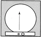
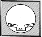
In a fluid discharge apparatus such as a solder bump forming apparatus using molten solder or an adhesive coating apparatus, as shown in fig. 1, a discharge head generally has the same size as a workpiece such as a silicon wafer or a printed circuit board, and the discharge head moves in a constant direction. In this way, the deflection of the mask due to the movement of the squeegee can be prevented with a smaller number of scans.
However, although there is no problem when the silicon wafer, the printed board, or the like is small, when the discharge head is used for a workpiece having a large size such as a 300mm silicon wafer, the length of the discharge head needs to be increased correspondingly to the workpiece. If the discharge head is made long, the pressure applied from the discharge head to the workpiece is not necessarily uniformly dispersed, and dispersion occurs. Therefore, the same amount of fluid cannot be discharged from the discharge head due to the deformation of the mask caused by the deflection due to the impact. Further, if the fluid is discharged a plurality of times using a small head, the adjacent discharge portions are close in the fine discharge pattern, and therefore the discharge is repeated, and the discharge amount is unstable.
Because of this, it is demanded to provide a fluid application device capable of applying a fluid at a stable discharge amount even in the case of discharging the fluid to a large-sized workpiece such as a 300mm silicon wafer. Furthermore, it is desirable to be able to apply the fluid to as large an area of the workpiece as possible.
Disclosure of Invention
The present invention is made to solve the above problems at least a part of the above-mentioned general formula (i), for example, the following embodiments can be realized.
According to the 1 st aspect of the present invention, there is provided a fluid discharge method for applying a fluid to a mask on a workpiece of an electronic component. In this method, a fluid discharge apparatus is used which has a head portion including a tank capable of storing a fluid and a discharge head having a width shorter than a length of a workpiece, in which a suction port for sucking a content of a mask on the workpiece and a discharge nozzle for discharging the fluid are formed near the suction port, and in which the suction port is arranged in front of a traveling direction of the discharge head, and the discharge head is reciprocated relative to the workpiece to perform discharge.
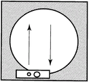
According to the embodiment 1, deformation of the mask can be reduced by reciprocating the discharge head with respect to the workpiece as shown in fig. 2. Specifically, the deformation of the mask, which occurs when the discharge head moves in the 1 st direction, is restored to the original shape by moving the once-deformed mask again in the 2 nd direction, which is the opposite direction of the 1 st direction, so that the deformation of the mask can be reduced.
According to the 2 nd aspect of the present invention, there is provided a fluid discharge apparatus for applying a fluid to a mask on a workpiece of an electronic component. The fluid discharge device is a head including a tank capable of receiving a fluid and a discharge head, and having a width shorter than a length of a workpiece; in the discharge head, suction ports are arranged on both sides of a discharge nozzle for discharging fluid in the vicinity of the discharge nozzle, the suction port is used for sucking the content of the mask on the workpiece and has a slit-shaped opening.
According to the embodiment 2, since the deformation of the mask is not biased in one direction and the deformation of the mask is reduced by performing the reciprocating discharge, the discharge amount is not deviated, and the fluid of a stable discharge amount can be discharged. Therefore, a large amount of correction generated when a fluid is applied to a fine mask in a workpiece in the past is not generated, the productivity is dramatically improved.
According to the 3 rd aspect of the present invention, there is provided a fluid discharge apparatus for applying a fluid to a mask on a workpiece of an electronic part. The fluid discharge device has a plurality of heads, including a tank capable of housing a fluid and a discharge head, smaller than a workpiece; the heads are moved in synchronization with each other in the horizontal direction on the workpiece; a suction port for sucking contents of the mask on the workpiece and a discharge nozzle for discharging a fluid in the vicinity thereof are formed in the discharge head, and the suction port is provided in front of the discharge head in the traveling direction; by degassing and depressurizing the air in the mask on the workpiece before discharging the fluid, the same amount of fluid can be stably discharged.
According to the 4 th aspect of the present invention, there is provided a fluid discharge method for coating a mask on a workpiece of an electronic component with a fluid. In the fluid discharge method, a plurality of heads are provided, the plurality of heads include a tank capable of receiving a fluid and a discharge head, are smaller than a workpiece, and are capable of changing an angle; the heads are moved in synchronization with each other in the horizontal direction on the workpiece; a suction port for sucking the content of the mask on the workpiece and a discharge nozzle for discharging fluid in the vicinity thereof are formed in the discharge head, and the suction port is provided in front of the discharge head in the traveling direction; by degassing and depressurizing the air in the mask on the workpiece before discharging the fluid, the same amount of fluid can be stably discharged.
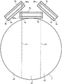
The plurality of divided heads may have a size in which a pressure from a vertical direction applied to the heads is uniformly applied. Specifically, the length of the workpiece is preferably 1/2 to 1/4 of the left-right length. The number of the plurality of heads used in the present application can be determined according to the size of the workpiece, but 2 to 4 heads are suitable for easy handling. In the case of discharging to a workpiece having a circular shape such as a silicon wafer, it is optimal to use 3 heads. As shown in fig. 6, in discharging a circular workpiece, the head is not only horizontally moved forward and backward, but also the angle of the head arranged on the left and right is changed along the circumference, so that even a circular workpiece which is more difficult to discharge than a square workpiece can be discharged with a uniform discharge amount.
According to the 4 th aspect, since the head is shorter than the workpiece, therefore, the pressure applied from the discharge head to the workpiece is not necessarily uniformly dispersed, and variation in the discharge amount is not generated, and uniform pressure can be applied to the workpiece. Further, since the heads move in the horizontal direction on the workpiece in synchronization with each other, there is no discharge omission, and a fluid of a stable discharge amount can be discharged. Therefore, the productivity is dramatically improved without a large amount of correction that has conventionally occurred when applying a fluid to a fine mask in a workpiece.
According to the 5 th aspect of the present invention, there is provided a fluid discharge device for applying a fluid to a workpiece of an electronic component. The fluid discharge device includes: 1 st stage for supporting a workpiece; a1 st discharge head configured to discharge a fluid while linearly moving in a horizontal direction above the stage, the 1 st discharge head being configured to move from an initial position outside the 1 st stage to a final position outside the 1 st stage via an upper side of the 1 st stage; a2 nd discharge head configured to discharge the fluid while changing an arrangement angle and moving in a horizontal direction above the 1 st stage; and a2 nd stage which is a2 nd stage arranged from the initial position to the outer edge of the 1 st stage and from the outer edge of the 1 st stage to the final position on the moving path of the 1 st discharge head, the discharge head being arranged slidably on the 2 nd stage. The range in which the fluid can be discharged in the 1 st discharge head and the 2 nd discharge head is smaller than the width of the region on the 1 st stage where the workpiece is disposed.
According to such a fluid discharge apparatus, since the fluid is discharged using a plurality of discharge heads smaller than the size of the workpiece, therefore, even when a large-sized workpiece is processed, the pressure applied from the discharge head to the workpiece is substantially equally distributed. Thus, the discharge amount of the discharge head is stabilized. Further, since the 2 nd moving stage is disposed outside the 1 st stage on the moving path of the 1 st discharge head, the 1 st discharge head can perform coating from the outer edge to the outer edge of the workpiece. Further, since the 2 nd discharge head moves while changing the arrangement angle, it is possible to discharge the fluid over a wide range even when the coating is started from the position on the work.
According to the 6 th aspect of the present invention, in the 5 th aspect, the 2 nd discharge head includes 2 discharge heads. The 2 discharge heads are arranged 1 on each side of the 1 st discharge head. According to this aspect, the fluid can be efficiently applied to substantially the entire area of the circular workpiece.
According to the 7 th aspect of the present invention, in the 5 th or 6 th aspect, the 1 st head and the 2 nd head are configured to move simultaneously in synchronization. According to this aspect, the processing time can be shortened.
According to the 8 th aspect of the present invention, in any one of the 5 th to 7 th aspects, the 1 st discharge head and the 2 nd discharge head are configured to cooperate with each other to cover a discharge target area on a workpiece substantially without overlapping. According to this aspect, the fluid can be efficiently applied. Further, since the fluid is not applied to the same portion a plurality of times, dispersion of the amount of application can be suppressed.
According to the 9 th aspect of the present invention, in any one of the 5 th to 8 th aspects, the range in which the fluid can be discharged in the 1 st head and the 2 nd head is 1/4 or more and 1/2 or less of the width of the region in which the workpiece is disposed on the 1 st stage. According to this aspect, the effect of the 5 th aspect can be obtained without excessively complicating the device configuration.
Drawings
Fig. 1 is a schematic view showing a discharge head of a conventional fluid application apparatus.
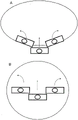
FIG. 2 shows an embodiment of the present invention a schematic view of a discharge head of the fluid application device of (1).
FIG. 3 is an embodiment according to the present invention the schematic configuration of the fluid application apparatus according to (1).
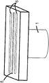
Fig. 4 is a schematic view illustrating a discharge head of a fluid application apparatus according to an embodiment of the present invention.
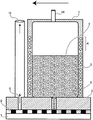
Fig. 5 is a detailed view illustrating a structure of a discharge head of a fluid application apparatus according to an embodiment of the present invention.
Fig. 6 is a schematic view illustrating a discharge head of a fluid application device according to embodiment 2 of the present invention.
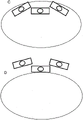
Fig. 7 is a diagram showing a moving path of the discharge head.
Fig. 8 is a diagram showing a moving path of the discharge head.
Fig. 9 is a diagram showing a moving path of the discharge head.
Fig. 10 is a diagram showing a moving path of the discharge head.
Fig. 11 is a diagram showing a moving path of the discharge head.
Fig. 12 is a plan view showing the arrangement of the discharge head and the stage of the fluid application device according to embodiment 3 of the present invention.
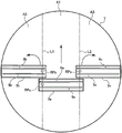
Fig. 13 is a sectional view showing the arrangement of the stage.
Fig. 14 is a diagram showing a moving path of the discharge head.
Fig. 15 is a diagram showing a moving path of the discharge head.
Fig. 16 is a diagram showing a moving path of the discharge head.
Detailed Description
A. Embodiment 1:
first, the structure of the discharge head 1 of the fluid application device is explained. Fig. 5 is a diagram showing details of the discharge head 1 according to the present invention. The discharge head 1 includes a fluid tank 2 capable of containing molten solder or the like and a discharge head 3 provided at a lower end. When the fluid tank is used for a fluid requiring temperature control such as molten solder, a heating mechanism such as a winding heater 4 may be attached to the belly of the fluid tank 2. On the discharge head 3, there are provided a fluid discharge nozzle 5 and a suction port 6 provided at the lower end of the head, the suction port 6 is installed toward the traveling direction than the fluid discharge nozzle 5 so that the suction process can be performed first. When the fluid discharge nozzle 5 and the suction port 6 are also used for a fluid requiring temperature control, the heater 4 may be attached to the lower end of the discharge head 3.
As the shape of the nozzle opening of the discharge head 3, round, slit, and other well-known shapes may also be used. In particular, if a slit shape is used as the shape of the nozzle opening, it is possible to discharge the fluid to the discharge targets on the plurality of workpieces 7 at the same time. The shape of the suction port 6 attached to the discharge head 3 may be a circular shape, a slit shape, or other known shapes, but by using a slit shape as the shape of the opening, air or a fluid that has been discharged from the mask 8 can be removed simultaneously from a workpiece 7 such as a silicon wafer or a printed board at a plurality of locations. Further, in the present application, as shown in fig. 4, by attaching the suction port 6 before and after the discharge head 3, the deformation of the mask can be made uniform, and the discharge can be performed in a stable reciprocating manner.
Next, the overall structure will be described. As shown in fig. 3, the fluid application apparatus of the present invention is movable in the up-down direction (Y) and also in the horizontal direction (X) so as to approach and depart as a whole with respect to the workpiece 7 of the electronic part to which the fluid is to be applied. On the upper part of the work 7, a mask 8 formed of polyimide or resist is placed. The discharge head 3 is lowered to a position where the fluid discharge nozzle 5 contacts the workpiece 7 at the time of fluid discharge. The liquid discharge head 3 is moved horizontally while maintaining the contact state of the fluid discharge nozzle 5 and the workpiece 7. If the discharge head 3 is moved horizontally, air inside the mask 8 provided on the workpiece 7 is first sucked by means of the suction port 6, the suction port 6 being installed toward the traveling direction so that the suction process can be performed first. Can utilize for the first time is discharged to the fluid within the mask 8 is also pumped in this stage. The fluid requiring the heating mechanism is heated by a heater 4 provided in a lower portion of the discharge head 3 and can be sucked. Then, if the liquid discharge head 3 is moved horizontally, the fluid is discharged from the openings of the fluid discharge nozzles 5, and the fluid is coated into the mask 8 on the workpiece 7. If the coating of the fluid is finished, the liquid discharge head 3 is lifted to be away from the workpiece 7. The same process can be performed without using the mask 8.
The fluid discharge device has a heater 4 for maintaining the fluid in the fluid tank 2 at a desired temperature. The heater 4 can be a component built into the wall of the fluid tank 2. The heater 4 is managed and controlled so as to be heated to a temperature suitable for maintaining the viscosity of the fluid 9 such as the molten solder in the fluid tank 2 optimal to the coating conditions.
Although not shown, the fluid discharge device is connected from the fluid tank 2 to a pressure supply mechanism 11 that can be in fluid communication via an extension line 10, and is connected to a pressure reduction supply mechanism 13 that can be in fluid communication via a suction tube extension line 12 that follows the suction port 6. The pressure supply mechanism 11 has a pressure generation source 14 that generates nitrogen gas at a pressure of, for example, 0.06 to 0.1MPa (not limited thereto). The pressure generation source 14 supplies pressure into the fluid tank 2 via the gate valve 15 and the three-way valve. The molten solder held in the fluid tank 2 is subjected to pressure from the pressure generation source 14 to be ejected from the opening of the fluid discharge nozzle 5.
The decompression supply mechanism 13 has a micro-ejector 16 as decompression generation means. The decompression generation device is connected to a pressure generation source 19 that generates nitrogen gas at a pressure of 0.4MPa (not limited thereto) via, for example, a regulator 17 and a throttle valve 18, and supplies negative pressure to the suction port 6 via the suction pipe extension line 12.
The fluid discharge device has a pressure sensor 20 and a control device 21. The pressure sensor 20 monitors the pressure in the fluid tank 2 by being connected to a three-way valve provided in the extension line 17 communicating with the fluid in the fluid tank 2. A signal indicative of the pressure in the fluid tank 2 is transmitted from the pressure sensor 20 to the control device 21. The controller 21 operates the pressure generation source 14, the decompression generation device, the regulator 17, the pressure generation source 19, and the valves according to the progress of the operation step, and supplies pressure into the fluid tank 2. An appropriate pressure value to be supplied is determined based on the signal from the pressure sensor 20. In the case of ejecting the molten solder in the fluid tank 2 from the opening of the fluid discharge nozzle 5, an operation is performed to bring the inside of the fluid tank 2 into fluid communication with the pressure sensor 20. The magnitude of the positive pressure supplied into the fluid tank 2 can be changed by adjusting the pressure value generated by the pressure generation source 14 by the control device 21, for example. Alternatively, the control device 21 may change the pressure value by adjusting a regulating valve (not shown) provided in the pressure supply mechanism 11.
In order to eject or hold the fluid such as the molten solder from the opening of the fluid discharge nozzle 5 in the fluid tank 2, the appropriate pressure value to be supplied into the fluid tank 2 is also affected by the amount (weight) of the molten solder contained in the fluid tank 2. Thus, the control device 21 may also be input with data regarding the amount of fluid in the fluid tank 2. In this case, the control device 21 can calculate a tank pressure value appropriate for discharge of the fluid or maintenance of the tank from the data of the amount of fluid in the fluid tank 2. Further, the control device 21 can compare the appropriate tank pressure value with the actual tank pressure value indicated by the signal from the pressure sensor 20, and adjust the pressure generation source 14 and the respective valves so that the appropriate tank pressure can be obtained.
In order to reduce as much as possible the variation in the appropriate tank internal pressure value due to the variation in the amount of fluid in the fluid tank 2, the fluid supply device 22 may be connected to the fluid tank 2. The fluid supply device 22 can automatically supply additional fluid so that the amount of fluid in the fluid tank 2 is always substantially constant when the molten solder in the fluid tank 2 is consumed during the operation of the fluid discharge device. In order to know the amount of fluid in the fluid tank 2, any well-known method may be used. The amount of molten solder in the fluid tank 2 can be estimated from the number of products processed and the like, and if the appropriate tank internal pressure value corresponding to the amount of fluid in the tank can be empirically known, the control device 21 can control the pressure to be supplied into the fluid tank 2 based only on the signal from the pressure sensor 20.
Finally, the operation of the fluid discharge device according to embodiment 1 will be described. The discharge head 3 of embodiment 1 is fixed at a fixed position apart from the workpiece 7, but when the fluid is discharged, the discharge head 3 moves in the vertical direction and also in the horizontal direction, and the discharge head 3 descends to a position where it contacts the discharge portion of the mask 8 on the workpiece 7. The pressure supplied from the pressure generation source 14 supplies the pressure into the fluid tank 2 via the gate valve 15. The fluid 9 held in the fluid tank 2 is subjected to pressure from the pressure generation source 14 and is ejected from the opening of the discharge nozzle 5. The discharge head 3 must be moved in the following manner: the discharge head 3 for discharging the fluid 9 is horizontally moved from the side where the suction nozzle is provided, and discharges the fluid from the discharge nozzle 5 after reducing the pressure of the air in the opening portion of the mask 8 on the workpiece 7. If the discharge of the fluid toward the opening of the mask 8 on the workpiece 7 in one direction is finished, the discharge head 3 folded back is then moved, and the discharge head 3 completes the reciprocating movement. According to such an operation, the discharge head 3 discharges the fluid while reciprocating with respect to the workpiece 7, so that the deformation of the mask is not biased in one direction and the deformation of the mask is reduced.
B. Embodiment 2:
hereinafter, embodiment 2 of the present invention will be mainly described focusing on differences from embodiment 1. The configuration of embodiment 2 is the same as embodiment 1, except for the point that this is not particularly negative.
The operation of the fluid discharge device according to embodiment 2 will be described. The discharge head 1 of embodiment 2 is fixed at a fixed position away from the workpiece 7, but when the fluid is discharged, the discharge head 1 moves in the vertical direction and also in the horizontal direction, and the discharge head 3 lowers to a position where it contacts the discharge portion of the mask 8 on the workpiece 7. Fig. 7A shows an example of a state in which the plurality of discharge heads 1 are lowered when discharging the fluid to the silicon wafer. The apparatus has 3 discharge heads 1, the center head being parallel to the traveling direction, and the left and right heads being disposed along a circular workpiece and being non-parallel to the traveling direction. In the state of descending from the initial position, the left head is rotated clockwise by 10 to 60 degrees, the center head is parallel to the workpiece, and the right head is rotated counterclockwise by 10 to 60 degrees. The front ends of the left and right heads on the center side of the workpiece are arranged more forward in the traveling direction than the discharge head 1 arranged at the center, and when the heads move horizontally in the traveling direction, the left head turns counterclockwise and the right head turns clockwise, and becomes approximately parallel to the traveling direction.
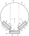
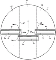
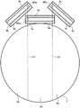
Fig. 7B shows an example of a state in which 3 discharge heads 1 are near the center of the silicon wafer. All the discharge heads 1 at the center and the left and right are parallel to each other in the traveling direction. If the 3 discharge heads 1 move across the center of the silicon wafer, the left head turns counterclockwise and the right head turns clockwise. Fig. 8C shows a state where the final position is reached. In the final position, the head portion on the left side is rotated counterclockwise by 10 to 60 degrees, the center head portion is parallel to the workpiece, and the head portion on the right side is rotated clockwise by 10 to 60 degrees. In this state, symmetrically to the initial position, the center discharge head 1 is parallel to the traveling direction, and the left and right heads are arranged along the circular workpiece and are not parallel to the traveling direction. The front ends of the left and right heads on the center side of the workpiece are arranged further forward in the traveling direction than the head arranged at the center. Fig. 8D shows a state where 3 heads are moved to the outside of the silicon wafer to remove the mask. In this position, as in fig. 8C, the center head is parallel to the traveling direction, and the left and right heads are arranged along the circular workpiece and are not parallel to the traveling direction. The front ends of the left and right heads on the center side of the workpiece are arranged further forward in the traveling direction than the head arranged at the center. The left and right heads of the fluid discharge device of the present application can turn 10 to 60 degrees toward the outer periphery on the workpiece while moving from the initial position to the final position.
In the present embodiment, the discharge head 3 moves in the following manner: the discharge head 3 for discharging the fluid 9 is horizontally moved from the side where the suction nozzle is provided, and the fluid is discharged from the discharge nozzle 5 after the air in the opening portion of the mask 8 on the workpiece 7 is decompressed. The pressure supplied from the pressure generation source 14 is supplied into the fluid tank 2 via the gate valve 15. The fluid 9 held in the fluid tank 2 is subjected to pressure from the pressure generation source 14 and is ejected from the opening of the discharge nozzle 5. The discharge head 3 moves horizontally so as to be drawn over the mask 8 of the workpiece 7, and the application of the fluid of the determined range is completed. According to such an operation, by discharging the fluid using the plurality of discharge heads 3 smaller than the size of the workpiece 7, variation in the discharge amount can be suppressed, and the discharge amount can be stabilized.
Fig. 9 to 11 show specific examples of the moving paths of the discharge heads 3a to 3c. Fig. 9 shows initial positions of the discharge heads 3a to 3c before scanning. The 1 st discharge head 3a is arranged outside the workpiece 7. The longer direction of the 1 st discharge head 3a is perpendicular to the traveling direction of the 1 st discharge head 3a (direction toward the upper side of the paper surface). The 2 nd discharge heads 3b and 3c are arranged so as to contact the inner periphery of the circular workpiece 7. In other words, the 2 nd discharge head 3b or 3c is disposed forward in the traveling direction of the 1 st discharge head 3 a. The longer direction of the 2 nd discharge heads 3b and 3c is inclined with respect to the traveling direction of the discharge heads 3a to 3c (direction toward the upper side of the paper surface). The inclination may be, for example, an angle of 10 to 60 degrees with respect to the traveling direction. The 2 nd discharge head 3b revolves counterclockwise as it advances in the traveling direction, and the 2 nd discharge head 3c revolves clockwise as it advances in the traveling direction. The operation of the 2 nd discharge heads 3b and 3c to advance in the traveling direction while rotating can be realized by, for example, a robot arm.
Fig. 10 shows intermediate positions in scanning by the discharge heads 3a to 3c. The 1 st discharge head 3a is linearly moved from the initial position shown in fig. 9 to the center of the workpiece 7. The reference point RPa of the 1 st discharge head 3a moves along the straight line L1. The 2 nd discharge heads 3b and 3c are arranged at the same arrangement angle as the 1 st discharge head 3a by rotating from the initial position shown in fig. 9 and advancing in the traveling direction. That is, the longer direction of the 1 st head 3a and the longer direction of the 2 nd heads 3b, 3c are parallel. In this rotation movement, the reference points RPb and RPc of the 2 nd discharge heads 3b and 3c move along the straight lines L1 and L2, respectively. The reference points RPb and RPc are set at the 1 st head 3 a-side end of the discharge nozzle 5.
Fig. 11 shows the final positions of the discharge heads 3a to 3c after the scanning is finished. The 1 st discharge head 3a is moved from the intermediate position shown in fig. 10 to a position outside the workpiece 7 (outside on the side opposite to the initial position). The 2 nd discharge heads 3b and 3c advance in the traveling direction while rotating from the intermediate position shown in fig. 10, and are inclined with respect to the traveling direction of the discharge heads 3a to 3c (the direction toward the upper side of the paper surface). The inclination is an inclination opposite to the inclination at the initial position. The inclination may be, for example, an angle of 10 to 60 degrees with respect to the traveling direction.
In this way, the discharge heads 3a to 3c are moved, so that the fluid 9 can be applied to substantially the entire area of the workpiece 7. Specifically, the coating in the region A1 in the center is covered by the 1 st discharge head 3a, the coating in the region A2 on the left side is covered by the 2 nd discharge head 3b on the left side, and the coating in the region A3 on the right side is covered by the 2 nd discharge head 3c on the right side. The formation region of the discharge nozzles 5a to 5c of the discharge heads 3a to 3c may be adjusted and the reference positions RP1 to RP3 may be adjusted so that the discharge region on the workpiece 7 is substantially covered without overlapping.
C. Embodiment 3:
embodiment 3 of the present invention will be described below. Fig. 3 is a schematic diagram showing a schematic configuration of a solder bump forming apparatus as an example of the fluid application apparatus of embodiment 3. The solder bump forming apparatus is an apparatus for forming a solder bump by applying a fluid 9 (molten solder in this case) onto a workpiece 7 (e.g., a silicon wafer, a printed circuit board, or the like) of an electronic component. As shown in fig. 3, the solder bump forming apparatus includes a discharge head 1, a pressure supply mechanism 11, a pressure generation source 14, a micro-ejector 16, a pressure generation source 19, and a fluid supply device 22. The solder bump forming apparatus further includes stages 30 to 32 (see fig. 12). Details of these components are described later.
Fig. 5 is a schematic view showing the discharge head 1 of the solder bump forming apparatus. As shown in fig. 5, the discharge head 1 includes a fluid tank 2 capable of storing a fluid 9, and a discharge head 3 provided at a lower end of the fluid tank 2. The discharge head 1 is configured to be movable in a horizontal direction above the workpiece 7 by an arbitrary actuator (not shown). In the present embodiment, the discharge head 1 is slidably moved on the mask 8 disposed on the workpiece 7. The mask 8 has a plurality of hole portions formed at portions where solder bumps are to be formed. These holes penetrate the mask 8 in the thickness direction (vertical direction). The mask 8 may be made of polyimide or resist, for example. Furthermore, it is possible to provide a liquid crystal display device, the discharge head 1 is configured to be movable in the vertical direction, that is, so as to approach and separate from the workpiece 7.
The fluid tank 2 is shown in figure 3, or may be connected to the fluid supply 22. The fluid supply device 22 can automatically supply the fluid 9 when the fluid 9 in the fluid tank 2 is consumed, so that the amount of fluid stored in the fluid tank 2 is always substantially constant. With this configuration, it is possible to suppress variation in the pressure in the fluid tank 2 due to variation in the amount of fluid stored in the tank.
In the present embodiment, the discharge head 1 includes the heater 4 for maintaining the fluid 9 in the fluid tank 2 at a desired temperature. The heater 4 may also be built into the wall of the fluid tank 2. The heater 4 is controlled so as to heat the fluid 9 to a temperature suitable for maintaining an optimal viscosity of the fluid 9 inside the fluid tank 2 with respect to the coating conditions.
As shown in fig. 5, the discharge head 3 has a discharge nozzle 5 and a suction port 6. The discharge nozzle 5 penetrates the discharge head 3 in the vertical direction, and communicates with the fluid tank 2. As shown in fig. 3, the fluid tank 2 is connected to a pressure supply mechanism 11 via an extension line 10. The pressure supply mechanism 11 includes a pressure generation source 14 that generates nitrogen gas at a pressure of, for example, 0.06 to 0.1MPa (not limited thereto). The pressure generation source 14 supplies pressure to the discharge head 1 via a gate valve and a three-way valve. The fluid 9 in the fluid tank 2 is discharged from the discharge nozzle 5 by this pressure.
As shown in fig. 5, the suction port 6 penetrates the discharge head 3 in the vertical direction and communicates with the suction pipe extension line 12. As shown in fig. 3, the suction-pipe extension line 12 is connected to the decompression supply mechanism 13. The decompression supply mechanism 13 includes a micro-ejector 16 as a decompression generation means. The micro-ejector 16 is connected to a pressure generation source 19 that generates nitrogen gas at a pressure of 0.4MPa (not limited thereto) via, for example, a regulator and a throttle valve 18. The negative pressure is supplied to the suction port 6 through the suction-pipe extension pipe 12 by the decompression supply mechanism 13.
The suction port 6 is disposed forward of the discharge nozzle 5 in the traveling direction of the discharge head 1. Therefore, before the fluid is discharged from the discharge nozzle 5, the inside of the hole portion of the mask 8 can be degassed/decompressed by the suction port 6. This enables stable discharge of the same amount of fluid.
The opening shape of the discharge nozzle 5 may be a circular shape, a slit shape, or other known shapes. In particular, if the discharge nozzle 5 is formed in a slit shape as an opening shape, the fluid can be discharged into the plurality of holes of the mask 8 at the same time. The opening of the suction port 6 may be circular, slit, or other known shapes. When the opening shape of the suction port 6 is a slit shape, air or discharged fluid can be sucked simultaneously at a plurality of locations.
The outline of the operation of the above-described solder bump forming apparatus will be described below. When the discharge head 1 discharges the fluid, the discharge head 3 (i.e., the opening portion located at the lower end of the discharge nozzle 5) is lowered to a position in contact with the mask 8. The discharge head 3 is moved in the horizontal direction while maintaining the contact state of the discharge nozzle 5 and the mask 8. If the discharge head 3 is moved horizontally, first, air in the hole portion of the mask 8 disposed on the workpiece 7 is sucked from the suction port 6 disposed forward in the traveling direction of the discharge head 3. Further, in the case where the discharge head 3 scans on the same hole portion a plurality of times, the fluid 9 which has been discharged into the hole portion before is also sucked in this stage. A heater may be disposed below the discharge head 3. If this is done, the fluid 9 that was previously discharged into the hole portion does not solidify, so the fluid can be reliably sucked. Then, if the discharge head 3 is further moved horizontally, the fluid 9 is discharged from the opening of the discharge nozzle 5 into the hole portion of the mask 8 which has been sucked by the suction port 6. Thereby, the fluid 9 is applied into the hole portions of the mask 8 on the workpiece 7. If the coating of the fluid 9 is finished, the discharge head 3 is lifted so as to be away from the mask 8. The same process can be performed without using the mask 8.
Fig. 12 is a plan view showing the arrangement of the discharge head 1, the 1 st stage 30, and the 2 nd stages 31 and 32. As shown in fig. 12, the solder bump forming apparatus of the present embodiment includes 3 discharge heads 3a to 3c. Actually, the number of the discharge heads 1 is also 3, but the illustration thereof is omitted in fig. 12. Note that illustration of the mask 8 is also omitted. In the present embodiment, focusing on the difference in the moving form of the discharge heads 3a to 3c, the discharge head 3a is also referred to as the 1 st discharge head 3a, and the discharge heads 3b and 3c are also referred to as the 2 nd discharge heads 3b and 3c. The solder bump forming apparatus includes a1 st stage 30 for supporting the workpiece 7, and 2 nd stages 31 and 32 disposed outside the 1 st stage 30.
In the present embodiment, the 1 st stage 30 has a circular shape slightly larger than the circular workpiece 7. However, the shape of the 1 st stage 30 may have any shape according to the shape of the workpiece 7. The 2 nd stages 31 and 32 are disposed to face both ends of the 1 st stage 30 in the radial direction so as to contact the outer edge of the 1 st stage 30. In the present embodiment, the 2 nd stages 31, 32 have a rectangular shape. However, the 2 nd stages 31 and 32 may have any shape extending to the outer edge of the 1 st stage 30. For example, the 2 nd stages 31 and 32 may have a concave shape having an arc conforming to the arc shape of the outer edge of the 1 st stage 30.
Fig. 13 is a sectional view showing the arrangement of the 1 st stage 30 and the 2 nd stages 31 and 32. As shown in fig. 13, the 1 st stage 30 has a recess in the center thereof for disposing the workpiece 7. The recess is formed in such a size that the upper end of the recess coincides with the upper end of the mask 8 when the workpiece 7 and the mask 8 are disposed in the recess. The upper ends of the 2 nd stages 31 and 32 are at the same height as the upper end of the recess of the 1 st stage 30 and the upper end of the mask 8. Thus, the first discharge head 3a described later can be moved to slide in the horizontal direction while contacting the upper surfaces of the stages 30 to 32 and the mask 8.
The 1 st discharge head 3a is configured to move in the horizontal direction above the workpiece 7. Specifically, the 1 st discharge head 3a moves linearly from an initial position outside the 1 st stage 30 (position on the 2 nd stage 31) to a final position outside the 1 st stage 30 (position on the 2 nd stage 32) through the center of the workpiece 7.
The 2 nd discharge heads 3b and 3c are disposed on both sides of the 1 st discharge head 3a, respectively. The 2 nd discharge heads 3b and 3c move in the same traveling direction as the 1 st discharge head 3a above the workpiece 7 while changing the arrangement angle.
The widths of the discharge heads 3a to 3c in the longitudinal direction (in other words, the ranges within which the fluid 9 can be discharged from the discharge heads 3a to 3 c) are all smaller than the width of the workpiece 7 (in other words, the region in which the workpiece 7 is disposed). Therefore, the discharge heads 3a to 3c cooperate with each other to apply the fluid 9 to the entire area of the workpiece 7. In other words, the discharge heads 3a to 3c respectively apply the fluid 9 to different areas, thereby applying the fluid 9 to the entire area of the workpiece 7. The widths of the discharge heads 3a to 3c may be 1/4 to 1/2 of the width of the region where the workpiece 7 is disposed. If this is done, the fluid 9 can be uniformly coated without unduly complicating the device structure.
Fig. 14 to 16 show specific examples of the movement paths of the discharge heads 3a to 3c. Fig. 14 shows initial positions of the discharge heads 3a to 3c before scanning. The 1 st discharge head 3a is disposed on the 2 nd stage 31 (not shown in fig. 14). The longer direction of the 1 st head 3a is perpendicular to the traveling direction (direction toward the upper side of the paper surface) of the 1 st head 3 a. The 2 nd discharge heads 3b, 3c are arranged so as to contact the inner periphery of the circular workpiece 7. In other words, the 2 nd discharge head 3b or 3c is disposed forward in the traveling direction of the 1 st discharge head 3 a. The longer direction of the 2 nd discharge heads 3b and 3c is inclined with respect to the traveling direction of the discharge heads 3a to 3c (direction toward the upper side of the paper surface). The inclination may be, for example, an angle of 10 to 60 degrees with respect to the traveling direction. The 2 nd discharge head 3b revolves counterclockwise as it advances in the traveling direction, and the 2 nd discharge head 3c revolves clockwise as it advances in the traveling direction. The operation of the 2 nd discharge heads 3b and 3c to advance in the traveling direction while rotating can be realized by, for example, a robot arm.
Fig. 15 shows an intermediate position in the scanning of the discharge heads 3a to 3c. The 1 st discharge head 3a is linearly moved from the initial position shown in fig. 14 to the center of the workpiece 7. The reference point RPa of the 1 st discharge head 3a moves along the straight line L1. The 2 nd discharge heads 3b and 3c are arranged at the same arrangement angle as the 1 st discharge head 3a by rotating from the initial position shown in fig. 14 and advancing in the traveling direction. That is, the longer direction of the 1 st head 3a is parallel to the longer direction of the 2 nd heads 3b, 3c. In this rotation movement, the reference points RPb and RPc of the 2 nd discharge heads 3b and 3c move along the straight lines L1 and L2, respectively. In addition, the first and second substrates are, the reference points RPb, RPc are set at the 1 st head 3a side end of the discharge nozzle 5.
Fig. 16 shows the final positions of the discharge heads 3a to 3c after the scanning is finished. The 1 st discharge head 3a moves from the intermediate position shown in fig. 15 to a position on the 2 nd stage 32 (not shown in fig. 16). The 2 nd discharge heads 3b and 3c advance in the traveling direction while rotating from the intermediate position shown in fig. 15, and are inclined with respect to the traveling direction of the discharge heads 3a to 3c (the direction toward the upper side of the paper surface). The inclination is an inclination opposite to the inclination at the initial position. The inclination may be, for example, an angle of 10 to 60 degrees with respect to the traveling direction.
In this way, the discharge heads 3a to 3c are moved, so that the fluid 9 can be applied to substantially the entire area of the workpiece 7. Specifically, the coating in the area A1 in the center is covered by the 1 st discharge head 3a, the coating in the area A2 on the left side is covered by the 2 nd discharge head 3b on the left side, and the coating in the area A3 on the right side is covered by the 2 nd discharge head 3c on the right side. The formation region of the discharge nozzles 5a to 5c of the discharge heads 3a to 3c may be adjusted and the reference positions RP1 to RP3 may be adjusted so that the discharge region on the workpiece 7 is substantially covered without overlapping.
The above-described movements of the discharge heads 3a to 3c may be performed simultaneously in synchronization with each other. By doing so, the processing time of the workpiece 7 can be shortened. However, after the movement of at least 1 of the discharge heads 3a to 3c is completed, the remaining discharge heads 3a to 3c may start to move.
According to the above-described solder bump forming apparatus, since the fluid 9 is discharged by using the plurality of discharge heads 3a to 3c smaller than the size of the workpiece 7, even when the workpiece 7 is large, the pressures applied to the workpiece 7 from the respective discharge heads 3a to 3c are substantially equally distributed. Therefore, the discharge amount of the fluid 9 can be made uniform. Further, since the 2 nd stages 31 and 32 are arranged outside the 1 st stage 30 on the moving path of the 1 st discharge head 3a, the 1 st discharge head 3a can perform coating from the outer edge to the outer edge of the workpiece 7. Further, since the 2 nd discharge heads 3b and 3c move while changing the arrangement angle, the fluid 9 can be discharged over a wide range even when coating is started from a position on the workpiece 7. Therefore, the fluid 9 can be discharged over a wide area of the workpiece 7. In particular, by using the 1 st discharge head 3a and the 2 nd discharge heads 3b, 3c as in the present embodiment, it is possible to efficiently apply the fluid to substantially the entire area of the circular workpiece 7. However, the number of the discharge heads 3 can be set to any number of 2 or more depending on the size and shape of the workpiece 7.
Description of the reference numerals
1. Discharge head
2. Fluid tank
3. 3a, 3b, 3c discharge head
4. Heating apparatus
5. Discharge nozzle
6. Suction opening
7. Workpiece
8. Mask and method for manufacturing the same
9. Fluid, especially for a motor vehicle
10. Extension pipeline
11. Pressure supply mechanism
12. Suction tube extension line
13. Pressure reducing supply mechanism
14. Pressure generating source
16. Micro-ejector
18. Throttle valve
19. Pressure generating source
22. Fluid supply device
30. 1 st stage
31. 32 nd station 2.
Claims (13)
1. A fluid discharge method for applying a fluid to a mask on a circular workpiece of an electronic part, the fluid discharge method being characterized in that,
using a fluid discharge apparatus having a head portion including a tank provided with a1 st heater capable of storing the fluid and a discharge head having a longer-direction width shorter than a diameter of the workpiece, the discharge head having a suction port formed in a front portion in a traveling direction of the discharge head for sucking contents of a mask on the workpiece and a discharge nozzle formed in a rear portion in the traveling direction for discharging the fluid, the discharge nozzle being provided at a lower end thereof with a2 nd heater configured to heat the fluid in the mask; the fluid is discharged from the discharge nozzle after the air and the fluid in the mask are sucked from the suction port by reciprocating the discharge head with respect to the workpiece.
2. The fluid discharge method according to claim 1,
the discharge head has an opening portion having a slit shape as the discharge nozzle and the suction port.
3. The fluid discharge method according to claim 1,
suction ports are disposed on both sides of the discharge head with the discharge nozzle interposed therebetween.
4. A solder bump forming apparatus for forming solder bumps by applying molten solder to a mask on a circular silicon wafer of an electronic part, the solder bump forming apparatus being characterized in that,
the disclosed device is provided with:
a head part including a tank capable of accommodating the molten solder and a discharge head, the head part having a longer width than a diameter of the silicon wafer;
a1 st heater provided in the tank, for heating the molten solder in the tank to be dischargeable;
the discharge head is provided with discharge nozzles for discharging the molten solder and suction ports disposed in the vicinity of the discharge nozzles on both sides of the discharge nozzles, the suction ports being provided for sucking the content of the mask on the silicon wafer and having slit-like openings,
a2 nd heater configured to heat the fluid in the mask is provided at a lower end of the discharge head,
the discharge head is configured to move over the mask so as to suck the fluid in the mask by reducing the pressure of the air in the opening of the mask by sucking the fluid from the suction port, and then to discharge the molten solder from the discharge nozzle.
5. A fluid ejection device for applying a fluid to a mask on a circular workpiece of an electronic part,
a plurality of heads having a width in a longitudinal direction smaller than a diameter of the workpiece;
the plurality of heads include: a1 st head configured to linearly move in a horizontal direction above the workpiece; a2 nd head moving in a horizontal direction while rotating above the workpiece in synchronization with the 1 st head;
the 1 st head and the 2 nd head each include a tank provided with a1 st heater and a discharge head capable of storing a fluid;
a suction port for sucking the content of the mask on the workpiece is formed in the discharge head in front of the discharge head in the traveling direction, and a discharge nozzle for discharging the fluid is formed in the discharge head behind the suction port in the traveling direction;
a2 nd heater configured to heat the fluid in the mask is provided in the vicinity of the discharge nozzle and the suction port;
the discharge head is configured to discharge the fluid from the discharge nozzle and suck the air and the fluid in the mask from the suction port while moving in a horizontal direction above the workpiece.
6. The fluid evacuation device of claim 5,
the 2 nd header includes 2 nd headers disposed on both sides of the 1 st header.
7. The fluid evacuation device of claim 5,
the suction port has 2 suction ports disposed on both sides of the discharge nozzle.
8. The fluid evacuation device of claim 6,
the 2 nd head has a head that revolves counterclockwise and a head that revolves clockwise.
9. A fluid discharge apparatus for applying a fluid into a mask on a circular workpiece of an electronic component, the fluid discharge apparatus comprising:
a table for supporting the workpiece; and
a1 st, a2 nd, and a3 rd discharge heads configured to discharge the fluid while moving in a horizontal direction above the stage;
the 1 st discharge head is configured to move linearly from an initial position outside the stage to a final position outside the stage via above the stage;
the 2 nd discharge head is configured to discharge the fluid while being arranged on the left side in the traveling direction of the 1 st discharge head, rotating counterclockwise, and moving in the horizontal direction above the table;
the 3 rd discharge head is configured to discharge the fluid while being arranged on the right side in the traveling direction of the 1 st discharge head and rotating clockwise and moving horizontally above the table;
a range in which the fluid can be discharged in the 1 st, 2 nd, and 3 rd discharge heads is smaller than a width of a region in which the workpiece is disposed on the stage;
setting a reference point at an end portion of the discharge nozzles formed in the 2 nd and 3 rd discharge heads on the 1 st discharge head side on the 2 nd and 3 rd discharge heads;
the reference point describes a linear path along the moving direction of the 2 nd and 3 rd discharge heads when the 2 nd and 3 rd discharge heads move,
the 1 st, 2 nd and 3 rd discharge heads each have a tank provided with a1 st heater capable of containing a fluid and a discharge nozzle,
a2 nd heater configured to heat the fluid in the mask is provided at a lower end of the discharge nozzle of each of the 1 st, 2 nd, and 3 rd discharge heads.
10. A fluid discharge apparatus for applying a fluid into a mask on a circular workpiece of an electronic part, said fluid discharge apparatus being characterized in that,
the fluid discharge device is provided with:
a table for supporting the workpiece; and
a1 st, a2 nd, and a3 rd discharge heads configured to discharge the fluid while moving in a horizontal direction above the stage;
the 1 st discharge head is configured to move linearly from an initial position outside the stage to a final position outside the stage via above the stage;
the 2 nd discharge head is configured to discharge the fluid while being arranged on the left side in the traveling direction of the 1 st discharge head and rotating counterclockwise and moving in the horizontal direction above the table;
the 3 rd discharge head is configured to discharge the fluid while being arranged on the right side in the traveling direction of the 1 st discharge head and rotating clockwise and moving horizontally above the table;
the range of the 1 st, 2 nd and 3 rd discharge heads capable of discharging the fluid is smaller than the width of the region on the table where the workpiece is disposed,
the 1 st, 2 nd and 3 rd discharge heads each have a tank provided with a1 st heater capable of containing a fluid and a discharge nozzle,
a2 nd heater configured to heat the fluid in the mask is provided at a lower end of the discharge nozzle of each of the 1 st, 2 nd, and 3 rd discharge heads.
11. The fluid evacuation device of claim 9 or 10,
the 1 st head and the 2 nd and 3 rd heads are configured to move simultaneously in synchronization.
12. The fluid evacuation device of claim 9 or 10,
the 1 st, 2 nd and 3 rd discharge heads are configured to cooperate with each other to cover a discharge region of the workpiece substantially without overlapping.
13. The fluid evacuation device of claim 9 or 10,
the 1 st discharge head and the 2 nd discharge head the range of the 3 rd discharge head capable of discharging the fluid is 1/4 to 1/2 of the width of the region on the 1 st stage where the workpiece is disposed.
Applications Claiming Priority (7)
| Application Number | Priority Date | Filing Date | Title |
|---|---|---|---|
| JP2015244139 | 2015-12-15 | ||
| JP2015-244141 | 2015-12-15 | ||
| JP2015244141 | 2015-12-15 | ||
| JP2015-244139 | 2015-12-15 | ||
| JP2016-165458 | 2016-08-26 | ||
| JP2016165458 | 2016-08-26 | ||
| PCT/JP2016/087369 WO2017104745A1 (en) | 2015-12-15 | 2016-12-15 | Fluid discharging device and fluid discharging method |
Publications (2)
| Publication Number | Publication Date |
|---|---|
| CN108602088A CN108602088A (en) | 2018-09-28 |
| CN108602088B true CN108602088B (en) | 2022-10-14 |
Family
ID=59056589
Family Applications (1)
| Application Number | Title | Priority Date | Filing Date |
|---|---|---|---|
| CN201680074153.8A Active CN108602088B (en) | 2015-12-15 | 2016-12-15 | Fluid discharge device and fluid discharge method |
Country Status (8)
| Country | Link |
|---|---|
| US (2) | US10932372B2 (en) |
| EP (1) | EP3391974B1 (en) |
| JP (2) | JP6579343B2 (en) |
| KR (1) | KR102596840B1 (en) |
| CN (1) | CN108602088B (en) |
| HU (1) | HUE059602T2 (en) |
| TW (2) | TWI708346B (en) |
| WO (1) | WO2017104745A1 (en) |
Families Citing this family (2)
| Publication number | Priority date | Publication date | Assignee | Title |
|---|---|---|---|---|
| US11298769B2 (en) * | 2019-05-13 | 2022-04-12 | International Business Machines Corporation | Prevention of dripping of material for material injection |
| CN116321788B (en) * | 2021-10-13 | 2024-02-06 | 苏州康尼格电子科技股份有限公司 | PCBA (printed circuit board assembly) board packaging equipment and PCBA board packaging method |
Citations (5)
| Publication number | Priority date | Publication date | Assignee | Title |
|---|---|---|---|---|
| CN1796000A (en) * | 2004-12-28 | 2006-07-05 | Lg.菲利浦Lcd株式会社 | Slit coater having apparatus for supplying a coating solution |
| CN101668876A (en) * | 2007-04-26 | 2010-03-10 | 气体产品与化学公司 | Apparatuses and methods for cryogenic cooling in thermal surface treatment processes |
| CN103785580A (en) * | 2012-10-26 | 2014-05-14 | 诺信公司 | Adhesive dispensing system and method with melt on demand at point of dispensing |
| CN103985640A (en) * | 2013-02-11 | 2014-08-13 | 国际商业机器公司 | Fill head apparatus |
| JP2014157863A (en) * | 2013-02-14 | 2014-08-28 | Tokyo Electron Ltd | Metallic paste filling method and metallic paste filling device |
Family Cites Families (43)
| Publication number | Priority date | Publication date | Assignee | Title |
|---|---|---|---|---|
| JPS55154798A (en) * | 1979-05-21 | 1980-12-02 | Sony Corp | Apparatus for fabricating hybrid integrated circuit |
| US4517917A (en) * | 1984-04-26 | 1985-05-21 | Valco Cincinnati, Inc. | Blow-off manifold for preventing trailing from a non-contact extrusion adhesive application valve |
| US4934309A (en) | 1988-04-15 | 1990-06-19 | International Business Machines Corporation | Solder deposition system |
| US4898117A (en) | 1988-04-15 | 1990-02-06 | International Business Machines Corporation | Solder deposition system |
| US5418009A (en) * | 1992-07-08 | 1995-05-23 | Nordson Corporation | Apparatus and methods for intermittently applying discrete adhesive coatings |
| JPH06151296A (en) * | 1992-11-11 | 1994-05-31 | Yamaha Corp | Method and device for high pressure supply |
| US5478700A (en) | 1993-12-21 | 1995-12-26 | International Business Machines Corporation | Method for applying bonding agents to pad and/or interconnection sites in the manufacture of electrical circuits using a bonding agent injection head |
| US6231333B1 (en) * | 1995-08-24 | 2001-05-15 | International Business Machines Corporation | Apparatus and method for vacuum injection molding |
| US6149076A (en) * | 1998-08-05 | 2000-11-21 | Nordson Corporation | Dispensing apparatus having nozzle for controlling heated liquid discharge with unheated pressurized air |
| US6461136B1 (en) * | 1999-08-26 | 2002-10-08 | International Business Machines Corp. | Apparatus for filling high aspect ratio via holes in electronic substrates |
| FI115295B (en) * | 1999-09-01 | 2005-04-15 | Metso Paper Inc | Curtain coating device and curtain coating method |
| FR2803228B1 (en) * | 2000-01-03 | 2002-02-08 | Novatec Sa Soc | COLLECTIVE FILLING DEVICE OF BORGNATED CAVITIES |
| JP2001269610A (en) * | 2000-01-17 | 2001-10-02 | Canon Inc | Coating method, coating device and method of forming coating film |
| US6544590B1 (en) | 2000-01-17 | 2003-04-08 | Canon Kabushiki Kaisha | Liquid coating method, apparatus and film-forming method for producing the same employing excess coating removing unit having absorbent fabric on porous structure |
| US6638363B2 (en) * | 2000-11-22 | 2003-10-28 | Gunter Erdmann | Method of cleaning solder paste |
| US6692165B2 (en) | 2001-03-01 | 2004-02-17 | Dainippon Screen Mfg. Co., Ltd. | Substrate processing apparatus |
| JP3957983B2 (en) * | 2001-03-01 | 2007-08-15 | 大日本スクリーン製造株式会社 | Substrate developing device |
| US20040202863A1 (en) * | 2002-02-26 | 2004-10-14 | Konica Corporation | Coating method, coated product and ink jet recording medium |
| JP3849545B2 (en) | 2002-02-26 | 2006-11-22 | セイコーエプソン株式会社 | Thin film forming apparatus and thin film forming method, circuit pattern manufacturing apparatus, circuit pattern manufacturing method and electronic apparatus, resist pattern manufacturing apparatus and resist pattern manufacturing method |
| JP3619874B2 (en) | 2002-07-05 | 2005-02-16 | 国立大学法人京都大学 | Temperature-responsive polymer and temperature-responsive gel polymer |
| JP4127008B2 (en) * | 2002-10-03 | 2008-07-30 | セイコーエプソン株式会社 | Droplet ejection apparatus and method, device manufacturing apparatus, device manufacturing method, and electronic apparatus |
| JP4432322B2 (en) * | 2003-01-20 | 2010-03-17 | セイコーエプソン株式会社 | Droplet discharge device |
| JP3772155B2 (en) * | 2003-04-01 | 2006-05-10 | 株式会社タムラ製作所 | Liquid ejector |
| JP2004337704A (en) * | 2003-05-14 | 2004-12-02 | Seiko Epson Corp | Droplet discharging apparatus |
| KR100958573B1 (en) * | 2003-10-06 | 2010-05-18 | 엘지디스플레이 주식회사 | Fabrication apparatus and method of liquid crystal display panel |
| JP2005183542A (en) * | 2003-12-17 | 2005-07-07 | Fujikura Ltd | Solder coating method of printed wiring board |
| JP2005246139A (en) * | 2004-03-01 | 2005-09-15 | Seiko Epson Corp | Method and apparatus for applying fluid material, and electronic device |
| US7354869B2 (en) | 2004-04-13 | 2008-04-08 | Kabushiki Kaisha Toshiba | Substrate processing method, substrate processing apparatus, and semiconductor device manufacturing method |
| JP2006013228A (en) * | 2004-06-28 | 2006-01-12 | Toshiba Corp | Substrate processing method and substrate processor |
| JP4271109B2 (en) * | 2004-09-10 | 2009-06-03 | 東京エレクトロン株式会社 | Coating, developing device, resist pattern forming method, exposure device and cleaning device |
| US7291226B2 (en) * | 2004-09-30 | 2007-11-06 | Lexmark International, Inc. | Progressive stencil printing |
| US8287647B2 (en) * | 2007-04-17 | 2012-10-16 | Lam Research Corporation | Apparatus and method for atomic layer deposition |
| DE102007053513B3 (en) * | 2007-11-09 | 2009-07-16 | Itc Intercircuit Electronic Gmbh | filling station |
| EP2555923B1 (en) * | 2010-04-05 | 2017-08-09 | DTG International GmbH | Screen cleaning apparatus and method |
| JP2012139655A (en) * | 2011-01-05 | 2012-07-26 | Seiko Epson Corp | Printing apparatus |
| TWI552824B (en) | 2011-10-18 | 2016-10-11 | 千住金屬工業股份有限公司 | Method and apparatus for forming solder bump |
| US8789490B2 (en) * | 2012-01-20 | 2014-07-29 | Sso Venture Partners, Llc | System and method of pointillist painting |
| JP5732023B2 (en) | 2012-10-31 | 2015-06-10 | ヤマハ発動機株式会社 | Solder supply method and solder supply apparatus |
| JP6393462B2 (en) * | 2013-09-11 | 2018-09-19 | 東レエンジニアリング株式会社 | Electrospray equipment |
| JP6276552B2 (en) * | 2013-10-04 | 2018-02-07 | ファスフォードテクノロジ株式会社 | Die bonder and adhesive coating method |
| US10632492B2 (en) * | 2015-01-13 | 2020-04-28 | Senju Metal Industry Co., Ltd. | Fluid discharge device, fluid discharge method, and fluid application device |
| KR20180095864A (en) * | 2015-12-15 | 2018-08-28 | 센주긴조쿠고교 가부시키가이샤 | How to modify the solder bump |
| JP2017109211A (en) * | 2015-12-15 | 2017-06-22 | 千住金属工業株式会社 | Fluid discharge method and fluid discharge device |
-
2016
- 2016-12-15 EP EP16875722.7A patent/EP3391974B1/en active Active
- 2016-12-15 HU HUE16875722A patent/HUE059602T2/en unknown
- 2016-12-15 CN CN201680074153.8A patent/CN108602088B/en active Active
- 2016-12-15 WO PCT/JP2016/087369 patent/WO2017104745A1/en active Application Filing
- 2016-12-15 TW TW105141593A patent/TWI708346B/en active
- 2016-12-15 KR KR1020187020103A patent/KR102596840B1/en active IP Right Grant
- 2016-12-15 US US16/063,155 patent/US10932372B2/en active Active
- 2016-12-15 TW TW109114554A patent/TWI708348B/en active
- 2016-12-15 JP JP2017556439A patent/JP6579343B2/en active Active
-
2019
- 2019-05-24 JP JP2019097444A patent/JP6687874B2/en active Active
-
2021
- 2021-01-21 US US17/153,978 patent/US11259415B2/en active Active
Patent Citations (5)
| Publication number | Priority date | Publication date | Assignee | Title |
|---|---|---|---|---|
| CN1796000A (en) * | 2004-12-28 | 2006-07-05 | Lg.菲利浦Lcd株式会社 | Slit coater having apparatus for supplying a coating solution |
| CN101668876A (en) * | 2007-04-26 | 2010-03-10 | 气体产品与化学公司 | Apparatuses and methods for cryogenic cooling in thermal surface treatment processes |
| CN103785580A (en) * | 2012-10-26 | 2014-05-14 | 诺信公司 | Adhesive dispensing system and method with melt on demand at point of dispensing |
| CN103985640A (en) * | 2013-02-11 | 2014-08-13 | 国际商业机器公司 | Fill head apparatus |
| JP2014157863A (en) * | 2013-02-14 | 2014-08-28 | Tokyo Electron Ltd | Metallic paste filling method and metallic paste filling device |
Also Published As
| Publication number | Publication date |
|---|---|
| US20180376600A1 (en) | 2018-12-27 |
| WO2017104745A1 (en) | 2017-06-22 |
| CN108602088A (en) | 2018-09-28 |
| KR102596840B1 (en) | 2023-11-02 |
| EP3391974A1 (en) | 2018-10-24 |
| US20210144863A1 (en) | 2021-05-13 |
| US11259415B2 (en) | 2022-02-22 |
| US10932372B2 (en) | 2021-02-23 |
| TW202034479A (en) | 2020-09-16 |
| EP3391974A4 (en) | 2019-08-07 |
| EP3391974B1 (en) | 2022-06-01 |
| JP2019166522A (en) | 2019-10-03 |
| JPWO2017104745A1 (en) | 2018-11-15 |
| TW201731053A (en) | 2017-09-01 |
| TWI708346B (en) | 2020-10-21 |
| JP6687874B2 (en) | 2020-04-28 |
| KR20180098581A (en) | 2018-09-04 |
| JP6579343B2 (en) | 2019-09-25 |
| TWI708348B (en) | 2020-10-21 |
| HUE059602T2 (en) | 2022-11-28 |
Similar Documents
| Publication | Publication Date | Title |
|---|---|---|
| US10632492B2 (en) | Fluid discharge device, fluid discharge method, and fluid application device | |
| KR100659362B1 (en) | Screen printing machine and printing method thereof | |
| US20150163925A1 (en) | Electronic component mounting method and electronic component mounting system | |
| US11259415B2 (en) | Method for discharging fluid | |
| JP7017020B2 (en) | How to fix solder bumps | |
| JP2008060438A (en) | Device for mounting electronic component, and method | |
| JP2017109211A (en) | Fluid discharge method and fluid discharge device | |
| WO2018122938A1 (en) | Screen printing machine |
Legal Events
| Date | Code | Title | Description |
|---|---|---|---|
| PB01 | Publication | ||
| PB01 | Publication | ||
| SE01 | Entry into force of request for substantive examination | ||
| SE01 | Entry into force of request for substantive examination | ||
| GR01 | Patent grant | ||
| GR01 | Patent grant |