JP6276552B2 - Die bonder and adhesive coating method - Google Patents
Die bonder and adhesive coating method Download PDFInfo
- Publication number
- JP6276552B2 JP6276552B2 JP2013209326A JP2013209326A JP6276552B2 JP 6276552 B2 JP6276552 B2 JP 6276552B2 JP 2013209326 A JP2013209326 A JP 2013209326A JP 2013209326 A JP2013209326 A JP 2013209326A JP 6276552 B2 JP6276552 B2 JP 6276552B2
- Authority
- JP
- Japan
- Prior art keywords
- adhesive
- preform
- application area
- axis direction
- application
- Prior art date
- Legal status (The legal status is an assumption and is not a legal conclusion. Google has not performed a legal analysis and makes no representation as to the accuracy of the status listed.)
- Active
Links
Images


Classifications
-
- H—ELECTRICITY
- H10—SEMICONDUCTOR DEVICES; ELECTRIC SOLID-STATE DEVICES NOT OTHERWISE PROVIDED FOR
- H10P—GENERIC PROCESSES OR APPARATUS FOR THE MANUFACTURE OR TREATMENT OF DEVICES COVERED BY CLASS H10
- H10P72/00—Handling or holding of wafers, substrates or devices during manufacture or treatment thereof
- H10P72/04—Apparatus for manufacture or treatment
- H10P72/0446—Apparatus for mounting on conductive members, e.g. leadframes or conductors on insulating substrates
-
- B—PERFORMING OPERATIONS; TRANSPORTING
- B05—SPRAYING OR ATOMISING IN GENERAL; APPLYING FLUENT MATERIALS TO SURFACES, IN GENERAL
- B05C—APPARATUS FOR APPLYING FLUENT MATERIALS TO SURFACES, IN GENERAL
- B05C5/00—Apparatus in which liquid or other fluent material is projected, poured or allowed to flow on to the surface of the work
- B05C5/02—Apparatus in which liquid or other fluent material is projected, poured or allowed to flow on to the surface of the work the liquid or other fluent material being discharged through an outlet orifice by pressure, e.g. from an outlet device in contact or almost in contact, with the work
- B05C5/0208—Apparatus in which liquid or other fluent material is projected, poured or allowed to flow on to the surface of the work the liquid or other fluent material being discharged through an outlet orifice by pressure, e.g. from an outlet device in contact or almost in contact, with the work for applying liquid or other fluent material to separate articles
-
- B—PERFORMING OPERATIONS; TRANSPORTING
- B05—SPRAYING OR ATOMISING IN GENERAL; APPLYING FLUENT MATERIALS TO SURFACES, IN GENERAL
- B05C—APPARATUS FOR APPLYING FLUENT MATERIALS TO SURFACES, IN GENERAL
- B05C5/00—Apparatus in which liquid or other fluent material is projected, poured or allowed to flow on to the surface of the work
- B05C5/02—Apparatus in which liquid or other fluent material is projected, poured or allowed to flow on to the surface of the work the liquid or other fluent material being discharged through an outlet orifice by pressure, e.g. from an outlet device in contact or almost in contact, with the work
- B05C5/027—Coating heads with several outlets, e.g. aligned transversally to the moving direction of a web to be coated
-
- B—PERFORMING OPERATIONS; TRANSPORTING
- B05—SPRAYING OR ATOMISING IN GENERAL; APPLYING FLUENT MATERIALS TO SURFACES, IN GENERAL
- B05D—PROCESSES FOR APPLYING FLUENT MATERIALS TO SURFACES, IN GENERAL
- B05D1/00—Processes for applying liquids or other fluent materials
- B05D1/26—Processes for applying liquids or other fluent materials performed by applying the liquid or other fluent material from an outlet device in contact with, or almost in contact with, the surface
-
- H—ELECTRICITY
- H10—SEMICONDUCTOR DEVICES; ELECTRIC SOLID-STATE DEVICES NOT OTHERWISE PROVIDED FOR
- H10W—GENERIC PACKAGES, INTERCONNECTIONS, CONNECTORS OR OTHER CONSTRUCTIONAL DETAILS OF DEVICES COVERED BY CLASS H10
- H10W70/00—Package substrates; Interposers; Redistribution layers [RDL]
- H10W70/01—Manufacture or treatment
- H10W70/05—Manufacture or treatment of insulating or insulated package substrates, or of interposers, or of redistribution layers
- H10W70/098—Applying pastes or inks, e.g. screen printing
-
- H—ELECTRICITY
- H10—SEMICONDUCTOR DEVICES; ELECTRIC SOLID-STATE DEVICES NOT OTHERWISE PROVIDED FOR
- H10W—GENERIC PACKAGES, INTERCONNECTIONS, CONNECTORS OR OTHER CONSTRUCTIONAL DETAILS OF DEVICES COVERED BY CLASS H10
- H10W72/00—Interconnections or connectors in packages
- H10W72/20—Bump connectors, e.g. solder bumps or copper pillars; Dummy bumps; Thermal bumps
-
- H—ELECTRICITY
- H10—SEMICONDUCTOR DEVICES; ELECTRIC SOLID-STATE DEVICES NOT OTHERWISE PROVIDED FOR
- H10W—GENERIC PACKAGES, INTERCONNECTIONS, CONNECTORS OR OTHER CONSTRUCTIONAL DETAILS OF DEVICES COVERED BY CLASS H10
- H10W72/00—Interconnections or connectors in packages
- H10W72/071—Connecting or disconnecting
- H10W72/073—Connecting or disconnecting of die-attach connectors
- H10W72/07331—Connecting techniques
- H10W72/07337—Connecting techniques using a polymer adhesive, e.g. an adhesive based on silicone or epoxy
Landscapes
- Die Bonding (AREA)
- Coating Apparatus (AREA)
- Application Of Or Painting With Fluid Materials (AREA)
Description
本発明は、ダイボンダに係わり、特に、半導体装置を製造する場合に、複数ヘッドで基板等の被塗布対象物にペースト状の接着剤等の流動性材料を塗布する接着剤塗布方法に関する。 The present invention relates to a die bonder, and more particularly to an adhesive application method for applying a fluid material such as a paste adhesive to an object to be applied such as a substrate with a plurality of heads when manufacturing a semiconductor device.
半導体ベアチップ(以下、“ダイ”と称する)を配線基板やリードフレームなどの被搭載対象物に搭載してパッケージを組み立てる工程の一部に、半導体ウェハ(以下、単にウェハという)からダイを分割する工程と、分割したダイを基板上に搭載又は既にボンディングしたダイに積層するボンディング工程の2つの工程がある。
一般的に、ダイボンディングとは、ダイを被搭載対象物の所定領域に接着剤で固定する工程を指す。
Dividing a die from a semiconductor wafer (hereinafter simply referred to as a wafer) into part of the process of assembling a package by mounting a semiconductor bare chip (hereinafter referred to as a “die”) on an object to be mounted such as a wiring board or a lead frame. There are two processes: a process and a bonding process in which the divided dies are mounted on a substrate or stacked on an already bonded die.
In general, die bonding refers to a process of fixing a die to a predetermined region of an object to be mounted with an adhesive.
また、被搭載対象物にダイを搭載する(ダイボンディングする)場合には、被搭載対象物の電極等の所定領域(以下、“塗布エリア”と称する)に接着剤等の流動性材料を塗布することから、被搭載対象物は、被塗布対象物とも言われる。
さて、半導体装置(または半導体集積回路装置)の製造プロセスにおけるダイボンディング工程においては、ダイボンディング用液状接着剤(例えば、エポキシ系の接着剤)、等の流動性材料(ペースト状の接着剤、以下、単に“接着剤”と称する)をプリント基板等の被塗布対象物に塗布する。このとき、先に、塗布ノズル(以下、“ノズル”と称する)を具備するシリンジに接着剤を入れておいて、そこにディスペンサ装置から一定の時間、空気等の加圧気体を供給して、ノズルの先端の吐出口から所定量の接着剤を吐出させることにより、被塗布対象物(以下、単に、“基板”と称する)の塗布エリアに接着剤を塗布する。塗布時には、このノズルの先端の吐出口を基板に近接させた状態で、シリンジをXY平面内で2次元的に一筆書き走査することによって描画塗布動作を行う(例えば、特許文献1、特許文献2参照。)。
In addition, when a die is mounted on an object to be mounted (die bonding), a fluid material such as an adhesive is applied to a predetermined region (hereinafter referred to as “application area”) such as an electrode of the object to be mounted. Therefore, the mounted object is also referred to as a coated object.
Now, in the die bonding step in the manufacturing process of a semiconductor device (or semiconductor integrated circuit device), a fluid material (paste-like adhesive, hereinafter) such as a liquid adhesive for die bonding (for example, epoxy adhesive), etc. Simply referred to as “adhesive”) is applied to an object to be coated such as a printed circuit board. At this time, first, an adhesive is put in a syringe equipped with an application nozzle (hereinafter referred to as “nozzle”), and a pressurized gas such as air is supplied thereto from the dispenser device for a certain period of time, By discharging a predetermined amount of adhesive from the discharge port at the tip of the nozzle, the adhesive is applied to the application area of an object to be applied (hereinafter simply referred to as “substrate”). At the time of application, a drawing application operation is performed by two-dimensionally scanning the syringe in the XY plane with the discharge port at the tip of the nozzle close to the substrate (for example,
従来のダイボンダのダイボンディング部には、接着剤を塗布するためのプリフォーム部(PH)と、ダイを搭載するためのボンドヘッド部(BH)の2種類のヘッドが1組搭載されている。そのため、装置の生産性は、ダインボンディングする製品毎に異なるが、PHまたはBHの生産能力の低い方のヘッドの生産能力に依存している。
特に、PHは、接着剤がダイの裏面に均一に広がる様に、様々な描画パターンで動作する必要がある。この描画パターンは、ダイのサイズが大きくなればなるほど、描画パターンの描画路長も大きくなり、かつ、パターンが複雑になる。このため、ダイのサイズが大きくなるほど、動作時間が伸び、生産性が低下する傾向になる。
A die bonding part of a conventional die bonder is mounted with a set of two types of heads, a preform part (PH) for applying an adhesive and a bond head part (BH) for mounting a die. Therefore, the productivity of the apparatus differs depending on the product to be dyne bonded, but depends on the production capacity of the head having the lower production capacity of PH or BH.
In particular, the PH needs to operate with various drawing patterns so that the adhesive spreads uniformly on the back surface of the die. In this drawing pattern, as the die size increases, the drawing path length of the drawing pattern increases and the pattern becomes more complicated. For this reason, the larger the die size, the longer the operation time and the lower the productivity.
図1は、ダイのサイズの違いによって、基板に描画(塗布)される接着剤の描画パターンの一例を示す図である。図1は、基板を上から見た場合の平面図である。
紙面右側のダイ4−2のサイズは、紙面左側のダイ4−1のサイズよりも大きい。サイズの小さいダイ4−1のときには、ダイの中心を通り、コーナ部分に向かうX字状の描画パターン7−1が一般的に使用される。サイズが小さいため、このような単純な描画パターンでも、ダイが搭載された場合には、接着剤がダイの裏面全体に均一に広がる。
しかし、サイズが大きいときには、描画パターン7−1だけでは、ダイが搭載された場合に、接着剤がダイの裏面全体に均一に広がらない。
そこで、ダイ4−2のようにサイズが大きいときには、描画パターン7−2のような複雑なパターンが一般的に使用される。このような、複雑な描画パターンを塗布するためには、パターンが複雑で、かつ描画パターンの描画路長も大きくなる。このため、描画時間が長くなる。
さらに、描画パターンが複雑であるため、PHの振動が大きくなる。
FIG. 1 is a diagram illustrating an example of a drawing pattern of an adhesive drawn (applied) on a substrate depending on the size of a die. FIG. 1 is a plan view of the substrate as viewed from above.
The size of the die 4-2 on the right side of the drawing is larger than the size of the die 4-1 on the left side of the drawing. When the die 4-1 is small in size, an X-shaped drawing pattern 7-1 that passes through the center of the die and goes to the corner is generally used. Since the size is small, even with such a simple drawing pattern, when the die is mounted, the adhesive spreads uniformly over the entire back surface of the die.
However, when the size is large, the drawing pattern 7-1 alone does not spread the adhesive uniformly over the entire back surface of the die when the die is mounted.
Therefore, when the size is large like the die 4-2, a complicated pattern such as the drawing pattern 7-2 is generally used. In order to apply such a complicated drawing pattern, the pattern is complicated and the drawing path length of the drawing pattern increases. For this reason, drawing time becomes long.
Furthermore, since the drawing pattern is complicated, the vibration of PH increases.
本発明の第1の目的は、上述の問題に鑑み、描画時間を短縮可能なダイボンダ及び接着剤塗布方法を提供することにある。
このため、本発明は、複数のPH、例えば2つのPHを有するダイボンダを用いることによって、描画時間を短縮することを実現した。
A first object of the present invention is to provide a die bonder and an adhesive coating method capable of shortening the drawing time in view of the above-described problems.
For this reason, this invention implement | achieved shortening drawing time by using the die bonder which has several PH, for example, two PH.
しかし、2つのPHを搭載したことによって、PHの動作による装置の振動が拡大され、ダイボンド精度の悪化が懸念される。
本発明の第2の目的は、PHの動作に起因する装置の振動を小さくすることが可能なダイボンダ及び接着剤塗布方法を提供することにある。
However, by mounting two PHs, the vibration of the apparatus due to the PH operation is expanded, and there is a concern that the die bonding accuracy is deteriorated.
A second object of the present invention is to provide a die bonder and an adhesive coating method capable of reducing the vibration of the apparatus due to the operation of PH.
本発明は、上記目的を達成するために、少なくとも以下の特徴を有する。
本発明のダイボンダは、ウェハからダイを供給するウェハ供給部と、被搭載対象物を搬送するワーク供給・搬送部と、前記被搭載対象物の塗布エリアにペースト状の接着剤を塗布するためのプリフォーム部、及び前記接着剤を塗布された前記被搭載対象物に前記ダイを搭載するためのボンディングヘッド部を備え、前記ダイを前記被搭載対象物にボンディングするダイボンディング部と、装置内の各機器を制御する制御部を有するダイボンダにおいて、前記プリフォーム部は、第1の塗布エリアと第2の塗布エリアに分けられた前記塗布エリアのうち前記第1の塗布エリアに前記接着剤を塗布する第1のプリフォーム部、及び、前記第2の塗布エリアに前記接着剤を塗布する第2のプリフォーム部を備え、前記第1のプリフォーム部がX軸方向及びY軸方向に移動して前記接着剤の塗布を行う場合に、前記第2のプリフォーム部は、前記第1のプリフォーム部が移動するX軸方向及びY軸方向に対して同時に逆方向に等距離移動して接着剤の塗布を行うことを第1の特徴とする。
In order to achieve the above object, the present invention has at least the following features.
A die bonder according to the present invention is for applying a paste adhesive to a wafer supply unit for supplying a die from a wafer, a workpiece supply / conveyance unit for conveying an object to be mounted, and an application area of the object to be mounted. A die bonding unit for bonding the die to the mounted object, and a preform head, and a bonding head unit for mounting the die on the mounted object to which the adhesive is applied; In the die bonder having a control unit for controlling each device, the preform unit applies the adhesive to the first application area among the application areas divided into a first application area and a second application area. And a second preform part for applying the adhesive to the second application area, wherein the first preform part is in the X-axis direction. When the adhesive is applied by moving in the Y-axis direction, the second preform portion is simultaneously reverse to the X-axis direction and the Y-axis direction in which the first preform portion moves. The first feature is that the adhesive is applied by moving the same distance to each other.
上記本発明の第1の特徴のダイボンダにおいて、前記第2のプリフォーム部は、前記第1のプリフォーム部が前記第1の塗布エリアに前記接着剤を塗布するためにX軸方向及びY軸方向に移動する場合に、前記第2のプリフォーム部が前記接着剤を塗布するための第2の塗布エリアが無い場合には、予め定めた仮想の塗布エリア上に移動し、前記第1のプリフォーム部が移動するX軸方向及びY軸方向に対して同時に逆方向に等距離移動し、且つ、前記接着剤の吐出をしないことを本発明の第2の特徴とする。 In the die bonder according to the first aspect of the present invention, the second preform portion includes an X axis direction and a Y axis so that the first preform portion applies the adhesive to the first application area. When the second preform portion does not have a second application area for applying the adhesive when moving in the direction, the first preform part moves onto a predetermined virtual application area, and It is a second feature of the present invention that the preform portion moves at the same distance in the opposite direction simultaneously with respect to the X-axis direction and the Y-axis direction in which the preform portion moves, and the adhesive is not discharged.
上記本発明の第1の特徴または第2の特徴のダイボンダにおいて、前記第1の塗布エリアまたは前記第2の塗布エリアのどちらかが不良タブである場合には、前記不良タブの塗布エリアを塗布する当該前記第1のプリフォーム部または前記第2のプリフォーム部は、他方の前記第2のプリフォーム部または前記第1のプリフォーム部が移動するX軸方向及びY軸方向に対して同時に逆方向に等距離移動し、且つ、前記接着剤の吐出をしないことを本発明の第3の特徴とする。 In the die bonder according to the first feature or the second feature of the present invention, when either the first application area or the second application area is a defective tab, the application area of the defective tab is applied. The first preform part or the second preform part is simultaneously operated with respect to the X-axis direction and the Y-axis direction in which the other second preform part or the first preform part moves. It is a third feature of the present invention that it moves in the opposite direction by an equal distance and does not discharge the adhesive.
上記本発明の第1の特徴乃至第3の特徴のいずれかのダイボンダにおいて、前記第1のプリフォーム部が前記第1の塗布エリアに前記接着剤を塗布する際に前記接着剤を吐出するための第1のディスペンサ装置と、前記第2のプリフォーム部が前記第2の塗布エリアに前記接着剤を塗布する際に前記接着剤を吐出するための第2のディスペンサ装置と、を備え、前記第1のディスペンサ装置及び前記第2のディスペンサ装置はそれぞれ独立にX方向及びY方向に駆動するX軸駆動機構及びY軸駆動機構を備えたことを本発明の第4の特徴とする。 In the die bonder according to any one of the first to third features of the present invention, the first preform portion discharges the adhesive when applying the adhesive to the first application area. A first dispenser device, and a second dispenser device for discharging the adhesive when the second preform portion applies the adhesive to the second application area, A first feature of the present invention is that the first dispenser device and the second dispenser device each include an X-axis drive mechanism and a Y-axis drive mechanism that are independently driven in the X direction and the Y direction.
上記本発明の第4の特徴のダイボンダにおいて、前記第1のディスペンサ装置及び前記第2のディスペンサ装置は、前記接着剤が入っているシリンジと、前記シリンジ内の前記接着剤を垂直下方に吐出するためのノズルと、前記シリンジを斜めに装着可能で、前記シリンジ内の前記接着剤を垂直下方に吐出するために垂直下方に前記ノズルを取付けたシリンジホルダからそれぞれ成ることを本発明の第5の特徴とする。 In the die bonder according to the fourth aspect of the present invention, the first dispenser device and the second dispenser device discharge a syringe containing the adhesive and the adhesive in the syringe vertically downward. And a syringe holder which can be mounted obliquely and has the nozzle attached vertically downward to discharge the adhesive in the syringe vertically downward. Features.
本発明の接着剤塗布方法は、第1の塗布エリアと第2の塗布エリアに分けられた、ダイを搭載するためにペースト状の接着剤を塗布する被搭載対象物の塗布エリアをのうち、前記第1の塗布エリアに前記接着剤を塗布するために第1のプリフォーム部がX軸方向及びY軸方向に移動して接着剤の塗布を行う場合に、前記第2の塗布エリアに前記接着剤を塗布するために前記第2のプリフォーム部は、前記第1のプリフォーム部が移動するX軸方向及びY軸方向に対して同時に逆方向に等距離移動して接着剤の塗布を行うことを本発明の第6の特徴とする。 The adhesive application method of the present invention is divided into a first application area and a second application area, and among the application areas of an object to be mounted on which a paste-like adhesive is applied to mount a die, When the first preform portion moves in the X-axis direction and the Y-axis direction to apply the adhesive to the first application area, the adhesive is applied to the second application area. In order to apply the adhesive, the second preform portion moves at the same distance in the opposite direction with respect to the X-axis direction and the Y-axis direction in which the first preform portion moves to apply the adhesive. This is a sixth feature of the present invention.
上記本発明の第6の特徴の接着剤塗布方法において、前記第1の塗布エリアに前記接着剤を塗布するために前記第1のプリフォーム部がX軸方向及びY軸方向に移動する場合に、前記第2のプリフォーム部が前記接着剤を塗布するための前記第2の塗布エリアが無い場合には、前記第2のプリフォーム部は、予め定めた仮想の塗布エリア上に移動し、前記第1のプリフォーム部が移動するX軸方向及びY軸方向に対して同時に逆方向に等距離移動し、且つ、前記接着剤の吐出をしないことを本発明の第7の特徴とする。 In the adhesive application method according to the sixth aspect of the present invention, when the first preform portion moves in the X-axis direction and the Y-axis direction in order to apply the adhesive to the first application area. When the second preform part does not have the second application area for applying the adhesive, the second preform part moves onto a predetermined virtual application area, It is a seventh feature of the present invention that the first preform portion is simultaneously moved in the opposite direction to the X axis direction and the Y axis direction in which the first preform portion moves, and is not discharged.
上記本発明の第6の特徴または第7の特徴の接着剤塗布方法において、前記第1の塗布エリアまたは前記第2の塗布エリアのどちらかが不良タブである場合には、当該不良タブの塗布エリアを塗布するプリフォーム部は、他方の前記第1のプリフォーム部または前記第2のプリフォーム部が移動するX軸方向及びY軸方向に対して同時に逆方向に等距離移動し、且つ、前記接着剤の吐出をしないことを本発明の第8の特徴とする。 In the adhesive application method according to the sixth or seventh aspect of the present invention, when either the first application area or the second application area is a defective tab, the defective tab is applied. The preform part to which the area is applied moves at the same distance in the opposite direction simultaneously to the X axis direction and the Y axis direction in which the other first preform part or the second preform part moves, and It is an eighth feature of the present invention that the adhesive is not discharged.
本発明によれば、PHの動作に起因する装置の振動を小さくすることが可能な接着剤塗布方法及びダイボンディング方法及びダイボンダを実現することができる。 According to the present invention, it is possible to realize an adhesive application method, a die bonding method, and a die bonder that can reduce the vibration of the apparatus caused by the operation of PH.
以下、添付図面を参照しながら本発明の実施形態を詳細に説明する。なお、各図の説明において、共通な機能を有する構成要素には同一の参照番号を付し、できるだけ説明の重複を避ける。 Hereinafter, embodiments of the present invention will be described in detail with reference to the accompanying drawings. In the description of each drawing, the same reference numerals are assigned to components having a common function, and duplication of description is avoided as much as possible.
以下、図2〜図6によって、本発明の第1の実施形態について説明する。
まず図2によって本発明のダイボンダの一実施例を説明する。図2は、本発明のデュアルPH方式のダイボンダの一実施例を上から見た概念図である。100はダイボンダ、1はウェハ供給部、2はワーク供給・搬送部、3はダイボンディング部、10はダイボンダの動作を制御する制御部である。
ダイボンダは、大別して、ウェハ供給部1と、ワーク供給・搬送部2と、ダイボンディング部3とを有する。
また、ウェハ供給部1において、11はウェハカセットリフタ、12はピックアップ装置である。さらに、ワーク供給・搬送部2において、21はスタックローダ、22はフレームフィーダ、23はアンローダである。またさらに、ダイボンディング部3において、32はボンディングヘッド部(BH:Bonding Head)、33−Rと33−Lはそれぞれ1つのシリンジ部(ディスペンサ装置)を具備するプリフォーム部(PH:Preform Head)である。
また、10は制御部であり、ダイボンダ100の各機器と相互にアクセスして、各機器を所定のプログラムに従って制御する。なお、図1では、各機器と相互にアクセスするための信号線を省略している。
Hereinafter, the first embodiment of the present invention will be described with reference to FIGS.
First, an embodiment of the die bonder of the present invention will be described with reference to FIG. FIG. 2 is a conceptual view of a dual PH die bonder according to an embodiment of the present invention as viewed from above.
The die bonder roughly includes a
In the
ウェハ供給部1において、ウェハカセットリフタ11は、ウェハリングを収納したウェハカセット(図示せず)を有し,順次ウェハリングをピックアップ装置12に供給する。ピックアップ装置12は、所望のダイをウェハリングからピックアップできるように、ウェハリングを移動する。
ワーク供給・搬送部2は、ダイボンディング工程中の基板搬送工程を担う。ワーク供給・搬送部2において、基板P(図示しない)は、スタックローダ21によりフレームフィーダ22に供給される。フレームフィーダ22に供給された基板Pは、フレームフィーダ22上の2箇所の処理位置を介してアンローダ23に搬送される。
In the
The workpiece supply /
ダイボンディング部3は、ダイボンディング工程中のダイアタッチ工程を担う。
ダイボンディング部3は、プリフォーム部33とボンディングヘッド部32とを有する。また、プリフォーム部33は左(上流)側のプリフォーム部33−Lと右(下流)側のプリフォーム部33−Rから成る。
このダイボンディング部3の前工程となるプリフォーム部33、即ちプリフォーム部33−R及びプリフォーム部33−Lは、フレームフィーダ22により搬送されてきた基板Pの塗布エリア(例えば、電極等のボンディングポイント)に接着剤を塗布する部分である。
即ち、プリフォーム部33−R及びプリフォーム部33−Lは、上昇及び平行移動して、それぞれのシリンジ部72−L、72−Rのノズル73−L、73−Rを搬送レーンのプリフォーム部にある基板Pの塗布エリアの直上まで移動させる。即ち、プリフォーム部33−R及びプリフォーム部33−Lは、プリフォーム部33の図示しない駆動機構によって、X方向(水平方向)、Y方向(奥行き方向)、Z方向(上下方向)に適宜駆動され、基板Pの塗布エリアの直上に移動する。その後、プリフォーム部33−R及びプリフォーム部33−Lのシリンジ部72−L、72−Rが下降して、それぞれのシリンジに入っている接着剤を吐出して、基板Pの塗布エリアに接着剤を塗布する。
The
The
The
That is, the preform part 33-R and the preform part 33-L are moved upward and parallel to move the nozzles 73-L and 73-R of the respective syringe parts 72-L and 72-R to the preforms in the transport lane. It is moved to just above the coating area of the substrate P in the part. That is, the preform part 33-R and the preform part 33-L are appropriately moved in the X direction (horizontal direction), the Y direction (depth direction), and the Z direction (vertical direction) by a drive mechanism (not shown) of the
また、ダイボンディング部3におけるボンディングヘッド部32は、ウェハからダイ4をピックアップして基板Pの塗布エリアにダイアタッチする。
即ち、ボンディングヘッド部32は、ボンディングヘッド部32に設けられたコレット6によってウェハからダイ4をピックアップし、ピックアップしたダイ4を上昇及び平行移動してダイアタッチ部の直上まで移動させる。即ち、ダイ4を吸着したコレット6は、ボンディングヘッド部32の図示しない駆動機構によって、X方向(水平方向)、Y方向(奥行き方向)、Z方向(上下方向)に適宜駆動され、ダイアタッチ部の上の塗布エリア(ボンディングポイント)の直上に移動する。その後、ボンディングヘッド部32は、コレット6によってダイを下降して、基板Pの塗布エリアにダイをアタッチする。
また、ウェハ供給部1は、ダイボンディング工程中の剥離工程を担う。ウェハ供給部1において、ウェハカセットリフタ11は、ウェハリングが収納されたウェハカセット(図示しない)を有し、順次ウェハリングをピックアップ装置12に供給する。
The
That is, the
Further, the
図3によって、本発明のデュアルPH方式のダイボンダのプリフォーム部について説明する。図3は、本発明のデュアルPH方式のダイボンダのプリフォーム部の一実施例の構成を示す図である。(a)は正面図、(b)は平面図、(c)は側面図である。正面図(a)は、図2において、前方から後方をY方向に平行に見た図である。また平面図(b)は、図2において、Z方向に平行に上方から下方を見た図である。また側面図(c)は、図2において、下流側から上流側をX方向に平行に見た図である。
なお図3では、図示しない電源や制御部10と電気的に接続するためのケーブルや、接着剤の吐出に使用する圧縮エアー等の配管を省略している。また、シリンジ部72−R、72−Lの頭部の形状等、細部を簡略化して描いている。
The preform portion of the dual PH die bonder of the present invention will be described with reference to FIG. FIG. 3 is a diagram showing the configuration of an embodiment of the preform portion of the dual PH die bonder of the present invention. (A) is a front view, (b) is a plan view, and (c) is a side view. FIG. 2A is a front view of FIG. 2 as viewed from the front to the rear in parallel with the Y direction. Further, the plan view (b) is a view of FIG. 2 as viewed from above in parallel with the Z direction. Moreover, the side view (c) is a view of the upstream side in FIG. 2 as viewed in parallel to the X direction from the downstream side.
In FIG. 3, a power supply (not shown) and a cable for electrical connection with the
例えば、X軸駆動機構76−R、76−L、Y軸駆動機構75−R、75−L、Z軸駆動機構74−R、74−Lは、制御部10と図示しない信号線で接続されており、制御部10の制御に応じて正逆回転する。これにより、シリンジ部72−R、72−Lが所定の位置に移動する。また、シリンジ部72−R、72−Lのそれぞれのシリンジに、図示しない配管を介して所定の気圧が継続して印加されることにより、シリンジのノズルの吐出口から接着剤が吐出され、基板Pの塗布エリアに所望の接着剤塗布パターンが塗布描画される。
接着剤の塗布制御のための吐出機構は、正圧源23から供給された圧縮エアーの圧力を調整するためのレギュレータと、負圧源から供給された負圧のエアーの圧力を調整するレギュレータと、これらのレギュレータからの圧力の調整された配管と大気へ開放する配管とを夫々切り替え制御するためのバルブユニットとからなる(図示しない。)。このような吐出機構により、バルブユニットからシリンジ内の接着剤に所望の圧力が加えられて、接着剤の塗布が行われる。
For example, the X-axis drive mechanisms 76-R and 76-L, the Y-axis drive mechanisms 75-R and 75-L, and the Z-axis drive mechanisms 74-R and 74-L are connected to the
The discharge mechanism for controlling application of the adhesive includes a regulator for adjusting the pressure of the compressed air supplied from the
図3において、プリフォーム部33は、塗布ユニット70、上流側のプリフォーム部(PH)33−L、及び下流側のプリフォーム部(PH)33−Lから構成される。これらの構成物は、それぞれ、図示しない制御線で、制御部10と通信可能に接続され、それぞれ、制御部10と相互にアクセスし、ダイボンダ100の他の機器と同様に、制御部10がプリフォーム部33を制御する。なお、図3の実施例では、左(上流)側をプリフォーム部(PH)33−Lと称し、右(下流)側をプリフォーム部(PH)33−Rと称する。以下、2つの構成において、左(上流)側の構成物の符号には、“−L”を付加し、右(下流)側の構成物の符号には、“−R”を付加して区別する。
In FIG. 3, the
即ち、図3のプリフォーム部33において、塗布ユニット70の左部分、X軸駆動機構76−L、Y軸駆動機構75−L、Z軸駆動機構74−L、及び、シリンジ部72−Lによって、上流側のPHを構成している。また、塗布ユニット70の右部分、X軸駆動機構76−R、Y軸駆動機構75−R、Z軸駆動機構74−R、及び、シリンジ部72−Rによって、下流側のPHを構成している。また、X軸、Y軸及びZ軸駆動機構はそれぞれ独立に駆動する。さらに、左右のX軸駆動機構76−L及び76−Rは別々に駆動する。同様に、左右のY軸駆動機構75−L及び75−Rは別々に駆動する。また同様に、左右のZ軸駆動機構74−L及び74−Rは別々に駆動する。
なお、基板Pを認識するための左右2つのPHに共通のカメラ(図7参照)は、基板Pの上方に設けられているが、図3では図示していない。
That is, in the
Note that a camera (see FIG. 7) common to the two left and right PHs for recognizing the substrate P is provided above the substrate P, but is not shown in FIG.
図3において、塗布ユニット70は、X軸駆動機構76−R及び76−Lを具備している。
X軸駆動機構76−Rは、Y軸駆動機構75−Rを具備し、具備したX軸駆動機構75−RをX軸方向に移動させる。同様に、X軸駆動機構76−Lは、Y軸駆動機構75−Lを具備し、具備したY軸駆動機構75−LをX軸方向に移動させる。
Y軸駆動機構75−Rは、Z軸駆動機構74−Rを具備し、具備したZ軸駆動機構74−RをY軸方向に移動させる。同様に、Y軸駆動機構75−Lは、Z軸駆動機構74−Lを具備し、具備したZ軸駆動機構75−LをY軸方向に移動させる。
Z軸駆動機構74−Rは、シリンジ部72−Rを具備し、具備したシリンジ部72−RをZ軸方向に移動させる。同様に、Z軸駆動機構74−Lは、シリンジ部72−Lを具備し、具備したシリンジ部72−LをZ軸方向に移動させる。
In FIG. 3, the
The X-axis drive mechanism 76-R includes a Y-axis drive mechanism 75-R, and moves the X-axis drive mechanism 75-R provided in the X-axis direction. Similarly, the X-axis drive mechanism 76-L includes a Y-axis drive mechanism 75-L, and moves the provided Y-axis drive mechanism 75-L in the X-axis direction.
The Y-axis drive mechanism 75-R includes a Z-axis drive mechanism 74-R, and moves the provided Z-axis drive mechanism 74-R in the Y-axis direction. Similarly, the Y-axis drive mechanism 75-L includes a Z-axis drive mechanism 74-L, and moves the provided Z-axis drive mechanism 75-L in the Y-axis direction.
The Z-axis drive mechanism 74-R includes a syringe part 72-R, and moves the provided syringe part 72-R in the Z-axis direction. Similarly, the Z-axis drive mechanism 74-L includes a syringe part 72-L, and moves the provided syringe part 72-L in the Z-axis direction.
シリンジ部72−Rはノズル73−Rを具備しており、かつ、シリンジ部72−Rには接着剤が充填されている。シリンジ部72−Rは、塗布ユニット70の制御によって図示しない吐出機構から所定のエアー圧力を加えられ、具備するノズル73−Rから接着剤を吐出し、基板Pの塗布エリアに描画パターンを形成する。同様に、シリンジ部72−Lはノズル73−Lを具備しており、かつ、シリンジ部72−Lには接着剤が充填されている。シリンジ部72−Lは、塗布ユニット70の制御によって図示しない吐出機構から所定のエアー圧力を加えられ、具備するノズル73−Lの先端の吐出口から接着剤を吐出し、基板Pの塗布エリアに描画パターンを形成する。
The syringe part 72-R includes a nozzle 73-R, and the syringe part 72-R is filled with an adhesive. The syringe unit 72 -R is applied with a predetermined air pressure from a discharge mechanism (not shown) under the control of the
図4と図5によって、本発明のデュアルPH方式のダイボンダの接着剤塗布方法の一実施例を説明する。図4は、本発明のデュアルPH方式のダイボンダのシリンジ部の一実施例の構成を説明するための図である。図4は、上述のシリンジ部72−Rまたはシリンジ部72−Lをシリンジ部72として側面から見た図である。従って、符号にそれぞれ“−L”または“−R”を付加することによって、左(上流)側のシリンジ部、または右(下流)側のシリンジ部に読み替えることができる。
図4のシリンジ部72において、シリンジホルダ78は、接着剤は入ったシリンジ77の先端の吐出出口部を斜めに挿入する斜め開口部79−1と、該斜め開口部79−1と連結されシリンジ77から吐出された接着剤で充填され、垂直下方(Z軸下方向)に開口されその下方にノズル73を具備する垂直開口部79−2を備える。
With reference to FIGS. 4 and 5, an embodiment of the adhesive application method for the dual PH die bonder of the present invention will be described. FIG. 4 is a view for explaining the configuration of an embodiment of the syringe portion of the dual PH die bonder of the present invention. FIG. 4 is a view of the syringe part 72 -R or the syringe part 72 -L as viewed from the side as the
In the
図4の構成によれば、接着剤が枯渇した時、または枯渇する前に当該シリンジ77をシリンジホルダ78の斜め開口部79−1から脱着し、新たに十分な量の接着剤を充填した新しいシリンジ77を斜め開口部79−1に装着することができる。これによって、シリンジホルダ78及びノズル73を交換せずに、容易に接着剤の補給が可能である。
さらに、好ましくは、ノズル73は垂直に配置され、ノズル73の下部の吐出口73−1は、垂直下方に接着剤を吐出する。この結果、シリンジ77が斜めに挿入されていても、ノズルの吐出口からの接着剤が垂直下方に吐出可能なため、吐出口73−1を中心として描画経路を作成することができ、かつ接着剤の描画経路左右への広がり幅がほぼ同一となり、精細な接着剤塗布が実現できる。
なお、図4では、シリンジ77の上部、及び、充填される接着剤を省略している。
According to the configuration of FIG. 4, when the adhesive is exhausted or before it is exhausted, the
Further, preferably, the
In FIG. 4, the upper part of the
図5は、2つのシリンジ部73−R及び73−Rが、基板Pに配置された電極等の塗布エリアPPにどのように接着剤を塗布するかを説明するための平面図である。なお、図5では、分かり易くするため、平面図の下側に横から見た概略図を示している。図5に示す基板Pには、Y方向に2列の電極等の塗布エリアPPが所定のピッチで4つ配置され(合計8)、さらに、その2列の配置がX方向に所定のピッチで配置されている(総計48)。なお、X印が描かれている塗布エリアPPには、接着剤が塗布されている。
図4で説明したように、左右2つのプリフォーム部33−L、33−Rのそれぞれのシリンジ部72−Lと72−Rはそれぞれのシリンジ77を斜めに傾け、2つのプリフォーム部をそれぞれ駆動するX軸、Y軸及びZ軸駆動機構(図3参照)が互いに衝突しないように、離した構成としている。さらに、それぞれのノズル73−L及び73−Rの先端部(塗布位置)同士ができるだけ近接するように構成している。
また、プリフォーム部33−Lとプリフォーム部33−RのX軸、Y軸及びZ軸駆動機構は、互いに非同期で動作する。
さらに、2つのプリフォーム部33−L及びプリフォーム部33−Rのどちらを使用しても、基板P(または搬送レーンのプリフォームエリア)上の全領域を塗布可能としている。
FIG. 5 is a plan view for explaining how the two syringe parts 73 -R and 73 -R apply the adhesive to the application area PP such as an electrode disposed on the substrate P. In addition, in FIG. 5, the schematic seen from the side is shown on the lower side of the plan view for easy understanding. In the substrate P shown in FIG. 5, four application areas PP such as two rows of electrodes are arranged at a predetermined pitch in the Y direction (8 in total), and the two rows are arranged at a predetermined pitch in the X direction. It is arranged (total 48). Note that an adhesive is applied to the application area PP on which the X mark is drawn.
As explained in FIG. 4, the syringe parts 72-L and 72-R of the two left and right preform parts 33-L and 33-R respectively incline the
Further, the X-axis, Y-axis, and Z-axis drive mechanisms of the preform part 33-L and the preform part 33-R operate asynchronously with each other.
Furthermore, the entire region on the substrate P (or the preform area of the transport lane) can be applied by using either of the two preform portions 33-L and 33-R.
さらに、図6によって、本発明のデュアルPH方式のダイボンダの接着剤塗布方法の一実施例を説明する。図6は、本発明のデュアルPH方式のダイボンダの接着剤塗布方法の一実施例を説明するための図である。
また、図6は、図5と同様に、2つのシリンジ部73−R及び73−Rが、基板Pに配置された電極等の塗布エリアPPにどのように接着剤を塗布するかを説明するための平面図である。
なお、従来のシングルPH方式のダイボンダでは、接着剤塗布方法のときに、基板Pを認識するためカメラは、Y方向1列分の領域塗布エリアの範囲を撮像していた。しかし、本発明のデュアルPH方式のダイボンダでは、接着剤塗布方法のときに、基板Pを認識するためカメラは、Y方向2列分の領域塗布エリアの範囲(図6の破線で示す範囲)を撮像する。
Further, referring to FIG. 6, an embodiment of the adhesive application method for the dual PH die bonder of the present invention will be described. FIG. 6 is a diagram for explaining an embodiment of the dual PH die bonder adhesive application method of the present invention.
6 illustrates how the two syringe parts 73-R and 73-R apply the adhesive to the application area PP such as an electrode disposed on the substrate P, as in FIG. FIG.
In the conventional single PH die bonder, the camera has imaged the range of the area application area for one row in the Y direction in order to recognize the substrate P during the adhesive application method. However, in the dual PH method die bonder of the present invention, the camera recognizes the substrate P during the adhesive application method, and the camera determines the range of the area application area for two rows in the Y direction (the range indicated by the broken line in FIG. 6). Take an image.
図6で説明する塗布動作(i)〜(iv)は、左右2つのヘッドで、基板P上のX軸方向の電極等の塗布エリアPPを前後に等分割することを基本動作としている。 The coating operations (i) to (iv) described in FIG. 6 are based on the basic operation of equally dividing the coating area PP such as the electrode in the X-axis direction on the substrate P forward and backward by the two heads on the left and right.
<塗布動作(i)>
図6(a)は、Y軸方向において、2つのプリフォーム部間の距離YPP1が接近動作可能距離YP0より大である(YPP1>YP0)時の塗布動作を示す。
図6(a)に示すように、プリフォーム部33−Lが前側の複数の塗布エリアPPを時計回りで(矢印の順に)塗布し、同時にプリフォーム部33−Rが後側の複数の塗布エリアPPを1領域毎に時計回りで(矢印の順に)塗布する。
なお、この場合には、X方向の2つのプリフォーム部間の距離がX方向の接近動作可能距離XP0より小であっても問題ない。
<Coating operation (i)>
FIG. 6A shows the coating operation when the distance Y PP1 between the two preform parts is larger than the approachable distance Y P0 (Y PP1 > Y P0 ) in the Y-axis direction.
As shown in FIG. 6A, the preform portion 33-L applies the plurality of front application areas PP in the clockwise direction (in the order of the arrows), and the preform portion 33-R simultaneously applies the plurality of rear application portions. The area PP is applied clockwise (in the order of the arrows) for each region.
In this case, there is no problem even if the distance between the two preform portions in the X direction is smaller than the approachable distance X P0 in the X direction.
<塗布動作(ii)>
図6(b)は、Y軸方向において、2つのプリフォーム部間の距離YPP1が接近動作可能距離YP0より小である(YPP1<YP0)時の塗布動作を示す。この場合には、2つのプリフォーム部間の距離YPP2をYPP1より大きくする(YPP2>YPP1)。このために、2つのプリフォーム部の塗布配分を変える。
即ち、プリフォーム部33−Lが前側の3列の塗布エリアPPを時計回りで(矢印の順に)塗布し、プリフォーム部33−Rが、後側の1列の塗布エリアPPを1領域毎に時計回りで(矢印の順に)塗布する。この場合には、2つのプリフォーム部間の距離YPP2が接近動作可能距離YP0より大である(YPP2>YP0)。
<Coating operation (ii)>
FIG. 6B shows a coating operation when the distance Y PP1 between the two preform portions is smaller than the approachable distance Y P0 (Y PP1 <Y P0 ) in the Y-axis direction. In this case, the distance Y PP2 between the two preform parts is made larger than Y PP1 (Y PP2 > Y PP1 ). For this purpose, the application distribution of the two preform parts is changed.
That is, the preform portion 33-L applies the front three rows of application areas PP in the clockwise direction (in the order of the arrows), and the preform portion 33-R applies the rear one row of application areas PP to each region. Apply clockwise (in the order of the arrows). In this case, the distance Y PP2 between the two preform portions is larger than the approachable distance Y P0 (Y PP2 > Y P0 ).
<塗布動作iii>
図6(c)は、X軸方向において、2つのプリフォーム部間の距離XPP1が接近動作可能距離XP0より大である(XPP1>XP0)時の塗布動作を示す。
図6(c)に示すように、プリフォーム部33−Lが左側の複数の塗布エリアPPをY方向に(矢印の順に)塗布し、同時にプリフォーム部33−Rが右側の複数の塗布エリアPPを1領域毎にY方向に(矢印の順に)塗布する。
なお、この場合には、Y方向の2つのプリフォーム部間の距離がY方向の接近動作可能距離YP0より小であっても問題ない。
<Coating operation iii>
FIG. 6C shows the coating operation when the distance X PP1 between the two preform parts is larger than the approachable distance X P0 (X PP1 > X P0 ) in the X-axis direction.
As shown in FIG. 6C, the preform portion 33-L applies the left plurality of application areas PP in the Y direction (in the order of the arrows), and at the same time the preform portion 33-R includes the right plurality of application areas. PP is applied to each region in the Y direction (in the order of the arrows).
In this case, there is no problem even if the distance between the two preform portions in the Y direction is smaller than the approachable distance Y P0 in the Y direction.
<塗布動作iv>
図6(d)は、X軸方向における2つのプリフォーム部間の距離XPP1が接近動作可能距離XP0より小である(XPP1<XP0)であって、Y軸方向における2つのプリフォーム部間の距離YPP1が接近動作可能距離YP0より小である(YPP1<YP0)時の塗布動作を示す。
この場合には、どちらか片方のプリフォーム部単独で複数の塗布エリアPPをY方向に(矢印の順に)塗布する。
<Coating operation iv>
FIG. 6D shows that the distance X PP1 between the two preform portions in the X-axis direction is smaller than the approachable distance X P0 (X PP1 <X P0 ), and the two profiles in the Y-axis direction. The coating operation when the distance Y PP1 between the reformed parts is smaller than the approachable distance Y P0 (Y PP1 <Y P0 ) is shown.
In this case, a plurality of application areas PP are applied in the Y direction (in the order of the arrows) by either one of the preform parts alone.
実施例1によれば、ダイのサイズが大きく、描画パターンが複雑で描画路長も大きくても、描画時間を短縮可能な接着剤塗布方法及びダイボンディング方法及びダイボンダを提供することができる。 According to the first embodiment, it is possible to provide an adhesive application method, a die bonding method, and a die bonder that can shorten the drawing time even if the die size is large, the drawing pattern is complicated, and the drawing path length is long.
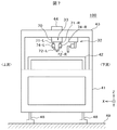
次に、図7によって、本発明のデュアルPH方式のダイボンダの外観を説明する。図7は、本発明のデュアルPH方式のダイボンダの一実施例の外観を説明するための概略図である。なお、実施例2においても、実施例1の図2乃至図4で説明した構成は同一であり、適宜図5及び図6で説明した接着剤塗布方法を適用する。
図7のダイボンダ100は、下架台41の上に搬送レーン42と上架台43が固定され、下架台41はアジャスタ脚48で床49上に水平に設置される。搬送レーン42は、フレームフィーダ22によって基板Pを上流から下流に搬送するための搬送路である。
図7に示すように、接着剤塗布をするためのボンディングヘッド部32は、ダイボンダ100の上架台43の上部のビームに固定される。このため、ビームを介して、それぞれのヘッド部の振動が他のヘッド部に伝わり易い。
本発明のダイボンダでは、接着剤塗布を2か所で、非同期に行うために、ボンディングヘッド部32のプリフォーム部(PH)33は、2つのPHを備えている。PHが2つになり、X軸、Y軸、及びZ軸に互いに独立に駆動することで、接着剤塗布動作による装置振動が拡大され、ダイボンド精度の悪化が懸念される。このため、装置振動対策が必要である。
Next, the external appearance of the dual PH type die bonder of the present invention will be described with reference to FIG. FIG. 7 is a schematic view for explaining the appearance of an embodiment of the dual PH type die bonder of the present invention. In Example 2, the configuration described in FIGS. 2 to 4 of Example 1 is the same, and the adhesive application method described in FIGS. 5 and 6 is applied as appropriate.
In the
As shown in FIG. 7, the
In the die bonder of the present invention, the preform part (PH) 33 of the
図8〜図10によって、本発明の接着剤塗布方法及びダイボンディング方法及びダイボンダにおける装置振動対策を説明する。図8〜図10は、本発明の接着剤塗布方法の一実施例を説明するための図である。
本発明の実施例2のポイントは、左右のプリフォーム部33−L及び33−Rが接着剤を塗布する動作において、XY(水平)方向の動作を一方のヘッドの移動に対して、他方のヘッドを同時に逆方向に移動させる。これによって、接着剤塗布動作時の加振力を相殺させ、振動の低減を行うものである。即ち、装置の高速化を目的として搭載したユニット(デュアルPH方式)を、振動低減用機構部としても使用するものである。
With reference to FIGS. 8 to 10, the adhesive application method, die bonding method, and device vibration countermeasure of the die bonder according to the present invention will be described. 8-10 is a figure for demonstrating one Example of the adhesive agent coating method of this invention.
The point of the second embodiment of the present invention is that in the operation in which the left and right preform parts 33-L and 33-R apply the adhesive, the operation in the XY (horizontal) direction is changed with respect to the movement of one head. Move the heads in the opposite direction simultaneously. As a result, the vibration force is reduced by offsetting the excitation force during the adhesive application operation. That is, a unit (dual PH system) mounted for the purpose of speeding up the apparatus is also used as a vibration reduction mechanism.
例えば、図8において、右側のプリフォーム部33−R(シリンジ部72−R)が塗布エリアPP01とPP02に接着剤を塗布し、左側のプリフォーム部33−L(シリンジ部72−L)が塗布エリアPP03とPP04に接着剤を塗布するような役割分担とする。このとき、塗布動作を全て反対方向に且つ同時に行う。即ち、まず、2つのプリフォーム部のシリンジ部がそれぞれ塗布するために予め割り当てられた塗布エリアの上方に移動する。その後、X軸駆動部76−Rと76−Lの駆動方向及び駆動距離は、X軸方向に対して逆方向に移動する。同様に、Y軸駆動部75−Rと75−Lの駆動方向及び駆動距離は、Y軸方向に対して逆方向に移動する。従って、プリフォーム部33−R及び33−Lは、Z軸駆動部74−R及び74−Lをそれぞれ駆動して、ノズルを基板Pの塗布エリアの塗布高さまで下降させる。下降後、所定の描画経路となるように、X軸駆動部及びY軸駆動部を駆動して、XY平面上に接着剤塗布を行う。また、X軸駆動部76−Rと76−L、Y軸駆動部75−Rと75−L、及びZ軸駆動部74−Rと74−Lは、それぞれ駆動の開始と駆動の終了が同時である。
例えば、塗布エリアPP01とPP02には、矢印DR方向に塗布し、塗布エリアPP03とPP04には、矢印DL方向に塗布する。この時、塗布のための両者のXY平面上の移動距離は等しい(等距離移動する)。
即ち、プリフォーム部33−Rが塗布エリアPP0の描画開始点d11から描画終了点d12まで接着剤塗布すると同時に、プリフォーム部33−Lは塗布エリアPP3の描画開始点d31から描画終了点d32まで接着剤を塗布する。
塗布エリアPP02とPP04に接着剤を塗布する場合も同様に、プリフォーム部33−Rとプリフォーム部33−LのXY方向への塗布方向を、全て反対且つ同時に実行する。即ち、X軸駆動機構76−Rと76−Lの駆動方向を全て反対且つ同時に実行し、Y軸駆動機構75−Rと75−Lの駆動方向を全て反対且つ同時に実行する(カウンタ動作)。
なお、塗布動作終了後の移動動作は、この限りではない。
For example, in FIG. 8, the right preform part 33-R (syringe part 72-R) applies adhesive to the application areas PP01 and PP02, and the left preform part 33-L (syringe part 72-L) The role is shared such that the adhesive is applied to the application areas PP03 and PP04. At this time, all coating operations are performed simultaneously in the opposite direction. That is, first, the syringe parts of the two preform parts move above the application area assigned in advance for application. Thereafter, the drive direction and drive distance of the X-axis drive units 76-R and 76-L move in the opposite direction to the X-axis direction. Similarly, the drive direction and drive distance of the Y-axis drive units 75-R and 75-L move in the opposite direction to the Y-axis direction. Accordingly, the preform parts 33-R and 33-L drive the Z-axis drive parts 74-R and 74-L, respectively, to lower the nozzle to the coating height of the coating area of the substrate P. After descending, the X-axis drive unit and the Y-axis drive unit are driven so as to form a predetermined drawing path, and the adhesive is applied on the XY plane. The X-axis drive units 76-R and 76-L, the Y-axis drive units 75-R and 75-L, and the Z-axis drive units 74-R and 74-L respectively start and end simultaneously. It is.
For example, the application areas PP01 and PP02 are applied in the arrow DR direction, and the application areas PP03 and PP04 are applied in the arrow DL direction. At this time, the movement distance on both XY planes for application is equal (moves equidistantly).
That is, the preform portion 33-R applies adhesive from the drawing start point d11 of the application area PP0 to the drawing end point d12, and at the same time, the preform portion 33-L extends from the drawing start point d31 of the application area PP3 to the drawing end point d32. Apply adhesive.
Similarly, when the adhesive is applied to the application areas PP02 and PP04, the application directions in the XY directions of the preform portion 33-R and the preform portion 33-L are all oppositely and simultaneously executed. That is, the drive directions of the X-axis drive mechanisms 76-R and 76-L are all executed oppositely and simultaneously, and the drive directions of the Y-axis drive mechanisms 75-R and 75-L are executed oppositely and simultaneously (counter operation).
In addition, the movement operation | movement after completion | finish of application | coating operation | movement is not this limitation.
また、図9に示すように、右側のプリフォーム部33−R(シリンジ部72−R)が塗布エリアPP11〜PP13に接着剤を塗布し、左側のプリフォーム部33−L(シリンジ部72−L)が塗布エリアPP14とPP15に接着剤を塗布するような役割分担とする。
即ち、図9においても、塗布動作を全て反対且つ同時に行う。塗布エリアPP11〜PP12及びPP14〜PP15の動作は、図8で説明した動作と同一である。
例えば、図9において、右側のプリフォーム部33−Rが塗布エリアPP11に接着剤を塗布する場合には、左側のプリフォーム部33−Lが塗布エリアPP14に同時に且つ逆方向に接着剤を塗布する。次に、右側のプリフォーム部33−Rが塗布エリアPP12に接着剤を塗布する場合には、左側のプリフォーム部33−Lが塗布エリアPP15に同時に且つ逆方向に接着剤を塗布する(カウンタ動作)。
Further, as shown in FIG. 9, the right preform part 33-R (syringe part 72-R) applies adhesive to the application areas PP11 to PP13, and the left preform part 33-L (syringe part 72-R). L) divides roles such that the adhesive is applied to the application areas PP14 and PP15.
That is, also in FIG. 9, all coating operations are performed in the opposite and simultaneous manner. The operations of the application areas PP11 to PP12 and PP14 to PP15 are the same as those described with reference to FIG.
For example, in FIG. 9, when the right preform part 33-R applies adhesive to the application area PP11, the left preform part 33-L applies adhesive to the application area PP14 simultaneously and in the opposite direction. To do. Next, when the right preform part 33-R applies the adhesive to the application area PP12, the left preform part 33-L applies the adhesive to the application area PP15 simultaneously and in the opposite direction (counter). Operation).
次に、図10に示すように、右側のプリフォーム部33−R(シリンジ部72−R)が塗布エリアPP21〜PP23に接着剤を塗布し、左側のプリフォーム部33−L(シリンジ部72−L)が塗布エリアPP24〜PP26に接着剤を塗布するような役割分担とする。このときにおいても、塗布動作を全て反対且つ同時に行う。
即ち、図10においても、塗布動作を全て反対且つ同時に行う。塗布エリアPP21〜PP22及びPP24〜PP25の動作は、図8で説明した動作と同一である。
例えば、図10において、右側のプリフォーム部33−R(図10に示すシリンジ部72−R)が塗布エリアPP21に接着剤を塗布する場合には、左側のプリフォーム部33−L(図10に示すシリンジ部72−L)が塗布エリアPP24に同時に且つ逆方向に接着剤を塗布する。その後、同様に2つのヘッドが塗布エリアPP22と塗布エリアPP25を接着剤塗布する。即ち、右側のプリフォーム部33−Rが塗布エリアPP22に接着剤を塗布する場合には、左側のプリフォーム部33−Lが塗布エリアPP25に同時に且つ逆方向に接着剤を塗布する(カウンタ動作)。
Next, as shown in FIG. 10, the right preform part 33-R (syringe part 72-R) applies adhesive to the application areas PP21 to PP23, and the left preform part 33-L (syringe part 72). -L) assigns roles such that the adhesive is applied to the application areas PP24 to PP26. Even at this time, all coating operations are performed in the opposite and simultaneous manner.
That is, also in FIG. 10, all coating operations are performed in the opposite and simultaneous manner. The operation of the application areas PP21 to PP22 and PP24 to PP25 is the same as the operation described in FIG.
For example, in FIG. 10, when the right preform part 33-R (syringe part 72-R shown in FIG. 10) applies an adhesive to the application area PP21, the left preform part 33-L (FIG. 10). Syringe part 72-L) applies an adhesive to the application area PP24 simultaneously and in the opposite direction. Thereafter, similarly, the two heads apply the coating area PP22 and the coating area PP25 with an adhesive. That is, when the right preform part 33-R applies the adhesive to the application area PP22, the left preform part 33-L applies the adhesive to the application area PP25 simultaneously and in the opposite direction (counter operation). ).
図8と図9は、基板P上に配置された塗布エリアにおいて、その1列分について接着剤を塗布する場合の実施例である。また、図10は、配置された塗布エリアの基板P上に配置された塗布エリアにおいて、その2列分について接着剤を塗布する場合の実施例である。
いずれにしても、本発明のデュアルPH方式のダイボンダにおいて、左右のプリフォーム部のX軸駆動機構とY軸駆動機構を、それぞれ互いに逆方向に動作(カウンタ動作)させることができ、その結果、装置に与えられる振動を低減することができる。
FIG. 8 and FIG. 9 are examples in the case where the adhesive is applied to one row in the application area arranged on the substrate P. FIG. FIG. 10 shows an example in which the adhesive is applied to the two rows in the application area arranged on the substrate P of the arranged application area.
In any case, in the dual PH method die bonder of the present invention, the X-axis drive mechanism and the Y-axis drive mechanism of the left and right preform parts can be operated in opposite directions (counter operation), respectively. The vibration applied to the device can be reduced.
次に、対応する塗布エリアが、他方にない場合について、本発明のデュアルPH方式のダイボンダにおける接着剤塗布方法について説明する。
図9において、右側のプリフォーム部33−Rが塗布エリアPP13に接着剤を塗布する場合には、左側のプリフォーム部33−Lが塗布する塗布エリアがない。そこで、本発明は、仮想の塗布エリアPP16を設けた。なお、仮想の塗布エリアの設定は、例えば、2つのプリフォーム部に所定の領域を予め役割分担するときに行う。そして、右側のプリフォーム部33−Rが塗布エリアPP13に接着剤を塗布する場合には、左側のプリフォーム部33−Lは、仮想のPP16に同時に且つ逆方向に接着剤を塗布する動作を行う(ダミーカウンタ動作)。即ち、仮想の塗布エリアの場合においても、プリフォーム部33−Rとプリフォーム部33−LのXY方向への塗布方向を、全て反対且つ同時に実行する。即ち、X軸駆動部76−Rと76−Lの駆動方向及び駆動距離は、X軸方向に対して逆方向に移動する。同様に、Y軸駆動部75−Rと75−Lの駆動方向及び駆動距離は、Y軸方向に対して逆方向に移動する。また、X軸駆動部76−Rと76−L、及びY軸駆動部75−Rと75−Lは、それぞれ駆動の開始と駆動の終了が同時である。
例えば、X軸駆動機構76−Rと76−Lの駆動方向を全て反対且つ同時に実行し、Y軸駆動機構75−Rと75−Lの駆動方向を全て反対且つ同時に実行する(ダミーカウンタ動作)。ただし、仮想の塗布エリアの塗布動作(ダミーカウンタ動作)においては、Z軸駆動機構74−Lは動作せず(基板Pの上方にあり、下降しない)、かつ、シリンジ部72−Lから接着剤を吐出しない。また、塗布動作終了後の移動動作は、この限りではない。しかしこの時、塗布するしないにかかわらず、両者のXY平面上の移動距離は等しい。
Next, the adhesive coating method in the dual PH die bonder of the present invention will be described in the case where there is no corresponding coating area on the other side.
In FIG. 9, when the right preform part 33-R applies an adhesive to the application area PP13, there is no application area to which the left preform part 33-L applies. Therefore, in the present invention, a virtual application area PP16 is provided. The virtual application area is set when, for example, a predetermined area is assigned to two preform parts in advance. When the right preform part 33-R applies the adhesive to the application area PP13, the left preform part 33-L performs the operation of applying the adhesive to the virtual PP 16 simultaneously and in the opposite direction. Perform (dummy counter operation). That is, even in the case of the virtual application area, the application directions in the XY directions of the preform portion 33-R and the preform portion 33-L are all executed oppositely and simultaneously. That is, the drive direction and drive distance of the X-axis drive units 76-R and 76-L move in the opposite direction to the X-axis direction. Similarly, the drive direction and drive distance of the Y-axis drive units 75-R and 75-L move in the opposite direction to the Y-axis direction. In addition, the X-axis drive units 76-R and 76-L and the Y-axis drive units 75-R and 75-L start and finish driving simultaneously, respectively.
For example, the drive directions of the X-axis drive mechanisms 76-R and 76-L are all executed oppositely and simultaneously, and the drive directions of the Y-axis drive mechanisms 75-R and 75-L are executed oppositely and simultaneously (dummy counter operation). . However, in the application operation (dummy counter operation) of the virtual application area, the Z-axis drive mechanism 74-L does not operate (is above the substrate P and does not descend), and the adhesive from the syringe unit 72-L. Do not discharge. Further, the movement operation after the application operation is not limited to this. However, at this time, the movement distance on both XY planes is the same regardless of whether or not coating is performed.
さらに、図9の実施例では、仮想の塗布エリアPP16を設定したが、接着剤塗布の未着工または塗布済みの(例えば、塗布エリアPP14、PP15)塗布エリア、等の実際の塗布エリアでプリフォーム部33−LのX軸駆動機構76−L及びY軸駆動機構75−Lを駆動させても良い。これによれば、ダミーカウンタ動作が、基板P上の塗布エリアの配置によっては基板P(または搬送レーンのプリフォームエリア)上の塗布可能な領域を外れてしまう場合にも、プリフォーム部33−LのX軸駆動機構76−L及びY軸駆動機構75−Lが清浄に動作可能である。
また、ここで説明したダミーカウンタ動作は、図8または図9に示した塗布エリア1列ごとに2つのヘッド(プリフォーム部)を割り当てる場合だけでなく、例えば、塗布エリア2列ごとに2つのヘッド(プリフォーム部)を割り当てる場合にも適用可能であり、他の割り当て方法においても適用可能であることは勿論のことである。
Further, in the embodiment of FIG. 9, the virtual application area PP16 is set, but the preform is formed in an actual application area such as an unapplied adhesive application or an application area (for example, application area PP14, PP15). The X-axis drive mechanism 76-L and the Y-axis drive mechanism 75-L of the unit 33-L may be driven. According to this, even when the dummy counter operation deviates from the coatable area on the substrate P (or the preform area of the transfer lane) depending on the arrangement of the coating area on the substrate P, the preform portion 33- The X-axis drive mechanism 76-L and the Y-axis drive mechanism 75-L of L can operate cleanly.
In addition, the dummy counter operation described here is not limited to the case where two heads (preform parts) are assigned to each application area row shown in FIG. 8 or FIG. Needless to say, the present invention can be applied to the case of assigning a head (preform portion), and can be applied to other assignment methods.
また、図10において、塗布エリアPP23が不良タブである場合には、接着剤塗布を不良タブに実行すると、不良タブの塗布エリア上にマークした不良の印が見えなくなってしまうため、塗布エリアPP23に接着剤塗布をしない。
従って、プリフォーム部33−R(図10では、シリンジ部72−R2)は、プリフォーム部33−L(図10では、シリンジ部72−L2)の接着剤塗布動作(矢印DL2)に同期して、不良タブである塗布エリアPP23上でダミーカウンタ動作(矢印DR2)を行う(ダミーカウンタ動作)。即ち、X軸駆動部76−Rと76−Lの駆動方向及び駆動距離は、X軸方向に対して逆方向に移動する。同様に、Y軸駆動部75−Rと75−Lの駆動方向及び駆動距離は、Y軸方向に対して逆方向に移動する。また、X軸駆動部76−Rと76−L、及びY軸駆動部75−Rと75−Lは、それぞれ駆動の開始と駆動の終了が同時である。
例えば、X軸駆動機構76−Rと76−Lの駆動方向を全て反対に且つ同時に実行し、Y軸駆動機構75−Rと75−Lの駆動方向を全て反対に且つ同時に実行する(ダミーカウンタ動作)。ただし、不良タブである塗布エリアにおいては、Z軸駆動機構74−Lは動作せず(基板Pの上方にある)、かつ、シリンジ部72−R2から接着剤を吐出しない。また、塗布動作終了後の移動動作は、この限りではない。しかしこの時、塗布するしないにかかわらず、両者のXY平面上の移動距離は等しい。
なお、プリフォーム部33−R及びプリフォーム部33−Lが塗布しようとする塗布エリアがどちらも不良タブであった場合には、これらの塗布エリアでの塗布動作をせず、次の塗布エリアに移動する。
In FIG. 10, when the application area PP23 is a defective tab, if the adhesive application is performed on the defective tab, the mark of the defect marked on the application area of the defective tab becomes invisible. Do not apply adhesive.
Accordingly, the preform part 33-R (syringe part 72-R2 in FIG. 10) is synchronized with the adhesive application operation (arrow DL2) of the preform part 33-L (syringe part 72-L2 in FIG. 10). Then, a dummy counter operation (arrow DR2) is performed on the application area PP23 which is a defective tab (dummy counter operation). That is, the drive direction and drive distance of the X-axis drive units 76-R and 76-L move in the opposite direction to the X-axis direction. Similarly, the drive direction and drive distance of the Y-axis drive units 75-R and 75-L move in the opposite direction to the Y-axis direction. In addition, the X-axis drive units 76-R and 76-L and the Y-axis drive units 75-R and 75-L start and finish driving simultaneously, respectively.
For example, the drive directions of the X-axis drive mechanisms 76-R and 76-L are all executed oppositely and simultaneously, and the drive directions of the Y-axis drive mechanisms 75-R and 75-L are executed oppositely and simultaneously (dummy counter). Operation). However, in the application area which is a defective tab, the Z-axis drive mechanism 74-L does not operate (above the substrate P) and does not discharge the adhesive from the syringe part 72-R2. Further, the movement operation after the application operation is not limited to this. However, at this time, the movement distance on both XY planes is the same regardless of whether or not coating is performed.
If both of the application areas to be applied by the preform portion 33-R and the preform portion 33-L are defective tabs, the application operation in these application areas is not performed, and the next application area is not performed. Move to.
実施例2によれば、デュアルPH方式のダイボンダにおいて、一方のプリフォーム部を駆動する場合に発生する振動を、他方のプリフォーム部を駆動させて相殺させることができ、PH(プリフォーム部)の動作に起因する装置の振動を小さくすることが可能な接着剤塗布方法及びダイボンディング方法及びダイボンダを実現することができる。さらに、別の効果として、振動が低減できるため、ダイボンド精度が向上する。また、振動が低減できるため、振動の影響を考えずにさらに高速にプリフォーム部を駆動させることができ、高速運転可能な接着剤塗布方法及びダイボンディング方法及びダイボンダを実現することができる。 According to the second embodiment, in the dual PH type die bonder, vibration generated when one preform portion is driven can be canceled by driving the other preform portion, and PH (preform portion) Thus, it is possible to realize an adhesive coating method, a die bonding method, and a die bonder that can reduce the vibration of the apparatus due to the above operation. Furthermore, as another effect, since vibration can be reduced, die bonding accuracy is improved. Further, since vibration can be reduced, the preform portion can be driven at a higher speed without considering the influence of vibration, and an adhesive coating method, a die bonding method, and a die bonder that can be operated at high speed can be realized.
以上、本発明を実施例によって詳細に説明したが、上述の説明に基づいて当業者にとって種々の代替例、修正又は変形が可能であり、本発明はその趣旨を逸脱しない範囲で前述の種々の代替例、修正又は変形を包含するものである。また、本発明は、上述の実施例に限定されるわけではなく、本発明が属する技術分野において、通常の知識を有する者であれば、本発明の思想と精神に基づいて、本発明を修正若しくは変更できる発明が含まれることは勿論である。 Although the present invention has been described in detail with reference to the embodiments, various alternatives, modifications, and variations can be made by those skilled in the art based on the above description. The present invention is not limited to the above-described various modifications. It encompasses alternatives, modifications or variations. Further, the present invention is not limited to the above-described embodiments, and the present invention can be modified based on the spirit and spirit of the present invention as long as the person has ordinary knowledge in the technical field to which the present invention belongs. Of course, the invention which can be changed is included.
1:ウェハ供給部、 2:ワーク供給・搬送部、 3:ダイボンディング部、 4、4−1、4−2:ダイ、 5:ウェハ、 6:コレット、 7、7−1、7−2:描画パターン、 10:制御部、 11:ウェハカセットリフタ、 12:ピックアップ装置、 21:スタックローダ、 22:フレームフィーダ、 23:アンローダ、 32:ボンディングヘッド部、 33、33−R、33−L:プリフォーム部、 41:下架台、 42:搬送レーン、 43:上架台、 48:アジャスタ脚、 49:床、 70:塗布ユニット、 71−R、71−L:ビーム、 72、72−R、72−L:シリンジ部、 73、73−R、73−L:ノズル、 73−1:吐出口、 74−R、74−L:Z軸駆動機構、 75−R、75−L:Y軸駆動機構、 76−R、76−L:X軸駆動機構、 77:シリンジ、 78:シリンジホルダ、 79−1:斜め開口部、 79−2:垂直開口部、 100:ダイボンダ、 P:基板、 PP:塗布エリア。
1: Wafer supply unit, 2: Workpiece supply / conveyance unit, 3: Die bonding unit, 4, 4-1, 4-2: Die, 5: Wafer, 6: Collet, 7, 7-1, 7-2: Drawing pattern 10: Control unit 11: Wafer cassette lifter 12: Pickup device 21: Stack loader 22: Frame feeder 23: Unloader 32:
Claims (6)
被搭載対象物を搬送するワーク供給・搬送部と、
前記被搭載対象物の塗布エリアにペースト状の接着剤を塗布するためのプリフォーム部と、
前記接着剤を塗布された前記被搭載対象物に前記ダイを搭載するためのボンディングヘッド部と、
前記ダイを前記被搭載対象物にボンディングするダイボンディング部と、
前記ウェハ供給部と前記ワーク供給・搬送部と前記プリフォーム部と前記ボンディングヘッド部と前記ダイボンディング部とを制御する制御部と、
を備え、
前記プリフォーム部は、第1の塗布エリアと第2の塗布エリアに分けられた前記塗布エリアのうち前記第1の塗布エリアに前記接着剤を塗布する第1のプリフォーム部、及び、前記第2の塗布エリアに前記接着剤を塗布する第2のプリフォーム部を備え、前記第1のプリフォーム部がX軸方向及びY軸方向に移動して接着剤塗布を行う場合に、前記第2のプリフォーム部は、前記第1のプリフォーム部が移動するX軸方向及びY軸方向に対して同時に逆方向に等距離移動して接着剤塗布を行い、
前記第2のプリフォーム部は、前記第1のプリフォーム部が前記第1の塗布エリアに前記接着剤を塗布するためにX軸方向及びY軸方向に移動する場合に、前記第2のプリフォーム部が前記接着剤を塗布するための第2の塗布エリアが無い場合には、予め定めた仮想の塗布エリア上に移動し、前記第1のプリフォーム部が移動するX軸方向及びY軸方向に対して同時に逆方向に等距離移動し、且つ、前記接着剤の吐出をしないことを特徴とするダイボンダ。 A wafer supply unit for supplying dies from the wafer;
A workpiece supply / conveyance section that conveys the object to be mounted;
And the preform portion for applying a pasty adhesive coating areas of the object to be mounted object,
A bonding head for mounting the die on said mountable object the adhesive is applied,
A die bonding part for bonding the die to the mounted object;
A control unit for controlling said wafer supply section and the workpiece supplying and conveying section and the preform part and the bonding head and the die bonding portion,
With
The preform part includes a first preform part that applies the adhesive to the first application area among the application areas divided into a first application area and a second application area; and A second preform part that applies the adhesive to two application areas, and the first preform part moves in the X-axis direction and the Y-axis direction to perform adhesive application. preform part, have the rows adhesive application by the same distance moved in the opposite direction at the same time with respect to the X-axis direction and the Y-axis direction first preform portion moves in,
The second preform portion is configured to move the second preform portion when the first preform portion moves in the X-axis direction and the Y-axis direction in order to apply the adhesive to the first application area. When there is no second application area for applying the adhesive to the reforming part, it moves over a predetermined virtual application area, and the X-axis direction and the Y-axis in which the first preform part moves A die bonder characterized by moving at the same distance in the opposite direction simultaneously with respect to the direction and not discharging the adhesive .
前記第1の塗布エリアまたは前記第2の塗布エリアのどちらかが不良タブである場合には、当該不良タブの塗布エリアを塗布する前記第1のプリフォーム部または前記第2のプリフォーム部は、他方の前記第2のプリフォーム部または前記第1のプリフォーム部が移動するX軸方向及びY軸方向に対して同時に逆方向に等距離移動し、且つ、前記接着剤の吐出をしないことを特徴とするダイボンダ。 The die bonder according to claim 1 , wherein
When either the first application area or the second application area is a defective tab, the first preform part or the second preform part for applying the application area of the defective tab is The other second preform part or the first preform part moves at the same distance in the opposite direction to the X axis direction and the Y axis direction in which the second preform part moves, and does not discharge the adhesive. Die bonder characterized by.
前記第1のプリフォーム部が前記第1の塗布エリアに前記接着剤を塗布する際に前記接着剤を吐出するための第1のディスペンサ装置と、前記第2のプリフォーム部が前記第2の塗布エリアに前記接着剤を塗布する際に前記接着剤を吐出するための第2のディスペンサ装置と、を備え、前記第1のディスペンサ装置及び前記第2のディスペンサ装置はそれぞれ独立にX方向及びY方向に駆動するX軸駆動機構及びY軸駆動機構を備えたことを特徴とするダイボンダ。 The die bonder according to claim 1 or 2 ,
A first dispenser device for discharging the adhesive when the first preform portion applies the adhesive to the first application area, and the second preform portion is the second dispenser. A second dispenser device for discharging the adhesive when the adhesive is applied to the application area, wherein the first dispenser device and the second dispenser device are respectively independently in the X direction and the Y direction. A die bonder comprising an X-axis drive mechanism and a Y-axis drive mechanism for driving in a direction.
前記第1のディスペンサ装置及び前記第2のディスペンサ装置は、前記接着剤が入っているシリンジと、前記シリンジ内の前記接着剤を垂直下方に吐出するためのノズルと、前記シリンジを斜めに装着可能で、前記シリンジ内の前記接着剤を垂直下方に吐出するために垂直下方に前記ノズルを取付けたシリンジホルダからそれぞれ成ることを特徴とするダイボンダ。 The die bonder according to claim 3 ,
The first dispenser device and the second dispenser device can be mounted obliquely on a syringe containing the adhesive, a nozzle for discharging the adhesive in the syringe vertically downward, and the syringe. The die bonder is characterized by comprising a syringe holder to which the nozzle is attached vertically downward in order to discharge the adhesive in the syringe vertically downward.
前記第1の塗布エリアに前記接着剤を塗布するために前記第1のプリフォーム部がX軸方向及びY軸方向に移動する場合に、前記第2のプリフォーム部が前記接着剤を塗布するための前記第2の塗布エリアが無い場合には、前記第2のプリフォーム部は、予め定めた仮想の塗布エリア上に移動し、前記第1のプリフォーム部が移動するX軸方向及びY軸方向に対して同時に逆方向に等距離移動し、且つ、前記接着剤の吐出をしないことを特徴とする接着剤塗布方法。 The adhesive is applied to the first application area among the application areas of the object to be mounted on which a paste-like adhesive is applied in order to mount the die, which is divided into a first application area and a second application area. When the first preform portion is moved in the X-axis direction and the Y-axis direction to apply the adhesive to apply the adhesive, the second preform is applied to apply the adhesive to the second application area. reform section have rows application of the adhesive by the same distance moved in the opposite direction at the same time with respect to the X-axis direction and the Y-axis direction of the first preform portion moves,
When the first preform portion moves in the X-axis direction and the Y-axis direction in order to apply the adhesive to the first application area, the second preform portion applies the adhesive. When there is no second application area for the second preform part, the second preform part moves onto a predetermined virtual application area, and the first preform part moves in the X-axis direction and the Y direction. A method of applying an adhesive , wherein the adhesive is moved at an equal distance in the opposite direction simultaneously with respect to the axial direction, and the adhesive is not discharged .
前記第1の塗布エリアまたは前記第2の塗布エリアのどちらかが不良タブである場合には、当該不良タブの塗布エリアを塗布する前記第1のプリフォーム部または前記第2のプリフォーム部は、他方の前記第1のプリフォーム部または前記第2のプリフォーム部が移動するX軸方向及びY軸方向に対して同時に逆方向に等距離移動し、且つ、前記接着剤の吐出をしないことを特徴とする接着剤塗布方法。 In the adhesive application method according to claim 5 ,
When either the first application area or the second application area is a defective tab, the first preform part or the second preform part for applying the application area of the defective tab is The other first preform part or the second preform part is simultaneously moved at the same distance in the opposite direction to the X axis direction and the Y axis direction in which the second preform part moves, and the adhesive is not discharged. An adhesive coating method characterized by the above.
Priority Applications (4)
| Application Number | Priority Date | Filing Date | Title |
|---|---|---|---|
| JP2013209326A JP6276552B2 (en) | 2013-10-04 | 2013-10-04 | Die bonder and adhesive coating method |
| TW103130095A TWI532109B (en) | 2013-10-04 | 2014-09-01 | Grain Adhesive and Adhesive Coating Method |
| CN201410453347.1A CN104517861B (en) | 2013-10-04 | 2014-09-05 | Chip attachment machine and bonding agent painting method |
| KR1020140118651A KR101664555B1 (en) | 2013-10-04 | 2014-09-05 | Die bonder and adhesive application method |
Applications Claiming Priority (1)
| Application Number | Priority Date | Filing Date | Title |
|---|---|---|---|
| JP2013209326A JP6276552B2 (en) | 2013-10-04 | 2013-10-04 | Die bonder and adhesive coating method |
Publications (2)
| Publication Number | Publication Date |
|---|---|
| JP2015076409A JP2015076409A (en) | 2015-04-20 |
| JP6276552B2 true JP6276552B2 (en) | 2018-02-07 |
Family
ID=52792983
Family Applications (1)
| Application Number | Title | Priority Date | Filing Date |
|---|---|---|---|
| JP2013209326A Active JP6276552B2 (en) | 2013-10-04 | 2013-10-04 | Die bonder and adhesive coating method |
Country Status (4)
| Country | Link |
|---|---|
| JP (1) | JP6276552B2 (en) |
| KR (1) | KR101664555B1 (en) |
| CN (1) | CN104517861B (en) |
| TW (1) | TWI532109B (en) |
Cited By (1)
| Publication number | Priority date | Publication date | Assignee | Title |
|---|---|---|---|---|
| US20220122939A1 (en) * | 2020-10-15 | 2022-04-21 | Gallant Micro. Machining Co., Ltd. | Producing apparatus and pre-bonding device |
Families Citing this family (5)
| Publication number | Priority date | Publication date | Assignee | Title |
|---|---|---|---|---|
| EP3391974B1 (en) * | 2015-12-15 | 2022-06-01 | Senju Metal Industry Co., Ltd. | Fluid discharge device and method for discharging fluid |
| CN110413087B (en) * | 2019-08-13 | 2022-06-07 | 徐州工业职业技术学院 | Computer motherboard chip heat dissipation silica gel pastes dress device |
| CN114388391A (en) * | 2020-10-22 | 2022-04-22 | 均华精密工业股份有限公司 | Production facility and pre-bonding device |
| CN117912982B (en) * | 2022-10-12 | 2024-09-24 | 湖南奥创普科技有限公司 | Single-channel chip mounter and chip mount method |
| CN117101966B (en) * | 2023-10-18 | 2023-12-26 | 启东市旭能电子科技有限公司 | Lithium battery charger chip heat conduction silicone grease smearing machine |
Family Cites Families (12)
| Publication number | Priority date | Publication date | Assignee | Title |
|---|---|---|---|---|
| JPS6397259A (en) * | 1986-10-14 | 1988-04-27 | Shinkawa Ltd | Paste discharger |
| JP2671005B2 (en) * | 1988-04-13 | 1997-10-29 | 株式会社 新川 | Dispenser device |
| JP3609359B2 (en) | 2001-08-21 | 2005-01-12 | 株式会社 日立インダストリイズ | Paste application machine and paste application method |
| JP4481576B2 (en) * | 2003-02-28 | 2010-06-16 | 芝浦メカトロニクス株式会社 | Paste applicator |
| JP4489524B2 (en) * | 2004-07-23 | 2010-06-23 | 株式会社ルネサステクノロジ | Semiconductor device manufacturing method and paste coating apparatus |
| CH697827B1 (en) * | 2005-07-25 | 2009-02-27 | Oerlikon Assembly Equipment Ag | Means for applying adhesive to a substrate. |
| TW200914146A (en) * | 2007-02-06 | 2009-04-01 | Shibaura Mechatronics Corp | Paste applicator and paste application method |
| JP4945351B2 (en) | 2007-07-18 | 2012-06-06 | ルネサスエレクトロニクス株式会社 | Manufacturing method of semiconductor device |
| KR100899674B1 (en) * | 2008-01-22 | 2009-05-28 | 주식회사 탑 엔지니어링 | Displacement sensor capable of syringe mounting and dispenser with the same |
| JP5368783B2 (en) * | 2008-12-24 | 2013-12-18 | 東レエンジニアリング株式会社 | Coating method and coating apparatus |
| JP5789389B2 (en) * | 2011-03-23 | 2015-10-07 | ファスフォードテクノロジ株式会社 | Die bonder and semiconductor manufacturing method |
| JP2013039528A (en) * | 2011-08-17 | 2013-02-28 | Jcm:Kk | Coating apparatus |
-
2013
- 2013-10-04 JP JP2013209326A patent/JP6276552B2/en active Active
-
2014
- 2014-09-01 TW TW103130095A patent/TWI532109B/en active
- 2014-09-05 KR KR1020140118651A patent/KR101664555B1/en active Active
- 2014-09-05 CN CN201410453347.1A patent/CN104517861B/en active Active
Cited By (2)
| Publication number | Priority date | Publication date | Assignee | Title |
|---|---|---|---|---|
| US20220122939A1 (en) * | 2020-10-15 | 2022-04-21 | Gallant Micro. Machining Co., Ltd. | Producing apparatus and pre-bonding device |
| US11784158B2 (en) * | 2020-10-15 | 2023-10-10 | Gallant Micro. Machining Co., Ltd. | Producing apparatus |
Also Published As
| Publication number | Publication date |
|---|---|
| TW201526128A (en) | 2015-07-01 |
| TWI532109B (en) | 2016-05-01 |
| KR101664555B1 (en) | 2016-10-11 |
| CN104517861A (en) | 2015-04-15 |
| KR20150040208A (en) | 2015-04-14 |
| CN104517861B (en) | 2017-08-25 |
| JP2015076409A (en) | 2015-04-20 |
Similar Documents
| Publication | Publication Date | Title |
|---|---|---|
| JP6276552B2 (en) | Die bonder and adhesive coating method | |
| JP5745386B2 (en) | Die bonder with dual head dispenser | |
| CN103372519A (en) | Paste applying apparatus, paste applying method, and die bonder | |
| US20130068824A1 (en) | Die Bonder and Bonding Method | |
| JP5894738B2 (en) | Die bonder and semiconductor manufacturing method | |
| TW201606906A (en) | Die bonder and bonding method | |
| JP2019160948A (en) | Die bonding device and manufacturing method of semiconductor device | |
| KR20150039688A (en) | Electrode forming apparatus, electrode forming system, and electrode forming method | |
| JP7018338B2 (en) | Manufacturing method of die bonding equipment and semiconductor equipment | |
| JP4891185B2 (en) | Viscous fluid application device | |
| TW200416910A (en) | Board conveyance apparatus, component mounting apparatus, and board conveyance method in component mounting | |
| CN111656505B (en) | Soldering tool for soldering machine, soldering machine for soldering semiconductor element and related method | |
| JP3674587B2 (en) | Electronic component mounting method | |
| KR101471900B1 (en) | Substrate processing apparatus | |
| KR101913230B1 (en) | LED Chip Packages With Micro LED Chips Thereon and Manufacturing method thereof | |
| JP5789389B2 (en) | Die bonder and semiconductor manufacturing method | |
| CN107615909A (en) | Optimum procedure and installation exercise machine | |
| US10729048B2 (en) | Optimization program and mounting work system | |
| KR101690725B1 (en) | Method and apparatus for optimizing components mounting of mounter | |
| JP2012199442A (en) | Die bonder and semiconductor manufacturing method | |
| JP7837451B1 (en) | Coating apparatus, coating method, electronic component mounting apparatus, and electronic component mounting method | |
| JP7812747B2 (en) | Component mounting device and component mounting method | |
| JP2024111761A (en) | Semiconductor manufacturing apparatus and method for manufacturing semiconductor device | |
| KR20240112193A (en) | Bonding apparatus and bonding method | |
| JP2012199443A (en) | Die bonder and semiconductor manufacturing method |
Legal Events
| Date | Code | Title | Description |
|---|---|---|---|
| A711 | Notification of change in applicant |
Free format text: JAPANESE INTERMEDIATE CODE: A712 Effective date: 20150330 |
|
| RD02 | Notification of acceptance of power of attorney |
Free format text: JAPANESE INTERMEDIATE CODE: A7422 Effective date: 20150508 |
|
| A621 | Written request for application examination |
Free format text: JAPANESE INTERMEDIATE CODE: A621 Effective date: 20160803 |
|
| A977 | Report on retrieval |
Free format text: JAPANESE INTERMEDIATE CODE: A971007 Effective date: 20170516 |
|
| A131 | Notification of reasons for refusal |
Free format text: JAPANESE INTERMEDIATE CODE: A131 Effective date: 20170523 |
|
| A521 | Request for written amendment filed |
Free format text: JAPANESE INTERMEDIATE CODE: A523 Effective date: 20170714 |
|
| TRDD | Decision of grant or rejection written | ||
| A01 | Written decision to grant a patent or to grant a registration (utility model) |
Free format text: JAPANESE INTERMEDIATE CODE: A01 Effective date: 20171226 |
|
| A61 | First payment of annual fees (during grant procedure) |
Free format text: JAPANESE INTERMEDIATE CODE: A61 Effective date: 20180112 |
|
| R150 | Certificate of patent or registration of utility model |
Ref document number: 6276552 Country of ref document: JP Free format text: JAPANESE INTERMEDIATE CODE: R150 |
|
| R250 | Receipt of annual fees |
Free format text: JAPANESE INTERMEDIATE CODE: R250 |
|
| R250 | Receipt of annual fees |
Free format text: JAPANESE INTERMEDIATE CODE: R250 |
|
| R250 | Receipt of annual fees |
Free format text: JAPANESE INTERMEDIATE CODE: R250 |
|
| R250 | Receipt of annual fees |
Free format text: JAPANESE INTERMEDIATE CODE: R250 |
|
| R250 | Receipt of annual fees |
Free format text: JAPANESE INTERMEDIATE CODE: R250 |
|
| R250 | Receipt of annual fees |
Free format text: JAPANESE INTERMEDIATE CODE: R250 |