JP6478117B2 - 検出装置 - Google Patents
検出装置 Download PDFInfo
- Publication number
- JP6478117B2 JP6478117B2 JP2016026542A JP2016026542A JP6478117B2 JP 6478117 B2 JP6478117 B2 JP 6478117B2 JP 2016026542 A JP2016026542 A JP 2016026542A JP 2016026542 A JP2016026542 A JP 2016026542A JP 6478117 B2 JP6478117 B2 JP 6478117B2
- Authority
- JP
- Japan
- Prior art keywords
- portions
- pressing
- main body
- hole
- shaft
- Prior art date
- Legal status (The legal status is an assumption and is not a legal conclusion. Google has not performed a legal analysis and makes no representation as to the accuracy of the status listed.)
- Active
Links
- 238000001514 detection method Methods 0.000 title claims description 94
- 230000002093 peripheral effect Effects 0.000 claims description 48
- NJPPVKZQTLUDBO-UHFFFAOYSA-N novaluron Chemical compound C1=C(Cl)C(OC(F)(F)C(OC(F)(F)F)F)=CC=C1NC(=O)NC(=O)C1=C(F)C=CC=C1F NJPPVKZQTLUDBO-UHFFFAOYSA-N 0.000 claims description 47
- 238000003780 insertion Methods 0.000 claims description 9
- 230000037431 insertion Effects 0.000 claims description 9
- 238000000034 method Methods 0.000 description 6
- 238000012986 modification Methods 0.000 description 6
- 230000004048 modification Effects 0.000 description 6
- 230000000694 effects Effects 0.000 description 5
- 239000011347 resin Substances 0.000 description 4
- 229920005989 resin Polymers 0.000 description 4
- 239000002184 metal Substances 0.000 description 2
- 238000000465 moulding Methods 0.000 description 2
- 235000014676 Phragmites communis Nutrition 0.000 description 1
- 238000006073 displacement reaction Methods 0.000 description 1
- 239000000463 material Substances 0.000 description 1
- 230000002265 prevention Effects 0.000 description 1
Images
Classifications
-
- G—PHYSICS
- G01—MEASURING; TESTING
- G01P—MEASURING LINEAR OR ANGULAR SPEED, ACCELERATION, DECELERATION, OR SHOCK; INDICATING PRESENCE, ABSENCE, OR DIRECTION, OF MOVEMENT
- G01P1/00—Details of instruments
- G01P1/02—Housings
- G01P1/026—Housings for speed measuring devices, e.g. pulse generator
-
- G—PHYSICS
- G01—MEASURING; TESTING
- G01D—MEASURING NOT SPECIALLY ADAPTED FOR A SPECIFIC VARIABLE; ARRANGEMENTS FOR MEASURING TWO OR MORE VARIABLES NOT COVERED IN A SINGLE OTHER SUBCLASS; TARIFF METERING APPARATUS; MEASURING OR TESTING NOT OTHERWISE PROVIDED FOR
- G01D11/00—Component parts of measuring arrangements not specially adapted for a specific variable
- G01D11/24—Housings ; Casings for instruments
- G01D11/245—Housings for sensors
-
- G—PHYSICS
- G01—MEASURING; TESTING
- G01D—MEASURING NOT SPECIALLY ADAPTED FOR A SPECIFIC VARIABLE; ARRANGEMENTS FOR MEASURING TWO OR MORE VARIABLES NOT COVERED IN A SINGLE OTHER SUBCLASS; TARIFF METERING APPARATUS; MEASURING OR TESTING NOT OTHERWISE PROVIDED FOR
- G01D11/00—Component parts of measuring arrangements not specially adapted for a specific variable
- G01D11/30—Supports specially adapted for an instrument; Supports specially adapted for a set of instruments
-
- G—PHYSICS
- G01—MEASURING; TESTING
- G01D—MEASURING NOT SPECIALLY ADAPTED FOR A SPECIFIC VARIABLE; ARRANGEMENTS FOR MEASURING TWO OR MORE VARIABLES NOT COVERED IN A SINGLE OTHER SUBCLASS; TARIFF METERING APPARATUS; MEASURING OR TESTING NOT OTHERWISE PROVIDED FOR
- G01D5/00—Mechanical means for transferring the output of a sensing member; Means for converting the output of a sensing member to another variable where the form or nature of the sensing member does not constrain the means for converting; Transducers not specially adapted for a specific variable
- G01D5/12—Mechanical means for transferring the output of a sensing member; Means for converting the output of a sensing member to another variable where the form or nature of the sensing member does not constrain the means for converting; Transducers not specially adapted for a specific variable using electric or magnetic means
- G01D5/244—Mechanical means for transferring the output of a sensing member; Means for converting the output of a sensing member to another variable where the form or nature of the sensing member does not constrain the means for converting; Transducers not specially adapted for a specific variable using electric or magnetic means influencing characteristics of pulses or pulse trains; generating pulses or pulse trains
- G01D5/245—Mechanical means for transferring the output of a sensing member; Means for converting the output of a sensing member to another variable where the form or nature of the sensing member does not constrain the means for converting; Transducers not specially adapted for a specific variable using electric or magnetic means influencing characteristics of pulses or pulse trains; generating pulses or pulse trains using a variable number of pulses in a train
-
- G—PHYSICS
- G01—MEASURING; TESTING
- G01P—MEASURING LINEAR OR ANGULAR SPEED, ACCELERATION, DECELERATION, OR SHOCK; INDICATING PRESENCE, ABSENCE, OR DIRECTION, OF MOVEMENT
- G01P1/00—Details of instruments
- G01P1/02—Housings
-
- B—PERFORMING OPERATIONS; TRANSPORTING
- B60—VEHICLES IN GENERAL
- B60T—VEHICLE BRAKE CONTROL SYSTEMS OR PARTS THEREOF; BRAKE CONTROL SYSTEMS OR PARTS THEREOF, IN GENERAL; ARRANGEMENT OF BRAKING ELEMENTS ON VEHICLES IN GENERAL; PORTABLE DEVICES FOR PREVENTING UNWANTED MOVEMENT OF VEHICLES; VEHICLE MODIFICATIONS TO FACILITATE COOLING OF BRAKES
- B60T2240/00—Monitoring, detecting wheel/tyre behaviour; counteracting thereof
- B60T2240/03—Tyre sensors
-
- G—PHYSICS
- G01—MEASURING; TESTING
- G01P—MEASURING LINEAR OR ANGULAR SPEED, ACCELERATION, DECELERATION, OR SHOCK; INDICATING PRESENCE, ABSENCE, OR DIRECTION, OF MOVEMENT
- G01P3/00—Measuring linear or angular speed; Measuring differences of linear or angular speeds
- G01P3/42—Devices characterised by the use of electric or magnetic means
- G01P3/44—Devices characterised by the use of electric or magnetic means for measuring angular speed
- G01P3/48—Devices characterised by the use of electric or magnetic means for measuring angular speed by measuring frequency of generated current or voltage
- G01P3/481—Devices characterised by the use of electric or magnetic means for measuring angular speed by measuring frequency of generated current or voltage of pulse signals
- G01P3/487—Devices characterised by the use of electric or magnetic means for measuring angular speed by measuring frequency of generated current or voltage of pulse signals delivered by rotating magnets
Landscapes
- Physics & Mathematics (AREA)
- General Physics & Mathematics (AREA)
- Transmission And Conversion Of Sensor Element Output (AREA)
- Regulating Braking Force (AREA)
Description
上記目的を達成するためになされた第2の発明は、本体部と、本体部から突出するリードとを備えた検出素子と、検出素子が固定される台座部材と、台座部材に固定され、本体部を覆うことなくリードの一部分を覆い、本体部を台座部材に押しつけることなくリードを台座部材に押しつけ、検出素子を台座部材に固定する固定部材と、を有し、台座部材は、固定部材が挿入される孔部を有し、固定部材は、本体部を台座部材に押しつけることなくリードを台座部材に押しつける押しつけ部と、押しつけ部から突出し、孔部に挿入され、少なくとも一部が孔部と締まり嵌め状態になる軸部と、を有する。
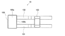
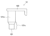
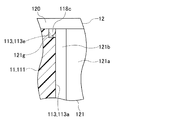
まず、図1〜図8を参照して車輪速度検出装置の構成について説明する。
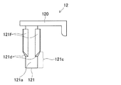
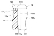
次に、第2実施形態の車輪速度検出装置について説明する。第2実施形態の車輪速度検出装置は、第1実施形態の車輪速度検出装置に対して、固定部材の軸部の形状を変更することで、軸部の押しつけ部側の外周面と孔部の押しつけ部側の内周面との間に全周に渡って隙間部が形成されるようにしたものである。
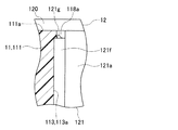
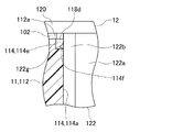
次に、第3実施形態の車輪速度検出装置について説明する。第3実施形態の車輪速度検出装置は、第1実施形態の車輪速度検出装置に対して、台座部材の孔部の形状を変更することで、軸部の押しつけ部側の外周面と孔部の押しつけ部側の内周面との間に全周に渡って隙間部が形成されるようにしたものである。
Claims (9)
- 本体部と、前記本体部から突出するリードとを備えた検出素子(10)と、
前記検出素子が固定される固定面を有する台座部材(11)と、
前記台座部材に固定され、前記本体部を前記台座部材に押しつけることなく前記リードを前記台座部材の前記固定面に押しつけ、前記検出素子を前記台座部材の前記固定面に固定する固定部材(12)と、
を有し、
前記台座部材は、前記固定部材が挿入される孔部(113、114)を有し、
前記固定部材は、
前記本体部を前記台座部材に押しつけることなく前記リードを前記台座部材に押しつける押しつけ部(120)と、
前記押しつけ部から突出し、前記孔部に挿入され、少なくとも一部が前記孔部と締まり嵌め状態になる軸部(121、122)と、
を有する検出装置。 - 本体部と、前記本体部から突出するリードとを備えた検出素子(10)と、
前記検出素子が固定される台座部材(11)と、
前記台座部材に固定され、前記本体部を覆うことなく前記リードの一部分を覆い、前記本体部を前記台座部材に押しつけることなく前記リードを前記台座部材に押しつけ、前記検出素子を前記台座部材に固定する固定部材(12)と、
を有し、
前記台座部材は、前記固定部材が挿入される孔部(113、114)を有し、
前記固定部材は、
前記本体部を前記台座部材に押しつけることなく前記リードを前記台座部材に押しつける押しつけ部(120)と、
前記押しつけ部から突出し、前記孔部に挿入され、少なくとも一部が前記孔部と締まり嵌め状態になる軸部(121、122)と、
を有する検出装置。 - 前記押しつけ部は、前記本体部近傍の前記リードの所定領域を前記台座部材に押しつける請求項1又は2に記載の検出装置。
- 前記軸部は、
前記押しつけ部から突出する柱部(121a、122a)と、
前記柱部の外周面から反軸心側に突出するとともに、前記柱部の軸方向に延在し、反軸心側に突出した先端部の軸方向の少なくとも一部が前記孔部と締まり嵌め状態になる複数のリブ(121b、122b)と、
を有する請求項1〜3のいずれか1項に記載の検出装置。 - 前記孔部は、
軸部挿入側に設けられ、前記軸部と締まり嵌め状態になる締まり嵌め部(113a、114a)と、
前記締まり嵌め部の反軸部挿入側に隣接して設けられ、前記軸部と隙間嵌め状態になる隙間嵌め部(113b、114b)と、
を有する請求項1〜4のいずれか1項に記載の検出装置。 - 前記軸部は、先端部に、先端に向かって細くなる先細り部(121c、122c)を有する請求項1〜5のいずれか1項に記載の検出装置。
- 前記軸部と前記孔部は、前記押しつけ部が前記台座部材の表面に接するまで前記軸部を前記孔部に挿入した場合に、前記軸部の押しつけ部側の端部の外周面と前記孔部の押しつけ部側の端部の内周面との間に全周に渡って隙間部が形成されるように構成されている請求項1〜6のいずれか1項に記載の検出装置。
- 前記軸部は、押しつけ部側の端部の外周面が前記孔部の押しつけ部側の端部の内周面より軸心側に離れて形成されている請求項7に記載の検出装置。
- 前記孔部は、押しつけ部側の端部の内周面が前記軸部の押しつけ部側の端部の外周面より反軸心側に離れて形成されている請求項7に記載の検出装置。
Priority Applications (3)
| Application Number | Priority Date | Filing Date | Title |
|---|---|---|---|
| US15/757,508 US10641784B2 (en) | 2015-09-07 | 2016-07-01 | Detection device |
| PCT/JP2016/069588 WO2017043160A1 (ja) | 2015-09-07 | 2016-07-01 | 検出装置 |
| CN201680032875.7A CN107615075B (zh) | 2015-09-07 | 2016-07-01 | 检测装置 |
Applications Claiming Priority (2)
| Application Number | Priority Date | Filing Date | Title |
|---|---|---|---|
| JP2015175738 | 2015-09-07 | ||
| JP2015175738 | 2015-09-07 |
Publications (3)
| Publication Number | Publication Date |
|---|---|
| JP2017053834A JP2017053834A (ja) | 2017-03-16 |
| JP2017053834A5 JP2017053834A5 (ja) | 2017-08-03 |
| JP6478117B2 true JP6478117B2 (ja) | 2019-03-06 |
Family
ID=58320699
Family Applications (1)
| Application Number | Title | Priority Date | Filing Date |
|---|---|---|---|
| JP2016026542A Active JP6478117B2 (ja) | 2015-09-07 | 2016-02-16 | 検出装置 |
Country Status (3)
| Country | Link |
|---|---|
| US (1) | US10641784B2 (ja) |
| JP (1) | JP6478117B2 (ja) |
| CN (1) | CN107615075B (ja) |
Families Citing this family (2)
| Publication number | Priority date | Publication date | Assignee | Title |
|---|---|---|---|---|
| CN113340740B (zh) * | 2021-06-02 | 2021-12-21 | 徐州海瑞电动车科技有限公司 | 电动车轮毂承压测试台 |
| CN114111916A (zh) * | 2021-12-24 | 2022-03-01 | 苏州国诚检测技术有限公司 | 一种环境检测仪 |
Family Cites Families (12)
| Publication number | Priority date | Publication date | Assignee | Title |
|---|---|---|---|---|
| JP2503659Y2 (ja) * | 1990-04-28 | 1996-07-03 | ソニー株式会社 | 素子取付け装置 |
| JP2003307523A (ja) * | 2002-04-16 | 2003-10-31 | Sumitomo Electric Ind Ltd | 回転検出センサ |
| US7305765B2 (en) * | 2002-10-18 | 2007-12-11 | Nsk Ltd. | Bearing unit for wheel and method of manufacturing the bearing unit |
| JP4179083B2 (ja) | 2003-07-08 | 2008-11-12 | 株式会社デンソー | 回転検出装置 |
| CN1853244B (zh) * | 2003-09-17 | 2010-06-16 | 日立粉末冶金株式会社 | 烧结可动铁心的制造方法 |
| JP2005227095A (ja) * | 2004-02-12 | 2005-08-25 | Sumiden Electronics Kk | 磁気変量センサ |
| JP4085079B2 (ja) | 2004-07-20 | 2008-04-30 | 住電エレクトロニクス株式会社 | 回転検出センサ |
| CN2901612Y (zh) * | 2006-02-10 | 2007-05-16 | 华为技术有限公司 | 一种用于与pcb板连接的连接器 |
| WO2009034979A1 (ja) * | 2007-09-12 | 2009-03-19 | Ntn Corporation | 車輪用軸受装置およびアクスルモジュール |
| DE102007060604A1 (de) * | 2007-12-13 | 2009-06-18 | Continental Teves Ag & Co. Ohg | Magnetfeld-Sensorelement |
| JP6017401B2 (ja) * | 2013-11-05 | 2016-11-02 | 愛三工業株式会社 | 回転角度検出センサ |
| CN104795674B (zh) * | 2015-04-22 | 2017-01-11 | 陕西华达科技股份有限公司 | 一种快速插拔连接器界面 |
-
2016
- 2016-02-16 JP JP2016026542A patent/JP6478117B2/ja active Active
- 2016-07-01 US US15/757,508 patent/US10641784B2/en active Active
- 2016-07-01 CN CN201680032875.7A patent/CN107615075B/zh active Active
Also Published As
| Publication number | Publication date |
|---|---|
| CN107615075A (zh) | 2018-01-19 |
| US20180245949A1 (en) | 2018-08-30 |
| US10641784B2 (en) | 2020-05-05 |
| CN107615075B (zh) | 2019-11-22 |
| JP2017053834A (ja) | 2017-03-16 |
Similar Documents
| Publication | Publication Date | Title |
|---|---|---|
| US8845193B2 (en) | Radial foil bearing | |
| EP2735751B1 (en) | Radial foil bearing | |
| JP4948040B2 (ja) | 回転子積層鉄心の樹脂封止方法 | |
| JP6478117B2 (ja) | 検出装置 | |
| JP5234522B2 (ja) | 回転検出装置およびその製造方法 | |
| US9206807B2 (en) | Preload disk spring, assembly structure thereof, and fan using same | |
| CN109562639A (zh) | 车轮轴承的密封装置及其制造方法 | |
| KR20120052174A (ko) | 모터 | |
| JP2013212009A (ja) | モータシャフト | |
| WO2017043160A1 (ja) | 検出装置 | |
| US20130249337A1 (en) | Hydrodynamic bearing module and spindle motor having the same | |
| JP2017053834A5 (ja) | ||
| JP6805892B2 (ja) | 検出装置 | |
| KR20150032800A (ko) | 수지 몰드 스테이터 및 그 제조 방법 | |
| JP2015216707A (ja) | モータおよびモータの製造方法 | |
| CN109586515B (zh) | 马达和传感器安装构造 | |
| JP5103000B2 (ja) | ロータコアのマグネットモールド方法およびその治具 | |
| US20110169359A1 (en) | Assembly structure of bearing and holder of brushless dc motor | |
| CN105003550A (zh) | 新型单轴连轴承装配装置及其装配方法 | |
| JP4859409B2 (ja) | 回転センサ付き軸受 | |
| KR102584905B1 (ko) | 모터 | |
| JP7243292B2 (ja) | モータ | |
| JP6231536B2 (ja) | スピンドルモータ | |
| JP2016220283A (ja) | アース用端子を備えたレゾルバステータ構造 | |
| CN118715419A (zh) | 旋转角度传感器单元、用于旋转角度传感器单元的壳体的盖和用于制造旋转角度传感器单元的方法 |
Legal Events
| Date | Code | Title | Description |
|---|---|---|---|
| A521 | Request for written amendment filed |
Free format text: JAPANESE INTERMEDIATE CODE: A523 Effective date: 20170626 |
|
| A621 | Written request for application examination |
Free format text: JAPANESE INTERMEDIATE CODE: A621 Effective date: 20170627 |
|
| A131 | Notification of reasons for refusal |
Free format text: JAPANESE INTERMEDIATE CODE: A131 Effective date: 20180628 |
|
| A521 | Request for written amendment filed |
Free format text: JAPANESE INTERMEDIATE CODE: A523 Effective date: 20180827 |
|
| TRDD | Decision of grant or rejection written | ||
| A01 | Written decision to grant a patent or to grant a registration (utility model) |
Free format text: JAPANESE INTERMEDIATE CODE: A01 Effective date: 20190110 |
|
| A61 | First payment of annual fees (during grant procedure) |
Free format text: JAPANESE INTERMEDIATE CODE: A61 Effective date: 20190123 |
|
| R151 | Written notification of patent or utility model registration |
Ref document number: 6478117 Country of ref document: JP Free format text: JAPANESE INTERMEDIATE CODE: R151 |
|
| R250 | Receipt of annual fees |
Free format text: JAPANESE INTERMEDIATE CODE: R250 |
|
| R250 | Receipt of annual fees |
Free format text: JAPANESE INTERMEDIATE CODE: R250 |
|
| R250 | Receipt of annual fees |
Free format text: JAPANESE INTERMEDIATE CODE: R250 |


