JP6445870B2 - Pneumatic tire - Google Patents
Pneumatic tire Download PDFInfo
- Publication number
- JP6445870B2 JP6445870B2 JP2015000469A JP2015000469A JP6445870B2 JP 6445870 B2 JP6445870 B2 JP 6445870B2 JP 2015000469 A JP2015000469 A JP 2015000469A JP 2015000469 A JP2015000469 A JP 2015000469A JP 6445870 B2 JP6445870 B2 JP 6445870B2
- Authority
- JP
- Japan
- Prior art keywords
- tread
- band
- tire
- main groove
- belt
- Prior art date
- Legal status (The legal status is an assumption and is not a legal conclusion. Google has not performed a legal analysis and makes no representation as to the accuracy of the status listed.)
- Expired - Fee Related
Links
Images


Landscapes
- Tires In General (AREA)
- Yarns And Mechanical Finishing Of Yarns Or Ropes (AREA)
Description
本発明は、車輌に装着される空気入りタイヤに関する。 The present invention relates to a pneumatic tire mounted on a vehicle.
特開2009−298236公報には、その軸方向両端部が折り返されたホールドベルトとインナーライナー内側に積層された補強シートを備えているタイヤが開示されている。このタイヤでは、ホールドベルトにより、トレッドの両端部の剛性が向上している。補強シートにより、トレッドの両端部間の領域の剛性が向上している。このタイヤは、高剛性に均一化されたトレッドを備えている。このタイヤは、高速走行に適している。 Japanese Patent Application Laid-Open No. 2009-298236 discloses a tire including a hold belt whose both axial ends are folded and a reinforcing sheet laminated on the inner liner inner side. In this tire, the rigidity of both end portions of the tread is improved by the hold belt. The reinforcing sheet improves the rigidity of the region between the two end portions of the tread. The tire includes a tread that is uniformed with high rigidity. This tire is suitable for high speed running.
特開2009−248573公報には、第一バンドと第二バンドとを備えるタイヤが開示されている。この第一バンドが軸方向一方から他方までの延在している。この第二バンドが第一バンドの軸方向端部に重ね合わされている。この第一バンドのコードと第二バンドのコードとが半径方向に重ね合わされてタイヤの半径方向外向きの成長を抑制している。このタイヤは、高速走行に適している。 Japanese Unexamined Patent Application Publication No. 2009-248573 discloses a tire including a first band and a second band. The first band extends from one axial direction to the other. This second band is superimposed on the axial end of the first band. The cord of the first band and the cord of the second band are overlapped in the radial direction to suppress the outward growth of the tire in the radial direction. This tire is suitable for high speed running.
車輌の高速走行性能の向上に伴い、装着されるタイヤには、更なる高速走行性能の向上が求められている。高速走行での発熱を抑制する観点から、トレッドの厚さを薄くすることが試みられている。しかしながら、トレッドの厚みを薄くすることは、タイヤの耐久性を損ない易い。 With the improvement of high-speed driving performance of vehicles, tires to be mounted are required to further improve high-speed driving performance. From the viewpoint of suppressing heat generation during high-speed running, attempts have been made to reduce the thickness of the tread. However, reducing the thickness of the tread tends to impair the durability of the tire.
本発明の目的は、高速走行での耐久性に優れた空気入りタイヤの提供にある。 An object of the present invention is to provide a pneumatic tire excellent in durability at high speed running.
本発明に係るタイヤは、路面に接地するトレッド面を備えるトレッドと、骨格を構成するカーカスと、カーカスを補強するベルト及びバンドとを備えている。上記カーカスは、半径方向外向きにトロイダル状に突出して延在している。上記ベルトは、上記カーカスの半径方向外側に積層されている。上記バンドは、第一バンドと第二バンドとを備えている。第一バンドは、上記ベルトの半径方向外側に積層されて上記ベルトを覆っている。第二バンドは、第一バンドの外側に積層されて上記ベルトを覆っている。上記トレッドは、上記バンドの半径方向外側に積層されている。上記第一バンド及び第二バンドのそれぞれは、周方向に延びるバンドコードとバンドコードを覆おうトッピングゴムとを備えている。上記トレッドには、軸方向内側で周方向に延びる一対の第一主溝と、この第一主溝の軸方向外側で周方向に延びる第二主溝とが刻まれている。上記トレッドは、一対の第一主溝の間のセンターブロックと、第一主溝と第二主溝との間の一対のミドルブロックと、第二主溝の軸方向外側の一対のショルダーブロックとに分割されている。上記一対のミドルブロックのそれぞれのトレッド面の面積Smは、上記センターブロックのトレッド面の面積Scより大きくされている。この面積Scは、上記一対のショルダーブロックのそれぞれの第二主溝からトレッド端までのトレッド面の面積Ssより大きくされている。
一方のトレッド端から他方のトレッド端までのトレッド幅を幅Wtとし、赤道面における接地長をLcとし、赤道面からトレッド端に向かって0.4Wtの位置における接地長をLsとしたときに、この接地長Lsに対する接地長Lcの比(Lc/Ls)は、1.05以上1.35以下にされている。赤道面における上記トレッドの厚さTcと赤道面からトレッド端に向かって0.4Wtの位置における上記トレッドの厚さTsとの差(Tc−Ts)は、0以上1.0mm以下にされている。
The tire according to the present invention includes a tread having a tread surface that comes in contact with the road surface, a carcass constituting a skeleton, and a belt and a band for reinforcing the carcass. The carcass extends in a toroidal shape outward in the radial direction. The belt is laminated on the outside of the carcass in the radial direction. The band includes a first band and a second band. The first band is laminated on the outer side in the radial direction of the belt and covers the belt. The second band is laminated outside the first band and covers the belt. The tread is stacked on the radially outer side of the band. Each of the first band and the second band includes a band cord extending in the circumferential direction and a topping rubber that covers the band cord. The tread has a pair of first main grooves extending in the circumferential direction on the inner side in the axial direction, and a second main groove extending in the circumferential direction on the outer side in the axial direction of the first main groove. The tread includes a center block between a pair of first main grooves, a pair of middle blocks between the first main grooves and the second main grooves, and a pair of shoulder blocks on the outer side in the axial direction of the second main grooves. It is divided into The area Sm of each tread surface of the pair of middle blocks is larger than the area Sc of the tread surface of the center block. The area Sc is larger than the area Ss of the tread surface from the second main groove to the tread end of each of the pair of shoulder blocks.
When the tread width from one tread end to the other tread end is the width Wt, the contact length at the equator plane is Lc, and the contact length at the position 0.4 Wt from the equator plane toward the tread end is Ls, The ratio (Lc / Ls) of the contact length Lc to the contact length Ls is set to 1.05 or more and 1.35 or less. The difference (Tc−Ts) between the thickness Tc of the tread on the equator plane and the thickness Ts of the tread at a position of 0.4 Wt from the equator plane toward the tread end is set to 0 to 1.0 mm. .
好ましくは、上記第一バンド及び第二バンドのそれぞれのバンドコードは、アラミド繊維からなる第一ストランドと、熱収縮性の有機繊維からなる第二ストランドとを撚り合わせた複合コードからなっている。 Preferably, each band cord of the first band and the second band is composed of a composite cord in which a first strand made of an aramid fiber and a second strand made of a heat-shrinkable organic fiber are twisted together.
好ましくは、上記第一主溝及び第二主溝の溝底のトレッドの厚さは、1.6mm以上にされている。 Preferably, the thickness of the tread at the bottom of the first main groove and the second main groove is 1.6 mm or more.
好ましくは、上記トレッドの厚さTcは、9.6mm以下にされている。 Preferably, the thickness Tc of the tread is 9.6 mm or less.
本発明に係る空気入りタイヤは、上記ベルト及びバンドとにより高い剛性を発揮する。このタイヤでは、上記ベルト及びバンドと上記トレッドとの組み合わせにより、路面と接地形状、接地圧が適正化されている。このタイヤは、トレッドの厚さを薄くしても、十分な耐久性を発揮しうる。このタイヤでは、トレッドの厚さを薄くして高速走行での発熱を抑制しうる。このタイヤは、高速走行での耐久性に優れている。 The pneumatic tire according to the present invention exhibits high rigidity due to the belt and the band. In this tire, the road surface, the contact shape, and the contact pressure are optimized by the combination of the belt and band and the tread. This tire can exhibit sufficient durability even when the thickness of the tread is reduced. In this tire, the thickness of the tread can be reduced to suppress heat generation at high speeds. This tire is excellent in durability at high speeds.
以下、適宜図面が参照されつつ、好ましい実施形態に基づいて本発明が詳細に説明される。 Hereinafter, the present invention will be described in detail based on preferred embodiments with appropriate reference to the drawings.
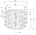
図1には、空気入りタイヤ2が示されている。図1において、上下方向がタイヤ2の半径方向であり、左右方向がタイヤ2の軸方向であり、紙面との垂直方向がタイヤ2の周方向である。図1において、一点鎖線CLはタイヤ2の赤道面を表わす。このタイヤ2の形状は、トレッドパターンを除いて、赤道面に対して対称である。
FIG. 1 shows a
このタイヤ2は、トレッド4、一対のサイドウォール6、一対のクリンチ8、一対のビード10、カーカス12、ベルト14、バンド16、インナーライナー18、一対のチェーファー20を備えている。このタイヤ2は、チューブレスタイプである。このタイヤ2は、四輪車輌に装着される。
The
トレッド4は、半径方向外向きに凸な形状を呈している。トレッド4は、路面と接地するトレッド面22を形成する。このトレッド4には、溝24が刻まれている。この溝24により、トレッドパターンが形成される。トレッド4は、ベース層26とキャップ層28とを有している。キャップ層28は、ベース層26の半径方向外側に位置している。キャップ層28は、ベース層26に積層されている。ベース層26は、接着性に優れた架橋ゴムからなる。ベース層26の典型的な基材ゴムは、天然ゴムである。キャップ層28は、耐摩耗性、耐熱性及びグリップ性に優れた架橋ゴムからなる。
The tread 4 has a shape protruding outward in the radial direction. The tread 4 forms a
それぞれのサイドウォール6は、トレッド4の端から半径方向略内向きに延びている。このサイドウォール6の半径方向外側端は、トレッド4と接合されている。このサイドウォール6の半径方向内側端は、クリンチ8と接合されている。このサイドウォール6は、耐カット性及び耐候性に優れた架橋ゴムからなる。このサイドウォール6は、カーカス12の損傷を防止する。
Each
それぞれのクリンチ8は、サイドウォール6の半径方向略内側に位置している。クリンチ8は、軸方向において、ビード10及びカーカス12よりも外側に位置している。クリンチ8は、耐摩耗性に優れた架橋ゴムからなる。クリンチ8は、リムのフランジと当接する。サイドウォール6とクリンチ8とに跨がって、リブ30が形成されている。リブ30は、軸方向外側に向かって突出している。このタイヤ2が装着されるリムのフランジの損傷を、リブ30は防止する。このリブ30は、サイドウォール6に形成されてもよい。また、このリブ30は、クリンチ8に形成されてもよい。
Each
それぞれのビード10は、クリンチ8の軸方向内側に位置している。ビード10は、コア32と、このコア32から半径方向外向きに延びるエイペックス34とを備えている。コア32はリング状であり、巻回された非伸縮性ワイヤーを含む。ワイヤーの典型的な材質は、スチールである。エイペックス34は、半径方向外向きに先細りである。エイペックス34は、高硬度な架橋ゴムからなる。
Each
カーカス12は、第一プライ36及び第二プライ38からなる。第一プライ36及び第二プライ38は、両側のビード10の間に架け渡されており、半径方向外向きにトロイダル上に突出して延在している。このカーカス12は、タイヤ2の骨格を構成している。第一プライ36及び第二プライ38は、トレッド4及びサイドウォール6に沿っている。第一プライ36は、コア32の周りにて、軸方向内側から外側に向かって折り返されている。この折り返しにより、第一プライ36には、主部36aと折り返し部36bとが形成されている。第二プライ38は、コア32の周りにて、軸方向内側から外側に向かって折り返されている。この折り返しにより、第二プライ38には、主部38aと折り返し部38bとが形成されている。第一プライ36の折り返し部36bの端は、半径方向において、第二プライ38の折り返し部38bの端よりも外側に位置している。
The
第一プライ36及び第二プライ38のそれぞれは、並列された多数のコードとトッピングゴムとからなる。それぞれのコードが赤道面に対してなす角度の絶対値は、75°から90°である。それぞれのコードが赤道面に対してなす角度の絶対値は、75°から90°である。換言すれば、このカーカス12はラジアル構造を有する。これらのコードは、有機繊維からなる。好ましい有機繊維として、ポリエステル繊維、ナイロン繊維、レーヨン繊維、ポリエチレンナフタレート繊維及びアラミド繊維が例示される。カーカス12が、1枚のプライから形成されてもよい。
Each of the
ベルト14は、トレッド4の半径方向内側に位置している。ベルト14は、カーカス12と積層されている。ベルト14は、カーカス12を補強する。ベルト14は、内側層40及び外側層42からなる。図1から明らかなように、軸方向において、内側層40の幅は外側層42の幅よりも若干大きい。
The
この内側層40は、図示されないが、並列された多数のベルトコードとトッピングゴムとからなる。外側層42は、並列された多数のベルトコードとトッピングゴムとからなる。内側層40及び外側層42のそれぞれのベルトコードは、赤道面に対して傾斜している。傾斜角度の一般的な絶対値は、10°以上35°以下である。内側層40のベルトコードの赤道面に対する傾斜方向は、外側層42のベルトコードの赤道面に対する傾斜方向とは逆である。これらのベルトコードの好ましい材質は、スチールである。これらのベルトコードに、有機繊維が用いられてもよい。ベルト14が、3以上の層を備えてもよい。
Although not shown in the drawing, the
バンド16は、ベルト14の半径方向外側に位置している。バンド16は、ベルト14の外側層42の外側面に積層されている。軸方向において、バンド16の幅はベルト14の幅よりも大きい。バンド16は、ベルト14を覆っている。バンド16は、第一バンド44及び第二バンド46とからなる。第一バンド44及び第二バンド46のそれぞれがベルト14を覆っている。この第一バンド44及び第二バンド46のそれぞれは、軸方向一方端から他方端まで延在してベルト14を覆っている。この第一バンド44及び第二バンド46は、所謂フルバンドである。
The
この第一バンド44は、図示されないが、バンドコードとトッピングゴムとからなる。バンドコードは、タイヤ2の周方向に螺旋状に巻かれている。この第一バンド44は、いわゆるジョイントレス構造を有する。第二バンド46は、第一バンド44と同様に、バンドコードとトッピングゴムとからなる。バンドコードは、周方向に螺旋状に巻かれている。この第二バンド46は、いわゆるジョイントレス構造を有する。第一バンド44及び第二バンド46のそれぞれのバンドコードは、実質的に周方向に延びている。周方向に対するバンドコードの角度は、5°以下、さらには2°以下である。第一バンド44及び第二バンド46はベルト14を拘束する。第一バンド44及び第二バンド46は、ベルト14のリフティングを抑制する。
Although not shown, the
第一バンド44及び第二バンド46のそれぞれのバンドコードは、アラミド繊維からなる第一ストランドと熱収縮性の有機繊維から第二ストランドとが撚り合わされた複合材料からなっている。この熱収縮性の有機繊維として、ナイロン、ポリエチレンテレフタレート繊維、ポリエチレンナフタレート繊維等が例示される。ここでは、ストランドは、繊維からなる糸が撚り合わされた束を意味する。この熱収縮性の有機繊維として、熱収縮率が3.0%以上のものが好適である。この熱収縮率は、JIS−L1017の8.10(b)項の「加熱後乾熱収縮率(B法)」に準じ、コードを無荷重の状態にて温度180゜Cで30分間加熱した後の加熱後乾熱収縮率を意味する。この第一バンド44及び第二バンド46のそれぞれのバンドコードは、複合材料に代えて有機繊維からなってもよい。この好ましい有機繊維として、ナイロン繊維、レーヨン繊維、ポリエチレンテレフタレート繊維、ポリエチレンナフタレート繊維及びアラミド繊維が例示される。
Each band cord of the
インナーライナー18は、カーカス12の内側に位置している。インナーライナー18は、カーカス12の内面に接合されている。インナーライナー18とカーカス12とがインスレーションゴムを介して接合されてもよい。インナーライナー18は、空気遮蔽性に優れた架橋ゴムからなる。インナーライナー18の典型的な基材ゴムは、ブチルゴム又はハロゲン化ブチルゴムである。インナーライナー18は、タイヤ2の内腔面48を形成している。インナーライナー18は、タイヤ2の内圧を保持する。
The
それぞれのチェーファー20は、ビード10の近傍に位置している。タイヤ2がリムに組み込まれると、このチェーファー20がリムと当接する。この当接により、ビード10の近傍が保護される。この実施形態では、チェーファー20が、布とこの布に含浸したゴムとからなっている。チェーファー20は、クリンチ8と一体であってもよい。チェーファー20の材質はクリンチ8の材質と同じであってもよい。
Each
図1の点Ptは、トレッド端を表している。トレッド端Ptは、トレッド面22の軸方向外端であって、外観上明瞭なエッジによって識別しうるときには当該エッジとする。外観上識別が困難な場合には、正規内圧のタイヤ2に正規荷重を負荷してキャンバー角0゜でトレッド4を平面に接地させたときの最も軸方向外側で平面に接地する接地端が、トレッド端Ptとされる。
A point Pt in FIG. 1 represents the tread edge. The tread end Pt is the outer end in the axial direction of the
両矢印Wtは、トレッド幅を表している。このトレッド幅Wtは、軸方向一方のトレッド端Ptから他方のトレッド端Ptまでの距離として測定される。両矢印Wsは、トレッド幅Wtの0.8倍の幅を表している。このトレッド幅Wt及び幅Wsは、トレッド面22に沿って測定される。点Psは、この幅Wsのトレッド面22上の点を表している。この点Psは、赤道面からトレッド端Ptに向かってトレッド幅Wtの0.4倍の位置を表している。
The double arrow Wt represents the tread width. The tread width Wt is measured as a distance from one tread end Pt in the axial direction to the other tread end Pt. A double arrow Ws represents a width that is 0.8 times the tread width Wt. The tread width Wt and the width Ws are measured along the
両矢印Tcは、赤道面におけるトレッド4の厚さを表している。両矢印Tsは、点Pssにおけるトレッド4の厚さを表している。両矢印Tgは、主溝24の底面におけるトレッド4の厚さを表している。この厚さTc、Ts及びTgは、ベース層26とキャップ層28とを合わせた厚さである。厚さTgは、主溝24の底面において、最も厚さの薄くなる位置で測定される。このタイヤ2では、第一主溝24aと第二主溝24bとで底面におけるトレッド4の厚さは同じにされている。この第一主溝24aと第二主溝24bとで底面におけるトレッド4の厚さが異なる場合には、厚さの薄い方が厚さTgとされる。
A double-headed arrow Tc represents the thickness of the tread 4 on the equator plane. A double-headed arrow Ts represents the thickness of the tread 4 at the point Pss. A double-headed arrow Tg represents the thickness of the tread 4 on the bottom surface of the
図2に示される様に、トレッド4には、一対の第一主溝24aと、一対の第二主溝24bと、複数の第一横溝24cと、複数の第二横溝24dが刻まれている。一対の第一主溝24aは、周方向の延在している。第一主溝24aは、周方向にトレッド面22を一周している。一対の第一主溝24aは、赤道面に対して対称に形成されている。一対の第二主溝24bは、周方向の延在している。一対の第二主溝24bは、周方向にトレッド面22を一周している。一対の第二主溝24bは、赤道面に対して対称に形成されている。第一主溝24aは第二主溝24bより軸方向内側に位置している。
As shown in FIG. 2, the tread 4 has a pair of first
このトレッド4は、一対の第一主溝24aの間のセンターブロック50と、第一主溝24aと第二主溝24bとの間のミドルブロック52と、第二主溝24bの軸方向外側のショルダーブロック54とに区画されている。
The tread 4 includes a
第一横溝24cは、センターブロック50、一方のミドルブロック52及び一方のショルダーブロック54に跨がって刻まれている。この第一横溝24cは、センターブロック50の赤道面の近傍から赤道面と交差して一方のショルダーブロック54までの延びている。この第一横溝24cは、第一主溝24a及び第二主溝24bと交差して延びている。第二横溝24dは、一方のミドルブロック52及び一方のショルダーブロック54に跨がって刻まれている。第二横溝24dは、第二主溝24bと交差して延びている。
The first
軸方向一方の第一横溝24cと他方の第一横溝24cとは、赤道面上の点に対して点対称に形成されている。軸方向一方の第二横溝24dと他方の第二横溝24dとは、赤道面上の点に対して点対称に形成されている。第一横溝24c及び第二横溝24dは、周方向に交互に形成されている。複数の第一横溝24c及び複数の第二横溝24dは、周方向に並べて形成されている。
The first
図2の両矢印Cは、センターブロック50の領域を表している。この領域Cは、一方の第一主溝24aと他方の第一主溝24aとで区画されるトレッド面22の領域を表している。両矢印Mは、一対のミドルブロック52のそれぞれの領域を表している。この領域Mは、第一主溝24aと第二主溝24bとで区画されるトレッド面22の領域を表している。両矢印Sは、一対のショルダーブロック54のそれぞれの領域を表している。この領域Sは、第二主溝24bとトレッド端Ptとで区画されるトレッド面22の領域を表している。
A double arrow C in FIG. 2 represents the area of the
このセンターブロック50の領域Cの面積は、面積Scで表される。ミドルブロック52のそれぞれの領域Mの面積は、面積Smで表される。ショルダーブロック54のそれぞれの領域Sの面積は、面積Ssで表される。このタイヤ2では、面積Smは面積Scより大きくされている。この面積Scは、面積Ssより大きくされている。この面積Sm、Sc及びSsのそれぞれは、タイヤ2のトレッド面22の全周に亘って求められる。従って、この面積Scの面積と、面積Smの2倍の面積と、面積Ssの2倍の面積との合計は、タイヤ2のトレッド面の面積に等しい。
The area of the region C of the
図3には、タイヤ2のトレッド面22の接地面が示されている。この接地面は、タイヤ2に正規内圧の空気が充填されて、正規荷重を負荷して、キャンバー角を0゜として、トレッド4を平面の路面に接地させて得られている。両矢印Lcは、赤道面でのトレッド面22の接地長を表している。両矢印Lsは、赤道面からトレッド端Ptに向かってトレッド幅Wtの0.4倍の位置Psでの、トレッド面22の接地長を表している。点Pαは、周方向を区切る接地境界を示す輪郭上の点を表している。二点鎖線L1は、軸方向の延びる直線を表している。二点鎖線L2は、点Pαを通る輪郭の接線を表している。両矢印αは、直線L1と接線L2とのなす角度である。この角度αは、点Pαにおける輪郭の傾き角を表している。
FIG. 3 shows a ground contact surface of the
この接地面では、周方向の接地境界の輪郭は、軸方向内側から外側に向かって、周方向外側から内側に向かって傾斜して延びる曲線になっている。周方向の接地長において、接地長Lcが最も長くなっている。トレッド端Ptにおける接地長が最も短くなっている。赤道面からトレッド端に向かって、徐々に、接地長が短くなっている。このタイヤ2では、赤道面からトレッド端に向かって、輪郭の傾き角αが徐々に大きくなっている。
In this ground contact surface, the contour of the ground contact boundary in the circumferential direction is a curved line extending incline from the inner side in the axial direction toward the outer side and from the outer side in the circumferential direction toward the inner side. The contact length Lc is the longest in the contact length in the circumferential direction. The contact length at the tread end Pt is the shortest. The ground contact length gradually decreases from the equator to the tread edge. In the
このタイヤ2が路面に接地すると、センターブロック50の接地圧が高くなり易い。高速走行では、センターブロック50で発熱し易く蓄熱され易い。このタイヤ2では、面積Smが面積Scより大きくされているので、センターブロック50の発熱が抑制されている。一方で、面積Scは面積Ssより大きいので、センターブロック50の偏摩耗が抑制されている。
When the
このタイヤ2では、面積Scが面積Ssより大きくされると共に、ショルダー領域Sの接地長Lsに対して、センター領域Cの接地長Lcの比(Lc/Ls)が、1.05以上にされることで、センターブロック50の偏摩耗が効果的に抑制されている。この観点から、この比(Lc/Ls)は、好ましくは1.10以上であり、更に好ましくは1.15以上である。一方で、この比(Lc/Ls)が1.35以下にされることで、ショルダーブロック54の偏摩耗、所謂肩落ち摩耗が抑制されている。この観点から、この比(Lc/Ls)は、好ましくは1.30以下であり、更に好ましくは1.25以下である。
In the
更に、このタイヤ2では、赤道面でのトレッド4の厚さTcと点Psにおけるトレッド4の厚さTsとの差(Tc−Ts)は、0以上にされている。これにより、前述の比(Lc/Ls)が容易に1.05以上にされうる。一方で、この厚さTcが厚くなり過ぎると、センターブロック50の発熱量が大きくなり易い。この観点から、この厚さTcは薄い方が好ましく、この厚さTcは9.6mm以下が好ましい。また、この厚さTcが薄くされることに伴い厚さTsが薄くされる。この厚さTsが薄くなりすぎると、第二主溝24bの溝底の厚さTgを十分な厚さにすることが困難になる。これらの観点から、この差(Tc−Ts)は、1.0mm以下にされている。好ましくは、この差(Tc−Ts)は、0.5mm以下である。
Further, in the
第一主溝及び第二主溝の溝底のトレッド4の厚さTgが薄くなると、ベルト14とバンド16との保護効果が得られ難い。厚さTgが薄くなると、溝底が繰り返し歪みにより疲労し、クラックが生じることがある。このクラックの発生は、TGCと称される。このTGCの発生を抑制する観点から、この厚さTgは、好ましくは1.6mm以上である。
When the thickness Tg of the tread 4 at the bottom of the first main groove and the second main groove is reduced, it is difficult to obtain the protection effect between the
このタイヤ2では、第一バンド14と第二バンド16とがベルト14を拘束する。この第一バンド14と第二バンド16は、剛性の向上に寄与する。これにより、高速走行でのトレッド4のリフティングが抑制される。好ましくは、この第一バンド14及び第二バンド16のそれぞれのバンドコードは、アラミド繊維からなる第一ストランドと、熱収縮性の有機繊維からなる第二ストランドとを撚り合わせた複合コードからなる。この複合コードからなるバンドコードにより、高い拘束力が発揮されうる。
In the
本発明では、タイヤ2の各部材の寸法及び角度は、タイヤ2が正規リムに組み込まれ、正規内圧となるようにタイヤ2に空気が充填された状態で測定される。特に言及されない限り、測定時には、タイヤ2には荷重がかけられない。本明細書において正規リムとは、タイヤ2が依拠する規格において定められたリムを意味する。JATMA規格における「標準リム」、TRA規格における「Design Rim」、及びETRTO規格における「Measuring Rim」は、正規リムである。本明細書において正規内圧とは、タイヤ2が依拠する規格において定められた内圧を意味する。JATMA規格における「最高空気圧」、TRA規格における「TIRE LOAD LIMITS AT VARIOUS COLD INFLATION PRESSURES」に掲載された「最大値」、及びETRTO規格における「INFLATION PRESSURE」は、正規内圧である。本明細書において正規荷重とは、タイヤ2が依拠する規格において定められた荷重を意味する。JATMA規格における「最高負荷能力」、TRA規格における「TIRE LOAD LIMITS AT VARIOUS COLD INFLATION PRESSURES」に掲載された「最大値」、及びETRTO規格における「LOAD CAPACITY」は、正規荷重である。
In the present invention, the size and angle of each member of the
以下、実施例によって本発明の効果が明らかにされるが、この実施例の記載に基づいて本発明が限定的に解釈されるべきではない。 Hereinafter, the effects of the present invention will be clarified by examples. However, the present invention should not be construed in a limited manner based on the description of the examples.
[実施例1]
図1の構造を備えたタイヤが準備された。このタイヤのサイズは、235/45ZR17であった。このタイヤの仕様は、表1に示されている。バンドの構造の2Fは、バンドが2枚のフルバンドからなること意味する。このバンドのコード材質のHBは、複合コードを意味する。このバンドコードは、アラミド繊維からなる第一ストランドとナイロン繊維からなる第二ストランドとが撚り合わされた複合材料からなっていた。トレッドの主溝の溝底の厚さTgと、トレッドの厚さTcと厚さTsとの差(Tc−Ts)と、接地長Lsに対する接地長Lcの比(Lc/Ls)とは、それぞれ表1に示される通りであった。表1のトレッド面積は、一対のミドルブロックのそれぞれの面積Smが、センターブロックの面積Scより大きくされており、この面積Scが、一対のショルダーブロックのそれぞれの面積Ssより大きくされていることを示している。
[Example 1]
A tire having the structure of FIG. 1 was prepared. The tire size was 235 / 45ZR17. The specification of this tire is shown in Table 1. The band structure 2F means that the band is composed of two full bands. The band cord material HB means a composite cord. This band cord was made of a composite material in which a first strand made of aramid fibers and a second strand made of nylon fibers were twisted together. The groove bottom thickness Tg of the tread main groove, the difference between the tread thickness Tc and the thickness Ts (Tc−Ts), and the ratio of the contact length Lc to the contact length Ls (Lc / Ls) are respectively It was as shown in Table 1. The tread area in Table 1 is that each area Sm of the pair of middle blocks is larger than the area Sc of the center block, and this area Sc is larger than each area Ss of the pair of shoulder blocks. Show.
[実施例2]
バンドコードがナイロン繊維からなる他は実施例1と同様にしてタイヤが得られた。表1のバンドのコード材質のNBは、ナイロン繊維からなるバンドコードを表している。
[Example 2]
A tire was obtained in the same manner as in Example 1 except that the band cord was made of nylon fiber. The band cord material NB in Table 1 represents a band cord made of nylon fiber.
[比較例1]
バンドの構造が1枚のフルバンドとフルバンドの軸方向端部を覆う一対のエッジバンドとからなる他は、実施例1と同様にして、タイヤを得た。表2の構造のE+Fは、一対のエッジバンドとフルバンドとからなることを示している。
[Comparative Example 1]
A tire was obtained in the same manner as in Example 1 except that the band structure consisted of one full band and a pair of edge bands covering the axial end of the full band. E + F in the structure of Table 2 indicates that it consists of a pair of edge bands and full bands.
[実施例3−4及び比較例2]
トレッドの厚さTcと厚さTsとの差(Tc−Ts)が表1に示される様にされた他は実施例1と同様にして、タイヤを得た。
[Example 3-4 and Comparative Example 2]
A tire was obtained in the same manner as in Example 1 except that the difference (Tc−Ts) between the thickness Tc and the thickness Ts of the tread was as shown in Table 1.
[実施例5−6及び比較例3]
トレッドの主溝の溝底の厚さTgが表2に示される様にされた他は実施例1と同様にして、タイヤを得た。
[Examples 5-6 and Comparative Example 3]
A tire was obtained in the same manner as in Example 1 except that the thickness Tg of the groove bottom of the main groove of the tread was set as shown in Table 2.
[実施例7−8及び比較例4−5]
接地長Lsに対する接地長Lcの比(Lc/Ls)が表3に示される様にされた他は実施例1と同様にして、タイヤを得た。
[Examples 7-8 and Comparative Example 4-5]
Tires were obtained in the same manner as in Example 1 except that the ratio of the contact length Lc to the contact length Ls (Lc / Ls) was as shown in Table 3.
[比較例6]
面積Smが面積Scより小さくされて、この面積Smが面積Ssより大きくされた他は、実施例1と同様にしてタイヤを得た。
[Comparative Example 6]
A tire was obtained in the same manner as in Example 1 except that the area Sm was made smaller than the area Sc and the area Sm was made larger than the area Ss.
[偏摩耗及びTGC]
タイヤを正規リムに組み込み、このタイヤに正規内圧で空気を充填した。このタイヤを、四輪車輌に装着した。レーシングサーキットを平均時速150km/hで高速走行させた。走行後のタイヤの外観が検査された。トレッドのセンター摩耗、ショルダー肩落ち摩耗等の偏摩耗の有無が検査された。併せて、トレッドの主溝底面のひび割れの有無が検査された。その結果が、下記の表1から表3に示されている。表1から3の偏摩耗の欄において、偏摩耗が確認されなかったものは良とされ、偏摩耗が確認されたものは、不可とされている。また、TGCの欄において、主溝の底面にクラックが確認されなかったものは良とされ、クラックが確認されたものは不可とされている。
[Uneven wear and TGC]
A tire was incorporated into a regular rim, and the tire was filled with air at a regular internal pressure. This tire was mounted on a four-wheel vehicle. The racing circuit was driven at a high speed at an average speed of 150 km / h. The appearance of the tire after running was inspected. Existence of uneven wear such as tread center wear and shoulder shoulder wear was examined. In addition, the bottom surface of the main groove of the tread was inspected for cracks. The results are shown in Tables 1 to 3 below. In the column of uneven wear in Tables 1 to 3, the case where uneven wear was not confirmed is considered good, and the case where uneven wear was confirmed is not acceptable. Further, in the TGC column, the case where no crack is confirmed on the bottom surface of the main groove is regarded as good, and the case where the crack is confirmed is regarded as impossible.
[H/S性能]
タイヤのハイスピード性能は、中国規格GB/T4502−2009に準拠して評価された。タイヤを正規リムに組み込み、このタイヤに空気を充填して内圧を320kPaとした。このタイヤをドラム式走行試験機に装着し、GB/T4502−2009により規定された荷重/速度性能テストに準拠して、ステップスピード方式により、ハイスピード性能の評価がされた。このテストでは、段階的に10km/hずつ走行速度を上昇させた。それぞれの走行速度で所定時間、タイヤを走行させた。タイヤが破壊するまで速度を段階的に上昇させていき、破壊したときの速度と走行時間が測定された。この結果は、表1から3のH/S性能の欄に示されている。この結果は、破壊に至った速度と、破壊に至ったその速度での走行時間とで示されている。例えば、実施例1の「350−8」は、350km/hで8分走行後に破壊したことを表している。破壊に至った速度が大きい結果ほど、高速走行に優れている。同じ速度では破壊に至った時間が長い結果ほど、高速走行に優れている。
[H / S performance]
The high speed performance of the tire was evaluated according to the Chinese standard GB / T4502-2009. A tire was incorporated into a regular rim, and the tire was filled with air to adjust the internal pressure to 320 kPa. This tire was mounted on a drum type driving test machine, and high speed performance was evaluated by a step speed method in accordance with a load / speed performance test defined by GB / T4502-2009. In this test, the traveling speed was increased stepwise by 10 km / h. The tires were run for a predetermined time at each running speed. The speed was gradually increased until the tire broke, and the speed and running time when the tire broke were measured. The results are shown in the H / S performance column of Tables 1 to 3. This result is shown by the speed that led to the destruction and the travel time at that speed that led to the destruction. For example, “350-8” in Example 1 indicates that the vehicle broke down after traveling for 8 minutes at 350 km / h. The higher the speed at which destruction occurred, the better the high speed driving. The longer the time taken to break at the same speed, the better the driving speed is.

表1から3に示されるように、実施例のタイヤは、比較例のタイヤに比べて、高速走行での耐久性に優れている。この評価結果から、本発明の優位性は明らかである。 As shown in Tables 1 to 3, the tires of the examples are superior in durability at high speeds compared to the tires of the comparative examples. From this evaluation result, the superiority of the present invention is clear.
以上説明されたタイヤは、車輌に装着されるタイヤに広く適用されうる。このタイヤは、高速走行する車輌のタイヤに特に適している。 The tire described above can be widely applied to tires mounted on vehicles. This tire is particularly suitable as a tire for a vehicle that travels at a high speed.
2・・・タイヤ
4・・・トレッド
6・・・サイドウォール
8・・・クリンチ
10・・・ビード
12・・・カーカス
14・・・ベルト
16・・・バンド
18・・・インナーライナー
20・・・チェーファー
22・・・トレッド面
24・・・溝
36・・・第一プライ
38・・・第二プライ
40・・・内側層
42・・・外側層
44・・・第一バンド
46・・・第二バンド
50・・・センターブロック
52・・・ミドルブロック
54・・・ショルダーブロック
2 ... tyre 4 ... tread 6 ...
Claims (3)
上記カーカスが半径方向外向きにトロイダル状に突出して延在しており、
上記ベルトが上記カーカスの半径方向外側に積層されており、
上記バンドが第一バンドと第二バンドとを備えており、第一バンドが上記ベルトの半径方向外側に積層されて上記ベルトを覆っており、第二バンドが第一バンドの外側に積層されて上記ベルトを覆っており、
上記トレッドが上記バンドの半径方向外側に積層されており、
上記第一バンド及び第二バンドのそれぞれが周方向に延びるバンドコードとバンドコードを覆おうトッピングゴムとを備えており、
上記トレッドには、軸方向内側で周方向に延びる一対の第一主溝と、この第一主溝の軸方向外側で周方向に延びる第二主溝とが刻まれており、
上記トレッドが一対の第一主溝の間のセンターブロックと、第一主溝と第二主溝との間の一対のミドルブロックと、第二主溝の軸方向外側の一対のショルダーブロックとに分割されており、
上記一対のミドルブロックのそれぞれのトレッド面の面積Smが上記センターブロックのトレッド面の面積Scより大きくされており、この面積Scが上記一対のショルダーブロックのそれぞれの第二主溝からトレッド端までのトレッド面の面積Ssより大きくされており、
一方のトレッド端から他方のトレッド端までのトレッド幅を幅Wtとし、赤道面における接地長をLcとし、赤道面からトレッド端に向かって0.4Wtの位置における接地長をLsとしたときに、この接地長Lsに対する接地長Lcの比(Lc/Ls)が1.05以上1.35以下にされており、
赤道面における上記トレッドの厚さTcと赤道面からトレッド端に向かって0.4Wtの位置における上記トレッドの厚さTsとの差(Tc−Ts)が0以上1.0mm以下にされており、
上記第一主溝及び第二主溝の溝底のトレッドの厚さが1.6mm以上にされており、
正規内圧の空気が充填されて正規荷重が負荷されたときの接地面の輪郭が、軸方向内側から外側に向かって周方向外側から内側に向かって傾斜して延びており、周方向の接地長が、接地長Lcで最も長く、トレッド端での接地長で最も短くなっている空気入りタイヤ。 A tread having a tread surface that contacts the road surface, a carcass constituting a skeleton, a belt and a band for reinforcing the carcass,
The carcass extends to protrude in a toroidal shape outward in the radial direction,
The belt is laminated radially outward of the carcass;
The band includes a first band and a second band, the first band is laminated on the outer side in the radial direction of the belt and covers the belt, and the second band is laminated on the outer side of the first band. Covering the belt,
The tread is laminated radially outward of the band;
Each of the first band and the second band includes a band cord extending in the circumferential direction and a topping rubber covering the band cord,
The tread is engraved with a pair of first main grooves extending in the circumferential direction on the inner side in the axial direction and a second main groove extending in the circumferential direction on the outer side in the axial direction of the first main groove,
The tread includes a center block between the pair of first main grooves, a pair of middle blocks between the first main groove and the second main groove, and a pair of shoulder blocks outside the second main groove in the axial direction. Divided,
The area Sm of each tread surface of the pair of middle blocks is larger than the area Sc of the tread surface of the center block, and this area Sc extends from the second main groove to the tread edge of each of the pair of shoulder blocks. It is made larger than the area Ss of the tread surface,
When the tread width from one tread end to the other tread end is the width Wt, the contact length at the equator plane is Lc, and the contact length at the position 0.4 Wt from the equator plane toward the tread end is Ls, The ratio of the contact length Lc to the contact length Ls (Lc / Ls) is 1.05 or more and 1.35 or less,
The difference (Tc−Ts) between the thickness Tc of the tread on the equator plane and the thickness Ts of the tread at a position of 0.4 Wt from the equator plane toward the tread end is set to 0 to 1.0 mm .
The thickness of the tread at the bottom of the first main groove and the second main groove is 1.6 mm or more,
The contour of the contact surface when filled with normal internal pressure and loaded with a normal load is inclined and extended from the outer side to the inner side in the axial direction from the inner side to the outer side. Is a pneumatic tire having the longest contact length Lc and the shortest contact length at the tread end .
The tire according to claim 1 or 2, wherein a thickness Tc of the tread is 9.6 mm or less.
Priority Applications (1)
| Application Number | Priority Date | Filing Date | Title |
|---|---|---|---|
| JP2015000469A JP6445870B2 (en) | 2015-01-05 | 2015-01-05 | Pneumatic tire |
Applications Claiming Priority (1)
| Application Number | Priority Date | Filing Date | Title |
|---|---|---|---|
| JP2015000469A JP6445870B2 (en) | 2015-01-05 | 2015-01-05 | Pneumatic tire |
Publications (2)
| Publication Number | Publication Date |
|---|---|
| JP2016124438A JP2016124438A (en) | 2016-07-11 |
| JP6445870B2 true JP6445870B2 (en) | 2018-12-26 |
Family
ID=56358737
Family Applications (1)
| Application Number | Title | Priority Date | Filing Date |
|---|---|---|---|
| JP2015000469A Expired - Fee Related JP6445870B2 (en) | 2015-01-05 | 2015-01-05 | Pneumatic tire |
Country Status (1)
| Country | Link |
|---|---|
| JP (1) | JP6445870B2 (en) |
Families Citing this family (7)
| Publication number | Priority date | Publication date | Assignee | Title |
|---|---|---|---|---|
| KR101838490B1 (en) * | 2016-12-02 | 2018-03-15 | 주식회사 효성 | A High Tenacity Tire Cord using Polyethyleneterephthalate and Aramid, and Radial Tires Produced by the Same |
| KR101838491B1 (en) * | 2016-12-02 | 2018-03-15 | 주식회사 효성 | An Excellent Fatigue Resistance Tire Cord using Polyethyleneterephthalate and Aramid, and Radial Tires Produced by the Same |
| JP7006211B2 (en) * | 2017-12-06 | 2022-01-24 | 住友ゴム工業株式会社 | Pneumatic tires |
| US11623478B2 (en) | 2017-12-30 | 2023-04-11 | Compagnie Generale Des Etablissments Michelin | Tire with improved snow performance without sacrificing dry braking or wear |
| US11498364B2 (en) | 2017-12-30 | 2022-11-15 | Compagnie Generale Des Etablissements Michelin | Tire with improved handling performance and speed durability |
| JP7151217B2 (en) * | 2018-07-03 | 2022-10-12 | 横浜ゴム株式会社 | pneumatic radial tire |
| JP7199311B2 (en) | 2019-06-19 | 2023-01-05 | 株式会社ブリヂストン | pneumatic tire |
Family Cites Families (9)
| Publication number | Priority date | Publication date | Assignee | Title |
|---|---|---|---|---|
| JPS626803A (en) * | 1985-07-03 | 1987-01-13 | Yokohama Rubber Co Ltd:The | Pneumatic tire |
| JPH03279004A (en) * | 1990-03-27 | 1991-12-10 | Ohtsu Tire & Rubber Co Ltd :The | Pneumatic radial tire |
| JP2584166B2 (en) * | 1990-12-28 | 1997-02-19 | 住友ゴム工業株式会社 | Pneumatic radial tire |
| JP3943506B2 (en) * | 2003-01-24 | 2007-07-11 | 住友ゴム工業株式会社 | Pneumatic tire |
| JP4729096B2 (en) * | 2008-12-05 | 2011-07-20 | 住友ゴム工業株式会社 | Pneumatic tire |
| JP2011068275A (en) * | 2009-09-25 | 2011-04-07 | Yokohama Rubber Co Ltd:The | Pneumatic radial tire |
| JP5685851B2 (en) * | 2010-08-02 | 2015-03-18 | 横浜ゴム株式会社 | Pneumatic radial tire |
| JP5250063B2 (en) * | 2011-02-28 | 2013-07-31 | 住友ゴム工業株式会社 | Pneumatic tire |
| JP6494156B2 (en) * | 2013-06-24 | 2019-04-03 | 横浜ゴム株式会社 | Pneumatic tire |
-
2015
- 2015-01-05 JP JP2015000469A patent/JP6445870B2/en not_active Expired - Fee Related
Also Published As
| Publication number | Publication date |
|---|---|
| JP2016124438A (en) | 2016-07-11 |
Similar Documents
| Publication | Publication Date | Title |
|---|---|---|
| JP6214490B2 (en) | Pneumatic tire | |
| JP6445870B2 (en) | Pneumatic tire | |
| JP7298622B2 (en) | pneumatic tire | |
| JP5075688B2 (en) | Motorcycle tires | |
| JP6249525B2 (en) | Pneumatic tire for motorcycles | |
| JP2016165934A (en) | Pneumatic tire | |
| JP6763188B2 (en) | Pneumatic tires | |
| JP6607045B2 (en) | Pneumatic tire | |
| JP2015157579A (en) | Pneumatic tire | |
| JP2018135023A (en) | Tires for motorcycles | |
| JP6458120B2 (en) | Pneumatic tires for motorcycles | |
| JP6859821B2 (en) | Tires for two-wheeled vehicles | |
| JP6610147B2 (en) | Pneumatic tire | |
| JP6245693B2 (en) | Pneumatic tire | |
| JP6306862B2 (en) | Pneumatic tire | |
| JP5944700B2 (en) | Pneumatic tire | |
| JP6747189B2 (en) | Motorcycle tires | |
| JP6848353B2 (en) | Tires for two-wheeled vehicles | |
| JP6438269B2 (en) | Pneumatic tire | |
| JP5917989B2 (en) | Pneumatic tire | |
| JP2014231267A (en) | Tire for two-wheeled vehicle | |
| JP2014088101A (en) | Pneumatic tire | |
| JP2017121906A (en) | Pneumatic tire | |
| JP2017213944A (en) | Pneumatic tire | |
| JP6729107B2 (en) | Pneumatic tire |
Legal Events
| Date | Code | Title | Description |
|---|---|---|---|
| A621 | Written request for application examination |
Free format text: JAPANESE INTERMEDIATE CODE: A621 Effective date: 20171207 |
|
| A977 | Report on retrieval |
Free format text: JAPANESE INTERMEDIATE CODE: A971007 Effective date: 20180710 |
|
| A131 | Notification of reasons for refusal |
Free format text: JAPANESE INTERMEDIATE CODE: A131 Effective date: 20180814 |
|
| A521 | Request for written amendment filed |
Free format text: JAPANESE INTERMEDIATE CODE: A523 Effective date: 20180824 |
|
| RD02 | Notification of acceptance of power of attorney |
Free format text: JAPANESE INTERMEDIATE CODE: A7422 Effective date: 20180824 |
|
| TRDD | Decision of grant or rejection written | ||
| A01 | Written decision to grant a patent or to grant a registration (utility model) |
Free format text: JAPANESE INTERMEDIATE CODE: A01 Effective date: 20181106 |
|
| A61 | First payment of annual fees (during grant procedure) |
Free format text: JAPANESE INTERMEDIATE CODE: A61 Effective date: 20181130 |
|
| R150 | Certificate of patent or registration of utility model |
Ref document number: 6445870 Country of ref document: JP Free format text: JAPANESE INTERMEDIATE CODE: R150 |
|
| LAPS | Cancellation because of no payment of annual fees |