JP6356271B2 - Multi-element topsheet - Google Patents
Multi-element topsheet Download PDFInfo
- Publication number
- JP6356271B2 JP6356271B2 JP2016572375A JP2016572375A JP6356271B2 JP 6356271 B2 JP6356271 B2 JP 6356271B2 JP 2016572375 A JP2016572375 A JP 2016572375A JP 2016572375 A JP2016572375 A JP 2016572375A JP 6356271 B2 JP6356271 B2 JP 6356271B2
- Authority
- JP
- Japan
- Prior art keywords
- substrate
- individual substrate
- topsheet
- individual
- lateral edge
- Prior art date
- Legal status (The legal status is an assumption and is not a legal conclusion. Google has not performed a legal analysis and makes no representation as to the accuracy of the status listed.)
- Active
Links
- 0 CC=C*(CN)=*N(C)CC*** Chemical compound CC=C*(CN)=*N(C)CC*** 0.000 description 1
Images


Classifications
-
- A—HUMAN NECESSITIES
- A61—MEDICAL OR VETERINARY SCIENCE; HYGIENE
- A61F—FILTERS IMPLANTABLE INTO BLOOD VESSELS; PROSTHESES; DEVICES PROVIDING PATENCY TO, OR PREVENTING COLLAPSING OF, TUBULAR STRUCTURES OF THE BODY, e.g. STENTS; ORTHOPAEDIC, NURSING OR CONTRACEPTIVE DEVICES; FOMENTATION; TREATMENT OR PROTECTION OF EYES OR EARS; BANDAGES, DRESSINGS OR ABSORBENT PADS; FIRST-AID KITS
- A61F13/00—Bandages or dressings; Absorbent pads
- A61F13/15—Absorbent pads, e.g. sanitary towels, swabs or tampons for external or internal application to the body; Supporting or fastening means therefor; Tampon applicators
- A61F13/51—Absorbent pads, e.g. sanitary towels, swabs or tampons for external or internal application to the body; Supporting or fastening means therefor; Tampon applicators characterised by the outer layers
- A61F13/511—Topsheet, i.e. the permeable cover or layer facing the skin
- A61F13/512—Topsheet, i.e. the permeable cover or layer facing the skin characterised by its apertures, e.g. perforations
- A61F13/5121—Topsheet, i.e. the permeable cover or layer facing the skin characterised by its apertures, e.g. perforations characterised by the vertical shape of the apertures, e.g. three dimensional apertures, e.g. macro-apertures
-
- A—HUMAN NECESSITIES
- A61—MEDICAL OR VETERINARY SCIENCE; HYGIENE
- A61F—FILTERS IMPLANTABLE INTO BLOOD VESSELS; PROSTHESES; DEVICES PROVIDING PATENCY TO, OR PREVENTING COLLAPSING OF, TUBULAR STRUCTURES OF THE BODY, e.g. STENTS; ORTHOPAEDIC, NURSING OR CONTRACEPTIVE DEVICES; FOMENTATION; TREATMENT OR PROTECTION OF EYES OR EARS; BANDAGES, DRESSINGS OR ABSORBENT PADS; FIRST-AID KITS
- A61F13/00—Bandages or dressings; Absorbent pads
- A61F13/15—Absorbent pads, e.g. sanitary towels, swabs or tampons for external or internal application to the body; Supporting or fastening means therefor; Tampon applicators
- A61F13/51—Absorbent pads, e.g. sanitary towels, swabs or tampons for external or internal application to the body; Supporting or fastening means therefor; Tampon applicators characterised by the outer layers
- A61F13/511—Topsheet, i.e. the permeable cover or layer facing the skin
- A61F13/51104—Topsheet, i.e. the permeable cover or layer facing the skin the top sheet having a three-dimensional cross-section, e.g. corrugations, embossments, recesses or projections
-
- A—HUMAN NECESSITIES
- A61—MEDICAL OR VETERINARY SCIENCE; HYGIENE
- A61F—FILTERS IMPLANTABLE INTO BLOOD VESSELS; PROSTHESES; DEVICES PROVIDING PATENCY TO, OR PREVENTING COLLAPSING OF, TUBULAR STRUCTURES OF THE BODY, e.g. STENTS; ORTHOPAEDIC, NURSING OR CONTRACEPTIVE DEVICES; FOMENTATION; TREATMENT OR PROTECTION OF EYES OR EARS; BANDAGES, DRESSINGS OR ABSORBENT PADS; FIRST-AID KITS
- A61F13/00—Bandages or dressings; Absorbent pads
- A61F13/15—Absorbent pads, e.g. sanitary towels, swabs or tampons for external or internal application to the body; Supporting or fastening means therefor; Tampon applicators
- A61F13/51—Absorbent pads, e.g. sanitary towels, swabs or tampons for external or internal application to the body; Supporting or fastening means therefor; Tampon applicators characterised by the outer layers
- A61F13/511—Topsheet, i.e. the permeable cover or layer facing the skin
- A61F13/512—Topsheet, i.e. the permeable cover or layer facing the skin characterised by its apertures, e.g. perforations
-
- A—HUMAN NECESSITIES
- A61—MEDICAL OR VETERINARY SCIENCE; HYGIENE
- A61F—FILTERS IMPLANTABLE INTO BLOOD VESSELS; PROSTHESES; DEVICES PROVIDING PATENCY TO, OR PREVENTING COLLAPSING OF, TUBULAR STRUCTURES OF THE BODY, e.g. STENTS; ORTHOPAEDIC, NURSING OR CONTRACEPTIVE DEVICES; FOMENTATION; TREATMENT OR PROTECTION OF EYES OR EARS; BANDAGES, DRESSINGS OR ABSORBENT PADS; FIRST-AID KITS
- A61F13/00—Bandages or dressings; Absorbent pads
- A61F13/15—Absorbent pads, e.g. sanitary towels, swabs or tampons for external or internal application to the body; Supporting or fastening means therefor; Tampon applicators
- A61F13/51—Absorbent pads, e.g. sanitary towels, swabs or tampons for external or internal application to the body; Supporting or fastening means therefor; Tampon applicators characterised by the outer layers
- A61F13/511—Topsheet, i.e. the permeable cover or layer facing the skin
- A61F13/513—Topsheet, i.e. the permeable cover or layer facing the skin characterised by its function or properties, e.g. stretchability, breathability, rewet, visual effect; having areas of different permeability
- A61F13/51305—Topsheet, i.e. the permeable cover or layer facing the skin characterised by its function or properties, e.g. stretchability, breathability, rewet, visual effect; having areas of different permeability having areas of different permeability
-
- A—HUMAN NECESSITIES
- A61—MEDICAL OR VETERINARY SCIENCE; HYGIENE
- A61F—FILTERS IMPLANTABLE INTO BLOOD VESSELS; PROSTHESES; DEVICES PROVIDING PATENCY TO, OR PREVENTING COLLAPSING OF, TUBULAR STRUCTURES OF THE BODY, e.g. STENTS; ORTHOPAEDIC, NURSING OR CONTRACEPTIVE DEVICES; FOMENTATION; TREATMENT OR PROTECTION OF EYES OR EARS; BANDAGES, DRESSINGS OR ABSORBENT PADS; FIRST-AID KITS
- A61F13/00—Bandages or dressings; Absorbent pads
- A61F13/15—Absorbent pads, e.g. sanitary towels, swabs or tampons for external or internal application to the body; Supporting or fastening means therefor; Tampon applicators
- A61F13/51—Absorbent pads, e.g. sanitary towels, swabs or tampons for external or internal application to the body; Supporting or fastening means therefor; Tampon applicators characterised by the outer layers
- A61F13/511—Topsheet, i.e. the permeable cover or layer facing the skin
- A61F13/5116—Topsheet, i.e. the permeable cover or layer facing the skin being formed of multiple layers
- A61F2013/51178—Topsheet, i.e. the permeable cover or layer facing the skin being formed of multiple layers with the combination of nonwoven webs
-
- A—HUMAN NECESSITIES
- A61—MEDICAL OR VETERINARY SCIENCE; HYGIENE
- A61F—FILTERS IMPLANTABLE INTO BLOOD VESSELS; PROSTHESES; DEVICES PROVIDING PATENCY TO, OR PREVENTING COLLAPSING OF, TUBULAR STRUCTURES OF THE BODY, e.g. STENTS; ORTHOPAEDIC, NURSING OR CONTRACEPTIVE DEVICES; FOMENTATION; TREATMENT OR PROTECTION OF EYES OR EARS; BANDAGES, DRESSINGS OR ABSORBENT PADS; FIRST-AID KITS
- A61F13/00—Bandages or dressings; Absorbent pads
- A61F13/15—Absorbent pads, e.g. sanitary towels, swabs or tampons for external or internal application to the body; Supporting or fastening means therefor; Tampon applicators
- A61F13/51—Absorbent pads, e.g. sanitary towels, swabs or tampons for external or internal application to the body; Supporting or fastening means therefor; Tampon applicators characterised by the outer layers
- A61F13/511—Topsheet, i.e. the permeable cover or layer facing the skin
- A61F13/513—Topsheet, i.e. the permeable cover or layer facing the skin characterised by its function or properties, e.g. stretchability, breathability, rewet, visual effect; having areas of different permeability
- A61F2013/51322—Topsheet, i.e. the permeable cover or layer facing the skin characterised by its function or properties, e.g. stretchability, breathability, rewet, visual effect; having areas of different permeability being elastomeric or stretchable
- A61F2013/51333—Topsheet, i.e. the permeable cover or layer facing the skin characterised by its function or properties, e.g. stretchability, breathability, rewet, visual effect; having areas of different permeability being elastomeric or stretchable in only specific parts or sections of the top layer
-
- A—HUMAN NECESSITIES
- A61—MEDICAL OR VETERINARY SCIENCE; HYGIENE
- A61F—FILTERS IMPLANTABLE INTO BLOOD VESSELS; PROSTHESES; DEVICES PROVIDING PATENCY TO, OR PREVENTING COLLAPSING OF, TUBULAR STRUCTURES OF THE BODY, e.g. STENTS; ORTHOPAEDIC, NURSING OR CONTRACEPTIVE DEVICES; FOMENTATION; TREATMENT OR PROTECTION OF EYES OR EARS; BANDAGES, DRESSINGS OR ABSORBENT PADS; FIRST-AID KITS
- A61F13/00—Bandages or dressings; Absorbent pads
- A61F13/15—Absorbent pads, e.g. sanitary towels, swabs or tampons for external or internal application to the body; Supporting or fastening means therefor; Tampon applicators
- A61F13/84—Accessories, not otherwise provided for, for absorbent pads
- A61F2013/8488—Accessories, not otherwise provided for, for absorbent pads including testing apparatus
- A61F2013/8491—Accessories, not otherwise provided for, for absorbent pads including testing apparatus including test methods
Description
本開示は、一般的には多要素トップシートに関し、より詳細には、吸収性物品用の多要素トップシート及び/又は多要素トップシートを含む吸収性物品に関する。 The present disclosure relates generally to multi-element topsheets and, more particularly, to multi-element topsheets and / or absorbent articles comprising multi-element topsheets for absorbent articles.
乳児用の使い捨ておむつ、幼児用のトレーニングパンツ、成人用の失禁用下着、及び/又は生理用ナプキンなどの個人衛生用の吸収性物品は、身体の排泄物、特に大量の尿、排便の漏れ、及び/又は月経分泌物(まとめて「液体」という)を吸収して閉じ込めるように設計されている。これらの吸収性物品は、必要に応じて、数ある層(例えば捕捉層、分配層など)の中でもとりわけ、例えば、トップシート、バックシート、トップシートとバックシートとの間に配置された吸収性コアなど、異なる機能を提供するいくつかの層を有しうる。 Absorbent articles for personal hygiene such as disposable diapers for infants, training pants for infants, incontinence underwear for adults, and / or sanitary napkins can be used for bodily excretion, especially large amounts of urine, stool leaks, And / or designed to absorb and contain menstrual secretions (collectively “liquids”). These absorbent articles are optionally absorbent, for example, a topsheet, a backsheet, or a topsheet and a backsheet, among other layers (eg, acquisition layer, distribution layer, etc.). It can have several layers that provide different functions, such as a core.
トップシートは一般的に液体透過性であり、身体から分泌される液体を受容して、捕捉システム、分配システム及び/又は吸収性コアの方向に液体を流す助けとなるように構成されている。一般的に、トップシートは、トップシートに施された表面処理によって親水性が与えられることにより、液体はトップシートに誘引された後、下層の捕捉システム、分配システム及び/又は吸収性コアへと導かれる。トップシートの重要な性質の1つに、液体が吸収性物品によって吸収されるようになる前にトップシート上に液体を溜まりにくくすることがある。別の言い方をすると、トップシートの1つの設計基準は、液体が吸収性物品によって吸収される前にトップシート上に存在する時間を短縮することである。液体がトップシートの表面上にあまりに長い時間滞留すると、着用者は乾いた感じが得られなくなり、皮膚の不快感が増大しうる。 The topsheet is generally liquid permeable and is configured to receive fluid secreted from the body and to help flow the fluid in the direction of the capture system, distribution system and / or absorbent core. Generally, the topsheet is rendered hydrophilic by a surface treatment applied to the topsheet so that liquid is attracted to the topsheet and then into the underlying capture system, distribution system and / or absorbent core. Led. One important property of the topsheet is that it makes it difficult for the liquid to accumulate on the topsheet before it becomes absorbed by the absorbent article. In other words, one design criterion for the topsheet is to reduce the time that the liquid exists on the topsheet before it is absorbed by the absorbent article. If the liquid stays on the surface of the topsheet for too long, the wearer may not feel dry and skin discomfort may increase.
例えば排尿時にトップシート上に液体が長時間滞留することによって皮膚が濡れた感じがする問題を解決するため、液体の浸透を速やかとするような開口部が形成されたトップシートが用いられてきた。開口部が形成されたトップシートは、トップシート上の液体の滞留を概ね低減させるものであるが、トップシートは、例えば排尿時の皮膚/液体の接触及び/又は皮膚/液体の接触時間を更に低減させる立体的な基材を与えることによって更に改良できる余地がある。 For example, in order to solve the problem that the skin feels wet due to the liquid staying on the top sheet for a long time during urination, a top sheet having an opening that allows the liquid to permeate quickly has been used. . The topsheet with the openings generally reduces the retention of liquid on the topsheet, but the topsheet further increases skin / liquid contact and / or skin / liquid contact time, for example, during urination. There is room for further improvement by providing a three-dimensional substrate to be reduced.
更に、立体的な基材、又は他の改良された開口部形成されたトップシート材料は、従来のトップシート材料と比べて比較的高価でありうる。したがって、トップシート材料として立体的な基材を使用する一方でこうした材料の使用にともなうコストの増大を抑えることの利点を実現することに引き続き関心が寄せられている。 Further, a three-dimensional substrate, or other improved apertured topsheet material, can be relatively expensive compared to conventional topsheet materials. Accordingly, there continues to be interest in realizing the benefits of using a three-dimensional substrate as the topsheet material while suppressing the increase in cost associated with the use of such materials.
本開示は1つには、吸収性物品のトップシートに適用することができ、トップシートの一部若しくは全体を形成するか又は吸収性物品の他の部分を形成することができる、立体的基材に一般的に関する。立体的基材は液体透過性の基材であってよい。本開示の立体的基材は、第1のz方向の高さを有する第1の要素と、第2のz方向の高さを有する少なくとも第2の要素とを与えることにより、液体/皮膚の接触及び/又は液体/皮膚の接触時間を低減することができる。これらの基材は開口部を有してもよい。第1のz方向の高さは、第2のz方向の高さよりも概ね高くてよい。かかる構造は、複数の高さを有する基材を与える。これらの立体的基材は、例えば排尿時に、液体が基材上に受容されて、第2のz方向の高さ(より低い)を有する第2の要素内に移動し、かつ/又は開口部内に、更に開口部を通って移動することを可能とすることによって、皮膚と接触する液体の量を少なくとも低減させ、かつ/又は液体/皮膚の接触時間を少なくとも低減することができる。別の言い方をすると、重力によって液体が、第2のz方向の高さ(より低い高さ)を有する第2の要素内に移動し、かつ/又は開口部内に、更に開口部を通って移動する間、第1のz方向の高さ(より高い)を有する第1の要素が皮膚と接触することができる。情報及び信ずるところによれば、かかる立体的基材は、皮膚上の液体の量を減らし、着用者により乾燥した、より快適な感触を与え、かつ/又は液体/皮膚の接触の持続性を低減するものである。第1のz方向の高さ(より高い)を有する第1の要素は、基材が液体を捕捉及び/又は分配システム及び/又は吸収性コア内に導く間に、皮膚と液体との間のスペーサーをもたらす機能を本質的に有する。 The present disclosure can be applied, in part, to a topsheet of an absorbent article and can form part or all of the topsheet or form another part of the absorbent article. General to the material. The three-dimensional substrate may be a liquid permeable substrate. The steric substrate of the present disclosure provides a liquid / skin by providing a first element having a first z-direction height and at least a second element having a second z-direction height. Contact and / or liquid / skin contact time can be reduced. These substrates may have openings. The height in the first z direction may be generally higher than the height in the second z direction. Such a structure provides a substrate having a plurality of heights. These steric substrates are moved into a second element having a second z-direction height (lower) and / or in the opening, for example during urination, liquid is received on the substrate. In addition, by allowing further movement through the opening, the amount of liquid in contact with the skin can be at least reduced and / or the liquid / skin contact time can be at least reduced. In other words, gravity moves the liquid into a second element having a second z-direction height (lower height) and / or into the opening and further through the opening. In the meantime, a first element having a height (higher) in the first z direction can contact the skin. According to information and belief, such a three-dimensional substrate reduces the amount of liquid on the skin, gives the wearer a more comfortable feel and / or reduces the persistence of liquid / skin contact. To do. The first element having a first z-direction height (higher) is between the skin and the liquid while the substrate guides the liquid into the capture and / or dispensing system and / or the absorbent core. It essentially has the function of providing a spacer.
一実施形態では、吸収性物品用の多要素トップシートは、トップシートの外周の約80%以上を形成する第1の個別の基材と、第2の個別の基材とを含み、第2の個別の基材の外周の約80%以上が、第1の個別の基材と接合され、トップシートが、トップシートの全面積の約75%以上の基材の単一層、及びトップシートの全面積の約25%以下の基材の二重層を有し、基材の二重層が、第1の個別の基材と第2の個別の基材との重なり合い部分から形成され、第2の個別の基材が複数の凹部及び突起部を有し、複数の凹部及び突起部がともに、第2の個別の基材の第1の面上に第1の立体的表面を、また、基材の第2の面上に第2の立体的表面を形成し、突起部の大部分のものが、突起部高さ試験に基づいて約500μm〜約4000μmのz方向の高さを有し、凹部の大部分のものが、隣の突起部の頂面から最も遠位の位置に開口部を画定し、凹部の大部分のものが、凹部高さ試験に基づいて約500μm〜約2000μmのz方向の高さを有する。 In one embodiment, a multi-element topsheet for an absorbent article includes a first individual substrate that forms about 80% or more of the outer periphery of the topsheet, and a second individual substrate, About 80% or more of the perimeter of each of the individual substrates is bonded to the first individual substrate, the topsheet being a single layer of the substrate that is about 75% or more of the total area of the topsheet, and the topsheet Having a substrate bilayer of about 25% or less of the total area, wherein the substrate bilayer is formed from an overlapping portion of the first individual substrate and the second individual substrate; The individual substrate has a plurality of recesses and protrusions, and the plurality of recesses and protrusions together provide the first three-dimensional surface on the first surface of the second individual substrate, and the substrate. A second three-dimensional surface is formed on the second surface of the substrate, and most of the protrusions are about 500 μm to about 4000 μm based on the protrusion height test. Has a z-direction height, those of most of the recess, defines an opening in the distal-most position from the top surface of the adjacent projections, those most recess, the recess height test And has a height in the z direction of about 500 μm to about 2000 μm.
別の実施形態では、吸収性物品用の多要素トップシートは、トップシートの外周の約80%以上を形成する第1の個別の基材と、第2の個別の基材とを含み、第2の個別の基材の外周の約80%以上が、第1の個別の基材と接合され、トップシートが、トップシートの全面積の約75%以上の基材の単一層、及びトップシートの全面積の約25%以下の基材の二重層を有し、基材の二重層が、第1の個別の基材と第2の個別の基材との重なり合い部分から形成され、第2の個別の基材が複数の凹部及び突起部を有し、複数の凹部及び突起部がともに、第2の個別の基材の第1の面上に第1の立体的表面を、また、基材の第2の面上に第2の立体的表面を形成し、突起部の大部分のものが、突起部高さ試験に基づいて約500μm〜約4000μmのz方向の高さを有し、凹部の大部分のものが、隣の突起部の頂面から最も遠位の位置に開口部を画定し、凹部の大部分のものが、凹部高さ試験に基づいて約500μm〜約2000μmのz方向の高さを有する。 In another embodiment, a multi-element topsheet for an absorbent article includes a first individual substrate that forms about 80% or more of the outer periphery of the topsheet, and a second individual substrate, About 80% or more of the outer peripheries of the two individual substrates are joined to the first individual substrate, and the topsheet is a single layer of the substrate of about 75% or more of the total area of the topsheet, and the topsheet Having a substrate bilayer of about 25% or less of the total area of the substrate, wherein the substrate bilayer is formed from an overlap portion of the first individual substrate and the second individual substrate; Each of the individual substrates has a plurality of recesses and projections, and the plurality of recesses and projections together form a first three-dimensional surface on the first surface of the second individual substrate, Forming a second three-dimensional surface on the second side of the material, with most of the protrusions from about 500 μm to about 4000 μm based on the protrusion height test; m having a height in the z direction , with most of the recesses defining an opening furthest distal from the top surface of the adjacent protrusion, and most of the recesses having a recess height Based on the test, it has a height in the z direction of about 500 μm to about 2000 μm.
別の実施形態では、吸収性物品は、吸収性物品用の多要素トップシートであって、トップシートの外周の約80%以上を形成する第1の個別の基材と、第2の個別の基材とを有し、第2の個別の基材の外周の約80%以上が、第1の個別の基材と接合され、トップシートが、トップシートの全面積の約75%以上の基材の単一層、及びトップシートの全面積の約25%以下の基材の二重層を有し、基材の二重層が、第1の個別の基材と第2の個別の基材との重なり合い部分から形成され、第2の個別の基材が複数の凹部及び突起部を有し、複数の凹部及び突起部がともに、第2の個別の基材の第1の面上に第1の立体的表面を、また、基材の第2の面上に第2の立体的表面を形成し、突起部の大部分のものが、突起部高さ試験に基づいて約500μm〜約4000μmのz方向の高さを有し、凹部の大部分のものが、隣の突起部の頂面から最も遠位の位置に開口部を画定し、凹部の大部分のものが、凹部高さ試験に基づいて約500μm〜約2000μmのz方向の高さを有する。 In another embodiment, the absorbent article is a multi-element topsheet for an absorbent article, the first individual substrate forming about 80% or more of the outer periphery of the topsheet, and the second individual article. About 80% or more of the outer circumference of the second individual substrate is bonded to the first individual substrate, and the topsheet is based on about 75% or more of the total area of the topsheet. A single layer of material, and a double layer of substrate that is less than or equal to about 25% of the total area of the topsheet, wherein the double layer of substrate comprises a first individual substrate and a second individual substrate. Formed from overlapping portions, the second individual substrate has a plurality of recesses and projections, and the plurality of recesses and projections are both on the first surface of the second individual substrate. A three-dimensional surface is formed, and a second three-dimensional surface is formed on the second surface of the substrate, with most of the protrusions approximately 5 based on the protrusion height test. Has a height in the z direction of 0μm~ about 4000 .mu.m, those of the majority of the recess, defines an opening in the distal-most position from the top surface of the adjacent projections, those most recess, Based on the recess height test, it has a height in the z direction of about 500 μm to about 2000 μm.
本開示の非限定的な形態の以下の説明文を添付図面と併せて参照することで、本開示の上記の特徴及び他の特徴並びに利点、並びにそれらを実現する方法がより明らかとなり、また本開示自体のより深い理解が得られるであろう。
本明細書に開示される立体的基材の構造、機能、製造、及び使用の原理についての全体的な理解を与えるため、本開示の様々な非限定的形態について以下に説明する。これらの非限定的な実施形態の1つ以上の例を添付の図面に示す。当業者であれば、本明細書に記載され、かつ添付の図面に示される立体的基材は非限定的な例示的形態であり、本開示の様々な非限定的形態の範囲は、特許請求の範囲によってのみ定義されるものである点は理解されるであろう。1つの非限定的な形態に関して図示又は説明される特徴は、他の非限定的な形態の特徴と組み合わせることができる。そのような改変及び変形は本開示の範囲に含まれるものとする。 In order to provide an overall understanding of the principles of structure, function, manufacture, and use of the three-dimensional substrates disclosed herein, various non-limiting forms of the present disclosure are described below. One or more examples of these non-limiting embodiments are illustrated in the accompanying drawings. One skilled in the art will appreciate that the three-dimensional substrates described herein and shown in the accompanying drawings are non-limiting exemplary forms, and the scope of various non-limiting forms of the present disclosure is claimed. It will be understood that it is defined only by the scope of Features illustrated or described with respect to one non-limiting form may be combined with features of other non-limiting forms. Such modifications and variations are intended to be included within the scope of the present disclosure.
序論
本明細書で使用するところの「吸収性物品」なる用語は、身体から排出される様々な液体(尿、月経分泌物、及び/又は排便の漏れ)又は身体排出物(一般的には固形排便)を吸収して閉じ込めるように着用者の身体に接触又は近接させて配置される、乳児、小児、又は成人用おむつ、成人用失禁用製品、トレーニングパンツ、生理用ナプキンなどの使い捨て製品のことを指す。一般的にこれらの吸収性物品は、トップシート、バックシート、吸収性コア、必要に応じて捕捉システム及び/又は分配システム(1乃至複数の層で構成することができる)を、典型的には他の構成要素とともに含み、通常は吸収性コアが、バックシートと捕捉及び/又は分配システムとの間、又はトップシートとバックシートとの間に少なくとも部分的に配置される。本開示の立体的な液体透過性基材を含む吸収性物品について、以下の説明文及び図面において、テープ付きおむつの1つ以上の構成要素の形態として更に説明する。しかし、説明におけるいかなる内容も、特許請求の範囲を制限するものと見なされるべきではない。したがって、本開示は、吸収性物品の任意の適当な形態に適用する(例えば、おむつ、トレーニングパンツ、成人用失禁製品、生理用ナプキン)。
Introduction As used herein, the term "absorbent article" refers to various fluids excreted from the body (urine, menstrual secretions and / or stool leaks) or body excretion (generally solids). Disposable products such as infants, children, or adult diapers, adult incontinence products, training pants, sanitary napkins, etc., placed in contact with or in close proximity to the wearer's body to absorb and contain (defecation) Point to. In general, these absorbent articles typically have a topsheet, backsheet, absorbent core, and optionally a capture system and / or distribution system (which can be comprised of one or more layers), typically Including other components, typically an absorbent core is at least partially disposed between the backsheet and the capture and / or dispensing system, or between the topsheet and the backsheet. The absorbent article including the three-dimensional liquid-permeable base material of the present disclosure will be further described as one or more components of a taped diaper in the following description and drawings. However, nothing in the description should be construed as limiting the scope of the claims. Accordingly, the present disclosure applies to any suitable form of absorbent article (eg, diapers, training pants, adult incontinence products, sanitary napkins).
本明細書で使用するところの「不織布ウェブ」なる用語は、摩擦及び/又は凝集及び/又は接着によって結合された、一方向に又はランダムに配向された繊維の製造シート、ウェブ、又は打延べ綿シートを意味し、紙、及び更なるニードル加工の有無を問わず、結束糸若しくはフィラメントを組み込んだ織り製品、編み製品、タフト加工品、ステッチボンド製品、又は湿式粉砕によるフェルト製品は含まない。繊維は、天然由来のものであっても人工起源のものであってもよく、ステープル若しくは連続フィラメントであっても、又はその場で形成されたものであってもよい。市販の繊維は、約0.001mm未満から約0.2mm超の範囲の直径を有してもよく、短繊維(ステープル繊維又は細断繊維として知られる)、連続単繊維(フィラメント又はモノフィラメント)、連続フィラメントの無撚糸束(トウ)、及び連続フィラメントの撚糸束(ヤーン)などのいくつかの異なる形態によって提供されうる。不織布ウェブは、メルトブロー法、スパンボンド法、溶媒紡糸法、電界紡糸法、カーディング法、及びエアレイイング法などの多くのプロセスによって形成することができる。不織布ウェブの坪量は、通常は、グラム毎平方メートル(g/m2又はgsm)で表される。 As used herein, the term “nonwoven web” refers to a manufactured sheet, web, or cast cotton of unidirectionally or randomly oriented fibers joined by friction and / or aggregation and / or adhesion. It means a sheet and does not include paper and woven products, knitted products, tufted products, stitch bonded products, or felt products by wet grinding, with or without further needle processing. The fibers may be of natural or artificial origin, may be staples or continuous filaments, or may be formed in situ. Commercially available fibers may have a diameter in the range of less than about 0.001 mm to more than about 0.2 mm, short fibers (known as staple fibers or chopped fibers), continuous single fibers (filaments or monofilaments), It can be provided in several different forms such as a continuous filament untwisted yarn bundle (tow) and a continuous filament twisted yarn bundle (yarn). Nonwoven webs can be formed by many processes such as meltblowing, spunbonding, solvent spinning, electrospinning, carding, and air-laying. The basis weight of the nonwoven web is usually expressed in grams per square meter (g / m 2 or gsm).
本明細書で使用するところの「接合された」、「結合された」、又は「取り付けられた」なる用語は、ある要素を別の要素に直接取り付けることによって、その要素をその別の要素に直接取り付ける構成、及びある要素を中間部材に取り付けてから、その中間部材を別の要素に取り付けることによって、その要素をその別の要素に間接的に取り付ける構成を含む。 As used herein, the terms “joined”, “coupled”, or “attached” are used to refer to an element by attaching it directly to another element. Configurations that are directly attached and configurations in which an element is indirectly attached to another element by attaching the element to the intermediate member and then attaching the intermediate member to the other element.
本明細書で使用するところの「機械方向」又は「MD」なる用語は、基材が製造される際の基材の移動方向と実質的に平行な方向である。「横断方向」すなわち「CD」は、MD方向にほぼ垂直な、基材によって概ね画定される平面内の方向である。 As used herein, the term “machine direction” or “MD” is a direction that is substantially parallel to the direction of movement of the substrate when the substrate is manufactured. The “transverse direction” or “CD” is a direction in a plane generally defined by the substrate that is generally perpendicular to the MD direction.
本明細書で使用するところの「親水性」なる用語は、The American Chemical Society Publication「Contact Angle,Wettability,and Adhesion」、(Robert F.Gould編、1964年に版権付与)に従い、接触角が90°以下であるような材料を指す。 As used herein, the term “hydrophilic” is in accordance with The American Chemical Society “Contact Angle, Wetability, and Adhesion”, edited by Robert F. Gould, Ed. Refers to materials that are less than or equal to °.
本明細書で使用するところの「疎水性」なる用語は、The American Chemical Society Publication「Contact Angle,Wettability,and Adhesion」、(Robert F.Gould編、1964年に版権付与)に従い、接触角が90°以上であるような材料又は層を指す。 As used herein, the term “hydrophobic” is in accordance with The American Chemical Society “Contact Angle, Wetability, and Adhesion” (Robert F. Gould, Ed., 1964, licensed in 90). Refers to a material or layer that is greater than or equal to °.
吸収性物品の概説
おむつ20の形態の例示的な吸収性物品が図1〜3に示されている。図1は、例示的なおむつ20の平らに広げられた状態の平面図であり、構造の一部分を切り欠き、おむつ20の構造をより明瞭に示している。図1のおむつ20の着用者側表面が観測者を向いている。本開示の立体的基材は、吸収性物品の1つ以上の構成要素として使用することができるものであり、おむつ20は、あくまで例示の目的のみで示される。
Overview of Absorbent Article An exemplary absorbent article in the form of a
吸収性物品20は、液体透過性トップシート24、液体不透過性バックシート25、トップシート24とバックシート25との間に少なくとも部分的に配置された吸収性コア28、及びバリアレッグカフ34を含みうる。また、吸収性物品は、捕捉及び/又は分配システム(「ADS」)50を更に含んでもよく、これは示される例では、分配層54及び捕捉層52を含んでいるが、これらについては下記に更に詳述する。また、吸収性物品は、一般的にはトップシート及び/又はバックシートを介して吸収性物品のシャーシに接合された弾性要素33を有し、おむつのシャーシと実質的に平らである弾性ガスケットカフ32を含んでもよい。
The
これらの図はまた、物品の後縁部に向かって取り付けられ、吸収性物品の前部のランディングゾーン44と協働するタブ42からなる締着システムのような一般的なテープ付きおむつの構成要素を示している。吸収性物品はまた、例えば後側弾性腰部機構、前側弾性腰部機構、横方向バリアカフ(複数可)、及び/又はローションアプリケーションなど、図示されていない他の典型的な要素を含んでもよい。
These figures also illustrate components of a typical taped diaper such as a fastening system that is attached toward the rear edge of the article and that comprises a
吸収性物品20は、前側腰部縁部10、前側腰部縁部10に長手方向に対向する後側腰部縁部12、第1の側縁部3、及び第1の側縁部3に横方向に対向する第2の側縁部4を含んでいる。前側腰部縁部10は、着用されるときにユーザーの前方に向かって置かれるように意図された物品の縁部であり、後側腰部縁部12はその反対側の縁部である。この吸収性物品は、吸収性物品を平らに置き、図1のように上から見ると、前側腰部縁部10の側面中間点から物品の後側腰部縁部12の側面中間点へと延在し、かつ、長手方向軸80に対して、物品を実質的に対称である2つの半分に分割している長手方向軸80を有しうる。また、吸収性物品は、第1の側縁部3の長手方向中間点から第2の側縁部4の長手方向中間点まで延在する横方向軸90を有してもよい。物品の長さLは、前側腰部縁部10から後側腰部縁部12へと長手方向軸80に沿って測定されうる。物品の幅Wは、第1側縁部3から第2側縁部4へと横方向軸90に沿って測定されうる。本物品は、本明細書では、物品20の前縁部10から始まるLの5分の2(2/5)の距離に長手方向軸上に配置されたポイントとして定義される股ポイントCを含みうる。本物品は、前側腰部領域5、後側腰部領域6、及び股部領域7を含みうる。前側腰部領域5、後側腰部領域6、及び股領域7は、それぞれ、吸収性物品の長手方向の長さLの1/3を画定する。
The
トップシート24、バックシート25、吸収性コア28、及び他の物品構成要素は、種々の構成にて、例えば、特に糊付け又は熱エンボス加工によって組み立てられうる。例示的吸収性物品の構成は、概して、米国特許第3,860,003号、同第5,221,274号、同第5,554,145号、同第5,569,234号、同第5,580,411号、及び同第6,004,306号に記述されている。
The
吸収性コア28は、少なくとも80重量%、少なくとも90重量%、少なくとも95重量%、又は少なくとも99重量%の超吸収性ポリマーを含む吸収性材料と、超吸収性ポリマーを封入するコアラップとから構成されうる。コアラップは、典型的には、2つの材料、基材、又はコアの上面に不織布材料16及び底面に不織布材料16’を備えうる。コアは、4つのチャネル26、26’及び27、27’として図1に示す1つ以上のチャネルを含んでもよい。チャネル26、26’、27、及び27’は必要に応じて設けられる要素である。代わりに、コアはチャネルを有さずともよく、又は任意の数のチャネルを有してもよい。
The
例示的吸収性物品のこれらの構成要素及び他の構成要素を、これから更に詳細に考察する。 These and other components of the exemplary absorbent article will now be discussed in further detail.
トップシート
本開示では、トップシート(着用者の皮膚と接触して液体を受容する吸収性物品の部分)は、本明細書に述べられる1つ以上の立体的基材の一部、若しくは全体で形成することができ、かつ/又は、立体的基材が着用者の皮膚と接触するように、トップシート上に1つ以上の立体的基材を配置するか、かつ/又はトップシートに1つ以上の立体的基材を接合することができる。トップシートの(立体的基材以外の)他の部分が着用者の皮膚と接触してもよい。以下に一般的なトップシートについて説明するが、このトップシート24又はその一部を、本明細書に述べられる立体的基材に置き換えることができる点は理解されよう。あるいは、立体的基材は、本明細書に述べるように、一般的なトップシート24の上にストリップ又はパッチとして配置することもできる。
Topsheet In the present disclosure, the topsheet (the part of the absorbent article that contacts the wearer's skin and receives the liquid) is a part or all of one or more of the three-dimensional substrates described herein. One or more three-dimensional substrates can be placed on the topsheet and / or one on the topsheet so that it can be formed and / or the three-dimensional substrate contacts the wearer's skin. The above three-dimensional base material can be joined. Other parts (other than the three-dimensional substrate) of the top sheet may come into contact with the wearer's skin. A general topsheet will be described below, but it will be understood that this
トップシート24は、着用者の皮膚と接する吸収性物品の一部とすることができる。トップシート24は、当該技術分野で既知のように、バックシート25、コア28、及び/又は他の任意の層に接合させることができる。通常、トップシート24及びバックシート25は、いくつかの箇所(例えば、吸収性物品の周辺部又はその近く)で互いに直接接合し、他の箇所では、物品20の1つ以上の他の要素にこれらを直接接合することにより、共に間接的に接合している。
The
トップシート24は、着用者の皮膚に対して順応性があり、柔軟な感触であり、非刺激性であってよい。更に、トップシート24の一部又は全体は液体透過性であってよく、液体がその厚さを通して容易に透過しうる。適当なトップシートは、例えば、多孔質発泡体、網状発泡体、有孔プラスチックフィルム、あるいは天然繊維(例えば、木材繊維又は綿繊維)、合成繊維若しくはフィラメント(例えば、ポリエステル繊維、若しくはポリプロピレン繊維、若しくは二成分PE/PP繊維、又はそれらを混ぜたもの)、又は天然繊維と合成繊維との組み合わせの織布又は不織布材料などの幅広い範囲の材料から製造されてもよい。トップシート24が繊維を含む場合、その繊維は、スパンボンド処理、毛羽立て加工、湿式処理、メルトブロー処理、水流交絡処理されてよく、又は当該技術分野において既知の別の方法で処理されてよい。スパンボンドポリプロピレンのウェブからなる適当なトップシート(親水性界面活性剤で局所的に処理されたもの)が、ノースカロライナ州シャーロット所在のポリマー・グループ社(Polymer Group, Inc.)により、P−10の製品名で製造されている。
The
トップシート24の任意の部分は、当該技術分野で一般的に開示されているローション及び/又はスキンケア組成物でコーティングされうる。トップシート24はまた、抗菌剤を含むか、又は抗菌剤にて処理されてもよく、その一部の例は国際公開第95/24173号に開示されている。更に、トップシート24、バックシート25、又はトップシート若しくはバックシートのいずれかの部分には、より布に近い外観を持たせるためにエンボス加工及び/又はつや消し仕上げを施してもよい。
Any portion of the
トップシート24は、トップシートを通じた液体の浸透を助ける1つ以上の開口部を有することができる。少なくとも一次開口部のサイズは、所望の液体封入性能を達成するために重要である。一次開口部が小さすぎると、液体は、液体源と開口位置の位置合わせがよくないことが原因で、又は例えば開口部より大きい直径を有する漏れた糞便の塊が原因で、開口部を通過しない場合がある。開口部が大きすぎると、物品からの「再湿潤」により汚染される可能性のある皮膚面積が増加する。典型的には、おむつの表面の開口部の総面積は、約10cm2〜約50cm2、又は約15cm2〜35cm2の面積を有してもよい。開口部付きのトップシートの例は、BBA NONWOVENS SIMPSONVILLE社に譲渡された米国特許第6632504号に開示されている。典型的なおむつのトップシートは、約10〜約50gsm又は約12〜約30gsmの坪量を有するが、他の坪量も本開示の範囲内である。
The
バックシート
バックシート25は、概して、吸収性コア28の衣類に面する表面に隣接して位置付けられ、その中に吸収して封じ込められた液体及び身体排出物がベッドシーツ及び下着などの物品を汚すのを防止する又は少なくとも阻害する、吸収性物品20の部分である。バックシート25は、典型的には、液体(例えば尿)に対して不透過性であるか、又は少なくとも実質的に不透過性である。バックシートは、例えば、約0.012mm〜約0.051mmの厚さを有する熱可塑性フィルムなどの薄いプラスチックフィルムであるか、又はそれを含んでもよい。例示的なバックシートフィルムとしては、Richmond,VAを拠点とするTredegar Corporationによって製造され、CPC2フィルムの商標で販売されるものが挙げられる。他の適当なバックシート材料としては、蒸気が吸収性物品20から逃れるのを可能にする一方で液体がバックシート25を通り抜けるのを防止するか又は少なくとも阻害する通気性材料を挙げることができる。例示的な通気性材料としては、織布ウェブ、不織布ウェブ、フィルム被覆された不織布ウェブなど複合材料、日本のMitsui Toatsu Co.により、名称ESPOIR NOで製造され、Tredegar Corporation(Richmond,VA)によって、名称EXAIREで販売されているような微孔性フィルム、及びHYTEL blend P18−3097の商品名にて、Clopay Corporation(Cincinnati,OH)により製造されているようなモノリシックフィルムを挙げることができる。
Backsheet The
バックシート25は、当該技術分野において既知のいずれかの付着方法によって、トップシート24、吸収性コア28、及び/又は吸収性物品20の他のいずれかの要素に接合してよい。適当な取り付け方法は、トップシート24を物品20の他の要素に接合するための方法に関して上記で説明される。
The
吸収性物品の柔らかい衣類側表面を形成するように、外側カバー23がバックシート25の少なくとも一部又は全体を覆うことができる。外側カバー23は、1つ以上の不織布材料で形成することができる。一例として、図2において外側カバー23は破線で示されている。外側カバー23は、機械的結合、接着剤による結合、又は他の適当な取り付け方法によってバックシート25の少なくとも一部に接合することができる。
The outer cover 23 can cover at least a part or the whole of the
吸収性コア
本明細書で使用するところの「吸収性コア」なる用語は、吸収能力の大半を有し、吸収性材料と、その吸収性材料を封入するコアラップ又はコアバッグとからなる吸収性物品の構成要素を指す。「吸収性コア」という用語には、捕捉及び/又は分配システムも、コアラップ若しくはコアバッグの一体部分でないか又はコアラップ若しくはコアバッグ内に配置されない物品の他のいずれの構成要素も含まれない。吸収性コアは、コアラップ、述べられるような吸収性材料(例えば超吸収性ポリマー)、及び接着剤を含むか、これらから本質的に構成されるか、又はこれらから構成されうる。
Absorbent core As used herein, the term “absorbent core” has an absorbent capacity and comprises an absorbent material and a core wrap or core bag enclosing the absorbent material. Refers to the components of The term “absorbent core” does not include a capture and / or dispensing system or any other component of an article that is not an integral part of or located within the core wrap or core bag. The absorbent core may comprise, consist essentially of, or consist of a core wrap, an absorbent material as described (eg, a superabsorbent polymer), and an adhesive.
吸収性コア28は、多量の超吸収性ポリマー(本明細書では「SAP」と略す)がコアラップ内に封入された吸収性材料を含んでもよい。SAP含有量は、コアラップ内に包含された吸収性材料の70重量%〜100重量%、又は少なくとも70重量%、75重量%、80重量%、85重量%、90重量%、95重量%、99重量%、又は100重量%を示してもよい。コアラップは、吸収性コア内のSAPの百分率を評価する目的では吸収性材料とは見なされない。コアは、SAPを含むか又は含まないエアフェルト又はセルロース繊維を更に含んでもよい。
The
「吸収性材料」とは、SAP、セルロース系繊維及び合成繊維など、何らかの吸収特性又は液体保持特性を有する材料を意味する。通常、吸収性コアの作製に使用される糊剤は、吸収特性をまったく又はほとんど有さず、吸収性材料とは見なされない。SAP含有量は、コアラップ内に包含された吸収性材料の80重量%超、例えば少なくとも85重量%、少なくとも90重量%、少なくとも95重量%、少なくとも99重量%、更には最大100重量%となりうる。これにより、通常は40%〜60%のSAPと高含量のセルロース系繊維とを含む従来のコアと比較して、相対的に薄いコアが得られる。従来のコアもまた、本開示の範囲内である。吸収性材料は、詳細には、15重量%未満、又は10重量%未満の天然繊維、セルロース系繊維、又は合成繊維、5重量%未満、3重量%未満、2重量%未満、1重量%未満の天然繊維、セルロース系繊維、及び/又は合成繊維を含んでもよく、あるいは天然繊維、セルロース系繊維、及び/又は合成繊維を実質的に含まなくともよい。 “Absorptive material” means a material having some absorptive or liquid retention properties, such as SAP, cellulosic fibers and synthetic fibers. Usually, the glue used to make the absorbent core has no or little absorbent properties and is not considered an absorbent material. The SAP content can be greater than 80% by weight of the absorbent material contained within the core wrap, for example at least 85%, at least 90%, at least 95%, at least 99%, and even up to 100% by weight. This results in a relatively thin core compared to conventional cores that typically contain 40% -60% SAP and a high content of cellulosic fibers. Conventional cores are also within the scope of this disclosure. Absorbent materials are specifically less than 15% or less than 10% natural fiber, cellulosic fiber or synthetic fiber, less than 5%, less than 3%, less than 2%, less than 1% by weight Natural fibers, cellulosic fibers, and / or synthetic fibers, or may be substantially free of natural fibers, cellulosic fibers, and / or synthetic fibers.
図4〜5の吸収性物品20の例示的な吸収性コア28が、図6〜8に単独で示されている。吸収性コア28は、前側部280と、後側部282と、前側部280及び後側部282を接合する2つの長手方向側部284、286とを含むことができる。吸収性コア28はまた、概して平面である上面及び概して平面である底面を含みうる。コアの前側部280は、吸収性物品の前側腰部縁部10に向けて配置されるように意図されるコアの側部である。コア28は、図1においてのように平面図で上部から見て、吸収性物品20の長手方向軸80に実質的に対応する長手方向軸80’を有してもよい。特定の吸収性物品では前側部にてより高い吸収性が要求されうるため、吸収性材料は、後側部282に向かうよりも前側部280に向かって、より多くの量が分配されてもよい。コアの前側部280及び後側部282は、コアの長手方向側部284及び286よりも短くてよい。コアラップは、吸収性コア28の側部284、286に沿って少なくとも部分的に封止されうる2つの不織布材料、基材、積層体、又は他の材料16、16’によって形成されてもよい。コアラップは、吸収性コアラップから漏出する吸収性材料が実質的にないように、その前側部280、後側部282、及び2つの長手方向側部284、286に沿って少なくとも部分的に封止されうる。第1の材料、基材、又は不織布16は、図7に示すように、コアラップを形成するために、第2の材料、基材、又は不織布16’を少なくとも部分的に取り囲みうる。第1の材料16は、第1及び第2の側縁部284及び286に近接する第2の材料16’の一部分を取り囲みうる。
An exemplary
吸収性コアは、特にコアラップが2つ以上の基材から作製されている場合、例えば、コアラップ内のSAPを不動化するのを助けるために、及び/又は、コアラップの一体化を確実にするために、接着剤を更に含んでもよい。接着剤は、例えばエイチ・ビー・フラー社(H.B. Fuller)により供給されるホットメルト接着剤であってよい。コアラップは、吸収性材料を内部に収容するのに厳密に必要となるよりも大きな面積へと延在してもよい。 Absorbent cores, for example, to help immobilize the SAP in the core wrap and / or to ensure integration of the core wrap, particularly when the core wrap is made from two or more substrates. In addition, an adhesive may be further included. The adhesive may be a hot melt adhesive supplied by, for example, H.B. Fuller. The core wrap may extend to a larger area than is strictly necessary to house the absorbent material therein.
様々なコア設計を有する比較的多量のSAPを含有するコアは、米国特許第5,599,335号(Goldman)、欧州特許第1,447,066号(Busam)、国際公開出願第95/11652号(Tanzer)、米国特許公開第2008/0312622A1号(Hundorf)、及び国際公開出願第2012/052172号(Van Malderen)に開示されている。 Cores containing a relatively large amount of SAP with various core designs are described in US Pat. No. 5,599,335 (Goldman), EP 1,447,066 (Busam), International Publication No. 95/11652. No. (Tazer), US Patent Publication No. 2008 / 0312622A1 (Hundorf), and International Publication No. 2012/052172 (Van Malderen).
吸収性材料は、コアラップ内に存在する連続層であってもよい。あるいは、吸収性材料は、コアラップ内に封入された吸収性材料の個別のポケット又はストライプからなってもよい。第1の事例において、吸収性材料は例えば、吸収性材料の単一の連続層を適用することによって得られてもよい。吸収性材料の、特にSAPの連続層はまた、不連続的な吸収性材料の塗布パターンを有する2つの吸収層を組み合わせることによって取得されてもよく、結果として得られる層は、例えば米国特許公開第2008/0312622A1号(Hundorf)で教示されるように、吸収性の粒状ポリマー材料を領域の全体にわたって実質的に連続的に分布している。吸収性コア28は、第1の吸収層と、第2の吸収層とを含みうる。第1の吸収層は、第1の材料16、及び100%又はそれ未満のSAPでありうる吸収性材料の第1の層61を含んでもよい。第2吸収層は、第2の材料16’、及び100%又はそれ未満のSAPでありうる吸収性材料の第2の層62を含んでもよい。吸収性コア28はまた、吸収性材料の各層61、62をそれぞれの材料16又は16’に、少なくとも部分的に接合させる繊維状熱可塑性接着剤材料51を含みうる。一例として、これは図7及び図8に例示されており、ここで、第1及び第2のSAP層は、横断ストライプつまり「ランド区域」として適用されており、これらは、組み合される前に、それぞれの基材上の所望の吸収性材料堆積区域と同じ幅を有するものである。ストライプは、コア80の長手方向軸に沿ってプロファイル化された秤量を提供するように、異なる量の吸収性材料(SAP)を含んでもよい。第1の材料16及び第2の材料16’は、コアラップを形成しうる。
The absorbent material may be a continuous layer present in the core wrap. Alternatively, the absorbent material may consist of individual pockets or stripes of absorbent material enclosed within a core wrap. In the first case, the absorbent material may be obtained, for example, by applying a single continuous layer of absorbent material. A continuous layer of absorbent material, particularly SAP, may also be obtained by combining two absorbent layers having a discontinuous absorbent material application pattern, for example, the resulting layer is disclosed in US Patent Publication As taught in 2008/0312622 A1 (Hundorf), the absorbent particulate polymer material is distributed substantially continuously throughout the region. The
繊維状の熱可塑性接着剤材料51は、ランド区域において少なくとも部分的に吸収性材料61、62と接触してもよく、及び接合領域において少なくとも部分的に材料層16及び16’と接触してもよい。これによって、長さ方向及び幅方向の寸法に比べて比較的薄い厚さの、それ自体は本質的に2次元構造である、熱可塑性接着剤材料51の繊維層に、本質的に3次元の構造が付与される。それにより、繊維状の熱可塑性接着剤材料は、ランド区域において吸収性材料を被覆するようにキャビティを提供でき、それにより、100%以下のSAPでありうるこの吸収性材料を不動化する。
The fibrous thermoplastic
繊維層に使用される熱可塑性接着剤は、エラストマー特性を有しうるが、それにより、SAP層上に繊維により形成されたウェブが、SAPが膨潤するにつれて延びることができるようになる。これらの種類のエラストマーホットメルト接着剤は、1988年3月15日出願の米国特許第4,731,066号(Korpman)に、より詳細に記載されている。熱可塑性接着剤材料は、繊維として塗布されてもよい。 The thermoplastic adhesive used in the fiber layer can have elastomeric properties, which allows the web formed by the fibers on the SAP layer to extend as the SAP swells. These types of elastomeric hot melt adhesives are described in more detail in US Pat. No. 4,731,066 (Korpman) filed Mar. 15, 1988. The thermoplastic adhesive material may be applied as a fiber.
超吸収性ポリマー(SAP)
本明細書で使用するところの「超吸収性ポリマー」(「SAP」)は、遠心分離保水容量(CRC)試験(EDANA法WSP 241.2−05E)を使用して測定したとき、0.9%生理食塩水溶液を、重量の少なくとも10倍吸収可能な架橋ポリマー材料である吸収性材料を指す。使用されるSAPは、CRC値20g/g超、24g/g超、20〜50g/g、20〜40g/g、又は24〜30g/gを有してもよく、具体的には、上述の範囲内、及びその範囲中又はその範囲によって形成される任意の範囲内のすべての0.1g/gの増分を列挙する。本開示で有用なSAPとしては、非水溶性ではあるが大量の流体を吸収できる種々の水膨潤性ポリマーが挙げることができる。
Superabsorbent polymer (SAP)
As used herein, “superabsorbent polymer” (“SAP”) is 0.9 when measured using the Centrifugal Water Retention Capacity (CRC) test (EDANA method WSP 241.2-05E). It refers to an absorbent material that is a cross-linked polymeric material capable of absorbing a% saline solution by at least 10 times its weight. The SAP used may have a CRC value greater than 20 g / g, greater than 24 g / g, 20-50 g / g, 20-40 g / g, or 24-30 g / g, specifically List all 0.1 g / g increments within the range and within any range formed by or within the range. SAPs useful in the present disclosure can include various water-swellable polymers that are water-insoluble but can absorb large amounts of fluid.
超吸収性ポリマーは、乾燥状態において流動性があるように、粒子形態であってもよい。粒子状吸収性ポリマー材料は、ポリ(メタ)アクリル酸ポリマーから形成されうる。しかしながら、デンプン系の粒子状吸収性ポリマー材料も使用することができ、更に、ポリアクリルアミドコポリマー、エチレン無水マレイン酸コポリマー、架橋カルボキシメチルセルロース、ポリビニルアルコールコポリマー、架橋ポリエチレンオキシド、及びポリアクリロニトリルのデンプングラフトコポリマーも使用することができる。 The superabsorbent polymer may be in particulate form so that it is fluid in the dry state. The particulate absorbent polymer material can be formed from a poly (meth) acrylic acid polymer. However, starch-based particulate absorbent polymer materials can also be used, as well as polyacrylamide copolymers, ethylene maleic anhydride copolymers, crosslinked carboxymethylcellulose, polyvinyl alcohol copolymers, crosslinked polyethylene oxide, and starch graft copolymers of polyacrylonitrile. Can be used.
SAPは多くの形状でありうる。用語「粒子」は、顆粒、繊維、フレーク、球体、粉末、小板、並びに超吸収性ポリマー粒子の、当業者に既知の他の形状及び形態を指す。SAP粒子は、繊維の形状、すなわち細長い針状の超吸収性ポリマー粒子であってもよい。また、繊維は、織布でありうる長いフィラメントの形態であってもよい。SAPは、球状粒子であってもよい。吸収性コアは、1種以上のSAPを含みうる。 The SAP can be many shapes. The term “particle” refers to granules, fibers, flakes, spheres, powders, platelets, and other shapes and forms known to those skilled in the art of superabsorbent polymer particles. The SAP particles may be in the form of fibers, ie, elongated needle-like superabsorbent polymer particles. The fibers may also be in the form of long filaments that can be woven. The SAP may be a spherical particle. The absorbent core can include one or more SAPs.
大部分の吸収性物品の場合、着用者からの液体放出は、特におむつの場合、主に吸収性物品の前半部にて生じる。したがって、物品の前半部(前縁部と、前側腰部縁部10又は後側腰部縁部12からLの1/2の距離に位置する横断線との間の領域によって定義される)は、コアの吸収能力の大部分を有することができる。したがって、SAPの少なくとも60%、又はSAPの少なくとも65%、70%、75%、80%若しくは85%が吸収性物品の前半部に存在し、一方で、残りのSAPが吸収性物品の後半部に配設されてもよい。あるいは、SAPの分配は、コアを通して一定でありうるか、又は、他の適当な分配を有しうる。
For most absorbent articles, liquid discharge from the wearer occurs mainly in the first half of the absorbent article, especially in the case of diapers. Thus, the front half of the article (defined by the area between the front edge and the transverse line located at a
吸収性コアに存在するSAPの合計量は、想定されるユーザーに応じて変動してもよい。新生児用のおむつは、乳幼児用、小児用又は成人用失禁おむつほどSAPが必要でない場合がある。コア中のSAPの量は、約5〜60g又は5〜50gであってもよく、具体的には、上述の範囲内、及びその範囲中又はその範囲によって形成される任意の範囲内のすべての0.1gの増分を列挙する。SAPの堆積区域8(又は複数存在する場合は「少なくとも1つの」)内の平均SAP坪量は、少なくとも50g/m2、100g/m2、200g/m2、300g/m2、400g/m2、500g/m2又はそれ以上でありうる。この平均坪量を算出するために、吸収性材料の堆積区域8に存在するチャネルの面積(例えば、26、26’、27、27’)は吸収性材料の堆積区域から推定される(deduced from)。 The total amount of SAP present in the absorbent core may vary depending on the assumed user. Neonatal diapers may not require SAP as much as infant, pediatric or adult incontinence diapers. The amount of SAP in the core may be about 5-60 g or 5-50 g, specifically all within the above range and any range formed by or within that range. List 0.1 g increments. The average SAP basis weight within the SAP deposition zone 8 (or “at least one” if there are multiple) is at least 50 g / m 2 , 100 g / m 2 , 200 g / m 2 , 300 g / m 2 , 400 g / m 2 , 500 g / m 2 or more. In order to calculate this average basis weight, the area of the channels present in the absorbent material deposition area 8 (eg, 26, 26 ', 27, 27') is deduced from the absorbent material deposition area. ).
コアラップ
コアラップは、吸収性材料の周りで折り重ねられた単一の基材、材料又は不織布から作製されてもよく、又は互いに付着される2つ(又はそれ以上)の基材、材料又は不織布を備えてもよい。典型的な取り付けは、いわゆるCラップ及び/又はサンドイッチラップである。Cラップにおいて、例えば、図2及び図7に示すように、一方の基材の長手縁部及び/又は横断縁部が他方の基材に折り重ねられて、フラップを形成する。これらのフラップは次いで、通常は糊付けによって、他方の基材の外部表面に結合される。
Core wrap A core wrap may be made from a single substrate, material or nonwoven that is folded around an absorbent material, or two (or more) substrates, materials or nonwoven that are attached to each other. You may prepare. A typical attachment is a so-called C wrap and / or sandwich wrap. In the C wrap, for example, as shown in FIGS. 2 and 7, the longitudinal edge and / or the transverse edge of one substrate are folded on the other substrate to form a flap. These flaps are then bonded to the outer surface of the other substrate, usually by gluing.
コアラップは、吸収性材料を受容及び包含するのに好適な任意の材料によって形成されうる。従来のコアを生産するのに使用される典型的な基材材料、特に紙、ティッシュ、フィルム、織布若しくは不織布、又はこれらのいずれかの積層体若しくは複合体を用いることができる。 The core wrap can be formed of any material suitable to receive and contain the absorbent material. Typical substrate materials used to produce conventional cores can be used, particularly paper, tissue, film, woven or non-woven, or any laminate or composite thereof.
基材は、空気透過性(液体又は流体透過性であることに加えて)であってもよい。したがって、本明細書において有用なフィルムは、微小孔を含みうる。 The substrate may be air permeable (in addition to being liquid or fluid permeable). Thus, films useful herein can include micropores.
コアラップは、コアから漏出する吸収性材料が実質的にないように、吸収性コアの全側部に沿って、少なくとも部分的に封止されうる。「吸収性材料が実質的にない」とは、コアラップから漏出する吸収性材料が5重量%未満、2重量%未満、1重量%未満、又は約0重量%であることを意味する。「封止」という用語は、広義に理解されるべきである。封止は、コアラップの縁部全体に沿って連続的である必要はないが、線上に離間配置された一連の封止点によって形成されるなど、コアラップの部分又は全体に沿って不連続であってもよい。封止は、糊付け及び/又は熱結合によって形成されうる。 The core wrap can be at least partially sealed along all sides of the absorbent core such that there is substantially no absorbent material leaking from the core. By “substantially free of absorbent material” is meant that the absorbent material that leaks from the core wrap is less than 5 wt%, less than 2 wt%, less than 1 wt%, or about 0 wt%. The term “sealing” should be understood broadly. The seal need not be continuous along the entire edge of the core wrap, but is discontinuous along part or the entire core wrap, such as formed by a series of sealing points spaced on the line. May be. The seal can be formed by gluing and / or thermal bonding.
コアラップが2つの基材16、16’によって形成される場合は、4つの封止を使用して、吸収性材料60をコアラップ内に封入しうる。例えば、第1の基材16は、コアの一面に(図では上面として示される)配置されていてもよく、コアの反対の底面を少なくとも部分的に包み込むようにコアの長手方向の縁部の周りに延在する。第2の基材16’は、第1の基材16の包み込まれたフラップと吸収性材料60との間に存在してもよい。強力な封止をもたらすために、第1の基材16のフラップを第2の基材16’に糊付けしてもよい。このいわゆるCラップ構造は、サンドイッチ封止(sandwich seal)と比較して、湿潤負荷状態(wet loaded state)での耐破裂性を向上させるなどの利益を提供することができる。コアラップの前側部及び後側部も、その後、第1の基材及び第2の基材を互いに糊付けすることによって封止されてもよく、コアの周辺部の全体にわたる吸収性材料の完全な封入をもたらしうる。コアの前側及び後側については、第1及び第2の基材が延在し、及び実質的に平面の方向で共に接合されうることで、これらの縁部に対していわゆるサンドイッチ構成体を形成しうる。いわゆるサンドイッチ構成体では、第1及び第2の基材はまた、コアの全側部上で外向きに延在することができ、また、典型的には糊付け及び/又は熱/圧力結合によって、コアの周辺部の全体又は部分に沿って平坦に又は実質的に平坦に封止されうる。1つの例においては、第1及び第2の基材のどちらも特定の形状を有する必要がないため、製造を簡易にするため矩形に切断されてもよいが、その他の形状も本開示の範囲内である。
If the core wrap is formed by two
また、コアラップは、小包ラップにおいて見られるように吸収性材料を封入し、かつコアの前側及び後側並びに一方の長手方向封止部に沿って封止されうる単一の基材によって形成されてもよい。 The core wrap is also formed by a single substrate that encloses the absorbent material as seen in a parcel wrap and can be sealed along the front and back sides of the core and one longitudinal seal. Also good.
SAP堆積区域
吸収性コアの上面から見られるように、吸収性材料の堆積区域8は、コアラップ内の吸収性材料60によって形成される層の外周によって画定されうる。吸収性材料の堆積区域8は、様々な形状、特に、いわゆる「犬の骨」又は「砂時計」形状を有してもよく、この形状は、コアの中央又は「股」領域に向かうその幅に沿って先細りしていることを示す。このように、吸収性材料の堆積区域8は、図1に示すように、吸収性物品の股領域内に置かれるように意図されたコアの区域において、比較的狭い幅を有しうる。これにより、更に良好な着用感がもたらされうる。また、吸収性材料堆積区域8は、概して、例えば、図4〜図6に示す通り、矩形であってもよいが、長方形、「T」、「Y」、「砂時計」又は「犬の骨」形状など他の堆積区域も、本開示の範囲内である。吸収性材料は、比較的高速でSAPを比較的正確に堆積させうる任意の適当な技術を使用して堆積することができる。
SAP Deposition Area As seen from the top surface of the absorbent core, the absorbent
チャネル
吸収性材料の堆積区域8は、少なくとも1つのチャネル26を備えてもよく、物品80の長手方向(すなわち、長手方向ベクター要素を有する)に少なくとも部分的に配向されている。他のチャネルは、少なくとも一部横方向(すなわち、側部ベクトル要素を有する)又は任意の他の方向に配向されてもよい。以下で複数形の「チャネル(channels)」は、「少なくとも1つのチャネル」を意味するために用いられる。チャネルは、物品の長手方向軸80上に突き出る、物品の長さLの少なくとも10%である長さL’を有してもよい。チャネルは、様々な方式で形成されうる。例えば、チャネルは、吸収性材料、特にSAPを実質的に含まない又は含まないものとなりうる吸収性材料堆積区域8内のゾーンによって形成されてもよい。それに加えてあるいはそれに代わって、チャネル(複数可)はまた、吸収性材料の堆積区域8を介して、コアラップの上側をコアラップの下側に連続的に又は不連続的に結合することによって形成されてもよい。チャネルは連続的であってよいが、チャネルが断続的でありうることも考えられる。捕捉−分配システム若しくは層50、又は物品の別の層がまたチャネルを備えてもよく、そのチャネルは、吸収性コアのチャネルに対応していても、対応していなくてもよい。
Channel The absorbent
いくつかの場合では、長手方向に延在する2つのチャネル26、26’を有する図1に示すように、チャネルは、吸収性物品の股点C又は横方向軸60と少なくとも同じ長手方向の高さに存在しうる。チャネルはまた、股領域7から延在してもよく、又は物品の前側腰部領域5及び/若しくは後側腰部領域6に存在してもよい。
In some cases, as shown in FIG. 1 with two longitudinally extending
吸収性コア28はまた、3つの以上のチャネル、例えば少なくとも3つ、少なくとも4つ、少なくとも5つ、又は少なくとも6つ以上のチャンネルを備えてもよい。短いチャネルも、図1の一対のチャネル27、27’によって表される通り、物品の前部に向かって、例えば、コアの後側腰部領域6又は前側腰部領域5内に存在しうる。チャネルは、長手方向軸80に対して対称的に配置されたか、又は別の方法にて配置された一対又は複数対のチャネルを含んでもよい。
The
チャネルは、吸収性材料の堆積区域が矩形である場合、チャネルが非矩形(形状)のコアを使う利点が少なくなるまでコアの可撓性を向上できるため、吸収性コア内において特に有用でありうる。無論、チャネルは、ある形状を有する堆積区域を有するSAPの層にも存在してもよい。 Channels are particularly useful in absorbent cores when the absorbent material deposition area is rectangular, because the flexibility of the core can be increased until the channel has less advantage of using a non-rectangular (shaped) core. sell. Of course, the channel may also be present in a layer of SAP having a deposition area having a certain shape.
チャネルは、長手方向にかつ長手方向軸に平行に完全に配向しうるか、又は横断方向にかつ横方向軸に平行に完全に配向しうるが、少なくとも一部が湾曲していてもよい。 The channel may be fully oriented longitudinally and parallel to the longitudinal axis, or fully oriented transversely and parallel to the transverse axis, but may be at least partially curved.
流体漏出の危険性を低減するために、長手方向の主要チャネルは、吸収性材料の堆積区域8の縁部のいずれかに達するまでは延在していなくてもよく、また、このため、コアの吸収性材料の堆積区域8内に完全に包囲されてもよい。チャネルと吸収性材料の堆積区域8の最も近い縁部との間の最小距離は、少なくとも5mmであってよい。
In order to reduce the risk of fluid leakage, the longitudinal main channel may not extend until it reaches one of the edges of the absorbent
チャネルは、その長さの少なくとも一部に沿って幅Wcを有しうるが、この幅Wcは、例えば、少なくとも2mm、少なくとも3mm、少なくとも4mm、最大で例えば20mm、16mm、又は12mmである。チャネルの幅は、実質的にチャネルの全長にわたって一定であってもよく、又はその長さに沿って変動してもよい。チャネルが、吸収性材料の堆積区域8内の吸収性材料非存在ゾーンによって形成される場合、チャネルの幅は、材料非存在ゾーンの幅であると見なされ、チャネル内にコアラップが存在する可能性は無視される。チャネルが吸収性材料非存在ゾーンによって形成されるのではなく、例えば主として、吸収性材料ゾーンを通じたコアラップの結合によって形成される場合、チャネルの幅はこの結合部の幅となる。
The channel can have a width Wc along at least a portion of its length, for example, this width Wc is at least 2 mm, at least 3 mm, at least 4 mm, and at most, for example, 20 mm, 16 mm, or 12 mm. The width of the channel may be constant over the entire length of the channel or may vary along its length. If the channel is formed by an absorbent material absent zone in the absorbent
チャネルの少なくとも一部又はすべてが耐久性チャネルであってもよく、それの意味するところは、それらの一体性が、乾燥状態及び湿潤状態の両方で少なくとも部分的に保たれるということである。耐久性チャネルは、例えば、接着材料の繊維性層、又はチャネルの壁内の吸収性材料と基材との粘着を補助する構成糊剤など、1つ以上の接着材料を提供することにより得られてもよい。耐久性チャネルはまた、特に、コアラップの上側と下側(例えば、第1の基材16と第2の基材16’)とを、及び/又はトップシート24をバックシート24に、チャネルを介して互いに結合することによって形成されてもよい。典型的には、チャンネルを介してコアラップの両側又はトップシートとバックシートとを結合するために接着剤が使用されうるが、圧力結合、超音波結合、熱結合、又はそれらの組み合わせなど、他の既知のプロセスによって結合されうる。コアラップ又はトップシート24及びバックシート25は、チャネルに沿って連続して結合されうるか、又は断続的に結合されうる。チャネルは有利にも、吸収性材料が流体で完全に満たされた場合に、少なくともトップシート及び/又はバックシートを通じて依然として視認可能であるか、又は視認可能となりうる。これは、膨張しないように、チャネルがSAPを実質的に含まないようにすること、及び湿潤したときにチャネルが閉鎖しないように、チャネルを十分に大きくすることで実現しうる。更に、チャネルによる、コアラップとそれ自体との結合又はトップシートとバックシートとの結合は、有利になりうる。
At least some or all of the channels may be durable channels, meaning that their integrity is at least partially maintained in both dry and wet conditions. Durable channels are obtained by providing one or more adhesive materials, for example, a fibrous layer of adhesive material, or a constituent glue that assists in adhering the absorbent material and the substrate within the walls of the channel. May be. The durable channel also includes the upper and lower sides of the core wrap (eg, the
バリアレッグカフ
吸収性物品は、一対のバリアレッグカフ34を備えてもよい。それぞれのバリアレッグカフは、物品に結合される一片の材料によって形成することができるため、吸収性物品の着用者側表面から上方向に延在することができ、また、着用者の胴及び脚の接合部近位で液体及び他の身体排出物の改良された封じ込めをもたらすことができる。バリアレッグカフは、トップシート24及び/又はバックシート25に直接的に又は間接的に接合される近位縁64及び自由末端縁66とによって範囲を定められ、着用者の皮膚と接触し、封止を形成することが意図される。バリアレッグカフ34は、長手方向軸80の両側で、吸収性物品の前側腰部縁部10と後側腰部縁部12との間を少なくとも部分的に延び、股点(C)又は股領域の高さに少なくとも存在する。バリアレッグカフは、近位縁64で、例えば、糊付け、融合結合、又は他の適当な結合プロセスの組み合わせによってなされうる結合65によって物品のシャーシと接合されうる。近位側縁部64での結合65は、連続的又は断続的であってもよい。レッグカフの隆起区間に最も近い結合65は、レッグカフの立ち上がり区間の近位縁64の範囲を定める。
Barrier leg cuff The absorbent article may include a pair of barrier leg cuffs 34. Each barrier leg cuff can be formed from a piece of material that is bonded to the article, so that it can extend upward from the wearer-side surface of the absorbent article, and the wearer's torso and legs Improved confinement of liquids and other body exudates proximal to the junction. The barrier leg cuff is delimited by a
バリアレッグカフは、トップシート24若しくはバックシート25と一体であるか、又は、物品のシャーシに接合された別個の材料であってもよい。各バリアレッグカフ34は、より良好な封止を提供するように、自由末端縁66に近接して1つ、2つ、又はそれ以上の弾性ストリング35を備えうる。
The barrier leg cuff may be integral with the
物品は、バリアレッグカフ34に加えて、ガスケットカフ32を備えていてよく、このガスケットカフ32は、吸収性物品のシャーシ、特にトップシート24及び/又はバックシート25に接合され、かつバリアレッグカフに対して外側に配置される。ガスケットカフ32は、着用者の大腿の周りにより優れた封止をもたらすことができる。各ガスケットレッグカフは、脚部開口部領域のトップシート24とバックシート25との間の吸収性物品のシャーシに1つ以上の弾性ストリング又は弾性要素33を含みうる。バリアレッグカフ及び/又はガスケットカフの全体又は一部を、ローション又は別のスキンケア組成物で処理してもよい。
In addition to the
捕捉−分配システム
本開示の吸収性物品は、捕捉−分配システム又はシステム50(「ADS」)を備えてもよい。ADSの1つの機能は、効率的な方式で流体の1つ以上を迅速に捕捉し、それを吸収性コアに分配することである。ADSは、1つ、2つ、又はそれ以上の層を備えてもよく、それらの層は一体の層を形成してもよく、あるいは互いに付着されうる個別の層として残っていてもよい。1つの例において、ADSは、2つの層、つまり、吸収性コアとトップシートとの間に配置される分配層54と捕捉層52とを備えうるが、本開示はそのように限定されない。
Capture-Dispensing System The absorbent article of the present disclosure may comprise a capture-dispensing system or system 50 (“ADS”). One function of ADS is to quickly capture one or more of the fluids in an efficient manner and distribute it to the absorbent core. The ADS may comprise one, two, or more layers, which may form an integral layer or may remain as separate layers that can be attached to each other. In one example, the ADS can include two layers, a
ADSは液体の捕捉及び分配を緩慢にしうるために、SAPを含みうる。適当なADSの例は、例えば、国際出願公開第2000/59430号(Daley)、同第95/10996号(Richards)、米国特許第5,700,254号(McDowall)及び国際出願公開第02/067809号(Graef)に記述されている。 ADS can include SAP because it can slow liquid capture and distribution. Examples of suitable ADSs are, for example, WO 2000/59430 (Dalley), 95/10996 (Richards), US Pat. No. 5,700,254 (McDowall), and WO 02/05. 067809 (Graef).
1つの例では、ADSが設けられずともよく、又は分配層のみ、又は獲得層のみのように一層のみのADSが設けられてもよい。本開示の立体的な液体透過性基材の1つがトップシートの一部又は全体として用いられるか、又はトップシート上に配置される場合、液体透過性基材の乾燥度性能は、一層のみのADSが存在するか又はADSの層が存在しない場合に向上しうる。これは、液体(例えば尿)が液体透過性基材を通って吸収性コア28内に、及び/又は1層のADS内に直接、容易に吸い上げられることによるものである。
In one example, ADS may not be provided, or only one layer of ADS may be provided, such as only a distribution layer or only an acquisition layer. When one of the three-dimensional liquid permeable substrates of the present disclosure is used as a part or the whole of the topsheet, or disposed on the topsheet, the dryness performance of the liquid permeable substrate is only one layer. This can be improved when ADS is present or when there is no ADS layer. This is due to the fact that liquid (eg urine) is easily sucked up through the liquid permeable substrate into the
分配層
ADSの分配層は、少なくとも50重量%の架橋セルロース繊維を含みうる。架橋セルロース繊維は捲縮されるか、撚り合わされるか、若しくはカールされてもよく、又は、捲縮、撚り合わせ、及びカールを含むそれらの組み合わせであってもよい。この種類の材料は、米国特許出願公開第2008/0312622 A1号(Hundorf)に開示されている。架橋セルロース繊維は、製品パッケージ内の圧縮に対して、又は、例えば、着用者の重量下での使用状況下において、第1の吸収層に対して、高い復元力、及びそれ故高い耐性を付与する。これにより、コアに、高い空隙容積、透過性、及び液体吸収作用が付与されるので、漏れが減り、乾燥状態が改善されうる。
Distribution layer The distribution layer of the ADS may comprise at least 50% by weight of crosslinked cellulose fibers. Cross-linked cellulose fibers may be crimped, twisted or curled, or a combination thereof including crimped, twisted, and curled. This type of material is disclosed in US Patent Application Publication No. 2008/0312622 A1 (Hundorf). Cross-linked cellulosic fibers provide high resilience and hence high resistance to compression in the product package or to the first absorbent layer, for example under use conditions under the weight of the wearer To do. Thereby, since a high void volume, permeability, and liquid absorption action are imparted to the core, leakage can be reduced and the dry state can be improved.
本開示の架橋セルロース繊維を含む分配層は、他の繊維を含んでもよいが、この層は、有利にも、層の重量に対して、少なくとも50%、又は60%、又は70%、又は80%、又は90%、又は更には最大100%の架橋セルロース繊維(架橋剤を含む)を含んでもよい。このような架橋セルロース繊維の混合層の例は、約70重量%の化学架橋セルロース繊維、約10重量%のポリエステル(PET)繊維、及び約20重量%の未処理のパルプ繊維を含みうる。別の例では、架橋セルロース繊維の層は、化学架橋セルロース繊維を約70重量%、リヨセル繊維を約20重量%、及びPET繊維を約10重量%含んでもよい。更に別の例では、層は、化学架橋セルロース繊維を約68重量%、未処理のパルプ繊維を約16重量%、及びPET繊維を約16重量%含んでもよい。更に別の例では、架橋セルロース繊維の層は、化学架橋セルロース繊維を約90〜約100重量%含んでもよい。 The distribution layer comprising the crosslinked cellulose fibers of the present disclosure may comprise other fibers, but this layer is advantageously at least 50%, or 60%, or 70%, or 80, based on the weight of the layer. %, Or 90%, or even up to 100% cross-linked cellulose fibers (including cross-linking agents). An example of such a mixed layer of crosslinked cellulose fibers may include about 70% by weight chemically crosslinked cellulose fibers, about 10% by weight polyester (PET) fibers, and about 20% by weight untreated pulp fibers. In another example, the layer of crosslinked cellulose fibers may comprise about 70% by weight chemically crosslinked cellulose fibers, about 20% by weight lyocell fibers, and about 10% by weight PET fibers. In yet another example, the layer may comprise about 68% by weight chemically cross-linked cellulose fibers, about 16% untreated pulp fibers, and about 16% PET fibers. In yet another example, the layer of crosslinked cellulose fibers may comprise from about 90 to about 100% by weight of chemically crosslinked cellulose fibers.
捕捉層
ADS 50は、捕捉層52を備えてもよい。捕捉層は、分配層54とトップシート24との間に配設されてもよい。捕捉層52は、スパンボンド、メルトブローン、及び更にスパンボンドされた層、又は、それとは代わりに、カーディングを施されたステープル繊維の化学接合された不織布を含む、親水性SMS又はSMMS材料など、不織布材料であってもよく、又はそれを含んでもよい。不織布材料は、ラテックス結合されてもよい。
上述した第1の捕捉層に加えて、更なる獲得層が使用されてもよい。例えば、組織層が、第1の獲得層と分配層との間に置かれてもよい。組織は、上述した獲得層と比較して、毛管現象による分配特性を向上させうる。 In addition to the first acquisition layer described above, further acquisition layers may be used. For example, a tissue layer may be placed between the first acquisition layer and the distribution layer. The tissue can improve the distribution characteristics due to capillary action compared to the acquisition layer described above.
締結システム
吸収性物品は締結システムを含んでもよい。この締結システムは、テープ付きおむつでは一般的であるように、吸収性物品の周囲に横方向の張力を与えて、着用者において吸収性物品を保持するために使用されうる。トレーニングパンツ物品のウエスト領域は既に結合されているので、この締結システムはこれらの物品には必須ではない場合もある。締結システムは、例えば、テープタブ、フックとループの締結要素、タブ及びスロットのような係合締結具、バックル、ボタン、スナップ、及び/又は雌雄同体締結要素などの締結具を含んでよいが、他の適当ないかなる締結機構も、本開示の範囲内でもある。通常、ランディング区域44は、締結具が取り外し可能に取り付けられるように、前側腰部領域5の衣類に面する表面に設けられる。
Fastening System The absorbent article may include a fastening system. This fastening system can be used to hold the absorbent article at the wearer by applying lateral tension around the absorbent article, as is common in taped diapers. Since the waist region of the training pant article is already joined, this fastening system may not be required for these articles. Fastening systems may include fasteners such as, for example, tape tabs, hook and loop fastening elements, engaging fasteners such as tabs and slots, buckles, buttons, snaps, and / or hermaphroditic fastening elements, but others Any suitable fastening mechanism is also within the scope of this disclosure. Typically, the
前部耳部及び後部耳部
吸収性物品は、前部耳部46及び後部耳部40を含んでよい。耳部は、サイドパネルとして、トップシート24及び/又はバックシート26から形成されるなど、シャーシの一体部分であってもよい。あるいは、図1に表すように、耳部は、糊付け、熱エンボス加工及び/又は圧力結合により付着される分離型要素であってもよい。後部耳部40は、ランディングゾーン44にタブ42の付着が簡易に行えて、かつ着用者の腰部周りにテープ付きおむつが適所に維持されるように伸縮可能であってもよい。また、後耳部40は、より快適かつ体に巻き付くようなフィット感を提供するように弾性又は伸長可能であってもよいが、そのフィット感は、こうした弾性のある耳部によって吸収性物品の側部が拡張及び収縮することができるため、最初に吸収性物品を着用者に対して適合するようにフィットさせ、吸収性物品が液体又は他の身体排出物で満たされてから相当後でも着用している間中このフィット感を維持することによるものである。
Front Ear and Rear Ear The absorbent article may include a
弾性腰部機構
吸収性物品20はまた、改善したフィット性及び封じ込めを提供する上で役立つ、少なくとも1つの弾性ウエスト機構(図示せず)を備えうる。弾性ウエスト機構は、一般に、弾性的に伸縮して着用者のウエストに動的にフィットするように意図される。この弾性腰部機構は、吸収性コア28の少なくとも一方の腰部縁部から少なくとも長手方向に外側に延び、吸収性物品の末端縁部の少なくとも一部を概ね形成する。使い捨ておむつは、2つの弾性腰部機構を有するように構成されうるが、一方は、前側腰部領域に定置され、他方は、後側腰部領域に定置される。
Elastic waist feature The
各層間の関係
通常、隣接する層及び構成要素は、層の表面の全体若しくは一部へのスロットコーティング若しくは吹き付けによる接着剤コーティング、熱結合、圧力結合、又はそれらの組み合わせなど、従来の結合法を用いて互いに接合されうる。この結合は、明確にかつ読みやすくするために、図には示されていないが(トップシート24とのレッグカフ65の隆起要素間の結合を除く)、物品の層同士の結合は、別段に除外されない限り、存在すると見なされるべきである。接着剤は、バックシート25とコアラップとの間で、種々の層の接着性を改善するために使用されうる。糊剤は、当該技術分野で既知の任意の適当なホットメルト糊剤であってよい。
Relationships between layers Normally, adjacent layers and components are subjected to conventional bonding methods such as adhesive coating by slot coating or spraying on all or part of the layer surface, thermal bonding, pressure bonding, or combinations thereof. Can be joined together. This bond is not shown in the figure for clarity and readability (except for the bond between the raised elements of the leg cuff 65 with the topsheet 24), but the bond between the layers of the article is specifically excluded. It should be considered present unless it is. Adhesives can be used to improve the adhesion of the various layers between the
生理用ナプキン
本開示の立体的基材は、生理用ナプキンのトップシートの一部を形成するか、トップシートを形成するか、二次的トップシートの一部若しくは全体を形成するか、又はトップシートの少なくとも一部の上に配置するか若しくはこれと接合することができる。図9を参照すると、吸収性物品は生理用ナプキン300を含みうる。生理用ナプキン300は、液体透過性トップシート314と、液体不透過性又は実質的に液体不透過性のバックシート316と、吸収性コア308とを含みうる。吸収性コア308は、吸収性コア28に関して本明細書で説明する特徴部のいずれか又はすべてを有し、いくつかの形態では、先に開示した獲得−分配システムの代わりに二次的トップシートを有しうる。また、生理用ナプキン300は、生理用ナプキン300の長手方向軸380に対して外向きに延在する羽根320を含んでもよい。生理用ナプキン300はまた、横方向軸390を含みうる。羽根320は、トップシート314、バックシート316、及び/又は吸収性コア308に接合されていてもよい。生理用ナプキン300はまた、前縁部322と、前縁部322と長手方向で対向する後縁部324と、第1の側縁部326と、第1の側縁部326と長手方向で対向する第2の側縁部328とを含みうる。長手方向軸380は、前側腰部縁部322の中点から後縁部324の中点まで延在しうる。横方向軸390は、第1の側縁部326の中点から第2の側縁部328の中点まで延在しうる。生理用ナプキン300は、例えば二次的トップシート319などの当該技術分野では一般的に周知であるような、生理用ナプキンに一般的に見られる追加の特徴部を備えてもよい。
Sanitary Napkin The three-dimensional substrate of the present disclosure forms part of the top sheet of the sanitary napkin, forms the top sheet, forms part or all of the secondary top sheet, or top. It can be placed on or joined to at least a portion of the sheet. Referring to FIG. 9, the absorbent article can include a
立体的基材
本開示の立体的な液体透過性基材は、第1のz方向の高さを有する第1の要素(例えば突起部)と、第2のz方向の高さを有する少なくとも第2の要素(例えばランド区域)とを有する基材からなるものとすることができる。基材は複数の開口部を更に有してもよい。基材は、少なくとも第3のz方向の高さを有する少なくとも第3の要素を更に有してもよい。このような構造のため、液体は着用者の皮膚から離れる方向に速やかに移動され、主として第1のz方向の高さを有する第1の要素が着用者の皮膚と接触したままとなることにより、着用者により乾いた感じを与える。液体は、重力又は毛管勾配によって第2のz方向の高さを有する第2の要素内に、かつ/又は開口部内に、更に開口部を通って流れることによって、吸収性物品内に吸収される。本開示の立体的基材を提供することにより、液体/皮膚の接触、及び液体が着用者の皮膚と接触する時間を低減させることができる。更に、第1のz方向の高さを有する第1の要素は、液体が吸収性物品中に吸収される間、液体と着用者の皮膚との間のスペーサーとして機能することができる。
Three-dimensional base material The three-dimensional liquid-permeable base material of the present disclosure includes a first element (for example, a protrusion) having a height in the first z direction and at least a second height in the second z direction. It may consist of a substrate having two elements (eg land areas). The substrate may further have a plurality of openings. The substrate may further comprise at least a third element having a height in at least a third z direction. Due to such a structure, the liquid is rapidly moved away from the wearer's skin, and the first element having a first height in the first z direction remains in contact with the wearer's skin. Gives the wearer a feeling of dryness. The liquid is absorbed into the absorbent article by flowing into the second element having a second z-direction height by gravity or capillary gradient and / or into the opening and further through the opening. . By providing the three-dimensional substrate of the present disclosure, the liquid / skin contact and the time that the liquid contacts the wearer's skin can be reduced. Further, the first element having a first height in the z-direction can function as a spacer between the liquid and the wearer's skin while the liquid is absorbed into the absorbent article.
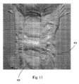
図10〜13を参照すると、立体的な液体透過性基材400(本明細書では、立体的基材又は液体透過性基材と呼ぶ)が、吸収性物品402上に示されている。図10は、着用者側表面が観測者に面した吸収性物品402の平面図である。図11は、着用者側表面が観測者に面した吸収性物品402の斜視図である。図12は、着用者側表面が観測者に面した吸収性物品上の液体透過性基材400の一部の平面図である。図13は、着用者側表面が観測者に面した吸収性物品402上の液体透過性基材400の一部の別の平面図である。
With reference to FIGS. 10-13, a three dimensional liquid permeable substrate 400 (referred to herein as a three dimensional substrate or a liquid permeable substrate) is shown on an
1つの形態では、液体透過性基材400又は本明細書に述べられる他の液体透過性基材は、吸収性物品402のトップシート上に配置されるかかつ/又はトップシートに接合されたパッチ又はストリップを含みうる。パッチ又はストリップは、トップシートに結合するか、接着剤によってトップシートに接着するか、トップシートに常温圧接するか、トップシートに超音波接合するか、かつ/又は他の形でトップシートに接合することができる。あるいは、本開示の液体透過性基材は、トップシート(例えばトップシート24)を含むか、トップシートの全体を形成するか、又はトップシートの一部を形成することがきる。また、トップシート24は、1つ以上の本開示の液体透過性基材のみで構成されてもよい。異なる構成のいずれにおいても、本開示の液体透過性基材は、吸収性物品の着用者側表面の少なくとも一部を形成し、着用者の皮膚と少なくとも部分的に接触することを意図している。
In one form, the liquid
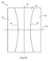
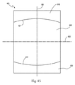
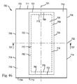
図14〜16を参照すると、パッチ又はストリップの形態でトップシート24に接合された液体透過性基材400又は本明細書に述べられる他の液体透過性基材は、機械横断方向の幅W1を有してよく、一方、トップシート24は機械横断方向の幅W2を有してよい。W1は、幅W2よりも小さいか、これと同じであるか、これとほぼ同じであるか、又はこれよりも大きくてよい(図示せず)。幅W1は、液体透過性基材の長手方向の長さ全体にわたって変化しても一定であってもよい。引き続き図14〜16を参照すると、パッチ又はストリップの形態の液体透過性基材400又は本明細書に述べられる他の液体透過性基材は機械方向の長さL1を有してよく、一方、トップシート24は機械方向の長さL2を有することができる。L1は、長さL2よりも小さいか、これと同じであるか、これとほぼ同じであるか、又はこれよりも大きくてよい(図示せず)。長さL1は、液体透過性基材の幅W1全体にわたって変化しても一定であってもよい。図14〜16には示されていないが、トップシート24及び液体透過性基材の長さと幅は、同じか又はほぼ同じであってもよい。
14-16, a liquid
液体透過性基材400のパッチ又はストリップは図14〜16では長方形のものとして示されているが、本開示の液体透過性基材は、前方/後方に輪郭形成された形状(すなわち前方により広い、後方により広い、及び/又は股部でより狭い)、正方形、卵形、又は他の適当な形状などの他の任意の適当な形状を有してもよい。液体透過性基材400の側縁部404及び/又は端縁部406は、液体透過性基材400に美的に好ましい外観を与えるために1つ以上の円弧状部分、設計、及び/又は形状がそこから切り取られてもよい。一方の側縁部404は、トップシート24の長手方向軸408を中心として他方の側縁部404と対称又は非対称であってよい。同様に、一方の端縁部406は、トップシート24の横方向軸410を中心として他方の側縁部406と対称又は非対称であってよい。
Although the patches or strips of the liquid
液体透過性基材400は1つ以上の層を有することができる。複数の層が設けられる場合、各層同士は、機械的結合、接着剤による結合、圧力結合、熱結合、両方の層を通じて加熱空気を流すこと、又は他の接合方法によって互いに接合されるか、又は互いに接着されることで多層基材400を形成する。あるいは、層は、第1の種類及び第2の種類のステープル繊維に対して第1及び第2のカーディング操作、又は添加剤を含むスパンボンド積層ポリマーフィラメントの2つの連続したビームなどの連続した繊維堆積工程で形成されてもよい。第1の層を1つ以上の疎水性材料で構成するか、又は完全に疎水性とすることができ、第2の層を1つ以上の親水性材料で構成するか又は完全に親水性とすることができる。一方の層を疎水性材料で構成し、他方の層を親水性材料で構成する代わりに、一方の層を他方の層を構成する材料よりも疎水性又は親水性が高い材料で構成してもよい(例えば両方の層が親水性であるが一方の層の親水性がより高いか、又は両方の層が疎水性であるが一方の層の疎水性がより高い)。第1の層を疎水性層として構成し、第2の層を親水性層として構成するか、又はその逆とすることができる。第1の層を、吸収性物品の着用者側表面の一部又は全体として用いることができる。あるいは、第2の層を、吸収性物品の着用者側表面の一部又は全体として用いることもできる。
The liquid
第1の層(又は着用者側の層)を疎水性材料で構成する理由は2つある。第1に、液体透過性基材に開口部が形成される場合、疎水性層は親水性の第2の層ほど多くの液体を保持しないため、着用者の皮膚と直接接触する液体(例えば尿)が少なくなることである。第2に、第1及び第2の層の突起部(後述する)が、液体透過性基材の着衣側の面にADS又はコアと直接接触しない中空部分又はアーチを概ね形成することによって、液体が中空のアーチ内に捕捉されることである。ADS又はコアへの中空のアーチの良好な接続性がなければ、液体透過性基材がより多くの液体を保持して、着用者に濡れて感じられる可能性がある。しかしながら、疎水性の第1の層が設けられることにより、中空のアーチ内に吸い上げられた液体は大部分が衣類側の、又は液体透過性基材下向きの親水性面上に存在することになるため、第1の疎水性層はより乾燥した状態に保たれる。原理的には、これは、第1の層から第2の層に向かう親水性又は毛管勾配によって実現することができる(例えば第2の層内の同じ親水性(すなわち液体との接触角)を有するより微細な繊維により)。基材の開口部は、第1の疎水性層の存在にもかかわらず、初期の速やかな液体の流れ(裏抜け)を可能とする重要な役割を担うことができる。したがって、第1の疎水性層は、突起部、中空のアーチ、及び開口部と協働して、液体透過性基材の着用者側表面上の濡れ感を低減する。他の場合では、第2の層を着用者側表面の一部として用いることができる。 There are two reasons for configuring the first layer (or the wearer side layer) with a hydrophobic material. First, when an opening is formed in a liquid permeable substrate, the hydrophobic layer does not hold as much liquid as the hydrophilic second layer, so that the liquid that is in direct contact with the wearer's skin (eg, urine) ) Is less. Second, the protrusions (described later) of the first and second layers generally form a hollow portion or arch that does not directly contact the ADS or the core on the clothing-side surface of the liquid-permeable substrate. Is trapped in the hollow arch. Without the good connectivity of the hollow arch to the ADS or core, the liquid permeable substrate may hold more liquid and feel wet by the wearer. However, due to the provision of the hydrophobic first layer, the liquid sucked into the hollow arch will be mostly present on the hydrophilic side of the garment side or downward of the liquid permeable substrate. Therefore, the first hydrophobic layer is kept in a drier state. In principle, this can be achieved by a hydrophilic or capillary gradient from the first layer to the second layer (eg the same hydrophilicity in the second layer (ie the contact angle with the liquid)). Having finer fibers). The opening of the substrate can play an important role that allows an initial rapid liquid flow (back through) despite the presence of the first hydrophobic layer. Thus, the first hydrophobic layer cooperates with the protrusions, the hollow arch, and the opening to reduce the wet feeling on the wearer side surface of the liquid permeable substrate. In other cases, the second layer can be used as part of the wearer side surface.
第1の層は、複数の第1の繊維及び/又はフィラメント(以下、まとめて繊維と呼ぶ)で構成することができる。複数の第1の繊維は、サイズ、形状、組成、デニール、繊維直径、繊維長さ、及び/又は重量が同じか、ほぼ同じか、又は異なる繊維で構成されうる。第2の層は、複数の第2の繊維で構成されうる。複数の第2の繊維は、サイズ、形状、組成、デニール、繊維直径、繊維長さ、及び/又は重量が同じか、ほぼ同じか、又は異なる繊維で構成されうる。複数の第1の繊維は、複数の第2の繊維と同じか、ほぼ同じか、又は異なっていてよい。更なる層は、同じか又は異なる構成を有してよい。 The first layer can be composed of a plurality of first fibers and / or filaments (hereinafter collectively referred to as fibers). The plurality of first fibers can be composed of fibers that are the same, approximately the same, or different in size, shape, composition, denier, fiber diameter, fiber length, and / or weight. The second layer can be composed of a plurality of second fibers. The plurality of second fibers can be composed of fibers that are the same, approximately the same, or different in size, shape, composition, denier, fiber diameter, fiber length, and / or weight. The plurality of first fibers may be the same as, substantially the same as, or different from the plurality of second fibers. Further layers may have the same or different configurations.
第1の層及び/又は第2の層は、シースとコアを有する2成分繊維を構成することができる。シースはポリエチレンで構成し、コアはポリマーエチレンテレフタラート(PET)で構成することができる。シース及びコアは、当業者には周知の他の任意の適当な材料で構成してもよい。シース及びコアは、繊維の重量にして繊維の約50重量%をそれぞれ構成してよいが、他の変例(例えばシース60%とコア40%、シース30%とコア70%など)も本開示の範囲内である。第1及び/又は第2の層を構成する2成分繊維又は他の繊維は、約0.5〜約4、約1.0〜約3、約1.5〜約2.5、又は約2の範囲内のデニール、詳細には、指定された範囲内、及びこれらの範囲内又はこれらの範囲によって形成されるすべての範囲内のすべての0.1デニール刻みの値を有することができる。デニールは、繊維長さ900m当りのグラム数で表した質量として定義される。 The first layer and / or the second layer can constitute a bicomponent fiber having a sheath and a core. The sheath can be composed of polyethylene and the core can be composed of polymer ethylene terephthalate (PET). The sheath and core may be composed of any other suitable material known to those skilled in the art. The sheath and core may each constitute approximately 50% by weight of the fiber, but other variations (eg, 60% sheath and 40% core, 30% sheath and 70% core, etc.) are also disclosed herein. Is within the range. The bicomponent fibers or other fibers that make up the first and / or second layer may be from about 0.5 to about 4, from about 1.0 to about 3, from about 1.5 to about 2.5, or from about 2 Can have a value of every 0.1 denier in the specified range, and in particular within the specified range, and within all ranges formed by or within these ranges. Denier is defined as the mass expressed in grams per 900 meters of fiber length.
複数の第1及び第2の繊維は、例えばポリプロピレン繊維、他のポリオレフィン、ポリ乳酸などのPET以外の他のポリエステル、熱可塑性デンプン含有持続可能樹脂、他の持続可能樹脂、バイオPE、バイオPP及びバイオPET、ビスコース繊維、レーヨン繊維、又は他の適当な不織布繊維などの他の任意の適当な種類の繊維も含むことができる。これらの繊維は、任意の適当なデニール若しくはデニールの範囲、及び/又は繊維長さ若しくは繊維長さの範囲を有することができる。複数の第1及び第2の繊維が同じか又はほぼ同じである場合では、複数の第2の繊維を、界面活性剤などの親水化剤で処理することによって、複数の第2の繊維を親水化するか又は少なくとも疎水性を低下させることができる。複数の第1の繊維は、その自然の疎水性状態を保つように界面活性剤で処理せずともよく、又は複数の第1の繊維を界面活性剤で処理することによって疎水性を低めてもよい。 The plurality of first and second fibers include, for example, polypropylene fibers, other polyolefins, other polyesters other than PET such as polylactic acid, thermoplastic starch-containing sustainable resins, other sustainable resins, bio PE, bio PP, and Any other suitable type of fiber such as bioPET, viscose fiber, rayon fiber, or other suitable nonwoven fiber may also be included. These fibers can have any suitable denier or denier range and / or fiber length or fiber length range. In the case where the plurality of first and second fibers are the same or substantially the same, the plurality of second fibers are made hydrophilic by treating the plurality of second fibers with a hydrophilizing agent such as a surfactant. Or at least reduce hydrophobicity. The plurality of first fibers may not be treated with a surfactant so as to maintain their natural hydrophobic state, or the plurality of first fibers may be made hydrophobic by treating them with a surfactant. Good.
第1の層は、約10gsm〜約25gsmの範囲の坪量を有することができる。第2の層は、約10gsm〜約45gsmの範囲の坪量を有することができる。基材(第1及び第2の層の両方)の坪量は、約20gsm〜約70gsm、約20gsm〜約60gsm、約25gsm〜約50gsm、約30gsm〜約40gsm、約30gsm、約35gsm、又は約40gsmの範囲であってよい。 The first layer can have a basis weight in the range of about 10 gsm to about 25 gsm. The second layer can have a basis weight in the range of about 10 gsm to about 45 gsm. The basis weight of the substrate (both first and second layers) is about 20 gsm to about 70 gsm, about 20 gsm to about 60 gsm, about 25 gsm to about 50 gsm, about 30 gsm to about 40 gsm, about 30 gsm, about 35 gsm, or about It may be in the range of 40 gsm.
1つの例では、基材の坪量は、約30gsm〜約40gsm又は約35gsmであってよい。かかる例では、第1の層は、約10gsm〜約20gsm、又は約15gsmの範囲の坪量を有してよく、第2の層は、約15gsm〜約25gsm、又は約20gsmの範囲の坪量を有してよい。別の例では、基材の坪量は約20gsmであってよい。かかる例では、第1の層は約10gsmの坪量を有してよく、第2の層は約10gsmの坪量を有してよい。更に別の例では、基材の坪量は約60gsmであってよい。かかる例では、第1の層は約24gsmの坪量を有してよく、第2の層は36gsmの坪量を有してよい。第1及び第2の層及び基材の他のすべての適当な坪量の範囲は、本開示の範囲内である。したがって、層及び基材の坪量は、特定の製品の要求条件に合わせて設計することができる。 In one example, the basis weight of the substrate can be from about 30 gsm to about 40 gsm or about 35 gsm. In such examples, the first layer may have a basis weight in the range of about 10 gsm to about 20 gsm, or about 15 gsm, and the second layer may have a basis weight in the range of about 15 gsm to about 25 gsm, or about 20 gsm. May be included. In another example, the basis weight of the substrate can be about 20 gsm. In such an example, the first layer may have a basis weight of about 10 gsm and the second layer may have a basis weight of about 10 gsm. In yet another example, the basis weight of the substrate may be about 60 gsm. In such an example, the first layer may have a basis weight of about 24 gsm and the second layer may have a basis weight of 36 gsm. All other suitable basis weight ranges for the first and second layers and substrates are within the scope of this disclosure. Thus, the basis weight of the layer and substrate can be designed to meet the requirements of a particular product.
上記に指定した坪量の範囲及びこれらの範囲内又はこれらの範囲によって形成されるすべての範囲内のすべての0.1gsm刻みの値を本明細書に詳細に記載する。 The basis weight ranges specified above and all 0.1 gsm values within these ranges or within all ranges formed by these ranges are described in detail herein.
本開示の液体透過性基材は、バックシート25の少なくとも一部に接合される外側カバー23の一部又は全体を形成してもよい。他の場合では、外側カバー23は、本開示の液体透過性基材と同じ又は同様の外見を有するあるパターン(例えばエンボス加工パターン、印刷パターン)及び/又は立体構造を有することができる。一般的に、着用者側表面上の液体透過性基材の少なくとも一部の外見は、外側カバー23の少なくとも一部又は吸収性物品の別の部分と一致するか又はほぼ一致してよい。
The liquid permeable substrate of the present disclosure may form a part or the whole of the outer cover 23 joined to at least a part of the
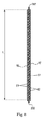
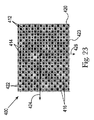
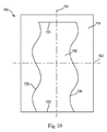
図17は、着用者側表面が観測者に面した、立体的な液体透過性基材の一部の正面図である。図18は、図17の立体的な液体透過性基材の一部の正面斜視図である。図19は、着用者側表面が観測者に面した、立体的な液体透過性基材の一部の別の正面図である。図20は、図19の液体透過性基材の一部の正面斜視図である。図21は、着用者側表面が観測者に面した、立体的な液体透過性基材の一部の背面図である。図22は、図21の立体的な液体透過性基材の一部の背面斜視図である。図23は、着用者側表面が観測者に面した、立体的な液体透過性基材の一部の別の背面図である。図24は、図23の液体透過性基材の一部の背面斜視図である。図25は、液体透過性基材の断面図である。 FIG. 17 is a front view of a part of a three-dimensional liquid-permeable substrate with the wearer-side surface facing the observer. FIG. 18 is a front perspective view of a part of the three-dimensional liquid-permeable substrate of FIG. FIG. 19 is another front view of a part of a three-dimensional liquid-permeable substrate with the wearer-side surface facing the observer. FIG. 20 is a front perspective view of a part of the liquid-permeable substrate of FIG. FIG. 21 is a rear view of a part of a three-dimensional liquid-permeable substrate with the wearer-side surface facing the observer. 22 is a rear perspective view of a part of the three-dimensional liquid-permeable substrate of FIG. FIG. 23 is another back view of a portion of the three-dimensional liquid permeable substrate with the wearer side surface facing the observer. 24 is a rear perspective view of a part of the liquid-permeable substrate of FIG. FIG. 25 is a cross-sectional view of a liquid permeable substrate.
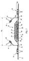
図17〜25を大まかに参照すると、液体透過性基材400は、第1の層及び第2の層で、又は2つよりも多い層若しくは1つの層で構成することができる。基材400は、複数のランド区域412、複数の凹部414、及び複数の突起部416を含みうる。上記に述べたように、複数の突起部416は第1のz方向の高さを有する第1の要素を形成し、ランド区域412は第2のz方向の高さを有する第2の要素を形成することができる。複数のランド区域412、複数の凹部414、及び複数の突起部416はともに、基材400の第1の面418上に第1の立体的表面を形成することができる。複数のランド区域412、複数の凹部414、及び複数の突起部416はまた、基材400の第2の面420上に第2の立体的表面も形成することができる。突起部416は、液体透過性基材400の着用者側表面上では概ねドーム形状であってよく、基材400の衣類側表面上では中空のアーチ形状であってよい。凹部414のすべてのもの、又は大部分(すなわち50%よりも多く、又は75%よりも多く)、又はほぼすべてのものは、隣接する突起部416の頂部ピーク425から最も遠い位置に開口部422を画定することができる。大部分又はすべての開口部422の外周423が、基材400の最下部又は平面を形成しうる一方で、大部分又はすべての突起部416の頂部ピーク425(すなわち最上部)は、基材400の最上部又は平面を形成することができる。他の場合では、基材は凹部414内に開口部を有さずともよく、突起部416の頂部ピーク425から最も遠い凹部414の部分が、基材400の最下部又は平面を形成してもよい。開口部422は、基材400の第1及び第2の層を貫通して延びることができる。
Referring generally to FIGS. 17-25, the liquid
ランド区域412は、(1)隣り合った突起部416、(2)隣り合った凹部414、及び/又は隣り合った開口部422の中間に配置することができる。ランド区域412は、大部分又はすべての凹部414及び/又は開口部、及び少なくとも大部分又はすべての突起部416の少なくとも一部又は全体を包囲してもよい。ランド区域412は、少なくとも大部分の開口部422の外周の平面と、少なくとも大部分の突起部416の頂部ピーク425の平面との間に配置することができる。
The
突起部416は、液体透過性基材400の横方向軸424とほぼ平行な方向に凹部414及び/又は開口部422と交互に位置することができる。横方向軸424は、図14〜16に示される横方向軸410とほぼ平行である。突起部416は、液体透過性基材400の長手方向軸426とほぼ平行な方向に凹部414及び/又は開口部422と交互に位置することもできる。長手方向軸426は、図14〜16に示される長手方向軸408とほぼ平行である。このような構成では、横方向軸424とほぼ平行な方向、又は長手方向軸426とほぼ平行な方向に、突起部416と凹部414及び/又は開口部422とが交互に位置する(すなわち、突起部、凹部及び/又は開口部、突起部、凹部及び/又は開口部)。この構成は、大部分又はすべての隣り合う凹部414及び/又は開口部422の中間に軟らかい突起部ピーク425が存在する点で、基材400により高い柔軟性を与えるものである。この構成は、突起部416が皮膚と液体との間のスペーサーを基本的に形成することから、ランド区域412及び/又は凹部414内において着用者の皮膚を液体から遠ざけた状態に維持する助けとなるものである。
The
2個以上の隣り合った突起部416は、横方向軸424にほぼ平行な方向、又は長手方向軸426にほぼ平行な方向に、凹部414及び/又は開口部422及び1つ以上のランド区域412によって互いから分離されうる。2個以上の隣り合った凹部414及び/又は開口部422は、横方向軸424にほぼ平行な方向、又は長手方向軸426にほぼ平行な方向に、突起部416及び1つ以上のランド区域412によって分離されうる。ランド区域412は、開口部422及び突起部416を完全に包囲してもよい。ランド区域412はともに、基材400全体にわたって概ね連続的な格子を形成してよく、一方、突起部416及び凹部414及び/又は開口部422は、基材全体にわたって個別の要素であってよい。
Two or more
いくつかの場合では、2個以上、例えば4個の突起部416を、少なくとも大部分、ほぼすべて、又はすべての凹部414及び/又は開口部422の周囲に配置することができる(これは、突起部416及び凹部414及び/又は開口部422の中間のランド区域412を含まない)。2個以上、例えば4個の凹部414及び/又は開口部422を、少なくとも大部分、ほぼすべて、又はすべての突起部416の周囲に配置することもできる(これは、凹部414及び/又は開口部422及び突起部416の中間のランド区域412を含まない)。突起部416、凹部414、開口部422、及びランド区域422はいずれも、基材の第1及び第2の層の一部で形成することができる。2つよりも多い層が基材に設けられる場合には、突起部416、凹部414、開口部422、及びランド区域422はいずれも、基材の第1、第2、及び第3の層の一部で形成することができる。同じことが、特定の基材に3つよりも多い層が設けられる場合にも当てはまりうる。他の場合では、ランド区域422は、第1の層にのみ形成されてもよい。
In some cases, two or more, eg, four
開口部422及び/又は凹部414は、ともに基材400に第1の線を形成する第1の群の開口部及び/又は凹部414、並びにともに基材400に第2の線を形成する第2の群開口部422及び/又は凹部414を含むことができる。第1の線は、第2の線と概ね平行であるか又は概ね垂直であってよい。第1の線は、第2の線と鋭角又は鈍角をなしてもよい。突起部416は、ともに基材400に第1の線を形成する第1の群の突起部416、並びにともに基材400に第2の線を形成する第2の群の突起部416を含むことができる。第1の線は、第2の線と概ね平行であるか又は概ね垂直であってよい。第1の線は、第2の線と鋭角又は鈍角をなしてもよい。
The
基材400は、横方向軸424を中心として概ね対称的であってよく、かつ/又は長手方向軸426を中心として概ね対称的であってもよい。他の場合では、基材は、横方向軸424及び/又は長手方向軸426を中心として対称的でなくともよい。
The
1つの形態では、基材400は、横方向軸424と平行な方向に延びる、交互に位置する開口部422及び突起部416からなる第1の線と、横方向軸424と概ね平行な方向に延びる、交互に位置する開口部422及び突起部416からなる第2の隣接する線とを有することができる。これらの線は、開口部422及び突起部416の中心を通って延びる。例えば図17の線A及びBを参照されたい。長手方向軸426と概ね平行な方向であり、線A及びBと交差する線Cが引かれる場合、線Aと線Cとの交点には開口部422が位置し、線Bと線Cとの交点には突起部416が位置することになる。図18に示されるように、線A及びBが長手方向軸426と平行な方向に引かれ、線Cが横方向軸424と概ね平行な方向に引かれる場合にも同じことが言える。線が異なる位置に引かれる場合には、線Aと線Cとの交点が突起部416を有し、線Bと線Cとの交点が開口部422を有してもよい。重要な点は、開口部の列と突起部の列とがずれて配置されているということである。開口部と突起部とがこのようにずれて配置されることにより、2個の開口部の中間に軟らかい突起部又は突起部の頂点が位置することにより、基材400の着用者側表面においてより良好な軟らかさが得られる。
In one form, the
立体的基材のパラメータ
突起部416のすべて又は大部分のものは、約300μm〜約6000μm、約500μm〜約5000μm、約500μm〜約4000μm、約300μm〜約3000μm、約500μm〜約3000μm、約500μm〜約2000μm、約750μm〜約1500μm、約800μm〜約1400μm、約900μm〜約1300μm、約1000μm〜約1300μm、約1100μm〜約1200μm、約1165、約1166、約1167、又は約1150μm〜約1200μmの範囲のz方向の高さを有してよく、詳細には上記に指定される範囲内、及びこれらの範囲内又はこれらの範囲によって形成されるすべての範囲内のすべての1μm刻みの値を記載する。突起部416のz方向の高さは、本明細書に述べられる突起部の高さ試験に従って測定されるものである。
Three-dimensional substrate parameters All or most of the
凹部414のすべて又は大部分のものは、約200μm〜約3000μm、約300μm〜約2000μm、約100μm〜約2000μm、約500μm〜約2000μm、約500μm〜約1500μm、約700μm〜約1300μm、約800μm〜約1200μm、約900μm〜約1100μm、約900μm〜約1000μm、約970μm、又は約950μm〜約1000μmの範囲のz方向の高さを有してよく、詳細には上記に指定される範囲内、及びこれらの範囲内又はこれらの範囲によって形成されるすべての範囲内のすべての1μm刻みの値を記載する。凹部416のz方向の高さは、本明細書に述べられる凹部の高さ試験に従って測定されるものである。
All or most of the
基材400又はその一部は、約500μm〜約6000μm、約750μm〜約4000μm、約1000μm〜約6000μm、約1500μm〜約6000μm、約1000μm〜約3000μm、約1500μm〜約2500μm、約1750μm〜約2300μm、約1900μm〜約2300μm、約2000μm〜約2300μm、約2100μm〜約2250μm、約2136μm、又は約2135μmの範囲の全体のz方向の高さを有してよく、詳細には上記に指定される範囲内、及びこれらの範囲内又はこれらの範囲によって形成されるすべての範囲内のすべての1μm刻みの値を記載する。基材400又はその一部の全体のz方向の高さは、本明細書に述べられる全体の基材の高さ試験に従って測定されるものである。
The
開口部422の大部分又はすべてのものは、約0.4mm2〜約10mm2、約0.5mm2〜約8mm2、約0.5mm2〜約3mm2、約0.5mm2〜約4mm2、約0.5mm2〜約5mm2、約0.7mm2〜約6mm2、約0.7mm2〜約3mm2、約0.8mm2〜約2mm2、約0.9mm2〜約1.4mm2、約1mm2、約1.1mm2、約1.2mm2、約1.23mm2、約1.3mm2、又は約1.4mm2の範囲の有効開口部面積を有してよく、詳細には上記に指定される範囲内、及びこれらの範囲内又はこれらの範囲によって形成されるすべての範囲内のすべての0.1mm2刻みの値を記載する。開口部の有効開口部面積は、本明細書に述べられる開口部試験に従って測定されるものである。
Most or all of the
開口部422の大部分又はすべてのものは、約0.5mm〜約4mm、約0.8mm〜約3mm、約1mm〜約2mm、約1.2mm〜約1.8mm、約1.4mm〜約1.6mm、約1.49、又は約1.5mmの範囲のフェレー径(開口部の長さ)を有してよく、詳細には上記に指定される範囲内、及びこれらの範囲内又はこれらの範囲によって形成されるすべての範囲内のすべての0.1mm刻みの値を記載する。開口部のフェレー径は、本明細書に述べられる開口部試験に従って測定されるものである。
Most or all of the
開口部422の大部分又はすべてのものは、約0.5mm〜約4mm、約0.7mm〜約3mm、約0.8mm〜約2mm、約0.9mm〜約1.3mm、約1mm〜約1.2mm、約1mm、約1.1mm、約1.11mm、約1.2mm、又は約1.3mmの範囲の最小フェレー径(開口部の幅)を有してよく、詳細には上記に指定される範囲内、及びこれらの範囲内又はこれらの範囲によって形成されるすべての範囲内のすべての0.1mm刻みの値を記載する。開口部の最小のフェレー径は、本明細書に述べられる開口部試験に従って測定されるものである。
Most or all of the
開口部422の大部分又はすべてのものは、約0.3〜約2.5、約0.5〜約2、約0.8〜約1.6、約1〜約1.5、約1.1〜約1.5、約1.2、約1.3、約1.35、約1.4、又は約1.5の範囲の最小フェレー径に対するフェレー径の比を有してよく、詳細には上記に指定される範囲内、及びこれらの範囲内又はこれらの範囲によって形成されるすべての範囲内のすべての0.1刻みの値を記載する。かかるフェレー径の比は、開口部のフェレー径を開口部の最小フェレー径で割ることによって計算される。
Most or all of the
大部分又はすべての隣り合う開口部の、突起部にわたって測定した平均の横方向軸に沿った中心間の開口部間隔は、約2mm〜約20mm、約2mm〜約15mm、約3mm〜約12mm、約3mm〜約10mm、約3mm〜約8mm、約3mm〜約7mm、約4mm〜約6mm、約5mm〜約6mm、約4mm、約4.8mm、約4.9mm、約5.0mm、約5.1mm、約5.2mm、約5.3mm、約5.4mm、約5.5mm、約5.6mm、約5.7mm、約5.8mm、又は約5.9mm、約6mm、約7mm、約8mm、約9mm、又は約10mmの範囲であってよく、詳細には上記に指定される範囲内、及びこれらの範囲内又はこれらの範囲によって形成されるすべての範囲内のすべての0.1mm刻みの値を記載する。隣り合う開口部の平均の横方向軸に沿った中心間の開口部間隔は、本明細書に述べられる平均開口部間隔試験(横方向軸開口部間隔)に従って測定されるものである。 The center-to-center opening spacing along the average transverse axis, measured across the protrusion, of most or all adjacent openings is about 2 mm to about 20 mm, about 2 mm to about 15 mm, about 3 mm to about 12 mm, About 3 mm to about 10 mm, about 3 mm to about 8 mm, about 3 mm to about 7 mm, about 4 mm to about 6 mm, about 5 mm to about 6 mm, about 4 mm, about 4.8 mm, about 4.9 mm, about 5.0 mm, about 5 0.1 mm, about 5.2 mm, about 5.3 mm, about 5.4 mm, about 5.5 mm, about 5.6 mm, about 5.7 mm, about 5.8 mm, or about 5.9 mm, about 6 mm, about 7 mm, It may be in the range of about 8 mm, about 9 mm, or about 10 mm, in particular all 0.1 mm within the ranges specified above, and within these ranges or all ranges formed by these ranges. Enter the step value. The center-to-center aperture spacing along the average lateral axis of adjacent apertures is measured according to the average aperture spacing test (lateral axis aperture spacing) described herein.
大部分又はすべての隣り合う開口部の、突起部にわたって測定した平均の長手方向軸に沿った中心間の開口部間隔は、約2mm〜約20mm、約2mm〜約15mm、約3mm〜約12mm、約3mm〜約10mm、約3mm〜約8mm、約3mm〜約7mm、約4mm〜約6mm、約5mm〜約6mm、約4mm、約4.8mm、約4.9mm、約5.0mm、約5.1mm、約5.2mm、約5.3mm、約5.4mm、約5.5mm、約5.6mm、約5.7mm、約5.8mm、又は約5.9mm、約6mm、約7mm、約8mm、約9mm、又は約10mmの範囲であってよく、詳細には上記に指定される範囲内、及びこれらの範囲内又はこれらの範囲によって形成されるすべての範囲内のすべての0.1mm刻みの値を記載する。隣り合う開口部の平均の長手方向軸に沿った中心間の開口部間隔は、本明細書に述べられる平均開口部間隔試験(長手方向軸開口部間隔)に従って測定されるものである。 The center-to-center opening spacing along the average longitudinal axis, measured across the protrusion, of most or all adjacent openings is about 2 mm to about 20 mm, about 2 mm to about 15 mm, about 3 mm to about 12 mm, About 3 mm to about 10 mm, about 3 mm to about 8 mm, about 3 mm to about 7 mm, about 4 mm to about 6 mm, about 5 mm to about 6 mm, about 4 mm, about 4.8 mm, about 4.9 mm, about 5.0 mm, about 5 0.1 mm, about 5.2 mm, about 5.3 mm, about 5.4 mm, about 5.5 mm, about 5.6 mm, about 5.7 mm, about 5.8 mm, or about 5.9 mm, about 6 mm, about 7 mm, It may be in the range of about 8 mm, about 9 mm, or about 10 mm, in particular all 0.1 mm within the ranges specified above, and within these ranges or all ranges formed by these ranges. Enter the step valueThe center-to-center aperture spacing along the average longitudinal axis of adjacent apertures is measured according to the average aperture spacing test (longitudinal axis aperture spacing) described herein.
突起部416の大部分又はすべてのものは、約1〜約15mm、約1mm〜約10mm、約1mm〜約8mm、約1mm〜約6mm、約1.5mm〜約6mm、約2mm〜約5mmの範囲の、吸収性物品の横方向軸に平行な方向に測定した、最も幅の広い断面直径を有してよく、詳細には上記に指定される範囲内、及びこれらの範囲内又はこれらの範囲によって形成されるすべての範囲内のすべての0.1mm刻みの値を記載する。
Most or all of the
突起部416の大部分又はすべてのものは、約1〜約15mm、約1mm〜約10mm、約1mm〜約8mm、約1mm〜約6mm、約1.5mm〜約6mm、約2mm〜約5mmの範囲の、吸収性物品の長手方向軸に平行な方向に測定した、最も幅の広い断面直径を有してよく、詳細には上記に指定される範囲内、及びこれらの範囲内又はこれらの範囲によって形成されるすべての範囲内のすべての0.1mm刻みの値を記載する。
Most or all of the
本開示の基材は、約1%〜約50%、約1%〜約40%、約3%〜約35%、約5%〜約25%、約5%〜約20%、約6%〜約18%、約5%〜約15%、約5%、約8%、約9%、約9.5%、約10%、約10.5%、約11%、又は約12%の範囲の有効開放面積率(%)を有してよく、詳細には上記に指定される範囲内、及びこれらの範囲内又はこれらの範囲によって形成されるすべての範囲内のすべての0.1%刻みの値を記載する。基材の有効開放面積率(%)は、本明細書に述べられる開口部試験に従って測定されるものである。 The substrates of the present disclosure can be from about 1% to about 50%, from about 1% to about 40%, from about 3% to about 35%, from about 5% to about 25%, from about 5% to about 20%, about 6% About 18%, about 5% to about 15%, about 5%, about 8%, about 9%, about 9.5%, about 10%, about 10.5%, about 11%, or about 12% May have an effective open area percentage (%) of the range, in particular all 0.1% within the ranges specified above and within these ranges or all ranges formed by these ranges Enter the step value. The effective open area percentage (%) of the substrate is measured according to the opening test described herein.
本開示の基材は、約1mm〜約50mm、約1mm〜約30mm、約2mm〜約20mm、約2mm〜約15mm、約2mm〜約10mm、約3mm〜約8mm、約4mm、約5mm、約5.42mm、約6mm、又は約7mmの範囲の外周を有する開口部を有してよく、詳細には上記に指定される範囲内、及びこれらの範囲内又はこれらの範囲によって形成されるすべての範囲内のすべての0.1mm刻みの値を記載する。開口部の外周は、本明細書に述べられる開口部試験に従って測定されるものである。 The substrate of the present disclosure can be about 1 mm to about 50 mm, about 1 mm to about 30 mm, about 2 mm to about 20 mm, about 2 mm to about 15 mm, about 2 mm to about 10 mm, about 3 mm to about 8 mm, about 4 mm, about 5 mm, about It may have openings having a perimeter in the range of 5.42 mm, about 6 mm, or about 7 mm, in particular within the ranges specified above, and all formed by or within these ranges. List all values in 0.1mm increments within the range. The outer periphery of the opening is measured according to the opening test described herein.
本開示の基材400の第1の面418は、約2〜約4.5、約2.5〜約4、約3〜約4、約3.1〜約3.5、約3.2、約3.3、約3.31、約3.35、約3.4、又は約3.5の範囲の幾何学的粗度値を有してよく、詳細には上記に指定される範囲内、及びこれらの範囲内又はこれらの範囲によって形成されるすべての範囲内のすべての0.1刻みの値を記載する。本開示の基材400の第1の面418の幾何学的粗度値は、本明細書に述べられる記述的分析粗度試験に従って測定されるものである。本開示の基材400の第1の面418は、約0.2〜約0.4、約0.25〜約0.35、約0.27〜約0.31、約0.27、約0.28、約0.29、約0.30、又は約0.31の範囲の摩擦係数の値を有してよく、詳細には上記に指定される範囲内、及びこれらの範囲内又はこれらの範囲によって形成されるすべての範囲内のすべての0.01刻みの値を記載する。本開示の基材400の第1の面418の摩擦係数の値は、本明細書に述べられる記述的分析粗度試験に従って測定されるものである。本開示の基材400の第1の面418は、約0.010〜約0.025、約0.015〜約0.020、約0.015、約0.016、約0.017、約0.018、又は約0.019の範囲のスリップスティック値を有してよく、詳細には上記に指定される範囲内、及びこれらの範囲内又はこれらの範囲によって形成されるすべての範囲内のすべての0.001刻みの値を記載する。本開示の基材400の第1の面418の摩擦係数の値は、本明細書に述べられる記述的分析粗度試験に従って測定されるものである。
The
本開示の基材400の第2の面420は、約2〜約4.0、約2.3〜約3.5、約2.5〜約3.3、約2.6〜約3.1、約2.6、約2.7、約2.8、約2.83、約2.9、又は約3.0の範囲の幾何学的粗度値を有してよく、詳細には上記に指定される範囲内、及びこれらの範囲内又はこれらの範囲によって形成されるすべての範囲内のすべての0.1刻みの値を記載する。本開示の基材400の第2の面420の幾何学的粗度値は、本明細書に述べられる記述的分析粗度試験に従って測定されるものである。本開示の基材400の第2の面420は、約0.2〜約0.4、約0.25〜約0.35、約0.27〜約0.31、約0.27、約0.28、約0.29、約0.30、又は約0.31の範囲の摩擦係数の値を有してよく、詳細には上記に指定される範囲内、及びこれらの範囲内又はこれらの範囲によって形成されるすべての範囲内のすべての0.01刻みの値を記載する。本開示の基材400の第2の面420の摩擦係数の値は、本明細書に述べられる記述的分析粗度試験に従って測定されるものである。本開示の基材400の第2の面420は、約0.010〜約0.025、約0.011〜約0.018、約0.012、約0.013、約0.014、約0.015、又は約0.016の範囲のスリップスティック値を有してよく、詳細には上記に指定される範囲内、及びこれらの範囲内又はこれらの範囲によって形成されるすべての範囲内のすべての0.001刻みの値を記載する。本開示の基材400の第2の面420の摩擦係数の値は、本明細書に述べられる記述的分析粗度試験に従って測定されるものである。
The
比
有効開放面積率(%)に対する突起部の高さ(μm)の比は、約70〜約160、約80〜約150、約100〜約145、約95〜約150、約100〜約140、約110〜約130、約115〜約130、約118〜約125、約120、約121、約122、約122.74、約123、又は約124の範囲であってよく、詳細には上記に指定される範囲内、及びこれらの範囲内又はこれらの範囲によって形成されるすべての範囲内のすべての0.1刻みの値を記載する。
The ratio of the protrusion height (μm) to the effective open area ratio (%) is about 70 to about 160, about 80 to about 150, about 100 to about 145, about 95 to about 150, about 100 to about 140. , About 110 to about 130, about 115 to about 130, about 118 to about 125, about 120, about 121, about 122, about 122.74, about 123, or about 124, and more particularly All values in 0.1 increments within the ranges specified in and within these ranges or all ranges formed by these ranges.
有効開放面積率(%)に対する全体の基材の高さ(μm)の比は、約125〜約350、約150〜約300、約175〜約275、約200〜約250、約215〜約235、約220〜約230、又は約225の範囲であってよく、詳細には上記に指定される範囲内、及びこれらの範囲内又はこれらの範囲によって形成されるすべての範囲内のすべての0.1刻みの値を記載する。 The ratio of total substrate height (μm) to effective open area percentage (%) is about 125 to about 350, about 150 to about 300, about 175 to about 275, about 200 to about 250, about 215 to about 235, about 220 to about 230, or about 225, in particular all zeros within the ranges specified above, and within these ranges or all ranges formed by these ranges. Enter the value in increments of 1.
立体的基材の表面(例えば第1又は第2の、418又は420)の幾何学的粗度に対する突起部の高さ(μm)の比は、約250〜約600、約300〜約500、約325〜約450、約325〜約425、約350、約352、約410、又は約412の範囲であってよく、詳細には上記に指定される範囲内、及びこれらの範囲内又はこれらの範囲によって形成されるすべての範囲内のすべての0.1刻みの値を記載する。 The ratio of the protrusion height (μm) to the geometric roughness of the surface of the three-dimensional substrate (eg, the first or second 418 or 420) is about 250 to about 600, about 300 to about 500, May be in the range of about 325 to about 450, about 325 to about 425, about 350, about 352, about 410, or about 412 and more specifically within the ranges specified above and within these ranges or these List all values in 0.1 increments within all ranges formed by the range.
立体的基材の表面(例えば第1又は第2の、418又は420)の幾何学的粗度に対する全体の基材の高さ(μm)の比は、約500〜約900、約600〜約800、約645、約650、約700、約750m、又は約755の範囲であってよく、詳細には上記に指定される範囲内、及びこれらの範囲内又はこれらの範囲によって形成されるすべての範囲内のすべての0.1刻みの値を記載する。 The ratio of the overall substrate height (μm) to the geometric roughness of the surface of the three-dimensional substrate (eg, first or second 418 or 420) is about 500 to about 900, about 600 to about May be in the range of 800, about 645, about 650, about 700, about 750 m, or about 755, specifically within the ranges specified above, and all those formed within or by these ranges. Enter all 0.1 values in the range.
本開示の基材は、1種以上の着色剤、染料、インク、標示、パターン、エンボス加工、及び/又は絵柄を有することができる。着色剤、染料、インク、標示、パターン、及び/又は絵柄は、基材の美的外観を補助することができる。 The substrate of the present disclosure can have one or more colorants, dyes, inks, indicia, patterns, embossing, and / or pictures. Colorants, dyes, inks, indicia, patterns, and / or pictures can aid in the aesthetic appearance of the substrate.
本開示の基材は、ダスター、ワイプ(ウェット又はドライ)、メイク落とし基材、ペーパータオル、トイレティッシュ、フェイシャルティッシュ、医療用ガウン、外科用基材、包装材、濾過基材、又は他の任意の適当な製品などの任意の適当な製品の一部又は全体として使用することができる。 The substrate of the present disclosure can be a duster, wipe (wet or dry), makeup remover, paper towel, toilet tissue, facial tissue, medical gown, surgical substrate, packaging material, filtration substrate, or any other It can be used as part or all of any suitable product, such as a suitable product.
立体的基材、又は立体的基材を含む吸収性物品の製造方法
本開示の立体的基材、及び立体的基材を含む吸収性物品は、当該技術分野では周知の任意の適当な方法によって製造することができる。詳細には、物品は手製であってもよく、又は高速で工業的に製造されてもよい。
Three-dimensional base material, or method for producing absorbent article including three-dimensional base material The three-dimensional base material of the present disclosure and the absorbent article including the three-dimensional base material are prepared by any appropriate method known in the art. Can be manufactured. Specifically, the article may be handmade or manufactured industrially at high speed.
図26は、本開示の基材を形成するための例示的な1つのプロセスの概略図である。図27は、第1及び第2のロールの一部の相互に噛み合った係合状態の図である。図28は、第1のロールの一部の図である。図29は、第2のロールの一部の図である。 FIG. 26 is a schematic diagram of one exemplary process for forming a substrate of the present disclosure. FIG. 27 is a diagram of an engaged state in which a part of the first and second rolls are engaged with each other. FIG. 28 is a diagram of a portion of the first roll. FIG. 29 is a diagram of a part of the second roll.
図26〜29を参照すると、本開示の基材は、1つ以上の層からなる基材399(非立体的な)を2個の相互に噛み合ったロール504及び506によって形成されるニップ502に通過させて、立体的基材400を形成することによって形成することができる。ロール504及び506は加熱することができる。第1のロール504は、基材400に開口部422及び凹部414を形成することができ(第2のロールとの組み合わせで)、第2のロール506は、基材400に突起部416を形成することができる(第1のロールとの組み合わせで)。第1のロール504は、第1のロール504から径方向外側に延びる複数の円錐形状の突起部508を有することができる。第1のロール504は、第1のロール504の径方向外側の表面に形成された複数の凹部510も有することができる。第2のロール506は、第2のロール506から径方向外側に延びる複数のドーム形状の突起部512を有することができる。第2のロール506は、第2のロール506の径方向外側の表面に形成された複数の凹部514も有することができる。第1のロール504上の突起部508は、第2のロール506上の突起部512とは異なるサイズ、形状、高さ、面積、幅及び/又は寸法を有することができる。第1のロール504に形成された凹部510は、第2のロール506に形成された凹部514とは異なるサイズ、形状、高さ、面積、幅及び/又は寸法を有することができる。第1のロール504の凹部510は、ドーム形状の突起部512を少なくとも部分的に受容することによって基材400に突起部414を形成するように構成することができる。凹部510は、突起部414及び頂部ピーク425を形成する基材の部分が圧縮されない、又は大きく圧縮されないように充分に深いものとすることができる。詳細には、ドーム形状の突起部512が凹部510内に嵌合する際、径方向の金属表面間の空間内に、突起部における基材の厚さが凹部の厚さよりも大きくなるような充分な深さが残る。この構成は、突起部を形成する基材の部分を圧縮する場合と比較して、突起部414により軟らかい感触及び大きな高さを与えるものである。第2のロール506の凹部514は、円錐形状の突起部508を少なくとも部分的に受容することによって基材400に凹部414及び開口部422を形成するように構成することができる。
With reference to FIGS. 26-29, the substrate of the present disclosure is formed into a nip 502 formed by two
本開示の基材は、当業者には周知の他の任意の適当な方法によって形成することもできる。 The substrates of the present disclosure can also be formed by any other suitable method known to those skilled in the art.
立体的基材を用いた多要素トップシート
本明細書に詳細に述べる立体的基材は、従来のトップシート材料よりも高価なものとなりうる。したがって、本明細書に詳細に述べる立体的基材のいずれかの変例が吸収性物品に用いられる場合には、下記に述べるような多要素トップシートの応用を用いることができる。かかる多要素トップシートは、本明細書に詳細に述べる立体的基材の1つ以上の変例と、従来のトップシート材料とで構成することができる。
Multi-element topsheet using a three-dimensional substrate The three-dimensional substrate described in detail herein can be more expensive than conventional topsheet materials. Thus, if any of the three-dimensional substrates described in detail herein are used in absorbent articles, multi-element topsheet applications as described below can be used. Such multi-element topsheets can be composed of one or more variations of the steric substrate described in detail herein and conventional topsheet materials.
図30〜37は、多要素トップシートの実施形態の平面及び断面概略図を示している。多要素トップシート600は、第1の個別の基材610、第2の個別の基材620、及び第3の個別の基材630を含むことができる。多要素トップシート600は、トップシートのより長い方の全体の寸法(この場合、MDすなわち機械方向)にわたって延びる長手方向軸601と、長手方向軸に垂直に延びる横方向軸602を有している。多要素トップシート600は、第1の長手方向縁部603、第2の長手方向縁部604、第1の横方向縁部605、及び第2の横方向縁部606によって画定される全体の外周を有することができる。第1の個別の基材は、第1の長手方向縁部611、第2の長手方向縁部612、第1の横方向縁部613、及び第2の横方向縁部614によって画定される外周を有することができる。第2の個別の基材は、第1の長手方向縁部621、第2の長手方向縁部622、第1の横方向縁部623、及び第2の横方向縁部624によって画定される外周を有することができる。第3の個別の基材は、第1の長手方向縁部631、第2の長手方向縁部632、第1の横方向縁部633、及び第2の横方向縁部634によって画定される外周を有することができる。
30-37 show plan and cross-sectional schematic views of a multi-element topsheet embodiment. The
図30〜37の実施形態に示されるように、第2の個別の基材620は、第1の個別の基材610と第3の個別の基材630との中間に少なくとも部分的に配置することができる。図30〜33は、長手方向(長手方向軸601と同じ方向に延びる)に沿って第1の個別の基材610と第3の個別の基材630との中間に少なくとも部分的に配置された第2の個別の基材620を示している。図34〜37は、横方向(横方向軸602と同じ方向に延びる)に沿って第1の個別の基材610と第3の個別の基材630との中間に少なくとも部分的に配置された第2の個別の基材620を示している。
As shown in the embodiment of FIGS. 30-37, the second
いくつかの実施形態では、第1の個別の基材610、第2の個別の基材620、及び/又は第3の個別の基材630の第1及び/又は第2の長手方向縁部は、多要素トップシート600の長手方向縁部603、604と共通である。いくつかの実施形態では、第1の個別の基材610、第2の個別の基材620、及び/又は第3の個別の基材630の第1及び/又は第2の横方向縁部は、多要素トップシート600の横方向縁部605、606と共通である。図30及び32の非限定的な実施形態では、多要素トップシート600の長手方向縁部603は、第1、第2、及び第3の個別の基材の長手方向縁部611、621、631と共通である。図30及び32では、多要素トップシート600の長手方向縁部604は、第1、第2、及び第3の個別の基材の長手方向縁部612、622、632と共通である。図30及び32では、多要素トップシート600の横方向縁部605は、第1の個別の基材610の第1の横方向縁部613と共通である。図30及び32では、多要素トップシート600の横方向縁部606は、第3の個別の基材630の第2の横方向縁部634と共通である。図34及び36の非限定的な実施形態では、多要素トップシート600の長手方向縁部603は、第1の個別の基材610の第1の長手方向縁部611と共通である。図34及び36では、多要素トップシート600の長手方向縁部604は、第3の個別の基材630の第2の長手方向縁部632と共通である。図34及び36では、多要素トップシート600の横方向縁部605は、第1、第2、及び第3の個別の基材の横方向縁部613、623、633と共通である。図34及び36では、多要素トップシート600の横方向縁部606は、第1、第2、及び第3の個別の基材の横方向縁部614、624、634と共通である。
In some embodiments, the first and / or second longitudinal edges of the first
図30及び32は、本明細書に詳細に述べる多要素トップシート600の一実施形態の身体側面の平面図を概略的に示している。図31及び33は、線607に沿った図30及び32の断面図をそれぞれ示している。図30〜33に示されるように、第2の基材620は、長手方向に沿って第1の個別の基材610と第3の個別の基材630との中間に少なくとも部分的に配置されている。第2の基材620は、第1の個別の基材と第2の個別の基材との間、及び第2の個別の基材と第3の個別の基材との間の重なり合う基材によって、第1の個別の基材610及び第3の個別の基材630に接合される。個別の基材同士の接合は、これらに限定されるものではないが、機械的結合、水流交絡、エンボス加工、接着剤による結合、圧力結合、熱結合を含む当該技術分野では周知の任意の方法によって、又は複数の個別の基材同士を接合する他の方法によって行うことができる。図30〜33の非限定的な実施形態は、機械的結合641、651により接合された基材を示している。
FIGS. 30 and 32 schematically illustrate plan views of the body side of one embodiment of a
第1の個別の基材610と第2の個別の基材620との重なり合い部分は、平面図で見た場合、第2の個別の基材620の第1の横方向縁部623、第1の個別の基材610の第2の横方向縁部614、第2の個別の基材620の第1の長手方向縁部621、及び第2の個別の基材620の第2の長手方向縁部622からなる外周によって囲まれる区域である。この区域は基材の2つの層(隣り合った単一層の基材の間に配置された)を含んでいることから、これを第1の二重層区域640と呼ぶ。第2の個別の基材620と第3の個別の基材630との重なり合い部分は、平面図で見た場合、第2の個別の基材620の第2の横方向縁部624、第3の個別の基材630の第1の横方向縁部633、第2の個別の基材620の第1の長手方向縁部621、及び第2の個別の基材620の第2の長手方向縁部622からなる外周によって囲まれる区域である。この区域もやはり基材の2つの層(隣り合った単一層の基材の間に配置された)を含んでいることから、これを第2の二重層区域650と呼ぶ。第1の二重層区域640と第2の二重層区域650とはともに多要素トップシート600の基材の二重層を形成する。非限定的な例として、図30〜33に示される非限定的な実施形態を用いると、第1の二重層区域640が10cm2であり、第2の二重層区域650が10cm2である場合、多要素トップシート600の基材の二重層は20cm2である。
The overlapping portion of the first
図30〜33に示される実施形態を引き続き参照すると、平面図で見た場合、基材の二重層ではない多要素トップシート600の区域は単一層の基材として定義される。多要素トップシート600のこの特定の実施形態の単一層の基材は、互いに加え合わされる3つの単一層区域からなる。第1の単一層区域は、平面図で見た場合、第1の個別の基材610の第1の横方向縁部613、第2の個別の基材620の第1の横方向軸623、第1の個別の基材610の第1の長手方向縁部611、及び第1の個別の基材610の第2の長手方向縁部612からなる外周によって囲まれる区域である。第2の単一層区域は、平面図で見た場合、第1の個別の基材610の第2の横方向縁部614、第3の個別の基材630の第1の横方向軸633、第2の個別の基材620の第1の長手方向縁部621、及び第2の個別の基材620の第2の長手方向縁部622からなる外周によって囲まれる区域である。第3の単一層区域は、平面図で見た場合、第2の個別の基材620の第2の横方向縁部624、第3の個別の基材630の第2の横方向縁部634、第3の個別の基材630の第1の長手方向縁部631、及び第3の個別の基材630の第2の長手方向縁部632からなる外周によって囲まれる区域である。第1、第2、及び第3の単一層区域はともに多要素トップシート600の基材の単一層を形成する。非限定的な例として、図30〜33に示される実施形態を用いると、第1の単一層区域が50cm2であり、第2の単一層区域が100cm2であり、第3の単一層区域が50cm2である場合、多要素トップシート600の基材の単一層は200cm2である。
With continued reference to the embodiment shown in FIGS. 30-33, an area of the
図30〜33に示される非限定的な実施形態を引き続き参照すると、第1の個別の基材610の第1の横方向縁部613と、第1の個別の基材610の第2の横方向縁部614との間の距離は、約20mm〜約70mmとすることができる。第3の個別の基材630の第1の横方向縁部633と、第3の個別の基材630の第2の横方向縁部634との間の距離は、約20mm〜約70mmとすることができる。第1の個別の基材610の第1の横方向縁部613と、第2の個別の基材620の第1の横方向縁部623との間の距離は、約16mm〜約66mmとすることができる。第2の個別の基材620の第2の横方向縁部624と、第3の個別の基材630の第2の横方向縁部634との間の距離は、約16mm〜約66mmとすることができる。第2の個別の基材620の第1の横方向縁部623と、第2の個別の基材620の第2の横方向縁部624との間の距離は、約40mm〜約120mmとすることができる。第2の個別の基材620の第1の横方向縁部623と、第1の個別の基材610の第2の横方向縁部614との間の距離は、約4mm〜約24mmとすることができる。第3の個別の基材630の第1の横方向縁部633と、第2の個別の基材620の第2の横方向縁部624との間の距離は、約4mm〜約24mmとすることができる。
With continued reference to the non-limiting embodiment shown in FIGS. 30-33, the first
図30に示されるように、多要素トップシート600の一実施形態の身体側面の平面図を見下ろした場合(また、図31の断面図に詳細に示されるように)、第2の個別の基材620は、第1の個別の基材610及び第3の個別の基材630の上に配置される。したがって、第1の個別の基材610と第2の個別の基材620との重なり合い部分は、第1の個別の基材の身体側面と接する第2の個別の基材の衣類側面を含んでいる。同様に、第3の個別の基材630と第2の個別の基材620との重なり合い部分は、第3の個別の基材の身体側面と接する第2の個別の基材の衣類側面を含んでいる。あるいは、図32に示されるように、多要素トップシート600の一実施形態の身体側面の平面図を見下ろした場合(また、図33の断面図に詳細に示されるように)、第2の個別の基材620は、第1の個別の基材610及び第3の個別の基材630の下に配置される。したがって、第1の個別の基材610と第2の個別の基材620との重なり合い部分は、第1の個別の基材の衣類側面と接する第2の個別の基材の身体側面を含んでいる。同様に、第3の個別の基材630と第2の個別の基材620との重なり合い部分は、第3の個別の基材の衣類側面と接する第2の個別の基材の身体側面を含んでいる。
As seen in FIG. 30, when looking down on the plan view of the body side of one embodiment of the multi-element topsheet 600 (and as shown in detail in the cross-sectional view of FIG. 31), the second individual base The
図34及び36は、本明細書に詳細に述べる多要素トップシート600の一実施形態の身体側面の平面図を概略的に示している。図35及び37は、線608に沿った図34及び36の断面図をそれぞれ示している。図34〜37に示されるように、第2の基材620は、横方向に沿って第1の個別の基材610と第3の個別の基材630との中間に少なくとも部分的に配置されている。第2の基材620は、第1の個別の基材と第2の個別の基材との間、及び第2の個別の基材と第3の個別の基材との間の重なり合う基材によって、第1の個別の基材610及び第3の個別の基材630に接合される。個別の基材同士の接合は、これらに限定されるものではないが、機械的結合、水流交絡、エンボス加工、接着剤による結合、圧力結合、熱結合を含む当該技術分野では周知の任意の方法によって、又は複数の個別の基材同士を接合する他の方法によって行うことができる。図34〜37の非限定的な実施形態は、機械的結合641、651により接合された基材を示している。
34 and 36 schematically illustrate plan views of the body side of one embodiment of the
第1の個別の基材610と第2の個別の基材620との重なり合い部分は、平面図で見た場合、第2の個別の基材620の第1の横方向縁部623、第2の個別の基材620の第2の横方向縁部624、第2の個別の基材620の第1の長手方向縁部621、及び第1の個別の基材610の第2の長手方向縁部612からなる外周によって囲まれる区域である。この区域は基材の2つの層(隣り合った単一層の基材の間に配置された)を含んでいることから、これを多要素トップシート600の第1の二重層区域640と呼ぶ。第2の個別の基材620と第3の個別の基材630との重なり合い部分は、平面図で見た場合、第2の個別の基材620の第1の横方向縁部623、第2の個別の基材620の第2の横方向縁部624、第3の個別の基材630の第1の長手方向縁部631、及び第2の個別の基材620の第2の長手方向縁部622からなる外周によって囲まれる区域である。この区域もやはり基材の2つの層(隣り合った単一層の基材の間に配置された)を含んでいることから、これを多要素トップシート600の第2の二重層区域650と呼ぶ。第1の二重層区域640と第2の二重層区域650とはともに多要素トップシート600の基材の二重層を形成する。非限定的な例として、図34〜37に示される実施形態を用いると、第1の二重層区域640が10cm2であり、第2の二重層区域650が10cm2である場合、多要素トップシート600の基材の二重層は20cm2である。
The overlapping portions of the first
図34〜37に示される実施形態を引き続き参照すると、平面図で見た場合、基材の二重層ではない多要素トップシート600の区域は単一層の基材として定義される。多要素トップシート600のこの特定の実施形態の単一層の基材は、互いに加え合わされる3つの単一層区域からなる。第1の単一層区域は、平面図で見た場合、第1の個別の基材610の第1の横方向縁部613、第1の個別の基材610の第2の横方向縁部614、第1の個別の基材610の第1の長手方向縁部611、及び第2の個別の基材620の第1の長手方向縁部621からなる外周によって囲まれる区域である。第2の単一層区域は、平面図で見た場合、第2の個別の基材620の第1の横方向縁部623、第2の個別の基材620の第2の横方向縁部624、第1の個別の基材610の第2の長手方向縁部612、及び第3の個別の基材630の第1の長手方向縁部631からなる外周によって囲まれる区域である。第3の単一層区域は、平面図で見た場合、第3の個別の基材630の第1の横方向縁部633、第3の個別の基材630の第2の横方向縁部634、第2の個別の基材620の第2の長手方向縁部622、及び第3の個別の基材630の第2の長手方向縁部632からなる外周によって囲まれる区域である。第1、第2、及び第3の単一層区域はともに多要素トップシート600の基材の単一層を形成する。非限定的な例として、図47〜50に示される実施形態を用いると、第1の単一層区域が50cm2であり、第2の単一層区域が100cm2であり、第3の単一層区域が50cm2である場合、多要素トップシート600の基材の単一層は200cm2である。
With continued reference to the embodiment shown in FIGS. 34-37, an area of the
図34〜37に示される非限定的な実施形態を引き続き参照すると、第1の個別の基材610の第1の長手方向縁部611と、第1の個別の基材610の第2の長手方向縁部612との間の距離は、約20mm〜約70mmとすることができる。第3の個別の基材630の第1の長手方向縁部631と、第3の個別の基材630の第2の長手方向縁部632との間の距離は、約20mm〜約70mmとすることができる。第1の個別の基材610の第1の長手方向縁部611と、第2の個別の基材620の第1の長手方向縁部621との間の距離は、約16mm〜約66mmとすることができる。第2の個別の基材620の第2の長手方向縁部622と、第3の個別の基材630の第2の長手方向縁部632との間の距離は、約16mm〜約66mmとすることができる。第2の個別の基材620の第1の長手方向縁部621と、第2の個別の基材620の第2の長手方向縁部622との間の距離は、約40mm〜約120mmとすることができる。第2の個別の基材620の第1の長手方向縁部621と、第1の個別の基材610の第2の長手方向縁部612との間の距離は、約4mm〜約24mmとすることができる。第3の個別の基材630の第1の長手方向縁部631と、第2の個別の基材620の第2の長手方向縁部622との間の距離は、約4mm〜約24mmとすることができる。
With continued reference to the non-limiting embodiment shown in FIGS. 34-37, the first
図34に示されるように、多要素トップシート600の一実施形態の身体側面の平面図を見下ろした場合(また、図35の断面図に詳細に示されるように)、第2の個別の基材620は、第1の個別の基材610及び第3の個別の基材630の上に配置される。したがって、第1の個別の基材610と第2の個別の基材620との重なり合い部分は、第1の個別の基材の身体側面と接する第2の個別の基材の衣類側面を含んでいる。同様に、第3の個別の基材630と第2の個別の基材620との重なり合い部分は、第3の個別の基材の身体側面と接する第2の個別の基材の衣類側面を含んでいる。あるいは、図36に示されるように、多要素トップシート600の一実施形態の身体側面の平面図を見下ろした場合(また、図37の断面図に詳細に示されるように)、第2の個別の基材620は、第1の個別の基材610及び第3の個別の基材630の下に配置される。したがって、第1の個別の基材610と第2の個別の基材620との重なり合い部分は、第1の個別の基材の衣類側面と接する第2の個別の基材の身体側面を含んでいる。同様に、第3の個別の基材630と第2の個別の基材620との重なり合い部分は、第3の個別の基材の衣類側面と接する第2の個別の基材の身体側面を含んでいる。
As seen in FIG. 34, when looking down the plan view of the body side of one embodiment of the multi-element topsheet 600 (and as shown in detail in the cross-sectional view of FIG. 35), the second individual base The
いくつかの実施形態では、基材の単一層は、多要素トップシート600の全面積の約80%以上を構成してよく、基材の二重層は、多要素トップシート600の全面積の約20%以下を構成してよい。他の実施形態では、基材の単一層は、多要素トップシート600の全面積の約70%以上、約75%以上、約85%以上、約90%以上、又は約95%以上を構成してよく、基材の二重層は、多要素トップシート600の全面積の約30%以下、約25%以下、約15%以下、約10%以下、又は約5%以下を構成してよい。
In some embodiments, a single layer of the substrate may comprise about 80% or more of the total area of the
第1の個別の基材610、第2の個別の基材620、及び/又は第3の個別の基材630は、本明細書で詳細に述べる立体的基材のいずれか1つ以上のもので構成することができる。いくつかの実施形態では、第2の個別の基材620は、本明細書に述べられる立体的基材の一実施形態で構成され、第1の個別の基材610及び第3の個別の基材630の両方は、P10などの従来のトップシート材料で構成される。P10は、ノースカロライナ州シャーロット所在のポリマー・グループ社(Polymer Group, Inc)より販売される坪量12gsm又は15gsmのポリプロピレン不織布基材(本明細書で更に詳しく述べる)である。記述的分析粗度試験によれば、P10は、約2.2〜約2.8の幾何学的粗度、いくつかの実施形態では約2.6の幾何学的粗度を有する。いくつかの実施形態では、第1の個別の基材610及び第3の個別の基材630の両方が同じ材料で構成されるが、他の実施形態では、第1の個別の基材及び第2の個別の基材を異なる材料で構成することができる。
The first
平面図で見た場合、多要素トップシート600は、第1の個別の基材610と第2の個別の基材620との間、及び第2の個別の基材と第3の個別の基材630との間に1つ以上の形状、パターン、又は他の個別のはっきりと認識される境界面を有することができる。第2の個別の基材620が第1の個別の基材610及び第3の個別の基材630の上(図30、31、34及び35に示される)又は下(図32、33、36及び37に示される)のいずれに配置されるかによって、第1、第2、又は第3の個別の基材の長手方向縁部又は横方向縁部が、認識される境界面の形状を決定することができる。例えば、図43及び44に示される実施形態では、第2の個別の基材620の第1の横方向縁部623の形状又はパターンが、第1の二重層区域640に隣接した、認識される境界面を決定し、第2の個別の基材620の第2の横方向縁部624の形状又はパターンが、第2の二重層区域650に隣接した、認識される境界面を決定する。図32及び33に示される実施形態では、第1の個別の基材610の第2の横方向縁部614の形状又はパターンが、第1の二重層区域640に隣接した、認識される境界面を決定し、第3の個別の基材630の第1の横方向縁部633の形状又はパターンが、第2の二重層区域650に隣接した、認識される境界面を決定する。図34及び35に示される実施形態では、第2の個別の基材620の第1の長手方向縁部621の形状又はパターンが、第1の二重層区域640に隣接した、認識される境界面を決定し、第2の個別の基材620の第2の長手方向縁部622の形状又はパターンが、第2の二重層区域650に隣接した、認識される境界面を決定する。図36及び37に示される実施形態では、第1の個別の基材610の第2の長手方向縁部612の形状又はパターンが、第1の二重層区域640に隣接した、認識される境界面を決定し、第3の個別の基材630の第1の長手方向縁部631の形状又はパターンが、第2の二重層区域650に隣接した、認識される境界面を決定する。
When viewed in plan view, the
図30〜37の非限定的な実施形態のいずれにおいても、第2の個別の層620と第1の個別の層610との間、及び第2の個別の層620と第3の個別の層630との間の認識される境界面を形成する横方向縁部又は長手方向縁部は、線形(すなわち直線)又は非線形(すなわち非直線)であってよく、横方向軸602又は長手方向軸601を中心として対称であっても非対称であってもよい。図30〜37は、線形の対称的な認識される境界面の例である。更なる認識される境界面の非限定的な例(第1、第2、及び/又は第3の個別の基材の長手方向及び/又は横方向縁部の任意の組み合わせによるもの)については、図38〜45を参照されたい。図38は、非線形であり、かつ長手方向軸を中心として非対称である、認識される境界面を有する多要素トップシート600を示している。かかる認識される境界面を得る1つの方法は、第2の個別の基材620が、第1の個別の基材610及び第3の個別の基材630の上に配置された多要素トップシート600を有し、第2の個別の基材の第1の横方向縁部623及び第2の横方向縁部624が、非線形かつトップシートの長手方向軸601を中心として非対称であることである。この特定の例では、繰り返す波状部分が、認識される境界面を形成している。しかしながら、他の実施形態では、正弦波、鋸歯状の波、矩形波などのあらゆる種類の波状部分を用いることができる。図39は、非線形であり、かつ長手方向軸を中心として対称である、認識される境界面を有する多要素トップシート600を示している。かかる認識される境界面を得る1つの方法は、第2の個別の基材620が、第1の個別の基材610及び第3の個別の基材630の上に配置された多要素トップシート600を有し、第2の個別の基材の第1の横方向縁部623及び第2の横方向縁部624が、非線形かつトップシートの長手方向軸601を中心として対称であることである。図40及び41は、非線形かつ長手方向軸601に沿って対称的な認識される境界面を有する多要素トップシート600の更なる例である。
In any of the non-limiting embodiments of FIGS. 30-37, between the second
図42は、非線形であり、かつ横方向軸602を中心として非対称である、認識される境界面を有する多要素トップシート600を示している。かかる認識される境界面を得る1つの方法は、第2の個別の基材620が、第1の個別の基材610及び第3の個別の基材630の上に配置された多要素トップシート600を有し、第2の個別の基材の第1の長手方向縁部621及び第2の長手方向縁部622が、非線形かつトップシートの横方向軸602を中心として非対称であることである。この特定の例では、繰り返す波状部分が、認識される境界面を形成している。しかしながら、他の実施形態では、正弦波、鋸歯状の波、矩形波などのあらゆる種類の波状部分を用いることができる。図43は、非線形であり、かつ横方向軸を中心として対称である、認識される境界面を有する多要素トップシート600を示している。かかる認識される境界面を得る1つの方法は、第2の個別の基材620が、第1の個別の基材610及び第3の個別の基材630の上に配置された多要素トップシート600を有し、第2の個別の基材の第1の長手方向縁部621及び第2の長手方向縁部622が、非線形かつトップシートの横方向軸602を中心として対称であることである。図44及び45は、非線形かつ横方向軸602を中心として対称的な認識される境界面を有する多要素トップシート600の更なる例である。これらの特定の実施形態以外に、線形及び/又は非線形、対称及び/又は非対称の認識される境界面の任意の組み合わせを、本明細書で詳細に述べる多要素トップシート600に用いることが考えられる。
FIG. 42 shows a
多要素トップシート600のいくつかの実施形態では、第1の個別の基材610、第2の個別の基材620、及び/又は第3の個別の基材630の間には色の違いがあってよい。例えば、第1の個別の基材610及び第3の個別の基材630が第1の色(例えば紫色、緑色、ティール色、青色)であってよく、第2の個別の基材620は、白色などの第2の異なる色であってよい。あるいは、第1の個別の基材610及び第3の個別の基材630が白色であってよく、第2の個別の基材620が異なる色であってもよい。
In some embodiments of the
図46〜57は、多要素トップシート700の実施形態の平面及び断面概略図を示している。多要素トップシート700は、第1の個別の基材710、第2の個別の基材720、及び、必要に応じていくつかの実施形態(例えば図50〜52及び55〜57)では、第3の個別の基材730を含むことができる。多要素トップシート700は、トップシートのより長い方の全体の寸法(この場合、MDすなわち機械方向)にわたって延びる長手方向軸701と、長手方向軸に垂直に延びる横方向軸702を有している。多要素トップシート700は、第1の長手方向縁部703、第2の長手方向縁部704、第1の横方向縁部705、及び第2の横方向縁部706によって画定される全体の外周を有することができる。第1の個別の基材は、第1の長手方向縁部711、第2の長手方向縁部712、第1の横方向縁部713、及び第2の横方向縁部714によって画定される外周を有することができる。第1の個別の基材は、第1の長手方向縁部715、第2の長手方向縁部716、第1の横方向縁部717、及び第2の横方向縁部718によって画定される内周を有することができる。第2の個別の基材は、第1の長手方向縁部721、第2の長手方向縁部722、第1の横方向縁部723、及び第2の横方向縁部724によって画定される外周を有することができる。第2の個別の基材は、第1の長手方向縁部725、第2の長手方向縁部726、第1の横方向縁部727、及び第2の横方向縁部728によって画定される内周を有することができる。第3の個別の基材730を有する実施形態では、第3の個別の基材は、第1の長手方向縁部731、第2の長手方向縁部732、第1の横方向縁部733、第2の横方向縁部734によって画定される外周を有することができる。
46-57 show plan and cross-sectional schematic views of an embodiment of a
第1の個別の基材710の外周は、多要素トップシート700の全体の外周の約80%以上を形成してよく、第2の個別の基材720の外周の約80%以上が第1の個別の基材の一部と接合されてよい。いくつかの実施形態では、第1の個別の基材710の外周は、多要素トップシート700の全体の外周の約70%以上、約75%以上、約85%以上、約90%以上、約95%以上、又は100%を構成することができる。いくつかの実施形態では、第2の個別の基材720の外周の約70%以上、約75%以上、約85%以上、約90%以上、約95%以上、又は100%が、第1の個別の基材710の一部と接合されてよい。いくつかの実施形態では、第3の個別の基材730の外周の約70%以上、約75%以上、約85%以上、約90%以上、約95%以上、又は100%が、第2の個別の基材720の一部と接触してよい。
The outer periphery of the first
いくつかの実施形態では、第1の個別の基材710、第2の個別の基材720、及び/又は第3の個別の基材730の第1及び/又は第2の長手方向縁部は、多要素トップシート700の長手方向縁部703、704と共通である。いくつかの実施形態では、第1の個別の基材710、第2の個別の基材720、及び/又は第3の個別の基材730の第1及び/又は第2の横方向縁部は、多要素トップシート700の横方向縁部705、706と共通である。図46〜52の非限定的な実施形態では、多要素トップシート700の長手方向縁部703は、第1の個別の基材710の長手方向縁部711と共通である。図46〜52では、多要素トップシート700の長手方向縁部704は、第1の個別の基材710の長手方向縁部712と共通である。図46〜52では、多要素トップシート700の横方向縁部705は、第1の個別の基材610の横方向縁部713と共通である。図46〜52では、多要素トップシート700の横方向縁部706は、第1の個別の基材710の横方向縁部714と共通である。図53及び54の非限定的な実施形態では、多要素トップシート700の長手方向縁部703は、第1の個別の基材710の長手方向縁部711と共通である。図53及び54では、多要素トップシート700の長手方向縁部704は、第1の個別の基材の長手方向縁部712及び第2の個別の基材の長手方向縁部722と共通である。図53及び54では、多要素トップシート700の横方向縁部705は、第1の個別の基材710の横方向縁部713と共通である。図53及び54では、多要素トップシート700の横方向縁部706は、第1の個別の基材710の横方向縁部714と共通である。図55〜57の非限定的な実施形態では、多要素トップシート700の長手方向縁部703は、第1の個別の基材710の長手方向縁部711と共通である。図55〜57では、多要素トップシート700の長手方向縁部704は、第1、第2、及び第3の個別の基材の長手方向縁部712、722及び732と共通である。図55〜57では、多要素トップシート700の横方向縁部705は、第1の個別の基材710の横方向縁部713と共通である。図55〜57では、多要素トップシート700の横方向縁部706は、第1の個別の基材710の横方向縁部714と共通である。
In some embodiments, the first and / or second longitudinal edges of the first
図46、48、50、53、及び55は、本明細書に詳細に述べる多要素トップシート700の一実施形態の身体側面の平面図を概略的に示している。図47、49、51、52、54、56、及び57は、線707に沿った図46、48、50、53、及び55の断面図をそれぞれ示している。図46〜57に示されるように、第2の個別の基材720は、第1の個別の基材と第2の個別の基材との間の重なり合う基材によって、第1の個別の基材710によって囲まれてよく(すなわち4辺のすべてを完全に囲まれるか、又は3辺において部分的に囲まれる)、第1の個別の基材710と接合されてよい。個別の基材同士の接合は、これらに限定されるものではないが、機械的結合、水流交絡、エンボス加工、接着剤による結合、圧力結合、熱結合を含む当該技術分野では周知の任意の方法によって、又は複数の個別の基材同士を接合する他の方法によって行うことができる。図46〜57の非限定的な実施形態は、機械的結合761により接合された基材を示している。特定の実施形態では、第2の個別の基材720は第3の個別の基材730に、当該技術分野では周知の任意の方法によって接合することができ(機械的結合、水流交絡、エンボス加工、接着剤による結合、圧力結合、熱結合、又は複数の個別の基材同士を接合する他の方法により)、いくつかの特定の実施形態では、機械的結合762によって接合することができる。
46, 48, 50, 53, and 55 schematically illustrate plan views of the body sides of one embodiment of the
第1の個別の基材710と第2の個別の基材720との重なり合い部分は、平面図で見た場合、第2の個別の基材720の第1の長手方向縁部721、第2の個別の基材720の第2の長手方向縁部722、第2の個別の基材720の第1の横方向縁部723、及び第2の個別の基材720の第2の横方向縁部724からなる外周によって囲まれた区域から、第1の個別の基材710の内周の第1の長手方向縁部715、第1の個別の基材710の内周の第2の長手方向縁部716、第1の個別の基材710の内周の第1の横方向縁部717、及び第1の個別の基材710の内周の第2の横方向縁部718からなる外周によって囲まれた区域を引いたものである。非限定的な例として、図46〜49に示される実施形態を用いると、第2の個別の基材720の外周によって囲まれる区域が、240cm2であり、第1の個別の基材710の内周によって囲まれる区域が220cm2である場合、多要素トップシート700の基材の二重層は20cm2である。
The overlapping portion of the first
図46〜49及び53〜54に示される実施形態を引き続き参照すると、平面図で見た場合、基材の二重層ではない多要素トップシート700の区域は単一層の基材として定義される。多要素トップシート700のこの特定の実施形態の単一層の基材は、互いに加え合わされる2つの単一層区域からなる。第1の単一層区域は、平面図で見た場合、第1の個別の基材710の第1の横方向縁部713、第1の個別の基材710の第2の横方向縁部714、第1の個別の基材710の第1の長手方向縁部711、及び第1の個別の基材710の第2の長手方向縁部712からなる外周によって囲まれた区域から、第2の個別の基材720の第1の横方向縁部723、第2の個別の基材720の第2の横方向縁部724、第2の個別の基材720の第1の長手方向縁部721、及び第2の個別の基材720の第2の長手方向縁部722からなる外周によって囲まれた区域を引いたものである。第2の単一層区域は、平面図で見た場合、第1の個別の基材710の内周の第1の横方向縁部717、第1の個別の基材710の内周の第2の横方向縁部718、第1の個別の基材710の内周の第1の長手方向縁部715、及び第1の個別の基材710の内周の第2の長手方向縁部716からなる外周によって囲まれる区域である。第1及び第2の単一区域はともに基材の単一層を形成する。非限定的な例として、図46及び47に示される実施形態を用いると、第1の単一層区域が120cm2であり、第2の単一層区域が80cm2である場合、多要素トップシート700の基材の単一層は200cm2である。
With continued reference to the embodiments shown in FIGS. 46-49 and 53-54, an area of the
次に、第3の個別の基材730を有する多要素トップシート700の実施形態(図50〜52及び55〜57に示される)を参照すると、第1の個別の基材710と第2の個別の基材720との重なり合い部分は、平面図で見た場合、第2の個別の基材720の第1の長手方向縁部721、第2の個別の基材720の第2の長手方向縁部722、第2の個別の基材720の第1の横方向縁部723、及び第2の個別の基材720の第2の横方向縁部724からなる外周によって囲まれた区域から、第1の個別の基材710の内周の第1の長手方向縁部715、第1の個別の基材710の内周の第2の長手方向縁部716、第1の個別の基材710の内周の第1の横方向縁部717、及び第1の個別の基材710の内周の第2の横方向縁部718からなる外周によって囲まれた区域を引いたものである。この区域は基材の2つの層(隣り合った単一層の基材の間に配置された)を含んでいることから、これを第1の二重層区域740と呼ぶ。第2の個別の基材720と第3の個別の基材730との重なり合い部分は、平面図で見た場合、第3の個別の基材730の第1の長手方向縁部731、第3の個別の基材730の第2の長手方向縁部732、第3の個別の基材730の第1の横方向縁部733、第3の個別の基材730の第2の横方向縁部734からなる外周によって囲まれた区域から、第2の個別の基材720の内周の第1の長手方向縁部725、第2の個別の基材720の内周の第2の長手方向縁部726、第2の個別の基材720の内周の第1の横方向縁部727、及び第2の個別の基材720の内周の第2の横方向縁部728からなる外周によって囲まれた区域を引いたものである。この区域もやはり基材の2つの層(隣り合った単一層の基材の間に配置された)を含んでいることから、これを第2の二重層区域750と呼ぶ。第1の二重層区域740と第2の二重層区域750とはともに基材の二重層を形成する。非限定的な例として、図50〜52に示される実施形態を用いると、第1の二重層区域740が20cm2であり、第2の二重層区域750が10cm2である場合、多要素トップシート700の基材の二重層は30cm2である。
Referring now to the embodiment of the
図50〜52及び55〜57を引き続き参照すると、平面図で見た場合、基材の二重層ではない多要素トップシート700の区域は単一層の基材として定義される。多要素トップシート700のこの特定の実施形態の単一層の基材は、互いに加え合わされる3つの単一層区域からなる。第1の単一層区域は、平面図で見た場合、第1の個別の基材710の第1の横方向縁部713、第1の個別の基材710の第2の横方向縁部714、第1の個別の基材710の第1の長手方向縁部711、及び第1の個別の基材710の第2の長手方向縁部712からなる外周によって囲まれた区域から、第2の個別の基材720の第1の横方向縁部723、第2の個別の基材720の第2の横方向縁部724、第2の個別の基材720の第1の長手方向縁部721、及び第2の個別の基材720の第2の長手方向縁部722からなる外周によって囲まれた区域を引いたものである。第2の単一層区域は、平面図で見た場合、第1の個別の基材710の内周の第1の横方向縁部717、第1の個別の基材710の内周の第2の横方向縁部718、第1の個別の基材710の内周の第1の長手方向縁部715、及び第1の個別の基材710の内周の第2の長手方向縁部716からなる外周によって囲まれた区域から、第3の個別の基材730の第1の横方向縁部733、第3の個別の基材730の第2の横方向縁部734、第3の個別の基材730の第1の長手方向縁部731、及び第3の個別の基材730の第2の長手方向縁部732からなる外周によって囲まれた区域を引いたものである。第3の単一層区域は、平面図で見た場合、第2の個別の基材720の内周の第1の横方向縁部727、第2の個別の基材720の内周の第2の横方向縁部728、第2の個別の基材720の内周の第1の長手方向縁部725、及び第2の個別の基材720の内周の第2の長手方向縁部726からなる外周によって囲まれる区域である。第1、第2、及び第3の単一層区域はともに基材の単一層を形成する。非限定的な例として、図50〜52に示される実施形態を用いると、第1の単一層区域が120cm2であり、第2の単一層区域が20cm2であり、第3の単一層区域が50cm2である場合、多要素トップシート700の基材の単一層は190cm2である。
With continued reference to FIGS. 50-52 and 55-57, an area of the
図46〜57に示される非限定的な実施形態を参照すると、第1の個別の基材710の第1の横方向縁部705と、第1の個別の基材710の内周の第1の横方向縁部717との間の距離は、約20mm〜約70mmとすることができる。第1の個別の基材710の内周の第2の横方向縁部718と、第1の個別の基材710の第2の横方向縁部714との間の距離は、約20mm〜約70mmとすることができる。第1の個別の基材710の第1の横方向縁部713と、第2の個別の基材720の第1の横方向縁部723との間の距離は、約16mm〜約66mmとすることができる。第2の個別の基材720の第2の横方向縁部724と、第1の個別の基材710の第2の横方向縁部714との間の距離は、約16mm〜約66mmとすることができる。第2の個別の基材720の第1の横方向縁部723と、第2の個別の基材720の第2の横方向縁部724との間の距離は、約40mm〜約120mmとすることができる。第2の個別の基材720の第1の横方向縁部723と、第1の個別の基材710の内周の第1の横方向縁部717との間の距離は、約4mm〜約24mmとすることができる。第1の個別の基材710の内周の第2の横方向縁部718と、第2の個別の基材720の第2の横方向縁部724との間の距離は、約4mm〜約24mmとすることができる。
Referring to the non-limiting embodiment shown in FIGS. 46-57, the first
図46に示されるように、多要素トップシート700の一実施形態の身体側面の平面図を見下ろした場合(また、図47の断面図に詳細に示されるように)、第2の個別の基材720は、第1の個別の基材710の上に配置される。したがって、第1の個別の基材710と第2の個別の基材720との重なり合い部分は、第1の個別の基材の身体側面と接する第2の個別の基材の衣類側面を含んでいる。あるいは、図48に示されるように、多要素トップシート700の一実施形態の身体側面の平面図を見下ろした場合(また、図49の断面図に詳細に示されるように)、第2の個別の基材720は、第1の個別の基材710の下に配置される。したがって、第1の個別の基材710と第2の個別の基材720との重なり合い部分は、第1の個別の基材の衣類側面と接する第2の個別の基材の身体側面を含んでいる。第3の個別の基材730を有する多要素トップシート700の実施形態では、第2の個別の基材720と第3の個別の基材との重なり合い部分は、第2の個別の基材の上(図50〜52及び55〜57)又は下に配置された第3の個別の基材を有することができる。
As seen in FIG. 46, when looking down a plan view of the body side of one embodiment of a multi-element topsheet 700 (and as shown in detail in the cross-sectional view of FIG. 47), the second individual base The
いくつかの実施形態では、基材の単一層は、多要素トップシート700の全面積の約75%以上を構成してよく、基材の二重層は、多要素トップシート700の全面積の約25%以下を構成してよい。他の実施形態では、基材の単一層は、多要素トップシート700の全面積の約65%以上、約70%以上、約80%以上、約85%以上、約90%以上、又は約95%以上を構成してよく、基材の二重層は、多要素トップシート700の全面積の約35%以下、約30%以下、約25%以下、約15%以下、約10%以下、又は約5%以下を構成してよい。
In some embodiments, a single layer of the substrate may comprise about 75% or more of the total area of the
第1の個別の基材710、第2の個別の基材720、及び/又は必要に応じて設けられる第3の個別の基材730は、本明細書で詳細に述べる立体的基材のいずれか1つ以上のもので構成することができる。いくつかの実施形態では、第2の個別の基材720は、本明細書に述べられる立体的基材の一実施形態で構成され、第1の個別の基材710は、P10などの従来のトップシート材料で構成される。
The first
平面図で見た場合、多要素トップシート700は、第1の個別の基材710と第2の個別の基材720との間(及び特定の実施形態では、第2の個別の基材と第3の個別の基材730との間)に1つ以上の形状、パターン、又は他の個別のはっきりと認識される境界面を有することができる。第2の個別の基材720が第1の個別の基材710の上(図46〜47、50〜52及び55〜57に示される)又は下(図48〜49及び53〜54に示される)のいずれに配置されるかによって、第1又は第2の個別の基材の長手方向縁部又は横方向縁部が、認識される境界面の形状を決定することができる。例えば、図46に示される実施形態では、第2の個別の基材720の第1の横方向縁部723の形状又はパターンが、第1の個別の基材710の内周の第1の横方向縁部717に隣接した、認識される境界面を決定し、第2の個別の基材720の第2の横方向縁部724の形状又はパターンが、第1の個別の基材710の内周の第2の横方向縁部718に隣接した、認識される境界面を決定する。図48に示される実施形態では、第1の個別の基材710の内周の第1の横方向縁部717の形状又はパターンが、第2の個別の基材720の第1の横方向縁部723に隣接した、認識される境界面を決定し、第1の個別の基材710の内周の第2の横方向縁部718の形状又はパターンが、第2の個別の基材720の第2の横方向縁部724に隣接した、認識される境界面を決定する。
When viewed in plan view, the
図46〜57の非限定的な実施形態のいずれにおいても、第2の個別の層720と第1の個別の層710との間(及び特定の実施形態では、第2の個別の基材と第3の個別の基材730との間)の認識される境界面を形成する横方向縁部又は長手方向縁部は、線形(すなわち直線)又は非線形(すなわち非直線)であってよく、横方向軸702又は長手方向軸701を中心として対称であっても非対称であってもよい。図46〜52は、線形の対称的な認識される境界面の例である。更なる認識される境界面の非限定的な例(第1、第2、及び/又は第3の個別の基材の長手方向縁部及び/又は横方向縁部の任意の組み合わせによるもの)については、図58〜61を参照されたい。図58は、非線形であり、かつ長手方向軸701を中心として非対称である、認識される境界面を有する多要素トップシート700を示している。かかる認識される境界面を得る1つの方法は、第2の個別の基材720が第1の個別の基材710の上に配置された多要素トップシート700を有し、第2の個別の基材の第1の横方向縁部723及び第2の横方向縁部724が、非線形かつトップシートの長手方向軸701を中心として非対称であることである。この特定の例では、繰り返す波状部分が、認識される境界面を形成している。しかしながら、他の実施形態では、正弦波、鋸歯状の波、矩形波などのあらゆる種類の波状部分を用いることができる。図59は、非線形かつ非対称的な認識される境界面を有する多要素トップシート700の別の例である。図60は、非線形であり、かつ横方向軸702を中心として対称である、認識される境界面を有する多要素トップシート700を示している。かかる認識される境界面を得る1つの方法は、第2の個別の基材720が第1の個別の基材710の上に配置された多要素トップシート700を有し、第2の個別の基材の第1の長手方向縁部721及び第2の長手方向縁部722が、非線形かつトップシートの横方向軸702を中心として対称であることである。図61は、非線形かつ横方向軸702を中心として非対称的な認識される境界面を有する多要素トップシート700の一例である。
In any of the non-limiting embodiments of FIGS. 46-57, between the second
多要素トップシート700のいくつかの実施形態では、第1の個別の基材710及び第2の個別の基材720、及び/又は存在する場合には第3の個別の基材730の間に色の違いがあってよい。例えば、第1の個別の基材710が第1の色(例えば紫色、緑色、ティール色、青色)であってよく、第2の個別の基材720は、白色などの第2の異なる色であってよい。あるいは、第1の個別の基材710が白色であってよく、第2の個別の基材720が異なる色であってもよい。あるいは、第1の個別の基材710及び第2の個別の基材720が第1及び/又は第2の色であってよく、第3の個別の基材730が、異なる第3の色であってもよい。
In some embodiments of the
多要素トップシート600、700のいくつかの実施形態では、1つ以上の弾性要素を、第1の個別の基材と第2の個別の基材との重なり合い部分、及び/又は第2の個別の基材と第3の個別の基材との重なり合い部分に配置することができる。図62〜65に示されるように、多要素トップシート600は、第1の二重層区域640及び/又は第2の二重層区域650に配置された1つ以上の弾性要素660を有することができる。図62に示されるように、第2の個別の基材620を第1の個別の基材610及び第3の個別の基材630の上に配置し、各基材間の重なり合い部分の中に弾性要素660を配置することができる。図64に示されるように、第2の個別の基材620を第1の個別の基材610及び第3の個別の基材630の下に配置し、各基材間の重なり合い部分の中に弾性要素660を配置することもできる。図63及び65に示されるように、第2の個別の基材620の一部が弾性要素660を包み込むようにすることで、重なり合い領域640、650に基材の三重層を形成することができる。
In some embodiments of the
図66〜68に示されるような吸収性物品800のいくつかの実施形態では、多要素トップシート600、700を、捕捉層、分配層、吸収層などの更なる吸収性物品の要素と組み合わせることができる。図66に示される非限定的な一例では、吸収性物品は、第1の個別の基材810、第2の個別の基材820、第3の個別の基材830を有する多要素トップシート800を含み、多要素トップシートは、分配層850の上に位置する捕捉層840に接合(例えば機械的結合及び/又は接着剤により)されている。捕捉層840及び分配層850は、多要素トップシートの第2の個別の基材820と同じ横方向の幅を有してもよく、又は第2の個別の基材よりも広い幅を有しても、狭い幅を有してもよい。
In some embodiments of the
図67に示される別の非限定的な例では、吸収性物品は、第1の個別の基材810、第2の個別の基材820、第3の個別の基材830を有する多要素トップシート800を含み、多要素トップシートは、分配層850に接合(例えば機械的結合及び/又は接着剤により)される捕捉層840に接合(例えば機械的結合及び/又は接着剤により)されている。捕捉層840及び分配層850は、多要素トップシートの第2の個別の基材820と同じ横方向の幅を有してもよく、又は第2の個別の基材よりも広い幅を有しても、狭い幅を有してもよい。
In another non-limiting example shown in FIG. 67, the absorbent article is a multi-element top having a first
図68に示される別の非限定的な例では、吸収性物品は、第1の個別の基材810、第2の個別の基材820、第3の個別の基材830を有する多要素トップシート800を含み、多要素トップシートは、分配層850に接合(例えば機械的結合及び/又は接着剤により)される捕捉層840に接合(例えば機械的結合及び/又は接着剤により)されている。捕捉層840及び分配層850は、多要素トップシート800の第2の個別の基材820と同じ横方向の幅を有してもよく、又は第2の個別の基材よりも広い幅を有しても、狭い幅を有してもよい。かかる実施形態では、第2の個別の基材820は第1の個別の基材810及び第3の個別の基材830の上に位置するが、第2の個別の基材は第1の個別の基材と第3の個別の基材との間の横方向の開放空間内で捕捉層840に接合(例えば機械的結合860及び/又は接着剤により)される。
In another non-limiting example shown in FIG. 68, the absorbent article is a multi-element top having a first
試験方法
試験前に2時間にわたり、約23℃±2℃及び相対湿度約50%±2%ですべての試料を調整する。
Test Method All samples are conditioned at about 23 ° C. ± 2 ° C. and about 50% ± 2% relative humidity for 2 hours prior to testing.
開口部試験
開口部寸法、有効開口部面積、及び有効開放面積率(%)の測定を、反射モードにおいて解像度6400dpi及び8ビットグレイスケールでスキャン可能なフラットベッドスキャナーを使用して生成された画像で行う(適当なスキャナは、米国、エプソン社(Epson)のEpson Perfection V750 Proである)。分析は、ImageJソフトウェア(v.s.1.46、アメリカ国立衛生研究所、米国)を使用して行い、NISTにより認定された定規に対して較正する。スチールフレーム(100mm2、厚さ1.5mm、60mm2の開口部を有するもの)を使用して試料片を取り付け、黒のガラスタイル(ハンターラブ社(HunterLab)(バージニア州レストン)より販売されるP/N11−0050−30)を走査画像の背景として使用する。
Aperture Test In an image generated using a flatbed scanner capable of scanning aperture dimensions, effective aperture area, and effective open area percentage (%) in reflection mode with a resolution of 6400 dpi and 8-bit gray scale. (A suitable scanner is Epson Perfection V750 Pro, Epson, USA). The analysis is performed using ImageJ software (vs 1.46, National Institutes of Health, USA) and calibrated against a ruler certified by NIST. Sample pieces are attached using a steel frame (100 mm 2 , 1.5 mm thick, 60 mm 2 opening) and sold by Black Glass Tile (HunterLab, Reston, VA) P / N11-0050-30) is used as the background of the scanned image.
スチールフレームを手に取って、内部開口を囲む底面に両面接着テープを貼る。試料片を得るため、着用者側表面を上にして吸収性物品を実験台上に平らに置く。テープの剥離紙を剥がして、スチールフレームを吸収性物品のトップシートに貼り付ける(本明細書に述べられる基材は、例えばトップシート上に配置することによってトップシートの一部のみを形成すればよい(サンプリングされるのは立体的基材であるため))。カミソリ刃を使用して、フレームの外周に沿って吸収性物品の下層からトップシートを切り取る。長手方向及び横方向の延長部が維持されるようにして、試料片を慎重に剥がす。必要に応じて、低温スプレー(Cyto−Freeze(コントロール社(Control Company)(テキサス州ヒューストン)など)を使用して、トップシート試料片を下層から剥がすことができる。実質的に同様の5つの吸収性物品から得られた5つの重複試験片を分析用に準備する。 Take the steel frame and put double-sided adhesive tape on the bottom surface surrounding the internal opening. To obtain a sample piece, the absorbent article is laid flat on a laboratory bench with the wearer side surface up. Remove the tape release paper and attach the steel frame to the top sheet of the absorbent article (if the substrate described herein forms only a part of the top sheet by placing it on the top sheet, for example) Good (because it is a 3D substrate being sampled)). Using a razor blade, cut the top sheet from the lower layer of the absorbent article along the outer periphery of the frame. Carefully peel off the sample piece so that the longitudinal and lateral extensions are maintained. If necessary, a cryospray (Cyto-Freeze (Control Company, Houston, Tex.), Etc.) can be used to peel the topsheet sample piece from the bottom layer. Five duplicate specimens obtained from the property article are prepared for analysis.
定規をスキャナーベッド上に置いて蓋を閉じ、反射モードにおいて解像度6400dpi、8ビットグレースケールで50mm×50mmの定規の較正用画像を取得する。画像を圧縮前のTIFF書式ファイルとして保存する。蓋を持ち上げて定規を取り除く。較正用画像を得た後、すべての試料片を同じ条件でスキャンして、同じ較正用ファイルに基づいて測定する。次に、試料片の着用者側表面がスキャナーのガラス面に面するようにして、フレームに付けられた試料片をスキャナーベッドの中心に置く。黒のガラスタイルを試料片を覆うようにしてフレーム上に置き、蓋を閉じて、走査画像を取得する。同様に、残りの4つの重複試験片をスキャンする。 A ruler is placed on the scanner bed and the lid is closed, and a calibration image of a ruler with a resolution of 6400 dpi and an 8-bit gray scale of 50 mm × 50 mm is obtained in the reflection mode. Save the image as a TIFF format file before compression. Lift the lid and remove the ruler. After obtaining the calibration image, all sample pieces are scanned under the same conditions and measured based on the same calibration file. Next, the sample piece attached to the frame is placed at the center of the scanner bed so that the wearer side surface of the sample piece faces the glass surface of the scanner. A black glass tile is placed on the frame so as to cover the sample piece, the lid is closed, and a scanned image is acquired. Similarly, the remaining four duplicate specimens are scanned.
ImageJで較正用ファイルを開き、画像化した定規を使用して、較正が後に続く試料片に適用されるように、スケールをGlobalに設定して線形較正を行う。ImageJで試料片画像を開く。ヒストグラムを見て、穴の暗い画素ピークと不織布のより明るい画素ピークとの間に位置する最小母集団のグレーレベル値を特定する。この画像を最小グレイレベル値の閾値に設定して2値画像を生成する。処理画像では、開口部は黒く、不織布は白く見える。 Open the calibration file in ImageJ and use the imaged ruler to perform a linear calibration with the scale set to Global so that the calibration is applied to subsequent sample pieces. Open the sample piece image with ImageJ. Look at the histogram to identify the gray level value of the smallest population located between the dark pixel peak of the hole and the brighter pixel peak of the nonwoven. This image is set as the threshold value of the minimum gray level value to generate a binary image. In the processed image, the opening appears black and the nonwoven fabric appears white.
分析粒子機能を選択する。最小開口部面積除外限界を0.3mm2に、かつ、分析のために、縁部の開口部を除外するように設定する。有効開口部面積、外周、フェレー径(開口部の長さ)及び最小フェレー径(開口部の幅)を計算するようにソフトウェアを設定する。平均有効開口部面積を0.01mm2単位で、平均外周部を0.01mm単位で記録する。再び分析粒子機能を選択するが、有効開口部面積を計算するため、今度は縁部の開口部を含むように分析を設定する。有効開口部面積(全体の及び部分的な開口部を含む)を合計し、画像に含まれる総面積(2500mm2)で割る。有効開放面積率(%)として0.01%単位で記録する。 Select the analysis particle function. The minimum opening area exclusion limit is set to 0.3 mm 2 and the edge opening is excluded for analysis. Software is set to calculate the effective aperture area, outer circumference, ferret diameter (opening length) and minimum ferret diameter (opening width). Record the average effective opening area in units of 0.01 mm 2 and the average perimeter in units of 0.01 mm. Again, the analysis particle function is selected, but in order to calculate the effective opening area, the analysis is now set to include the edge opening. The effective opening area (including the whole and partial openings) is summed and divided by the total area contained in the image (2500 mm 2 ). Record the effective open area ratio (%) in units of 0.01%.
同様に、残りの4つの試料片の画像を分析する。5つの重複試料片について、平均の有効開口部面積を0.01mm2単位で、平均の開口部外周を0.01mm単位で、フェレー径及び最小フェレー径を0.01mn単位で、かつ有効開放面積率(%)を0.01%単位で計算し、報告する。 Similarly, the images of the remaining four sample pieces are analyzed. For the five overlapping specimens, the average effective opening area is 0.01 mm 2 units, the average opening outer periphery is 0.01 mm units, the ferret diameter and the minimum ferret diameter are 0.01 mn units, and the effective open area. Calculate and report the rate (%) in units of 0.01%.
高さ試験
基材の突起部の高さ及び全体の基材の高さを、ゲーエフメステクニーク社(GFMesstechnik GmbH)(テルトウ/ベルリン、ドイツ)より市販されるGFM MikroCAD Premium機器を使用して測定した。GFM MikroCAD Premium機器は、以下の主な要素を含んでいる。すなわち、a)直接デジタル制御されるマイクロミラーを備えたDLPプロジェクター、b)少なくとも1600×1200画素の解像度を有するCCDカメラ、c)少なくとも60mm×45mmの測定面積に適合された投射用光学系、c)少なくとも60mm×45mmの測定面積に適合された記録用光学系、e)小さいハードストーンプレート上に立てられる卓上三脚、f)青色LED光源、g)ODSCADソフトウェア(バージョン6.2又はこれと同等のもの)を動作させる測定、制御、及び評価用コンピュータ、及び、h)販売元より販売される水平(x−y)及び垂直(z)方向の較正用の較正プレート。
Height test The height of the protrusions of the substrate and the overall substrate height is measured using a GFM MicroCAD Premium instrument commercially available from GFMesstechnik GmbH (Tertou / Berlin, Germany). did. The GFM MikroCAD Premium instrument includes the following main elements: A) a DLP projector with a directly digitally controlled micromirror, b) a CCD camera with a resolution of at least 1600 × 1200 pixels, c) a projection optical system adapted to a measurement area of at least 60 mm × 45 mm, c A) recording optics adapted to a measurement area of at least 60 mm x 45 mm, e) a table tripod standing on a small hard stone plate, f) a blue LED light source, g) ODSCAD software (version 6.2 or equivalent) Measuring), control and evaluation computers that operate) and h) calibration plates for calibration in the horizontal (xy) and vertical (z) directions sold by vendors.
GFM MikroCAD Premiumシステムは、デジタルマイクロミラーパターンフリンジ投射技術を用いて、試料の表面高さを測定するものである。分析の結果は、x−y平面内の変位に対する表面高さ(z方向又はz軸)のマップである。システムは、x−y画素解像度約40ミクロンの60×45mmの視野を有する。高さの解像度を、高さ範囲±15mmで0.5ミクロン/カウントに設定する。すべての試験は、約23±2℃及び相対湿度約50±2%に調整した室内で行う。 The GFM MikroCAD Premium system measures the surface height of a sample using a digital micromirror pattern fringe projection technique. The result of the analysis is a map of the surface height (z direction or z axis) versus displacement in the xy plane. The system has a 60 × 45 mm field of view with an xy pixel resolution of about 40 microns. The height resolution is set to 0.5 microns / count in the height range ± 15 mm. All tests are performed in a room adjusted to about 23 ± 2 ° C. and a relative humidity of about 50 ± 2%.
スチールフレーム(100mm2、厚さ1.5mm、70mm2の開口部を有するもの)を使用して、試料片を取り付けた。スチールフレームを手に取って、内部開口を囲む底面に両面接着テープを貼る。試料片を得るため、着用者側表面を上にして吸収性物品を実験台上に平らに置く。テープの剥離紙を剥がして、スチールフレームを吸収性物品のトップシートに貼り付ける(本明細書に述べられる基材は、例えばトップシート上に配置することによってトップシートの一部のみを形成すればよい(サンプリングされるのは立体的基材であるため))。カミソリ刃を使用して、フレームの外周に沿って吸収性物品の下層からトップシートを切り取る。長手方向及び横方向の延長部が維持されるようにして、試料片を慎重に剥がす。必要に応じて、低温スプレー(Cyto−Freeze(コントロール社(Control Company)(テキサス州ヒューストン)など)を使用して、トップシート試料片を下層から剥がすことができる。実質的に同様の5つの吸収性物品から得られた5つの重複試験片を分析用に準備する。 A steel frame (100 mm 2 , 1.5 mm thick, with 70 mm 2 opening) was used to attach the sample piece. Take the steel frame and put double-sided adhesive tape on the bottom surface surrounding the internal opening. To obtain a sample piece, the absorbent article is laid flat on a laboratory bench with the wearer side surface up. Remove the tape release paper and attach the steel frame to the top sheet of the absorbent article (if the substrate described herein forms only a part of the top sheet by placing it on the top sheet, for example) Good (because it is a 3D substrate being sampled)). Using a razor blade, cut the top sheet from the lower layer of the absorbent article along the outer periphery of the frame. Carefully peel off the sample piece so that the longitudinal and lateral extensions are maintained. If necessary, a cryospray (Cyto-Freeze (Control Company, Houston, Tex.), Etc.) can be used to peel the topsheet sample piece from the bottom layer. Five duplicate specimens obtained from the property article are prepared for analysis.
製造者の仕様書に従い、販売元から入手可能な較正プレートを使用して、水平(x−y軸)及び垂直(z軸)に対して機器を較正する。 Calibrate the instrument to horizontal (xy axis) and vertical (z axis) using calibration plates available from vendors according to manufacturer's specifications.
スチールプレートと試料片をテーブル上に、着用者側表面がカメラに向くようにしてカメラの下に置く。試料片を、試料片の表面のみが画像内に見えるようにカ、メラの視野内に中心を合わせて置く。試料片は皺が最小限に抑えられるようにして平らに置く。 Place the steel plate and specimen on the table under the camera with the wearer side facing the camera. The sample piece is centered in the camera's field of view so that only the surface of the sample piece is visible in the image. Lay the sample piece flat so that wrinkles are minimized.
機器の製造者の推奨する測定手順に従って、試料片の高さの画像(z方向)を収集する。以下の動作パラメータ(すなわち、3フレーム遅れでの高速写真記録の使用)によって、Technical Surface/Standard測定プログラムを選択する。デュアル位相シフトを、1)写真カウント12で16画素のストライプ幅、及び2)写真カウント8で32画素のストライプ幅で使用する。画素2で開始し、画素521で終了する完全なグレイコード。測定プログラムの選択後、機器の製造者の推奨する手順に引き続き従って、測定システムの焦点を合わせ、明るさ調節を行う。3D測定を行い、次いで高さ画像及びカメラ画像ファイルを保存する。
Collect the sample height image (z direction) according to the measurement procedure recommended by the manufacturer of the instrument. The Technical Surface / Standard measurement program is selected by the following operating parameters (ie, use of high speed photo recording with a delay of 3 frames). Dual phase shift is used with 1) a 16 pixel stripe width at a photo count of 12 and 2) a 32 pixel stripe width at a photo count of 8. Complete gray code starting at
高さ画像を、クリップボードを介してソフトウェアの分析部分に取り込む。次いで以下のフィルタリング手順を各画像に対して行う。すなわち、1)無効点の除去、2)ピーク(小さな局所的な隆起)の除去、3)n=5のランクを有する材料部分の多項式フィルタリングを行い、ピークの30%及び谷部の30%を材料部分から除外し、5サイクル。 Capture the height image into the analysis part of the software via the clipboard. The following filtering procedure is then performed on each image. 1) removal of invalid points, 2) removal of peaks (small local bumps), 3) polynomial filtering of material parts with n = 5 ranks, 30% of peaks and 30% of valleys Exclude from material part, 5 cycles.
突起部高さ試験
一連の突起部のピークをつなぐ線を、突起部のそれぞれの間に位置する開口部のないランド区域と線が交差するようにして引く。引かれた線に沿って高さ画像の断面画像を生成する。切断線に沿って、突起部のピークとランド区域の隣接する谷部との間の垂直方向の高さ(z方向)の差を測定する。高さを0.1μm単位で記録する。10個の異なる突起部ピークからランド区域までの高さ測定値の平均をとり、この値を0.1μm単位で報告する。これを突起部高さとする。
Protrusion Height Test A line connecting the peaks of a series of protrusions is drawn so that the line intersects a land area without an opening located between each of the protrusions. A cross-sectional image of the height image is generated along the drawn line. Along the cut line, the difference in vertical height (z direction) between the peak of the protrusion and the adjacent valley of the land area is measured. Record the height in units of 0.1 μm. Average the height measurements from the 10 different protrusion peaks to the land area and report this value to the nearest 0.1 μm. This is the protrusion height.
凹部高さ試験
全体の基材高さから突起部高さを引いて凹部高さを得る。これは、突起部高さ試験及び全体の基材高さ試験からの10個の測定値のそれぞれについて行う必要がある。10個の凹部高さの平均をとり、この値を0.1μm単位で報告する。これを凹部高さとする。
Recess height test The height of the recess is obtained by subtracting the protrusion height from the overall substrate height. This needs to be done for each of the ten measurements from the protrusion height test and the overall substrate height test. Take the average of the 10 recess heights and report this value to the nearest 0.1 μm. This is the recess height.
全体の基材高さ試験
一連の突起部のピークをつなぐ線を、突起部のそれぞれの間及び凹部内に位置する開口部の中心と線が交差するようにして引く。引かれた線に沿って高さ画像の断面画像を生成する。切断線に沿って、突起部のピークと、隣接する凹部の底部との間の垂直方向の高さの差を測定する。高さを0.1μm単位で記録する。10個の異なる突起部ピークから凹部の底部までの高さ測定値の平均をとり、この値を0.1μm単位で報告する。これを全体の基材高さとする。
Overall substrate height test A line connecting the peaks of a series of protrusions is drawn so that the line intersects each of the protrusions and the center of the opening located within the recess. A cross-sectional image of the height image is generated along the drawn line. Along the cutting line, the vertical height difference between the peak of the protrusion and the bottom of the adjacent recess is measured. Record the height in units of 0.1 μm. Average the height measurements from 10 different peak peaks to the bottom of the recess and report this value to the nearest 0.1 μm. This is the total substrate height.
平均開口部間隔試験
横方向軸に沿った開口部間隔及び長手方向軸に沿った開口部間隔測定を、反射モードにおいて解像度6400dpi及び8ビットグレイスケールでスキャン可能なフラットベッドスキャナーを使用して生成された画像で行う(適当なスキャナは、米国、エプソン社(Epson)のEpson Perfection V750 Proである)。分析は、ImageJソフトウェア(v.s.1.46、アメリカ国立衛生研究所、米国)を使用して行い、NISTにより認定された定規に対して較正する。スチールフレーム(100mm2、厚さ1.5mm、60mm2の開口部を有するもの)を使用して試料片を取り付け、黒のガラスタイル(ハンターラブ社(HunterLab)(バージニア州レストン)より販売されるP/N11−0050−30)を走査画像の背景として使用する。試験は、約23℃±2℃及び相対湿度約50%±2%で行う。
Average Aperture Spacing Test Aperture spacing along the transverse axis and aperture spacing measurements along the longitudinal axis were generated using a flatbed scanner capable of scanning at 6400 dpi resolution and 8 bit gray scale in reflection mode. (A suitable scanner is Epson Perfection V750 Pro, Epson, USA). The analysis is performed using ImageJ software (vs 1.46, National Institutes of Health, USA) and calibrated against a ruler certified by NIST. Sample pieces are attached using a steel frame (100 mm 2 , 1.5 mm thick, 60 mm 2 opening) and sold by Black Glass Tile (HunterLab, Reston, VA) P / N11-0050-30) is used as the background of the scanned image. The test is performed at about 23 ° C. ± 2 ° C. and a relative humidity of about 50% ± 2%.
スチールフレームを手に取って、内部開口を囲む底面に両面接着テープを貼る。試料片を得るため、着用者側表面を上にして吸収性物品を実験台上に平らに置く。テープの剥離紙を剥がして、吸収性物品のトップシートにスチールフレームを貼り付ける。カミソリ刃を使用して、フレームの外周に沿って吸収性物品の下層からトップシート(すなわち着用者側表面の全体又は一部を形成する立体的基材)を切り取る。長手方向及び横方向の延長部が維持されるようにして、試料片を慎重に剥がす。必要に応じて、低温スプレー(Cyto−Freeze(コントロール社(Control Company)(テキサス州ヒューストン)など)を使用して、トップシート試料片を下層から剥がすことができる。実質的に同様の5つの吸収性物品から得られた5つの重複試験片を分析用に準備する。試験前に2時間にわたり、約23℃±2℃及び相対湿度約50%±2%で試料を調整する。 Take the steel frame and put double-sided adhesive tape on the bottom surface surrounding the internal opening. To obtain a sample piece, the absorbent article is laid flat on a laboratory bench with the wearer side surface up. Remove the tape release paper and attach the steel frame to the top sheet of the absorbent article. Using a razor blade, cut the topsheet (ie, the three-dimensional substrate that forms all or part of the wearer side surface) from the lower layer of the absorbent article along the outer periphery of the frame. Carefully peel off the sample piece so that the longitudinal and lateral extensions are maintained. If necessary, a cryospray (Cyto-Freeze (Control Company, Houston, Tex.), Etc.) can be used to peel the topsheet sample piece from the bottom layer. Five duplicate specimens obtained from the seximetric article are prepared for analysis: Samples are conditioned at about 23 ° C. ± 2 ° C. and relative humidity of about 50% ± 2% for 2 hours prior to testing.
定規をスキャナーベッド上に置いて蓋を閉じ、反射モードにおいて解像度6400dpi、8ビットグレースケールで50mm×50mmの定規の較正用画像を取得する。画像を非圧縮TIFF形式ファイルとして保存する。蓋を持ち上げて定規を取り除く。較正用画像を得た後、すべての試料片を同じ条件下でスキャンして、同じ較正用ファイルに基づいて測定する。次に、試料片の着用者側表面がスキャナーのガラス面に面するようにして、フレームに付けられた試料片をスキャナーベッドの中心に置く。黒のガラスタイルを試料片を覆うようにしてフレーム上に置き、蓋を閉じて、走査画像を取得する。同様に、残りの4つの重複試験片をスキャンする。 A ruler is placed on the scanner bed and the lid is closed, and a calibration image of a ruler with a resolution of 6400 dpi and an 8-bit gray scale of 50 mm × 50 mm is obtained in the reflection mode. Save the image as an uncompressed TIFF format file. Lift the lid and remove the ruler. After obtaining a calibration image, all sample pieces are scanned under the same conditions and measured based on the same calibration file. Next, the sample piece attached to the frame is placed at the center of the scanner bed so that the wearer side surface of the sample piece faces the glass surface of the scanner. A black glass tile is placed on the frame so as to cover the sample piece, the lid is closed, and a scanned image is acquired. Similarly, the remaining four duplicate specimens are scanned.
ImageJの較正用ファイルを開き、画像化した定規を使用して、較正が後に続く試料片に適用されるように、スケールをGlobalに設定して線形較正を行う。ImageJで試料片画像を開き、以下の測定を行う。 Open the ImageJ calibration file and use an imaged ruler to perform a linear calibration with the scale set to Global so that the calibration is applied to subsequent sample pieces. Open the sample piece image with ImageJ and perform the following measurements.
横方向軸に沿った開口部間隔
2個の開口部の間に位置する突起部について、1個の開口部の中心点から突起部の反対側の隣の開口部の中心点までを測定する。試料片の横方向軸に平行な方向に、突起部にわたって測定値を取る。各距離を0.1mm単位で報告する。試料片の5個のランダムな測定値を取る。5個の値の平均を取り、平均の横方向軸に沿った中心間の間隔を0.1mm単位で報告する。この手順を更に4個の試料で繰り返す。
Interval between openings along the horizontal axis Measured from the center point of one opening to the center point of the adjacent opening on the opposite side of the protrusion with respect to the protrusion located between the two openings. Measurements are taken across the protrusion in a direction parallel to the transverse axis of the specimen. Each distance is reported to the nearest 0.1 mm. Take 5 random measurements of the specimen. Take the average of the five values and report the center-to-center spacing along the average transverse axis to the nearest 0.1 mm. This procedure is repeated with 4 more samples.
長手方向軸に沿った開口部間隔
2個の開口部の間に位置する突起部について、1個の開口部の中心点から突起部の反対側の隣の開口部の中心点までを測定する。試料片の長手方向軸に平行な方向に、突起部にわたって測定値を取る。各距離を0.1mm単位で報告する。試料片の5個のランダムな測定値を取る。5個の値の平均を取り、平均の長手方向軸に沿った中心間の間隔を0.1mm単位で報告する。この手順を更に4個の試料で繰り返す。
Interval between the openings along the longitudinal axis From the center point of one opening to the center point of the adjacent opening on the opposite side of the protrusion, the protrusion located between the two openings is measured. Measurements are taken across the protrusion in a direction parallel to the longitudinal axis of the specimen. Each distance is reported to the nearest 0.1 mm. Take 5 random measurements of the specimen. Take the average of the five values and report the center-to-center spacing along the average longitudinal axis to the nearest 0.1 mm. This procedure is repeated with 4 more samples.
坪量試験
立体的基材の坪量は複数の利用可能な方法によって測定することができるが、簡単な代表的方法では、吸収性物品を与えること、存在しうるすべての弾性要素を取り除くこと、及び吸収性物品をその完全長まで延伸することを行う。その後、45.6cm2の面積を有する打抜き型を使用して、おむつ又は吸収性製品の概ね中心から、存在しうる他のいずれかの層にトップシートを固定するために使用されうる接着剤をできる限り避ける位置において、トップシートを形成するか、トップシート上に配置されるか、又はトップシートの一部を形成する基材片(この方法では「トップシート」と言う)を切り取り、トップシート層を他の層から剥がす(必要に応じてCyto−Freeze(コントロール社(Control Company)(テキサス州ヒューストン)などの低温スプレーを使用)。次いで、試料を秤量して打抜き型の面積で割ることによって、トップシートの坪量を得る。結果を5個の試料の平均として0.1g/m2単位で報告する。
Basis weight test The basis weight of a three-dimensional substrate can be measured by a number of available methods, but a simple representative method is to provide an absorbent article, remove any elastic elements that may be present, And stretching the absorbent article to its full length. Thereafter, using a punching die having an area of 45.6 cm 2 , an adhesive that can be used to secure the topsheet to any other layer that may be present from approximately the center of the diaper or absorbent product. In a position to avoid as much as possible, a top sheet is formed, placed on the top sheet, or a part of the base sheet that forms a part of the top sheet (referred to as “top sheet” in this method) is cut, and the top sheet Peel one layer from another (optionally using Cyto-Freeze (using a cold spray such as Control Company (Houston, Tex.)), Then weighing the sample and dividing by the area of the die The basis weight of the topsheet is obtained, and the results are reported as an average of 5 samples in units of 0.1 g / m 2 .
記述的分析粗度試験方法
表面の幾何学的粗度を、粗度センサを備えたKawabata評価システムKES FB4摩擦試験機(カトーテック株式会社(日本)より販売されるもの)を使用して測定する。この機器は、表面摩擦及び幾何学的粗度の両方を同時に測定するが、本明細書では幾何学的粗度(SMD値)のみを報告するものである。試験はすべて、約23℃±2℃及び相対湿度約50%±2%で行う。試験前に2時間にわたり、約23℃±2℃及び相対湿度約50%±2%で試料を予め調整する。機器を、製造者の指示に従って較正する。
Descriptive Analytical Roughness Test Method The geometric roughness of the surface is measured using a Kawabata evaluation system KES FB4 friction tester (sold by Kato Tech Co., Ltd. (Japan)) equipped with a roughness sensor. . This instrument measures both surface friction and geometric roughness simultaneously, but reports only the geometric roughness (SMD value) herein. All tests are performed at about 23 ° C. ± 2 ° C. and a relative humidity of about 50% ± 2%. Samples are preconditioned at approximately 23 ° C. ± 2 ° C. and relative humidity of approximately 50% ± 2% for 2 hours prior to testing. The instrument is calibrated according to the manufacturer's instructions.
吸収性物品を、着用者側表面を上にして実験台上に置く。吸収性物品の袖口をハサミで切り取って物品を平らに置きやすくする。ハサミ又はメスを使用して、吸収性物品の長手方向の長さ20cm、及び吸収性物品の横方向の幅10cmのトップシートの試料片を切り取る。長手方向又は横方向に寸法を歪ませないように、試料片を切り取る際に注意を払う。試料片は、全部で5個の実質的に同じ吸収性物品から収集する。
The absorbent article is placed on a laboratory bench with the wearer side surface up. Cut the cuffs of the absorbent article with scissors to make it easier to lay the article flat. Using scissors or a scalpel, cut out a
KES FB4を起動する。機器は使用に先立って少なくとも10分間、暖機させる必要がある。計器をSMD感度2×5、試験速度0.1、及び圧縮面積2cmに設定する。粗度圧縮機(roughness contractor)の圧縮力(接触力)を0.1N(10gf)に調整する。トップシート試料片を、着用者側表面を上にして、長手方向の寸法が機器の試験方向と揃った状態で試験機上に置く。0.2N/cm(20gf/cm)の初期張力で試料片をクランプする。試験を開始する。機器は、試料片を自動的に3回測定する。3回の測定のそれぞれからMIU(摩擦係数)、MMD(スリップスティック)、及びSMD(幾何学的粗度)の値を0.001ミクロン単位で記録する。残りの4つの試料片についても同様に繰り返す。
Start KES FB4. The equipment should be warmed up for at least 10 minutes prior to use. The instrument is set for
摩擦係数を15個の記録値の平均として0.01単位で報告する。スリップスティック値を15個の記録値の平均として0.001単位で報告する。幾何学的粗度を15個の記録値の平均として0.01ミクロン単位で報告する。 The coefficient of friction is reported in 0.01 units as an average of 15 recorded values. Slipstick values are reported in 0.001 units as an average of 15 recorded values. Geometric roughness is reported in 0.01 micron units as an average of 15 recorded values.
本明細書に開示される寸法及び値は、記載される正確な数値に厳密に限定されるものとして理解されるべきではない。むしろ、特に断わらない限り、かかる寸法のそれぞれは、記載される値とその値周辺の機能的に同等の範囲の両方を意味するものとする。例えば、「40mm」として開示される寸法は、「約40mm」を意味するものとする。 The dimensions and values disclosed herein are not to be understood as being strictly limited to the exact numerical values recited. Rather, unless otherwise specified, each such dimension is intended to mean both the recited value and a functionally equivalent range surrounding that value. For example, a dimension disclosed as “40 mm” shall mean “about 40 mm”.
あらゆる相互参照又は関連特許若しくは関連出願を含む、本明細書に引用されるすべての文献は、明確に除外されるか又は他の形で限定されない限り、その全容を参照により本明細書に援用する。いかなる文献の引用も、それが本明細書に開示若しくは特許請求されるいずれかの実施形態に対する先行技術であることを容認するものでもなければ、それが単独で若しくは他のいずれかの参照文献との任意の組み合わせにおいていずれかのこのような実施形態を教示、示唆、若しくは開示することを容認するものでもない。更には、本文書における用語のいずれかの意味又は定義が、援用文献における同一の用語のいずれかの意味又は定義と矛盾する場合、本文書においてその用語に与えられた意味又は定義が優先するものとする。 All references cited herein, including any cross-references or related patents or related applications, are hereby incorporated by reference in their entirety, unless expressly excluded or otherwise limited. . A citation of any reference is not an admission that it is prior art to any embodiment disclosed or claimed herein, either alone or with any other reference. Neither is it acceptable to teach, suggest, or disclose any such embodiments in any combination of the above. Furthermore, if the meaning or definition of any term in this document conflicts with the meaning or definition of any of the same terms in the incorporated literature, the meaning or definition given to that term in this document prevails. And
以上、本開示の特定の実施形態を図示及び説明したが、本開示の趣旨及び範囲から逸脱することなく様々な他の変更及び改変を行いうることは当業者には明白であろう。したがって、本開示の範囲内に属するすべてのこのような変更及び改変は、添付の特許請求の範囲において網羅するものとする。 While particular embodiments of the present disclosure have been illustrated and described, it will be apparent to those skilled in the art that various other changes and modifications can be made without departing from the spirit and scope of the disclosure. Accordingly, all such changes and modifications within the scope of this disclosure are intended to be covered by the appended claims.
Claims (16)
a)前記トップシートの外周の80%以上を形成する第1の個別の基材と、
b)第2の個別の基材と、を含み、
前記第2の個別の基材の外周の80%以上が、前記第1の個別の基材に接合され、
前記トップシートが、前記トップシートの全面積の75%以上の基材の単一層、及び前記トップシートの全面積の25%以下の基材の二重層を有し、
前記基材の二重層が、前記第1の個別の基材と前記第2の個別の基材との重なり合い部分から形成され、
前記第2の個別の基材が複数の凹部及び突起部を有し、前記複数の凹部及び突起部がともに、前記第2の個別の基材の第1の面上に第1の立体的表面を、また、前記基材の第2の面上に第2の立体的表面を形成し、前記突起部の大部分のものが、突起部高さ試験に基づいて500μm〜4000μmのz方向の高さを有し、前記凹部の大部分のものが、隣の突起部の頂面から最も遠位の位置に開口部を画定し、前記凹部の大部分のものが、凹部高さ試験に基づいて500μm〜2000μmのz方向の高さを有する、多要素トップシート。 A multi-element topsheet for absorbent articles,
a) a first individual substrate forming 80% or more of the outer periphery of the topsheet;
b) a second individual substrate,
80% or more of the outer circumference of the second individual substrate is bonded to the first individual substrate,
The topsheet has a single layer of a substrate of 75% or more of the total area of the topsheet and a double layer of a substrate of 25% or less of the total area of the topsheet;
A double layer of the substrate is formed from the overlapping portion of the first individual substrate and the second individual substrate;
The second individual substrate has a plurality of recesses and protrusions, and the plurality of recesses and protrusions are both on a first surface on the first surface of the second individual substrate. In addition, a second three-dimensional surface is formed on the second surface of the substrate, and most of the protrusions have a height in the z direction of 500 μm to 4000 μm based on the protrusion height test. Most of the recesses define an opening at a position furthest distal from the top surface of the adjacent protrusion, and most of the recesses are based on a recess height test. A multi-element topsheet having a height in the z direction of 500 μm to 2000 μm.
バックシートと、
前記バックシートと前記トップシートとの中間に少なくとも部分的に配置された吸収性コアと、を含む、吸収性物品。 The multi-element topsheet according to any one of claims 1 to 15,
A backsheet,
An absorbent article comprising an absorbent core disposed at least partially between the back sheet and the top sheet.
Applications Claiming Priority (7)
| Application Number | Priority Date | Filing Date | Title |
|---|---|---|---|
| US201461948692P | 2014-03-06 | 2014-03-06 | |
| US201461948872P | 2014-03-06 | 2014-03-06 | |
| US61/948,872 | 2014-03-06 | ||
| US61/948,692 | 2014-03-06 | ||
| US201562112337P | 2015-02-05 | 2015-02-05 | |
| US62/112,337 | 2015-02-05 | ||
| PCT/US2015/018284 WO2015134375A1 (en) | 2014-03-06 | 2015-03-02 | Multi-component topsheets |
Publications (2)
| Publication Number | Publication Date |
|---|---|
| JP2017510399A JP2017510399A (en) | 2017-04-13 |
| JP6356271B2 true JP6356271B2 (en) | 2018-07-11 |
Family
ID=52669681
Family Applications (1)
| Application Number | Title | Priority Date | Filing Date |
|---|---|---|---|
| JP2016572375A Active JP6356271B2 (en) | 2014-03-06 | 2015-03-02 | Multi-element topsheet |
Country Status (5)
| Country | Link |
|---|---|
| US (2) | US10285874B2 (en) |
| EP (1) | EP3113740B1 (en) |
| JP (1) | JP6356271B2 (en) |
| CN (1) | CN106102677B (en) |
| WO (1) | WO2015134375A1 (en) |
Families Citing this family (10)
| Publication number | Priority date | Publication date | Assignee | Title |
|---|---|---|---|---|
| US9474660B2 (en) | 2012-10-31 | 2016-10-25 | Kimberly-Clark Worldwide, Inc. | Absorbent article with a fluid-entangled body facing material including a plurality of hollow projections |
| US20150250659A1 (en) * | 2014-03-06 | 2015-09-10 | The Procter & Gamble Company | Multi-component topsheets |
| US20150250658A1 (en) * | 2014-03-06 | 2015-09-10 | The Procter & Gamble Company | Multi-component topsheets |
| JP2017510397A (en) | 2014-03-06 | 2017-04-13 | ザ プロクター アンド ギャンブル カンパニー | 3D substrate |
| WO2017034796A1 (en) | 2015-08-26 | 2017-03-02 | The Procter & Gamble Company | Absorbent articles having three-dimensional substrates and indicia |
| CN108366890A (en) * | 2015-12-15 | 2018-08-03 | 宝洁公司 | Top flat lamilate with the adhesive without tackifier |
| WO2018000410A1 (en) | 2016-07-01 | 2018-01-04 | The Procter & Gamble Company | Absorbent articles with improved topsheet dryness |
| AU2017401502B2 (en) | 2017-02-28 | 2023-02-02 | Kimberly-Clark Worldwide, Inc. | Process for making fluid-entangled laminate webs with hollow projections and apertures |
| WO2018182601A1 (en) | 2017-03-30 | 2018-10-04 | Kimberly-Clark Worldwide, Inc. | Incorporation of apertured area into an absorbent article |
| CN113710289A (en) | 2019-04-17 | 2021-11-26 | 宝洁公司 | Absorbent article with three-dimensional hot melt bonded laminate |
Family Cites Families (356)
| Publication number | Priority date | Publication date | Assignee | Title |
|---|---|---|---|---|
| US3485706A (en) | 1968-01-18 | 1969-12-23 | Du Pont | Textile-like patterned nonwoven fabrics and their production |
| US3542634A (en) | 1969-06-17 | 1970-11-24 | Kendall & Co | Apertured,bonded,and differentially embossed non-woven fabrics |
| US3860003B2 (en) | 1973-11-21 | 1990-06-19 | Contractable side portions for disposable diaper | |
| US3929135A (en) | 1974-12-20 | 1975-12-30 | Procter & Gamble | Absorptive structure having tapered capillaries |
| US4041951A (en) | 1976-03-02 | 1977-08-16 | The Procter & Gamble Company | Absorptive structure having improved surface dryness and improved resistance to rewetting in-use |
| US4342314A (en) | 1979-03-05 | 1982-08-03 | The Procter & Gamble Company | Resilient plastic web exhibiting fiber-like properties |
| US4324246A (en) | 1980-05-12 | 1982-04-13 | The Procter & Gamble Company | Disposable absorbent article having a stain resistant topsheet |
| US4463045A (en) | 1981-03-02 | 1984-07-31 | The Procter & Gamble Company | Macroscopically expanded three-dimensional plastic web exhibiting non-glossy visible surface and cloth-like tactile impression |
| US6004893A (en) | 1983-07-05 | 1999-12-21 | The Procter & Gamble Company | Shaped sanitary napkin with flaps |
| US4589876A (en) | 1983-07-05 | 1986-05-20 | The Procter & Gamble Company | Sanitary napkin |
| US4558888A (en) | 1983-09-19 | 1985-12-17 | Minnesota Mining And Manufacturing Company | Strip of binding tape |
| US4731066A (en) | 1984-03-30 | 1988-03-15 | Personal Products Company | Elastic disposable diaper |
| JPH0663165B2 (en) | 1985-11-20 | 1994-08-17 | ユニ・チヤ−ム株式会社 | Nonwoven fabric manufacturing method and apparatus |
| IT1182491B (en) | 1985-07-04 | 1987-10-05 | Faricerca Spa | COATING STRUCTURE FOR ABSORBENT SANITARY AND SANITARY PRODUCTS AND ABSORBENT PRODUCT PROVIDED WITH SUCH COATING |
| ATE47029T1 (en) | 1986-01-31 | 1989-10-15 | Uni Charm Corp | TOP LAYER OF AN ABSORBENT PAD AND METHOD OF PRODUCTION. |
| US5264268B1 (en) | 1986-07-15 | 1998-12-22 | Mcneil Ppc Inc | Sanitary napkin with composite cover |
| US5135521A (en) | 1986-07-15 | 1992-08-04 | Mcneil-Ppc, Inc. | Sanitary napkin with composite cover |
| US4773905A (en) | 1987-08-27 | 1988-09-27 | Personal Products Company | Winged napkin having cross-channeling |
| US4859519A (en) | 1987-09-03 | 1989-08-22 | Cabe Jr Alex W | Method and apparatus for preparing textured apertured film |
| US5846604A (en) | 1988-03-14 | 1998-12-08 | Nextec Applications, Inc. | Controlling the porosity and permeation of a web |
| US4950264A (en) | 1988-03-31 | 1990-08-21 | The Procter & Gamble Company | Thin, flexible sanitary napkin |
| US5009653A (en) | 1988-03-31 | 1991-04-23 | The Procter & Gamble Company | Thin, flexible sanitary napkin |
| US5584829A (en) | 1991-05-21 | 1996-12-17 | The Procter & Gamble Company | Absorbent articles having panty covering components that naturally wrap the sides of panties |
| US5702382A (en) | 1990-06-18 | 1997-12-30 | The Procter & Gamble Company | Extensible absorbent articles |
| JP3178534B2 (en) | 1990-06-18 | 2001-06-18 | ザ、プロクター、エンド、ギャンブル、カンパニー | Capacity indication material for absorbent articles |
| US5824004A (en) | 1990-06-18 | 1998-10-20 | The Procter & Gamble Company | Stretchable absorbent articles |
| US6059764A (en) * | 1990-06-18 | 2000-05-09 | The Procter & Gamble Company | Stretchable absorbent articles |
| US5158819A (en) | 1990-06-29 | 1992-10-27 | The Procter & Gamble Company | Polymeric web exhibiting a soft, silky, cloth-like tactile impression and including a contrasting visually discernible pattern having an embossed appearance on at least one surface thereof |
| US5591149A (en) | 1992-10-07 | 1997-01-07 | The Procter & Gamble Company | Absorbent article having meltblown components |
| US5275590A (en) | 1990-11-05 | 1994-01-04 | Paragon Trade Brands, Inc. | Disposable asborbent garment with composite topsheet assembly |
| JP2849204B2 (en) | 1990-11-21 | 1999-01-20 | ユニ・チャーム株式会社 | Surface sheet for absorbent articles |
| US5221274A (en) | 1991-06-13 | 1993-06-22 | The Procter & Gamble Company | Absorbent article with dynamic elastic waist feature having a predisposed resilient flexural hinge |
| CA2054029C (en) * | 1991-07-17 | 1998-05-19 | Louise Cynthia Ellis Coe | Absorbent article exhibiting improved fluid management |
| CA2053930C (en) | 1991-07-17 | 1997-01-07 | Robert Emmet Kirby | Bodyside cover for an absorbent article |
| US5662633A (en) | 1991-07-23 | 1997-09-02 | The Procter & Gamble Company | Absorbent article having a window with a body-conforming acquisition element positioned therein |
| US5669895A (en) | 1991-11-11 | 1997-09-23 | The Procter & Gamble Company | Absorbent article having rapid distribution strip |
| JP3083662B2 (en) | 1991-11-11 | 2000-09-04 | ザ、プロクター、エンド、ギャンブル、カンパニー | Absorbent article with topsheet showing rapid liquid permeability and comfort |
| JP3091283B2 (en) | 1991-12-09 | 2000-09-25 | 花王株式会社 | Sanitary napkin |
| ATE150636T1 (en) | 1991-12-17 | 1997-04-15 | Procter & Gamble | ABSORBENT ARTICLE WITH FUSED LAYERS |
| US7102054B1 (en) | 1991-12-17 | 2006-09-05 | The Procter & Gamble Company | Absorbent article having fused layers |
| US6103953A (en) | 1991-12-17 | 2000-08-15 | The Procter & Gamble Company | Absorbent article having fused layers |
| US5252374A (en) | 1992-02-18 | 1993-10-12 | Paper-Pak Products, Inc. | Underpad for incontinent patients |
| JP3155351B2 (en) | 1992-06-19 | 2001-04-09 | 花王株式会社 | Porous sheet and method for producing the same |
| US5368926A (en) | 1992-09-10 | 1994-11-29 | The Procter & Gamble Company | Fluid accepting, transporting, and retaining structure |
| US5522811A (en) | 1992-11-30 | 1996-06-04 | Uni-Charm Corporation | Topsheet for use in disposable body fluid absorptive goods |
| JP3131062B2 (en) | 1993-02-12 | 2001-01-31 | ユニ・チャーム株式会社 | Body fluid absorbent articles |
| USH1377H (en) | 1993-02-25 | 1994-11-01 | Perry; Bruce F. | Absorbent article with multi-functional topsheet |
| SE502661C2 (en) | 1993-03-01 | 1995-12-04 | Moelnlycke Ab | Surface materials for absorbent articles, including rigid projections and perforations passing through the projections as well as apparatus for manufacturing the surface material |
| JP3061507B2 (en) | 1993-03-24 | 2000-07-10 | 三井化学株式会社 | Surface sheet for body fluid absorbent article, method for producing the same, and apparatus for producing the same |
| DE69417034T2 (en) | 1993-06-28 | 1999-08-05 | Procter & Gamble | ABSORBENT ARTICLE WITH REGULATED LIQUID DISTRIBUTION |
| MY119361A (en) | 1993-09-01 | 2005-05-31 | Kao Corp | Surface sheet for absorbent articles. |
| US5585017A (en) | 1993-09-13 | 1996-12-17 | James; William A. | Defocused laser drilling process for forming a support member of a fabric forming device |
| US5352217A (en) | 1993-09-14 | 1994-10-04 | The Proctor & Gamble Company | Absorbent article having multiple topsheets |
| US5990375A (en) | 1993-10-15 | 1999-11-23 | Sca Hygiene Products Aktiebolag | Sheating laminate for an absorbent product, process for manufacture of the sheathing laminate and absorbent product containing such sheathing laminate |
| ES2141847T3 (en) | 1993-10-21 | 2000-04-01 | Procter & Gamble | CATAMENIAL ABSORBENT STRUCTURES. |
| US5433715A (en) | 1993-10-29 | 1995-07-18 | Kimberly-Clark Corporation | Absorbent article which includes superabsorbent material located in discrete pockets having water-sensitive and water-insensitive containment structures |
| SG72621A1 (en) | 1993-11-19 | 2000-05-23 | Procter & Gamble | Absorbent article with multi-directional extensible side panels |
| CA2138584C (en) | 1993-12-30 | 2006-08-15 | Wanda Walton Jackson | Apertured film/nonwoven composite for personal care absorbent articles and the like |
| US5554145A (en) | 1994-02-28 | 1996-09-10 | The Procter & Gamble Company | Absorbent article with multiple zone structural elastic-like film web extensible waist feature |
| USH1732H (en) | 1994-03-10 | 1998-06-02 | Johnson; Theresa Louise | Absorbent articles containing antibacterial agents in the topsheet for odor control |
| US5599335A (en) | 1994-03-29 | 1997-02-04 | The Procter & Gamble Company | Absorbent members for body fluids having good wet integrity and relatively high concentrations of hydrogel-forming absorbent polymer |
| CA2129210A1 (en) | 1994-03-31 | 1995-10-01 | Debra Jean Mcdowall | Liquid distribution layer for absorbent articles |
| US5562647A (en) | 1994-05-16 | 1996-10-08 | The Procter & Gamble Company | Sanitary napkin having a fluid pervious peripheral masking member |
| JP3563074B2 (en) | 1994-06-30 | 2004-09-08 | ザ プロクター アンド ギャンブル カンパニー | Fluid transfer web with surface energy gradient |
| PE45395A1 (en) | 1994-07-20 | 1996-01-23 | Procter & Gamble | ABSORBENT ITEMS THAT HAVE COMPONENTS THAT COVER THE INTERIOR GARMENT WITH EXTENSIBILITY ZONES |
| CA2153125A1 (en) | 1994-08-31 | 1996-03-01 | Frank Paul Abuto | Liquid-absorbing article |
| JP3124190B2 (en) | 1994-09-01 | 2001-01-15 | ユニ・チャーム株式会社 | Sanitary article absorber |
| US5674591A (en) | 1994-09-16 | 1997-10-07 | James; William A. | Nonwoven fabrics having raised portions |
| JP3437681B2 (en) | 1994-09-27 | 2003-08-18 | 花王株式会社 | Porous sheet and method for producing the same |
| JP3169311B2 (en) | 1994-10-21 | 2001-05-21 | ユニ・チャーム株式会社 | Sanitary napkin |
| JP3091374B2 (en) | 1994-10-27 | 2000-09-25 | ユニ・チャーム株式会社 | Sanitary napkin |
| JP3058572B2 (en) | 1994-12-13 | 2000-07-04 | ユニ・チャーム株式会社 | Body fluid absorbent articles |
| GB2325147B (en) | 1995-02-02 | 1999-03-03 | Moelnlycke Ab | Absorbent pants |
| AU4905196A (en) | 1995-02-03 | 1996-08-21 | Procter & Gamble Company, The | Absorbent articles having side extensions |
| US5580411A (en) | 1995-02-10 | 1996-12-03 | The Procter & Gamble Company | Zero scrap method for manufacturing side panels for absorbent articles |
| MY128983A (en) | 1995-03-03 | 2007-03-30 | Kao Corp | Surface sheet for absorbent article |
| US5569234A (en) | 1995-04-03 | 1996-10-29 | The Procter & Gamble Company | Disposable pull-on pant |
| JP3517852B2 (en) | 1995-04-18 | 2004-04-12 | 王子製紙株式会社 | Pants-type disposable diaper and method of manufacturing the same |
| US5810798A (en) | 1995-06-30 | 1998-09-22 | Kimberly-Clark Worldwide, Inc. | Absorbent article having a thin, efficient absorbent core |
| US5628097A (en) | 1995-09-29 | 1997-05-13 | The Procter & Gamble Company | Method for selectively aperturing a nonwoven web |
| HU226870B1 (en) | 1995-10-23 | 2010-01-28 | Clopay Plastic Prod Co | Product, apparatus and process for strip lamination of a polymer film and nonwoven or woven webs |
| US5942080A (en) | 1995-10-23 | 1999-08-24 | Clopay Plastic Products Company, Inc. | Apparatus for strip lamination of a polymer film and non-woven webs |
| US6107539A (en) | 1995-11-14 | 2000-08-22 | The Procter & Gamble Company | Disposable absorbent articles having reduced surface wetness |
| US5846232A (en) | 1995-12-20 | 1998-12-08 | Kimberly-Clark Worldwide, Inc. | Absorbent article containing extensible zones |
| US6264642B1 (en) | 1996-02-29 | 2001-07-24 | Kimberly-Clark Worldwide, Inc. | Elasticized laminate, liquid impermeable backsheet for a disposable absorbent article |
| SE507050C2 (en) | 1996-04-30 | 1998-03-23 | Moelnlycke Ab | Wrap layer for absorbent articles having wave form and comprising perpendicular rows of rows of through openings and method of fabricating the layer |
| JP3611666B2 (en) | 1996-05-13 | 2005-01-19 | 花王株式会社 | Absorbent articles |
| BR9603634A (en) | 1996-09-02 | 1998-05-19 | Johnson & Johnson Ind Com | Absorbent product |
| JP3453031B2 (en) | 1996-09-09 | 2003-10-06 | 花王株式会社 | Surface sheet for absorbent articles |
| CN1323826C (en) | 1996-10-10 | 2007-07-04 | 屈德加薄膜产品股份有限公司 | Breathable elastic polymeric film laminates and absorption products |
| JPH10211232A (en) | 1997-01-31 | 1998-08-11 | Uni Charm Corp | Surface sheet for throw-away body fluid absorbing wear and its manufacture |
| JP3484037B2 (en) | 1997-01-31 | 2004-01-06 | ユニ・チャーム株式会社 | Surface sheet for disposable body fluid absorbent articles |
| JP3325486B2 (en) | 1997-02-28 | 2002-09-17 | ユニ・チャーム株式会社 | Disposable training pants |
| US5990377A (en) | 1997-03-21 | 1999-11-23 | Kimberly-Clark Worldwide, Inc. | Dual-zoned absorbent webs |
| JP3740790B2 (en) | 1997-05-16 | 2006-02-01 | 王子製紙株式会社 | Disposable diapers |
| EP0887055B1 (en) | 1997-06-25 | 2004-08-04 | The Procter & Gamble Company | Method for assessing disposable absorbent articles |
| DE69724110T2 (en) | 1997-06-25 | 2004-06-17 | The Procter & Gamble Company, Cincinnati | Disposable absorbent article with low moisture content |
| ZA985672B (en) | 1997-06-30 | 1999-11-25 | Procter & Gamble | Multi-directionally extensible sanitary napkin. |
| US6277104B1 (en) | 1997-08-25 | 2001-08-21 | Mcneil-Ppc, Inc. | Air permeable, liquid impermeable barrier structures and products made therefrom |
| US6186992B1 (en) | 1997-11-14 | 2001-02-13 | The Procter & Gamble Company | Viscous fluid bodily waste management article |
| US6703537B1 (en) | 1997-11-15 | 2004-03-09 | The Procter & Gamble Company | Absorbent article having improved fecal storage structure |
| JPH11197179A (en) | 1998-01-09 | 1999-07-27 | Shiseido Co Ltd | Sanitary article |
| JP3587677B2 (en) | 1998-03-26 | 2004-11-10 | ユニ・チャーム株式会社 | Liquid permeable surface sheet for body fluid absorbing articles |
| EP0953324A1 (en) | 1998-04-28 | 1999-11-03 | The Procter & Gamble Company | Apertured laminate web |
| SE515242C2 (en) | 1998-06-11 | 2001-07-02 | Sca Hygiene Prod Ab | Absorbent structure in an absorbent article and absorbent article comprising such structure and method of fabricating the structure |
| JP3616728B2 (en) | 1999-01-19 | 2005-02-02 | ユニ・チャーム株式会社 | Body fluid absorbent article |
| US6534149B1 (en) | 1999-04-03 | 2003-03-18 | Kimberly-Clark Worldwide, Inc. | Intake/distribution material for personal care products |
| JP3550053B2 (en) | 1999-06-30 | 2004-08-04 | ユニ・チャーム株式会社 | Disposable diapers |
| DE19938437B4 (en) | 1999-08-13 | 2011-04-21 | Hakle-Kimberly Deutschland Gmbh | Use of Absorbent Articles and their Use |
| US6570056B1 (en) | 1999-08-27 | 2003-05-27 | Kimberly-Clark Worldwide, Inc. | Absorbent article having zoned directional stretching |
| US6610900B1 (en) | 1999-08-27 | 2003-08-26 | Kimberly-Clark Worldwide, Inc. | Absorbent article having superabsorbent in discrete pockets on a stretchable substrate |
| JP3727207B2 (en) | 1999-11-15 | 2005-12-14 | ユニ・チャーム株式会社 | Absorbent articles |
| US6628777B1 (en) | 1999-11-16 | 2003-09-30 | Knowlagent, Inc. | Method and system for scheduled delivery of training to call center agents |
| JP3638847B2 (en) | 2000-02-02 | 2005-04-13 | ユニ・チャーム株式会社 | Absorbent article surface sheet and manufacturing method thereof |
| US7589249B2 (en) | 2000-02-16 | 2009-09-15 | Mcneil-Ppc, Inc. | Multiple zone apertured web |
| US6632504B1 (en) | 2000-03-17 | 2003-10-14 | Bba Nonwovens Simpsonville, Inc. | Multicomponent apertured nonwoven |
| JP3592606B2 (en) | 2000-03-27 | 2004-11-24 | ユニ・チャーム株式会社 | Disposable wearing article and method of attaching elastic member for leg circumference to the wearing article |
| JP3751182B2 (en) | 2000-03-31 | 2006-03-01 | ユニ・チャーム株式会社 | Flexible composite sheet |
| US6465711B1 (en) | 2000-05-12 | 2002-10-15 | Johnson & Johnson Inc. | Absorbent article having an improved cover layer |
| AU775265B2 (en) | 2000-05-23 | 2004-07-29 | Toyo Eizai Kabushiki Kaisha | Ultra-thin absorbing sheet body, disposable absorbent article provided with ultra-thin absorbing sheet body and production device for ultra-thin absorbing sheet body |
| US20030097107A1 (en) | 2000-06-21 | 2003-05-22 | The Procter & Gamble Company | Absorbent article with increased convective gas flow rates therethrough |
| MXPA02012805A (en) | 2000-06-29 | 2005-02-25 | Japan Absorbent Tech Inst | Absorber product. |
| EP1179329B1 (en) | 2000-07-21 | 2010-03-31 | The Procter & Gamble Company | Dark colored absorbent articles with loading indicator |
| US8251965B2 (en) | 2000-07-21 | 2012-08-28 | The Procter And Gamble Company | Dark colored absorbent articles |
| JP4162368B2 (en) | 2000-09-01 | 2008-10-08 | ユニ・チャーム株式会社 | Absorbent article using continuous filament surface structure |
| JP3875007B2 (en) | 2000-09-01 | 2007-01-31 | ユニ・チャーム株式会社 | Absorbent article using surface layer having continuous filament and method for producing the same |
| JP3748763B2 (en) | 2000-09-27 | 2006-02-22 | ユニ・チャーム株式会社 | Absorbent articles |
| JP4178738B2 (en) | 2000-10-12 | 2008-11-12 | 王子製紙株式会社 | Disposable diapers |
| US6824853B1 (en) | 2000-10-18 | 2004-11-30 | Alpha Scientific Corporation | Pliable pad for collecting and absorbing liquids |
| US6702800B1 (en) | 2000-10-27 | 2004-03-09 | Kimberly-Clark Worldwide, Inc. | Absorbent garment with transverse and longitudinal stretch |
| JP4023996B2 (en) | 2000-12-01 | 2007-12-19 | 花王株式会社 | Absorbent article surface sheet |
| US20020143307A1 (en) | 2000-12-07 | 2002-10-03 | Graef Peter A. | Distribution layer having improved liquid transfer to a storage layer |
| JP4840895B2 (en) | 2001-02-20 | 2011-12-21 | 株式会社日本吸収体技術研究所 | Liquid distribution unit and absorbent product comprising the same |
| US6840928B2 (en) | 2001-03-01 | 2005-01-11 | Kimberly-Clark Worldwide, Inc. | Stretchable absorbent article having zones of differential stretch |
| US6548732B2 (en) | 2001-03-23 | 2003-04-15 | Paragon Trade Brands, Inc. | Absorbent article having hydrophobic leak protection zones |
| JP3987691B2 (en) | 2001-05-29 | 2007-10-10 | ユニ・チャーム株式会社 | Absorbent articles |
| JP4390406B2 (en) | 2001-06-08 | 2009-12-24 | 花王株式会社 | Absorbent articles |
| JP3587831B2 (en) | 2001-08-10 | 2004-11-10 | 花王株式会社 | Surface sheet for absorbent articles |
| JP4146192B2 (en) | 2001-09-11 | 2008-09-03 | ユニ・チャーム株式会社 | Absorbent articles |
| US20050154362A1 (en) | 2001-10-01 | 2005-07-14 | Raphael Warren | Sanitary napkins with hydrophobic lotion and apertured topsheet |
| JP3989218B2 (en) | 2001-10-12 | 2007-10-10 | 花王株式会社 | Absorbent articles |
| US7402157B2 (en) | 2001-12-19 | 2008-07-22 | The Procter & Gamble Company | Absorbent article having perception of depth |
| US6939334B2 (en) | 2001-12-19 | 2005-09-06 | Kimberly-Clark Worldwide, Inc. | Three dimensional profiling of an elastic hot melt pressure sensitive adhesive to provide areas of differential tension |
| JP3611838B2 (en) | 2001-12-28 | 2005-01-19 | 花王株式会社 | Top sheet for absorbent articles |
| US20030125696A1 (en) | 2001-12-31 | 2003-07-03 | Kimberly-Clark Worldwide, Inc. | All direction stretchable multilayer diaper |
| JP4044762B2 (en) | 2002-01-10 | 2008-02-06 | 電気化学工業株式会社 | High purity, ultrafine SiOx powder and method for producing the same |
| SG103904A1 (en) | 2002-01-11 | 2004-05-26 | Uni Charm Corp | Colored absorbent article |
| SG103382A1 (en) | 2002-01-11 | 2004-04-29 | Uni Charm Corp | Colored absorbent article |
| US20040116029A1 (en) | 2002-02-14 | 2004-06-17 | Kelly William G.F. | Two layer structure for absorbent articles |
| JP3886400B2 (en) | 2002-03-22 | 2007-02-28 | 花王株式会社 | Top sheet for absorbent articles |
| US6888046B2 (en) | 2002-02-25 | 2005-05-03 | Kao Corporation | Topsheet for absorbent article |
| JP3812460B2 (en) | 2002-02-27 | 2006-08-23 | 王子製紙株式会社 | Disposable absorbent article |
| JP3877682B2 (en) | 2002-03-22 | 2007-02-07 | 花王株式会社 | Top sheet for absorbent articles |
| JP4278963B2 (en) | 2002-03-26 | 2009-06-17 | ユニ・チャーム株式会社 | Absorbent articles |
| JP3959307B2 (en) | 2002-06-24 | 2007-08-15 | ユニ・チャーム株式会社 | Open-type disposable wearing articles |
| US20040054343A1 (en) | 2002-09-18 | 2004-03-18 | Barnett Larry N. | Horizontal density gradient absorbent system for personal care products |
| JP4716639B2 (en) | 2002-10-10 | 2011-07-06 | 旭化成せんい株式会社 | Nonwoven fabric for sanitary materials |
| JP4716638B2 (en) | 2002-09-26 | 2011-07-06 | 旭化成せんい株式会社 | Flexible non-woven fabric for sanitary materials and disposable sanitary materials |
| JP3880502B2 (en) | 2002-10-11 | 2007-02-14 | 花王株式会社 | Top sheet for absorbent articles |
| JP3926250B2 (en) | 2002-11-05 | 2007-06-06 | 花王株式会社 | Absorbent articles |
| US7468114B2 (en) | 2002-11-13 | 2008-12-23 | Kao Corporation | Composite sheet and process and apparatus for producing the same |
| JP3868892B2 (en) * | 2002-11-19 | 2007-01-17 | 花王株式会社 | Absorbent article surface sheet |
| US8328780B2 (en) | 2002-11-21 | 2012-12-11 | Kimberly-Clark Worldwide, Inc. | Absorbent article with elastomeric bordered material |
| US8030535B2 (en) | 2002-12-18 | 2011-10-04 | The Procter & Gamble Company | Sanitary napkin for clean body benefit |
| ES2873925T3 (en) | 2002-12-20 | 2021-11-04 | Procter & Gamble | Plush laminated band |
| CN1331661C (en) | 2002-12-25 | 2007-08-15 | 花王株式会社 | Three-dimensional sheet materials |
| JP3808032B2 (en) | 2002-12-25 | 2006-08-09 | 花王株式会社 | Three-dimensional sheet material |
| US7388123B2 (en) | 2002-12-30 | 2008-06-17 | Kimberly-Clark Worldwide, Inc. | Feminine care absorbent articles having guides for improved fluid handling |
| ES2428693T3 (en) | 2003-02-12 | 2013-11-08 | The Procter & Gamble Company | Absorbent core for an absorbent article |
| JP3886466B2 (en) | 2003-03-13 | 2007-02-28 | 花王株式会社 | Absorbent article surface sheet |
| JP4185389B2 (en) | 2003-03-28 | 2008-11-26 | 大王製紙株式会社 | Absorbent articles |
| US7060344B2 (en) | 2003-05-05 | 2006-06-13 | North Carolina State University | Three-dimensional deep molded structures with enhanced properties |
| US7604624B2 (en) | 2003-05-30 | 2009-10-20 | Kimberly-Clark Worldwide, Inc. | Disposable absorbent article with overlapping absorbent assembly secured to front and back panels |
| US20050003152A1 (en) | 2003-07-02 | 2005-01-06 | Tredegar Film Products Corporation | Flexible form fitting web |
| JP4090412B2 (en) | 2003-09-22 | 2008-05-28 | 花王株式会社 | Absorbent article surface sheet |
| JP4090411B2 (en) | 2003-09-19 | 2008-05-28 | 花王株式会社 | Absorbent article surface sheet |
| TWI238711B (en) | 2003-09-19 | 2005-09-01 | Kao Corp | Topsheet of absorbent article and absorbent article having the same |
| JP4746833B2 (en) | 2003-09-19 | 2011-08-10 | 大王製紙株式会社 | Women's incontinence pad |
| US7767876B2 (en) | 2003-10-30 | 2010-08-03 | The Procter & Gamble Company | Disposable absorbent article having a visibly highlighted wetness sensation member |
| US20050124961A1 (en) | 2003-12-08 | 2005-06-09 | Kimberly-Clark Worldwide,Inc. | Absorbent article with elastomeric bordered extensible material bodyside liner and method of making |
| US20050148975A1 (en) | 2003-12-31 | 2005-07-07 | Kimberly-Clark Worldwide, Inc. | Disposable garment having an elastic inner layer with a narrow width in the crotch region |
| US20050215155A1 (en) | 2004-03-23 | 2005-09-29 | The Procter & Gamble Company | Absorbent article with improved opacity |
| TWI348902B (en) | 2004-03-23 | 2011-09-21 | Kao Corp | Topsheet for absorbent article |
| CN100512784C (en) | 2004-04-15 | 2009-07-15 | 花王株式会社 | Surface sheet of absorptive article |
| US7993319B2 (en) | 2004-04-30 | 2011-08-09 | Kimberly-Clark Worldwide, Inc. | Absorbent article having an absorbent structure configured for improved donning of the article |
| JP4390624B2 (en) | 2004-05-17 | 2009-12-24 | 花王株式会社 | Absorbent articles |
| US7712640B2 (en) | 2004-05-18 | 2010-05-11 | Kimberly-Clark Worldwide, Inc. | Mannequin system |
| JP4593986B2 (en) * | 2004-06-30 | 2010-12-08 | 大王製紙株式会社 | Absorber |
| US8377023B2 (en) | 2004-06-30 | 2013-02-19 | Kimberly-Clark Worldwide, Inc. | Absorbent garments with tailored stretch properties in the lateral direction |
| JP4729314B2 (en) | 2004-10-14 | 2011-07-20 | 大王製紙株式会社 | Absorbent articles |
| KR101189435B1 (en) | 2004-11-30 | 2012-10-09 | 다이오 페이퍼 코퍼레이션 | Shorts type disposable diaper |
| US8304597B2 (en) | 2004-12-15 | 2012-11-06 | The Procter And Gamble Company | Method of using an absorbent article having a functional enhancement indicator |
| US8039685B2 (en) | 2004-12-15 | 2011-10-18 | The Procter & Gamble Company | Absorbent article having a functional enhancement indicator |
| JP4514630B2 (en) | 2005-03-16 | 2010-07-28 | 花王株式会社 | Absorbent article surface sheet |
| TW200706370A (en) | 2005-03-24 | 2007-02-16 | Clopay Plastic Prod Co | Methods of manufacturing multilayer elastomeric laminates, and laminates |
| JP4512512B2 (en) | 2005-03-29 | 2010-07-28 | 大王製紙株式会社 | Absorbent article and surface sheet thereof |
| JP2006280683A (en) | 2005-04-01 | 2006-10-19 | Kao Corp | Absorbent article |
| JP4540567B2 (en) | 2005-07-12 | 2010-09-08 | 花王株式会社 | Leak-proof sheet and absorbent article |
| JP4566109B2 (en) | 2005-10-06 | 2010-10-20 | 花王株式会社 | Panty liner |
| MX2007014914A (en) | 2005-06-02 | 2008-02-14 | Procter & Gamble | Absorbent article having traverse reinforcing element. |
| JP4390747B2 (en) | 2005-06-16 | 2009-12-24 | 大王製紙株式会社 | Absorbent articles |
| JP4688103B2 (en) | 2005-06-16 | 2011-05-25 | 国立大学法人 東京大学 | Absorbent articles |
| ES2340932T3 (en) | 2005-06-23 | 2010-06-11 | Nordenia Deutschland Gronau Gmbh | FABRIC TAPE COMPOSED WITH ELASTIC ZONES AND INELASTIC ZONES. |
| JP4792249B2 (en) | 2005-07-11 | 2011-10-12 | ユニ・チャーム株式会社 | Body fluid absorbent article |
| US20070048709A1 (en) | 2005-08-31 | 2007-03-01 | Kimberly-Clark Worldwide, Inc. | System for detection and analysis of biological waste spread in an undergarment |
| JP4646878B2 (en) | 2005-09-22 | 2011-03-09 | 花王株式会社 | Method for producing elastic nonwoven fabric |
| JP3919020B1 (en) | 2005-10-14 | 2007-05-23 | 王子ネピア株式会社 | Disposable diapers |
| JP3987094B2 (en) | 2005-10-14 | 2007-10-03 | 王子ネピア株式会社 | Disposable diapers |
| EP1779874A1 (en) | 2005-10-26 | 2007-05-02 | The Procter & Gamble Company | Sanitary article with ink to increase the hydrophobicity of certain area |
| JP4851169B2 (en) | 2005-11-25 | 2012-01-11 | 大王製紙株式会社 | Absorbent article and manufacturing method thereof |
| US8491556B2 (en) | 2005-12-15 | 2013-07-23 | Kimberly-Clark Worldwide, Inc. | Absorbent garments with multipart liner having varied stretch properties |
| EP1959904A4 (en) | 2005-12-16 | 2012-02-01 | Sca Hygiene Prod Ab | Absorbent product |
| AU2005339201A1 (en) | 2005-12-16 | 2007-06-21 | Sca Hygiene Products Ab | Absorbent product |
| JP2009519098A (en) | 2005-12-16 | 2009-05-14 | エスセーアー・ハイジーン・プロダクツ・アーベー | Absorbent article |
| CN1986210B (en) | 2005-12-19 | 2012-06-13 | 花王株式会社 | Non-woven fabric |
| JP4627500B2 (en) | 2006-01-23 | 2011-02-09 | 王子ネピア株式会社 | Disposable diapers |
| JP4808501B2 (en) | 2006-01-31 | 2011-11-02 | 王子ネピア株式会社 | Disposable diapers |
| JP4627502B2 (en) | 2006-01-31 | 2011-02-09 | 王子ネピア株式会社 | Disposable diapers |
| JP4700507B2 (en) | 2006-01-31 | 2011-06-15 | 王子ネピア株式会社 | Disposable diapers |
| JP4808504B2 (en) | 2006-02-09 | 2011-11-02 | 王子ネピア株式会社 | Disposable diapers |
| USD604410S1 (en) | 2006-02-10 | 2009-11-17 | Sca Hygiene Products Ab | Top surface of an incontinence pad |
| US8057450B2 (en) | 2006-03-31 | 2011-11-15 | The Procter & Gamble Company | Absorbent article with sensation member |
| US20070233027A1 (en) | 2006-03-31 | 2007-10-04 | The Procter & Gamble Company | Absorbent article with sensation member |
| EP2263627B1 (en) | 2006-04-07 | 2015-08-19 | The Procter and Gamble Company | Absorbent article having nonwoven lateral zones |
| EP1842512B1 (en) | 2006-04-07 | 2011-09-28 | The Procter & Gamble Company | Feminine hygienic article with wavy pattern |
| USD684261S1 (en) | 2006-06-19 | 2013-06-11 | The Procter And Gamble Company | Sanitary towel |
| JP5123511B2 (en) | 2006-06-23 | 2013-01-23 | ユニ・チャーム株式会社 | Non-woven |
| EP2040658A4 (en) | 2006-06-30 | 2011-06-29 | Sca Hygiene Prod Ab | Top layer for absorbent article |
| WO2008002219A1 (en) | 2006-06-30 | 2008-01-03 | Sca Hygiene Products Ab | Absorbent article |
| BRPI0621831A2 (en) | 2006-06-30 | 2011-12-20 | Sca Hygiene Prod Ab | top layer for an absorbent product |
| US9220645B2 (en) | 2006-06-30 | 2015-12-29 | First Quality Retail Services, Llc | Absorbent article with embossing |
| JP4346633B2 (en) | 2006-09-08 | 2009-10-21 | 王子ネピア株式会社 | Pants-type disposable diaper and method for manufacturing the same |
| JP4633698B2 (en) | 2006-09-25 | 2011-02-16 | 大王製紙株式会社 | Absorbent articles |
| USD681197S1 (en) | 2006-10-02 | 2013-04-30 | The Procter & Gamble Company | Backsheet for a disposable absorbent article |
| US7518032B2 (en) | 2006-11-14 | 2009-04-14 | Tredegar Film Products Corporation | Three-dimensional apertured film for transmitting dynamically-deposited and statically-retained fluids |
| JP5078325B2 (en) | 2006-11-21 | 2012-11-21 | 小林製薬株式会社 | Body fluid absorbing pad |
| JP5054963B2 (en) | 2006-11-27 | 2012-10-24 | ユニ・チャーム株式会社 | Absorbent articles |
| JP5102504B2 (en) | 2007-02-02 | 2012-12-19 | ユニ・チャーム株式会社 | Absorbent articles |
| USD558335S1 (en) | 2007-03-14 | 2007-12-25 | The Procter & Gamble Company | Diaper |
| AU2008227778A1 (en) | 2007-03-19 | 2008-09-25 | Uni-Charm Corporation | Disposable diaper |
| BRPI0808248A2 (en) | 2007-03-19 | 2014-07-29 | Uni Charm Corp | "DISPOSABLE DIAPER". |
| BRPI0808249A2 (en) | 2007-03-19 | 2014-08-05 | Uni Charm Corp | "DISPOSABLE DIAPER" |
| JP5060818B2 (en) | 2007-03-30 | 2012-10-31 | ユニ・チャーム株式会社 | Sanitary napkin |
| USD624179S1 (en) | 2007-04-17 | 2010-09-21 | The Procter & Gamble Company | Topsheet of a diaper |
| JP4343992B2 (en) | 2007-05-23 | 2009-10-14 | 花王株式会社 | Absorbent article surface sheet |
| CN101674793B (en) | 2007-05-24 | 2013-10-02 | 花王株式会社 | Surface sheet for absorptive article, method of producing surface sheet, and absorptive article |
| JP5099752B2 (en) | 2007-05-24 | 2012-12-19 | 花王株式会社 | Manufacturing method of surface sheet |
| JP5103100B2 (en) | 2007-09-05 | 2012-12-19 | 花王株式会社 | Manufacturing method of surface sheet |
| ATE513536T1 (en) | 2007-05-25 | 2011-07-15 | Procter & Gamble | ITEM FOR FEMALE HYGIENE WITH PRINTED PATTERN AND EMBOSSED PATTERN |
| ATE525994T1 (en) | 2007-05-25 | 2011-10-15 | Procter & Gamble | ABSORBENT ITEM WITH PRINTED LAYER |
| US8017827B2 (en) | 2007-06-18 | 2011-09-13 | The Procter & Gamble Company | Disposable absorbent article with enhanced absorption properties |
| CA2782533C (en) | 2007-06-18 | 2014-11-25 | The Procter & Gamble Company | Disposable absorbent article with substantially continuously distributed absorbent particulate polymer material and method |
| US20080312622A1 (en) | 2007-06-18 | 2008-12-18 | Harald Hermann Hundorf | Disposable Absorbent Article With Improved Acquisition System |
| EP2204152B1 (en) | 2007-06-29 | 2013-12-18 | Daio Paper Corporation | Disposable diaper |
| US8614365B2 (en) | 2007-07-25 | 2013-12-24 | The Procter & Gamble Company | Absorbent article |
| US20090030391A1 (en) | 2007-07-25 | 2009-01-29 | John Lee Hammons | Absorbent article |
| JP5074854B2 (en) | 2007-07-31 | 2012-11-14 | 大王製紙株式会社 | Body fluid absorbent article |
| TWI454250B (en) | 2007-08-28 | 2014-10-01 | Kao Corp | Shaped sheet and absorbent article using the same |
| JP4990070B2 (en) | 2007-08-29 | 2012-08-01 | 王子ネピア株式会社 | Disposable diapers |
| JP5084434B2 (en) | 2007-10-10 | 2012-11-28 | 花王株式会社 | Top sheet for absorbent article and method for producing the same |
| JP5086036B2 (en) | 2007-11-12 | 2012-11-28 | 花王株式会社 | Absorbent articles |
| JP5086035B2 (en) | 2007-11-12 | 2012-11-28 | 花王株式会社 | Absorbent article surface sheet |
| USD603611S1 (en) | 2007-11-19 | 2009-11-10 | The Procter & Gamble Company | Absorbent article material |
| JP4944743B2 (en) | 2007-11-26 | 2012-06-06 | 花王株式会社 | Composite sheet |
| JP5119003B2 (en) | 2007-11-30 | 2013-01-16 | 大王製紙株式会社 | Disposable diapers |
| JP5112047B2 (en) | 2007-12-28 | 2013-01-09 | 花王株式会社 | Absorbent article surface sheet |
| JP5394654B2 (en) | 2007-12-28 | 2014-01-22 | 花王株式会社 | Shaped sheet and absorbent article using the same |
| JP5091698B2 (en) | 2008-01-30 | 2012-12-05 | ユニ・チャーム株式会社 | Absorbent articles |
| JP5087419B2 (en) | 2008-02-05 | 2012-12-05 | 花王株式会社 | Non-woven |
| US8178748B2 (en) | 2008-02-15 | 2012-05-15 | The Procter & Gamble Company | Absorbent article |
| JP5063412B2 (en) | 2008-02-28 | 2012-10-31 | 花王株式会社 | Absorbent article surface material |
| JP5383064B2 (en) | 2008-03-04 | 2014-01-08 | ユニ・チャーム株式会社 | Absorbent article with pattern |
| JP5087432B2 (en) | 2008-03-07 | 2012-12-05 | 花王株式会社 | Nonwoven fabric and method for producing the same |
| JP5230238B2 (en) | 2008-03-31 | 2013-07-10 | 大王製紙株式会社 | Absorbent articles |
| JP5149057B2 (en) | 2008-04-08 | 2013-02-20 | 花王株式会社 | Composite sheet manufacturing method and apparatus |
| JP5197147B2 (en) | 2008-05-15 | 2013-05-15 | ユニ・チャーム株式会社 | Absorbent articles |
| US8058501B2 (en) | 2008-08-08 | 2011-11-15 | The Procter & Gamble Company | Regionalized topsheet |
| US7993317B2 (en) | 2008-08-08 | 2011-08-09 | The Procter & Gamble Company | Zoned topsheet |
| US8262633B2 (en) | 2008-08-08 | 2012-09-11 | The Procter And Gamble Company | Absorbent article having a multi-component visual signal |
| US8292864B2 (en) | 2008-08-08 | 2012-10-23 | The Procter And Gamble Company | Absorbent article having a multilayer visual signal |
| US7967801B2 (en) | 2008-08-08 | 2011-06-28 | The Procter & Gamble Company | Regionalized topsheet |
| JP2012507336A (en) | 2008-11-03 | 2012-03-29 | クムカンポルド カンパニー リミテッド | Lining of disposable diapers and sanitary napkins with improved skin affinity |
| JP5566596B2 (en) * | 2008-11-17 | 2014-08-06 | ユニ・チャーム株式会社 | Disposable body fluid absorbent article |
| JP4975091B2 (en) | 2008-12-25 | 2012-07-11 | 花王株式会社 | Non-woven |
| CN103993428B (en) | 2008-12-25 | 2017-10-24 | 花王株式会社 | The manufacture method of non-woven fabrics |
| JP5021719B2 (en) | 2009-12-18 | 2012-09-12 | 花王株式会社 | Non-woven |
| JP5465237B2 (en) | 2009-04-15 | 2014-04-09 | 大王製紙株式会社 | Embossing roll apparatus, surface sheet manufacturing method using the same, and absorbent article using the surface sheet |
| JP5410852B2 (en) | 2009-06-18 | 2014-02-05 | 株式会社リブドゥコーポレーション | Absorbent articles |
| USD679006S1 (en) | 2009-08-14 | 2013-03-26 | The Procter & Gamble Company | Topsheet with visual color for a diaper |
| USD682420S1 (en) | 2009-08-20 | 2013-05-14 | Sca Hygiene Products Ab | Top sheet of an incontinence pad |
| CA2678090C (en) | 2009-09-29 | 2011-05-10 | The Procter & Gamble Company | Absorbent products having improved packaging efficiency |
| US8435924B2 (en) | 2009-11-04 | 2013-05-07 | The Procter & Gamble Company | Method of producing color change in overlapping layers |
| JP2011131044A (en) | 2009-11-24 | 2011-07-07 | Kao Corp | Absorbent article |
| USD692130S1 (en) | 2009-12-29 | 2013-10-22 | Sca Hygiene Products Ab | Topsheet of an absorbent pad |
| US8981178B2 (en) | 2009-12-30 | 2015-03-17 | Kimberly-Clark Worldwide, Inc. | Apertured segmented films |
| US8546642B2 (en) | 2010-01-28 | 2013-10-01 | Sca Hygiene Products Ab | Absorbent article with slitted absorbent core |
| USD679808S1 (en) | 2010-02-08 | 2013-04-09 | The Procter & Gamble Company | Sanitary napkin |
| JP2013518701A (en) | 2010-02-11 | 2013-05-23 | ザ プロクター アンド ギャンブル カンパニー | Absorbent article with fluid treatment zone |
| WO2011122710A1 (en) | 2010-03-30 | 2011-10-06 | Unicharm Corporation | Absorbent article |
| CN201692175U (en) | 2010-07-08 | 2011-01-05 | 高华沛 | Non-woven dry mesh |
| USD676132S1 (en) | 2010-07-13 | 2013-02-12 | The Procter & Gamble Company | Absorbent article with a pattern |
| JP5528953B2 (en) | 2010-08-31 | 2014-06-25 | 大王製紙株式会社 | Absorbent article and individual absorbent article |
| JP5749907B2 (en) | 2010-08-31 | 2015-07-15 | ユニ・チャーム株式会社 | Absorbent article and sanitary napkin |
| US9220638B2 (en) * | 2010-09-10 | 2015-12-29 | The Procter & Gamble Company | Deformed web materials |
| SG189349A1 (en) | 2010-10-15 | 2013-05-31 | Procter & Gamble | Absorbent article having surface visual texture |
| EP2444046A1 (en) | 2010-10-20 | 2012-04-25 | Vynka Bvba | Environmentally friendly absorbent structure |
| GB2480118B (en) | 2010-11-26 | 2012-04-11 | Unicharm Corp | Absorbent article |
| CN103298437B (en) | 2010-11-30 | 2016-05-11 | 金伯利-克拉克环球有限公司 | There is the absorbent commodity of the asymmetric printed patterns that function prompt is provided |
| CN201959103U (en) | 2011-02-09 | 2011-09-07 | 李秋平 | Three-dimensional hexagonal reseau mesh flexibility dry and comfortable plus material |
| USD695894S1 (en) | 2011-03-03 | 2013-12-17 | Sca Hygiene Products Ab | Top sheet for a sanitary napkin |
| USD691715S1 (en) | 2011-04-05 | 2013-10-15 | The Procter & Gamble Company | Absorbent article with a pattern |
| US8847002B2 (en) | 2011-05-19 | 2014-09-30 | Kimberly-Clark Worldwide, Inc. | Absorbent article containing apertures arranged in registration with an embossed wave pattern |
| JP5684046B2 (en) * | 2011-05-20 | 2015-03-11 | ユニ・チャーム株式会社 | Absorbent articles |
| USD686319S1 (en) | 2011-06-07 | 2013-07-16 | The Procter & Gamble Company | Absorbent article with a pattern |
| USD686320S1 (en) | 2011-06-07 | 2013-07-16 | The Procter & Gamble Company | Absorbent article with a pattern |
| USD693922S1 (en) | 2011-06-13 | 2013-11-19 | The Procter & Gamble Company | Absorbent article with a pattern |
| JP6099030B2 (en) * | 2011-06-23 | 2017-03-22 | 花王株式会社 | Absorbent articles |
| BR112014010909A2 (en) | 2011-11-09 | 2017-05-16 | Procter & Gamble | double core absorbent article |
| US9675501B2 (en) | 2011-12-19 | 2017-06-13 | Kimberly-Clark Worldwide, Inc. | Absorbent article including superabsorbent yarn |
| AU2011384388B2 (en) | 2011-12-23 | 2016-04-14 | Kimberly-Clark Worldwide, Inc. | Three-dimensional sheet material and absorbent articles including such material |
| JP5858776B2 (en) | 2011-12-27 | 2016-02-10 | 花王株式会社 | Non-woven |
| JP5439524B2 (en) | 2012-02-29 | 2014-03-12 | 花王株式会社 | Non-woven |
| CN202491475U (en) | 2012-03-07 | 2012-10-17 | 厦门延江工贸有限公司 | Molding device of three-dimensional hole-type coiled material |
| CN102560904A (en) | 2012-03-07 | 2012-07-11 | 厦门延江工贸有限公司 | Abnormal-shape filament non-woven fabric and manufacture technology thereof |
| JP5946679B2 (en) | 2012-03-30 | 2016-07-06 | ユニ・チャーム株式会社 | Absorbent articles |
| US9220646B2 (en) * | 2012-03-30 | 2015-12-29 | Kimberly-Clark Worldwide, Inc. | Absorbent articles with improved stain decolorization |
| CN202637294U (en) | 2012-05-17 | 2013-01-02 | 厦门延江工贸有限公司 | Punching non-woven fabric |
| CN102673030A (en) | 2012-05-17 | 2012-09-19 | 厦门延江工贸有限公司 | Perforated non-woven fabric |
| US20130309439A1 (en) | 2012-05-21 | 2013-11-21 | Kimberly-Clark Worldwide, Inc. | Fibrous Nonwoven Web with Uniform, Directionally-Oriented Projections and a Process and Apparatus for Making the Same |
| WO2013191077A1 (en) | 2012-06-22 | 2013-12-27 | 花王株式会社 | Nonwoven fabric |
| EP2679208B1 (en) | 2012-06-28 | 2015-01-28 | The Procter & Gamble Company | Absorbent core for use in absorbent articles |
| IN2015DN00557A (en) | 2012-08-01 | 2015-06-26 | Procter & Gamble | |
| CA2880427A1 (en) | 2012-08-01 | 2014-02-06 | The Procter & Gamble Company | Diaper structure with enhanced tactile softness attributes |
| US9327473B2 (en) | 2012-10-31 | 2016-05-03 | Kimberly-Clark Worldwide, Inc. | Fluid-entangled laminate webs having hollow projections and a process and apparatus for making the same |
| US9474660B2 (en) * | 2012-10-31 | 2016-10-25 | Kimberly-Clark Worldwide, Inc. | Absorbent article with a fluid-entangled body facing material including a plurality of hollow projections |
| US20140127461A1 (en) | 2012-11-06 | 2014-05-08 | The Procter & Gamble Company | Article(s) with soft nonwoven web |
| US20140127459A1 (en) | 2012-11-06 | 2014-05-08 | The Procter & Gamble Company | Article(s) with soft nonwoven web |
| US20140127460A1 (en) | 2012-11-06 | 2014-05-08 | The Procter & Gamble Company | Article(s) with soft nonwoven web |
| CN104822353B (en) | 2012-11-30 | 2018-04-13 | 株式会社瑞光 | Composite sheet, use the disposable wearing article of the composite sheet and manufacture method, the manufacture device of composite sheet |
| PL2740452T3 (en) | 2012-12-10 | 2022-01-31 | The Procter & Gamble Company | Absorbent article with high absorbent material content |
| US8979815B2 (en) | 2012-12-10 | 2015-03-17 | The Procter & Gamble Company | Absorbent articles with channels |
| US9173782B2 (en) | 2013-03-28 | 2015-11-03 | Kimberly-Clark Worldwide, Inc. | Coordinated apertured and embossed topsheet layer materials, and absorbent articles containing such |
| US9173786B2 (en) | 2013-05-20 | 2015-11-03 | Kimberly-Clark Worldwide, Inc. | Absorbent personal care article having wings and protective strips |
| CN103422256B (en) | 2013-07-17 | 2016-08-24 | 厦门延江新材料股份有限公司 | A kind of hot-wind nonwoven cloth |
| CN203393410U (en) | 2013-07-17 | 2014-01-15 | 厦门延江工贸有限公司 | Hot-air non-woven fabric |
| CN203400265U (en) | 2013-07-17 | 2014-01-22 | 厦门延江工贸有限公司 | Three-dimensional non-woven fabric |
| CN103417337A (en) | 2013-07-17 | 2013-12-04 | 厦门延江工贸有限公司 | Non-woven fabric |
| CN103417338B (en) | 2013-07-17 | 2016-04-13 | 厦门延江新材料股份有限公司 | A kind of three-dimensional non-woven fabric |
| CN105899150B (en) | 2013-07-31 | 2018-07-27 | Neuvt 有限公司 | Method and apparatus for Endovascular Embolization |
| US10238553B2 (en) | 2013-07-31 | 2019-03-26 | Kimberly-Clark Worldwide, Inc. | Treated three-dimensional apertured surge |
| US10258516B2 (en) | 2013-07-31 | 2019-04-16 | Kimberly-Clark Worldwide, Inc. | Treated three-dimensional apertured liners |
| US20150250658A1 (en) | 2014-03-06 | 2015-09-10 | The Procter & Gamble Company | Multi-component topsheets |
| US20150250659A1 (en) | 2014-03-06 | 2015-09-10 | The Procter & Gamble Company | Multi-component topsheets |
| US20150250663A1 (en) | 2014-03-06 | 2015-09-10 | The Procter & Gamble Company | Three-dimensional substrates |
| CN203841923U (en) | 2014-03-26 | 2014-09-24 | 厦门延江工贸有限公司 | Three-dimensional non-woven fabric with open pore structures |
| CN103908376A (en) | 2014-03-26 | 2014-07-09 | 厦门延江工贸有限公司 | Stereoscopic nonwoven fabric with pore structure |
-
2015
- 2015-03-02 EP EP15709599.3A patent/EP3113740B1/en active Active
- 2015-03-02 CN CN201580012255.2A patent/CN106102677B/en active Active
- 2015-03-02 US US14/634,985 patent/US10285874B2/en active Active
- 2015-03-02 JP JP2016572375A patent/JP6356271B2/en active Active
- 2015-03-02 WO PCT/US2015/018284 patent/WO2015134375A1/en active Application Filing
-
2019
- 2019-04-09 US US16/378,815 patent/US20190231613A1/en not_active Abandoned
Also Published As
| Publication number | Publication date |
|---|---|
| CN106102677B (en) | 2019-11-08 |
| EP3113740A1 (en) | 2017-01-11 |
| CN106102677A (en) | 2016-11-09 |
| US20190231613A1 (en) | 2019-08-01 |
| US10285874B2 (en) | 2019-05-14 |
| EP3113740B1 (en) | 2018-01-31 |
| JP2017510399A (en) | 2017-04-13 |
| US20150250661A1 (en) | 2015-09-10 |
| WO2015134375A1 (en) | 2015-09-11 |
Similar Documents
| Publication | Publication Date | Title |
|---|---|---|
| JP7395272B2 (en) | Multi-component topsheet | |
| US10973702B2 (en) | Absorbent articles having three dimensional substrates and indicia | |
| US20210259895A1 (en) | Three-dimensional substrates | |
| JP6356271B2 (en) | Multi-element topsheet | |
| US20150250663A1 (en) | Three-dimensional substrates | |
| JP5925883B2 (en) | Disposable absorbent article having a topsheet with a continuously joined pattern | |
| US20150250659A1 (en) | Multi-component topsheets | |
| US20150250658A1 (en) | Multi-component topsheets | |
| JP2018532474A (en) | Absorbent article having channel, elastic waistband, and back ear | |
| JP2017526446A (en) | Absorbent article comprising topsheet / trapping layer laminate | |
| JP2019517893A (en) | Absorbent article with improved top sheet dryness | |
| JP2017221274A (en) | Absorbent body | |
| JP7257961B2 (en) | Absorbent article with multi-component topsheet and leg cuffs |
Legal Events
| Date | Code | Title | Description |
|---|---|---|---|
| A131 | Notification of reasons for refusal |
Free format text: JAPANESE INTERMEDIATE CODE: A131 Effective date: 20170901 |
|
| A521 | Request for written amendment filed |
Free format text: JAPANESE INTERMEDIATE CODE: A523 Effective date: 20171201 |
|
| TRDD | Decision of grant or rejection written | ||
| A01 | Written decision to grant a patent or to grant a registration (utility model) |
Free format text: JAPANESE INTERMEDIATE CODE: A01 Effective date: 20180518 |
|
| A61 | First payment of annual fees (during grant procedure) |
Free format text: JAPANESE INTERMEDIATE CODE: A61 Effective date: 20180613 |
|
| R150 | Certificate of patent or registration of utility model |
Ref document number: 6356271 Country of ref document: JP Free format text: JAPANESE INTERMEDIATE CODE: R150 |
|
| R250 | Receipt of annual fees |
Free format text: JAPANESE INTERMEDIATE CODE: R250 |
|
| R250 | Receipt of annual fees |
Free format text: JAPANESE INTERMEDIATE CODE: R250 |
|
| R250 | Receipt of annual fees |
Free format text: JAPANESE INTERMEDIATE CODE: R250 |