JP6329364B2 - 転動体間にセパレータを配設した直動案内ユニット - Google Patents
転動体間にセパレータを配設した直動案内ユニット Download PDFInfo
- Publication number
- JP6329364B2 JP6329364B2 JP2013252801A JP2013252801A JP6329364B2 JP 6329364 B2 JP6329364 B2 JP 6329364B2 JP 2013252801 A JP2013252801 A JP 2013252801A JP 2013252801 A JP2013252801 A JP 2013252801A JP 6329364 B2 JP6329364 B2 JP 6329364B2
- Authority
- JP
- Japan
- Prior art keywords
- separator
- roller
- rollers
- linear motion
- rows
- Prior art date
- Legal status (The legal status is an assumption and is not a legal conclusion. Google has not performed a legal analysis and makes no representation as to the accuracy of the status listed.)
- Active
Links
- 238000005096 rolling process Methods 0.000 title claims description 40
- 238000005192 partition Methods 0.000 claims description 16
- 230000002093 peripheral effect Effects 0.000 claims description 12
- 230000010363 phase shift Effects 0.000 claims 1
- 238000004519 manufacturing process Methods 0.000 description 5
- 238000003780 insertion Methods 0.000 description 3
- 230000037431 insertion Effects 0.000 description 3
- 230000001050 lubricating effect Effects 0.000 description 3
- 125000006850 spacer group Chemical group 0.000 description 3
- 239000010419 fine particle Substances 0.000 description 2
- 239000004519 grease Substances 0.000 description 2
- 239000000314 lubricant Substances 0.000 description 2
- 210000002445 nipple Anatomy 0.000 description 2
- 229920005989 resin Polymers 0.000 description 2
- 239000011347 resin Substances 0.000 description 2
- 239000004065 semiconductor Substances 0.000 description 2
- 238000003491 array Methods 0.000 description 1
- 238000009795 derivation Methods 0.000 description 1
- 230000002452 interceptive effect Effects 0.000 description 1
- 230000013011 mating Effects 0.000 description 1
- 239000011148 porous material Substances 0.000 description 1
- 238000007789 sealing Methods 0.000 description 1
- 229920003002 synthetic resin Polymers 0.000 description 1
- 239000000057 synthetic resin Substances 0.000 description 1
- 238000003856 thermoforming Methods 0.000 description 1
Images


Classifications
-
- F—MECHANICAL ENGINEERING; LIGHTING; HEATING; WEAPONS; BLASTING
- F16—ENGINEERING ELEMENTS AND UNITS; GENERAL MEASURES FOR PRODUCING AND MAINTAINING EFFECTIVE FUNCTIONING OF MACHINES OR INSTALLATIONS; THERMAL INSULATION IN GENERAL
- F16C—SHAFTS; FLEXIBLE SHAFTS; ELEMENTS OR CRANKSHAFT MECHANISMS; ROTARY BODIES OTHER THAN GEARING ELEMENTS; BEARINGS
- F16C33/00—Parts of bearings; Special methods for making bearings or parts thereof
- F16C33/30—Parts of ball or roller bearings
- F16C33/37—Loose spacing bodies
- F16C33/3706—Loose spacing bodies with concave surfaces conforming to the shape of the rolling elements, e.g. the spacing bodies are in sliding contact with the rolling elements
-
- F—MECHANICAL ENGINEERING; LIGHTING; HEATING; WEAPONS; BLASTING
- F16—ENGINEERING ELEMENTS AND UNITS; GENERAL MEASURES FOR PRODUCING AND MAINTAINING EFFECTIVE FUNCTIONING OF MACHINES OR INSTALLATIONS; THERMAL INSULATION IN GENERAL
- F16C—SHAFTS; FLEXIBLE SHAFTS; ELEMENTS OR CRANKSHAFT MECHANISMS; ROTARY BODIES OTHER THAN GEARING ELEMENTS; BEARINGS
- F16C29/00—Bearings for parts moving only linearly
- F16C29/04—Ball or roller bearings
- F16C29/06—Ball or roller bearings in which the rolling bodies circulate partly without carrying load
- F16C29/0633—Ball or roller bearings in which the rolling bodies circulate partly without carrying load with a bearing body defining a U-shaped carriage, i.e. surrounding a guide rail or track on three sides
- F16C29/0635—Ball or roller bearings in which the rolling bodies circulate partly without carrying load with a bearing body defining a U-shaped carriage, i.e. surrounding a guide rail or track on three sides whereby the return paths are provided as bores in a main body of the U-shaped carriage, e.g. the main body of the U-shaped carriage is a single part with end caps provided at each end
- F16C29/065—Ball or roller bearings in which the rolling bodies circulate partly without carrying load with a bearing body defining a U-shaped carriage, i.e. surrounding a guide rail or track on three sides whereby the return paths are provided as bores in a main body of the U-shaped carriage, e.g. the main body of the U-shaped carriage is a single part with end caps provided at each end with rollers
-
- F—MECHANICAL ENGINEERING; LIGHTING; HEATING; WEAPONS; BLASTING
- F16—ENGINEERING ELEMENTS AND UNITS; GENERAL MEASURES FOR PRODUCING AND MAINTAINING EFFECTIVE FUNCTIONING OF MACHINES OR INSTALLATIONS; THERMAL INSULATION IN GENERAL
- F16C—SHAFTS; FLEXIBLE SHAFTS; ELEMENTS OR CRANKSHAFT MECHANISMS; ROTARY BODIES OTHER THAN GEARING ELEMENTS; BEARINGS
- F16C29/00—Bearings for parts moving only linearly
- F16C29/04—Ball or roller bearings
- F16C29/06—Ball or roller bearings in which the rolling bodies circulate partly without carrying load
- F16C29/0633—Ball or roller bearings in which the rolling bodies circulate partly without carrying load with a bearing body defining a U-shaped carriage, i.e. surrounding a guide rail or track on three sides
- F16C29/0652—Ball or roller bearings in which the rolling bodies circulate partly without carrying load with a bearing body defining a U-shaped carriage, i.e. surrounding a guide rail or track on three sides whereby the return paths are at least partly defined by separate parts, e.g. covers attached to the legs of the main body of the U-shaped carriage
- F16C29/0666—Ball or roller bearings in which the rolling bodies circulate partly without carrying load with a bearing body defining a U-shaped carriage, i.e. surrounding a guide rail or track on three sides whereby the return paths are at least partly defined by separate parts, e.g. covers attached to the legs of the main body of the U-shaped carriage with rollers
Description
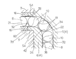
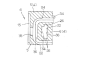
前記セパレータは,前記ローラ列間に位置して隣り合うそれぞれの前記ローラの端面を摺接案内する隔壁,前記隔壁から一方の前記ローラ列へと延びて前記ローラ列の前記ローラの転動面を両側から抱持する一対の第1セパレータ部,及び前記隔壁から他方の前記ローラ列へと延びて前記ローラ列の隣接する前記ローラの転動面間に位置する一つの第2セパレータ部から構成されていることを特徴とする直動案内ユニットに関する。
2 スライダ
3 ケーシング
4 エンドキャップ
8,8A,8B セパレータ
10 ローラ(転動体)
11 軌道面(第1軌道面)
12 軌道面(第2軌道面)
15 凹部
20 軌道路
21 リターン路
22 方向転換路
23 循環路
24 端面
25 側面
26 セパレータ案内溝
27 第1突出部
28 第2突出部
30 隔壁
31 第1セパレータ部
32 第2セパレータ部
33 つば部
34 外周面
36 内周面
38 ローラ端面
39 ローラ転動面
40 外面
41 内面
42 ローラ収容部
43,45 凹曲面
44 凸曲面
46 凹溝
47 凹部又は孔
50 保持板
51 第1保持部
52 第2保持部
53 第3保持部
59 凹溝
62 面取り
Claims (11)
- 長手方向に延びる第1軌道面を備えた軌道レール,前記第1軌道面に対向する第2軌道面を備え且つ前記軌道レールに対して前記第1軌道面と前記第2軌道面との間の軌道路に複数列に組み込まれた転動体であるローラを介して前記軌道レールに対して相対摺動自在なスライダ,前記スライダは,前記第2軌道面と前記第2軌道面に平行に延びるリターン路とが形成されたケーシング,前記ケーシングの両端面に取り付けられて前記軌道路と前記リターン路とを連通する方向転換路が形成されたエンドキャップとを有し,前記ローラと前記ローラ間に組み込まれるセパレータとは,前記軌道路,前記リターン路及び一対の前記方向転換路からなる循環路を転走し,及び1つの前記循環路に複数のローラ列が配設されていることから成る直動案内ユニットにおいて,
前記セパレータは,前記ローラ列間に位置して隣り合うそれぞれの前記ローラの端面を摺接案内する隔壁,前記隔壁から一方の前記ローラ列へと延びて前記ローラ列の前記ローラの転動面を両側から抱持する一対の第1セパレータ部,及び前記隔壁から他方の前記ローラ列へと延びて前記ローラ列の隣接する前記ローラの転動面間に位置する一つの第2セパレータ部から構成されていることを特徴とする直動案内ユニット。 - 複数の前記ローラ列がN列に構成された前記ローラは,隣接する前記ローラ同士の位相がローラピッチの1/Nずれて長手方向に転動することを特徴とする請求項1に記載の直動案内ユニット。
- 前記ローラ列が2列に構成された構造における前記セパレータは,前記ローラ間で前記ローラの移動方向に沿って互い違いに配列されていることを特徴とする請求項1又は2に記載の直動案内ユニット。
- 前記ローラ列が3列に構成された構造における前記セパレータは,前記3列の両側に位置する両側列の前記ローラ間に前記第1セパレータ部が順次介在し,且つ前記ローラ間で前記ローラの移動方向に沿って前記3列の中央に位置する中央列の前記ローラ間に前記第2セパレータ部が順次介在して配列されていることを特徴とする請求項1又は2に記載の直動案内ユニット。
- 一対の前記第1セパレータ部の対向する内面が内曲面に形成されて該内曲面で前記ローラの前記転動面を抱持し,前記第2セパレータ部の両側が内曲面に形成されて該内曲面に前記ローラの前記転動面が接触していることを特徴とする請求項1〜4のいずれか1項に記載の直動案内ユニット。
- 前記循環路の前記方向転換路の内周側に位置する前記セパレータの内面は平面に形成されており,前記循環路の前記方向転換路の外周側に位置する前記セパレータの外面は円弧面に形成されていることを特徴とする請求項1〜5のいずれか1項に記載の直動案内ユニット。
- 前記第1セパレータ部と前記第2セパレータ部は前記ローラと接する柱部から成り,前記柱部の端部は前記ローラの前記転動面を抱持するつば部に形成され,前記つば部は前記軌道路を転動する前記ローラの前記スライダからの脱落を防止していることを特徴とする請求項1〜6のいずれか1項に記載の直動案内ユニット。
- 前記第1セパレータ部の先端面から延びる第1突出部が形成されており,前記第2セパレータ部も先端面から延びる第2突出部が形成されており,前記第1突出部と第2突出部は,前記循環路に形成された案内溝にそれぞれ配設されて前記セパレータを前記循環路で案内することを特徴とする請求項1〜7のいずれか1項に記載の直動案内ユニット。
- 上側の前記軌道路と下側の前記軌道路との間で前記ケーシングに形成された凹部に配置された保持板は,前記第1セパレータ部の前記第1突出部と前記第2セパレータ部の前記第2突出部を前記ケーシングと共働して移動保持するための第1保持部,第2保持部及び第3保持部を有していることを特徴とする請求項8に記載の直動案内ユニット。
- 前記セパレータを前記循環路で案内する前記第1突出部と前記第2突出部は,角部が面取りされた形状又は曲面形状に形成されていることを特徴とする請求項8又は9に記載の直動案内ユニット。
- 前記セパレータには,前記ローラの前記ローラ転動面及び/又は前記ローラ端面に接触する接触面に凹溝,凹部或いは孔から成る油溜まり部が形成されていることを特徴とする請求項1〜10のいずれか1項に記載の直動案内ユニット。
Priority Applications (2)
| Application Number | Priority Date | Filing Date | Title |
|---|---|---|---|
| JP2013252801A JP6329364B2 (ja) | 2013-12-06 | 2013-12-06 | 転動体間にセパレータを配設した直動案内ユニット |
| US14/552,821 US9194428B2 (en) | 2013-12-06 | 2014-11-25 | Linear motion guide unit with separators interposed between adjoining rolling elements |
Applications Claiming Priority (1)
| Application Number | Priority Date | Filing Date | Title |
|---|---|---|---|
| JP2013252801A JP6329364B2 (ja) | 2013-12-06 | 2013-12-06 | 転動体間にセパレータを配設した直動案内ユニット |
Publications (3)
| Publication Number | Publication Date |
|---|---|
| JP2015110961A JP2015110961A (ja) | 2015-06-18 |
| JP2015110961A5 JP2015110961A5 (ja) | 2017-01-05 |
| JP6329364B2 true JP6329364B2 (ja) | 2018-05-23 |
Family
ID=53270702
Family Applications (1)
| Application Number | Title | Priority Date | Filing Date |
|---|---|---|---|
| JP2013252801A Active JP6329364B2 (ja) | 2013-12-06 | 2013-12-06 | 転動体間にセパレータを配設した直動案内ユニット |
Country Status (2)
| Country | Link |
|---|---|
| US (1) | US9194428B2 (ja) |
| JP (1) | JP6329364B2 (ja) |
Families Citing this family (4)
| Publication number | Priority date | Publication date | Assignee | Title |
|---|---|---|---|---|
| US10136938B2 (en) | 2014-10-29 | 2018-11-27 | Ethicon Llc | Electrosurgical instrument with sensor |
| JP6436949B2 (ja) * | 2016-09-02 | 2018-12-12 | 日本ベアリング株式会社 | 直動装置 |
| JP6530010B2 (ja) * | 2017-05-23 | 2019-06-12 | Thk株式会社 | 複列転動体収容バンド及び運動案内装置 |
| USD875150S1 (en) * | 2017-05-31 | 2020-02-11 | Thk Co., Ltd. | End plate for motion guide device |
Family Cites Families (11)
| Publication number | Priority date | Publication date | Assignee | Title |
|---|---|---|---|---|
| JP3219170B2 (ja) | 1993-04-09 | 2001-10-15 | ヒーハイスト精工株式会社 | 直動案内軸受 |
| JP4513994B2 (ja) * | 1998-04-09 | 2010-07-28 | Thk株式会社 | ローラ連結体及びこれを用いた直線案内装置 |
| JP2001132745A (ja) * | 1999-11-05 | 2001-05-18 | Nippon Thompson Co Ltd | 直動転がり案内ユニット |
| US6419069B1 (en) * | 2000-02-11 | 2002-07-16 | Hiroshi Teramachi | Cross roller assembly and cross roller guiding apparatus using the same |
| JP2006002922A (ja) * | 2004-06-21 | 2006-01-05 | Nsk Ltd | 直動案内軸受装置 |
| US7896549B2 (en) * | 2005-10-07 | 2011-03-01 | Hiwin Technologies Corp. | Parallel spacer for a linear guideway |
| JP2007255601A (ja) * | 2006-03-23 | 2007-10-04 | Ntn Corp | 複列ころ軸受およびその組み立て方法 |
| JP2007303608A (ja) * | 2006-05-12 | 2007-11-22 | Nsk Ltd | 保持器付複列ころ軸受 |
| JP2011112069A (ja) * | 2009-11-24 | 2011-06-09 | Thk Co Ltd | 運動案内装置及びローラねじ |
| JP2012026534A (ja) * | 2010-07-26 | 2012-02-09 | Thk Co Ltd | 転動体保持スペーサ及びこれを用いた運動案内装置 |
| WO2013043822A2 (en) * | 2011-09-22 | 2013-03-28 | The Timken Company | Compact planetary gear system with stiffened carrier |
-
2013
- 2013-12-06 JP JP2013252801A patent/JP6329364B2/ja active Active
-
2014
- 2014-11-25 US US14/552,821 patent/US9194428B2/en active Active
Also Published As
| Publication number | Publication date |
|---|---|
| US9194428B2 (en) | 2015-11-24 |
| JP2015110961A (ja) | 2015-06-18 |
| US20150159695A1 (en) | 2015-06-11 |
Similar Documents
| Publication | Publication Date | Title |
|---|---|---|
| JP5820187B2 (ja) | 小形直動案内ユニット | |
| JP4965362B2 (ja) | ローラ形式の直動案内ユニット | |
| JP6329364B2 (ja) | 転動体間にセパレータを配設した直動案内ユニット | |
| JP4505397B2 (ja) | 直動案内ユニット | |
| US7832930B2 (en) | Linear motion guide unit | |
| US8858080B2 (en) | Linear motion guide unit using balls | |
| US8801289B2 (en) | Linear motion guide unit | |
| JP2003194057A (ja) | 転動体間にセパレータを備えた直動案内ユニット | |
| WO2018043045A1 (ja) | 直動装置 | |
| CN110678662B (zh) | 多列滚动体收容带及运动引导装置 | |
| JP2015224713A (ja) | 直動転がり案内ユニット | |
| JP2011149469A (ja) | 直動案内ユニット | |
| JP6393496B2 (ja) | 潤滑部材を備えた直動案内ユニット | |
| JPH05209617A (ja) | 直動転がり案内ユニット | |
| JP4469705B2 (ja) | 直動案内ユニット | |
| JP6710543B2 (ja) | 直動案内ユニット | |
| CN105673687A (zh) | 直线运动引导装置 | |
| JP4340547B2 (ja) | ローラチェーンを組み込んだ案内ユニット | |
| JP5938196B2 (ja) | 直動転がり案内ユニット | |
| US7832929B2 (en) | Linear motion guide unit | |
| JP5668752B2 (ja) | 直動案内装置 | |
| JP2001132745A (ja) | 直動転がり案内ユニット | |
| JP5735374B2 (ja) | 直動転がり案内ユニット | |
| JP2005201361A (ja) | 直動案内装置 | |
| JP2005172027A5 (ja) |
Legal Events
| Date | Code | Title | Description |
|---|---|---|---|
| A521 | Request for written amendment filed |
Free format text: JAPANESE INTERMEDIATE CODE: A523 Effective date: 20161116 |
|
| A621 | Written request for application examination |
Free format text: JAPANESE INTERMEDIATE CODE: A621 Effective date: 20161116 |
|
| A977 | Report on retrieval |
Free format text: JAPANESE INTERMEDIATE CODE: A971007 Effective date: 20170818 |
|
| A131 | Notification of reasons for refusal |
Free format text: JAPANESE INTERMEDIATE CODE: A131 Effective date: 20170912 |
|
| A521 | Request for written amendment filed |
Free format text: JAPANESE INTERMEDIATE CODE: A523 Effective date: 20170929 |
|
| A131 | Notification of reasons for refusal |
Free format text: JAPANESE INTERMEDIATE CODE: A131 Effective date: 20180306 |
|
| A521 | Request for written amendment filed |
Free format text: JAPANESE INTERMEDIATE CODE: A523 Effective date: 20180312 |
|
| TRDD | Decision of grant or rejection written | ||
| A01 | Written decision to grant a patent or to grant a registration (utility model) |
Free format text: JAPANESE INTERMEDIATE CODE: A01 Effective date: 20180417 |
|
| A61 | First payment of annual fees (during grant procedure) |
Free format text: JAPANESE INTERMEDIATE CODE: A61 Effective date: 20180420 |
|
| R150 | Certificate of patent or registration of utility model |
Ref document number: 6329364 Country of ref document: JP Free format text: JAPANESE INTERMEDIATE CODE: R150 |
|
| R250 | Receipt of annual fees |
Free format text: JAPANESE INTERMEDIATE CODE: R250 |
|
| R250 | Receipt of annual fees |
Free format text: JAPANESE INTERMEDIATE CODE: R250 |