JP6329364B2 - Linear motion guide unit with separators between rolling elements - Google Patents
Linear motion guide unit with separators between rolling elements Download PDFInfo
- Publication number
- JP6329364B2 JP6329364B2 JP2013252801A JP2013252801A JP6329364B2 JP 6329364 B2 JP6329364 B2 JP 6329364B2 JP 2013252801 A JP2013252801 A JP 2013252801A JP 2013252801 A JP2013252801 A JP 2013252801A JP 6329364 B2 JP6329364 B2 JP 6329364B2
- Authority
- JP
- Japan
- Prior art keywords
- separator
- roller
- rollers
- linear motion
- rows
- Prior art date
- Legal status (The legal status is an assumption and is not a legal conclusion. Google has not performed a legal analysis and makes no representation as to the accuracy of the status listed.)
- Active
Links
- 238000005096 rolling process Methods 0.000 title claims description 40
- 238000005192 partition Methods 0.000 claims description 16
- 230000002093 peripheral effect Effects 0.000 claims description 12
- 230000010363 phase shift Effects 0.000 claims 1
- 238000004519 manufacturing process Methods 0.000 description 5
- 238000003780 insertion Methods 0.000 description 3
- 230000037431 insertion Effects 0.000 description 3
- 230000001050 lubricating effect Effects 0.000 description 3
- 125000006850 spacer group Chemical group 0.000 description 3
- 239000010419 fine particle Substances 0.000 description 2
- 239000004519 grease Substances 0.000 description 2
- 239000000314 lubricant Substances 0.000 description 2
- 210000002445 nipple Anatomy 0.000 description 2
- 229920005989 resin Polymers 0.000 description 2
- 239000011347 resin Substances 0.000 description 2
- 239000004065 semiconductor Substances 0.000 description 2
- 238000003491 array Methods 0.000 description 1
- 238000009795 derivation Methods 0.000 description 1
- 230000002452 interceptive effect Effects 0.000 description 1
- 230000013011 mating Effects 0.000 description 1
- 239000011148 porous material Substances 0.000 description 1
- 238000007789 sealing Methods 0.000 description 1
- 229920003002 synthetic resin Polymers 0.000 description 1
- 239000000057 synthetic resin Substances 0.000 description 1
- 238000003856 thermoforming Methods 0.000 description 1
Images


Classifications
-
- F—MECHANICAL ENGINEERING; LIGHTING; HEATING; WEAPONS; BLASTING
- F16—ENGINEERING ELEMENTS AND UNITS; GENERAL MEASURES FOR PRODUCING AND MAINTAINING EFFECTIVE FUNCTIONING OF MACHINES OR INSTALLATIONS; THERMAL INSULATION IN GENERAL
- F16C—SHAFTS; FLEXIBLE SHAFTS; ELEMENTS OR CRANKSHAFT MECHANISMS; ROTARY BODIES OTHER THAN GEARING ELEMENTS; BEARINGS
- F16C33/00—Parts of bearings; Special methods for making bearings or parts thereof
- F16C33/30—Parts of ball or roller bearings
- F16C33/37—Loose spacing bodies
- F16C33/3706—Loose spacing bodies with concave surfaces conforming to the shape of the rolling elements, e.g. the spacing bodies are in sliding contact with the rolling elements
-
- F—MECHANICAL ENGINEERING; LIGHTING; HEATING; WEAPONS; BLASTING
- F16—ENGINEERING ELEMENTS AND UNITS; GENERAL MEASURES FOR PRODUCING AND MAINTAINING EFFECTIVE FUNCTIONING OF MACHINES OR INSTALLATIONS; THERMAL INSULATION IN GENERAL
- F16C—SHAFTS; FLEXIBLE SHAFTS; ELEMENTS OR CRANKSHAFT MECHANISMS; ROTARY BODIES OTHER THAN GEARING ELEMENTS; BEARINGS
- F16C29/00—Bearings for parts moving only linearly
- F16C29/04—Ball or roller bearings
- F16C29/06—Ball or roller bearings in which the rolling bodies circulate partly without carrying load
- F16C29/0633—Ball or roller bearings in which the rolling bodies circulate partly without carrying load with a bearing body defining a U-shaped carriage, i.e. surrounding a guide rail or track on three sides
- F16C29/0635—Ball or roller bearings in which the rolling bodies circulate partly without carrying load with a bearing body defining a U-shaped carriage, i.e. surrounding a guide rail or track on three sides whereby the return paths are provided as bores in a main body of the U-shaped carriage, e.g. the main body of the U-shaped carriage is a single part with end caps provided at each end
- F16C29/065—Ball or roller bearings in which the rolling bodies circulate partly without carrying load with a bearing body defining a U-shaped carriage, i.e. surrounding a guide rail or track on three sides whereby the return paths are provided as bores in a main body of the U-shaped carriage, e.g. the main body of the U-shaped carriage is a single part with end caps provided at each end with rollers
-
- F—MECHANICAL ENGINEERING; LIGHTING; HEATING; WEAPONS; BLASTING
- F16—ENGINEERING ELEMENTS AND UNITS; GENERAL MEASURES FOR PRODUCING AND MAINTAINING EFFECTIVE FUNCTIONING OF MACHINES OR INSTALLATIONS; THERMAL INSULATION IN GENERAL
- F16C—SHAFTS; FLEXIBLE SHAFTS; ELEMENTS OR CRANKSHAFT MECHANISMS; ROTARY BODIES OTHER THAN GEARING ELEMENTS; BEARINGS
- F16C29/00—Bearings for parts moving only linearly
- F16C29/04—Ball or roller bearings
- F16C29/06—Ball or roller bearings in which the rolling bodies circulate partly without carrying load
- F16C29/0633—Ball or roller bearings in which the rolling bodies circulate partly without carrying load with a bearing body defining a U-shaped carriage, i.e. surrounding a guide rail or track on three sides
- F16C29/0652—Ball or roller bearings in which the rolling bodies circulate partly without carrying load with a bearing body defining a U-shaped carriage, i.e. surrounding a guide rail or track on three sides whereby the return paths are at least partly defined by separate parts, e.g. covers attached to the legs of the main body of the U-shaped carriage
- F16C29/0666—Ball or roller bearings in which the rolling bodies circulate partly without carrying load with a bearing body defining a U-shaped carriage, i.e. surrounding a guide rail or track on three sides whereby the return paths are at least partly defined by separate parts, e.g. covers attached to the legs of the main body of the U-shaped carriage with rollers
Landscapes
- Engineering & Computer Science (AREA)
- General Engineering & Computer Science (AREA)
- Mechanical Engineering (AREA)
- Bearings For Parts Moving Linearly (AREA)
- Rolling Contact Bearings (AREA)
Description
この発明は,例えば,各種の組立装置,工作機械,産業用ロボット,半導体製造装置等の摺動部分に使用される転動体間にセパレータを配設した直動案内ユニットに関する。 The present invention relates to a linear motion guide unit in which a separator is disposed between rolling elements used in sliding parts of various assembly devices, machine tools, industrial robots, semiconductor manufacturing devices, and the like.
従来,1つの軌道路にローラを複数条列配置したローラタイプの直動案内ユニットである直動案内軸受が知られている。該直動案内軸受は,同一軌道内にローラ部材を複数条列配設してスキュー,微小振動の発生を抑制しようとするものであって,軸受本体の軸受凹部に2条列のローラコロを無限循環させる軌道を形成し,軸と軸受本体とを互いに直動運動可能に構成したものである。2条列のローラコロは,軌道において条列毎に互いにローラコロの半径分ずらして配置し,互いに独立して自在に移動可能に構成されている(例えば,特許文献1参照)。 2. Description of the Related Art Conventionally, a linear motion guide bearing is known which is a roller type linear motion guide unit in which a plurality of rollers are arranged in a single track. The linear motion guide bearing is intended to suppress the occurrence of skew and minute vibration by arranging a plurality of roller members in the same track, and infinite two rows of roller rollers in the bearing recess of the bearing body. A circulating raceway is formed, and the shaft and the bearing body are configured to be capable of linear motion relative to each other. The two rows of roller rollers are arranged so as to be shifted from each other by the radius of the roller rollers for each row in the track, and are configured to be freely movable independently of each other (see, for example, Patent Document 1).
また,取付け面の傾き誤差や偏荷重があってもスキューが発生しないように構成した運動案内装置及びローラねじが知られている。該運動案内装置は,ローラタイプの直動案内ユニットであって,複数条のローラ循環路に配列されたローラが樹脂製リテーナに保持され,一循環路あたり二列のローラが配設されている。上記運動案内装置は,軌道部材と複数条のローラ転動面に対向する複数条の負荷ローラ転動面と複数条の無負荷戻し路を接続する複数の方向転換路を有する移動部材と,複数条のローラ循環路に配列される複数のローラとを備えている。複数条のローラ循環路の少なくとも一条のローラ循環路には,一条あたり二列以上の複数のローラが配列され,軌道部材に対してその長手方向に相対的に移動部材を移動させると,二列以上の複数のローラが軌道部材のローラ転動面と移動部材の負荷ローラ転動面との間を転がり運動し,ローラ循環路を循環する(例えば,特許文献2参照)。 There are also known a motion guide device and a roller screw configured so that no skew occurs even if there is an inclination error or an offset load on the mounting surface. The motion guide device is a roller type linear motion guide unit, in which rollers arranged in a plurality of roller circulation paths are held by a resin retainer, and two rows of rollers are arranged per circulation path. . The movement guide device includes a moving member having a plurality of direction change paths connecting a plurality of load roller rolling surfaces facing a raceway member and a plurality of roller rolling surfaces and a plurality of unloaded return paths, And a plurality of rollers arranged in the roller circulation path. In at least one roller circulation path of the plurality of roller circulation paths, a plurality of rollers are arranged in two or more per line, and when the moving member is moved relative to the track member in the longitudinal direction, two rows are arranged. The plurality of rollers described above roll and move between the roller rolling surface of the track member and the load roller rolling surface of the moving member, and circulate through the roller circulation path (see, for example, Patent Document 2).
ところで,上記直動案内軸受では,隣り合うローラの端面同士が接触しながら自転することによって,ローラの摺動が抵抗となり重くなるという問題がある。また,上記運動案内装置は,二列以上のローラを保持するリテーナが複雑で,大掛かりな構造になり,製造し難いという問題を有している。 By the way, the linear motion guide bearing has a problem that the sliding of the roller becomes a resistance and becomes heavy because the end surfaces of the adjacent rollers rotate while being in contact with each other. Further, the motion guide device has a problem that the retainer for holding two or more rows of rollers is complicated, has a large structure, and is difficult to manufacture.
この発明の目的は,上記の課題を解決することであり,1つの循環路あたりに2列以上のN列のローラ列を配列し,前記ローラ列をそれぞれ転走するローラ同士の位相が前記ローラ列における前記ローラのピッチの1/Nずれた千鳥状に配置されるように,前記ローラ列間と前記ローラ列のそれぞれの前記ローラ間にそれぞれ跨がってセパレータを組み込んだ構造であって,そのため前記セパレータを前記ローラ列間に位置する隔壁と前記隔壁の両側からそれぞれ延び且つ前記ローラ列のそれぞれの前記ローラ間に配設された第1セパレータ部と第2セパレータ部から構成し,前記セパレータが前記ローラ同士の位相を確実に常にずらして案内し,前記ローラの方向転換路から軌道路への負荷域への出入り時に発生するスライダの姿勢変化を小さくし,前記スライダの走行精度を向上させることを特徴とする転動体間にセパレータを配設した直動案内ユニットを提供することである。 SUMMARY OF THE INVENTION An object of the present invention is to solve the above-described problem, wherein two or more N rows of rollers are arranged per circuit, and the phases of the rollers that respectively roll on the roller rows are the rollers. A structure in which separators are incorporated between the roller rows and between the rollers of the roller rows so as to be arranged in a staggered manner with a shift of 1 / N of the pitch of the rollers in the rows, Therefore, the separator is composed of a partition located between the roller rows and first and second separator portions extending from both sides of the partition and disposed between the rollers of the roller row. Guides the phases of the rollers to be surely shifted, and the change in the posture of the slider that occurs when the rollers enter and exit the load path from the direction change path to the track path. Illusion, is to provide a linear motion guide unit which is disposed a separator between the rolling elements, characterized in that to improve the running accuracy of the slider.
この発明は,長手方向に延びる第1軌道面を備えた軌道レール,前記第1軌道面に対向する第2軌道面を備え且つ前記軌道レールに対して前記第1軌道面と前記第2軌道面との間の軌道路に複数列に組み込まれた転動体であるローラを介して前記軌道レールに対して相対摺動自在なスライダ,前記スライダは,前記第2軌道面と前記第2軌道面に平行に延びるリターン路とが形成されたケーシング,前記ケーシングの両端面に取り付けられて前記軌道路と前記リターン路とを連通する方向転換路が形成されたエンドキャップとを有し,前記ローラと前記ローラ間に組み込まれるセパレータとは,前記軌道路,前記リターン路及び一対の前記方向転換路からなる循環路を転走し,及び1つの前記循環路に複数のローラ列が配設されていることから成る直動案内ユニットにおいて,
前記セパレータは,前記ローラ列間に位置して隣り合うそれぞれの前記ローラの端面を摺接案内する隔壁,前記隔壁から一方の前記ローラ列へと延びて前記ローラ列の前記ローラの転動面を両側から抱持する一対の第1セパレータ部,及び前記隔壁から他方の前記ローラ列へと延びて前記ローラ列の隣接する前記ローラの転動面間に位置する一つの第2セパレータ部から構成されていることを特徴とする直動案内ユニットに関する。
The present invention includes a track rail having a first track surface extending in a longitudinal direction, a second track surface facing the first track surface, and the first track surface and the second track surface with respect to the track rail. The slider is slidable relative to the track rail via rollers that are rolling elements incorporated in a plurality of rows in the track between the slider and the slider on the second track surface and the second track surface. A casing formed with a return path extending in parallel; an end cap attached to both end faces of the casing and formed with a direction changing path that connects the track path and the return path; and the roller and the The separator incorporated between the rollers is a rolling path composed of the track path, the return path, and the pair of direction changing paths, and a plurality of roller rows are arranged in one of the circulating paths. Or In the linear motion guide unit comprising,
The separator is positioned between the roller rows and slidably guides the end surfaces of the adjacent rollers. The separator extends from the partition to one of the roller rows so that the rolling surface of the roller of the roller row is provided. A pair of first separator portions held from both sides, and one second separator portion extending from the partition wall to the other roller row and positioned between the rolling surfaces of the rollers adjacent to the roller row. The present invention relates to a linear motion guide unit.
また,複数の前記ローラ列がN列に構成された前記ローラは,隣接する前記ローラ同士の位相がローラピッチの1/Nずれて長手方向に転動するものである。 Further, the rollers in which the plurality of roller rows are configured as N rows roll in the longitudinal direction with the phases of the adjacent rollers shifted by 1 / N of the roller pitch.
また,この直動案内ユニットにおいて,前記ローラ列が2列に構成された構造における前記セパレータは,前記ローラ間で前記ローラの移動方向に沿って互い違いに配列されている。或いは,前記ローラ列が3列に構成された構造における前記セパレータは,前記3列の両側に位置する両側列の前記ローラ間に前記第1セパレータ部が順次介在し,且つ前記ローラ間で前記ローラの移動方向に沿って前記3列の中央に位置する中央列の前記ローラ間に前記第2セパレータ部が順次介在して配列されている。 Further, in this linear motion guide unit, the separators in the structure in which the roller rows are configured in two rows are alternately arranged between the rollers along the moving direction of the rollers. Alternatively, in the separator having a structure in which the roller rows are arranged in three rows, the first separator portion is sequentially interposed between the rollers in both side rows located on both sides of the three rows, and the rollers are arranged between the rollers. The second separator portions are sequentially arranged between the rollers in the central row located at the center of the three rows along the moving direction of the second row.
また,この直動案内ユニットにおいて,一対の前記第1セパレータ部の対向する内面が内曲面に形成されて該内曲面で前記ローラのローラ転動面を抱持し,前記第2セパレータ部の両側が内曲面に形成されて該内曲面に前記ローラのローラ転動面が接触している。また,前記循環路の前記方向転換路の内周側に位置する前記セパレータの内面は平面に形成されており,前記循環路の前記方向転換路の外周側に位置する前記セパレータの外面は円弧面に形成されている。 Further, in this linear motion guide unit, opposing inner surfaces of the pair of first separator portions are formed in an inner curved surface, and the inner curved surface holds the roller rolling surface of the roller, and both sides of the second separator portion. Is formed on an inner curved surface, and the roller rolling surface of the roller is in contact with the inner curved surface. The inner surface of the separator located on the inner peripheral side of the direction change path of the circulation path is formed in a plane, and the outer surface of the separator located on the outer periphery side of the direction change path of the circulation path is an arc surface. Is formed.
また,この直動案内ユニットにおいて,前記第1セパレータ部と前記第2セパレータ部は前記ローラと接する柱部から成り,前記柱部の端部は前記ローラの前記転動面を抱持するつば部に形成され,前記つば部は前記軌道路を転動する前記ローラの前記スライダからの脱落を防止している。 Further, in this linear motion guide unit, the first separator portion and the second separator portion are formed of a column portion in contact with the roller, and an end portion of the column portion is a collar portion that holds the rolling surface of the roller. The collar portion prevents the roller rolling on the track from falling off the slider.
また,この直動案内ユニットは,前記第1セパレータ部の先端面から延びる第1突出部が形成されており,前記第2セパレータ部も先端面から延びる第2突出部が形成されており,前記第1突出部と第2突出部は,前記循環路に形成された案内溝にそれぞれ案内されて前記セパレータを前記循環路で案内するものである。更に,上側の前記軌道路と下側の前記軌道路との間で前記ケーシングに形成された凹部に配置された保持板は,前記第1セパレータ部の前記第1突出部と前記第2セパレータ部の前記第2突出部を前記ケーシングと共働して移動保持するための第1保持部,第2保持部,及び第3保持部を有しているものである。更に,前記セパレータを前記循環路で案内する前記第1突出部と前記第2突出部は,角部が面取りされた形状又は曲面形状に形成されているものである。 The linear motion guide unit is formed with a first protrusion extending from the front end surface of the first separator portion, and the second separator portion is also formed with a second protrusion extending from the front end surface. The first projecting portion and the second projecting portion are respectively guided by guide grooves formed in the circulation path to guide the separator in the circulation path. Furthermore, the holding plate disposed in the recess formed in the casing between the upper raceway and the lower raceway includes the first projecting portion and the second separator portion of the first separator portion. The second protrusion has a first holding part, a second holding part, and a third holding part for moving and holding in cooperation with the casing. Furthermore, the first protrusion and the second protrusion that guide the separator along the circulation path are formed in a shape with a chamfered corner or a curved surface.
また,この直動案内ユニットは,前記セパレータには,前記ローラの前記ローラ転動面及び/又は前記ローラ端面に接触する接触面に凹溝,凹部或いは孔から成る油溜まり部が形成されている。 Further, in this linear motion guide unit, the separator is formed with an oil reservoir comprising a concave groove, a concave portion or a hole on a contact surface that contacts the roller rolling surface and / or the roller end surface of the roller. .
この発明による直動案内ユニットは,上記のように,1つの循環路に複数のローラ列が配設されているので,負荷を受けるローラ本数が増加し,ローラ本数全体に占める変動率を小さくでき,スライダの姿勢変化を小さくしてスライダの往復移動における走行振れを抑制し,スライダの走行精度を向上させることができ,特に,セパレータが複数のローラ列に跨がって且つ各ローラ列におけるローラ間に組み込まれるので,隣接するローラ列同士の位相をずらして転走させることができ,各ローラ列におけるローラが同時に負荷域の軌道路に出入りすることがないので,負荷域にあるローラ本数の変動率を小さく抑え,スライダの姿勢変化を小さく抑え,スライダの走行振れを抑制してスライダの走行性能を向上させることができる。しかるに,従来の直動案内ユニットは,転動体のローラが循環路即ち無限循環路を循環して軌道路の負荷域を出入りするが,ローラと軌道面には弾性変形が生じると共に,軌道路に存在するローラ本数が周期的に変化し,スライダが軌道レールに対して上下方向に姿勢変動し,また,スライダがモーメント荷重の負荷により,ピッチング,ヨーイング,ローリングの3方向への姿勢変化が生じるが,この発明による直動案内ユニットは,上記の問題点を解決することができる。また,セパレータは,構造がシンプルであり,製造が簡単であり,製造コストを低減できる。また,この直動案内ユニットは,セパレータとローラの数を調整すれば,1種類のセパレータで種々のスライダ長さにも対応できる。更に,この直動案内ユニットは,従来のローラを千鳥状に配設したものに比較して,セパレータが方向転換路内を含めて循環路内に形成された案内溝に案内され,ローラとセパレータとがスムーズに走行でき,結果的にスライダが軌道レール上を円滑に往復移動することができる。 As described above, the linear motion guide unit according to the present invention has a plurality of roller rows arranged in one circulation path, so that the number of rollers receiving a load increases and the rate of change in the total number of rollers can be reduced. , It is possible to reduce the movement of the slider in the reciprocating movement of the slider by reducing the change in the attitude of the slider and improve the slider traveling accuracy. In particular, the separator extends over a plurality of roller rows and the rollers in each roller row Since it is incorporated in between, it is possible to roll the rollers while shifting the phase between adjacent roller arrays, and the rollers in each roller array do not enter or exit the track in the load area at the same time. It is possible to improve the running performance of the slider by reducing the fluctuation rate, minimizing the change in the attitude of the slider, and suppressing the runout of the slider. However, in the conventional linear motion guide unit, the roller of the rolling element circulates in the circulation path, that is, the infinite circulation path, and enters and exits the load area of the raceway. Although the number of existing rollers changes periodically, the attitude of the slider fluctuates in the vertical direction with respect to the track rail, and the attitude of the slider changes in three directions: pitching, yawing and rolling. The linear motion guide unit according to the present invention can solve the above problems. In addition, the separator has a simple structure, is easy to manufacture, and can reduce manufacturing costs. In addition, this linear motion guide unit can accommodate various slider lengths with one type of separator by adjusting the number of separators and rollers. Furthermore, in this linear motion guide unit, the separator is guided in the guide groove formed in the circulation path including the direction change path, compared with the conventional rollers arranged in a staggered manner. As a result, the slider can reciprocate smoothly on the track rail.
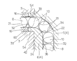
以下,図面を参照して,この発明による転動体間にセパレータを配設した直動案内ユニットの一実施例について説明する。この発明による直動案内ユニットは,概して,図1〜図3に示すように,ベッド等のベースに取り付けるための上面から下面へ貫通する取付け用孔18,長手方向の両側面25に沿って一対の軌道面11(第1軌道面)がそれぞれ形成された軌道レール1,軌道面11に対向して形成された軌道面12(第2軌道面)を備えて軌道レール1に跨架して複数の転動体であるローラ10を介して長手方向に相対移動自在なスライダ2,各列のローラ10が互いに干渉しないように転走させるためローラ10間に介在されたセパレータ8を有している。この直動案内ユニットでは,ローラ10が循環路23をスムーズに転走ができるように,ローラ10間には後述のセパレータ8が介在されている。この直動案内ユニットは,軌道レール1に形成された軌道面11とスライダ2に形成された軌道面12とは,左右に二条列ずつそれぞれ形成され,それぞれの軌道面11と軌道面12とで合計で4つの軌道路20がそれぞれ形成されている。この直動案内ユニットは,例えば,軌道レール1の幅寸法が約55mm程度の大型タイプに適用して好ましいものである。また,スライダ2は,フランジタイプであり,主として,軌道面11と軌道面12との間に形成される一対の軌道路20に沿って延びる一対のリターン路21が形成されると共に各種の機器,ワーク等の相手部材(図示せず)を取り付けるための取付け用ねじ孔19が形成されたケーシング3,ケーシング3の両端面24にそれぞれ取り付けられ且つ軌道路20とリターン路21とを連通する円弧形状に延びる方向転換路22が形成されたエンドキャップ4,エンドキャップ4の外端面55に取り付けられ且つ軌道レール1の対向面に位置するリップ部14及びリップ部14以外の全面に芯金9を備えたエンドシール13,軌道路20,リターン路21及び一対の方向転換路22で構成される循環路23を転走するローラ10とセパレータ8,及びローラ10を潤滑するためエンドキャップ4に形成された凹部15に配設された潤滑剤が含浸された潤滑部材7を有している。ローラ10は,略円柱形であり,循環路23を転走するローラ転動面39とその両端のローラ端面38から形成されている。ケーシング3には,エンドキャップ4及びエンドシール13が固定ボルト49によって固定されている。
Hereinafter, an embodiment of a linear motion guide unit in which a separator is disposed between rolling elements according to the present invention will be described with reference to the drawings. 1 to 3, the linear motion guide unit according to the present invention generally has a pair of mounting
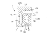
また,この直動案内ユニットにおいて,ケーシング3に形成されたリターン路21は,ケーシング3に長手方向に形成された嵌挿孔60に嵌挿されたスリーブ16の通し孔で形成されている。スリーブ16は,エンドキャップ4の端面に設けた接続部54を嵌合して取り付けられ,方向転換路22がリターン路21に無段でスムーズに連結されている。また,エンドキャップ4は,反ケーシング3側に方向転換路22の外周面34が形成され且つケーシング3側に開口した凹部56が形成されたエンドキャップ本体5,及び反ケーシング側に方向転換路22の内周面36が形成され且つエンドキャップ本体5に形成された凹部56に嵌合配置されたスペーサ6から構成されている。また,エンドキャップ4は,エンドキャップ本体5に形成された凹部56にスペーサ6が嵌合して組み立てられ,それによって,方向転換路22は,エンドキャップ本体5に形成された方向転換路22の外周面34とスペーサ6に形成された方向転換路22の内周面36とが対向して整合することによって形成されている。また,エンドキャップ本体5の反ケーシング3側の外端面55には,潤滑部材7を収容する凹部15が形成されている。潤滑部材7は,例えば,超高分子量の合成樹脂微粒子を押し固めた状態で加熱成形して微粒子間のポアが連通して多孔質成形体の焼結樹脂で形成することができ,その形状は,エンドキャップ本体5の上部に相当する領域の凹部15に配設される貯留部7A,及び貯留部7Aに一体的に形成され且つエンドキャップ本体5の方向転換路22に開口する開口部35に嵌入する導出部7Bから構成されている。導出部7Bの先端面57は,方向転換路22の開口部35に露出するように構成されている。また,スライダ2は,軌道レール1の側面25とスライダ2の下面との間のすきまを密封するための下面シール29を備えている。スライダ2に潤滑剤を給油するためのグリースニップル48を取り付けるためのグリースニップル取付け用ねじ孔がエンドキャップ4に設けられている。また,ローラ10は,循環路23における軌道路20では負荷を受けて転動し,リターン路21及び方向転換路22では無負荷で転走し,また,セパレータ8が循環路23ではローラ10間に介在してローラ10と共に転走する。ローラ10及びセパレータ8は,軌道路20では保持板50によって保持されており,保持板50は,ケーシング3に形成された凹部17に配設されて,ケーシング3に形成されている挿通孔61に通した固定ボルト37によってケーシング3に固定されている。
Further, in this linear motion guide unit, the
この発明による直動案内ユニットは,特に,1つの循環路23で2列以上のN列のローラ列を配列したものであり,ローラ列間とローラ10間に配設されるセパレータ8に特徴を有している。この実施例の図2〜図4に示すように,ローラ10は,1つの循環路23で2列に配設されている。各ローラ列を転走するローラ10のそれぞれの位相は,N列の場合には,ローラ10のピッチの1/Nずれて千鳥状に配置に構成されており,この実施例では,1つの循環路23に2列のローラ10が配設されているので,隣接するローラ10同士の位相がローラピッチの1/2ずれて長手方向に転動するものである。この直動案内ユニットは,各ローラ10間にセパレータ8を配設して1個のセパレータ8が隣接するローラ列に跨がって組み込まれており,セパレータ8は,ローラ列間におけるローラ10同士の位相を確実に常にずらして案内し,ローラ10の方向転換路22から軌道路20への負荷域への出入りで発生するスライダ2の姿勢変化を小さくし,直動案内ユニットの走行精度を向上させている。また,保持板50は,ローラ10及びセパレータ8を配設するため両側部長手方向に沿って長孔形状の一対の開口部58を有し,上下側の軌道面12の開口部58の内側である長手方向に沿ってそれぞれ延びるつば部を構成する第1保持部51,上側の軌道面12の開口部58の外側に位置する長手方向に沿って延びるつば部を構成する第2保持部52,及び下側の軌道面12の開口部58の外側に位置する長手方向に沿って延びるつば部33を構成する第3保持部53から一体構造に構成されている。第1保持部51,第2保持部52,及び第3保持部53は,それぞれ別体に形成してケーシング3又はエンドキャップ4にそれぞれ取り付けることも可能である。
The linear motion guide unit according to the present invention is particularly characterized in that two or more N rows of rollers are arranged in one
図9〜図16に示すように,セパレータ8は,ローラ10の列間の隣合うそれぞれのローラ10のローラ端面38をそれぞれ摺接案内する案内壁を構成する仕切板である隔壁30,隔壁30から列の一方側に延びて一方の列のローラ10のローラ転動面39を両側から抱持する一対の柱部で構成された第1セパレータ部31,及び隔壁30から列の一方側に対する他方側で第1セパレータ部31の間に位置即ちP/2ずれて延びて隣接する列の他方のローラ10のローラ転動面39間に挟まれた一つの柱部で構成された第2セパレータ部32から構成されていることを特徴としている。セパレータ8は,図17に模式的に示すように,それぞれのローラ10が互いに干渉せずに転走できるように,隣接するローラ10のローラ列に跨がって配設されている。言い換えれば,セパレータ8は,その中央に隔壁30を位置させて隣接するローラ10をそれぞれ独立させてローラ端面38を摺接案内し,隔壁30の一側に一対の第1セパレータ部31を突出させ,隔壁30の他側に第2セパレータ部32を突出させて,隔壁30,一対の第1セパレータ部31及び第2セパレータ部32を一体構造に形成している。一対の第1セパレータ部31を構成する柱部には,対向する凹曲面43と反対側の凸曲面44が形成され,第2セパレータ部32を構成する柱部には,両面が凹曲面45に形成されており,凹曲面43と凹曲面45とはローラ転動面39が接触する接触面を構成している。また,複数列が2列に構成された構造におけるセパレータ8は,図9に示すように,ローラ10間で長手方向に沿って互い違いに配列,即ち,一方の列のローラ列では,第1セパレータ部31と第2セパレータ部32が交互に位置するように配設され,それに伴って,他方の列のローラ列では第2セパレータ部32と第1セパレータ部31が交互に位置するように配設されることになる。また,一対の第1セパレータ部31は,互いに対向する一面が凹曲面43から成るローラ収容部42を形成され,他面が凸曲面44に形成されており,1個のローラ10を凹曲面43で挟んだ状態でローラ転動面39を保持し,即ち,1個のローラ10を抱持するように構成されている。また,第2セパレータ部32は,移動方向に隣接するローラ10のローラ転動面39に接触するよう両面が凹曲面45に形成されて,2個のローラ10の間に挟まれた状態に延びている。
As shown in FIGS. 9 to 16, the
また,この直動案内ユニットでは,ローラ10とローラ10間のセパレータ8とは,軌道路20,リターン路21及び一対の方向転換路22から成る循環路23を転走するが,セパレータ8については,循環路23の外周側,即ち,方向転換路22の外周面34,リターン路21の外側,及び軌道レール1の軌道面11に位置する側の外面40(図9では上面)は,曲面形状即ち円弧面に形成されており,外面40の円弧面の断面形状の半径寸法は,セパレータ8と方向転換路22の干渉を防止するため,方向転換路22の外周面34の半径寸法よりも小さく形成されている。また,循環路23の内周側,即ち,方向転換路22の内周面36,リターン路21の内側,及びケーシング3の軌道面12に位置する側の内面41(図9では下面)は,平面に形成されている。また,この直動案内ユニットにおいて,第1セパレータ部31と第2セパレータ部32との端部には,ローラ10のローラ転動面39を抱持するつば部33に形成されており,つば部33は,軌道路20を転動するローラ10のスライダ2からの脱落を防止する機能を果たしている。
In this linear motion guide unit, the
また,この直動案内ユニットは,セパレータ8には,第1セパレータ部31の先端側の端面から延びる第1突出部27,及び第2セパレータ部32の先端側の端面から延びる第2突出部28が形成されている。エンドキャップ4は,図8に示すように,方向転換路22の内周側にセパレータ案内溝26が形成されている。第1突出部27と第2突出部28は,セパレータ8を循環路23で案内するため循環路23,特に,エンドキャップ4の方向転換路22に形成されたセパレータ8を案内する案内溝であるセパレータ案内溝26及び軌道路20における保持板50とケーシング3の軌道面12とで形成される凹溝59(図4参照)で案内されるように構成されている。また,この直動案内ユニットにおいて,図2の上側の軌道路20と下側の軌道路20との間で,ケーシング3に形成された凹部17に配置された保持板50は,セパレータ8の第1突出部27と第2突出部28を保持して移動させる案内溝である凹溝59をケーシング3と共働して形成している。具体的には,図4に示すように,第1突出部27は第1保持部51とケーシング3の軌道面12との間に形成される凹溝59にガイドされ,第2突出部28は,第2保持部52とケーシング3の軌道面12との間に形成される凹溝59にガイドされ,更に,第3保持部53とケーシング3の軌道面12との間に形成される凹溝59にガイドされるように構成されている。また,セパレータ8を循環路23で案内する第1突出部27及び第2突出部28には,角部が面取り62をされた形状又は曲面形状に形成されている。
In the linear motion guide unit, the
また,図3〜図7を参照して,循環路23におけるローラ10とセパレータ8との往復移動状態を説明する。図3には,ローラ10とセパレータ8との循環路23での往復移動に位置関係が全体的に示されている。図4には,この直動案内ユニットの上側の軌道路20におけるローラ10とセパレータ8との保持板50による保持状態が拡大して示されている。保持板50の形成された開口部58の縁部に形成されたつば部である第1保持部51及び第2保持部52と,ケーシング3の軌道面12との間には,両者がそれぞれ共働して軌道路20の上下に凹溝59が形成されており,凹溝59には,セパレータ8に形成された第1突出部27と第2突出部28とが嵌挿し,凹溝59によってセパレータ8とローラ10とがガイドされて軌道路20を往復移動するように構成されている。図5には,直動案内ユニットの軌道路20におけるセパレータ8とローラ10との往復移動の位置関係が示されている。ローラ10は,セパレータ8で隔置されて等ピッチPで軌道路20でそれぞれ転動し,セパレータ8は,交互に向きが反対方向になって1.5Pの間隔に位置している(図17)。図6には,方向転換路22とリターン路21との連通箇所におけるセパレータ8とローラ10との位置関係が示されている。図7には,セパレータ8とローラ10は,図6に示す位置からリターン路21と方向転換路22との連通位置で約45°移動した状態が示されている。セパレータ8は,第1セパレータ部31の外面を円弧状の凸曲面44に形成することで,循環路23の方向転換路22内でローラ10のローラ転動面39となめらかに接触して,ローラ10をスムーズに案内する(図7参照)。
Further, with reference to FIGS. 3 to 7, that describes a reciprocating movement state between the
次に,図18及び図19を参照して,この発明による直動案内ユニットの別の実施例を説明する。この直動案内ユニットにおいて,セパレータ8Aには,ローラ10のローラ転動面39及び/又はローラ端面38に接触する接触面等の表面に凹溝46,凹部或いは孔47から成る油溜まり部が形成されている。凹溝46,凹部或いは孔47は,予め決められた所定の場所,例えば,ローラ10が直接接触する面が好ましい。セパレータ8Aは,凹溝46,凹部或いは孔47が形成されている以外はセパレータ8と同一の構成を有しているので,それらについては同一符号を付して説明を省略する。
Next, another embodiment of the linear motion guide unit according to the present invention will be described with reference to FIGS. In this linear motion guide unit, the
また,図20〜図25を参照して,この発明による直動案内ユニットの更に別の実施例を説明する。この直動案内ユニットにおいて,セパレータ8Bは,1つの循環路23において配置されるローラ10の複数列が3列に構成された構造に適用されるものである。セパレータ8Bは,3列のローラ列で長手方向に沿ってP/3ピッチずれて配設されている。セパレータ8Bは,第1セパレータ部31と第2セパレータ部32とは,仕切壁である隔壁30においてP/3ずれて延びている。言い換えれば,セパレータ8では,第1セパレータ部31間の中央位置に第2セパレータ部32が延びていたが,セパレータ8Bでは,第1セパレータ部31間でP/3ずれた位置に第2セパレータ部32が延びている。3列のローラ列の両側のローラ列には,セパレータ8Bの第1セパレータ部31がローラ10を抱持して位置し,3列の中央のローラ列にはセパレータ8Bの第2セパレータ部32がローラ10間に順次介在して位置している。即ち,循環路23において,両側のローラ列に位置するローラ10は,第1セパレータ部31によって抱持され,中央のローラ列に位置するローラ10は,第2セパレータ部32によって互いに隔置されている。セパレータ8Bは,第1セパレータ部31と第2セパレータ部32との位置関係以外はセパレータ8と同一の構成を有しているので,それらの部材については同一符号を付して説明を省略する。
Still another embodiment of the linear motion guide unit according to the present invention will be described with reference to FIGS. In this linear motion guide unit, the
この発明によるセパレータを備えた直動案内ユニットは,半導体製造装置,精密機械,測定・検査装置,医療機器,各種ロボット,各種組立装置,搬送機械,工作機械,マイクロマシーン等の各種装置における摺動部に組み込んで利用して好ましいものである。 The linear motion guide unit provided with the separator according to the present invention is slidable in various devices such as semiconductor manufacturing equipment, precision machinery, measuring / inspecting equipment, medical equipment, various robots, various assembling equipment, transporting machines, machine tools, and micromachines. It is preferable to be incorporated in a part and used.
1 軌道レール
2 スライダ
3 ケーシング
4 エンドキャップ
8,8A,8B セパレータ
10 ローラ(転動体)
11 軌道面(第1軌道面)
12 軌道面(第2軌道面)
15 凹部
20 軌道路
21 リターン路
22 方向転換路
23 循環路
24 端面
25 側面
26 セパレータ案内溝
27 第1突出部
28 第2突出部
30 隔壁
31 第1セパレータ部
32 第2セパレータ部
33 つば部
34 外周面
36 内周面
38 ローラ端面
39 ローラ転動面
40 外面
41 内面
42 ローラ収容部
43,45 凹曲面
44 凸曲面
46 凹溝
47 凹部又は孔
50 保持板
51 第1保持部
52 第2保持部
53 第3保持部
59 凹溝
62 面取り
1
11 Track surface (first track surface)
12 Track surface (second track surface)
DESCRIPTION OF
Claims (11)
前記セパレータは,前記ローラ列間に位置して隣り合うそれぞれの前記ローラの端面を摺接案内する隔壁,前記隔壁から一方の前記ローラ列へと延びて前記ローラ列の前記ローラの転動面を両側から抱持する一対の第1セパレータ部,及び前記隔壁から他方の前記ローラ列へと延びて前記ローラ列の隣接する前記ローラの転動面間に位置する一つの第2セパレータ部から構成されていることを特徴とする直動案内ユニット。 A track rail having a first track surface extending in the longitudinal direction, a track rail facing the first track surface, and between the first track surface and the second track surface with respect to the track rail A slider that is slidable relative to the track rail via rollers that are rolling elements incorporated in a plurality of rows in the track, and the slider extends in parallel with the second track surface and the second track surface. A casing formed with a path, and an end cap attached to both end faces of the casing and formed with a direction changing path that connects the track path and the return path, and is assembled between the roller and the roller The separator is a linear motion that rolls on a circulation path composed of the track path, the return path, and a pair of direction change paths, and a plurality of roller rows are arranged on one of the circulation paths. Plan In the unit,
The separator is positioned between the roller rows and slidably guides the end surfaces of the adjacent rollers. The separator extends from the partition to one of the roller rows so that the rolling surface of the roller of the roller row is provided. A pair of first separator portions held from both sides, and one second separator portion extending from the partition wall to the other roller row and positioned between the rolling surfaces of the rollers adjacent to the roller row. A linear motion guide unit characterized by
Priority Applications (2)
| Application Number | Priority Date | Filing Date | Title |
|---|---|---|---|
| JP2013252801A JP6329364B2 (en) | 2013-12-06 | 2013-12-06 | Linear motion guide unit with separators between rolling elements |
| US14/552,821 US9194428B2 (en) | 2013-12-06 | 2014-11-25 | Linear motion guide unit with separators interposed between adjoining rolling elements |
Applications Claiming Priority (1)
| Application Number | Priority Date | Filing Date | Title |
|---|---|---|---|
| JP2013252801A JP6329364B2 (en) | 2013-12-06 | 2013-12-06 | Linear motion guide unit with separators between rolling elements |
Publications (3)
| Publication Number | Publication Date |
|---|---|
| JP2015110961A JP2015110961A (en) | 2015-06-18 |
| JP2015110961A5 JP2015110961A5 (en) | 2017-01-05 |
| JP6329364B2 true JP6329364B2 (en) | 2018-05-23 |
Family
ID=53270702
Family Applications (1)
| Application Number | Title | Priority Date | Filing Date |
|---|---|---|---|
| JP2013252801A Active JP6329364B2 (en) | 2013-12-06 | 2013-12-06 | Linear motion guide unit with separators between rolling elements |
Country Status (2)
| Country | Link |
|---|---|
| US (1) | US9194428B2 (en) |
| JP (1) | JP6329364B2 (en) |
Families Citing this family (4)
| Publication number | Priority date | Publication date | Assignee | Title |
|---|---|---|---|---|
| US10136938B2 (en) | 2014-10-29 | 2018-11-27 | Ethicon Llc | Electrosurgical instrument with sensor |
| JP6436949B2 (en) * | 2016-09-02 | 2018-12-12 | 日本ベアリング株式会社 | Linear motion device |
| JP6530010B2 (en) * | 2017-05-23 | 2019-06-12 | Thk株式会社 | Double row rolling element receiving band and motion guide device |
| USD875150S1 (en) * | 2017-05-31 | 2020-02-11 | Thk Co., Ltd. | End plate for motion guide device |
Family Cites Families (11)
| Publication number | Priority date | Publication date | Assignee | Title |
|---|---|---|---|---|
| JP3219170B2 (en) | 1993-04-09 | 2001-10-15 | ヒーハイスト精工株式会社 | Linear guide bearing |
| JP4513994B2 (en) * | 1998-04-09 | 2010-07-28 | Thk株式会社 | Roller coupling body and linear guide device using the same |
| JP2001132745A (en) * | 1999-11-05 | 2001-05-18 | Nippon Thompson Co Ltd | Linearly moving rolling guide unit |
| US6419069B1 (en) * | 2000-02-11 | 2002-07-16 | Hiroshi Teramachi | Cross roller assembly and cross roller guiding apparatus using the same |
| JP2006002922A (en) * | 2004-06-21 | 2006-01-05 | Nsk Ltd | Straight motion guide bearing device |
| US7896549B2 (en) * | 2005-10-07 | 2011-03-01 | Hiwin Technologies Corp. | Parallel spacer for a linear guideway |
| JP2007255601A (en) * | 2006-03-23 | 2007-10-04 | Ntn Corp | Double row roller bearing and method for assembling the same |
| JP2007303608A (en) * | 2006-05-12 | 2007-11-22 | Nsk Ltd | Double-row roller bearing with cage |
| JP2011112069A (en) * | 2009-11-24 | 2011-06-09 | Thk Co Ltd | Motion guide device and roller screw |
| JP2012026534A (en) * | 2010-07-26 | 2012-02-09 | Thk Co Ltd | Roller holding spacer and motion guide device using the same |
| WO2013043822A2 (en) * | 2011-09-22 | 2013-03-28 | The Timken Company | Compact planetary gear system with stiffened carrier |
-
2013
- 2013-12-06 JP JP2013252801A patent/JP6329364B2/en active Active
-
2014
- 2014-11-25 US US14/552,821 patent/US9194428B2/en active Active
Also Published As
| Publication number | Publication date |
|---|---|
| US20150159695A1 (en) | 2015-06-11 |
| JP2015110961A (en) | 2015-06-18 |
| US9194428B2 (en) | 2015-11-24 |
Similar Documents
| Publication | Publication Date | Title |
|---|---|---|
| JP5820187B2 (en) | Compact linear motion guide unit | |
| JP4965362B2 (en) | Roller type linear motion guide unit | |
| JP6329364B2 (en) | Linear motion guide unit with separators between rolling elements | |
| US7832930B2 (en) | Linear motion guide unit | |
| EP2604875B1 (en) | Linear motion guide device | |
| US8858080B2 (en) | Linear motion guide unit using balls | |
| JP2007092800A (en) | Direct operated guide unit | |
| US8801289B2 (en) | Linear motion guide unit | |
| JP2015224713A (en) | Linear rolling guide unit | |
| JP5550918B2 (en) | Linear motion guidance unit | |
| CN110678662B (en) | Multi-row rolling element accommodating belt and motion guide device | |
| JP2018035917A (en) | Linear motion device | |
| JP6393496B2 (en) | Linear motion guide unit with lubrication member | |
| CN105673687A (en) | Linear motion guiding device | |
| JPH05209617A (en) | Direct-acting rolling guide unit | |
| JP4469705B2 (en) | Linear motion guidance unit | |
| JP6710543B2 (en) | Linear motion guide unit | |
| JP4340547B2 (en) | Guide unit with built-in roller chain | |
| JP5938196B2 (en) | Linear motion rolling guide unit | |
| US7832929B2 (en) | Linear motion guide unit | |
| JP5668752B2 (en) | Linear motion guide device | |
| JP2001132745A (en) | Linearly moving rolling guide unit | |
| JP5872398B2 (en) | Rolling guide device | |
| JP5735374B2 (en) | Linear motion rolling guide unit | |
| JP2008223878A (en) | Linear motion guide |
Legal Events
| Date | Code | Title | Description |
|---|---|---|---|
| A521 | Request for written amendment filed |
Free format text: JAPANESE INTERMEDIATE CODE: A523 Effective date: 20161116 |
|
| A621 | Written request for application examination |
Free format text: JAPANESE INTERMEDIATE CODE: A621 Effective date: 20161116 |
|
| A977 | Report on retrieval |
Free format text: JAPANESE INTERMEDIATE CODE: A971007 Effective date: 20170818 |
|
| A131 | Notification of reasons for refusal |
Free format text: JAPANESE INTERMEDIATE CODE: A131 Effective date: 20170912 |
|
| A521 | Request for written amendment filed |
Free format text: JAPANESE INTERMEDIATE CODE: A523 Effective date: 20170929 |
|
| A131 | Notification of reasons for refusal |
Free format text: JAPANESE INTERMEDIATE CODE: A131 Effective date: 20180306 |
|
| A521 | Request for written amendment filed |
Free format text: JAPANESE INTERMEDIATE CODE: A523 Effective date: 20180312 |
|
| TRDD | Decision of grant or rejection written | ||
| A01 | Written decision to grant a patent or to grant a registration (utility model) |
Free format text: JAPANESE INTERMEDIATE CODE: A01 Effective date: 20180417 |
|
| A61 | First payment of annual fees (during grant procedure) |
Free format text: JAPANESE INTERMEDIATE CODE: A61 Effective date: 20180420 |
|
| R150 | Certificate of patent or registration of utility model |
Ref document number: 6329364 Country of ref document: JP Free format text: JAPANESE INTERMEDIATE CODE: R150 |
|
| R250 | Receipt of annual fees |
Free format text: JAPANESE INTERMEDIATE CODE: R250 |
|
| R250 | Receipt of annual fees |
Free format text: JAPANESE INTERMEDIATE CODE: R250 |