JP6301110B2 - 扉ユニット - Google Patents
扉ユニット Download PDFInfo
- Publication number
- JP6301110B2 JP6301110B2 JP2013229046A JP2013229046A JP6301110B2 JP 6301110 B2 JP6301110 B2 JP 6301110B2 JP 2013229046 A JP2013229046 A JP 2013229046A JP 2013229046 A JP2013229046 A JP 2013229046A JP 6301110 B2 JP6301110 B2 JP 6301110B2
- Authority
- JP
- Japan
- Prior art keywords
- shaft
- door
- hinge
- hole
- slip
- Prior art date
- Legal status (The legal status is an assumption and is not a legal conclusion. Google has not performed a legal analysis and makes no representation as to the accuracy of the status listed.)
- Active
Links
- 230000002265 prevention Effects 0.000 claims description 24
- 238000000605 extraction Methods 0.000 claims 1
- 238000003780 insertion Methods 0.000 description 9
- 230000037431 insertion Effects 0.000 description 9
- 239000000428 dust Substances 0.000 description 5
- 230000007423 decrease Effects 0.000 description 2
- 238000000034 method Methods 0.000 description 2
- 238000012986 modification Methods 0.000 description 2
- 230000004048 modification Effects 0.000 description 2
- 238000010276 construction Methods 0.000 description 1
- 238000009434 installation Methods 0.000 description 1
Images


Description
また、上下の丁番が上下方向で接している場合は、枠体側の下の丁番で扉体側の上の丁番を支えることで扉体の重量を枠体で支持することはできるが、真ん中の丁番は扉体を支持することができないという課題がある。
このような扉ユニットによれば、各部材の軸方向の寸法ばらつき、及び、組立・施工時における軸方向の取り付けばらつきを吸収することが可能である。
このような扉ユニットによれば、抜け防止部材は人の視野に入りにくいため、意匠性を損なうことなく抜け防止機能を備えることが可能である。
このような扉ユニットによれば、最下丁番と最上丁番との間に頭が位置する状態で扉の取り付け作業を行うと、見下ろしたときに開口縁部に固定された最下丁番の軸受部材が有する孔部を視認することが可能であり、見上げたときに扉に固定された最上丁番の軸受部材が有する孔部を視認することが可能である。このため、最下丁番及び最上丁番の孔部を見つつ当該孔部に回動軸を挿入して扉を取り付けることが可能である。このため、施工性に優れた扉ユニットを提供することが可能である。
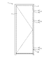
本実施形態の扉ユニット1は、図1、図2に示すように、開口縁部としての枠体2により形成される開口2aを開閉可能な扉3と、扉3を回動自在に枠体2に支持する3つの丁番10、11と、を有している。
また、抜け防止部材の挿入軸部の雄ねじを回動軸の雌ねじに螺合することで、抜け防止部材を取り付ける構成としたが、これに限ることはない。例えば、抜け防止部材の挿入軸部に雌ねじを形成し、回動軸に雄ねじを形成し、それらを螺合する構成でも良い。なお、雌ねじ、雄ねじの螺合を用いた取り付け構成ではなく、その他の係合構造を採用して抜け防止部材を取り付けても良い。
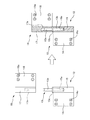
11 丁番(下丁番)、11a 丁番、12 軸側部材、13a 回動軸、
16 軸受部材、17a 孔部、19 軸側部材、22a 回動軸、22b 雌ねじ、
23 軸受部材、24a 孔部、24b 軸受部材の下端、26 軸受部材、
27a 孔部、27b 端部収容部、27c 段部、30 抜け防止部材、
31 挿入軸部、31a 雄ねじ、32 抜け防止端部、33 抜け防止部材、
33a 抜け防止端部、S 空隙、
Claims (5)
- 開口を開閉可能な扉と、
前記扉を回動自在に支持する複数の丁番と、を有し、
前記丁番は、
前記開口を形成する開口縁部と前記扉とのうちの一方に固定されて回動軸を備えた軸側部材と、
前記開口縁部と前記扉とのうちの他方に固定され、前記回動軸が挿入される孔部を備えた軸受部材と、を有し、
前記回動軸が前記孔部に挿入された状態にて、前記扉に固定された前記軸側部材又は前記軸受部材が、前記開口縁部に固定された前記軸受部材又は前記軸側部材の上方に配置されており、
前記複数の丁番のうちの少なくとも1つは、前記軸側部材が前記扉に固定され、前記軸受部材が前記開口縁部に固定され、且つ、挿入された前記回動軸が前記孔部から抜けることを防止する抜け防止部材が設けられており、
前記抜け防止部材が設けられた前記丁番の前記回動軸は、先端に雌ねじが形成されており、
前記抜け防止部材は、先端に前記雌ねじに螺合される雄ねじが形成された軸部と、前記軸部の後端に形成され前記孔部の直径より大きなサイズの抜け防止端部と、を有し、
前記抜け防止部材の前記軸部の雄ねじが前記軸側部材の雌ねじに螺着され、
前記抜け防止部材の前記軸部の雄ねじが前記軸側部材の雌ねじに螺着された状態で、前記回動軸の軸方向における前記軸受部材と前記抜け防止端部との間に空隙を有することを特徴とする扉ユニット。 - 請求項1に記載の扉ユニットであって、
前記抜け防止部材が設けられた前記丁番の前記軸側部材は、前記軸受部材に対して、前記回動軸の軸方向に移動可能であることを特徴とする扉ユニット。 - 請求項1または請求項2に記載の扉ユニットであって、
前記抜け防止部材は、前記複数の丁番のうちの最も下に位置する最下丁番に設けられていることを特徴とする扉ユニット。 - 請求項1乃至請求項3のいずれかに記載の扉ユニットであって、
前記軸受部材は、前記孔部と繋がって設けられ前記孔部より直径が大きく、前記抜け防止部材の前記雄ねじが前記軸側部材の前記雌ねじに螺着されて前記抜け防止端部が収容される端部収容部を有しており、
前記空隙は、前記端部収容部内に設けられることを特徴とする扉ユニット。 - 請求項1乃至請求項4のいずれかに記載の扉ユニットであって、
前記抜け防止部材は、前記複数の丁番のうちの最も下に位置する最下丁番に設けられ、
前記複数の丁番のうちの最も上に位置する最上丁番は、前記軸側部材が前記開口縁部に固定され、前記軸受部材が前記扉に固定されていることを特徴とする扉ユニット。
Priority Applications (1)
| Application Number | Priority Date | Filing Date | Title |
|---|---|---|---|
| JP2013229046A JP6301110B2 (ja) | 2013-11-05 | 2013-11-05 | 扉ユニット |
Applications Claiming Priority (1)
| Application Number | Priority Date | Filing Date | Title |
|---|---|---|---|
| JP2013229046A JP6301110B2 (ja) | 2013-11-05 | 2013-11-05 | 扉ユニット |
Publications (2)
| Publication Number | Publication Date |
|---|---|
| JP2015089997A JP2015089997A (ja) | 2015-05-11 |
| JP6301110B2 true JP6301110B2 (ja) | 2018-03-28 |
Family
ID=53193672
Family Applications (1)
| Application Number | Title | Priority Date | Filing Date |
|---|---|---|---|
| JP2013229046A Active JP6301110B2 (ja) | 2013-11-05 | 2013-11-05 | 扉ユニット |
Country Status (1)
| Country | Link |
|---|---|
| JP (1) | JP6301110B2 (ja) |
Families Citing this family (2)
| Publication number | Priority date | Publication date | Assignee | Title |
|---|---|---|---|---|
| JP7050660B2 (ja) * | 2018-12-27 | 2022-04-08 | 株式会社クボタ | コンバイン |
| CN114109222B (zh) * | 2021-11-27 | 2023-04-28 | 红旗集团温州变压器有限公司 | 一种高低压成套开关设备 |
Family Cites Families (8)
| Publication number | Priority date | Publication date | Assignee | Title |
|---|---|---|---|---|
| JPS59146477U (ja) * | 1983-03-18 | 1984-09-29 | 福井 亀之助 | 左右兼用蝶番 |
| JPS60161265U (ja) * | 1984-04-04 | 1985-10-26 | ワイケイケイ株式会社 | ドア用ヒンジ装置 |
| US5263227A (en) * | 1992-05-18 | 1993-11-23 | General Motors Corporation | Single hung self aligning door hinge |
| CA2354796A1 (en) * | 2001-08-02 | 2003-02-02 | Multimatic Inc. | Automotive door hinge with structural integrated pivot |
| JP4821273B2 (ja) * | 2005-11-04 | 2011-11-24 | パナソニック電工株式会社 | 蝶番 |
| JP4846387B2 (ja) * | 2006-02-23 | 2011-12-28 | 文化シヤッター株式会社 | 扉装置 |
| US20080235907A1 (en) * | 2007-03-27 | 2008-10-02 | Adc Telecommunications, Inc. | Multi-functional hinge |
| CA2639243A1 (en) * | 2007-08-31 | 2009-02-28 | Bush Industries, Inc. | Hinge with locking tab |
-
2013
- 2013-11-05 JP JP2013229046A patent/JP6301110B2/ja active Active
Also Published As
| Publication number | Publication date |
|---|---|
| JP2015089997A (ja) | 2015-05-11 |
Similar Documents
| Publication | Publication Date | Title |
|---|---|---|
| JP6062164B2 (ja) | ヒンジ装置 | |
| US10506890B2 (en) | Cup holder | |
| JP6301110B2 (ja) | 扉ユニット | |
| JP2010127477A (ja) | 冷蔵庫 | |
| WO2015107721A1 (ja) | 航空機の乗客用シートの収納ユニット | |
| KR20130072418A (ko) | 공작기계용 도어의 자동 개폐장치 | |
| JP6401385B2 (ja) | 回転式ドア用ドアヒンジの高さ調節装置 | |
| JP4217674B2 (ja) | 冷蔵庫扉の開閉構造 | |
| KR101392369B1 (ko) | 안전도어 | |
| KR20100138293A (ko) | 회동식 창호용 스테이바 | |
| JP4912272B2 (ja) | 電気電子機器収納用キャビネット | |
| JP2007270557A (ja) | 扉開閉装置 | |
| KR200447878Y1 (ko) | 폴딩도어의 이동안내장치 | |
| JP4917146B2 (ja) | エレベータ制御盤 | |
| KR102520553B1 (ko) | 도어용 손끼임방지 경첩 | |
| JP7305477B2 (ja) | ブース用の折戸 | |
| KR102616278B1 (ko) | 도어 결합 장치 | |
| JP6585004B2 (ja) | 建具 | |
| CN101818613B (zh) | 一种垂帘 | |
| JP6168075B2 (ja) | 壁構造 | |
| JP2016108788A5 (ja) | グレビティヒンジ | |
| JP3099809U (ja) | スライド・スイング式安全カバー付きドア装置 | |
| KR20160040843A (ko) | 차량용 도어의 픽스드글라스와 디비전채널 결합 구조 | |
| JP2015081479A (ja) | 扉の片下がり防止構造を備えたキャビネット | |
| JP2015160047A (ja) | 遊技機 |
Legal Events
| Date | Code | Title | Description |
|---|---|---|---|
| A621 | Written request for application examination |
Free format text: JAPANESE INTERMEDIATE CODE: A621 Effective date: 20160818 |
|
| A977 | Report on retrieval |
Free format text: JAPANESE INTERMEDIATE CODE: A971007 Effective date: 20170529 |
|
| A131 | Notification of reasons for refusal |
Free format text: JAPANESE INTERMEDIATE CODE: A131 Effective date: 20170606 |
|
| A521 | Request for written amendment filed |
Free format text: JAPANESE INTERMEDIATE CODE: A523 Effective date: 20170626 |
|
| A131 | Notification of reasons for refusal |
Free format text: JAPANESE INTERMEDIATE CODE: A131 Effective date: 20170822 |
|
| A521 | Request for written amendment filed |
Free format text: JAPANESE INTERMEDIATE CODE: A523 Effective date: 20171005 |
|
| TRDD | Decision of grant or rejection written | ||
| A01 | Written decision to grant a patent or to grant a registration (utility model) |
Free format text: JAPANESE INTERMEDIATE CODE: A01 Effective date: 20180227 |
|
| A61 | First payment of annual fees (during grant procedure) |
Free format text: JAPANESE INTERMEDIATE CODE: A61 Effective date: 20180228 |
|
| R150 | Certificate of patent or registration of utility model |
Ref document number: 6301110 Country of ref document: JP Free format text: JAPANESE INTERMEDIATE CODE: R150 |
|
| R250 | Receipt of annual fees |
Free format text: JAPANESE INTERMEDIATE CODE: R250 |