JP6284807B2 - 駆動装置 - Google Patents
駆動装置 Download PDFInfo
- Publication number
- JP6284807B2 JP6284807B2 JP2014074911A JP2014074911A JP6284807B2 JP 6284807 B2 JP6284807 B2 JP 6284807B2 JP 2014074911 A JP2014074911 A JP 2014074911A JP 2014074911 A JP2014074911 A JP 2014074911A JP 6284807 B2 JP6284807 B2 JP 6284807B2
- Authority
- JP
- Japan
- Prior art keywords
- rotor
- gap
- motor
- eccentric
- crankshaft
- Prior art date
- Legal status (The legal status is an assumption and is not a legal conclusion. Google has not performed a legal analysis and makes no representation as to the accuracy of the status listed.)
- Active
Links
- 239000003638 chemical reducing agent Substances 0.000 claims description 23
- 230000008859 change Effects 0.000 claims description 18
- 238000004804 winding Methods 0.000 description 11
- 239000000969 carrier Substances 0.000 description 7
- 230000001681 protective effect Effects 0.000 description 5
- 230000000694 effects Effects 0.000 description 4
- 238000000034 method Methods 0.000 description 4
- 230000010349 pulsation Effects 0.000 description 4
- 230000005540 biological transmission Effects 0.000 description 3
- 230000033001 locomotion Effects 0.000 description 3
- 230000009467 reduction Effects 0.000 description 3
- 230000009471 action Effects 0.000 description 2
- 230000007423 decrease Effects 0.000 description 2
- 239000000428 dust Substances 0.000 description 2
- 239000000853 adhesive Substances 0.000 description 1
- 230000001070 adhesive effect Effects 0.000 description 1
- 238000005452 bending Methods 0.000 description 1
- 230000008901 benefit Effects 0.000 description 1
- 230000006872 improvement Effects 0.000 description 1
- 239000000463 material Substances 0.000 description 1
- 230000004048 modification Effects 0.000 description 1
- 238000012986 modification Methods 0.000 description 1
- 230000010355 oscillation Effects 0.000 description 1
- 230000010363 phase shift Effects 0.000 description 1
- 230000001360 synchronised effect Effects 0.000 description 1
Images
Landscapes
- Retarders (AREA)
- Connection Of Motors, Electrical Generators, Mechanical Devices, And The Like (AREA)
Description
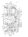
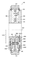
10…減速機
12…内歯歯車
14、16…外歯歯車
18…入力軸(クランク軸)
20、22…偏心体
24、26…キャリヤ
30…モータ
40…ロータ
50…ステータ
Claims (9)
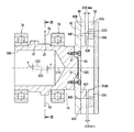
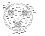
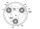
- モータと、偏心体が設けられたクランク軸を有する偏心揺動型の減速機と、を備えた駆動装置において、
前記モータが、前記クランク軸に設けられ、該クランク軸と一体的に回転するロータと、該ロータとの間にギャップを設けて配置されるステータと、を有し、
前記モータは、前記ロータと前記ステータとが、軸方向に前記ギャップを設けて対向するアキシャルギャップ型のモータであり、
前記クランク軸は、前記ロータよりも前記偏心体側においてのみ軸受により支持され、
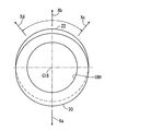
前記クランク軸が変形していない状態において、前記モータに通電したときの前記ロータと前記ステータとの間に発生する吸引力を、最外周を含む同一の径方向位置において、周方向位置によって異ならせた
ことを特徴とする駆動装置。 - 請求項1において、
前記モータに通電していない状態において、前記ギャップが最外周を含む同一の径方向位置において、周方向位置によって異なる
ことを特徴とする駆動装置。 - 請求項2において、
前記軸受は、前記ロータに最も近い前記偏心体と前記ロータの間に配置され、
前記ロータに最も近い前記偏心体の最大偏心方向における前記ギャップが、該偏心体の反最大偏心方向における前記ギャップよりも小さい
ことを特徴とする駆動装置。 - 請求項2または3において、
前記ギャップが、同一の周方向位置において、径方向位置によっても異なる
ことを特徴とする駆動装置。 - 請求項4において、
前記軸受は、前記ロータに最も近い前記偏心体と前記ロータの間に配置され、
前記ギャップが、同一の周方向位置において、前記最大偏心方向から反最大偏心方向に向かって大きくなる
ことを特徴とする駆動装置。 - 請求項2〜5のいずれかにおいて、
前記ロータは、ベースプレートと、前記ベースプレートの表面に配置された永久磁石と、を有し、
前記ベースプレートの軸方向厚さを周方向位置によって異ならせることにより、前記ギャップが最外周を含む同一の径方向位置において、周方向位置によって異なる
ことを特徴とする駆動装置。 - 請求項1〜6のいずれかにおいて、
前記モータとして、第1、第2のアキシャルギャップ型のモータを有し、
前記クランク軸の一端に、前記第1のアキシャルギャップ型のモータのロータ、他端に前記第2のアキシャルギャップ型のモータのロータが設けられ、
前記第2のアキシャルギャップ型のモータにおける前記ギャップの周方向の変化態様は、前記第1のアキシャルギャップ型のモータにおける前記ギャップの周方向の変化態様を、前記クランク軸の軸心を通る面に対して折り返したものである
ことを特徴とする駆動装置。 - 請求項1〜7のいずれかにおいて、
前記ロータによって形成される磁界が、該ロータの周方向位置によって異なる
ことを特徴とする駆動装置。 - モータと、偏心体が設けられたクランク軸を有する偏心揺動型の減速機と、を備えた駆動装置において、
前記モータが、前記クランク軸に設けられ、該クランク軸と一体的に回転するロータと、該ロータとの間にギャップを設けて配置されるステータと、を有し、
前記モータは、前記ロータと前記ステータとが、軸方向に前記ギャップを設けて対向するアキシャルギャップ型のモータであり、
前記クランク軸は、前記ロータよりも前記偏心体側においてのみ軸受により支持され、
前記モータに通電していない状態において、前記ギャップが最外周を含む同一の径方向位置において、周方向位置によって異なる
ことを特徴とする駆動装置。
Priority Applications (1)
| Application Number | Priority Date | Filing Date | Title |
|---|---|---|---|
| JP2014074911A JP6284807B2 (ja) | 2014-03-31 | 2014-03-31 | 駆動装置 |
Applications Claiming Priority (1)
| Application Number | Priority Date | Filing Date | Title |
|---|---|---|---|
| JP2014074911A JP6284807B2 (ja) | 2014-03-31 | 2014-03-31 | 駆動装置 |
Publications (2)
| Publication Number | Publication Date |
|---|---|
| JP2015198498A JP2015198498A (ja) | 2015-11-09 |
| JP6284807B2 true JP6284807B2 (ja) | 2018-02-28 |
Family
ID=54547921
Family Applications (1)
| Application Number | Title | Priority Date | Filing Date |
|---|---|---|---|
| JP2014074911A Active JP6284807B2 (ja) | 2014-03-31 | 2014-03-31 | 駆動装置 |
Country Status (1)
| Country | Link |
|---|---|
| JP (1) | JP6284807B2 (ja) |
Families Citing this family (1)
| Publication number | Priority date | Publication date | Assignee | Title |
|---|---|---|---|---|
| JP6877318B2 (ja) * | 2017-11-14 | 2021-05-26 | 住友重機械工業株式会社 | ギヤモータ |
Family Cites Families (4)
| Publication number | Priority date | Publication date | Assignee | Title |
|---|---|---|---|---|
| JPS5022206A (ja) * | 1973-07-04 | 1975-03-10 | ||
| JPS639253Y2 (ja) * | 1981-01-22 | 1988-03-18 | ||
| JP2509108Y2 (ja) * | 1990-11-27 | 1996-08-28 | 住友重機械工業株式会社 | 内接噛合遊星歯車構造 |
| JP5812802B2 (ja) * | 2011-10-27 | 2015-11-17 | ナブテスコ株式会社 | 駆動装置 |
-
2014
- 2014-03-31 JP JP2014074911A patent/JP6284807B2/ja active Active
Also Published As
| Publication number | Publication date |
|---|---|
| JP2015198498A (ja) | 2015-11-09 |
Similar Documents
| Publication | Publication Date | Title |
|---|---|---|
| CN108291612A (zh) | 带有电动机的减速机 | |
| JP5801688B2 (ja) | 駆動装置 | |
| US10619706B2 (en) | Speed reducer and motor with speed reducer | |
| CN109114173B (zh) | 具动力源的减速装置 | |
| JPWO2020050242A1 (ja) | 駆動装置 | |
| TWI577904B (zh) | 驅動裝置 | |
| JP6284807B2 (ja) | 駆動装置 | |
| JP2019092272A (ja) | ギヤモータ | |
| JP2015140910A (ja) | 駆動ユニット | |
| JP2014214834A (ja) | 減速機 | |
| JP2017025979A (ja) | 揺動許容の連結機構及び内接式遊星歯車装置 | |
| JP6427470B2 (ja) | 可変ギャップ式モータ | |
| JP6029273B2 (ja) | 歯車伝動装置 | |
| CN103532298B (zh) | 四转子驱动式啮合电动机 | |
| JP2019035500A (ja) | 減速機及び減速機付きモータ | |
| JP3694251B2 (ja) | 減速機構を備えた誘導子型回転電機 | |
| JP2004215397A (ja) | ステッピングモータ | |
| CN104935132B (zh) | 一种双啮合永磁式电动机 | |
| JP2022103575A (ja) | モータ付き減速機、減速装置、ロボット、および移動体 | |
| JP2020067032A (ja) | 真空ポンプおよび真空ポンプの製造方法 | |
| JP2007288949A (ja) | 減速機内蔵電動機 | |
| JPWO1986005634A1 (ja) | ギヤドモ−タ | |
| JP2013083298A (ja) | 駆動ユニット |
Legal Events
| Date | Code | Title | Description |
|---|---|---|---|
| A621 | Written request for application examination |
Free format text: JAPANESE INTERMEDIATE CODE: A621 Effective date: 20160915 |
|
| A977 | Report on retrieval |
Free format text: JAPANESE INTERMEDIATE CODE: A971007 Effective date: 20170622 |
|
| A131 | Notification of reasons for refusal |
Free format text: JAPANESE INTERMEDIATE CODE: A131 Effective date: 20170704 |
|
| A521 | Written amendment |
Free format text: JAPANESE INTERMEDIATE CODE: A523 Effective date: 20170831 |
|
| RD03 | Notification of appointment of power of attorney |
Free format text: JAPANESE INTERMEDIATE CODE: A7423 Effective date: 20170914 |
|
| TRDD | Decision of grant or rejection written | ||
| A01 | Written decision to grant a patent or to grant a registration (utility model) |
Free format text: JAPANESE INTERMEDIATE CODE: A01 Effective date: 20180130 |
|
| A61 | First payment of annual fees (during grant procedure) |
Free format text: JAPANESE INTERMEDIATE CODE: A61 Effective date: 20180131 |
|
| R150 | Certificate of patent or registration of utility model |
Ref document number: 6284807 Country of ref document: JP Free format text: JAPANESE INTERMEDIATE CODE: R150 |