JP6271069B1 - 固液分離装置 - Google Patents
固液分離装置 Download PDFInfo
- Publication number
- JP6271069B1 JP6271069B1 JP2017151672A JP2017151672A JP6271069B1 JP 6271069 B1 JP6271069 B1 JP 6271069B1 JP 2017151672 A JP2017151672 A JP 2017151672A JP 2017151672 A JP2017151672 A JP 2017151672A JP 6271069 B1 JP6271069 B1 JP 6271069B1
- Authority
- JP
- Japan
- Prior art keywords
- screw
- pipe member
- processed
- solid
- supply port
- Prior art date
- Legal status (The legal status is an assumption and is not a legal conclusion. Google has not performed a legal analysis and makes no representation as to the accuracy of the status listed.)
- Active
Links
Images


Classifications
-
- B—PERFORMING OPERATIONS; TRANSPORTING
- B30—PRESSES
- B30B—PRESSES IN GENERAL
- B30B9/00—Presses specially adapted for particular purposes
- B30B9/02—Presses specially adapted for particular purposes for squeezing-out liquid from liquid-containing material, e.g. juice from fruits, oil from oil-containing material
- B30B9/12—Presses specially adapted for particular purposes for squeezing-out liquid from liquid-containing material, e.g. juice from fruits, oil from oil-containing material using pressing worms or screws co-operating with a permeable casing
- B30B9/14—Presses specially adapted for particular purposes for squeezing-out liquid from liquid-containing material, e.g. juice from fruits, oil from oil-containing material using pressing worms or screws co-operating with a permeable casing operating with only one screw or worm
-
- B—PERFORMING OPERATIONS; TRANSPORTING
- B30—PRESSES
- B30B—PRESSES IN GENERAL
- B30B9/00—Presses specially adapted for particular purposes
- B30B9/02—Presses specially adapted for particular purposes for squeezing-out liquid from liquid-containing material, e.g. juice from fruits, oil from oil-containing material
- B30B9/12—Presses specially adapted for particular purposes for squeezing-out liquid from liquid-containing material, e.g. juice from fruits, oil from oil-containing material using pressing worms or screws co-operating with a permeable casing
- B30B9/121—Screw constructions
-
- B—PERFORMING OPERATIONS; TRANSPORTING
- B01—PHYSICAL OR CHEMICAL PROCESSES OR APPARATUS IN GENERAL
- B01D—SEPARATION
- B01D33/00—Filters with filtering elements which move during the filtering operation
-
- B—PERFORMING OPERATIONS; TRANSPORTING
- B01—PHYSICAL OR CHEMICAL PROCESSES OR APPARATUS IN GENERAL
- B01D—SEPARATION
- B01D29/00—Filters with filtering elements stationary during filtration, e.g. pressure or suction filters, not covered by groups B01D24/00 - B01D27/00; Filtering elements therefor
- B01D29/11—Filters with filtering elements stationary during filtration, e.g. pressure or suction filters, not covered by groups B01D24/00 - B01D27/00; Filtering elements therefor with bag, cage, hose, tube, sleeve or like filtering elements
- B01D29/31—Self-supporting filtering elements
- B01D29/35—Self-supporting filtering elements arranged for outward flow filtration
-
- B—PERFORMING OPERATIONS; TRANSPORTING
- B01—PHYSICAL OR CHEMICAL PROCESSES OR APPARATUS IN GENERAL
- B01D—SEPARATION
- B01D29/00—Filters with filtering elements stationary during filtration, e.g. pressure or suction filters, not covered by groups B01D24/00 - B01D27/00; Filtering elements therefor
- B01D29/44—Edge filtering elements, i.e. using contiguous impervious surfaces
- B01D29/46—Edge filtering elements, i.e. using contiguous impervious surfaces of flat, stacked bodies
-
- B—PERFORMING OPERATIONS; TRANSPORTING
- B01—PHYSICAL OR CHEMICAL PROCESSES OR APPARATUS IN GENERAL
- B01D—SEPARATION
- B01D29/00—Filters with filtering elements stationary during filtration, e.g. pressure or suction filters, not covered by groups B01D24/00 - B01D27/00; Filtering elements therefor
- B01D29/62—Regenerating the filter material in the filter
- B01D29/64—Regenerating the filter material in the filter by scrapers, brushes, nozzles, or the like, acting on the cake side of the filtering element
- B01D29/6469—Regenerating the filter material in the filter by scrapers, brushes, nozzles, or the like, acting on the cake side of the filtering element scrapers
- B01D29/6476—Regenerating the filter material in the filter by scrapers, brushes, nozzles, or the like, acting on the cake side of the filtering element scrapers with a rotary movement with respect to the filtering element
-
- B—PERFORMING OPERATIONS; TRANSPORTING
- B01—PHYSICAL OR CHEMICAL PROCESSES OR APPARATUS IN GENERAL
- B01D—SEPARATION
- B01D29/00—Filters with filtering elements stationary during filtration, e.g. pressure or suction filters, not covered by groups B01D24/00 - B01D27/00; Filtering elements therefor
- B01D29/76—Handling the filter cake in the filter for purposes other than for regenerating
- B01D29/80—Handling the filter cake in the filter for purposes other than for regenerating for drying
- B01D29/82—Handling the filter cake in the filter for purposes other than for regenerating for drying by compression
- B01D29/828—Handling the filter cake in the filter for purposes other than for regenerating for drying by compression using screws
-
- B—PERFORMING OPERATIONS; TRANSPORTING
- B30—PRESSES
- B30B—PRESSES IN GENERAL
- B30B15/00—Details of, or accessories for, presses; Auxiliary measures in connection with pressing
-
- B—PERFORMING OPERATIONS; TRANSPORTING
- B30—PRESSES
- B30B—PRESSES IN GENERAL
- B30B15/00—Details of, or accessories for, presses; Auxiliary measures in connection with pressing
- B30B15/32—Discharging presses
Landscapes
- Chemical & Material Sciences (AREA)
- Chemical Kinetics & Catalysis (AREA)
- Engineering & Computer Science (AREA)
- Mechanical Engineering (AREA)
- Treatment Of Sludge (AREA)
- Filtration Of Liquid (AREA)
- Centrifugal Separators (AREA)
Abstract
【解決手段】このスクリュ式濃縮装置(固液分離装置)100は、回転軸21を含み、供給された被処理物を回転軸21の回転に伴い送るスクリュ2と、スクリュ2の一端近傍に設けられる被処理物の主供給口11aと、スクリュ2の他端近傍に設けられる被処理物の排出口71と、回転軸21を回転させるモータ8と、スクリュ2を取り囲むように配置された複数の固定板31と、隣接する固定板31の間に配置された可動板33とを含み、隣接する固定板31間にろ過溝Sが形成された積層状ろ体3と、被処理物の副供給口42aを含み、積層状ろ体3の途中に配置される筒形状の第1パイプ部材4と、を備える。
【選択図】図1
Description
図1〜図6を参照して、本発明の第1実施形態について説明する。
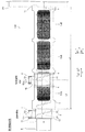
本発明の第1実施形態によるスクリュ式濃縮装置100は、図1に示すように、被処理物の主供給口11aを含む供給部材1と、スクリュ2と、積層状ろ体3と、被処理物の副供給口42aを含む第1パイプ部材4と、第1パイプ部材4の後述するX方向の両端にそれぞれ設けられるフランジ5およびフランジ6と、被処理物の排出口71を含む外枠7と、モータ8と、を備えている。スクリュ2は、直線状に延びる棒状の回転軸21を含んでいる。回転軸21は、略水平方向に延びている。スクリュ式濃縮装置100は、特許請求の範囲の「固液分離装置」の一例である。主供給口11aは、特許請求の範囲の「主被処理物供給口」の一例である。副供給口42aは、特許請求の範囲の「副被処理物供給口」の一例である。モータ8は、特許請求の範囲の「駆動部」の一例である。
図1に示すように、供給部材1は、中空の管状の部材である。具体的には、供給部材1は、上端に主供給口11aが設けられ、上下方向(Z方向)に延びる円筒形状の第1部分11と、第1部分11の下端に一体的に接続され、X1方向側が開放された第2部分12とを含んでいる。主供給口11aは、スクリュ2のX2方向側の端部近傍に設けられている。第2部分12の内側には、スクリュ2のX2方向側の端部が配置されている。供給部材1のX2方向側には、モータ8が配置されている。
図1に示すように、スクリュ2は、回転軸21と、羽根部22とを含んでいる。回転軸21は、第2部分12をX方向に貫通している。スクリュ2は、回転軸21のX2方向端部においてモータ8に接続され、モータ8から駆動力を得て回転するように構成されている。スクリュ2は、回転軸21の回転に伴って羽根部22を回転させることにより、主供給口11aから供給された被処理物を、X1方向(回転体式脱水装置101側)に送るように構成されている。また、回転軸21は、スクリュ式濃縮装置100と回転体式脱水装置101とが並ぶ方向(A方向)に延びている。
図1に示すように、積層状ろ体3は、全体として、スクリュ2を取り囲むようにスクリュ2を内側に配置するとともに、X方向に延びる筒形状を有している。
図2に示すように、固定板31は、X方向に略直交する方向に延びる円環形状を有している。すなわち、固定板31は、中心に固定板31をX方向に貫通する円形状の貫通穴31aを有している。なお、固定板31は、動くことがないように、固定板31の外縁部の複数箇所に接触する外枠7により、固定されている。
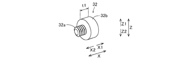
図3に示すように、スペーサ32は、X方向に延びる雄ネジ部32aと、X1方向側から雄ネジ部32aの一端を支持する柱形状の本体部32bとを有している。本体部32bは、X方向において厚みt1を有している。
図2に示すように、可動板33は、X方向に略直交する方向に延びる円環形状を有している。すなわち、可動板33は、中心に固定板31をX方向に貫通する円形状の貫通穴33aを有している。
図2に示すように、隣接する固定板31間には、スペーサ32により、隙間t1のろ過溝Sが形成されている。また、X方向において、隣接する固定板31間のろ過溝Sの可動板33を除く部分には、隙間(t1−t2)のろ水流出溝Gが形成されている。ろ水流出溝Gとは、X方向に隣接して配置される2つの固定板31と、可動板33との間の隙間部分である。
図1に示すように、第1パイプ部材4は、概して、筒形状を有する部材であり、積層状ろ体3の途中において、スクリュ式濃縮装置100に追加で被処理物を供給するための部材である。このため、第1パイプ部材4は、積層状ろ体3の途中に設けられている。
図4に示すように、フランジ5とフランジ6とは、ともに円環形状を有しており、互いに同一形状を有している。すなわち、フランジ5とフランジ6とは、一対の構成である。フランジ5とフランジ6とは、回転軸21の軸方向(X方向)の両側から第1パイプ部材4を接触状態で挟み込んでいる。
図2に示すように、フランジ5は、第1パイプ部材4のX2方向側に配置されている。フランジ5の外径(X方向に直交する方向の大きさ)は、第1パイプ部材4の第1部分41の外径よりも大きい。
図2に示すように、フランジ6は、上記の通り、フランジ5と同一形状を有しているため、以下では、フランジ5と異なる点について説明する。
図1に示すように、外枠7は、積層状ろ体3を外側から取り囲む骨組み構造を有している。外枠7は、固定板31の外縁部と、フランジ5の凸部53の接触面53aと、フランジ6の凸部63の接触面63aとに接触することにより、積層状ろ体3と、フランジ5と、フランジ6と、フランジ5およびフランジ6とが固定されている第1パイプ部材4とを互いに固定している。また、外枠7のX1方向の端部(スクリュ2のX1方向の端部近傍)には、被処理物をスクリュ式濃縮装置100から排出する排出口71が設けられている。排出口71から排出された被処理物は、回転体式脱水装置101に供給される。
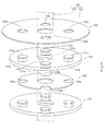
回転体式脱水装置101は、図5に示すように、複数の回転体102と、回転体102を駆動させるモータ(図示せず)とを備えている。
第1実施形態では、以下のような効果を得ることができる。
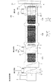
次に、図7を参照して、本発明の第2実施形態について説明する。この第2実施形態では、第1パイプ部材4を備える上記第1実施形態の構成に加えて、第2パイプ部材204を備える例について説明する。
図7に示すように、第2実施形態によるスクリュ式濃縮装置200は、第2パイプ部材204と、第2パイプ部材204のX方向の両端にそれぞれ設けられるフランジ205およびフランジ206とを備えている。なお、スクリュ式濃縮装置200は、特許請求の範囲の「固液分離装置」の一例である。
第2実施形態では、以下のような効果を得ることができる。
次に、図8を参照して、本発明の第3実施形態について説明する。この第3実施形態では、被処理物の濃縮処理を行うスクリュ式濃縮装置100が、第1パイプ部材4を備える上記第1実施形態とは異なり、被処理物の脱水処理を行うスクリュ式脱水装置300が、第1パイプ部材4を備える例について説明する。なお、スクリュ式脱水装置300は、特許請求の範囲の「固液分離装置」の一例である。
図8に示すように、第3実施形態によるスクリュ式脱水装置300は、スクリュ302と、背圧板9とを備えている。
第3実施形態では、以下のような効果を得ることができる。
なお、今回開示された実施形態は、すべての点で例示であって制限的なものではないと考えられるべきである。本発明の範囲は、上記した実施形態の説明ではなく特許請求の範囲によって示され、さらに特許請求の範囲と均等の意味および範囲内でのすべての変更(変形例)が含まれる。
3 積層状ろ体
4 第1パイプ部材
5、6、205、206 フランジ
8 モータ(駆動部)
11a 主供給口(主被処理物供給口)
21 回転軸
31 固定板
33 可動板
41 第1部分
42 第2部分
42a 副供給口(副被処理物供給口)
71 排出口
100、200 スクリュ式濃縮装置(固液分離装置)
204 第2パイプ部材
204a 補助供給口
300 スクリュ式脱水装置(固液分離装置)
R 撹拌領域
S ろ過溝
Claims (8)
- 回転軸を含み、供給された被処理物を前記回転軸の回転に伴い送るスクリュと、
前記スクリュの一端近傍に設けられる被処理物の主被処理物供給口と、
前記スクリュの他端近傍に設けられる被処理物の排出口と、
前記回転軸を回転させる駆動部と、
前記スクリュを取り囲むように配置された複数の固定板と、隣接する前記固定板の間に配置された可動板とを含み、隣接する前記固定板間にろ過溝が形成された積層状ろ体と、
被処理物の副被処理物供給口を含み、前記積層状ろ体の途中に配置される筒形状の第1パイプ部材と、を備える、固液分離装置。 - 前記副被処理物供給口の開口面積は、前記主被処理物供給口の開口面積以上である、請求項1に記載の固液分離装置。
- 前記第1パイプ部材を、前記回転軸の軸方向の両側から接触状態で挟み込む一対のフランジをさらに備える、請求項1または2に記載の固液分離装置。
- 前記一対のフランジの一方は、前記固定板に対向して配置され、
前記一対のフランジの他方は、前記可動板に対向して配置されている、請求項3に記載の固液分離装置。 - 前記第1パイプ部材は、前記回転軸の軸方向に延びる筒形状の第1部分と、前記副被処理物供給口が設けられ、前記第1部分の外表面から前記軸方向に交差する方向へ突出して延びる筒形状の第2部分とを一体的に含む、請求項1〜4のいずれか1項に記載の固液分離装置。
- 前記第1パイプ部材に加えて、凝集剤または洗浄水の補助供給口を含み、前記積層状ろ体の途中に配置される筒形状の第2パイプ部材を備える、請求項1〜5のいずれか1項に記載の固液分離装置。
- 前記第2パイプ部材は、凝集剤を供給する前記補助供給口を含み、前記排出口側の前記回転軸の端部近傍に配置され、
前記第2パイプ部材の前記排出口側には、前記スクリュにより被処理物を撹拌する撹拌領域が設けられている、請求項6に記載の固液分離装置。 - 前記第1パイプ部材は、前記回転軸の軸方向において、前記積層状ろ体の全長の3分の1以上2分の1以下の距離だけ、前記積層状ろ体の前記主被処理物供給口側の端部から離間した位置に配置されている、請求項1〜7のいずれか1項に記載の固液分離装置。
Priority Applications (6)
| Application Number | Priority Date | Filing Date | Title |
|---|---|---|---|
| JP2017151672A JP6271069B1 (ja) | 2017-08-04 | 2017-08-04 | 固液分離装置 |
| EP18185998.4A EP3437708B1 (en) | 2017-08-04 | 2018-07-27 | Solid-liquid separator |
| HUE18185998A HUE051117T2 (hu) | 2017-08-04 | 2018-07-27 | Szilárdanyag-folyadék szeparátor |
| RU2018127780A RU2687442C1 (ru) | 2017-08-04 | 2018-07-30 | Сепаратор жидкой и твердой фаз |
| UAA201808430A UA122706C2 (uk) | 2017-08-04 | 2018-08-03 | Сепаратор рідкої та твердої фаз |
| CN201810875489.5A CN109383066B (zh) | 2017-08-04 | 2018-08-03 | 固液分离装置 |
Applications Claiming Priority (1)
| Application Number | Priority Date | Filing Date | Title |
|---|---|---|---|
| JP2017151672A JP6271069B1 (ja) | 2017-08-04 | 2017-08-04 | 固液分離装置 |
Publications (2)
| Publication Number | Publication Date |
|---|---|
| JP6271069B1 true JP6271069B1 (ja) | 2018-01-31 |
| JP2019030825A JP2019030825A (ja) | 2019-02-28 |
Family
ID=61074826
Family Applications (1)
| Application Number | Title | Priority Date | Filing Date |
|---|---|---|---|
| JP2017151672A Active JP6271069B1 (ja) | 2017-08-04 | 2017-08-04 | 固液分離装置 |
Country Status (6)
| Country | Link |
|---|---|
| EP (1) | EP3437708B1 (ja) |
| JP (1) | JP6271069B1 (ja) |
| CN (1) | CN109383066B (ja) |
| HU (1) | HUE051117T2 (ja) |
| RU (1) | RU2687442C1 (ja) |
| UA (1) | UA122706C2 (ja) |
Families Citing this family (4)
| Publication number | Priority date | Publication date | Assignee | Title |
|---|---|---|---|---|
| JP7127593B2 (ja) * | 2019-03-28 | 2022-08-30 | 株式会社鶴見製作所 | 脱水機および脱水システム |
| JP7438480B2 (ja) * | 2019-11-22 | 2024-02-27 | 阿部 荒喜 | 多列多段集塵機 |
| CN113370419B (zh) * | 2021-08-02 | 2022-04-26 | 浙江优为新材料有限公司 | 一种超支化树脂改性净味光固化管道修复材料加工装置 |
| CN118578707B (zh) * | 2024-08-06 | 2024-10-01 | 山东创脂生物科技有限公司 | 一种饲料用油脂原料生产加工装置 |
Family Cites Families (19)
| Publication number | Priority date | Publication date | Assignee | Title |
|---|---|---|---|---|
| DE2231469A1 (de) * | 1972-06-27 | 1974-03-07 | Siemens Ag | Waermeaustauscher fuer einen elektronikschrank |
| JPS5611932Y2 (ja) * | 1975-09-30 | 1981-03-18 | ||
| JPS5671600A (en) * | 1979-11-16 | 1981-06-15 | Kobe Steel Ltd | Screw press |
| JPS60147299A (ja) * | 1984-01-09 | 1985-08-03 | Ebara Infilco Co Ltd | 汚泥等の脱水方法及びその装置 |
| JPH047299A (ja) * | 1990-04-23 | 1992-01-10 | Yamazaki Mazak Corp | 立体倉庫用クレーンの制御装置 |
| JP2544995B2 (ja) * | 1990-07-09 | 1996-10-16 | 新王子製紙株式会社 | パルプスラリ―の濃縮方法 |
| JPH0710440B2 (ja) * | 1992-02-21 | 1995-02-08 | アムコン株式会社 | 固液分離装置 |
| SE507498C2 (sv) * | 1996-10-07 | 1998-06-15 | Spirac Engineering Ab | Separationsanordning försedd med transportspiral och silorgan |
| JP2003136289A (ja) * | 2001-10-31 | 2003-05-14 | Yamato:Kk | スクリュープレス脱水装置 |
| JP2003211198A (ja) * | 2002-01-18 | 2003-07-29 | Maruyama Kogyo Kk | 汚泥処理装置 |
| JP4513344B2 (ja) * | 2004-02-03 | 2010-07-28 | 栗田工業株式会社 | 汚泥脱水装置 |
| JP3565841B1 (ja) * | 2004-02-09 | 2004-09-15 | アムコン株式会社 | 固液分離装置 |
| JP3638597B1 (ja) * | 2004-08-17 | 2005-04-13 | アムコン株式会社 | 固液分離装置 |
| FR2892657B1 (fr) * | 2005-11-03 | 2009-05-01 | Shinryoku Technologies | Dispositif de compactage d'un materiau et/ou pour separer un solide et un liquide, et procede correspondant |
| JP3904590B1 (ja) * | 2006-05-22 | 2007-04-11 | アムコン株式会社 | 固液分離装置 |
| KR100981926B1 (ko) * | 2008-05-23 | 2010-09-13 | 삼창기업 주식회사 | 고 비중 침전물 수거장치를 갖춘 패들식 건조기 |
| DE102008063972A1 (de) * | 2008-12-19 | 2010-07-01 | Hochland Ag | Filter zum Einsatz in der Schmelzkäseherstellung |
| CN103895250B (zh) * | 2014-03-28 | 2016-02-10 | 北京化工大学 | 一种带齿轮泵的双螺杆破碎脱水集成处理设备 |
| RU165200U1 (ru) * | 2015-12-30 | 2016-10-10 | Цуруми Мэньюфэкчеринг Ко., Лтд. | Устройство разделения твердой и жидкой фракции |
-
2017
- 2017-08-04 JP JP2017151672A patent/JP6271069B1/ja active Active
-
2018
- 2018-07-27 EP EP18185998.4A patent/EP3437708B1/en active Active
- 2018-07-27 HU HUE18185998A patent/HUE051117T2/hu unknown
- 2018-07-30 RU RU2018127780A patent/RU2687442C1/ru active
- 2018-08-03 UA UAA201808430A patent/UA122706C2/uk unknown
- 2018-08-03 CN CN201810875489.5A patent/CN109383066B/zh active Active
Also Published As
| Publication number | Publication date |
|---|---|
| UA122706C2 (uk) | 2020-12-28 |
| EP3437708B1 (en) | 2020-07-22 |
| CN109383066A (zh) | 2019-02-26 |
| HUE051117T2 (hu) | 2021-03-01 |
| RU2687442C1 (ru) | 2019-05-13 |
| EP3437708A1 (en) | 2019-02-06 |
| JP2019030825A (ja) | 2019-02-28 |
| CN109383066B (zh) | 2020-06-26 |
Similar Documents
| Publication | Publication Date | Title |
|---|---|---|
| JP6271069B1 (ja) | 固液分離装置 | |
| CA2826439C (en) | Apparatus and method for removing finely divided solids from a liquid flow | |
| JP4051395B1 (ja) | 回転加圧脱水機 | |
| KR101552972B1 (ko) | 고액분리장치 | |
| US10913015B2 (en) | Variable geometry centrifugal basket | |
| JP2017159240A (ja) | 固液分離装置および固液分離システム | |
| TWI402094B (zh) | filter | |
| JP4702358B2 (ja) | 濃縮機構付きスクリュープレス | |
| JPH09220599A (ja) | 固液分離装置 | |
| US20240278153A1 (en) | Filtering device for plastic materials with cleaning system | |
| JP4817473B2 (ja) | 可動板分割駆動式スクリュープレス装置 | |
| JP6625255B2 (ja) | 固液分離装置および固液分離システム | |
| JP3889612B2 (ja) | スクリュー式濾過脱水装置 | |
| JP5318555B2 (ja) | 回転加圧脱水機および回転加圧脱水機による汚泥の脱水方法 | |
| JP4518501B2 (ja) | ろ過装置 | |
| JP4493030B2 (ja) | ろ過装置 | |
| JP2009022934A (ja) | ろ過装置 | |
| JP6628973B2 (ja) | 固液分離装置 | |
| KR100574674B1 (ko) | 스크류식 고액 분리장치 | |
| JP4943988B2 (ja) | ろ過装置及びろ過方法 | |
| US20230302383A1 (en) | Apparatus for continuously filtering a sludge suspension | |
| JP2019037925A (ja) | 固液分離装置および固液分離システム | |
| JP4493031B2 (ja) | ろ過装置 | |
| JP4820341B2 (ja) | ろ過装置 | |
| CN107324446A (zh) | 一种管形超声分离腔 |
Legal Events
| Date | Code | Title | Description |
|---|---|---|---|
| A621 | Written request for application examination |
Free format text: JAPANESE INTERMEDIATE CODE: A621 Effective date: 20171102 |
|
| A871 | Explanation of circumstances concerning accelerated examination |
Free format text: JAPANESE INTERMEDIATE CODE: A871 Effective date: 20171102 |
|
| A975 | Report on accelerated examination |
Free format text: JAPANESE INTERMEDIATE CODE: A971005 Effective date: 20171109 |
|
| TRDD | Decision of grant or rejection written | ||
| A01 | Written decision to grant a patent or to grant a registration (utility model) |
Free format text: JAPANESE INTERMEDIATE CODE: A01 Effective date: 20171226 |
|
| A61 | First payment of annual fees (during grant procedure) |
Free format text: JAPANESE INTERMEDIATE CODE: A61 Effective date: 20171226 |
|
| R150 | Certificate of patent or registration of utility model |
Ref document number: 6271069 Country of ref document: JP Free format text: JAPANESE INTERMEDIATE CODE: R150 |
|
| R250 | Receipt of annual fees |
Free format text: JAPANESE INTERMEDIATE CODE: R250 |
|
| R250 | Receipt of annual fees |
Free format text: JAPANESE INTERMEDIATE CODE: R250 |
|
| R250 | Receipt of annual fees |
Free format text: JAPANESE INTERMEDIATE CODE: R250 |
|
| R250 | Receipt of annual fees |
Free format text: JAPANESE INTERMEDIATE CODE: R250 |
|
| R250 | Receipt of annual fees |
Free format text: JAPANESE INTERMEDIATE CODE: R250 |