JP6257940B2 - Heat pump type vehicle air conditioning system and defrosting method thereof - Google Patents
Heat pump type vehicle air conditioning system and defrosting method thereof Download PDFInfo
- Publication number
- JP6257940B2 JP6257940B2 JP2013145648A JP2013145648A JP6257940B2 JP 6257940 B2 JP6257940 B2 JP 6257940B2 JP 2013145648 A JP2013145648 A JP 2013145648A JP 2013145648 A JP2013145648 A JP 2013145648A JP 6257940 B2 JP6257940 B2 JP 6257940B2
- Authority
- JP
- Japan
- Prior art keywords
- vehicle
- evaporator
- condenser
- outside
- refrigerant
- Prior art date
- Legal status (The legal status is an assumption and is not a legal conclusion. Google has not performed a legal analysis and makes no representation as to the accuracy of the status listed.)
- Expired - Fee Related
Links
Images


Classifications
-
- F—MECHANICAL ENGINEERING; LIGHTING; HEATING; WEAPONS; BLASTING
- F25—REFRIGERATION OR COOLING; COMBINED HEATING AND REFRIGERATION SYSTEMS; HEAT PUMP SYSTEMS; MANUFACTURE OR STORAGE OF ICE; LIQUEFACTION SOLIDIFICATION OF GASES
- F25B—REFRIGERATION MACHINES, PLANTS OR SYSTEMS; COMBINED HEATING AND REFRIGERATION SYSTEMS; HEAT PUMP SYSTEMS
- F25B41/00—Fluid-circulation arrangements
- F25B41/20—Disposition of valves, e.g. of on-off valves or flow control valves
- F25B41/24—Arrangement of shut-off valves for disconnecting a part of the refrigerant cycle, e.g. an outdoor part
-
- B—PERFORMING OPERATIONS; TRANSPORTING
- B60—VEHICLES IN GENERAL
- B60H—ARRANGEMENTS OF HEATING, COOLING, VENTILATING OR OTHER AIR-TREATING DEVICES SPECIALLY ADAPTED FOR PASSENGER OR GOODS SPACES OF VEHICLES
- B60H1/00—Heating, cooling or ventilating [HVAC] devices
- B60H1/00642—Control systems or circuits; Control members or indication devices for heating, cooling or ventilating devices
- B60H1/00735—Control systems or circuits characterised by their input, i.e. by the detection, measurement or calculation of particular conditions, e.g. signal treatment, dynamic models
- B60H1/00764—Control systems or circuits characterised by their input, i.e. by the detection, measurement or calculation of particular conditions, e.g. signal treatment, dynamic models the input being a vehicle driving condition, e.g. speed
- B60H1/00778—Control systems or circuits characterised by their input, i.e. by the detection, measurement or calculation of particular conditions, e.g. signal treatment, dynamic models the input being a vehicle driving condition, e.g. speed the input being a stationary vehicle position, e.g. parking or stopping
-
- B—PERFORMING OPERATIONS; TRANSPORTING
- B60—VEHICLES IN GENERAL
- B60H—ARRANGEMENTS OF HEATING, COOLING, VENTILATING OR OTHER AIR-TREATING DEVICES SPECIALLY ADAPTED FOR PASSENGER OR GOODS SPACES OF VEHICLES
- B60H1/00—Heating, cooling or ventilating [HVAC] devices
- B60H1/00642—Control systems or circuits; Control members or indication devices for heating, cooling or ventilating devices
- B60H1/00735—Control systems or circuits characterised by their input, i.e. by the detection, measurement or calculation of particular conditions, e.g. signal treatment, dynamic models
- B60H1/00785—Control systems or circuits characterised by their input, i.e. by the detection, measurement or calculation of particular conditions, e.g. signal treatment, dynamic models by the detection of humidity or frost
-
- B—PERFORMING OPERATIONS; TRANSPORTING
- B60—VEHICLES IN GENERAL
- B60H—ARRANGEMENTS OF HEATING, COOLING, VENTILATING OR OTHER AIR-TREATING DEVICES SPECIALLY ADAPTED FOR PASSENGER OR GOODS SPACES OF VEHICLES
- B60H1/00—Heating, cooling or ventilating [HVAC] devices
- B60H1/00642—Control systems or circuits; Control members or indication devices for heating, cooling or ventilating devices
- B60H1/00814—Control systems or circuits characterised by their output, for controlling particular components of the heating, cooling or ventilating installation
- B60H1/00878—Control systems or circuits characterised by their output, for controlling particular components of the heating, cooling or ventilating installation the components being temperature regulating devices
- B60H1/00899—Controlling the flow of liquid in a heat pump system
- B60H1/00921—Controlling the flow of liquid in a heat pump system where the flow direction of the refrigerant does not change and there is an extra subcondenser, e.g. in an air duct
-
- B—PERFORMING OPERATIONS; TRANSPORTING
- B60—VEHICLES IN GENERAL
- B60H—ARRANGEMENTS OF HEATING, COOLING, VENTILATING OR OTHER AIR-TREATING DEVICES SPECIALLY ADAPTED FOR PASSENGER OR GOODS SPACES OF VEHICLES
- B60H1/00—Heating, cooling or ventilating [HVAC] devices
- B60H1/22—Heating, cooling or ventilating [HVAC] devices the heat being derived otherwise than from the propulsion plant
-
- F—MECHANICAL ENGINEERING; LIGHTING; HEATING; WEAPONS; BLASTING
- F25—REFRIGERATION OR COOLING; COMBINED HEATING AND REFRIGERATION SYSTEMS; HEAT PUMP SYSTEMS; MANUFACTURE OR STORAGE OF ICE; LIQUEFACTION SOLIDIFICATION OF GASES
- F25B—REFRIGERATION MACHINES, PLANTS OR SYSTEMS; COMBINED HEATING AND REFRIGERATION SYSTEMS; HEAT PUMP SYSTEMS
- F25B41/00—Fluid-circulation arrangements
- F25B41/20—Disposition of valves, e.g. of on-off valves or flow control valves
-
- F—MECHANICAL ENGINEERING; LIGHTING; HEATING; WEAPONS; BLASTING
- F25—REFRIGERATION OR COOLING; COMBINED HEATING AND REFRIGERATION SYSTEMS; HEAT PUMP SYSTEMS; MANUFACTURE OR STORAGE OF ICE; LIQUEFACTION SOLIDIFICATION OF GASES
- F25B—REFRIGERATION MACHINES, PLANTS OR SYSTEMS; COMBINED HEATING AND REFRIGERATION SYSTEMS; HEAT PUMP SYSTEMS
- F25B47/00—Arrangements for preventing or removing deposits or corrosion, not provided for in another subclass
- F25B47/02—Defrosting cycles
- F25B47/022—Defrosting cycles hot gas defrosting
-
- B—PERFORMING OPERATIONS; TRANSPORTING
- B60—VEHICLES IN GENERAL
- B60H—ARRANGEMENTS OF HEATING, COOLING, VENTILATING OR OTHER AIR-TREATING DEVICES SPECIALLY ADAPTED FOR PASSENGER OR GOODS SPACES OF VEHICLES
- B60H1/00—Heating, cooling or ventilating [HVAC] devices
- B60H1/00642—Control systems or circuits; Control members or indication devices for heating, cooling or ventilating devices
- B60H1/00814—Control systems or circuits characterised by their output, for controlling particular components of the heating, cooling or ventilating installation
- B60H1/00878—Control systems or circuits characterised by their output, for controlling particular components of the heating, cooling or ventilating installation the components being temperature regulating devices
- B60H2001/00961—Control systems or circuits characterised by their output, for controlling particular components of the heating, cooling or ventilating installation the components being temperature regulating devices comprising means for defrosting outside heat exchangers
-
- F—MECHANICAL ENGINEERING; LIGHTING; HEATING; WEAPONS; BLASTING
- F25—REFRIGERATION OR COOLING; COMBINED HEATING AND REFRIGERATION SYSTEMS; HEAT PUMP SYSTEMS; MANUFACTURE OR STORAGE OF ICE; LIQUEFACTION SOLIDIFICATION OF GASES
- F25B—REFRIGERATION MACHINES, PLANTS OR SYSTEMS; COMBINED HEATING AND REFRIGERATION SYSTEMS; HEAT PUMP SYSTEMS
- F25B2341/00—Details of ejectors not being used as compression device; Details of flow restrictors or expansion valves
- F25B2341/06—Details of flow restrictors or expansion valves
- F25B2341/068—Expansion valves combined with a sensor
- F25B2341/0683—Expansion valves combined with a sensor the sensor is disposed in the suction line and influenced by the temperature or the pressure of the suction gas
-
- F—MECHANICAL ENGINEERING; LIGHTING; HEATING; WEAPONS; BLASTING
- F25—REFRIGERATION OR COOLING; COMBINED HEATING AND REFRIGERATION SYSTEMS; HEAT PUMP SYSTEMS; MANUFACTURE OR STORAGE OF ICE; LIQUEFACTION SOLIDIFICATION OF GASES
- F25B—REFRIGERATION MACHINES, PLANTS OR SYSTEMS; COMBINED HEATING AND REFRIGERATION SYSTEMS; HEAT PUMP SYSTEMS
- F25B2400/00—General features or devices for refrigeration machines, plants or systems, combined heating and refrigeration systems or heat-pump systems, i.e. not limited to a particular subgroup of F25B
- F25B2400/04—Refrigeration circuit bypassing means
- F25B2400/0409—Refrigeration circuit bypassing means for the evaporator
-
- F—MECHANICAL ENGINEERING; LIGHTING; HEATING; WEAPONS; BLASTING
- F25—REFRIGERATION OR COOLING; COMBINED HEATING AND REFRIGERATION SYSTEMS; HEAT PUMP SYSTEMS; MANUFACTURE OR STORAGE OF ICE; LIQUEFACTION SOLIDIFICATION OF GASES
- F25B—REFRIGERATION MACHINES, PLANTS OR SYSTEMS; COMBINED HEATING AND REFRIGERATION SYSTEMS; HEAT PUMP SYSTEMS
- F25B2400/00—General features or devices for refrigeration machines, plants or systems, combined heating and refrigeration systems or heat-pump systems, i.e. not limited to a particular subgroup of F25B
- F25B2400/04—Refrigeration circuit bypassing means
- F25B2400/0411—Refrigeration circuit bypassing means for the expansion valve or capillary tube
Description
本発明は、電気自動車やハイブリッド車等の空調装置に適用されるヒートポンプ式車両用空調システムおよびその除霜方法に関するものである。 The present invention relates to a heat pump type vehicle air conditioning system applied to an air conditioner such as an electric vehicle or a hybrid vehicle, and a defrosting method thereof.
車両用空調システムにおいて、電気自動車(EV)では、暖房にエンジンの排熱を利用することができない。また、ハイブリッド車(HEV,PHEV)においても、省燃費化の推進により、極力エンジンを停止させる制御がなされるため、冷媒を用いたヒートポンプ暖房システムやクーラントを媒体とした電気ヒータによる暖房システムの採用が検討されている。特に、暖房運転では消費電力が大きいことから、高COP暖房が実現できるヒートポンプシステムの採用が望まれている(電気ヒータの場合、COP≦1である)。 In a vehicle air conditioning system, in an electric vehicle (EV), exhaust heat of the engine cannot be used for heating. Also, hybrid vehicles (HEV, PHEV) are controlled to stop the engine as much as possible by promoting fuel efficiency, so a heat pump heating system using refrigerant or a heating system using an electric heater with coolant as a medium is adopted. Is being considered. In particular, since the power consumption is large in the heating operation, it is desired to adopt a heat pump system that can realize high COP heating (in the case of an electric heater, COP ≦ 1).
一方、ヒートポンプシステムの場合においては、低外気温下での暖房運転時に、車室外熱交換器(蒸発器)に着霜が発生し、外気からの吸熱量が減少する結果、暖房能力が低下するという課題がある。そのため、車室外熱交換器(蒸発器)の除霜(デフロスト)が必要となるが、建物用ヒートポンプ式空調装置に適用されている除霜方式を採用すると、暖房運転が継続できなくなる。また、車両用空調装置の場合、暖房運転を停止すると、窓曇りが発生し、安全性が確保できなくなることから、走行中に除霜運転を行うことが難しいという問題があった。 On the other hand, in the case of a heat pump system, frosting occurs in the vehicle exterior heat exchanger (evaporator) during heating operation under a low outside air temperature, resulting in a decrease in the amount of heat absorbed from the outside air, resulting in a decrease in heating capacity. There is a problem. For this reason, defrosting of the heat exchanger outside the passenger compartment (evaporator) is required, but if the defrosting method applied to the heat pump air conditioner for buildings is adopted, heating operation cannot be continued. Further, in the case of a vehicle air conditioner, when heating operation is stopped, window fogging occurs, and safety cannot be ensured. Therefore, there is a problem that it is difficult to perform a defrosting operation during traveling.
そこで、現行の車両用空調装置の冷房サイクルを共用化し、それに最小限の暖房用回路および機器を追加することにより、低コストで車室外蒸発器への着霜時の課題をも解消できる、EV車やHEV,PHEV車等に適用して好適なヒートポンプ式車両用空調システムが特許文献1により提供されている。このシステムは、現行システムの冷房サイクルに対して、HVACユニット内の車室内蒸発器の下流側に設けられる車室内凝縮器を接続するとともに、車室外に車室外蒸発器を接続して暖房用ヒートポンプサイクルを構成し、暖房運転時、車室外蒸発器への着霜が検知されたとき、車室外蒸発器への冷媒を遮断して車室内蒸発器側に冷媒を流通させ、除湿暖房に切替えて運転を継続可能としたものである。
Therefore, by sharing the cooling cycle of the current vehicle air conditioner and adding the minimum heating circuit and equipment to it, the problem at the time of frost formation on the outdoor evaporator can be solved at low cost. EV
特許文献1のものでは、暖房運転時、車室外蒸発器が着霜した場合、車室内蒸発器側に冷媒を流通させ、除湿暖房運転に切替えて運転を継続できるようにしており、その間に車室外蒸発器を自然デフロストするか、もしくは車両を停止した後、乗員がいない状態でかつ車両バッテリーの充電中もしくは充電後に除霜運転を行うようにしている。
しかしながら、除霜運転時、車室外蒸発器に直接ホットガスを導入して除霜できないことから、車室内蒸発器で吸熱して車室内凝縮器で放熱させ、その温風を車室外蒸発器に通風させる方式としており、このため、低外気温時、吸熱量が不足して短時間で効率のよい除霜運転を行うことができないのみならず、外気温が0℃以下の場合には、除霜が困難になることもある等の課題があった。
In the case of
However, during the defrosting operation, it is not possible to defrost by directly introducing hot gas into the outdoor evaporator, so heat is absorbed by the vehicle interior evaporator and dissipated by the vehicle interior condenser, and the warm air is transferred to the vehicle exterior evaporator. Therefore, when the outside air temperature is 0 ° C or less, it is not possible to perform efficient defrosting operation in a short time. There were problems such as frost becoming difficult.
本発明は、このような事情に鑑みてなされたものであって、除霜運転時、車室外凝縮器および車室外蒸発器の双方にホットガスを流し、低外気温時でも、短時間に効率よく除霜できるとともに、現行空調システムの冷房用サイクルをそのまま共用化できるヒートポンプ式車両用空調システムおよびその除霜方法を提供することを目的とする。 The present invention has been made in view of such circumstances, and during the defrosting operation, hot gas is allowed to flow through both the outside-condener and outside-vehicle evaporator, so that it is efficient in a short time even at low outside temperatures. An object of the present invention is to provide a heat pump type vehicle air conditioning system that can be defrosted well and can share the cooling cycle of the current air conditioning system as it is, and a defrosting method thereof.
上記した課題を解決するために、本発明のヒートポンプ式車両用空調システムおよびその除霜方法は、以下の手段を採用する。
すなわち、本発明にかかるヒートポンプ式車両用空調システムは、電動圧縮機、車室外凝縮器、開閉弁機能付き第1減圧手段、HVACユニット内に設けられた車室内蒸発器、アキュームレータがこの順に接続された冷房用の冷凍サイクルと、前記HVACユニット内の前記車室内蒸発器の下流側に配設され、冷媒入口が前記電動圧縮機の吐出回路に冷媒切替え手段を介して接続されるとともに、冷媒出口が前記車室外凝縮器出口側の液冷媒配管に接続された車室内凝縮器と、冷媒入口が前記車室外凝縮器の出口側液冷媒配管に開閉弁機能付き第2減圧手段を介して接続され、冷媒出口が前記アキュームレータに接続された車室外蒸発器と、前記車室外凝縮器の出口側液冷媒配管と前記アキュームレータとの間に接続された開閉弁機能付き第3減圧手段を有するバイパス回路と、を備え、前記切替え手段は、前記電動圧縮機から吐出された冷媒を、前記車室内凝縮器に導くか前記車室外凝縮器に導くかを切替え、前記電動圧縮機、前記冷媒切替え手段、前記車室内凝縮器、前記液冷媒配管、前記開閉弁機能付き第2減圧手段、前記車室外蒸発器、前記アキュームレータにより暖房用のヒートポンプサイクルが構成可能されているとともに、暖房運転時、前記車室外蒸発器に着霜したとき、前記電動圧縮機からのホットガス冷媒を前記冷媒切替え手段により前記車室外凝縮器、前記液冷媒配管、前記開閉弁機能付き第3減圧手段を有するバイパス回路、前記アキュームレータを経て循環させ、前記車室外凝縮器を除霜する第1除霜回路と、前記電動圧縮機からのホットガス冷媒を前記冷媒切替え手段によって前記車室外凝縮器、前記液冷媒配管、前記開閉弁機能付き第2減圧手段、前記車室外蒸発器、前記アキュームレータを経て循環させ、前記車室外蒸発器を除霜する第2除霜回路と、が構成可能とされていることを特徴とする。
In order to solve the above-described problems, the heat pump type vehicle air conditioning system and the defrosting method thereof according to the present invention employ the following means.
That is, in the heat pump type vehicle air conditioning system according to the present invention, the electric compressor, the vehicle exterior condenser, the first pressure reducing means with on-off valve function, the vehicle interior evaporator provided in the HVAC unit, and the accumulator are connected in this order. A refrigerant refrigerating cycle, and a refrigerant inlet disposed on the downstream side of the vehicle interior evaporator in the HVAC unit, a refrigerant inlet being connected to a discharge circuit of the electric compressor via a refrigerant switching means, and a refrigerant outlet Is connected to the liquid refrigerant pipe on the outlet side of the condenser outside the passenger compartment, and the refrigerant inlet is connected to the liquid refrigerant pipe on the outlet side of the condenser outside the passenger compartment via the second pressure reducing means with an on-off valve function. A refrigerant outlet is connected to the accumulator, and an on-off valve function is connected between the outlet side liquid refrigerant pipe of the condenser outside the vehicle and the accumulator. And a bypass circuit having a pressure reducing means, said switching means, said refrigerant discharged from the electric compressor, switching or guiding the vehicle exterior condenser or leading to the passenger compartment condenser, the electric compressor The refrigerant switching means, the vehicle interior condenser, the liquid refrigerant pipe, the second pressure reducing means with on-off valve function, the vehicle exterior evaporator, and the accumulator can constitute a heat pump cycle for heating, and heating During operation, when the outside evaporator is frosted, hot refrigerant from the electric compressor is supplied to the outside condenser, the liquid refrigerant pipe, and the third pressure reducing means with on-off valve function by the refrigerant switching means. A bypass circuit having a first defrosting circuit that circulates through the accumulator and defrosts the vehicle exterior condenser, and hot gas refrigerant from the electric compressor A second switching device that circulates through the vehicle exterior condenser, the liquid refrigerant pipe, the second pressure reducing means with on-off valve function, the vehicle exterior evaporator, and the accumulator to defrost the vehicle exterior evaporator by a medium switching means. The frost circuit can be configured.
本発明によれば、電動圧縮機、車室外凝縮器、レシーバ、開閉弁機能付き第1減圧手段、車室内蒸発器およびアキュームレータからなる冷房用のサイクルに対して、冷媒切替え手段を介してHVACユニット内の車室内蒸発器の下流に設置される車室内凝縮器を接続するとともに、車室外凝縮器の出口側液冷媒配管に開閉弁機能付き第2減圧手段を介して車室外に設置される車室外蒸発器を接続し、更に車室外凝縮器の出口側液冷媒配管とアキュームレータ間に開閉弁機能付き第3減圧手段を有するバイパス回路を接続した構成としているため、電動圧縮機、冷媒切替え手段、車室内凝縮器、液冷媒配管、開閉弁機能付き第2減圧手段、車室外蒸発器、アキュームレータにより暖房用ヒートポンプサイクルを構成でき、同様に、暖房運転時、車室外蒸発器に着霜したとき、電動圧縮機からのホットガス冷媒を冷媒切替え手段により車室外凝縮器、液冷媒配管、開閉弁機能付き第3減圧手段を有するバイパス回路およびアキュームレータを経て循環させ、車室外凝縮器の雪、氷結等を除霜する第1除霜回路と、電動圧縮機からのホットガス冷媒を冷媒切替え手段により車室外凝縮器、液冷媒配管、開閉弁機能付き第2減圧手段、車室外蒸発器、アキュームレータを経て循環させ、車室外蒸発器の霜を除霜する第2除霜回路との2つの除霜回路を構成することができる。従って、低外気温下の暖房運転時、車室外蒸発器に着霜し、あるいは車室外凝縮器に雪、氷結等が付着したとしても、第1除霜回路および第2除霜回路を介して車室外凝縮器および車室外蒸発器に電動圧縮機から吐出されたホットガス冷媒を導入し、それぞれ除霜することができ、低外気温下であっても短時間に効率よくデフロストすることが可能となる。しかも、現行空調システムの冷房用サイクルを殆んどそのまま共用化できるため、最小限の暖房用回路および機器を追加することにより、構成が比較的簡素で低コストでかつ搭載性に優れ、EV車やHEV,PHEV車等に対して好適に適用できる信頼性の高い高効率のヒートポンプ式車両用空調システムを提供することができる。 According to the present invention, an HVAC unit is provided via a refrigerant switching means for a cooling cycle comprising an electric compressor, an outdoor compartment condenser, a receiver, a first decompression means with an on-off valve function, an interior evaporator and an accumulator. A vehicle installed outside the vehicle compartment via a second decompression means with an on-off valve function is connected to the outlet side liquid refrigerant pipe of the vehicle exterior condenser while being connected to the vehicle interior condenser installed downstream of the vehicle interior evaporator Since an outdoor evaporator is connected, and a bypass circuit having a third pressure reducing means with an on-off valve function is connected between the outlet side liquid refrigerant pipe of the outdoor condenser and the accumulator, the electric compressor, the refrigerant switching means, A heat pump cycle for heating can be configured by a vehicle interior condenser, liquid refrigerant piping, second decompression means with on-off valve function, vehicle exterior evaporator, and accumulator. When the outdoor evaporator is frosted, the hot gas refrigerant from the electric compressor is circulated by the refrigerant switching means via the bypass condenser and the accumulator having the third decompression means with the outdoor condenser, the liquid refrigerant pipe, and the on-off valve function, A first defrosting circuit that defrosts snow, freezing, and the like of the condenser outside the vehicle compartment, and a second decompression means with a condenser outside the vehicle compartment, liquid refrigerant piping, and an open / close valve function by means of refrigerant switching means for hot gas refrigerant from the electric compressor Two defrosting circuits can be configured, including a second defrosting circuit that circulates through the outside evaporator and the accumulator and defrosts the outside evaporator. Therefore, during heating operation under a low outside air temperature, even if frost is formed on the outdoor evaporator or snow, icing, etc. adhere to the outdoor condenser, the first defrosting circuit and the second defrosting circuit are used. Hot gas refrigerant discharged from the electric compressor can be introduced into the outside-condener and outside-vehicle evaporator to defrost each, enabling efficient defrosting in a short time even at low outside temperatures It becomes. In addition, since the cooling cycle of the current air conditioning system can be shared almost as it is, by adding the minimum heating circuit and equipment, the configuration is relatively simple, low cost, and easy to install. It is possible to provide a highly-reliable and highly efficient heat pump vehicle air conditioning system that can be suitably applied to HEVs, PHEV vehicles, and the like.
さらに、本発明のヒートポンプ式車両用空調システムは、上記のヒートポンプ式車両用空調システムにおいて、前記暖房用ヒートポンプサイクルによる暖房運転時、前記車室外蒸発器に対し着霜が検知されたとき、前記車室内凝縮器で放熱して凝縮された冷媒を前記開閉弁機能付き第3減圧手段を有する前記バイパス回路を経て前記アキュームレータに導入し、前記電動圧縮機に吸込ませるホットガスサイクルに切替え、暖房運転が継続可能とされていることを特徴とする。 Moreover, heat pump air conditioning system for a vehicle according to the present invention, in the above heat pump type automotive air conditioning system, the heating operation by the heating heat pump cycle, when the frost is detected with respect to the vehicle external evaporator, said wheel The refrigerant condensed by releasing heat in the indoor condenser is introduced into the accumulator through the bypass circuit having the third pressure reducing means with the on-off valve function, and switched to a hot gas cycle to be sucked into the electric compressor. It is characterized by being able to continue.
本発明によれば、暖房用ヒートポンプサイクルによる暖房運転時、車室外蒸発器に対し着霜が検知されたとき、車室内凝縮器で放熱して凝縮された冷媒を開閉弁機能付き第3減圧手段を有する前記バイパス回路を経てアキュームレータに導入し、電動圧縮機に吸込ませるホットガスサイクルに切替え、暖房運転が継続可能とされているため、低外気温下での暖房運転により車室外蒸発器に着霜し、外気を熱源とするヒートポンプ暖房が困難になっても、ホットガスサイクルに切替えることにより、そのまま暖房運転を継続することができる。従って、暖房運転の中断やそれによる窓曇りの発生等を回避し、暖房効果や安全性を確保することができる。 According to the present invention, in the heating operation by the heating heat pump cycle, when frost formation is detected in the outside evaporator, the third decompression means with the on-off valve function is used to dissipate the refrigerant condensed by releasing heat from the inside compartment condenser. Since it is introduced into the accumulator through the bypass circuit and switched to a hot gas cycle to be sucked into the electric compressor and the heating operation can be continued, it is attached to the outdoor evaporator by the heating operation at a low outside temperature. Even if heat pump heating using the outside air as a heat source becomes difficult, the heating operation can be continued as it is by switching to the hot gas cycle. Therefore, it is possible to avoid the interruption of the heating operation and the occurrence of fogging of the window, thereby ensuring the heating effect and safety.
さらに、本発明のヒートポンプ式車両用空調システムは、上記のヒートポンプ式車両用空調システムにおいて、前記車室外凝縮器の出口側液冷媒配管にレシーバが設けられるとともに、前記車室内蒸発器入口側の前記開閉弁機能付き第1減圧手段が電磁弁付き温度式自動膨張弁とされていることを特徴とする。 Furthermore, the heat pump type vehicle air conditioning system of the present invention is the above heat pump type vehicle air conditioning system, wherein a receiver is provided in an outlet side liquid refrigerant pipe of the outside condenser in the vehicle compartment, and the above on the inlet side of the vehicle interior evaporator. The first pressure reducing means with an on-off valve function is a temperature type automatic expansion valve with a solenoid valve.
本発明によれば、車室外凝縮器の出口側液冷媒配管にレシーバが設けられるとともに、車室内蒸発器入口側の開閉弁機能付き第1減圧手段が電磁弁付き温度式自動膨張弁とされているため、レシーバとの組み合わせで温度式自動膨張弁の使用を可能とし、車室内蒸発器7の蒸発性能を安定化することにより、その制御性および信頼性を確保し、冷房性能を高めることができるとともに、電磁弁付き温度式自動膨張弁を設置するHVACユニット2周りの構成およびその制御系の簡素化を図ることができる。
According to the present invention, the receiver is provided in the outlet side liquid refrigerant pipe of the condenser outside the passenger compartment, and the first pressure reducing means with the on-off valve function on the inlet side of the passenger compartment evaporator is a temperature type automatic expansion valve with a solenoid valve. Therefore, it is possible to use a temperature-type automatic expansion valve in combination with a receiver, and to stabilize the evaporation performance of the
さらに、本発明のヒートポンプ式車両用空調システムは、上述のいずれかのヒートポンプ式車両用空調システムにおいて、前記暖房用ヒートポンプサイクルに冷媒を循環させた状態で、前記車室内蒸発器入口側の前記開閉弁機能付き第1減圧手段の開閉弁機能を開とし、前記車室内蒸発器および前記車室外蒸発器の双方もしくは前記開閉弁機能付き第2減圧手段を閉として前記車室内蒸発器に冷媒を流すことにより、除湿モードが選択可能とされていることを特徴とする。 Further, the heat pump vehicle air conditioning system according to the present invention is the heat pump vehicle air conditioning system according to any one of the above, wherein the opening and closing of the vehicle interior evaporator inlet side in a state in which a refrigerant is circulated through the heating heat pump cycle. The on-off valve function of the first pressure reducing means with a valve function is opened, and both the vehicle interior evaporator and the vehicle exterior evaporator or the second pressure reducing means with the on-off valve function are closed, and the refrigerant flows through the vehicle interior evaporator. Thus, the dehumidifying mode can be selected.
本発明によれば、暖房用ヒートポンプサイクルに冷媒を循環させた状態で、車室内蒸発器入口側の開閉弁機能付き第1減圧手段の開閉弁機能を開とし、車室内蒸発器および車室外蒸発器の双方もしくは開閉弁機能付き第2減圧手段を閉として車室内蒸発器に冷媒を流すことにより、除湿モードが選択可能とされているため、冷房または暖房運転時に、必要に応じて除湿モードを選択し、車室内凝縮器を放熱器、車室外蒸発器および車室内蒸発器の双方もしくは車室内蒸発器のみを蒸発器として機能させる除湿運転に切替え、温調制御を行わせることができる。従って、冷房または暖房運転時、適宜除湿モードに切替えて温調制御を行わせ、快適な除湿運転を実行することができる。なお、この除湿運転時、車室内蒸発器および車室外蒸発器の双方を使用することにより、温度リニアリティ特性(設定温度に対する追従性)を向上することができる。 According to the present invention, in the state where the refrigerant is circulated through the heating heat pump cycle, the opening / closing valve function of the first decompression means with the opening / closing valve function on the inlet side of the vehicle interior evaporator is opened, and the vehicle interior evaporator and the vehicle exterior evaporation are performed. Since the dehumidifying mode can be selected by closing the both decompressors or the second decompression means with the on-off valve function and allowing the refrigerant to flow into the vehicle interior evaporator, the dehumidifying mode can be set as necessary during cooling or heating operation. It is possible to select and switch the vehicle interior condenser to a dehumidifying operation in which both the radiator, the vehicle exterior evaporator and the vehicle interior evaporator, or only the vehicle interior evaporator function as an evaporator, and temperature control can be performed. Therefore, during cooling or heating operation, it is possible to switch to the dehumidifying mode as appropriate to perform temperature control and to perform a comfortable dehumidifying operation. Note that, during this dehumidifying operation, the temperature linearity characteristics (trackability with respect to the set temperature) can be improved by using both the vehicle interior evaporator and the vehicle exterior evaporator.
さらに、本発明のヒートポンプ式車両用空調システムは、上述のいずれかのヒートポンプ式車両用空調システムにおいて、前記車室外蒸発器が、前記車室外凝縮器用の車室外ファンの通風路中において、前記車室外凝縮器の下流側に配設されているとともに、前記第1除霜回路および前記第2除霜回路を用いた除霜運転時、前記車室外ファンが停止状態とされる構成とされていることを特徴とする。 Furthermore, the heat pump type vehicle air conditioning system according to the present invention is the heat pump type vehicle air conditioning system according to any one of the above, wherein the vehicle exterior evaporator is disposed in the ventilation path of the vehicle exterior fan for the vehicle exterior condenser. While being arrange | positioned in the downstream of an outdoor condenser, it is set as the structure by which the said exterior fan is made into a stop state at the time of the defrost operation using a said 1st defrost circuit and a said 2nd defrost circuit. It is characterized by that.
本発明によれば、車室外蒸発器が、車室外凝縮器用の車室外ファンの通風路中において、車室外凝縮器の下流側に配設されているとともに、第1除霜回路および第2除霜回路を用いた除霜運転時、車室外ファンが停止状態とされる構成とされているため、車室外ファンを車室外凝縮器および車室外蒸発器用に共用化することで、システム構成の簡素化、低コスト化を図ることができる。また、車室外凝縮器および車室外蒸発器をホットガス冷媒で内部から加熱して除霜する方式としているため、第1除霜回路および第2除霜回路による除霜運転時、車室外ファンを止めて除霜でき、除霜運転のための消費電力を低減することができる。 According to the present invention, the vehicle exterior evaporator is disposed downstream of the vehicle exterior condenser in the ventilation path of the vehicle exterior fan for the vehicle exterior condenser, and the first defrosting circuit and the second defroster circuit are provided. During the defrosting operation using the frost circuit, the fan outside the vehicle compartment is in a stopped state, so the system configuration can be simplified by sharing the fan outside the vehicle compartment for the condenser outside the vehicle compartment and the evaporator outside the vehicle compartment. And cost reduction. In addition, since the outside condenser and the outside evaporator are defrosted by heating from the inside with hot gas refrigerant, the outside fan is removed during the defrosting operation by the first defrosting circuit and the second defrosting circuit. It can stop and defrost and can reduce the power consumption for a defrost operation.
さらに、本発明にかかるヒートポンプ式車両用空調システムの除霜方法は、上述のいずれかのヒートポンプ式車両用空調システムの除霜方法において、前記車室外蒸発器に着霜した場合、前記第1除霜回路を介して前記車室外凝縮器側に付着している雪や跳ね上がった水分の氷結等をホットガス冷媒で除霜した後、前記第2除霜回路に切替え、前記車室外蒸発器の着霜をホットガス冷媒で除霜することを特徴とする。 Furthermore, the defrosting method for a heat pump vehicle air conditioning system according to the present invention is the defrosting method for any one of the heat pump vehicle air conditioning systems described above. After defrosting snow or icing water that has splashed through the frost circuit on the side of the outside condenser with a hot gas refrigerant, the second defrosting circuit is switched over to attach the outside evaporator. The frost is defrosted with a hot gas refrigerant.
本発明によれば、除霜運転時、第1除霜回路を介して車室外凝縮器側に付着している雪や跳ね上がった水分の氷結等をホットガス冷媒で除霜した後、第2除霜回路に切替え、車室外蒸発器の着霜をホットガス冷媒で除霜するようにしているため、車室外凝縮器および車室外蒸発器をそれぞれ個別にホットガス冷媒を集中的に投入して順次除霜することができる。従って、低外気温下であっても、車室外凝縮器および車室外蒸発器を短時間に効率的にデフロストすることができる。 According to the present invention, during the defrosting operation, the second removal is performed after defrosting the snow adhering to the outdoor condenser side through the first defrosting circuit or the freezing of the splashed water with the hot gas refrigerant. The frost circuit is switched to defrost frost on the vehicle interior evaporator with hot gas refrigerant, so the vehicle exterior condenser and vehicle exterior evaporator are individually supplied with hot gas refrigerant intensively and sequentially. Can be defrosted. Therefore, even under a low outside air temperature, the vehicle exterior condenser and vehicle exterior evaporator can be efficiently defrosted in a short time.
さらに、本発明のヒートポンプ式車両用空調システムの除霜方法は、上記のヒートポンプ式車両用空調システムの除霜方法において、前記除霜運転は、車両を停車後で、車両バッテリーを充電中もしくは充電後に、前記車室外ファンを停止した状態で行うことを特徴とする。 Furthermore, the defrosting method for a heat pump type vehicle air conditioning system according to the present invention is the above defrosting method for a heat pump type vehicle air conditioning system, wherein the defrosting operation is charging or charging the vehicle battery after the vehicle is stopped. Thereafter, the operation is performed in a state where the outside fan is stopped.
本発明によれば、除霜運転を、車両を停車後で、車両バッテリーを充電中もしくは充電後に、車室外ファンを停止した状態で行うようにしているため、除霜運転が車両の走行距離に影響を及ぼすことを回避することができるとともに、車両バッテリーの充電時もしくは充電後のバッテリー容量に余裕がある時に除霜運転を行うことができる。従って、乗員に何ら影響を及ぼさない状態で、消費電力を低減しながら効率よく確実に車室外凝縮器および車室外蒸発器を除霜することができる。 According to the present invention, the defrosting operation is performed after the vehicle is stopped, while the vehicle battery is being charged or after being charged, and the fan outside the passenger compartment is stopped. In addition to avoiding the influence, the defrosting operation can be performed when the vehicle battery is charged or when the battery capacity after charging is sufficient. Therefore, the vehicle exterior condenser and the vehicle exterior evaporator can be defrosted efficiently and reliably while reducing power consumption in a state that does not affect the passenger.
本発明のヒートポンプ式車両用空調装置によると、低外気温下の暖房運転時、車室外蒸発器の着霜し、あるいは車室外凝縮器に雪、氷結等が付着したとしても、第1除霜回路および第2除霜回路を介して車室外凝縮器および車室外蒸発器に電動圧縮機から吐出されたホットガス冷媒を導入し、それぞれ除霜することができ、低外気温下であっても短時間に効率よくデフロストすることが可能となる。しかも、現行空調システムの冷房用サイクルを殆んどそのまま共用化できるため、最小限の暖房用回路および機器を追加することによって、構成が比較的簡素で低コストでかつ搭載性に優れ、EV車やHEV,PHEV車等に対して好適に適用できる信頼性の高い高効率のヒートポンプ式車両用空調システムを提供することができる。 According to the heat pump type vehicle air conditioner of the present invention, the first defrosting is performed even when the outside evaporator is frosted or snow, icing, etc. are attached to the outside condenser during heating operation at a low outside temperature. The hot gas refrigerant discharged from the electric compressor can be introduced into the condenser outside the passenger compartment and the evaporator outside the passenger compartment via the circuit and the second defrosting circuit, and each can be defrosted, even under a low outdoor temperature. It becomes possible to efficiently defrost in a short time. Moreover, since the cooling cycle of the current air conditioning system can be shared almost as it is, by adding the minimum heating circuit and equipment, the configuration is relatively simple, low cost and excellent in mountability. It is possible to provide a highly-reliable and highly efficient heat pump vehicle air conditioning system that can be suitably applied to HEVs, PHEV vehicles, and the like.
また、本発明のヒートポンプ式車両用空調装置の除霜方法によると、除霜運転時、第1除霜回路を介して車室外凝縮器側に付着している雪や跳ね上がった水分の氷結等をホットガス冷媒で除霜した後、第2除霜回路に切替え、車室外蒸発器の着霜をホットガス冷媒で除霜するようにし、車室外凝縮器および車室外蒸発器をそれぞれ個別にホットガス冷媒を集中的に投入して順次除霜できるため、低外気温下であっても、車室外凝縮器および車室外蒸発器を短時間に効率的にデフロストすることができる。 Moreover, according to the defrosting method of the heat pump vehicle air conditioner of the present invention, during the defrosting operation, the snow adhering to the condenser outside the vehicle compartment via the first defrosting circuit, the freezing of the splashed water, etc. After defrosting with the hot gas refrigerant, switch to the second defrosting circuit so that the frosting of the outside evaporator is defrosted with the hot gas refrigerant, and the outside condenser and the outside evaporator are individually hot gas. Since the refrigerant can be intensively defrosted and defrosted sequentially, the vehicle exterior condenser and the vehicle exterior evaporator can be efficiently defrosted in a short time even at low outdoor temperatures.
以下に、本発明にかかる一実施形態について、図1ないし図13を参照して説明する。
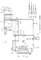
図1には、本発明の一実施形態に係るヒートポンプ式車両用空調システムの冷媒回路図が示されている。
本実施形態に係るヒートポンプ式車両用空調システム1は、HVACユニット(Heating Ventilation and Air Conditioning Unit)2と、冷暖房が可能なヒートポンプサイクル3とを備えている。
An embodiment according to the present invention will be described below with reference to FIGS.
FIG. 1 is a refrigerant circuit diagram of a heat pump type vehicle air conditioning system according to an embodiment of the present invention.
The heat pump type vehicle
HVACユニット2は、内外気切替えダンパ4により車室内からの内気または外気を切替え導入し、下流側に圧送するブロア5と、ブロア5に連なる空気流路6中に上流側から下流側にかけて順次配設されている車室内蒸発器7および車室内凝縮器8を備えている。このHVACユニット2は、車室側のインストルメントパネル内に設置され、車室内蒸発器7および車室内凝縮器8を介して温調された空気を、車室内に向けて開口されている複数のデフ吹出し口9、フェイス吹出し口10、フット吹出し口11のいずれかから、吹出しモード切替えダンパ12,13,14により選択的に切替えられる吹出しモードに従って車室内に吹出し、車室内を設定温度に空調するものである。
The
冷暖房可能なヒートポンプサイクル3は、冷媒を圧縮する電動圧縮機15と、冷媒の流れ方向を切替える冷媒切替え手段(三方切替え弁)16と、車室外凝縮器17と、レシーバ18と、開閉弁機能付き第1減圧手段(電磁弁付き温度式自動膨張弁)19と、車室内蒸発器7と、逆止弁20と、アキュームレータ21とを順次冷媒配管22により接続して構成される閉サイクルの冷房用冷凍サイクル(冷媒回路)23を備えている(図2参照)。この冷房用冷凍サイクル23は、エンジン駆動方式の車両に適用されている現行の車両用空調装置と略同等のものである。車室外凝縮器17には、外気を通風する車室外ファン24が付設されている。なお、冷媒切替え手段(三方切替え弁)16は、2個の電磁弁を組み合わせた構成により代替してもよい。
The
冷暖房用のヒートポンプサイクル3には、上記冷房用冷凍サイクル23に対して、電動圧縮機15からの吐出配管(吐出回路)22Aに冷媒切替え手段(三方切替え弁)16を介してHVACユニット2内に設けられている車室内凝縮器8が接続され、その冷媒出口が車室外凝縮器17の出口側液冷媒配管22Bに接続されている。また、車室外凝縮器17の出口側液冷媒配管22Bには、第2開閉弁(電磁弁)25および第2減圧手段(膨張弁)26(以下、両者を総称して開閉弁機能付き第2減圧手段26とも云う。)を介して車室外蒸発器27が接続され、その冷媒出口が逆止弁28を介してアキュームレータ21に接続されている。
In the
更に、上記冷房用冷凍サイクル23に対して、開閉弁機能付き第2減圧手段26(第2開閉弁(電磁弁)25および第2減圧手段(膨張弁)26)および車室外蒸発器27をバイパスするように、車室外凝縮器17の出口側液冷媒配管22Bとアキュームレータ21との間に、第3開閉弁(電磁弁)29および第3減圧手段(膨張弁)30(以下、両者を総称して開閉弁機能付き第3減圧手段30とも云う。)と、逆止弁31とを備えたバイパス回路32が接続された構成とされている。
Further, with respect to the cooling
これにより、電動圧縮機15と、冷媒切替え手段(三方切替え弁)16と、車室内凝縮器8と、液冷媒配管22Bと、開閉弁機能付き第2減圧手段26(第2開閉弁25および第2減圧手段26)と、車室外蒸発器27と、逆止弁28と、アキュームレータ21とがこの順に冷媒配管22を介して接続される閉サイクルの暖房用ヒートポンプサイクル(冷媒回路)33が構成可能とされている(図3参照)。
Thereby, the
また、この暖房用ヒートポンプサイクル33による暖房運転時、車室外蒸発器27に対し着霜が検知されたとき、開閉弁機能付き第2減圧手段26の第2開閉弁25を閉、開閉弁機能付き第3減圧手段30の第3開閉弁29を開とし、車室内凝縮器8で凝縮された液冷媒をバイパス回路32、開閉弁機能付き第3減圧手段30、逆止弁31を経てアキュームレータ21に導入し、電動圧縮機15に吸込ませるホットガスサイクル33Aによる暖房運転に切替え可能とされている(図4参照)。
Further, during the heating operation by the heating
同様に、電動圧縮機15から吐出されたホットガスを、冷媒切替え手段16を介して車室外凝縮器17、レシーバ18、液冷媒配管22B、バイパス回路32、バイパス回路32中の開閉弁機能付き第3減圧手段30(第3開閉弁29および第3減圧手段30)と逆止弁31、アキュームレータ21を経由して循環させ、車室外凝縮器17を除霜する第1除霜回路34(図5参照)と、電動圧縮機15から吐出されたホットガスを、冷媒切替え手段16を介して車室外凝縮器17、レシーバ18、液冷媒配管22B、開閉弁機能付き第2減圧手段26(第2開閉弁25および第2減圧手段26)、車室外蒸発器27、逆止弁28、アキュームレータ21を経由して循環させ、車室外蒸発器27を除霜する第2除霜回路35(図6参照)と、が構成可能とされている。
Similarly, the hot gas discharged from the
さらに、冷媒回路を暖房用ヒートポンプサイクル(冷媒回路)33とし、同時に車室内蒸発器7の入口側に設けられている開閉弁機能付き第1減圧手段(電磁弁付き温度式自動膨張弁)19の開閉弁機能を開として、車室外蒸発器27と車室内蒸発器7の双方または第2開閉弁25を閉として車室内蒸発器7に冷媒を流すことにより、除湿モードでの運転が選択可能とされている(図7参照)。
Furthermore, the refrigerant circuit is a heating heat pump cycle (refrigerant circuit) 33, and at the same time, the first decompression means (temperature-type automatic expansion valve with electromagnetic valve) 19 with an on-off valve function provided on the inlet side of the vehicle
また、上記ヒートポンプサイクル3において、暖房用ヒートポンプサイクル33を構成する車室外蒸発器27は、冷房用冷凍サイクル23を構成する車室外凝縮器17に対して外気を通風する車室外ファン24の通風路中の下流側に、車室外凝縮器17と互いに平行に設置されることにより、車室外ファン24を共用化している。更に、本実施形態においては、車室外凝縮器17の上部に、車両駆動用のエンジン、モータ、インバータおよびバッテリー等の発熱体を冷却する熱媒体(冷却水等)の熱を放熱するラジエータ36を設置し、その放熱を車室外蒸発器27で吸熱可能な構成としている。なお、このラジエータ36は、車室外凝縮器17と車室外蒸発器27との間に配設してもよい。
In the
次に、上記ヒートポンプ式車両用空調システム1の運転時の冷媒流れを、図2ないし図7を用いて説明する。なお、各図において、運転時の冷媒流れが太線で表示されている。
[冷房運転]
冷房運転時、電動圧縮機15で圧縮された冷媒は、図2に示されるように、吐出配管22Aから冷媒切替え手段16を介して車室外凝縮器17に循環され、車室外ファン24により通風される外気と熱交換されて凝縮される。この液冷媒は、レシーバ18内に貯留された後、液冷媒配管22B、開閉弁機能付き第1減圧手段19を経て減圧され、HVACユニット2内の車室内蒸発器7に供給される。
Next, the refrigerant flow during operation of the heat pump vehicle
[Cooling operation]
During the cooling operation, the refrigerant compressed by the
車室内蒸発器7に供給された冷媒は、ここでブロア5から送風されてくる内気または外気と熱交換されて蒸発され、逆止弁20、アキュームレータ21を経て電動圧縮機15に吸入されることにより再圧縮される。以下、同様のサイクルを繰り返す。この冷房用サイクル23は、エンジン駆動方式の車両に用いられている現行システムの冷房用サイクルを略そのまま共用化することができる。車室内蒸発器7で冷媒との熱交換されることにより冷却された内気または外気は、吹出しモード切替えダンパ12ないし14により切替えられる吹出しモードに応じて、デフ吹出し口9、フェイス吹出し口10、フット吹出し口11のいずれかから車室内に吹出され、車室内の冷房に供されることになる。
The refrigerant supplied to the vehicle
なお、この冷房運転時、開閉弁機能付き第2減圧手段26および開閉弁機能付き第3減圧手段30の第2開閉弁(電磁弁)25および第3開閉弁(電磁弁)29は、いずれも閉とされている。 During this cooling operation, the second on-off valve (solenoid valve) 25 and the third on-off valve (solenoid valve) 29 of the second decompression means 26 with on-off valve function and the third decompression means 30 with on-off valve function are both It is closed.
[暖房運転]
暖房運転時、車室外蒸発器27に着霜する迄の間は、図3に示されるように、電動圧縮機15で圧縮された冷媒は、吐出配管22Aから冷媒切替え手段16を介して車室内凝縮器8に導入され、ここで、ブロア5から送風されてくる内気または外気と熱交換されて放熱される。これによって加熱された空気は、吹出しモードに応じて、デフ吹出し口9、フェイス吹出し口10およびフット吹出し口11のいずれかから車内に吹出され、車室内の暖房に供されることになる。なお、通常の暖房運転は、窓の曇りを防止するため、外気導入モードで行われる。
[Heating operation]
During the heating operation, until the
車室内凝縮器8で放熱され、凝縮液化された冷媒は、液冷媒配管22B、開閉弁機能付き第2減圧手段26(この場合、第2開閉弁(電磁弁)25は開)を経て減圧され、車室外蒸発器27に供給される。この気液二相冷媒は、車室外蒸発器27で車室外ファン24により通風される外気と熱交換され、外気から吸熱して蒸発された後、逆止弁28、アキュームレータ21を経て電動圧縮機15に吸入され、再圧縮される。以下、同様のサイクルが繰り返される。この暖房用ヒートポンプサイクル33によってヒートポンプ暖房が行なわれることになる。
The refrigerant radiated from the
このように、既存の冷房用サイクル23を利用し、その吐出配管(吐出回路)22Aに対して冷媒切替え手段16を介して暖房用の車室内凝縮器8を接続するとともに、開閉弁機能付き第2減圧手段26(第2開閉弁(電磁弁)25と第2減圧手段(膨張弁)26)を介して暖房用の車室外蒸発器27を接続することによって、一部の回路部分および機器類を共用化して暖房用のヒートポンプサイクル33を構成することができる。
なお、この暖房運転時、開閉弁機能付き第1減圧手段19の電磁弁および開閉弁機能付き第3減圧手段30の第2開閉弁(電磁弁)29は、いずれも閉とされている。
In this way, the existing
During the heating operation, the electromagnetic valve of the first pressure reducing means 19 with the on-off valve function and the second on-off valve (electromagnetic valve) 29 of the third pressure reducing means 30 with the on-off valve function are both closed.
また、暖房運転時、外気温が低いと、車外蒸発器27の表面に着霜し、それが進行すると暖房能力が低下する。そこで、車室外蒸発器27に着霜が検知されたとき、暖房運転を継続する場合、図4に示されるように、開閉弁機能付き第2減圧手段の第2開閉弁(電磁弁)25を閉、開閉弁機能付き第3減圧手段30の第3開閉弁29を開とし、電動圧縮機15からのホットガス冷媒を冷媒切替え手段16により車室内凝縮器8に導入し、そこで放熱させて暖房に供した後、その液冷媒をバイパス回路32、第3減圧手段30、逆止弁31を経てアキュームレータ21に導き、電動圧縮機15へと吸入させるホットガスサイクル33Aに切替えることにより、暖房運転を継続できるようにしている。
In addition, if the outside air temperature is low during heating operation, frost forms on the surface of the outside-
[除湿運転]
上記の暖房用ヒートポンプサイクル33を維持したまま、図7に示されるように、開閉弁機能付き第1減圧手段(電磁弁付き温度式自動膨張弁)19の電磁弁を開として液冷媒の一部を車室内蒸発器7に導入し、ブロア5から送風されてくる空気を車室内蒸発器7で冷却除湿した後、下流側の車室内凝縮器8で加熱して車室内に吹出すことにより、除湿運転を行うことができる。この場合、車室内蒸発器7および車室外蒸発器27の双方で蒸発した冷媒は、アキュームレータ21で合流された後、電動圧縮機15に吸入され、再圧縮されることになる。なお、この除湿運転は、開閉弁機能付き第2減圧手段の第2開閉弁25を閉とし、車室内蒸発器7のみに冷媒を流すことによっても行わせることができる。
[Dehumidifying operation]
While maintaining the heating
さらに、上記の除湿運転時に、開閉弁機能付き第1減圧手段(電磁弁付き温度式自動膨張弁)19の開閉弁機能を利用して、その開閉弁(電磁弁)を適宜開閉制御することにより車室内蒸発器7での冷却量を制御し、車室内凝縮器8で加熱されて車室内に吹出される空気の温度を制御するようにしてもよく、これによっても、温度リニアリティ特性(設定温度に対する追従性)を確保することが可能となる。
Furthermore, by using the opening / closing valve function of the first pressure reducing means (temperature-type automatic expansion valve with electromagnetic valve) 19 with the opening / closing valve function during the above dehumidifying operation, the opening / closing valve (electromagnetic valve) is appropriately controlled to open / close. The amount of cooling in the vehicle
[除霜運転]
上記のように、車室外蒸発器27を機能させ、暖房運転しているときに、車室外蒸発器27に対して着霜が検知された場合でも、直ちに除霜運転は行わず、車室内凝縮器8を利用したホットガスサイクルに切替えることにより、そのまま暖房運転を継続することができる。このため、車両が走行(使用)されている間は、強制的な除霜は行わず、外気で自然にデフロストされるのを待つことになる。しかし、外気温の低い状態が続くと、除霜されずに車室外蒸発器27に霜が付着したままとなったり、車室外凝縮器17に走行中の着雪や跳ね上がった水分の氷結等が付着したままとなったりすることが想定される。
[Defrosting operation]
As described above, when the outside-
そこで、車両が停止(駐車)とされ、乗員がいなくなった状態で、望ましくは車両バッテリーの充電時または充電後でバッテリー容量に余裕がある時に、空調システム1を運転して除霜を行うようにしている。この除霜運転は、車室外凝縮器17および車室外蒸発器27を順次除霜するため、図4および図5に示されるように、除霜運転1および除霜運転2の2段階で行うとともに、車室外ファン24を停止した状態で行う構成とされている。
Therefore, when the vehicle is stopped (parked) and no occupants are present, preferably when the vehicle battery has sufficient capacity after charging or after charging, the
[除霜運転1]
除霜運転1は、車室外凝縮器17の除霜を行うものであり、図5に示されるように、第1除霜回路34により行われる。この場合、電動圧縮機15からのホットガス冷媒は、冷媒切替え手段16により車室外凝縮器17に導入され、ここで放熱して車室外凝縮器17に付着している雪や氷結等を溶かし、車室外凝縮器17を除霜(デフロスト)する。車室外凝縮器17の除霜作用に供されて凝縮液化された冷媒は、レシーバ18、液冷媒配管22B、バイパス回路32、開閉弁機能付き第3減圧手段30および逆止弁31を経てアキュームレータ21に至り、電動圧縮機15へと吸入される第1除霜回路34を循環することになる。
[Defrosting operation 1]
The
この場合、開閉弁機能付き第1減圧手段19の電磁弁および開閉弁機能付き第2減圧手段26の第2開閉弁(電磁弁)25は、閉とされている。
これによって、ホットガス冷媒を車室外凝縮器17に直接導入して除霜することが可能となる。図5(B)には、この際の第1除霜回路34のモリエル線図が冷凍サイクルのモリエル線図と対比して図示されている。
In this case, the electromagnetic valve of the first pressure reducing means 19 with the on-off valve function and the second on-off valve (solenoid valve) 25 of the second pressure reducing means 26 with the on-off valve function are closed.
As a result, the hot gas refrigerant can be directly introduced into the
[除霜運転2]
車室外凝縮器17の除霜が終了後、図6に示されるように、開閉弁機能付き第2減圧手段26の第2開閉弁25を開、開閉弁機能付き第3減圧手段30の第3開閉弁29を閉として第2除霜回路35を形成し、車室外蒸発器27の除霜運転2が行われる。除霜運転2では、電動圧縮機15からのホットガス冷媒は、冷媒切替え手段16により車室外凝縮器17、レシーバ18、液冷媒配管22B、開閉弁機能付き第2減圧手段26を経て車室外蒸発器27に導入されることになる。
[Defrosting operation 2]
After the defrosting of the
この際、過熱ガスは第2減圧手段26で断熱膨張して車室外蒸発器27に導入され、車室外蒸発器27を加熱することにより表面の霜を溶かす。車室外蒸発器27の除霜に供された冷媒は、逆止弁28、アキュームレータ21を経て電動圧縮機15へと吸入されることにより第2除霜回路35内を循環する。この場合、開閉弁機能付き第1減圧手段19の電磁弁は閉とされていることは云うまでもない。これによって、ホットガス冷媒を車室外蒸発器27に直接導入して除霜することが可能となる。図6(B)には、この際の第2除霜回路35のモリエル線図が冷凍サイクルのモリエル線図と対比して図示されている。
At this time, the superheated gas is adiabatically expanded by the second decompression means 26 and introduced into the vehicle
除霜運転の終了は、第2除霜回路35により車室外蒸発器27の除霜運転を行い、着霜検知手段(後述する車室外蒸発器冷媒温度センサー(T1)48と外気温度センサー(Tamb)45との温度差が所定値a以上か否かで判定)により着霜のないことが確認された時点で終了される構成とされている。つまり、着霜検知手段が作動しないことを以って除霜が完了していることを確認し、除霜残しがないように確実に車室外蒸発器27を除霜できるようにしている。
The end of the defrosting operation is performed by the
以上の運転は、図8に示されている制御装置40により制御されるようになっている。この制御装置40は、車両側の上位制御装置41に接続され、車両側からの情報が入力される構成とされるとともに、コントロールパネル42を備えており、以下のセンサー群からの検出信号と、上位制御装置41およびコントロールパネル42からの入力情報とに基づいて、空調システム1の運転制御を行うものである。
The above operation is controlled by the
制御装置40には、車室内に設置されている車内温度センサー(Tr)43、外気温度センサー(Tamb)44、日射センサー(Ts)45、車速センサー46の他、空調システム1側の車室内蒸発器7に設置されている吹出し空気温度センサー(FS)47、車室外蒸発器27に設置されている車室外蒸発器冷媒温度センサー(T1)48、吐出配管22Aに設置されている高圧センサー(HP)49、車室外凝縮器17の出口側液冷媒配管22Bに設置されている車室外凝縮器冷媒温度センサー(T2)50等からの検出信号が入力されるようになっている。
The
制御装置40は、上記センサー群からの検出信号と、コントロールパネル42および車両側の上位制御装置41からの入力情報に基づき、予め設定されているプログラムに従って所要の演算、処理等を行い、吹出しモード切替えダンパ12ないし14用のアクチエータ51、内外気切替えダンパ4用のアクチエータ52、ブロア5用のモータ53、車室外ファン24用のモータ54、電動圧縮機15用のモータ55、冷媒切替え手段(三方切替え弁)16用の電磁コイル56、開閉弁機能付き第1減圧手段(電磁弁付き温度式自動膨張弁)19の電磁弁および第2開閉弁(電磁弁)25、第3開閉弁(電磁弁)29用の各電磁コイル57、58、59等を制御し、上記の如く空調システム1の運転を制御する機能を担うものである。
Based on the detection signal from the sensor group and the input information from the
以下に、この制御装置40による空調システム1の運転制御を、図9ないし図13に示すフロー図を参照して説明する。
図9は、空調システム1のメイン制御フロー図であり、制御がスタートすると、まずステップS1において、コントロールパネル42の設定を読み込み、更にステップS2において、各種センサー群43ないし50からの検出値を読み込む。これらの設定値および検出値に基づいて、ステップS3では、目標吹出し温度Ttarを算出し、ステップS4に移行する。ここでは、除湿運転ありか否かが判定され、YESであれば、ステップS5に移行して「冷房/除湿運転制御」に入り、NOであれば、ステップS6に移行して「暖房運転制御」に入り、その後、ステップS7において、各種センサーの検出値を出力し、スタート点に戻る。
Below, the operation control of the
FIG. 9 is a main control flow diagram of the
ステップS5において、「冷房/除湿運転制御」に入り、冷房運転が選択されると、図10に示される冷房運転制御が実行される。この冷房運転制御では、まずステップS10において、冷媒切替え手段(三方切替え弁)16の流路が決定され、電動圧縮機15からの吐出冷媒を車室外凝縮器17側に循環する回路に切替えられる。引き続き、ステップS11において、開閉弁(電磁弁)の開閉が決定され、開閉弁機能付き第1減圧手段19の電磁弁が開、開閉弁機能付き第2減圧手段26の第2開閉弁25および開閉弁機能付き第3減圧手段30の第3開閉弁29が閉とされる。これによって、図2に示す冷房用サイクル23が設定される。
In step S5, when “cooling / dehumidification operation control” is entered and the cooling operation is selected, the cooling operation control shown in FIG. 10 is executed. In this cooling operation control, first, in step S10, the flow path of the refrigerant switching means (three-way switching valve) 16 is determined, and the circuit is switched to a circuit that circulates the refrigerant discharged from the
さらに、ステップS12で電動圧縮機15の回転数、ステップS13で内外気切替えダンパ4の切替えによる吸込みモード、ステップS14で吹出しモード切替えダンパ12ないし14の切替えによる吹出しモード、ステップS15でブロア5の駆動電圧、ステップS16で車室外ファン24の駆動電圧等が順次決定され、モータおよびアクチエータ51ないし55が駆動されることによって、車内温度が設定温度となるように冷房運転が実行される。その後、S1(ステップS7)に移行され、冷房運転が継続される。
Further, in step S12, the rotational speed of the
また、ステップS5で除湿運転制御が選択された場合、ステップS10において、冷媒切替え手段(三方切替え弁)16の流路が決定され、電動圧縮機15からの吐出冷媒を車室内凝縮器8に循環させる回路に切替えられる。続いて、ステップS11において、開閉弁(電磁弁)の開閉が決定され、開閉弁機能付き第1減圧手段19の電磁弁および開閉弁機能付き第2減圧手段26の第2開閉弁25が開とされ、開閉弁機能付き第3減圧手段30の第3開閉弁29が閉とされる。これによって、図7に示すように、車室内蒸発器7で冷却・除湿した空気を車室内凝縮器8で加熱して温調する除湿運転が可能となる。
When the dehumidifying operation control is selected in step S5, the flow path of the refrigerant switching means (three-way switching valve) 16 is determined in step S10, and the refrigerant discharged from the
引き続き、ステップS12で電動圧縮機15の回転数、ステップS13で内外気切替えダンパ4の切替えによる吸込みモード、ステップS14で吹出しモード切替えダンパ12ないし14の切替えによる吹出しモード、ステップS15でブロア5の駆動電圧、ステップS16で車室外ファン24の駆動電圧等が順次決定され、モータおよびアクチエータ51ないし55が駆動されることによって、車内温度が設定温度となるように除湿運転が実行される。その後、S1(ステップS7)に移行され、除湿運転が継続される。
Subsequently, the rotational speed of the
なお、この除湿運転は、開閉弁機能付き第1減圧手段19の電磁弁を開、開閉弁機能付き第2減圧手段26の第2開閉弁25および開閉弁機能付き第3減圧手段30の第3開閉弁29を閉とし、車室内蒸発器7のみに冷媒を流して行ってもよく、また、開閉弁機能付き第1減圧手段19の電磁弁を適宜開閉制御し、車室内蒸発器7での冷却量をコントロールしながら行うようにしてもよい。
In this dehumidifying operation, the electromagnetic valve of the first pressure reducing means 19 with the on-off valve function is opened, the second on-off
一方、ステップS6において、「暖房運転制御」に入ると、図11および図12に示される暖房運転制御に移行される。暖房運転制御では、ステップS20において、冷媒切替え手段(三方切替え弁)16の流路が決定され、冷媒を車室内凝縮器8側に流す回路に切替えられる。引き続き、ステップS21において、電磁弁の開閉が決定され、開閉弁機能付き第1減圧手段(電磁弁付き温度式自動膨張弁)19の電磁弁および開閉弁機能付き第3減圧手段30の第3開閉弁29が閉、開閉弁機能付き第2減圧手段26の第2開閉弁25が開とされる。これによって、図3に示す暖房用ヒートポンプサイクル33が設定される。
On the other hand, if “heating operation control” is entered in step S6, the operation proceeds to the heating operation control shown in FIGS. In the heating operation control, in step S20 , the flow path of the refrigerant switching means (three-way switching valve) 16 is determined and switched to a circuit for flowing the refrigerant to the vehicle
その後、ステップS22に移行され、ここで車室外蒸発器27に対する着霜の有無が判定される。この着霜判定S1は、車室外蒸発器冷媒温度センサー48の検出値T1と、外気温度センサー44の検出値Tambとの差が、設定値a以上か否か(T1−Tamb≧a)により判定され、YES(着霜あり)の場合、ステップS23に移行され、NO(着霜なし)の場合、ステップS24に移行される。着霜なしの場合、車室外蒸発器27を蒸発器として機能させ、暖房用ヒートポンプサイクル33により暖房運転が実行される。
Thereafter, the process proceeds to step S22, where it is determined whether frost formation has occurred on the
暖房運転の実行に際し、ステップS24では、内外気切替えダンパ4が外気導入モードと決定され、更にステップS25で電動圧縮機15の回転数、ステップS26で吹出しモード切替えダンパ12ないし14の切替えによる吹出しモード、ステップS27でブロア5の駆動電圧、ステップS28で車室外ファン24の駆動電圧等が順次決定され、モータおよびアクチエータ51−55が駆動されることにより、車内温度が設定温度となるように暖房運転が実行されることになる。その後、S1(=ステップS7)に移行され、暖房運転が継続される。
When executing the heating operation, in step S24, the inside / outside
また、ステップS22で着霜ありと判定され、ステップS23に移行される場合、更に車両電源がON(Key ON)か否かが判定され、NOの場合は、ステップS29(図12参照)に移行され、YESの場合は、ステップS30に移行される。ステップS30では、内外気切替えダンパ4が外気導入モードまたは内気混合モードとされ、更にステップS31に移って電磁弁の開閉が決定される。
If it is determined in step S22 that frost is present and the process proceeds to step S23, it is further determined whether or not the vehicle power supply is ON (Key ON). If NO, the process proceeds to step S29 (see FIG. 12). If YES, the process proceeds to step S30. In step S30, the inside / outside
この場合、ステップS31では、開閉弁機能付き第1減圧手段(電磁弁付き温度式自動膨張弁)19の電磁弁および開閉弁機能付き第2減圧手段26の第2開閉弁25が閉、開閉弁機能付き第3減圧手段30の第3開閉弁29が開とされる。このため、車室内凝縮器8で放熱することにより暖房に供された冷媒は、車室内凝縮器8で凝縮された後、バイパス回路32、第3減圧手段30、逆止弁31を経てアキュームレータ21に導入され、電動圧縮機15に吸入されるホットガスサイクル33Aに切替えられる。このように、車室外蒸発器27に対する着霜が検知されたときは、図4に示すホットガスサイクル33Aにより暖房運転が継続されることになる。
In this case, in step S31, the electromagnetic valve of the first pressure reducing means (temperature-type automatic expansion valve with electromagnetic valve) 19 with the on-off valve function and the second on-off
ステップS31で電磁弁の開閉が決定され、ホットガスサイクル33Aによる暖房運転に切替えられると、ステップS32で電動圧縮機15の回転数、ステップS33で吹出しモード切替えダンパ12ないし14の切替えによる吹出しモード、ステップS34でブロア5の駆動電圧、ステップS35で車室外ファン24の駆動電圧等が順次決定され、モータおよびアクチエータ51ないし55が駆動されることにより、車内温度が設定温度となるように暖房運転が実行される。その後、S1(=ステップS7)に移行され、車外蒸発器27への着霜にもかかわらず、暖房運転が継続されることになる。
When the opening / closing of the solenoid valve is determined in step S31 and the heating operation is switched to the
さらに、ステップS23において、NO、すなわち車両電源がOFFと判定され、ステップS29(図12参照)に移行した場合、ステップS29で車両電源(バッテリー)が充電中または充電完了か否かが判定される。ここで、NOと判定された場合、バッテリーの充電量が充分でないが未充電中である、あるいは未だ乗員が乗っていると判断し、ステップS36に移行して除霜運転の一時停止を処理する。その後、S1(=ステップS7)に移行し、同様の動作を繰り返す。 Further, in step S23, NO, that is, if it is determined that the vehicle power supply is OFF and the process proceeds to step S29 (see FIG. 12), it is determined in step S29 whether the vehicle power supply (battery) is being charged or whether charging is completed. . Here, when it is determined NO, it is determined that the amount of charge of the battery is not sufficient but is not being charged, or that a passenger is still on, and the process proceeds to step S36 to process the suspension of the defrosting operation. . Thereafter, the process proceeds to S1 (= step S7) and the same operation is repeated.
一方、ステップS29でYESと判定されると、車両が停車中(駐車中)で乗員が乗っておらず、かつ車両電源(バッテリー)が充電中もしくは充電完了していると判断し、ステップS37に移行して車室外凝縮17を除霜する「除霜運転制御1」が実行される。車室外凝縮器17および車室外蒸発器27の霜は、着霜後の運転中に自然にデフロストされている可能性もあるが、着霜判定された後の車両電源OFF時には、必ず「除霜運転制御1,2」が実行されるようになっている。
On the other hand, if “YES” is determined in step S29, it is determined that the vehicle is stopped (parked) and no occupant is on the vehicle, and the vehicle power source (battery) is being charged or has been fully charged. The “
除霜運転制御1では、図13に示されるように、ステップS50において、冷媒切替え手段(三方切替え弁)16の流路が決定され、電動圧縮機15からのホットガス冷媒を車室外凝縮器17側に流す回路に切替えられる。引き続き、ステップS51において、電磁弁の開閉が決定され、開閉弁機能付き第3減圧手段30の第3開閉弁29が開、開閉弁機能付き第1減圧手段19の電磁弁および開閉弁機能付き第2減圧手段26の第2開閉弁25が閉とされる。これによって、図5に示す如く第1除霜回路34が設定される。
In the
その後、ステップS52に移行され、ステップS52で電動圧縮機15の回転数、ステップS53で内外気切替えダンパ4の切替えによる吸込みモード(内気循環モード)、ステップS54で吹出しモード切替えダンパ12ないし14の切替えによる吹出しモード、ステップS55でブロア5の駆動電圧、ステップS56で車室外ファン24の駆動電圧が順次決定され、モータおよびアクチエータ51ないし55が駆動される。これによって、第1除霜回路34を冷媒が循環し、車室外凝縮器17にホットガスが導入され、車室外凝縮器17の除霜運転が実行されることになる。なお、この除霜運転時、車室外ファン24は停止されるようになっている。
Thereafter, the process proceeds to step S52. In step S52, the rotation speed of the
車室外凝縮器17が「除霜運転制御1」により除霜されている間、ステップS38で着霜判定S2が実行される。この着霜判定S2は、車室外凝縮器冷媒温度センサー(T2)50の検出値T2が設定値bを超えているか否か(T2≦b)で除霜が完了したか否かを判断するものである。つまり、検出値T2が設定値b以下の場合、未だ霜が溶けずに残っていると判断(YES)して除霜運転を継続し、検出値T2が設定値bを超えると、霜が溶けて除霜が完了したと判断し、次のステップS39に移行する構成とされている。
While the
ステップS39においては、車室外蒸発器27を除霜するため、「除霜運転制御2」が実行される。「除霜運転制御2」では、図13に示されるように、冷媒切替え手段(三方切替え弁)16の流路決定、電磁弁の開閉決定(この場合は、開閉弁機能付き第2減圧手段26の第2開閉弁25が開、開閉弁機能付き第1減圧手段19の電磁弁および開閉弁機能付き第3減圧手段30の第3開閉弁29が閉とされる。)、電動圧縮機15の回転数、内外気切替えダンパ4の切替えによる吸込みモード(内気循環モード)、吹出しモード切替えダンパ12ないし14の切替えによる吹出しモード、ブロア5の駆動電圧、車室外ファン24の駆動電圧等が順次決定されることにより、モータおよびアクチエータ51ないし55が駆動される。
In step S39, "defrosting
これによって、図6に示されるように、第2除霜回路35に冷媒が循環され、車室外蒸発器27にホットガス冷媒が導入されることにより、車室外蒸発器27の除霜運転が実行される。車室外蒸発器27が「除霜運転制御2」により除霜されている間、ステップS40で着霜判定される。この着霜判定S3は、車室外蒸発器冷媒温度センサー(T1)48の検出値T1が設定値cを超えているか否か(T1≦c)で除霜が完了したか否かを判断するものである。つまり、検出値T1が設定値c以下の場合、未だ霜が溶けずに残っていると判断(YES)して除霜運転を継続し、検出値T1が設定値cを超えると、霜が溶けて除霜が完了したと判断して次のステップS41に移行し、除霜運転が終了される構成とされている。また、この除霜運転時にも、車室外ファン24は停止状態とされるようになっている。
As a result, as shown in FIG. 6, the refrigerant is circulated through the
なお、「除霜運転制御1」および「除霜運転制御2」においては、図13に示されるように、ステップS50ないしステップS56の「除霜運転制御」が終了する度に、S2およびS3(=ステップS38およびステップS40)において、着霜判定を実行する構成とされており、「除霜運転制御1」および「除霜運転制御2」により、車室外凝縮器17および車室外蒸発器27の除霜がすべて終了すると、ステップS41に移行して除霜運転が終了されるようになっている。
In “defrosting
斯くして、本実施形態によると、以下の作用効果が奏される。
本実施形態のヒートポンプ式車両用空調システム1では、従来から知られている電動圧縮機15、車室外凝縮器17、レシーバ18、開閉弁機能付き第1減圧手段19、車室内蒸発器7およびアキュームレータ21からなる冷房用冷凍サイクルに対して、冷媒切替え手段16を介してHVACユニット2内の車室内蒸発器7の下流に設置される車室内凝縮器8を接続するとともに、車室外凝縮器17の出口側液冷媒配管22Bに開閉弁機能付き第2減圧手段26を介して車室外に設置される車室外蒸発器27を接続し、更に車室外凝縮器17の出口側液冷媒配管22Bとアキュームレータ21間に開閉弁機能付き第3減圧手段30を有するバイパス回路32を接続した構成とされている。
Thus, according to the present embodiment, the following operational effects are achieved.
In the heat pump type vehicle
これにより、電動圧縮機15、冷媒切替え手段16、車室内凝縮器8、液冷媒配管22B、開閉弁機能付き第2減圧手段26、車室外蒸発器27、アキュームレータ21を介して暖房用ヒートポンプサイクル33を構成することができ、同様に、暖房運転時、車室外蒸発器27に着霜したとき、電動圧縮機15からのホットガス冷媒を冷媒切替え手段16により車室外凝縮器17、液冷媒配管22B、開閉弁機能付き第3減圧手段30を有するバイパス回路32、アキュームレータ21を経て循環させ、車室外凝縮器17の雪、氷結等を除霜する第1除霜回路34と、電動圧縮機15からのホットガス冷媒を冷媒切替え手段16で車室外凝縮器17、液冷媒配管22B、開閉弁機能付き第2減圧手段26、車室外蒸発器27およびアキュームレータ21を経て循環させ、車室外蒸発器27の霜を除霜する第2除霜回路35との2つの除霜回路を構成することができる。
Thus, the
このため、低外気温下の暖房運転時により、車室外蒸発器27の着霜し、あるいは車室外凝縮器17に雪、氷結等が付着したとしても、車両が停車中(駐車中)で乗員が乗っておらず、かつ車両電源(バッテリー)が充電中もしくは充電完了しているときに、第1除霜回路34および第2除霜回路35を介して車室外凝縮器17および車室外蒸発器27に電動圧縮機15から吐出されたホットガス冷媒を導入し、それぞれデフロストすることができ、低外気温下であっても短時間に効率よくデフロストすることが可能となる。
For this reason, even if the
しかも、エンジン駆動方式の車両に適用されている現行の車両用空調システムの冷房用冷媒回路や構成機器類を殆んどそのまま共用化できるため、最小限の暖房用回路および機器を追加することにより、構成が比較的簡素で低コストでかつ搭載性に優れ、EV車やHEV,PHEV車等に対して好適に適用できる信頼性の高い高効率のヒートポンプ式車両用空調システム1を提供することができる。
Moreover, since the cooling refrigerant circuit and components of the current vehicle air-conditioning system applied to engine-driven vehicles can be shared almost as they are, by adding a minimum heating circuit and equipment To provide a highly-reliable and highly efficient heat pump vehicle
さらに、低外気温下での暖房運転により、車室外蒸発器27に着霜したとしても、車室内凝縮器8に電動圧縮機15からのホットガス冷媒を流し、そこで放熱して液化された冷媒をバイパス回路32、第3減圧手段30、逆止弁31、アキュームレータ21を経て電動圧縮機15に吸入させるホットガスサイクル33Aにより暖房するホットガス暖房に切替え可能とされているため、そのまま暖房運転を継続することができる。従って、暖房運転中に除霜運転に切替えられることによる暖房運転の中断や消費電力のロスを解消するとともに、暖房運転の中断による窓曇りの発生等を回避し、暖房効果や安全性を確保することができる。
Furthermore, even if the
また、除霜運転は、車両を停止した後、乗員がいない状態で、かつ車両バッテリーの充電中もしくは充電後に行うようにしているため、除霜運転が車両の走行距離に影響を及ぼすことを回避することができるとともに、車両バッテリーの充電時もしくは充電後のバッテリー容量に余裕がある時に除霜運転を行うことができる。従って、乗員に何ら影響を及ぼさない状態で効率よく確実に車室外凝縮器17および車室外蒸発器27を除霜することができる。
In addition, the defrosting operation is performed after the vehicle is stopped, with no occupants, and while the vehicle battery is being charged or after being charged, thus preventing the defrosting operation from affecting the travel distance of the vehicle. The defrosting operation can be performed when the vehicle battery is charged or when the battery capacity after charging is sufficient. Therefore, the
また、本実施形態においては、車室外凝縮器17の出口側液冷媒配管22Bにレシーバ18を設けるとともに、車室内蒸発器7の入口側に設けられる開閉弁機能付き第1減圧手段19を電磁弁付き温度式自動膨張弁としているため、レシーバとの組み合わせで温度式自動膨張弁の使用を可能とし、車室内蒸発器7の蒸発性能を安定化することにより、その制御性および信頼性を確保し、冷房性能を高めることができるとともに、電磁弁付き温度式自動膨張弁を設置するHVACユニット2周りの構成およびその制御系の簡素化を図ることができる。
Further, in the present embodiment, the
また、本実施形態では、暖房用ヒートポンプサイクル33に冷媒を循環させた状態で、車室内蒸発器7の入口側の開閉弁機能付き第1減圧手段19の開閉弁機能を開とし、車室内蒸発器7および車室外蒸発器27の双方もしくは開閉弁機能付き第2減圧手段26を閉として車室内蒸発器7のみに冷媒を流すことにより、除湿モードが選択可能とされているため、冷房または暖房運転時に、必要に応じて除湿モードを選択し、車室内凝縮器8を放熱器、車室外蒸発器27および車室内蒸発器7の双方もしくは車室内蒸発器7のみを蒸発器として機能させる除湿運転に切替え、温調制御を行わせることができる。
In the present embodiment, in the state in which the refrigerant is circulated through the heating
これにより、冷房または暖房運転時、適宜除湿モードに切替えて温調制御を行わせ、快適な除湿運転を実行することができる。なお、この除湿運転時、車室内蒸発器7および車室外蒸発器27の双方を使用することにより、温度リニアリティ特性(設定温度に対する追従性)を向上することができる。
Thereby, at the time of cooling or heating operation, it is possible to appropriately switch to the dehumidifying mode to perform temperature control, and to perform a comfortable dehumidifying operation. In this dehumidifying operation, the temperature linearity characteristic (trackability with respect to the set temperature) can be improved by using both the vehicle
さらに、本実施形態では、車室外蒸発器27を、車室外凝縮器17用の車室外ファン24の通風路中において、車室外凝縮器17の下流側に配設するとともに、第1除霜回路34および第2除霜回路35を用いた除霜運転時、車室外ファン24を停止状態とするようにしているため、車室外ファン24を車室外凝縮器17および車室外蒸発器27用に共用化し、システム構成の簡素化、低コスト化を図ることができる。また、車室外凝縮器17および車室外蒸発器27をホットガス冷媒で内部から加熱して除霜する方式としていることから、第1除霜回路34および第2除霜回路35による除霜運転時、車室外ファン24を止めて除霜でき、除霜運転のための消費電力を低減することができる。
Furthermore, in the present embodiment, the outside-
また、除霜運転時、第1除霜回路34により車室外凝縮器17側に付着している雪や跳ね上がった水分の氷結等をホットガス冷媒で除霜した後、第2除霜回路35に切替え、車室外蒸発器27の着霜をホットガス冷媒で除霜するようにしているため、車室外凝縮器17および車室外蒸発器27をそれぞれ個別にホットガス冷媒を集中的に投入して順次除霜することができる。従って、低外気温下であっても、車室外凝縮器17および車室外蒸発器27を短時間に効率的にデフロストすることができる。
Further, during the defrosting operation, the
なお、本発明は、上記実施形態にかかる発明に限定されるものではなく、その要旨を逸脱しない範囲において、適宜変形が可能である。例えば、上記実施形態では、ヒートポンプ暖房運転時に、車室外蒸発器27に着霜しても、車両走行中に除霜運転しないようにしているが、車両走行中に霜が自然にデフロストされた場合、車室外蒸発器27を用いたヒートポンプ暖房運転を復帰させるようにしてもよい。また、上記実施形態では、車室内蒸発器7の入口側の開閉弁機能付き第1減圧手段19を、車室内蒸発器7の性能を安定的に確保できる制御性のよい温度式自動膨張弁とし、その制御性を確保するため、車室外凝縮器17の出口にレシーバ18を設けた構成としているが、温度式自動膨張弁以外の減圧手段を用いる場合、レシーバ18は省略してもよい。
In addition, this invention is not limited to the invention concerning the said embodiment, In the range which does not deviate from the summary, it can change suitably. For example, in the above embodiment, during the heat pump heating operation, even if the outside-
さらに、上記実施形態では、開閉弁機能付き第1減圧手段19を、電磁弁付き温度式自動膨張弁としているが、個別に電磁弁と温度式自動膨張弁を直列に接続した構成としてもよい。また、開閉弁機能付き第2減圧手段26および開閉弁機能付き第3減圧手段30について、それぞれ第2減圧手段(膨張弁)26および第3減圧手段(膨張弁)30の入口側に、第2開閉弁(電磁弁)25および第3開閉弁(電磁弁)29を設けたものとしているが、これらを開閉弁機能備えた電子膨張弁で代替してもよく、本発明はこれらの形態を包含するものであることは云うまでもない。 Furthermore, in the said embodiment, although the 1st pressure reduction means 19 with an on-off valve function is made into the temperature type automatic expansion valve with a solenoid valve, it is good also as a structure which connected the solenoid valve and the temperature type automatic expansion valve in series separately. In addition, the second decompression means 26 with the on-off valve function and the third decompression means 30 with the on-off valve function are respectively connected to the inlet side of the second decompression means (expansion valve) 26 and the third decompression means (expansion valve) 30. Although the on-off valve (solenoid valve) 25 and the third on-off valve (solenoid valve) 29 are provided, these may be replaced by an electronic expansion valve having an on-off valve function, and the present invention includes these forms. It goes without saying that it is what you do.
1 ヒートポンプ式車両用空調システム
2 HVACユニット
7 車室内蒸発器
8 車室内凝縮器
15 電動圧縮機
16 冷媒切替え手段(三方切替え弁)
17 車室外凝縮器
18 レシーバ
19 開閉弁機能付き第1減圧手段(電磁弁付き温度式自動膨張弁)
21 アキュームレータ
22A 吐出配管(吐出回路)
22B 液冷媒配管
23 冷房用冷凍サイクル(冷媒回路)
24 車室外ファン
26 開閉弁機能付き第2減圧手段(開閉弁25および膨張弁26)
30 開閉弁機能付き第3減圧手段(開閉弁29および膨張弁30)
32 バイパス回路
33 暖房用ヒートポンプサイクル(冷媒回路)
33A ホットガスサイクル
34 第1除霜回路
35 第2除霜回路
DESCRIPTION OF
17 Out-of-
21
22B Liquid
24 Outside-
30 Third pressure reducing means with on-off valve function (on-off
32
33A
Claims (7)
前記HVACユニット内の前記車室内蒸発器の下流側に配設され、冷媒入口が前記電動圧縮機の吐出回路に切替え手段を介して接続されるとともに、冷媒出口が前記車室外凝縮器出口側の液冷媒配管に接続された車室内凝縮器と、
冷媒入口が前記車室外凝縮器の出口側液冷媒配管に開閉弁機能付き第2減圧手段を介して接続され、冷媒出口が前記アキュームレータに接続された車室外蒸発器と、
前記車室外凝縮器の出口側液冷媒配管と前記アキュームレータとの間に接続された開閉弁機能付き第3減圧手段を有するバイパス回路と、を備え、
前記切替え手段は、前記電動圧縮機から吐出された冷媒を、前記車室内凝縮器に導くか前記車室外凝縮器に導くかを切替え、
前記電動圧縮機、前記切替え手段、前記車室内凝縮器、前記液冷媒配管、前記開閉弁機能付き第2減圧手段、前記車室外蒸発器、前記アキュームレータにより暖房用のヒートポンプサイクルが構成可能されているとともに、
暖房運転時、前記車室外蒸発器に着霜したとき、前記電動圧縮機からのホットガス冷媒を前記切替え手段により前記車室外凝縮器、前記液冷媒配管、前記開閉弁機能付き第3減圧手段を有するバイパス回路、前記アキュームレータを経て循環させ、前記車室外凝縮器を除霜する第1除霜回路と、前記電動圧縮機からのホットガス冷媒を前記切替え手段によって前記車室外凝縮器、前記液冷媒配管、前記開閉弁機能付き第2減圧手段、前記車室外蒸発器、前記アキュームレータを経て循環させ、前記車室外蒸発器を除霜する第2除霜回路と、が構成可能とされていることを特徴とするヒートポンプ式車両用空調システム。 An electric compressor, a vehicle exterior condenser, a first pressure reducing means with an on-off valve function, a vehicle interior evaporator provided in the HVAC unit, a cooling refrigeration cycle in which an accumulator is connected in this order;
The refrigerant outlet is disposed on the downstream side of the vehicle interior evaporator in the HVAC unit, the refrigerant inlet is connected to the discharge circuit of the electric compressor via a switching means, and the refrigerant outlet is on the outlet side of the condenser outside the vehicle compartment. A vehicle interior condenser connected to the liquid refrigerant pipe;
An outside-vehicle evaporator in which a refrigerant inlet is connected to an outlet-side liquid refrigerant pipe of the outside-condenser through a second pressure reducing means with an on-off valve function, and a refrigerant outlet is connected to the accumulator;
A bypass circuit having a third pressure reducing means with an on-off valve function connected between the outlet side liquid refrigerant pipe of the outdoor condenser and the accumulator;
The switching means switches whether the refrigerant discharged from the electric compressor is guided to the vehicle interior condenser or the vehicle exterior condenser,
A heat pump cycle for heating can be configured by the electric compressor, the switching unit, the vehicle interior condenser, the liquid refrigerant pipe, the second decompression unit with an on-off valve function, the vehicle exterior evaporator, and the accumulator. With
During the heating operation, when the outside evaporator is frosted, hot gas refrigerant from the electric compressor is switched by the switching means to the outside condenser, the liquid refrigerant pipe, and the third pressure reducing means with on-off valve function. A bypass circuit having a first defrosting circuit that circulates through the accumulator and defrosts the vehicle exterior condenser, and a hot gas refrigerant from the electric compressor is switched by the switching means to the vehicle exterior condenser and the liquid refrigerant. A second defrosting circuit configured to circulate through the piping, the second pressure reducing means with the on-off valve function, the outside-vehicle-room evaporator, and the accumulator to defrost the outside-vehicle evaporator. A heat pump type air conditioning system for vehicles.
前記車室外蒸発器に着霜した場合、前記第1除霜回路を介して前記車室外凝縮器側に付着している雪や跳ね上がった水分の氷結等をホットガス冷媒で除霜した後、前記第2除霜回路に切替え、前記車室外蒸発器の着霜をホットガス冷媒で除霜することを特徴とするヒートポンプ式車両用空調システムの除霜方法。 In the defrosting method of the heat pump type vehicle air conditioning system according to any one of claims 1 to 5,
When the outside evaporator is frosted, after defrosting the snow or the icing of the water splashed on the outside condenser through the first defrosting circuit with a hot gas refrigerant, A defrosting method for a heat pump vehicle air conditioning system, wherein the defrosting circuit is switched to a second defrosting circuit, and the frosting of the outdoor evaporator is defrosted with a hot gas refrigerant.
Priority Applications (5)
| Application Number | Priority Date | Filing Date | Title |
|---|---|---|---|
| JP2013145648A JP6257940B2 (en) | 2013-07-11 | 2013-07-11 | Heat pump type vehicle air conditioning system and defrosting method thereof |
| CN201480025814.9A CN105555564B (en) | 2013-07-11 | 2014-04-15 | Heat-pump-type vehicle air-conditioning systems and its Defrost method |
| PCT/JP2014/060734 WO2015004967A1 (en) | 2013-07-11 | 2014-04-15 | Heat-pump-type vehicle air conditioning system and defrosting method thereof |
| DE112014003184.4T DE112014003184T5 (en) | 2013-07-11 | 2014-04-15 | Heat pump vehicle air conditioning and defrosting |
| US14/787,932 US10040336B2 (en) | 2013-07-11 | 2014-04-15 | Heat-pump-type vehicle air conditioning system and defrosting method thereof |
Applications Claiming Priority (1)
| Application Number | Priority Date | Filing Date | Title |
|---|---|---|---|
| JP2013145648A JP6257940B2 (en) | 2013-07-11 | 2013-07-11 | Heat pump type vehicle air conditioning system and defrosting method thereof |
Publications (3)
| Publication Number | Publication Date |
|---|---|
| JP2015016801A JP2015016801A (en) | 2015-01-29 |
| JP2015016801A5 JP2015016801A5 (en) | 2015-12-17 |
| JP6257940B2 true JP6257940B2 (en) | 2018-01-10 |
Family
ID=52279664
Family Applications (1)
| Application Number | Title | Priority Date | Filing Date |
|---|---|---|---|
| JP2013145648A Expired - Fee Related JP6257940B2 (en) | 2013-07-11 | 2013-07-11 | Heat pump type vehicle air conditioning system and defrosting method thereof |
Country Status (5)
| Country | Link |
|---|---|
| US (1) | US10040336B2 (en) |
| JP (1) | JP6257940B2 (en) |
| CN (1) | CN105555564B (en) |
| DE (1) | DE112014003184T5 (en) |
| WO (1) | WO2015004967A1 (en) |
Families Citing this family (19)
| Publication number | Priority date | Publication date | Assignee | Title |
|---|---|---|---|---|
| JP6015607B2 (en) * | 2013-09-18 | 2016-10-26 | 株式会社デンソー | Air conditioning unit for vehicles |
| JP5884807B2 (en) * | 2013-10-16 | 2016-03-15 | トヨタ自動車株式会社 | Hybrid vehicle |
| JP6553931B2 (en) * | 2015-04-23 | 2019-07-31 | カルソニックカンセイ株式会社 | Vehicle air conditioner |
| JP6465212B2 (en) * | 2015-08-03 | 2019-02-06 | 株式会社デンソー | Refrigeration cycle equipment |
| JP6323489B2 (en) * | 2015-08-04 | 2018-05-16 | 株式会社デンソー | Heat pump system |
| CZ306309B6 (en) * | 2015-09-24 | 2016-11-23 | Jaroslav Kolář | Method of increasing performance factor and output of heat pumps |
| CN108016404B (en) * | 2016-11-04 | 2020-11-06 | 上海汽车集团股份有限公司 | Windshield defogging control method, control device and defogging system |
| CN107160972B (en) * | 2017-06-19 | 2023-05-23 | 珠海格力电器股份有限公司 | Electric automobile, heat pump air conditioner assembly of electric automobile and control method of heat pump air conditioner assembly |
| KR102445224B1 (en) * | 2017-10-27 | 2022-09-20 | 한온시스템 주식회사 | Heat pump system for vehicle and control method |
| CN108215714A (en) * | 2018-01-19 | 2018-06-29 | 上海威乐汽车空调器有限公司 | Electric automobile air conditioner heat pump system and its operation principle |
| JP7056819B2 (en) * | 2018-06-27 | 2022-04-19 | サンデン・オートモーティブクライメイトシステム株式会社 | Vehicle air conditioner |
| JP7099899B2 (en) * | 2018-07-25 | 2022-07-12 | 三菱重工サーマルシステムズ株式会社 | Vehicle air conditioner |
| CN108944353B (en) * | 2018-09-14 | 2024-02-09 | 郑州科林车用空调有限公司 | Integrated electric cold and warm defroster for new energy bus |
| US11681309B2 (en) * | 2019-01-03 | 2023-06-20 | Westinghouse Air Brake Technologies Corporation | Thermal management system and method |
| JP6746742B1 (en) * | 2019-03-15 | 2020-08-26 | 三菱重工サーマルシステムズ株式会社 | Vehicle air conditioning system and method for controlling vehicle air conditioning system |
| DE102020107652A1 (en) | 2020-03-19 | 2021-09-23 | Audi Aktiengesellschaft | Method for defrosting an external heat exchanger, operated as an air heat pump, of a refrigeration system for a motor vehicle, refrigeration system and motor vehicle with such a refrigeration system |
| US11273686B2 (en) * | 2020-03-19 | 2022-03-15 | Ford Global Technologies, Llc | Electrified vehicle with control strategy for managing battery and cabin cooling |
| FR3109432B1 (en) | 2020-04-16 | 2022-12-09 | Psa Automobiles Sa | HEAT TREATMENT AFTER STOPPING A MOTOR VEHICLE WITH ELECTRIC TRACTION |
| CN112172456B (en) * | 2020-10-19 | 2022-12-27 | 重庆邮电大学 | Defrosting control system and method for heat pump air conditioner of electric automobile |
Family Cites Families (11)
| Publication number | Priority date | Publication date | Assignee | Title |
|---|---|---|---|---|
| KR101241222B1 (en) * | 2011-07-21 | 2013-03-13 | 기아자동차주식회사 | Heat pump system control method for vehicle |
| JP2961196B2 (en) * | 1993-06-28 | 1999-10-12 | 三菱自動車工業株式会社 | Vehicle air conditioner |
| JPH07132728A (en) * | 1993-11-05 | 1995-05-23 | Calsonic Corp | Air conditioner for automobile |
| JP4341093B2 (en) * | 1999-01-13 | 2009-10-07 | 株式会社デンソー | Air conditioner |
| JP2000313224A (en) * | 1999-04-28 | 2000-11-14 | Denso Corp | Air conditioner for vehicle |
| JP2003063236A (en) * | 2001-08-27 | 2003-03-05 | Denso Corp | Air conditioner for vehicle |
| JP2011225187A (en) * | 2010-04-23 | 2011-11-10 | Honda Motor Co Ltd | Heat pump type air conditioning system for vehicle |
| JP5611072B2 (en) | 2011-01-28 | 2014-10-22 | 三菱重工業株式会社 | Heat pump air conditioner for vehicle and defrosting method thereof |
| CN102958724B (en) * | 2010-11-01 | 2015-06-24 | 三菱重工业株式会社 | Heat-pump vehicular air conditioner and defrosting method thereof |
| JP5866600B2 (en) * | 2011-11-10 | 2016-02-17 | 株式会社テージーケー | Vehicle air conditioner, composite valve and control valve |
| CN202511534U (en) | 2012-02-29 | 2012-10-31 | 长城汽车股份有限公司 | Heat pump type air conditioning system of electric vehicle |
-
2013
- 2013-07-11 JP JP2013145648A patent/JP6257940B2/en not_active Expired - Fee Related
-
2014
- 2014-04-15 CN CN201480025814.9A patent/CN105555564B/en not_active Expired - Fee Related
- 2014-04-15 DE DE112014003184.4T patent/DE112014003184T5/en not_active Ceased
- 2014-04-15 US US14/787,932 patent/US10040336B2/en not_active Expired - Fee Related
- 2014-04-15 WO PCT/JP2014/060734 patent/WO2015004967A1/en active Application Filing
Also Published As
| Publication number | Publication date |
|---|---|
| JP2015016801A (en) | 2015-01-29 |
| WO2015004967A1 (en) | 2015-01-15 |
| US10040336B2 (en) | 2018-08-07 |
| CN105555564A (en) | 2016-05-04 |
| US20160075212A1 (en) | 2016-03-17 |
| DE112014003184T5 (en) | 2016-03-24 |
| CN105555564B (en) | 2018-06-19 |
Similar Documents
| Publication | Publication Date | Title |
|---|---|---|
| JP6257940B2 (en) | Heat pump type vehicle air conditioning system and defrosting method thereof | |
| US9884536B2 (en) | Heat-pump automotive air conditioner and defrosting method of the heat-pump automotive air conditioner | |
| JP5611072B2 (en) | Heat pump air conditioner for vehicle and defrosting method thereof | |
| EP2752315B1 (en) | Air-conditioning apparatus for vehicles | |
| JP6323489B2 (en) | Heat pump system | |
| JP5676738B2 (en) | Vehicle air conditioning system | |
| EP2679421B1 (en) | Vehicle air conditioning system | |
| JP6391907B2 (en) | Vehicle air conditioner and operation method thereof | |
| JP2011195021A (en) | Heat pump device for vehicle | |
| JP6037773B2 (en) | Heat pump type air conditioner for vehicle and vehicle | |
| CN112424006B (en) | Air conditioner for vehicle | |
| CN113015639A (en) | Air conditioner for vehicle | |
| JP2013075650A (en) | Vehicle temperature control system | |
| WO2020235263A1 (en) | In-vehicle device temperature adjusting device and vehicle air conditioning device provided with same | |
| JP2012162149A (en) | Heat pump type vehicular air conditioner | |
| JP2014034301A (en) | Refrigeration cycle device | |
| JP7164986B2 (en) | Vehicle air conditioner | |
| WO2020100410A1 (en) | Vehicle air-conditioning device | |
| JP2013060145A (en) | Vehicular air conditioner | |
| WO2014185150A1 (en) | Air conditioning device for vehicle, control method for air conditioning device for vehicle, and program | |
| JP5999349B2 (en) | Air conditioner for vehicles | |
| WO2022064944A1 (en) | Air conditioner for vehicle | |
| JP3267147B2 (en) | Vehicle air conditioner | |
| WO2019146326A1 (en) | Vehicle air-conditioning device | |
| WO2020100524A1 (en) | Vehicle air-conditioning device |
Legal Events
| Date | Code | Title | Description |
|---|---|---|---|
| A521 | Request for written amendment filed |
Free format text: JAPANESE INTERMEDIATE CODE: A523 Effective date: 20151028 |
|
| A625 | Written request for application examination (by other person) |
Free format text: JAPANESE INTERMEDIATE CODE: A625 Effective date: 20160708 |
|
| A131 | Notification of reasons for refusal |
Free format text: JAPANESE INTERMEDIATE CODE: A131 Effective date: 20170530 |
|
| A521 | Request for written amendment filed |
Free format text: JAPANESE INTERMEDIATE CODE: A523 Effective date: 20170731 |
|
| TRDD | Decision of grant or rejection written | ||
| A01 | Written decision to grant a patent or to grant a registration (utility model) |
Free format text: JAPANESE INTERMEDIATE CODE: A01 Effective date: 20171107 |
|
| A61 | First payment of annual fees (during grant procedure) |
Free format text: JAPANESE INTERMEDIATE CODE: A61 Effective date: 20171206 |
|
| R150 | Certificate of patent or registration of utility model |
Ref document number: 6257940 Country of ref document: JP Free format text: JAPANESE INTERMEDIATE CODE: R150 |
|
| S111 | Request for change of ownership or part of ownership |
Free format text: JAPANESE INTERMEDIATE CODE: R313111 |
|
| R350 | Written notification of registration of transfer |
Free format text: JAPANESE INTERMEDIATE CODE: R350 |
|
| LAPS | Cancellation because of no payment of annual fees |