JP2012162149A - Heat pump type vehicular air conditioner - Google Patents
Heat pump type vehicular air conditioner Download PDFInfo
- Publication number
- JP2012162149A JP2012162149A JP2011023162A JP2011023162A JP2012162149A JP 2012162149 A JP2012162149 A JP 2012162149A JP 2011023162 A JP2011023162 A JP 2011023162A JP 2011023162 A JP2011023162 A JP 2011023162A JP 2012162149 A JP2012162149 A JP 2012162149A
- Authority
- JP
- Japan
- Prior art keywords
- heating
- evaporator
- outside
- vehicle
- coolant
- Prior art date
- Legal status (The legal status is an assumption and is not a legal conclusion. Google has not performed a legal analysis and makes no representation as to the accuracy of the status listed.)
- Withdrawn
Links
Images


Classifications
-
- B—PERFORMING OPERATIONS; TRANSPORTING
- B60—VEHICLES IN GENERAL
- B60H—ARRANGEMENTS OF HEATING, COOLING, VENTILATING OR OTHER AIR-TREATING DEVICES SPECIALLY ADAPTED FOR PASSENGER OR GOODS SPACES OF VEHICLES
- B60H1/00—Heating, cooling or ventilating [HVAC] devices
- B60H1/00642—Control systems or circuits; Control members or indication devices for heating, cooling or ventilating devices
- B60H1/00814—Control systems or circuits characterised by their output, for controlling particular components of the heating, cooling or ventilating installation
- B60H1/00878—Control systems or circuits characterised by their output, for controlling particular components of the heating, cooling or ventilating installation the components being temperature regulating devices
- B60H1/00899—Controlling the flow of liquid in a heat pump system
- B60H1/00907—Controlling the flow of liquid in a heat pump system where the flow direction of the refrigerant changes and an evaporator becomes condenser
-
- B—PERFORMING OPERATIONS; TRANSPORTING
- B60—VEHICLES IN GENERAL
- B60H—ARRANGEMENTS OF HEATING, COOLING, VENTILATING OR OTHER AIR-TREATING DEVICES SPECIALLY ADAPTED FOR PASSENGER OR GOODS SPACES OF VEHICLES
- B60H1/00—Heating, cooling or ventilating [HVAC] devices
- B60H1/00642—Control systems or circuits; Control members or indication devices for heating, cooling or ventilating devices
- B60H1/00814—Control systems or circuits characterised by their output, for controlling particular components of the heating, cooling or ventilating installation
- B60H1/00878—Control systems or circuits characterised by their output, for controlling particular components of the heating, cooling or ventilating installation the components being temperature regulating devices
- B60H2001/00928—Control systems or circuits characterised by their output, for controlling particular components of the heating, cooling or ventilating installation the components being temperature regulating devices comprising a secondary circuit
-
- B—PERFORMING OPERATIONS; TRANSPORTING
- B60—VEHICLES IN GENERAL
- B60H—ARRANGEMENTS OF HEATING, COOLING, VENTILATING OR OTHER AIR-TREATING DEVICES SPECIALLY ADAPTED FOR PASSENGER OR GOODS SPACES OF VEHICLES
- B60H1/00—Heating, cooling or ventilating [HVAC] devices
- B60H1/00642—Control systems or circuits; Control members or indication devices for heating, cooling or ventilating devices
- B60H1/00814—Control systems or circuits characterised by their output, for controlling particular components of the heating, cooling or ventilating installation
- B60H1/00878—Control systems or circuits characterised by their output, for controlling particular components of the heating, cooling or ventilating installation the components being temperature regulating devices
- B60H2001/00961—Control systems or circuits characterised by their output, for controlling particular components of the heating, cooling or ventilating installation the components being temperature regulating devices comprising means for defrosting outside heat exchangers
Abstract
Description
本発明は、電気自動車やハイブリッド車等の次世代車の空調装置に好適なヒートポンプ式車両用空調装置に関するものである。 The present invention relates to a heat pump vehicle air conditioner suitable for an air conditioner for a next-generation vehicle such as an electric vehicle or a hybrid vehicle.
電気自動車(EV)では、暖房にエンジン排熱を利用することができない。また、ハイブリッド車(HEV,PHEV等)では、省燃費化のために、極力エンジンを停止するように制御されることから、ヒートポンプによる暖房あるいは電気ヒータによる暖房が検討されている。しかし、これらの暖房で消費される電力は非常に大きく、このため、高COP(成績係数)暖房が可能なヒートポンプ方式の方が、電気ヒータ方式(COP≦1)よりも望ましいが、様々な排熱を利用できる高COPヒートポンプ暖房システムを構築しようとすると部品点数の増加やコストアップを招く等の問題があった。 In an electric vehicle (EV), engine exhaust heat cannot be used for heating. In hybrid vehicles (HEV, PHEV, etc.), in order to save fuel, the engine is controlled to be stopped as much as possible. Therefore, heating by a heat pump or heating by an electric heater has been studied. However, the electric power consumed by these heating systems is very large. Therefore, the heat pump system capable of high COP (coefficient of performance) heating is preferable to the electric heater system (COP ≦ 1), but various types of exhaust are required. When trying to construct a high COP heat pump heating system that can use heat, there are problems such as an increase in the number of parts and an increase in cost.
一方、現状は、ガソリン車からEV車やHEV,PHEV車等の次世代車に移行する過渡期にあることから、膨大な開発費を抑制するため、ガソリン車用空調装置を改良して適用する試みがなされている。通常、ガソリン車の場合、HVACユニット内にヒータコアを設け、エンジン冷却用のクーラントを循環させ、エンジンの排熱で暖房するシステムが用いられているが、ヒートポンプ方式では、HVACユニット(Heating Ventilation and Air Conditioning Unit)内に車内凝縮器(サブコンデンサ)を設けるシステムが一般的であり、構成に大きな違いがある。 On the other hand, the current situation is in a transitional period from the transition from gasoline cars to next-generation cars such as EV cars, HEVs, PHEV cars, etc., so in order to suppress enormous development costs, improve and apply air conditioners for gasoline cars Attempts have been made. Usually, in the case of a gasoline vehicle, a system is used in which a heater core is provided in an HVAC unit, coolant for cooling the engine is circulated, and the engine is heated by exhaust heat of the engine. However, in the heat pump system, the HVAC unit (Heating Ventilation and Air) A system in which an in-vehicle condenser (sub-capacitor) is provided in the Conditioning Unit is common, and there is a great difference in configuration.
特に、一般的なヒートポンプシステムの場合、暖房時、冷媒回路を切替えて凝縮器を蒸発器、蒸発器を凝縮器として機能させることになるため、冷媒回路を構成する配管類や蒸発器、凝縮器等の熱交換器を冷房運転および暖房運転の異なる圧力条件下で共用できる構成としなければならず、現行のガソリン車に適用されている車両用空調装置を大幅に変更する必要がある。また、低外気温時、車外側の蒸発器が着霜した場合、如何に除霜するかも大きな課題となる。更に、既存のHVACユニットの流用も検討されているが、ヒータコアを有するHVACユニット内に車内凝縮器(サブコンデンサ)を設けることは、パッケージング上からも温調制御上からも困難である。 In particular, in the case of a general heat pump system, during heating, the refrigerant circuit is switched so that the condenser functions as an evaporator and the evaporator functions as a condenser. Therefore, the piping, evaporator, and condenser that constitute the refrigerant circuit The heat exchanger such as the above must be configured to be shared under different pressure conditions of the cooling operation and the heating operation, and it is necessary to significantly change the vehicle air conditioner applied to the current gasoline vehicle. In addition, when the evaporator on the outside of the vehicle is frosted at a low outside air temperature, how to defrost it becomes a big problem. Furthermore, although diversion of the existing HVAC unit is also being studied, it is difficult to provide an in-vehicle condenser (sub-condenser) in the HVAC unit having a heater core from the viewpoint of packaging and temperature control.
かかる状況下、HVACユニット内に設けられる車内蒸発器に、現行システムの蒸発器を用いながらヒートポンプ暖房を可能とした車両用空調装置の一例として、特許文献1に示されたものが提案されている。これは、現行の冷房用の冷凍サイクルを備えた車両用空調装置のHVACユニットの車内蒸発器下流側に車内凝縮器を設置したものであり、該車内凝縮器を圧縮機の吐出回路に接続し、その出口側に第1電子膨張弁と第1電磁弁を備えたバイパス回路との並列回路を接続するとともに、第2電子膨張弁および車内蒸発器に対して第2電磁弁を備えたバイパス回路を接続した構成とされている。
Under such circumstances, as an example of a vehicle air conditioner that enables heat pump heating while using the evaporator of the current system as an in-vehicle evaporator provided in the HVAC unit, the one shown in
また、特許文献2には、車内蒸発器およびヒータコアを設けたHVACユニットをそのままとし、冷房用サイクルの圧縮機吐出配管に、水/冷媒熱交換器および膨張弁と、開閉弁を備えたバイパス回路との並列回路を設けたものが示されている。これは、水/冷媒熱交換器でエンジンの冷却水を加熱可能とし、暖房時や除湿暖房時、水/冷媒熱交換器側に冷媒を流通させ、ここで冷却水を加熱し、車外凝縮器を蒸発器として機能させて吸熱することにより、暖房性能の向上を図ったものである。
特許文献1に示されるものは、暖房時、車外側の蒸発器が着霜した場合でも、車外側ファンを停止した状態で空調装置を運転し、圧縮機の仕事量に見合った熱量を車内凝縮器および車外蒸発器で放熱することにより、暖房感を得ながら車外蒸発器の除霜を行えるようにしたものである。しかしながら、上記の構成では、車外凝縮器およびそれに接続される冷媒配管系を、凝縮機能と蒸発機能を兼ね備えた熱交換器および高低圧共用の配管系とする必要があり、現行のガソリン車用のシステムの冷媒回路およびHVACユニットを大幅に変更せざるを得ず、車外凝縮器や冷媒配管系を共用化して低コストで簡素な構成のヒートポンプ式車両用空調装置を製造することは困難であった。
また、特許文献2に示されるものでは、暖房モード時、水/冷媒熱交換器で冷却水を加熱し、暖房性能を高めることができる。しかしながら、ヒートポンプ暖房運転時に車外蒸発器に着霜した場合、その機能が中断されてしまう等の問題があるとともに、車外蒸発器の霜をデフロストする方式について、解決策を提示するものではない。また、かかる構成では、最大冷房運転時、吹出し温度の変更指令が出された場合、圧縮機からのホットガスを水/冷媒熱交換器側に切替え、そこで加熱された水をヒータコアに循環させて温調する必要があり、応答遅れによって温調性能の低下が懸念される等の問題があった。
Moreover, in what is shown by
本発明は、このような事情に鑑みてなされたものであって、現行のガソリン車用空調装置の冷房サイクルおよびHVACユニットを共用化し、圧力条件が異なる最小限の暖房用回路および機器を追加するだけで、低コストでかつ搭載性に優れ、しかも車外蒸発器への着霜時の課題をも解消できる、電気自動車やハイブリッド車等に好適なヒートポンプ式車両用空調装置を提供することを目的とする。 The present invention has been made in view of such circumstances, and the cooling cycle and the HVAC unit of the current gasoline vehicle air conditioner are shared, and a minimum heating circuit and equipment having different pressure conditions are added. The purpose of the present invention is to provide a heat pump type vehicle air conditioner suitable for electric vehicles, hybrid vehicles, etc., which is low in cost and excellent in mountability and can also solve the problem of frost formation on the outside evaporator. To do.
上記した課題を解決するために、本発明のヒートポンプ式車両用空調装置は、以下の手段を採用する。
すなわち、本発明にかかるヒートポンプ式車両用空調装置は、車内蒸発器およびヒータコアを備え、前記車内蒸発器および前記ヒータコアにより温調された空気をその下流側に設けられている複数の吹出し口のいずれかから車内に吹出して車室内を空調するHVACユニットと、前記ヒータコアに対して、エンジン、モータおよびインバータ等の車両駆動用機器を冷却するクーラントを循環可能なクーラント循環回路と、電動圧縮機、車外凝縮器、レシーバ、第1膨張弁、前記車内蒸発器がこの順に接続されている冷房用の冷凍サイクルと、前記電動圧縮機の吐出配管に設けられ、ホットガス冷媒と前記クーラント循環回路内を循環する前記クーラントとを熱交換する冷媒/クーラント熱交換器と、前記車外凝縮器の入口側に設けられている切替え手段を介して前記レシーバに接続される第1暖房用回路と、前記レシーバの出口側と前記電動圧縮機の吸入側との間に接続され、第2膨張弁および車外蒸発器が設けられている第2暖房用回路と、を備え、前記電動圧縮機、前記冷媒/クーラント熱交換器、前記切替え手段、前記第1暖房用回路、前記レシーバ、前記第2膨張弁および前記車外蒸発器を備えた前記第2暖房用回路により暖房用のヒートポンプサイクルが構成され、前記冷媒/クーラント熱交換器で加熱された前記クーラントを前記ヒータコアに循環可能とし、前記暖房用ヒートポンプサイクルによる暖房時、前記車外蒸発器に対して着霜が検知されたとき、前記第2暖房用回路側への冷媒流れを遮断して前記車内蒸発器側に冷媒を流通させ、該車内蒸発器を利用した除湿暖房に切替え可能とされていることを特徴とする。
In order to solve the above-described problems, the heat pump type vehicle air conditioner of the present invention employs the following means.
That is, the heat pump type vehicle air conditioner according to the present invention includes an in-vehicle evaporator and a heater core, and any one of a plurality of outlets provided on the downstream side of the temperature-controlled air by the in-vehicle evaporator and the heater core. An HVAC unit that blows air out of the vehicle to air-condition the interior of the vehicle, a coolant circulation circuit that can circulate coolant that cools vehicle drive devices such as the engine, motor, and inverter to the heater core, an electric compressor, Refrigeration cycle for cooling in which a condenser, a receiver, a first expansion valve, and the in-vehicle evaporator are connected in this order, and provided in a discharge pipe of the electric compressor, circulate in the hot gas refrigerant and the coolant circulation circuit A refrigerant / coolant heat exchanger for exchanging heat with the coolant, and an inlet side of the external condenser A first heating circuit connected to the receiver via a switching means, and connected between the outlet side of the receiver and the suction side of the electric compressor, and a second expansion valve and an outside evaporator are provided. A second heating circuit, and the electric compressor, the refrigerant / coolant heat exchanger, the switching means, the first heating circuit, the receiver, the second expansion valve, and the outside evaporator. Further, the second heating circuit constitutes a heat pump cycle for heating, the coolant heated by the refrigerant / coolant heat exchanger can be circulated to the heater core, and the outside evaporation is performed during heating by the heating heat pump cycle. When frost formation is detected with respect to the heater, the refrigerant flow to the second heating circuit side is interrupted and the refrigerant is circulated to the in-vehicle evaporator side. Characterized in that it is capable switched to heating.
本発明によれば、HVACユニットのヒータコアに対して、エンジン、モータおよびインバータ等の車両駆動用機器を冷却するクーラントを循環可能なクーラント循環回路を接続するとともに、車内蒸発器に対して、電動圧縮機、車外凝縮器、レシーバ、第1膨張弁等から構成される冷房用の冷凍サイクルを接続した構成としているため、HVACユニットをガソリン車に適用されている現行の車両用空調装置のHVACユニットと略同一構成とすることができる。さらに、冷房用の冷凍サイクルに対して、冷媒/クーラント熱交換器、第1暖房用回路、第2膨張弁および車外蒸発器を備えた第2暖房用回路を追設し、電動圧縮機、冷媒/クーラント熱交換器、切替え手段、第1暖房用回路、レシーバ、第2膨張弁および車外蒸発器を備えた第2暖房用回路により暖房用のヒートポンプサイクルを構成しているため、原形となる冷房用の冷凍サイクルに冷媒/クーラント熱交換器、第1暖房用回路、第2膨張弁および車外蒸発器を備えた第2暖房用回路等の最小限の暖房用回路と機器を接続することにより、圧力条件が同一となる冷媒回路および機器類を共用化して暖房用のヒートポンプサイクルを構成することができる。従って、冷暖房双方の運転に耐え得る圧力仕様の冷媒回路およびHVACユニットを新たに開発することなく、現行のガソリン車に適用されている車両用空調装置の冷房サイクルと圧力条件が同一となる冷媒回路や機器類を共用化して、圧力条件が異なる最小限の暖房用回路および機器を追加するだけで、構成が比較的簡素で低コストでかつ搭載性に優れ、電気自動車やハイブリッド車等に好適に適用できる信頼性の高い高効率のヒートポンプ式車両用空調装置を提供することができる。また、低外気温時、車外蒸発器に着霜しても、第2暖房用回路への冷媒流れを遮断して車内蒸発器側に冷媒を流し、該車内蒸発器を利用した除湿暖房に切替え可能な構成としているため、車外蒸発器に対する着霜したとしても、そのまま効率のよいヒートポンプ暖房運転を継続することができる。従って、暖房運転中に除霜運転に切替えることによる暖房運転の中断や消費電力のロスを解消することができる。 According to the present invention, a coolant circulation circuit capable of circulating coolant for cooling vehicle driving equipment such as an engine, a motor and an inverter is connected to the heater core of the HVAC unit, and electric compression is applied to the in-vehicle evaporator. The HVAC unit is applied to a gasoline vehicle and the HVAC unit of the current vehicle air conditioner applied to the gasoline vehicle is connected to a cooling refrigeration cycle composed of a compressor, an external condenser, a receiver, a first expansion valve, etc. It can be set as a substantially identical structure. Further, a second heating circuit including a refrigerant / coolant heat exchanger, a first heating circuit, a second expansion valve and an outside-vehicle evaporator is additionally provided for the cooling refrigeration cycle, and the electric compressor, the refrigerant / Coolant heat exchanger, switching means, first heating circuit, receiver, second expansion valve, and second heating circuit including an outside evaporator constitute a heat pump cycle for heating, so cooling that is the original form By connecting a minimum heating circuit and equipment such as a second heating circuit with a refrigerant / coolant heat exchanger, a first heating circuit, a second expansion valve and an outside-vehicle evaporator to the refrigeration cycle for It is possible to configure a heat pump cycle for heating by sharing refrigerant circuits and devices having the same pressure condition. Accordingly, a refrigerant circuit having the same pressure condition as the cooling cycle of a vehicle air conditioner applied to an existing gasoline vehicle without newly developing a refrigerant circuit and an HVAC unit that can withstand both cooling and heating operations. By simply adding a minimum number of heating circuits and equipment that share different pressure conditions, the configuration is relatively simple, low cost, and easy to mount, making it suitable for electric and hybrid vehicles. It is possible to provide a highly reliable heat pump type vehicle air conditioner that can be applied. In addition, even when the outside evaporator is frosted at low outside air temperature, the refrigerant flow to the second heating circuit is cut off and the refrigerant flows to the inside evaporator side, and switching to dehumidifying heating using the inside evaporator is performed. Since the configuration is possible, even if the outside evaporator is frosted, the efficient heat pump heating operation can be continued as it is. Therefore, the interruption of the heating operation and the loss of power consumption due to switching to the defrosting operation during the heating operation can be eliminated.
さらに、本発明のヒートポンプ式車両用空調装置は、上記のヒートポンプ式車両用空調装置において、前記冷媒/クーラント熱交換器は、前記電動圧縮機から吐出される前記ホットガス冷媒と前記クーラント循環回路を循環する前記クーラントとが常時熱交換可能な構成とされていることを特徴とする。 Furthermore, the heat pump vehicle air conditioner of the present invention is the above heat pump vehicle air conditioner, wherein the refrigerant / coolant heat exchanger includes the hot gas refrigerant discharged from the electric compressor and the coolant circulation circuit. The circulating coolant is configured to be able to exchange heat at all times.
本発明によれば、冷媒/クーラント熱交換器が、電動圧縮機から吐出されるホットガス冷媒とクーラント循環回路を循環するクーラントとが常時熱交換可能な構成とされているため、暖房運転中だけでなく、冷房運転中や除湿運転中でも常にヒータコアに高温のクーラントを循環させながら運転することができる。従って、最大冷房運転時に、コントローラ側から急に吹出し温度変更指令が出された場合でも、温調ダンパで温調制御することにより瞬時に目標の吹出し温度に制御することが可能であり、温調制御の応答性を確保することができる。 According to the present invention, the refrigerant / coolant heat exchanger is configured such that the hot gas refrigerant discharged from the electric compressor and the coolant circulating in the coolant circulation circuit can always exchange heat, so that only during heating operation. In addition, it is possible to operate while always circulating a high-temperature coolant through the heater core even during the cooling operation and the dehumidifying operation. Therefore, even when a blowout temperature change command is suddenly issued from the controller during the maximum cooling operation, it is possible to instantaneously control the target blowout temperature by controlling the temperature with the temperature control damper. Control responsiveness can be ensured.
さらに、本発明のヒートポンプ式車両用空調装置は、上述のいずれかのヒートポンプ式車両用空調装置において、前記車外蒸発器は、前記車外凝縮器用車外ファンの通風路中の前記車外凝縮器および/または前記クーラント循環回路に接続されている放熱用のラジエータの下流側に配設されていることを特徴とする。 Furthermore, the heat pump type vehicle air conditioner according to the present invention is the above heat pump type vehicle air conditioner, wherein the outside evaporator includes the outside condenser in the ventilation path of the outside fan for the outside condenser and / or It is arranged on the downstream side of the radiator for heat dissipation connected to the coolant circulation circuit.
本発明によれば、車外蒸発器が、車外凝縮器用車外ファンの通風路中の車外凝縮器および/またはクーラント循環回路に接続されている放熱用のラジエータの下流側に配設されているため、冬期の降雪時や積雪時等にも、車外蒸発器に対する雪の付着や堆積等を車外凝縮器および/または放熱用ラジエータによってブロックし、低減することができる。従って、雪の付着や堆積による車外蒸発器の凍結を防止することができるとともに、車外蒸発器による熱交換性能を確保し、暖房性能を向上することができる。また、ラジエータから放熱がある場合には、その熱を車外蒸発器で吸熱することにより、暖房能力の一層の向上を図ることができる。 According to the present invention, the outside evaporator is disposed downstream of the radiator for heat dissipation connected to the outside condenser and / or the coolant circulation circuit in the ventilation path of the outside fan for the outside condenser, Even during snowfall or snow accumulation in winter, the adhesion and accumulation of snow on the outside evaporator can be blocked and reduced by the outside condenser and / or the radiator for heat dissipation. Therefore, it is possible to prevent the outside evaporator from freezing due to snow adhesion and accumulation, and to ensure the heat exchange performance by the outside evaporator and improve the heating performance. Further, when heat is radiated from the radiator, the heating capacity can be further improved by absorbing the heat with an evaporator outside the vehicle.
さらに、本発明のヒートポンプ式車両用空調装置は、上記のヒートポンプ式車両用空調装置において、前記暖房用ヒートポンプサイクルによる暖房時、前記車外蒸発器に対して着霜が検知されたとき、前記第2暖房用回路側への冷媒流れを遮断して前記車内蒸発器側に冷媒を流通させ、暖房を継続するとともに、外気温度が所定値以上の場合、前記車外蒸発器を外気により自然除霜し、外気温度が所定値以下の場合、前記ラジエータに前記クーラント循環回路を介して昇温されたクーラントを循環させて外気に放熱させ、その熱により前記車外蒸発器を除霜可能な構成としていることを特徴とする。 Furthermore, the heat pump type vehicle air conditioner according to the present invention is the above heat pump type vehicle air conditioner, wherein when the frost formation is detected on the outside evaporator during the heating by the heating heat pump cycle, the second Blocking the refrigerant flow to the heating circuit side and circulating the refrigerant to the in-vehicle evaporator side, continuing heating, and when the outside air temperature is equal to or higher than a predetermined value, the outside evaporator is naturally defrosted by outside air, When the outside air temperature is a predetermined value or less, the coolant heated through the coolant circulation circuit is circulated through the radiator to dissipate heat to the outside air, and the outside evaporator is defrosted by the heat. Features.
本発明によれば、暖房用ヒートポンプサイクルによる暖房時、車外蒸発器に対して着霜が検知されたとき、第2暖房用回路側への冷媒流れを遮断して車内蒸発器側に冷媒を流通させ、暖房を継続するとともに、外気温度が所定値以上の場合、車外蒸発器を外気により自然除霜し、外気温度が所定値以下の場合、ラジエータにクーラント循環回路を介して昇温されたクーラントを循環させて外気に放熱させ、その熱により車外蒸発器を除霜可能な構成としているため、低外気温下の暖房運転時において、車外蒸発器に対して着霜が検知された場合、エンジン、モータおよびインバータ等の車両駆動用機器の排熱を利用してクーラントの温度を上昇させ、暖房性能を高めることができるとともに、ラジエータからその一部を放熱させ、加熱された温風を利用して車外蒸発器を効率よく効果的に除霜することができる。従って、車両駆動用機器の排熱を有効に利用して暖房および除霜を行うことができ、省動力化を図ることができる。 According to the present invention, during heating by the heating heat pump cycle, when frost formation is detected on the outside evaporator, the refrigerant flow to the second heating circuit side is interrupted and the refrigerant flows to the inside evaporator side. When the outside air temperature is above a predetermined value, the outside evaporator is naturally defrosted with outside air, and when the outside air temperature is below the predetermined value, the coolant is heated to the radiator via the coolant circulation circuit. Is circulated to dissipate heat to the outside air, and the outside evaporator is defrosted by the heat, so if frost formation is detected on the outside evaporator during heating operation at low outside air temperature, the engine The exhaust heat of vehicle drive equipment such as motors and inverters can be used to raise the temperature of the coolant and to improve the heating performance, and part of the heat is dissipated from the radiator and heated. Utilizing the wind may be defrosting efficient and effective the outside evaporator. Therefore, heating and defrosting can be performed by effectively using the exhaust heat of the vehicle drive device, and power saving can be achieved.
本発明によると、HVACユニットをガソリン車に適用されている現行の車両用空調装置のHVACユニットと略同一構成とすることができるとともに、原形となる冷房用の冷凍サイクルに冷媒/クーラント熱交換器、第1暖房用回路、第2膨張弁および車外蒸発器を備えた第2暖房用回路等の最小限の暖房用回路と機器を接続することにより、圧力条件が同一となる冷媒回路および機器類を共用化して暖房用のヒートポンプサイクルを構成することができるため、冷暖房双方の運転に耐え得る圧力仕様の冷媒回路やHVACユニットを新たに開発することなく、現行のガソリン車に適用されている車両用空調装置の冷房サイクルと圧力条件が同一となる冷媒回路や機器類を共用化して、圧力条件が異なる最小限の暖房用回路および機器を追加するだけで、構成が比較的簡素で低コストでかつ搭載性に優れ、電気自動車やハイブリッド車等に好適に適用できる信頼性の高い高効率のヒートポンプ式車両用空調装置を提供することができる。また、車外蒸発器に対する着霜したとしても、そのまま効率のよいヒートポンプ暖房運転を継続することができるため、暖房運転中に除霜運転に切替えることによる暖房運転の中断や消費電力のロスを解消することができる。 According to the present invention, the HVAC unit can have substantially the same configuration as the HVAC unit of the current vehicle air conditioner applied to a gasoline vehicle, and the refrigerant / coolant heat exchanger is added to the original cooling refrigeration cycle. Refrigerant circuits and devices that have the same pressure condition by connecting the minimum heating circuit such as the first heating circuit, the second expansion valve, and the second heating circuit provided with the outside evaporator to the device Since the heat pump cycle for heating can be configured by sharing the heat, a vehicle that is applied to current gasoline vehicles without newly developing a refrigerant circuit or HVAC unit with pressure specifications that can withstand both cooling and heating operations Refrigerant circuits and equipment that have the same pressure conditions as the cooling cycle of the air conditioner for air conditioning are shared, and the minimum heating circuits and equipment with different pressure conditions are added. Simply, it is possible configurations excellent low cost and mountability relatively simple, provides a heat pump air-conditioning system highly efficient reliability can be suitably applied to an electric vehicle or a hybrid vehicle, or the like. Moreover, even if the outside evaporator is frosted, efficient heat pump heating operation can be continued as it is, so that the heating operation interruption and power consumption loss due to switching to the defrosting operation during heating operation are eliminated. be able to.
以下に、本発明の一実施形態について、図1ないし図12を参照して説明する。
図1には、本発明の一実施形態にかかるヒートポンプ式車両用空調装置の冷媒回路図が示されている。
本実施形態にかかるヒートポンプ式車両用空調装置1は、HVACユニット(Heating Ventilation and Air Conditioning Unit)2と、冷暖房可能なヒートポンプサイクル3と、HVACユニット2のヒータコア10に対して、エンジン、モータおよびインバータ等の車両駆動用機器4を冷却するクーラントを循環可能としたクーラント循環回路5とを備えている。
In the following, an embodiment of the present invention will be described with reference to FIGS.
FIG. 1 is a refrigerant circuit diagram of a heat pump vehicle air conditioner according to an embodiment of the present invention.
The heat pump type
HVACユニット2は、内外気切替えダンパ6を介して車内からの内気または外気のいずれかを切替え導入し、下流側に圧送するブロア7と、ブロア7に連なる空気流路8中に上流側から下流側にかけて順次配設されている車内蒸発器9と、ヒータコア10と、温調ダンパ11とを備えている。このHVACユニット2は、車内前方のインストルメントパネル内に設置され、車内蒸発器9およびヒータコア10により温調された空気を、車内に向け開口されているデフ吹出し口12、フェイス吹出し口13、フット吹出し口14等の複数の吹出し口のいずれかから、吹出しモード切替えダンパ15,16,17により切替えられる吹出しモードに従って車内に吹出し、車室内を設定温度に空調するものである。
The
冷暖房可能なヒートポンプサイクル3は、冷媒を圧縮する電動圧縮機20と、車外凝縮器21と、レシーバ22と、第1電磁弁23および第1膨張弁24と、HVACユニット2内に設けられている上記車内蒸発器9と、逆止弁25とがこの順に冷媒配管26を介して接続されている閉サイクルの冷房用の冷凍サイクル(冷媒回路)27を備えている。この冷房用の冷凍サイクル27は、ガソリン車に適用されている現行の車両用空調装置と同様のものでよい。
The
上記ヒートポンプサイクル3には、原形となる上記冷房用冷凍サイクル27に対して、電動圧縮機20からの吐出配管(吐出回路)26Aに、クーラント循環回路5内を循環するクーラントと、電動圧縮機20から吐出されるホットガス冷媒とを熱交換する冷媒/クーラント熱交換器28が設けられている。また、車外凝縮器21の入口側冷媒配管26Bに、三方切替え弁(切替え手段)29が設けられ、この三方切替え弁29を介して冷媒/クーラント熱交換器28で凝縮された冷媒をレシーバ22に導く第1暖房用回路30が接続されている。更に、レシーバ22の出口冷媒配管26Dと、電動圧縮機20への吸入配管26Eとの間には、第2電磁弁31、第2膨張弁32、車外蒸発器33および逆止弁34が順次配設されている第2暖房用回路35が接続されている。
In the
これによって、電動圧縮機20と、冷媒/クーラント熱交換器28と、三方切替え弁29と、第1暖房用回路30と、レシーバ22と、第2電磁弁31、第2膨張弁32、車外蒸発器33および逆止弁34が設けられている第2暖房用回路35とがこの順に冷媒配管26を介して接続されている閉サイクルの暖房用ヒートポンプサイクル(冷媒回路)36が構成されている。なお、三方切替え弁29は、2個の電磁弁を組み合わせた構成により代替してもよい。
Thus, the
上記ヒートポンプサイクル3において、暖房用ヒートポンプサイクル36を構成する車外蒸発器33は、冷房用冷凍サイクル27を構成する車外凝縮器21に対して外気を通風する車外ファン37の通風路中の下流側に、車外凝縮器21と互いに平行に設置され、車外ファン37を共用化している。また、車外凝縮器21の下流側には、エンジン、モータおよびインバータ等の車両駆動用機器4を冷却したクーラントの熱を放熱するラジエータ40が設置され、車外蒸発器33は、このラジエータ40の下流側に設置されている。なお、ラジエータ40は、エンジン冷却用、モータおよびインバータ冷却用に独立して複数設けてもよい。
In the
また、本実施形態のレシーバ22は、図1に示されるように、車外凝縮器21からの冷媒配管26Cおよび第1暖房用回路30が接続される2つの冷媒流入口にそれぞれ逆止弁38,39が一体的に組み込まれた逆止弁付きレシーバ22とされている。
Further, as shown in FIG. 1, the
さらに、クーラント循環回路5は、車両駆動用機器(エンジン、モータおよびインバータ等)4を冷却して温度上昇したクーラントを、冷媒/クーラント熱交換器28およびヒータコア10側と、ラジエータ40側とに平行に循環可能な構成とされている。このクーラント循環回路5には、クーラントポンプ41および三方制御弁42が設けられ、クーラントの温度に応じて、冷媒/クーラント熱交換器28およびヒータコア10側と、ラジエータ40側とに流すクーラントの流量が自動調整可能とされている。
Further, the
なお、本実施形態では、第1膨張弁24および第2膨張弁32として、温度式自動膨張弁が使用されており、それぞれの入口側に冷媒回路を開閉する第1電磁弁23および第2電磁弁31を設けた構成としている。しかし、この第1電磁弁23と第1膨張弁24および第2電磁弁31と第2膨張弁32については、それぞれ開閉弁の機能を兼ね備えた電子膨張弁を1個ずつ設置した構成に代替してもよい。
In the present embodiment, temperature-type automatic expansion valves are used as the
次に、上記ヒートポンプ式車両用空調装置1の運転時の冷媒およびクーラントの流れを図2ないし図5を用いて説明する。なお、各図において、運転時の冷媒およびクーラントの流れ経路が太線で表されている。
[冷房および除湿暖房]
冷房および除湿暖房運転時、電動圧縮機20で圧縮された冷媒は、図2に示されるように、吐出配管26Aより冷媒/クーラント熱交換器28、三方切替え弁29を経由して車外凝縮器21に循環され、車外ファン37を介して通風される外気と熱交換されて凝縮液化される。この液冷媒は、冷媒配管26C、逆止弁38を経由してレシーバ22内に導入され、いったん貯留された後、冷媒配管26D、第1電磁弁23を経て第1膨張弁24に導かれ、ここで減圧されて気液二相状態となり、車内蒸発器9に供給される。
Next, the flow of the refrigerant and the coolant during operation of the heat pump
[Cooling and dehumidifying heating]
During the cooling and dehumidifying heating operation, the refrigerant compressed by the
車内蒸発器9でブロア7から送風されてくる内気または外気(除湿暖房時は内気)と熱交換されて蒸発ガス化された冷媒は、逆止弁25を経由して吸入配管26Eより電動圧縮機20に吸入され、再圧縮される。以下、同様のサイクルを繰り返す。この冷房サイクル27は、ガソリン車に適用されている現行の車両用空調装置の冷房サイクルと同様のものであり、そのまま共用化することができる。車内蒸発器9で冷媒との熱交換されることにより冷却された内気または外気は、吹出しモード切替えダンパ15,16,17により切替えられる吹出しモードに応じて、デフ吹出し口12、フェイス吹出し口13、フット吹出し口14のいずれかから車内に吹出され、車室内の冷房に供される。
The refrigerant that has been heat exchanged with the inside air or outside air (inside air during dehumidification heating) blown from the
なお、最大冷房(MAX COOL)時、ヒータコア10への通風は、温調ダンパ11で遮断され、車内蒸発器9で冷却された冷風がそのまま車内へと吹出される。また、冷房サイクル27で運転しながら、ヒータコア10の入口に設けられている温調ダンパ11を開き、車内蒸発器9で冷却された冷風の一部をヒータコア10に通風して再熱することにより、温調制御を行うことができる。
At the maximum cooling (MAX COOL), the air flow to the
一方、除湿暖房時には、車内蒸発器9で冷却された冷風をヒータコア10で加熱することにより除湿された温風とし、これを吹出しモード切替えダンパ15,16,17により切替えられる吹出しモードに応じて、デフ吹出し口12、フェイス吹出し口13、フット吹出し口14のいずれかから車内に吹出し、車室内の除湿暖房に供することができる。この除湿暖房運転時、クーラント循環回路5のクーラントポンプ(ウォーターポンプ)41が運転されており、車両駆動用機器4を冷却して昇温されたクーラントは、冷媒/クーラント熱交換器28でホットガス冷媒により更に加熱され、ヒータコア10に循環されるようになっている。
On the other hand, at the time of dehumidifying heating, the cold air cooled by the in-
[排熱暖房]
エンジン、モータおよびインバータ等の車両駆動用機器4側からの排熱が十分確保されている場合、図3に示されるように、ヒートポンプサイクル3側の運転を停止し、クーラント循環回路5のクーラントポンプ41のみを運転することにより、排熱暖房運転を行うことができる。この場合、車両駆動用機器4を冷却して昇温されたクーラントは、クーラントポンプ41により冷媒/クーラント熱交換器28を経由してヒータコア10に循環される。ヒータコア10でブロア7からの外気または内気と熱交換され、温度降下したクーラントは、三方制御弁42を介して車両駆動用機器4に戻る経路を循環し、外気または内気を加熱することによって暖房に供される。
[Exhaust heat heating]
When exhaust heat from the
[ヒートポンプ暖房(着霜前)]
ヒートポンプ暖房運転時、車外蒸発器33に対して着霜する迄の間は、図4に示されるように、電動圧縮機20で圧縮されたホットガス冷媒は、吐出配管26Aにより冷媒/クーラント熱交換器28に導入され、ここで、クーラント循環回路5を循環するクーラントに放熱して凝縮される。この液冷媒は、三方切替え弁29を介して第1暖房用回路30に導かれ、逆止弁39を経てレシーバ22内に導入される。レシーバ22でいったん貯留された冷媒は、冷媒配管26Dを経て第2暖房用回路35に導かれ、第2電磁弁31を経て第2膨張弁32を通過する過程で減圧されることにより気液二相状態となり、車外蒸発器33に供給される。
[Heat pump heating (before frost formation)]
During the heat pump heating operation, until the
車外蒸発器33に供給された冷媒は、車外蒸発器33で車外ファン37により通風される外気と熱交換され、外気から吸熱することで蒸発ガス化された後、逆止弁34を経て吸入配管26Eより電動圧縮機9に吸入され、再圧縮される。以下、同様のサイクルが繰り返され、この暖房用ヒートポンプサイクル35により、冷媒/クーラント熱交換器28で加熱されたクーラントがクーラント循環回路5を介してヒータコア10に循環され、該ヒータコア10でブロア7から送風される外気または内気を加熱することによって、ヒートポンプ暖房運転が行われる。
The refrigerant supplied to the
このように、原形となる冷房用の冷凍サイクル27の吐出配管(吐出回路)26Aに冷媒/クーラント熱交換器28、車外凝縮器21の入口側に設けられた三方切替え弁29とレシーバ22との間に第1暖房用回路30、更にレシーバ22の出口側と電動圧縮機20の吸入側との間に第1電磁弁31、第2膨張弁32および車外蒸発器33が設けられている第2暖房用回路35等の最小限の暖房用回路および機器を接続することによって、圧力条件が同一となる回路部分および機器類を共用化して暖房用のヒートポンプサイクル36を構成することができる。
In this way, the refrigerant /
[ヒートポンプ暖房(着霜後)]
上記のように、車外蒸発器33を蒸発器として機能させ、外気から吸熱して暖房運転を行うと、低外気温時に、車外蒸発器33の表面に着霜し、着霜が進むに連れて暖房能力が低下して行き、暖房不能に陥る虞がある。このため、本実施形態では、車外蒸発器33に対して着霜が検知された場合、図5に示されるように、第1電磁弁23を開、第2電磁弁31を閉とし、車内蒸発器8を利用したヒートポンプ暖房サイクル36に切替えるようにしている。
[Heat pump heating (after frost formation)]
As described above, when the
この場合、電動圧縮機20から吐出されたホットガス冷媒は、着霜前の暖房運転時と同様、まず吐出配管26Aにより冷媒/クーラント熱交換器28に導入され、ここで、クーラント循環回路5を循環するクーラントに放熱して凝縮される。この液冷媒は、三方切替え弁29を介して第1暖房用回路30に導かれ、逆止弁39を経てレシーバ22内に導入される。レシーバ22でいったん貯留された冷媒は、冷媒配管26D、第1電磁弁23を経由して第1膨張弁24に導かれ、減圧されて気液二相状態となり、車内蒸発器9に供給される。
In this case, the hot gas refrigerant discharged from the
車内蒸発器9において、ブロア7から送風されてくる内気と熱交換されて蒸発ガス化された冷媒は、逆止弁25、吸入配管26Eを経由して電動圧縮機20に吸入され、再圧縮される。以下、同様のサイクルを繰り返すことになる。この間、車内蒸発器9で冷媒に吸熱されることによって冷却除湿された空気(内気)は、上記の如く車内蒸発器9の下流側に設置されているヒータコア10で加熱され、デフ吹出し口12、フェイス吹出し口13およびフット吹出し口14のいずれかから車内に吹出されることにより、車室内の暖房に供される。
In the in-
このように、車外蒸発器33に着霜した後は、車内蒸発器9を蒸発器として利用した除湿暖房運転に切替え、冷媒/クーラント熱交換器28で加熱されたクーラントをヒータコア10に循環させることによって、暖房運転を継続することができる。また、この車外蒸発器33に着霜後の暖房運転は、除湿暖房運転となる。このため、窓の曇りを心配する必要がなく、内気循環モードに切替え、車内蒸発器9で温度の高い空気から吸熱することにより暖房能力を高めることができる。
As described above, after frosting on the
[除霜(デフロスト)]
車外蒸発器33を機能させて暖房運転しているときに、車外蒸発器33に着霜した場合でも、直ちに除霜せず、車内蒸発器9を利用した除湿暖房運転に切替えることにより、そのまま暖房運転を継続するようにしている。このように、本実施形態では、暖房運転を中断した強制的な除霜運転は行わないようにしており、暖房運転を行いながら、以下によりデフロストするようにしている。
[Defrost]
Even when the
外気温が氷点下でない場合、自然風もしくは必要に応じて車外ファン37を運転して車外蒸発器33に外気を通風し、外気により自然デフロストを行い、除霜が完了した時点で車外蒸発器33を用いた暖房運転に復帰させるようにしている。一方、外気温が氷点下の場合、自然デフロストが困難なため、図5に示されるように、車両駆動用機器4を冷却して昇温されたクーラントの一部を、クーラント循環回路5を介してラジエータ40に循環させて外気に放熱し、その熱で加温された外気をラジエータ40の下流側に設けられている車外蒸発器33に吹き付けることにより、デフロストするようにしている。
When the outside air temperature is not below freezing, the
このように、車外蒸発器33に着霜したときには、車内蒸発器9に切替えて除湿暖房運転により暖房運転を継続しながら、車外蒸発器33の着霜を自然デフロストまたはラジエータ40からの放熱を利用してデフロストし、各々のデフロストが完了した時点で車外蒸発器33を用いた暖房運転に復帰させることにより、その間に効率よく効果的にデフロストすることができる。
As described above, when frost forms on the
以上の各運転は、図6に示されている空調用制御装置50を介して制御されるようになっている。この制御装置50は、車両側の上位制御装置51と接続され、車両側から関係情報が入力可能とされているとともに、コントロールパネル52を備えており、以下のセンサー群からの検出信号と、上位制御装置51およびコントロールパネル52からの入力情報とに基づいて、車両用空調装置1の運転制御を行うものである。
Each of the above operations is controlled via the
制御装置50には、車両の適所に設置されている車内温度センサー(Tr)53、外気温度センサー(Tamb)54、日射センサー(Ts)55、車速センサー56の他、車両用空調装置1側の車内蒸発器9に設置されているフロストセンサー(FS)57、車外蒸発器33に設置されている車外蒸発器冷媒温度センサー(T1)58、吐出配管26Aに設置されている高圧センサー(HP)59、ヒータコア10に設置されているヒータコア吹出し温度センサー(Tc)60、クーラント温度センサー61、車外蒸発器フィン温度センサー(Tf)62等からの検出信号が入力されるようになっている。
The
制御装置50は、上記各センサー53−62からの検出信号と、コントロールパネル52および上位制御装置51からの入力情報とに基づいて、予め設定されているプログラムに従って所要の演算、処理等を行い、吹出しモード切替えダンパ15,16,17用のアクチエータ63、内外気切替えダンパ6用のアクチエータ64、温調ダンパ11用のアクチエータ65、ブロア6用のモータ66、車外ファン37用のモータ67、電動圧縮機20用のモータ68、クーラントポンプ41用のモータ69、三方切替え弁29用の電磁コイル70、電磁弁23,31用の電磁コイル71および三方制御弁42用のモータ72等を制御し、上記の如く車両用空調装置1を運転制御する機能を担っているものである。
Based on the detection signals from the sensors 53-62 and the input information from the
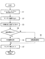
以下に、この制御装置50による車両用空調装置1の運転制御を、図7ないし図12に示すフロー図を参照して説明する。
図7は、車両用空調装置1のメイン制御フロー図であり、制御が開始されると、まずステップS1において、コントロールパネル52の設定を読み込み、更にステップS2において、各センサー53−62からの検出値を読み込む。これらの設定値および検出値に基づき、ステップS3において、目標吹出し温度Ttarを算出し、ステップS4に移行する。ここで、除湿運転ありか否かが判定され、「YES」であれば、ステップS5に移行して「冷房運転制御」に入り、「NO」であれば、ステップS6に移行して「暖房運転制御」に入る。その後、ステップS7において、各センサー53−62の検出値を出力し、スタート点に戻る。
Below, the operation control of the
FIG. 7 is a main control flow diagram of the
上記ステップS5において「冷房運転制御」に入ると、図8に示される冷房運転制御に移行される。冷房運転制御では、まずステップS10において、三方切替え弁29の流路が決定され、冷媒を車外凝縮器21側に流す回路に接続される。続いて、ステップS11において、電磁弁の開閉が決定され、電磁弁23が開、電磁弁31が閉とされる。これによって、冷房用サイクル27が設定される。
When “cooling operation control” is entered in step S5, the process proceeds to the cooling operation control shown in FIG. In the cooling operation control, first, in step S10, the flow path of the three-
引き続き、ステップS12において、電動圧縮機20の回転数、ステップS13において、内外気切替えダンパ6の切替えによる吸込みモード、ステップS14において、吹出しモード切替えダンパ15,16,17の切替えによる吹出しモード、ステップS15において、温調ダンパ11の開度、ステップS16において、ブロア7の駆動電圧、ステップS17において、車外ファン37の駆動電圧等がそれぞれ決定され、モータおよびアクチエータ63−68、70,71が駆動されることによって、車内温度が設定温度となるように冷房運転が実行される。その後、S1(=ステップS7)に戻り、冷房運転が継続される。
Subsequently, in step S12, the number of rotations of the
また、上記ステップS6において「暖房運転制御」に入ると、図9および図11に示される暖房運転制御に移行される。暖房運転制御では、まずステップS20において、外気温度Tambが、設定値a(例えば、aは氷点の0℃)以上か否か(Tamb≧a)が判定され、「YES」の場合、ステップS21に移行され、「NO」の場合、ステップS22に移行される。ステップS21においては、三方切替え弁29の流路が決定され、冷媒を第1暖房用回路30側に流す回路に接続される。続いて、ステップS23において、電磁弁の開閉が決定され、電磁弁23が閉、電磁弁31が開とされる。これにより、冷媒を第2暖房用回路35側、すなわち車外蒸発器33に流す着霜前の暖房用ヒートポンプサイクル36が設定される。
Further, when “heating operation control” is entered in step S6, the operation is shifted to the heating operation control shown in FIG. 9 and FIG. In the heating operation control, first in step S20, it is determined whether or not the outside air temperature Tamb is equal to or higher than a set value a (for example, a is 0 ° C. of freezing point) (Tamb ≧ a). If “YES”, the process proceeds to step S21. If "NO", the process moves to step S22. In step S21, the flow path of the three-
その後、ステップS24に移行され、ここで内外気切替えダンパ6が外気導入モードに決定され、ステップS25に移行される。ステップS25においては、車外蒸発器33に対する着霜の有無が判定される。この着霜判定は、車外蒸発器冷媒温度センサー58の検出値T1と外気温度センサー54の検出値Tambとの差が、設定値a以上か否か(T1−Tamb≧a)で判定され、「YES」(着霜あり)と判定されると、ステップS26に移行され、「NO」(着霜なし)と判定されると、ステップS27に移行される。
Thereafter, the process proceeds to step S24, where the inside / outside
着霜なしによりステップS27に移行されると、ここで、電動圧縮機20の回転数が決定され、更に、ステップS28において、吹出しモード切替えダンパ15,16,17の切替えるによる吹出しモード、ステップS29において、温調ダンパ11の開度、ステップS30において、ブロア7の駆動電圧、ステップS31において、車外ファン37の駆動電圧等が順次決定され、モータおよびアクチエータ63,65−68が駆動されることにより、車内温度が設定温度となるように暖房運転が実行される。その後、S1(=ステップS7)に戻り、暖房運転が継続される。
When the process proceeds to step S27 due to no frost formation, the rotational speed of the
一方、ステップS25で着霜ありと判定されてステップS26に移行すると、「除霜運転制御」に入り、図12に示されるように、除霜運転制御が実行される。
この除霜運転制御では、まずステップS80において、三方切替え弁29の流路が決定され、冷媒を第1暖房用回路30側に流す回路に接続される。続いて、ステップS81において、電磁弁の開閉が決定され、電磁弁23が開、電磁弁31が閉とされ、蒸発器が車内蒸発器9に切替えられた着霜後の暖房用ヒートポンプサイクル36が設定される。
On the other hand, when it is determined in step S25 that there is frost formation and the process proceeds to step S26, “defrost operation control” is entered, and defrost operation control is executed as shown in FIG.
In this defrosting operation control, first, in step S80, the flow path of the three-
引き続き、ステップS82において、電動圧縮機20の回転数、ステップS83において、内外気切替えダンパ4の切替えによる吸込みモード(この場合、内気循環モード)、ステップS84において、吹出しモード切替えダンパ15,16,17の切替えによる吹出しモード、ステップS85において、温調ダンパ11の開度、ステップS86において、ブロア7の駆動電圧、ステップS87において、車外ファン37の駆動電圧等が順次決定され、モータおよびアクチエータ63−68が駆動されることによって、車内温度が設定温度となるように、車内蒸発器9を用いた除湿暖房運転が実行される。
Subsequently, in step S82, the rotational speed of the
このように、除霜運転制御される間、空調装置1は除湿暖房運転され、この間に車外蒸発器33に着霜していた霜は、自然風もしくは車外ファン37を介して通風される外気によって自然にデフロストされる。そして、除霜運転制御が終了すると、S2(=ステップS32)に戻り、ここで、車外蒸発器フィン温度センサー(Tf)62の検出値が、設定値b以下か否か(Tf<b)が判定される。「YES」の場合は、デフロスト未完了と判断され、ステップS26に戻り、除霜運転制御が継続される。また、「NO」の場合は、ステップS33に移行して除霜運転制御が終了される。その後、S1(=ステップS7)に戻って、暖房運転が継続されることになる。
In this way, while the defrosting operation is controlled, the
一方、上記ステップS20において、「NO」と判定され、ステップS22に移行された場合、ここで、クーラント温度センサー61により検出されたクーラントの温度(または水温)Twが、設定値c以下か否か(Tw<c)が判定される。クーラントの温度Twが非常に高く、「NO」と判定されると、ステップS34に移行され、車両駆動用機器4のエンジンがオフとされ、更にステップS35でクーラントポンプ(ウォーターポンプ)41がオフ、ステップS36で電動圧縮機20がオフとされる。続いて、ステップS37で吹出しモード切替えダンパ15,16,17の切替えによる吹出しモード、ステップS38で温調ダンパ11の開度、ステップS39でブロア7の駆動電圧が決定され、モータおよびアクチエータ63,65,66が駆動される。これによって、排熱暖房が行われることになる。
On the other hand, if it is determined “NO” in step S20 and the process proceeds to step S22, whether or not the coolant temperature (or water temperature) Tw detected by the
また、ステップS22で「YES」と判定されると、ステップS40に移行され、クーラントの温度Twが、設定値d以上か否か(Tw>d)が判定される。クーラントの温度Twが非常に低く、「NO」と判定されると、ステップS41に移行され、設定値d以上の場合、「YES」と判定され、ステップS42に移行される。ステップS42では、三方切替え弁29の流路が決定され、冷媒を第1暖房用回路30側に流す回路に接続される。続いて、ステップS43において、電磁弁の開閉が決定され、電磁弁23が閉、電磁弁31が開とされ、これにより、冷媒を車外蒸発器33に流す着霜前の暖房用ヒートポンプサイクル36が設定される。
If “YES” is determined in the step S22, the process proceeds to a step S40 to determine whether or not the coolant temperature Tw is equal to or higher than a set value d (Tw> d). If the coolant temperature Tw is very low and the determination is “NO”, the process proceeds to step S41. If the coolant temperature Tw is equal to or greater than the set value d, the determination is “YES” and the process proceeds to step S42. In step S42, the flow path of the three-
その後、ステップS44に移行され、ここで、内外気切替えダンパ6が外気導入モードと決定され、ステップS45に移行される。ステップS45では、車外蒸発器33に対する着霜の有無が判定される。この着霜判定は、車外蒸発器冷媒温度センサー58の検出値T1と外気温度センサー54の検出値Tambとの差が、設定値e以上か否か(T1−Tamb≧e)で判定され、「YES」(着霜あり)と判定されると、ステップS46に移行され、「NO」(着霜なし)と判定されると、ステップS47に移行される。
Thereafter, the process proceeds to step S44, where the inside / outside
ステップS45で着霜なしと判定され、ステップS47に移行すると、ここで、車両駆動用機器4のエンジンがオフとされ、更にステップS48でクーラントポンプ(ウォーターポンプ)41がオフとされる。続いて、ステップS49において、電動圧縮機20の回転数、ステップS50において、吹出しモード切替えダンパ15,16,17の切替えるによる吹出しモード、ステップS51において、温調ダンパ11の開度、ステップS52において、ブロア7の駆動電圧、ステップS53において、車外ファン37の駆動電圧等がそれぞれ決定され、モータおよびアクチエータ63,65−68が駆動されることによって、車内温度が設定温度となるように暖房運転が実行される。その後、S1(=ステップS7)に戻り、暖房運転が継続される。
If it is determined in step S45 that there is no frost formation and the process proceeds to step S47, the engine of the
また、ステップS45で着霜ありと判定され、ステップS46に移行すると、ここで、車両駆動用機器4のエンジンがオンとされ、更にステップS54でクーラントポンプ(ウォーターポンプ)41がオンとされる。その後、ステップS55に移行して、「除霜運転制御」に入り、図12の通り除霜運転制御が実行される。なお、この除霜運転制御は、上述した通りであり、説明は省略する。一方、この除霜運転制御の間は、車両駆動用機器4のエンジンおよびクーラントポンプ41がオンとされているため、エンジンの排熱で温度上昇されたクーラントがラジエータ40に循環され、外気に放熱される。従って、その熱で加熱された温風を利用して車外蒸発器33の霜を効率よくデフロストすることができる。
If it is determined in step S45 that frost formation has occurred and the process proceeds to step S46, the engine of the
除霜運転制御が終了すると、S2(=ステップS56)に戻り、車外蒸発器フィン温度センサー(Tf)62の検出値が、設定値b以下か否か(Tf<b)が判定される。「YES」と判定された場合、デフロスト未完了と判断され、ステップS55に戻って、除霜運転制御が継続される。また、「NO」と判定された場合、ステップS57に移行して除霜運転制御が終了される。その後、S1(=ステップS7)に移行され、暖房運転が継続されることになる。 When the defrosting operation control ends, the process returns to S2 (= step S56), and it is determined whether or not the detected value of the outside-vehicle evaporator fin temperature sensor (Tf) 62 is equal to or less than the set value b (Tf <b). When it is determined as “YES”, it is determined that the defrost is not completed, the process returns to step S55, and the defrosting operation control is continued. Moreover, when it determines with "NO", it transfers to step S57 and a defrost operation control is complete | finished. Then, it transfers to S1 (= step S7) and heating operation is continued.
さらに、上記ステップS40において、クーラントの温度Twが非常に低く、「NO」と判定されてステップS41に移行された場合、ここで、車両駆動用機器4のエンジンがオンとされ、続くステップS58で、クーラントポンプ(ウォーターポンプ)41がオンとされる。次いで、ステップS59において、三方切替え弁29の流路が決定され、冷媒を第1暖房用回路30側に流す回路に接続される。更にステップS60において、電磁弁の開閉が決定され、電磁弁23が閉、電磁弁31が開とされる。これにより、冷媒を車外蒸発器33に流す着霜前の暖房用ヒートポンプサイクル36が設定される。
Furthermore, in step S40, when the coolant temperature Tw is very low and it is determined as “NO” and the process proceeds to step S41, the engine of the
その後、ステップS61に移行され、ここで、内外気切替えダンパ6が外気導入モードと決定され、ステップS62に移行される。ステップS62では、車外蒸発器33に対する着霜の有無が判定される。この着霜判定は、車外蒸発器冷媒温度センサー58の検出値T1と外気温度センサー54の検出値Tambとの差が、設定値e以上か否か(T1−Tamb≧e)で判定される。「YES」(着霜あり)と判定されると、ステップS63に移行され、「NO」(着霜なし)と判定されると、ステップS64に移行される。
Thereafter, the process proceeds to step S61, where the inside / outside
ステップS62で着霜なしと判定され、ステップS64に移行すると、ここで、電動圧縮機20の回転数が決定される。続いて、ステップS65において、吹出しモード切替えダンパ15,16,17の切替えるによる吹出しモード、ステップS66において、温調ダンパ11の開度、ステップS67において、ブロア7の駆動電圧、ステップS68において、車外ファン37の駆動電圧等が順次決定され、モータおよびアクチエータ63,65−68が駆動されることによって、車内温度が設定温度となるように暖房運転が実行される。その後、S1(=ステップS7)に戻り、暖房運転が継続される。
If it is determined in step S62 that there is no frost formation and the process proceeds to step S64, the rotational speed of the
また、ステップS62で着霜ありと判定されると、ステップS63に移行して「除霜運転制御」に入り、図12の通り除霜運転制御が実行される。この除霜運転制御は、上述した通りであり、説明は省略する。一方、この除霜運転制御の間は、車両駆動用機器4のエンジンおよびクーラントポンプ41がオンとされているため、エンジンの排熱により温度上昇されたクーラントがラジエータ40に循環され、外気に放熱される。従って、その熱で加熱された温風を利用して車外蒸発器33の霜を効率よく除霜することができる。
If it is determined in step S62 that there is frost formation, the process proceeds to step S63 to enter "defrosting operation control", and the defrosting operation control is executed as shown in FIG. This defrosting operation control is as described above, and a description thereof is omitted. On the other hand, during this defrosting operation control, since the engine of the
除霜運転制御が終了すると、S2(=ステップS69)に戻り、車外蒸発器フィン温度センサー(Tf)62の検出値が、設定値b以下か否か(Tf<b)が判定される。「YES」と判定された場合、デフロスト未完了と判断され、ステップS63に戻って、除霜運転制御が継続される。また、「NO」と判定された場合、ステップS70に移行して除霜運転制御が終了される。その後、S1(=ステップS7)に移行され、暖房運転が継続されることになる。 When the defrosting operation control is completed, the process returns to S2 (= step S69), and it is determined whether or not the detected value of the outside evaporator fin temperature sensor (Tf) 62 is equal to or less than the set value b (Tf <b). When it is determined as “YES”, it is determined that the defrost is not completed, the process returns to step S63, and the defrosting operation control is continued. Moreover, when it determines with "NO", it transfers to step S70 and a defrost operation control is complete | finished. Then, it transfers to S1 (= step S7) and heating operation is continued.
斯くして、本実施形態によると、以下の作用効果が奏される。
本実施形態のヒートポンプ式車両用空調装置1によれば、ブロア7からの空気流路8中に車内蒸発器9、ヒータコア10および温調ダンパ11等が順次配設され、車内蒸発器9およびヒータコア10で温調された空気をその下流側に設けられている複数の吹出し口のいずれかから車内に吹出して車室内を空調するHVACユニット2として、現行のガソリン車用の空調装置に適用されているHVACユニットを略同一構成のまま適用することができる。
Thus, according to the present embodiment, the following operational effects are achieved.
According to the heat pump type
さらに、現行のガソリン車用の空調装置に適用されている電動圧縮機20、車外凝縮器21、レシーバ22、第1膨張弁24およびHVACユニット2内に設けられた車内蒸発器9等からなる冷房用の冷凍サイクル27に対し、冷媒/クーラント熱交換器28、第1暖房用回路30、第2膨張弁32および車外蒸発器33を備えた第2暖房用回路35等の最小限の暖房用回路および機器を接続することにより、圧力条件が同一となる冷媒回路および機器類を共用化して暖房用のヒートポンプサイクル36を構成することができる。
Further, the cooling system includes an
このため、冷暖房双方の運転に耐え得る仕様のヒートポンプおよびHVACユニットを新たに開発することなく、ガソリン車に適用されている現行の車両用空調装置の冷房サイクルと圧力条件が同一となる冷媒回路や機器類をそのまま共用化し、圧力条件が異なる最小限の暖房用回路および機器を追加するだけで、構成が比較的簡素で低コストでかつ搭載性に優れ、電気自動車やハイブリッド車等に好適に適用できる信頼性の高い高効率のヒートポンプ式車両用空調装置1を提供することができる。
Therefore, without newly developing a heat pump and an HVAC unit that can withstand both cooling and heating operations, a refrigerant circuit that has the same pressure condition as the cooling cycle of the current vehicle air conditioner applied to a gasoline vehicle, By simply sharing equipment and adding a minimum heating circuit and equipment with different pressure conditions, the configuration is relatively simple, low cost, excellent mountability, and suitable for use in electric and hybrid vehicles. A highly reliable and highly efficient heat pump type
また、暖房用ヒートポンプサイクル36は、低外気温時、車外蒸発器33に着霜した場合に、第2暖房用回路35側への冷媒流れを遮断して車内蒸発器9側に冷媒を流し、車内蒸発器8を利用した除湿暖房に切替え可能とされている。このため、車外蒸発器33に対する着霜時には、蒸発器を車内蒸発器8側に切替えることにより、そのまま効率のよいヒートポンプ暖房運転を継続することができ、従って、暖房運転中に除霜運転に切替えることによる暖房運転の中断や消費電力のロスを解消することができる。
The heating
さらに、車内蒸発器9を利用した除湿暖房運転に切替えられた時、内気循環モードで運転されるようにしているため、車内蒸発器9を利用した除湿暖房運転時、比較的温度の高い車内空気を熱源としてヒートポンプ暖房運転を行うことができ、従って、暖房能力を十分に確保することができる。また、通常、低外気温時には、窓の曇りを防止するために外気導入モードにより暖房運転しているが、車内蒸発器9を利用した除湿暖房運転とすることによって、内気循環モードとしても窓曇りを防止することができる。
Further, when the operation is switched to the dehumidifying and heating operation using the in-
また、冷媒/クーラント熱交換器28は、電動圧縮機20から吐出されるホットガス冷媒と、クーラント循環回路5を循環するクーラントとが常時熱交換可能な構成とされているため、暖房運転中だけでなく、冷房運転中や除湿運転中でも常にヒータコア10に高温のクーラントを循環させながら運転することができる。従って、最大冷房運転時に、コントローラ側から急に吹出し温度変更指令が出された場合でも、温調ダンパ11で温調制御することにより瞬時に目標の吹出し温度に制御することが可能であり、温調制御の応答性を確保することができる。
In addition, the refrigerant /
また、本実施形態では、車外蒸発器33を、車外凝縮器用車外ファン37の通風路中の車外凝縮器21および/またはクーラント循環回路5に接続されている放熱用のラジエータ40の下流側に配設した構成としており、冬期の降雪時や積雪時等にも、車外蒸発器33に対する雪の付着や堆積等を車外凝縮器21および/またはラジエータ40によってブロックし、低減することができる。このため、雪の付着や堆積による車外蒸発器33の凍結を防止することができるとともに、車外蒸発器33による熱交換性能を確保し、暖房性能を向上することができる。加えて、ラジエータ40から放熱がある場合には、その熱を車外蒸発器33で吸熱することにより、暖房能力の一層の向上を図ることができる。
Further, in the present embodiment, the
さらに、暖房用ヒートポンプサイクル36による暖房時、車外蒸発器33に対して着霜が検知されたとき、第2暖房用回路35側への冷媒流れを遮断して車内蒸発器9側に冷媒を流通させ、暖房を継続するとともに、外気温度が所定値以上の場合、車外蒸発器33を外気によって自然デフロストし、外気温度が所定値以下の場合、ラジエータ40にクーラント循環回路5を介して昇温されたクーラントを循環させて外気に放熱させ、その熱を利用して車外蒸発器33をデフロストするようにしている。
Further, when frost formation is detected on the
このため、低外気温下の暖房運転時において、車外蒸発器33に対して着霜が検知された場合、エンジン、モータおよびインバータ等の車両駆動用機器4の排熱を利用してクーラントの温度を上昇させ、暖房性能を高めることができるとともに、ラジエータ40からその一部を放熱させ、加熱された温風を利用して車外蒸発器33を効率よく効果的に除霜することができる。従って、車両駆動用機器4の排熱を有効に利用して暖房および除霜を行うことができ、省動力化を図ることができる。
For this reason, when frost formation is detected in the
なお、本発明は、上記実施形態にかかる発明に限定されるものではなく、その要旨を逸脱しない範囲において、適宜変形が可能である。例えば、上記実施形態では、第1膨張弁24および第2膨張弁32の入口側に、それぞれ第1電磁弁23および第2電磁弁31を設けているが、これらの第1電磁弁23と第1膨張弁24および第2電磁弁31と第2膨張弁32は、それぞれが一体化された電磁開閉弁付き温度式自動膨張弁を用いた構成としてもよい。
In addition, this invention is not limited to the invention concerning the said embodiment, In the range which does not deviate from the summary, it can change suitably. For example, in the above-described embodiment, the first
また、上記実施形態では、吹出しモード切替えダンパが、デフダンパ15、フェイスダンパ16およびフットダンパ17からなる3ダンパ方式とされているが、デフダンパ15およびフェイスダンパ16を1つのダンパで兼用化し、該ダンパとフットダンパ17との2ダンパ方式としてもよい。さらに、上記実施形態では、クーラント循環回路5に三方制御弁42を設けた構成としているが、この三方制御弁42は、パラフィンワックス等が充填されたサーモエレメントにより、クーラントの温度に応答して流量割合を自動調整するサーモスタット弁としてもよく、この場合、制御装置50による弁の制御は不要となる。
In the above embodiment, the blowing mode switching damper is a three-damper system including the
1 ヒートポンプ式車両用空調装置
2 HVACユニット
4 車両駆動用機器
5 クーラント循環回路
9 車内蒸発器
10 ヒータコア
12 デフ吹出し口
13 フェイス吹出し口
14 フット吹出し口
20 電動圧縮機
21 車外凝縮器
22 レシーバ
24 第1膨張弁
26A 吐出回路(吐出配管)
27 冷房用冷凍サイクル
28 冷媒/クーラント熱交換器
29 三方切替え弁(切替え手段)
30 第1暖房用回路
32 第2膨張弁
33 車外蒸発器
35 第2暖房用回路
36 暖房用ヒートポンプサイクル
37 車外ファン
40 ラジエータ
DESCRIPTION OF
27 Refrigeration cycle for cooling 28 Refrigerant /
30
Claims (4)
前記ヒータコアに対して、エンジン、モータおよびインバータ等の車両駆動用機器を冷却するクーラントを循環可能なクーラント循環回路と、
電動圧縮機、車外凝縮器、レシーバ、第1膨張弁、前記車内蒸発器がこの順に接続されている冷房用の冷凍サイクルと、
前記電動圧縮機の吐出配管に設けられ、ホットガス冷媒と前記クーラント循環回路内を循環する前記クーラントとを熱交換する冷媒/クーラント熱交換器と、
前記車外凝縮器の入口側に設けられている切替え手段を介して前記レシーバに接続される第1暖房用回路と、
前記レシーバの出口側と前記電動圧縮機の吸入側との間に接続され、第2膨張弁および車外蒸発器が設けられている第2暖房用回路と、を備え、
前記電動圧縮機、前記冷媒/クーラント熱交換器、前記切替え手段、前記第1暖房用回路、前記レシーバ、前記第2膨張弁および前記車外蒸発器を備えた前記第2暖房用回路により暖房用のヒートポンプサイクルが構成され、前記冷媒/クーラント熱交換器で加熱された前記クーラントを前記ヒータコアに循環可能とし、
前記暖房用ヒートポンプサイクルによる暖房時、前記車外蒸発器に対して着霜が検知されたとき、前記第2暖房用回路側への冷媒流れを遮断して前記車内蒸発器側に冷媒を流通させ、該車内蒸発器を利用した除湿暖房に切替え可能とされていることを特徴とするヒートポンプ式車両用空調装置。 An HVAC unit that includes an in-vehicle evaporator and a heater core, and blows air temperature-adjusted by the in-vehicle evaporator and the heater core into a vehicle from any one of a plurality of outlets provided downstream thereof; ,
A coolant circulation circuit capable of circulating coolant for cooling a vehicle driving device such as an engine, a motor and an inverter with respect to the heater core;
An electric compressor, an external condenser, a receiver, a first expansion valve, a cooling cycle for cooling in which the in-vehicle evaporator is connected in this order;
A refrigerant / coolant heat exchanger provided in a discharge pipe of the electric compressor, for exchanging heat between the hot gas refrigerant and the coolant circulating in the coolant circulation circuit;
A first heating circuit connected to the receiver via switching means provided on the inlet side of the external condenser;
A second heating circuit connected between the outlet side of the receiver and the suction side of the electric compressor and provided with a second expansion valve and an outside evaporator,
For heating by the second heating circuit comprising the electric compressor, the refrigerant / coolant heat exchanger, the switching means, the first heating circuit, the receiver, the second expansion valve and the outside evaporator. A heat pump cycle is configured to allow circulation of the coolant heated by the refrigerant / coolant heat exchanger to the heater core;
During the heating by the heating heat pump cycle, when frost formation is detected for the outside evaporator, the refrigerant flow to the second heating circuit side is interrupted and the refrigerant is circulated to the in-vehicle evaporator side, A heat pump type vehicle air conditioner that can be switched to dehumidifying heating using the in-vehicle evaporator.
During the heating by the heating heat pump cycle, when frost formation is detected for the outside evaporator, the refrigerant flow to the second heating circuit side is interrupted and the refrigerant is circulated to the in-vehicle evaporator side, When heating is continued and the outside air temperature is equal to or higher than a predetermined value, the outside evaporator is naturally defrosted with outside air, and when the outside air temperature is equal to or lower than the predetermined value, the radiator is heated through the coolant circulation circuit. The heat pump type vehicle air conditioner according to claim 3, wherein a coolant is circulated to dissipate heat to the outside air, and the outside evaporator is defrosted by the heat.
Priority Applications (1)
| Application Number | Priority Date | Filing Date | Title |
|---|---|---|---|
| JP2011023162A JP2012162149A (en) | 2011-02-04 | 2011-02-04 | Heat pump type vehicular air conditioner |
Applications Claiming Priority (1)
| Application Number | Priority Date | Filing Date | Title |
|---|---|---|---|
| JP2011023162A JP2012162149A (en) | 2011-02-04 | 2011-02-04 | Heat pump type vehicular air conditioner |
Publications (1)
| Publication Number | Publication Date |
|---|---|
| JP2012162149A true JP2012162149A (en) | 2012-08-30 |
Family
ID=46842011
Family Applications (1)
| Application Number | Title | Priority Date | Filing Date |
|---|---|---|---|
| JP2011023162A Withdrawn JP2012162149A (en) | 2011-02-04 | 2011-02-04 | Heat pump type vehicular air conditioner |
Country Status (1)
| Country | Link |
|---|---|
| JP (1) | JP2012162149A (en) |
Cited By (6)
| Publication number | Priority date | Publication date | Assignee | Title |
|---|---|---|---|---|
| JP6218988B1 (en) * | 2016-07-27 | 2017-10-25 | 三菱電機株式会社 | Air conditioning apparatus, air conditioning method, and control program |
| CN109895599A (en) * | 2019-03-25 | 2019-06-18 | 江铃汽车股份有限公司 | Electric automobile heat-pump air-conditioning system and its control method |
| JP2019188852A (en) * | 2018-04-18 | 2019-10-31 | カルソニックカンセイ株式会社 | Air conditioner |
| CN110422028A (en) * | 2019-07-31 | 2019-11-08 | 上海马勒热系统有限公司 | Heat pump air conditioner for electric vehicle with defrosting function |
| CN113525018A (en) * | 2020-04-17 | 2021-10-22 | 浙江清华长三角研究院 | New energy automobile air conditioning system and control method thereof |
| WO2022233512A1 (en) * | 2021-05-04 | 2022-11-10 | Siemens Mobility GmbH | Vehicle for passenger transport with an electric, cooled drive device |
-
2011
- 2011-02-04 JP JP2011023162A patent/JP2012162149A/en not_active Withdrawn
Cited By (8)
| Publication number | Priority date | Publication date | Assignee | Title |
|---|---|---|---|---|
| JP6218988B1 (en) * | 2016-07-27 | 2017-10-25 | 三菱電機株式会社 | Air conditioning apparatus, air conditioning method, and control program |
| JP2019188852A (en) * | 2018-04-18 | 2019-10-31 | カルソニックカンセイ株式会社 | Air conditioner |
| CN109895599A (en) * | 2019-03-25 | 2019-06-18 | 江铃汽车股份有限公司 | Electric automobile heat-pump air-conditioning system and its control method |
| CN109895599B (en) * | 2019-03-25 | 2023-09-15 | 江铃汽车股份有限公司 | Electric automobile heat pump air conditioning system and control method thereof |
| CN110422028A (en) * | 2019-07-31 | 2019-11-08 | 上海马勒热系统有限公司 | Heat pump air conditioner for electric vehicle with defrosting function |
| CN113525018A (en) * | 2020-04-17 | 2021-10-22 | 浙江清华长三角研究院 | New energy automobile air conditioning system and control method thereof |
| CN113525018B (en) * | 2020-04-17 | 2023-07-04 | 浙江清华长三角研究院 | New energy automobile air conditioning system and control method thereof |
| WO2022233512A1 (en) * | 2021-05-04 | 2022-11-10 | Siemens Mobility GmbH | Vehicle for passenger transport with an electric, cooled drive device |
Similar Documents
| Publication | Publication Date | Title |
|---|---|---|
| JP5611072B2 (en) | Heat pump air conditioner for vehicle and defrosting method thereof | |
| JP6323489B2 (en) | Heat pump system | |
| JP6791052B2 (en) | Air conditioner | |
| JP6257940B2 (en) | Heat pump type vehicle air conditioning system and defrosting method thereof | |
| US9250005B2 (en) | Air conditioner for vehicle with heat pump cycle | |
| JP6836209B2 (en) | Vehicle cooling system | |
| WO2014188674A1 (en) | Refrigeration cycle device | |
| WO2012060132A1 (en) | Heat-pump vehicular air conditioner and defrosting method thereof | |
| WO2013094144A1 (en) | Air-conditioning apparatus for vehicles | |
| JP2019045034A (en) | Refrigeration cycle device | |
| JP7173064B2 (en) | thermal management system | |
| JP2015000620A (en) | Heat pump type vehicular air-conditioning system | |
| JP6391907B2 (en) | Vehicle air conditioner and operation method thereof | |
| JP5935625B2 (en) | Refrigeration cycle controller | |
| JP2011195021A (en) | Heat pump device for vehicle | |
| JP2012162149A (en) | Heat pump type vehicular air conditioner | |
| CN113226814A (en) | Air conditioner for vehicle | |
| JP6037773B2 (en) | Heat pump type air conditioner for vehicle and vehicle | |
| JPH07232547A (en) | Air conditioner for vehicle | |
| WO2021177057A1 (en) | Vehicle air conditioner | |
| JP7099899B2 (en) | Vehicle air conditioner | |
| JP2004042759A (en) | Air conditioner for automobile | |
| CN111033148A (en) | Refrigeration cycle device | |
| CN110475683B (en) | Air conditioning apparatus | |
| JP7053906B1 (en) | Temperature control system |
Legal Events
| Date | Code | Title | Description |
|---|---|---|---|
| A300 | Withdrawal of application because of no request for examination |
Free format text: JAPANESE INTERMEDIATE CODE: A300 Effective date: 20140513 |