JP6323489B2 - Heat pump system - Google Patents
Heat pump system Download PDFInfo
- Publication number
- JP6323489B2 JP6323489B2 JP2016075387A JP2016075387A JP6323489B2 JP 6323489 B2 JP6323489 B2 JP 6323489B2 JP 2016075387 A JP2016075387 A JP 2016075387A JP 2016075387 A JP2016075387 A JP 2016075387A JP 6323489 B2 JP6323489 B2 JP 6323489B2
- Authority
- JP
- Japan
- Prior art keywords
- refrigerant
- compressor
- heat exchanger
- unit
- internal heat
- Prior art date
- Legal status (The legal status is an assumption and is not a legal conclusion. Google has not performed a legal analysis and makes no representation as to the accuracy of the status listed.)
- Active
Links
Images


Classifications
-
- F—MECHANICAL ENGINEERING; LIGHTING; HEATING; WEAPONS; BLASTING
- F25—REFRIGERATION OR COOLING; COMBINED HEATING AND REFRIGERATION SYSTEMS; HEAT PUMP SYSTEMS; MANUFACTURE OR STORAGE OF ICE; LIQUEFACTION SOLIDIFICATION OF GASES
- F25B—REFRIGERATION MACHINES, PLANTS OR SYSTEMS; COMBINED HEATING AND REFRIGERATION SYSTEMS; HEAT PUMP SYSTEMS
- F25B41/00—Fluid-circulation arrangements
- F25B41/20—Disposition of valves, e.g. of on-off valves or flow control valves
- F25B41/24—Arrangement of shut-off valves for disconnecting a part of the refrigerant cycle, e.g. an outdoor part
-
- B—PERFORMING OPERATIONS; TRANSPORTING
- B60—VEHICLES IN GENERAL
- B60H—ARRANGEMENTS OF HEATING, COOLING, VENTILATING OR OTHER AIR-TREATING DEVICES SPECIALLY ADAPTED FOR PASSENGER OR GOODS SPACES OF VEHICLES
- B60H1/00—Heating, cooling or ventilating [HVAC] devices
- B60H1/00642—Control systems or circuits; Control members or indication devices for heating, cooling or ventilating devices
- B60H1/00814—Control systems or circuits characterised by their output, for controlling particular components of the heating, cooling or ventilating installation
- B60H1/00878—Control systems or circuits characterised by their output, for controlling particular components of the heating, cooling or ventilating installation the components being temperature regulating devices
- B60H1/00899—Controlling the flow of liquid in a heat pump system
- B60H1/00914—Controlling the flow of liquid in a heat pump system where the flow direction of the refrigerant does not change and there is a bypass of the condenser
-
- B—PERFORMING OPERATIONS; TRANSPORTING
- B60—VEHICLES IN GENERAL
- B60H—ARRANGEMENTS OF HEATING, COOLING, VENTILATING OR OTHER AIR-TREATING DEVICES SPECIALLY ADAPTED FOR PASSENGER OR GOODS SPACES OF VEHICLES
- B60H1/00—Heating, cooling or ventilating [HVAC] devices
- B60H1/00642—Control systems or circuits; Control members or indication devices for heating, cooling or ventilating devices
- B60H1/00814—Control systems or circuits characterised by their output, for controlling particular components of the heating, cooling or ventilating installation
- B60H1/00878—Control systems or circuits characterised by their output, for controlling particular components of the heating, cooling or ventilating installation the components being temperature regulating devices
- B60H1/00899—Controlling the flow of liquid in a heat pump system
- B60H1/00921—Controlling the flow of liquid in a heat pump system where the flow direction of the refrigerant does not change and there is an extra subcondenser, e.g. in an air duct
-
- B—PERFORMING OPERATIONS; TRANSPORTING
- B60—VEHICLES IN GENERAL
- B60H—ARRANGEMENTS OF HEATING, COOLING, VENTILATING OR OTHER AIR-TREATING DEVICES SPECIALLY ADAPTED FOR PASSENGER OR GOODS SPACES OF VEHICLES
- B60H1/00—Heating, cooling or ventilating [HVAC] devices
- B60H1/22—Heating, cooling or ventilating [HVAC] devices the heat being derived otherwise than from the propulsion plant
-
- F—MECHANICAL ENGINEERING; LIGHTING; HEATING; WEAPONS; BLASTING
- F25—REFRIGERATION OR COOLING; COMBINED HEATING AND REFRIGERATION SYSTEMS; HEAT PUMP SYSTEMS; MANUFACTURE OR STORAGE OF ICE; LIQUEFACTION SOLIDIFICATION OF GASES
- F25B—REFRIGERATION MACHINES, PLANTS OR SYSTEMS; COMBINED HEATING AND REFRIGERATION SYSTEMS; HEAT PUMP SYSTEMS
- F25B1/00—Compression machines, plants or systems with non-reversible cycle
- F25B1/10—Compression machines, plants or systems with non-reversible cycle with multi-stage compression
-
- F—MECHANICAL ENGINEERING; LIGHTING; HEATING; WEAPONS; BLASTING
- F25—REFRIGERATION OR COOLING; COMBINED HEATING AND REFRIGERATION SYSTEMS; HEAT PUMP SYSTEMS; MANUFACTURE OR STORAGE OF ICE; LIQUEFACTION SOLIDIFICATION OF GASES
- F25B—REFRIGERATION MACHINES, PLANTS OR SYSTEMS; COMBINED HEATING AND REFRIGERATION SYSTEMS; HEAT PUMP SYSTEMS
- F25B13/00—Compression machines, plants or systems, with reversible cycle
-
- F—MECHANICAL ENGINEERING; LIGHTING; HEATING; WEAPONS; BLASTING
- F25—REFRIGERATION OR COOLING; COMBINED HEATING AND REFRIGERATION SYSTEMS; HEAT PUMP SYSTEMS; MANUFACTURE OR STORAGE OF ICE; LIQUEFACTION SOLIDIFICATION OF GASES
- F25B—REFRIGERATION MACHINES, PLANTS OR SYSTEMS; COMBINED HEATING AND REFRIGERATION SYSTEMS; HEAT PUMP SYSTEMS
- F25B25/00—Machines, plants or systems, using a combination of modes of operation covered by two or more of the groups F25B1/00 - F25B23/00
- F25B25/005—Machines, plants or systems, using a combination of modes of operation covered by two or more of the groups F25B1/00 - F25B23/00 using primary and secondary systems
-
- F—MECHANICAL ENGINEERING; LIGHTING; HEATING; WEAPONS; BLASTING
- F25—REFRIGERATION OR COOLING; COMBINED HEATING AND REFRIGERATION SYSTEMS; HEAT PUMP SYSTEMS; MANUFACTURE OR STORAGE OF ICE; LIQUEFACTION SOLIDIFICATION OF GASES
- F25B—REFRIGERATION MACHINES, PLANTS OR SYSTEMS; COMBINED HEATING AND REFRIGERATION SYSTEMS; HEAT PUMP SYSTEMS
- F25B39/00—Evaporators; Condensers
- F25B39/04—Condensers
-
- F—MECHANICAL ENGINEERING; LIGHTING; HEATING; WEAPONS; BLASTING
- F25—REFRIGERATION OR COOLING; COMBINED HEATING AND REFRIGERATION SYSTEMS; HEAT PUMP SYSTEMS; MANUFACTURE OR STORAGE OF ICE; LIQUEFACTION SOLIDIFICATION OF GASES
- F25B—REFRIGERATION MACHINES, PLANTS OR SYSTEMS; COMBINED HEATING AND REFRIGERATION SYSTEMS; HEAT PUMP SYSTEMS
- F25B40/00—Subcoolers, desuperheaters or superheaters
-
- F—MECHANICAL ENGINEERING; LIGHTING; HEATING; WEAPONS; BLASTING
- F25—REFRIGERATION OR COOLING; COMBINED HEATING AND REFRIGERATION SYSTEMS; HEAT PUMP SYSTEMS; MANUFACTURE OR STORAGE OF ICE; LIQUEFACTION SOLIDIFICATION OF GASES
- F25B—REFRIGERATION MACHINES, PLANTS OR SYSTEMS; COMBINED HEATING AND REFRIGERATION SYSTEMS; HEAT PUMP SYSTEMS
- F25B41/00—Fluid-circulation arrangements
- F25B41/20—Disposition of valves, e.g. of on-off valves or flow control valves
-
- F—MECHANICAL ENGINEERING; LIGHTING; HEATING; WEAPONS; BLASTING
- F25—REFRIGERATION OR COOLING; COMBINED HEATING AND REFRIGERATION SYSTEMS; HEAT PUMP SYSTEMS; MANUFACTURE OR STORAGE OF ICE; LIQUEFACTION SOLIDIFICATION OF GASES
- F25B—REFRIGERATION MACHINES, PLANTS OR SYSTEMS; COMBINED HEATING AND REFRIGERATION SYSTEMS; HEAT PUMP SYSTEMS
- F25B43/00—Arrangements for separating or purifying gases or liquids; Arrangements for vaporising the residuum of liquid refrigerant, e.g. by heat
- F25B43/006—Accumulators
-
- F—MECHANICAL ENGINEERING; LIGHTING; HEATING; WEAPONS; BLASTING
- F25—REFRIGERATION OR COOLING; COMBINED HEATING AND REFRIGERATION SYSTEMS; HEAT PUMP SYSTEMS; MANUFACTURE OR STORAGE OF ICE; LIQUEFACTION SOLIDIFICATION OF GASES
- F25B—REFRIGERATION MACHINES, PLANTS OR SYSTEMS; COMBINED HEATING AND REFRIGERATION SYSTEMS; HEAT PUMP SYSTEMS
- F25B6/00—Compression machines, plants or systems, with several condenser circuits
- F25B6/02—Compression machines, plants or systems, with several condenser circuits arranged in parallel
-
- B—PERFORMING OPERATIONS; TRANSPORTING
- B60—VEHICLES IN GENERAL
- B60H—ARRANGEMENTS OF HEATING, COOLING, VENTILATING OR OTHER AIR-TREATING DEVICES SPECIALLY ADAPTED FOR PASSENGER OR GOODS SPACES OF VEHICLES
- B60H1/00—Heating, cooling or ventilating [HVAC] devices
- B60H1/00642—Control systems or circuits; Control members or indication devices for heating, cooling or ventilating devices
- B60H1/00814—Control systems or circuits characterised by their output, for controlling particular components of the heating, cooling or ventilating installation
- B60H1/00878—Control systems or circuits characterised by their output, for controlling particular components of the heating, cooling or ventilating installation the components being temperature regulating devices
- B60H2001/00928—Control systems or circuits characterised by their output, for controlling particular components of the heating, cooling or ventilating installation the components being temperature regulating devices comprising a secondary circuit
-
- B—PERFORMING OPERATIONS; TRANSPORTING
- B60—VEHICLES IN GENERAL
- B60H—ARRANGEMENTS OF HEATING, COOLING, VENTILATING OR OTHER AIR-TREATING DEVICES SPECIALLY ADAPTED FOR PASSENGER OR GOODS SPACES OF VEHICLES
- B60H1/00—Heating, cooling or ventilating [HVAC] devices
- B60H1/00642—Control systems or circuits; Control members or indication devices for heating, cooling or ventilating devices
- B60H1/00814—Control systems or circuits characterised by their output, for controlling particular components of the heating, cooling or ventilating installation
- B60H1/00878—Control systems or circuits characterised by their output, for controlling particular components of the heating, cooling or ventilating installation the components being temperature regulating devices
- B60H2001/00957—Control systems or circuits characterised by their output, for controlling particular components of the heating, cooling or ventilating installation the components being temperature regulating devices comprising locations with heat exchange within the refrigerant circuit itself, e.g. cross-, counter-, or parallel heat exchange
-
- F—MECHANICAL ENGINEERING; LIGHTING; HEATING; WEAPONS; BLASTING
- F25—REFRIGERATION OR COOLING; COMBINED HEATING AND REFRIGERATION SYSTEMS; HEAT PUMP SYSTEMS; MANUFACTURE OR STORAGE OF ICE; LIQUEFACTION SOLIDIFICATION OF GASES
- F25B—REFRIGERATION MACHINES, PLANTS OR SYSTEMS; COMBINED HEATING AND REFRIGERATION SYSTEMS; HEAT PUMP SYSTEMS
- F25B2313/00—Compression machines, plants or systems with reversible cycle not otherwise provided for
- F25B2313/023—Compression machines, plants or systems with reversible cycle not otherwise provided for using multiple indoor units
- F25B2313/0233—Compression machines, plants or systems with reversible cycle not otherwise provided for using multiple indoor units in parallel arrangements
-
- F—MECHANICAL ENGINEERING; LIGHTING; HEATING; WEAPONS; BLASTING
- F25—REFRIGERATION OR COOLING; COMBINED HEATING AND REFRIGERATION SYSTEMS; HEAT PUMP SYSTEMS; MANUFACTURE OR STORAGE OF ICE; LIQUEFACTION SOLIDIFICATION OF GASES
- F25B—REFRIGERATION MACHINES, PLANTS OR SYSTEMS; COMBINED HEATING AND REFRIGERATION SYSTEMS; HEAT PUMP SYSTEMS
- F25B2313/00—Compression machines, plants or systems with reversible cycle not otherwise provided for
- F25B2313/027—Compression machines, plants or systems with reversible cycle not otherwise provided for characterised by the reversing means
- F25B2313/02741—Compression machines, plants or systems with reversible cycle not otherwise provided for characterised by the reversing means using one four-way valve
-
- F—MECHANICAL ENGINEERING; LIGHTING; HEATING; WEAPONS; BLASTING
- F25—REFRIGERATION OR COOLING; COMBINED HEATING AND REFRIGERATION SYSTEMS; HEAT PUMP SYSTEMS; MANUFACTURE OR STORAGE OF ICE; LIQUEFACTION SOLIDIFICATION OF GASES
- F25B—REFRIGERATION MACHINES, PLANTS OR SYSTEMS; COMBINED HEATING AND REFRIGERATION SYSTEMS; HEAT PUMP SYSTEMS
- F25B2600/00—Control issues
- F25B2600/21—Refrigerant outlet evaporator temperature
-
- F—MECHANICAL ENGINEERING; LIGHTING; HEATING; WEAPONS; BLASTING
- F25—REFRIGERATION OR COOLING; COMBINED HEATING AND REFRIGERATION SYSTEMS; HEAT PUMP SYSTEMS; MANUFACTURE OR STORAGE OF ICE; LIQUEFACTION SOLIDIFICATION OF GASES
- F25B—REFRIGERATION MACHINES, PLANTS OR SYSTEMS; COMBINED HEATING AND REFRIGERATION SYSTEMS; HEAT PUMP SYSTEMS
- F25B2600/00—Control issues
- F25B2600/25—Control of valves
- F25B2600/2507—Flow-diverting valves
Description
本発明は、冷媒を循環させて、空気を加熱および冷却するヒートポンプシステムに関する。 The present invention relates to a heat pump system that circulates a refrigerant to heat and cool air.
従来のヒートポンプシステムは、たとえばカーエアコンに用いられ、冷凍サイクルを含んで構成される。冷凍サイクルに用いられる熱交換器は、凝縮器および蒸発器などとして機能し、内部を流れる冷媒と外部を流れる空気とを熱交換するように構成される。 A conventional heat pump system is used, for example, in a car air conditioner and includes a refrigeration cycle. The heat exchanger used in the refrigeration cycle functions as a condenser, an evaporator, and the like, and is configured to exchange heat between the refrigerant flowing inside and the air flowing outside.
またヒートポンプシステムは、車室外に設けられる室外熱交換器を備えている。室外熱交換器は、室外器とも称され、暖房時は蒸発器として機能し、冷房時は凝縮器として機能する。蒸発器として機能する場合、乾き度が小さい冷媒が室外器に流入する。そして冷媒が室外器内を流れるにつれて、空気から吸熱して徐々に蒸発が進み、気体の冷媒が占める割合が増えて、乾き度が大きい冷媒が流出する(たとえば特許文献1参照)。 The heat pump system includes an outdoor heat exchanger provided outside the vehicle compartment. The outdoor heat exchanger is also called an outdoor unit, and functions as an evaporator during heating and functions as a condenser during cooling. When functioning as an evaporator, a refrigerant having a low dryness flows into the outdoor unit. As the refrigerant flows in the outdoor unit, heat is absorbed from the air and evaporation gradually proceeds, and the ratio of the gaseous refrigerant increases, and the refrigerant having a high dryness flows out (see, for example, Patent Document 1).
前述の特許文献1に記載の冷凍サイクルは、圧縮機前にアキュムレータが設けられている。アキュムレータ内では二相冷媒は気液分離され、基本的にはガス冷媒のみ流出する。ただし、実用上、液冷媒に溶け込んだ圧縮機の潤滑油も戻す必要があるため、出口配管の途中には潤滑油の戻し穴が設けられている。そのため、圧縮機吸入前に冷媒過熱度が取れず、蒸発器のエンタルピ差が小さくなり、特に冷房時において、サイクル効率が悪化してしまうという問題がある。
In the refrigeration cycle described in
また、冬場の暖房時には室外器が蒸発器として機能するが、その際、室外器には二相の冷媒を多数のチューブに分配しなければならない。多数のチューブに二相の冷媒を均等に分配することは非常に困難であり、特定のチューブに液冷媒の流れが集中してしまうので、室外器の有効利用面積が低下するといった問題がある。また暖房時に外気が高湿度条件下では、室外器の表面が着霜し、暖房性能が低下するという問題もある。 In addition, the outdoor unit functions as an evaporator during heating in winter, and at that time, the two-phase refrigerant must be distributed to a number of tubes in the outdoor unit. It is very difficult to evenly distribute the two-phase refrigerant to a large number of tubes, and the flow of the liquid refrigerant concentrates on a specific tube, so that there is a problem that the effective use area of the outdoor unit is reduced. In addition, when the outside air is in a high humidity condition during heating, there is a problem that the surface of the outdoor unit is frosted and the heating performance is deteriorated.
そこで、本発明は前述の問題点を鑑みてなされたものであり、冷房性能および暖房性能を向上することができるヒートポンプシステムを提供することを目的とする。 Then, this invention is made | formed in view of the above-mentioned problem, and it aims at providing the heat pump system which can improve cooling performance and heating performance.
本発明は前述の目的を達成するために以下の技術的手段を採用する。 The present invention employs the following technical means in order to achieve the aforementioned object.
開示された技術の一つは、冷媒が流れる経路を変更する流路変更部(21〜23,25)を含み、流路変更部は、圧縮機(13)、室外器(16)、凝縮器(14)、内部熱交換器(20)の高圧流路(20a)、減圧部(17,18)、蒸発器(15)、アキュムレータ(19)、内部熱交換器の低圧流路、圧縮機の順で冷媒が循環する冷房経路と、圧縮機、凝縮器、内部熱交換器の高圧流路、減圧部、室外器、アキュムレータ、内部熱交換器の低圧流路、圧縮機の順で冷媒が循環する暖房経路と、を変更することを特徴とするヒートポンプシステムである。また、アキュムレータ(19)は、分離したガス冷媒を流出させるガス冷媒流路(19a)と、分離した液冷媒を流出させる液冷媒流路(19b)と、を備え、ガス冷媒流路および液冷媒流路のうち少なくとも液冷媒流路は、内部熱交換器(20)の低圧流路(20b)に接続されていることを特徴とするヒートポンプシステムである。 One of the disclosed technologies includes a flow path changing unit (21 to 23, 25) that changes a path through which the refrigerant flows. The flow path changing unit includes a compressor (13), an outdoor unit (16), and a condenser. (14), the high pressure flow path (20a ) of the internal heat exchanger (20), the decompression section (17, 18), the evaporator (15), the accumulator (19), the low pressure flow path of the internal heat exchanger, the compressor a cooling path in which the refrigerant circulates in the order, a compressor, a condenser, the high pressure flow path of the internal heat exchanger, pressure reducing unit, outdoor unit, an accumulator, a low-pressure flow path of the internal heat exchanger, the refrigerant in the order of the compressor circulates It is a heat pump system characterized by changing a heating path to be performed. Further, the accumulator (19) includes a gas refrigerant channel (19a) through which the separated gas refrigerant flows out and a liquid refrigerant channel (19b) through which the separated liquid refrigerant flows out, and the gas refrigerant channel and the liquid refrigerant At least the liquid refrigerant channel among the channels is connected to the low pressure channel (20b) of the internal heat exchanger (20).
このような本発明に従えば、冷房時には冷房経路で冷媒が循環するように制御され、暖房時には暖房経路で冷媒が循環するように制御される。冷房経路および暖房経路では、内部熱交換器を冷媒が通過する。内部熱交換器によって、凝縮器として機能する熱交換器の下流側を流れる高圧冷媒と、蒸発器として機能する熱交換器の下流側の低圧冷媒とが熱交換される。これによって蒸発器として作動する熱交換器に流入する冷媒の冷媒乾き度を下げるとともに、熱交換器を流出する冷媒の冷媒乾き度も下げることができる。したがって蒸発器として機能する熱交換器内の冷媒乾き度の作動域を低くすることができる。これによって、熱交換器へ流入する液冷媒の体積比率が増加し、熱交換器内の液冷媒分配を改善することができる。 According to the present invention as described above, the refrigerant is controlled to circulate through the cooling path during cooling, and the refrigerant is controlled to circulate through the heating path during heating. In the cooling path and the heating path, the refrigerant passes through the internal heat exchanger. The internal heat exchanger exchanges heat between the high-pressure refrigerant flowing downstream of the heat exchanger functioning as a condenser and the low-pressure refrigerant downstream of the heat exchanger functioning as an evaporator. As a result, the refrigerant dryness of the refrigerant flowing into the heat exchanger operating as an evaporator can be lowered, and the refrigerant dryness of the refrigerant flowing out of the heat exchanger can also be lowered. Therefore, the operating range of the refrigerant dryness in the heat exchanger functioning as an evaporator can be lowered. As a result, the volume ratio of the liquid refrigerant flowing into the heat exchanger increases, and the liquid refrigerant distribution in the heat exchanger can be improved.
また本発明では、蒸発器として機能する熱交換器の下流側に内部熱交換器を設けているので、蒸発器流出部の冷媒乾き度を低くすることができる。これによって、熱交換器を構成する各チューブ流出部において、冷媒乾き度がばらついても過熱度領域が生成されることを大幅に低減することができる。 Moreover, in this invention, since the internal heat exchanger is provided in the downstream of the heat exchanger which functions as an evaporator, the refrigerant dryness of an evaporator outflow part can be made low. As a result, it is possible to greatly reduce the generation of the superheat degree region even if the refrigerant dryness varies in each tube outflow portion constituting the heat exchanger.
さらに本発明では、内部熱交換器を用いて、特に室外器が蒸発器として作動する際の冷媒乾き度を低冷媒乾き度域へ変化させることで、蒸発時の冷媒圧損の低減と熱交換面積の有効活用という通常相反する課題を両立させることが可能となる。また、低乾き度域での作動により、室外器内を流れる冷媒の平均密度を大きくできるため、冷媒の流速を低減でき、冷媒圧損低減にも効果を発揮する。さらに、室外器から内部熱交換器への冷媒配管における冷媒圧損も従来よりも低乾き度で流れるため低減することができる。このため、内部熱交換器が構成されていても冷媒圧損の低減が可能となる。 Furthermore, in the present invention, by using the internal heat exchanger, particularly by changing the refrigerant dryness when the outdoor unit operates as an evaporator to a low refrigerant dryness range, the refrigerant pressure loss during evaporation and the heat exchange area are reduced. This makes it possible to reconcile the normally conflicting issues of effective use of. Moreover, since the average density of the refrigerant flowing in the outdoor unit can be increased by operating in the low dryness region, the flow rate of the refrigerant can be reduced, and the refrigerant pressure loss can be reduced. Furthermore, the refrigerant pressure loss in the refrigerant piping from the outdoor unit to the internal heat exchanger can also be reduced because it flows at a lower dryness than before. For this reason, even if the internal heat exchanger is configured, the refrigerant pressure loss can be reduced.
前述の効果は蒸発器として機能させる室外器だけでなく、冷房時の蒸発器においても同じことが言える。内部熱交換器によって蒸発器の作動乾き度を低乾き度域にすることで、蒸発器の冷媒パスを例えば全パスに減らしても均一な吹き出し温度の確保と、低圧損化の両立が可能となり、アキュムレータサイクルによる冷房時の効率悪化を抑制できる。 The same can be said for not only the outdoor unit that functions as an evaporator but also the evaporator during cooling. By using the internal heat exchanger to reduce the operating dryness of the evaporator to a low dryness range, even if the refrigerant path of the evaporator is reduced to, for example, all paths, it is possible to achieve both a uniform blowing temperature and low pressure loss. The deterioration of efficiency during cooling due to the accumulator cycle can be suppressed.
このような本発明に従えば、暖房経路では、凝縮器流出後の液冷媒と、アキュムレータ流出後の液冷媒とを、内部熱交換器で熱交換することによって、凝縮器で凝縮された冷媒のエンタルピを下げることができる。これにより、室外器入口の冷媒乾き度を低くすることができる。室外器入口冷媒乾き度を低くできると、流入する液冷媒の体積が増加し、室外器内の冷媒分配性を改善することが可能となる。したがって室外器における熱交換性能を向上することができる。 According to the present invention, in the heating path, the liquid refrigerant after flowing out of the condenser and the liquid refrigerant after flowing out of the accumulator are heat-exchanged by the internal heat exchanger, so that the refrigerant condensed in the condenser is exchanged. Enthalpy can be lowered. Thereby, the refrigerant dryness of an outdoor unit entrance can be made low. When the outdoor unit inlet refrigerant dryness can be lowered, the volume of the flowing liquid refrigerant increases, and the refrigerant distribution in the outdoor unit can be improved. Therefore, the heat exchange performance in the outdoor unit can be improved.
また冷房経路では、内部熱交換器で熱交換することによって、室外器で冷却された冷媒を、アキュムレータからの液冷媒によってさらに冷却することができる。その後、内部熱交換器の高圧流路を通過した冷媒は、減圧部、蒸発器に流れる。内部熱交換器で冷媒はさらに冷却されているので、蒸発器内を流れる冷媒の平均乾き度を低減することができる。これによって蒸発器内の冷媒圧損を低減することができ、さらに、蒸発器内に過熱度領域の発生の抑制になるので、蒸発器の性能が向上し、システム効率を改善することができる。 In the cooling path, the refrigerant cooled by the outdoor unit can be further cooled by the liquid refrigerant from the accumulator by exchanging heat with the internal heat exchanger. Thereafter, the refrigerant that has passed through the high-pressure channel of the internal heat exchanger flows to the decompression unit and the evaporator. Since the refrigerant is further cooled by the internal heat exchanger, the average dryness of the refrigerant flowing in the evaporator can be reduced. As a result, the refrigerant pressure loss in the evaporator can be reduced, and the superheat degree region is suppressed from being generated in the evaporator, so that the performance of the evaporator is improved and the system efficiency can be improved.
また、本発明の圧縮機、室外器、内部熱交換器の高圧流路、減圧部、蒸発器、内部熱交換器の低圧流路、アキュムレータ、圧縮機の順で接続される構成においても、蒸発器として作動する熱交換器の作動乾き度を出入口側ともに低乾き度側で作動させることができるため前述の構成と同様の効果が発揮できる。 Also, in the configuration in which the compressor, the outdoor unit, the internal heat exchanger, the decompression unit, the evaporator, the low pressure channel of the internal heat exchanger, the accumulator, and the compressor are connected in this order according to the present invention, Since the heat dryness of the heat exchanger that operates as a heat exchanger can be operated on the low dryness side on both the entrance and exit sides, the same effect as the above-described configuration can be exhibited.
なお、前述の各手段の括弧内の符号は、後述する実施形態に記載の具体的手段との対応関係を示す一例である。 In addition, the code | symbol in the bracket | parenthesis of each above-mentioned means is an example which shows a corresponding relationship with the specific means as described in embodiment mentioned later.
以下、図面を参照しながら本発明を実施するための形態を、複数の形態を用いて説明する。各実施形態で先行する実施形態で説明している事項に対応している部分には同一の参照符を付すか、または先行の参照符号に一文字追加し、重複する説明を略する場合がある。また各実施形態にて構成の一部を説明している場合、構成の他の部分は、先行して説明している実施形態と同様とする。各実施形態で具体的に説明している部分の組合せばかりではなく、特に組合せに支障が生じなければ、実施形態同士を部分的に組合せることも可能である。 DESCRIPTION OF EMBODIMENTS Hereinafter, embodiments for carrying out the present invention will be described using a plurality of embodiments with reference to the drawings. In some embodiments, portions corresponding to the matters described in the preceding embodiments may be given the same reference numerals, or one letter may be added to the preceding reference numerals, and overlapping descriptions may be omitted. In addition, when a part of the configuration is described in each embodiment, the other parts of the configuration are the same as those of the embodiment described in advance. In addition to the combination of parts specifically described in each embodiment, the embodiments may be partially combined as long as the combination does not hinder the combination.
(第1実施形態)
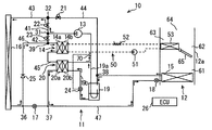
本発明の第1実施形態に関して、図1〜図12を用いて説明する。本実施形態のヒートポンプシステム10は、ヒートポンプサイクル11および空調ユニット12を備え、図1に示す構成部品を用いて空調運転を行うものである。ヒートポンプシステム10は、車両、例えばハイブリッド自動車、電気自動車、燃料電池車等に使用することができる。ヒートポンプシステム10は、少なくとも暖房運転および冷房運転を行うように構成されている。図1に示すヒートポンプサイクル11は、ヒートポンプサイクル11の一例であり、その冷媒流れは、暖房運転時には後述する暖房運転サイクルとなり、冷房運転時には後述する冷房運転サイクルとなり、除湿運転時には後述する除湿運転サイクルとなる。
(First embodiment)
A first embodiment of the present invention will be described with reference to FIGS. The
先ず、ヒートポンプサイクル11に関して説明する。ヒートポンプサイクル11は、内部を冷媒が流れる冷媒管によってサイクルが構成される。ヒートポンプサイクル11は、冷媒、たとえばR134aやR1234yf等の冷媒の状態変化を利用することにより、冷房用の蒸発器と暖房用の凝縮器によって車室内空間に対して冷房および暖房を行うことができる。
First, the
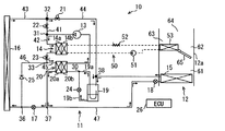
図1に示すように、ヒートポンプサイクル11は、圧縮機13、凝縮器14、蒸発器15、室外器16、暖房用減圧部17、冷房用減圧部18、アキュムレータ19、内部熱交換器20、暖房用高圧側開閉部21、冷房用開閉部22、暖房用低圧側開閉部23、および流量調整部24を備えている。ヒートポンプサイクル11は、これらを配管により接続することによりサイクルが形成されている。
As shown in FIG. 1, the
先ず、配管の構成に関して説明する。圧縮機13の吐出側には、第1分岐部31が設けられている。第1分岐部31は、冷房用開閉部22に接続される第1流路41と、凝縮器14側に接続される第2流路42とに分岐している。冷房用開閉部22の下流側には、第2分岐部32が設けられている。第2分岐部32は、室外器16に接続される第3流路43と、アキュムレータ19に接続される第4流路44とに分岐している。また第4流路44の途中には、暖房用高圧側開閉部21が設けられている。凝縮器14の下流側には、暖房用低圧側開閉部23および第3分岐部33が、この順に設けられている。第3分岐部33は、内部熱交換器20の高圧流路20aに接続される第5流路45と、第6分岐部36に接続される第6流路46とに分岐している。
First, the configuration of the piping will be described. A
室外器16は、蒸発器15の上流側と第7流路47によって接続されている。第7流路47の室外器16側には、前述の第6分岐部36が設けられている。第7流路47の第6分岐部36よりも蒸発器15側には、第7分岐部37が設けられている。第7流路47において、第6分岐部36と第7分岐部37との間には、暖房用減圧部17が設けられている。
The
また第7流路47において、第7分岐部37と蒸発器15との間には、冷房用減圧部18が設けられている。また第6流路46には、逆止弁25が設けられている。逆止弁25は、第6分岐部36から第3分岐部33に向かう冷媒の流れを許容し、第3分岐部33から第6分岐部36への流れを禁止する。内部熱交換器20の高圧流路20aの下流側は、第7分岐部37に接続されている。
In the
蒸発器15の下流側には、第8分岐部38が設けられている。第8分岐部38は、第4流路44の暖房用高圧側開閉部21とアキュムレータ19との間に設けられている。アキュムレータ19の下流側は、内部熱交換器20の低圧流路20bに接続されている。内部熱交換器20の低圧流路20bの下流側は、圧縮機13の吸入側に接続されている。
An
次に、ヒートポンプサイクル11の各部の動作に関して説明する。圧縮機13は、蓄電池である車載バッテリ(図示せず)からの給電によって駆動し、冷媒を高温高圧に圧縮して吐出する電動の圧縮機13であり、回転数制御が可能なように構成されている。圧縮機13は、インバータにより周波数が調整された交流電圧が印加されてそのモータの回転速度が制御され、吐出量が制御される。インバータは、車載バッテリから直流電源の供給を受け、制御装置26によって制御される。
Next, the operation of each part of the
凝縮器14は、冷媒が流れる高温流路14aと、水または自動車用冷却水が流れる水流路14bとを備える。凝縮器14は、暖房時に、圧縮機13から吐出された高温高圧の冷媒が流入する。そして凝縮器14は、高温高圧の冷媒と水とを熱交換して、水を加熱する。水流路14bは、水サイクル50の一部を構成する。水サイクル50には、液送部51、加熱部52および放熱器53が接続されている。水サイクル50は、液送部51によって水が循環する。加熱部52は、循環する水を加熱する。加熱部52は、たとえば電気によって発熱し、凝縮器14による加熱を補助する。放熱器53は、車室内に通じる空気通路61に設けられる。放熱器53は、循環する水と通過する空気とを熱交換して、空気を加熱する。
The
暖房用減圧部17は、暖房時に凝縮器14で冷却された冷媒を減圧する膨張弁である。暖房用減圧部17は、絞り開度が制御可能であり、閉状態にすることができる。暖房用減圧部17は、具体的には、絞り開度を変更可能に構成された弁体と、この弁体の絞り開度を変化させるステッピングモータからなる電動アクチュエータとを有して構成される電気式の可変絞り機構である。
The
冷房用減圧部18は、冷房時に蒸発器15に流入させる冷媒を減圧する膨張弁である。冷房用減圧部18は、絞り開度が制御可能であり、閉状態にすることができる。冷房用減圧部18は、前述の暖房用減圧部17と同様の電気式の可変絞り機構である。
The
室外器16は、車両の車室外に配置されており、室外器用送風機(図示せず)により強制的に送風される外気、または走行時の走行風と冷媒とを熱交換する熱交換器である。室外器16は、暖房時には暖房用減圧部17で減圧された冷媒が流入して外気から吸熱する。また室外器16は、冷房時には圧縮機13によって圧縮された高圧の冷媒が流入して外気へ放熱する。室外器16は、多数のチューブが間隔をあけて設けられている。室外器16に流入した冷媒は、多数のチューブに分岐して流れ、チューブの外部を流れる外気と熱交換する。
The
蒸発器15は、車室内に通じる空気通路61に設けられる。蒸発器15は、放熱器53の上流側に設けられている。蒸発器15は、冷房時、内部を流れる冷媒の吸熱作用によって、通過する空気を冷却する。
The
アキュムレータ19は、冷媒をガス冷媒と液冷媒とに分離する。アキュムレータ19は、図1に示すように、分離したガス冷媒を流出させるガス冷媒流路19aと、分離した液冷媒を流出させる液冷媒流路19bとを備える。ガス冷媒流路19aおよび液冷媒流路19bは、内部熱交換器20の低圧流路20bに接続されている。具体的には、ガス冷媒流路19aおよび液冷媒流路19bは、内部熱交換器20に流入する前に合流部30で合流し、合流部30と内部熱交換器20の低圧流路20bの流入側が接続されている。また液冷媒流路19bには、アキュムレータ19から内部熱交換器20への液冷媒の流量を調整する流量調整部24が設けられている。流量調整部24は、液冷媒の流量が制御装置26によって制御される。
The
内部熱交換器20は、高圧の冷媒が流れる高圧流路20aと低圧の冷媒が流れる低圧流路20bとを有する。内部熱交換器20は、高圧流路20aと低圧流路20bとを流れる冷媒間で熱交換させる。低圧流路20bの上流側は、アキュムレータ19の下流側に接続される。低圧流路20bの下流側は、圧縮機13の吸入側に接続される。また高圧流路20aの上流側は、第5流路45に接続される。高圧流路20aの下流側は、第7分岐部37に接続される。
The
冷房用開閉部22、暖房用高圧側開閉部21および暖房用低圧側開閉部23は、それぞれ設けられた配管を開閉する。各開閉部21〜23は、制御装置26によって開閉状態が制御される。制御装置26は、各開閉部21〜23および各減圧部17,18の開閉状態を制御することによって、冷媒を流す経路を変更する。したがって各開閉部21〜23および各減圧部17,18は、冷媒が流れる経路を変更する流路変更部として機能する。
The cooling opening / closing
次に、空調ユニット12に関して説明する。空調ユニット12は、車室内に空調風を提供するためのユニットである。空調ユニット12は、空調ケース12aを外郭とし、例えば、車室内前方のインストルメントパネルの裏側に設けられている。空調ケース12aは、内部に空気が流れる空気通路61を備え、一方側に空気取入口である外気吸入口および内気吸入口が形成される。通風路の他方側には、車室内に吹き出される空気調節された空調空気が通過するフェイス吹出口、フット吹出口、およびデフ吹出口が形成されている。空調ケース12aは、複数のケース部材からなり、その材質は例えばポリプロピレン等の樹脂成形品である。
Next, the
フェイス吹出口は、車室内の乗員の上半身に向かって吹き出される空調空気が通過する開口である。フット吹出口は、車室内の乗員の足元に吹き出される空調空気が通過する開口である。デフ吹出口は、車両のフロントガラスの内面に吹き出される空調空気が通過する開口である。これらの各吹出口は、それぞれ吹出しダクトを介して車室内空間に接続されており、吹出口の切替えドアによって吹出しモードに対応してそれぞれ開閉される。 The face outlet is an opening through which conditioned air blown toward the upper body of the passenger in the passenger compartment passes. The foot outlet is an opening through which conditioned air blown out to the feet of the passengers in the passenger compartment. The differential outlet is an opening through which conditioned air blown out to the inner surface of the windshield of the vehicle passes. Each of these air outlets is connected to the vehicle interior space via an air outlet duct, and is opened and closed corresponding to the air outlet mode by a switching door of the air outlet.
空調ケース12aは、一方側に、内外気設定ドアを備える内外気切替箱と、その吸込部が外気吸入口と内気吸入口に接続されている空調用送風機と、を備えている。内気吸入口と外気吸入口とは、内外気設定ドアによって、空気取入れモードに対応してその開放、閉鎖が切替え自在、または開放度合いが調整自在に行われる。すなわち、内外気設定ドアは、そのドア本体がサーボモータ等のアクチュエータで角度調整されることによって、外気および内気の少なくとも一方を空気取入口から空調ケース12a内に取り入れることができるようになっている。内外気設定ドアを制御して、内気循環モードと、外気導入モードと、これらの中間である内気循環および外気導入の両方を有する中間モードとを切り替えることができる。
The
空調用送風機の吹出口は、空気通路61に接続されている。空気通路61は、送風空気の上流側から順に、蒸発器15が横断する通路と、蒸発器15の送風空気下流側に配置される冷風通路62および温風通路63と、冷風通路62と温風通路63とを流れてきた空気が混合される空気混合空間部64とを、含む。空調用送風機の下流側に蒸発器15が配置され、蒸発器15よりもさらに下流に放熱器53およびエアミックスドア65が配置されている。
The air outlet of the air conditioning blower is connected to the
蒸発器15は、空調用送風機直後の空気通路61全体を横断するように配置されており、空調用送風機から吹き出された空気の全部が通過するようになっている。温風通路63には放熱器53が配置されており、温風通路63は、エアミックスドア65によって開放および閉鎖されるようになっている。エアミックスドア65は、蒸発器15を通過した空気のうち、放熱器53を通過させる空気の風量を調整する風量調整手段である。蒸発器15を通過した空気は、エアミックスドア65によって、放熱器53を通る空気と放熱器53を迂回する空気とに風量比率が自在に分けられるようになっている。
The
制御装置26は、制御部であって、図1ではECU(Electronic Control Unit)と印している。また制御装置26は、図1では制御のための接続線は省略するが、各運転状態に応じて、ヒートポンプサイクル11を構成する各部品の作動、室外器用送風機の作動、内外気設定ドアの作動およびエアミックスドア65の作動等を制御する。
The
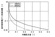
次に、ヒートポンプサイクル11に用いられる冷媒に関して、図2および図3を用いて説明する。本実施形態では、室外器16が蒸発器として作動する際の冷媒の乾き度を下げ、液単相に近い状態で室外器16に流入させることで、室外器16の内部にて均一な冷媒分配を目的としている。このような目的を達成するためには、冷媒のガス体積を減らして液体積を増やす必要があるので、室外器16への流入時の冷媒の乾き度は経験的に0.15以下、好ましくは0.1未満にする必要がある。
Next, the refrigerant | coolant used for the
暖房時に室外器16を蒸発器として作動させる場合、低外気温からの吸熱が必要になるので、通常の冷房時よりもより低温の冷媒が必要となる。たとえば外気温が−20℃の環境下で吸熱させる場合には、室外器16内を流れる冷媒の温度は当然外気温よりも低い必要があり、例えば冷媒にR134aを用いた場合、冷媒温度が約−26.4℃のとき、冷媒圧力は約100kPaとなる。一方、夏季の冷房時などは外気温も高いため、たとえば蒸発器15内の冷媒温度が0.7℃の際、冷媒圧力はおよそ300kPaとなる。冷媒作動圧力が低圧になるほど、図3に示すように、液とガスの密度比は大きくなる。
When the
ヒートポンプ作動環境下で室外器16の冷媒分配の均一化を図るためには、冷媒乾き度はより0に近い領域で作動させる必要がある。図2および図3に示すように、冷媒が低圧になることで、冷媒の密度が低下する。すなわち同一の質量流量のときに体積流量が増加するため、冷媒圧損が大きくなる。
In order to achieve uniform refrigerant distribution in the
暖房時に室外器16が蒸発器として作動する場合、冷媒圧損が性能に大きく影響するため、低圧損化が必要となる。室外器16に流入前に冷媒の乾き度を下げる効果は、冷媒分配の改善に加え、圧損低減による性能向上にも効果的である。たとえば冷媒R134aの100kPaにおける冷媒乾き度0〜0.5における平均密度は約52.3kg/m3であり、同条件の乾き度0.5〜1における平均密度は約7.3kg/m3であり、密度比はおよそ7.3倍にもなる。したがって液冷媒が多くなると、平均密度が高くなるので圧力損失を低減することができる。
When the
次に、ヒートポンプシステム10の作動に関して説明する。制御装置26は、運転モードが冷房運転の場合、エアミックスドア65を温風通路63が閉状態に制御する。また制御装置26は、冷房用開閉部22を開状態に、暖房用高圧側開閉部21、暖房用低圧側開閉部23および暖房用減圧部17を閉状態に制御する。
Next, the operation of the
これによって冷房運転時の冷媒の流れは、図4の矢印で示した流れとなる。すなわち冷房時の冷媒の経路である冷房経路は、圧縮機13、室外器16、内部熱交換器20の高圧流路20a、冷房用減圧部18、蒸発器15、アキュムレータ19、内部熱交換器20の低圧流路20b、圧縮機13の順で冷媒が循環する経路である。
As a result, the refrigerant flow during the cooling operation becomes the flow indicated by the arrows in FIG. In other words, the cooling path, which is the refrigerant path during cooling, includes the
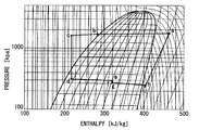
次に、各部の動作とともに冷媒の流れを、図5のモリエル線図と共に説明する。圧縮機13から吐出された高圧ガス冷媒(点a)は、第1流路41および第3流路43を流れ、室外器16に流入する。室外器16に流入した高圧ガス冷媒は、外気に放熱し、凝縮する(点b)。室外器16を流出した液冷媒は、逆止弁25を介して内部熱交換器20の高圧流路20aへ流入する。
Next, the flow of the refrigerant together with the operation of each part will be described with reference to the Mollier diagram of FIG. The high-pressure gas refrigerant (point a) discharged from the
内部熱交換器20の高圧流路20aへ流入した液冷媒は、内部熱交換器20の低圧流路20bを流れる低温の冷媒と熱交換し、さらに過冷却される(点c)。内部熱交換器20を流出した冷媒は、冷房用減圧部18にて低温低圧の二相冷媒に膨張し、蒸発器15へ流入する(点d)。蒸発器15を通過する空気は、液冷媒の蒸発に伴い冷却され、その冷却空気にて車室内を冷房する。
The liquid refrigerant flowing into the high-
蒸発器15を流出した二相冷媒は(点e)、第8分岐部38を通過して、アキュムレータ19へ流入する(点f)。アキュムレータ19にて気液分離された冷媒のうち、ガス冷媒はガス冷媒流路19aを通り、液冷媒は液冷媒流路19bを通り合流部30で合流(点g)する。そして内部熱交換器20の低圧流路20bへ流入し、前述のように室外器16を流出した冷媒と熱交換され、加熱される(点h)。内部熱交換器20を流出したガス冷媒は、圧縮機13に流入する(点i)。
The two-phase refrigerant that has flowed out of the evaporator 15 (point e) passes through the
このように本実施形態では、冷房時に内部熱交換器20を利用することで、蒸発器15内を流れる冷媒の平均乾き度を低減することができる。これにより、蒸発器15内の冷媒圧損を低減することができ、さらに、蒸発器15内に過熱度領域も発生しないため、蒸発器15性能が向上し、システムの効率が改善できる。
Thus, in this embodiment, the average dryness of the refrigerant flowing in the
次に、暖房時の作動に関して説明する。制御装置26は、運転モードが暖房運転の場合、エアミックスドア65を温風通路63に空気が流れる開度に制御する。また制御装置26は、冷房用開閉部22および冷房用減圧部18を閉状態に、暖房用高圧側開閉部21および暖房用低圧側開閉部23を開状態に制御する。
Next, the operation during heating will be described. When the operation mode is the heating operation, the
これによって暖房運転時の冷媒の流れは、図6の矢印で示した流れとなる。すなわち暖房時の冷媒の経路である暖房経路は、圧縮機13、凝縮器14、内部熱交換器20の高圧流路20a、暖房用減圧部17、室外器16、アキュムレータ19、内部熱交換器20の低圧流路20b、圧縮機13の順で冷媒が循環する経路である。
Thereby, the flow of the refrigerant during the heating operation becomes the flow indicated by the arrows in FIG. That is, the heating path, which is the refrigerant path during heating, includes the
次に、各部の動作とともに冷媒の流れを、図7のモリエル線図と共に説明する。圧縮機13から吐出された高圧ガス冷媒(点a)は、第2流路42を流れ、凝縮器14に流入する。凝縮器14に流入した高圧ガス冷媒は、水流路14bを流れる冷却水に放熱し、凝縮する(点b)。凝縮器14を流出した液冷媒は、暖房用低圧側開閉部23を通過して、内部熱交換器20の高圧流路20aへ流入する。
Next, the flow of the refrigerant together with the operation of each part will be described with reference to the Mollier diagram of FIG. The high-pressure gas refrigerant (point a) discharged from the
内部熱交換器20の高圧流路20aへ流入した液冷媒は、内部熱交換器20の低圧流路20bを流れる低温の冷媒と熱交換し、さらに過冷却される(点c)。内部熱交換器20を流出した冷媒は、暖房用減圧部17にて低温低圧二相冷媒に膨張し、室外器16へ流入する(点d)。室外器16を通過する外気により、室外器16の内部を流れる液冷媒を蒸発させ、外気から吸熱する(点e)。
The liquid refrigerant flowing into the high-
室外器16を流出した二相冷媒は、暖房用高圧側開閉部21および第8分岐部38を通過して、アキュムレータ19へ流入する(点f)。アキュムレータ19にて気液分離された冷媒のうち、ガス冷媒はガス冷媒流路19aを通り、液冷媒は液冷媒流路19bを通り合流部30で合流(点g)する。そして内部熱交換器20の低圧流路20bへ流入し、前述のように凝縮器14を流出した冷媒と熱交換され、加熱される(点h)。内部熱交換器20を流出したガス冷媒は、圧縮機13に流入する(点i)。
The two-phase refrigerant that has flowed out of the
このように本実施形態では、凝縮器14を流出後の液冷媒を内部熱交換器20にてさらに過冷却し、室外器16の入口の冷媒乾き度が0近辺になるエンタルピ(点c)まで内部熱交換する。これにより、室外器16の入口の液冷媒体積比率が大きくなるため、室外器16を構成する多数のチューブへの冷媒分配が改善できる。そのため、冷媒パスを例えば1パス化し、チューブが多数配置されていても、冷媒分配の略均一化が図れ、室外器16全体を有効利用することができる。また、室外器16出口の冷媒乾き度は0.6程度の乾き度で出て行くため、室外器16出口近傍での液冷媒の過熱度領域も生じにくくなる。内部熱交換器20による室外器16の冷媒作動乾き度を低乾き度域で作動させることで、冷媒圧損の低減に加え、冷媒の均一分配が図れるため、蒸発性能の向上が期待できる。
As described above, in this embodiment, the liquid refrigerant after flowing out of the
本実施形態のモリエル線図(図7)上に示す作動点と、内部熱交換器20を有さない従来のヒートポンプのモリエル線図(図8)上に示す作動点を比較する。すると、室外器16のエンタルピ差はおよそ同じ値であるため、冷媒流量が同じ場合、室外器16の吸熱量は等しくなる。仮に両システムとも同じ室外器16を用いた場合、従来システムにおいては乾き度およそ0.4で流入し(点d)、乾き度およそ1で流出する(点e)。一方、本実施形態では、乾き度およそ0で流入し(点d)、乾き度およそ0.6で流出する(点e)。
The operating point shown on the Mollier diagram (FIG. 7) of this embodiment and the operating point shown on the Mollier diagram (FIG. 8) of the conventional heat pump which does not have the
この作動域の違いにより冷媒の平均密度が大きく変化する。具体的には、従来システムの作動範囲に比べ、本実施形態の作動領域で使用した場合、平均冷媒密度はおよそ2.7倍の密度となる。すなわち、同じ室外器16を用い、同じエンタルピ差、同じ冷媒質量流量でも、本実施形態の作動域で用いた場合、室外器16で発生する冷媒圧損は異なる結果となる。したがって本実施形態では、室外器16の冷媒圧損を大きく低減できる。
The average density of the refrigerant changes greatly due to the difference in the operating range. Specifically, when used in the operating range of the present embodiment, the average refrigerant density is approximately 2.7 times the operating range of the conventional system. That is, when the same
さらに、従来システムでは室外器16からアキュムレータへと戻る配管部で大きな冷媒圧損が発生するが、本実施形態の場合、乾き度0.6程度で流れるため、配管を流れる冷媒密度が1.7倍程度となり、流速低減し、配管での冷媒圧損も低減が可能となる。
Furthermore, in the conventional system, a large refrigerant pressure loss occurs in the pipe portion returning from the
前述の圧損低減分に収まるような低圧損の内部熱交換器20を用い、さらに、内部熱交換器20の出口と圧縮機13の接続配管を短くすることで、内部熱交換器20を追加した本実施形態でも従来システムより冷媒圧損を低減することが可能となる。したがって低温時の蒸発性能をより向上させることが可能となる。したがって内部熱交換器20は、アキュムレータ19までの配管距離よりも圧縮機13までの配管距離が小さくなるように構成されることが好ましい。換言すると、室外器16の冷媒物性が低乾き度領域で作動することにより、室外器16内の冷媒圧損を低減することができ蒸発性能向上が期待できる。
The
次に、除湿暖房時の作動に関して説明する。制御装置26は、運転モードが除湿暖房運転の場合、エアミックスドア65を温風通路63に空気が流れる開度に制御する。また制御装置26は、冷房用開閉部22を閉状態に、暖房用高圧側開閉部21および暖房用低圧側開閉部23を開状態に制御する。
Next, the operation at the time of dehumidifying heating will be described. When the operation mode is the dehumidifying heating operation, the
これによって除湿暖房運転時の冷媒の流れは、図9の矢印で示した流れとなる。基本となる流れは、前述の暖房運転と同じであるが、その際に、冷房用減圧部18を開き、蒸発器15でも冷媒を蒸発させる点が異なる。これにより蒸発器15にて空気を除湿し、放熱器53にて冷えた空気を加熱し、車室内を暖房させることが可能となる。
As a result, the refrigerant flow during the dehumidifying heating operation is the flow indicated by the arrows in FIG. The basic flow is the same as the heating operation described above, except that the
図9に示す除湿運転時には、図示は省略しているが、アキュムレータ19と蒸発器15の間に圧力調整部として、エバポレータプレッシャレギュレータ(略称EPR)が必要となる。EPRの目的は室外器16と、蒸発器15で異なる蒸発温度をつくることである。蒸発器15では除湿が目的なので、冷媒の温度は0℃くらい、すなわち300kPa程度となるが、室外器16側は外気温によって冷媒温度が決まる。例えば、外気温が−10℃だったら冷媒温度は−15℃とかで冷媒圧力は150kPa程度になる。つまり、アキュムレータ19手前の第8分岐部38の上流側で冷媒圧力を調整するよう、言い換えると蒸発器15に流す冷媒流量をコントロールするために、EPRが用いられる。
Although not shown in the dehumidifying operation shown in FIG. 9, an evaporator pressure regulator (abbreviated as EPR) is required as a pressure adjusting unit between the
また除湿運転の場合、図10および図11に示すように他の冷媒の流れであってもよい。図10に示す冷媒流れでは、制御装置26は、冷房用開閉部22を開状態に、暖房用高圧側開閉部21および暖房用低圧側開閉部23および暖房用減圧部17を閉状態に制御する。また制御装置26は,加熱部52によって循環する水を加熱するように制御する。
Further, in the case of the dehumidifying operation, other refrigerant flows may be used as shown in FIGS. In the refrigerant flow shown in FIG. 10, the
これによって除湿暖房運転時の冷媒の流れは、図10の矢印で示した流れとなる。基本となる流れは、前述の冷房運転と同じであるが、エアミックスドア65の開度が放熱器53を空気が通過するように制御される。これによって冷房運転で蒸発器15によって通過する空気を除湿されるが、通過した空気の温度は低下する。そこで放熱器53を通過させることによって、通過する空気を加熱して、車室内に送風することができる。このような構成の場合には、前述のEPRは不要である。
Thereby, the flow of the refrigerant during the dehumidifying heating operation is the flow indicated by the arrow in FIG. The basic flow is the same as in the above-described cooling operation, but the opening of the
次に、図11に示す冷媒流れでは、制御装置26は、暖房用低圧側開閉部23を開状態に、暖房用高圧側開閉部21、冷房用開閉部22および暖房用減圧部17を閉状態に制御する。
Next, in the refrigerant flow shown in FIG. 11, the
これによって除湿暖房運転時の冷媒の流れは、図10の矢印で示した流れとなる。基本となる流れは、前述の暖房運転と類似しており、室外器16でなく蒸発器15に冷媒を流して、除湿している。これによって暖房運転で蒸発器15によって通過する空気を除湿される。このような構成の場合にも、前述のEPRは不要である。また除湿運転の場合、図10および図11のような冷媒流れを時間で切り替えて運転してもよい。
Thereby, the flow of the refrigerant during the dehumidifying heating operation is the flow indicated by the arrow in FIG. The basic flow is similar to the heating operation described above, and the refrigerant is dehumidified by flowing the refrigerant not through the
次に、アキュムレータ19と内部熱交換器20をつなぐ流量調整部24の制御方法に関して、図7を用いて説明する。制御装置26は、暖房経路のとき、圧縮機13に吸入する前の冷媒物性を、冷媒温度または配管温度と、冷媒圧力を測定することで乾き度を推定し、乾き度が所定の目標値に近づくよう流量調整部24を制御する。
Next, a control method of the flow
具体的には、圧縮機13の吸入冷媒は乾き度1前後、すなわちガス冷媒が好ましい(点i)。この点iを起点とし、目標吹出し温度から圧縮機13の回転数を決める。すると凝縮器14の出口の状態が熱負荷から決まる(点b)。
Specifically, the suction refrigerant of the
次に、凝縮器14の出口のエンタルピと、外気条件と、冷媒流量と、内部熱交換器20の性能から、最大の内部熱交換量ΔHが決まる。したがって圧縮機13吸入前の冷媒の過熱度が確保できなくなる前後。すなわち乾き度およそ1になるまで流量調整部24の開度を制御し、できる限り室外器16入口の冷媒乾き度を下げる。
Next, the maximum internal heat exchange amount ΔH is determined from the enthalpy at the outlet of the
以上説明したように本実施形態のヒートポンプシステム10は、暖房経路では、内部熱交換器20で熱交換することによって、凝縮器14で凝縮された冷媒のエンタルピを下げることができる。これによって室外器16入口の冷媒の乾き度を低くすることができる。室外器16入口の冷媒乾き度を低くできると、流入する液冷媒の体積比が増加し、室外器16内の冷媒分配性を改善することが可能となる。したがって室外器16における熱交換性能を向上することができる。
As described above, the
また冷房経路では、内部熱交換器20で熱交換することによって、室外器16で冷却された冷媒を、アキュムレータ19からの液冷媒によってさらに冷却することができる。その後、内部熱交換器20の高圧流路20aを通過した冷媒は、冷房用減圧部18、蒸発器15に流れる。内部熱交換器20で冷媒はさらに冷却されているので、蒸発器15内を流れる冷媒の平均乾き度を低減することができる。これによって蒸発器15内の冷媒圧損を低減することができ、さらに、蒸発器15内に過熱度領域の発生の抑制になるので、蒸発器15の性能が向上し、システム効率を改善することができる。
In the cooling path, the refrigerant cooled by the
また本実施形態では、アキュムレータ19から内部熱交換器20への液冷媒の流量を調整する流量調整部24が設けられている。流量調整部24が設けられているので、内部熱交換器20における内部熱交換量を制御することができる。これによって室外器16の入口の乾き度が小さくなるように制御することができる。
In the present embodiment, a flow
また本実施形態では、制御装置26は、室外器16の入口の冷媒の乾き度を小さくなるように、例えば0.1未満となるように流量調整部24を制御する。乾き度が0.1未満の領域は、図2に示すように、冷媒の密度が急激に上昇し、液冷媒が多くなる領域である。このように乾き度が0.1未満では、冷媒の大部分が液冷媒であるので、前述のように、室外器16においてより広い領域に冷媒を流すことができる。
Moreover, in this embodiment, the
本実施形態では、室外器16を流出した冷媒は、全て内部熱交換器20の高圧流路20aを通過するように構成されているが、このような構成に限るものではない。たとえば図12に示すように、暖房用減圧部17の絞り開度を制御して、冷媒の一部は内部熱交換器20を通過させずに、蒸発器15へと流れるようにしてもよい。暖房用減圧部17の弁開度を調整することで、内部熱交換器20へ流れる冷媒流量を制御することができるので、内部熱交換量をコントロールすることが可能となり、システム制御性が良好となる。
In the present embodiment, all the refrigerant that has flowed out of the
(第2実施形態)
次に、本発明の第2実施形態に関して、図13を用いて説明する。本実施形態では、アキュムレータ19から内部熱交換器20への液冷媒戻し量を制御する点に特徴を有する。制御装置26は、暖房経路のとき、圧縮機13が吸入する前の冷媒物性を測定して冷媒の乾き度を推定し、乾き度が所定の目標値に近づくよう流量調整部24を制御する。
(Second Embodiment)
Next, a second embodiment of the present invention will be described with reference to FIG. The present embodiment is characterized in that the amount of liquid refrigerant returned from the
冷房時および暖房時それぞれ最適な効率を発揮するために、圧縮機13への吸入冷媒の過熱度を制御する必要がある。そこで本実施形態では、内部熱交換器20の低圧流路20bと圧縮機13との間に感温部70を設けている。
It is necessary to control the degree of superheat of the refrigerant sucked into the
感温部70は、冷媒の温度と圧力とよって過熱度を検知している。この過熱度が予め設定された所定値となるように、流量調整部24は機械的機構によって弁開度を調整して、液冷媒流路19bの冷媒流量を調整している。したがって流量調整部24は、温度作動式である。
The
換言すると、圧縮機13の手前の冷媒温度と冷媒圧力を測定し、その値に基づきアキュムレータ19からの液冷媒戻し量を流量調整部24にて調整している。
In other words, the refrigerant temperature and the refrigerant pressure before the
これによって冷房および暖房の両シーンで最適な吸入冷媒の状態をコントロールすることが可能となり、ヒートポンプシステム10の効率を向上させることができる。暖房時は室外器16の入口の冷媒乾き度を0に近づけたいので、より多くの液冷媒をアキュムレータ19から内部熱交換器20へ流入させ、内部熱交換量が最大となるように制御する。一方、冷房時は、圧縮機13が吸入する冷媒が適度な過熱度をもつようアキュムレータ19からの液冷媒戻し量を制御することでサイクルのCOPを向上させる。
As a result, it is possible to control the optimum state of the intake refrigerant in both the cooling and heating scenes, and the efficiency of the
アキュムレータ19からの液冷媒戻し量の制御方法は、エキパンなどによる自己制御であってもよい。また温度および圧力の計測値または予測値に基づいて流量調整部24の開度を電気的に制御する方法であってもよい。
The method for controlling the return amount of the liquid refrigerant from the
(第3実施形態)
次に、本発明の第3実施形態に関して、図14〜図16を用いて説明する。本実施形態では、第1実施形態とアキュムレータ19の下流側の配管の接続位置が異なり、第2実施形態とは感温部70が設けられる位置が異なる。
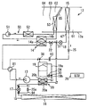
(Third embodiment)
Next, a third embodiment of the present invention will be described with reference to FIGS. In the present embodiment, the connection position of the piping on the downstream side of the first embodiment and the
アキュムレータ19のガス冷媒流路19aは、内部熱交換器20の低圧流路20bの上流側に接続されずに、内部熱交換器20の下流側、すなわち内部熱交換器20と圧縮機13との間の第2合流部30aに接続されている。したがってアキュムレータ19のガス冷媒は、直接、圧縮機13に吸入される。液冷媒流路19bは、内部熱交換器20の低圧流路20bに接続されている。したがってアキュムレータ19の液冷媒は、内部熱交換器20を経由して圧縮機13に戻される。感温部70は、第2合流部30aの下流側に設けられている。
The gas
次に、暖房時の作動に関して説明する。暖房運転時の冷媒の流れは、前述の第1実施形態と同様であり、図14の矢印で示した流れとなる。次に、各部の動作とともに冷媒の流れを、図15のモリエル線図と共に説明する。圧縮機13から吐出された高圧ガス冷媒(点a)は、凝縮器14で凝縮する(点b)。凝縮器14を流出した液冷媒は、暖房用低圧側開閉部23を通過して、内部熱交換器20の高圧流路20aへ流入し、内部熱交換器20の低圧流路20bを流れる低温の液冷媒と熱交換し、さらに過冷却される(点c)。ここでは、アキュムレータ19によって分離された液冷媒のみが低圧流路20bに流入するので、第1実施形態よりも熱交換量が少なく、高圧流路20a側の温度低下は小さい。
Next, the operation during heating will be described. The flow of the refrigerant during the heating operation is the same as that in the first embodiment described above, and is the flow indicated by the arrows in FIG. Next, the flow of the refrigerant together with the operation of each part will be described with reference to the Mollier diagram of FIG. The high-pressure gas refrigerant (point a) discharged from the
内部熱交換器20を流出した冷媒は、暖房用減圧部17にて低温低圧二相冷媒に膨張し、室外器16へ流入(点d)し、室外器16で蒸発させ外気から吸熱する(点e)。室外器16を流出した二相冷媒は、アキュムレータ19へ流入し、アキュムレータ19を流出した液冷媒は、内部熱交換器20の低圧流路20bへ流入し(点f)、前述のように凝縮器14を流出した冷媒と熱交換され、加熱される(点g)。またアキュムレータ19を流出したガス媒は(点h)、第2合流部30aで内部熱交換器20の低圧流路20bを流下した液冷媒と合流し、圧縮に吸入される(点i)。
The refrigerant that has flowed out of the
このようにアキュムレータ19からの液冷媒流路19bとガス冷媒流路19aとを分離することで、アキュムレータ19から圧縮機13へ至る流路の冷媒圧損を低減することができ、暖房性能向上が図れる。
Thus, by separating the liquid
本実施形態では、流量調整部24は、液冷媒流路19bに設けられているが、内部熱交換器20の低圧流路20bと第2合流部30aとの間に設けてもよい。このような場所に設けても、内部熱交換器20の低圧流路20bを流れる液冷媒の流量を調節することができる。
In the present embodiment, the flow
また本実施形態では、感温部70と流量調整部24とが別体に構成されているが、別体に限るものではない。たとえば図16に示すように、流量調整部243を出入口一体型で構成してもよい。図16に示すように、流量調整部243は、内部熱交換器20の低圧流路20bの流入側および流出側に跨がって設けられる。流量調整部243は、ボックス型の流量調整バルブであり、低圧流路20bの下流側の冷媒の圧力と温度を内部で検知している。この過熱度が予め設定された所定値となるように、流量調整部243は機械的機構によって弁開度を調整している。このような構成であっても、感温部70が別体の構成と同様の作用および効果を奏することができる。
Moreover, in this embodiment, although the
(第4実施形態)
次に、本発明の第4実施形態に関して、図17〜図21を用いて説明する。本実施形態では、第3実施形態と類似しており、第6分岐部36に接続される第6流路46の接続先が第3実施形態とは異なる。したがってアキュムレータ19の下流側の構成および感温部70の構成は、第3実施形態と同様である。第6流路46は、第6分岐部36と第2流路42の第9分岐部39とを接続する。第1分岐部31と第9分岐部39との間には、暖房用低圧側開閉部23が配置されている。
(Fourth embodiment)
Next, a fourth embodiment of the present invention will be described with reference to FIGS. This embodiment is similar to the third embodiment, and the connection destination of the
冷房運転時の冷媒の流れは、図17の矢印で示した流れとなる。したがって冷房時、室外器16と内部熱交換器20の間に凝縮器14を通る構成である。したがって室外器16で凝縮されて流出した液冷媒は、逆止弁25を介して、凝縮器14に流入する。凝縮器14に流入した液冷媒は、水流路14bを流れる冷却水に放熱し、さらに凝縮する。次に、内部熱交換器20の高圧流路20aへ流入した液冷媒は、内部熱交換器20の低圧流路20bを流れる低温の冷媒と熱交換し、さらに過冷却される。
The flow of the refrigerant during the cooling operation is the flow indicated by the arrows in FIG. Therefore, the
これによって春および秋などの中間期における熱負荷は低いが除湿が必要な状況においては、室外器16と凝縮器14で冷媒を凝縮させ、凝縮器14の放熱により加熱された熱を室内の暖房に利用することができる。これによって除湿後の空気を加熱するために外部の熱源を使う必要がなくなり、効率的な運転が可能となる。
As a result, in a situation where the heat load in the intermediate period such as spring and autumn is low but dehumidification is necessary, the refrigerant is condensed by the
次に、短時間除霜に関して、図18〜図20を用いて説明する。除霜制御のため、冷媒状態を検出するセンサが図18には示されている。吸入側の冷媒圧力は、アキュムレータ19の下流側に設置される圧力センサ90によって検出される。また吸入側の冷媒温度は、蒸発器15の下流側に設定される温度センサ91によって検出される。さらに圧縮機13から吐出された冷媒の冷媒圧力および温度は、圧縮機13の吐出側に設置される冷媒センサ92によって検出される。
Next, short-time defrosting will be described with reference to FIGS. FIG. 18 shows a sensor for detecting the refrigerant state for defrost control. The refrigerant pressure on the suction side is detected by a
暖房時、室外器16の表面が着霜していくと、徐々に室外器16の蒸発性能が低下していく。そのため、圧縮機13の回転数を上昇させ、必要性能の維持を図る。着霜が進行していくと、図19に示すように吸入側の冷媒圧力が低下していく。外気温と吸入側の冷媒圧力から着霜判定し、外気温に対し、所定の圧力以下となる場合において、除霜運転に切り替える。
When the surface of the
除霜時の冷媒経路は、冷房時の冷媒経路と同様である。すなわち除霜時の除霜経路は、圧縮機13→室外器16→凝縮器14→内部熱交換器20の高圧流路20a→冷房用減圧部18→蒸発器15→アキュムレータ19→内部熱交換器20の低圧流路20b→圧縮機13の順で接続されている。暖房時に室外器16が着霜して暖房性能が低下した際には、冷媒流路を図18の除霜経路に切り替える。これによって圧縮機13からの高圧冷媒の熱を室外器16に与え除霜することができる。室外器16を流出後の冷媒は、前述のように凝縮器14に流入する。すると、冷媒は、凝縮器14側から熱をもらい、凝縮器14内で蒸発する。凝縮器14を流出後の冷媒は、前述のように内部熱交換器20の高圧流路20a、冷房用減圧部18、蒸発器15、アキュムレータ19、内部熱交換器20の低圧流路20b、圧縮機13の順で循環する。
The refrigerant path at the time of defrosting is the same as the refrigerant path at the time of cooling. That is, the defrosting path at the time of defrosting is: compressor 13-> outdoor unit 16-> condenser 14-> high-
これによって圧縮機13の熱に加え、凝縮器14の熱を利用して室外器16を除霜することができるので、短時間で除霜のための大きな熱を出すことができ、短時間除霜が可能となる。短時間除霜の際、加熱部52によって除霜で消費される熱量を補うよう加熱することで、水温低下を防止できる。したがって除霜後すぐに暖房、あるいは、除霜運転しながら暖房運転を維持することも可能となる。
As a result, the
また図20に示すように、除霜運転初期においては、室外器16の表面は霜がついているため、圧縮機13の吐出側に設置される冷媒センサ92の圧力および温度ともに、あまり変化しない。制御装置26は、除霜経路による冷媒の循環および循環停止を、圧縮機13の吸入側の冷媒圧力および外気温を用いて判断する。具体的には、除霜が完了すると、顕熱変化のみとなるため、室外器16の温度は加熱に応じて上昇していくため、吐出側の圧力または温度は急激に上昇していく。除霜完了の推定方法としては、冷媒圧力または冷媒温度が変曲点を超える状態を、変化率または所定の圧力および温度から推定し、制御すると良い。
As shown in FIG. 20, in the initial stage of the defrosting operation, the surface of the
本実施形態では、室外器16を流出した冷媒は、全て内部熱交換器20の高圧流路20aを通過するように構成されているが、このような構成に限るものではない。たとえば図21に示すように、暖房用減圧部17の絞り開度を制御して、冷媒の一部は内部熱交換器20を通過させずに、蒸発器15へと流れるようにしてもよい。暖房用減圧部17の弁開度を調整することで、内部熱交換器20へ流れる冷媒流量を制御することができるので、内部熱交換量をコントロールすることが可能となり、システム制御性が良好となる。
In the present embodiment, all the refrigerant that has flowed out of the
(第5実施形態)
次に、本発明の第5実施形態に関して、図22を用いて説明する。本実施形態では、第3実施形態と類似しており、凝縮器14が空気通路61に配置されている点が第3実施形態とは異なる。凝縮器14は、車室内に通じる空気通路61に設けられる。凝縮器14は、蒸発器15の下流側に設けられている。凝縮器14は、暖房時、内部を流れる冷媒の放熱作用によって、通過する空気を加熱する。
(Fifth embodiment)
Next, a fifth embodiment of the present invention will be described with reference to FIG. This embodiment is similar to the third embodiment, and differs from the third embodiment in that the
このように水サイクル50を有しない構成であっても、凝縮器14を空気通路61に配置することによって直接、空気を加熱することができる。したがって構成を簡略化することができる。
Thus, even if it is the structure which does not have the
(第6実施形態)
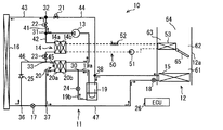
次に、本発明の第6実施形態に関して、図23〜図25を用いて説明する。本実施形態では、第1実施形態と類似しており、暖房用低圧側開閉部23の位置と、アキュムレータ19と内部熱交換器20との接続が異なる。暖房用低圧側開閉部23は、凝縮器14の下流側ではなく、凝縮器14の上流側であった第2流路42に設けられる。アキュムレータ19は、第1実施形態に対して、内部熱交換器20との順序が逆転している。
(Sixth embodiment)
Next, a sixth embodiment of the present invention will be described with reference to FIGS. This embodiment is similar to the first embodiment, and the position of the heating low-pressure side opening / closing
まず、暖房時の作動に関して説明する。制御装置26は、運転モードが暖房運転の場合、エアミックスドア65を温風通路63に空気が流れる開度に制御する。また制御装置26は、冷房用開閉部22および冷房用減圧部18を閉状態に、暖房用高圧側開閉部21および暖房用低圧側開閉部23を開状態に制御する。
First, the operation during heating will be described. When the operation mode is the heating operation, the
これによって暖房運転時の冷媒の流れは、図23の矢印で示した流れとなる。すなわち暖房時の冷媒の経路である暖房経路は、圧縮機13、凝縮器14、内部熱交換器20の高圧流路20a、暖房用減圧部17、室外器16、内部熱交換器20の低圧流路20b、アキュムレータ19、圧縮機13の順で冷媒が循環する経路である。
Thereby, the flow of the refrigerant during the heating operation becomes the flow indicated by the arrow in FIG. That is, the heating path, which is the refrigerant path during heating, includes the
このような流れによって、圧縮機13から凝縮器14に流れた冷媒の熱は、凝縮器14から水サイクル50を介して放熱器53に熱輸送され、送風空気によって車室内を暖房する。凝縮器14を流出した冷媒は、次に内部熱交換器20に流入し、内部熱交換器20にてサブクールを取る。内部熱交換器20を流出した冷媒は、暖房用減圧部17で減圧したあと、室外器16へ流入し、蒸発器として作動する室外器16にて外気から吸熱し、室外器16を流出する。室外器16を流出後の冷媒は、内部熱交換器20の低圧流路20bへ流入し、凝縮器14の出口の冷媒から吸熱し、アキュムレータ19に流入する。アキュムレータ19の流出部は基本的にはガス冷媒のみが流出するために、液面よりも上部に流出口が設けられている配管構造となっているが、圧縮機へ潤滑油を必要最低限戻すために少量の液冷媒が戻るオイル戻し穴が流出部配管の下部に設けられている。内部熱交換器20により、室外器16の出入口における冷媒乾き度は低乾き度となるため、室外器16の冷媒分配性が改善され、外気から多くの熱を吸熱することができるため、サイクル性能向上に繋がる。この構成とすると、圧縮機13の入口の冷媒物性は、アキュムレータ19に設けられたオイル戻し穴の径と冷媒流量によって決まるため簡単な制御で暖房性能向上させることができる。
With such a flow, the heat of the refrigerant flowing from the
次に、冷房時の作動に関して説明する。制御装置26は、運転モードが冷房運転の場合、エアミックスドア65を温風通路63が閉状態に制御する。また制御装置26は、冷房用開閉部22を開状態に、暖房用高圧側開閉部21、暖房用低圧側開閉部23および暖房用減圧部17を閉状態に制御する。
Next, the operation during cooling will be described. When the operation mode is the cooling operation, the
これによって冷房運転時の冷媒の流れは、図24の矢印で示した流れとなる。すなわち冷房時の冷媒の経路である冷房経路は、圧縮機13、室外器16、内部熱交換器20の高圧流路20a、冷房用減圧部18、蒸発器15、内部熱交換器20の低圧流路20b、アキュムレータ19、圧縮機13の順で冷媒が循環する経路である。
As a result, the refrigerant flow during the cooling operation becomes the flow indicated by the arrows in FIG. In other words, the cooling path, which is the refrigerant path during cooling, includes the
このような流れによって、内部熱交換器20での内部熱交換により、蒸発器15内の作動乾き度を低乾き度側で作動させることができるので、低圧損化による蒸発器15の性能向上に伴うサイクル効率改善が期待できる。
With such a flow, the operating dryness in the
次に、除湿暖房時の作動に関して説明する。制御装置26は、運転モードが除湿暖房運転の場合、エアミックスドア65を温風通路63に空気が流れる開度に制御する。また制御装置26は、冷房用開閉部22を閉状態に、暖房用高圧側開閉部21および暖房用低圧側開閉部23を開状態に制御する。さらに制御装置26は、冷房用減圧部18の開度を制御し、蒸発器15にも冷媒が流れるように制御する。
Next, the operation at the time of dehumidifying heating will be described. When the operation mode is the dehumidifying heating operation, the
これによって除湿暖房時は、内部熱交換器20を流出後に冷媒の流れが第7分岐部37で分岐し、一方は室外器16に、他方は蒸発器15へと流れる。両経路とも途中に減圧手段として、暖房用減圧部17および冷房用減圧部18があり、そこで減圧されて室外器16側では吸熱、蒸発器15側では除湿が行われる。蒸発器15下流側に圧力調整手段93を設けることで、蒸発器15と室外器16の冷媒流量と冷媒圧力を独立して制御することが可能となる。これによって必要除湿性能よりも必要暖房性能が大きい条件にて、蒸発器15を冷やし過ぎることなく、暖房性能を向上させることができる。
As a result, during dehumidifying heating, after flowing out of the
また、内部熱交換器20流出後に分岐することで、蒸発器15の冷媒作動乾き度も低乾き度側へシフトするため、低冷媒流量でも良好な冷媒性を得ることができ、蒸発器15出口側の過熱度領域も抑制できるため、フロストの抑制できる効果が期待できる。
Further, branching after the outflow of the
(第7実施形態)
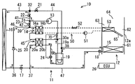
次に、本発明の第7実施形態に関して、図26〜図31を用いて説明する。本実施形態では、四方弁81を用いてヒートポンプサイクル11を構成している点に特徴を有する。図26に示すように、ヒートポンプサイクル11は、圧縮機13、凝縮器14、蒸発器15、室外器16、暖房用減圧部17、冷房用減圧部18、アキュムレータ19、内部熱交換器20、冷房用開閉部22、四方弁81および流量調整部24を備えている。ヒートポンプサイクル11は、これらを配管により接続することによりサイクルが形成されている。
(Seventh embodiment)
Next, a seventh embodiment of the present invention will be described with reference to FIGS. The present embodiment is characterized in that the
先ず、配管の構成に関して説明する。圧縮機13の吐出側には、四方弁81が設けられている。四方弁81は、圧縮機13の吐出側、凝縮器14、アキュムレータ19および室外器16に接続されている。四方弁81は、圧縮機13の吐出側と凝縮器14とを接続し、アキュムレータ19と室外器16とを接続した第1状態と、圧縮機13の吐出側と室外器16とを接続し、アキュムレータ19と凝縮器14とを接続した第2状態とを切替可能に構成されている。
First, the configuration of the piping will be described. A four-
凝縮器14の四方弁81とは反対側には、蒸発器15が設けられている。そして凝縮器14と蒸発器15との間には、冷房用開閉部22、第7分岐部37および冷房用減圧部18がこの順に設けられている。
An
また蒸発器15は、第8分岐部38に接続されている。そして蒸発器15と第8分岐部38との間には、逆止弁25および圧力調整手段93がこの順に設けられている。逆止弁25は、凝縮器14から第8分岐部38に向かう冷媒の流れを許容し、第8分岐部38から蒸発器15への流れを禁止する。
The
内部熱交換器20の高圧流路20aの下流側は、第7分岐部37に接続されている。第8分岐部38は、四方弁81とアキュムレータ19との間に設けられている。アキュムレータ19の下流側は、内部熱交換器20の低圧流路20bに接続されている。内部熱交換器20の低圧流路20bの下流側は、圧縮機13の吸入側に接続されている。
A downstream side of the high-
室外器16と内部熱交換器20の高圧流路20aとの間には、暖房用減圧部17が設けられる。また室外器16と内部熱交換器20の高圧流路20aとの間には、暖房用減圧部17を迂回するバイパス流路94が設けられる。バイパス流路94には、暖房用逆止弁25aが設けられる。暖房用逆止弁25aは、バイパス流路94において室外器16から内部熱交換器20への流れを許容し、逆の流れを禁止する。
A
次に、ヒートポンプシステム10の作動に関して説明する。制御装置26は、運転モードが冷房運転の場合、エアミックスドア65を温風通路63が閉状態に制御する。また制御装置26は、冷房用開閉部22を閉状態に、および暖房用減圧部17を閉状態に制御する。また制御装置26は、冷房用減圧部18の開度を制御し、四方弁81を第2状態に制御する。
Next, the operation of the
これによって冷房運転時の冷媒の流れは、図26の矢印で示した流れとなる。すなわち冷房時の冷媒の経路である冷房経路は、圧縮機13、四方弁81、室外器16、暖房用逆止弁25a、内部熱交換器20の高圧流路20a、冷房用減圧部18、蒸発器15、アキュムレータ19、内部熱交換器20の低圧流路20b、圧縮機13の順で冷媒が循環する経路である。これによって前述の第1実施形態と同様の作用および効果を奏することができる。
As a result, the refrigerant flow during the cooling operation becomes the flow indicated by the arrows in FIG. That is, the cooling path, which is the refrigerant path during cooling, includes the
次に、暖房時の作動に関して説明する。制御装置26は、運転モードが暖房運転の場合、エアミックスドア65を温風通路63が開状態に制御し、液送部51および加熱部52を駆動する。また制御装置26は、冷房用開閉部22を開状態に、および冷房用減圧部18を閉状態に制御する。また制御装置26は、暖房用減圧部17の開度を制御し、四方弁81を第1状態に制御する。
Next, the operation during heating will be described. When the operation mode is the heating operation, the
これによって暖房運転時の冷媒の流れは、図27の矢印で示した流れとなる。すなわち暖房時の冷媒の経路である暖房経路は、圧縮機13、四方弁81、凝縮器14、冷房用開閉部22、内部熱交換器20の高圧流路20a、暖房用減圧部17、室外器16、アキュムレータ19、内部熱交換器20の低圧流路20b、圧縮機13の順で冷媒が循環する経路である。これによって前述の第1実施形態と同様の作用および効果を奏することができる。
Thereby, the flow of the refrigerant during the heating operation becomes the flow indicated by the arrow in FIG. That is, the heating path, which is the refrigerant path during heating, includes the
次に、除霜時の作動に関して説明する。制御装置26は、運転モードが除霜運転の場合、液送部51および加熱部52を駆動する。また制御装置26は、冷房用開閉部22を開状態に、冷房用減圧部18および暖房用減圧部17を閉状態に制御する。また制御装置26は、四方弁81を第2状態に制御する。
Next, the operation at the time of defrosting will be described. The
これによって除霜運転時の冷媒の流れは、図28の矢印で示した流れとなる。すなわち除霜時の冷媒の経路である除霜経路は、圧縮機13、四方弁81、室外器16、暖房用逆止弁25a、内部熱交換器20の高圧流路20a、冷房用開閉部22、凝縮器14、アキュムレータ19、内部熱交換器20の低圧流路20b、圧縮機13の順で冷媒が循環する経路である。
As a result, the refrigerant flow during the defrosting operation is the flow indicated by the arrows in FIG. That is, the defrosting path, which is the refrigerant path during defrosting, includes the
したがって蒸発器15を通過しないため、経路の短縮化が図れ、冷媒流量を大きくすることができ、除霜時間の短縮化が図れる。また凝縮器14は、凝縮の機能がメインのため、通常流路が徐々に狭くなるように設計することが望ましい。これに対し、除霜時は凝縮器14から熱を吸熱するため、除霜時に限っては蒸発器として機能させる。凝縮器14を蒸発器として機能させるためには、通常の凝縮器14とは逆で、流路が徐々に広くなることが圧損の観点から望ましい。そのため、本実施形態では、凝縮器14が逆流する構成として、除霜時に逆流しの構成とすることで凝縮器14の冷媒圧損低減が可能で、冷媒流量をよりたくさん流すことができ、短時間で除霜が可能となる。
Therefore, since it does not pass through the
次に、除湿暖房時の作動に関して説明する。制御装置26は、運転モードが除湿暖房運転の場合、液送部51および加熱部52を駆動する。また制御装置26は、冷房用開閉部22を開状態にし、冷房用減圧部18および暖房用減圧部17の開度を制御する。また制御装置26は、四方弁81を第1状態に制御する。
Next, the operation at the time of dehumidifying heating will be described. The
これによって除湿暖房運転時の冷媒の流れは、図29の矢印で示した流れとなる。基本となる流れは、前述の暖房運転と同じであるが、その際に、冷房用減圧部18を開き、蒸発器15でも冷媒を蒸発させる点が異なる。これにより蒸発器15にて空気を除湿し、放熱器53にて冷えた空気を加熱し、車室内を暖房させることが可能となる。
As a result, the refrigerant flow during the dehumidifying heating operation is the flow indicated by the arrows in FIG. The basic flow is the same as the heating operation described above, except that the
次に、高外気温下での除湿暖房時の作動に関して説明する。制御装置26は、運転モードが高外気温下での除湿暖房運転の場合、液送部51および加熱部52を駆動する。また制御装置26は、冷房用開閉部22および暖房用減圧部17を閉状態に制御し、冷房用減圧部18の開度を制御する。また制御装置26は、四方弁81を第2状態に制御する。
Next, the operation at the time of dehumidifying heating under high outside air temperature will be described. The
これによって高外気温下での除湿暖房運転時の冷媒の流れは、図30の矢印で示した流れとなる。すなわち除湿暖房経路は、圧縮機13、四方弁81、室外器16、暖房用逆止弁25a、内部熱交換器20の高圧流路20a、蒸発器15、アキュムレータ19、内部熱交換器20の低圧流路20b、圧縮機13の順で冷媒が循環する経路である。このように高外気温下では、冷房運転をベースにして除湿し、水サイクル50で暖房に必要な温度を補っている。
Thereby, the flow of the refrigerant during the dehumidifying and heating operation under the high outside air temperature becomes the flow shown by the arrow in FIG. That is, the dehumidifying heating path includes the
次に、室外器16が着霜や着雪等で閉塞し、吸熱ができないような不作動時の暖房作動に関して説明する。制御装置26は、室外器16が不作動の場合に、運転モードが暖房運転の場合、液送部51および加熱部52を駆動する。また制御装置26は、冷房用開閉部22を開状態に、暖房用減圧部17を閉状態に制御し、冷房用減圧部18の開度を制御する。また制御装置26は、四方弁81を第1状態に制御する。
Next, the heating operation at the time of non-operation in which the
これによって室外器16が不作動時の暖房運転時の冷媒の流れは、図31の矢印で示した流れとなる。すなわち冷媒経路は、圧縮機13、四方弁81、冷房用減圧部18、蒸発器15、アキュムレータ19、内部熱交換器20の低圧流路20b、圧縮機13の順で冷媒が循環する経路である。
As a result, the flow of the refrigerant during the heating operation when the
室外器16から吸熱できない条件下、たとえば、室外器16が雪で閉塞、あるいは極低温で外気からの吸熱が難しい場合においては、室内から吸熱する。これにより、外気からの吸熱はできないが、圧縮機13の熱と、加熱部52の熱で高い暖房性能をつくりだせる。
Under conditions where the
(第8実施形態)
次に、本発明の第8実施形態に関して、図32〜図37を用いて説明する。本実施形態は、前述の第7実施形態と類似しており、四方弁81に換えてバルブユニット82を用いてヒートポンプサイクル11を構成している点に特徴を有する。
(Eighth embodiment)
Next, an eighth embodiment of the present invention will be described with reference to FIGS. This embodiment is similar to the seventh embodiment described above, and is characterized in that the
バルブユニット82は、圧縮機13の吐出側に設けられている。バルブユニット82は、圧縮機13の吐出側、凝縮器14、アキュムレータ19および室外器16に接続されている。バルブユニット82は、環状の環状配管83に2つの三方弁として第1三方弁84および第2三方弁85が設けられている。第1三方弁84は、環状配管83と凝縮器14とを接続する部分に設けられる。第2三方弁85は、環状配管83と室外器16とを接続する部分に設けられる。環状配管83における時計回りに第2三方弁85と第1三方弁84との間には、圧縮機13の吐出側が接続される。環状配管83における時計回りに第1三方弁84と第2三方弁85との間には、アキュムレータ19が接続される。
The
また図32に示すように、室外器16と内部熱交換器20との間ではバイパス流路94は用いず、暖房用減圧部17が設けられる。暖房用減圧部17は、逆流することも可能に構成される。
Further, as shown in FIG. 32, the
またバルブユニット82と第8分岐部38との間には、暖房用逆止弁25aが設けられる。暖房用逆止弁25aは、バルブユニット82から第8分岐部38へ向かう流れを許容し、逆の流れを禁止する。また蒸発器15と第8分岐部38との間に設けられる逆止弁25と圧力調整手段93との位置関係が、第7実施形態とは逆になっている。
A
次に、ヒートポンプシステム10の作動に関して説明する。制御装置26は、運転モードが冷房運転の場合、エアミックスドア65を温風通路63が閉状態に制御する。また制御装置26は、冷房用開閉部22を閉状態に、および暖房用減圧部17を開状態に制御し、冷房用減圧部18の開度を制御する。また制御装置26は、バルブユニット82に対して、第1三方弁84を閉状態に、第2三方弁85を圧縮機13と室外器16とを接続するように制御する。
Next, the operation of the
これによって冷房運転時の冷媒の流れは、図32の矢印で示した流れとなる。すなわち冷房時の冷媒の経路である冷房経路は、圧縮機13、バルブユニット82、室外器16、暖房用減圧部17、内部熱交換器20の高圧流路20a、冷房用減圧部18、蒸発器15、アキュムレータ19、内部熱交換器20の低圧流路20b、圧縮機13の順で冷媒が循環する経路である。これによって前述の第7実施形態と同様の作用および効果を奏することができる。
As a result, the refrigerant flow during the cooling operation becomes the flow indicated by the arrows in FIG. That is, the cooling path, which is the refrigerant path during cooling, includes the
次に、外気がおよそ−10度以上の場合の暖房時の作動に関して説明する。制御装置26は、運転モードが暖房運転の場合、エアミックスドア65を温風通路63が開状態に制御し、液送部51および加熱部52を駆動する。また制御装置26は、冷房用開閉部22を開状態にし、暖房用減圧部17の開度を制御し、冷房用減圧部18を閉状態に制御する。また制御装置26は、バルブユニット82に対して、第1三方弁84を圧縮機13と凝縮器14とを接続するように制御し、第2三方弁85をアキュムレータ19と室外器16とを接続するように制御する。
Next, the operation at the time of heating when the outside air is approximately −10 degrees or more will be described. When the operation mode is the heating operation, the
これによって暖房運転時の冷媒の流れは、図33の矢印で示した流れとなる。すなわち暖房時の冷媒の経路である暖房経路は、圧縮機13、バルブユニット82、凝縮器14、冷房用開閉部22、内部熱交換器20の高圧流路20a、暖房用減圧部17、室外器16、アキュムレータ19、内部熱交換器20の低圧流路20b、圧縮機13の順で冷媒が循環する第1暖房経路である。これによって前述の第7実施形態と同様の作用および効果を奏することができる。
Thereby, the flow of the refrigerant during the heating operation becomes the flow indicated by the arrow in FIG. That is, the heating path, which is the refrigerant path during heating, includes the
次に、外気がおよそ−10度未満の場合の暖房時の作動に関して説明する。制御装置26は、運転モードが暖房運転の場合、エアミックスドア65を温風通路63が開状態に制御し、液送部51および加熱部52を駆動する。また制御装置26は、冷房用開閉部22を開状態にし、暖房用減圧部17の開度を制御し、冷房用減圧部18も開状態に制御する。また制御装置26は、バルブユニット82に対して、第1三方弁84を圧縮機13と凝縮器14とを接続するように制御し、第2三方弁85を閉状態に制御する。
Next, the operation at the time of heating when the outside air is less than about −10 degrees will be described. When the operation mode is the heating operation, the
これによって冷媒の流れは、図34の矢印で示した流れとなる。すなわち冷媒経路は、圧縮機13、バルブユニット82、凝縮器14、冷房用開閉部22、冷房用減圧部18、蒸発器15、アキュムレータ19、内部熱交換器20の低圧流路20b、圧縮機13の順で冷媒が循環する第2暖房経路である。これによって外気低温で室外器16から吸熱できない場合においては、室内から吸熱でき、前述の第7実施形態と同様の作用および効果を奏することができる。
As a result, the refrigerant flows as shown by the arrows in FIG. That is, the refrigerant path includes the
次に、除湿暖房時の作動に関して説明する。制御装置26は、運転モードが除湿暖房運転の場合、液送部51および加熱部52を駆動する。また制御装置26は、冷房用開閉部22を開状態にし、冷房用減圧部18および暖房用減圧部17の開度を制御する。また制御装置26は、バルブユニット82に対して、第1三方弁84を圧縮機13と凝縮器14とを接続するように制御し、第2三方弁85をアキュムレータ19と室外器16とを接続するように制御する。
Next, the operation at the time of dehumidifying heating will be described. The
これによって除湿暖房運転時の冷媒の流れは、図35の矢印で示した流れとなる。基本となる流れは、前述の暖房運転と同じであるが、その際に、冷房用減圧部18を開き、圧縮機13の下流で分岐して室外器16ではなく凝縮器14を経て蒸発器15に流れる経路を含む。このような第1除湿暖房経路では、蒸発器15でも冷媒を蒸発させる点が異なる。これにより前述の第7実施形態と同様に、蒸発器15にて空気を除湿し、放熱器53にて冷えた空気を加熱し、車室内を暖房させることが可能となる。
As a result, the refrigerant flow during the dehumidifying heating operation is the flow indicated by the arrows in FIG. The basic flow is the same as that of the heating operation described above, but at this time, the
次に、高外気温下での除湿暖房時の作動に関して説明する。制御装置26は、運転モードがたとえば外気15度以上の高外気温下での除湿暖房運転の場合、加熱部52を駆動することなく、液送部51を駆動する。また制御装置26は、冷房用開閉部22を閉状態に制御し、暖房用減圧部17を開状態に制御し、冷房用減圧部18の開度を制御する。また制御装置26は、バルブユニット82に対して、第1三方弁84を圧縮機13と凝縮器14とを接続するように制御し、第2三方弁85を圧縮機13と室外器16とを接続するように制御する。換言すると、制御装置26は、圧縮機13から吐出された冷媒を、凝縮器14と室外器16とに分配するように制御する。
Next, the operation at the time of dehumidifying heating under high outside air temperature will be described. The
これによって高外気温下での除湿暖房運転時の冷媒の流れは、図36の矢印で示した流れとなる。すなわち冷媒経路は、圧縮機13、バルブユニット82、室外器16、暖房用減圧部17、内部熱交換器20の高圧流路20a、蒸発器15、アキュムレータ19、内部熱交換器20の低圧流路20b、圧縮機13の順で冷媒が循環する第2除湿暖房経路である。また第2除湿暖房経路では、バルブユニット82で分配された冷媒は、凝縮器14、冷房用開閉部22を通過し、第7分岐部37で合流する。
As a result, the flow of the refrigerant during the dehumidifying and heating operation under a high outside air temperature is the flow shown by the arrow in FIG. That is, the refrigerant path includes the
高外気温で必要暖房性能が低く、除湿性能が要求されるような条件においては、ヒートポンプサイクル11で生成される熱の一部を室外へ放熱する必要が生じる。そこで本実施形態では、圧縮機13からの高温冷媒がバルブユニット82にて分岐し、室外器16と凝縮器14へと分流させることができる。これにより、余剰な熱は室外器16から外気へ放熱し、蒸発器にて除湿し、除湿後の冷えた空気を放熱器53にて再加熱することで所望の吹き出し空気温度をつくることができる。これにより加熱部52で加熱する必要性もなくなるため、より高効率で運転することが可能となる。
Under conditions where the required heating performance is low at high outside air temperature and the dehumidifying performance is required, it is necessary to radiate a part of the heat generated in the
次に、除霜時の作動に関して説明する。制御装置26は、運転モードが除霜運転の場合、液送部51および加熱部52を駆動する。また制御装置26は、冷房用開閉部22および暖房用減圧部17を開状態に、冷房用減圧部18を閉状態に制御する。また制御装置26は、バルブユニット82に対して、第1三方弁84を凝縮器14とアキュムレータ19とを接続するように制御し、第2三方弁85を圧縮機13と室外器16とを接続するように制御する。
Next, the operation at the time of defrosting will be described. The
これによって除霜運転時の冷媒の流れは、図37の矢印で示した流れとなる。すなわち除霜時の冷媒の経路である除霜経路は、圧縮機13、バルブユニット82、室外器16、暖房用減圧部17、内部熱交換器20の高圧流路20a、冷房用開閉部22、凝縮器14、アキュムレータ19、内部熱交換器20の低圧流路20b、圧縮機13の順で冷媒が循環する経路である。
As a result, the refrigerant flow during the defrosting operation is the flow indicated by the arrows in FIG. That is, the defrosting path, which is the refrigerant path during defrosting, includes the
したがって蒸発器15を通過しないため、経路の短縮化が図れ、冷媒流量を大きくすることができ、除霜時間の短縮化が図れる。また前述の第7実施形態と同様の作用および効果を奏することができる。
Therefore, since it does not pass through the
(第9実施形態)
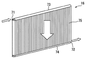
次に、本発明の第9実施形態に関して、図38および図39を用いて説明する。本実施形態では、室外器16の構成に特徴を有する。室外器16は、冷媒が通過する上方口71と、上方口71よりも下方に位置し冷媒が通過する下方口72とを備える。前述の第1実施形態に示すように、冷房時と暖房時とで、室外器16への冷媒入口と冷媒出口とが入れ替わる。本実施形態では、冷房経路のときは、上方口71から冷媒が流入し、下方口72から冷媒が流出する。また暖房経路のときは、下方口72から冷媒が流入し、上方口71から冷媒が流出する。
(Ninth embodiment)
Next, a ninth embodiment of the present invention will be described with reference to FIGS. This embodiment is characterized by the configuration of the
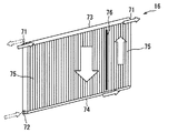
具体的には、室外器16は、図38に示すように、上部のタンク73と、下部のタンク74と、コア部75と、を含む全パスのダウンフロータイプである。上方口71は、上部のタンク73に設けられる。下方口72は、下部のタンク74に設けられる。したがってコア部75の上下方向に冷媒が流れる。
Specifically, as shown in FIG. 38, the
本実施形態では、冷房時には下降流、暖房時には上昇流となるような冷媒流れにする。図38では、冷房時の冷媒流れを示している。暖房時は、図38に示す矢印とは逆方向の流れとなる。 In the present embodiment, the refrigerant flow is a downward flow during cooling and an upward flow during heating. FIG. 38 shows the refrigerant flow during cooling. During heating, the flow is in the direction opposite to the arrow shown in FIG.
冷房時、室外器16は凝縮器として機能する。したがって冷媒はガスから液へと相変化していく。このとき下降流にすることで、冷媒流れ方向と重力方向が同一方向となるので、液冷媒の排出がスムーズになり、均一な冷媒流れを実現できる。
During cooling, the
暖房時、室外器16は蒸発器として機能する。したがって冷媒は液からガスへと相変化していく。冷媒流れが冷房時と逆向きの上昇流とすることで、重力方向と逆向きの流れになり、液冷媒は室外器16に留まりやすくなり、冷媒分配性の均一化が図れる。暖房時は、前述のように内部熱交換器20によって流入する冷媒の乾き度がおおよそ0にできるため、全パス化しても良好な冷媒分配が図れ、圧損も低減することができ、システム性能向上につなげられる。これに対し、従来の図8に記載のような条件で室外器16を作動させようとした場合、入口側のタンク内は液冷媒が慣性力でタンク奥に流れ、奥側のチューブには液冷媒が流れる。逆に、手前側チューブにはガス冷媒が流れ、熱交換面積が有効に利用できず、蒸発性能の低下を招く。
During heating, the
また図39に示すように、全パスではなくUパス構成としてもよい。Uパス構成では、上方口71を上部のタンク73に2箇所設け、冷房時は矢印に示すように、下降流→上昇流とする。そして暖房時は仮想線の矢印で示す下側の下方口72から冷媒を流入させて、1パス目だけ上昇流とし、仮想線の矢印で示す上側の出口となる上方口71から冷媒を流出させる。したがって暖房時は、上昇流のみとする構成である。また冷房時の1パス目の領域は、2パス目の領域よりも大きくなるように、Uターンの仕切部76が設定されている。Uパス構成の場合、2パス目の流路に冷房時は上昇流となるため冷媒の分配性が悪化しないよう過冷却域にする必要がある。
Also, as shown in FIG. 39, a U path configuration may be used instead of all paths. In the U path configuration, two
暖房時には室外器16の入口部の冷媒乾き度を0付近に制御するため、冷媒分配性が良好となる。つまり、1パス目をいかに大きく取れるかが重要となる。一方、1パス目を大きくとることで2パス目は流路が狭くなるため、暖房時の2パス目を通過すると冷媒圧損により暖房性能が低下してしまう。そこで図39に示すように、室外器16は、1パス目が室外器16のコア部75の大部分を占め、冷房時は流路全体を通り、暖房時は1パス目のみを通過するよう構成されることが望ましい。換言すると、暖房時は2パス目を通過しないため、2パス目の流路は1パス目の流路よりも小さくすることが望ましい。
During heating, the refrigerant dryness at the entrance of the
(第10実施形態)
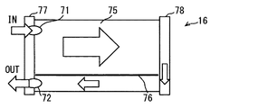
次に、本発明の第10実施形態に関して、図40〜図42を用いて説明する。本実施形態では、前述の第9実施形態と同様に、室外器16の構成に特徴を有する。室外器16は、図40に示すように、左部のタンク77と、右部のタンク78と、コア部75と、を含む全パスのクロスフロータイプである。したがってコア部75の左右方向に冷媒が流れる。上方口71は、左部のタンク77に設けられる。下方口72は、右部のタンク78に設けられる。クロスフロー流れの室外器16においても全パス化することで圧損低減でき、システムの性能向上に貢献できる。クロスフロータイプの室外器16もダウンフロータイプと同様に、入口冷媒乾き度が高くなると、ガス冷媒の体積が増加し、地側のチューブには液冷媒が、天側のチューブにはガス冷媒が流れて、有効に熱交換できない。しかし冷媒乾き度を0近くまで下げることで、液冷媒の体積比率が増加し、チューブに液冷媒を均等に分配できる。
(10th Embodiment)
Next, a tenth embodiment of the present invention will be described with reference to FIGS. The present embodiment is characterized by the configuration of the
また図41に示すように、全パスではなくUパス構成としてもよい。Uパス構成では、上方口71と下方口72を左部のタンク77に設け、冷房時は矢印に示すように、上方口71から冷媒が流入して、右に向かう流れとなり、Uターンして左に向かう流れとする。したがって冷房時は上方から冷媒が流入し、下方から冷媒が流出するように構成される。
Further, as shown in FIG. 41, a U path configuration may be used instead of the full path. In the U-pass configuration, the
暖房時は、冷房時とは逆の流れとする。すなわち、暖房時は、下方口72から冷媒が流入して、右に向かう流れとなり、Uターンして左に向かう流れとする。したがって暖房時は、下方から冷媒が流入し、上方から冷媒が流出するように構成される。
During heating, the flow is opposite to that during cooling. That is, at the time of heating, the refrigerant flows from the
また冷房時の1パス目の領域は、2パス目の領域よりも大きくなるように、Uターンの仕切部76が設定されている。これによって暖房時、流入した液冷媒が、ターンした後は冷媒が二相になってしまうため、下から上に向けて吹き上げる流れの分配性をよくなる。また暖房時には、出口側に近いパスの比率を大きくとることで、冷媒圧損を低減が可能となる。
In addition, the
また図42に示すように、右部のタンク78の下方に下方口72を設けてもよい。冷房時は、図41に示すように、冷房を流してUパスとする。暖房時は、冷房時と同様に冷媒を流入させて、仮想線で示すように、右部のタンク78の下方の下方口72から流出させる。したがって暖房時は、1パスとしている。
Further, as shown in FIG. 42, a
これは暖房時は低圧損が重要なため、冷媒下流側のパスの流路断面積を大きくとりたく、他方では冷媒入口は低乾き度化により分配性が向上するため大きく取りたいという矛盾が発生する。そこで、図42に示すように、入口パスを大きくとり、暖房時は2パス目を通らず出て行くことで低圧損化が可能となる。また、分配や圧損が大きく影響しない冷房時にはコア全体に冷媒を流し有効に利用することができる。 This is because the low pressure loss is important during heating, so there is a contradiction that we want to increase the flow path cross-sectional area of the path downstream of the refrigerant, but on the other hand we want to increase the refrigerant inlet because the distribution is improved by lowering the dryness. To do. Therefore, as shown in FIG. 42, it is possible to reduce the low pressure loss by taking a large entrance path and leaving the second path during heating. Further, at the time of cooling in which distribution and pressure loss do not greatly affect, it is possible to effectively use the refrigerant by flowing it through the entire core.
(その他の実施形態)
以上、本発明の好ましい実施形態について説明したが、本発明は上述した実施形態に何ら制限されることなく、本発明の主旨を逸脱しない範囲において種々変形して実施することが可能である。
(Other embodiments)
The preferred embodiments of the present invention have been described above, but the present invention is not limited to the above-described embodiments, and various modifications can be made without departing from the spirit of the present invention.
上記実施形態の構造は、あくまで例示であって、本発明の範囲はこれらの記載の範囲に限定されるものではない。本発明の範囲は、特許請求の範囲の記載によって示され、さらに特許請求の範囲の記載と均等の意味及び範囲内での全ての変更を含むものである。 The structure of the said embodiment is an illustration to the last, Comprising: The scope of the present invention is not limited to the range of these description. The scope of the present invention is indicated by the description of the scope of claims, and further includes meanings equivalent to the description of the scope of claims and all modifications within the scope.
前述の第1実施形態では、流量調整部24が設けられているが、図43に示すように、流量調整部124がガス冷媒流路19aに設けられていてもよいし、流量調整部24がないヒートポンプサイクル11であってもよい。アキュムレータ19からの液冷媒が、内部熱交換器20へ流入するような構成であればよい。
In the first embodiment described above, the flow
図43に示すヒートポンプシステム10において、ガス冷媒流路19aの流量を流量調整部124によって調整する。ガス冷媒流路19aの流量を調整することによって、液冷媒流路19bの流量を間接的に調整することができる。したがって前述の第1実施形態と同様にアキュムレータ19からの液冷媒の流量を調整し、同様の作用および効果を奏することができる。
In the
前述の第1実施形態では、ガス冷媒流路19aおよび液冷媒流路19bの両方が内部熱交換器20の低圧流路20bに接続されている。しかし前述の第3実施形態のように、ガス冷媒流路19aおよび液冷媒流路19bのうち少なくとも液冷媒流路19bが内部熱交換器20の低圧流路20bに接続されていればよい。これによって内部熱交換器20には、少なくともアキュムレータ19から液冷媒を流入させることができる。
In the first embodiment described above, both the
前述の第8実施形態および第9実施形態では、冷媒流れはUターン(1往復)の構成もあるが、Uターンに限るものではなく、Sターン(1往復半)、Wターン(2往復)、また2往復半以上であってもよい。 In the above-described eighth and ninth embodiments, the refrigerant flow may have a U-turn (one reciprocation) configuration, but is not limited to a U-turn, and an S-turn (one reciprocal half) and a W-turn (two reciprocations). Further, it may be two or more half halves.
また前述の第1実施形態では、暖房時および冷房時、室外器16における冷媒の流れ方向が反対であるが、このような流れ方向に限るものではない。暖房時および冷房時、室外器16における流れ方向が同一であってもよい。
In the first embodiment described above, the flow direction of the refrigerant in the
10…ヒートポンプシステム 11…ヒートポンプサイクル 12…空調ユニット
12a…空調ケース 13…圧縮機 14…凝縮器 15…蒸発器 16…室外器
17…暖房用減圧部(減圧部) 18…冷房用減圧部(減圧部)
19…アキュムレータ 19a…ガス冷媒流路 19b…液冷媒流路
20…内部熱交換器 20a…高圧流路 20b…低圧流路
21…暖房用高圧側開閉部(流路変更部) 22…冷房用開閉部(流路変更部)
23…暖房用低圧側開閉部(流路変更部) 24…流量調整部 25…逆止弁(流路変更部) 26…制御装置(制御部) 53…放熱器 71…上方口 72…下方口
73…上部のタンク 74…下部のタンク 75…コア部
DESCRIPTION OF
DESCRIPTION OF
DESCRIPTION OF
Claims (9)
冷媒を減圧する減圧部(17,18)と、
冷媒と外気とを熱交換させる室外器(16)と、
冷媒を蒸発させる蒸発器(15)と、
冷媒を凝縮させる凝縮器(14)と、
高圧の冷媒が流れる高圧流路(20a)と低圧の冷媒が流れる低圧流路(20b)とを有し、前記高圧流路と前記低圧流路とを流れる冷媒間で熱交換させる内部熱交換器(20)と、
冷媒をガス冷媒と液冷媒とに分離するアキュムレータ(19)と、
冷媒が流れる経路を変更する流路変更部(21〜23,25)と、を含み、
前記流路変更部は、
前記圧縮機、前記室外器、前記内部熱交換器の前記高圧流路、前記減圧部、前記蒸発器、前記アキュムレータ、前記内部熱交換器の前記低圧流路、前記圧縮機の順で冷媒が循環する冷房経路と、
前記圧縮機、前記凝縮器、前記内部熱交換器の前記高圧流路、前記減圧部、前記室外器、前記アキュムレータ、前記内部熱交換器の前記低圧流路、前記圧縮機の順で冷媒が循環する暖房経路と、を変更し、
前記アキュムレータは、分離したガス冷媒を流出させるガス冷媒流路(19a)と、分離した液冷媒を流出させる液冷媒流路(19b)と、を備え、
前記ガス冷媒流路および前記液冷媒流路のうち少なくとも前記液冷媒流路は、前記内部熱交換器の前記低圧流路に接続されており、
前記冷房経路は、前記圧縮機、前記室外器、前記凝縮器、前記内部熱交換器の前記高圧流路、前記減圧部、前記蒸発器、前記アキュムレータ、前記内部熱交換器の前記低圧流路、前記圧縮機の順で冷媒が循環することを特徴とするヒートポンプシステム。 A compressor (13) for compressing and discharging the refrigerant;
A decompression section (17, 18) for decompressing the refrigerant;
An outdoor unit (16) for exchanging heat between the refrigerant and the outside air;
An evaporator (15) for evaporating the refrigerant;
A condenser (14) for condensing the refrigerant;
An internal heat exchanger having a high-pressure channel (20a) through which a high-pressure refrigerant flows and a low-pressure channel (20b) through which a low-pressure refrigerant flows, and exchanging heat between the refrigerant flowing through the high-pressure channel and the low-pressure channel (20) and
An accumulator (19) for separating the refrigerant into a gas refrigerant and a liquid refrigerant;
A flow path changing unit (21 to 23, 25) that changes a path through which the refrigerant flows,
The flow path changing unit is
The refrigerant circulates in the order of the compressor, the outdoor unit, the high-pressure channel of the internal heat exchanger, the decompression unit, the evaporator, the accumulator, the low-pressure channel of the internal heat exchanger, and the compressor. Cooling path to
The refrigerant circulates in the order of the compressor, the condenser, the high-pressure channel of the internal heat exchanger, the decompression unit, the outdoor unit, the accumulator, the low-pressure channel of the internal heat exchanger, and the compressor. Change the heating route,
The accumulator includes a gas refrigerant channel (19a) for flowing out the separated gas refrigerant, and a liquid refrigerant channel (19b) for flowing out the separated liquid refrigerant,
At least the liquid refrigerant channel of the gas refrigerant channel and the liquid refrigerant channel is connected to the low pressure channel of the internal heat exchanger ,
The cooling path includes the compressor, the outdoor unit, the condenser, the high-pressure channel of the internal heat exchanger, the decompression unit, the evaporator, the accumulator, the low-pressure channel of the internal heat exchanger, A heat pump system, wherein the refrigerant circulates in the order of the compressor .
前記ガス冷媒流路は、前記内部熱交換器の前記低圧流路の下流側に接続されることを特徴とする請求項1または2に記載のヒートポンプシステム。 The liquid refrigerant flow path is connected to the low pressure flow path of the internal heat exchanger;
The heat pump system according to claim 1, wherein the gas refrigerant flow path is connected to a downstream side of the low pressure flow path of the internal heat exchanger.
冷媒を減圧する減圧部(17,18)と、
冷媒と外気とを熱交換させる室外器(16)と、
冷媒を蒸発させる蒸発器(15)と、
冷媒を凝縮させる凝縮器(14)と、
高圧の冷媒が流れる高圧流路(20a)と低圧の冷媒が流れる低圧流路(20b)とを有し、前記高圧流路と前記低圧流路とを流れる冷媒間で熱交換させる内部熱交換器(20)と、
冷媒をガス冷媒と液冷媒とに分離するアキュムレータ(19)と、
冷媒が流れる経路を変更する流路変更部(21〜23,25)と、を含み、
前記流路変更部は、
前記圧縮機、前記室外器、前記内部熱交換器の前記高圧流路、前記減圧部、前記蒸発器、前記アキュムレータ、前記内部熱交換器の前記低圧流路、前記圧縮機の順で冷媒が循環する冷房経路と、
前記圧縮機、前記凝縮器、前記内部熱交換器の前記高圧流路、前記減圧部、前記室外器、前記アキュムレータ、前記内部熱交換器の前記低圧流路、前記圧縮機の順で冷媒が循環する暖房経路と、を変更し、
前記アキュムレータは、分離したガス冷媒を流出させるガス冷媒流路(19a)と、分離した液冷媒を流出させる液冷媒流路(19b)と、を備え、
前記ガス冷媒流路および前記液冷媒流路のうち少なくとも前記液冷媒流路は、前記内部熱交換器の前記低圧流路に接続されており、
前記流路変更部は、
前記圧縮機、前記室外器、前記内部熱交換器の前記高圧流路、前記減圧部、前記蒸発器、前記アキュムレータ、前記内部熱交換器の前記低圧流路、前記圧縮機の順で冷媒が循環する冷房経路と、
前記圧縮機、前記凝縮器、前記内部熱交換器の前記高圧流路、前記減圧部、前記室外器、前記アキュムレータ、前記内部熱交換器の前記低圧流路、前記圧縮機の順で冷媒が循環する第1暖房経路と、
前記圧縮機、前記凝縮器、前記蒸発器、前記アキュムレータ、前記内部熱交換器の前記低圧流路、前記圧縮機の順で冷媒が循環する第2暖房経路と、
前記圧縮機、前記凝縮器、前記内部熱交換器の前記高圧流路、前記減圧部、前記室外器、前記アキュムレータ、前記内部熱交換器の前記低圧流路、前記圧縮機の順で冷媒が循環しつつ、前記凝縮器の下流で分岐して前記高圧流路ではなく前記蒸発器を経て前記アキュムレータに流れる経路を含む第1除湿暖房経路と、
前記圧縮機、前記室外器、前記内部熱交換器の前記高圧流路、前記減圧部、前記蒸発器、前記アキュムレータ、前記内部熱交換器の前記低圧流路、前記圧縮機の順で冷媒が循環しつつ、前記圧縮機の下流で分岐して前記室外器ではなく前記凝縮器を経て前記蒸発器に流れる経路を含む第2除湿暖房経路と、
前記圧縮機、前記室外器、前記内部熱交換器の前記高圧流路、前記凝縮器、前記アキュムレータ、前記内部熱交換器の前記低圧流路、前記圧縮機の順で冷媒が循環する除霜経路と、を変更することを特徴とするヒートポンプシステム。 A compressor (13) for compressing and discharging the refrigerant;
A decompression section (17, 18) for decompressing the refrigerant;
An outdoor unit (16) for exchanging heat between the refrigerant and the outside air;
An evaporator (15) for evaporating the refrigerant;
A condenser (14) for condensing the refrigerant;
An internal heat exchanger having a high-pressure channel (20a) through which a high-pressure refrigerant flows and a low-pressure channel (20b) through which a low-pressure refrigerant flows, and exchanging heat between the refrigerant flowing through the high-pressure channel and the low-pressure channel (20) and
An accumulator (19) for separating the refrigerant into a gas refrigerant and a liquid refrigerant;
A flow path changing unit (21 to 23, 25) that changes a path through which the refrigerant flows,
The flow path changing unit is
The refrigerant circulates in the order of the compressor, the outdoor unit, the high-pressure channel of the internal heat exchanger, the decompression unit, the evaporator, the accumulator, the low-pressure channel of the internal heat exchanger, and the compressor. Cooling path to
The refrigerant circulates in the order of the compressor, the condenser, the high-pressure channel of the internal heat exchanger, the decompression unit, the outdoor unit, the accumulator, the low-pressure channel of the internal heat exchanger, and the compressor. Change the heating route,
The accumulator includes a gas refrigerant channel (19a) for flowing out the separated gas refrigerant, and a liquid refrigerant channel (19b) for flowing out the separated liquid refrigerant,
At least the liquid refrigerant channel of the gas refrigerant channel and the liquid refrigerant channel is connected to the low pressure channel of the internal heat exchanger ,
The flow path changing unit is
The refrigerant circulates in the order of the compressor, the outdoor unit, the high-pressure channel of the internal heat exchanger, the decompression unit, the evaporator, the accumulator, the low-pressure channel of the internal heat exchanger, and the compressor. Cooling path to
The refrigerant circulates in the order of the compressor, the condenser, the high-pressure channel of the internal heat exchanger, the decompression unit, the outdoor unit, the accumulator, the low-pressure channel of the internal heat exchanger, and the compressor. A first heating path to
A second heating path through which refrigerant circulates in the order of the compressor, the condenser, the evaporator, the accumulator, the low-pressure flow path of the internal heat exchanger, and the compressor;
The refrigerant circulates in the order of the compressor, the condenser, the high-pressure channel of the internal heat exchanger, the decompression unit, the outdoor unit, the accumulator, the low-pressure channel of the internal heat exchanger, and the compressor. However, a first dehumidifying and heating path including a path that branches downstream of the condenser and flows to the accumulator through the evaporator instead of the high-pressure channel;
The refrigerant circulates in the order of the compressor, the outdoor unit, the high-pressure channel of the internal heat exchanger, the decompression unit, the evaporator, the accumulator, the low-pressure channel of the internal heat exchanger, and the compressor. However, a second dehumidifying heating path including a path that branches downstream of the compressor and flows to the evaporator through the condenser instead of the outdoor unit,
The compressor, the outdoor unit, the high-pressure channel of the internal heat exchanger, the condenser, the accumulator, the low-pressure channel of the internal heat exchanger, and a defrost path through which the refrigerant circulates in the order of the compressor. And a heat pump system characterized by changing .
冷媒を減圧する減圧部(17,18)と、
冷媒と外気とを熱交換させる室外器(16)と、
冷媒を蒸発させる蒸発器(15)と、
冷媒を凝縮させる凝縮器(14)と、
冷媒をガス冷媒と液冷媒とに分離するアキュムレータ(19)と、
冷媒が流れる経路を変更する流路変更部(21〜23,25)と、を含み、
前記流路変更部は、
前記圧縮機、前記室外器、前記減圧部、前記蒸発器、前記アキュムレータ、前記圧縮機で冷媒が循環する冷房経路と、
前記圧縮機、前記凝縮器、前記減圧部、前記室外器、前記アキュムレータ、前記圧縮機の順で冷媒が循環する暖房経路と、
前記圧縮機、前記室外器、前記凝縮器、前記アキュムレータ、前記圧縮機の順で冷媒が循環する除霜経路と、を変更することを特徴とするヒートポンプシステム。 A compressor (13) for compressing and discharging the refrigerant;
A decompression section (17, 18) for decompressing the refrigerant;
An outdoor unit (16) for exchanging heat between the refrigerant and the outside air;
An evaporator (15) for evaporating the refrigerant;
A condenser (14) for condensing the refrigerant;
An accumulator (19) for separating the refrigerant into a gas refrigerant and a liquid refrigerant;
A flow path changing unit (21 to 23, 25) that changes a path through which the refrigerant flows,
The flow path changing unit is
A cooling path through which refrigerant circulates in the compressor, the outdoor unit, the decompression unit, the evaporator, the accumulator, and the compressor;
A heating path through which refrigerant circulates in the order of the compressor, the condenser, the decompression unit, the outdoor unit, the accumulator, and the compressor;
The heat pump system characterized by changing the compressor, the outdoor unit, the condenser, the accumulator, and the defrosting path through which the refrigerant circulates in the order of the compressor.
前記制御部は、前記除霜経路による冷媒の循環および循環停止を、前記圧縮機の吸入側の冷媒圧力および外気温を用いて判断することを特徴とする請求項5に記載のヒートポンプシステム。 A control unit (26) for controlling a discharge amount of the compressor and a path by the flow path changing unit;
6. The heat pump system according to claim 5 , wherein the control unit determines the refrigerant circulation and the circulation stop by the defrosting path using the refrigerant pressure and the outside air temperature on the suction side of the compressor.
前記冷房経路のときは、前記上方口から冷媒が流入し、
前記暖房経路のときは、前記下方口から冷媒が流入することを特徴とする請求項1〜6のいずれか1つに記載のヒートポンプシステム。 The outdoor unit includes an upper port (71) through which the refrigerant passes, and a lower port (72) that is located below the upper port and through which the refrigerant passes,
When the cooling path, the refrigerant flows from the upper port,
The heat pump system according to any one of claims 1 to 6 , wherein a refrigerant flows in from the lower opening during the heating path.
前記上部のタンクに設けられ、冷媒が通過する上方口(71)と、
前記下部のタンクに設けられ、冷媒が通過する下方口(72)とを備え、
前記冷房経路のときは、前記上方口から冷媒が流入し、前記下方口から冷媒が流出し、 前記暖房経路のときは、前記下方口から冷媒が流入し、前記上方口から冷媒が流出することを特徴とする請求項1〜6のいずれか1つに記載のヒートポンプシステム。 The outdoor unit is a downflow type including an upper tank (73), a lower tank (74), and a core part (75),
An upper port (71) provided in the upper tank and through which refrigerant passes;
A lower opening (72) provided in the lower tank and through which refrigerant passes;
In the cooling path, the refrigerant flows in from the upper port, and the refrigerant flows out from the lower port. In the heating path, the refrigerant flows in from the lower port, and the refrigerant flows out from the upper port. The heat pump system according to any one of claims 1 to 6 .
前記制御部は、前記暖房経路のとき、前記圧縮機に吸入する前の冷媒物性から過熱度を推定し、前記過熱度が所定の目標値に近づくよう前記流量調整部を制御することを特徴とする請求項2に記載のヒートポンプシステム。 A control unit (26) for controlling the flow rate adjustment unit;
The control unit estimates the degree of superheat from the physical properties of the refrigerant before sucking into the compressor during the heating path, and controls the flow rate adjustment unit so that the degree of superheat approaches a predetermined target value. The heat pump system according to claim 2 .
Priority Applications (4)
| Application Number | Priority Date | Filing Date | Title |
|---|---|---|---|
| PCT/JP2016/070486 WO2017022421A1 (en) | 2015-08-04 | 2016-07-12 | Heat pump system |
| US15/749,514 US11179999B2 (en) | 2015-08-04 | 2016-07-12 | Heat pump system |
| DE112016003558.6T DE112016003558B4 (en) | 2015-08-04 | 2016-07-12 | Heat pump system |
| CN201680045427.0A CN107923662B (en) | 2015-08-04 | 2016-07-12 | Heat pump system |
Applications Claiming Priority (2)
| Application Number | Priority Date | Filing Date | Title |
|---|---|---|---|
| JP2015154332 | 2015-08-04 | ||
| JP2015154332 | 2015-08-04 |
Publications (3)
| Publication Number | Publication Date |
|---|---|
| JP2017030724A JP2017030724A (en) | 2017-02-09 |
| JP2017030724A5 JP2017030724A5 (en) | 2017-07-27 |
| JP6323489B2 true JP6323489B2 (en) | 2018-05-16 |
Family
ID=57985442
Family Applications (1)
| Application Number | Title | Priority Date | Filing Date |
|---|---|---|---|
| JP2016075387A Active JP6323489B2 (en) | 2015-08-04 | 2016-04-04 | Heat pump system |
Country Status (4)
| Country | Link |
|---|---|
| US (1) | US11179999B2 (en) |
| JP (1) | JP6323489B2 (en) |
| CN (1) | CN107923662B (en) |
| DE (1) | DE112016003558B4 (en) |
Families Citing this family (17)
| Publication number | Priority date | Publication date | Assignee | Title |
|---|---|---|---|---|
| CN106415153B (en) * | 2014-06-27 | 2019-04-23 | 三菱电机株式会社 | Refrigerating circulatory device |
| JP6565744B2 (en) * | 2016-03-10 | 2019-08-28 | 株式会社デンソー | Air conditioner |
| US10556487B2 (en) * | 2016-03-18 | 2020-02-11 | Denso Corporation | Accumulating/receiving device and heat pump system |
| JP6853138B2 (en) * | 2017-08-07 | 2021-03-31 | 本田技研工業株式会社 | Vehicle air conditioner |
| US11358438B2 (en) * | 2017-08-08 | 2022-06-14 | Hangzhou Sanhua Research Institute Co., Ltd. | Automotive air conditioning system |
| US10752087B2 (en) * | 2018-01-10 | 2020-08-25 | Denso International America, Inc. | Vehicle refrigeration system including cabin and outdoor condenser circuits with a holding reservoir and a bypass controlled outside subcool heat exchanger for heating output control of condensers |
| WO2019198175A1 (en) * | 2018-04-11 | 2019-10-17 | 三菱電機株式会社 | Refrigeration cycle device |
| US11747057B2 (en) * | 2018-06-14 | 2023-09-05 | Hangzhou Sanhua Research Institute Co., Ltd. | Heat pump system |
| US11346583B2 (en) * | 2018-06-27 | 2022-05-31 | Emerson Climate Technologies, Inc. | Climate-control system having vapor-injection compressors |
| WO2020036067A1 (en) | 2018-08-13 | 2020-02-20 | 日本碍子株式会社 | Heating element for heating passenger compartment, method of use thereof, and heater for heating passenger compartment |
| CN110131817A (en) * | 2019-05-10 | 2019-08-16 | 格力电器(合肥)有限公司 | Air-conditioning heating recycles the supercooling heat-exchange system and air conditioner of lower refrigerant |
| US11021041B2 (en) | 2019-06-18 | 2021-06-01 | Ford Global Technologies, Llc | Integrated thermal management system |
| US11254190B2 (en) | 2019-06-18 | 2022-02-22 | Ford Global Technologies, Llc | Vapor injection heat pump and control method |
| KR20210083047A (en) | 2019-12-26 | 2021-07-06 | 엘지전자 주식회사 | An air conditioning apparatus |
| KR20210094213A (en) | 2020-01-21 | 2021-07-29 | 엘지전자 주식회사 | An air conditioning apparatus |
| IT202100025904A1 (en) * | 2021-10-08 | 2023-04-08 | Clivet S P A | METHOD FOR DEFROSTING AN AIR HEAT EXCHANGER IN A MULTI-PURPOSE HEAT PUMP UNIT |
| JP2024000108A (en) * | 2022-06-20 | 2024-01-05 | サンデン株式会社 | Air conditioning vehicle |
Family Cites Families (38)
| Publication number | Priority date | Publication date | Assignee | Title |
|---|---|---|---|---|
| JPH04132369U (en) * | 1991-05-23 | 1992-12-08 | 三菱重工業株式会社 | Air conditioner refrigerant circuit |
| US5598887A (en) | 1993-10-14 | 1997-02-04 | Sanden Corporation | Air conditioner for vehicles |
| JP3233771B2 (en) * | 1994-02-25 | 2001-11-26 | サンデン株式会社 | Vehicle air conditioner |
| JPH08166172A (en) | 1994-12-14 | 1996-06-25 | Sanyo Electric Co Ltd | Refrigerating equipment |
| US5704219A (en) | 1995-08-01 | 1998-01-06 | Nippondenso Co., Ltd. | Air conditioning apparatus |
| JP2001201213A (en) * | 2000-01-21 | 2001-07-27 | Denso Corp | Supercritical refrigeration cycle |
| US6505476B1 (en) | 1999-10-28 | 2003-01-14 | Denso Corporation | Refrigerant cycle system with super-critical refrigerant pressure |
| JP4042481B2 (en) * | 2002-06-26 | 2008-02-06 | 株式会社デンソー | Air conditioner |
| JP2004089974A (en) | 2002-09-02 | 2004-03-25 | Shigeru Sato | Electroosmosis dewatering method |
| JP3941638B2 (en) | 2002-09-12 | 2007-07-04 | 株式会社デンソー | Air conditioner for vehicles |
| JP2005262948A (en) * | 2004-03-17 | 2005-09-29 | Calsonic Kansei Corp | Vehicular air-conditioner |
| JP2005337592A (en) * | 2004-05-27 | 2005-12-08 | Tgk Co Ltd | Refrigerating cycle |
| EP1695849A1 (en) | 2005-02-28 | 2006-08-30 | Sanyo Electric Co., Ltd. | Refrigerant cycle unit |
| JP2006242402A (en) * | 2005-02-28 | 2006-09-14 | Sanyo Electric Co Ltd | Refrigerant cycle device |
| JP4595717B2 (en) | 2005-05-24 | 2010-12-08 | 株式会社デンソー | Vapor compression refrigeration cycle using ejector |
| US7779647B2 (en) | 2005-05-24 | 2010-08-24 | Denso Corporation | Ejector and ejector cycle device |
| DE102006024796B4 (en) * | 2006-03-17 | 2009-11-26 | Konvekta Ag | air conditioning |
| JP2008190763A (en) | 2007-02-02 | 2008-08-21 | Calsonic Kansei Corp | Internal heat exchanger structure for air conditioning system |
| JP5751028B2 (en) * | 2010-06-10 | 2015-07-22 | 株式会社デンソー | Heat pump cycle |
| WO2012012491A2 (en) * | 2010-07-23 | 2012-01-26 | Carrier Corporation | Ejector cycle refrigerant separator |
| JP2012132578A (en) * | 2010-12-20 | 2012-07-12 | Panasonic Corp | Refrigerating cycle device |
| JP5934181B2 (en) * | 2011-03-03 | 2016-06-15 | サンデンホールディングス株式会社 | Air conditioner for vehicles |
| DE102012204404B4 (en) * | 2011-03-25 | 2022-09-08 | Denso Corporation | heat exchange system and vehicle refrigeration cycle system |
| DE102012205200B4 (en) | 2011-04-04 | 2020-06-18 | Denso Corporation | Refrigerant cycle device |
| JP5929372B2 (en) | 2011-04-04 | 2016-06-08 | 株式会社デンソー | Refrigeration cycle equipment |
| US9464832B2 (en) | 2011-11-30 | 2016-10-11 | Mitsubishi Electric Corporation | Refrigeration cycle device, equipment, and refrigeration cycle method |
| JP5944154B2 (en) * | 2011-12-09 | 2016-07-05 | サンデンホールディングス株式会社 | Air conditioner for vehicles |
| JP6216113B2 (en) * | 2012-04-02 | 2017-10-18 | サンデンホールディングス株式会社 | Heat exchanger and heat pump system using the same |
| JP2014009868A (en) * | 2012-06-28 | 2014-01-20 | Denso Corp | Heat pump cycle |
| JP2014092325A (en) | 2012-11-05 | 2014-05-19 | Panasonic Corp | Heat pump device for vehicle |
| JP5958411B2 (en) * | 2013-04-22 | 2016-08-02 | 株式会社デンソー | HEAT PUMP SYSTEM AND ITS CONTROL DEVICE |
| JP2014214913A (en) * | 2013-04-23 | 2014-11-17 | 三菱電機株式会社 | Oil return controller and refrigerator |
| JP6070418B2 (en) | 2013-05-29 | 2017-02-01 | 株式会社デンソー | Heat pump cycle |
| JP6257940B2 (en) * | 2013-07-11 | 2018-01-10 | 三菱重工オートモーティブサーマルシステムズ株式会社 | Heat pump type vehicle air conditioning system and defrosting method thereof |
| JP6298648B2 (en) | 2014-02-17 | 2018-03-20 | 矢崎総業株式会社 | Backup signal generation circuit for load control |
| JP6022058B2 (en) * | 2014-02-27 | 2016-11-09 | 三菱電機株式会社 | Heat source side unit and refrigeration cycle apparatus |
| CN107208937A (en) * | 2015-01-23 | 2017-09-26 | 三菱电机株式会社 | Conditioner |
| JP2016075387A (en) | 2015-06-12 | 2016-05-12 | 井上スダレ株式会社 | Pipe joint |
-
2016
- 2016-04-04 JP JP2016075387A patent/JP6323489B2/en active Active
- 2016-07-12 CN CN201680045427.0A patent/CN107923662B/en active Active
- 2016-07-12 DE DE112016003558.6T patent/DE112016003558B4/en active Active
- 2016-07-12 US US15/749,514 patent/US11179999B2/en active Active
Also Published As
| Publication number | Publication date |
|---|---|
| JP2017030724A (en) | 2017-02-09 |
| US20180222287A1 (en) | 2018-08-09 |
| DE112016003558T5 (en) | 2018-04-12 |
| CN107923662B (en) | 2020-06-30 |
| DE112016003558B4 (en) | 2021-08-19 |
| US11179999B2 (en) | 2021-11-23 |
| CN107923662A (en) | 2018-04-17 |
Similar Documents
| Publication | Publication Date | Title |
|---|---|---|
| JP6323489B2 (en) | Heat pump system | |
| JP5611072B2 (en) | Heat pump air conditioner for vehicle and defrosting method thereof | |
| CN107428222B (en) | Vehicle heat pump system | |
| JP6015636B2 (en) | Heat pump system | |
| JP6189098B2 (en) | Heat pump air conditioning system for vehicles | |
| JP5187786B2 (en) | Vehicle heat pump system | |
| CN107636401B (en) | Refrigeration cycle device | |
| JP2019501068A (en) | Vehicle heat pump system | |
| KR101669826B1 (en) | Heat pump system for vehicle | |
| KR101450636B1 (en) | Heat pump system for vehicle | |
| JP7173064B2 (en) | thermal management system | |
| JP2014228190A (en) | Refrigeration cycle device | |
| KR101474808B1 (en) | Heat pump system for vehicle | |
| JP6004367B2 (en) | Air conditioner for vehicles | |
| JP2000052757A (en) | Air-conditioning and heating equipment for automobile | |
| JP2014126209A (en) | Refrigeration cycle device | |
| JP2014156143A (en) | Vehicular air-conditioning device | |
| JP5884080B2 (en) | Air conditioner for vehicles | |
| JP5510374B2 (en) | Heat exchange system | |
| JP2014034301A (en) | Refrigeration cycle device | |
| KR101941026B1 (en) | Heat pump system for vehicle | |
| KR101146477B1 (en) | Heat Pump System for Car | |
| KR101622631B1 (en) | Heat pump system for vehicle and its control method | |
| TWI779590B (en) | Vehicle Air Conditioning System | |
| TWI779591B (en) | Vehicle Air Conditioning System |
Legal Events
| Date | Code | Title | Description |
|---|---|---|---|
| A521 | Request for written amendment filed |
Free format text: JAPANESE INTERMEDIATE CODE: A523 Effective date: 20170614 |
|
| A621 | Written request for application examination |
Free format text: JAPANESE INTERMEDIATE CODE: A621 Effective date: 20170614 |
|
| TRDD | Decision of grant or rejection written | ||
| A01 | Written decision to grant a patent or to grant a registration (utility model) |
Free format text: JAPANESE INTERMEDIATE CODE: A01 Effective date: 20180313 |
|
| A61 | First payment of annual fees (during grant procedure) |
Free format text: JAPANESE INTERMEDIATE CODE: A61 Effective date: 20180326 |
|
| R151 | Written notification of patent or utility model registration |
Ref document number: 6323489 Country of ref document: JP Free format text: JAPANESE INTERMEDIATE CODE: R151 |
|
| R250 | Receipt of annual fees |
Free format text: JAPANESE INTERMEDIATE CODE: R250 |
|
| R250 | Receipt of annual fees |
Free format text: JAPANESE INTERMEDIATE CODE: R250 |
|
| R250 | Receipt of annual fees |
Free format text: JAPANESE INTERMEDIATE CODE: R250 |