CN111033148A - Refrigeration cycle device - Google Patents
Refrigeration cycle device Download PDFInfo
- Publication number
- CN111033148A CN111033148A CN201880054763.0A CN201880054763A CN111033148A CN 111033148 A CN111033148 A CN 111033148A CN 201880054763 A CN201880054763 A CN 201880054763A CN 111033148 A CN111033148 A CN 111033148A
- Authority
- CN
- China
- Prior art keywords
- heat
- refrigerant
- temperature
- heating
- air
- Prior art date
- Legal status (The legal status is an assumption and is not a legal conclusion. Google has not performed a legal analysis and makes no representation as to the accuracy of the status listed.)
- Pending
Links
Images


Classifications
-
- B—PERFORMING OPERATIONS; TRANSPORTING
- B60—VEHICLES IN GENERAL
- B60H—ARRANGEMENTS OF HEATING, COOLING, VENTILATING OR OTHER AIR-TREATING DEVICES SPECIALLY ADAPTED FOR PASSENGER OR GOODS SPACES OF VEHICLES
- B60H1/00—Heating, cooling or ventilating [HVAC] devices
- B60H1/22—Heating, cooling or ventilating [HVAC] devices the heat being derived otherwise than from the propulsion plant
-
- F—MECHANICAL ENGINEERING; LIGHTING; HEATING; WEAPONS; BLASTING
- F25—REFRIGERATION OR COOLING; COMBINED HEATING AND REFRIGERATION SYSTEMS; HEAT PUMP SYSTEMS; MANUFACTURE OR STORAGE OF ICE; LIQUEFACTION SOLIDIFICATION OF GASES
- F25B—REFRIGERATION MACHINES, PLANTS OR SYSTEMS; COMBINED HEATING AND REFRIGERATION SYSTEMS; HEAT PUMP SYSTEMS
- F25B1/00—Compression machines, plants or systems with non-reversible cycle
-
- F—MECHANICAL ENGINEERING; LIGHTING; HEATING; WEAPONS; BLASTING
- F25—REFRIGERATION OR COOLING; COMBINED HEATING AND REFRIGERATION SYSTEMS; HEAT PUMP SYSTEMS; MANUFACTURE OR STORAGE OF ICE; LIQUEFACTION SOLIDIFICATION OF GASES
- F25B—REFRIGERATION MACHINES, PLANTS OR SYSTEMS; COMBINED HEATING AND REFRIGERATION SYSTEMS; HEAT PUMP SYSTEMS
- F25B29/00—Combined heating and refrigeration systems, e.g. operating alternately or simultaneously
-
- F—MECHANICAL ENGINEERING; LIGHTING; HEATING; WEAPONS; BLASTING
- F25—REFRIGERATION OR COOLING; COMBINED HEATING AND REFRIGERATION SYSTEMS; HEAT PUMP SYSTEMS; MANUFACTURE OR STORAGE OF ICE; LIQUEFACTION SOLIDIFICATION OF GASES
- F25B—REFRIGERATION MACHINES, PLANTS OR SYSTEMS; COMBINED HEATING AND REFRIGERATION SYSTEMS; HEAT PUMP SYSTEMS
- F25B39/00—Evaporators; Condensers
- F25B39/04—Condensers
-
- F—MECHANICAL ENGINEERING; LIGHTING; HEATING; WEAPONS; BLASTING
- F25—REFRIGERATION OR COOLING; COMBINED HEATING AND REFRIGERATION SYSTEMS; HEAT PUMP SYSTEMS; MANUFACTURE OR STORAGE OF ICE; LIQUEFACTION SOLIDIFICATION OF GASES
- F25B—REFRIGERATION MACHINES, PLANTS OR SYSTEMS; COMBINED HEATING AND REFRIGERATION SYSTEMS; HEAT PUMP SYSTEMS
- F25B5/00—Compression machines, plants or systems, with several evaporator circuits, e.g. for varying refrigerating capacity
- F25B5/02—Compression machines, plants or systems, with several evaporator circuits, e.g. for varying refrigerating capacity arranged in parallel
-
- F—MECHANICAL ENGINEERING; LIGHTING; HEATING; WEAPONS; BLASTING
- F25—REFRIGERATION OR COOLING; COMBINED HEATING AND REFRIGERATION SYSTEMS; HEAT PUMP SYSTEMS; MANUFACTURE OR STORAGE OF ICE; LIQUEFACTION SOLIDIFICATION OF GASES
- F25B—REFRIGERATION MACHINES, PLANTS OR SYSTEMS; COMBINED HEATING AND REFRIGERATION SYSTEMS; HEAT PUMP SYSTEMS
- F25B5/00—Compression machines, plants or systems, with several evaporator circuits, e.g. for varying refrigerating capacity
- F25B5/04—Compression machines, plants or systems, with several evaporator circuits, e.g. for varying refrigerating capacity arranged in series
Abstract
A refrigeration cycle device (10) is configured to have a compressor (11), a high-temperature-side water-refrigerant heat exchanger (12), a branching section (14a), a cooling expansion valve (15a), a heat-absorbing expansion valve (15b), an indoor evaporator (16), and an outdoor evaporator (18). One refrigerant outlet of the branch portion (14a) is connected to a cooling expansion valve (15a) and an indoor evaporator (16), and the other refrigerant outlet is connected to a heat absorption expansion valve (15b) and an outdoor evaporator (18). In the cooling mode, the refrigerant circuit is switched to a refrigerant circuit in which the refrigerant decompressed by the cooling expansion valve (15a) exchanges heat with the blown air in the indoor evaporator (16), and in the heating mode, the refrigerant circuit is switched to a refrigerant circuit in which the refrigerant decompressed by the heat-absorbing expansion valve (15b) exchanges heat in the outdoor evaporator (18), absorbs heat from the outside air, and heats the blown air.
Description
Cross reference to related applications
The application is based on Japanese patent application No. 2017-187648, applied on 9/28/2017, and the disclosure of the application is incorporated by reference.
Technical Field
The present invention relates to a refrigeration cycle apparatus.
Background
Conventionally, as a technique relating to a vapor compression refrigeration cycle device applied to an air conditioner, a technique described in patent document 1 is known.
The refrigeration cycle of patent document 1 is configured to be capable of switching a refrigerant circuit and the like in accordance with a plurality of operation modes such as a cooling mode for cooling the feed air blown into the vehicle interior as the air conditioning target space of the apparatus, a heating mode for heating the feed air, and a dehumidification and heating mode for reheating the feed air after cooling and dehumidification.
The refrigeration cycle device of patent document 1 includes a plurality of heat exchangers such as an indoor condenser, an outdoor heat exchanger, and an indoor evaporator, and is configured to switch the functions of the heat exchangers according to an operation mode.
Specifically, in the cooling mode, the refrigerant circuit is switched so that the outdoor heat exchanger functions as a radiator and the indoor evaporator functions as a heat absorber. In the heating mode, the refrigerant circuit is switched to one in which the indoor condenser functions as a radiator and the outdoor heat exchanger functions as a heat absorber. In the dehumidification and heating mode, the refrigerant circuit is switched to one in which the indoor condenser functions as a radiator and both the indoor evaporator and the outdoor heat exchanger function as heat absorbers.
Documents of the prior art
Patent document
Patent document 1 Japanese patent laid-open publication No. 2017-133823
According to the research of the inventors of the present application, in a refrigeration cycle apparatus which includes a plurality of heat exchangers and switches the same heat exchanger (in patent document 1, an outdoor heat exchanger) to either one of a radiator and a heat absorber according to an operation mode as in patent document 1, a pressure adjustment valve and a switching valve are required in a refrigerant circuit, and thus the circuit configuration becomes complicated. Further, since it is necessary to obtain an appropriate cycle balance in each operation mode, complicated control is also necessary in association with switching.
Disclosure of Invention
The present invention has been made in view of these problems, and an object of the present invention is to simplify a circuit configuration and control of switching operation modes in a refrigeration cycle apparatus including a plurality of heat absorbers and configured to be capable of switching operation modes.
A refrigeration cycle apparatus according to a first characteristic example of the present invention includes:
a compressor that compresses and discharges a refrigerant;
a heating unit that heats a fluid to be heat-exchanged using, as a heat source, heat of a refrigerant discharged from the compressor;
a branching portion that branches a flow of the high-pressure refrigerant flowing out of the heating portion;
a cooling decompression unit that decompresses the refrigerant flowing out of one of the refrigerant outlet ports of the branch portion;
a heat absorber for cooling that evaporates the refrigerant decompressed by the decompression section for cooling by exchanging heat with a fluid to be heat-exchanged;
a heating decompression portion for decompressing the refrigerant flowing out from the other refrigerant outlet of the branch portion;
a heat absorber for heating that evaporates the refrigerant decompressed by the decompression section for heating by exchanging heat with outside air as a heat source fluid; and
a circuit switching unit that switches between a refrigerant circuit that causes a refrigerant to flow into the heat absorber for cooling and a refrigerant circuit that causes a refrigerant to flow into the heat absorber for heating,
in a cooling mode for cooling the fluid to be heat-exchanged, the circuit switching unit switches to a refrigerant circuit for exchanging heat of the refrigerant in the cooling heat absorber, and in a heating mode for heating the fluid to be heat-exchanged, the circuit switching unit switches to a refrigerant circuit for exchanging heat of the refrigerant in the heating heat absorber.
According to this refrigeration cycle apparatus, the circuit switching unit can switch and connect the refrigerant circuit on the cooling decompression unit and the cooling heat absorber side, and the refrigerant circuit on the heating decompression unit and the heating heat absorber side, with respect to the branching unit.
Specifically, in the cooling mode, the refrigerant circuit can be switched to cool the fluid to be heat-exchanged by exchanging heat of the refrigerant in the cooling heat absorber. In the heating mode, the heat exchanger is configured to exchange heat between the refrigerant and the outside air as the heat source fluid, thereby switching to a refrigerant circuit for heating the fluid to be heat exchanged using the outside air as the heat source.
According to this refrigeration cycle apparatus, no high-pressure refrigerant needs to flow into the cooling heat absorber and the heating heat absorber regardless of which refrigerant circuit is switched, and therefore, the refrigerant circuit can be switched with a simple configuration without complicating the cycle configuration.
The refrigeration cycle device can realize a plurality of operation modes including a cooling mode for cooling the fluid to be heat-exchanged and a heating mode for heating the fluid to be heat-exchanged by using outside air as a heat source without complicating the cycle structure.
A refrigeration cycle apparatus according to a second characteristic example of the present invention includes:
a compressor that compresses and discharges a refrigerant;
a heating unit that heats a fluid to be heat-exchanged using, as a heat source, heat of a refrigerant discharged from the compressor;
a cooling decompression unit that decompresses the refrigerant flowing out of the heating unit;
a heat absorber for cooling that evaporates the refrigerant decompressed by the decompression section for cooling by exchanging heat with a fluid to be heat-exchanged;
a heating decompression unit that decompresses the refrigerant flowing from the cooling heat absorber;
a heat absorber for heating which evaporates the refrigerant decompressed by the decompression section for heating by exchanging heat with outside air as a heat source fluid; and
a circuit switching unit that switches between a refrigerant circuit in which the refrigerant exchanges heat by the heat absorber for cooling and a refrigerant circuit in which the refrigerant exchanges heat by the heat absorber for heating,
in a cooling mode for cooling the fluid to be heat-exchanged, the circuit switching unit switches to a refrigerant circuit for exchanging heat of the refrigerant in the cooling heat absorber, and in a heating mode for heating the fluid to be heat-exchanged, the circuit switching unit switches to a refrigerant circuit for exchanging heat of the refrigerant in the heating heat absorber.
According to this refrigeration cycle apparatus, the circuit switching unit can switch between a refrigerant circuit in which the refrigerant exchanges heat in the cooling heat absorber and a refrigerant circuit in which the refrigerant exchanges heat in the heating heat absorber.
Specifically, in the cooling mode, the refrigerant circuit can be switched to cool the fluid to be heat-exchanged by exchanging heat of the refrigerant in the cooling heat absorber. In the heating mode, the heat exchanger can be switched to a refrigerant circuit in which the refrigerant exchanges heat with outside air as a heat source fluid in the heating heat absorber, and the heat exchange target fluid is heated using the outside air as the heat source.
According to this refrigeration cycle apparatus, no high-pressure refrigerant needs to flow into the cooling heat absorber and the heating heat absorber regardless of which refrigerant circuit is switched, and therefore, the refrigerant circuit can be switched with a simple configuration without complicating the cycle configuration.
The refrigeration cycle device can realize a plurality of operation modes including a cooling mode for cooling the fluid to be heat-exchanged and a heating mode for heating the fluid to be heat-exchanged by using the external air as a heat source without complicating the cycle structure.
Drawings
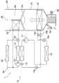
Fig. 1 is an overall configuration diagram of a vehicle air conditioner according to a first embodiment.
Fig. 2 is a block diagram showing a control system of a vehicle air conditioner according to a first embodiment.
Fig. 3 is an explanatory diagram of heat introduction in the first embodiment.
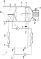
Fig. 4 is a schematic configuration diagram of a vehicle air conditioner according to a second embodiment.
Fig. 5 is an explanatory diagram relating to heat introduction in the second embodiment.
Fig. 6 is a schematic configuration diagram of a vehicular air conditioning system according to a third embodiment.
Fig. 7 is an explanatory diagram relating to heat introduction in the third embodiment.
Fig. 8 is a schematic configuration diagram of a vehicle air conditioner according to a fourth embodiment.
Fig. 9 is an explanatory diagram relating to heat introduction in the fourth embodiment.
Fig. 10 is a schematic configuration diagram of a vehicle air conditioner according to a fifth embodiment.
Fig. 11 is a schematic configuration diagram of a vehicular air conditioning system according to a sixth embodiment.
Fig. 12 is an explanatory view showing a modification of the heating heat absorber constituting the refrigeration cycle apparatus of the present invention.
Detailed Description
Hereinafter, embodiments of the present invention will be described with reference to the drawings. In the following embodiments, the same or corresponding portions are denoted by the same reference numerals in the drawings.
(first embodiment)
First, a first embodiment of the present invention will be described with reference to fig. 1 to 3. The refrigeration cycle device 10 of the first embodiment is applied to a vehicle air conditioner 1 mounted on an electric vehicle that obtains a driving force for vehicle running from a running motor.
The refrigeration cycle device 10 has a function of adjusting the temperature of the feed air blown into the vehicle interior as the air-conditioned space in the vehicle air conditioner 1. This air supply corresponds to the fluid to be heat-exchanged in the present invention.
In addition, the vehicle air conditioner 1 can realize a plurality of operation modes by switching the refrigerant circuit according to the operation mode. The plurality of operation modes include a cooling mode, a heating mode, a dehumidification and heating mode, and the like.
The cooling mode is an operation mode for cooling the air to cool the vehicle interior, and is an example of the cooling mode in the present invention. The heating mode is an operation mode in which the air is heated to heat the vehicle interior, and is an example of the heating mode in the present invention. The dehumidification and heating mode is an operation mode in which the cooled and dehumidified supply air is reheated to perform dehumidification and heating in the vehicle interior, and is an example of the heating mode in the present invention.
In the refrigeration cycle apparatus 10, an HFC-based refrigerant (specifically, R134a) is used as the refrigerant, and a subcritical refrigeration cycle in which the high-pressure side refrigerant pressure does not exceed the critical pressure of the refrigerant is configured. Refrigerating machine oil for lubricating the compressor 11 is mixed into the refrigerant. As the refrigerating machine oil, PAG oil (polyalkylene glycol oil) compatible with the liquid-phase refrigerant is used. A part of the refrigerating machine oil circulates in the cycle together with the refrigerant.
Next, a specific configuration of the vehicle air conditioner 1 according to the first embodiment will be described with reference to fig. 1. First, each constituent device constituting the refrigeration cycle device 10 in the vehicle air conditioner 1 will be described.
The compressor 11 sucks, compresses, and discharges a refrigerant in the refrigeration cycle apparatus 10, and corresponds to a compressor of the present invention. The compressor 11 is disposed in a vehicle hood. The compressor 11 is an electric compressor in which a fixed displacement type compression mechanism having a fixed discharge displacement is rotationally driven by a motor. The compressor 11 controls the rotation speed (i.e., the refrigerant discharge capacity) by a control signal output from an air conditioning control device 60 described later.
The discharge port of the compressor 11 is connected to the inlet side of the refrigerant passage of the high-temperature-side water-refrigerant heat exchanger 12. The high-temperature-side water-refrigerant heat exchanger 12 is a heat exchanger that heats a high-temperature-side heat medium by exchanging heat between the high-pressure refrigerant discharged from the compressor 11 and the high-temperature-side heat medium circulating in the high-temperature-side heat medium circuit 20. As the high-temperature side heat medium, a solution containing ethylene glycol, an antifreeze, or the like can be used.
Here, the high-temperature-side heat medium circuit 20 is a high-temperature-side water circuit through which a high-temperature-side heat medium circulates. In the high-temperature-side heat medium circuit 20, a water passage of the high-temperature-side water-refrigerant heat exchanger 12, a high-temperature-side heat medium pump 21, a heater core 22, a high-temperature-side radiator 23, a high-temperature-side flow rate adjustment valve 24, and the like are arranged.
The high-temperature-side heat medium pump 21 is a high-temperature-side water pump that pumps the high-temperature-side heat medium in the high-temperature-side heat medium circuit 20 to the inlet side of the water passage of the high-temperature-side water-refrigerant heat exchanger 12. The high-temperature-side heat medium pump 21 is an electric pump whose rotation speed (i.e., hydraulic pressure transmission capacity) is controlled by a control voltage output from the air conditioning control device 60.
The heater core 22 is disposed in a casing 51 of the indoor air conditioning unit 50 described later. The heater core 22 is a heat exchanger that heats the feed air by exchanging heat between the high-temperature-side heat medium heated in the high-temperature-side water-refrigerant heat exchanger 12 and the feed air passing through the indoor evaporator 16, which will be described later. The heater core 22 corresponds to the heater core according to the present invention.
The high-temperature-side radiator 23 is a heat exchanger that exchanges heat between the high-temperature-side heat medium heated in the high-temperature-side water-refrigerant heat exchanger 12 and the outside air blown from the outside air fan 30, and radiates heat of the high-temperature-side heat medium to the outside air. The high-temperature-side radiator 23 corresponds to the high-temperature-side radiator in the present invention.
The high-temperature-side radiator 23 is disposed on the front side in the vehicle hood. Therefore, even when the vehicle is traveling, the traveling wind can be blown to the high-temperature side radiator 23. As shown in fig. 1, in the high-temperature-side heat medium circuit 20, the heater core 22 and the high-temperature-side radiator 23 are connected in parallel with respect to the flow of the high-temperature-side heat medium.
The high-temperature-side flow rate adjustment valve 24 is composed of an electric three-way flow rate adjustment valve, and is disposed in a connection portion between the heat medium inlet side of the heater core 22 and the heat medium inlet side of the high-temperature-side radiator 23 in the water passage on the outlet side of the high-temperature-side water-refrigerant heat exchanger 12.
More specifically, the inlet side of the high-temperature-side flow rate adjustment valve 24 is connected to the outlet of the water passage of the high-temperature-side water-refrigerant heat exchanger 12. One outlet of the high-temperature-side flow rate adjustment valve 24 is connected to the heat medium inlet side of the heater core 22. The other outlet of high-temperature-side flow rate adjustment valve 24 is connected to the heat medium inlet side of high-temperature-side radiator 23.
Therefore, the high-temperature-side flow rate adjustment valve 24 can continuously adjust the high-temperature-side flow rate ratio between the flow rate of the high-temperature-side heat medium flowing into the heater core 22 and the flow rate of the high-temperature-side heat medium flowing into the high-temperature-side radiator 23, among the high-temperature-side heat media flowing out of the high-temperature-side water-refrigerant heat exchanger 12. The operation of high-temperature-side flow rate adjustment valve 24 is controlled by a control signal output from air conditioning control device 60.
Therefore, in the high-temperature-side heat medium circuit 20, when the high-temperature-side flow rate adjustment valve 24 adjusts the high-temperature-side flow rate ratio, the flow rate of the high-temperature-side heat medium flowing into the heater core 22 changes, and the amount of heat radiation from the high-temperature-side heat medium in the heater core 22 to the feed air changes. That is, the heating amount of the feed air in the heater core 22 can be adjusted by adjusting the high-temperature-side flow rate ratio by the high-temperature-side flow rate adjustment valve 24.
That is, in the first embodiment, the high-temperature-side heat medium pump 21, the high-temperature-side water-refrigerant heat exchanger 12, the heater core 22, the high-temperature-side radiator 23, the high-temperature-side flow rate adjustment valve 24, and the like, which are disposed in the high-temperature-side heat medium circuit 20, heat the air-sending, using the refrigerant discharged from the compressor 11 as a heat source, and therefore these components constitute a heating unit in the present invention.
As shown in fig. 1, a modulator 13 is connected to an outlet of the refrigerant passage of the high-temperature-side water-refrigerant heat exchanger 12. The modulator 13 is a refrigerant storage unit that separates the refrigerant flowing out of the high-temperature-side water-refrigerant heat exchanger 12 into a gas and a liquid, and stores the remaining liquid-phase refrigerant. The modulator 13 is connected to a refrigerant inlet side of a branch portion 14 a.
The branch portion 14a branches the flow of the high-pressure refrigerant flowing out of the refrigerant passages of the high-temperature side water-refrigerant heat exchanger 12 and the modulator 13. The branch portion 14a is formed as a three-way joint structure having three refrigerant inflow and outflow ports that communicate with each other, and one of the three inflow and outflow ports is a refrigerant inflow port, and the remaining two are refrigerant outflow ports.
One refrigerant outlet of the branch portion 14a is connected to a refrigerant inlet side of the indoor evaporator 16 via a cooling expansion valve 15 a. The other refrigerant outlet of the branch portion 14a is connected to the refrigerant inlet side of the outdoor evaporator 18 via the heat-absorbing expansion valve 15 b. Therefore, the branch portion 14a corresponds to a branch portion in the present invention.
The cooling expansion valve 15a is a cooling decompression portion that decompresses the refrigerant flowing out of one of the refrigerant outlets of the branch portion 14a at least in the cooling mode and the dehumidification and heating mode. The cooling expansion valve 15a corresponds to a cooling decompression section in the present invention. The cooling expansion valve 15a also functions as a cooling flow rate adjustment unit that adjusts the flow rate of the refrigerant flowing into the indoor evaporator 16.
The cooling expansion valve 15a is an electric variable throttle mechanism, and includes a valve element and an electric actuator. That is, the cooling expansion valve 15a is a so-called electric expansion valve. The valve body of the cooling expansion valve 15a is configured to be able to change the passage opening degree (in other words, throttle opening degree) of the refrigerant passage. The electric actuator includes a stepping motor that changes the throttle opening of the valve body.
The operation of the cooling expansion valve 15a is controlled by a control signal output from the air conditioning control device 60. The cooling expansion valve 15a is constituted by a variable throttle mechanism having a fully-open function of fully opening the refrigerant passage when the throttle opening is fully opened and a fully-closed function of closing the refrigerant passage when the throttle opening is fully closed.
That is, the expansion valve for cooling 15a can prevent the refrigerant from being decompressed by fully opening the refrigerant passage. The cooling expansion valve 15a can block the refrigerant from flowing into the indoor evaporator 16 by closing the refrigerant passage. That is, the cooling expansion valve 15a has both a function as a pressure reducing unit for reducing the pressure of the refrigerant and a function as a circuit switching unit for switching the refrigerant circuit.
The outlet of the cooling expansion valve 15a is connected to the refrigerant inlet side of the indoor evaporator 16. The interior evaporator 16 is disposed within a housing 51 of the indoor air conditioning unit 50. The indoor evaporator 16 is a cooling evaporator that exchanges heat between the low-pressure refrigerant decompressed by the cooling expansion valve 15a and the feed air at least in the cooling mode and the dehumidification and heating mode, evaporates the low-pressure refrigerant, and cools the feed air. That is, the indoor evaporator 16 corresponds to a heat absorber for cooling in the present invention.
The refrigerant outlet of the indoor evaporator 16 is connected to the inlet side of an evaporation pressure regulating valve 17. The evaporation pressure adjustment valve 17 is an evaporation pressure adjustment portion that maintains the refrigerant evaporation pressure in the indoor evaporator 16 at a preset reference pressure or higher. The evaporation pressure adjustment valve 17 is constituted by a mechanical variable throttle mechanism that increases the valve opening degree in accordance with the increase in refrigerant pressure on the outlet side of the indoor evaporator 16.
The evaporation pressure adjustment valve 17 is configured to maintain the refrigerant evaporation temperature in the indoor evaporator 16 at a reference temperature (1 ℃ in the present embodiment) or higher at which frost formation in the indoor evaporator 16 can be suppressed.
One refrigerant flow inlet side of the merging portion 14b is connected to an outlet of the evaporation pressure adjustment valve 17. The merging portion 14b has a three-way joint structure similar to the branching portion 14a, and two of the three inflow and outflow ports are refrigerant inflow ports, and the remaining one is a refrigerant outflow port. As shown in fig. 1, the merging portion 14b merges the flow of the refrigerant flowing out of the evaporation pressure adjustment valve 17 with the flow of the refrigerant flowing out of the outdoor evaporator 18.
Here, the heat-absorbing expansion valve 15b is connected to the other refrigerant outflow port of the branch portion 14 a. The heat-absorbing expansion valve 15b is a heat-absorbing decompression portion that decompresses and expands the liquid-phase refrigerant flowing out of the other refrigerant outlet of the branch portion 14a at least in the heating mode and the dehumidification and heating mode. The heat absorption expansion valve 15b functions as a decompression unit for heating in the present invention.
The heat-absorbing expansion valve 15b functions as a heat-absorbing flow rate adjustment unit that adjusts the flow rate of the refrigerant flowing into the outdoor evaporator 18. The basic structure of the expansion valve for heat absorption 15b is the same as that of the expansion valve for cooling 15 a. That is, the heat absorption expansion valve 15b is an electric variable throttle mechanism, and includes a valve body and an electric actuator. The heat absorption expansion valve 15b has a fully open function and a fully closed function, as in the cooling expansion valve 15 a.
That is, the heat-absorbing expansion valve 15b can block the refrigerant from flowing into the outdoor evaporator 18 by closing the refrigerant passage without exerting the function of reducing the pressure of the refrigerant by fully opening the refrigerant passage. That is, the heat-absorbing expansion valve 15b has both a function as a pressure reducing unit for reducing the pressure of the refrigerant and a function as a circuit switching unit for switching the refrigerant circuit.
The refrigerant inlet side of the outdoor evaporator 18 is connected to the outlet of the heat-absorbing expansion valve 15 b. The outdoor evaporator 18 is a heat absorption evaporator that exchanges heat between the low-pressure refrigerant decompressed by the heat absorption expansion valve 15b and the outdoor air blown from the outdoor air fan 30 in at least the heating mode and the dehumidification and heating mode, evaporates the low-pressure refrigerant, and causes the refrigerant to absorb heat. The outdoor evaporator 18 functions as a heat absorber for heating in the present invention, and the outside air functions as a heat source fluid.
The outdoor evaporator 18 is disposed on the front side in the vehicle hood. The refrigerant outlet of the outdoor evaporator 18 is connected to the other refrigerant inlet side of the merging portion 14 b. The refrigerant outlet of the merging portion 14b is connected to the suction port of the compressor 11.
Next, the indoor air conditioning unit 50 constituting the air conditioning device 1 for a vehicle will be described. The indoor air conditioning unit 50 is formed in the vehicle air conditioning device 1 with an air passage for blowing out the supply air whose temperature has been adjusted by the refrigeration cycle device 10 to an appropriate location in the vehicle interior. The indoor air conditioning unit 50 is disposed inside an instrument panel (i.e., an instrument panel) at the forefront in the vehicle interior.
The indoor air conditioning unit 50 is configured to accommodate a blower 52, the indoor evaporator 16, the heater core 22, and the like in an air passage formed inside a casing 51 forming an outer shell thereof. The casing 51 forms an air passage for blowing air into the vehicle interior, and is molded from a resin (specifically, polypropylene) having a certain degree of elasticity and excellent strength.
As shown in fig. 1, an inside/outside air switching device 53 is disposed on the most upstream side of the flow of the blast air in the casing 51. The inside/outside air switching device 53 switches and introduces inside air (vehicle interior air) and outside air (vehicle exterior air) into the casing 51.
The inside/outside air switching device 53 can change the ratio of the amount of the inside air introduced to the outside air introduced to the inside air by continuously adjusting the opening areas of the inside air inlet for introducing the inside air and the outside air inlet for introducing the outside air into the casing 51 by the inside/outside air switching door. The inside and outside air switching door is driven by an electric actuator for the inside and outside air switching door. The operation of the electric actuator is controlled by a control signal output from the air conditioning control device 60.
A blower 52 is disposed on the downstream side of the blowing air flow of the inside/outside air switching device 53. The blower 52 is composed of an electric blower in which a centrifugal sirocco fan is driven by a motor, and functions to blow air sucked through the inside/outside air switching device 53 into the vehicle interior. The air blown by the blower 52 corresponds to the fluid to be heat-exchanged in the present invention. The blower 52 controls the rotation speed (i.e., blowing capacity) by a control voltage output from the air conditioning control device 60.
The indoor evaporator 16 and the heater core 22 are disposed in this order with respect to the flow of the supply air on the downstream side of the flow of the supply air of the blower 52. That is, the indoor evaporator 16 is disposed on the upstream side of the heater core 22 with respect to the flow of the blowing air.
Further, a cool air bypass passage 55 is formed in the housing 51, and the cool air bypass passage 55 allows the supply air passing through the indoor evaporator 16 to flow on the downstream side while bypassing the heater core 22.
An air mix door 54 is disposed on the downstream side of the indoor evaporator 16 in the flow of the blowing air and on the upstream side of the heater core 22 in the flow of the blowing air. The air mix door 54 adjusts the air volume ratio of the air volume passing through the heater core 22 to the air volume passing through the cool air bypass passage 55 in the feed air passing through the indoor evaporator 16.
The air mix door 54 is driven by an electric actuator for driving the air mix door. The operation of the electric actuator is controlled by a control signal output from the air conditioning control device 60.
A mixing space 56 is provided on the downstream side of the flow of the blowing air of the heater core 22, and the mixing space 56 mixes the blowing air heated by the heater core 22 with the blowing air passing through the cool-air bypass passage 55 and not heated by the heater core 22. Further, an opening hole for blowing out the feed air (air-conditioned air) mixed in the mixing space into the vehicle interior is disposed in the most downstream portion of the feed air flow of the casing 51.
The opening holes include a face opening hole, a foot opening hole, and a defroster opening hole (none of which are shown). The face opening hole is an opening hole for blowing out the air-conditioning air toward the upper body of the occupant in the vehicle compartment. The foot opening hole is an opening hole for blowing out the air conditioning air to the underside of the foot of the occupant. The defroster opening hole is an opening hole for blowing out the air-conditioned air toward the inner side surface of the window glass of the front surface of the vehicle.
The face opening hole, the foot opening hole, and the defroster opening hole are connected to a face air outlet, a foot air outlet, and a defroster air outlet (all not shown) provided in the vehicle interior via ducts forming air passages, respectively.
Therefore, the air mix door 54 adjusts the air volume ratio of the air volume passing through the heater core 22 to the air volume passing through the cool air bypass passage 55, thereby adjusting the temperature of the conditioned air mixed in the mixing space. Thereby, the temperature of the feed air (air-conditioned air) blown out into the vehicle interior from each air outlet is also adjusted.
A face door for adjusting the opening area of the face opening hole, a foot door for adjusting the opening area of the foot opening hole, and a defroster door for adjusting the opening area of the defroster opening hole are disposed on the upstream side of the blowing air flow of the face opening hole, the foot opening hole, and the defroster opening hole, respectively (none of which are shown).
These face door, foot door, and defroster door constitute a blow-out mode switching device that switches the blow-out port from which the conditioned air is blown out. The face door, foot door, and defroster door are linked to and rotationally operated in conjunction with an electric actuator for driving the outlet mode door via a link mechanism or the like. The operation of the electric actuator is controlled by a control signal output from air conditioning control device 60.
Next, a control system of the vehicle air conditioner 1 according to the first embodiment will be described with reference to fig. 2. The air conditioning control device 60 is constituted by a known microcomputer including a CPU, a ROM, a RAM, and the like, and peripheral circuits thereof.
The air conditioning control device 60 performs various calculations and processes based on an air conditioning control program stored in its ROM, and controls the operation of various control target devices connected to its output side. The control target devices according to the first embodiment include the compressor 11, the cooling expansion valve 15a, the heat absorption expansion valve 15b, the high-temperature-side heat medium pump 21, the high-temperature-side flow rate adjustment valve 24, the outside air fan 30, the blower 52, and the like.
As shown in fig. 2, a sensor group for air conditioning control, such as an inside air temperature sensor 62a, an outside air temperature sensor 62b, a solar radiation sensor 62c, a high pressure sensor 62d, an evaporator temperature sensor 62e, an air conditioning air temperature sensor 62f, and an outlet side temperature sensor 62g, is connected to the input side of the air conditioning control device 60. Detection signals of these air conditioning control sensor groups are input to the air conditioning control device 60.
The interior air temperature sensor 62a is an interior air temperature detecting unit that detects a vehicle interior temperature (interior air temperature) Tr. The outside air temperature sensor 62b is an outside air temperature detecting unit that detects a vehicle outside temperature (outside air temperature) Tam. The solar radiation sensor 62c is a solar radiation amount detection unit that detects the amount of solar radiation As irradiated into the vehicle interior. The high-pressure sensor 62d is a refrigerant pressure detection unit that detects a high-pressure refrigerant pressure Pd in a refrigerant passage from the discharge port side of the compressor 11 to the inlet side of the cooling expansion valve 15a or the heat absorption expansion valve 15 b.
The evaporator temperature sensor 62e is an evaporator temperature detecting portion that detects a refrigerant evaporation temperature (evaporator temperature) Tefin in the indoor evaporator 16. The air-conditioning air temperature sensor 62f is an air-conditioning air temperature detecting unit that detects the temperature TAV of the supply air blown into the vehicle interior. The outlet-side temperature sensor 62g is an outlet-side temperature detecting unit that detects an outlet-side temperature Te of the refrigerant on the outlet side of the outdoor evaporator 18.
Further, an operation panel 61 disposed near an instrument panel in the front part of the vehicle interior is connected to the input side of the air conditioning control device 60. Therefore, operation signals from various operation switches provided on the operation panel 61 are input to the air conditioning control device 60.
Specifically, the various operation switches provided on the operation panel 61 include an automatic switch for setting or releasing an automatic control operation of the vehicle air conditioner 1, a cooling switch for requesting cooling of the vehicle interior, an air volume setting switch for manually setting the air volume of the blower 52, and a temperature setting switch for setting a target temperature Tset in the vehicle interior.
Further, in the air conditioning control device 60, a control unit that controls various control target devices connected to the output side of the air conditioning control device 60 is integrally configured, but a configuration (hardware and software) that controls the operation of each control target device constitutes a control unit that controls the operation of each control target device.
For example, in the air conditioning control device 60, the configuration for controlling the operation of the compressor 11 is the discharge capacity control unit 60 a. In the air conditioning control device 60, a circuit switching control unit 60b is configured to control the operations of the cooling expansion valve 15a and the heat absorption expansion valve 15b as a circuit switching unit. Further, in the air conditioning control device 60, a frost formation determination unit 60c is provided for determining the risk of frost formation in the outdoor evaporator 18.
Specifically, when the outlet-side temperature Te detected by the outlet-side temperature sensor 62g is lower than a value obtained by subtracting the preset reference temperature α from the outside air temperature Tam detected by the outside air temperature sensor, the frost formation determination unit 60c determines that there is a risk of frost formation in the outdoor evaporator 18.
Next, the operation of the vehicle air conditioner 1 according to the first embodiment will be described. As described above, in the vehicular air conditioning device 1 according to the first embodiment, the operation mode can be appropriately switched from the plurality of operation modes. These operation modes are switched by executing an air conditioning control program stored in advance in air conditioning control device 60.
More specifically, in the air conditioning control program, the target outlet temperature TAO of the blast air to be blown into the vehicle interior is calculated based on the detection signal detected by the sensor group for air conditioning control and the operation signal output from the operation panel 61. Then, the operation mode is switched according to the target outlet air temperature TAO and the detection signal. Hereinafter, an operation in the cooling mode and an operation in the heating mode among the plurality of operation modes will be described.
(a) Refrigeration mode
The cooling mode is an operation mode for cooling the air to be blown as the fluid to be heat-exchanged and blowing the air into the vehicle interior, and is an example of the cooling mode in the present invention. In this cooling mode, the air conditioning control device 60 opens the cooling expansion valve 15a at a predetermined throttle opening degree, and completely closes the heat absorption expansion valve 15 b.
Therefore, in the refrigeration cycle device 10 in the cooling mode, a vapor compression refrigeration cycle is configured in which the refrigerant circulates in the order of the compressor 11 → the high-temperature side water-refrigerant heat exchanger 12 → the modulator 13 → the branching portion 14a → the expansion valve 15a for cooling → the indoor evaporator 16 → the evaporation pressure adjustment valve 17 → the merging portion 14b → the compressor 11.
That is, in the cooling mode, the refrigerant is caused to flow into the indoor evaporator 16, and is switched to the refrigerant circuit that cools the feed air by heat exchange with the feed air.
In this cycle configuration, air conditioning control device 60 controls the operation of various devices to be controlled connected to the output side.
For example, the air conditioning control device 60 controls the operation of the compressor 11 so that the refrigerant evaporation temperature Tefin detected by the evaporator temperature sensor 62e becomes the target evaporation temperature TEO. The target evaporation temperature TEO is determined based on the target outlet air temperature TAO, with reference to a control map for the cooling mode, which is stored in advance in the air conditioning control device 60.
Specifically, in the control map, the target evaporation temperature TEO is increased so that the feed air temperature TAV detected by the air-conditioning air temperature sensor 62f approaches the target outlet air temperature TAO as the target outlet air temperature TAO increases. Further, the target evaporation temperature TEO is determined to be a value in a range (specifically, 1 ℃ or higher) in which the frost formation of the indoor evaporator 16 can be suppressed.
The air conditioning control device 60 operates the high-temperature-side heat medium pump 21 so as to exhibit the water pressure delivery capacity in the predetermined cooling mode. The air conditioning control device 60 controls the operation of the high temperature side flow rate adjustment valve 24 so that the entire flow rate of the high temperature side heat medium flowing out of the water passage of the high temperature side water-refrigerant heat exchanger 12 flows into the high temperature side radiator 23.
Then, the air conditioning control device 60 determines the control voltage (blowing capacity) of the blower 52 based on the target outlet air temperature TAO with reference to a control map stored in advance in the air conditioning control device 60. Specifically, in the control map, the blowing amount of the blower 52 is maximized in the extremely low temperature region (maximum cooling region) and the extremely high temperature region (maximum heating region) of the target outlet air temperature TAO, and the blowing amount is decreased as the temperature approaches the intermediate temperature region.
The air conditioning controller 60 controls the operation of the air mix door 54 so that the cool air bypass passage 55 is fully opened to close the ventilation passage on the heater core 22 side. The air conditioning control device 60 also appropriately controls the operation of various other devices to be controlled.
Therefore, in the refrigeration cycle device 10 in the cooling mode, the high-pressure refrigerant discharged from the compressor 11 flows into the high-temperature-side water-refrigerant heat exchanger 12. In the high-temperature-side water-refrigerant heat exchanger 12, since the high-temperature-side heat medium pump 21 is operated, the high-pressure refrigerant exchanges heat with the high-temperature-side heat medium, the high-pressure refrigerant is cooled and condensed, and the high-temperature-side heat medium is heated.
In the high-temperature-side heat medium circuit 20, the high-temperature-side heat medium heated in the high-temperature-side water-refrigerant heat exchanger 12 flows into the high-temperature-side radiator 23 via the high-temperature-side flow rate adjustment valve 24. The high-temperature-side heat medium flowing into the high-temperature-side radiator 23 exchanges heat with outside air to dissipate heat. Thereby, the high-temperature-side heat medium is cooled. The high-temperature-side heat medium cooled by the high-temperature-side radiator 23 is sucked into the high-temperature-side heat medium pump 21, and is pressure-fed again into the water passage of the high-temperature-side water-refrigerant heat exchanger 12.
The high-pressure refrigerant cooled in the refrigerant passage of the high-temperature-side water-refrigerant heat exchanger 12 flows into the cooling expansion valve 15a via the branch portion 14a and is decompressed. The throttle opening degree of the cooling expansion valve 15a is adjusted so that the degree of superheat of the refrigerant on the outlet side of the indoor evaporator 16 becomes substantially 3 ℃.
The low-pressure refrigerant decompressed by the cooling expansion valve 15a flows into the indoor evaporator 16. The refrigerant flowing into the indoor evaporator 16 absorbs heat from the air blown by the blower fan 52 and evaporates. Thereby, the air to be blown as the fluid to be heat-exchanged is cooled. The refrigerant flowing out of the indoor evaporator 16 is sucked into the compressor 11 via the evaporation pressure adjustment valve 17 and the merging portion 14b and is compressed again.
Therefore, in the cooling mode, the air cooled by the interior evaporator 16 is blown into the vehicle interior, thereby cooling the vehicle interior.
(b) Heating mode
The heating mode is an operation mode in which the outdoor evaporator 18 absorbs heat from outside air as a heat source fluid and heats and blows air as a heat exchange target fluid into the vehicle interior, and is an example of the heating mode in the present invention. In the heating mode, the air conditioning control device 60 completely closes the cooling expansion valve 15a, and opens the heat absorption expansion valve 15b at a predetermined throttle opening.
Therefore, in the refrigeration cycle device 10 of the heating mode, a vapor compression refrigeration cycle is configured in which the refrigerant circulates in the order of the compressor 11 → the high-temperature-side water-refrigerant heat exchanger 12 → the modulator 13 → the branch portion 14a → the heat-absorbing expansion valve 15b → the outdoor evaporator 18 → the junction portion 14b → the compressor 11.
That is, in the heating mode, the following refrigerant circuits are switched: the refrigerant flows into the outdoor evaporator 18, and heats the air by heat absorbed by heat exchange with the outside air.
In this cycle configuration, air conditioning control device 60 controls the operation of various devices to be controlled connected to the output side.
For example, the air conditioning control device 60 controls the operation of the compressor 11 so that the high-pressure refrigerant pressure Pd detected by the high-pressure sensor 62d becomes the target high-pressure PCO. The target high pressure PCO is determined based on the target outlet air temperature TAO with reference to a control map for the heating mode stored in advance in the air conditioning control device 60.
Specifically, in the control map, the target high pressure PCO is increased so that the feed air temperature TAV approaches the target outlet temperature TAO as the target outlet temperature TAO increases.
The air conditioning control device 60 operates the high-temperature-side heat medium pump 21 so as to exhibit a water pressure feed capacity in the heating mode set in advance. The air conditioning control device 60 controls the operation of the high temperature side flow rate adjustment valve 24 so that the entire flow rate of the high temperature side heat medium flowing out of the water passage of the high temperature side water-refrigerant heat exchanger 12 flows into the heater core 22.
Then, the air conditioning control device 60 determines the control voltage (blowing capacity) of the blower 52 in the same manner as in the cooling mode. The air conditioning control device 60 controls the operation of the air mix door 54 so that the ventilation passage on the heater core 22 side is fully opened to close the cool air bypass passage 55. Further, air conditioning control device 60 also appropriately controls the operation of various other devices to be controlled.
Therefore, in the refrigeration cycle device 10 of the heating mode, the high-pressure refrigerant discharged from the compressor 11 flows into the high-temperature-side water-refrigerant heat exchanger 12. In the high-temperature-side water-refrigerant heat exchanger 12, since the high-temperature-side heat medium pump 21 is operated, the high-pressure refrigerant exchanges heat with the high-temperature-side heat medium, the high-pressure refrigerant is cooled and condensed, and the high-temperature-side heat medium is heated.
In the high-temperature-side heat medium circuit 20, the high-temperature-side heat medium heated by the high-temperature-side water-refrigerant heat exchanger 12 flows into the heater core 22 via the high-temperature-side flow rate adjustment valve 24. Since the air mix door 54 fully opens the ventilation path on the heater core 22 side, the high-temperature-side heat medium flowing into the heater core 22 exchanges heat with the supply air passing through the indoor evaporator 16 to dissipate heat.
Thereby, the feed air as the heat exchange target fluid is heated, and the temperature of the feed air approaches the target outlet temperature TAO. The high-temperature-side heat medium flowing out of the heater core 22 is sucked into the high-temperature-side heat medium pump 21 and pressure-fed into the water passage of the high-temperature-side water-refrigerant heat exchanger 12 again.
The high-pressure refrigerant flowing out of the refrigerant passage of the high-temperature side water-refrigerant heat exchanger 12 flows into the heat-absorbing expansion valve 15b via the branch portion 14a and is decompressed. The throttle opening degree of the heat-absorbing expansion valve 15b is adjusted so that the refrigerant on the outlet side of the outdoor evaporator 18 is in a gas-liquid two-phase state.
The low-pressure refrigerant decompressed by the heat-absorbing expansion valve 15b flows into the outdoor evaporator 18. The refrigerant flowing into the outdoor evaporator 18 absorbs heat from the outside air, which is the heat source fluid blown from the outside air fan 30, and evaporates. The refrigerant flowing out of the outdoor evaporator 18 is sucked into the compressor 11 via the merging portion 14b and compressed again.
Therefore, in the heating mode, the heater core 22 heats the blowing air as the fluid to be heat-exchanged and blows the heated blowing air into the vehicle interior, thereby heating the vehicle interior.
(c) Dehumidification heating mode
The dehumidification and heating mode is an operation mode in which the outdoor evaporator 18 heats the blown air, which is the fluid to be heat-exchanged and is cooled by the indoor evaporator 16, by using heat absorbed from the outside air, which is the heat source fluid, and blows the heated blown air into the vehicle interior, and is an example of the heating mode in the present invention. In the dehumidification and heating mode, the air conditioning control device 60 opens the cooling expansion valve 15a and the heat absorption expansion valve 15b at predetermined throttle openings.
Therefore, in the refrigeration cycle apparatus 10 in the dehumidification-heating mode, the refrigerant flows and circulates in the following order: flows into the compressor 11 → the high-temperature-side water-refrigerant heat exchanger 12 → the modulator 13 → the branch portion 14a, flows into one side of the branch portion 14a → the expansion valve for cooling 15a → the indoor evaporator 16, and flows into the other side of the branch portion 14a → the expansion valve for heat absorption 15b → the outdoor evaporator 18. The refrigerant flowing out of the indoor evaporator 16 and the refrigerant flowing out of the outdoor evaporator 18 are merged at the merging portion 14b and then flow to the compressor 11. That is, in the dehumidification and heating mode, a vapor compression refrigeration cycle is configured in which the refrigerant flows in parallel into the indoor evaporator 16 and the outdoor evaporator 18.
In this cycle configuration, air-conditioning control device 60 refers to a control map for the dehumidification and heating mode stored in advance in air-conditioning control device 60, and controls the operation of various devices to be controlled connected to the output side.
In the refrigeration cycle apparatus 10 in the dehumidification-heating mode, the high-pressure refrigerant discharged from the compressor 11 flows into the high-temperature-side water-refrigerant heat exchanger 12. In the high-temperature-side water-refrigerant heat exchanger 12, since the high-temperature-side heat medium pump 21 is operated, the high-pressure refrigerant exchanges heat with the high-temperature-side heat medium, the high-pressure refrigerant is cooled and condensed, and the high-temperature-side heat medium is heated.
In the high-temperature-side heat medium circuit 20, the high-temperature-side heat medium heated in the high-temperature-side water-refrigerant heat exchanger 12 flows into the heater core 22 via the high-temperature-side flow rate adjustment valve 24. Since the air mix door 54 fully opens the ventilation path on the heater core 22 side, the high-temperature-side heat medium flowing into the heater core 22 exchanges heat with the supply air cooled by the indoor evaporator 16 to dissipate heat.
Thereby, the feed air as the heat exchange target fluid is reheated from the cooled state, and the temperature of the feed air approaches the target outlet temperature TAO. The high-temperature-side heat medium flowing out of the heater core 22 is sucked into the high-temperature-side heat medium pump 21 and pressure-fed into the water passage of the high-temperature-side water-refrigerant heat exchanger 12 again.
The high-pressure refrigerant flowing out of the refrigerant passage of the high-temperature side water-refrigerant heat exchanger 12 flows into the cooling expansion valve 15a via the branch portion 14a and is reduced in pressure. The throttle opening degree of the cooling expansion valve 15a is adjusted so that the degree of superheat of the refrigerant on the outlet side of the indoor evaporator 16 becomes substantially 3 ℃.
The low-pressure refrigerant decompressed by the cooling expansion valve 15a flows into the indoor evaporator 16. The refrigerant flowing into the indoor evaporator 16 absorbs heat from the air blown by the blower fan 52 and evaporates. Thereby, the air to be blown as the fluid to be heat-exchanged is cooled. The refrigerant flowing out of the indoor evaporator 16 is sucked into the compressor 11 via the evaporation pressure adjustment valve 17 and the merging portion 14b and is compressed again.
The high-pressure refrigerant branched at the branch portion 14a flows into the heat-absorbing expansion valve 15b and is decompressed. The throttle opening degree of the heat-absorbing expansion valve 15b is adjusted so that the refrigerant on the outlet side of the outdoor evaporator 18 is in a gas-liquid two-phase state.
The low-pressure refrigerant decompressed by the heat-absorbing expansion valve 15b flows into the outdoor evaporator 18. The refrigerant flowing into the outdoor evaporator 18 absorbs heat from the outside air, which is the heat source fluid blown from the outside air fan 30, and evaporates. The refrigerant flowing out of the outdoor evaporator 18 merges with the refrigerant having passed through the indoor evaporator 16 and the evaporation pressure adjustment valve 17 at the merging portion 14b, and is sucked into and compressed again by the compressor 11.
As described above, since the heater core 22 is disposed inside the casing 51 on the downstream side of the flow of the air blown by the indoor evaporator 16, the air blown by the indoor evaporator 16 after being cooled can be heated by the heater core 22 using the heat absorbed by the outdoor evaporator 18 in the dehumidification and heating mode.
As described above, according to the vehicle air conditioning apparatus 1 of the first embodiment, the refrigeration cycle apparatus 10 can switch the refrigerant circuit to switch the cooling mode, the heating mode, and the dehumidification and heating mode among the plurality of operation modes, and comfortable air conditioning in the vehicle interior can be achieved.
Here, in the refrigeration cycle apparatus 10 in which the refrigerant circuit is switched according to the operation mode, the cycle configuration is likely to be complicated. In contrast, in the refrigeration cycle apparatus 10 according to the first embodiment, the refrigerant circuit into which the high-pressure refrigerant flows and the refrigerant circuit into which the low-pressure refrigerant flows are not switched between the same heat exchanger.
That is, no matter which refrigerant circuit is switched to, it is not necessary to cause the high-pressure refrigerant to flow into the indoor evaporator 16 and the outdoor evaporator 18, and therefore, the refrigerant circuits can be switched with a simple configuration without complicating the cycle configuration.
However, in the heating mode and the dehumidification and heating mode, the refrigerant evaporation temperature in the outdoor evaporator 18 may be lower than the outside air temperature. Therefore, in the heating mode or the like, frost formation may occur in the outdoor evaporator 18. When frost formation occurs, the heat exchange performance in the outdoor evaporator 18 is lowered, and thus the heating performance of the vehicle air conditioner 1 is lowered.
As a configuration corresponding to such frosting of the outdoor evaporator 18, it is known to introduce a high-pressure refrigerant into the outdoor evaporator 18 and defrost the outdoor evaporator with the heat of the introduced high-pressure refrigerant. However, in order to introduce the high-pressure refrigerant into the outdoor evaporator 18, a switching valve or the like needs to be added to the refrigeration cycle apparatus 10, which complicates the cycle structure.
In addition, in a configuration in which the operation such as the heating mode is simply stopped, frost can be melted by the outside air while suppressing the progress of frost formation in the outdoor evaporator 18. In this case, since the operation in the heating mode or the like is stopped, the comfort in the vehicle interior is impaired. In addition, since defrosting is performed due to a temperature difference from the outside air temperature, it is assumed that a long time is required until defrosting is completed.
Here, in the refrigeration cycle apparatus 10 of the first embodiment, in order to eliminate the problem caused by the frost formation of the outdoor evaporator 18, the structure shown in fig. 3 is adopted, and the frost formation and the defrosting in the outdoor evaporator 18 are realized by utilizing a part of the heat radiated on the cycle high-pressure side.
Specifically, as shown in fig. 3, the heat exchange portion of the outdoor evaporator 18 is connected to the heat exchange portion of the high-temperature-side radiator 23 in the high-temperature-side heat medium circuit 20 by a plurality of heat transfer fins 31 having thermal conductivity.
The heat transfer fins 31 are configured by sharing a part of the components (for example, heat exchange fins) of the outdoor evaporator 18 or the high-temperature-side radiator 23, and are formed using a metal capable of transferring heat. The heat transfer fins 31 correspond to the heat transfer member in the present invention.
That is, the outdoor evaporator 18 and the high-temperature-side radiator 23 are thermally connected by the plurality of heat transfer fins 31, and are configured to be able to transfer heat radiated from the high-temperature-side radiator 23 to the outdoor evaporator 18.
The heat transfer member in the present invention is not limited to the heat transfer fin 31 configured by sharing the heat exchange fin. As the heat transfer member, various configurations may be employed as long as heat can be transferred from the high-temperature-side radiator 23 to the outdoor evaporator 18, and a separate member having thermal conductivity may be employed instead of sharing the constituent members of the outdoor evaporator 18 and the high-temperature-side radiator 23.
With such a configuration, in the refrigeration cycle apparatus 10, heat radiated from the high-temperature-side radiator 23 can be transferred to the low-temperature-side outdoor evaporator 18. As a result, according to the refrigeration cycle apparatus 10, when the heating mode, the dehumidification and heating mode, and the like are executed, it is possible to suppress the progress of frost formation in the outdoor evaporator 18 or to perform defrosting of the outdoor evaporator 18.
Further, by controlling the operation of the high-temperature-side flow rate adjustment valve 24, the control may be performed to change the balance between the heater core 22 side and the high-temperature-side radiator 23 side with respect to the flow rate of the high-temperature-side heat medium in the high-temperature-side heat medium circuit 20.
For example, when defrosting of the outdoor evaporator 18 is required, the flow rate of the high-temperature-side heat medium to the high-temperature-side radiator 23 side is increased as compared to the heater core 22 side. Accordingly, more heat is transferred from the high-temperature-side radiator 23 to the outdoor evaporator 18 via the heat transfer fins 31, and therefore defrosting of the outdoor evaporator 18 can be performed quickly.
In addition, when the frost formation of the outdoor evaporator 18 is suppressed, the flow rate of the high-temperature-side heat medium toward the high-temperature-side radiator 23 is controlled to be smaller than that toward the heater core 22. This can suppress the frost formation of the outdoor evaporator 18 while maintaining the heating capability of the heater core 22 for the feed air as much as possible.
In the case of the configuration shown in fig. 3, it is not necessary to introduce the high-pressure refrigerant into the outdoor evaporator 18 in order to defrost the outdoor evaporator 18 or the like, and it is not necessary to stop the operation in the heating mode or the like. That is, according to the refrigeration cycle apparatus 10, it is possible to suppress or eliminate the occurrence of a problem due to frost formation of the outdoor evaporator 18 while maintaining comfort in the vehicle interior, which is the air-conditioned space, with a simple cycle configuration.
As described above, according to the refrigeration cycle apparatus 10 of the first embodiment, the refrigerant circuit on the side of the indoor evaporator 16 and the refrigerant circuit on the side of the outdoor evaporator 18 connected to the branch portion 14a can be switched by the circuit switching controller 60 b.
Specifically, according to the refrigeration cycle apparatus 10, in the cooling mode, which is an example of the cooling mode, the refrigerant decompressed by the cooling expansion valve 15a can exchange heat in the indoor evaporator 16, and the air to be blown as the heat exchange target fluid can be cooled.
In the refrigeration cycle apparatus 10, in the heating mode, which is an example of the heating mode, the refrigerant decompressed by the heat absorption expansion valve 15b is caused to exchange heat with the outside air, which is the heat source fluid, in the outdoor evaporator 18, and thereby the air can be heated by using the outside air as the heat source.
In addition, according to the refrigeration cycle apparatus 10, in the dehumidification and heating mode, which is an example of the heating mode, the refrigerant decompressed by the heat absorption expansion valve 15b is subjected to heat exchange with the outside air, which is the heat source fluid, in the outdoor evaporator 18, and thereby the air after being cooled in the indoor evaporator 16 can be heated using the outside air as the heat source.
According to the refrigeration cycle apparatus 10, in any case of which refrigerant circuit is switched, since it is not necessary to cause the high-pressure refrigerant to flow into the indoor evaporator 16 and the outdoor evaporator 18, the refrigerant circuit can be switched with a simple configuration without complicating the cycle configuration. That is, the refrigeration cycle apparatus 10 can realize a plurality of operation modes including a cooling mode, a heating mode, and a dehumidification and heating mode without complicating the cycle configuration.
In this cooling mode, the heat absorbed by the indoor evaporator 16 is radiated to the outside air by the high-temperature-side radiator 23 of the high-temperature-side heat medium circuit 20 constituting the heating unit. That is, the outdoor evaporator 18 does not function as a radiator but functions as a heat absorber. In other words, in the cooling mode of the refrigeration cycle device 10, the high-pressure refrigerant is not caused to flow into the outdoor evaporator 18.
The refrigeration cycle device 10 of the first embodiment includes the high-temperature-side water-refrigerant heat exchanger 12, and a heater core 22 is disposed in the high-temperature-side heat medium circuit 20 through which the high-temperature-side heat medium circulates. Therefore, during the heating mode or the like, the high-temperature-side heat medium heated in the high-temperature-side water-refrigerant heat exchanger 12 can be caused to flow into the heater core 22, thereby heating the feed air.
In the refrigeration cycle device 10 according to the first embodiment, the high-temperature-side radiator 23 is disposed in the high-temperature-side heat medium circuit 20. Therefore, the heat absorbed by the indoor evaporator 16 or the outdoor evaporator 18 can be dissipated to the outside air, and the vehicle interior can be cooled appropriately in the cooling mode.
In the first embodiment, the outdoor evaporator 18 is thermally connected to the high-temperature-side radiator 23, and the heat of the high-temperature-side heat medium in the high-temperature-side heat medium circuit 20 can be transferred to the outdoor evaporator 18.
Specifically, as shown in fig. 3, the heat exchange portion of the outdoor evaporator 18 and the heat exchange portion of the high-temperature-side radiator 23 are connected by a plurality of heat transfer fins 31. Thus, the heat radiated from the high-temperature-side radiator 23 can be transmitted to the outdoor evaporator 18 via the plurality of heat transfer fins 31, and therefore, the progress of frost formation in the outdoor evaporator 18 can be suppressed, or the defrosting of the outdoor evaporator 18 can be performed.
(second embodiment)
Next, a second embodiment different from the first embodiment described above will be described with reference to fig. 4. In fig. 4, the same or corresponding portions as those of the first embodiment are denoted by the same reference numerals. This is also true in the following figures.
The refrigeration cycle device 10 of the second embodiment is applied to the vehicle air conditioner 1 mounted on the electric vehicle, and functions to adjust the temperature of the feed air to be blown into the vehicle interior as the air-conditioned space, as in the first embodiment.
As shown in fig. 4, the vehicle air conditioning device 1 of the second embodiment includes a refrigeration cycle device 10, a high-temperature side heat medium circuit 20, and an indoor air conditioning unit 50, as in the first embodiment.
The high-temperature-side heat medium circuit 20 and the indoor air conditioning unit 50 in the second embodiment have the same configurations as those in the first embodiment. Therefore, description thereof will be omitted. In the second embodiment, the high-temperature-side heat medium circuit 20 including the high-temperature-side water-refrigerant heat exchanger 12 functions as a heating unit of the present invention.
The refrigeration cycle apparatus 10 according to the second embodiment differs from the first embodiment in the arrangement of the cooling expansion valve 15a, the heat absorption expansion valve 15b, the indoor evaporator 16, and the outdoor evaporator 18. That is, in the second embodiment, the discharge port of the compressor 11 is connected to the inlet side of the refrigerant passage of the high-temperature-side water-refrigerant heat exchanger 12, and the refrigerant outlet side of the high-temperature-side water-refrigerant heat exchanger 12 is connected to the modulator 13.
As shown in fig. 4, a cooling expansion valve 15a is connected to the modulator 13. The cooling expansion valve 15a is a cooling decompression unit configured by an electric expansion valve as in the first embodiment, and decompresses the refrigerant flowing out of the high-temperature-side water-refrigerant heat exchanger 12.
The cooling expansion valve 15a has a fully open function and a fully closed function, and has both a function as a pressure reducing unit for reducing the pressure of the refrigerant and a function as a circuit switching unit for switching the refrigerant circuit, as in the first embodiment.
In the second embodiment, the refrigerant inlet side of the indoor evaporator 16 is connected to the outlet of the cooling expansion valve 15 a. The indoor evaporator 16 is a cooling evaporator that is disposed in the casing 51 of the indoor air conditioning unit 50 and cools the feed air by evaporating the low-pressure refrigerant by exchanging heat between the low-pressure refrigerant and the feed air. That is, the indoor evaporator 16 corresponds to a heat absorber for cooling in the present invention.
As shown in fig. 4, a heat-absorbing expansion valve 15b is connected to the refrigerant outlet of the indoor evaporator 16. The heat-absorbing expansion valve 15b is composed of an electric expansion valve, as in the first embodiment, and is a heating decompression portion for decompressing the refrigerant flowing out of the indoor evaporator 16.
The expansion valve 15b for heat absorption has a fully opening function and a fully closing function, and has both a function as a pressure reducing unit for reducing the pressure of the refrigerant and a function as a circuit switching unit for switching the refrigerant circuit, as in the first embodiment.
Here, a three-way valve 16b is disposed between the outlet of the cooling expansion valve 15a and the refrigerant inlet side of the indoor evaporator 16. A bypass flow path 16a is connected to one outlet of the three-way valve 16 b. The other end of the bypass passage 16a is connected between the refrigerant outlet side of the indoor evaporator 16 and the inlet of the heat-absorbing expansion valve 15 b.
Therefore, by controlling the operation of the three-way valve 16b, the flow path of the refrigerant passing through the indoor evaporator 16 and the flow path of the refrigerant bypassing the indoor evaporator 16 can be switched. The three-way valve 16b functions as a circuit switching unit in the present invention.
The outlet of the heat-absorbing expansion valve 15b is connected to the refrigerant inlet side of the outdoor evaporator 18. The outdoor evaporator 18 is a heat-absorbing evaporator, and in the dehumidification and heating mode or the like, the outdoor evaporator 18 causes the low-pressure refrigerant decompressed by the heat-absorbing expansion valve 15b to exchange heat with the outdoor air blown from the outdoor air fan 30, thereby evaporating the low-pressure refrigerant and causing the refrigerant to exhibit a heat-absorbing action. That is, the outdoor evaporator 18 functions as a heat absorber for heating in the present invention, and the outside air functions as a heat source fluid.
The refrigerant outlet side of the outdoor evaporator 18 is connected to the suction port side of the compressor 11. That is, in the refrigeration cycle device 10 of the second embodiment, the indoor evaporator 16 and the outdoor evaporator 18 are connected in series. The control system of the vehicle air conditioner 1 according to the second embodiment is basically the same as that of the first embodiment, and therefore, the description thereof is omitted.
Next, the operation of the air conditioner 1 for a vehicle in the second embodiment will be described. The vehicle air conditioner 1 according to the second embodiment can appropriately switch the operation mode from among a plurality of operation modes. The switching of these operation modes is performed by executing an air conditioning control program stored in advance in the air conditioning control device 60, as in the first embodiment. Hereinafter, the operation in the cooling mode, the operation in the heating mode, and the operation in the dehumidification and heating mode among the plurality of operation modes will be described.
(a) Refrigeration mode
In the second embodiment, the cooling mode is an operation mode in which the air to be blown as the fluid to be heat-exchanged is cooled and blown into the vehicle interior, and is an example of the cooling mode in the present invention. In this cooling mode, the air conditioning control device 60 opens the cooling expansion valve 15a at a predetermined throttle opening degree, and brings the heat-absorbing expansion valve 15b into a fully open state. The three-way valve 16b is controlled to close the bypass flow path 16 a. Thereby, the refrigerant flowing out of the cooling expansion valve 15a flows into the indoor evaporator 16.
Therefore, in the refrigeration cycle device 10 in the cooling mode, a vapor compression refrigeration cycle is configured in which the refrigerant circulates in the order of the compressor 11 → the high-temperature side water-refrigerant heat exchanger 12 → the modulator 13 → the expansion valve for cooling 15a → the three-way valve 16b → the indoor evaporator 16 → the expansion valve for heat absorption 15b → the outdoor evaporator 18 → the compressor 11.
That is, in the cooling mode, the refrigerant is caused to flow into the indoor evaporator 16, and is switched to the refrigerant circuit for the purpose of cooling the feed air by heat exchange with the feed air.
In this cycle configuration, the air conditioning control device 60 controls the operation of various devices to be controlled connected to the output side based on the target outlet air temperature TAO and the detection signals of the sensor group. For example, the air conditioning control device 60 operates the high-temperature-side heat medium pump 21 so as to exhibit the water pressure delivery capacity in the predetermined cooling mode.
The air conditioning control device 60 controls the operation of the high temperature side flow rate adjustment valve 24 so that the entire flow rate of the high temperature side heat medium flowing out of the water passage of the high temperature side water-refrigerant heat exchanger 12 flows into the high temperature side radiator 23.
The air conditioning control device 60 determines the control voltage (blowing capacity) of the blower 52 based on the target outlet air temperature TAO with reference to a control map stored in advance in the air conditioning control device 60. The air conditioning controller 60 controls the operation of the air mix door 54 so that the cool air bypass passage 55 is fully opened to close the ventilation passage on the heater core 22 side. The air conditioning control device 60 also appropriately controls the operation of various other devices to be controlled.
Therefore, in the second embodiment, in the refrigeration cycle device 10 in the cooling mode, the high-pressure refrigerant discharged from the compressor 11 also flows into the high-temperature-side water-refrigerant heat exchanger 12. In the high-temperature-side water-refrigerant heat exchanger 12, since the high-temperature-side heat medium pump 21 is operated, the high-pressure refrigerant exchanges heat with the high-temperature-side heat medium, the high-pressure refrigerant is cooled and condensed, and the high-temperature-side heat medium is heated.
In the high-temperature-side heat medium circuit 20, the high-temperature-side heat medium heated in the high-temperature-side water-refrigerant heat exchanger 12 flows into the high-temperature-side radiator 23 via the high-temperature-side flow rate adjustment valve 24. The high-temperature-side heat medium flowing into the high-temperature-side radiator 23 exchanges heat with outside air to dissipate heat. Thereby, the high-temperature-side heat medium is cooled. The high-temperature-side heat medium cooled by the high-temperature-side radiator 23 is sucked into the high-temperature-side heat medium pump 21, and is pressure-fed again into the water passage of the high-temperature-side water-refrigerant heat exchanger 12.
The high-pressure refrigerant cooled in the refrigerant passage of the high-temperature-side water-refrigerant heat exchanger 12 flows into the cooling expansion valve 15a and is decompressed. The throttle opening degree of the cooling expansion valve 15a is adjusted so that the degree of superheat of the refrigerant on the outlet side of the indoor evaporator 16 becomes substantially 3 ℃.
The low-pressure refrigerant decompressed by the cooling expansion valve 15a flows into the indoor evaporator 16. The refrigerant flowing into the indoor evaporator 16 absorbs heat from the air blown by the blower fan 52 and evaporates. Thereby, the air to be blown as the fluid to be heat-exchanged is cooled.
The refrigerant flowing out of the indoor evaporator 16 flows into the outdoor evaporator 18 without being decompressed by the heat-absorbing expansion valve 15b, undergoes almost no heat exchange in the outdoor evaporator 18, is sucked into the compressor 11, and is compressed again.
Therefore, in the cooling mode of the second embodiment, the air cooled in the interior evaporator 16 is blown out into the vehicle interior, thereby cooling the vehicle interior.
(b) Heating mode
The heating mode in the second embodiment is an operation mode in which the outdoor evaporator 18 heats the air to be blown as the heat exchange target fluid into the vehicle interior by using the heat absorbed from the outside air as the heat source fluid, and is an example of the heating mode in the present invention.
In the heating mode, the air conditioning control device 60 fully opens the cooling expansion valve 15a, and opens the heat absorption expansion valve 15b at a predetermined throttle opening degree. At this time, the three-way valve 16b is controlled to fully open the bypass passage 16 a. Thus, the refrigerant passing through the cooling expansion valve 15a flows into the heat-absorbing expansion valve 15b through the bypass passage 16a without flowing into the indoor evaporator 16.
Therefore, in the refrigeration cycle device 10 of the heating mode, a vapor compression refrigeration cycle is configured in which the refrigerant circulates in the order of the compressor 11 → the high-temperature side water-refrigerant heat exchanger 12 → the modulator 13 → the three-way valve 16b → the bypass passage 16a → the heat-absorbing expansion valve 15b → the outdoor evaporator 18 → the compressor 11. That is, in the heating mode, the refrigerant circuit is switched to the one for the purpose of heating the feed air by the heat absorbed by the outdoor evaporator 18.
In this cycle configuration, the air conditioning control device 60 controls the operation of various devices to be controlled connected to the output side based on the target outlet air temperature TAO and the detection signals of the sensor group. For example, the throttle opening degree of the heat-absorbing expansion valve 15b is determined based on the target outlet air temperature TAO and the like, with reference to a control map relating to the heating mode.
The air conditioning control device 60 operates the high-temperature-side heat medium pump 21 so as to exhibit a water pressure feed capacity in the heating mode set in advance. The air conditioning controller 60 controls the operation of the high temperature side flow rate adjustment valve 24 so that the high temperature side heat medium flowing out of the water passage of the high temperature side water-refrigerant heat exchanger 12 flows into the heater core 22 side.
The air conditioning control device 60 determines a control signal to be output to the servo motor of the air mix door 54 so that the air mix door 54 completely opens the air passage on the heater core 22 side, and the entire flow rate of the air passing through the indoor evaporator 16 passes through the air passage on the heater core 22 side.
In the refrigeration cycle device 10 of the heating mode, the high-pressure refrigerant discharged from the compressor 11 flows into the high-temperature-side water-refrigerant heat exchanger 12. In the high-temperature-side water-refrigerant heat exchanger 12, since the high-temperature-side heat medium pump 21 is operated, the high-pressure refrigerant exchanges heat with the high-temperature-side heat medium, the high-pressure refrigerant is cooled and condensed, and the high-temperature-side heat medium is heated.
In the high-temperature-side heat medium circuit 20, the high-temperature-side heat medium heated in the high-temperature-side water-refrigerant heat exchanger 12 flows into the heater core 22 via the high-temperature-side flow rate adjustment valve 24. Since the air mix door 54 fully opens the ventilation path on the heater core 22 side, the high-temperature-side heat medium flowing into the heater core 22 exchanges heat with the feed air passing through the indoor evaporator 16 to dissipate heat.
Thereby, the feed air as the heat exchange target fluid is heated, and the temperature of the feed air approaches the target outlet temperature TAO. The high-temperature-side heat medium flowing out of the heater core 22 is sucked into the high-temperature-side heat medium pump 21 and pressure-fed into the water passage of the high-temperature-side water-refrigerant heat exchanger 12 again.
The high-pressure refrigerant flowing out of the refrigerant passage of the high-temperature side water-refrigerant heat exchanger 12 flows into the cooling expansion valve 15 a. At this time, since the cooling expansion valve 15a is fully opened, the high-pressure refrigerant flows into the three-way valve 16b without being decompressed and flows through the bypass flow path 16 a. Therefore, in the heating mode, the high-pressure refrigerant bypasses the indoor evaporator 16 and flows into the heat-absorbing expansion valve 15 b.
Since the throttle opening degree is controlled to a predetermined degree, the high-pressure refrigerant flowing into the heat-absorbing expansion valve 15b is decompressed to become a low-pressure refrigerant. The low-pressure refrigerant decompressed by the heat-absorbing expansion valve 15b flows into the outdoor evaporator 18, absorbs heat from the outside air, which is the heat source fluid blown from the outside air fan 30, and evaporates. The refrigerant flowing out of the outdoor evaporator 18 is directly sucked into the compressor 11 and compressed again.
Therefore, in the heating mode, the blowing air is heated by the heater core 22 and blown into the vehicle interior, whereby the vehicle interior can be heated.
(c) Dehumidification heating mode
The dehumidification and heating mode in the second embodiment is an operation mode in which the outdoor evaporator 18 heats the air to be cooled by the indoor evaporator 16 as the fluid to be heat-exchanged by using the heat absorbed from the outside air as the heat source fluid and blows the air into the vehicle interior, and is an example of the heating mode in the present invention.
In the dehumidification and heating mode, the air conditioning control device 60 opens the cooling expansion valve 15a and the heat absorption expansion valve 15b at predetermined throttle openings. At this time, the three-way valve 16b is controlled to close the bypass flow path 16 a. Thus, the refrigerant passing through the cooling expansion valve 15a flows into the indoor evaporator 16 without flowing into the bypass passage 16 a.
Therefore, in the refrigeration cycle device 10 in the dehumidification and heating mode, a vapor compression refrigeration cycle is configured in which the refrigerant circulates in the order of the compressor 11 → the high-temperature side water-refrigerant heat exchanger 12 → the modulator 13 → the expansion valve for cooling 15a → the three-way valve 16b → the indoor evaporator 16 → the expansion valve for heat absorption 15b → the outdoor evaporator 18 → the compressor 11.
That is, in the dehumidification and heating mode, the refrigerant circuit is switched to the one for heating the feed air cooled by the indoor evaporator 16 by the heat absorbed by the outdoor evaporator 18.
In this cycle configuration, the air conditioning control device 60 controls the operation of various devices to be controlled connected to the output side based on the target outlet air temperature TAO and the detection signals of the sensor group. For example, the throttle opening degrees of the cooling expansion valve 15a and the heat absorption expansion valve 15b are determined by referring to the control maps for the dehumidification-air heating mode, respectively, in accordance with the target outlet air temperature TAO and the like.
The air conditioning control device 60 operates the high-temperature-side heat medium pump 21 so as to exhibit a preset water pressure feed capacity in the dehumidification and heating mode. The air conditioning controller 60 controls the operation of the high temperature side flow rate adjustment valve 24 so that the high temperature side heat medium flowing out of the water passage of the high temperature side water-refrigerant heat exchanger 12 flows into at least the heater core 22 side.
At this time, the air conditioning controller 60 controls the operation of the high temperature side flow rate adjustment valve 24 as necessary so that the high temperature side heat medium flows into either the heater core 22 side or the high temperature side radiator 23 side. The balance between the flow rate on the heater core 22 side and the flow rate on the high-temperature-side radiator 23 side may be appropriately changed according to conditions such as the target outlet air temperature TAO in the dehumidification and heating mode.
The air conditioning control device 60 determines a control signal to be output to the servo motor of the air mix door 54 so that the air mix door 54 completely opens the air passage on the heater core 22 side, and the entire flow rate of the air passing through the indoor evaporator 16 passes through the air passage on the heater core 22 side.
In the dehumidification and heating mode, the refrigerant flows in the same manner as in the cooling mode, but the refrigerant decompression amounts of the cooling expansion valve 15a and the heat absorption expansion valve 15b are different. Further, the operation mode of the air conditioner 1 for a vehicle differs depending on whether or not the air in the heater core 22 is heated.
In the refrigeration cycle apparatus 10 in the dehumidification-heating mode, the high-pressure refrigerant discharged from the compressor 11 flows into the high-temperature-side water-refrigerant heat exchanger 12. In the high-temperature-side water-refrigerant heat exchanger 12, since the high-temperature-side heat medium pump 21 is operated, the high-pressure refrigerant exchanges heat with the high-temperature-side heat medium, the high-pressure refrigerant is cooled and condensed, and the high-temperature-side heat medium is heated.
In the high-temperature-side heat medium circuit 20, the high-temperature-side heat medium heated in the high-temperature-side water-refrigerant heat exchanger 12 flows into the heater core 22 via the high-temperature-side flow rate adjustment valve 24. Since the air mix door 54 fully opens the ventilation path on the heater core 22 side, the high-temperature-side heat medium flowing into the heater core 22 exchanges heat with the supply air passing through the indoor evaporator 16 to dissipate heat.
Thereby, the feed air as the heat exchange target fluid is heated, and the temperature of the feed air approaches the target outlet temperature TAO. The high-temperature-side heat medium flowing out of the heater core 22 is sucked into the high-temperature-side heat medium pump 21 and pressure-fed into the water passage of the high-temperature-side water-refrigerant heat exchanger 12 again.
In addition, a part of the high-temperature-side heat medium flows into the high-temperature-side radiator 23 by the operation of the high-temperature-side flow rate adjustment valve 24. The high-temperature-side heat medium flowing into the high-temperature-side radiator 23 exchanges heat with outside air to dissipate heat. The high-temperature-side heat medium is sucked into the high-temperature-side heat medium pump 21 and fed under pressure into the water passage of the high-temperature-side water-refrigerant heat exchanger 12 again.
The high-pressure refrigerant flowing out of the refrigerant passage of the high-temperature side water-refrigerant heat exchanger 12 flows into the cooling expansion valve 15a and is decompressed. The low-pressure refrigerant decompressed by the cooling expansion valve 15a flows into the indoor evaporator 16 through the three-way valve 16b, absorbs heat from the air blown by the blower 52, and evaporates. Thereby, the air to be blown as the fluid to be heat-exchanged is cooled.
Then, the low-pressure refrigerant flowing out of the indoor evaporator 16 flows into the heat-absorbing expansion valve 15b, and is further decompressed. The low-pressure refrigerant decompressed by the heat-absorbing expansion valve 15b flows into the outdoor evaporator 18, absorbs heat from the outside air, which is the heat source fluid blown from the outside air fan 30, and evaporates. The refrigerant flowing out of the outdoor evaporator 18 is directly sucked into the compressor 11 and compressed again.
Therefore, in the dehumidification and heating mode, the heater core 22 heats the air cooled by the interior evaporator 16 and blows the air into the vehicle interior, thereby enabling dehumidification and heating of the vehicle interior.
As described above, according to the vehicle air conditioning apparatus 1 of the second embodiment, the refrigeration cycle apparatus 10 can switch the refrigerant circuit to switch the cooling mode, the heating mode, and the dehumidification and heating mode among the plurality of operation modes, and comfortable air conditioning in the vehicle interior can be achieved.
In the refrigeration cycle apparatus 10 of the second embodiment, as in the first embodiment, the refrigerant circuit into which the high-pressure refrigerant flows and the refrigerant circuit into which the low-pressure refrigerant flows are not switched between the same heat exchanger, and therefore, the refrigerant circuits can be switched with a simple configuration without complicating the cycle configuration.
In the heating mode and the dehumidification heating mode of the second embodiment, the refrigerant evaporation temperature in the outdoor evaporator 18 needs to be lower than the outside air temperature, and therefore, similarly to the first embodiment, there is a possibility that the outdoor evaporator 18 will frost.
Therefore, in the refrigeration cycle apparatus 10 of the second embodiment, in order to eliminate the problem caused by the frost formation of the outdoor evaporator 18, the structure shown in fig. 5 is adopted, and the frost formation and the defrosting in the outdoor evaporator 18 are realized by utilizing a part of the heat radiated on the cycle high-pressure side.
Specifically, as shown in fig. 5, the outdoor evaporator 18 and the high-temperature-side radiator 23 are arranged in the direction W of the outside air blown by the outside air fan 30, and the outside air blown by the outside air fan 30 passes through the outdoor evaporator 18 and the high-temperature-side radiator 23. The outdoor evaporator 18 is disposed downstream of the high-temperature-side radiator 23 in the direction W of the outside air blown by the outside air fan 30.
In the heating mode and the dehumidification and heating mode, the operation of the high-temperature-side flow rate adjustment valve 24 is controlled, whereby the high-temperature-side heat medium flows not only into the heater core 22 but also into the high-temperature-side radiator 23. Therefore, the heat of the high-temperature-side heat medium is radiated to the outside air passing through the high-temperature-side radiator 23 in the blowing direction W.
Then, the outside air heated by the high temperature side radiator 23 flows in the blowing direction W and passes through the outdoor evaporator 18. At this time, the outdoor evaporator 18 performs heat exchange between the low-pressure refrigerant decompressed by the heat-absorbing expansion valve 15b and the outside air.
Thus, in the second embodiment, the outdoor evaporator 18 and the high-temperature-side radiator 23 are thermally connected via the outside air flowing in the blowing direction W, and the heat radiated by the high-temperature-side radiator 23 can be transmitted to the outdoor evaporator 18.
With such a configuration, in the refrigeration cycle apparatus 10 according to the second embodiment, heat radiated from the high-temperature-side radiator 23 can be transferred to the low-temperature-side outdoor evaporator 18. As a result, according to the refrigeration cycle apparatus 10, when the heating mode, the dehumidification and heating mode, and the like are executed, it is possible to suppress the progress of frost formation in the outdoor evaporator 18 or to perform defrosting of the outdoor evaporator 18.
In particular, by adjusting the flow rate ratio of the high-temperature-side heat medium between the heater core 22 side and the high-temperature-side radiator 23 side by the high-temperature-side flow rate adjustment valve 24, heat on the high-temperature-side radiator 23 side can be transferred according to the progress of frost formation in the outdoor evaporator 18.
For example, when defrosting of the outdoor evaporator 18 is required, the operation of the high-temperature-side flow rate adjustment valve 24 is controlled so that more of the high-temperature-side heat medium flows toward the high-temperature-side radiator 23 than toward the heater core 22. Accordingly, a large amount of heat can be transferred from the high-temperature-side radiator 23 to the outdoor evaporator 18 via the outside air flowing in the blowing direction W, and therefore defrosting of the outdoor evaporator 18 can be performed quickly.
On the other hand, when the frost formation of the outdoor evaporator 18 is suppressed, the operation of the high-temperature-side flow rate adjustment valve 24 is controlled so that the high-temperature-side heat medium flows toward the heater core 22 more than toward the high-temperature-side radiator 23. This can suppress the frost formation of the outdoor evaporator 18 while maintaining the heating capacity in the dehumidification heating mode.
In the case of the configuration shown in fig. 5, it is not necessary to introduce the high-pressure refrigerant into the outdoor evaporator 18 in order to defrost the outdoor evaporator 18, and it is not necessary to stop the operation in the heating mode and the dehumidification heating mode. That is, according to the refrigeration cycle apparatus 10, it is possible to suppress or eliminate the occurrence of a problem due to frost formation of the outdoor evaporator 18 while maintaining comfort in the vehicle interior, which is the air-conditioned space, with a simple cycle configuration.
As described above, according to the refrigeration cycle apparatus 10 of the second embodiment, the circuit switching control unit 60b can switch between the refrigerant circuit that is mainly used for exchanging heat between the indoor evaporator 16 and the feed air and the refrigerant circuit that is mainly used for heating the feed air in the outdoor evaporator 18 using heat absorbed from the outside air.
Specifically, according to the refrigeration cycle apparatus 10 of the second embodiment, in the cooling mode, which is an example of the cooling mode, the refrigerant decompressed by the cooling expansion valve 15a can exchange heat in the indoor evaporator 16, and the air to be blown as the fluid to be heat-exchanged can be cooled.
In the refrigeration cycle apparatus 10, in the heating mode, which is an example of the heating mode, the refrigerant decompressed by the heat absorption expansion valve 15b is caused to exchange heat with the outside air, which is the heat source fluid, in the outdoor evaporator 18, and thereby the air can be heated by using the outside air as the heat source.
In addition, according to the refrigeration cycle apparatus 10, in the dehumidification and heating mode, which is an example of the heating mode, the refrigerant decompressed by the heat absorption expansion valve 15b is subjected to heat exchange with the outside air, which is the heat source fluid, in the outdoor evaporator 18, and thereby the air after being cooled in the indoor evaporator 16 can be heated using the outside air as the heat source.
According to the refrigeration cycle apparatus 10, in the configuration in which the indoor evaporator 16 and the outdoor evaporator 18 are connected in series, it is not necessary to cause the high-pressure refrigerant to flow into the indoor evaporator 16 and the outdoor evaporator 18 regardless of which refrigerant circuit is switched, and therefore, the refrigerant circuits can be switched with a simple configuration without complicating the cycle configuration. That is, the refrigeration cycle device 10 can realize a plurality of operation modes including a cooling mode and a heating mode without complicating the cycle configuration.
In this cooling mode, the heat absorbed by the indoor evaporator 16 is radiated to the outside air by the high-temperature-side radiator 23 of the high-temperature-side heat medium circuit 20 constituting the heating section. That is, the outdoor evaporator 18 does not function as a radiator but functions as a heat absorber. In other words, in the cooling mode of the refrigeration cycle device 10, the high-pressure refrigerant is not caused to flow into the outdoor evaporator 18.
The refrigeration cycle device 10 of the second embodiment includes the high-temperature-side water-refrigerant heat exchanger 12, and a heater core 22 is disposed in the high-temperature-side heat medium circuit 20 through which the high-temperature-side heat medium circulates. Further, a high-temperature-side radiator 23 is disposed in the high-temperature-side heat medium circuit 20. Therefore, the refrigeration cycle device 10 of the second embodiment exhibits the same effects as those of the first embodiment in this point.
In the second embodiment, the outdoor evaporator 18 is thermally connected to the high-temperature-side radiator 23, and the heat of the high-temperature-side heat medium in the high-temperature-side heat medium circuit 20 can be transferred to the outdoor evaporator 18.
Specifically, as shown in fig. 5, the outdoor evaporator 18 is disposed downstream of the high-temperature-side radiator 23 with respect to the blowing direction W of the outside air by the outside air fan 30. This allows the heat radiated by the high-temperature-side radiator 23 to be transmitted to the outdoor evaporator 18 via the outside air blown in the blowing direction W, and therefore, the progress of frost formation in the outdoor evaporator 18 can be suppressed, or the defrosting of the outdoor evaporator 18 can be performed.
(third embodiment)
Next, a third embodiment different from the above-described embodiments will be described with reference to fig. 6. The refrigeration cycle device 10 of the third embodiment is applied to the vehicle air conditioner 1 mounted on the electric vehicle, and functions to adjust the temperature of the feed air to be blown into the vehicle interior as the air-conditioned space, as in the above-described embodiments.
As shown in fig. 6, in the vehicular air conditioning device 1 of the third embodiment, the high-temperature-side water-refrigerant heat exchanger 12, the high-temperature-side heat medium circuit 20, and the like in the first embodiment are eliminated, and the indoor condenser 12a and the outdoor heat exchanger 12b are used as heating portions.
Therefore, in the third embodiment, the indoor condenser 12a and the outdoor heat exchanger 12b function as heating portions in the present invention. The third embodiment is basically the same as the first embodiment except for this point.
An indoor condenser 12a is connected to the discharge port side of the compressor 11 of the third embodiment. The indoor condenser 12a is a heat exchanger that heats the feed air by exchanging heat between the feed air and the high-temperature and high-pressure refrigerant discharged from the compressor 11.
The indoor condenser 12a is disposed at the same position as the heater core 22 in the first embodiment in the casing 51 of the indoor air conditioning unit 50. The indoor condenser 12a corresponds to an indoor condenser in the present invention.
An outdoor heat exchanger 12b is connected to a refrigerant flow outlet side of the indoor condenser 12 a. The outdoor heat exchanger 12b is a heat exchanger that exchanges heat between the refrigerant flowing out of the indoor condenser 12a and the outdoor air blown from the outdoor air fan 30, and dissipates heat of the refrigerant to the outdoor air. Therefore, the outdoor heat exchanger 12b corresponds to the outdoor radiator of the present invention.
The outdoor heat exchanger 12b is disposed on the front side in the vehicle hood. A branching portion 14a is connected to the refrigerant flow outlet side of the outdoor heat exchanger 12b via the modulator 13. The other structure is the same as that of the first embodiment.
Further, a damper mechanism, not shown, is disposed on the outside airflow upstream side of the outdoor heat exchanger 12 b. The damper mechanism is configured to open and close an outside air passage through which outside air flows in the outdoor heat exchanger 12 b. Therefore, when the shutter mechanism closes the outside air passage, the refrigerant and the outside air do not exchange heat in the outdoor heat exchanger 12 b.
Next, the operation of the vehicular air conditioning device 1 according to the third embodiment will be described. In the vehicle air conditioner 1 according to the third embodiment, the operation mode is switched by executing the air conditioning control program, as in the first embodiment. Hereinafter, among the plurality of operation modes, an operation in the cooling mode, an operation in the heating mode, and an operation in the dehumidification and heating mode will be described.
(a) Refrigeration mode
The cooling mode of the third embodiment is an example of the cooling mode in the present invention. In this cooling mode, the air conditioning control device 60 opens the cooling expansion valve 15a at a predetermined throttle opening degree and fully closes the heat absorption expansion valve 15b, as in the first embodiment.
Therefore, in the refrigeration cycle device 10 in the cooling mode, a vapor compression refrigeration cycle is configured in which the refrigerant circulates in the order of the compressor 11 → the indoor condenser 12a → the outdoor heat exchanger 12b → the modulator 13 → the branching portion 14a → the expansion valve for cooling 15a → the indoor evaporator 16 → the evaporation pressure adjusting valve 17 → the merging portion 14b → the compressor 11.
In the cooling mode, the air conditioning controller 60 controls the damper mechanism to operate to open the outside air passage of the outdoor heat exchanger 12 b. The other devices to be controlled are controlled in the same manner as the cooling mode of the first embodiment.
Therefore, in the refrigeration cycle device 10 in the cooling mode, the high-temperature and high-pressure refrigerant discharged from the compressor 11 flows into the indoor condenser 12 a. In the cooling mode, the air mix door 54 fully opens the cool air bypass passage 55 to close the air passage on the side of the indoor condenser 12 a. Therefore, the refrigerant flowing into the indoor condenser 12a hardly radiates heat to the air, and flows out of the indoor condenser 12a into the outdoor heat exchanger 12 b.
Since the shutter mechanism opens the outside air passage of the outdoor heat exchanger 12b, the refrigerant flowing into the outdoor heat exchanger 12b releases heat to the outside air and condenses. The refrigerant flowing out of the outdoor heat exchanger 12b flows into the cooling expansion valve 15a via the branch portion 14a and is reduced in pressure. The subsequent operation is the same as the cooling mode of the first embodiment.
Therefore, in the cooling mode, the air cooled by the interior evaporator 16 is blown into the vehicle interior, thereby cooling the vehicle interior.
(b) Heating mode
The heating mode of the third embodiment is an example of the heating mode in the present invention, as in the first embodiment. In the heating mode, the air conditioning control device 60 completely closes the cooling expansion valve 15a, and opens the heat absorption expansion valve 15b at a predetermined throttle opening.
Therefore, in the refrigeration cycle device 10 of the heating mode, a vapor compression refrigeration cycle is configured in which the refrigerant circulates in the order of the compressor 11 → the indoor condenser 12a → the outdoor heat exchanger 12b → the modulator 13 → the branch portion 14a → the heat-absorbing expansion valve 15b → the outdoor evaporator 18 → the junction portion 14b → the compressor 11.
Further, in the heating mode, the air conditioning controller 60 controls the operation of the damper mechanism so that the outside air flow passage of the outdoor heat exchanger 12b is opened to a degree smaller than the fully open state (for example, almost closed state). The other devices to be controlled are controlled in the same manner as the heating mode in the first embodiment.
In the refrigeration cycle device 10 of the heating mode, a high-temperature and high-pressure refrigerant discharged from the compressor 11 flows into the indoor condenser 12 a. In the heating mode, the air mix door 54 closes the cool air bypass passage 55, and fully opens the ventilation passage on the side of the indoor condenser 12 a. Therefore, the refrigerant flowing into the indoor condenser 12a is condensed by radiating heat to the air. Thereby, the feed air is heated, and the temperature of the feed air approaches the target outlet temperature TAO.
The refrigerant flowing out of the indoor condenser 12a flows into the outdoor heat exchanger 12 b. Since the damper mechanism sets the opening degree of the outside air flow passage of the outdoor heat exchanger 12b to be smaller than the fully open state (for example, a state of being almost closed), the refrigerant flowing into the outdoor heat exchanger 12b flows out of the outdoor heat exchanger 12b with a heat radiation amount corresponding to the opening degree. Basically, in the outdoor heat exchanger 12b, heat is hardly radiated to the outside air, and is radiated at the time of frost formation suppression or defrosting described later.
The refrigerant flowing out of the outdoor heat exchanger 12b flows into the heat-absorbing expansion valve 15b via the branch portion 14a and is decompressed. The subsequent operation is the same as the heating mode of the first embodiment.
Therefore, in the heating mode, the air heated by the indoor condenser 12a is blown into the vehicle interior, whereby the vehicle interior can be heated.
(c) Dehumidification heating mode
The dehumidification and heating mode according to the third embodiment is an example of the heating mode according to the present invention, as in the first embodiment. In the dehumidification and heating mode, the air conditioning control device 60 opens the cooling expansion valve 15a and the heat absorption expansion valve 15b at predetermined throttle openings.
Therefore, in the refrigeration cycle apparatus 10 in the dehumidification-heating mode, the refrigerant flows and circulates in the following order: flows into the compressor 11 → the indoor condenser 12a → the outdoor heat exchanger 12b → the regulator 13 → the branch portion 14a, flows into one side of the branch portion 14a → the expansion valve for cooling 15a → the indoor evaporator 16, and flows into the other side of the branch portion 14a → the expansion valve for heat absorption 15b → the outdoor evaporator 18. The refrigerant flowing out of the indoor evaporator 16 and the refrigerant flowing out of the outdoor evaporator 18 are merged at the merging portion 14b and then flow to the compressor 11. That is, in the dehumidification and heating mode, a vapor compression refrigeration cycle is configured in which the refrigerant flows in parallel into the indoor evaporator 16 and the outdoor evaporator 18.
In this cycle configuration, air conditioning control device 60 controls the operation of various devices to be controlled connected to the output side, as in the first embodiment.
In the dehumidification and heating mode of the third embodiment, the operation mode of heating the feed air by the indoor condenser 12a is the same as the heating mode of the third embodiment. The operation modes of the other structures are the same as the dehumidification and heating mode of the first embodiment. Therefore, a description of these points is omitted.
In the dehumidification and heating mode of the third embodiment, the indoor condenser 12a heats the feed air cooled by the indoor evaporator 16 and blows the heated feed air into the vehicle interior, thereby enabling dehumidification and heating of the vehicle interior.
As described above, according to the vehicle air conditioning apparatus 1 of the third embodiment, the refrigeration cycle apparatus 10 can switch the refrigerant circuit to switch the cooling mode, the heating mode, and the dehumidification and heating mode among the plurality of operation modes, and comfortable air conditioning in the vehicle interior can be achieved.
That is, no matter which refrigerant circuit is switched to, it is not necessary to cause the high-pressure refrigerant to flow into the indoor evaporator 16 and the outdoor evaporator 18, and therefore, the refrigerant circuits can be switched with a simple configuration without complicating the cycle configuration.
In the refrigeration cycle apparatus 10 of the third embodiment, there is a possibility that frost formation of the outdoor evaporator 18 may occur in the heating mode and the dehumidification and heating mode. In the third embodiment, in order to eliminate the problem caused by the frost formation of the outdoor evaporator 18, the structure shown in fig. 7 is adopted, and the frost formation and the defrosting in the outdoor evaporator 18 are suppressed and removed by using a part of the heat radiated on the high-pressure side of the cycle.
Specifically, as shown in fig. 7, the outdoor heat exchanger 12b and the outdoor evaporator 18 are arranged in parallel with respect to the direction W of the outside air blown by the outside air fan 30. That is, the outdoor air blown in the blowing direction W by the outdoor air fan 30 is arranged to pass through the outdoor heat exchanger 12b and the outdoor evaporator 18.
The outdoor evaporator 18 of the third embodiment is disposed downstream of the outdoor heat exchanger 12b with respect to the blowing direction W of the outdoor air by the outdoor air fan 30.
As described above, in the heating mode and the dehumidification and heating mode, the operation of the damper mechanism is controlled, whereby the heat of the high-pressure refrigerant is radiated to the outside air in the outdoor heat exchanger 12 b. The outdoor air flows in the blowing direction W toward the outdoor air fan 30 and passes through the outdoor evaporator 18. At this time, the outdoor evaporator 18 performs heat exchange between the low-pressure refrigerant decompressed by the heat-absorbing expansion valve 15b and the outside air.
Thus, in the third embodiment, the outdoor heat exchanger 12b and the outdoor evaporator 18 are thermally connected via the outside air flowing in the blowing direction W, and the heat radiated by the outdoor heat exchanger 12b can be transmitted to the outdoor evaporator 18.
With such a configuration, in the refrigeration cycle apparatus 10 according to the third embodiment, the heat radiated by the outdoor heat exchanger 12b can be transferred to the low-temperature side outdoor evaporator 18, and it is possible to suppress the progress of frost formation in the outdoor evaporator 18 or to defrost the outdoor evaporator 18.
In particular, by controlling the opening of the outside air flow passage by the damper mechanism in the outdoor heat exchanger 12b to adjust the amount of heat released to the outside air, the heat on the outdoor heat exchanger 12b side can be transmitted in accordance with the progress of frost formation of the outdoor evaporator 18 determined by the frost formation determination unit 60 c.
For example, when defrosting of the outdoor evaporator 18 is required, the damper mechanism controls the opening of the outside air passage to be large. This can increase the amount of heat dissipated by the outdoor heat exchanger 12b from the outdoor air flowing in the blowing direction W, and a large amount of heat can be transferred from the outdoor heat exchanger 12b to the outdoor evaporator 18 via the outdoor air. Therefore, the defrosting of the outdoor evaporator 18 can be performed quickly.
On the other hand, when the frost formation of the outdoor evaporator 18 is suppressed, the opening degree of the outside air passage is not closed by the shutter mechanism but is controlled to be small. This can suppress the frost formation of the outdoor evaporator 18 while maintaining the heating capacity in the heating mode.
In the case of the configuration shown in fig. 7, it is not necessary to introduce the high-pressure refrigerant into the outdoor evaporator 18 in order to defrost the outdoor evaporator 18 or the like, and it is not necessary to stop the operation in the dehumidification and heating mode or the like. That is, according to the refrigeration cycle apparatus 10, it is possible to suppress or eliminate the occurrence of a problem due to frost formation of the outdoor evaporator 18 while maintaining comfort in the vehicle interior, which is the air-conditioned space, with a simple cycle configuration.
As described above, according to the refrigeration cycle apparatus 10 of the third embodiment, the refrigerant circuit on the side of the indoor evaporator 16 and the refrigerant circuit on the side of the outdoor evaporator 18 connected to the branch portion 14a can be switched by the circuit switching controller 60b, as in the first embodiment.
According to the refrigeration cycle apparatus 10, in any case of which refrigerant circuit is switched, it is not necessary to cause the high-pressure refrigerant to flow into the indoor evaporator 16 and the outdoor evaporator 18, and therefore, the refrigerant circuits can be switched with a simple configuration without complicating the cycle configuration. That is, the refrigeration cycle apparatus 10 can realize a plurality of operation modes including a cooling mode, a heating mode, and a dehumidification and heating mode without complicating the cycle configuration.
In the cooling mode of the third embodiment, the heat absorbed in the indoor evaporator 16 is radiated to the outside air in the outdoor heat exchanger 12b constituting the heating unit. That is, the outdoor evaporator 18 does not function as a radiator but functions as a heat absorber. In other words, in the cooling mode of the refrigeration cycle device 10, the high-pressure refrigerant is not caused to flow into the outdoor evaporator 18.
As shown in fig. 6, the refrigeration cycle device 10 of the third embodiment includes an indoor condenser 12 a. Therefore, in the heating mode or the like, the high-temperature and high-pressure refrigerant discharged from the compressor 11 can directly exchange heat with the feed air as the heat exchange target fluid to heat the feed air.
The refrigeration cycle device 10 of the third embodiment includes an outdoor heat exchanger 12 b. Therefore, the heat absorbed in the indoor evaporator 16 or the outdoor evaporator 18 can be dissipated to the outside air, and the vehicle interior can be cooled appropriately in the cooling mode.
In the third embodiment, the outdoor heat exchanger 12b is thermally connected to the outdoor evaporator 18, and the heat of the high-pressure refrigerant in the outdoor heat exchanger 12b can be transferred to the outdoor evaporator 18.
Specifically, as shown in fig. 7, the outdoor evaporator 18 is disposed on the downstream side of the outdoor heat exchanger 12b with respect to the blowing direction W of the outdoor air by the outdoor air fan 30. This allows the heat radiated in the outdoor heat exchanger 12b to be transferred to the outdoor evaporator 18 via the outside air blown in the blowing direction W, and therefore, the progress of frost formation in the outdoor evaporator 18 can be suppressed, or the defrosting of the outdoor evaporator 18 can be performed.
(fourth embodiment)
Next, a fourth embodiment different from the above-described embodiments will be described with reference to fig. 8. The refrigeration cycle device 10 of the fourth embodiment is applied to the vehicle air conditioner 1 mounted on the electric vehicle, and functions to adjust the temperature of the feed air to be blown into the vehicle interior as the air-conditioned space, as in the above-described embodiments.
As shown in fig. 8, the vehicle air conditioning device 1 of the fourth embodiment eliminates the high-temperature-side water-refrigerant heat exchanger 12, the high-temperature-side heat medium circuit 20, and the like of the second embodiment, and employs an indoor condenser 12a and an outdoor heat exchanger 12b as heating units.
Therefore, in the fourth embodiment, the indoor condenser 12a and the outdoor heat exchanger 12b function as heating portions in the present invention. The fourth embodiment is basically the same as the second embodiment except for this point.
An indoor condenser 12a is connected to the discharge port side of the compressor 11 of the fourth embodiment. The indoor condenser 12a is a heat exchanger that heats the feed air by exchanging heat between the high-temperature and high-pressure refrigerant discharged from the compressor 11 and the feed air. The indoor condenser 12a is arranged similarly to the indoor condenser 12a in the third embodiment, and corresponds to an indoor condenser in the present invention.
An outdoor heat exchanger 12b is connected to a refrigerant flow outlet side of the indoor condenser 12 a. The outdoor heat exchanger 12b is a heat exchanger that exchanges heat between the refrigerant flowing out of the indoor condenser 12a and the outdoor air blown from the outdoor air fan 30, and dissipates heat of the refrigerant to the outdoor air. Therefore, the outdoor heat exchanger 12b corresponds to the outdoor radiator of the present invention.
A damper mechanism, not shown, is disposed on the upstream side of the outdoor heat exchanger 12b in the outside air flow. The damper mechanism is configured to open and close an outside air flow passage through which outside air flows in the outdoor heat exchanger 12b, as in the third embodiment.
A cooling expansion valve 15a is connected to the refrigerant flow outlet side of the outdoor heat exchanger 12b via a modulator 13. The other structure is the same as that of the second embodiment.
Next, the operation of the vehicle air conditioner 1 according to the fourth embodiment will be described. In the vehicle air conditioning device 1 according to the fourth embodiment as well, the operation mode is switched by executing the air conditioning control program, as in the second embodiment. Hereinafter, among the plurality of operation modes, an operation in the cooling mode, an operation in the heating mode, and an operation in the dehumidification and heating mode will be described.
(a) Refrigeration mode
The cooling mode of the fourth embodiment is an example of the cooling mode in the present invention. In this cooling mode, the air conditioning control device 60 opens the cooling expansion valve 15a at a predetermined throttle opening degree and brings the heat-absorbing expansion valve 15b into a fully open state, as in the second embodiment. The three-way valve 16b is controlled to close the bypass flow path 16 a.
Therefore, in the refrigeration cycle device 10 in the cooling mode, a vapor compression refrigeration cycle is configured in which the refrigerant circulates in the order of the compressor 11 → the indoor condenser 12a → the outdoor heat exchanger 12b → the modulator 13 → the expansion valve for cooling 15a → the three-way valve 16b → the indoor evaporator 16 → the expansion valve for heat absorption 15b → the outdoor evaporator 18 → the compressor 11.
That is, in the cooling mode of the fourth embodiment, the refrigerant circuit is switched to the one for the purpose of allowing the refrigerant to flow into the indoor evaporator 16 and cooling the feed air by heat exchange with the feed air.
In this cycle configuration, the air conditioning control device 60 controls the operation of various devices to be controlled connected to the output side based on the target outlet air temperature TAO and the detection signals of the sensor group. For example, the air conditioning controller 60 controls the operation of the air mix door 54 so that the cool air bypass passage 55 is fully opened to close the air passage on the side of the indoor condenser 12 a.
The air conditioning controller 60 controls the operation of the damper mechanism to open the outside air passage of the outdoor heat exchanger 12 b. The air conditioning control device 60 also appropriately controls the operation of other various devices to be controlled, as in the second embodiment.
In the refrigeration mode of the refrigeration cycle device 10 according to the fourth embodiment, the high-temperature and high-pressure refrigerant discharged from the compressor 11 flows into the indoor condenser 12 a. In the cooling mode, the air mix door 54 closes the ventilation passage on the indoor condenser 12a side, as in the second embodiment. Therefore, the refrigerant flowing into the indoor condenser 12a hardly releases heat to the feed air, and flows out of the indoor condenser 12a into the outdoor heat exchanger 12 b.
Since the shutter mechanism opens the outside air passage of the outdoor heat exchanger 12b, the refrigerant flowing into the outdoor heat exchanger 12b releases heat to the outside air and condenses. The refrigerant flowing out of the outdoor heat exchanger 12b flows into the cooling expansion valve 15a via the modulator 13 and is reduced in pressure. The subsequent operation is the same as the cooling mode of the second embodiment.
Therefore, in the cooling mode, the air cooled by the interior evaporator 16 is blown into the vehicle interior, thereby cooling the vehicle interior.
(b) Heating mode
The heating mode of the fourth embodiment is an example of the heating mode in the present invention, as in the second embodiment. In the heating mode, the air conditioning control device 60 fully opens the cooling expansion valve 15a and opens the heat absorption expansion valve 15b at a predetermined throttle opening degree. At this time, the three-way valve 16b is controlled to fully open the bypass passage 16 a.
Therefore, in the refrigeration cycle device 10 of the heating mode, a vapor compression refrigeration cycle is configured in which the refrigerant circulates in the order of the compressor 11 → the indoor condenser 12a → the outdoor heat exchanger 12b → the modulator 13 → the three-way valve 16b → the bypass passage 16a → the heat-absorbing expansion valve 15b → the outdoor evaporator 18 → the compressor 11. That is, in the heating mode, the refrigerant circuit is switched to the one for the purpose of heating the feed air by the heat absorbed by the outdoor evaporator 18.
In this cycle configuration, air-conditioning control device 60 refers to the control map relating to the heating mode based on the target outlet air temperature TAO and the detection signal of the sensor group, and controls the operation of various devices to be controlled connected to the output side. The air conditioning control device 60 also appropriately controls the operation of other various devices to be controlled, as in the second embodiment.
In the heating mode of the refrigeration cycle device 10 according to the fourth embodiment, the high-temperature and high-pressure refrigerant discharged from the compressor 11 flows into the indoor condenser 12 a. In the heating mode, the air mix door 54 closes the cool air bypass passage 55 and fully opens the ventilation passage on the side of the indoor condenser 12a, as in the second embodiment. Therefore, the refrigerant flowing into the indoor condenser 12a releases heat to the feed air, and heats the feed air after passing through the indoor evaporator 16.
Since the damper mechanism opens the outside air flow passage of the outdoor heat exchanger 12b at a predetermined opening degree, the refrigerant flowing out of the indoor condenser 12a and flowing into the outdoor heat exchanger 12b releases heat to the outside air and condenses. The refrigerant flowing out of the outdoor heat exchanger 12b flows into the heat-absorbing expansion valve 15b via the modulator 13, the cooling expansion valve 15a, the three-way valve 16b, and the bypass passage 16a, and is depressurized. The subsequent operation is the same as the heating mode of the second embodiment.
Therefore, in the heating mode, the air blown by the indoor evaporator 16 can be heated and blown into the vehicle interior by the heat absorbed from the outside air in the outdoor evaporator 18, and the vehicle interior can be heated.
(c) Dehumidification heating mode
The dehumidification and heating mode according to the fourth embodiment is an example of the heating mode according to the present invention, as in the second embodiment. In the dehumidification and heating mode, the air conditioning control device 60 opens the cooling expansion valve 15a and the heat absorption expansion valve 15b at predetermined throttle openings. At this time, the three-way valve 16b is controlled to close the bypass flow path 16 a.
Therefore, in the refrigeration cycle device 10 in the dehumidification and heating mode, a vapor compression refrigeration cycle is configured in which the refrigerant circulates in the order of the compressor 11 → the indoor condenser 12a → the outdoor heat exchanger 12b → the modulator 13 → the expansion valve for cooling 15a → the three-way valve 16b → the indoor evaporator 16 → the expansion valve for heat absorption 15b → the outdoor evaporator 18 → the compressor 11. That is, in the dehumidification and heating mode, the refrigerant circuit is switched to the one for heating the air cooled by the indoor evaporator 16 by the heat absorbed by the outdoor evaporator 18.
In this cycle configuration, the air conditioning control device 60 controls the operation of various devices to be controlled connected to the output side with reference to the control map relating to the dehumidification and heating mode based on the target outlet air temperature TAO and the detection signal of the sensor group.
The air conditioning controller 60 controls the operation of the damper mechanism so that the outside air flow path of the outdoor heat exchanger 12b is opened at a smaller opening degree than in the cooling mode. The specific opening degree of the outside air flow passage by the damper mechanism is determined by referring to the control map according to the degree of progression of frost formation in the outdoor evaporator 18, and the like. The air conditioning control device 60 also appropriately controls the operation of other various devices to be controlled, as in the second embodiment.
In the dehumidification and heating mode of the refrigeration cycle apparatus 10 according to the fourth embodiment, the high-temperature and high-pressure refrigerant discharged from the compressor 11 flows into the indoor condenser 12 a. In the dehumidification-air heating mode, the air mix door 54 closes the cool air bypass passage 55 and fully opens the ventilation passage on the side of the indoor condenser 12a, as in the second embodiment. Therefore, the refrigerant flowing into the indoor condenser 12a radiates heat to the feed air, and heats the feed air cooled in the indoor evaporator 16.
Since the damper mechanism opens the outside air flow passage of the outdoor heat exchanger 12b at a predetermined opening degree, the refrigerant flowing out of the indoor condenser 12a and flowing into the outdoor heat exchanger 12b releases heat to the outside air and condenses. The refrigerant flowing out of the outdoor heat exchanger 12b flows into the cooling expansion valve 15a via the modulator 13 and is reduced in pressure. The subsequent operation is the same as the dehumidification and heating mode of the second embodiment.
Therefore, in the dehumidification and heating mode, the air-sending air cooled by the indoor evaporator 16 can be heated and blown into the vehicle interior by the heat absorbed from the outside air by the outdoor evaporator 18, and the dehumidification and heating in the vehicle interior can be performed.
As described above, according to the vehicle air conditioning apparatus 1 of the fourth embodiment, even in the configuration in which the indoor evaporator 16 and the outdoor evaporator 18 are connected in series, the refrigeration cycle apparatus 10 can switch the cooling mode, the heating mode, and the dehumidification and heating mode among the plurality of operation modes by switching the refrigerant circuit, and thus comfortable air conditioning in the vehicle interior can be achieved.
That is, no matter which refrigerant circuit is switched to, it is not necessary to cause the high-pressure refrigerant to flow into the indoor evaporator 16 and the outdoor evaporator 18, and therefore, the refrigerant circuits can be switched with a simple configuration without complicating the cycle configuration.
In the refrigeration cycle apparatus 10 of the fourth embodiment, there is a possibility that frost formation of the outdoor evaporator 18 may occur in the heating mode and the dehumidification and heating mode. In the fourth embodiment, in order to eliminate the problem caused by the frost formation of the outdoor evaporator 18, the structure shown in fig. 9 is adopted, and the frost formation and the defrosting in the outdoor evaporator 18 are suppressed and removed by using a part of the heat radiated on the high-pressure side of the cycle.
Specifically, the heat exchange portion of the outdoor evaporator 18 is connected to the heat exchange portion of the outdoor heat exchanger 12b by a plurality of heat transfer fins 31 having thermal conductivity. Each of the heat transfer fins 31 is configured by sharing a part of the constituent members (for example, heat exchange fins) of the outdoor heat exchanger 12b or the outdoor evaporator 18, and corresponds to a heat transfer member in the present invention.
That is, the outdoor heat exchanger 12b and the outdoor evaporator 18 are thermally connected by the plurality of heat transfer fins 31, and the heat radiated by the outdoor heat exchanger 12b can be transferred to the outdoor evaporator 18.
With this configuration, in the refrigeration cycle apparatus 10, the heat radiated by the outdoor heat exchanger 12b can be transferred to the low-temperature-side outdoor evaporator 18. As a result, according to the refrigeration cycle apparatus 10, when the heating mode and the dehumidification heating mode are executed, it is possible to suppress the progress of frost formation in the outdoor evaporator 18 or to perform defrosting of the outdoor evaporator 18.
Further, by controlling the operation of the damper mechanism in the outdoor heat exchanger 12b, the amount of heat dissipated by the outdoor heat exchanger 12b can be adjusted, and the amount of heat transferred to the outdoor evaporator 18 can be increased or decreased. By increasing the opening of the outside air passage by the damper mechanism, if the amount of heat transmitted to the outdoor evaporator 18 is increased, the outdoor evaporator 18 can be defrosted quickly.
In addition, when the frost formation of the outdoor evaporator 18 is suppressed, the shutter mechanism may be used to reduce the opening of the outside air passage and limit the amount of heat transferred to the outdoor evaporator 18. This can suppress the frost formation of the outdoor evaporator 18 while maintaining the heating capacity of the indoor condenser 12a for the feed air as much as possible.
In the case of the configuration shown in fig. 9, it is not necessary to introduce the high-pressure refrigerant into the outdoor evaporator 18 in order to defrost the outdoor evaporator 18 or the like, and it is not necessary to stop the operation in the heating mode or the like. That is, according to the refrigeration cycle apparatus 10, it is possible to suppress or eliminate the occurrence of a problem due to frost formation of the outdoor evaporator 18 while maintaining comfort in the vehicle interior, which is the air-conditioned space, with a simple cycle configuration.
As described above, in the refrigeration cycle apparatus 10 of the fourth embodiment, as in the second embodiment, even when the indoor evaporator 16 and the outdoor evaporator 18 are connected in series, the refrigerant circuit in which the heat exchange with the feed air is performed in the indoor evaporator 16 and the refrigerant circuit in which the feed air is mainly heated using the heat absorbed from the outside air in the outdoor evaporator 18 can be switched by the circuit switching control unit 60 b.
According to the refrigeration cycle apparatus 10, in any case of which refrigerant circuit is switched, it is not necessary to cause the high-pressure refrigerant to flow into the indoor evaporator 16 and the outdoor evaporator 18, and therefore, the refrigerant circuits can be switched with a simple configuration without complicating the cycle configuration. That is, the refrigeration cycle apparatus 10 can realize a plurality of operation modes including a cooling mode, a heating mode, and a dehumidification and heating mode without complicating the cycle configuration.
In the cooling mode of the fourth embodiment, the heat absorbed in the indoor evaporator 16 is radiated to the outside air by the outdoor heat exchanger 12b constituting the heating unit. That is, the outdoor evaporator 18 does not function as a radiator but functions as a heat absorber. In other words, in the cooling mode of the refrigeration cycle device 10, the high-pressure refrigerant is not caused to flow into the outdoor evaporator 18.
As shown in fig. 8, the refrigeration cycle apparatus 10 of the fourth embodiment includes the indoor condenser 12a, and therefore can heat the high-temperature and high-pressure refrigerant discharged from the compressor 11 and the air to be blown as the fluid to be heat-exchanged by directly exchanging heat therebetween, thereby heating the air to be blown.
Further, since the refrigeration cycle device 10 includes the outdoor heat exchanger 12b, the heat absorbed in the indoor evaporator 16 or the outdoor evaporator 18 can be dissipated to the outside air, and the vehicle interior can be appropriately cooled in the cooling mode.
In the fourth embodiment, the outdoor heat exchanger 12b and the outdoor evaporator 18 are thermally connected by the plurality of heat transfer fins 31, and the heat of the high-pressure refrigerant in the outdoor heat exchanger 12b can be transferred to the outdoor evaporator 18.
This allows the heat radiated by the outdoor heat exchanger 12b to be transferred to the outdoor evaporator 18 via the outside air blown in the blowing direction W, and therefore, the progress of frost formation in the outdoor evaporator 18 can be suppressed, or the defrosting of the outdoor evaporator 18 can be performed.
(fifth embodiment)
Next, a fifth embodiment different from the above-described embodiments will be described with reference to fig. 10. The refrigeration cycle device 10 of the fifth embodiment is applied to the vehicle air conditioner 1 mounted on the electric vehicle, and functions to adjust the temperature of the feed air to be blown into the vehicle interior as the air-conditioned space, as in the above-described embodiments.
As shown in fig. 10, the refrigeration cycle apparatus 10 of the fifth embodiment is configured to add an internal heat exchanger 19 to the first embodiment. Specifically, the internal heat exchanger 19 is a heat exchanger that exchanges heat between the refrigerant flowing through the high-pressure side refrigerant passage and the refrigerant flowing through the low-pressure side refrigerant passage. The internal heat exchanger 19 corresponds to the internal heat exchanger of the present invention.
In the fifth embodiment, the refrigerant flowing through the high-pressure side refrigerant passage is a high-pressure refrigerant flowing out of the refrigerant passage of the high-temperature side water-refrigerant heat exchanger 12. The refrigerant flowing through the low-pressure-side refrigerant passage is a low-pressure refrigerant that flows out of the outdoor evaporator 18 and flows out of the refrigerant outlet of the merging portion 14b, and is a low-pressure refrigerant that is sucked in from the suction port of the compressor 11.
Next, the operation of the vehicle air conditioner 1 according to the fifth embodiment will be described. In the vehicle air conditioner 1 according to the fifth embodiment as well, the operation mode is switched by executing the air conditioning control program, as in the first embodiment. The operation of each operation mode will be described below.
(a) Refrigeration mode
The cooling mode of the fifth embodiment corresponds to the cooling mode of the embodiment of the present invention. In this cooling mode, the air conditioning control device 60 controls the throttle opening degrees of the cooling expansion valve 15a and the heat absorption expansion valve 15b in the same manner as in the cooling mode of the first embodiment.
Therefore, in the refrigeration cycle device 10 in the cooling mode, a vapor compression refrigeration cycle is configured in which the refrigerant circulates in the order of the compressor 11 → the high-temperature-side water-refrigerant heat exchanger 12 → the modulator 13 → the high-pressure-side refrigerant passage of the internal heat exchanger 19 → the branching portion 14a → the expansion valve for cooling 15a → the indoor evaporator 16 → the evaporation pressure adjusting valve 17 → the merging portion 14b → the low-pressure-side refrigerant passage of the internal heat exchanger 19 → the compressor 11.
In this cycle configuration, air conditioning control device 60 controls the operation of various devices to be controlled connected to the output side, in the same manner as in the cooling mode of the first embodiment. Therefore, in the cooling mode, the air cooled by the interior evaporator 16 is blown into the vehicle interior, substantially in the same manner as in the first embodiment, thereby cooling the vehicle interior.
(b) Heating mode
The heating mode of the fifth embodiment corresponds to the heating mode of the present invention. In this heating mode, the air conditioning control device 60 controls the throttle opening degrees of the cooling expansion valve 15a and the heat absorption expansion valve 15b, as in the heating mode of the first embodiment.
Therefore, in the refrigeration cycle device 10 of the heating mode, a vapor compression refrigeration cycle is configured in which the refrigerant circulates in the order of the compressor 11 → the high-temperature-side water-refrigerant heat exchanger 12 → the modulator 13 → the high-pressure-side refrigerant passage of the internal heat exchanger 19 → the branching portion 14a → the expansion valve 15b for heat absorption → the outdoor evaporator 18 → the merging portion 14b → the low-pressure-side refrigerant passage of the internal heat exchanger 19 → the compressor 11.
In this cycle configuration, air conditioning control device 60 controls the operation of various devices to be controlled connected to the output side, in the same manner as in the heating mode of the first embodiment. Thus, similarly to the heating mode of the first embodiment, the air can be heated in the heater core 22 by the heat absorbed from the outside air in the outdoor evaporator 18, and the vehicle interior can be heated.
(c) Dehumidification heating mode
The dehumidification and heating mode according to the fifth embodiment corresponds to an example of the heating mode in the present invention. In the dehumidification and heating mode, the air conditioning control device 60 controls the throttle opening degrees of the cooling expansion valve 15a and the heat absorption expansion valve 15b in the same manner as in the dehumidification and heating mode of the first embodiment.
Therefore, in the refrigeration cycle apparatus 10 in the dehumidification-heating mode, the refrigerant flows and circulates in the following order: flows to the compressor 11 → the high-temperature side water-refrigerant heat exchanger 12 → the modulator 13 → the branch portion 14a, then flows to one side of the branch portion 14a → the expansion valve for cooling 15a → the indoor evaporator 16, and flows to the other side of the branch portion 14a → the expansion valve for heat absorption 15b → the outdoor evaporator 18. The refrigerant flowing out of the indoor evaporator 16 and the refrigerant flowing out of the outdoor evaporator 18 are merged at the merging portion 14b and then flow to the compressor 11. That is, in the dehumidification and heating mode, a vapor compression refrigeration cycle is configured in which the refrigerant flows in parallel into the indoor evaporator 16 and the outdoor evaporator 18.
In this cycle configuration, air conditioning control device 60 controls the operation of various control target devices connected to the output side, in the same manner as in the dehumidification and heating mode of the first embodiment. Thus, similarly to the dehumidification and heating mode of the first embodiment, the air cooled by the indoor evaporator 16 can be heated in the heater core 22 by the heat absorbed from the outside air in the outdoor evaporator 18, and the dehumidification and heating in the vehicle interior can be performed.
Here, the high-pressure refrigerant flowing out of the refrigerant passage of the high-temperature-side water-refrigerant heat exchanger 12 flows into the high-pressure-side refrigerant passage of the internal heat exchanger 19. The high-pressure refrigerant flowing into the high-pressure side refrigerant passage of the internal heat exchanger 19 exchanges heat with the low-pressure refrigerant flowing through the low-pressure side refrigerant passage of the internal heat exchanger 19, and enthalpy thereof is reduced.
The high-pressure refrigerant flowing out of the high-pressure side refrigerant passage of the internal heat exchanger 19 flows into the heat-absorbing expansion valve 15b via the branch portion 14a, is reduced in pressure, and flows into the outdoor evaporator 18. The refrigerant flowing into the outdoor evaporator 18 absorbs heat from the outside air, which is the heat source fluid blown from the outside air fan 30, and evaporates. The refrigerant flowing out of the outdoor evaporator 18 flows into the low-pressure side refrigerant passage of the internal heat exchanger 19 via the merging portion 14 b.
The low-pressure refrigerant flowing into the low-pressure side refrigerant passage of the internal heat exchanger 19 exchanges heat with the high-pressure refrigerant flowing through the high-pressure side refrigerant passage of the internal heat exchanger 19, and increases enthalpy. The low-pressure refrigerant flowing out of the low-pressure side refrigerant passage of the internal heat exchanger 19 is sucked into the compressor 11 and compressed again.
Therefore, according to the refrigeration cycle apparatus 10, the enthalpy of the refrigerant flowing into the indoor evaporator 16 and the outdoor evaporator 18 can be reduced by the internal heat exchanger 19. This can increase the cooling capacity of the refrigerant in the heat exchanger functioning as the evaporator, thereby improving the coefficient of performance (COP) of the refrigeration cycle device 10.
In the fifth embodiment, there is a possibility that the outdoor evaporator 18 will frost in the heating mode and the dehumidification and heating mode. Therefore, the heat radiated from the high-temperature-side radiator 23 is transferred to the outdoor evaporator 18. For example, either one of the structure shown in fig. 3 and the structure shown in fig. 5 may be employed.
In combination with the configurations shown in fig. 3 and 5, the outdoor evaporator 18 may be disposed downstream of the high-temperature-side heat sink 23 with respect to the blowing direction W of the outdoor air fan 30, and the outdoor evaporator 18 and the high-temperature-side heat sink 23 may be thermally connected to each other by the plurality of heat transfer fins 31.
As described above, according to the refrigeration cycle apparatus 10 of the fifth embodiment, the refrigerant circuit on the side of the indoor evaporator 16 and the refrigerant circuit on the side of the outdoor evaporator 18 connected to the branch portion 14a can be switched by the circuit switching controller 60b, as in the first embodiment.
According to the refrigeration cycle apparatus 10, in any case of which refrigerant circuit is switched, it is not necessary to cause the high-pressure refrigerant to flow into the indoor evaporator 16 and the outdoor evaporator 18, and therefore, the refrigerant circuits can be switched with a simple configuration without complicating the cycle configuration. That is, the refrigeration cycle apparatus 10 can realize a plurality of operation modes including a cooling mode, a heating mode, and a dehumidification and heating mode without complicating the cycle configuration.
Further, since the refrigeration cycle device 10 of the fifth embodiment includes the internal heat exchanger 19, the enthalpy of the refrigerant flowing into the indoor evaporator 16 and the outdoor evaporator 18 can be reduced. Therefore, the refrigeration cycle apparatus 10 can increase the cooling capacity of the refrigerant in the heat exchanger functioning as the evaporator, and improve the coefficient of performance (COP) of the refrigeration cycle apparatus 10.
(sixth embodiment)
Next, a sixth embodiment different from the above-described embodiments will be described with reference to fig. 11. The refrigeration cycle device 10 of the sixth embodiment is applied to the vehicle air conditioner 1 mounted on the electric vehicle, and functions to adjust the temperature of the feed air to be blown into the vehicle interior as the air-conditioned space, as in the above-described embodiments.
The refrigeration cycle apparatus 10 according to the sixth embodiment is configured by adding an internal heat exchanger 19 to the second embodiment. The internal heat exchanger 19 is a heat exchanger that exchanges heat between the refrigerant flowing through the high-pressure side refrigerant passage and the refrigerant flowing through the low-pressure side refrigerant passage. The internal heat exchanger 19 corresponds to the internal heat exchanger of the present invention.
In the sixth embodiment, the refrigerant flowing through the high-pressure side refrigerant passage is a high-pressure refrigerant flowing out of the refrigerant passage of the high-temperature side water-refrigerant heat exchanger 12. The refrigerant flowing through the low-pressure side refrigerant passage is a low-pressure refrigerant flowing out of the outdoor evaporator 18 and drawn from the suction port of the compressor 11.
Next, the operation of the vehicular air conditioning device 1 according to the sixth embodiment will be described. In the vehicle air conditioner 1 according to the sixth embodiment, the operation mode is also switched as in the second embodiment. The operation of each operation mode will be described below.
(a) Refrigeration mode
The cooling mode of the sixth embodiment corresponds to the cooling mode in the present invention. In this cooling mode, the air conditioning control device 60 controls the throttle opening degrees of the cooling expansion valve 15a and the heat absorption expansion valve 15b and the operation of the three-way valve 16b, as in the cooling mode of the second embodiment.
Therefore, in the refrigeration cycle device 10 in the cooling mode, a vapor compression refrigeration cycle is configured in which the refrigerant circulates in the order of the compressor 11 → the high-temperature side water-refrigerant heat exchanger 12 → the modulator 13 → the high-pressure side refrigerant passage of the internal heat exchanger 19 → the expansion valve for cooling 15a → the three-way valve 16b → the indoor evaporator 16 → the expansion valve for heat absorption 15b → the outdoor evaporator 18 → the low-pressure side refrigerant passage of the internal heat exchanger 19 → the compressor 11.
In this cycle configuration, air conditioning control device 60 controls the operation of various devices to be controlled connected to the output side, in the same manner as in the cooling mode of the second embodiment. Therefore, in the cooling mode, the air cooled in the interior evaporator 16 is blown out into the vehicle interior, substantially in the same manner as in the second embodiment, thereby cooling the vehicle interior.
(b) Heating mode
The heating mode of the sixth embodiment corresponds to the heating mode of the present invention. In this heating mode, the air conditioning control device 60 controls the throttle opening degrees of the cooling expansion valve 15a and the heat absorption expansion valve 15b and the operation of the three-way valve 16b, as in the heating mode of the second embodiment.
Therefore, in the refrigeration cycle device 10 of the heating mode, a vapor compression refrigeration cycle is configured in which the refrigerant circulates in the order of the compressor 11 → the high-temperature side water-refrigerant heat exchanger 12 → the modulator 13 → the three-way valve 16b → the bypass passage 16a → the heat-absorbing expansion valve 15b → the outdoor evaporator 18 → the compressor 11.
In this cycle configuration, air conditioning control device 60 controls the operation of various devices to be controlled connected to the output side, in the same manner as in the heating mode of the second embodiment. Therefore, in the heating mode, substantially the same as in the second embodiment, the air heated by the heat absorbed by the outdoor evaporator 18 is blown into the vehicle interior, thereby heating the vehicle interior.
(c) Dehumidification heating mode
The dehumidification and heating mode according to the sixth embodiment corresponds to an example of the heating mode in the present invention. In the dehumidification and heating mode, the air conditioning control device 60 controls the throttle opening degrees of the cooling expansion valve 15a and the heat absorption expansion valve 15b and the operation of the three-way valve 16b, as in the dehumidification and heating mode of the second embodiment.
Therefore, in the refrigeration cycle device 10 in the dehumidification and heating mode, a vapor compression refrigeration cycle is configured in which the refrigerant circulates in the order of the compressor 11 → the high-temperature-side water-refrigerant heat exchanger 12 → the modulator 13 → the high-pressure-side refrigerant passage of the internal heat exchanger 19 → the cooling expansion valve 15a → the three-way valve 16b → the indoor evaporator 16 → the heat-absorbing expansion valve 15b → the outdoor evaporator 18 → the low-pressure-side refrigerant passage of the internal heat exchanger 19 → the compressor 11.
In this cycle configuration, air conditioning control device 60 controls the operation of various control target devices connected to the output side, in the same manner as the dehumidification and heating mode of the second embodiment. Thus, similarly to the dehumidification and heating mode of the second embodiment, the air-sending cooled by the indoor evaporator 16 can be heated by the heat absorbed from the outside air in the outdoor evaporator 18, and the dehumidification and heating in the vehicle interior can be performed.
In the sixth embodiment, the enthalpy of the refrigerant flowing into the indoor evaporator 16 and the outdoor evaporator 18 can also be reduced by heat-exchanging the high-pressure refrigerant flowing into the high-pressure side refrigerant passage of the internal heat exchanger 19 with the low-pressure refrigerant flowing through the low-pressure side refrigerant passage of the internal heat exchanger 19. This refrigeration cycle apparatus 10 can thereby increase the cooling capacity of the refrigerant in the heat exchanger functioning as an evaporator, and can improve the coefficient of performance (COP) of the refrigeration cycle apparatus 10.
In the sixth embodiment, there is a possibility that the outdoor evaporator 18 will frost in the heating mode and the dehumidification and heating mode. Therefore, the heat radiated from the high-temperature-side radiator 23 is transferred to the outdoor evaporator 18. For example, any of the configurations shown in fig. 3, 5, and a combination of the above-described configurations shown in fig. 3 and 5 may be employed.
As described above, according to the refrigeration cycle apparatus 10 of the sixth embodiment, similarly to the second embodiment, even in a configuration in which the indoor evaporator 16 and the outdoor evaporator 18 are connected in series, the refrigerant circuit in which heat exchange with the blown air is performed in the indoor evaporator 16 and the refrigerant circuit in which heat absorption from the outside air is performed in the outdoor evaporator 18 and heating of the blown air is performed can be switched by the circuit switching control unit 60 b.
According to the refrigeration cycle apparatus 10, in any case of which refrigerant circuit is switched, it is not necessary to cause the high-pressure refrigerant to flow into the indoor evaporator 16 and the outdoor evaporator 18, and therefore, the refrigerant circuits can be switched with a simple configuration without complicating the cycle configuration. That is, the refrigeration cycle apparatus 10 can realize a plurality of operation modes including the cooling mode and the dehumidification and heating mode without complicating the cycle configuration.
Further, since the refrigeration cycle device 10 of the sixth embodiment includes the internal heat exchanger 19, the enthalpy of the refrigerant flowing into the indoor evaporator 16 and the outdoor evaporator 18 can be reduced. Therefore, the refrigeration cycle apparatus 10 can increase the cooling capacity of the refrigerant in the heat exchanger functioning as the evaporator, and improve the coefficient of performance (COP) of the refrigeration cycle apparatus 10.
(other embodiments)
Although the present invention has been described based on the embodiments, the present invention is not limited to the above-described embodiments. That is, various improvements and modifications can be made without departing from the scope of the present invention. For example, the above embodiments may be combined as appropriate, or may be modified variously.
(1) In the above embodiment, the outdoor evaporator 18 and the modulator 13 are disposed separately, but the present invention is not limited to this configuration. For example, as shown in fig. 12, the modulator 13 may be integrally disposed on a side portion of the heat exchange portion of the outdoor evaporator 18.
In this case, it is preferable to dispose the heat insulating member 36 between the outdoor evaporator 18 and the modulator 13 to insulate the modulator 13 from the outdoor evaporator 18. With such a configuration, a part of the configuration of the refrigeration cycle apparatus 10 of the present invention can be manufactured by using a conventional modulator-integrated heat exchanger.
(2) In the fifth and sixth embodiments, the case where the refrigerant heat exchanger 12, the high-temperature-side heat medium circuit 20, and the like constitute the heating unit in the present invention has been described, but the present invention is not limited to this embodiment. That is, as in the third and fourth embodiments, the internal heat exchanger 19 may be disposed when the indoor condenser 12a and the outdoor heat exchanger 12b constitute the heating unit of the present invention.
(3) The combination of the cycle configuration in the above embodiment and the configuration for introducing heat generated by the high-pressure refrigerant into the outdoor evaporator 18 can be changed as appropriate.
Specifically, as a structure for transmitting heat radiated from the high-temperature-side heat sink 23, the structure using the plurality of heat transfer fins 31 shown in fig. 3 is adopted in the first embodiment, and the structure using the outside air blown by the outside air fan 30 shown in fig. 5 is adopted in the second embodiment.
However, the combination of the structures for transmitting the heat radiated by the high-temperature-side heat sink 23 is not limited to this combination. That is, the configuration shown in fig. 5 may be adopted for the cyclic structure of the first embodiment, and the configuration shown in fig. 3 may be adopted for the cyclic structure of the second embodiment.
(4) Similarly, the combination of the structure for transferring the heat radiated by the outdoor heat exchanger 12b and the circulation structure can be changed as appropriate. Specifically, in the third embodiment, a configuration using the outside air blown by the outside air fan 30 shown in fig. 7 is adopted, and in the fourth embodiment, a configuration using the plurality of heat transfer fins 31 shown in fig. 9 is adopted. In this regard, the configuration shown in fig. 9 may be adopted for the cyclic structure of the third embodiment, and the configuration shown in fig. 7 may be adopted for the cyclic structure of the fourth embodiment.
(5) In the above embodiment, when the heat is transferred via the outside air to suppress or defrost the frost formed on the outdoor evaporator 18, the outdoor evaporator 18 may be located downstream of the outdoor heat exchanger 12b or the high temperature side radiator 23 with respect to the flow of the outside air.
That is, the indoor evaporator 16 may be configured to blow air so as to be positioned upstream of the outdoor heat exchanger 12b or the high-temperature-side radiator 23 in a normal state, and the outdoor air fan 30 may be configured to blow air in a direction opposite to the blowing direction in the frost formation suppression or defrosting. The reversal of the blowing direction in this case may be achieved by reversing the rotation of the impeller in the outside air fan 30 (e.g., an axial fan) or by using a plurality of blowers.
(6) In each of the above embodiments, the configuration including the indoor evaporator 16 as a cooling heat absorber and the outdoor evaporator 18 as a heating heat absorber is exemplified as the heat exchanger for introducing the low-pressure refrigerant into the refrigeration cycle apparatus 10, but the present invention is not limited to this embodiment. For example, a cooler for cooling a heat medium for cooling and a rear evaporator for air-conditioning a rear seat of the electric vehicle may be connected in parallel to the indoor evaporator 16 and the outdoor evaporator 18.
(7) In the second, fourth, and sixth embodiments described above, in order to suppress heat exchange in the indoor evaporator 16 (i.e., cooling of the feed air) in the heating mode, the bypass flow path 16a and the three-way valve 16b are arranged to allow the refrigerant to flow while bypassing the indoor evaporator 16, but the present invention is not limited to this embodiment.
As long as heat exchange in the indoor evaporator 16 can be prevented, the flow path of the feed air may be switched so that the feed air bypasses the indoor evaporator 16. Specifically, an openable and closable damper device may be disposed between the blower 52 and the indoor evaporator 16, and a bypass flow path that bypasses the indoor evaporator 16 may be formed in the casing 51.
Claims (14)
1. A refrigeration cycle apparatus, comprising:
a compressor (11) that compresses and discharges a refrigerant;
heating units (12, 12a, 12b, 20) that heat a fluid to be heat-exchanged using, as a heat source, heat contained in a refrigerant discharged from the compressor;
a branching section (14a) that branches the flow of the high-pressure refrigerant flowing out of the heating section;
a cooling decompression unit (15a) that decompresses the refrigerant flowing out of one of the refrigerant outlet ports of the branch portions;
a cooling heat absorber (16) that evaporates the refrigerant decompressed by the cooling decompression unit by exchanging heat with the fluid to be heat-exchanged;
a heating decompression unit (15b) that decompresses the refrigerant flowing out of the other refrigerant outlet of the branch unit;
a heat absorber (18) for heating that evaporates the refrigerant decompressed by the decompression section for heating by exchanging heat with outside air as a heat source fluid; and
a circuit switching unit (60b) that switches between a refrigerant circuit that causes a refrigerant to flow into the heat absorber for cooling and a refrigerant circuit that causes a refrigerant to flow into the heat absorber for heating,
in a cooling mode for cooling the fluid to be heat-exchanged, the circuit switching unit switches to a refrigerant circuit for exchanging heat of a refrigerant in the cooling heat absorber, and in a heating mode for heating the fluid to be heat-exchanged, the circuit switching unit switches to a refrigerant circuit for exchanging heat of a refrigerant in the heating heat absorber.
2. A refrigeration cycle apparatus, comprising:
a compressor (11) that compresses and discharges a refrigerant;
heating units (12, 12a, 12b, 20) that heat a fluid to be heat-exchanged using, as a heat source, heat contained in a refrigerant discharged from the compressor;
a cooling decompression unit (15a) that decompresses the refrigerant flowing out of the heating unit;
a cooling heat absorber (16) that evaporates the refrigerant decompressed by the cooling decompression unit by exchanging heat with the fluid to be heat-exchanged;
a heating decompression unit (15b) that decompresses the refrigerant flowing from the cooling heat absorber;
a heat absorber (18) for heating that evaporates the refrigerant decompressed by the decompression section for heating by exchanging heat with outside air as a heat source fluid; and
a circuit switching unit (60b) that switches between a refrigerant circuit that exchanges heat of the refrigerant in the cooling heat absorber and a refrigerant circuit that exchanges heat of the refrigerant in the heating heat absorber,
in a cooling mode for cooling the fluid to be heat-exchanged, the circuit switching unit switches to a refrigerant circuit for exchanging heat of a refrigerant in the cooling heat absorber, and in a heating mode for heating the fluid to be heat-exchanged, the circuit switching unit switches to a refrigerant circuit for exchanging heat of a refrigerant in the heating heat absorber.
3. The refrigeration cycle apparatus according to claim 1 or 2,
in the cooling mode, the heat absorbed by the cooling heat absorber radiates to outside air at the heating portion.
4. The refrigeration cycle apparatus according to any one of claims 1 to 3,
the heating unit has a high-temperature-side water-refrigerant heat exchanger (12) for heating a high-temperature-side heat medium circulating in a high-temperature-side heat medium circuit (20) by radiating heat of the refrigerant discharged from the compressor to the high-temperature-side heat medium,
a heater core (22) is disposed in the high-temperature-side heat medium circuit, and the heater core heats the feed air using the high-temperature-side heat medium heated in the water-refrigerant heat exchanger as a heat source.
5. The refrigeration cycle apparatus according to claim 4,
a high-temperature-side radiator (23) that radiates heat of the high-temperature-side heat medium to outside air is disposed in the high-temperature-side heat medium circuit.
6. The refrigeration cycle apparatus according to claim 5,
the heat exchanger is configured to be able to transfer heat of the high-temperature-side heat medium flowing through the high-temperature-side radiator to the heat absorber for heating.
7. The refrigeration cycle apparatus according to claim 6,
the heat absorber for heating is connected to the high-temperature-side radiator via a heat transfer member (31) configured to be able to transfer heat between the refrigerant flowing through the heat absorber for heating and the high-temperature-side heat medium flowing through the high-temperature-side radiator.
8. The refrigeration cycle apparatus according to claim 6,
the heat absorber for heating is disposed downstream of the high-temperature-side radiator in a flow direction (W) of the outside air passing through the heat absorber for heating and the high-temperature-side radiator.
9. The refrigeration cycle apparatus according to any one of claims 1 to 3,
the heating unit has an indoor condenser (12a) that heats the fluid to be heat-exchanged by radiating heat of the refrigerant discharged from the compressor to the fluid to be heat-exchanged.
10. The refrigeration cycle apparatus according to claim 9,
the heating unit has an outdoor radiator (12b) that radiates heat of the refrigerant discharged from the compressor to outside air.
11. The refrigeration cycle apparatus according to claim 10,
the heat exchanger is configured to be able to transfer heat of the refrigerant flowing through the outdoor radiator to the heat absorber for heating.
12. The refrigeration cycle apparatus according to claim 11,
the heat absorber for heating is connected to the high-temperature-side radiator via a heat transfer member (31) configured to be able to transfer heat between the refrigerant flowing through the heat absorber for heating and the refrigerant flowing through the outdoor radiator.
13. The refrigeration cycle apparatus according to claim 11,
the heat absorber for heating is disposed downstream of the outdoor radiator in a flow direction (W) of the outside air passing through the heat absorber for heating and the outdoor radiator.
14. The refrigeration cycle apparatus according to any one of claims 1 to 13,
the refrigerant compressor is provided with an internal heat exchanger (19) for exchanging heat between the high-pressure refrigerant flowing out of the heating unit and the low-pressure refrigerant sucked into the compressor.
Applications Claiming Priority (3)
| Application Number | Priority Date | Filing Date | Title |
|---|---|---|---|
| JP2017-187648 | 2017-09-28 | ||
| JP2017187648A JP2019060580A (en) | 2017-09-28 | 2017-09-28 | Refrigeration cycle device |
| PCT/JP2018/031580 WO2019065039A1 (en) | 2017-09-28 | 2018-08-27 | Refrigeration cycle device |
Publications (1)
| Publication Number | Publication Date |
|---|---|
| CN111033148A true CN111033148A (en) | 2020-04-17 |
Family
ID=65901712
Family Applications (1)
| Application Number | Title | Priority Date | Filing Date |
|---|---|---|---|
| CN201880054763.0A Pending CN111033148A (en) | 2017-09-28 | 2018-08-27 | Refrigeration cycle device |
Country Status (3)
| Country | Link |
|---|---|
| JP (1) | JP2019060580A (en) |
| CN (1) | CN111033148A (en) |
| WO (1) | WO2019065039A1 (en) |
Families Citing this family (3)
| Publication number | Priority date | Publication date | Assignee | Title |
|---|---|---|---|---|
| JP7434847B2 (en) * | 2018-12-26 | 2024-02-21 | 株式会社デンソー | Refrigeration cycle equipment and flow rate adjustment mechanism |
| JP7392296B2 (en) * | 2019-06-10 | 2023-12-06 | 株式会社デンソー | Refrigeration cycle equipment |
| JP7307022B2 (en) * | 2020-03-27 | 2023-07-11 | トヨタ自動車株式会社 | Thermal management device |
Citations (9)
| Publication number | Priority date | Publication date | Assignee | Title |
|---|---|---|---|---|
| JP2004188995A (en) * | 2002-12-06 | 2004-07-08 | Matsushita Electric Ind Co Ltd | Air conditioner and air conditioning method |
| JP2005289152A (en) * | 2004-03-31 | 2005-10-20 | Calsonic Kansei Corp | Air-conditioning control device |
| JP2009063230A (en) * | 2007-09-06 | 2009-03-26 | Denso Corp | Refrigerating cycle device and air conditioning device for vehicle |
| JP2010078258A (en) * | 2008-09-26 | 2010-04-08 | Denso Corp | Refrigerating cycle device |
| JP2010266118A (en) * | 2009-05-14 | 2010-11-25 | Orion Mach Co Ltd | Temperature regulation apparatus |
| JP2013023210A (en) * | 2011-07-21 | 2013-02-04 | Hyundai Motor Co Ltd | Vehicular heat pump system, and method of controlling the same |
| CN105026195A (en) * | 2013-03-06 | 2015-11-04 | 松下知识产权经营株式会社 | Vehicle air conditioning device |
| WO2016059791A1 (en) * | 2014-10-17 | 2016-04-21 | パナソニックIpマネジメント株式会社 | Air conditioning device for vehicle |
| JP2017159814A (en) * | 2016-03-10 | 2017-09-14 | 株式会社デンソー | Air conditioner |
Family Cites Families (3)
| Publication number | Priority date | Publication date | Assignee | Title |
|---|---|---|---|---|
| FR2976653B1 (en) * | 2011-06-16 | 2018-05-25 | Valeo Systemes Thermiques | REFRIGERANT FLUID CIRCUIT AND METHOD OF CONTROLLING SUCH CIRCUIT. |
| JP6493370B2 (en) * | 2016-01-25 | 2019-04-03 | 株式会社デンソー | Heat pump system |
| JP6485390B2 (en) * | 2016-03-08 | 2019-03-20 | 株式会社デンソー | Refrigeration cycle equipment |
-
2017
- 2017-09-28 JP JP2017187648A patent/JP2019060580A/en active Pending
-
2018
- 2018-08-27 WO PCT/JP2018/031580 patent/WO2019065039A1/en active Application Filing
- 2018-08-27 CN CN201880054763.0A patent/CN111033148A/en active Pending
Patent Citations (9)
| Publication number | Priority date | Publication date | Assignee | Title |
|---|---|---|---|---|
| JP2004188995A (en) * | 2002-12-06 | 2004-07-08 | Matsushita Electric Ind Co Ltd | Air conditioner and air conditioning method |
| JP2005289152A (en) * | 2004-03-31 | 2005-10-20 | Calsonic Kansei Corp | Air-conditioning control device |
| JP2009063230A (en) * | 2007-09-06 | 2009-03-26 | Denso Corp | Refrigerating cycle device and air conditioning device for vehicle |
| JP2010078258A (en) * | 2008-09-26 | 2010-04-08 | Denso Corp | Refrigerating cycle device |
| JP2010266118A (en) * | 2009-05-14 | 2010-11-25 | Orion Mach Co Ltd | Temperature regulation apparatus |
| JP2013023210A (en) * | 2011-07-21 | 2013-02-04 | Hyundai Motor Co Ltd | Vehicular heat pump system, and method of controlling the same |
| CN105026195A (en) * | 2013-03-06 | 2015-11-04 | 松下知识产权经营株式会社 | Vehicle air conditioning device |
| WO2016059791A1 (en) * | 2014-10-17 | 2016-04-21 | パナソニックIpマネジメント株式会社 | Air conditioning device for vehicle |
| JP2017159814A (en) * | 2016-03-10 | 2017-09-14 | 株式会社デンソー | Air conditioner |
Also Published As
| Publication number | Publication date |
|---|---|
| JP2019060580A (en) | 2019-04-18 |
| WO2019065039A1 (en) | 2019-04-04 |
Similar Documents
| Publication | Publication Date | Title |
|---|---|---|
| US10889163B2 (en) | Heat pump system | |
| US11787258B2 (en) | Refrigeration cycle device | |
| US10493818B2 (en) | Refrigeration cycle device | |
| CN107531128B (en) | Air conditioner for vehicle | |
| CN110997369B (en) | Refrigeration cycle device | |
| CN107848374B (en) | Air conditioner for vehicle | |
| CN110799365B (en) | Air conditioner | |
| JP7163799B2 (en) | refrigeration cycle equipment | |
| CN113423596A (en) | Refrigeration cycle device | |
| CN113710519A (en) | Refrigeration cycle device | |
| CN111491815B (en) | Heating device for vehicle | |
| CN111033148A (en) | Refrigeration cycle device | |
| JP2019217947A (en) | Air conditioner | |
| CN112638674A (en) | Refrigeration cycle device | |
| JP6922856B2 (en) | Refrigeration cycle equipment | |
| JP5510374B2 (en) | Heat exchange system | |
| JP6375796B2 (en) | Refrigeration cycle equipment | |
| CN113840746A (en) | Air conditioner | |
| WO2022181110A1 (en) | Air conditioning device | |
| WO2022163712A1 (en) | Temperature control system | |
| WO2020250763A1 (en) | Refrigeration cycle device | |
| WO2017130845A1 (en) | Heat pump system | |
| CN114846285A (en) | Refrigeration cycle device | |
| WO2022163194A1 (en) | Temperature control system | |
| WO2023042588A1 (en) | Refrigeration cycle device |
Legal Events
| Date | Code | Title | Description |
|---|---|---|---|
| PB01 | Publication | ||
| PB01 | Publication | ||
| SE01 | Entry into force of request for substantive examination | ||
| SE01 | Entry into force of request for substantive examination | ||
| WD01 | Invention patent application deemed withdrawn after publication | ||
| WD01 | Invention patent application deemed withdrawn after publication |
Application publication date: 20200417 |