WO2020100524A1 - Vehicle air-conditioning device - Google Patents
Vehicle air-conditioning device Download PDFInfo
- Publication number
- WO2020100524A1 WO2020100524A1 PCT/JP2019/041091 JP2019041091W WO2020100524A1 WO 2020100524 A1 WO2020100524 A1 WO 2020100524A1 JP 2019041091 W JP2019041091 W JP 2019041091W WO 2020100524 A1 WO2020100524 A1 WO 2020100524A1
- Authority
- WO
- WIPO (PCT)
- Prior art keywords
- temperature
- refrigerant
- heat
- heat exchanger
- mode
- Prior art date
Links
Images


Classifications
-
- B—PERFORMING OPERATIONS; TRANSPORTING
- B60—VEHICLES IN GENERAL
- B60H—ARRANGEMENTS OF HEATING, COOLING, VENTILATING OR OTHER AIR-TREATING DEVICES SPECIALLY ADAPTED FOR PASSENGER OR GOODS SPACES OF VEHICLES
- B60H1/00—Heating, cooling or ventilating [HVAC] devices
- B60H1/22—Heating, cooling or ventilating [HVAC] devices the heat being derived otherwise than from the propulsion plant
-
- B—PERFORMING OPERATIONS; TRANSPORTING
- B60—VEHICLES IN GENERAL
- B60H—ARRANGEMENTS OF HEATING, COOLING, VENTILATING OR OTHER AIR-TREATING DEVICES SPECIALLY ADAPTED FOR PASSENGER OR GOODS SPACES OF VEHICLES
- B60H1/00—Heating, cooling or ventilating [HVAC] devices
- B60H1/32—Cooling devices
-
- F—MECHANICAL ENGINEERING; LIGHTING; HEATING; WEAPONS; BLASTING
- F25—REFRIGERATION OR COOLING; COMBINED HEATING AND REFRIGERATION SYSTEMS; HEAT PUMP SYSTEMS; MANUFACTURE OR STORAGE OF ICE; LIQUEFACTION SOLIDIFICATION OF GASES
- F25B—REFRIGERATION MACHINES, PLANTS OR SYSTEMS; COMBINED HEATING AND REFRIGERATION SYSTEMS; HEAT PUMP SYSTEMS
- F25B1/00—Compression machines, plants or systems with non-reversible cycle
-
- F—MECHANICAL ENGINEERING; LIGHTING; HEATING; WEAPONS; BLASTING
- F25—REFRIGERATION OR COOLING; COMBINED HEATING AND REFRIGERATION SYSTEMS; HEAT PUMP SYSTEMS; MANUFACTURE OR STORAGE OF ICE; LIQUEFACTION SOLIDIFICATION OF GASES
- F25B—REFRIGERATION MACHINES, PLANTS OR SYSTEMS; COMBINED HEATING AND REFRIGERATION SYSTEMS; HEAT PUMP SYSTEMS
- F25B5/00—Compression machines, plants or systems, with several evaporator circuits, e.g. for varying refrigerating capacity
- F25B5/02—Compression machines, plants or systems, with several evaporator circuits, e.g. for varying refrigerating capacity arranged in parallel
Definitions
- the present invention relates to a heat pump type air conditioner that air-conditions the interior of a vehicle, and in particular, to a device that is mounted on a vehicle and can also control the temperature of a temperature-controlled object.
- an air conditioner that can be applied to such a vehicle, a compressor, a radiator, a heat absorber, and an outdoor heat exchanger are provided with a refrigerant circuit, and the refrigerant discharged from the compressor is provided.
- the radiator dissipates heat, and the refrigerant dissipated in this radiator absorbs heat in the outdoor heat exchanger to heat it.
- the refrigerant discharged from the compressor dissipates heat in the outdoor heat exchanger and evaporates in the heat absorber (evaporator).
- An air conditioner has been developed to cool the interior of the vehicle by absorbing heat and cooling the air (for example, see Patent Document 1).
- the present invention has been made in order to solve the above-mentioned conventional technical problems, and when an abnormality occurs in the information necessary for the temperature control of the temperature-controlled object mounted on the vehicle, the vehicle can be safely operated. It is an object of the present invention to provide an air conditioning system for a vehicle that can continue air conditioning in a room.
- the vehicle air conditioner of the present invention is a compressor that compresses the refrigerant, an indoor heat exchanger for exchanging heat between the air supplied to the passenger compartment and the refrigerant, and an outdoor heat exchanger provided outside the passenger compartment,
- a device for air conditioning the interior of the vehicle equipped with a control device which is equipped with a device temperature adjustment device mounted on the vehicle for adjusting the temperature of an object to be temperature controlled, and the control device is controlled by the device temperature adjustment device.
- the information necessary for the temperature control of the temperature control target is the temperature of the heat medium for controlling the temperature control target, the temperature of the temperature control target,
- the refrigerant is flowing through the operating condition of the circulation device for circulating the heat medium to the temperature controlled object and the heat exchanger for the temperature controlled object for cooling the temperature controlled object, to the indoor heat exchanger
- the operating state of the indoor heat exchanger valve device for controlling the flow of the refrigerant, the operating state of the temperature control target valve device for controlling the flow of the refrigerant to the temperature control target heat exchanger It is characterized in that it is any one of the temperature control requests of the temperature controlled object, a combination thereof, or all of them.
- the vehicle air conditioner according to the invention of claim 3 is characterized in that, in each of the above inventions, the abnormality related to the information necessary for the temperature control of the object to be temperature controlled includes the communication interruption of the information.
- the vehicle air conditioner according to the invention of claim 4 is a compressor for compressing a refrigerant, an indoor heat exchanger for exchanging heat between the air supplied to the passenger compartment and the refrigerant, and an outdoor heat exchanger provided outside the passenger compartment.
- a control device for air conditioning the interior of the vehicle which is equipped with a device temperature adjusting device for adjusting the temperature of the temperature-controlled object mounted on the vehicle, and the control device is configured by the device temperature adjusting device. It has a first operation mode in which the temperature of the temperature-controlled object is adjusted and a second operation mode in which the temperature of the temperature-controlled object is not adjusted. When an abnormality relating to information that is not necessary for temperature control occurs, execution of the second operation mode is prohibited and execution of the first operation mode is permitted.
- the indoor heat exchanger is a heat absorber for absorbing the refrigerant to cool the air supplied to the vehicle interior
- the device temperature adjusting device is:
- the first operation mode executed by the control device has a heat exchanger for temperature controlled, which cools the target to be temperature controlled by absorbing the heat of the refrigerant, and the first operation mode executed by the control device is that the refrigerant discharged from the compressor is the outdoor heat exchanger.
- Heat-dissipating the refrigerant decompressing the heat-dissipated refrigerant, and then absorbing the heat in the heat absorber and the heat exchanger for temperature-controlled air-conditioning + cooling mode for the temperature-controlled air-conditioning and the refrigerant discharged from the compressor for outdoor heat exchange. It is characterized by including either or both of the temperature controlled cooling (single) modes in which the heat is dissipated by the heat exchanger and the heat-dissipated refrigerant is decompressed and then absorbed by the heat exchanger for temperature controlled And
- the vehicle air conditioner is the valve for an indoor heat exchanger for controlling the flow of the refrigerant to the heat absorber when the refrigerant is flowing through the heat exchanger for temperature adjustment in the above invention.
- the rotation speed of the compressor is controlled based on the temperature of the heat absorber or the object cooled by the heat absorber
- the valve device for the temperature controlled object is controlled based on the temperature of the heat exchanger for the temperature controlled object or the object cooled by the heat exchanger.
- a vehicle air conditioner includes a radiator as another indoor heat exchanger for radiating the refrigerant to heat the air supplied to the passenger compartment in each of the above inventions.
- the second operation mode to be executed is a heating mode in which the refrigerant discharged from the compressor is radiated by the radiator, the radiated refrigerant is decompressed, and the heat is absorbed by the outdoor heat exchanger, and the second operation mode is discharged from the compressor.
- the refrigerant is radiated by the radiator, the decompressed refrigerant is decompressed, and the dehumidifying mode in which the heat is absorbed by the heat absorber, and the refrigerant discharged from the compressor is radiated by the outdoor heat exchanger, and the refrigerant is radiated.
- the cooling mode to absorb heat in the heat absorber one of the defrosting mode to defrost the outdoor heat exchanger by radiating the refrigerant discharged from the compressor in the outdoor heat exchanger, Alternatively, it is characterized by a combination thereof or all of them.
- the device temperature adjusting device is a heat exchanger for temperature-controlled object for exchanging heat between a refrigerant and a heat medium, and for this temperature-controlled object. It is characterized by having a circulation device for circulating the heat medium between the heat exchanger and the temperature-controlled object.
- a vehicle air conditioner is the vehicle temperature control apparatus according to any of the first to third aspects, wherein the device temperature adjustment device includes a heating device for heating an object to be temperature-controlled, and the control device includes the first device.
- the operation mode includes a temperature-controlled object heating mode for heating the temperature-controlled object by the heating device, and the information required for temperature control of the temperature-controlled object includes the operating state of the heating device.
- a compressor for compressing the refrigerant an indoor heat exchanger for exchanging heat between the air supplied to the passenger compartment and the refrigerant, an outdoor heat exchanger provided outside the passenger compartment, and a control
- An air conditioner for a vehicle which is equipped with a device to air-condition the interior of a vehicle, is provided with a device temperature adjusting device for adjusting the temperature of an object to be temperature-controlled mounted on a vehicle, and the control device controls the temperature by the device temperature adjusting device.
- the temperature control Since the execution of the first operation mode is prohibited and the execution of the second operation mode is permitted, even when an abnormality related to the information necessary for temperature control of the temperature control target occurs, the temperature control is performed.
- the temperature control of the target can be stopped and the air conditioning in the passenger compartment can be continued, so that the comfort and safety of the occupant can be secured.
- the information necessary for temperature control of the temperature controlled object includes the temperature of the heat medium for controlling the temperature controlled object, the temperature of the temperature controlled object, and the heat
- the refrigerant is flowing in the operating state of the circulation device for circulating the medium to the temperature-controlled object and the heat exchanger for the temperature-controlled object for cooling the temperature-controlled object, the indoor heat exchanger
- the operating state of the valve device for the indoor heat exchanger for controlling the flow of the refrigerant, the operating state of the valve device for the temperature controlled object for controlling the flow of the refrigerant to the heat exchanger for the temperature controlled object, and Any of the temperature control requests of the temperature control target, a combination thereof, or all of them can be considered.
- a compressor for compressing the refrigerant an indoor heat exchanger for exchanging heat between the air supplied to the passenger compartment and the refrigerant, an outdoor heat exchanger provided outside the passenger compartment, and a control
- An air conditioner for a vehicle which is equipped with a device to air-condition the interior of a vehicle, is provided with a device temperature adjusting device for adjusting the temperature of an object to be temperature-controlled mounted on a vehicle, and the control device controls the temperature by the device temperature adjusting device. It has a first operation mode in which the temperature control of the temperature control target is performed and a second operation mode in which the temperature control of the temperature control target is not performed.
- the indoor heat exchanger is used as a heat absorber for absorbing the refrigerant to cool the air to be supplied to the vehicle interior, and the device temperature adjusting device absorbs the refrigerant to control the temperature to be controlled.
- the first operation mode executed by the control device is such that the heat exchanger for the temperature-controlled object for cooling the refrigerant is discharged, and the refrigerant discharged from the compressor is radiated by the outdoor heat exchanger, and the heat is radiated.
- the heat sink and the heat exchanger for temperature control target heat absorption, and the cooling mode for the temperature control target, and the refrigerant discharged from the compressor is radiated by the outdoor heat exchanger and radiated.
- the temperature controlled cooling (single) mode of absorbing heat in the temperature controlled heat exchanger or by including both, air conditioning of the vehicle interior and It becomes possible to cool the temperature-controlled object without any trouble.
- an indoor heat exchanger valve device for controlling the flow of the refrigerant to the heat absorber, and an object for temperature adjustment.
- a temperature controlled valve device for controlling the flow of the refrigerant to the heat exchanger is installed, and the air conditioning + controlled temperature cooling mode opens the indoor heat exchanger valve device and is cooled by the heat absorber or it.
- the speed of the compressor is controlled based on the temperature of the target to be controlled, and the air conditioner that controls the opening and closing of the temperature controlled target heat exchanger or the temperature of the target controlled valve device is controlled (priority ) + Temperature control target cooling mode, the temperature control target valve device is opened, and the number of revolutions of the compressor is controlled based on the temperature of the temperature control target heat exchanger or the temperature of the target cooled by the heat control target heat absorption. If the temperature control target cooling (priority) that controls the opening / closing of the valve device for the indoor heat exchanger based on the temperature of the device or the object to be cooled thereby + priority mode is included, the vehicle interior can be cooled according to the situation. It becomes possible to appropriately cool the temperature-controlled object.
- a radiator as another indoor heat exchanger for radiating the refrigerant to heat the air supplied to the vehicle interior is provided, and the second operation mode executed by the control device is set.
- a heating mode in which the refrigerant discharged from the compressor is radiated by the radiator, the radiated refrigerant is decompressed, and the heat is absorbed by the outdoor heat exchanger, and the refrigerant discharged from the compressor is radiated by the radiator.
- the dehumidifying mode in which the heat is absorbed by the heat absorber, and the refrigerant discharged from the compressor is dissipated by the outdoor heat exchanger, and the heat-dissipated refrigerant is depressurized and then transferred to the heat absorber.
- the equipment temperature control apparatus is a heat exchanger for temperature control for exchanging heat between a refrigerant and a heat medium, and the heat exchanger for temperature control and the temperature control target.
- the equipment temperature adjusting device as in the invention of claim 9 includes a heating device for heating the temperature-controlled object, and the control device sets the first operation mode as If the heating device has a temperature-controlled target heating mode for heating the temperature-controlled target and the information required for temperature control of the temperature-controlled target includes the operating state of the heating device, This makes it possible to heat the temperature control target and, even when an abnormality occurs in the operating state of the heating device, it is possible to continue air conditioning in the vehicle interior without any trouble.
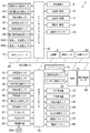
- FIG. 4 It is a block diagram of the air conditioning apparatus for vehicles explaining the air conditioning (priority) + battery cooling mode and battery cooling (priority) + air conditioning mode by the heat pump controller of the control apparatus of FIG. It is a block diagram of the vehicle air conditioning apparatus explaining the battery cooling (single) mode by the heat pump controller of the control apparatus of FIG. It is a block diagram of the air conditioning apparatus for vehicles explaining the defrost mode by the heat pump controller of the control apparatus of FIG. It is a control block diagram regarding compressor control of the heat pump controller of the control device of FIG. FIG. 4 is another control block diagram related to compressor control of the heat pump controller of the control device in FIG. 2.
- FIG. 7 is yet another control block diagram related to compressor control of the heat pump controller of the control device in FIG. 2. It is a block diagram explaining control of the solenoid valve 35 in battery cooling (priority) + air conditioning mode of the heat pump controller of the control apparatus of FIG. It is a figure explaining the control information input into the heat pump controller of the control apparatus of FIG. 2, and execution propriety of each operation mode.
- FIG. 1 shows a configuration diagram of a vehicle air conditioner 1 of an embodiment of the present invention.
- a vehicle of an embodiment to which the present invention is applied is an electric vehicle (EV) in which an engine (internal combustion engine) is not mounted, and electric power charged in a battery 55 mounted in the vehicle is used as a traveling motor (electric motor). (Not shown) to drive and run, and the compressor 2 of the vehicle air conditioner 1 of the present invention, which will be described later, is also driven by the electric power supplied from the battery 55. ..
- EV electric vehicle
- an engine internal combustion engine
- electric motor traveling motor
- the vehicle air conditioner 1 of the embodiment is a heating mode, a dehumidification heating mode, a dehumidification cooling mode, a cooling mode, and a defrosting mode in a heat pump operation using the refrigerant circuit R in an electric vehicle that cannot be heated by engine waste heat.
- the air conditioning (priority) + battery cooling mode, the battery cooling (priority) + air conditioning mode, and the battery cooling (single) mode are switched and executed to perform air conditioning in the vehicle compartment and temperature control of the battery 55. It is a thing.
- the present invention is effective not only for electric vehicles but also for so-called hybrid vehicles that use an engine and a running motor.
- the vehicle to which the vehicle air conditioner 1 of the embodiment is applied is one in which the battery 55 can be charged from an external charger (a quick charger or a normal charger).
- the battery 55, the traveling motor, the inverter controlling the same, and the like described above are the objects of temperature adjustment mounted on the vehicle in the present invention, but in the following embodiments, the battery 55 will be taken as an example for description.
- the vehicle air conditioner 1 of the embodiment is for performing air conditioning (heating, cooling, dehumidification, and ventilation) of a vehicle interior of an electric vehicle, and an electric compressor 2 for compressing a refrigerant and an interior of the vehicle interior.
- an outdoor expansion valve 6 consisting of a motor-operated valve (electronic expansion valve) for decompressing and expanding the refrigerant during heating, and as a radiator for radiating the refrigerant during cooling
- An outdoor heat exchanger 7 that functions and performs heat exchange between the refrigerant and the outside air so as to function as an evaporator that absorbs the refrigerant (absorbs heat into the refrigerant) during heating, and a mechanical expansion valve that decompresses and expands the refrigerant.
- an indoor expansion valve 8 made up of a heat exchanger as an indoor heat exchanger that is provided in the air flow passage 3 to evaporate the refrigerant during cooling and dehumidification to absorb the heat from the inside and outside of the vehicle (the refrigerant absorbs heat).
- the accumulator 12 and the like are sequentially connected by a refrigerant pipe 13 to form a refrigerant circuit R.
- the outdoor expansion valve 6 decompresses and expands the refrigerant flowing out of the radiator 4 and flowing into the outdoor heat exchanger 7, and can be fully closed. Further, in the embodiment, the indoor expansion valve 8 using the mechanical expansion valve decompresses and expands the refrigerant flowing into the heat absorber 9, and adjusts the degree of superheat of the refrigerant in the heat absorber 9.
- the outdoor heat exchanger 7 is provided with an outdoor blower 15.
- the outdoor blower 15 exchanges heat between the outdoor air and the refrigerant by forcibly ventilating the outdoor air through the outdoor heat exchanger 7, whereby the outdoor air is discharged while the vehicle is stopped (that is, the vehicle speed is 0 km / h).
- the heat exchanger 7 is configured to ventilate outside air.
- the outdoor heat exchanger 7 has a receiver dryer section 14 and a supercooling section 16 sequentially on the downstream side of the refrigerant, and the refrigerant pipe 13A on the refrigerant outlet side of the outdoor heat exchanger 7 is used when flowing the refrigerant to the heat absorber 9.
- the refrigerant pipe 13B on the outlet side of the subcooling unit 16 is connected to the receiver dryer unit 14 via an electromagnetic valve 17 (for cooling) as an open / close valve, and the check valve 18, the indoor expansion valve 8, and the indoor It is connected to the refrigerant inlet side of the heat absorber 9 through a solenoid valve 35 (for cabin) as a heat exchanger valve device (open / close valve) in order.
- the receiver dryer unit 14 and the supercooling unit 16 structurally form a part of the outdoor heat exchanger 7.
- the check valve 18 has the forward direction of the indoor expansion valve 8.
- the refrigerant pipe 13A that has exited from the outdoor heat exchanger 7 is branched into a refrigerant pipe 13D, and this branched refrigerant pipe 13D is passed through a solenoid valve 21 (for heating) that is opened and closed during heating. It is connected to the refrigerant pipe 13C on the refrigerant outlet side of the heat absorber 9 for communication.
- the refrigerant pipe 13C is connected to the inlet side of the accumulator 12, and the outlet side of the accumulator 12 is connected to the refrigerant suction side refrigerant pipe 13K of the compressor 2.
- a strainer 19 is connected to the refrigerant pipe 13E on the refrigerant outlet side of the radiator 4, and the refrigerant pipe 13E is connected to the refrigerant pipes 13J and 13F before the outdoor expansion valve 6 (refrigerant upstream side).
- One of the branched and branched refrigerant pipes 13J is connected to the refrigerant inlet side of the outdoor heat exchanger 7 via the outdoor expansion valve 6.
- the other branched refrigerant pipe 13F is connected to the refrigerant downstream side of the check valve 18 and the refrigerant upstream side of the indoor expansion valve 8 via an electromagnetic valve 22 (for dehumidification) as an opening / closing valve that is opened during dehumidification. It is communicatively connected to the located refrigerant pipe 13B.
- the refrigerant pipe 13F is connected in parallel to the series circuit of the outdoor expansion valve 6, the outdoor heat exchanger 7 and the check valve 18, and the outdoor expansion valve 6, the outdoor heat exchanger 7 and the check valve are connected. It becomes a bypass circuit that bypasses 18. Further, a solenoid valve 20 as an opening / closing valve for bypass is connected in parallel to the outdoor expansion valve 6.
- an intake switching damper 26 is provided at 25 for switching the air introduced into the air flow passage 3 between the inside air (inside air circulation) which is the air inside the vehicle interior and the outside air (outside air introduction) which is the air outside the vehicle interior.
- an indoor blower (blower fan) 27 for feeding the introduced inside air or outside air to the air flow passage 3 is provided.
- the intake switching damper 26 of the embodiment opens and closes the outside air intake port and the inside air intake port of the intake port 25 at an arbitrary ratio to remove the air (outside air and inside air) flowing into the heat absorber 9 of the air flow passage 3. It is configured so that the ratio of inside air can be adjusted between 0% and 100% (the ratio of outside air can also be adjusted between 100% and 0%).
- an auxiliary heater 23 as an auxiliary heating device including a PTC heater (electric heater) is provided in the embodiment, and passes through the radiator 4. It is possible to heat the air supplied to the passenger compartment. Further, in the air flow passage 3 on the air upstream side of the radiator 4, the air (inside air or outside air) flowing into the air flow passage 3 and passing through the heat absorber 9 is radiated. An air mix damper 28 that adjusts the ratio of ventilation to the device 4 and the auxiliary heater 23 is provided.
- the vehicle air conditioner 1 includes an equipment temperature adjusting device 61 for adjusting the temperature of the battery 55 by circulating a heat medium in the battery 55 (object to be temperature adjusted).
- the device temperature adjusting apparatus 61 of the embodiment circulates the heat medium between the refrigerant-heat medium heat exchanger 64 and the battery 55, which is a heat exchanger for the temperature-controlled object.
- a circulation pump 62 as a circulation device for this purpose and a heat medium heater 63 as a heating device are provided, and these and the battery 55 are annularly connected by a heat medium pipe 66.
- the inlet of the heat medium passage 64A of the refrigerant-heat medium heat exchanger 64 is connected to the discharge side of the circulation pump 62, and the outlet of this heat medium passage 64A is connected to the inlet of the heat medium heater 63.
- the outlet of the heat medium heater 63 is connected to the inlet of the battery 55, and the outlet of the battery 55 is connected to the suction side of the circulation pump 62.
- the heat medium used in the device temperature adjusting device 61 for example, water, a refrigerant such as HFO-1234yf, a liquid such as coolant, or a gas such as air can be adopted.
- water is used as the heat medium.
- the heat medium heater 63 is composed of an electric heater such as a PTC heater. Further, it is assumed that, for example, a jacket structure is provided around the battery 55 so that a heat medium can flow in a heat exchange relationship with the battery 55.
- the heat medium discharged from the circulation pump 62 flows into the heat medium flow passage 64A of the refrigerant-heat medium heat exchanger 64.
- the heat medium exiting the heat medium flow passage 64A of the refrigerant-heat medium heat exchanger 64 reaches the heat medium heating heater 63, and if the heat medium heating heater 63 is generating heat, the heat medium heating heater 63 heats the heat medium heating heater 63 and then the battery. 55, where the heat medium exchanges heat with the battery 55.
- the heat medium that has exchanged heat with the battery 55 is sucked into the circulation pump 62 and circulated in the heat medium pipe 66.
- a branch pipe 67 as a branch circuit is provided in the refrigerant pipe 13B located on the refrigerant downstream side of the connecting portion between the refrigerant pipe 13F and the refrigerant pipe 13B of the refrigerant circuit R and on the refrigerant upstream side of the indoor expansion valve 8.
- auxiliary expansion valve 68 which is a mechanical expansion valve in the embodiment, and a solenoid valve (for chiller) 69 as a valve device (open / close valve) for temperature control are sequentially provided in the branch pipe 67.
- the auxiliary expansion valve 68 decompresses and expands the refrigerant flowing into a later-described refrigerant passage 64B of the refrigerant-heat medium heat exchanger 64, and adjusts the degree of superheat of the refrigerant in the refrigerant passage 64B of the refrigerant-heat medium heat exchanger 64. To do.
- the other end of the branch pipe 67 is connected to the refrigerant flow passage 64B of the refrigerant-heat medium heat exchanger 64, and one end of the refrigerant pipe 71 is connected to the outlet of the refrigerant flow passage 64B.
- the other end is connected to a refrigerant pipe 13C on the refrigerant upstream side (refrigerant upstream side of the accumulator 12) from the confluence with the refrigerant pipe 13D.
- the auxiliary expansion valve 68, the electromagnetic valve 69, the refrigerant flow path 64B of the refrigerant-heat medium heat exchanger 64, and the like also form a part of the refrigerant circuit R and, at the same time, a part of the device temperature adjusting device 61. It will be.
- the solenoid valve 69 When the solenoid valve 69 is open, the refrigerant (a part or all of the refrigerant) discharged from the outdoor heat exchanger 7 flows into the branch pipe 67, the pressure is reduced by the auxiliary expansion valve 68, and then the refrigerant is passed through the solenoid valve 69. -The refrigerant flows into the refrigerant channel 64B of the heat medium heat exchanger 64 and evaporates there. The refrigerant absorbs heat from the heat medium flowing through the heat medium passage 64A while flowing through the refrigerant passage 64B, and then is sucked into the compressor 2 through the refrigerant pipe 13K through the branch pipe 71, the refrigerant pipe 13C, and the accumulator 12.
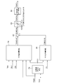
- FIG. 2 shows a block diagram of the control device 11 of the vehicle air conditioner 1 of the embodiment.
- the control device 11 includes an air conditioning controller 45 and a heat pump controller 32, each of which is composed of a microcomputer, which is an example of a computer including a processor, and these are a CAN (Controller Area Network) and a LIN (Local Interconnect Network). Is connected to the vehicle communication bus 65 that constitutes the. Further, the compressor 2 and the auxiliary heater 23, the circulation pump 62 and the heat medium heating heater 63 are also connected to the vehicle communication bus 65, and the air conditioning controller 45, the heat pump controller 32, the compressor 2, the auxiliary heater 23, the circulation pump 62 and the heat generator.
- the medium heater 64 is configured to send and receive data via the vehicle communication bus 65.
- the vehicle communication bus 65 includes a vehicle controller 72 (ECU) that controls the entire vehicle including traveling, a battery controller (BMS: Battery Management System) 73 that controls the charging and discharging of the battery 55, and a GPS navigation device 74.
- the vehicle controller 72, the battery controller 73, and the GPS navigation device 74 are also configured by a microcomputer that is an example of a computer including a processor.
- the air conditioning controller 45 and the heat pump controller 32 that configure the control device 11 connect the vehicle communication bus 65 to each other. Information (data) is transmitted and received to and from the vehicle controller 72, the battery controller 73, and the GPS navigation device 74 via the above.
- the air conditioning controller 45 is a higher-level controller that controls the vehicle interior air conditioning.
- the inputs of the air conditioning controller 45 are an outside air temperature sensor 33 that detects the outside air temperature Tam of the vehicle and an outside air humidity that detects outside air humidity.
- the sensor 34, the HVAC suction temperature sensor 36 that detects the temperature of the air that is sucked into the air flow passage 3 from the suction port 25 and flows into the heat absorber 9, and the inside air temperature sensor 37 that detects the temperature of the air (inside air) in the vehicle compartment.
- An inside air humidity sensor 38 for detecting the humidity of the air in the vehicle compartment
- an indoor CO 2 concentration sensor 39 for detecting the carbon dioxide concentration in the vehicle compartment
- an outlet temperature sensor 41 for detecting the temperature of the air blown into the vehicle compartment.
- An air conditioning operation unit 53 for performing air conditioning setting operations in the vehicle interior such as mode switching and information display is connected.
- 53A is a display as a display output device provided in the air conditioning operation unit 53.
- the output of the air conditioning controller 45 includes an outdoor blower 15, an indoor blower (blower fan) 27, a suction switching damper 26, an air mix damper 28, an outlet switching damper 31, a solenoid valve 35 (for a cabin) and An electromagnetic valve 69 (for chiller) is connected and controlled by the air conditioning controller 45.
- the heat pump controller 32 is a controller that mainly controls the refrigerant circuit R, and the heat pump controller 32 has an input that releases heat to detect the refrigerant inlet temperature Tcxin of the radiator 4 (which is also the refrigerant temperature discharged from the compressor 2).
- Radiator pressure sensor 47 for detecting the refrigerant pressure (pressure of radiator 4; radiator pressure Pci), and temperature of heat absorber 9 (temperature of heat absorber 9 itself, or air immediately after being cooled by heat absorber 9) Temperature of (cooling target): Heat absorber temperature sensor 48 for detecting heat absorber temperature Te, and refrigerant temperature at the outlet of the outdoor heat exchanger 7 (refrigerant evaporation temperature of the outdoor heat exchanger 7: outdoor heat exchanger temperature) Outputs of the outdoor heat exchanger temperature sensor 49 for detecting TXO) and the auxiliary heater temperature sensors 50A (driver side) and 50B (passenger side) for detecting the temperature of the auxiliary heater 23 are connected.
- the output of the heat pump controller 32 includes the outdoor expansion valve 6, the solenoid valve 22 (for dehumidification), the solenoid valve 17 (for cooling), the solenoid valve 21 (for heating), and the solenoid valve 20 (for bypass). Are connected and they are controlled by the heat pump controller 32.
- Each of the compressor 2, the auxiliary heater 23, the circulation pump 62 and the heat medium heating heater 63 has a built-in controller.
- the controllers of the compressor 2 and the auxiliary heater 23 are connected to the heat pump controller 32 via the vehicle communication bus 65. Data is transmitted / received and controlled by the heat pump controller 32.
- controllers of the circulation pump 62 and the heat medium heating heater 63 transmit and receive data to and from the air conditioning controller 45, and further exchange the data between the air conditioning controller 45 and the heat pump controller 32.
- the heat medium heater 63 is also controlled by the heat pump controller 32.
- the circulation pump 62 and the heat medium heater 63 that constitute the device temperature adjusting device 61 may be controlled by the battery controller 73. Further, in the battery controller 73, the temperature of the heat medium on the outlet side of the heat medium flow path 64A of the refrigerant-heat medium heat exchanger 64 of the device temperature adjusting device 61 (heat medium temperature Tw: heat exchanger for temperature controlled).
- the output of the heat medium temperature sensor 76 that detects the temperature of the object to be cooled by the battery is connected to the output of the battery temperature sensor 77 that detects the temperature of the battery 55 (the temperature of the battery 55 itself: the battery temperature Tcell).
- the remaining amount of the battery 55 (the amount of stored electricity), the information regarding the charging of the battery 55 (the information that the battery is being charged, the charging completion time, the remaining charging time, etc.), the heat medium temperature Tw, and the battery temperature Tcell are It is transmitted from the battery controller 73 to the air conditioning controller 45 and the vehicle controller 72 via the vehicle communication bus 65.
- the information regarding the charging completion time and the remaining charging time at the time of charging the battery 55 is information supplied from an external charger such as a quick charger described later.
- the heat pump controller 32 and the air conditioning controller 45 send and receive data to and from each other via the vehicle communication bus 65, and control each device based on the output of each sensor and the setting input by the air conditioning operation unit 53.
- Air volume Ga of air flowing into the air flow passage 3 and flowing in the air flow passage 3 (calculated by the air conditioning controller 45), air flow rate SW by the air mix damper 28 (calculated by the air conditioning controller 45), voltage of the indoor blower 27 (BLV), the information from the battery controller 73, the information from the GPS navigation device 74, and the output of the air conditioning operation unit 53 are transmitted from the air conditioning controller 45 to the heat pump controller 32 via the vehicle communication bus 65, and the heat pump controller 32 controls the heat pump controller 32. It is configured to be used for control.
- the heat pump controller 32 also transmits data (information) regarding the control of the refrigerant circuit R to the air conditioning controller 45 via the vehicle communication bus 65.
- a battery cooling request / battery heating request (including disconnection / short circuit abnormality) as a temperature control request for a temperature controlled object described later, a solenoid valve (for cabin) 35, and a solenoid valve (for chiller).
- operation information including disconnection / short circuit abnormality
- information on the heat medium temperature Tw and battery temperature Tcell from the battery controller 73 (disconnection / short circuit abnormality, heat medium temperature sensor 76 and battery temperature sensor 77 attachment) (Including abnormality) and operation information of circulation pump 62 and heat medium heater 63 (including abnormality of disconnection / short circuit) are transmitted to heat pump controller 32. Then, these are information necessary for temperature control of the battery (object to be temperature controlled) input to the heat pump controller 32, and hereinafter, these are referred to as battery temperature control information.
- HP control information the operation information of the devices other than the compressor 2, the blowers 15, 27, the dampers 26, 28, 31, the auxiliary heater 23, and the sensor information other than the above, such as temperature, humidity, pressure, and carbon dioxide concentration, , which is information necessary for air conditioning in the vehicle compartment, which is input to the heat pump controller 32, and is hereinafter referred to as HP control information.
- the control device 11 controls the heating mode, the dehumidifying heating mode, the dehumidifying cooling mode, the cooling mode, and the air conditioning operation of the air conditioning (priority) + battery cooling mode, and the battery cooling.
- Each battery cooling operation of (priority) + air conditioning mode and battery cooling (single) mode and defrosting mode are switched and executed. These are shown in FIG.
- the battery 55 is not charged in the embodiment, and the ignition of the vehicle is performed. This is executed when (IGN) is turned on and the air conditioning switch of the air conditioning operation unit 53 is turned on. However, it is executed even when the ignition is OFF during remote operation (pre-air conditioning, etc.). Even when the battery 55 is being charged, there is no battery cooling request, and the process is executed when the air conditioning switch is ON.
- each battery cooling operation in the battery cooling (priority) + air conditioning mode and the battery cooling (single) mode is executed, for example, when the plug of the quick charger (external power source) is connected and the battery 55 is being charged. It is something.
- the battery cooling (single) mode is executed when the air conditioning switch is OFF and there is a battery cooling request (during traveling at a high outside air temperature, etc.) other than during charging of the battery 55.
- the heat pump controller 32 operates the circulation pump 62 of the device temperature adjusting device 61 when the ignition is turned on, or when the battery 55 is being charged even when the ignition is turned off. It is assumed that the heat medium is circulated in the heat medium pipe 66 as indicated by broken lines in FIGS. Further, although not shown in FIG. 3, the heat pump controller 32 of the embodiment also has a battery heating mode (also an operation mode) in which the heat medium heating heater 63 of the device temperature adjusting device 61 is heated to heat the battery 55. Run.
- the air conditioning (priority) + battery cooling mode, the battery cooling (priority) + air conditioning mode, the battery cooling (single) mode, and the battery heating mode control the temperature of the battery 55 (object to be temperature controlled) in the present invention.
- the first operation mode is set, and the heating mode, the dehumidification heating mode, the dehumidification cooling mode, the cooling mode, and the defrosting mode are the second operation modes in the present invention in which the temperature of the battery 55 is not adjusted.
- the air conditioning (priority) + battery cooling mode and the battery cooling (priority) + air conditioning mode are the air conditioning + cooling subject cooling mode in the present invention
- the battery cooling (single) mode is the heating in the present invention.
- the target cooling (independent) mode is set.
- the air conditioning (priority) + battery cooling mode is the air conditioning (priority) + the temperature controlled cooling mode in the present invention
- the battery cooling (priority) + air conditioning mode is the temperature controlled cooling (priority) + the air conditioning in the present invention.
- the battery heating mode is the temperature controlled target heating mode in the present invention.
- the dehumidifying heating mode and the dehumidifying cooling mode are the dehumidifying modes in the present invention.
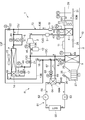
- FIG. 4 shows how the refrigerant flows in the refrigerant circuit R in the heating mode (solid arrow).
- the heat pump controller 32 opens the solenoid valve 21 and the solenoid valve 17 , The solenoid valve 20, the solenoid valve 22, the solenoid valve 35, and the solenoid valve 69 are closed. Then, the compressor 2 and the blowers 15 and 27 are operated, and the air mix damper 28 adjusts the ratio of the air blown from the indoor blower 27 to the radiator 4 and the auxiliary heater 23.
- the high-temperature and high-pressure gas refrigerant discharged from the compressor 2 flows into the radiator 4. Since the air in the air flow passage 3 is ventilated through the radiator 4, the air in the air flow passage 3 is heated by exchanging heat with the high temperature refrigerant in the radiator 4. On the other hand, the refrigerant in the radiator 4 is cooled by being deprived of heat by the air and condensed and liquefied.
- the liquefied refrigerant in the radiator 4 exits the radiator 4 and then reaches the outdoor expansion valve 6 via the refrigerant pipes 13E and 13J.
- the refrigerant flowing into the outdoor expansion valve 6 is decompressed there, and then flows into the outdoor heat exchanger 7.
- the refrigerant that has flowed into the outdoor heat exchanger 7 evaporates and pumps up heat from the outside air ventilated by traveling or by the outdoor blower 15 (heat absorption). That is, the refrigerant circuit R serves as a heat pump.
- the low-temperature refrigerant that has exited the outdoor heat exchanger 7 reaches the refrigerant pipe 13C via the refrigerant pipes 13A and 13D, the solenoid valve 21, and further enters the accumulator 12 via this refrigerant pipe 13C, where it is gas-liquid separated.
- the circulation in which the gas refrigerant is sucked into the compressor 2 from the refrigerant pipe 13K is repeated.
- the air heated by the radiator 4 is blown out from the air outlet 29, so that the interior of the vehicle is heated.
- the heat pump controller 32 calculates a target heater temperature TCO (of the radiator 4) calculated from a target outlet temperature TAO, which will be described later, which is a target temperature of the air blown into the vehicle interior (a target value of the temperature of the air blown into the vehicle interior).
- the target radiator pressure PCO is calculated from the target temperature), and the rotational speed of the compressor 2 is based on the target radiator pressure PCO and the radiator pressure Pci (high pressure of the refrigerant circuit R) detected by the radiator pressure sensor 47.
- the heat pump controller 32 supplements this shortage with the heat generated by the auxiliary heater 23. As a result, the vehicle interior is heated without any trouble even when the outside temperature is low.
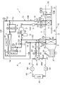
- FIG. 5 shows how the refrigerant flows in the refrigerant circuit R in the dehumidifying and heating mode (solid arrow).
- the heat pump controller 32 opens the solenoid valve 21, the solenoid valve 22, and the solenoid valve 35, and closes the solenoid valve 17, the solenoid valve 20, and the solenoid valve 69.
- the compressor 2 and the blowers 15 and 27 are operated, and the air mix damper 28 adjusts the ratio of the air blown from the indoor blower 27 to the radiator 4 and the auxiliary heater 23.
- the high-temperature and high-pressure gas refrigerant discharged from the compressor 2 flows into the radiator 4. Since the air in the air flow passage 3 is ventilated through the radiator 4, the air in the air flow passage 3 is heated by exchanging heat with the high temperature refrigerant in the radiator 4. On the other hand, the refrigerant in the radiator 4 is cooled by being deprived of heat by the air and condensed and liquefied.
- the refrigerant liquefied in the radiator 4 exits the radiator 4, a part of it enters the refrigerant pipe 13J through the refrigerant pipe 13E and reaches the outdoor expansion valve 6.
- the refrigerant flowing into the outdoor expansion valve 6 is decompressed there, and then flows into the outdoor heat exchanger 7.
- the refrigerant that has flowed into the outdoor heat exchanger 7 evaporates and pumps up heat from the outside air ventilated by traveling or by the outdoor blower 15 (heat absorption).
- the low-temperature refrigerant leaving the outdoor heat exchanger 7 reaches the refrigerant pipe 13C via the refrigerant pipes 13A and 13D and the solenoid valve 21, enters the accumulator 12 via the refrigerant pipe 13C, and is separated into gas and liquid there. After that, the circulation in which the gas refrigerant is sucked into the compressor 2 from the refrigerant pipe 13K is repeated.
- the rest of the condensed refrigerant flowing through the radiator pipe 13E via the radiator 4 is diverted, and the diverted refrigerant flows into the refrigerant pipe 13F via the solenoid valve 22 and reaches the refrigerant pipe 13B.
- the refrigerant reaches the indoor expansion valve 8, is decompressed by the indoor expansion valve 8, then flows into the heat absorber 9 via the electromagnetic valve 35, and is evaporated.
- the water in the air blown out from the indoor blower 27 is condensed and adheres to the heat absorber 9 due to the heat absorbing action of the refrigerant generated in the heat absorber 9, so that the air is cooled and dehumidified.
- the refrigerant evaporated in the heat absorber 9 flows out into the refrigerant pipe 13C, joins the refrigerant from the refrigerant pipe 13D (refrigerant from the outdoor heat exchanger 7), and then is sucked into the compressor 2 from the refrigerant pipe 13K via the accumulator 12. Repeat the cycle.
- the air dehumidified by the heat absorber 9 is reheated in the process of passing through the radiator 4 and the auxiliary heater 23 (when heat is generated), so that dehumidification and heating of the vehicle interior is performed.
- the heat pump controller 32 rotates the compressor 2 based on the target radiator pressure PCO calculated from the target heater temperature TCO and the radiator pressure Pci (high pressure of the refrigerant circuit R) detected by the radiator pressure sensor 47. Or the rotation speed of the compressor 2 based on the temperature of the heat absorber 9 (heat absorber temperature Te) detected by the heat absorber temperature sensor 48 and the target heat absorber temperature TEO which is its target value. .
- the heat pump controller 32 controls the compressor 2 by selecting whichever of the radiator target pressure Pci and the heat absorber temperature Te, whichever is lower than the target compressor speed obtained from the calculation. Further, the valve opening degree of the outdoor expansion valve 6 is controlled based on the heat absorber temperature Te.
- the heat pump controller 32 supplements the shortage with the heat generated by the auxiliary heater 23. .. As a result, the vehicle interior is dehumidified and heated even when the outside temperature is low.
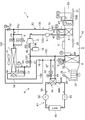
- FIG. 6 shows how the refrigerant flows in the refrigerant circuit R in the dehumidifying and cooling mode (solid arrow).
- the heat pump controller 32 opens the solenoid valve 17 and the solenoid valve 35, and closes the solenoid valve 20, the solenoid valve 21, the solenoid valve 22, and the solenoid valve 69.
- the compressor 2 and the blowers 15 and 27 are operated, and the air mix damper 28 adjusts the ratio of the air blown from the indoor blower 27 to the radiator 4 and the auxiliary heater 23.
- the high-temperature and high-pressure gas refrigerant discharged from the compressor 2 flows into the radiator 4. Since the air in the air flow passage 3 is ventilated through the radiator 4, the air in the air flow passage 3 is heated by exchanging heat with the high temperature refrigerant in the radiator 4. On the other hand, the refrigerant in the radiator 4 is cooled by being deprived of heat by the air, and is condensed and liquefied.
- the refrigerant exiting the radiator 4 reaches the outdoor expansion valve 6 via the refrigerant pipes 13E and 13J, and then passes through the outdoor expansion valve 6 controlled to open more (a larger valve opening area) than the heating mode or the dehumidifying and heating mode. It flows into the outdoor heat exchanger 7.
- the refrigerant that has flowed into the outdoor heat exchanger 7 is condensed by being cooled there by traveling or by the outside air ventilated by the outdoor blower 15.
- the refrigerant discharged from the outdoor heat exchanger 7 enters the refrigerant pipe 13B via the refrigerant pipe 13A, the solenoid valve 17, the receiver dryer unit 14, and the supercooling unit 16, and reaches the indoor expansion valve 8 via the check valve 18.
- the refrigerant is decompressed by the indoor expansion valve 8, then flows into the heat absorber 9 through the electromagnetic valve 35, and evaporates. Due to the heat absorbing action at this time, moisture in the air blown out from the indoor blower 27 is condensed and attached to the heat absorber 9, and the air is cooled and dehumidified.
- the refrigerant evaporated in the heat absorber 9 reaches the accumulator 12 via the refrigerant pipe 13C, and is repeatedly sucked into the compressor 2 from the refrigerant pipe 13K via the refrigerant pipe 13K.
- the air cooled and dehumidified by the heat absorber 9 is reheated (has a lower heating capacity than that during dehumidification heating) in the process of passing through the radiator 4 and the auxiliary heater 23 (when heat is generated). As a result, dehumidification and cooling of the vehicle interior are performed.
- the heat pump controller 32 absorbs heat based on the temperature of the heat absorber 9 (heat absorber temperature Te) detected by the heat absorber temperature sensor 48 and the target heat absorber temperature TEO which is the target temperature of the heat absorber 9 (target value of the heat absorber temperature Te).
- the rotation speed of the compressor 2 is controlled so that the device temperature Te becomes the target heat absorber temperature TEO, and the radiator pressure Pci (high pressure of the refrigerant circuit R) detected by the radiator pressure sensor 47 and the target radiator pressure PCO.
- the valve opening of the outdoor expansion valve 6 is controlled so that the radiator pressure Pci becomes the target radiator pressure PCO. Amount).
- the heat pump controller 32 supplements the shortage with the heat generated by the auxiliary heater 23. To do. As a result, dehumidifying and cooling are performed without lowering the temperature inside the vehicle compartment too much.
- FIG. 7 shows how the refrigerant flows in the refrigerant circuit R in the cooling mode (solid arrow).
- the heat pump controller 32 opens the solenoid valve 17, the solenoid valve 20, and the solenoid valve 35, and closes the solenoid valve 21, the solenoid valve 22, and the solenoid valve 69.
- the compressor 2 and the blowers 15 and 27 are operated, and the air mix damper 28 adjusts the ratio of the air blown from the indoor blower 27 to the radiator 4 and the auxiliary heater 23.
- the auxiliary heater 23 is not energized.
- the high-temperature and high-pressure gas refrigerant discharged from the compressor 2 flows into the radiator 4.
- the air in the air flow passage 3 is ventilated through the radiator 4, since the proportion thereof is small (because of only reheating (reheating) during cooling), it almost passes through the radiator 4,
- the discharged refrigerant reaches the refrigerant pipe 13J via the refrigerant pipe 13E.
- the electromagnetic valve 20 is opened, the refrigerant passes through the electromagnetic valve 20 and flows into the outdoor heat exchanger 7 as it is, and is cooled there by traveling or by the outside air ventilated by the outdoor blower 15 to be condensed and liquefied. To do.
- the refrigerant discharged from the outdoor heat exchanger 7 enters the refrigerant pipe 13B via the refrigerant pipe 13A, the solenoid valve 17, the receiver dryer unit 14, and the supercooling unit 16, and reaches the indoor expansion valve 8 via the check valve 18.
- the refrigerant is decompressed by the indoor expansion valve 8, then flows into the heat absorber 9 through the electromagnetic valve 35, and evaporates. Due to the heat absorbing action at this time, the air blown out from the indoor blower 27 and exchanging heat with the heat absorber 9 is cooled.
- the refrigerant evaporated in the heat absorber 9 reaches the accumulator 12 via the refrigerant pipe 13C, and then is sucked into the compressor 2 via the refrigerant pipe 13K.
- the air cooled by the heat absorber 9 is blown into the vehicle interior from the air outlet 29, so that the vehicle interior is cooled.
- the heat pump controller 32 controls the rotation speed of the compressor 2 based on the temperature of the heat absorber 9 (heat absorber temperature Te) detected by the heat absorber temperature sensor 48.
- Air conditioning (priority) + battery cooling mode first operation mode, air conditioning + temperature controlled cooling mode, air conditioning (priority) + temperature controlled cooling mode
- the air conditioning (priority) + battery cooling mode will be described with reference to FIG.
- FIG. 8 shows how the refrigerant flows in the refrigerant circuit R (solid arrow) in the air conditioning (priority) + battery cooling mode.
- the heat pump controller 32 opens the electromagnetic valve 17, the electromagnetic valve 20, the electromagnetic valve 35, and the electromagnetic valve 69, and closes the electromagnetic valves 21 and 22.
- the compressor 2 and the blowers 15 and 27 are operated, and the air mix damper 28 adjusts the ratio of the air blown from the indoor blower 27 to the radiator 4 and the auxiliary heater 23.
- the auxiliary heater 23 is not energized.
- the heat medium heater 63 is not energized.
- the high-temperature and high-pressure gas refrigerant discharged from the compressor 2 flows into the radiator 4.
- the air in the air flow passage 3 is ventilated through the radiator 4, since the proportion thereof is small (because of only reheating (reheating) during cooling), it almost passes through the radiator 4,
- the discharged refrigerant reaches the refrigerant pipe 13J via the refrigerant pipe 13E.
- the electromagnetic valve 20 is opened, the refrigerant passes through the electromagnetic valve 20 and flows into the outdoor heat exchanger 7 as it is, and is cooled there by traveling or by the outside air ventilated by the outdoor blower 15 to be condensed and liquefied. To do.
- the refrigerant exiting the outdoor heat exchanger 7 enters the refrigerant pipe 13B through the refrigerant pipe 13A, the solenoid valve 17, the receiver dryer unit 14, and the supercooling unit 16.
- the refrigerant flowing into the refrigerant pipe 13B is branched after passing through the check valve 18, and one of the refrigerant flows through the refrigerant pipe 13B as it is to reach the indoor expansion valve 8.
- the refrigerant flowing into the indoor expansion valve 8 is decompressed there, then flows into the heat absorber 9 through the electromagnetic valve 35, and is evaporated. Due to the heat absorbing action at this time, the air blown out from the indoor blower 27 and exchanging heat with the heat absorber 9 is cooled.
- the refrigerant evaporated in the heat absorber 9 reaches the accumulator 12 via the refrigerant pipe 13C, and then is sucked into the compressor 2 via the refrigerant pipe 13K.
- the air cooled by the heat absorber 9 is blown into the vehicle interior from the air outlet 29, so that the vehicle interior is cooled.
- the rest of the refrigerant that has passed through the check valve 18 is split, flows into the branch pipe 67, and reaches the auxiliary expansion valve 68.
- the refrigerant is decompressed, then flows into the refrigerant channel 64B of the refrigerant-heat medium heat exchanger 64 via the electromagnetic valve 69, and evaporates there. At this time, it exerts an endothermic effect.
- the refrigerant evaporated in the refrigerant passage 64B repeats the circulation in which the refrigerant is sucked into the compressor 2 from the refrigerant pipe 13K through the refrigerant pipe 71, the refrigerant pipe 13C and the accumulator 12 in sequence (shown by a solid arrow in FIG. 8).
- the heat medium discharged from the circulation pump 62 reaches the heat medium flow passage 64A of the refrigerant-heat medium heat exchanger 64 in the heat medium pipe 66, and the refrigerant flow passage there.
- the heat medium is cooled by exchanging heat with the refrigerant that evaporates in 64B and absorbing heat.
- the heat medium exiting the heat medium flow path 64A of the refrigerant-heat medium heat exchanger 64 reaches the heat medium heater 63.
- the heat medium heating heater 63 does not generate heat in this operation mode, the heat medium passes through as it is to the battery 55 and exchanges heat with the battery 55. As a result, the battery 55 is cooled, and the heat medium after cooling the battery 55 is repeatedly sucked into the circulation pump 62 and repeatedly circulated (indicated by a dashed arrow in FIG. 8).
- the heat pump controller 32 maintains the electromagnetic valve 35 in the open state, and will be described later based on the temperature of the heat absorber 9 (heat absorber temperature Te) detected by the heat absorber temperature sensor 48.
- the rotation speed of the compressor 2 is controlled as shown in FIG.
- the solenoid valve 69 is controlled to open and close as follows based on the temperature of the heat medium detected by the heat medium temperature sensor 76 (heat medium temperature Tw: transmitted from the battery controller 73).
- the heat absorber temperature Te is the temperature of the heat absorber 9 in the embodiment or the temperature of the object (air) cooled by it.
- the heat medium temperature Tw is adopted as the temperature of the object (heat medium) cooled by the refrigerant-heat medium heat exchanger 64 (heat exchanger for temperature adjustment) in the embodiment, but the temperature adjustment is performed. It is also an index showing the temperature of the target battery 55 (hereinafter the same).
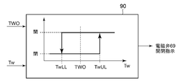
- FIG. 13 shows a block diagram of opening / closing control of the solenoid valve 69 in this air conditioning (priority) + battery cooling mode.
- the heat medium temperature Tw detected by the heat medium temperature sensor 76 and a predetermined target heat medium temperature TWO as a target value of the heat medium temperature Tw are input to the temperature controlled target electromagnetic valve control unit 90 of the heat pump controller 32. It Then, the temperature controlled target electromagnetic valve control unit 90 sets the upper limit value TwUL and the lower limit value TwLL with a predetermined temperature difference above and below the target heat medium temperature TWO, and from the state where the electromagnetic valve 69 is closed.
- the solenoid valve 69 is opened (instruction to open the solenoid valve 69).
- the refrigerant flows into the refrigerant channel 64B of the refrigerant-heat medium heat exchanger 64, evaporates, and cools the heat medium flowing through the heat medium channel 64A. Therefore, the battery 55 is cooled by the cooled heat medium. To be done.
- the solenoid valve 69 is closed (instruction to close the solenoid valve 69). After that, the solenoid valve 69 is repeatedly opened and closed as described above to control the heat medium temperature Tw to the target heat medium temperature TWO while giving priority to the cooling in the vehicle compartment, to cool the battery 55.
- the heat pump controller 32 calculates the above-mentioned target outlet temperature TAO from the following formula (I).
- the target outlet temperature TAO is a target value of the temperature of the air blown into the vehicle compartment from the outlet 29.
- TAO (Tset-Tin) ⁇ K + Tbal (f (Tset, SUN, Tam)) .. (I)
- Tset is the set temperature of the vehicle interior set by the air conditioning operation unit 53
- Tin is the temperature of the vehicle interior air detected by the inside air temperature sensor 37
- K is a coefficient
- Tbal is the set temperature Tset
- the solar radiation sensor 51 detects the temperature. It is a balance value calculated from the amount of solar radiation SUN and the outside air temperature Tam detected by the outside air temperature sensor 33.
- the target outlet temperature TAO is higher as the outside air temperature Tam is lower, and is decreased as the outside air temperature Tam is increased.
- the heat pump controller 32 selects any one of the above air conditioning operations based on the outside air temperature Tam detected by the outside air temperature sensor 33 and the target outlet temperature TAO at the time of startup. Further, after the start-up, each of the air conditioning operations is selected and switched according to changes in operating conditions such as the outside air temperature Tam, the target outlet temperature TAO, and the heat medium temperature Tw, environmental conditions, and setting conditions. For example, the transition from the cooling mode to the air conditioning (priority) + battery cooling mode is executed based on the input of the battery cooling request (temperature control target of the temperature controlled target) from the battery controller 73. In this case, the battery controller 73 outputs a battery cooling request and transmits it to the heat pump controller 32 and the air conditioning controller 45, for example, when the heat medium temperature Tw or the battery temperature Tcell rises above a predetermined value.
- Battery cooling (priority) + air conditioning mode first operation mode, air conditioning + temperature controlled cooling mode, temperature controlled cooling (priority) + air conditioning mode
- the operation during charging of the battery 55 will be described. For example, when a plug for charging a quick charger (external power source) is connected and the battery 55 is being charged (these information is transmitted from the battery controller 73), the ignition (IGN) of the vehicle is turned on / off. Regardless, the heat pump controller 32 executes the battery cooling (priority) + air conditioning mode when there is a battery cooling request (a temperature adjustment request for the temperature controlled object) and the air conditioning switch of the air conditioning operation unit 53 is turned on.
- the flow of the refrigerant in the refrigerant circuit R in the battery cooling (priority) + air conditioning mode is the same as in the air conditioning (priority) + battery cooling mode shown in FIG.
- the heat pump controller 32 maintains the electromagnetic valve 69 in an open state, and the heat detected by the heat medium temperature sensor 76 (transmitted from the battery controller 73) is detected.
- the medium temperature Tw Based on the medium temperature Tw, the rotation speed of the compressor 2 is controlled as shown in FIG. 14 described later.
- the solenoid valve 35 is controlled to open and close as follows based on the temperature of the heat absorber 9 (heat absorber temperature Te) detected by the heat absorber temperature sensor 48.
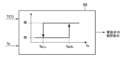
- FIG. 15 shows a block diagram of opening / closing control of the solenoid valve 35 in this battery cooling (priority) + air conditioning mode.
- the heat absorber electromagnetic valve control unit 95 of the heat pump controller 32 is input with the heat absorber temperature Te detected by the heat absorber temperature sensor 48 and a predetermined target heat absorber temperature TEO as a target value of the heat absorber temperature Te. Then, the heat absorber electromagnetic valve control unit 95 sets the upper limit value TeUL and the lower limit value TeLL with a predetermined temperature difference above and below the target heat absorber temperature TEO, and sets the heat absorber temperature from the state in which the solenoid valve 35 is closed.
- the solenoid valve 35 is closed (instruction to close the solenoid valve 35). Thereafter, such opening / closing of the solenoid valve 35 is repeated to control the heat absorber temperature Te to the target heat absorber temperature TEO while prioritizing the cooling of the battery 55 to cool the vehicle interior.
- Battery cooling (single) mode first operating mode, temperature controlled cooling (single) mode
- the heat pump controller 32 executes the battery cooling (single) mode.
- the air conditioning switch is OFF and there is a battery cooling request (during traveling at a high outside air temperature) other than during charging of the battery 55.
- FIG. 9 shows how the refrigerant flows in the refrigerant circuit R (solid arrow) in the battery cooling (single) mode.
- the heat pump controller 32 opens the solenoid valve 17, the solenoid valve 20, and the solenoid valve 69, and closes the solenoid valve 21, the solenoid valve 22, and the solenoid valve 35.
- the compressor 2 and the outdoor blower 15 are operated.
- the indoor blower 27 is not operated and the auxiliary heater 23 is not energized. Further, the heat medium heater 63 is not energized in this operation mode.
- the high-temperature and high-pressure gas refrigerant discharged from the compressor 2 flows into the radiator 4. Since the air in the air flow passage 3 is not ventilated to the radiator 4, it passes only here, and the refrigerant exiting the radiator 4 reaches the refrigerant pipe 13J via the refrigerant pipe 13E. At this time, since the electromagnetic valve 20 is open, the refrigerant passes through the electromagnetic valve 20 and flows into the outdoor heat exchanger 7 as it is, where it is air-cooled by the outside air ventilated by the outdoor blower 15 to be condensed and liquefied.
- the refrigerant exiting the outdoor heat exchanger 7 enters the refrigerant pipe 13B through the refrigerant pipe 13A, the solenoid valve 17, the receiver dryer unit 14, and the supercooling unit 16. After passing through the check valve 18, all of the refrigerant flowing into the refrigerant pipe 13B flows into the branch pipe 67 and reaches the auxiliary expansion valve 68. Here, the refrigerant is decompressed, then flows into the refrigerant channel 64B of the refrigerant-heat medium heat exchanger 64 via the electromagnetic valve 69, and evaporates there. At this time, it exerts an endothermic effect.
- the refrigerant evaporated in the refrigerant flow path 64B repeatedly passes through the refrigerant pipe 71, the refrigerant pipe 13C, and the accumulator 12 and is repeatedly sucked into the compressor 2 from the refrigerant pipe 13K (represented by a solid arrow in FIG. 9).
- the heat medium discharged from the circulation pump 62 reaches the heat medium flow passage 64A of the refrigerant-heat medium heat exchanger 64 in the heat medium pipe 66, and the refrigerant flow passage there.
- the heat medium is cooled by being absorbed by the refrigerant evaporated in 64B.
- the heat medium exiting the heat medium flow path 64A of the refrigerant-heat medium heat exchanger 64 reaches the heat medium heater 63.
- the heat medium heating heater 63 does not generate heat in this operation mode, the heat medium passes through as it is to the battery 55 and exchanges heat with the battery 55. As a result, the battery 55 is cooled, and the heat medium after cooling the battery 55 is repeatedly sucked into the circulation pump 62 and repeatedly circulated (indicated by a dashed arrow in FIG. 9).
- the heat pump controller 32 cools the battery 55 by controlling the number of revolutions of the compressor 2 based on the heat medium temperature Tw detected by the heat medium temperature sensor 76 as described later.
- FIG. 10 shows how the refrigerant flows in the refrigerant circuit R in the defrosting mode (solid arrow).
- the refrigerant evaporates in the outdoor heat exchanger 7 and absorbs heat from the outside air to reach a low temperature, so that the moisture in the outside air adheres to the outdoor heat exchanger 7 as frost.
- the defrosting mode of the outdoor heat exchanger 7 is executed as follows.
- the heat pump controller 32 sets the refrigerant circuit R to the heating mode described above, and then fully opens the valve opening degree of the outdoor expansion valve 6. Then, the compressor 2 is operated, the high-temperature refrigerant discharged from the compressor 2 is caused to flow into the outdoor heat exchanger 7 via the radiator 4 and the outdoor expansion valve 6, and is radiated by the outdoor heat exchanger 7. The frost on the outdoor heat exchanger 7 is melted (FIG. 10).
- the heat pump controller 32 defrosts the outdoor heat exchanger 7 when the outdoor heat exchanger temperature TXO detected by the outdoor heat exchanger temperature sensor 49 becomes higher than a predetermined defrosting end temperature (for example, + 3 ° C.). Is completed and the defrosting mode is terminated.
- Battery heating mode (10) Battery heating mode (first operation mode, temperature control target heating mode) Further, the heat pump controller 32 executes the battery heating mode when the air conditioning operation is executed or when the battery 55 is charged. In this battery heating mode, the heat pump controller 32 operates the circulation pump 62 to energize the heat medium heating heater 63. The solenoid valve 69 is closed.
- the heat medium discharged from the circulation pump 62 reaches the heat medium flow passage 64A of the refrigerant-heat medium heat exchanger 64 through the heat medium pipe 66, and passes therethrough to reach the heat medium heater 63.
- the heat medium heating heater 63 is generating heat, the heat medium is heated by the heat medium heating heater 63 to increase its temperature, and then reaches the battery 55 to exchange heat with the battery 55.
- the battery 55 is heated, and the heat medium after heating the battery 55 is repeatedly circulated by being sucked into the circulation pump 62.
- the heat pump controller 32 controls the energization of the heat medium heating heater 63 based on the heat medium temperature Tw detected by the heat medium temperature sensor 76 to set the heat medium temperature Tw to the predetermined target heat medium temperature. Adjust to near TWO and heat battery 55.
- the heat medium heating heater 63 is energized to generate heat, and is de-energized at the target heat medium temperature TWO. That is, the fact that the heat medium temperature Tw becomes lower than the lower limit value TwLL becomes the battery heating request (temperature control request of the temperature control target) in this case.
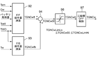
- TGNCh is calculated, and in the dehumidifying cooling mode, the cooling mode, and the air conditioning (priority) + battery cooling mode, based on the heat absorber temperature Te, the target rotation speed of the compressor 2 (compressor target rotation speed) according to the control block diagram of FIG. Calculate TGNCc.
- the dehumidifying and heating mode the lower direction of the compressor target rotation speed TGNCh and the compressor target rotation speed TGNc is selected.
- the target rotation speed of the compressor 2 (compressor target rotation speed) TGNCw is calculated based on the heat medium temperature Tw by the control block diagram of FIG. To do.
- FIG. 11 is a control block diagram of the heat pump controller 32 that calculates the target rotation speed (compressor target rotation speed) TGNCh of the compressor 2 based on the radiator pressure Pci.
- the air flow rate SW obtained by the air mix damper 28, the target supercooling degree TGSC that is the target value of the supercooling degree SC of the refrigerant at the outlet of the radiator 4, and the target heater described above that is the target value of the heater temperature Thp.
- the F / F operation amount TGNChff of the compressor target rotation speed is calculated.
- the heater temperature Thp is an air temperature (estimated value) on the leeward side of the radiator 4, and the radiator pressure Pci detected by the radiator pressure sensor 47 and the refrigerant outlet of the radiator 4 detected by the radiator outlet temperature sensor 44. It is calculated (estimated) from the temperature Tci.
- the degree of supercooling SC is calculated from the refrigerant inlet temperature Tcxin and the refrigerant outlet temperature Tci of the radiator 4 detected by the radiator inlet temperature sensor 43 and the radiator outlet temperature sensor 44.
- the target radiator pressure PCO is calculated by the target value calculator 79 based on the target supercooling degree TGSC and the target heater temperature TCO. Further, the F / B (feedback) manipulated variable calculation unit 81 calculates the F / B manipulated variable TGNChfb of the compressor target rotational speed by PID calculation or PI calculation based on the target radiator pressure PCO and the radiator pressure Pci. Then, the F / F operation amount TGNChff calculated by the F / F operation amount calculation unit 78 and the F / B operation amount TGNChfb calculated by the F / B operation amount calculation unit 81 are added by the adder 82 to obtain a limit setting unit as TGNCh00. 83 is input.
- the lower limit speed ECNpdLimLo and the upper limit speed ECNpdLimHi for control are set to TGNCh0, and then the compressor OFF control unit 84 is used to determine the target compressor speed TGNCh.
- the heat pump controller 32 controls the operation of the compressor 2 so that the radiator pressure Pci becomes the target radiator pressure PCO by the compressor target rotation speed TGNCh calculated based on the radiator pressure Pci.
- the compressor OFF control unit 84 sets the compressor target rotation speed TGNCh to the above-described lower limit rotation speed ECNpdLimLo and sets the radiator pressure Pci to a predetermined upper limit value PUL and lower limit value PLL set above and below the target radiator pressure PCO.
- the compressor 2 is stopped and the ON-OFF mode for ON-OFF controlling the compressor 2 is entered.
- the compressor 2 In the ON-OFF mode of the compressor 2, when the radiator pressure Pci decreases to the lower limit value PLL, the compressor 2 is started to operate the compressor target rotation speed TGNCh as the lower limit rotation speed ECNpdLimLo, and heat is released in that state.
- the container pressure Pci rises to the upper limit value PUL, the compressor 2 is stopped again. That is, the operation (ON) and the stop (OFF) of the compressor 2 at the lower limit rotation speed ECNpdLimLo are repeated.
- the radiator pressure Pci decreases to the lower limit value PUL and the compressor 2 is started, and the radiator pressure Pci does not become higher than the lower limit value PUL for a predetermined time th2, the compressor 2 is turned on and off. Is completed and the normal mode is restored.
- FIG. 12 is a control block diagram of the heat pump controller 32 that calculates the target rotation speed (compressor target rotation speed) TGNCc of the compressor 2 based on the heat absorber temperature Te.
- the F / F operation amount calculation unit 86 of the heat pump controller 32 has an outside air temperature Tam, an air flow amount Ga of air flowing through the air flow passage 3 (may be a blower voltage BLV of the indoor blower 27), a target radiator pressure PCO, The F / F operation amount TGNCcff of the compressor target rotation speed is calculated based on the target heat absorber temperature TEO which is the target value of the heat absorber temperature Te.
- the F / B manipulated variable calculation unit 87 also calculates the F / B manipulated variable TGNCcfb of the compressor target rotation speed by PID calculation or PI calculation based on the target heat absorber temperature TEO and the heat absorber temperature Te. Then, the F / F operation amount TGNCcff calculated by the F / F operation amount calculation unit 86 and the F / B operation amount TGNCcfb calculated by the F / B operation amount calculation unit 87 are added by the adder 88 to obtain a limit setting unit as TGNCc00. It is input to 89.
- the lower limit rotational speed TGNCcLimLo and the upper limit rotational speed TGNCcLimHi for control are set to TGNCc0, and then the compressor OFF control unit 91 is used to determine the target compressor rotational speed TGNCc. Therefore, if the value TGNCc00 added by the adder 88 is within the upper limit rotational speed TGNCcLimHi and the lower limit rotational speed TGNCcLimLo and the ON-OFF mode described later does not occur, this value TGNCc00 is the target compressor rotational speed TGNCc (compressor 2 Will be the number of rotations).
- the heat pump controller 32 controls the operation of the compressor 2 so that the heat absorber temperature Te becomes the target heat absorber temperature TEO by the compressor target rotation speed TGNCc calculated based on the heat absorber temperature Te.
- the compressor OFF control unit 91 determines that the compressor target rotation speed TGNCc becomes the above-described lower limit rotation speed TGNCcLimLo, and the heat absorber temperature Te is set between the upper limit value TeUL and the lower limit value TeLL set above and below the target heat sink temperature TEO.
- the compressor 2 is stopped and the ON-OFF mode in which the compressor 2 is ON-OFF controlled is entered.
- FIG. 14 is a control block diagram of the heat pump controller 32 that calculates the target rotation speed (compressor target rotation speed) TGNCw of the compressor 2 based on the heat medium temperature Tw.
- the F / F operation amount calculation unit 92 of the heat pump controller 32 uses the outside air temperature Tam, the flow rate Gw of the heat medium in the device temperature adjustment device 61 (calculated from the output of the circulation pump 62), and the heat generation amount of the battery 55 (battery).
- the F / B operation amount calculation unit 93 performs the PID calculation or the PI calculation based on the target heat medium temperature TWO and the heat medium temperature Tw (transmitted from the battery controller 73) to perform the F / B operation amount TGNCwfb of the compressor target rotation speed. To calculate. Then, the F / F operation amount TGNCwff calculated by the F / F operation amount calculation unit 92 and the F / B operation amount TGNCwfb calculated by the F / B operation amount calculation unit 93 are added by the adder 94 to obtain a limit setting unit as TGNCw00. 96 is input.
- the lower limit speed TGNCwLimLo for control and the upper limit speed TGNCwLimHi are set to TGNCw0, and then the compressor OFF control unit 97 is used to determine the target compressor speed TGNCw. Therefore, if the value TGNCw00 added by the adder 94 is within the upper limit rotation speed TGNCwLimHi and the lower limit rotation speed TGNCwLimLo and the ON-OFF mode described later does not occur, this value TGNCw00 is the target compressor rotation speed TGNCw (compressor 2 Will be the number of rotations). In the normal mode, the heat pump controller 32 controls the operation of the compressor 2 so that the heat medium temperature Tw becomes the target heat medium temperature TWO by the compressor target rotation speed TGNCw calculated based on the heat medium temperature Tw.
- the compressor OFF control unit 97 determines that the compressor target rotation speed TGNCw becomes the above-described lower limit rotation speed TGNCwLimLo, and the heat medium temperature Tw is the upper limit value TwUL and the lower limit value TwLL set above and below the target heat medium temperature TWO.
- the compressor 2 is stopped and the ON-OFF mode for ON-OFF controlling the compressor 2 is entered.
- the compressor 2 In the ON-OFF mode of the compressor 2 in this case, when the heat medium temperature Tw rises to the upper limit value TwUL, the compressor 2 is started and the compressor target rotation speed TGNCw is operated as the lower limit rotation speed TGNCwLimLo, and the state is maintained. If the heat medium temperature Tw has dropped to the lower limit value TwLL, the compressor 2 is stopped again. That is, the operation (ON) and the stop (OFF) of the compressor 2 at the lower limit rotation speed TGNCwLimLo are repeated.
- the battery cooling (single) mode the battery cooling (priority) + air conditioning mode, the air conditioning (priority) + battery cooling mode, and the battery Execution of heating mode (these are the first operation mode) is prohibited (not permitted), and execution of heating mode, dehumidification heating mode, dehumidification cooling mode, cooling mode, defrost mode (these are the second operation modes) Allow (second row from the top in Fig. 16).
- the abnormality relating to the battery temperature control information (information necessary for temperature control of the battery (object to be temperature controlled)) transmitted from the air conditioning controller 45 is one of the following in the embodiment, or , Their combination, or all of them.
- Iii) Abnormality of information of heat medium temperature Tw and battery temperature Tcell (disconnection / short circuit / absorption of heat medium temperature sensor 76 and battery temperature sensor 77)
- the heat pump controller 32 can electrically detect the disconnection / short circuit abnormality.
- the attachment abnormality of the heat medium temperature sensor 76 and the battery temperature sensor 77 is a case where the respective sensors are not attached to the attachment location and are detached, for example, during operation, or after a predetermined time has elapsed after the start of operation. However, it can be detected because the detected value does not change more than the predetermined value.
- the operation information of the solenoid valve (for cabin) 35 is abnormal, the inflow of the refrigerant into the heat absorber 9 cannot be controlled. Therefore, in the second stage of FIG. 16, only the heating mode described above is used. Will be allowed.
- the heat pump controller 32 performs each air conditioning operation of the heating mode, the dehumidification heating mode, the dehumidification cooling mode, the cooling mode, and the air conditioning (priority) + battery cooling mode, and the battery cooling (priority). ) + Prohibit (not allow) the execution of the air conditioning mode and the defrosting mode (third stage from the top in FIG. 16).
- the HP control information includes operation information of the compressor 2 other than the above, each of the blowers 15, 27, each of the dampers 26, 28, 31, the auxiliary heater 23, the temperature, the humidity, and the pressure other than the above.
- Sensor information relating to carbon dioxide concentration and the like which is information necessary for air conditioning of the vehicle interior, which is input to the heat pump controller 32.
- the heat pump controller 32 permits execution of only the battery heating mode (third stage in FIG. 16). Part of the battery cooling (single) mode is permitted (third stage in FIG. 16). The partial permission of the battery cooling (single) mode in this case is necessary for air conditioning of the vehicle interior of the vehicle such as the indoor blower 27 and the heat absorber temperature sensor 48, but is not necessary in the battery cooling (single) mode. If the HP control information is abnormal, execution is permitted. Further, when both the HP control information and the battery temperature control information are abnormal (bottom row in FIG. 16), execution (non-permission) of all operation modes is prohibited.
- the heat pump controller 32 when an abnormality related to the battery temperature control information (information necessary for temperature control of the temperature controlled target) occurs, the battery cooling (single) mode, the battery cooling (priority) + air conditioning mode, the air conditioning (Priority) + Battery cooling mode and battery heating mode (these are the first operation modes) are prohibited from execution, and heating mode, dehumidification heating mode, dehumidification cooling mode, cooling mode, defrost mode (these are the second operation modes) Mode) is allowed.
- the battery cooling (single) mode, the battery cooling (priority) + air conditioning mode, the air conditioning (Priority) + Battery cooling mode and battery heating mode (these are the first operation modes) are prohibited from execution, and heating mode, dehumidification heating mode, dehumidification cooling mode, cooling mode, defrost mode (these are the second operation modes) Mode) is allowed.
- the temperature control of the battery 55 can be stopped and the air conditioning in the vehicle interior can be continued.
- passenger comfort and safety can be ensured.
- the battery temperature control information is the battery cooling request / battery heating request as the temperature control request of the temperature controlled object, the operation information of the solenoid valve (for cabin) 35 and the solenoid valve (for chiller) 69, the heat medium temperature. Since the information of Tw and the battery temperature Tcell, the abnormality of the operation information of the circulation pump 62, and the abnormality of the operation information of the heat medium heating heater 63 are included in the communication of the information, the communication of the battery temperature control information is performed. It becomes possible to continue air conditioning in the vehicle compartment even when there is a disruption.
- the heat pump controller 32 recognizes the vehicle air conditioner that does not have the temperature control function of the battery 55 by not inputting the battery temperature control information, the vehicle air conditioner that does not have the temperature control function of the battery 55. There is no need to prepare separate heat pump controllers 32 for the device, that is, the vehicle air conditioner that does not include the device temperature adjusting device 61 and the vehicle air conditioner 1 that includes the device temperature adjusting device 61 as in the embodiment. There is also an advantage that the heat pump controller 32 (at least a part of the control device 11) can be shared between the vehicle air conditioners.
- the heat pump controller 32 is necessary for air conditioning in the vehicle interior, but when an abnormality regarding information that is not necessary for the temperature control of the battery 55 occurs, the heating mode, the dehumidifying and heating mode, the dehumidifying and cooling mode, the cooling mode, the deactivating Execution of the frost mode (these are the second operation modes) is prohibited, and execution of the battery heating mode and the battery cooling (single) mode (these are the first operation modes) is permitted (in the case of the battery cooling (single) mode, However, even if an abnormality related to information that is not necessary for the temperature control of the battery 55 occurs, the air conditioning in the vehicle compartment is stopped and the battery 55 is not allowed. The temperature control can be continued, and the safety of the battery 55 can be ensured.
- the air conditioning (priority) + battery cooling mode, the battery cooling (priority) air conditioning mode, and the battery cooling (single) mode can be executed, so that the vehicle can be operated depending on the situation.
- the air conditioning in the room and the cooling of the battery 55 can be appropriately performed without any trouble.
- the heating mode, the dehumidifying heating mode, the dehumidifying cooling mode, the cooling mode, and the defrosting mode can be executed, so that even when an abnormality related to the battery temperature control information occurs, It becomes possible to realize comfortable air conditioning in the room.
- the device-temperature adjusting device 61 causes the refrigerant-heat medium heat exchanger 64 for exchanging heat between the refrigerant and the heat medium, the heat medium heater 63, and heat between them and the battery 55.
- the circulation pump 62 for circulating the medium, the heat medium can be cooled / heated by using the refrigerant, and the battery 55 can be smoothly heated / cooled via the heat medium.
- the heat medium temperature Tw is adopted as the temperature of the target (heat medium) cooled by the refrigerant-heat medium heat exchanger 64 (heat exchanger for temperature control), but the battery temperature Tcell is used. It may be adopted as the temperature of the object to be cooled by the refrigerant-heat medium heat exchanger 64 (heat exchanger for temperature control), and the temperature of the refrigerant-heat medium heat exchanger 64 (refrigerant-heat medium heat exchanger) The temperature of 64 itself, the temperature of the refrigerant flowing out of the refrigerant channel 64B, etc.) may be adopted as the temperature of the refrigerant-heat medium heat exchanger 64 (heat exchanger for temperature adjustment).
- the heat medium is circulated to control the temperature of the battery 55.
- the invention other than claim 7 is not limited to this, and the refrigerant and the battery 55 (object to be temperature-controlled) are directly heat-exchanged.
- a heat exchanger for temperature control may be provided. In that case, the battery temperature Tcell becomes the temperature of the target to be cooled by the target heat exchanger for temperature adjustment.
- the vehicle 55 is capable of cooling the battery 55 while cooling the vehicle interior in the air conditioning (priority) + battery cooling mode and the battery cooling (priority) + air conditioning mode for simultaneously cooling the vehicle interior and cooling the battery 55.
- the air conditioning apparatus 1 has been described, the cooling of the battery 55 is not limited to during cooling, but other air conditioning operation, for example, the above-described dehumidifying and heating operation and cooling of the battery 55 may be performed simultaneously.
- the solenoid valve 69 is opened, and a part of the refrigerant flowing toward the heat absorber 9 via the refrigerant pipe 13F is caused to flow into the branch pipe 67 and flow into the refrigerant-heat medium heat exchanger 64.
- the electromagnetic valve 35 is the heat absorber valve device (valve device) and the electromagnetic valve 69 is the temperature controlled valve device (valve device), but the indoor expansion valve 8 and the auxiliary expansion valve 68 can be fully closed.
- the solenoid valves 35 and 69 are not required, the indoor expansion valve 8 serves as the heat absorber valve device of the present invention, and the auxiliary expansion valve 68 serves as the temperature controlled valve device.
- the configuration and numerical values of the refrigerant circuit R described in the embodiments are not limited thereto and can be changed without departing from the spirit of the present invention.
- the present invention has been described with the vehicle air conditioner 1 having each operation mode such as the heating mode, the dehumidification heating mode, the dehumidification cooling mode, the cooling mode, the air conditioning (priority) + battery cooling mode, but the present invention is not limited thereto.
- any one of the first operation modes in which the temperature of the battery 55 is adjusted and any one of the second operation modes in which the temperature of the battery 55 is not adjusted for example, cooling mode, air conditioning (priority) + battery cooling mode
- the present invention is also effective for a vehicle air conditioner capable of executing only battery cooling (priority) + air conditioning mode.
Abstract
[Problem] To provide a vehicle air-conditioning device capable of continuing to condition the air inside a vehicle compartment without failure, even when an abnormality occurs which pertains to information required for temperature control of a temperature control target installed in the vehicle. [Solution] The present invention is equipped with a device temperature adjustment apparatus 61 for adjusting the temperature of a battery 55 installed in a vehicle. Meanwhile, a control device (heat pump controller) has a first operation mode for controlling the temperature of the battery 55 using the device temperature adjustment apparatus, and a second operation mode which does not perform a battery 55 temperature control. When there is an abnormality in the information required for the battery 55 temperature control, execution of the first operation mode is prohibited and execution of the second operation mode is permitted.
Description
本発明は、車両の車室内を空調するヒートポンプ方式の空気調和装置、特に車両に搭載された被温調対象の温調も行うことができるものに関する。
The present invention relates to a heat pump type air conditioner that air-conditions the interior of a vehicle, and in particular, to a device that is mounted on a vehicle and can also control the temperature of a temperature-controlled object.
近年の環境問題の顕在化から、車両に搭載されたバッテリから供給される電力で走行用モータを駆動する電気自動車やハイブリッド自動車等の車両が普及するに至っている。そして、このような車両に適用することができる空気調和装置として、圧縮機と、放熱器と、吸熱器と、室外熱交換器が接続された冷媒回路を備え、圧縮機から吐出された冷媒を放熱器において放熱させ、この放熱器において放熱した冷媒を室外熱交換器において吸熱させることで暖房し、圧縮機から吐出された冷媒を室外熱交換器において放熱させ、吸熱器(蒸発器)において蒸発させ、吸熱させることで冷房する等して車室内を空調するものが開発されている(例えば、特許文献1参照)。
Due to the emergence of environmental problems in recent years, vehicles such as electric vehicles and hybrid vehicles that drive a traveling motor with electric power supplied from a battery mounted on the vehicle have come into widespread use. Then, as an air conditioner that can be applied to such a vehicle, a compressor, a radiator, a heat absorber, and an outdoor heat exchanger are provided with a refrigerant circuit, and the refrigerant discharged from the compressor is provided. The radiator dissipates heat, and the refrigerant dissipated in this radiator absorbs heat in the outdoor heat exchanger to heat it. The refrigerant discharged from the compressor dissipates heat in the outdoor heat exchanger and evaporates in the heat absorber (evaporator). An air conditioner has been developed to cool the interior of the vehicle by absorbing heat and cooling the air (for example, see Patent Document 1).
一方、例えばバッテリ等は充放電による自己発熱等で高温となった環境下で充放電を行うと劣化が進行し、やがては作動不良を起こして破損する危険性がある。また、低温環境下でも充放電性能が低下する。そこで、冷媒回路にバッテリ用の熱交換器を別途設け、冷媒回路を循環する冷媒とバッテリ用冷媒(熱媒体)とをこのバッテリ用の熱交換器で熱交換させ、この熱交換した熱媒体をバッテリに循環させることでバッテリを冷却することができる機能を有したものも開発されている(例えば、特許文献2、特許文献3参照)。
On the other hand, for example, when batteries are charged and discharged in an environment where the temperature is high due to self-heating due to charging and discharging, deterioration progresses, and there is a risk that they will eventually malfunction and be damaged. Also, the charge / discharge performance is reduced even in a low temperature environment. Therefore, a heat exchanger for the battery is separately provided in the refrigerant circuit, the refrigerant circulating in the refrigerant circuit and the refrigerant (heat medium) for the battery are heat-exchanged by the heat exchanger for the battery, and the heat medium thus heat-exchanged is used. A device having a function of cooling the battery by circulating it in the battery has also been developed (see, for example, Patent Documents 2 and 3).
ここで、従来では上記のようなバッテリ(被温調対象)の冷却(温調)に必要な情報に関する異常(センサの異常、機器の異常)が発生した場合、車両用空気調和装置を停止していたため、車室内の空調も行われなくなり、乗員の快適性と安全性が損なわれてしまうという問題があった。
Here, conventionally, when an abnormality (sensor abnormality, equipment abnormality) related to information necessary for cooling (temperature adjustment) of a battery (object to be temperature-controlled) as described above occurs, the vehicle air conditioner is stopped. Therefore, there is a problem that the passenger compartment is not air-conditioned and the comfort and safety of passengers are impaired.
本発明は、係る従来の技術的課題を解決するために成されたものであり、車両に搭載された被温調対象の温調に必要な情報に関して異常が発生した場合にも、支障無く車室内の空調を継続することができる車両用空気調和装置を提供することを目的とする。
The present invention has been made in order to solve the above-mentioned conventional technical problems, and when an abnormality occurs in the information necessary for the temperature control of the temperature-controlled object mounted on the vehicle, the vehicle can be safely operated. It is an object of the present invention to provide an air conditioning system for a vehicle that can continue air conditioning in a room.
本発明の車両用空気調和装置は、冷媒を圧縮する圧縮機と、車室内に供給する空気と冷媒を熱交換させるための室内熱交換器と、車室外に設けられた室外熱交換器と、制御装置を備えて車室内を空調するものであって、車両に搭載された被温調対象の温度を調整するための機器温度調整装置を備え、制御装置は、機器温度調整装置により被温調対象の温調を行う第1の運転モードと、被温調対象の温調を行わない第2の運転モードを有し、被温調対象の温調に必要な情報に関する異常が発生した場合、第1の運転モードの実行を禁止し、第2の運転モードの実行は許可することを特徴とする。
The vehicle air conditioner of the present invention is a compressor that compresses the refrigerant, an indoor heat exchanger for exchanging heat between the air supplied to the passenger compartment and the refrigerant, and an outdoor heat exchanger provided outside the passenger compartment, A device for air conditioning the interior of the vehicle equipped with a control device, which is equipped with a device temperature adjustment device mounted on the vehicle for adjusting the temperature of an object to be temperature controlled, and the control device is controlled by the device temperature adjustment device. When there is a first operation mode in which the temperature control of the target is performed and a second operation mode in which the temperature control of the temperature controlled target is not performed, and an abnormality related to information necessary for the temperature control of the temperature controlled target occurs, It is characterized in that the execution of the first operation mode is prohibited and the execution of the second operation mode is permitted.
請求項2の発明の車両用空気調和装置は、被温調対象の温調に必要な情報は、被温調対象を温調するための熱媒体の温度と、被温調対象の温度と、熱媒体を被温調対象に循環させるための循環装置の作動状態と、被温調対象を冷却するための被温調対象用熱交換器に冷媒を流しているときに、室内熱交換器への冷媒の流通を制御するための室内熱交換器用弁装置の作動状態と、被温調対象用熱交換器への冷媒の流通を制御するための被温調対象用弁装置の作動状態と、被温調対象の温調要求のうちの何れか、或いは、それらの組み合わせ、若しくは、それらの全てであることを特徴とする。
In the vehicle air conditioner of the invention of claim 2, the information necessary for the temperature control of the temperature control target is the temperature of the heat medium for controlling the temperature control target, the temperature of the temperature control target, When the refrigerant is flowing through the operating condition of the circulation device for circulating the heat medium to the temperature controlled object and the heat exchanger for the temperature controlled object for cooling the temperature controlled object, to the indoor heat exchanger The operating state of the indoor heat exchanger valve device for controlling the flow of the refrigerant, the operating state of the temperature control target valve device for controlling the flow of the refrigerant to the temperature control target heat exchanger, It is characterized in that it is any one of the temperature control requests of the temperature controlled object, a combination thereof, or all of them.
請求項3の発明の車両用空気調和装置は、上記各発明において被温調対象の温調に必要な情報に関する異常には、当該情報の通信途絶を含むことを特徴とする。
The vehicle air conditioner according to the invention of claim 3 is characterized in that, in each of the above inventions, the abnormality related to the information necessary for the temperature control of the object to be temperature controlled includes the communication interruption of the information.
請求項4の発明の車両用空気調和装置は、冷媒を圧縮する圧縮機と、車室内に供給する空気と冷媒を熱交換させるための室内熱交換器と、車室外に設けられた室外熱交換器と、制御装置を備えて車室内を空調するものであって、車両に搭載された被温調対象の温度を調整するための機器温度調整装置を備え、制御装置は、機器温度調整装置により被温調対象の温調を行う第1の運転モードと、被温調対象の温調を行わない第2の運転モードを有し、車室内の空調に必要であるが、被温調対象の温調には必要ではない情報に関する異常が発生した場合、第2の運転モードの実行を禁止し、第1の運転モードの実行は許可することを特徴とする。
The vehicle air conditioner according to the invention of claim 4 is a compressor for compressing a refrigerant, an indoor heat exchanger for exchanging heat between the air supplied to the passenger compartment and the refrigerant, and an outdoor heat exchanger provided outside the passenger compartment. And a control device for air conditioning the interior of the vehicle, which is equipped with a device temperature adjusting device for adjusting the temperature of the temperature-controlled object mounted on the vehicle, and the control device is configured by the device temperature adjusting device. It has a first operation mode in which the temperature of the temperature-controlled object is adjusted and a second operation mode in which the temperature of the temperature-controlled object is not adjusted. When an abnormality relating to information that is not necessary for temperature control occurs, execution of the second operation mode is prohibited and execution of the first operation mode is permitted.
請求項5の発明の車両用空気調和装置は、上記各発明において室内熱交換器は、冷媒を吸熱させて車室内に供給する空気を冷却するための吸熱器であり、機器温度調整装置は、冷媒を吸熱させて被温調対象を冷却するための被温調対象用熱交換器を有し、制御装置が実行する第1の運転モードは、圧縮機から吐出された冷媒を室外熱交換器にて放熱させ、放熱した当該冷媒を減圧した後、吸熱器と被温調対象用熱交換器にて吸熱させる空調+被温調対象冷却モードと、圧縮機から吐出された冷媒を室外熱交換器にて放熱させ、放熱した当該冷媒を減圧した後、被温調対象用熱交換器にて吸熱させる被温調対象冷却(単独)モードのうちの何れか、又は、双方を含むことを特徴とする。
In the vehicle air conditioner of the invention of claim 5, in each of the above inventions, the indoor heat exchanger is a heat absorber for absorbing the refrigerant to cool the air supplied to the vehicle interior, and the device temperature adjusting device is: The first operation mode executed by the control device has a heat exchanger for temperature controlled, which cools the target to be temperature controlled by absorbing the heat of the refrigerant, and the first operation mode executed by the control device is that the refrigerant discharged from the compressor is the outdoor heat exchanger. Heat-dissipating the refrigerant, decompressing the heat-dissipated refrigerant, and then absorbing the heat in the heat absorber and the heat exchanger for temperature-controlled air-conditioning + cooling mode for the temperature-controlled air-conditioning and the refrigerant discharged from the compressor for outdoor heat exchange. It is characterized by including either or both of the temperature controlled cooling (single) modes in which the heat is dissipated by the heat exchanger and the heat-dissipated refrigerant is decompressed and then absorbed by the heat exchanger for temperature controlled And
請求項6の発明の車両用空気調和装置は、上記発明において被温調対象用熱交換器に冷媒を流しているときに、吸熱器への冷媒の流通を制御するための室内熱交換器用弁装置と、被温調対象用熱交換器への冷媒の流通を制御するための被温調対象用弁装置を備え、空調+被温調対象冷却モードは、室内熱交換器用弁装置を開き、吸熱器又はそれにより冷却される対象の温度に基づいて圧縮機の回転数を制御し、被温調対象用熱交換器又はそれにより冷却される対象の温度に基づいて被温調対象用弁装置を開閉制御する空調(優先)+被温調対象冷却モードと、被温調対象用弁装置を開き、被温調対象用熱交換器又はそれにより冷却される対象の温度に基づいて圧縮機の回転数を制御し、吸熱器又はそれにより冷却される対象の温度に基づいて室内熱交換器用弁装置を開閉制御する被温調対象冷却(優先)+空調モードを含むことを特徴とする。
The vehicle air conditioner according to a sixth aspect of the present invention is the valve for an indoor heat exchanger for controlling the flow of the refrigerant to the heat absorber when the refrigerant is flowing through the heat exchanger for temperature adjustment in the above invention. A device and a valve device for the temperature controlled object for controlling the flow of the refrigerant to the heat exchanger for the temperature controlled object, the air conditioning + the temperature controlled target cooling mode, open the valve device for the indoor heat exchanger, The rotation speed of the compressor is controlled based on the temperature of the heat absorber or the object cooled by the heat absorber, and the valve device for the temperature controlled object is controlled based on the temperature of the heat exchanger for the temperature controlled object or the object cooled by the heat exchanger. Opening / closing control of air conditioning (priority) + temperature control target cooling mode, and opening the temperature control target valve device, and based on the temperature of the temperature control target heat exchanger or the temperature of the target cooled by the compressor It is characterized by including a controlled temperature target cooling (priority) + air conditioning mode in which the rotation speed is controlled, and the indoor heat exchanger valve device is opened / closed based on the temperature of the heat absorber or the object cooled by it.
請求項7の発明の車両用空気調和装置は、上記各発明において冷媒を放熱させて車室内に供給する空気を加熱するためのもう一つの室内熱交換器としての放熱器を備え、制御装置が実行する第2の運転モードは、圧縮機から吐出された冷媒を放熱器にて放熱させ、放熱した当該冷媒を減圧した後、室外熱交換器にて吸熱させる暖房モードと、圧縮機から吐出された冷媒を放熱器にて放熱させ、放熱した当該冷媒を減圧した後、吸熱器にて吸熱させる除湿モードと、圧縮機から吐出された冷媒を室外熱交換器にて放熱させ、放熱した当該冷媒を減圧した後、吸熱器にて吸熱させる冷房モードと、圧縮機から吐出された冷媒を室外熱交換器にて放熱させて当該室外熱交換器を除霜する除霜モードのうちの何れか、或いは、それらの組み合わせ、若しくは、それらの全てであることを特徴とする。
A vehicle air conditioner according to a seventh aspect of the present invention includes a radiator as another indoor heat exchanger for radiating the refrigerant to heat the air supplied to the passenger compartment in each of the above inventions. The second operation mode to be executed is a heating mode in which the refrigerant discharged from the compressor is radiated by the radiator, the radiated refrigerant is decompressed, and the heat is absorbed by the outdoor heat exchanger, and the second operation mode is discharged from the compressor. The refrigerant is radiated by the radiator, the decompressed refrigerant is decompressed, and the dehumidifying mode in which the heat is absorbed by the heat absorber, and the refrigerant discharged from the compressor is radiated by the outdoor heat exchanger, and the refrigerant is radiated. After depressurizing, the cooling mode to absorb heat in the heat absorber, one of the defrosting mode to defrost the outdoor heat exchanger by radiating the refrigerant discharged from the compressor in the outdoor heat exchanger, Alternatively, it is characterized by a combination thereof or all of them.
請求項8の発明の車両用空気調和装置は、上記各発明において機器温度調整装置は、冷媒と熱媒体とを熱交換させるための被温調対象用熱交換器と、この被温調対象用熱交換器と被温調対象との間で熱媒体を循環させるための循環装置を有することを特徴とする。
In the vehicle air conditioner of the invention of claim 8, in each of the above inventions, the device temperature adjusting device is a heat exchanger for temperature-controlled object for exchanging heat between a refrigerant and a heat medium, and for this temperature-controlled object. It is characterized by having a circulation device for circulating the heat medium between the heat exchanger and the temperature-controlled object.
請求項9の発明の車両用空気調和装置は、請求項1乃至請求項3の発明において機器温度調整装置は、被温調対象を加熱するための加熱装置を備え、制御装置は、第1の運転モードとして、加熱装置により被温調対象を加熱する被温調対象加熱モードを有し、被温調対象の温調に必要な情報には加熱装置の作動状態を含むことを特徴とする。
A vehicle air conditioner according to a ninth aspect of the present invention is the vehicle temperature control apparatus according to any of the first to third aspects, wherein the device temperature adjustment device includes a heating device for heating an object to be temperature-controlled, and the control device includes the first device. The operation mode includes a temperature-controlled object heating mode for heating the temperature-controlled object by the heating device, and the information required for temperature control of the temperature-controlled object includes the operating state of the heating device.
請求項1の発明によれば、冷媒を圧縮する圧縮機と、車室内に供給する空気と冷媒を熱交換させるための室内熱交換器と、車室外に設けられた室外熱交換器と、制御装置を備えて車室内を空調する車両用空気調和装置において、車両に搭載された被温調対象の温度を調整するための機器温度調整装置を備え、制御装置が、機器温度調整装置により被温調対象の温調を行う第1の運転モードと、被温調対象の温調を行わない第2の運転モードを有し、被温調対象の温調に必要な情報に関する異常が発生した場合、第1の運転モードの実行を禁止し、第2の運転モードの実行は許可するようにしたので、被温調対象の温調に必要な情報に関する異常が発生したときにも、被温調対象の温調を停止し、車室内の空調は継続することができるようになり、乗員の快適性と安全性を確保することができるようになる。
According to the invention of claim 1, a compressor for compressing the refrigerant, an indoor heat exchanger for exchanging heat between the air supplied to the passenger compartment and the refrigerant, an outdoor heat exchanger provided outside the passenger compartment, and a control An air conditioner for a vehicle, which is equipped with a device to air-condition the interior of a vehicle, is provided with a device temperature adjusting device for adjusting the temperature of an object to be temperature-controlled mounted on a vehicle, and the control device controls the temperature by the device temperature adjusting device. When there is a first operation mode in which the temperature control of the temperature control target is performed and a second operation mode in which the temperature control of the temperature control target is not performed, and an abnormality related to information necessary for the temperature control of the temperature control target occurs. Since the execution of the first operation mode is prohibited and the execution of the second operation mode is permitted, even when an abnormality related to the information necessary for temperature control of the temperature control target occurs, the temperature control is performed. The temperature control of the target can be stopped and the air conditioning in the passenger compartment can be continued, so that the comfort and safety of the occupant can be secured.
この場合、被温調対象の温調に必要な情報とは、請求項2の発明の如く、被温調対象を温調するための熱媒体の温度と、被温調対象の温度と、熱媒体を被温調対象に循環させるための循環装置の作動状態と、被温調対象を冷却するための被温調対象用熱交換器に冷媒を流しているときに、室内熱交換器への冷媒の流通を制御するための室内熱交換器用弁装置の作動状態と、被温調対象用熱交換器への冷媒の流通を制御するための被温調対象用弁装置の作動状態と、被温調対象の温調要求のうちの何れか、或いは、それらの組み合わせ、若しくは、それらの全てが考えられる。
In this case, the information necessary for temperature control of the temperature controlled object includes the temperature of the heat medium for controlling the temperature controlled object, the temperature of the temperature controlled object, and the heat When the refrigerant is flowing in the operating state of the circulation device for circulating the medium to the temperature-controlled object and the heat exchanger for the temperature-controlled object for cooling the temperature-controlled object, the indoor heat exchanger The operating state of the valve device for the indoor heat exchanger for controlling the flow of the refrigerant, the operating state of the valve device for the temperature controlled object for controlling the flow of the refrigerant to the heat exchanger for the temperature controlled object, and Any of the temperature control requests of the temperature control target, a combination thereof, or all of them can be considered.
また、請求項3の発明の如く被温調対象の温調に必要な情報に関する異常に、当該情報の通信途絶を含むことにより、被温調対象の温調に必要な情報の通信途絶の場合にも車室内の空調を継続することができるようになると共に、被温調対象の温調機能が無い装置、即ち、機器温度調整装置を搭載しない車両用空気調和装置と、搭載した車両用空気調和装置との間で制御装置の少なくとも一部を共通化できる利点もある。
Further, in the case of the communication interruption of the information necessary for the temperature control of the temperature controlled object by including the communication interruption of the information necessary for the temperature control of the temperature controlled object as in the invention of claim 3, In addition, it becomes possible to continue air conditioning in the vehicle interior, and a device that does not have a temperature control function for the temperature-controlled object, that is, a vehicle air conditioner that does not include a device temperature adjustment device, and an installed vehicle air conditioner. There is also an advantage that at least a part of the control device can be shared with the harmony device.
請求項4の発明によれば、冷媒を圧縮する圧縮機と、車室内に供給する空気と冷媒を熱交換させるための室内熱交換器と、車室外に設けられた室外熱交換器と、制御装置を備えて車室内を空調する車両用空気調和装置において、車両に搭載された被温調対象の温度を調整するための機器温度調整装置を備え、制御装置が、機器温度調整装置により被温調対象の温調を行う第1の運転モードと、被温調対象の温調を行わない第2の運転モードを有し、車室内の空調に必要であるが、被温調対象の温調には必要ではない情報に関する異常が発生した場合、第2の運転モードの実行を禁止し、第1の運転モードの実行は許可するようにしたので、車室内の空調に必要であるが、被温調対象の温調には必要ではない情報に関する異常が発生したときにも、車室内の空調は停止し、被温調対象の温調は継続することができるようになり、被温調対象の安全性を確保することができるようになる。
According to the invention of claim 4, a compressor for compressing the refrigerant, an indoor heat exchanger for exchanging heat between the air supplied to the passenger compartment and the refrigerant, an outdoor heat exchanger provided outside the passenger compartment, and a control An air conditioner for a vehicle, which is equipped with a device to air-condition the interior of a vehicle, is provided with a device temperature adjusting device for adjusting the temperature of an object to be temperature-controlled mounted on a vehicle, and the control device controls the temperature by the device temperature adjusting device. It has a first operation mode in which the temperature control of the temperature control target is performed and a second operation mode in which the temperature control of the temperature control target is not performed. When an abnormality relating to information that is not necessary for the operation occurs, the execution of the second operation mode is prohibited, and the execution of the first operation mode is allowed. Even if an abnormality occurs in the information that is not necessary for the temperature control of the temperature control target, the air conditioning in the passenger compartment is stopped, and the temperature control of the temperature control target can be continued. Will be able to ensure the safety of.
そして、請求項5の発明の如く室内熱交換器を、冷媒を吸熱させて車室内に供給する空気を冷却するための吸熱器とし、機器温度調整装置が、冷媒を吸熱させて被温調対象を冷却するための被温調対象用熱交換器を有するようにし、制御装置が実行する第1の運転モードが、圧縮機から吐出された冷媒を室外熱交換器にて放熱させ、放熱した当該冷媒を減圧した後、吸熱器と被温調対象用熱交換器にて吸熱させる空調+被温調対象冷却モードと、圧縮機から吐出された冷媒を室外熱交換器にて放熱させ、放熱した当該冷媒を減圧した後、被温調対象用熱交換器にて吸熱させる被温調対象冷却(単独)モードのうちの何れか、又は、双方を含むようにすることで、車室内の空調と被温調対象の冷却を支障無く行うことができるようになる。
Then, as in the invention of claim 5, the indoor heat exchanger is used as a heat absorber for absorbing the refrigerant to cool the air to be supplied to the vehicle interior, and the device temperature adjusting device absorbs the refrigerant to control the temperature to be controlled. The first operation mode executed by the control device is such that the heat exchanger for the temperature-controlled object for cooling the refrigerant is discharged, and the refrigerant discharged from the compressor is radiated by the outdoor heat exchanger, and the heat is radiated. After depressurizing the refrigerant, the heat sink and the heat exchanger for temperature control target heat absorption, and the cooling mode for the temperature control target, and the refrigerant discharged from the compressor is radiated by the outdoor heat exchanger and radiated. After decompressing the refrigerant, either the temperature controlled cooling (single) mode of absorbing heat in the temperature controlled heat exchanger, or by including both, air conditioning of the vehicle interior and It becomes possible to cool the temperature-controlled object without any trouble.
更に、請求項6の発明の如く被温調対象用熱交換器に冷媒を流しているときに、吸熱器への冷媒の流通を制御するための室内熱交換器用弁装置と、被温調対象用熱交換器への冷媒の流通を制御するための被温調対象用弁装置を設け、空調+被温調対象冷却モードが、室内熱交換器用弁装置を開き、吸熱器又はそれにより冷却される対象の温度に基づいて圧縮機の回転数を制御し、被温調対象用熱交換器又はそれにより冷却される対象の温度に基づいて被温調対象用弁装置を開閉制御する空調(優先)+被温調対象冷却モードと、被温調対象用弁装置を開き、被温調対象用熱交換器又はそれにより冷却される対象の温度に基づいて圧縮機の回転数を制御し、吸熱器又はそれにより冷却される対象の温度に基づいて室内熱交換器用弁装置を開閉制御する被温調対象冷却(優先)+空調モードを含むようにすれば、状況に応じて車室内の冷房と被温調対象の冷却を適切に行うことができるようになる。
Further, when the refrigerant is flowing through the heat exchanger for temperature adjustment as in the invention of claim 6, an indoor heat exchanger valve device for controlling the flow of the refrigerant to the heat absorber, and an object for temperature adjustment. A temperature controlled valve device for controlling the flow of the refrigerant to the heat exchanger is installed, and the air conditioning + controlled temperature cooling mode opens the indoor heat exchanger valve device and is cooled by the heat absorber or it. The speed of the compressor is controlled based on the temperature of the target to be controlled, and the air conditioner that controls the opening and closing of the temperature controlled target heat exchanger or the temperature of the target controlled valve device is controlled (priority ) + Temperature control target cooling mode, the temperature control target valve device is opened, and the number of revolutions of the compressor is controlled based on the temperature of the temperature control target heat exchanger or the temperature of the target cooled by the heat control target heat absorption. If the temperature control target cooling (priority) that controls the opening / closing of the valve device for the indoor heat exchanger based on the temperature of the device or the object to be cooled thereby + priority mode is included, the vehicle interior can be cooled according to the situation. It becomes possible to appropriately cool the temperature-controlled object.
尚、請求項7の発明の如く冷媒を放熱させて車室内に供給する空気を加熱するためのもう一つの室内熱交換器としての放熱器を設け、制御装置が実行する第2の運転モードを、圧縮機から吐出された冷媒を放熱器にて放熱させ、放熱した当該冷媒を減圧した後、室外熱交換器にて吸熱させる暖房モードと、圧縮機から吐出された冷媒を放熱器にて放熱させ、放熱した当該冷媒を減圧した後、吸熱器にて吸熱させる除湿モードと、圧縮機から吐出された冷媒を室外熱交換器にて放熱させ、放熱した当該冷媒を減圧した後、吸熱器にて吸熱させる冷房モードと、圧縮機から吐出された冷媒を室外熱交換器にて放熱させて当該室外熱交換器を除霜する除霜モードのうちの何れか、或いは、それらの組み合わせ、若しくは、それらの全てとすることで、被温調対象の温調に必要な情報に関する異常が発生したときにも、車室内の快適な空調を実現することができるようになる。
In addition, as in the invention of claim 7, a radiator as another indoor heat exchanger for radiating the refrigerant to heat the air supplied to the vehicle interior is provided, and the second operation mode executed by the control device is set. , A heating mode in which the refrigerant discharged from the compressor is radiated by the radiator, the radiated refrigerant is decompressed, and the heat is absorbed by the outdoor heat exchanger, and the refrigerant discharged from the compressor is radiated by the radiator. Then, after depressurizing the heat-dissipated refrigerant, the dehumidifying mode in which the heat is absorbed by the heat absorber, and the refrigerant discharged from the compressor is dissipated by the outdoor heat exchanger, and the heat-dissipated refrigerant is depressurized and then transferred to the heat absorber. Either a cooling mode for absorbing heat and a defrosting mode for defrosting the outdoor heat exchanger by radiating the refrigerant discharged from the compressor in the outdoor heat exchanger, or a combination thereof, or By using all of them, it becomes possible to realize comfortable air conditioning in the vehicle compartment even when an abnormality relating to information necessary for temperature control of the temperature controlled object occurs.
また、請求項8の発明の如く機器温度調整装置が、冷媒と熱媒体とを熱交換させるための被温調対象用熱交換器と、この被温調対象用熱交換器と被温調対象との間で熱媒体を循環させるための循環装置を有するようにすれば、冷媒を用いて熱媒体を冷却し、この熱媒体を介して被温調対象を円滑に冷却することが可能となる。
Further, the equipment temperature control apparatus according to the invention of claim 8 is a heat exchanger for temperature control for exchanging heat between a refrigerant and a heat medium, and the heat exchanger for temperature control and the temperature control target. By providing a circulation device for circulating the heat medium between and, it becomes possible to cool the heat medium by using the refrigerant and smoothly cool the temperature-controlled object via the heat medium. .
更に、請求項1乃至請求項3の発明において、請求項9の発明の如く機器温度調整装置が、被温調対象を加熱するための加熱装置を備え、制御装置が、第1の運転モードとして、加熱装置により被温調対象を加熱する被温調対象加熱モードを有し、被温調対象の温調に必要な情報には加熱装置の作動状態を含むようにすれば、加熱装置により被温調対象の加熱を行えるようになると共に、この加熱装置の作動状態に関して異常が生じた場合にも、支障無く車室内の空調を継続することができるようになるものである。
Furthermore, in the inventions of claims 1 to 3, the equipment temperature adjusting device as in the invention of claim 9 includes a heating device for heating the temperature-controlled object, and the control device sets the first operation mode as If the heating device has a temperature-controlled target heating mode for heating the temperature-controlled target and the information required for temperature control of the temperature-controlled target includes the operating state of the heating device, This makes it possible to heat the temperature control target and, even when an abnormality occurs in the operating state of the heating device, it is possible to continue air conditioning in the vehicle interior without any trouble.
以下、本発明の実施の形態について、図面に基づき詳細に説明する。図1は本発明の一実施形態の車両用空気調和装置1の構成図を示している。本発明を適用する実施例の車両は、エンジン(内燃機関)が搭載されていない電気自動車(EV)であって、車両に搭載されているバッテリ55に充電された電力を走行用モータ(電動モータ。図示せず)に供給することで駆動し、走行するものであり、本発明の車両用空気調和装置1の後述する圧縮機2も、バッテリ55から供給される電力で駆動されるものとする。
Hereinafter, embodiments of the present invention will be described in detail with reference to the drawings. FIG. 1 shows a configuration diagram of a vehicle air conditioner 1 of an embodiment of the present invention. A vehicle of an embodiment to which the present invention is applied is an electric vehicle (EV) in which an engine (internal combustion engine) is not mounted, and electric power charged in a battery 55 mounted in the vehicle is used as a traveling motor (electric motor). (Not shown) to drive and run, and the compressor 2 of the vehicle air conditioner 1 of the present invention, which will be described later, is also driven by the electric power supplied from the battery 55. ..
即ち、実施例の車両用空気調和装置1は、エンジン廃熱による暖房ができない電気自動車において、冷媒回路Rを用いたヒートポンプ運転により暖房モード、除湿暖房モード、除湿冷房モード、冷房モード、除霜モード、空調(優先)+バッテリ冷却モード、バッテリ冷却(優先)+空調モード、及び、バッテリ冷却(単独)モードの各運転モードを切り換えて実行することで車室内の空調やバッテリ55の温調を行うものである。
That is, the vehicle air conditioner 1 of the embodiment is a heating mode, a dehumidification heating mode, a dehumidification cooling mode, a cooling mode, and a defrosting mode in a heat pump operation using the refrigerant circuit R in an electric vehicle that cannot be heated by engine waste heat. , The air conditioning (priority) + battery cooling mode, the battery cooling (priority) + air conditioning mode, and the battery cooling (single) mode are switched and executed to perform air conditioning in the vehicle compartment and temperature control of the battery 55. It is a thing.
尚、車両としては電気自動車に限らず、エンジンと走行用モータを供用する所謂ハイブリッド自動車にも本発明は有効である。また、実施例の車両用空気調和装置1を適用する車両は外部の充電器(急速充電器や通常の充電器)からバッテリ55に充電可能とされているものである。更に、前述したバッテリ55や走行用モータ、それを制御するインバータ等が本発明における車両に搭載された被温調対象となるが、以下の実施例ではバッテリ55を例に採り上げて説明する。
The present invention is effective not only for electric vehicles but also for so-called hybrid vehicles that use an engine and a running motor. The vehicle to which the vehicle air conditioner 1 of the embodiment is applied is one in which the battery 55 can be charged from an external charger (a quick charger or a normal charger). Further, the battery 55, the traveling motor, the inverter controlling the same, and the like described above are the objects of temperature adjustment mounted on the vehicle in the present invention, but in the following embodiments, the battery 55 will be taken as an example for description.
実施例の車両用空気調和装置1は、電気自動車の車室内の空調(暖房、冷房、除湿、及び、換気)を行うものであり、冷媒を圧縮する電動式の圧縮機2と、車室内の空気が通気循環されるHVACユニット10の空気流通路3内に設けられ、圧縮機2から吐出された高温高圧の冷媒がマフラー5と冷媒配管13Gを介して流入し、この冷媒を車室内に放熱(冷媒の熱を放出)させる室内熱交換器としての放熱器4と、暖房時に冷媒を減圧膨張させる電動弁(電子膨張弁)から成る室外膨張弁6と、冷房時には冷媒を放熱させる放熱器として機能し、暖房時には冷媒を吸熱(冷媒に熱を吸収)させる蒸発器として機能すべく冷媒と外気との間で熱交換を行わせる室外熱交換器7と、冷媒を減圧膨張させる機械式膨張弁から成る室内膨張弁8と、空気流通路3内に設けられて冷房時及び除湿時に冷媒を蒸発させて車室内外から冷媒に吸熱(冷媒に熱を吸収)させる室内熱交換器としての吸熱器9と、アキュムレータ12等が冷媒配管13により順次接続され、冷媒回路Rが構成されている。
The vehicle air conditioner 1 of the embodiment is for performing air conditioning (heating, cooling, dehumidification, and ventilation) of a vehicle interior of an electric vehicle, and an electric compressor 2 for compressing a refrigerant and an interior of the vehicle interior. The high-temperature and high-pressure refrigerant discharged from the compressor 2, which is provided in the air flow passage 3 of the HVAC unit 10 through which air is circulated by ventilation, flows in through the muffler 5 and the refrigerant pipe 13G, and radiates this refrigerant into the vehicle interior. As a radiator 4 as an indoor heat exchanger (to release the heat of the refrigerant), an outdoor expansion valve 6 consisting of a motor-operated valve (electronic expansion valve) for decompressing and expanding the refrigerant during heating, and as a radiator for radiating the refrigerant during cooling An outdoor heat exchanger 7 that functions and performs heat exchange between the refrigerant and the outside air so as to function as an evaporator that absorbs the refrigerant (absorbs heat into the refrigerant) during heating, and a mechanical expansion valve that decompresses and expands the refrigerant. And an indoor expansion valve 8 made up of a heat exchanger as an indoor heat exchanger that is provided in the air flow passage 3 to evaporate the refrigerant during cooling and dehumidification to absorb the heat from the inside and outside of the vehicle (the refrigerant absorbs heat). 9, the accumulator 12 and the like are sequentially connected by a refrigerant pipe 13 to form a refrigerant circuit R.
そして、室外膨張弁6は放熱器4から出て室外熱交換器7に流入する冷媒を減圧膨張させると共に、全閉も可能とされている。また、実施例では機械式膨張弁が使用された室内膨張弁8は、吸熱器9に流入する冷媒を減圧膨張させると共に、吸熱器9における冷媒の過熱度を調整する。
The outdoor expansion valve 6 decompresses and expands the refrigerant flowing out of the radiator 4 and flowing into the outdoor heat exchanger 7, and can be fully closed. Further, in the embodiment, the indoor expansion valve 8 using the mechanical expansion valve decompresses and expands the refrigerant flowing into the heat absorber 9, and adjusts the degree of superheat of the refrigerant in the heat absorber 9.
尚、室外熱交換器7には、室外送風機15が設けられている。この室外送風機15は、室外熱交換器7に外気を強制的に通風することにより、外気と冷媒とを熱交換させるものであり、これにより停車中(即ち、車速が0km/h)にも室外熱交換器7に外気が通風されるよう構成されている。
The outdoor heat exchanger 7 is provided with an outdoor blower 15. The outdoor blower 15 exchanges heat between the outdoor air and the refrigerant by forcibly ventilating the outdoor air through the outdoor heat exchanger 7, whereby the outdoor air is discharged while the vehicle is stopped (that is, the vehicle speed is 0 km / h). The heat exchanger 7 is configured to ventilate outside air.
また、室外熱交換器7は冷媒下流側にレシーバドライヤ部14と過冷却部16を順次有し、室外熱交換器7の冷媒出口側の冷媒配管13Aは、吸熱器9に冷媒を流す際に開放される開閉弁としての電磁弁17(冷房用)を介してレシーバドライヤ部14に接続され、過冷却部16の出口側の冷媒配管13Bは逆止弁18、室内膨張弁8、及び、室内熱交換器用弁装置(開閉弁)としての電磁弁35(キャビン用)を順次介して吸熱器9の冷媒入口側に接続されている。尚、レシーバドライヤ部14及び過冷却部16は構造的に室外熱交換器7の一部を構成している。また、逆止弁18は室内膨張弁8の方向が順方向とされている。
Further, the outdoor heat exchanger 7 has a receiver dryer section 14 and a supercooling section 16 sequentially on the downstream side of the refrigerant, and the refrigerant pipe 13A on the refrigerant outlet side of the outdoor heat exchanger 7 is used when flowing the refrigerant to the heat absorber 9. The refrigerant pipe 13B on the outlet side of the subcooling unit 16 is connected to the receiver dryer unit 14 via an electromagnetic valve 17 (for cooling) as an open / close valve, and the check valve 18, the indoor expansion valve 8, and the indoor It is connected to the refrigerant inlet side of the heat absorber 9 through a solenoid valve 35 (for cabin) as a heat exchanger valve device (open / close valve) in order. The receiver dryer unit 14 and the supercooling unit 16 structurally form a part of the outdoor heat exchanger 7. The check valve 18 has the forward direction of the indoor expansion valve 8.
また、室外熱交換器7から出た冷媒配管13Aは冷媒配管13Dに分岐しており、この分岐した冷媒配管13Dは、暖房時に開放される開閉弁としての電磁弁21(暖房用)を介して吸熱器9の冷媒出口側の冷媒配管13Cに連通接続されている。そして、この冷媒配管13Cがアキュムレータ12の入口側に接続され、アキュムレータ12の出口側は圧縮機2の冷媒吸込側の冷媒配管13Kに接続されている。
Further, the refrigerant pipe 13A that has exited from the outdoor heat exchanger 7 is branched into a refrigerant pipe 13D, and this branched refrigerant pipe 13D is passed through a solenoid valve 21 (for heating) that is opened and closed during heating. It is connected to the refrigerant pipe 13C on the refrigerant outlet side of the heat absorber 9 for communication. The refrigerant pipe 13C is connected to the inlet side of the accumulator 12, and the outlet side of the accumulator 12 is connected to the refrigerant suction side refrigerant pipe 13K of the compressor 2.
更に、放熱器4の冷媒出口側の冷媒配管13Eにはストレーナ19が接続されており、更に、この冷媒配管13Eは室外膨張弁6の手前(冷媒上流側)で冷媒配管13Jと冷媒配管13Fに分岐し、分岐した一方の冷媒配管13Jが室外膨張弁6を介して室外熱交換器7の冷媒入口側に接続されている。また、分岐した他方の冷媒配管13Fは除湿時に開放される開閉弁としての電磁弁22(除湿用)を介し、逆止弁18の冷媒下流側であって、室内膨張弁8の冷媒上流側に位置する冷媒配管13Bに連通接続されている。
Furthermore, a strainer 19 is connected to the refrigerant pipe 13E on the refrigerant outlet side of the radiator 4, and the refrigerant pipe 13E is connected to the refrigerant pipes 13J and 13F before the outdoor expansion valve 6 (refrigerant upstream side). One of the branched and branched refrigerant pipes 13J is connected to the refrigerant inlet side of the outdoor heat exchanger 7 via the outdoor expansion valve 6. Further, the other branched refrigerant pipe 13F is connected to the refrigerant downstream side of the check valve 18 and the refrigerant upstream side of the indoor expansion valve 8 via an electromagnetic valve 22 (for dehumidification) as an opening / closing valve that is opened during dehumidification. It is communicatively connected to the located refrigerant pipe 13B.
これにより、冷媒配管13Fは室外膨張弁6、室外熱交換器7及び逆止弁18の直列回路に対して並列に接続されたかたちとなり、室外膨張弁6、室外熱交換器7及び逆止弁18をバイパスするバイパス回路となる。また、室外膨張弁6にはバイパス用の開閉弁としての電磁弁20が並列に接続されている。
As a result, the refrigerant pipe 13F is connected in parallel to the series circuit of the outdoor expansion valve 6, the outdoor heat exchanger 7 and the check valve 18, and the outdoor expansion valve 6, the outdoor heat exchanger 7 and the check valve are connected. It becomes a bypass circuit that bypasses 18. Further, a solenoid valve 20 as an opening / closing valve for bypass is connected in parallel to the outdoor expansion valve 6.
また、吸熱器9の空気上流側における空気流通路3には、外気吸込口と内気吸込口の各吸込口が形成されており(図1では吸込口25で代表して示す)、この吸込口25には空気流通路3内に導入する空気を車室内の空気である内気(内気循環)と、車室外の空気である外気(外気導入)とに切り換える吸込切換ダンパ26が設けられている。更に、この吸込切換ダンパ26の空気下流側には、導入した内気や外気を空気流通路3に送給するための室内送風機(ブロワファン)27が設けられている。
Further, in the air flow passage 3 on the air upstream side of the heat absorber 9, respective intake ports of an outside air intake port and an inside air intake port are formed (represented by the intake port 25 in FIG. 1). An intake switching damper 26 is provided at 25 for switching the air introduced into the air flow passage 3 between the inside air (inside air circulation) which is the air inside the vehicle interior and the outside air (outside air introduction) which is the air outside the vehicle interior. Further, on the air downstream side of the suction switching damper 26, an indoor blower (blower fan) 27 for feeding the introduced inside air or outside air to the air flow passage 3 is provided.
尚、実施例の吸込切換ダンパ26は、吸込口25の外気吸込口と内気吸込口を任意の比率で開閉することにより、空気流通路3の吸熱器9に流入する空気(外気と内気)のうちの内気の比率を0~100%の間で調整することができるように構成されている(外気の比率も100%~0%の間で調整可能)。
The intake switching damper 26 of the embodiment opens and closes the outside air intake port and the inside air intake port of the intake port 25 at an arbitrary ratio to remove the air (outside air and inside air) flowing into the heat absorber 9 of the air flow passage 3. It is configured so that the ratio of inside air can be adjusted between 0% and 100% (the ratio of outside air can also be adjusted between 100% and 0%).
また、放熱器4の風下側(空気下流側)における空気流通路3内には、実施例ではPTCヒータ(電気ヒータ)から成る補助加熱装置としての補助ヒータ23が設けられ、放熱器4を経て車室内に供給される空気を加熱することが可能とされている。更に、放熱器4の空気上流側における空気流通路3内には、当該空気流通路3内に流入し、吸熱器9を通過した後の空気流通路3内の空気(内気や外気)を放熱器4及び補助ヒータ23に通風する割合を調整するエアミックスダンパ28が設けられている。
Further, in the air flow passage 3 on the leeward side (air downstream side) of the radiator 4, an auxiliary heater 23 as an auxiliary heating device including a PTC heater (electric heater) is provided in the embodiment, and passes through the radiator 4. It is possible to heat the air supplied to the passenger compartment. Further, in the air flow passage 3 on the air upstream side of the radiator 4, the air (inside air or outside air) flowing into the air flow passage 3 and passing through the heat absorber 9 is radiated. An air mix damper 28 that adjusts the ratio of ventilation to the device 4 and the auxiliary heater 23 is provided.
更にまた、放熱器4の空気下流側における空気流通路3には、FOOT(フット)、VENT(ベント)、DEF(デフ)の各吹出口(図1では代表して吹出口29で示す)が形成されており、この吹出口29には上記各吹出口からの空気の吹き出しを切換制御する吹出口切換ダンパ31が設けられている。
Furthermore, in the air flow passage 3 on the air downstream side of the radiator 4, FOOT (foot), VENT (vent), and DEF (def) outlets (represented by the outlet 29 in FIG. 1 as a representative) are provided. The blower outlet 29 is provided with a blower outlet switching damper 31 for controlling the blowout of air from each of the blower outlets.
更に、車両用空気調和装置1は、バッテリ55(被温調対象)に熱媒体を循環させて当該バッテリ55の温度を調整するための機器温度調整装置61を備えている。実施例の機器温度調整装置61は、被温調対象用熱交換器としての冷媒-熱媒体熱交換器64と、この冷媒-熱媒体熱交換器64とバッテリ55の間で熱媒体を循環させるための循環装置としての循環ポンプ62と、加熱装置としての熱媒体加熱ヒータ63を備え、それらとバッテリ55が熱媒体配管66にて環状に接続されている。
Further, the vehicle air conditioner 1 includes an equipment temperature adjusting device 61 for adjusting the temperature of the battery 55 by circulating a heat medium in the battery 55 (object to be temperature adjusted). The device temperature adjusting apparatus 61 of the embodiment circulates the heat medium between the refrigerant-heat medium heat exchanger 64 and the battery 55, which is a heat exchanger for the temperature-controlled object. A circulation pump 62 as a circulation device for this purpose and a heat medium heater 63 as a heating device are provided, and these and the battery 55 are annularly connected by a heat medium pipe 66.
実施例の場合、循環ポンプ62の吐出側に冷媒-熱媒体熱交換器64の熱媒体流路64Aの入口が接続され、この熱媒体流路64Aの出口は熱媒体加熱ヒータ63の入口に接続されている。この熱媒体加熱ヒータ63の出口がバッテリ55の入口に接続され、バッテリ55の出口が循環ポンプ62の吸込側に接続されている。
In the case of the embodiment, the inlet of the heat medium passage 64A of the refrigerant-heat medium heat exchanger 64 is connected to the discharge side of the circulation pump 62, and the outlet of this heat medium passage 64A is connected to the inlet of the heat medium heater 63. Has been done. The outlet of the heat medium heater 63 is connected to the inlet of the battery 55, and the outlet of the battery 55 is connected to the suction side of the circulation pump 62.
この機器温度調整装置61で使用される熱媒体としては、例えば水、HFO-1234yfのような冷媒、クーラント等の液体、空気等の気体が採用可能である。尚、実施例では水を熱媒体として採用している。また、熱媒体加熱ヒータ63はPTCヒータ等の電気ヒータから構成されている。更に、バッテリ55の周囲には例えば熱媒体が当該バッテリ55と熱交換関係で流通可能なジャケット構造が施されているものとする。
As the heat medium used in the device temperature adjusting device 61, for example, water, a refrigerant such as HFO-1234yf, a liquid such as coolant, or a gas such as air can be adopted. In the examples, water is used as the heat medium. The heat medium heater 63 is composed of an electric heater such as a PTC heater. Further, it is assumed that, for example, a jacket structure is provided around the battery 55 so that a heat medium can flow in a heat exchange relationship with the battery 55.
そして、循環ポンプ62が運転されると、循環ポンプ62から吐出された熱媒体は冷媒-熱媒体熱交換器64の熱媒体流路64Aに流入する。この冷媒-熱媒体熱交換器64の熱媒体流路64Aを出た熱媒体は熱媒体加熱ヒータ63に至り、当該熱媒体加熱ヒータ63が発熱されている場合にはそこで加熱された後、バッテリ55に至り、熱媒体はそこでバッテリ55と熱交換する。そして、このバッテリ55と熱交換した熱媒体が循環ポンプ62に吸い込まれることで熱媒体配管66内を循環される。
When the circulation pump 62 is operated, the heat medium discharged from the circulation pump 62 flows into the heat medium flow passage 64A of the refrigerant-heat medium heat exchanger 64. The heat medium exiting the heat medium flow passage 64A of the refrigerant-heat medium heat exchanger 64 reaches the heat medium heating heater 63, and if the heat medium heating heater 63 is generating heat, the heat medium heating heater 63 heats the heat medium heating heater 63 and then the battery. 55, where the heat medium exchanges heat with the battery 55. The heat medium that has exchanged heat with the battery 55 is sucked into the circulation pump 62 and circulated in the heat medium pipe 66.
一方、冷媒回路Rの冷媒配管13Fと冷媒配管13Bとの接続部の冷媒下流側であって、室内膨張弁8の冷媒上流側に位置する冷媒配管13Bには、分岐回路としての分岐配管67の一端が接続されている。この分岐配管67には実施例では機械式の膨張弁から構成された補助膨張弁68と、被温調対象用弁装置(開閉弁)としての電磁弁(チラー用)69が順次設けられている。補助膨張弁68は冷媒-熱媒体熱交換器64の後述する冷媒流路64Bに流入する冷媒を減圧膨張させると共に、冷媒-熱媒体熱交換器64の冷媒流路64Bにおける冷媒の過熱度を調整する。
On the other hand, in the refrigerant pipe 13B located on the refrigerant downstream side of the connecting portion between the refrigerant pipe 13F and the refrigerant pipe 13B of the refrigerant circuit R and on the refrigerant upstream side of the indoor expansion valve 8, a branch pipe 67 as a branch circuit is provided. One end is connected. In the branch pipe 67, an auxiliary expansion valve 68, which is a mechanical expansion valve in the embodiment, and a solenoid valve (for chiller) 69 as a valve device (open / close valve) for temperature control are sequentially provided. .. The auxiliary expansion valve 68 decompresses and expands the refrigerant flowing into a later-described refrigerant passage 64B of the refrigerant-heat medium heat exchanger 64, and adjusts the degree of superheat of the refrigerant in the refrigerant passage 64B of the refrigerant-heat medium heat exchanger 64. To do.
そして、分岐配管67の他端は冷媒-熱媒体熱交換器64の冷媒流路64Bに接続されており、この冷媒流路64Bの出口には冷媒配管71の一端が接続され、冷媒配管71の他端は冷媒配管13Dとの合流点より冷媒上流側(アキュムレータ12の冷媒上流側)の冷媒配管13Cに接続されている。そして、これら補助膨張弁68や電磁弁69、冷媒-熱媒体熱交換器64の冷媒流路64B等も冷媒回路Rの一部を構成すると同時に、機器温度調整装置61の一部をも構成することになる。
The other end of the branch pipe 67 is connected to the refrigerant flow passage 64B of the refrigerant-heat medium heat exchanger 64, and one end of the refrigerant pipe 71 is connected to the outlet of the refrigerant flow passage 64B. The other end is connected to a refrigerant pipe 13C on the refrigerant upstream side (refrigerant upstream side of the accumulator 12) from the confluence with the refrigerant pipe 13D. The auxiliary expansion valve 68, the electromagnetic valve 69, the refrigerant flow path 64B of the refrigerant-heat medium heat exchanger 64, and the like also form a part of the refrigerant circuit R and, at the same time, a part of the device temperature adjusting device 61. It will be.
電磁弁69が開いている場合、室外熱交換器7から出た冷媒(一部又は全ての冷媒)は分岐配管67に流入し、補助膨張弁68で減圧された後、電磁弁69を経て冷媒-熱媒体熱交換器64の冷媒流路64Bに流入して、そこで蒸発する。冷媒は冷媒流路64Bを流れる過程で熱媒体流路64Aを流れる熱媒体から吸熱した後、分岐配管71、冷媒配管13C、アキュムレータ12を経て冷媒配管13Kから圧縮機2に吸い込まれることになる。
When the solenoid valve 69 is open, the refrigerant (a part or all of the refrigerant) discharged from the outdoor heat exchanger 7 flows into the branch pipe 67, the pressure is reduced by the auxiliary expansion valve 68, and then the refrigerant is passed through the solenoid valve 69. -The refrigerant flows into the refrigerant channel 64B of the heat medium heat exchanger 64 and evaporates there. The refrigerant absorbs heat from the heat medium flowing through the heat medium passage 64A while flowing through the refrigerant passage 64B, and then is sucked into the compressor 2 through the refrigerant pipe 13K through the branch pipe 71, the refrigerant pipe 13C, and the accumulator 12.
次に、図2は実施例の車両用空気調和装置1の制御装置11のブロック図を示している。制御装置11は、何れもプロセッサを備えたコンピュータの一例であるマイクロコンピュータから構成された空調コントローラ45及びヒートポンプコントローラ32から構成されており、これらがCAN(Controller Area Network)やLIN(Local Interconnect Network)を構成する車両通信バス65に接続されている。また、圧縮機2と補助ヒータ23、循環ポンプ62と熱媒体加熱ヒータ63も車両通信バス65に接続され、これら空調コントローラ45、ヒートポンプコントローラ32、圧縮機2、補助ヒータ23、循環ポンプ62及び熱媒体加熱ヒータ64が車両通信バス65を介してデータの送受信を行うように構成されている。
Next, FIG. 2 shows a block diagram of the control device 11 of the vehicle air conditioner 1 of the embodiment. The control device 11 includes an air conditioning controller 45 and a heat pump controller 32, each of which is composed of a microcomputer, which is an example of a computer including a processor, and these are a CAN (Controller Area Network) and a LIN (Local Interconnect Network). Is connected to the vehicle communication bus 65 that constitutes the. Further, the compressor 2 and the auxiliary heater 23, the circulation pump 62 and the heat medium heating heater 63 are also connected to the vehicle communication bus 65, and the air conditioning controller 45, the heat pump controller 32, the compressor 2, the auxiliary heater 23, the circulation pump 62 and the heat generator. The medium heater 64 is configured to send and receive data via the vehicle communication bus 65.
更に、車両通信バス65には走行を含む車両全般の制御を司る車両コントローラ72(ECU)と、バッテリ55の充放電の制御を司るバッテリコントローラ(BMS:Battery Management system)73と、GPSナビゲーション装置74が接続されている。車両コントローラ72やバッテリコントローラ73、GPSナビゲーション装置74もプロセッサを備えたコンピュータの一例であるマイクロコンピュータから構成されており、制御装置11を構成する空調コントローラ45とヒートポンプコントローラ32は、車両通信バス65を介してこれら車両コントローラ72やバッテリコントローラ73、GPSナビゲーション装置74と情報(データ)の送受信を行う構成とされている。
Further, the vehicle communication bus 65 includes a vehicle controller 72 (ECU) that controls the entire vehicle including traveling, a battery controller (BMS: Battery Management System) 73 that controls the charging and discharging of the battery 55, and a GPS navigation device 74. Are connected. The vehicle controller 72, the battery controller 73, and the GPS navigation device 74 are also configured by a microcomputer that is an example of a computer including a processor. The air conditioning controller 45 and the heat pump controller 32 that configure the control device 11 connect the vehicle communication bus 65 to each other. Information (data) is transmitted and received to and from the vehicle controller 72, the battery controller 73, and the GPS navigation device 74 via the above.
空調コントローラ45は、車両の車室内空調の制御を司る上位のコントローラであり、この空調コントローラ45の入力には、車両の外気温度Tamを検出する外気温度センサ33と、外気湿度を検出する外気湿度センサ34と、吸込口25から空気流通路3に吸い込まれて吸熱器9に流入する空気の温度を検出するHVAC吸込温度センサ36と、車室内の空気(内気)温度を検出する内気温度センサ37と、車室内の空気の湿度を検出する内気湿度センサ38と、車室内の二酸化炭素濃度を検出する室内CO2濃度センサ39と
、車室内に吹き出される空気の温度を検出する吹出温度センサ41と、車室内への日射量を検出するための例えばフォトセンサ式の日射センサ51と、車両の移動速度(車速)を検出するための車速センサ52の各出力と、車室内の設定温度や運転モードの切り換え等の車室内の空調設定操作や情報の表示を行うための空調操作部53が接続されている。尚、図中53Aはこの空調操作部53に設けられた表示出力装置としてのディスプレイである。 Theair conditioning controller 45 is a higher-level controller that controls the vehicle interior air conditioning. The inputs of the air conditioning controller 45 are an outside air temperature sensor 33 that detects the outside air temperature Tam of the vehicle and an outside air humidity that detects outside air humidity. The sensor 34, the HVAC suction temperature sensor 36 that detects the temperature of the air that is sucked into the air flow passage 3 from the suction port 25 and flows into the heat absorber 9, and the inside air temperature sensor 37 that detects the temperature of the air (inside air) in the vehicle compartment. An inside air humidity sensor 38 for detecting the humidity of the air in the vehicle compartment, an indoor CO 2 concentration sensor 39 for detecting the carbon dioxide concentration in the vehicle compartment, and an outlet temperature sensor 41 for detecting the temperature of the air blown into the vehicle compartment. A photo sensor type solar radiation sensor 51 for detecting the amount of solar radiation into the vehicle interior, outputs of a vehicle speed sensor 52 for detecting the moving speed (vehicle speed) of the vehicle, a set temperature in the vehicle interior and driving. An air conditioning operation unit 53 for performing air conditioning setting operations in the vehicle interior such as mode switching and information display is connected. In the figure, 53A is a display as a display output device provided in the air conditioning operation unit 53.
、車室内に吹き出される空気の温度を検出する吹出温度センサ41と、車室内への日射量を検出するための例えばフォトセンサ式の日射センサ51と、車両の移動速度(車速)を検出するための車速センサ52の各出力と、車室内の設定温度や運転モードの切り換え等の車室内の空調設定操作や情報の表示を行うための空調操作部53が接続されている。尚、図中53Aはこの空調操作部53に設けられた表示出力装置としてのディスプレイである。 The
また、空調コントローラ45の出力には、室外送風機15と、室内送風機(ブロワファン)27と、吸込切換ダンパ26と、エアミックスダンパ28と、吹出口切換ダンパ31、電磁弁35(キャビン用)及び電磁弁69(チラー用)が接続され、空調コントローラ45により制御される。
The output of the air conditioning controller 45 includes an outdoor blower 15, an indoor blower (blower fan) 27, a suction switching damper 26, an air mix damper 28, an outlet switching damper 31, a solenoid valve 35 (for a cabin) and An electromagnetic valve 69 (for chiller) is connected and controlled by the air conditioning controller 45.
ヒートポンプコントローラ32は、主に冷媒回路Rの制御を司るコントローラであり、このヒートポンプコントローラ32の入力には、放熱器4の冷媒入口温度Tcxin(圧縮機2の吐出冷媒温度でもある)を検出する放熱器入口温度センサ43と、放熱器4の冷媒出口温度Tciを検出する放熱器出口温度センサ44と、圧縮機2の吸込冷媒温度Tsを検出する吸込温度センサ46と、放熱器4の冷媒出口側の冷媒圧力(放熱器4の圧力:放熱器圧力Pci)を検出する放熱器圧力センサ47と、吸熱器9の温度(吸熱器9自体の温度、又は、吸熱器9により冷却された直後の空気(冷却対象)の温度:以下、吸熱器温度Te)を検出する吸熱器温度センサ48と、室外熱交換器7の出口の冷媒温度(室外熱交換器7の冷媒蒸発温度:室外熱交換器温度TXO)を検出する室外熱交換器温度センサ49と、補助ヒータ23の温度を検出する補助ヒータ温度センサ50A(運転席側)及び50B(助手席側)の各出力が接続されている。
The heat pump controller 32 is a controller that mainly controls the refrigerant circuit R, and the heat pump controller 32 has an input that releases heat to detect the refrigerant inlet temperature Tcxin of the radiator 4 (which is also the refrigerant temperature discharged from the compressor 2). The inlet temperature sensor 43, the radiator outlet temperature sensor 44 that detects the refrigerant outlet temperature Tci of the radiator 4, the suction temperature sensor 46 that detects the suction refrigerant temperature Ts of the compressor 2, and the refrigerant outlet side of the radiator 4. Radiator pressure sensor 47 for detecting the refrigerant pressure (pressure of radiator 4; radiator pressure Pci), and temperature of heat absorber 9 (temperature of heat absorber 9 itself, or air immediately after being cooled by heat absorber 9) Temperature of (cooling target): Heat absorber temperature sensor 48 for detecting heat absorber temperature Te, and refrigerant temperature at the outlet of the outdoor heat exchanger 7 (refrigerant evaporation temperature of the outdoor heat exchanger 7: outdoor heat exchanger temperature) Outputs of the outdoor heat exchanger temperature sensor 49 for detecting TXO) and the auxiliary heater temperature sensors 50A (driver side) and 50B (passenger side) for detecting the temperature of the auxiliary heater 23 are connected.
また、ヒートポンプコントローラ32の出力には、室外膨張弁6、電磁弁22(除湿用)、電磁弁17(冷房用)、電磁弁21(暖房用)及び電磁弁20(バイパス用)の各電磁弁が接続され、それらはヒートポンプコントローラ32により制御される。圧縮機2、補助ヒータ23、循環ポンプ62及び熱媒体加熱ヒータ63はそれぞれコントローラを内蔵しており、実施例では圧縮機2や補助ヒータ23のコントローラは車両通信バス65を介してヒートポンプコントローラ32とデータの送受信を行い、このヒートポンプコントローラ32により制御される。また、循環ポンプ62と熱媒体加熱ヒータ63のコントローラは空調コントローラ45とデータの送受信を行い、更に空調コントローラ45とヒートポンプコントローラ32の間でそれらのデータの送受信が行われることで、循環ポンプ62や熱媒体加熱ヒータ63もヒートポンプコントローラ32により制御されることになる。
The output of the heat pump controller 32 includes the outdoor expansion valve 6, the solenoid valve 22 (for dehumidification), the solenoid valve 17 (for cooling), the solenoid valve 21 (for heating), and the solenoid valve 20 (for bypass). Are connected and they are controlled by the heat pump controller 32. Each of the compressor 2, the auxiliary heater 23, the circulation pump 62 and the heat medium heating heater 63 has a built-in controller. In the embodiment, the controllers of the compressor 2 and the auxiliary heater 23 are connected to the heat pump controller 32 via the vehicle communication bus 65. Data is transmitted / received and controlled by the heat pump controller 32. Further, the controllers of the circulation pump 62 and the heat medium heating heater 63 transmit and receive data to and from the air conditioning controller 45, and further exchange the data between the air conditioning controller 45 and the heat pump controller 32. The heat medium heater 63 is also controlled by the heat pump controller 32.
尚、機器温度調整装置61を構成する循環ポンプ62や熱媒体加熱ヒータ63はバッテリコントローラ73により制御されるようにしてもよい。更に、このバッテリコントローラ73には機器温度調整装置61の冷媒-熱媒体熱交換器64の熱媒体流路64Aの出口側の熱媒体の温度(熱媒体温度Tw:被温調対象用熱交換器により冷却される対象の温度)を検出する熱媒体温度センサ76と、バッテリ55の温度(バッテリ55自体の温度:バッテリ温度Tcell)を検出するバッテリ温度センサ77の出力が接続されている。そして、実施例ではバッテリ55の残量(蓄電量)やバッテリ55の充電に関する情報(充電中であることの情報や充電完了時間、残充電時間等)、熱媒体温度Twやバッテリ温度Tcellは、バッテリコントローラ73から車両通信バス65を介して空調コントローラ45や車両コントローラ72に送信される。ここで、バッテリ55の充電時における充電完了時間や残充電時間に関する情報は、後述する急速充電器等の外部の充電器から供給される情報である。
The circulation pump 62 and the heat medium heater 63 that constitute the device temperature adjusting device 61 may be controlled by the battery controller 73. Further, in the battery controller 73, the temperature of the heat medium on the outlet side of the heat medium flow path 64A of the refrigerant-heat medium heat exchanger 64 of the device temperature adjusting device 61 (heat medium temperature Tw: heat exchanger for temperature controlled). The output of the heat medium temperature sensor 76 that detects the temperature of the object to be cooled by the battery is connected to the output of the battery temperature sensor 77 that detects the temperature of the battery 55 (the temperature of the battery 55 itself: the battery temperature Tcell). Then, in the embodiment, the remaining amount of the battery 55 (the amount of stored electricity), the information regarding the charging of the battery 55 (the information that the battery is being charged, the charging completion time, the remaining charging time, etc.), the heat medium temperature Tw, and the battery temperature Tcell are It is transmitted from the battery controller 73 to the air conditioning controller 45 and the vehicle controller 72 via the vehicle communication bus 65. Here, the information regarding the charging completion time and the remaining charging time at the time of charging the battery 55 is information supplied from an external charger such as a quick charger described later.
ヒートポンプコントローラ32と空調コントローラ45は車両通信バス65を介して相互にデータの送受信を行い、各センサの出力や空調操作部53にて入力された設定に基づき、各機器を制御するものであるが、この場合の実施例では外気温度センサ33、外気湿度センサ34、HVAC吸込温度センサ36、内気温度センサ37、内気湿度センサ38、室内CO2濃度センサ39、吹出温度センサ41、日射センサ51、車速センサ52、
空気流通路3に流入して当該空気流通路3内を流通する空気の風量Ga(空調コントローラ45が算出)、エアミックスダンパ28による風量割合SW(空調コントローラ45が算出)、室内送風機27の電圧(BLV)、前述したバッテリコントローラ73からの情報、GPSナビゲーション装置74からの情報、空調操作部53の出力は空調コントローラ45から車両通信バス65を介してヒートポンプコントローラ32に送信され、ヒートポンプコントローラ32による制御に供される構成とされている。 Theheat pump controller 32 and the air conditioning controller 45 send and receive data to and from each other via the vehicle communication bus 65, and control each device based on the output of each sensor and the setting input by the air conditioning operation unit 53. In this embodiment, the outside air temperature sensor 33, the outside air humidity sensor 34, the HVAC suction temperature sensor 36, the inside air temperature sensor 37, the inside air humidity sensor 38, the indoor CO 2 concentration sensor 39, the outlet temperature sensor 41, the solar radiation sensor 51, the vehicle speed. Sensor 52,
Air volume Ga of air flowing into theair flow passage 3 and flowing in the air flow passage 3 (calculated by the air conditioning controller 45), air flow rate SW by the air mix damper 28 (calculated by the air conditioning controller 45), voltage of the indoor blower 27 (BLV), the information from the battery controller 73, the information from the GPS navigation device 74, and the output of the air conditioning operation unit 53 are transmitted from the air conditioning controller 45 to the heat pump controller 32 via the vehicle communication bus 65, and the heat pump controller 32 controls the heat pump controller 32. It is configured to be used for control.
空気流通路3に流入して当該空気流通路3内を流通する空気の風量Ga(空調コントローラ45が算出)、エアミックスダンパ28による風量割合SW(空調コントローラ45が算出)、室内送風機27の電圧(BLV)、前述したバッテリコントローラ73からの情報、GPSナビゲーション装置74からの情報、空調操作部53の出力は空調コントローラ45から車両通信バス65を介してヒートポンプコントローラ32に送信され、ヒートポンプコントローラ32による制御に供される構成とされている。 The
Air volume Ga of air flowing into the
また、ヒートポンプコントローラ32からも冷媒回路Rの制御に関するデータ(情報)が車両通信バス65を介して空調コントローラ45に送信される。尚、前述したエアミックスダンパ28による風量割合SWは、0≦SW≦1の範囲で空調コントローラ45が算出する。そして、SW=1のときはエアミックスダンパ28により、吸熱器9を経た空気の全てが放熱器4及び補助ヒータ23に通風されることになる。
The heat pump controller 32 also transmits data (information) regarding the control of the refrigerant circuit R to the air conditioning controller 45 via the vehicle communication bus 65. The air volume ratio SW by the air mix damper 28 described above is calculated by the air conditioning controller 45 in the range of 0 ≦ SW ≦ 1. Then, when SW = 1, all of the air that has passed through the heat absorber 9 is ventilated by the radiator 4 and the auxiliary heater 23 by the air mix damper 28.
更に、空調コントローラ45からは後述する被温調対象の温調要求としてのバッテリ冷却要求/バッテリ加熱要求(断線/短絡の異常を含む)と、電磁弁(キャビン用)35及び電磁弁(チラー用)69の作動情報(断線/短絡の異常を含む)と、バッテリコントローラ73からの熱媒体温度Tw及びバッテリ温度Tcellの情報(断線/短絡の異常、熱媒体温度センサ76及びバッテリ温度センサ77の取付異常を含む)と、循環ポンプ62や熱媒体加熱ヒータ63の作動情報(断線/短絡の異常を含む)がヒートポンプコントローラ32に送信される。そして、これらがヒートポンプコントローラ32に入力されるバッテリ(被温調対象)の温調に必要な情報であり、以後はこれらをバッテリ温調制御情報と称する。
Further, from the air conditioning controller 45, a battery cooling request / battery heating request (including disconnection / short circuit abnormality) as a temperature control request for a temperature controlled object described later, a solenoid valve (for cabin) 35, and a solenoid valve (for chiller). ) 69 operation information (including disconnection / short circuit abnormality) and information on the heat medium temperature Tw and battery temperature Tcell from the battery controller 73 (disconnection / short circuit abnormality, heat medium temperature sensor 76 and battery temperature sensor 77 attachment) (Including abnormality) and operation information of circulation pump 62 and heat medium heater 63 (including abnormality of disconnection / short circuit) are transmitted to heat pump controller 32. Then, these are information necessary for temperature control of the battery (object to be temperature controlled) input to the heat pump controller 32, and hereinafter, these are referred to as battery temperature control information.
尚、上記以外の圧縮機2や各送風機15、27、各ダンパ26、28、31、補助ヒータ23等の機器の作動情報、上記以外の温度、湿度、圧力、二酸化炭素濃度等に関するセンサ情報は、ヒートポンプコントローラ32に入力される車室内の空調に必要な情報であり、それらを以後はHP制御情報と称する。
In addition, the operation information of the devices other than the compressor 2, the blowers 15, 27, the dampers 26, 28, 31, the auxiliary heater 23, and the sensor information other than the above, such as temperature, humidity, pressure, and carbon dioxide concentration, , Which is information necessary for air conditioning in the vehicle compartment, which is input to the heat pump controller 32, and is hereinafter referred to as HP control information.
以上の構成で、次に実施例の車両用空気調和装置1の動作を説明する。この実施例では制御装置11(空調コントローラ45、ヒートポンプコントローラ32)は、暖房モード、除湿暖房モード、除湿冷房モード、冷房モード、及び、空調(優先)+バッテリ冷却モードの各空調運転と、バッテリ冷却(優先)+空調モード、バッテリ冷却(単独)モードの各バッテリ冷却運転と、除霜モードを切り換えて実行する。これらが図3に示されている。
Next, the operation of the vehicle air conditioner 1 of the embodiment having the above configuration will be described. In this embodiment, the control device 11 (the air conditioning controller 45, the heat pump controller 32) controls the heating mode, the dehumidifying heating mode, the dehumidifying cooling mode, the cooling mode, and the air conditioning operation of the air conditioning (priority) + battery cooling mode, and the battery cooling. Each battery cooling operation of (priority) + air conditioning mode and battery cooling (single) mode and defrosting mode are switched and executed. These are shown in FIG.
このうち、暖房モードと、除湿暖房モードと、除湿冷房モードと、冷房モードと、空調(優先)+バッテリ冷却モードの各空調運転は、実施例ではバッテリ55を充電しておらず、車両のイグニッション(IGN)がONされ、空調操作部53の空調スイッチがONされている場合に実行されるものである。但し、リモート運転時(プレ空調等)にはイグニッションがOFFの場合にも実行される。また、バッテリ55を充電中でもバッテリ冷却要求が無く、空調スイッチがONされているときは実行される。一方、バッテリ冷却(優先)+空調モードと、バッテリ冷却(単独)モードの各バッテリ冷却運転は、例えば急速充電器(外部電源)のプラグを接続し、バッテリ55に充電しているときに実行されるものである。但し、バッテリ冷却(単独)モードは、バッテリ55の充電中以外にも、空調スイッチがOFFで、バッテリ冷却要求があった場合(高外気温で走行時等)には実行される。
Among these, in each of the air conditioning operations of the heating mode, the dehumidification heating mode, the dehumidification cooling mode, the cooling mode, and the air conditioning (priority) + battery cooling mode, the battery 55 is not charged in the embodiment, and the ignition of the vehicle is performed. This is executed when (IGN) is turned on and the air conditioning switch of the air conditioning operation unit 53 is turned on. However, it is executed even when the ignition is OFF during remote operation (pre-air conditioning, etc.). Even when the battery 55 is being charged, there is no battery cooling request, and the process is executed when the air conditioning switch is ON. On the other hand, each battery cooling operation in the battery cooling (priority) + air conditioning mode and the battery cooling (single) mode is executed, for example, when the plug of the quick charger (external power source) is connected and the battery 55 is being charged. It is something. However, the battery cooling (single) mode is executed when the air conditioning switch is OFF and there is a battery cooling request (during traveling at a high outside air temperature, etc.) other than during charging of the battery 55.
また、実施例ではヒートポンプコントローラ32は、イグニッションがONされているときや、イグニッションがOFFされていてもバッテリ55が充電中であるときは、機器温度調整装置61の循環ポンプ62を運転し、図4~図10に破線で示す如く熱媒体配管66内に熱媒体を循環させるものとする。更に、図3には示していないが、実施例のヒートポンプコントローラ32は、機器温度調整装置61の熱媒体加熱ヒータ63を発熱させることでバッテリ55を加熱するバッテリ加熱モード(これも運転モード)も実行する。
In the embodiment, the heat pump controller 32 operates the circulation pump 62 of the device temperature adjusting device 61 when the ignition is turned on, or when the battery 55 is being charged even when the ignition is turned off. It is assumed that the heat medium is circulated in the heat medium pipe 66 as indicated by broken lines in FIGS. Further, although not shown in FIG. 3, the heat pump controller 32 of the embodiment also has a battery heating mode (also an operation mode) in which the heat medium heating heater 63 of the device temperature adjusting device 61 is heated to heat the battery 55. Run.
従って、空調(優先)+バッテリ冷却モードと、バッテリ冷却(優先)+空調モードと、バッテリ冷却(単独)モードと、バッテリ加熱モードが本発明におけるバッテリ55(被温調対象)の温調を行う第1の運転モードとなり、暖房モードと、除湿暖房モードと、除湿冷房モードと、冷房モードと、除霜モードがバッテリ55の温調を行わない本発明における第2の運転モードとなる。
Therefore, the air conditioning (priority) + battery cooling mode, the battery cooling (priority) + air conditioning mode, the battery cooling (single) mode, and the battery heating mode control the temperature of the battery 55 (object to be temperature controlled) in the present invention. The first operation mode is set, and the heating mode, the dehumidification heating mode, the dehumidification cooling mode, the cooling mode, and the defrosting mode are the second operation modes in the present invention in which the temperature of the battery 55 is not adjusted.
また、上記のうち、空調(優先)+バッテリ冷却モードと、バッテリ冷却(優先)+空調モードが本発明における空調+被温調対象冷却モードとなり、バッテリ冷却(単独)モードが本発明における被温調対象冷却(単独)モードとなる。更に、前記空調(優先)+バッテリ冷却モードが本発明における空調(優先)+被温調対象冷却モード、前記バッテリ冷却(優先)+空調モードが本発明における被温調対象冷却(優先)+空調モードである。更にまた、前記バッテリ加熱モードが本発明における被温調対象加熱モードである。そして、前記除湿暖房モードと除湿冷房モードが本発明における除湿モードである。
Further, among the above, the air conditioning (priority) + battery cooling mode and the battery cooling (priority) + air conditioning mode are the air conditioning + cooling subject cooling mode in the present invention, and the battery cooling (single) mode is the heating in the present invention. The target cooling (independent) mode is set. Further, the air conditioning (priority) + battery cooling mode is the air conditioning (priority) + the temperature controlled cooling mode in the present invention, and the battery cooling (priority) + air conditioning mode is the temperature controlled cooling (priority) + the air conditioning in the present invention. Mode. Furthermore, the battery heating mode is the temperature controlled target heating mode in the present invention. The dehumidifying heating mode and the dehumidifying cooling mode are the dehumidifying modes in the present invention.
(1)暖房モード(第2の運転モード)
先ず、図4を参照しながら暖房モードについて説明する。尚、各機器の制御はヒートポンプコントローラ32と空調コントローラ45の協働により実行されるものであるが、以下の説明ではヒートポンプコントローラ32を制御主体とし、簡略化して説明する。図4には暖房モードにおける冷媒回路Rの冷媒の流れ方(実線矢印)を示している。ヒートポンプコントローラ32により(オートモード)或いは空調コントローラ45の空調操作部53へのマニュアルの空調設定操作(マニュアルモード)により暖房モードが選択されると、ヒートポンプコントローラ32は電磁弁21を開き、電磁弁17、電磁弁20、電磁弁22、電磁弁35、電磁弁69を閉じる。そして、圧縮機2、及び、各送風機15、27を運転し、エアミックスダンパ28は室内送風機27から吹き出された空気が放熱器4及び補助ヒータ23に通風される割合を調整する状態とする。 (1) Heating mode (second operation mode)
First, the heating mode will be described with reference to FIG. The control of each device is executed by the cooperation of theheat pump controller 32 and the air conditioning controller 45, but in the following description, the heat pump controller 32 will be the control main body and will be briefly described. FIG. 4 shows how the refrigerant flows in the refrigerant circuit R in the heating mode (solid arrow). When the heating mode is selected by the heat pump controller 32 (auto mode) or the manual air conditioning setting operation (manual mode) to the air conditioning operation unit 53 of the air conditioning controller 45, the heat pump controller 32 opens the solenoid valve 21 and the solenoid valve 17 , The solenoid valve 20, the solenoid valve 22, the solenoid valve 35, and the solenoid valve 69 are closed. Then, the compressor 2 and the blowers 15 and 27 are operated, and the air mix damper 28 adjusts the ratio of the air blown from the indoor blower 27 to the radiator 4 and the auxiliary heater 23.
先ず、図4を参照しながら暖房モードについて説明する。尚、各機器の制御はヒートポンプコントローラ32と空調コントローラ45の協働により実行されるものであるが、以下の説明ではヒートポンプコントローラ32を制御主体とし、簡略化して説明する。図4には暖房モードにおける冷媒回路Rの冷媒の流れ方(実線矢印)を示している。ヒートポンプコントローラ32により(オートモード)或いは空調コントローラ45の空調操作部53へのマニュアルの空調設定操作(マニュアルモード)により暖房モードが選択されると、ヒートポンプコントローラ32は電磁弁21を開き、電磁弁17、電磁弁20、電磁弁22、電磁弁35、電磁弁69を閉じる。そして、圧縮機2、及び、各送風機15、27を運転し、エアミックスダンパ28は室内送風機27から吹き出された空気が放熱器4及び補助ヒータ23に通風される割合を調整する状態とする。 (1) Heating mode (second operation mode)
First, the heating mode will be described with reference to FIG. The control of each device is executed by the cooperation of the
これにより、圧縮機2から吐出された高温高圧のガス冷媒は放熱器4に流入する。放熱器4には空気流通路3内の空気が通風されるので、空気流通路3内の空気は放熱器4内の高温冷媒と熱交換して加熱される。一方、放熱器4内の冷媒は空気に熱を奪われて冷却され、凝縮液化する。
With this, the high-temperature and high-pressure gas refrigerant discharged from the compressor 2 flows into the radiator 4. Since the air in the air flow passage 3 is ventilated through the radiator 4, the air in the air flow passage 3 is heated by exchanging heat with the high temperature refrigerant in the radiator 4. On the other hand, the refrigerant in the radiator 4 is cooled by being deprived of heat by the air and condensed and liquefied.
放熱器4内で液化した冷媒は当該放熱器4を出た後、冷媒配管13E、13Jを経て室外膨張弁6に至る。室外膨張弁6に流入した冷媒はそこで減圧された後、室外熱交換器7に流入する。室外熱交換器7に流入した冷媒は蒸発し、走行により、或いは、室外送風機15により通風される外気中から熱を汲み上げる(吸熱)。即ち、冷媒回路Rがヒートポンプとなる。そして、室外熱交換器7を出た低温の冷媒は冷媒配管13A及び冷媒配管13D、電磁弁21を経て冷媒配管13Cに至り、更にこの冷媒配管13Cを経てアキュムレータ12に入り、そこで気液分離された後、冷媒配管13Kからガス冷媒が圧縮機2に吸い込まれる循環を繰り返す。放熱器4にて加熱された空気は吹出口29から吹き出されるので、これにより車室内の暖房が行われることになる。
The liquefied refrigerant in the radiator 4 exits the radiator 4 and then reaches the outdoor expansion valve 6 via the refrigerant pipes 13E and 13J. The refrigerant flowing into the outdoor expansion valve 6 is decompressed there, and then flows into the outdoor heat exchanger 7. The refrigerant that has flowed into the outdoor heat exchanger 7 evaporates and pumps up heat from the outside air ventilated by traveling or by the outdoor blower 15 (heat absorption). That is, the refrigerant circuit R serves as a heat pump. Then, the low-temperature refrigerant that has exited the outdoor heat exchanger 7 reaches the refrigerant pipe 13C via the refrigerant pipes 13A and 13D, the solenoid valve 21, and further enters the accumulator 12 via this refrigerant pipe 13C, where it is gas-liquid separated. After that, the circulation in which the gas refrigerant is sucked into the compressor 2 from the refrigerant pipe 13K is repeated. The air heated by the radiator 4 is blown out from the air outlet 29, so that the interior of the vehicle is heated.
ヒートポンプコントローラ32は、車室内に吹き出される空気の目標温度(車室内に吹き出される空気の温度の目標値)である後述する目標吹出温度TAOから算出される目標ヒータ温度TCO(放熱器4の目標温度)から目標放熱器圧力PCOを算出し、この目標放熱器圧力PCOと、放熱器圧力センサ47が検出する放熱器圧力Pci(冷媒回路Rの高圧圧力)に基づいて圧縮機2の回転数を制御すると共に、放熱器出口温度センサ44が検出する放熱器4の冷媒出口温度Tci及び放熱器圧力センサ47が検出する放熱器圧力Pciに基づいて室外膨張弁6の弁開度を制御し、放熱器4の出口における冷媒の過冷却度を制御する。
The heat pump controller 32 calculates a target heater temperature TCO (of the radiator 4) calculated from a target outlet temperature TAO, which will be described later, which is a target temperature of the air blown into the vehicle interior (a target value of the temperature of the air blown into the vehicle interior). The target radiator pressure PCO is calculated from the target temperature), and the rotational speed of the compressor 2 is based on the target radiator pressure PCO and the radiator pressure Pci (high pressure of the refrigerant circuit R) detected by the radiator pressure sensor 47. And controlling the valve opening degree of the outdoor expansion valve 6 based on the refrigerant outlet temperature Tci of the radiator 4 detected by the radiator outlet temperature sensor 44 and the radiator pressure Pci detected by the radiator pressure sensor 47, The degree of supercooling of the refrigerant at the outlet of the radiator 4 is controlled.
また、ヒートポンプコントローラ32は、必要とされる暖房能力に対して放熱器4による暖房能力(加熱能力)が不足する場合、この不足する分を補助ヒータ23の発熱で補完する。これにより、低外気温時等にも車室内を支障無く暖房する。
Further, when the heating capacity (heating capacity) of the radiator 4 is insufficient with respect to the required heating capacity, the heat pump controller 32 supplements this shortage with the heat generated by the auxiliary heater 23. As a result, the vehicle interior is heated without any trouble even when the outside temperature is low.
(2)除湿暖房モード(第2の運転モード、除湿モード)
次に、図5を参照しながら除湿暖房モードについて説明する。図5は除湿暖房モードにおける冷媒回路Rの冷媒の流れ方(実線矢印)を示している。除湿暖房モードでは、ヒートポンプコントローラ32は電磁弁21、電磁弁22、電磁弁35を開き、電磁弁17、電磁弁20、電磁弁69は閉じる。そして、圧縮機2、及び、各送風機15、27を運転し、エアミックスダンパ28は室内送風機27から吹き出された空気が放熱器4及び補助ヒータ23に通風される割合を調整する状態とする。 (2) Dehumidification heating mode (second operation mode, dehumidification mode)
Next, the dehumidifying and heating mode will be described with reference to FIG. FIG. 5 shows how the refrigerant flows in the refrigerant circuit R in the dehumidifying and heating mode (solid arrow). In the dehumidifying and heating mode, theheat pump controller 32 opens the solenoid valve 21, the solenoid valve 22, and the solenoid valve 35, and closes the solenoid valve 17, the solenoid valve 20, and the solenoid valve 69. Then, the compressor 2 and the blowers 15 and 27 are operated, and the air mix damper 28 adjusts the ratio of the air blown from the indoor blower 27 to the radiator 4 and the auxiliary heater 23.
次に、図5を参照しながら除湿暖房モードについて説明する。図5は除湿暖房モードにおける冷媒回路Rの冷媒の流れ方(実線矢印)を示している。除湿暖房モードでは、ヒートポンプコントローラ32は電磁弁21、電磁弁22、電磁弁35を開き、電磁弁17、電磁弁20、電磁弁69は閉じる。そして、圧縮機2、及び、各送風機15、27を運転し、エアミックスダンパ28は室内送風機27から吹き出された空気が放熱器4及び補助ヒータ23に通風される割合を調整する状態とする。 (2) Dehumidification heating mode (second operation mode, dehumidification mode)
Next, the dehumidifying and heating mode will be described with reference to FIG. FIG. 5 shows how the refrigerant flows in the refrigerant circuit R in the dehumidifying and heating mode (solid arrow). In the dehumidifying and heating mode, the
これにより、圧縮機2から吐出された高温高圧のガス冷媒は放熱器4に流入する。放熱器4には空気流通路3内の空気が通風されるので、空気流通路3内の空気は放熱器4内の高温冷媒と熱交換して加熱される。一方、放熱器4内の冷媒は空気に熱を奪われて冷却され、凝縮液化する。
With this, the high-temperature and high-pressure gas refrigerant discharged from the compressor 2 flows into the radiator 4. Since the air in the air flow passage 3 is ventilated through the radiator 4, the air in the air flow passage 3 is heated by exchanging heat with the high temperature refrigerant in the radiator 4. On the other hand, the refrigerant in the radiator 4 is cooled by being deprived of heat by the air and condensed and liquefied.
放熱器4内で液化した冷媒は放熱器4を出た後、冷媒配管13Eを経て一部は冷媒配管13Jに入り、室外膨張弁6に至る。室外膨張弁6に流入した冷媒はそこで減圧された後、室外熱交換器7に流入する。室外熱交換器7に流入した冷媒は蒸発し、走行により、或いは、室外送風機15により通風される外気中から熱を汲み上げる(吸熱)。そして、室外熱交換器7を出た低温の冷媒は冷媒配管13A及び冷媒配管13D、電磁弁21を経て冷媒配管13Cに至り、この冷媒配管13Cを経てアキュムレータ12に入り、そこで気液分離された後、ガス冷媒が冷媒配管13Kから圧縮機2に吸い込まれる循環を繰り返す。
After the refrigerant liquefied in the radiator 4 exits the radiator 4, a part of it enters the refrigerant pipe 13J through the refrigerant pipe 13E and reaches the outdoor expansion valve 6. The refrigerant flowing into the outdoor expansion valve 6 is decompressed there, and then flows into the outdoor heat exchanger 7. The refrigerant that has flowed into the outdoor heat exchanger 7 evaporates and pumps up heat from the outside air ventilated by traveling or by the outdoor blower 15 (heat absorption). Then, the low-temperature refrigerant leaving the outdoor heat exchanger 7 reaches the refrigerant pipe 13C via the refrigerant pipes 13A and 13D and the solenoid valve 21, enters the accumulator 12 via the refrigerant pipe 13C, and is separated into gas and liquid there. After that, the circulation in which the gas refrigerant is sucked into the compressor 2 from the refrigerant pipe 13K is repeated.
一方、放熱器4を経て冷媒配管13Eを流れる凝縮冷媒の残りは分流され、この分流された冷媒が電磁弁22を経て冷媒配管13Fに流入し、冷媒配管13Bに至る。次に、冷媒は室内膨張弁8に至り、この室内膨張弁8にて減圧された後、電磁弁35を経て吸熱器9に流入し、蒸発する。このときに吸熱器9で生じる冷媒の吸熱作用で室内送風機27から吹き出された空気中の水分が吸熱器9に凝結して付着するので、空気は冷却され、且つ、除湿される。
On the other hand, the rest of the condensed refrigerant flowing through the radiator pipe 13E via the radiator 4 is diverted, and the diverted refrigerant flows into the refrigerant pipe 13F via the solenoid valve 22 and reaches the refrigerant pipe 13B. Next, the refrigerant reaches the indoor expansion valve 8, is decompressed by the indoor expansion valve 8, then flows into the heat absorber 9 via the electromagnetic valve 35, and is evaporated. At this time, the water in the air blown out from the indoor blower 27 is condensed and adheres to the heat absorber 9 due to the heat absorbing action of the refrigerant generated in the heat absorber 9, so that the air is cooled and dehumidified.
吸熱器9で蒸発した冷媒は、冷媒配管13Cに出て冷媒配管13Dからの冷媒(室外熱交換器7からの冷媒)と合流した後、アキュムレータ12を経て冷媒配管13Kから圧縮機2に吸い込まれる循環を繰り返す。吸熱器9にて除湿された空気は放熱器4や補助ヒータ23(発熱している場合)を通過する過程で再加熱されるので、これにより車室内の除湿暖房が行われることになる。
The refrigerant evaporated in the heat absorber 9 flows out into the refrigerant pipe 13C, joins the refrigerant from the refrigerant pipe 13D (refrigerant from the outdoor heat exchanger 7), and then is sucked into the compressor 2 from the refrigerant pipe 13K via the accumulator 12. Repeat the cycle. The air dehumidified by the heat absorber 9 is reheated in the process of passing through the radiator 4 and the auxiliary heater 23 (when heat is generated), so that dehumidification and heating of the vehicle interior is performed.
ヒートポンプコントローラ32は、実施例では目標ヒータ温度TCOから算出される目標放熱器圧力PCOと放熱器圧力センサ47が検出する放熱器圧力Pci(冷媒回路Rの高圧圧力)に基づいて圧縮機2の回転数を制御するか、又は、吸熱器温度センサ48が検出する吸熱器9の温度(吸熱器温度Te)とその目標値である目標吸熱器温度TEOに基づいて圧縮機2の回転数を制御する。このとき、ヒートポンプコントローラ32は放熱器圧力Pciによるか吸熱器温度Teによるか、何れかの演算から得られる圧縮機目標回転数の低い方を選択して圧縮機2を制御する。また、吸熱器温度Teに基づいて室外膨張弁6の弁開度を制御する。
In the embodiment, the heat pump controller 32 rotates the compressor 2 based on the target radiator pressure PCO calculated from the target heater temperature TCO and the radiator pressure Pci (high pressure of the refrigerant circuit R) detected by the radiator pressure sensor 47. Or the rotation speed of the compressor 2 based on the temperature of the heat absorber 9 (heat absorber temperature Te) detected by the heat absorber temperature sensor 48 and the target heat absorber temperature TEO which is its target value. . At this time, the heat pump controller 32 controls the compressor 2 by selecting whichever of the radiator target pressure Pci and the heat absorber temperature Te, whichever is lower than the target compressor speed obtained from the calculation. Further, the valve opening degree of the outdoor expansion valve 6 is controlled based on the heat absorber temperature Te.
また、ヒートポンプコントローラ32は、この除湿暖房モードにおいても必要とされる暖房能力に対して放熱器4による暖房能力(加熱能力)が不足する場合、この不足する分を補助ヒータ23の発熱で補完する。これにより、低外気温時等にも車室内を支障無く除湿暖房する。
Further, when the heating capacity (heating capacity) of the radiator 4 is insufficient with respect to the heating capacity required also in the dehumidifying and heating mode, the heat pump controller 32 supplements the shortage with the heat generated by the auxiliary heater 23. .. As a result, the vehicle interior is dehumidified and heated even when the outside temperature is low.
(3)除湿冷房モード(第2の運転モード、除湿モード)
次に、図6を参照しながら除湿冷房モードについて説明する。図6は除湿冷房モードにおける冷媒回路Rの冷媒の流れ方(実線矢印)を示している。除湿冷房モードでは、ヒートポンプコントローラ32は電磁弁17、及び、電磁弁35を開き、電磁弁20、電磁弁21、電磁弁22、及び、電磁弁69を閉じる。そして、圧縮機2、及び、各送風機15、27を運転し、エアミックスダンパ28は室内送風機27から吹き出された空気が放熱器4及び補助ヒータ23に通風される割合を調整する状態とする。 (3) Dehumidification cooling mode (second operation mode, dehumidification mode)
Next, the dehumidifying and cooling mode will be described with reference to FIG. FIG. 6 shows how the refrigerant flows in the refrigerant circuit R in the dehumidifying and cooling mode (solid arrow). In the dehumidifying and cooling mode, theheat pump controller 32 opens the solenoid valve 17 and the solenoid valve 35, and closes the solenoid valve 20, the solenoid valve 21, the solenoid valve 22, and the solenoid valve 69. Then, the compressor 2 and the blowers 15 and 27 are operated, and the air mix damper 28 adjusts the ratio of the air blown from the indoor blower 27 to the radiator 4 and the auxiliary heater 23.
次に、図6を参照しながら除湿冷房モードについて説明する。図6は除湿冷房モードにおける冷媒回路Rの冷媒の流れ方(実線矢印)を示している。除湿冷房モードでは、ヒートポンプコントローラ32は電磁弁17、及び、電磁弁35を開き、電磁弁20、電磁弁21、電磁弁22、及び、電磁弁69を閉じる。そして、圧縮機2、及び、各送風機15、27を運転し、エアミックスダンパ28は室内送風機27から吹き出された空気が放熱器4及び補助ヒータ23に通風される割合を調整する状態とする。 (3) Dehumidification cooling mode (second operation mode, dehumidification mode)
Next, the dehumidifying and cooling mode will be described with reference to FIG. FIG. 6 shows how the refrigerant flows in the refrigerant circuit R in the dehumidifying and cooling mode (solid arrow). In the dehumidifying and cooling mode, the
これにより、圧縮機2から吐出された高温高圧のガス冷媒は放熱器4に流入する。放熱器4には空気流通路3内の空気が通風されるので、空気流通路3内の空気は放熱器4内の高温冷媒と熱交換して加熱される。一方、放熱器4内の冷媒は空気に熱を奪われて冷却され、凝縮液化していく。
With this, the high-temperature and high-pressure gas refrigerant discharged from the compressor 2 flows into the radiator 4. Since the air in the air flow passage 3 is ventilated through the radiator 4, the air in the air flow passage 3 is heated by exchanging heat with the high temperature refrigerant in the radiator 4. On the other hand, the refrigerant in the radiator 4 is cooled by being deprived of heat by the air, and is condensed and liquefied.
放熱器4を出た冷媒は冷媒配管13E、13Jを経て室外膨張弁6に至り、暖房モードや除湿暖房モードよりも開き気味(大きい弁開度の領域)で制御される室外膨張弁6を経て室外熱交換器7に流入する。室外熱交換器7に流入した冷媒はそこで走行により、或いは、室外送風機15により通風される外気によって空冷され、凝縮する。室外熱交換器7を出た冷媒は冷媒配管13A、電磁弁17、レシーバドライヤ部14、過冷却部16を経て冷媒配管13Bに入り、逆止弁18を経て室内膨張弁8に至る。室内膨張弁8にて冷媒は減圧された後、電磁弁35を経て吸熱器9に流入し、蒸発する。このときの吸熱作用で室内送風機27から吹き出された空気中の水分が吸熱器9に凝結して付着し、空気は冷却され、且つ、除湿される。
The refrigerant exiting the radiator 4 reaches the outdoor expansion valve 6 via the refrigerant pipes 13E and 13J, and then passes through the outdoor expansion valve 6 controlled to open more (a larger valve opening area) than the heating mode or the dehumidifying and heating mode. It flows into the outdoor heat exchanger 7. The refrigerant that has flowed into the outdoor heat exchanger 7 is condensed by being cooled there by traveling or by the outside air ventilated by the outdoor blower 15. The refrigerant discharged from the outdoor heat exchanger 7 enters the refrigerant pipe 13B via the refrigerant pipe 13A, the solenoid valve 17, the receiver dryer unit 14, and the supercooling unit 16, and reaches the indoor expansion valve 8 via the check valve 18. The refrigerant is decompressed by the indoor expansion valve 8, then flows into the heat absorber 9 through the electromagnetic valve 35, and evaporates. Due to the heat absorbing action at this time, moisture in the air blown out from the indoor blower 27 is condensed and attached to the heat absorber 9, and the air is cooled and dehumidified.
吸熱器9で蒸発した冷媒は、冷媒配管13Cを経てアキュムレータ12に至り、そこを経て冷媒配管13Kから圧縮機2に吸い込まれる循環を繰り返す。吸熱器9にて冷却され、除湿された空気は放熱器4や補助ヒータ23(発熱している場合)を通過する過程で再加熱(除湿暖房時よりも加熱能力は低い)されるので、これにより車室内の除湿冷房が行われることになる。
The refrigerant evaporated in the heat absorber 9 reaches the accumulator 12 via the refrigerant pipe 13C, and is repeatedly sucked into the compressor 2 from the refrigerant pipe 13K via the refrigerant pipe 13K. The air cooled and dehumidified by the heat absorber 9 is reheated (has a lower heating capacity than that during dehumidification heating) in the process of passing through the radiator 4 and the auxiliary heater 23 (when heat is generated). As a result, dehumidification and cooling of the vehicle interior are performed.
ヒートポンプコントローラ32は吸熱器温度センサ48が検出する吸熱器9の温度(吸熱器温度Te)と吸熱器9の目標温度(吸熱器温度Teの目標値)である目標吸熱器温度TEOに基づき、吸熱器温度Teを目標吸熱器温度TEOにするように圧縮機2の回転数を制御すると共に、放熱器圧力センサ47が検出する放熱器圧力Pci(冷媒回路Rの高圧圧力)と目標放熱器圧力PCO(放熱器圧力Pciの目標値)に基づき、放熱器圧力Pciを目標放熱器圧力PCOにするように室外膨張弁6の弁開度を制御することで放熱器4による必要なリヒート量(再加熱量)を得る。
The heat pump controller 32 absorbs heat based on the temperature of the heat absorber 9 (heat absorber temperature Te) detected by the heat absorber temperature sensor 48 and the target heat absorber temperature TEO which is the target temperature of the heat absorber 9 (target value of the heat absorber temperature Te). The rotation speed of the compressor 2 is controlled so that the device temperature Te becomes the target heat absorber temperature TEO, and the radiator pressure Pci (high pressure of the refrigerant circuit R) detected by the radiator pressure sensor 47 and the target radiator pressure PCO. Based on (the target value of the radiator pressure Pci), the valve opening of the outdoor expansion valve 6 is controlled so that the radiator pressure Pci becomes the target radiator pressure PCO. Amount).
また、ヒートポンプコントローラ32は、この除湿冷房モードにおいても必要とされる暖房能力に対して放熱器4による暖房能力(再加熱能力)が不足する場合、この不足する分を補助ヒータ23の発熱で補完する。これにより、車室内の温度を下げ過ぎること無く、除湿冷房する。
Further, when the heating capacity (reheating capacity) by the radiator 4 is insufficient with respect to the heating capacity required also in the dehumidifying and cooling mode, the heat pump controller 32 supplements the shortage with the heat generated by the auxiliary heater 23. To do. As a result, dehumidifying and cooling are performed without lowering the temperature inside the vehicle compartment too much.
(4)冷房モード(第2の運転モード)
次に、図7を参照しながら冷房モードについて説明する。図7は冷房モードにおける冷媒回路Rの冷媒の流れ方(実線矢印)を示している。冷房モードでは、ヒートポンプコントローラ32は電磁弁17、電磁弁20、及び、電磁弁35を開き、電磁弁21、電磁弁22、及び、電磁弁69を閉じる。そして、圧縮機2、及び、各送風機15、27を運転し、エアミックスダンパ28は室内送風機27から吹き出された空気が放熱器4及び補助ヒータ23に通風される割合を調整する状態とする。尚、補助ヒータ23には通電されない。 (4) Cooling mode (second operation mode)
Next, the cooling mode will be described with reference to FIG. FIG. 7 shows how the refrigerant flows in the refrigerant circuit R in the cooling mode (solid arrow). In the cooling mode, theheat pump controller 32 opens the solenoid valve 17, the solenoid valve 20, and the solenoid valve 35, and closes the solenoid valve 21, the solenoid valve 22, and the solenoid valve 69. Then, the compressor 2 and the blowers 15 and 27 are operated, and the air mix damper 28 adjusts the ratio of the air blown from the indoor blower 27 to the radiator 4 and the auxiliary heater 23. The auxiliary heater 23 is not energized.
次に、図7を参照しながら冷房モードについて説明する。図7は冷房モードにおける冷媒回路Rの冷媒の流れ方(実線矢印)を示している。冷房モードでは、ヒートポンプコントローラ32は電磁弁17、電磁弁20、及び、電磁弁35を開き、電磁弁21、電磁弁22、及び、電磁弁69を閉じる。そして、圧縮機2、及び、各送風機15、27を運転し、エアミックスダンパ28は室内送風機27から吹き出された空気が放熱器4及び補助ヒータ23に通風される割合を調整する状態とする。尚、補助ヒータ23には通電されない。 (4) Cooling mode (second operation mode)
Next, the cooling mode will be described with reference to FIG. FIG. 7 shows how the refrigerant flows in the refrigerant circuit R in the cooling mode (solid arrow). In the cooling mode, the
これにより、圧縮機2から吐出された高温高圧のガス冷媒は放熱器4に流入する。放熱器4には空気流通路3内の空気は通風されるものの、その割合は小さくなるので(冷房時のリヒート(再加熱)のみのため)、ここは殆ど通過するのみとなり、放熱器4を出た冷媒は冷媒配管13Eを経て冷媒配管13Jに至る。このとき電磁弁20は開放されているので冷媒は電磁弁20を通過し、そのまま室外熱交換器7に流入し、そこで走行により、或いは、室外送風機15により通風される外気によって空冷され、凝縮液化する。
With this, the high-temperature and high-pressure gas refrigerant discharged from the compressor 2 flows into the radiator 4. Although the air in the air flow passage 3 is ventilated through the radiator 4, since the proportion thereof is small (because of only reheating (reheating) during cooling), it almost passes through the radiator 4, The discharged refrigerant reaches the refrigerant pipe 13J via the refrigerant pipe 13E. At this time, since the electromagnetic valve 20 is opened, the refrigerant passes through the electromagnetic valve 20 and flows into the outdoor heat exchanger 7 as it is, and is cooled there by traveling or by the outside air ventilated by the outdoor blower 15 to be condensed and liquefied. To do.
室外熱交換器7を出た冷媒は冷媒配管13A、電磁弁17、レシーバドライヤ部14、過冷却部16を経て冷媒配管13Bに入り、逆止弁18を経て室内膨張弁8に至る。室内膨張弁8にて冷媒は減圧された後、電磁弁35を経て吸熱器9に流入し、蒸発する。このときの吸熱作用で室内送風機27から吹き出されて吸熱器9と熱交換する空気は冷却される。
The refrigerant discharged from the outdoor heat exchanger 7 enters the refrigerant pipe 13B via the refrigerant pipe 13A, the solenoid valve 17, the receiver dryer unit 14, and the supercooling unit 16, and reaches the indoor expansion valve 8 via the check valve 18. The refrigerant is decompressed by the indoor expansion valve 8, then flows into the heat absorber 9 through the electromagnetic valve 35, and evaporates. Due to the heat absorbing action at this time, the air blown out from the indoor blower 27 and exchanging heat with the heat absorber 9 is cooled.
吸熱器9で蒸発した冷媒は、冷媒配管13Cを経てアキュムレータ12に至り、そこから冷媒配管13Kを経て圧縮機2に吸い込まれる循環を繰り返す。吸熱器9にて冷却された空気は吹出口29から車室内に吹き出されるので、これにより車室内の冷房が行われることになる。この冷房モードにおいては、ヒートポンプコントローラ32は吸熱器温度センサ48が検出する吸熱器9の温度(吸熱器温度Te)に基づいて圧縮機2の回転数を制御する。
The refrigerant evaporated in the heat absorber 9 reaches the accumulator 12 via the refrigerant pipe 13C, and then is sucked into the compressor 2 via the refrigerant pipe 13K. The air cooled by the heat absorber 9 is blown into the vehicle interior from the air outlet 29, so that the vehicle interior is cooled. In this cooling mode, the heat pump controller 32 controls the rotation speed of the compressor 2 based on the temperature of the heat absorber 9 (heat absorber temperature Te) detected by the heat absorber temperature sensor 48.
(5)空調(優先)+バッテリ冷却モード(第1の運転モード、空調+被温調対象冷却モード、空調(優先)+被温調対象冷却モード)
次に、図8を参照しながら空調(優先)+バッテリ冷却モードについて説明する。図8は空調(優先)+バッテリ冷却モードにおける冷媒回路Rの冷媒の流れ方(実線矢印)を示している。空調(優先)+バッテリ冷却モードでは、ヒートポンプコントローラ32は電磁弁17、電磁弁20、電磁弁35、及び、電磁弁69を開き、電磁弁21、及び、電磁弁22を閉じる。 (5) Air conditioning (priority) + battery cooling mode (first operation mode, air conditioning + temperature controlled cooling mode, air conditioning (priority) + temperature controlled cooling mode)
Next, the air conditioning (priority) + battery cooling mode will be described with reference to FIG. FIG. 8 shows how the refrigerant flows in the refrigerant circuit R (solid arrow) in the air conditioning (priority) + battery cooling mode. In the air conditioning (priority) + battery cooling mode, theheat pump controller 32 opens the electromagnetic valve 17, the electromagnetic valve 20, the electromagnetic valve 35, and the electromagnetic valve 69, and closes the electromagnetic valves 21 and 22.
次に、図8を参照しながら空調(優先)+バッテリ冷却モードについて説明する。図8は空調(優先)+バッテリ冷却モードにおける冷媒回路Rの冷媒の流れ方(実線矢印)を示している。空調(優先)+バッテリ冷却モードでは、ヒートポンプコントローラ32は電磁弁17、電磁弁20、電磁弁35、及び、電磁弁69を開き、電磁弁21、及び、電磁弁22を閉じる。 (5) Air conditioning (priority) + battery cooling mode (first operation mode, air conditioning + temperature controlled cooling mode, air conditioning (priority) + temperature controlled cooling mode)
Next, the air conditioning (priority) + battery cooling mode will be described with reference to FIG. FIG. 8 shows how the refrigerant flows in the refrigerant circuit R (solid arrow) in the air conditioning (priority) + battery cooling mode. In the air conditioning (priority) + battery cooling mode, the
そして、圧縮機2、及び、各送風機15、27を運転し、エアミックスダンパ28は室内送風機27から吹き出された空気が放熱器4及び補助ヒータ23に通風される割合を調整する状態とする。尚、この運転モードでは補助ヒータ23には通電されない。また、熱媒体加熱ヒータ63にも通電されない。
Then, the compressor 2 and the blowers 15 and 27 are operated, and the air mix damper 28 adjusts the ratio of the air blown from the indoor blower 27 to the radiator 4 and the auxiliary heater 23. In this operation mode, the auxiliary heater 23 is not energized. Further, the heat medium heater 63 is not energized.
これにより、圧縮機2から吐出された高温高圧のガス冷媒は放熱器4に流入する。放熱器4には空気流通路3内の空気は通風されるものの、その割合は小さくなるので(冷房時のリヒート(再加熱)のみのため)、ここは殆ど通過するのみとなり、放熱器4を出た冷媒は冷媒配管13Eを経て冷媒配管13Jに至る。このとき電磁弁20は開放されているので冷媒は電磁弁20を通過し、そのまま室外熱交換器7に流入し、そこで走行により、或いは、室外送風機15により通風される外気によって空冷され、凝縮液化する。
With this, the high-temperature and high-pressure gas refrigerant discharged from the compressor 2 flows into the radiator 4. Although the air in the air flow passage 3 is ventilated through the radiator 4, since the proportion thereof is small (because of only reheating (reheating) during cooling), it almost passes through the radiator 4, The discharged refrigerant reaches the refrigerant pipe 13J via the refrigerant pipe 13E. At this time, since the electromagnetic valve 20 is opened, the refrigerant passes through the electromagnetic valve 20 and flows into the outdoor heat exchanger 7 as it is, and is cooled there by traveling or by the outside air ventilated by the outdoor blower 15 to be condensed and liquefied. To do.
室外熱交換器7を出た冷媒は冷媒配管13A、電磁弁17、レシーバドライヤ部14、過冷却部16を経て冷媒配管13Bに入る。この冷媒配管13Bに流入した冷媒は、逆止弁18を経た後に分流され、一方はそのまま冷媒配管13Bを流れて室内膨張弁8に至る。この室内膨張弁8に流入した冷媒はそこで減圧された後、電磁弁35を経て吸熱器9に流入し、蒸発する。このときの吸熱作用で室内送風機27から吹き出されて吸熱器9と熱交換する空気は冷却される。
The refrigerant exiting the outdoor heat exchanger 7 enters the refrigerant pipe 13B through the refrigerant pipe 13A, the solenoid valve 17, the receiver dryer unit 14, and the supercooling unit 16. The refrigerant flowing into the refrigerant pipe 13B is branched after passing through the check valve 18, and one of the refrigerant flows through the refrigerant pipe 13B as it is to reach the indoor expansion valve 8. The refrigerant flowing into the indoor expansion valve 8 is decompressed there, then flows into the heat absorber 9 through the electromagnetic valve 35, and is evaporated. Due to the heat absorbing action at this time, the air blown out from the indoor blower 27 and exchanging heat with the heat absorber 9 is cooled.
吸熱器9で蒸発した冷媒は、冷媒配管13Cを経てアキュムレータ12に至り、そこから冷媒配管13Kを経て圧縮機2に吸い込まれる循環を繰り返す。吸熱器9にて冷却された空気は吹出口29から車室内に吹き出されるので、これにより車室内の冷房が行われることになる。
The refrigerant evaporated in the heat absorber 9 reaches the accumulator 12 via the refrigerant pipe 13C, and then is sucked into the compressor 2 via the refrigerant pipe 13K. The air cooled by the heat absorber 9 is blown into the vehicle interior from the air outlet 29, so that the vehicle interior is cooled.
他方、逆止弁18を経た冷媒の残りは分流され、分岐配管67に流入して補助膨張弁68に至る。ここで冷媒は減圧された後、電磁弁69を経て冷媒-熱媒体熱交換器64の冷媒流路64Bに流入し、そこで蒸発する。このときに吸熱作用を発揮する。この冷媒流路64Bで蒸発した冷媒は、冷媒配管71、冷媒配管13C及びアキュムレータ12を順次経て冷媒配管13Kから圧縮機2に吸い込まれる循環を繰り返す(図8に実線矢印で示す)。
On the other hand, the rest of the refrigerant that has passed through the check valve 18 is split, flows into the branch pipe 67, and reaches the auxiliary expansion valve 68. Here, the refrigerant is decompressed, then flows into the refrigerant channel 64B of the refrigerant-heat medium heat exchanger 64 via the electromagnetic valve 69, and evaporates there. At this time, it exerts an endothermic effect. The refrigerant evaporated in the refrigerant passage 64B repeats the circulation in which the refrigerant is sucked into the compressor 2 from the refrigerant pipe 13K through the refrigerant pipe 71, the refrigerant pipe 13C and the accumulator 12 in sequence (shown by a solid arrow in FIG. 8).
一方、循環ポンプ62が運転されているので、この循環ポンプ62から吐出された熱媒体が熱媒体配管66内を冷媒-熱媒体熱交換器64の熱媒体流路64Aに至り、そこで冷媒流路64B内で蒸発する冷媒と熱交換し、吸熱されて熱媒体は冷却される。この冷媒-熱媒体熱交換器64の熱媒体流路64Aを出た熱媒体は、熱媒体加熱ヒータ63に至る。但し、この運転モードでは熱媒体加熱ヒータ63は発熱されないので、熱媒体はそのまま通過してバッテリ55に至り、当該バッテリ55と熱交換する。これにより、バッテリ55は冷却されると共に、バッテリ55を冷却した後の熱媒体は、循環ポンプ62に吸い込まれる循環を繰り返す(図8に破線矢印で示す)。
On the other hand, since the circulation pump 62 is operating, the heat medium discharged from the circulation pump 62 reaches the heat medium flow passage 64A of the refrigerant-heat medium heat exchanger 64 in the heat medium pipe 66, and the refrigerant flow passage there. The heat medium is cooled by exchanging heat with the refrigerant that evaporates in 64B and absorbing heat. The heat medium exiting the heat medium flow path 64A of the refrigerant-heat medium heat exchanger 64 reaches the heat medium heater 63. However, since the heat medium heating heater 63 does not generate heat in this operation mode, the heat medium passes through as it is to the battery 55 and exchanges heat with the battery 55. As a result, the battery 55 is cooled, and the heat medium after cooling the battery 55 is repeatedly sucked into the circulation pump 62 and repeatedly circulated (indicated by a dashed arrow in FIG. 8).
この空調(優先)+バッテリ冷却モードにおいては、ヒートポンプコントローラ32は電磁弁35を開いた状態を維持し、吸熱器温度センサ48が検出する吸熱器9の温度(吸熱器温度Te)に基づいて後述する図12に示す如く圧縮機2の回転数を制御する。また、実施例では熱媒体温度センサ76が検出する熱媒体の温度(熱媒体温度Tw:バッテリコントローラ73から送信される)に基づき、電磁弁69を以下の如く開閉制御する。
In this air conditioning (priority) + battery cooling mode, the heat pump controller 32 maintains the electromagnetic valve 35 in the open state, and will be described later based on the temperature of the heat absorber 9 (heat absorber temperature Te) detected by the heat absorber temperature sensor 48. The rotation speed of the compressor 2 is controlled as shown in FIG. In the embodiment, the solenoid valve 69 is controlled to open and close as follows based on the temperature of the heat medium detected by the heat medium temperature sensor 76 (heat medium temperature Tw: transmitted from the battery controller 73).
尚、吸熱器温度Teは、実施例における吸熱器9の温度又はそれにより冷却される対象(空気)の温度である。また、熱媒体温度Twは、実施例における冷媒-熱媒体熱交換器64(被温調対象用熱交換器)により冷却される対象(熱媒体)の温度として採用しているが、被温調対象であるバッテリ55の温度を示す指標でもある(以下、同じ)。
The heat absorber temperature Te is the temperature of the heat absorber 9 in the embodiment or the temperature of the object (air) cooled by it. The heat medium temperature Tw is adopted as the temperature of the object (heat medium) cooled by the refrigerant-heat medium heat exchanger 64 (heat exchanger for temperature adjustment) in the embodiment, but the temperature adjustment is performed. It is also an index showing the temperature of the target battery 55 (hereinafter the same).
図13はこの空調(優先)+バッテリ冷却モードにおける電磁弁69の開閉制御のブロック図を示している。ヒートポンプコントローラ32の被温調対象用電磁弁制御部90には熱媒体温度センサ76が検出する熱媒体温度Twと、当該熱媒体温度Twの目標値としての所定の目標熱媒体温度TWOが入力される。そして、被温調対象用電磁弁制御部90は、目標熱媒体温度TWOの上下に所定の温度差を有して上限値TwULと下限値TwLLを設定し、電磁弁69を閉じている状態からバッテリ55の発熱等により熱媒体温度Twが高くなり、上限値TwULまで上昇した場合、電磁弁69を開放する(電磁弁69開指示)。これにより、冷媒は冷媒-熱媒体熱交換器64の冷媒流路64Bに流入して蒸発し、熱媒体流路64Aを流れる熱媒体を冷却するので、この冷却された熱媒体によりバッテリ55は冷却される。
FIG. 13 shows a block diagram of opening / closing control of the solenoid valve 69 in this air conditioning (priority) + battery cooling mode. The heat medium temperature Tw detected by the heat medium temperature sensor 76 and a predetermined target heat medium temperature TWO as a target value of the heat medium temperature Tw are input to the temperature controlled target electromagnetic valve control unit 90 of the heat pump controller 32. It Then, the temperature controlled target electromagnetic valve control unit 90 sets the upper limit value TwUL and the lower limit value TwLL with a predetermined temperature difference above and below the target heat medium temperature TWO, and from the state where the electromagnetic valve 69 is closed. When the heat medium temperature Tw rises due to heat generation of the battery 55 and rises to the upper limit value TwUL, the solenoid valve 69 is opened (instruction to open the solenoid valve 69). As a result, the refrigerant flows into the refrigerant channel 64B of the refrigerant-heat medium heat exchanger 64, evaporates, and cools the heat medium flowing through the heat medium channel 64A. Therefore, the battery 55 is cooled by the cooled heat medium. To be done.
その後、熱媒体温度Twが下限値TwLLまで低下した場合、電磁弁69を閉じる(電磁弁69閉指示)。以後、このような電磁弁69の開閉を繰り返して、車室内の冷房を優先しながら、熱媒体温度Twを目標熱媒体温度TWOに制御し、バッテリ55の冷却を行う。
After that, when the heat medium temperature Tw drops to the lower limit value TwLL, the solenoid valve 69 is closed (instruction to close the solenoid valve 69). After that, the solenoid valve 69 is repeatedly opened and closed as described above to control the heat medium temperature Tw to the target heat medium temperature TWO while giving priority to the cooling in the vehicle compartment, to cool the battery 55.
(6)空調運転の切り換え
ヒートポンプコントローラ32は下記式(I)から前述した目標吹出温度TAOを算出する。この目標吹出温度TAOは、吹出口29から車室内に吹き出される空気の温度の目標値である。
TAO=(Tset-Tin)×K+Tbal(f(Tset、SUN、Tam))
・・(I)
ここで、Tsetは空調操作部53で設定された車室内の設定温度、Tinは内気温度センサ37が検出する車室内空気の温度、Kは係数、Tbalは設定温度Tsetや、日射センサ51が検出する日射量SUN、外気温度センサ33が検出する外気温度Tamから算出されるバランス値である。そして、一般的に、この目標吹出温度TAOは外気温度Tamが低い程高く、外気温度Tamが上昇するに伴って低下する。 (6) Switching of air conditioning operation Theheat pump controller 32 calculates the above-mentioned target outlet temperature TAO from the following formula (I). The target outlet temperature TAO is a target value of the temperature of the air blown into the vehicle compartment from the outlet 29.
TAO = (Tset-Tin) × K + Tbal (f (Tset, SUN, Tam))
.. (I)
Here, Tset is the set temperature of the vehicle interior set by the airconditioning operation unit 53, Tin is the temperature of the vehicle interior air detected by the inside air temperature sensor 37, K is a coefficient, Tbal is the set temperature Tset, and the solar radiation sensor 51 detects the temperature. It is a balance value calculated from the amount of solar radiation SUN and the outside air temperature Tam detected by the outside air temperature sensor 33. Then, in general, the target outlet temperature TAO is higher as the outside air temperature Tam is lower, and is decreased as the outside air temperature Tam is increased.
ヒートポンプコントローラ32は下記式(I)から前述した目標吹出温度TAOを算出する。この目標吹出温度TAOは、吹出口29から車室内に吹き出される空気の温度の目標値である。
TAO=(Tset-Tin)×K+Tbal(f(Tset、SUN、Tam))
・・(I)
ここで、Tsetは空調操作部53で設定された車室内の設定温度、Tinは内気温度センサ37が検出する車室内空気の温度、Kは係数、Tbalは設定温度Tsetや、日射センサ51が検出する日射量SUN、外気温度センサ33が検出する外気温度Tamから算出されるバランス値である。そして、一般的に、この目標吹出温度TAOは外気温度Tamが低い程高く、外気温度Tamが上昇するに伴って低下する。 (6) Switching of air conditioning operation The
TAO = (Tset-Tin) × K + Tbal (f (Tset, SUN, Tam))
.. (I)
Here, Tset is the set temperature of the vehicle interior set by the air
そして、ヒートポンプコントローラ32は起動時には外気温度センサ33が検出する外気温度Tamと目標吹出温度TAOとに基づいて上記各空調運転のうちの何れかの空調運転を選択する。また、起動後は外気温度Tamや目標吹出温度TAO、熱媒体温度Tw等の運転条件や環境条件、設定条件の変化に応じ、前記各空調運転を選択して切り換えていく。例えば、冷房モードから空調(優先)+バッテリ冷却モードへの移行は、バッテリコントローラ73からのバッテリ冷却要求(被温調対象の温調要求)が入力されたことに基づいて実行される。この場合、バッテリコントローラ73は例えば熱媒体温度Twやバッテリ温度Tcellが所定値以上に上昇した場合にバッテリ冷却要求を出力し、ヒートポンプコントローラ32や空調コントローラ45に送信するものである。
Then, the heat pump controller 32 selects any one of the above air conditioning operations based on the outside air temperature Tam detected by the outside air temperature sensor 33 and the target outlet temperature TAO at the time of startup. Further, after the start-up, each of the air conditioning operations is selected and switched according to changes in operating conditions such as the outside air temperature Tam, the target outlet temperature TAO, and the heat medium temperature Tw, environmental conditions, and setting conditions. For example, the transition from the cooling mode to the air conditioning (priority) + battery cooling mode is executed based on the input of the battery cooling request (temperature control target of the temperature controlled target) from the battery controller 73. In this case, the battery controller 73 outputs a battery cooling request and transmits it to the heat pump controller 32 and the air conditioning controller 45, for example, when the heat medium temperature Tw or the battery temperature Tcell rises above a predetermined value.
(7)バッテリ冷却(優先)+空調モード(第1の運転モード、空調+被温調対象冷却モード、被温調対象冷却(優先)+空調モード)
次に、バッテリ55の充電中の動作について説明する。例えば急速充電器(外部電源)の充電用のプラグが接続され、バッテリ55が充電されているときに(これらの情報はバッテリコントローラ73から送信される)、車両のイグニッション(IGN)のON/OFFに拘わらず、バッテリ冷却要求(被温調対象の温調要求)があり、空調操作部53の空調スイッチがONされた場合、ヒートポンプコントローラ32はバッテリ冷却(優先)+空調モードを実行する。 (7) Battery cooling (priority) + air conditioning mode (first operation mode, air conditioning + temperature controlled cooling mode, temperature controlled cooling (priority) + air conditioning mode)
Next, the operation during charging of thebattery 55 will be described. For example, when a plug for charging a quick charger (external power source) is connected and the battery 55 is being charged (these information is transmitted from the battery controller 73), the ignition (IGN) of the vehicle is turned on / off. Regardless, the heat pump controller 32 executes the battery cooling (priority) + air conditioning mode when there is a battery cooling request (a temperature adjustment request for the temperature controlled object) and the air conditioning switch of the air conditioning operation unit 53 is turned on.
次に、バッテリ55の充電中の動作について説明する。例えば急速充電器(外部電源)の充電用のプラグが接続され、バッテリ55が充電されているときに(これらの情報はバッテリコントローラ73から送信される)、車両のイグニッション(IGN)のON/OFFに拘わらず、バッテリ冷却要求(被温調対象の温調要求)があり、空調操作部53の空調スイッチがONされた場合、ヒートポンプコントローラ32はバッテリ冷却(優先)+空調モードを実行する。 (7) Battery cooling (priority) + air conditioning mode (first operation mode, air conditioning + temperature controlled cooling mode, temperature controlled cooling (priority) + air conditioning mode)
Next, the operation during charging of the
このバッテリ冷却(優先)+空調モードにおける冷媒回路Rの冷媒の流れ方は、図8に示した空調(優先)+バッテリ冷却モードの場合と同様である。但し、このバッテリ冷却(優先)+空調モードの場合、実施例ではヒートポンプコントローラ32は電磁弁69を開いた状態に維持し、熱媒体温度センサ76(バッテリコントローラ73から送信される)が検出する熱媒体温度Twに基づいて後述する図14に示す如く圧縮機2の回転数を制御する。また、実施例では吸熱器温度センサ48が検出する吸熱器9の温度(吸熱器温度Te)に基づき、電磁弁35を以下の如く開閉制御する。
The flow of the refrigerant in the refrigerant circuit R in the battery cooling (priority) + air conditioning mode is the same as in the air conditioning (priority) + battery cooling mode shown in FIG. However, in the case of this battery cooling (priority) + air conditioning mode, in the embodiment, the heat pump controller 32 maintains the electromagnetic valve 69 in an open state, and the heat detected by the heat medium temperature sensor 76 (transmitted from the battery controller 73) is detected. Based on the medium temperature Tw, the rotation speed of the compressor 2 is controlled as shown in FIG. 14 described later. In the embodiment, the solenoid valve 35 is controlled to open and close as follows based on the temperature of the heat absorber 9 (heat absorber temperature Te) detected by the heat absorber temperature sensor 48.
図15はこのバッテリ冷却(優先)+空調モードにおける電磁弁35の開閉制御のブロック図を示している。ヒートポンプコントローラ32の吸熱器用電磁弁制御部95には吸熱器温度センサ48が検出する吸熱器温度Teと、当該吸熱器温度Teの目標値としての所定の目標吸熱器温度TEOが入力される。そして、吸熱器用電磁弁制御部95は、目標吸熱器温度TEOの上下に所定の温度差を有して上限値TeULと下限値TeLLを設定し、電磁弁35を閉じている状態から吸熱器温度Teが高くなり、上限値TeULまで上昇した場合、電磁弁35を開放する(電磁弁35開指示)。これにより、冷媒は吸熱器9に流入して蒸発し、空気流通路3を流通する空気を冷却する。
FIG. 15 shows a block diagram of opening / closing control of the solenoid valve 35 in this battery cooling (priority) + air conditioning mode. The heat absorber electromagnetic valve control unit 95 of the heat pump controller 32 is input with the heat absorber temperature Te detected by the heat absorber temperature sensor 48 and a predetermined target heat absorber temperature TEO as a target value of the heat absorber temperature Te. Then, the heat absorber electromagnetic valve control unit 95 sets the upper limit value TeUL and the lower limit value TeLL with a predetermined temperature difference above and below the target heat absorber temperature TEO, and sets the heat absorber temperature from the state in which the solenoid valve 35 is closed. When Te becomes high and rises to the upper limit TeUL, the solenoid valve 35 is opened (instruction to open the solenoid valve 35). As a result, the refrigerant flows into the heat absorber 9 and evaporates, and cools the air flowing through the air flow passage 3.
その後、吸熱器温度Teが下限値TeLLまで低下した場合、電磁弁35を閉じる(電磁弁35閉指示)。以後、このような電磁弁35の開閉を繰り返して、バッテリ55の冷却を優先しながら、吸熱器温度Teを目標吸熱器温度TEOに制御し、車室内の冷房を行う。
After that, when the heat absorber temperature Te drops to the lower limit TeLL, the solenoid valve 35 is closed (instruction to close the solenoid valve 35). Thereafter, such opening / closing of the solenoid valve 35 is repeated to control the heat absorber temperature Te to the target heat absorber temperature TEO while prioritizing the cooling of the battery 55 to cool the vehicle interior.
(8)バッテリ冷却(単独)モード(第1の運転モード、被温調対象冷却(単独)モード)
次に、イグニッションのON/OFFに拘わらず、空調操作部53の空調スイッチがOFFされた状態で、急速充電器の充電用のプラグが接続され、バッテリ55が充電されているとき、バッテリ冷却要求(被温調対象の温調要求)があった場合、ヒートポンプコントローラ32はバッテリ冷却(単独)モードを実行する。但し、バッテリ55の充電中以外にも、空調スイッチがOFFで、バッテリ冷却要求があった場合(高外気温で走行時等)には実行される。図9はこのバッテリ冷却(単独)モードにおける冷媒回路Rの冷媒の流れ方(実線矢印)を示している。バッテリ冷却(単独)モードでは、ヒートポンプコントローラ32は電磁弁17、電磁弁20、及び、電磁弁69を開き、電磁弁21、電磁弁22、及び、電磁弁35を閉じる。 (8) Battery cooling (single) mode (first operating mode, temperature controlled cooling (single) mode)
Next, regardless of whether the ignition is ON or OFF, with the air conditioning switch of the airconditioning operating unit 53 turned OFF, the charging plug of the quick charger is connected, and the battery 55 is charged when the battery 55 is being charged. When there is (a temperature control request for the temperature controlled target), the heat pump controller 32 executes the battery cooling (single) mode. However, it is executed when the air conditioning switch is OFF and there is a battery cooling request (during traveling at a high outside air temperature) other than during charging of the battery 55. FIG. 9 shows how the refrigerant flows in the refrigerant circuit R (solid arrow) in the battery cooling (single) mode. In the battery cooling (single) mode, the heat pump controller 32 opens the solenoid valve 17, the solenoid valve 20, and the solenoid valve 69, and closes the solenoid valve 21, the solenoid valve 22, and the solenoid valve 35.
次に、イグニッションのON/OFFに拘わらず、空調操作部53の空調スイッチがOFFされた状態で、急速充電器の充電用のプラグが接続され、バッテリ55が充電されているとき、バッテリ冷却要求(被温調対象の温調要求)があった場合、ヒートポンプコントローラ32はバッテリ冷却(単独)モードを実行する。但し、バッテリ55の充電中以外にも、空調スイッチがOFFで、バッテリ冷却要求があった場合(高外気温で走行時等)には実行される。図9はこのバッテリ冷却(単独)モードにおける冷媒回路Rの冷媒の流れ方(実線矢印)を示している。バッテリ冷却(単独)モードでは、ヒートポンプコントローラ32は電磁弁17、電磁弁20、及び、電磁弁69を開き、電磁弁21、電磁弁22、及び、電磁弁35を閉じる。 (8) Battery cooling (single) mode (first operating mode, temperature controlled cooling (single) mode)
Next, regardless of whether the ignition is ON or OFF, with the air conditioning switch of the air
そして、圧縮機2、及び、室外送風機15を運転する。尚、室内送風機27は運転されず、補助ヒータ23にも通電されない。また、この運転モードでは熱媒体加熱ヒータ63も通電されない。
Then, the compressor 2 and the outdoor blower 15 are operated. The indoor blower 27 is not operated and the auxiliary heater 23 is not energized. Further, the heat medium heater 63 is not energized in this operation mode.
これにより、圧縮機2から吐出された高温高圧のガス冷媒は放熱器4に流入する。放熱器4には空気流通路3内の空気は通風されないので、ここは通過するのみとなり、放熱器4を出た冷媒は冷媒配管13Eを経て冷媒配管13Jに至る。このとき、電磁弁20は開放されているので冷媒は電磁弁20を通過し、そのまま室外熱交換器7に流入し、そこで室外送風機15により通風される外気によって空冷され、凝縮液化する。
With this, the high-temperature and high-pressure gas refrigerant discharged from the compressor 2 flows into the radiator 4. Since the air in the air flow passage 3 is not ventilated to the radiator 4, it passes only here, and the refrigerant exiting the radiator 4 reaches the refrigerant pipe 13J via the refrigerant pipe 13E. At this time, since the electromagnetic valve 20 is open, the refrigerant passes through the electromagnetic valve 20 and flows into the outdoor heat exchanger 7 as it is, where it is air-cooled by the outside air ventilated by the outdoor blower 15 to be condensed and liquefied.
室外熱交換器7を出た冷媒は冷媒配管13A、電磁弁17、レシーバドライヤ部14、過冷却部16を経て冷媒配管13Bに入る。この冷媒配管13Bに流入した冷媒は、逆止弁18を経た後、全てが分岐配管67に流入して補助膨張弁68に至る。ここで冷媒は減圧された後、電磁弁69を経て冷媒-熱媒体熱交換器64の冷媒流路64Bに流入し、そこで蒸発する。このときに吸熱作用を発揮する。この冷媒流路64Bで蒸発した冷媒は、冷媒配管71、冷媒配管13C及びアキュムレータ12を順次経て冷媒配管13Kから圧縮機2に吸い込まれる循環を繰り返す(図9に実線矢印で示す)。
The refrigerant exiting the outdoor heat exchanger 7 enters the refrigerant pipe 13B through the refrigerant pipe 13A, the solenoid valve 17, the receiver dryer unit 14, and the supercooling unit 16. After passing through the check valve 18, all of the refrigerant flowing into the refrigerant pipe 13B flows into the branch pipe 67 and reaches the auxiliary expansion valve 68. Here, the refrigerant is decompressed, then flows into the refrigerant channel 64B of the refrigerant-heat medium heat exchanger 64 via the electromagnetic valve 69, and evaporates there. At this time, it exerts an endothermic effect. The refrigerant evaporated in the refrigerant flow path 64B repeatedly passes through the refrigerant pipe 71, the refrigerant pipe 13C, and the accumulator 12 and is repeatedly sucked into the compressor 2 from the refrigerant pipe 13K (represented by a solid arrow in FIG. 9).
一方、循環ポンプ62が運転されているので、この循環ポンプ62から吐出された熱媒体が熱媒体配管66内を冷媒-熱媒体熱交換器64の熱媒体流路64Aに至り、そこで冷媒流路64B内で蒸発する冷媒により吸熱され、熱媒体は冷却されるようになる。この冷媒-熱媒体熱交換器64の熱媒体流路64Aを出た熱媒体は、熱媒体加熱ヒータ63に至る。但し、この運転モードでは熱媒体加熱ヒータ63は発熱されないので、熱媒体はそのまま通過してバッテリ55に至り、当該バッテリ55と熱交換する。これにより、バッテリ55は冷却されると共に、バッテリ55を冷却した後の熱媒体は、循環ポンプ62に吸い込まれる循環を繰り返す(図9に破線矢印で示す)。
On the other hand, since the circulation pump 62 is operating, the heat medium discharged from the circulation pump 62 reaches the heat medium flow passage 64A of the refrigerant-heat medium heat exchanger 64 in the heat medium pipe 66, and the refrigerant flow passage there. The heat medium is cooled by being absorbed by the refrigerant evaporated in 64B. The heat medium exiting the heat medium flow path 64A of the refrigerant-heat medium heat exchanger 64 reaches the heat medium heater 63. However, since the heat medium heating heater 63 does not generate heat in this operation mode, the heat medium passes through as it is to the battery 55 and exchanges heat with the battery 55. As a result, the battery 55 is cooled, and the heat medium after cooling the battery 55 is repeatedly sucked into the circulation pump 62 and repeatedly circulated (indicated by a dashed arrow in FIG. 9).
このバッテリ冷却(単独)モードにおいても、ヒートポンプコントローラ32は熱媒体温度センサ76が検出する熱媒体温度Twに基づいて後述する如く圧縮機2の回転数を制御することにより、バッテリ55を冷却する。
Also in this battery cooling (single) mode, the heat pump controller 32 cools the battery 55 by controlling the number of revolutions of the compressor 2 based on the heat medium temperature Tw detected by the heat medium temperature sensor 76 as described later.
(9)除霜モード(第2の運転モード)
次に、図10を参照しながら室外熱交換器7の除霜モードについて説明する。図10は除霜モードにおける冷媒回路Rの冷媒の流れ方(実線矢印)を示している。前述した如く暖房モードでは、室外熱交換器7では冷媒が蒸発し、外気から吸熱して低温となるため、室外熱交換器7には外気中の水分が霜となって付着する。 (9) Defrost mode (second operation mode)
Next, the defrosting mode of the outdoor heat exchanger 7 will be described with reference to FIG. FIG. 10 shows how the refrigerant flows in the refrigerant circuit R in the defrosting mode (solid arrow). As described above, in the heating mode, the refrigerant evaporates in the outdoor heat exchanger 7 and absorbs heat from the outside air to reach a low temperature, so that the moisture in the outside air adheres to the outdoor heat exchanger 7 as frost.
そこで、ヒートポンプコントローラ32は室外熱交換器温度センサ49が検出する室外熱交換器温度TXO(室外熱交換器7における冷媒蒸発温度)と、室外熱交換器7の無着霜時における冷媒蒸発温度TXObaseとの差ΔTXO(=TXObase-TXO)を算出しており、室外熱交換器温度TXOが無着霜時における冷媒蒸発温度TXObaseより低下して、その差ΔTXOが所定値以上に拡大した状態が所定時間継続した場合、室外熱交換器7に着霜しているものと判定して所定の着霜フラグをセットする。
Therefore, the heat pump controller 32 detects the outdoor heat exchanger temperature TXO detected by the outdoor heat exchanger temperature sensor 49 (refrigerant evaporation temperature in the outdoor heat exchanger 7) and the refrigerant evaporation temperature TXObase when the outdoor heat exchanger 7 is not frosted. And the difference ΔTXO (= TXObase−TXO) is calculated, and the condition that the outdoor heat exchanger temperature TXO is lower than the refrigerant evaporation temperature TXObase in the non-frosting state and the difference ΔTXO is expanded to a predetermined value or more is predetermined. When the time has continued, it is determined that the outdoor heat exchanger 7 is frosted, and a predetermined frosting flag is set.
そして、この着霜フラグがセットされており、空調操作部53の空調スイッチがOFFされた状態で、急速充電器の充電用のプラグが接続され、バッテリ55が充電されるとき、ヒートポンプコントローラ32は以下の如く室外熱交換器7の除霜モードを実行する。
When the frost flag is set and the air conditioning switch of the air conditioning operation unit 53 is turned off, the charging plug of the quick charger is connected and the battery 55 is charged. The defrosting mode of the outdoor heat exchanger 7 is executed as follows.
ヒートポンプコントローラ32はこの除霜モードでは、冷媒回路Rを前述した暖房モードの状態とした上で、室外膨張弁6の弁開度を全開とする。そして、圧縮機2を運転し、当該圧縮機2から吐出された高温の冷媒を放熱器4、室外膨張弁6を経て室外熱交換器7に流入させ、当該室外熱交換器7で放熱させて室外熱交換器7の着霜を融解させる(図10)。そして、ヒートポンプコントローラ32は室外熱交換器温度センサ49が検出する室外熱交換器温度TXOが所定の除霜終了温度(例えば、+3℃等)より高くなった場合、室外熱交換器7の除霜が完了したものとして除霜モードを終了する。
In this defrosting mode, the heat pump controller 32 sets the refrigerant circuit R to the heating mode described above, and then fully opens the valve opening degree of the outdoor expansion valve 6. Then, the compressor 2 is operated, the high-temperature refrigerant discharged from the compressor 2 is caused to flow into the outdoor heat exchanger 7 via the radiator 4 and the outdoor expansion valve 6, and is radiated by the outdoor heat exchanger 7. The frost on the outdoor heat exchanger 7 is melted (FIG. 10). The heat pump controller 32 defrosts the outdoor heat exchanger 7 when the outdoor heat exchanger temperature TXO detected by the outdoor heat exchanger temperature sensor 49 becomes higher than a predetermined defrosting end temperature (for example, + 3 ° C.). Is completed and the defrosting mode is terminated.
(10)バッテリ加熱モード(第1の運転モード、被温調対象加熱モード)
また、空調運転を実行しているとき、或いは、バッテリ55を充電しているとき、ヒートポンプコントローラ32はバッテリ加熱モードを実行する。このバッテリ加熱モードでは、ヒートポンプコントローラ32は循環ポンプ62を運転し、熱媒体加熱ヒータ63に通電する。尚、電磁弁69は閉じる。 (10) Battery heating mode (first operation mode, temperature control target heating mode)
Further, theheat pump controller 32 executes the battery heating mode when the air conditioning operation is executed or when the battery 55 is charged. In this battery heating mode, the heat pump controller 32 operates the circulation pump 62 to energize the heat medium heating heater 63. The solenoid valve 69 is closed.
また、空調運転を実行しているとき、或いは、バッテリ55を充電しているとき、ヒートポンプコントローラ32はバッテリ加熱モードを実行する。このバッテリ加熱モードでは、ヒートポンプコントローラ32は循環ポンプ62を運転し、熱媒体加熱ヒータ63に通電する。尚、電磁弁69は閉じる。 (10) Battery heating mode (first operation mode, temperature control target heating mode)
Further, the
これにより、循環ポンプ62から吐出された熱媒体は熱媒体配管66内を冷媒-熱媒体熱交換器64の熱媒体流路64Aに至り、そこを通過して熱媒体加熱ヒータ63に至る。このとき熱媒体加熱ヒータ63は発熱されているので、熱媒体は熱媒体加熱ヒータ63により加熱されて温度上昇した後、バッテリ55に至り、当該バッテリ55と熱交換する。これにより、バッテリ55は加熱されると共に、バッテリ55を加熱した後の熱媒体は、循環ポンプ62に吸い込まれる循環を繰り返す。
As a result, the heat medium discharged from the circulation pump 62 reaches the heat medium flow passage 64A of the refrigerant-heat medium heat exchanger 64 through the heat medium pipe 66, and passes therethrough to reach the heat medium heater 63. At this time, since the heat medium heating heater 63 is generating heat, the heat medium is heated by the heat medium heating heater 63 to increase its temperature, and then reaches the battery 55 to exchange heat with the battery 55. As a result, the battery 55 is heated, and the heat medium after heating the battery 55 is repeatedly circulated by being sucked into the circulation pump 62.
このバッテリ加熱モードにおいては、ヒートポンプコントローラ32は熱媒体温度センサ76が検出する熱媒体温度Twに基づいて熱媒体加熱ヒータ63の通電を制御することにより、熱媒体温度Twを所定の目標熱媒体温度TWO付近に調整し、バッテリ55を加熱する。実際には例えば熱媒体温度Twが前述した下限値TwLLより低い場合に熱媒体加熱ヒータ63に通電して発熱させ、目標熱媒体温度TWOで非通電とする。即ち、熱媒体温度Twが下限値TwLLより低くなったことが、この場合のバッテリ加熱要求(被温調対象の温調要求)となる。
In the battery heating mode, the heat pump controller 32 controls the energization of the heat medium heating heater 63 based on the heat medium temperature Tw detected by the heat medium temperature sensor 76 to set the heat medium temperature Tw to the predetermined target heat medium temperature. Adjust to near TWO and heat battery 55. Actually, for example, when the heat medium temperature Tw is lower than the lower limit value TwLL described above, the heat medium heating heater 63 is energized to generate heat, and is de-energized at the target heat medium temperature TWO. That is, the fact that the heat medium temperature Tw becomes lower than the lower limit value TwLL becomes the battery heating request (temperature control request of the temperature control target) in this case.
(11)ヒートポンプコントローラ32による圧縮機2の制御
また、ヒートポンプコントローラ32は、暖房モードでは放熱器圧力Pciに基づき、図11の制御ブロック図により圧縮機2の目標回転数(圧縮機目標回転数)TGNChを算出し、除湿冷房モード、冷房モード、空調(優先)+バッテリ冷却モードでは、吸熱器温度Teに基づき、図12の制御ブロック図により圧縮機2の目標回転数(圧縮機目標回転数)TGNCcを算出する。尚、除湿暖房モードでは圧縮機目標回転数TGNChと圧縮機目標回転数TGNCcのうちの低い方向を選択する。また、バッテリ冷却(優先)+空調モード、バッテリ冷却(単独)モードでは、熱媒体温度Twに基づき、図13の制御ブロック図により圧縮機2の目標回転数(圧縮機目標回転数)TGNCwを算出する。 (11) Control of thecompressor 2 by the heat pump controller 32 Further, the heat pump controller 32 in the heating mode is based on the radiator pressure Pci and the target rotation speed of the compressor 2 (compressor target rotation speed) according to the control block diagram of FIG. 11. TGNCh is calculated, and in the dehumidifying cooling mode, the cooling mode, and the air conditioning (priority) + battery cooling mode, based on the heat absorber temperature Te, the target rotation speed of the compressor 2 (compressor target rotation speed) according to the control block diagram of FIG. Calculate TGNCc. In the dehumidifying and heating mode, the lower direction of the compressor target rotation speed TGNCh and the compressor target rotation speed TGNc is selected. In the battery cooling (priority) + air conditioning mode and the battery cooling (single) mode, the target rotation speed of the compressor 2 (compressor target rotation speed) TGNCw is calculated based on the heat medium temperature Tw by the control block diagram of FIG. To do.
また、ヒートポンプコントローラ32は、暖房モードでは放熱器圧力Pciに基づき、図11の制御ブロック図により圧縮機2の目標回転数(圧縮機目標回転数)TGNChを算出し、除湿冷房モード、冷房モード、空調(優先)+バッテリ冷却モードでは、吸熱器温度Teに基づき、図12の制御ブロック図により圧縮機2の目標回転数(圧縮機目標回転数)TGNCcを算出する。尚、除湿暖房モードでは圧縮機目標回転数TGNChと圧縮機目標回転数TGNCcのうちの低い方向を選択する。また、バッテリ冷却(優先)+空調モード、バッテリ冷却(単独)モードでは、熱媒体温度Twに基づき、図13の制御ブロック図により圧縮機2の目標回転数(圧縮機目標回転数)TGNCwを算出する。 (11) Control of the
(11-1)放熱器圧力Pciに基づく圧縮機目標回転数TGNChの算出
先ず、図11を用いて放熱器圧力Pciに基づく圧縮機2の制御について詳述する。図11は放熱器圧力Pciに基づいて圧縮機2の目標回転数(圧縮機目標回転数)TGNChを算出するヒートポンプコントローラ32の制御ブロック図である。ヒートポンプコントローラ32のF/F(フィードフォワード)操作量演算部78は外気温度センサ33から得られる外気温度Tamと、室内送風機27のブロワ電圧BLVと、SW=(TAO-Te)/(Thp-Te)で得られるエアミックスダンパ28による風量割合SWと、放熱器4の出口における冷媒の過冷却度SCの目標値である目標過冷却度TGSCと、ヒータ温度Thpの目標値である前述した目標ヒータ温度TCOと、放熱器4の圧力の目標値である目標放熱器圧力PCOに基づいて圧縮機目標回転数のF/F操作量TGNChffを算出する。 (11-1) Calculation of Compressor Target Rotational Speed TGNCh Based on Radiator Pressure Pci First, the control of thecompressor 2 based on the radiator pressure Pci will be described in detail with reference to FIG. FIG. 11 is a control block diagram of the heat pump controller 32 that calculates the target rotation speed (compressor target rotation speed) TGNCh of the compressor 2 based on the radiator pressure Pci. The F / F (feed forward) manipulated variable calculation unit 78 of the heat pump controller 32 uses the outside air temperature Tam obtained from the outside air temperature sensor 33, the blower voltage BLV of the indoor blower 27, and SW = (TAO-Te) / (Thp-Te ) The air flow rate SW obtained by the air mix damper 28, the target supercooling degree TGSC that is the target value of the supercooling degree SC of the refrigerant at the outlet of the radiator 4, and the target heater described above that is the target value of the heater temperature Thp. Based on the temperature TCO and the target radiator pressure PCO, which is the target value of the pressure of the radiator 4, the F / F operation amount TGNChff of the compressor target rotation speed is calculated.
先ず、図11を用いて放熱器圧力Pciに基づく圧縮機2の制御について詳述する。図11は放熱器圧力Pciに基づいて圧縮機2の目標回転数(圧縮機目標回転数)TGNChを算出するヒートポンプコントローラ32の制御ブロック図である。ヒートポンプコントローラ32のF/F(フィードフォワード)操作量演算部78は外気温度センサ33から得られる外気温度Tamと、室内送風機27のブロワ電圧BLVと、SW=(TAO-Te)/(Thp-Te)で得られるエアミックスダンパ28による風量割合SWと、放熱器4の出口における冷媒の過冷却度SCの目標値である目標過冷却度TGSCと、ヒータ温度Thpの目標値である前述した目標ヒータ温度TCOと、放熱器4の圧力の目標値である目標放熱器圧力PCOに基づいて圧縮機目標回転数のF/F操作量TGNChffを算出する。 (11-1) Calculation of Compressor Target Rotational Speed TGNCh Based on Radiator Pressure Pci First, the control of the
尚、ヒータ温度Thpは放熱器4の風下側の空気温度(推定値)であり、放熱器圧力センサ47が検出する放熱器圧力Pciと放熱器出口温度センサ44が検出する放熱器4の冷媒出口温度Tciから算出(推定)する。また、過冷却度SCは放熱器入口温度センサ43と放熱器出口温度センサ44が検出する放熱器4の冷媒入口温度Tcxinと冷媒出口温度Tciから算出される。
The heater temperature Thp is an air temperature (estimated value) on the leeward side of the radiator 4, and the radiator pressure Pci detected by the radiator pressure sensor 47 and the refrigerant outlet of the radiator 4 detected by the radiator outlet temperature sensor 44. It is calculated (estimated) from the temperature Tci. The degree of supercooling SC is calculated from the refrigerant inlet temperature Tcxin and the refrigerant outlet temperature Tci of the radiator 4 detected by the radiator inlet temperature sensor 43 and the radiator outlet temperature sensor 44.
前記目標放熱器圧力PCOは上記目標過冷却度TGSCと目標ヒータ温度TCOに基づいて目標値演算部79が算出する。更に、F/B(フィードバック)操作量演算部81はこの目標放熱器圧力PCOと放熱器圧力Pciに基づくPID演算若しくはPI演算により圧縮機目標回転数のF/B操作量TGNChfbを算出する。そして、F/F操作量演算部78が算出したF/F操作量TGNChffとF/B操作量演算部81が算出したF/B操作量TGNChfbは加算器82で加算され、TGNCh00としてリミット設定部83に入力される。
The target radiator pressure PCO is calculated by the target value calculator 79 based on the target supercooling degree TGSC and the target heater temperature TCO. Further, the F / B (feedback) manipulated variable calculation unit 81 calculates the F / B manipulated variable TGNChfb of the compressor target rotational speed by PID calculation or PI calculation based on the target radiator pressure PCO and the radiator pressure Pci. Then, the F / F operation amount TGNChff calculated by the F / F operation amount calculation unit 78 and the F / B operation amount TGNChfb calculated by the F / B operation amount calculation unit 81 are added by the adder 82 to obtain a limit setting unit as TGNCh00. 83 is input.
リミット設定部83では制御上の下限回転数ECNpdLimLoと上限回転数ECNpdLimHiのリミットが付けられてTGNCh0とされた後、圧縮機OFF制御部84を経て圧縮機目標回転数TGNChとして決定される。通常モードではヒートポンプコントローラ32は、この放熱器圧力Pciに基づいて算出された圧縮機目標回転数TGNChにより、放熱器圧力Pciが目標放熱器圧力PCOになるように圧縮機2の運転を制御する。
In the limit setting unit 83, the lower limit speed ECNpdLimLo and the upper limit speed ECNpdLimHi for control are set to TGNCh0, and then the compressor OFF control unit 84 is used to determine the target compressor speed TGNCh. In the normal mode, the heat pump controller 32 controls the operation of the compressor 2 so that the radiator pressure Pci becomes the target radiator pressure PCO by the compressor target rotation speed TGNCh calculated based on the radiator pressure Pci.
尚、圧縮機OFF制御部84は、圧縮機目標回転数TGNChが上述した下限回転数ECNpdLimLoとなり、放熱器圧力Pciが目標放熱器圧力PCOの上下に設定された所定の上限値PULと下限値PLLのうちの上限値PULまで上昇した状態が所定時間th1継続した場合、圧縮機2を停止させて圧縮機2をON-OFF制御するON-OFFモードに入る。
The compressor OFF control unit 84 sets the compressor target rotation speed TGNCh to the above-described lower limit rotation speed ECNpdLimLo and sets the radiator pressure Pci to a predetermined upper limit value PUL and lower limit value PLL set above and below the target radiator pressure PCO. When the state of rising to the upper limit value PUL of the above continues for the predetermined time th1, the compressor 2 is stopped and the ON-OFF mode for ON-OFF controlling the compressor 2 is entered.
この圧縮機2のON-OFFモードでは、放熱器圧力Pciが下限値PLLまで低下した場合、圧縮機2を起動して圧縮機目標回転数TGNChを下限回転数ECNpdLimLoとして運転し、その状態で放熱器圧力Pciが上限値PULまで上昇した場合は圧縮機2を再度停止させる。即ち、下限回転数ECNpdLimLoでの圧縮機2の運転(ON)と、停止(OFF)を繰り返す。そして、放熱器圧力Pciが下限値PULまで低下し、圧縮機2を起動した後、放熱器圧力Pciが下限値PULより高くならない状態が所定時間th2継続した場合、圧縮機2のON-OFFモードを終了し、通常モードに復帰するものである。
In the ON-OFF mode of the compressor 2, when the radiator pressure Pci decreases to the lower limit value PLL, the compressor 2 is started to operate the compressor target rotation speed TGNCh as the lower limit rotation speed ECNpdLimLo, and heat is released in that state. When the container pressure Pci rises to the upper limit value PUL, the compressor 2 is stopped again. That is, the operation (ON) and the stop (OFF) of the compressor 2 at the lower limit rotation speed ECNpdLimLo are repeated. When the radiator pressure Pci decreases to the lower limit value PUL and the compressor 2 is started, and the radiator pressure Pci does not become higher than the lower limit value PUL for a predetermined time th2, the compressor 2 is turned on and off. Is completed and the normal mode is restored.
(11-2)吸熱器温度Teに基づく圧縮機目標回転数TGNCcの算出
次に、図12を用いて吸熱器温度Teに基づく圧縮機2の制御について詳述する。図12は吸熱器温度Teに基づいて圧縮機2の目標回転数(圧縮機目標回転数)TGNCcを算出するヒートポンプコントローラ32の制御ブロック図である。ヒートポンプコントローラ32のF/F操作量演算部86は外気温度Tamと、空気流通路3内を流通する空気の風量Ga(室内送風機27のブロワ電圧BLVでもよい)と、目標放熱器圧力PCOと、吸熱器温度Teの目標値である目標吸熱器温度TEOに基づいて圧縮機目標回転数のF/F操作量TGNCcffを算出する。 (11-2) Calculation of Compressor Target Rotational Speed TGNCc Based on Heat Absorber Temperature Te Next, control of thecompressor 2 based on the heat absorber temperature Te will be described in detail with reference to FIG. FIG. 12 is a control block diagram of the heat pump controller 32 that calculates the target rotation speed (compressor target rotation speed) TGNCc of the compressor 2 based on the heat absorber temperature Te. The F / F operation amount calculation unit 86 of the heat pump controller 32 has an outside air temperature Tam, an air flow amount Ga of air flowing through the air flow passage 3 (may be a blower voltage BLV of the indoor blower 27), a target radiator pressure PCO, The F / F operation amount TGNCcff of the compressor target rotation speed is calculated based on the target heat absorber temperature TEO which is the target value of the heat absorber temperature Te.
次に、図12を用いて吸熱器温度Teに基づく圧縮機2の制御について詳述する。図12は吸熱器温度Teに基づいて圧縮機2の目標回転数(圧縮機目標回転数)TGNCcを算出するヒートポンプコントローラ32の制御ブロック図である。ヒートポンプコントローラ32のF/F操作量演算部86は外気温度Tamと、空気流通路3内を流通する空気の風量Ga(室内送風機27のブロワ電圧BLVでもよい)と、目標放熱器圧力PCOと、吸熱器温度Teの目標値である目標吸熱器温度TEOに基づいて圧縮機目標回転数のF/F操作量TGNCcffを算出する。 (11-2) Calculation of Compressor Target Rotational Speed TGNCc Based on Heat Absorber Temperature Te Next, control of the
また、F/B操作量演算部87は目標吸熱器温度TEOと吸熱器温度Teに基づくPID演算若しくはPI演算により圧縮機目標回転数のF/B操作量TGNCcfbを算出する。そして、F/F操作量演算部86が算出したF/F操作量TGNCcffとF/B操作量演算部87が算出したF/B操作量TGNCcfbは加算器88で加算され、TGNCc00としてリミット設定部89に入力される。
The F / B manipulated variable calculation unit 87 also calculates the F / B manipulated variable TGNCcfb of the compressor target rotation speed by PID calculation or PI calculation based on the target heat absorber temperature TEO and the heat absorber temperature Te. Then, the F / F operation amount TGNCcff calculated by the F / F operation amount calculation unit 86 and the F / B operation amount TGNCcfb calculated by the F / B operation amount calculation unit 87 are added by the adder 88 to obtain a limit setting unit as TGNCc00. It is input to 89.
リミット設定部89では制御上の下限回転数TGNCcLimLoと上限回転数TGNCcLimHiのリミットが付けられてTGNCc0とされた後、圧縮機OFF制御部91を経て圧縮機目標回転数TGNCcとして決定される。従って、加算器88で加算された値TGNCc00が上限回転数TGNCcLimHiと下限回転数TGNCcLimLo以内であり、後述するON-OFFモードにならなければ、この値TGNCc00が圧縮機目標回転数TGNCc(圧縮機2の回転数となる)。通常モードではヒートポンプコントローラ32は、この吸熱器温度Teに基づいて算出された圧縮機目標回転数TGNCcにより、吸熱器温度Teが目標吸熱器温度TEOになるように圧縮機2の運転を制御する。
In the limit setting unit 89, the lower limit rotational speed TGNCcLimLo and the upper limit rotational speed TGNCcLimHi for control are set to TGNCc0, and then the compressor OFF control unit 91 is used to determine the target compressor rotational speed TGNCc. Therefore, if the value TGNCc00 added by the adder 88 is within the upper limit rotational speed TGNCcLimHi and the lower limit rotational speed TGNCcLimLo and the ON-OFF mode described later does not occur, this value TGNCc00 is the target compressor rotational speed TGNCc (compressor 2 Will be the number of rotations). In the normal mode, the heat pump controller 32 controls the operation of the compressor 2 so that the heat absorber temperature Te becomes the target heat absorber temperature TEO by the compressor target rotation speed TGNCc calculated based on the heat absorber temperature Te.
尚、圧縮機OFF制御部91は、圧縮機目標回転数TGNCcが上述した下限回転数TGNCcLimLoとなり、吸熱器温度Teが目標吸熱器温度TEOの上下に設定された上限値TeULと下限値TeLLのうちの下限値TeLLまで低下した状態が所定時間tc1継続した場合、圧縮機2を停止させて圧縮機2をON-OFF制御するON-OFFモードに入る。
The compressor OFF control unit 91 determines that the compressor target rotation speed TGNCc becomes the above-described lower limit rotation speed TGNCcLimLo, and the heat absorber temperature Te is set between the upper limit value TeUL and the lower limit value TeLL set above and below the target heat sink temperature TEO. When the state in which the lower limit value TeLL of the above is decreased for a predetermined time tc1 is stopped, the compressor 2 is stopped and the ON-OFF mode in which the compressor 2 is ON-OFF controlled is entered.
この場合の圧縮機2のON-OFFモードでは、吸熱器温度Teが上限値TeULまで上昇した場合、圧縮機2を起動して圧縮機目標回転数TGNCcを下限回転数TGNCcLimLoとして運転し、その状態で吸熱器温度Teが下限値TeLLまで低下した場合は圧縮機2を再度停止させる。即ち、下限回転数TGNCcLimLoでの圧縮機2の運転(ON)と、停止(OFF)を繰り返す。そして、吸熱器温度Teが上限値TeULまで上昇し、圧縮機2を起動した後、吸熱器温度Teが上限値TeULより低くならない状態が所定時間tc2継続した場合、この場合の圧縮機2のON-OFFモードを終了し、通常モードに復帰するものである。
In the ON-OFF mode of the compressor 2 in this case, when the heat absorber temperature Te rises to the upper limit value TeUL, the compressor 2 is started and the compressor target rotation speed TGNCc is operated as the lower limit rotation speed TGNCcLimLo, and the state is maintained. When the heat absorber temperature Te has dropped to the lower limit TeLL, the compressor 2 is stopped again. That is, the operation (ON) and the stop (OFF) of the compressor 2 at the lower limit rotation speed TGNCcLimLo are repeated. Then, when the heat absorber temperature Te rises to the upper limit value TeUL and the compressor 2 is started, the state where the heat absorber temperature Te does not become lower than the upper limit value TeUL continues for a predetermined time tc2, and the compressor 2 in this case is turned on. -Ends the OFF mode and returns to the normal mode.
(11-3)熱媒体温度Twに基づく圧縮機目標回転数TGNCwの算出
次に、図14を用いて熱媒体温度Twに基づく圧縮機2の制御について詳述する。図14は熱媒体温度Twに基づいて圧縮機2の目標回転数(圧縮機目標回転数)TGNCwを算出するヒートポンプコントローラ32の制御ブロック図である。ヒートポンプコントローラ32のF/F操作量演算部92は外気温度Tamと、機器温度調整装置61内の熱媒体の流量Gw(循環ポンプ62の出力から算出される)と、バッテリ55の発熱量(バッテリコントローラ73から送信される)と、バッテリ温度Tcell(バッテリコントローラ73から送信される)と、熱媒体温度Twの目標値である目標熱媒体温度TWOに基づいて圧縮機目標回転数のF/F操作量TGNCcwffを算出する。 (11-3) Calculation of Compressor Target Rotational Speed TGNCw Based on Heat Medium Temperature Tw Next, the control of thecompressor 2 based on the heat medium temperature Tw will be described in detail with reference to FIG. FIG. 14 is a control block diagram of the heat pump controller 32 that calculates the target rotation speed (compressor target rotation speed) TGNCw of the compressor 2 based on the heat medium temperature Tw. The F / F operation amount calculation unit 92 of the heat pump controller 32 uses the outside air temperature Tam, the flow rate Gw of the heat medium in the device temperature adjustment device 61 (calculated from the output of the circulation pump 62), and the heat generation amount of the battery 55 (battery). (Transmitted from the controller 73), battery temperature Tcell (transmitted from the battery controller 73), and target heat medium temperature TWO that is the target value of the heat medium temperature Tw, based on the F / F operation of the compressor target rotation speed. Calculate the quantity TGNCcwff.
次に、図14を用いて熱媒体温度Twに基づく圧縮機2の制御について詳述する。図14は熱媒体温度Twに基づいて圧縮機2の目標回転数(圧縮機目標回転数)TGNCwを算出するヒートポンプコントローラ32の制御ブロック図である。ヒートポンプコントローラ32のF/F操作量演算部92は外気温度Tamと、機器温度調整装置61内の熱媒体の流量Gw(循環ポンプ62の出力から算出される)と、バッテリ55の発熱量(バッテリコントローラ73から送信される)と、バッテリ温度Tcell(バッテリコントローラ73から送信される)と、熱媒体温度Twの目標値である目標熱媒体温度TWOに基づいて圧縮機目標回転数のF/F操作量TGNCcwffを算出する。 (11-3) Calculation of Compressor Target Rotational Speed TGNCw Based on Heat Medium Temperature Tw Next, the control of the
また、F/B操作量演算部93は目標熱媒体温度TWOと熱媒体温度Tw(バッテリコントローラ73から送信される)に基づくPID演算若しくはPI演算により圧縮機目標回転数のF/B操作量TGNCwfbを算出する。そして、F/F操作量演算部92が算出したF/F操作量TGNCwffとF/B操作量演算部93が算出したF/B操作量TGNCwfbは加算器94で加算され、TGNCw00としてリミット設定部96に入力される。
Further, the F / B operation amount calculation unit 93 performs the PID calculation or the PI calculation based on the target heat medium temperature TWO and the heat medium temperature Tw (transmitted from the battery controller 73) to perform the F / B operation amount TGNCwfb of the compressor target rotation speed. To calculate. Then, the F / F operation amount TGNCwff calculated by the F / F operation amount calculation unit 92 and the F / B operation amount TGNCwfb calculated by the F / B operation amount calculation unit 93 are added by the adder 94 to obtain a limit setting unit as TGNCw00. 96 is input.
リミット設定部96では制御上の下限回転数TGNCwLimLoと上限回転数TGNCwLimHiのリミットが付けられてTGNCw0とされた後、圧縮機OFF制御部97を経て圧縮機目標回転数TGNCwとして決定される。従って、加算器94で加算された値TGNCw00が上限回転数TGNCwLimHiと下限回転数TGNCwLimLo以内であり、後述するON-OFFモードにならなければ、この値TGNCw00が圧縮機目標回転数TGNCw(圧縮機2の回転数となる)。通常モードではヒートポンプコントローラ32は、この熱媒体温度Twに基づいて算出された圧縮機目標回転数TGNCwにより、熱媒体温度Twが目標熱媒体温度TWOになるように圧縮機2の運転を制御する。
In the limit setting unit 96, the lower limit speed TGNCwLimLo for control and the upper limit speed TGNCwLimHi are set to TGNCw0, and then the compressor OFF control unit 97 is used to determine the target compressor speed TGNCw. Therefore, if the value TGNCw00 added by the adder 94 is within the upper limit rotation speed TGNCwLimHi and the lower limit rotation speed TGNCwLimLo and the ON-OFF mode described later does not occur, this value TGNCw00 is the target compressor rotation speed TGNCw (compressor 2 Will be the number of rotations). In the normal mode, the heat pump controller 32 controls the operation of the compressor 2 so that the heat medium temperature Tw becomes the target heat medium temperature TWO by the compressor target rotation speed TGNCw calculated based on the heat medium temperature Tw.
尚、圧縮機OFF制御部97は、圧縮機目標回転数TGNCwが上述した下限回転数TGNCwLimLoとなり、熱媒体温度Twが目標熱媒体温度TWOの上下に設定された上限値TwULと下限値TwLLのうちの下限値TwLLまで低下した状態が所定時間tw1継続した場合、圧縮機2を停止させて圧縮機2をON-OFF制御するON-OFFモードに入る。
In addition, the compressor OFF control unit 97 determines that the compressor target rotation speed TGNCw becomes the above-described lower limit rotation speed TGNCwLimLo, and the heat medium temperature Tw is the upper limit value TwUL and the lower limit value TwLL set above and below the target heat medium temperature TWO. When the state in which the lower limit value TwLL has fallen to the lower limit value TwLL continues for a predetermined time tw1, the compressor 2 is stopped and the ON-OFF mode for ON-OFF controlling the compressor 2 is entered.
この場合の圧縮機2のON-OFFモードでは、熱媒体温度Twが上限値TwULまで上昇した場合、圧縮機2を起動して圧縮機目標回転数TGNCwを下限回転数TGNCwLimLoとして運転し、その状態で熱媒体温度Twが下限値TwLLまで低下した場合は圧縮機2を再度停止させる。即ち、下限回転数TGNCwLimLoでの圧縮機2の運転(ON)と、停止(OFF)を繰り返す。そして、熱媒体温度Twが上限値TwULまで上昇し、圧縮機2を起動した後、熱媒体温度Twが上限値TwULより低くならない状態が所定時間tw2継続した場合、この場合の圧縮機2のON-OFFモードを終了し、通常モードに復帰するものである。
In the ON-OFF mode of the compressor 2 in this case, when the heat medium temperature Tw rises to the upper limit value TwUL, the compressor 2 is started and the compressor target rotation speed TGNCw is operated as the lower limit rotation speed TGNCwLimLo, and the state is maintained. If the heat medium temperature Tw has dropped to the lower limit value TwLL, the compressor 2 is stopped again. That is, the operation (ON) and the stop (OFF) of the compressor 2 at the lower limit rotation speed TGNCwLimLo are repeated. Then, after the heat medium temperature Tw rises to the upper limit value TwUL and the compressor 2 is started, the state in which the heat medium temperature Tw does not become lower than the upper limit value TwUL continues for a predetermined time tw2, and the compressor 2 in this case is turned on. -Ends the OFF mode and returns to the normal mode.
(12)ヒートポンプコントローラ32に入力されるHP制御情報、バッテリ温調制御情報と、各運転モードの実行可否
次に、図16を参照しながら、ヒートポンプコントローラ32に入力される前述したHP制御情報とバッテリ温調制御情報が正常/異常(図16の左側の状態)であるときの各運転モードの実行可否(図16の右側の動作)について説明する。実施例のヒートポンプコントローラ32は、HP制御情報及びバッテリ温調制御情報が正常である場合は、暖房モード、除湿暖房モード、除湿冷房モード、冷房モード、除霜モード、バッテリ冷却(単独)モード、バッテリ冷却(優先)+空調モード、空調(優先)+バッテリ冷却モード及びバッテリ加熱モードの全ての運転モードの実行を許可する(図16最上段)。 (12) HP control information and battery temperature control information input to theheat pump controller 32, and whether or not each operation mode can be executed Next, referring to FIG. 16, the HP control information described above input to the heat pump controller 32 Whether or not each operation mode can be executed (the operation on the right side in FIG. 16) when the battery temperature control information is normal / abnormal (the state on the left side in FIG. 16) will be described. When the HP control information and the battery temperature control information are normal, the heat pump controller 32 of the embodiment heats the heating mode, the dehumidifying and heating mode, the dehumidifying and cooling mode, the cooling mode, the defrosting mode, the battery cooling (single) mode, and the battery. Execution of all operation modes of the cooling (priority) + air conditioning mode, the air conditioning (priority) + battery cooling mode, and the battery heating mode is permitted (the uppermost stage in FIG. 16).
次に、図16を参照しながら、ヒートポンプコントローラ32に入力される前述したHP制御情報とバッテリ温調制御情報が正常/異常(図16の左側の状態)であるときの各運転モードの実行可否(図16の右側の動作)について説明する。実施例のヒートポンプコントローラ32は、HP制御情報及びバッテリ温調制御情報が正常である場合は、暖房モード、除湿暖房モード、除湿冷房モード、冷房モード、除霜モード、バッテリ冷却(単独)モード、バッテリ冷却(優先)+空調モード、空調(優先)+バッテリ冷却モード及びバッテリ加熱モードの全ての運転モードの実行を許可する(図16最上段)。 (12) HP control information and battery temperature control information input to the
次に、HP制御情報は正常であるが、バッテリ温調制御情報が異常である場合は、バッテリ冷却(単独)モード、バッテリ冷却(優先)+空調モード、空調(優先)+バッテリ冷却モード及びバッテリ加熱モード(これらは第1の運転モード)の実行を禁止(不許可)し、暖房モード、除湿暖房モード、除湿冷房モード、冷房モード、除霜モード(これらは第2の運転モード)の実行は許可する(図16上から二段目)。
Next, when the HP control information is normal but the battery temperature control information is abnormal, the battery cooling (single) mode, the battery cooling (priority) + air conditioning mode, the air conditioning (priority) + battery cooling mode, and the battery Execution of heating mode (these are the first operation mode) is prohibited (not permitted), and execution of heating mode, dehumidification heating mode, dehumidification cooling mode, cooling mode, defrost mode (these are the second operation modes) Allow (second row from the top in Fig. 16).
ここで、前述した如く空調コントローラ45から送信されるバッテリ温調制御情報(バッテリ(被温調対象)の温調に必要な情報)に関する異常とは、実施例では下記のうちの何れか、或いは、それらの組み合わせ、若しくはそれらの全てである。
(i)被温調対象の温調要求としてのバッテリ冷却要求/バッテリ加熱要求の異常(断線/短絡)
(ii)電磁弁(キャビン用)35及び電磁弁(チラー用)69の作動情報の異常(断線/短絡)
(iii)熱媒体温度Tw及びバッテリ温度Tcellの情報の異常(断線/短絡/熱媒体温度センサ76及びバッテリ温度センサ77の取付異常)
(iv)循環ポンプ62の作動情報の異常(断線/短絡)
(v)熱媒体加熱ヒータ63の作動情報の異常(断線/短絡)
(vi)上記(i)~(v)の情報の通信が途絶したこと Here, as described above, the abnormality relating to the battery temperature control information (information necessary for temperature control of the battery (object to be temperature controlled)) transmitted from theair conditioning controller 45 is one of the following in the embodiment, or , Their combination, or all of them.
(I) Abnormality of battery cooling request / battery heating request as the temperature control request of the temperature controlled object (disconnection / short circuit)
(Ii) Abnormality of operation information of solenoid valve (for cabin) 35 and solenoid valve (for chiller) 69 (disconnection / short circuit)
(Iii) Abnormality of information of heat medium temperature Tw and battery temperature Tcell (disconnection / short circuit / absorption of heat medium temperature sensor 76 and battery temperature sensor 77)
(Iv) Abnormal operation information of circulation pump 62 (disconnection / short circuit)
(V) Abnormality in operation information of the heat medium heating heater 63 (disconnection / short circuit)
(Vi) The communication of the information of (i) to (v) above was interrupted.
(i)被温調対象の温調要求としてのバッテリ冷却要求/バッテリ加熱要求の異常(断線/短絡)
(ii)電磁弁(キャビン用)35及び電磁弁(チラー用)69の作動情報の異常(断線/短絡)
(iii)熱媒体温度Tw及びバッテリ温度Tcellの情報の異常(断線/短絡/熱媒体温度センサ76及びバッテリ温度センサ77の取付異常)
(iv)循環ポンプ62の作動情報の異常(断線/短絡)
(v)熱媒体加熱ヒータ63の作動情報の異常(断線/短絡)
(vi)上記(i)~(v)の情報の通信が途絶したこと Here, as described above, the abnormality relating to the battery temperature control information (information necessary for temperature control of the battery (object to be temperature controlled)) transmitted from the
(I) Abnormality of battery cooling request / battery heating request as the temperature control request of the temperature controlled object (disconnection / short circuit)
(Ii) Abnormality of operation information of solenoid valve (for cabin) 35 and solenoid valve (for chiller) 69 (disconnection / short circuit)
(Iii) Abnormality of information of heat medium temperature Tw and battery temperature Tcell (disconnection / short circuit / absorption of heat medium temperature sensor 76 and battery temperature sensor 77)
(Iv) Abnormal operation information of circulation pump 62 (disconnection / short circuit)
(V) Abnormality in operation information of the heat medium heating heater 63 (disconnection / short circuit)
(Vi) The communication of the information of (i) to (v) above was interrupted.
尚、ヒートポンプコントローラ32は上記断線/短絡の異常を電気的に検出可能である。熱媒体温度センサ76及びバッテリ温度センサ77の取付異常とは、各センサが取付箇所に貼り付けられておらず、脱落している等の場合であり、運転中、或いは、運転開始後所定時間経過しても所定値以上検出値の変化が無いことで検出可能である。但し、実施例では電磁弁(キャビン用)35の作動情報に異常がある場合には、吸熱器9への冷媒の流入を制御できなくなるため、図16の二段目では、前述した暖房モードのみが許可されることになる。
The heat pump controller 32 can electrically detect the disconnection / short circuit abnormality. The attachment abnormality of the heat medium temperature sensor 76 and the battery temperature sensor 77 is a case where the respective sensors are not attached to the attachment location and are detached, for example, during operation, or after a predetermined time has elapsed after the start of operation. However, it can be detected because the detected value does not change more than the predetermined value. However, in the embodiment, when the operation information of the solenoid valve (for cabin) 35 is abnormal, the inflow of the refrigerant into the heat absorber 9 cannot be controlled. Therefore, in the second stage of FIG. 16, only the heating mode described above is used. Will be allowed.
また、ヒートポンプコントローラ32は、HP制御情報が異常である場合、暖房モード、除湿暖房モード、除湿冷房モード、冷房モード、及び、空調(優先)+バッテリ冷却モードの各空調運転と、バッテリ冷却(優先)+空調モードと、除霜モードの実行を禁止(不許可)する(図16の上から三段目)。尚、HP制御情報とは前述した如く、上記以外の圧縮機2や各送風機15、27、各ダンパ26、28、31、補助ヒータ23等の機器の作動情報、上記以外の温度、湿度、圧力、二酸化炭素濃度等に関するセンサ情報であり、ヒートポンプコントローラ32に入力される車室内の空調に必要な情報である。
Further, when the HP control information is abnormal, the heat pump controller 32 performs each air conditioning operation of the heating mode, the dehumidification heating mode, the dehumidification cooling mode, the cooling mode, and the air conditioning (priority) + battery cooling mode, and the battery cooling (priority). ) + Prohibit (not allow) the execution of the air conditioning mode and the defrosting mode (third stage from the top in FIG. 16). As described above, the HP control information includes operation information of the compressor 2 other than the above, each of the blowers 15, 27, each of the dampers 26, 28, 31, the auxiliary heater 23, the temperature, the humidity, and the pressure other than the above. Sensor information relating to carbon dioxide concentration and the like, which is information necessary for air conditioning of the vehicle interior, which is input to the heat pump controller 32.
しかしながら、HP制御情報が異常であっても、バッテリ温調制御情報が正常である場合、ヒートポンプコントローラ32はバッテリ加熱モードのみの実行は許可する(図16の三段目)。また、バッテリ冷却(単独)モードについては、一部許可する(図16の三段目)。この場合のバッテリ冷却(単独)モードの一部許可とは、室内送風機27や吸熱器温度センサ48等の車室内の空調には必要であるが、バッテリ冷却(単独)モードのときには必要ではない箇所のHP制御情報の異常の場合は、実行を許可するということである。更に、HP制御情報とバッテリ温調制御情報の双方が異常である場合(図16の最下段)は、全ての運転モードの実行を禁止(不許可)する。
However, even if the HP control information is abnormal, if the battery temperature control information is normal, the heat pump controller 32 permits execution of only the battery heating mode (third stage in FIG. 16). Part of the battery cooling (single) mode is permitted (third stage in FIG. 16). The partial permission of the battery cooling (single) mode in this case is necessary for air conditioning of the vehicle interior of the vehicle such as the indoor blower 27 and the heat absorber temperature sensor 48, but is not necessary in the battery cooling (single) mode. If the HP control information is abnormal, execution is permitted. Further, when both the HP control information and the battery temperature control information are abnormal (bottom row in FIG. 16), execution (non-permission) of all operation modes is prohibited.
このように、ヒートポンプコントローラ32はバッテリ温調制御情報(被温調対象の温調に必要な情報)に関する異常が発生した場合、バッテリ冷却(単独)モード、バッテリ冷却(優先)+空調モード、空調(優先)+バッテリ冷却モード及びバッテリ加熱モード(これらは第1の運転モード)の実行を禁止し、暖房モード、除湿暖房モード、除湿冷房モード、冷房モード、除霜モード(これらは第2の運転モード)の実行は許可する。これにより、バッテリ温調制御情報(被温調対象の温調に必要な情報)に関する異常が発生したときにも、バッテリ55の温調を停止し、車室内の空調は継続することができるようになり、乗員の快適性と安全性を確保することができるようになる。
As described above, the heat pump controller 32, when an abnormality related to the battery temperature control information (information necessary for temperature control of the temperature controlled target) occurs, the battery cooling (single) mode, the battery cooling (priority) + air conditioning mode, the air conditioning (Priority) + Battery cooling mode and battery heating mode (these are the first operation modes) are prohibited from execution, and heating mode, dehumidification heating mode, dehumidification cooling mode, cooling mode, defrost mode (these are the second operation modes) Mode) is allowed. As a result, even when an abnormality relating to the battery temperature control information (information necessary for temperature control of the temperature controlled object) occurs, the temperature control of the battery 55 can be stopped and the air conditioning in the vehicle interior can be continued. As a result, passenger comfort and safety can be ensured.
この場合、バッテリ温調制御情報は、被温調対象の温調要求としてのバッテリ冷却要求/バッテリ加熱要求、電磁弁(キャビン用)35及び電磁弁(チラー用)69の作動情報、熱媒体温度Tw及びバッテリ温度Tcellの情報、循環ポンプ62の作動情報の異常、熱媒体加熱ヒータ63の作動情報の異常であり、それらの情報の通信が途絶も含むようにしているので、バッテリ温調制御情報の通信途絶の場合にも車室内の空調を継続することができるようになる。
In this case, the battery temperature control information is the battery cooling request / battery heating request as the temperature control request of the temperature controlled object, the operation information of the solenoid valve (for cabin) 35 and the solenoid valve (for chiller) 69, the heat medium temperature. Since the information of Tw and the battery temperature Tcell, the abnormality of the operation information of the circulation pump 62, and the abnormality of the operation information of the heat medium heating heater 63 are included in the communication of the information, the communication of the battery temperature control information is performed. It becomes possible to continue air conditioning in the vehicle compartment even when there is a disruption.
また、バッテリ温調制御情報が入力されないことでヒートポンプコントローラ32がバッテリ55の温調機能が無い車両用空気調和装置と認識するようにすることで、バッテリ55の温調機能が無い車両用空気調和装置、即ち、機器温度調整装置61を搭載しない車両用空気調和装置と、実施例の如く機器温度調整装置61を搭載した車両用空気調和装置1とで別々のヒートポンプコントローラ32を準備する必要がなくなり、それらの車両用空気調和装置の間でヒートポンプコントローラ32(制御装置11の少なくとも一部)を共通化できる利点もある。
Further, since the heat pump controller 32 recognizes the vehicle air conditioner that does not have the temperature control function of the battery 55 by not inputting the battery temperature control information, the vehicle air conditioner that does not have the temperature control function of the battery 55. There is no need to prepare separate heat pump controllers 32 for the device, that is, the vehicle air conditioner that does not include the device temperature adjusting device 61 and the vehicle air conditioner 1 that includes the device temperature adjusting device 61 as in the embodiment. There is also an advantage that the heat pump controller 32 (at least a part of the control device 11) can be shared between the vehicle air conditioners.
また、ヒートポンプコントローラ32は、車室内の空調に必要であるが、バッテリ55の温調には必要ではない情報に関する異常が発生した場合、暖房モード、除湿暖房モード、除湿冷房モード、冷房モード、除霜モード(これらは第2の運転モード)の実行を禁止し、バッテリ加熱モード及びバッテリ冷却(単独)モード(これらは第1の運転モード)の実行は許可(バッテリ冷却(単独)モードの場合は一部許可)するようにしたので、車室内の空調に必要であるが、バッテリ55の温調には必要ではない情報に関する異常が発生したときにも、車室内の空調は停止し、バッテリ55の温調は継続することができるようになり、バッテリ55の安全性を確保することができるようになる。
In addition, the heat pump controller 32 is necessary for air conditioning in the vehicle interior, but when an abnormality regarding information that is not necessary for the temperature control of the battery 55 occurs, the heating mode, the dehumidifying and heating mode, the dehumidifying and cooling mode, the cooling mode, the deactivating Execution of the frost mode (these are the second operation modes) is prohibited, and execution of the battery heating mode and the battery cooling (single) mode (these are the first operation modes) is permitted (in the case of the battery cooling (single) mode, However, even if an abnormality related to information that is not necessary for the temperature control of the battery 55 occurs, the air conditioning in the vehicle compartment is stopped and the battery 55 is not allowed. The temperature control can be continued, and the safety of the battery 55 can be ensured.
そして、実施例の如く第1の運転モードとして、空調(優先)+バッテリ冷却モードやバッテリ冷却(優先)空調モードと、バッテリ冷却(単独)モードを実行可能とすることで、状況に応じて車室内の空調とバッテリ55の冷却を支障無く、適切に行うことができるようになる。
As the first operation mode as in the embodiment, the air conditioning (priority) + battery cooling mode, the battery cooling (priority) air conditioning mode, and the battery cooling (single) mode can be executed, so that the vehicle can be operated depending on the situation. The air conditioning in the room and the cooling of the battery 55 can be appropriately performed without any trouble.
また、実施例の如く暖房モードと、除湿暖房モードと、除湿冷房モードと、冷房モードと、除霜モードを実行可能となることで、バッテリ温調制御情報に関する異常が発生したときにも、車室内の快適な空調を実現することができるようになる。更に、実施例の如く機器温度調整装置61に、冷媒と熱媒体とを熱交換させるための冷媒-熱媒体熱交換器64と、熱媒体加熱ヒータ63と、それらとバッテリ55との間で熱媒体を循環させるための循環ポンプ62を設けることで、冷媒を用いて熱媒体を冷却/加熱し、この熱媒体を介してバッテリ55を円滑に加熱/冷却することができるようになる。
Further, as in the embodiment, the heating mode, the dehumidifying heating mode, the dehumidifying cooling mode, the cooling mode, and the defrosting mode can be executed, so that even when an abnormality related to the battery temperature control information occurs, It becomes possible to realize comfortable air conditioning in the room. Further, as in the embodiment, the device-temperature adjusting device 61 causes the refrigerant-heat medium heat exchanger 64 for exchanging heat between the refrigerant and the heat medium, the heat medium heater 63, and heat between them and the battery 55. By providing the circulation pump 62 for circulating the medium, the heat medium can be cooled / heated by using the refrigerant, and the battery 55 can be smoothly heated / cooled via the heat medium.
尚、前述した実施例では熱媒体温度Twを冷媒-熱媒体熱交換器64(被温調対象用熱交換器)により冷却される対象(熱媒体)の温度として採用したが、バッテリ温度Tcellを冷媒-熱媒体熱交換器64(被温調対象用熱交換器)により冷却される対象の温度として採用してもよく、冷媒-熱媒体熱交換器64の温度(冷媒-熱媒体熱交換器64自体の温度、冷媒流路64Bを出た冷媒の温度等)を冷媒-熱媒体熱交換器64(被温調対象用熱交換器)の温度として採用してもよい。
In the above-described embodiment, the heat medium temperature Tw is adopted as the temperature of the target (heat medium) cooled by the refrigerant-heat medium heat exchanger 64 (heat exchanger for temperature control), but the battery temperature Tcell is used. It may be adopted as the temperature of the object to be cooled by the refrigerant-heat medium heat exchanger 64 (heat exchanger for temperature control), and the temperature of the refrigerant-heat medium heat exchanger 64 (refrigerant-heat medium heat exchanger) The temperature of 64 itself, the temperature of the refrigerant flowing out of the refrigerant channel 64B, etc.) may be adopted as the temperature of the refrigerant-heat medium heat exchanger 64 (heat exchanger for temperature adjustment).
また、実施例では熱媒体を循環させてバッテリ55の温調を行うようにしたが、請求項7以外の発明ではそれに限らず、冷媒とバッテリ55(被温調対象)を直接熱交換させる被温調対象用熱交換器を設けてもよい。その場合には、バッテリ温度Tcellが被温調対象用熱交換器により冷却される対象の温度となる。
In the embodiment, the heat medium is circulated to control the temperature of the battery 55. However, the invention other than claim 7 is not limited to this, and the refrigerant and the battery 55 (object to be temperature-controlled) are directly heat-exchanged. A heat exchanger for temperature control may be provided. In that case, the battery temperature Tcell becomes the temperature of the target to be cooled by the target heat exchanger for temperature adjustment.
また、実施例では車室内の冷房とバッテリ55の冷却を同時に行う空調(優先)+バッテリ冷却モードとバッテリ冷却(優先)+空調モードで車室内を冷房しながらバッテリ55を冷却することができる車両用空気調和装置1で説明したが、バッテリ55の冷却は冷房中に限らず、他の空調運転、例えば前述した除湿暖房運転とバッテリ55の冷却を同時に行うようにしてもよい。その場合には、電磁弁69を開き、冷媒配管13Fを経て吸熱器9に向かう冷媒の一部を分岐配管67に流入させ、冷媒-熱媒体熱交換器64に流すことになる。
Further, in the embodiment, the vehicle 55 is capable of cooling the battery 55 while cooling the vehicle interior in the air conditioning (priority) + battery cooling mode and the battery cooling (priority) + air conditioning mode for simultaneously cooling the vehicle interior and cooling the battery 55. Although the air conditioning apparatus 1 has been described, the cooling of the battery 55 is not limited to during cooling, but other air conditioning operation, for example, the above-described dehumidifying and heating operation and cooling of the battery 55 may be performed simultaneously. In that case, the solenoid valve 69 is opened, and a part of the refrigerant flowing toward the heat absorber 9 via the refrigerant pipe 13F is caused to flow into the branch pipe 67 and flow into the refrigerant-heat medium heat exchanger 64.
更に、実施例では電磁弁35を吸熱器用弁装置(弁装置)、電磁弁69を被温調対象用弁装置(弁装置)としたが、室内膨張弁8や補助膨張弁68を全閉可能な電動弁にて構成した場合には、各電磁弁35や69は不要となり、室内膨張弁8が本発明における吸熱器用弁装置となり、補助膨張弁68が被温調対象用弁装置となる。
Further, in the embodiment, the electromagnetic valve 35 is the heat absorber valve device (valve device) and the electromagnetic valve 69 is the temperature controlled valve device (valve device), but the indoor expansion valve 8 and the auxiliary expansion valve 68 can be fully closed. In the case of a motorized valve, the solenoid valves 35 and 69 are not required, the indoor expansion valve 8 serves as the heat absorber valve device of the present invention, and the auxiliary expansion valve 68 serves as the temperature controlled valve device.
更にまた、実施例で説明した冷媒回路Rの構成や数値はそれに限定されるものでは無く、本発明の趣旨を逸脱しない範囲で変更可能であることは云うまでもない。また、実施例では暖房モード、除湿暖房モード、除湿冷房モード、冷房モード、空調(優先)+バッテリ冷却モード等の各運転モードを有する車両用空気調和装置1で本発明を説明したが、それに限らず、バッテリ55を温調する第1の運転モードのうちの何れかと、バッテリ55を温調しない第2の運転モードのうちの何れかとの組み合わせ、例えば冷房モード、空調(優先)+バッテリ冷却モード、及び、バッテリ冷却(優先)+空調モードのみを実行可能とされた車両用空気調和装置にも本発明は有効である。
Furthermore, it goes without saying that the configuration and numerical values of the refrigerant circuit R described in the embodiments are not limited thereto and can be changed without departing from the spirit of the present invention. Further, in the embodiment, the present invention has been described with the vehicle air conditioner 1 having each operation mode such as the heating mode, the dehumidification heating mode, the dehumidification cooling mode, the cooling mode, the air conditioning (priority) + battery cooling mode, but the present invention is not limited thereto. Instead, a combination of any one of the first operation modes in which the temperature of the battery 55 is adjusted and any one of the second operation modes in which the temperature of the battery 55 is not adjusted, for example, cooling mode, air conditioning (priority) + battery cooling mode The present invention is also effective for a vehicle air conditioner capable of executing only battery cooling (priority) + air conditioning mode.
1 車両用空気調和装置
2 圧縮機
3 空気流通路
4 放熱器
6 室外膨張弁
7 室外熱交換器
8 室内膨張弁
9 吸熱器(室内熱交換器)
11 制御装置
32 ヒートポンプコントローラ(制御装置の一部を構成)
35 電磁弁(吸熱器用弁装置)
45 空調コントローラ(制御装置の一部を構成)
55 バッテリ(被温調対象)
61 機器温度調整装置
62 循環ポンプ(循環装置)
63 熱媒体加熱ヒータ(加熱装置)
64 冷媒-熱媒体熱交換器(被温調対象用熱交換器)
68 補助膨張弁
69 電磁弁(被温調対象用弁装置)
R 冷媒回路 1Vehicle Air Conditioner 2 Compressor 3 Air Flow Path 4 Radiator 6 Outdoor Expansion Valve 7 Outdoor Heat Exchanger 8 Indoor Expansion Valve 9 Heat Absorber (Indoor Heat Exchanger)
11control device 32 heat pump controller (constituting a part of control device)
35 Solenoid valve (Valve device for heat absorber)
45 Air-conditioning controller (a part of control device)
55 Battery (for temperature control)
61 Equipmenttemperature control device 62 Circulation pump (circulation device)
63 Heat medium heating heater (heating device)
64 Refrigerant-heat medium heat exchanger (heat exchanger for controlled temperature)
68Auxiliary expansion valve 69 Electromagnetic valve (Valve device for temperature control target)
R refrigerant circuit
2 圧縮機
3 空気流通路
4 放熱器
6 室外膨張弁
7 室外熱交換器
8 室内膨張弁
9 吸熱器(室内熱交換器)
11 制御装置
32 ヒートポンプコントローラ(制御装置の一部を構成)
35 電磁弁(吸熱器用弁装置)
45 空調コントローラ(制御装置の一部を構成)
55 バッテリ(被温調対象)
61 機器温度調整装置
62 循環ポンプ(循環装置)
63 熱媒体加熱ヒータ(加熱装置)
64 冷媒-熱媒体熱交換器(被温調対象用熱交換器)
68 補助膨張弁
69 電磁弁(被温調対象用弁装置)
R 冷媒回路 1
11
35 Solenoid valve (Valve device for heat absorber)
45 Air-conditioning controller (a part of control device)
55 Battery (for temperature control)
61 Equipment
63 Heat medium heating heater (heating device)
64 Refrigerant-heat medium heat exchanger (heat exchanger for controlled temperature)
68
R refrigerant circuit
Claims (9)
- 冷媒を圧縮する圧縮機と、
車室内に供給する空気と前記冷媒を熱交換させるための室内熱交換器と、
車室外に設けられた室外熱交換器と、
制御装置を備えて前記車室内を空調する車両用空気調和装置において、
車両に搭載された被温調対象の温度を調整するための機器温度調整装置を備え、
前記制御装置は、前記機器温度調整装置により前記被温調対象の温調を行う第1の運転モードと、前記被温調対象の温調を行わない第2の運転モードを有し、
前記被温調対象の温調に必要な情報に関する異常が発生した場合、前記第1の運転モードの実行を禁止し、前記第2の運転モードの実行は許可することを特徴とする車両用空気調和装置。 A compressor for compressing the refrigerant,
An indoor heat exchanger for exchanging heat between the air supplied to the vehicle interior and the refrigerant,
An outdoor heat exchanger provided outside the vehicle,
In a vehicle air conditioner that includes a control device to air-condition the interior of the vehicle,
Equipped with a device temperature adjustment device for adjusting the temperature of the temperature-controlled object mounted on the vehicle,
The control device has a first operation mode in which the temperature of the temperature controlled target is controlled by the device temperature control device, and a second operation mode in which the temperature of the temperature controlled target is not controlled,
The vehicle air characterized by prohibiting execution of the first operation mode and permitting execution of the second operation mode when an abnormality relating to information necessary for temperature control of the temperature controlled object occurs. Harmony device. - 前記被温調対象の温調に必要な情報は、
前記被温調対象を温調するための熱媒体の温度と、
前記被温調対象の温度と、
前記熱媒体を前記被温調対象に循環させるための循環装置の作動状態と、
前記被温調対象を冷却するための被温調対象用熱交換器に前記冷媒を流しているときに、前記室内熱交換器への冷媒の流通を制御するための室内熱交換器用弁装置の作動状態と、
前記被温調対象用熱交換器への前記冷媒の流通を制御するための被温調対象用弁装置の作動状態と、
前記被温調対象の温調要求のうちの何れか、或いは、それらの組み合わせ、若しくは、それらの全てであることを特徴とする請求項1に記載の車両用空気調和装置。 The information necessary for temperature control of the temperature controlled object is
A temperature of a heat medium for controlling the temperature controlled object;
The temperature of the temperature controlled object,
An operating state of a circulation device for circulating the heat medium to the temperature controlled object,
When the refrigerant is flowing through the temperature-controlled target heat exchanger for cooling the temperature-controlled object, an indoor heat exchanger valve device for controlling the flow of the refrigerant to the indoor heat exchanger Operating condition,
An operating state of the temperature controlled target valve device for controlling the flow of the refrigerant to the temperature controlled heat exchanger,
The vehicle air conditioner according to claim 1, wherein any one of the temperature control requests of the temperature control target, a combination thereof, or all of them is used. - 前記被温調対象の温調に必要な情報に関する異常には、当該情報の通信途絶を含むことを特徴とする請求項1又は請求項2に記載の車両用空気調和装置。 The vehicle air conditioner according to claim 1 or 2, wherein the abnormality related to the information necessary for temperature control of the temperature controlled object includes communication interruption of the information.
- 冷媒を圧縮する圧縮機と、
車室内に供給する空気と前記冷媒を熱交換させるための室内熱交換器と、
車室外に設けられた室外熱交換器と、
制御装置を備えて前記車室内を空調する車両用空気調和装置において、
車両に搭載された被温調対象の温度を調整するための機器温度調整装置を備え、
前記制御装置は、前記機器温度調整装置により前記被温調対象の温調を行う第1の運転モードと、前記被温調対象の温調を行わない第2の運転モードを有し、
前記車室内の空調に必要であるが、前記被温調対象の温調には必要ではない情報に関する異常が発生した場合、前記第2の運転モードの実行を禁止し、前記第1の運転モードの実行は許可することを特徴とする車両用空気調和装置。 A compressor for compressing the refrigerant,
An indoor heat exchanger for exchanging heat between the air supplied to the vehicle interior and the refrigerant,
An outdoor heat exchanger provided outside the vehicle,
In a vehicle air conditioner that includes a control device to air-condition the interior of the vehicle,
Equipped with a device temperature adjustment device for adjusting the temperature of the temperature-controlled object mounted on the vehicle,
The control device has a first operation mode in which the temperature of the temperature controlled target is controlled by the device temperature control device, and a second operation mode in which the temperature of the temperature controlled target is not controlled,
When an abnormality relating to information necessary for air conditioning of the vehicle interior but not necessary for temperature control of the temperature controlled object occurs, execution of the second operation mode is prohibited, and the first operation mode The vehicle air conditioner characterized by permitting the execution of. - 前記室内熱交換器は、前記冷媒を吸熱させて前記車室内に供給する空気を冷却するための吸熱器であり、
前記機器温度調整装置は、前記冷媒を吸熱させて前記被温調対象を冷却するための被温調対象用熱交換器を有し、
前記制御装置が実行する前記第1の運転モードは、
前記圧縮機から吐出された前記冷媒を前記室外熱交換器にて放熱させ、放熱した当該冷媒を減圧した後、前記吸熱器と前記被温調対象用熱交換器にて吸熱させる空調+被温調対象冷却モードと、
前記圧縮機から吐出された前記冷媒を前記室外熱交換器にて放熱させ、放熱した当該冷媒を減圧した後、前記被温調対象用熱交換器にて吸熱させる被温調対象冷却(単独)モードのうちの何れか、又は、双方を含むことを特徴とする請求項1乃至請求項4のうちの何れかに記載の車両用空気調和装置。 The indoor heat exchanger is a heat absorber for absorbing the refrigerant to cool the air supplied to the vehicle interior,
The device temperature adjusting device has a heat exchanger for temperature controlled object for cooling the temperature controlled object by absorbing the refrigerant,
The first operation mode executed by the control device is
Air-conditioning + heated by causing the refrigerant discharged from the compressor to radiate heat in the outdoor heat exchanger, decompressing the radiated refrigerant, and then absorbing heat in the heat absorber and the heat exchanger for temperature adjustment Target cooling mode,
The refrigerant discharged from the compressor is radiated by the outdoor heat exchanger, the radiated refrigerant is decompressed, and then the temperature-controlled object heat exchanger absorbs heat (single) The vehicle air conditioner according to any one of claims 1 to 4, wherein any one or both of the modes are included. - 前記被温調対象用熱交換器に前記冷媒を流しているときに、前記吸熱器への冷媒の流通を制御するための室内熱交換器用弁装置と、
前記被温調対象用熱交換器への前記冷媒の流通を制御するための被温調対象用弁装置を備え、
前記空調+被温調対象冷却モードは、
前記室内熱交換器用弁装置を開き、前記吸熱器又はそれにより冷却される対象の温度に基づいて前記圧縮機の回転数を制御し、前記被温調対象用熱交換器又はそれにより冷却される対象の温度に基づいて前記被温調対象用弁装置を開閉制御する空調(優先)+被温調対象冷却モードと、
前記被温調対象用弁装置を開き、前記被温調対象用熱交換器又はそれにより冷却される対象の温度に基づいて前記圧縮機の回転数を制御し、前記吸熱器又はそれにより冷却される対象の温度に基づいて前記室内熱交換器用弁装置を開閉制御する被温調対象冷却(優先)+空調モードを含むことを特徴とする請求項5に記載の車両用空気調和装置。 When the refrigerant is flowing in the temperature control target heat exchanger, an indoor heat exchanger valve device for controlling the flow of the refrigerant to the heat absorber,
A temperature controlled object valve device for controlling the flow of the refrigerant to the temperature controlled object heat exchanger,
The air-conditioning + temperature control target cooling mode is
The valve device for the indoor heat exchanger is opened, the rotation speed of the compressor is controlled based on the temperature of the heat absorber or the object cooled by the heat exchanger, and the heat exchanger for the temperature-controlled object is cooled by the heat exchanger. An air conditioning (priority) for controlling the opening and closing of the valve device for temperature control based on the temperature of the target + a cooling mode for the temperature control target;
Open the valve device for the temperature controlled object, control the rotation speed of the compressor based on the temperature of the heat exchanger for the temperature controlled object or the object to be cooled by it, is cooled by the heat absorber or it The vehicle air conditioner according to claim 5, further comprising a temperature controlled target cooling (priority) + air conditioning mode for controlling opening / closing of the indoor heat exchanger valve device based on a target temperature. - 前記冷媒を放熱させて前記車室内に供給する空気を加熱するためのもう一つの前記室内熱交換器としての放熱器を備え、
前記制御装置が実行する前記第2の運転モードは、
前記圧縮機から吐出された前記冷媒を前記放熱器にて放熱させ、放熱した当該冷媒を減圧した後、前記室外熱交換器にて吸熱させる暖房モードと、
前記圧縮機から吐出された前記冷媒を前記放熱器にて放熱させ、放熱した当該冷媒を減圧した後、前記吸熱器にて吸熱させる除湿モードと、
前記圧縮機から吐出された前記冷媒を前記室外熱交換器にて放熱させ、放熱した当該冷媒を減圧した後、前記吸熱器にて吸熱させる冷房モードと、
前記圧縮機から吐出された前記冷媒を前記室外熱交換器にて放熱させて当該室外熱交換器を除霜する除霜モードのうちの何れか、或いは、それらの組み合わせ、若しくは、それらの全てであることを特徴とする請求項1乃至請求項6のうちの何れかに記載の車両用空気調和装置。 A radiator as another indoor heat exchanger for heating the air supplied to the vehicle interior by radiating the refrigerant,
The second operation mode executed by the control device is
A heating mode in which the refrigerant discharged from the compressor is radiated by the radiator, the pressure of the radiated refrigerant is reduced, and the heat is absorbed by the outdoor heat exchanger,
A dehumidifying mode in which the refrigerant discharged from the compressor is radiated by the radiator, the pressure of the radiated refrigerant is reduced, and the heat is absorbed by the heat absorber.
A cooling mode in which the refrigerant discharged from the compressor is radiated by the outdoor heat exchanger, the pressure of the radiated refrigerant is reduced, and the heat is absorbed by the heat absorber,
Any of the defrosting modes for defrosting the outdoor heat exchanger by radiating the refrigerant discharged from the compressor in the outdoor heat exchanger, or a combination thereof, or in all of them. It exists, The air conditioning apparatus for vehicles in any one of Claim 1 thru | or 6 characterized by the above-mentioned. - 前記機器温度調整装置は、
前記冷媒と熱媒体とを熱交換させるための被温調対象用熱交換器と、
該被温調対象用熱交換器と前記被温調対象との間で前記熱媒体を循環させるための循環装置を有することを特徴とする請求項1乃至請求項7のうちの何れかに記載の車両用空気調和装置。 The device temperature adjusting device,
A heat exchanger for the temperature controlled object for exchanging heat between the refrigerant and the heat medium,
The circulating device for circulating the said heat medium between the said heat exchanger for to-be-temperature-controlled objects and the said to-be-temperature-controlled object is provided, In any one of Claim 1 thru | or 7 characterized by the above-mentioned. Vehicle air conditioner. - 前記機器温度調整装置は、前記被温調対象を加熱するための加熱装置を備え、
前記制御装置は、前記第1の運転モードとして、前記加熱装置により前記被温調対象を加熱する被温調対象加熱モードを有し、
前記被温調対象の温調に必要な情報には前記加熱装置の作動状態を含むことを特徴とする請求項1乃至請求項3のうちの何れかに記載の車両用空気調和装置。 The device temperature adjusting device includes a heating device for heating the temperature controlled object,
The control device has, as the first operation mode, a temperature-controlled target heating mode for heating the temperature-controlled target by the heating device,
The vehicle air conditioner according to any one of claims 1 to 3, wherein the information necessary for temperature control of the temperature controlled object includes an operating state of the heating device.
Priority Applications (1)
| Application Number | Priority Date | Filing Date | Title |
|---|---|---|---|
| CN201980074262.3A CN113165479A (en) | 2018-11-16 | 2019-10-18 | Air conditioner for vehicle |
Applications Claiming Priority (2)
| Application Number | Priority Date | Filing Date | Title |
|---|---|---|---|
| JP2018-215820 | 2018-11-16 | ||
| JP2018215820A JP2020082811A (en) | 2018-11-16 | 2018-11-16 | Vehicular air conditioning system |
Publications (1)
| Publication Number | Publication Date |
|---|---|
| WO2020100524A1 true WO2020100524A1 (en) | 2020-05-22 |
Family
ID=70732025
Family Applications (1)
| Application Number | Title | Priority Date | Filing Date |
|---|---|---|---|
| PCT/JP2019/041091 WO2020100524A1 (en) | 2018-11-16 | 2019-10-18 | Vehicle air-conditioning device |
Country Status (3)
| Country | Link |
|---|---|
| JP (1) | JP2020082811A (en) |
| CN (1) | CN113165479A (en) |
| WO (1) | WO2020100524A1 (en) |
Citations (4)
| Publication number | Priority date | Publication date | Assignee | Title |
|---|---|---|---|---|
| JP2014037181A (en) * | 2012-08-13 | 2014-02-27 | Calsonic Kansei Corp | Thermal management system for electric vehicle |
| JP2014228190A (en) * | 2013-05-22 | 2014-12-08 | 株式会社デンソー | Refrigeration cycle device |
| JP2018124021A (en) * | 2017-02-02 | 2018-08-09 | 株式会社デンソー | Heat exchange model and temperature adjustment device |
| WO2018198581A1 (en) * | 2017-04-26 | 2018-11-01 | サンデン・オートモーティブクライメイトシステム株式会社 | Air conditioner for vehicle |
Family Cites Families (4)
| Publication number | Priority date | Publication date | Assignee | Title |
|---|---|---|---|---|
| JP6126412B2 (en) * | 2012-02-28 | 2017-05-10 | 株式会社日本クライメイトシステムズ | Air conditioner for vehicles |
| JP6590551B2 (en) * | 2015-06-26 | 2019-10-16 | サンデン・オートモーティブクライメイトシステム株式会社 | Air conditioner for vehicles |
| JP2018103879A (en) * | 2016-12-27 | 2018-07-05 | サンデン・オートモーティブクライメイトシステム株式会社 | Vehicular air-conditioning system |
| JP6871745B2 (en) * | 2017-01-20 | 2021-05-12 | サンデン・オートモーティブクライメイトシステム株式会社 | Vehicle air conditioner |
-
2018
- 2018-11-16 JP JP2018215820A patent/JP2020082811A/en active Pending
-
2019
- 2019-10-18 WO PCT/JP2019/041091 patent/WO2020100524A1/en active Application Filing
- 2019-10-18 CN CN201980074262.3A patent/CN113165479A/en active Pending
Patent Citations (4)
| Publication number | Priority date | Publication date | Assignee | Title |
|---|---|---|---|---|
| JP2014037181A (en) * | 2012-08-13 | 2014-02-27 | Calsonic Kansei Corp | Thermal management system for electric vehicle |
| JP2014228190A (en) * | 2013-05-22 | 2014-12-08 | 株式会社デンソー | Refrigeration cycle device |
| JP2018124021A (en) * | 2017-02-02 | 2018-08-09 | 株式会社デンソー | Heat exchange model and temperature adjustment device |
| WO2018198581A1 (en) * | 2017-04-26 | 2018-11-01 | サンデン・オートモーティブクライメイトシステム株式会社 | Air conditioner for vehicle |
Also Published As
| Publication number | Publication date |
|---|---|
| JP2020082811A (en) | 2020-06-04 |
| CN113165479A (en) | 2021-07-23 |
Similar Documents
| Publication | Publication Date | Title |
|---|---|---|
| JP7300264B2 (en) | Vehicle air conditioner | |
| WO2020235261A1 (en) | Vehicle air conditioner | |
| WO2020075446A1 (en) | Vehicle air conditioning device | |
| WO2020153032A1 (en) | Vehicle battery temperature adjusting device, and vehicle air conditioning device provided with same | |
| JP7372732B2 (en) | Vehicle air conditioner | |
| WO2020235263A1 (en) | In-vehicle device temperature adjusting device and vehicle air conditioning device provided with same | |
| WO2020110508A1 (en) | Vehicle battery temperature adjustment apparatus and vehicle air-conditioner equipped with same | |
| WO2020129493A1 (en) | Vehicle air-conditioning apparatus | |
| WO2020184146A1 (en) | Vehicle air conditioner | |
| WO2020100410A1 (en) | Vehicle air-conditioning device | |
| WO2020166274A1 (en) | Vehicle air conditioner | |
| WO2020090255A1 (en) | Air conditioning device for vehicle | |
| WO2020100524A1 (en) | Vehicle air-conditioning device | |
| WO2020100523A1 (en) | Vehicular air-conditioning device | |
| CN113412397B (en) | Air conditioner for vehicle | |
| WO2022064944A1 (en) | Air conditioner for vehicle |
Legal Events
| Date | Code | Title | Description |
|---|---|---|---|
| 121 | Ep: the epo has been informed by wipo that ep was designated in this application |
Ref document number: 19883854 Country of ref document: EP Kind code of ref document: A1 |
|
| NENP | Non-entry into the national phase |
Ref country code: DE |
|
| 122 | Ep: pct application non-entry in european phase |
Ref document number: 19883854 Country of ref document: EP Kind code of ref document: A1 |