JP6255440B2 - 流体圧シリンダ - Google Patents
流体圧シリンダ Download PDFInfo
- Publication number
- JP6255440B2 JP6255440B2 JP2016072428A JP2016072428A JP6255440B2 JP 6255440 B2 JP6255440 B2 JP 6255440B2 JP 2016072428 A JP2016072428 A JP 2016072428A JP 2016072428 A JP2016072428 A JP 2016072428A JP 6255440 B2 JP6255440 B2 JP 6255440B2
- Authority
- JP
- Japan
- Prior art keywords
- cushion
- ring
- piston rod
- contraction
- expansion
- Prior art date
- Legal status (The legal status is an assumption and is not a legal conclusion. Google has not performed a legal analysis and makes no representation as to the accuracy of the status listed.)
- Active
Links
- 239000012530 fluid Substances 0.000 title claims description 63
- 230000008602 contraction Effects 0.000 claims description 122
- 230000002093 peripheral effect Effects 0.000 claims description 96
- 230000033228 biological regulation Effects 0.000 claims description 17
- 238000004891 communication Methods 0.000 claims description 12
- 230000004308 accommodation Effects 0.000 claims description 9
- 239000010720 hydraulic oil Substances 0.000 description 36
- 230000001105 regulatory effect Effects 0.000 description 9
- 230000004048 modification Effects 0.000 description 7
- 238000012986 modification Methods 0.000 description 7
- 238000004519 manufacturing process Methods 0.000 description 5
- 230000000052 comparative effect Effects 0.000 description 4
- 230000000694 effects Effects 0.000 description 4
- 230000002159 abnormal effect Effects 0.000 description 3
- 238000003780 insertion Methods 0.000 description 3
- 230000037431 insertion Effects 0.000 description 3
- 230000007246 mechanism Effects 0.000 description 3
- 230000004043 responsiveness Effects 0.000 description 3
- 230000009471 action Effects 0.000 description 2
- 230000007423 decrease Effects 0.000 description 2
- 238000000034 method Methods 0.000 description 2
- 239000003921 oil Substances 0.000 description 2
- 230000008569 process Effects 0.000 description 2
- 238000007789 sealing Methods 0.000 description 2
- 238000000926 separation method Methods 0.000 description 2
- 229910000831 Steel Inorganic materials 0.000 description 1
- 239000000428 dust Substances 0.000 description 1
- 239000002184 metal Substances 0.000 description 1
- 230000000149 penetrating effect Effects 0.000 description 1
- 238000003825 pressing Methods 0.000 description 1
- 238000012545 processing Methods 0.000 description 1
- 239000011347 resin Substances 0.000 description 1
- 229920005989 resin Polymers 0.000 description 1
- 239000010959 steel Substances 0.000 description 1
- 239000004575 stone Substances 0.000 description 1
Images


Classifications
-
- F—MECHANICAL ENGINEERING; LIGHTING; HEATING; WEAPONS; BLASTING
- F16—ENGINEERING ELEMENTS AND UNITS; GENERAL MEASURES FOR PRODUCING AND MAINTAINING EFFECTIVE FUNCTIONING OF MACHINES OR INSTALLATIONS; THERMAL INSULATION IN GENERAL
- F16F—SPRINGS; SHOCK-ABSORBERS; MEANS FOR DAMPING VIBRATION
- F16F9/00—Springs, vibration-dampers, shock-absorbers, or similarly-constructed movement-dampers using a fluid or the equivalent as damping medium
- F16F9/32—Details
- F16F9/48—Arrangements for providing different damping effects at different parts of the stroke
- F16F9/49—Stops limiting fluid passage, e.g. hydraulic stops or elastomeric elements inside the cylinder which contribute to changes in fluid damping
-
- F—MECHANICAL ENGINEERING; LIGHTING; HEATING; WEAPONS; BLASTING
- F15—FLUID-PRESSURE ACTUATORS; HYDRAULICS OR PNEUMATICS IN GENERAL
- F15B—SYSTEMS ACTING BY MEANS OF FLUIDS IN GENERAL; FLUID-PRESSURE ACTUATORS, e.g. SERVOMOTORS; DETAILS OF FLUID-PRESSURE SYSTEMS, NOT OTHERWISE PROVIDED FOR
- F15B15/00—Fluid-actuated devices for displacing a member from one position to another; Gearing associated therewith
- F15B15/20—Other details, e.g. assembly with regulating devices
- F15B15/22—Other details, e.g. assembly with regulating devices for accelerating or decelerating the stroke
- F15B15/222—Other details, e.g. assembly with regulating devices for accelerating or decelerating the stroke having a piston with a piston extension or piston recess which throttles the main fluid outlet as the piston approaches its end position
Landscapes
- Engineering & Computer Science (AREA)
- General Engineering & Computer Science (AREA)
- Mechanical Engineering (AREA)
- Physics & Mathematics (AREA)
- Fluid Mechanics (AREA)
- Actuator (AREA)
- Fluid-Damping Devices (AREA)
Description
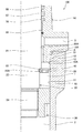
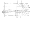
第1実施形態に係る油圧シリンダ100は、図1に示すように、筒状のシリンダチューブ10と、シリンダチューブ10に挿入されるピストンロッド20と、ピストンロッド20の先端に連結されシリンダチューブ10の内周面に沿って摺動するピストン30と、ピストンロッド20の外周に設けられるクッション部40と、を備える。
次に、図13から図17を参照して本発明の第2実施形態に係る油圧シリンダ200について説明する。以下では、上記第1実施形態と異なる点を中心に説明し、上記第1実施形態の油圧シリンダ100と同一の構成には同一の符号を付して説明を省略する。
次に、図18から図21を参照して本発明の第3実施形態に係る油圧シリンダ300について説明する。以下では、上記第1実施形態と異なる点を中心に説明し、上記第1実施形態の油圧シリンダ100と同一の構成には同一の符号を付して説明を省略する。
Claims (10)
- シリンダチューブと、
前記シリンダチューブに挿入されるピストンロッドと、
前記ピストンロッドの先端に連結され前記シリンダチューブ内をロッド側室とボトム側室とに区画するピストンと、
前記ピストンロッドの外周に設けられ伸長作動時のストローク端付近で前記ピストンロッドを減速させるクッション部と、
前記ロッド側室に連通し前記ロッド側室に給排される作動流体が通過する給排通路と、
前記シリンダチューブに設けられ伸長作動時のストローク端付近で前記クッション部が当接する当接部と、を備え、
前記クッション部は、伸長作動時のストローク端付近で前記当接部に当接するクッションリングと、前記ピストンロッドの外周面に形成される凹部に収容された状態で前記ピストンロッドに対する前記クッションリングの相対移動を規制する規制部と、を有し、
伸長作動時のストローク端付近で前記クッションリングと前記当接部とが当接するのに伴い、前記給排通路と前記ロッド側室との直接の連通が前記クッションリングによって遮断されると共に前記規制部が前記凹部から脱出して前記ピストンロッドに対する前記クッションリングの相対移動が許容され、通過する作動流体に抵抗を付与するクッション通路を通じて前記ロッド側室の作動流体が前記給排通路から排出されることを特徴とする流体圧シリンダ。 - 前記規制部は、前記クッションリングの外周面と内周面とを挿通し径方向に移動自在に設けられる規制ピンであることを特徴とする請求項1に記載の流体圧シリンダ。
- 前記規制部は、それぞれ前記クッションリングの外周及び内周に設けられ拡縮可能に形成される一対の規制リングであることを特徴とする請求項1に記載の流体圧シリンダ。
- 前記規制部は、前記クッションリングに軸方向に隣接して設けられ合口隙間を有して拡縮可能に形成される拡縮リングであることを特徴とする請求項1に記載の流体圧シリンダ。
- 前記クッションリングは、前記拡縮リングに対向する端面の内側に形成される中央凹部を有し、
前記拡縮リングは、前記中央凹部に挿入される中央段部を有し、
前記拡縮リングが前記ピストンロッドの前記凹部に収容された状態では、前記中央凹部と前記中央段部との間には径方向隙間が形成され、
前記拡縮リングが拡張して前記凹部から脱出した状態では、前記中央段部が前記中央凹部に接触することを特徴とする請求項4に記載の流体圧シリンダ。 - 前記シリンダチューブの内周面は、前記ピストンが摺動する摺動面と、前記摺動面よりも大きな内径に形成される大径面と、を有し、
前記規制部は、前記摺動面との当接によって前記凹部からの脱出が規制され、前記大径面に対向することにより前記凹部からの脱出が許容されることを特徴とする請求項1、2、4、及び5のいずれか一つに記載の流体圧シリンダ。 - 前記シリンダチューブの内周面は、前記摺動面と前記大径面との間に形成される内周段差部をさらに有し、
前記規制部または前記内周段差部の少なくとも一方には、前記クッションリングと前記当接部とが当接する状態からの前記ピストンロッドの収縮方向への移動に伴い、前記規制部を径方向内側に押し出して前記凹部に収容させる収容案内部が形成されることを特徴とする請求項6に記載の流体圧シリンダ。 - 前記クッションリングと前記当接部とが当接した状態において、前記規制部と前記内周段差部との間には、軸方向の隙間が形成されることを特徴とする請求項7に記載の流体圧シリンダ。
- 前記規制部または前記凹部の少なくとも一方には、前記クッションリングと前記当接部とが当接する状態からの前記ピストンロッドの伸長方向への移動に伴い、前記規制部を径方向外側に押し出して前記凹部から脱出させる脱出案内部が形成されることを特徴とする請求項1から8のいずれか一つに記載の流体圧シリンダ。
- 前記クッション通路は、前記クッションリングに着脱可能に設けられるオリフィスプラグに形成されることを特徴とする請求項1から9のいずれか一つに記載の流体圧シリンダ。
Priority Applications (4)
| Application Number | Priority Date | Filing Date | Title |
|---|---|---|---|
| JP2016072428A JP6255440B2 (ja) | 2016-03-31 | 2016-03-31 | 流体圧シリンダ |
| DE112017001603.7T DE112017001603T5 (de) | 2016-03-31 | 2017-03-27 | Fluiddruckzylinder |
| CN201780019665.9A CN108779789B (zh) | 2016-03-31 | 2017-03-27 | 流体压缸 |
| PCT/JP2017/012323 WO2017170361A1 (ja) | 2016-03-31 | 2017-03-27 | 流体圧シリンダ |
Applications Claiming Priority (1)
| Application Number | Priority Date | Filing Date | Title |
|---|---|---|---|
| JP2016072428A JP6255440B2 (ja) | 2016-03-31 | 2016-03-31 | 流体圧シリンダ |
Publications (3)
| Publication Number | Publication Date |
|---|---|
| JP2017180780A JP2017180780A (ja) | 2017-10-05 |
| JP2017180780A5 JP2017180780A5 (ja) | 2017-11-16 |
| JP6255440B2 true JP6255440B2 (ja) | 2017-12-27 |
Family
ID=59965588
Family Applications (1)
| Application Number | Title | Priority Date | Filing Date |
|---|---|---|---|
| JP2016072428A Active JP6255440B2 (ja) | 2016-03-31 | 2016-03-31 | 流体圧シリンダ |
Country Status (4)
| Country | Link |
|---|---|
| JP (1) | JP6255440B2 (ja) |
| CN (1) | CN108779789B (ja) |
| DE (1) | DE112017001603T5 (ja) |
| WO (1) | WO2017170361A1 (ja) |
Families Citing this family (1)
| Publication number | Priority date | Publication date | Assignee | Title |
|---|---|---|---|---|
| JP7323103B2 (ja) * | 2020-07-22 | 2023-08-08 | Smc株式会社 | 流体圧シリンダ |
Family Cites Families (11)
| Publication number | Priority date | Publication date | Assignee | Title |
|---|---|---|---|---|
| US4009639A (en) * | 1973-08-09 | 1977-03-01 | Kayabakogyo-Kabushiki-Kaisha | Hydraulic swing motor |
| JPS60125404A (ja) * | 1983-12-12 | 1985-07-04 | Kayaba Ind Co Ltd | シリンダのクツシヨン装置 |
| KR100386185B1 (ko) * | 1998-05-29 | 2003-06-02 | 히다치 겡키 가부시키 가이샤 | 유압 실린더 |
| KR20040072846A (ko) * | 2003-02-11 | 2004-08-19 | 현대모비스 주식회사 | 댐퍼 |
| CN101761520A (zh) * | 2010-02-06 | 2010-06-30 | 楼天汝 | 减压缓冲油缸 |
| JP5730058B2 (ja) | 2011-02-17 | 2015-06-03 | Kyb−Ys株式会社 | 流体圧シリンダ |
| JP5789456B2 (ja) * | 2011-09-06 | 2015-10-07 | カヤバ工業株式会社 | 流体圧シリンダ |
| US10151333B2 (en) * | 2013-02-13 | 2018-12-11 | Safran Landing Systems Canada Inc./ Safran Systèmes d'Atterrissage Canada Inc. | Modular actuator with snubbing arrangement |
| CN203743126U (zh) * | 2013-12-30 | 2014-07-30 | 中船重工中南装备有限责任公司 | 一种双浮动缓冲液压缸 |
| JP2016072428A (ja) | 2014-09-30 | 2016-05-09 | 株式会社ディスコ | ウエーハの保持方法 |
| CN105090159A (zh) * | 2015-08-29 | 2015-11-25 | 济南大学 | 一种基于颤振机理的低摩擦快启液压缸 |
-
2016
- 2016-03-31 JP JP2016072428A patent/JP6255440B2/ja active Active
-
2017
- 2017-03-27 CN CN201780019665.9A patent/CN108779789B/zh active Active
- 2017-03-27 DE DE112017001603.7T patent/DE112017001603T5/de active Pending
- 2017-03-27 WO PCT/JP2017/012323 patent/WO2017170361A1/ja active Application Filing
Also Published As
| Publication number | Publication date |
|---|---|
| CN108779789B (zh) | 2020-07-14 |
| JP2017180780A (ja) | 2017-10-05 |
| WO2017170361A1 (ja) | 2017-10-05 |
| DE112017001603T5 (de) | 2018-12-13 |
| CN108779789A (zh) | 2018-11-09 |
Similar Documents
| Publication | Publication Date | Title |
|---|---|---|
| WO2011099402A1 (ja) | 流体圧シリンダ | |
| US10655702B2 (en) | Controllable vibration damper for motor vehicles | |
| KR20180014164A (ko) | 일체형 체크-릴리프 밸브 | |
| KR102456303B1 (ko) | 조정 가능한 스프링 지지대 | |
| KR20180081514A (ko) | 압력 매체 라인을 연결하기 위한 커플링용 커플링 요소 | |
| US7712482B2 (en) | Pressure-reducing valve | |
| JP6255440B2 (ja) | 流体圧シリンダ | |
| KR101596176B1 (ko) | 유체압 실린더 | |
| JP6275459B2 (ja) | 流体圧シリンダ | |
| KR101910227B1 (ko) | 유체압 실린더 | |
| KR20180069028A (ko) | 유체압 기기 및 그 제조방법 | |
| KR20150065711A (ko) | 유체압 실린더 | |
| US6796216B2 (en) | Guide for the piston rod of a piston-cylinder assembly | |
| JP5767990B2 (ja) | 流体圧シリンダ | |
| US10451093B2 (en) | Fluid pressure cylinder | |
| JP2019035459A (ja) | スプール弁 | |
| JP2006146776A (ja) | 減圧弁 | |
| JP2005220926A (ja) | オイルロック構造 | |
| KR20170116024A (ko) | 유체압 실린더 | |
| KR20180006895A (ko) | 액압 실린더 | |
| JP2018112232A (ja) | 油圧緩衝器用密封装置 | |
| KR20130137221A (ko) | 유체압 실린더의 쿠션 기구 | |
| JP2019199955A (ja) | 流体圧シリンダ | |
| JP2019199954A (ja) | 流体圧シリンダ | |
| JP2023074663A (ja) | シリンダ装置 |
Legal Events
| Date | Code | Title | Description |
|---|---|---|---|
| A521 | Request for written amendment filed |
Free format text: JAPANESE INTERMEDIATE CODE: A523 Effective date: 20170823 |
|
| A621 | Written request for application examination |
Free format text: JAPANESE INTERMEDIATE CODE: A621 Effective date: 20170823 |
|
| A871 | Explanation of circumstances concerning accelerated examination |
Free format text: JAPANESE INTERMEDIATE CODE: A871 Effective date: 20170823 |
|
| A975 | Report on accelerated examination |
Free format text: JAPANESE INTERMEDIATE CODE: A971005 Effective date: 20170829 |
|
| A131 | Notification of reasons for refusal |
Free format text: JAPANESE INTERMEDIATE CODE: A131 Effective date: 20170905 |
|
| A521 | Request for written amendment filed |
Free format text: JAPANESE INTERMEDIATE CODE: A523 Effective date: 20171012 |
|
| TRDD | Decision of grant or rejection written | ||
| A01 | Written decision to grant a patent or to grant a registration (utility model) |
Free format text: JAPANESE INTERMEDIATE CODE: A01 Effective date: 20171107 |
|
| A61 | First payment of annual fees (during grant procedure) |
Free format text: JAPANESE INTERMEDIATE CODE: A61 Effective date: 20171204 |
|
| R151 | Written notification of patent or utility model registration |
Ref document number: 6255440 Country of ref document: JP Free format text: JAPANESE INTERMEDIATE CODE: R151 |
|
| R250 | Receipt of annual fees |
Free format text: JAPANESE INTERMEDIATE CODE: R250 |
|
| S533 | Written request for registration of change of name |
Free format text: JAPANESE INTERMEDIATE CODE: R313533 |
|
| R350 | Written notification of registration of transfer |
Free format text: JAPANESE INTERMEDIATE CODE: R350 |