JP6231337B2 - Automotive heat exchanger apparatus and air conditioning system - Google Patents
Automotive heat exchanger apparatus and air conditioning system Download PDFInfo
- Publication number
- JP6231337B2 JP6231337B2 JP2013195620A JP2013195620A JP6231337B2 JP 6231337 B2 JP6231337 B2 JP 6231337B2 JP 2013195620 A JP2013195620 A JP 2013195620A JP 2013195620 A JP2013195620 A JP 2013195620A JP 6231337 B2 JP6231337 B2 JP 6231337B2
- Authority
- JP
- Japan
- Prior art keywords
- air
- heat exchanger
- flow
- condenser
- refrigerant
- Prior art date
- Legal status (The legal status is an assumption and is not a legal conclusion. Google has not performed a legal analysis and makes no representation as to the accuracy of the status listed.)
- Active
Links
Images


Classifications
-
- B—PERFORMING OPERATIONS; TRANSPORTING
- B60—VEHICLES IN GENERAL
- B60H—ARRANGEMENTS OF HEATING, COOLING, VENTILATING OR OTHER AIR-TREATING DEVICES SPECIALLY ADAPTED FOR PASSENGER OR GOODS SPACES OF VEHICLES
- B60H1/00—Heating, cooling or ventilating [HVAC] devices
- B60H1/00321—Heat exchangers for air-conditioning devices
- B60H1/00328—Heat exchangers for air-conditioning devices of the liquid-air type
-
- B—PERFORMING OPERATIONS; TRANSPORTING
- B60—VEHICLES IN GENERAL
- B60H—ARRANGEMENTS OF HEATING, COOLING, VENTILATING OR OTHER AIR-TREATING DEVICES SPECIALLY ADAPTED FOR PASSENGER OR GOODS SPACES OF VEHICLES
- B60H1/00—Heating, cooling or ventilating [HVAC] devices
- B60H1/00007—Combined heating, ventilating, or cooling devices
- B60H1/00021—Air flow details of HVAC devices
- B60H1/00028—Constructional lay-out of the devices in the vehicle
-
- B—PERFORMING OPERATIONS; TRANSPORTING
- B60—VEHICLES IN GENERAL
- B60H—ARRANGEMENTS OF HEATING, COOLING, VENTILATING OR OTHER AIR-TREATING DEVICES SPECIALLY ADAPTED FOR PASSENGER OR GOODS SPACES OF VEHICLES
- B60H1/00—Heating, cooling or ventilating [HVAC] devices
- B60H1/00007—Combined heating, ventilating, or cooling devices
- B60H1/00021—Air flow details of HVAC devices
- B60H1/00035—Air flow details of HVAC devices for sending an air stream of uniform temperature into the passenger compartment
- B60H1/00057—Air flow details of HVAC devices for sending an air stream of uniform temperature into the passenger compartment the air being heated and cooled simultaneously, e.g. using parallel heat exchangers
-
- B—PERFORMING OPERATIONS; TRANSPORTING
- B60—VEHICLES IN GENERAL
- B60H—ARRANGEMENTS OF HEATING, COOLING, VENTILATING OR OTHER AIR-TREATING DEVICES SPECIALLY ADAPTED FOR PASSENGER OR GOODS SPACES OF VEHICLES
- B60H1/00—Heating, cooling or ventilating [HVAC] devices
- B60H1/00007—Combined heating, ventilating, or cooling devices
- B60H1/00021—Air flow details of HVAC devices
- B60H1/00064—Air flow details of HVAC devices for sending air streams of different temperatures into the passenger compartment
-
- B—PERFORMING OPERATIONS; TRANSPORTING
- B60—VEHICLES IN GENERAL
- B60H—ARRANGEMENTS OF HEATING, COOLING, VENTILATING OR OTHER AIR-TREATING DEVICES SPECIALLY ADAPTED FOR PASSENGER OR GOODS SPACES OF VEHICLES
- B60H1/00—Heating, cooling or ventilating [HVAC] devices
- B60H1/00007—Combined heating, ventilating, or cooling devices
- B60H1/00021—Air flow details of HVAC devices
- B60H2001/00078—Assembling, manufacturing or layout details
- B60H2001/00085—Assembling, manufacturing or layout details of air intake
-
- B—PERFORMING OPERATIONS; TRANSPORTING
- B60—VEHICLES IN GENERAL
- B60H—ARRANGEMENTS OF HEATING, COOLING, VENTILATING OR OTHER AIR-TREATING DEVICES SPECIALLY ADAPTED FOR PASSENGER OR GOODS SPACES OF VEHICLES
- B60H1/00—Heating, cooling or ventilating [HVAC] devices
- B60H1/00007—Combined heating, ventilating, or cooling devices
- B60H1/00021—Air flow details of HVAC devices
- B60H2001/00114—Heating or cooling details
- B60H2001/00135—Deviding walls for separate air flows
-
- B—PERFORMING OPERATIONS; TRANSPORTING
- B60—VEHICLES IN GENERAL
- B60H—ARRANGEMENTS OF HEATING, COOLING, VENTILATING OR OTHER AIR-TREATING DEVICES SPECIALLY ADAPTED FOR PASSENGER OR GOODS SPACES OF VEHICLES
- B60H1/00—Heating, cooling or ventilating [HVAC] devices
- B60H1/00007—Combined heating, ventilating, or cooling devices
- B60H1/00021—Air flow details of HVAC devices
- B60H2001/0015—Temperature regulation
- B60H2001/00178—Temperature regulation comprising an air passage from the HVAC box to the exterior of the cabin
Landscapes
- Physics & Mathematics (AREA)
- Thermal Sciences (AREA)
- Engineering & Computer Science (AREA)
- Mechanical Engineering (AREA)
- Air-Conditioning For Vehicles (AREA)
- Heat-Exchange Devices With Radiators And Conduit Assemblies (AREA)
Description
本発明は、冷媒回路に組み込まれ、冷媒及び空気が供給可能である熱交換器を備える、空気を暖める熱交換器装置に関する。熱は、冷媒から空気へ伝達される。
また、本発明は、熱交換器装置を備えた、自動車の客室の空気を調和する空調システムに関する。空調システムは、空気を誘導するための第1フローチャネルと第2フローチャネルとを備えたハウジング、並びに第1熱交換器と、圧縮機と、熱交換器装置の熱交換器に相当する第2熱交換器と、膨張素子とを備えた冷媒回路を有し、第1熱交換器は第1フローチャネルに配置され、第2熱交換器は第2フローチャネルに配置されている。
さらに、本発明は、冷却設備運転及び加熱運転、並びに再熱運転で客室の空気を調和する再熱運転のために空調システムを作動させる方法に関する。
The present invention relates to a heat exchanger device for warming air, which includes a heat exchanger incorporated in a refrigerant circuit and capable of supplying refrigerant and air. Heat is transferred from the refrigerant to the air.
The present invention also relates to an air conditioning system that includes a heat exchanger device and that harmonizes the air in the passenger compartment of an automobile. The air conditioning system includes a housing having a first flow channel and a second flow channel for guiding air, a first heat exchanger, a compressor, and a second heat exchanger corresponding to a heat exchanger of the heat exchanger device. The refrigerant circuit includes a heat exchanger and an expansion element, the first heat exchanger is disposed in the first flow channel, and the second heat exchanger is disposed in the second flow channel.
Furthermore, the present invention relates to a method for operating an air conditioning system for cooling equipment operation and heating operation, and for reheating operation to reconcile cabin air in reheating operation.
以前から従来技術に属する自動車の空調設備は、慣習的に車両の正面に配置される凝縮器、車両エンジンに接続され車両エンジンによって駆動される圧縮機、客室に配置された蒸発器、及びパイプやコネクタなどの種々異なる個別構成部品を有する冷媒回路を備えている。空調設備が空気を調和し、続いて、空気が客室に導入される。圧縮機は、通例、自動車のエンジンによって、機械的エネルギーを圧縮機シャフトへ入力することにより駆動される。冷却装置送風器とファンとは12Vの車載電源系統から給電される。 Conventionally, the air conditioning equipment of an automobile belonging to the prior art has been conventionally used in a condenser placed in front of the vehicle, a compressor connected to the vehicle engine and driven by the vehicle engine, an evaporator arranged in the passenger cabin, a pipe, A refrigerant circuit having various individual components such as a connector is provided. Air conditioning equipment harmonizes the air, and then air is introduced into the cabin. The compressor is typically driven by an automobile engine by inputting mechanical energy into the compressor shaft. The cooling device blower and the fan are supplied with power from a 12V on-vehicle power supply system.
圧縮機で圧縮された気体の冷媒から、コンデンサにおいて高圧力レベルで熱が取り去られる。未臨界の運転では、過熱された冷媒が凝縮温度にまで冷却され、続いて、一定の温度で液化される。その後、完全に液化された冷媒が凝縮器で引き続き冷却される。冷媒は過冷却され、その場合、過冷却は一定の凝縮温度に関連付けられる。冷媒が過冷却される凝縮器の領域は過冷却領域とも呼ばれる。冷媒は、凝縮器の出口において、通常、凝縮温度よりも約5K〜10K低い温度を有する。 Heat is removed from the gaseous refrigerant compressed by the compressor at a high pressure level in the condenser. In subcritical operation, the superheated refrigerant is cooled to the condensation temperature and then liquefied at a constant temperature. Thereafter, the completely liquefied refrigerant is subsequently cooled in the condenser. The refrigerant is supercooled, in which case the supercooling is associated with a constant condensation temperature. The region of the condenser where the refrigerant is supercooled is also called the supercooling region. The refrigerant typically has a temperature about 5K to 10K below the condensation temperature at the outlet of the condenser.
自動車の正面領域における取付け位置で、凝縮器は、空気の流れ方向に対して垂直に設けられ、大抵の場合、大きい網面(Netzflaeche)を具備しており、小型の自動車では14dm2〜18dm2の範囲の値であり、コンパクトクラスの自動車では20dm2〜22dm2の範囲の値であり、比較的大きい自動車では24dm2よりも大きい値である。
網面とは、熱交換器の入口若しくは出口における空気の流れ方向に対して実質的に垂直に向けられた面と解され、流面とも呼ばれる。その場合、網面は、熱交換器のリブ付き、若しくはリブが形成された領域を備え、且つ空気側の流断面に相当する。
In the mounting position in the front region of the motor vehicle, the condenser is provided perpendicular to the flow direction of air, in most cases, are provided with a large mesh surface (Netzflaeche), 14dm 2 ~18dm 2 is a small car The value is in the range of 20
The mesh surface is understood as a surface oriented substantially perpendicular to the air flow direction at the inlet or outlet of the heat exchanger, and is also called a flow surface. In that case, the mesh surface is provided with a rib of the heat exchanger or a region where the rib is formed, and corresponds to a flow section on the air side.
凝縮器の、冷却装置送風器とも呼ばれる従来のファンは、軸流ファンとして設計されており、吸引送風器として冷却モジュールの出口に配置されている。軸流送風器は圧力差が小さい場合に大きい空気体積流を送るように設計されているので、エンジン冷却回路の冷却剤冷却装置、給気冷却装置、又は冷媒回路の凝縮器などの冷却モジュールに配置された熱交換器は、流体抵抗を低減するために、奥行きを可能な限り小さくして形成される。熱交換器には、空気側で連続的に貫流される。
その場合、奥行きとは、空気の流れ方向の熱交換器の厚さ、若しくは空気側の流長さと解される。従来技術から公知の凝縮器の奥行の値は、12mm〜16mmの範囲である。空気側の流長さが小さく空気量が多いことに基づいて、空気質量流は、凝縮器を貫流する際に、その全体がほんの少しだけ暖められる。その場合、圧縮機の冷媒側入口領域の空気質量流は、凝縮温度よりも高い温度の冷媒の加熱に基づいて、冷媒がすでに凝縮されて場合によっては過冷却された状態になる凝縮器の冷媒側出口領域よりもはるかに強く暖められる。
A conventional fan of the condenser, also called a cooling device blower, is designed as an axial fan and is arranged at the outlet of the cooling module as a suction blower. Axial fans are designed to deliver a large volume of air flow when the pressure differential is small, so they can be used in cooling modules such as coolant cooling devices in engine cooling circuits, supply air cooling devices, or condensers in refrigerant circuits. The arranged heat exchanger is formed with the smallest possible depth in order to reduce the fluid resistance. The heat exchanger is continuously flown on the air side.
In this case, the depth is understood as the thickness of the heat exchanger in the air flow direction or the flow length on the air side. The condenser depth values known from the prior art are in the range of 12 mm to 16 mm. On the basis of the small flow length on the air side and the large amount of air, the air mass flow is warmed only slightly as it flows through the condenser. In that case, the air mass flow in the refrigerant-side inlet region of the compressor is based on the heating of the refrigerant at a temperature higher than the condensing temperature, and the refrigerant in the condenser that is already condensed due to the refrigerant being already condensed. Warm much stronger than the side exit area.
車両駆動装置の効率的な内燃機関の冷却剤回路から熱出力を引き出す冷却剤・空気熱交換器を備えた同種の空調設備は、例えば−10℃未満の低い周囲温度では、車室の快適な加熱のために必要な温度レベルに達しなくなる。ハイブリッド駆動装置を有する車両における設備についても同じことが言える。この車両には、補助加熱設計の使用が必要である。
グリコール・空気ヒートポンプも内燃機関の冷却剤を利用するが、それは熱源としてである。その場合、熱は、冷却剤から取り出される。その結果、内燃機関は、低温でより長時間運転され、このことが排ガスの排出及び燃費に悪影響を及ぼす。ハイブリッド車では内燃機関を間欠的に作動させるので、作動時間が比較的長い場合でも冷却剤が十分に高い温度に達しない。その結果として、周囲温度が低いと内燃機関の始動・停止運転が中断される。内燃機関はスイッチオフされない。
A similar type of air conditioning system with a coolant / air heat exchanger that draws heat output from the coolant circuit of an efficient internal combustion engine of the vehicle drive system is comfortable in the passenger compartment, for example, at low ambient temperatures below -10 ° C. The temperature level required for heating is not reached. The same is true for equipment in a vehicle having a hybrid drive. This vehicle requires the use of an auxiliary heating design.
Glycol air heat pumps also use coolant for internal combustion engines, but as a heat source. In that case, heat is removed from the coolant. As a result, the internal combustion engine is operated at a lower temperature for a longer time, which adversely affects exhaust gas emissions and fuel consumption. In the hybrid vehicle, the internal combustion engine is intermittently operated, so that the coolant does not reach a sufficiently high temperature even when the operation time is relatively long. As a result, when the ambient temperature is low, the start / stop operation of the internal combustion engine is interrupted. The internal combustion engine is not switched off.
さらに、例えば、バッテリ又は燃料電池で駆動される車両などのように、駆動装置が完全に電化される傾向がある。その場合、空気を暖めるために考えられる熱源として内燃機関の廃熱を用いることはできなくなる。さらに、自動車のバッテリに蓄積可能なエネルギー量は、燃料タンク内に液体燃料の形態で貯蔵可能なエネルギー量よりも少ない。従って、電気的に駆動される自動車の客室の空気を調和するために必要な出力は、自動車の走行距離に相当な影響を及ぼす。 Furthermore, the drive device tends to be completely electrified, such as a vehicle driven by a battery or a fuel cell. In that case, the waste heat of the internal combustion engine cannot be used as a possible heat source for warming the air. Furthermore, the amount of energy that can be stored in the vehicle battery is less than the amount of energy that can be stored in the form of liquid fuel in the fuel tank. Therefore, the output required to harmonize the air in the passenger compartment of an electrically driven automobile has a considerable effect on the mileage of the automobile.
特許文献1(独国特許出願公開第102009028522号明細書)において、蒸発器ユニットと、凝縮器ユニットと、構成部品ユニット、並びに冷媒回路を備えた小型空調設備が記載されている。蒸発器ユニットと凝縮器ユニットとは、それぞれ、ハウジング内に配置された空気流熱交換器とファンとを有する。蒸発器と凝縮器と再熱器とを備えた冷媒回路は、冷却設備運転とヒートポンプ運転との組合せ、並びに再熱運転のために形成されており、再熱運転において、凝縮器/ガス冷却器として形成された再熱器の熱出力と蒸発器の冷却出力とは、互いに独立して制御可能である。空調設備の運転モードは、冷媒回路により操作される。従って、空調設備は、1つの1次回路と、2つの流路から形成された2次系統とを有する冷媒回路の範囲内で能動的に切り替えることによって実現されるヒートポンプの機能を果たす。しかしながら、切替弁を有する冷媒回路の形成によって複雑度が増し、このこともまたコスト上昇と技術的手間の増加を引き起こす。 In Patent Document 1 (German Patent Application Publication No. 102009028522), a small air conditioning system including an evaporator unit, a condenser unit, a component unit, and a refrigerant circuit is described. The evaporator unit and the condenser unit each have an air flow heat exchanger and a fan disposed in the housing. A refrigerant circuit comprising an evaporator, a condenser, and a reheater is formed for a combination of a cooling facility operation and a heat pump operation, and a reheat operation. In the reheat operation, a condenser / gas cooler is formed. The heat output of the reheater formed as and the cooling output of the evaporator can be controlled independently of each other. The operation mode of the air conditioning equipment is operated by the refrigerant circuit. Therefore, the air conditioner functions as a heat pump realized by actively switching within the range of the refrigerant circuit having one primary circuit and a secondary system formed by two flow paths. However, the formation of a refrigerant circuit having a switching valve increases the complexity, which also causes an increase in cost and technical effort.
特許文献2(仏国特許出願公開第2743027号明細書)から、蒸発器と圧縮機と凝縮器と膨張素子とを有しているだけの従来の冷媒回路を備えた車両空調設備が読みとれる。熱交換器は、少なくとも流体技術的に互いに分離して形成された別々のフローチャネルに配置されている。フローチャネルは、交差接続又はバイパスを有する。ファンによって吸入された空気質量流は、フラップを閉鎖及び開放することによって、且つ必要及び動作モードに応じて、バイパスを通じて誘導されることによって熱交換器の表面に導かれる。その場合、空気質量流は冷却及び/又は除湿、若しくは加熱され、続いて、客室及び/又は周囲へ導出される。 From Patent Document 2 (French Patent Application Publication No. 2743027), a vehicle air conditioner equipped with a conventional refrigerant circuit only having an evaporator, a compressor, a condenser, and an expansion element can be read. The heat exchangers are arranged in separate flow channels which are formed at least fluidically separate from each other. The flow channel has a cross-connection or bypass. The air mass flow drawn by the fan is directed to the surface of the heat exchanger by closing and opening the flap and, if necessary and depending on the mode of operation, being guided through the bypass. In that case, the air mass flow is cooled and / or dehumidified or heated and subsequently led to the cabin and / or the surroundings.
従って、従来技術から、客室に給送されるべき、且つ調和されるべき空気を加熱、冷却、及び除湿するための熱源として空気を用いる冷却設備運転とヒートポンプ運転との組合せのための、自動車の空調設備が公知である。これらの空調設備は、冷媒回路側又は空気側で操作される。 Thus, from the prior art, a motor vehicle for a combination of cooling facility operation and heat pump operation using air as a heat source for heating, cooling and dehumidifying the air to be delivered to the cabin and conditioned. Air conditioning equipment is known. These air conditioning facilities are operated on the refrigerant circuit side or the air side.
しかしながら、空気側で操作される空調設備によってでは、リヒートとも呼ばれる再熱モードでの運転が可能でない。付加的再熱運転のために形成された空調設備もまた、熱交換器、切替弁、及び膨張弁などの複数の構成部品を備えた複雑な冷媒回路を有する。
「リヒート」若しくは再熱運転において、客室に給送された空気が冷却され、その際に除湿され、続いて、除湿された空気がわずかに加熱される。この運転モードにおいて、必要な再熱出力は、大抵の場合、空気を冷却及び除湿するために必要な冷却出力よりも小さい。
However, with an air conditioning facility operated on the air side, operation in a reheat mode, also called reheat, is not possible. An air conditioner configured for additional reheat operation also has a complex refrigerant circuit with multiple components such as a heat exchanger, a switching valve, and an expansion valve.
In “reheat” or reheat operation, the air delivered to the cabin is cooled and dehumidified, followed by slight heating of the dehumidified air. In this mode of operation, the reheat output required is often less than the cooling output required to cool and dehumidify the air.
公知のヒートポンプ機能を有する空気側で操作される空調設備では、冷却設備運転でもヒートポンプ運転でも蒸発器を蒸発器として、凝縮器を凝縮器として作動させる。その場合、熱流の操作は、すべて空気側の流れガイドを介して実現される。熱交換器を凝縮器としての作動と、蒸発器としての作動とに切り替える必要はない。 In an air conditioner operated on the air side having a known heat pump function, the evaporator is operated as an evaporator and the condenser is operated as a condenser in both cooling equipment operation and heat pump operation. In that case, all the heat flow manipulation is realized via the air-side flow guide. There is no need to switch the heat exchanger between operation as a condenser and operation as an evaporator.
しかし、ヒートポンプ運転用に設計された凝縮器の伝達性能は、冷却設備運転用に設計された凝縮器の伝達性能よりも低い。ヒートポンプ運転用の凝縮器には比較的小さい空気質量流が貫流し、空気の温度の比較的大きい変化を生ぜしめなければならない。
従来技術によれば、ヒートポンプシステムにおいて、エンジン冷却回路の冷却剤が貫流する熱交換器の取付けスペースを有する凝縮器が用いられる。この理由から、凝縮器は約40mmの構造奥行、及び約4dm2の流面を有する多列式、例えば2列の交差向流熱交換器として形成されている。約40mmの構造奥行と約4dm2の流面とを有する凝縮器は、2列式交差向流熱交換器としての運転時に250kg/h〜400kg/hの範囲の空気質量流を、冷媒の凝縮温度よりも低い約5K〜15Kの温度に暖めることができる。
However, the transmission performance of a condenser designed for heat pump operation is lower than that of a condenser designed for cooling facility operation. A relatively small air mass flow must flow through the condenser for heat pump operation and cause a relatively large change in the temperature of the air.
According to the prior art, in a heat pump system, a condenser having a space for mounting a heat exchanger through which coolant of an engine cooling circuit flows is used. For this reason, the condenser is formed as a multi-row, for example two-row cross-counter heat exchanger with a structural depth of about 40 mm and a flow surface of about 4 dm 2 . A condenser having a structural depth of about 40 mm and a flow surface of about 4 dm 2 produces an air mass flow in the range of 250 kg / h to 400 kg / h during operation as a two-row cross-counter heat exchanger, condensing refrigerant. It can be warmed to a temperature of about 5K-15K, which is lower than the temperature.
熱交換器を、冷却設備運転及びヒートポンプ運転で凝縮器として作動させる場合、自動車の冷却モジュールに凝縮器を配置することは賢明ではない。
従来技術において公知の、冷却設備運転用の凝縮器の構造が大きいために、すなわち、空気側の流断面が大きいために、自動車において冷却モジュール以外の他の領域に配置することはほとんど不可能である。
その一方で、ヒートポンプ運転用に設計された凝縮器の構造では、冷却設備運転のために必要な出力が伝達不可能である。それに加えて、空気質量流は、冷媒の凝縮温度に加熱できず、まして冷媒の凝縮温度よりも高い温度に加熱することなどできない。
When the heat exchanger is operated as a condenser in cooling facility operation and heat pump operation, it is not wise to place the condenser in the automotive cooling module.
Due to the large structure of the condenser for cooling equipment operation known in the prior art, that is, the flow section on the air side is large, it is almost impossible to arrange it in other areas than the cooling module in the automobile. is there.
On the other hand, the condenser structure designed for heat pump operation cannot transmit the output required for cooling facility operation. In addition, the air mass flow cannot be heated to the refrigerant condensing temperature, nor can it be heated to a temperature higher than the refrigerant condensing temperature.
本発明の課題は、空気を暖めるための熱交換器装置を提供することであり、その場合、空気は、熱交換器を通って流れる冷媒によって暖められるべきである。その場合、空気は、効率的に最高温度に暖めることができるべきである。
本発明のさらに別の課題は、加熱機能を有する、特に自動車において使用するための空調システムを提供することである。空調システムの冷媒回路は、最小限の数の構成部品のみで形成され、従って低コストで、且つ保守の手間がかからないものでなければならない。それに加えて、空調システムは、調和されるべき客室の空気を加熱、冷却、及び除湿する、冷却設備運転とヒートポンプ運転との組合せ、及び再熱運転のために形成されていなければならない。その場合、例えば、エネルギー効率のよい内燃機関、又は内燃機関と電気モータとからなるハイブリッド駆動装置の場合など容量の熱源を有する周囲環境、又は、例えば、電気的に駆動される自動車の場合など、駆動装置からの熱源が無い場合にも、客室における快適な空調のすべての要求を満たす運転が可能であるべきである。空調システムは、空気に熱を放出するための熱交換器装置を用いて非常に効率的に作動可能であるべきである。本発明は、さらに、特に再熱運転において効率的な運転を可能にする空調ステムを作動させる方法を提供することに基づく。
The object of the present invention is to provide a heat exchanger device for warming the air, in which case the air should be warmed by the refrigerant flowing through the heat exchanger. In that case, the air should be able to efficiently warm to the maximum temperature.
Yet another object of the present invention is to provide an air conditioning system having a heating function, particularly for use in an automobile. The refrigerant circuit of an air conditioning system must be formed with only a minimum number of components, and therefore must be low cost and maintenance free. In addition, the air conditioning system must be configured for a combination of refrigeration and heat pump operation, and reheat operation that heats, cools, and dehumidifies the cabin air to be conditioned. In that case, for example, an ambient environment with a heat source of capacity, such as in the case of an energy efficient internal combustion engine, or a hybrid drive device comprising an internal combustion engine and an electric motor, or in the case of an electrically driven vehicle, for example, Even in the absence of a heat source from the drive, it should be possible to operate to meet all the requirements of comfortable air conditioning in the cabin. The air conditioning system should be able to operate very efficiently with a heat exchanger device for releasing heat into the air. The present invention is further based on providing a method for operating an air conditioning system that enables efficient operation, particularly in reheat operation.
上記課題は、本発明によると、冷媒回路に組み込んで配置された熱交換器を有する空気を暖めるための熱交換器装置によって解決される。熱交換器は、熱が冷媒から空気へ伝達可能であるように、冷媒が貫流可能である一方で、空気が供給可能に形成されている。冷媒は、熱放出時に抜熱、凝縮、及び過冷却される。 According to the present invention, the above problem is solved by a heat exchanger apparatus for warming air having a heat exchanger arranged in a refrigerant circuit. The heat exchanger is formed so that air can be supplied while the refrigerant can flow therethrough so that heat can be transferred from the refrigerant to the air. The refrigerant removes heat, condenses, and is supercooled when the heat is released.
本発明の概念によれば、熱交換器は互いに分離して形成された2つの構成部品を有する。第1構成部品は、凝縮面と抜熱面とを備えて形成され、第2構成部品は、過冷却面を備えて形成されている。凝縮器として作動される熱交換器の第1構成部品に冷媒が流入した後に、過熱された蒸気として、若しくはガスとして存在する冷媒が抜熱され、すなわち、凝縮温度に達するまで冷却される。熱を冷媒から空気質量流へ引き続き伝達することによって、冷媒が、一定の温度、凝縮温度で液化される。続いて、液化した冷媒は、熱交換器の第1構成部品から第2構成部品に誘導され、第2構成部品内で熱をさらに放出することによって凝縮温度よりも低い温度に冷却される。過冷却は、凝縮温度よりも低い第2構成部品の出口における温度に当てはまる。 According to the inventive concept, the heat exchanger has two components formed separately from each other. The first component is formed with a condensation surface and a heat removal surface, and the second component is formed with a supercooling surface. After the refrigerant has flowed into the first component of the heat exchanger operated as a condenser, the refrigerant present as superheated vapor or gas is removed, that is, cooled until the condensation temperature is reached. By continuing to transfer heat from the refrigerant to the air mass flow, the refrigerant is liquefied at a constant temperature and condensation temperature. Subsequently, the liquefied refrigerant is guided from the first component of the heat exchanger to the second component and is cooled to a temperature lower than the condensation temperature by further releasing heat in the second component. Subcooling applies to the temperature at the outlet of the second component that is below the condensing temperature.
熱交換器の互いに分離して形成された2つの構成部品間には、冷媒側に冷媒・相分離要素が配置されている。相分離によって、過冷却面を備えて形成されている第2構成部品には液体冷媒しか誘導されないことが確保される。全くの液相の冷媒は、有利にも、気体分を有する液体冷媒、若しくは2相冷媒よりも体積が小さい。
冷媒・相分離要素として、液体分離器が組み込まれたコレクタが使用されることが好ましい。
A refrigerant / phase separation element is disposed on the refrigerant side between two components formed separately from each other of the heat exchanger. The phase separation ensures that only the liquid refrigerant is induced in the second component formed with the supercooling surface. A completely liquid phase refrigerant advantageously has a smaller volume than a liquid refrigerant with a gas content or a two-phase refrigerant.
As the refrigerant / phase separation element, a collector incorporating a liquid separator is preferably used.
本発明では、熱交換器装置の熱交換器は、列で配置された管を有する管型熱交換器として形成されている。その場合、凝縮面及び抜熱面を有する第1構成部品は、少なくとも2列で形成される一方で、過冷却面を有する第2構成部品は、少なくとも1列で形成されている。 In the present invention, the heat exchanger of the heat exchanger apparatus is formed as a tubular heat exchanger having tubes arranged in rows. In that case, the first component having the condensation surface and the heat removal surface is formed in at least two rows, while the second component having the supercooling surface is formed in at least one row.
本発明の一実施形態では、第1構成部品は、少なくとも第2構成部品と同じ数の管列を有している。しかし、第1構成部品は、少なくとも第2構成部品の2倍の数の管列を備えて形成されていることが好ましい。その場合、第1構成部品は、4つの管列を備えて形成され、第2構成部品は2つの管列を有することが有利である。 In one embodiment of the invention, the first component has at least as many tube rows as the second component. However, the first component is preferably formed with at least twice as many tube rows as the second component. In that case, the first component is advantageously formed with four tube rows and the second component has two tube rows.
第1変形実施形態では、すべての管列がそれぞれ単流式である。その場合、管列は、空気の流れ方向に対して垂直に方向調整されていることが有利である。冷媒は、管列のすべての管を通って一方向に平行に流れ、次に、後続の管列の管を通じて誘導される。このようにして、異なった管列の管に冷媒側で連続的に貫流させる。その場合、1つの管列から後続の管列への冷媒の貫流は、空気側の流れ方向で行われてもよいし、これとは逆の方向で行われてもよい。
第2変形実施形態では、凝縮器として作動される熱交換器は、複数の管列の少なくとも1つの列が、複流式であるように形成される。その場合、冷媒は、1つの管列の幾つかの管を通って第1方向に誘導される一方で、同じ管列の別の管を通って第1方向とは逆の第2方向に流れる。その場合、冷媒は、管列の管を通ってそれぞれ平行に流れる。
In the first modified embodiment, all the tube rows are each a single flow type. In that case, the tube rows are advantageously oriented perpendicular to the direction of air flow. The refrigerant flows in parallel in one direction through all the tubes in the tube row and is then guided through the tubes in the subsequent tube row. In this way, the refrigerant is continuously passed through the pipes of different pipe rows. In that case, the flow of the refrigerant from one tube row to the subsequent tube row may be performed in the flow direction on the air side, or may be performed in the opposite direction.
In the second variant embodiment, the heat exchanger operated as a condenser is formed such that at least one of the plurality of tube rows is a double flow type. In that case, the refrigerant is guided in a first direction through several tubes of one tube row while flowing in a second direction opposite to the first direction through another tube of the same tube row. . In that case, the refrigerant flows in parallel through the tubes in the tube row.
本発明では、熱交換器装置の熱交換器を通って流れる空気質量流は、冷媒の凝縮温度レベルよりも高い温度レベルに加熱可能である。 In the present invention, the air mass flow flowing through the heat exchanger of the heat exchanger apparatus can be heated to a temperature level higher than the refrigerant condensation temperature level.
熱交換器は、交差向流熱交換器として形成されていることが有利である。 The heat exchanger is advantageously formed as a cross-counterflow heat exchanger.
本発明のさらなる改良の実施形態では、熱交換器の流面積は、2dm2〜10dm2の範囲であるが、好ましくは4dm2〜5dm2である。この流面積によって、熱交換器は、それぞれ必要な出力を伝達するために、自動車の空調システムの冷却設備運転とヒートポンプ運転の両方において凝縮器として使用可能である。
In a further refinement of the invention, the flow area of the heat exchanger is in the range of 2
熱交換器は、空気の流れ方向に対して垂直に形成されている扁平管から形成されていることが有利である。扁平管は、8mmよりも大きい幅を有している。その場合、扁平管の幅は、11.5mm〜18mmの範囲であることが好ましい。扁平管を12.3mm又は16mmの幅で形成することが有利である。扁平管の幅とは、空気の流れ方向の管の広がりと解される。 The heat exchanger is advantageously formed from a flat tube formed perpendicular to the air flow direction. The flat tube has a width greater than 8 mm. In that case, the width of the flat tube is preferably in the range of 11.5 mm to 18 mm. It is advantageous to form the flat tube with a width of 12.3 mm or 16 mm. The width of the flat tube is understood as the expansion of the tube in the air flow direction.
本発明の変形実施形態では、熱交換器は、空気の流れ方向に対して長手方向に所定角度傾斜させた扁平管から形成されている。有利な傾斜の値は、30°〜60°である。それによって、傾斜角度に応じて、扁平管の有効な広がり、若しくは管列の貫流時の空気質量流が流れる有効経路が拡大される In a modified embodiment of the present invention, the heat exchanger is formed from a flat tube inclined at a predetermined angle in the longitudinal direction with respect to the air flow direction. Advantageous tilt values are between 30 ° and 60 °. As a result, the effective path of the flat tube or the effective path through which the air mass flow flows through the tube row is expanded according to the inclination angle.
本発明のさらなる改良の実施形態では、熱交換器装置の熱交換器には、空気側にリブが形成されている。その場合、リブは、1dm当たり100個のリブよりも少ない密度で配置されていることが好ましい。リブは、1dm当たり65〜75個のリブの密度で配置することが有利である。 In a further improved embodiment of the invention, the heat exchanger of the heat exchanger device is provided with ribs on the air side. In that case, the ribs are preferably arranged at a density less than 100 ribs per dm. The ribs are advantageously arranged at a density of 65 to 75 ribs per dm.
本発明の変形実施形態では、冷媒と空気との間の熱交換を最適化するために、熱交換器は空気側に多孔質媒体を備えて形成されており、この多孔質媒体は扁平管間に配置されている。多孔質媒体としては、その優れた熱伝導性ゆえに、開口金属発泡体が使用される。さらに、空気側の圧力損失を低く抑えるために、空孔率が75%〜90%、及び細孔密度が5ppi〜40ppiの範囲の金属発泡体を使用することが有利である。 In a variant embodiment of the invention, in order to optimize the heat exchange between the refrigerant and the air, the heat exchanger is formed with a porous medium on the air side, which porous medium is between the flat tubes. Is arranged. As the porous medium, an open metal foam is used because of its excellent thermal conductivity. Furthermore, in order to keep the pressure loss on the air side low, it is advantageous to use a metal foam having a porosity of 75% to 90% and a pore density in the range of 5 ppi to 40 ppi.
さらに、本発明のさらに別の有利な実施形態では、熱交換器が、凝縮面及び抜熱面を有する第1構成部品と、過冷却面を有する第2構成部品とに並行して空気が供給可能であるように形成及び配置されている。 In yet another advantageous embodiment of the invention, the heat exchanger supplies air in parallel to a first component having a condensation surface and a heat removal surface and a second component having a supercooling surface. Formed and arranged as possible.
熱交換器装置は、熱交換器の周囲に、異なった空気質量流が供給可能である少なくとも2つの部分領域に熱交換器面を分割する空気ガイド機構を有していることが好ましい。その場合、第1部分領域は、熱交換器の熱交換面全体の0%〜100%の範囲で設定可能であり、第2部分領域は、残りの100%〜0%の範囲を有する。
空気ガイド機構による分割は、第1変形実施形態により制御可能である。制御とは、0%〜100%の分割の無段調節と解される。第2変形実施形態により、分割は静的であり、従って、制御可能でないか、若しくは調節可能でない。
熱交換器の熱交換面は、全面積の0%〜30%、若しくは100%〜70%に分割されることが好ましい。
The heat exchanger device preferably has an air guide mechanism around the heat exchanger that divides the heat exchanger face into at least two partial areas that can be supplied with different air mass flows. In that case, the first partial region can be set in a range of 0% to 100% of the entire heat exchange surface of the heat exchanger, and the second partial region has a remaining range of 100% to 0%.
The division by the air guide mechanism can be controlled by the first modified embodiment. Control is understood as stepless adjustment of 0% to 100% division. According to a second variant embodiment, the division is static and is therefore not controllable or adjustable.
The heat exchange surface of the heat exchanger is preferably divided into 0% to 30% or 100% to 70% of the total area.
加熱機能を有するシステムを提供するという課題は、上記の熱交換器装置を備えた自動車の客室の空気を調和する空調システムによって解決される。その場合、空調システムは、空気を誘導するための第1フローチャネル及び第2フローチャネルを備えたハウジング、並びに蒸発器と第1熱交換器と圧縮機と第2熱交換器と膨張素子とを備えた冷媒回路を有し、第1熱交換器は、第1フローチャネルに配置され、第2熱交換器は第2フローチャネルに配置されている。その場合、第2熱交換器は、本発明による熱交換器装置の熱交換器に相当する。 The problem of providing a system having a heating function is solved by an air conditioning system that harmonizes the air in the passenger compartment of an automobile equipped with the heat exchanger device. In that case, the air conditioning system includes a housing including a first flow channel and a second flow channel for guiding air, an evaporator, a first heat exchanger, a compressor, a second heat exchanger, and an expansion element. The first heat exchanger is disposed in the first flow channel, and the second heat exchanger is disposed in the second flow channel. In that case, the second heat exchanger corresponds to the heat exchanger of the heat exchanger device according to the invention.
本発明の概念によれば、空調システムは、客室を冷却及び加熱する冷却設備運転とヒートポンプ運転との組合せ、並びに再熱運転のために形成されている。それぞれの運転モードの設定は、空調システムのハウジング内に配置された空気ガイド装置の操作のみを介して行われ、冷媒回路の制御によっては行われない。 According to the concept of the present invention, the air conditioning system is formed for a combination of a cooling facility operation and a heat pump operation for cooling and heating a cabin, and a reheating operation. The setting of each operation mode is performed only through the operation of an air guide device disposed in the housing of the air conditioning system, and is not performed by control of the refrigerant circuit.
本発明では、第2熱交換器は、運転モードに関係なく、空気質量流を暖める凝縮器として、それぞれ運転モードにおいて必要な出力が熱交換面上に誘導される空気質量流に伝達可能であるように、形成されており、且つ作動可能である。凝縮器として形成された第2熱交換器には、冷却設備運転でもヒートポンプ運転でも冷媒側及び空気側でそれぞれ同じ方向に貫流する。 In the present invention, the second heat exchanger can transmit to the air mass flow that the necessary output in each operation mode is induced on the heat exchange surface as a condenser that warms the air mass flow regardless of the operation mode. As such, it is formed and operable. The second heat exchanger formed as a condenser flows in the same direction on the refrigerant side and the air side in both the cooling facility operation and the heat pump operation.
第1熱交換器は、運転モードに関係なく、蒸発器として形成され、且つ空気質量流を冷却及び/又は除湿するように作動されることが好ましい。 The first heat exchanger is preferably formed as an evaporator and is operated to cool and / or dehumidify the air mass flow, regardless of the mode of operation.
特に凝縮器として作動されるべき熱交換器の熱交換構成を用いて、
−ヒートポンプ運転において、有利にも
−+10℃よりも低い好ましくは0℃よりも低い凝縮器への空気流入温度の100kg/hを上回る、好ましくは約250kg/hの空気質量流が、冷媒回路内の冷媒の凝縮温度よりも高い、好ましくは凝縮温度より10Kよりも高い温度に暖められ、
−例えば、250kg/h、及び凝縮器への空気流入温度が−20℃の空気質量流が、冷媒回路内の冷媒の凝縮温度より15K高い温度に加熱され、且つ、
−1kW〜8kWの範囲の出力が伝達され、その場合、例えば、−10℃の周囲温度で、2kW〜6kWの範囲、好ましくは3.5kW〜4.5kWの範囲の出力が伝達可能であり、且つ、
−冷却設備運転において、有利にも
−凝縮器への空気流入温度が+10℃を上回る、好ましくは+30°を上回る、2000kg/hよりも小さく、好ましくは約1000kg/hの空気質量流が、凝縮温度よりも高い、好ましくは冷媒回路内の冷媒の凝縮温度よりも10Kよりも高い温度に暖められ、且つ、
−2kWよりも高い出力が伝達され、その場合、例えば、+30°よりも高い周囲温度で、2kW〜15kWの範囲の出力、好ましくは約10kWの出力が伝達可能である。
Especially with the heat exchange configuration of the heat exchanger to be operated as a condenser,
-Advantageously in heat pump operation-an air mass flow of less than +10 [deg.] C, preferably below 0 [deg.] C, above the air inlet temperature to the condenser of 100 kg / h, preferably about 250 kg / h, in the refrigerant circuit Is heated to a temperature higher than the condensation temperature of the refrigerant, preferably higher than 10K above the condensation temperature,
The air mass flow, for example 250 kg / h and the air inlet temperature to the condenser of −20 ° C., is heated to a temperature 15K higher than the condensation temperature of the refrigerant in the refrigerant circuit, and
An output in the range of -1 kW to 8 kW is transmitted, in which case, for example, an output in the range of 2 kW to 6 kW, preferably in the range of 3.5 kW to 4.5 kW can be transmitted at an ambient temperature of -10 ° C; and,
-Advantageously in cooling equipment operation-an air inflow temperature to the condenser above + 10 ° C, preferably above + 30 °, less than 2000 kg / h, preferably about 1000 kg / h, Warmed to a temperature higher than the temperature, preferably higher than 10K higher than the condensing temperature of the refrigerant in the refrigerant circuit, and
An output higher than -2 kW is transmitted, in which case an output in the range of 2 kW to 15 kW, preferably about 10 kW, can be transmitted, for example, at an ambient temperature higher than + 30 °.
ヒートポンプ機能を備えた、すなわち第1空気質量流を冷却及び/又は除湿すると同時に第2空気質量流を暖める空調システムは、リヒート運転とも呼ばれる再熱運転で作動可能であることが有利である。その場合、再熱運転は、全くの再熱運転として、すなわち調和されていない空気の混入なしに可能である。空気の冷却及び/又は除湿、並びに空気の加熱又は再熱の過程は、空気側でのみ操作される。冷媒回路は、運転モードの種類には関係なく作動される。 Advantageously, an air conditioning system with a heat pump function, i.e., cooling and / or dehumidifying the first air mass flow and at the same time warming the second air mass flow, is operable in a reheat operation, also called a reheat operation. In that case, the reheat operation is possible as a complete reheat operation, i.e. without the incorporation of unconditioned air. The process of air cooling and / or dehumidification and air heating or reheating is operated only on the air side. The refrigerant circuit is operated regardless of the type of operation mode.
本発明による、自動車の客室の空気を冷却及び加熱する冷却設備運転とヒートポンプ運転との組合せ、並びに空気を調和する再熱運転のために空調システムを作動させる方法は、再熱運転において、
−第1部分空気質量流と第2部分空気質量流とを空調システムに導入するステップと、
−蒸発器として形成及び作動される第1熱交換器を流れた後の第2部分空気質量流を、再熱のための部分空気質量流と冷気質量流とに分割するステップと、
−第1部分空気質量流と再熱のための部分空気質量流とを、凝縮器として形成及び作動される第2熱交換器の熱交換面を流れる際に、冷媒の凝縮温度よりも高い温度に暖めるステップであって、
−第1部分空気質量流が加熱され、
−再熱のための部分空気質量流が再熱され、且つ
−熱出力が空気側で制御される、ステップと、
−第1部分空気質量流を自動車の周囲に導出するステップと、
−再熱された部分空気質量流を予め調和された冷気質量流と混合するステップであって、
−冷気質量流が、蒸発器として形成及び作動される第1熱交換器を流れる際に冷却及び/又は除湿され、
−第2熱交換器を用いて伝達される再熱のための熱出力が第2部分空気質量流の配分比率を介して制御され、
−混合された空気質量流の温度が、空気質量流中に配置された温度センサによって検出され、且つ凝縮器内の冷媒の圧力レベルを介して制御されるステップと、
−混合された第2部分空気質量流を客室に導入するステップと、を有する。
According to the present invention, a method for operating an air conditioning system for a combination of a cooling facility operation and a heat pump operation for cooling and heating air in a passenger compartment of a vehicle and a reheating operation for harmonizing the air includes the following steps:
Introducing the first partial air mass flow and the second partial air mass flow into the air conditioning system;
Dividing the second partial air mass flow after flowing through the first heat exchanger formed and operated as an evaporator into a partial air mass flow for reheating and a cold air mass flow;
A temperature higher than the condensing temperature of the refrigerant when the first partial air mass flow and the partial air mass flow for reheating flow through the heat exchange surface of the second heat exchanger formed and operated as a condenser; Step to warm up,
The first partial air mass flow is heated;
The partial air mass flow for reheating is reheated, and the heat output is controlled on the air side, and
Deriving a first partial air mass flow around the vehicle;
Mixing the reheated partial air mass flow with a pre-conditioned cold mass flow, comprising:
The cold mass flow is cooled and / or dehumidified as it flows through a first heat exchanger formed and operated as an evaporator,
The heat output for reheating transmitted using the second heat exchanger is controlled via the distribution ratio of the second partial air mass flow;
The temperature of the mixed air mass flow is detected by a temperature sensor arranged in the air mass flow and controlled via the pressure level of the refrigerant in the condenser;
Introducing the mixed second partial air mass flow into the cabin;
その場合、加熱とは、第1部分空気質量流が、凝縮器として形成及び作動される第2熱交換器が第1領域を流れる際に暖められる過程と解されるべきである。第1部分空気質量流は、空調システムに導入されて暖められる。
再熱とは、第2部分空気質量流の一部分が、凝縮器として形成及び作動される第2熱交換器の第2領域を流れる際に暖められる過程と解されるべきである。第2部分空気質量流は、空調システムに導入され、蒸発器として形成及び作動される第1熱交換器を流れる際に冷却及び/又は除湿され、続いて再び暖められる。再び暖めることを再熱と呼んでいる。
In that case, heating should be understood as a process in which the first partial air mass flow is warmed as the second heat exchanger formed and operated as a condenser flows through the first region. The first partial air mass flow is introduced into the air conditioning system and warmed.
Reheating should be understood as a process in which a portion of the second partial air mass flow is warmed as it flows through the second region of the second heat exchanger that is formed and operated as a condenser. The second partial air mass flow is introduced into the air conditioning system and is cooled and / or dehumidified as it flows through the first heat exchanger that is formed and operated as an evaporator, and is subsequently rewarmed. Rewarming is called reheating.
本発明のさらなる改良の実施形態では、凝縮器の熱交換面上を流れる空気質量流は、2000kg/hよりも小さい値を有する。空気質量流の値は、約1000kg/hであることが好ましい。加熱出力は、2kWよりも大きい値であることが好ましい。 In a further refinement of the invention, the air mass flow flowing over the heat exchange surface of the condenser has a value of less than 2000 kg / h. The value of air mass flow is preferably about 1000 kg / h. The heating output is preferably a value larger than 2 kW.
冷却及び加熱する冷却設備運転とヒートポンプ運転との組合せ、並びに自動車の車室の空気を調和する再熱運転のために空調システムを作動させる本発明によるさらに別の方法は、再熱運転において、
−凝縮器として形成及び作動される第2熱交換器の第1領域に第1部分空気質量流を供給し、第2熱交換器の第2領域に第2部分空気質量流を供給するステップであって、部分空気質量流は、異なった温度及び/又は異なった絶対空気湿度を有する、ステップと、
−第2熱交換器により伝達された出力を第2熱交換器の領域の面の分割によって、且つ第2熱交換器の第1領域を通じて誘導される第1部分空気質量流によって制御するステップと、
−第2熱交換器の第1領域を通じて誘導される第1部分空気質量流を自動車の周囲へ排出するステップと、
−第2熱交換器の第2領域を通じて誘導される第2部分空気質量流の温度を第2熱交換器内の冷媒の圧力レベルを介して制御するステップであって、温度は、空気の流れ方向で第2熱交換器の下流に配置された温度センサによって検出される、ステップと、
−第2熱交換器の第2領域を通じて誘導される第2部分空気質量流を客室に導入するステップと、を有する。
Still another method according to the present invention for operating an air conditioning system for a combination of cooling and heating cooling facility operation and heat pump operation, and reheating operation to harmonize the air in a vehicle cabin,
Supplying a first partial air mass flow to a first region of a second heat exchanger formed and operated as a condenser and supplying a second partial air mass flow to a second region of the second heat exchanger; The partial air mass flow has different temperatures and / or different absolute air humidity steps;
-Controlling the power transmitted by the second heat exchanger by dividing the face of the area of the second heat exchanger and by the first partial air mass flow induced through the first area of the second heat exchanger; ,
-Discharging the first partial air mass flow induced through the first region of the second heat exchanger to the periphery of the vehicle;
-Controlling the temperature of the second partial air mass flow induced through the second region of the second heat exchanger via the pressure level of the refrigerant in the second heat exchanger, the temperature being the air flow Detected by a temperature sensor arranged in the direction downstream of the second heat exchanger;
Introducing a second partial air mass flow induced through the second region of the second heat exchanger into the cabin.
冷却及び加熱する冷却設備運転とヒートポンプ運転との組合せ、並びに自動車の客室の空気を調和する再熱運転のために空調システムを作動させる本発明による代替的方法は、再熱運転において、
−凝縮器として形成及び作動される第2熱交換器の第1領域に第1部分空気質量流を供給するステップと、
−蒸発器として形成及び作動される第1熱交換器を流れた後の第2部分空気質量流を再熱のための部分空気質量流と冷気質量流とに分割するステップと、
−第2熱交換器の第2領域に再熱のための部分空気質量流を供給するステップと、
−第2熱交換器の領域の面を分割することによって、且つ第2熱交換器の第1領域を通じて誘導される部分空気質量流とによって、且つ第2部分空気質量流の配分比率によって再熱のための熱出力を制御するステップと、
−第2熱交換器の第1領域を通じて誘導される部分空気質量流を周囲へ排出するステップと、
−再熱された部分空気質量流を予め調和された冷気質量流と混合するステップと、
−第2熱交換器の第2領域を通じて誘導される部分空気質量流の温度を、第2熱交換器内の冷媒の圧力レベルを介して制御するステップであって、温度は、空気の流れ方向で第2熱交換器の下流に配置された温度センサによって検出される、ステップと、
−混合された第2部分空気質量流を客室に導入するステップと、
を有する。
An alternative method according to the present invention for operating an air conditioning system for a combination of cooling and heating cooling facility operation and heat pump operation, and reheating operation to harmonize the air in the passenger compartment of an automobile,
Supplying a first partial air mass flow to a first region of a second heat exchanger formed and operated as a condenser;
Dividing the second partial air mass flow after flowing through the first heat exchanger formed and operated as an evaporator into a partial air mass flow for reheating and a cold air mass flow;
Providing a partial air mass flow for reheating to the second region of the second heat exchanger;
Reheating by dividing the face of the region of the second heat exchanger and by the partial air mass flow induced through the first region of the second heat exchanger and by the distribution ratio of the second partial air mass flow Controlling the heat output for,
Exhausting the partial air mass flow induced through the first region of the second heat exchanger to the surroundings;
Mixing the reheated partial air mass flow with a pre-conditioned cold mass flow;
-Controlling the temperature of the partial air mass flow induced through the second region of the second heat exchanger via the pressure level of the refrigerant in the second heat exchanger, the temperature being the direction of air flow Detected by a temperature sensor arranged downstream of the second heat exchanger at
Introducing the mixed second partial air mass flow into the cabin;
Have
第1部分空気質量流と第2部分空気質量流とが第2熱交換器の熱交換面上を流れる際に混ざり合わないか、又は無視できる程度しか混ざり合わないことが有利である。 Advantageously, the first partial air mass flow and the second partial air mass flow do not mix when flowing on the heat exchange surface of the second heat exchanger, or mix negligibly.
本発明の一実施形態では、凝縮器によって伝達される出力は、空気の流れ方向で圧縮機の上流に配置された空気ガイド装置によって凝縮器の第2領域を通じて誘導される部分空気質量流を介して制御される。 In one embodiment of the invention, the power delivered by the condenser is via a partial air mass flow that is directed through the second region of the condenser by an air guide device located upstream of the compressor in the direction of air flow. Controlled.
本発明による解決策の種々の利点は、以下のようにまとめられる。
−除湿と加熱とを同時に行うことができる効率的な空調システム、
−周囲温度が低い場合、及び内燃機関を備えた自動車でのエンジン冷却水が低温の場合における暖気の迅速な提供、
−冷媒回路における最低限の複雑性、すなわち、実質的に切替弁の省略と、膨張弁、熱交換器、及び冷媒管路の数の最小化、
−冷媒回路内の冷媒の凝縮温度よりも高い可能な限り高い温度への、客室に給送されるべき空気のヒートポンプ運転での、若しくは周囲へ導出されるべき空気の冷却設備運転での加熱、
−従来の加熱システムと比べて低い高圧レベルでの熱出力の提供、そしてそれにより
−特にヒートポンプモードでの運転時の空調システムの効率の向上、並びに
−小型の空調設備で適切な空気誘導を行う凝縮器は従来のシステムと比べて、冷媒回路において冷却設備運転で使用される凝縮器に、そしてエンジン冷却回路において加熱熱交換器に代わるので、コスト削減。
The various advantages of the solution according to the invention can be summarized as follows.
-An efficient air conditioning system capable of performing dehumidification and heating simultaneously,
-Prompt provision of warm air when the ambient temperature is low, and when the engine coolant in an automobile equipped with an internal combustion engine is cold,
-Minimum complexity in the refrigerant circuit, i.e. substantially omitting the switching valve and minimizing the number of expansion valves, heat exchangers and refrigerant lines;
Heating in the heat pump operation of the air to be delivered to the cabin or to the surroundings to the highest possible temperature higher than the condensation temperature of the refrigerant in the refrigerant circuit,
-Providing heat output at a low high pressure level compared to conventional heating systems, and thereby-improving the efficiency of the air conditioning system, especially when operating in heat pump mode, and-providing adequate air induction with small air conditioning equipment Compared to conventional systems, the condenser replaces the condenser used in cooling facility operation in the refrigerant circuit and the heating heat exchanger in the engine cooling circuit, thus reducing costs.
本発明の他の詳細、特徴、及び利点は、添付図面と関連する実施形態の以下の説明から明らかになる。 Other details, features and advantages of the present invention will become apparent from the following description of embodiments in conjunction with the accompanying drawings.
図1は、第1フローチャネル3と第2フローチャネル4とを有するハウジング2を備えた空調システム1を示し、各フローチャネル3、4には、ファン5、6が割り当てられており、周囲からの新気が、客室9からの循環空気が、又はこれら両方からの混合気が供給可能である。
第1フローチャネル3には蒸発器7が配置され、第2フローチャネル4に凝縮器8が配置されており、これら両方が空調システム1の冷媒回路の構成部品として、且つ空気供給される熱交換器として形成されている。その場合、蒸発器7は、フローチャネル3の流断面全体を占める。凝縮器8は、フローチャネルを跨って延びるように配置され、2つの領域を有している。第1領域は、第2フローチャネル4内にあって、流断面全体を覆うように配置されており、第2領域と比べて大きい熱交換面を有している。凝縮器8は、その広がりが第1フローチャネル3の中にまで達するため、凝縮器8の第2領域が第1フローチャネル3の流路14内に配置されている。その場合、凝縮器8の第2領域は、流路14の流断面全体を占める。凝縮器8の各領域は、フローチャネル3、4間の仕切り壁10によって区切られる。
図1による凝縮器8のフローチャネルを跨って延びる構成は、2つの領域への熱交換面の制御不可能な分割をもたらす。その場合、凝縮器8は、熱交換面全体の0%〜100%、好ましくは0%〜30%の領域に区分される。0%若しくは100%の区分では、凝縮器8は、完全にフローチャネル3、4の1つの中に配置される。熱交換面の30%の分割での熱交換器装置では、面の30%がフローチャネル3内に配置され、70%がフローチャネル4内に配置される。
FIG. 1 shows an
An
The configuration extending across the flow channel of the
別々に制御可能なファン5、6は、空調システム1に有利な動特性をもたらすが、それは、蒸発器7を有する第1フローチャネル3と凝縮器8を有する第2フローチャネル4とに異なった速度の空気質量流が供給可能であり、それによって、運転状態の変化に対して迅速な反応が可能になるからである。
第1フローチャネル3のファン5は、吸入した空気を空気質量流として蒸発器7に導く。空気質量流は、蒸発器7の熱交換面上を流れる際に冷却及び/又は除湿される。
蒸発器7から出た冷気質量流は、部分空気質量流として冷気流路11を介して周囲と、部分空気質量流へ、冷気流路12を介して客室9とに必要な比率で分割されるか、又は、全部が冷気流路11、12の1つに割り当てられる。冷気質量流は、フラップとして形成された空気ガイド装置23、24によって分割される。冷気流路12を通って導かれた空気質量流は、流路14に沿って、従ってバイパス流としてバイパスチャネル15を通って凝縮器8の周囲に誘導される。
The separately
The
The cold air mass flow exiting from the
ファン5と同様に、ファン6は、空気を吸入し、吸入した空気を空気質量流として凝縮器8に導く。空気質量流は、凝縮器8の熱交換面上を流れる際に暖められる。凝縮器8から出る暖気質量流は、部分空気質量流として暖気流路16を介して周囲と、部分空気質量流へ、暖気流路17を介して客室9とに必要な比率で分割されるか、又は、全部が暖気流路16、17の1つに割り当てられる。
暖気質量流は、フラップとして形成された空気ガイド装置25、26によって分割される。その場合、それぞれ2つのフラップ23、24及び25、26は、それぞれ1つの運動装置によって結合されて唯一の駆動装置によって位置調整されてもよい。
Similar to the
The warm air mass flow is divided by
冷却設備運転時、すなわち客室9に給送されるべき空気の冷却時に、空気ガイド装置19、22は閉じている。空気ガイド装置23、24は、冷気流路11が閉鎖されている間に空気質量流が冷気流路12から客室9に誘導されるように方向調整されている。空気ガイド装置25、26は、客室9への暖気流路17が閉鎖されている間に空気質量流が暖気流路16を通って周囲へと誘導されるように方向調整されている。
ファン5は、空気を第1フローチャネル3から蒸発器7へ送る。空気は、冷却及び除湿され、冷気流路12を通って客室9に流れ込む。ファン6は、第2フローチャネル4内の空気を凝縮器8へ送る。空気は暖められ、暖気流路16を通って周囲へ運ばれる。
The
The
ヒートポンプ運転時、すなわち客室9に給送されるべき空気の暖め時に、空気ガイド装置23、24は、冷気流路12が閉鎖されている間に空気質量流が冷気流路11から周囲へ誘導されるように方向調整されている。その場合、空気ガイド装置25、26は、暖気流路16が閉鎖されている間に空気質量流が暖気流路17から客室9へ誘導されるように方向調整されている。空気ガイド装置19、22は閉鎖されている。
ファン5は、空気を第1フローチャネル3から蒸発器7へ送る。空気は冷却され、冷気流路11を通って周囲へと流れる。ファン6は、空気を第2フローチャネル4から凝縮器8へ送る。空気は暖められ、暖気流路17を通って客室9に到達する。
When the heat pump is operated, that is, when the air to be supplied to the
The
再熱運転時、空気ガイド装置19、22、23、24、25、26は、必要に応じて、完全に開いたポジションと完全に閉じたポジションとの間で様々に配置される。空気ガイド装置23、24、19、22の位置及びファン5の回転数によって、加熱されるべき空気質量流が変更される。流路14に配置された凝縮器8の領域は、再熱運転のためにだけ利用可能である。
During the reheat operation, the
変形例として、2つの別々のフラップとしてそれぞれ形成された空気ガイド装置23、24及び25、26は、それぞれ1つのフラップ13及び18として形成されていてもよく、その場合、フラップ13は冷気流路11、12内に配置され、フラップ18は暖気流路16、17に配置されており、このことは図2からも明らかである。フラップ13は、冷気流路11が完全に開き、冷気流路12が完全に閉じている第1最終位置と、冷気流路12が完全に開き、冷気流路11が完全に閉じている第2最終位置との間で位置調整可能である。同様に、フラップ18は、暖気流路17が完全に開き、暖気流路16が完全に閉じている第1最終位置と、暖気流路16が完全に開き、暖気流路17が完全に閉じている第2最終位置との間で位置決め可能である。
Alternatively, the
図2の実施形態では、凝縮器8は、フローチャネル3、4内の中央に配置されている。その場合、中央配置とは、凝縮器8を同じ大きさの2つの領域に区分する、仕切り壁10に対する凝縮器8の方向付けと解される。第1領域は、第2フローチャネル4内に配置され、フローチャネル4の流断面全体を覆う。凝縮器8の第2領域は、第1フローチャネル3内に配置され、フローチャネル3の部分断面のみを覆う。凝縮器8により覆われない流断面は、図1の実施形態のバイパスチャネル15に相当する。
In the embodiment of FIG. 2, the
第1フローチャネル3及び第2フローチャネル4は、仕切り壁10によって、並びに可動フラップとして形成された2つの付加的空気ガイド装置27、28によって、且つ空気ガイド板として形成された静的空気ガイド装置29、30によって互いに分離される。凝縮器8を通じて誘導される空気質量流は、ファン6の回転数と空気ガイド装置27、28の位置とに応じて決定される。
The
互いに適合するように調整された形状を有する空気ガイド装置27、28と空気ガイド板29、30とは、熱交換器のための空気ガイド機構をなし、第1フローチャネル3内での蒸発器7の貫流時に冷却及び調和された空気質量流が第2フローチャネル4の調和されていない空気質量流と混ざり合うことを阻止するために利用される。
空気ガイド板29、30は、仕切り壁10に対して平行に方向調整して配置されているので、仕切り壁10に沿って流れる空気質量流は、空気ガイド板29、30に当たる際に、且つ通過若しくは貫流する際に、その流れ方向が偏向されない。
両側へ、それぞれフローチャネル3、4の中へ、そしてそれにより、仕切り壁10から遠く離して配置される空気ガイド板29、30の長さLは大きくなっていく。仕切り壁10からの空気ガイド板29、30の配置が遠くなるほど空気板29、30の長さLが増加し、その場合、並設された空気ガイド板29、30の長さLは、空気ガイド板29、30の構成全体の端部が2つの凹状に形成された面31、32をなすように大きくなっていく。
面31、32は、それぞれ矩形に形成され、それぞれ、面31、32に対して平行に方向調整された軸33、34を中心に均等に曲げられているので、矩形面31、32の第1の2つの対向する側縁部は、それぞれ直線をなす一方で、第2の2つの対向する側縁部は円弧を描く。円弧の中心点は、それぞれ軸33、34であり、これらの軸を中心に矩形面31、32が曲げられている。その場合、軸33、34は、可動の空気ガイド装置27、28の回転軸33、34に相当する。円弧状に曲げられた面31、32の半径は、空気ガイド装置27、28の長手方向の広がり、すなわち、フローチャネル3、4を通る空気質量流の流れ方向の可動空気ガイド装置27、28の広がりに相当する。
The
Since the
The length L of the
The
旋回可能な空気ガイド装置27、28は、回転軸33、34とは反対側の側縁部が、空気ガイド板29、30の端部によって形成される凹状に撓曲された面31、32に方向調整されている。空気ガイド装置27、28の自由な可動性のために、面31、32と空気ガイド装置27、28の側縁部との間には、空気質量流の流れに影響を及ぼさないか、無視できる程度にしか及ぼさない間隙が残る。
空気ガイド装置27、28をそれぞれの回転軸33、34を中心に、逆の回転方向35、36で同時に回転させることによって、第1フローチャネル3及び第2フローチャネル4における凝縮器8の領域の配分比率が設定可能である。その場合、凝縮器8の領域の分割は、実質的に無段で行うことができる。空気ガイド装置27、28の回動の範囲内で段が生じるとすれば、フローチャネル3、4を通る空気質量流の流れ方向に対して垂直の空気ガイド板29、30の間隔からである。空気ガイド装置27、28は、回動後、回転軸33、34に対して平行に、且つ回転軸33、34とは反対側に配置された側縁部が空気ガイド板29、30の一端の対向側に位置し、それによって空気質量流が一続きの面に沿って流れることができるように方向付けられる。空気ガイド装置27、28が空気ガイド板29、30に対して中間位置にあるときに生じる漏れ流は、無視することができる。中間位置とは、空気ガイド装置27、28の側縁部が空気ガイド板29、30の縁部と正確に向き合わず、2つの空気ガイド板29、30間に配置されているような空気ガイド装置27、28の位置と解される。
The
By simultaneously rotating the
空気ガイド装置27、28が、回転方向35、36で空気ガイド板29、30の長手方向の最大の広がりにまで、すなわち、第2フローチャネル4の外側のハウジング壁に達するまで回動した場合、凝縮器8全体が第1フローチャネル3内に配置される。空気ガイド装置27、28は第1終端位置にある。空気ガイド装置27、28が回転方向35、36とは逆の方向に空気ガイド板29、30の長手方向の最大の広がりにまで、すなわち、第1フローチャネル3の外側のハウジング壁の方向、若しくはバイパスチャネル15の方向に回動した場合、凝縮器8全体が第2フローチャネル4内に配置される。空気ガイド装置27、28は第2終端位置にある。2つの終端位置の他に、空気ガイド装置27、28は中間ポジションに設定可能である。平均的な中間ポジションが図2に示される。空気ガイド装置27、28をそれぞれの回転軸33、34を中心に逆の回転方向35、36に、且つ同じ角度だけ同時に回転させることによって、凝縮器8の領域の配分比率を無段で設定することができる。
If the
全くの冷却設備運転、又は全くの加熱運転時には、空気ガイド装置27、28は第2終端位置に配置されている。凝縮器8は、熱交換面とともに完全に第2フローチャネル4内に配置されている。
The
冷却設備運転時、空気ガイド装置13はバイパスチャネル15を開き、周囲への冷気流路11を閉鎖するので、ファン5によって吸入され蒸発器7を流れる際に冷却及び除湿された空気質量流は、バイパスチャネル15及び冷気流路12を通って客室9に誘導される。その一方で、ファン6を通じて送られ凝縮器8を流れる際に暖められた空気質量流は、空気ガイド装置18によって開かれる暖気流路16を通って周囲へ運ばれる。暖気流路17は閉鎖されている。
第2フローチャネル4において冷媒から熱を取り込む空気質量流の値は、2000kg/h未満であり、好ましくは約1000kg/hである。その場合、2kWを上回る出力が伝達され、空気質量流は、冷媒の凝縮温度よりも高い温度に暖められる。
During operation of the cooling facility, the
The value of the air mass flow that takes heat from the refrigerant in the
加熱運転時、空気ガイド装置13は、冷気流路11を開き、バイパスチャネル15を閉鎖するので、ファン5によって吸入され蒸発器7を流れる際に冷却された空気質量流は、冷気流路11を通って周囲へ運ばれる。その一方で、ファン6を通じて送られ凝縮器8を流れる際に暖められた空気質量流は、空気ガイド装置18によって開かれる暖気流路17を通って客室9へ送られるが、暖気流路16は閉鎖されている。
第2フローチャネル4において冷媒から熱を取り込む空気質量流の値は100kg/hよりも大きく、好ましくは約250kg/hである。その場合、1kWよりも多い出力が伝達され、空気質量流は、冷媒の凝縮温度よりも高い温度に暖められる。空気質量流は、客室9に入る前には、冷媒の凝縮温度より10Kよりも高い温度を有する。
During the heating operation, the
The value of the air mass flow that takes heat from the refrigerant in the
再熱運転において、第1変形実施形態では、2000kg/h未満、好ましくは約1000kg/hの空気質量流が2kWよりも大きい熱出力で冷媒の凝縮温度よりも高い温度に暖められる。空調システムに導入される空気質量流は、加熱後に周囲へ導出される第1部分空気質量流と第2部分空気質量流とに分割される。第2部分空気質量流は、冷却及び除湿され、続いて再熱のための部分空気質量流と冷気質量流とに分割され、その場合、再熱された部分空気質量流は、再熱後にバイパス15を通じて送られる冷気質量流と混合される。
その場合、再熱のための熱出力は、図1のフラップとして形成された空気ガイド装置19、22、24によって、且つ、図2、又は、図3a及び図3bによるそれぞれフラップとして形成された空気ガイド装置13、24によって、従って、流路14若しくはバイパスチャネル15を通る部分空気質量流によって制御される。凝縮器8の第1領域の貫流時に加熱された部分空気質量流は、図1のフラップ25が開くことによって、及び暖気流路16が開いた場合に図2のフラップ18の位置によって周囲へ誘導される。
In the reheat operation, in the first variant embodiment, an air mass flow of less than 2000 kg / h, preferably about 1000 kg / h, is warmed to a temperature higher than the condensation temperature of the refrigerant with a heat output greater than 2 kW. The air mass flow introduced into the air conditioning system is divided into a first partial air mass flow and a second partial air mass flow that are led to the surroundings after heating. The second partial air mass flow is cooled and dehumidified and subsequently divided into a partial air mass flow and a cold mass flow for reheating, in which case the reheated partial air mass flow is bypassed after reheating. 15 is mixed with the cold mass flow sent through 15.
In that case, the heat output for reheating is the
従って、最終的に利用される熱出力の配分比率は、冷気質量流と混合される再熱された空気質量流の配分比率によって制御される。空気質量流は、流路14とバイパス15とがぶつかる領域において一緒にされて混合される。混合温度とも呼ばれる混合された空気質量流の温度は、混合された空気質量流における温度センサによって検出され、圧縮機8における冷媒の圧力レベルによって制御される。混合された空気質量流は、客室9に導入される。
Thus, the distribution ratio of the heat output ultimately utilized is controlled by the distribution ratio of the reheated air mass flow that is mixed with the cold mass flow. The air mass flow is brought together and mixed in the area where the
第2変形実施形態では、再熱運転において、凝縮器8には、空気の温度が異なる、及び/又は絶対空気湿度が異なる2つの部分空気質量流から構成される空気質量流が供給される。その場合、凝縮器8の第1領域に第1部分空気質量流が貫流し、凝縮器8の第2領域に第2部分空気質量流が貫流する。熱交換面を流れる際に、部分空気質量流は混ざり合わないか、又は無視できる程度にしか混ざり合わない。凝縮器8によって伝達される出力は、第2領域を通じて誘導される部分空気質量流によって、若しくは空気ガイド装置27、28の位置調整による凝縮器8の領域の面の分割によって制御される。第1領域を通じて誘導される部分空気質量流は、凝縮器8の貫流後に暖気流路16を通って周囲へ排出される。客室9に給送されるべき、凝縮器8の第2領域を通じて誘導される空気質量流の温度レベルは、空気の流れ方向で凝縮器8の下流に配置された温度センサによって検出され、凝縮器8内の冷媒の圧力レベルによって制御される。
In the second variant embodiment, in the reheat operation, the
第3変形実施形態では、図2、又は、図3a及び図3bによると、再熱のための加熱出力は、それぞれ、フラップとして形成された空気ガイド装置27、28、27’、28’によって、並びに、それぞれフラップとして形成された空気ガイド装置13、24によって制御される。従って、再熱のための熱出力は、熱交換面の大きさによって、若しくは凝縮器8の領域の面の分割によって、及びバイパスチャネル15を通る混合されるべき部分空気質量流と流路14を通る再熱された部分空気質量流との比率によって変更される。凝縮器8の第1領域を通じて誘導される加熱された部分空気流は、フラップ18の位置によって暖気流路16が開かれると周囲へ誘導される。
In a third variant embodiment, according to FIG. 2, or according to FIGS. 3a and 3b, the heating power for reheating is respectively provided by
図3aは、図2による可動のフラップとして形成された空気ガイド装置27、28と、空気ガイド板として形成された静的空気ガイド装置29、30とを有する中央に配置された凝縮器8の詳細図を示す。バイパス15は、図1の空気ガイド装置24によって開閉される。
空調システム1は、全くの冷却設備運転及び全くの加熱運転、並びに混合運転若しくは再熱運転で作動させることができる。図示されないファン5は、第1フローチャネル3を通じて空気質量流を送り、空気質量流の全部が蒸発器7を介して流れ、その際に冷却及び除湿される。図示されないファン6は、第2フローチャネル4を通じて空気質量流を送り、空気質量流は、凝縮器8の部分領域を介して誘導され、且つ蒸発器7において冷媒から取り込まれた熱を再び排出する。
その場合、空気ガイド装置27、28は、凝縮器8の第1領域が第2フローチャネル4に配置され、凝縮器8の第2領域が第1フローチャネル3に配置されるように方向調整されている。空気ガイド装置24は、バイパス15が閉じ、第1フローチャネル3を通り蒸発器7を介して送られる全空気質量流が凝縮器8の第2領域を通じて誘導されるように方向調整されている。冷却及び除湿された空気からなる空気質量流は、凝縮器8の第2領域の貫流時に再び暖められる。
第2空気質量流は、第1フローチャネル3において空気質量流に対して平行に、第2フローチャネル4における凝縮器8の第1領域を介して送られ、その際に暖められる。第2フローチャネル4を通って流れる空気質量流は周囲へ排出される。
FIG. 3 a shows the details of the centrally arranged
The air-
In that case, the
The second air mass flow is routed through the first region of the
図2及び図3aによるフローチャネルに跨る凝縮器8の構成は、2つの領域への熱交換面の制御可能な分割をもたらす。その場合、凝縮器8は、熱交換面全体の0%〜100%の領域に区分可能である。0%若しくは100%の区分では、凝縮器8は、完全にフローチャネル3、4の1つに配置されている。熱交換面の0%又は100%とは異なる分割の熱交換器装置では、領域が比率に応じてフローチャネル3内及びフローチャネル4内に配置されている。
The configuration of the
図3bにおいて、凝縮器8は、熱交換面が0%から約30%の範囲で制御可能に分割され得る構成で示されている。熱交換面の約70%の比較的大きい部分領域は、フローチャネル4内に制御不可能に配置されている。制御可能な分割は、空気ガイド装置27’、28’及び空気ガイド板29’、30’を備えた空気ガイド機構によって行われる。
凝縮器8は、熱交換面全体が仕切り壁10の片側に配置されるように方向調整されている。従って、凝縮器8は、完全にフローチャネル4の中に入っている。フローチャネル3、4は、仕切り壁10によって、空気ガイド装置27’、28’によって、且つ静的空気ガイド装置29’、30’によって互いに分離される。
空気ガイド装置27’、28’及び空気ガイド板29’、30’の形状は、図2及び図3aによる形態と類似であり、フローチャネル3、4内での空気質量流の混合が阻止されるように互いに調整されている。空気ガイド板29’、30’もまた、仕切り壁10に対して平行に方向調整されている。空気ガイド板29’、30’の構成全体の終端は、それぞれ軸33’、34’を中心に均等に曲げられ凹状に形成された2つの面を形成する。円弧の中心点は、凹状に形成された面が曲げられる際の中心となる軸33’、34’と、可動の空気ガイド装置27’、28’の回転軸33’、34’とに相当する。円弧状に曲げられた面の半径は、空気ガイド装置27’、28’の長手方向の広がり、すなわち、可動の空気ガイド装置27’、28’の、フローチャネル3、4を通る空気質量流の流れ方向の広がりと同一である。
旋回可能な空気ガイド装置27’、28’は、回転軸33’、34’とは反対側の側縁部が、空気ガイド板29’、30’の端部の凹状に撓曲された面に方向調整されている。空気ガイド装置27’、28’の自由な可動性のために、空気ガイド装置27’、28’の面と側縁部との間には、空気質量流の流れに影響を及ぼさないか、無視できる程度にしか及ぼさない間隙が残る。
In FIG. 3b, the
The direction of the
The shape of the
The
従って、図2、図3a及び図3bの実施形態の空気ガイド機構は類似である。図3bの空気ガイド機構は、凝縮器8の横断面のより小さい領域しか含まない。空気質量流の分割の設定の説明については図2に関する記載を参照されたい。空気ガイド装置27’、28’を空気ガイド板29’、30’の長手方向の最大の広がりにまで回動させた場合、凝縮器8の熱交換面の約30%の領域が第1フローチャネル3内に配置される。仕切り壁10の方向に空気ガイド装置27’、28’を方向調整した場合、凝縮器8全体が第2フローチャネル4内に配置される。図3bから明らかなように、空気ガイド装置27’、28’も同様に無段で中間ポジションに設定可能である。フローチャネル3内のバイパス15は、空気ガイド装置24によって開閉される。
Thus, the air guide mechanism of the embodiment of FIGS. 2, 3a and 3b is similar. The air guide mechanism of FIG. 3 b includes only a smaller area of the cross section of the
凝縮器8が、例えば扁平管から形成されており、その扁平側が空気ガイド板29、29’、30、30’の方向に、従って空気の流れ方向に方向調整されているならば有利である。それに加えて、格子の空気ガイド板29、29’、30、30’の数が、凝縮器8の管の数に相当しているとよく、各管の短辺側が空気の流れ方向に空気ガイド板29、29’、30、30’と一直線に並んで配置されていることが有利である。凝縮器8の管の数と格子の空気ガイド板29、29’、30、30’の数とが異なる場合も空気ガイド板29、29’、30、30’と管の短辺側とが向き合うように方向調整されていなければならない。
その場合、凝縮器8は、幅が8mmよりも大きい扁平管を有し、幅は、11.5mm〜18mmの範囲であることが好ましい。有利な実施形態では、扁平管は、12.3mm又は16mmの幅で形成されている。
It is advantageous if the
In that case, the
凝縮器8として形成された第2熱交換器を備えた熱交換器装置を用いて、冷却設備運転及びヒートポンプ運転で、蒸発器7の熱交換面を通る際にはすでに調和された空気をモジュール仕切り壁によって周囲空気から分離することが可能になる。
Using the heat exchanger device provided with the second heat exchanger formed as the
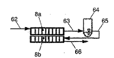
図4において、空調システム1に組み込まれ、閉じた、且つ完全な冷媒回路60を備えた図1の実施形態による空調システム1が示されている。冷媒回路は、R134a、R744、R1234yf又は他の冷媒用に設計されている。冷媒回路60は、蒸発器7と圧縮機61と凝縮器8とコレクタ64と膨張素子67とを備えている。
冷媒回路60の構成部品は、冷媒管路62、63、65、66、68、69によって接続されている。吸引管69は、蒸発器7を圧縮機61と接続し、圧力管路62は、圧縮機61を凝縮器8と接続する。冷媒は、圧力管路63を通って凝縮器8の第1区間からコレクタ64に流れる。圧力管路65及び66は、コレクタ64を凝縮器8の第2区間の入口と接続し、凝縮器8の第2区間の出口を膨張素子67と接続する。冷媒は、膨張素子67から冷媒管路68を通って蒸発器7に流れる。
圧縮機61は、電気的に駆動可能な圧縮機として形成されていることが好ましいが、変形例として、車両の内燃機関によって駆動されてもよい。膨張素子67は、制御可能な膨張素子、若しくは膨張弁として形成されていることが有利であるが、変形例として、感温膨張弁として形成されていてもよい。
In FIG. 4, the
The components of the
The
図4、図5a、及び図5bから、凝縮器8の種々の形態が明らかである。図4において、凝縮器8は、1つの構成部品として形成されている。冷媒は、冷媒管路62を通って凝縮器8の第1区間に流入し、第1区間からの流出後に冷媒管路63を通ってコレクタ64に誘導される。冷媒は、コレクタ64から出た後に冷媒管路65を通って、例えば冷媒を過冷却するために形成された凝縮器8の第2区間に流入する。冷媒管路66を介して、冷媒は膨張素子67へと流れる。
Various forms of the
図5a及び図5bによる実施形態では、凝縮器8は、2つの独立した構成部品8a、8bから構成されている。冷媒の流れ方向で構成部品8a、8b間には、液体分離器と一体化されたコレクタ64として形成された冷媒・相分離要素が配置されている。
In the embodiment according to FIGS. 5a and 5b, the
冷媒は、冷媒管路62を通って、冷媒の抜熱及び凝縮のために設けられた第1構成部品8aに流入し、第1構成部品8aから流出した後に冷媒管路63を通ってコレクタ64へと誘導される。冷媒は、コレクタ64から出た後に冷媒管路65を通り、冷媒を過冷却するために形成された第2構成部品8bに流入する。冷媒は、冷媒管路66を介して膨張素子67へと流れる。
The refrigerant flows into the
冷媒・相分離要素として、液体分離器と一体化されたコレクタ64を用いて、冷媒の流れ方向でコレクタ64の下流に配置された第2構成部品8bには液体冷媒しか供給されない。気相を分離することによって、構成部品8bをより小さい体積で、従ってより少ない所要スペースで形成することができる。冷媒のために必要な流断面は、液相中に蒸気分を含む2相冷媒が貫流する場合よりも小さい。
Using the
熱換器装置は、複数列で形成された凝縮面及び抜熱面と、付加的過冷却面とを有する。冷媒の抜熱及び凝縮のための構成部品8aは、少なくとも2列であるが、4列に形成されていることが好ましい。冷媒の過冷却のための構成部品8bは、少なくとも1列を有するが、2列を有することが好ましい。
The heat exchanger apparatus has a condensation surface and a heat removal surface formed in a plurality of rows, and an additional supercooling surface. The
図5aの熱交換器装置では、凝縮器8の構成部品8a、8bが空気質量流に対して直列に相前後して方向調整されており、空気質量流が連続的に貫流する。その場合、空気質量流は、構成部品8aの凝縮面及び抜熱面に当たり、続いて、構成部品8bの過冷却面を介して誘導される。
In the heat exchanger apparatus of FIG. 5a, the
図5bの熱交換器装置では、凝縮器8の構成部品8a、8bは、並列に相並べて方向調整されている。その場合、抜熱面及び凝縮面を有する構成部品8aは、第2フローチャネル4内に配置されていてもよいが、構成部品8bは、第1フローチャネル3内に配置されている。その場合、構成部品8a、8b若しくは凝縮面及び抜熱面、並びに過冷却面に、フローチャネル3、4内で空気質量流が平行に当たる。フローチャネル3を通って流れる予め冷却及び除湿された空気質量流は、空調システム1の再熱運転において、構成部品8bの過冷却面を流れる際に再び暖められる。
変形例として、構成部品8bは、空調システム1のハウジング2の外側に配置されていてもよく、その場合、走行中の風が供給される。
In the heat exchanger apparatus of FIG. 5b, the
As a modification, the
1 空調システム
2 ハウジング
3 第1フローチャネル
4 第2フローチャネル
5、6 ファン
7 熱交換器、蒸発器
8 熱交換器、凝縮器
8a、8b 凝縮器の構成部品
9 客室
10 仕切り壁
11、12 冷気流路
13 冷気流路の空気ガイド装置/フラップ
14 第1フローチャネルの流路
15 第1フローチャネルのバイパスチャネル
16、17 暖気流路
18 暖気流路の空気ガイド装置/フラップ
19 流路14への吸入用の空気ガイド装置
22 流路14からの吐出用の空気ガイド装置
23 冷気流路の冷気の空気ガイド装置/フラップ
24 バイパスチャネル用の空気ガイド装置/フラップ
25、26 暖気流路の空気ガイド装置/フラップ
27、27’ 第1フローチャネルと第2フローチャネル4の間で凝縮器に向かって流すための空気ガイド装置/フラップ
28、28’ 第1フローチャネル3と第2フローチャネル4との間で凝縮器から離れる場合の空気ガイド装置/フラップ
29、29’ 静的空気ガイド装置/空気ガイド板
30、30’ 静的空気ガイド装置/空気ガイド板
31、32 静的空気ガイド装置の面
33、34 空気ガイド装置の軸、回転軸
35、36 空気ガイド装置の回転方向
60 冷媒回路
61 圧縮機
62、63 冷媒管路、圧力管路
64 コレクタ
65、66、68 冷媒管路、圧力管路
67 膨張素子
69 冷媒管路、吸引管路
L 長さ
DESCRIPTION OF SYMBOLS 1 Air conditioning system 2 Housing 3 1st flow channel 4 2nd flow channel 5, 6 Fan 7 Heat exchanger, evaporator 8 Heat exchanger, condenser 8a, 8b Condenser component 9 Guest room 10 Partition wall 11, 12 Cooling Air flow channel 13 Air guide device / flap for cold flow channel 14 Flow channel for first flow channel 15 Bypass channel for first flow channel 16, 17 Warm air flow channel 18 Air guide device / flap for warm air flow channel 19 Air guide device for suction 22 Air guide device for discharge from passage 14 Air guide device / flap for cool air in cool air passage 24 Air guide device / flaps for bypass channel 25, 26 Air guide device for warm air passage / Flap 27, 27 'Empty for flowing between the first flow channel and the second flow channel 4 towards the condenser Guide device / flaps 28, 28 'Air guide device / flaps 29, 29' when leaving the condenser between the first flow channel 3 and the second flow channel 4 Static air guide device / air guide plate 30, 30 'Static air guide device / air guide plate 31, 32 Surface of static air guide device 33, 34 Shaft of air guide device, rotary shaft 35, 36 Rotation direction of air guide device 60 Refrigerant circuit 61 Compressor 62, 63 Refrigerant Pipe line, pressure line 64 Collector 65, 66, 68 Refrigerant line, pressure line 67 Expansion element 69 Refrigerant line, suction line L Length
Claims (4)
前記空調システム(1)は、空気を誘導するための第1フローチャネル(3)と第2フローチャネル(4)とを備えたハウジング(2)を有し、
冷媒回路(60)は、第1熱交換器(7)と圧縮機(61)と第2熱交換器(8)と膨張素子(67)とを有し、前記第1熱交換器(7)は、第1フローチャネル(3)のみに配置され、前記第2熱交換器(8)は、前記第2フローチャネル(4)に配置されており、
前記空調システム(1)は、前記客室(9)を冷却及び加熱する冷却設備運転及びヒートポンプ運転、並びに再熱運転のために形成されており、前記第2熱交換器(8)は、前記運転モードに関係なく凝縮器として形成され、且つ作動可能であり、
前記第2熱交換器(8)は、互いに分離して形成された2つの構成部品(8a、8b)を有し、
前記2つの構成部品(8a、8b)のうちの第1構成部品(8a)は、前記第2フローチャネル(4)に配置されていると共に、前記第1フローチャネル(3)に部分的に配置されており、凝縮面及び抜熱面を有し、
前記2つの構成部品(8a、8b)のうちの前記第2構成部品(8b)は、前記第2フローチャネル(4)のみに配置されており、過冷却面を有し、
前記第1構成部品(8a)と前記第2構成部品(8b)との間には、冷媒相分離要素が配置されており、
前記第2熱交換器(8)は、列で配置された管を有する管型熱交換器として形成されており、前記第1構成部品(8a)は、少なくとも2列に形成されており、前記第2構成部品(8b)は、少なくとも1列に形成され、
前記冷媒の凝縮の温度レベルよりも高い温度レベルへの空気の暖めが可能であり、
前記第1フローチャネル(3)は、流路(14)と、バイパスチャネル(15)と、を備え、前記流路(14)は、この流路(14)への吸入用の空気ガイド装置(19)と、前記流路(14)からの吐出用の空気ガイド装置(22)と、を備えており、前記バイパスチャネル(15)は、このバイパスチャネル(15)を通過する空気量を制御する空気ガイド装置(24)を備えており、
前記第1フローチャネル(3)に配置されている第1構成部品(8a)の一部は、前記流路(14)内に位置決めされているものであることを特徴とする空調システム。 An air conditioning system (1) that harmonizes the air in a passenger compartment (9) of a car equipped with a heat exchanger device,
The air conditioning system (1) has a housing (2) with a first flow channel (3) and a second flow channel (4) for guiding air,
The refrigerant circuit (60) includes a first heat exchanger (7), a compressor (61), a second heat exchanger (8), and an expansion element (67), and the first heat exchanger (7). Is arranged only in the first flow channel (3), the second heat exchanger (8) is arranged in the second flow channel (4),
The air conditioning system (1) is formed for a cooling facility operation and a heat pump operation for cooling and heating the cabin (9) and a reheating operation, and the second heat exchanger (8) is configured for the operation. Formed and operable as a condenser regardless of mode,
The second heat exchanger (8) has two components (8a, 8b) formed separately from each other,
The first component (8a) of the two components (8a, 8b) is disposed in the second flow channel (4) and partially disposed in the first flow channel (3). Has a condensing surface and a heat removal surface,
Of the two components (8a, 8b), the second component (8b) is disposed only in the second flow channel (4) and has a supercooling surface,
Wherein between the first component (8a) and said second component (8b), refrigerant phase separation element is disposed,
The second heat exchanger (8) is formed as a tubular heat exchanger having tubes arranged in rows, and the first component (8a) is formed in at least two rows, The second component (8b) is formed in at least one row,
Ri warmed can der of air into a higher temperature level than the temperature level of condensation of the refrigerant,
The first flow channel (3) includes a flow path (14) and a bypass channel (15), and the flow path (14) is an air guide device for suction into the flow path (14) ( 19) and an air guide device (22) for discharging from the flow path (14), and the bypass channel (15) controls the amount of air passing through the bypass channel (15). An air guide device (24),
Part of the first component (8a) disposed in the first flow channel (3) is positioned in the flow path (14), and the air conditioning system is characterized in that:
Applications Claiming Priority (2)
| Application Number | Priority Date | Filing Date | Title |
|---|---|---|---|
| DE102012108886.1 | 2012-09-20 | ||
| DE102012108886.1A DE102012108886B4 (en) | 2012-09-20 | 2012-09-20 | Heat exchanger arrangement and air conditioning system of a motor vehicle |
Related Child Applications (1)
| Application Number | Title | Priority Date | Filing Date |
|---|---|---|---|
| JP2016093413A Division JP2016166011A (en) | 2012-09-20 | 2016-05-06 | Heat exchanger apparatus and air conditioning system for motor vehicle |
Publications (2)
| Publication Number | Publication Date |
|---|---|
| JP2014061877A JP2014061877A (en) | 2014-04-10 |
| JP6231337B2 true JP6231337B2 (en) | 2017-11-15 |
Family
ID=50181559
Family Applications (2)
| Application Number | Title | Priority Date | Filing Date |
|---|---|---|---|
| JP2013195620A Active JP6231337B2 (en) | 2012-09-20 | 2013-09-20 | Automotive heat exchanger apparatus and air conditioning system |
| JP2016093413A Pending JP2016166011A (en) | 2012-09-20 | 2016-05-06 | Heat exchanger apparatus and air conditioning system for motor vehicle |
Family Applications After (1)
| Application Number | Title | Priority Date | Filing Date |
|---|---|---|---|
| JP2016093413A Pending JP2016166011A (en) | 2012-09-20 | 2016-05-06 | Heat exchanger apparatus and air conditioning system for motor vehicle |
Country Status (4)
| Country | Link |
|---|---|
| US (1) | US9242528B2 (en) |
| JP (2) | JP6231337B2 (en) |
| CN (1) | CN103673401B (en) |
| DE (1) | DE102012108886B4 (en) |
Families Citing this family (53)
| Publication number | Priority date | Publication date | Assignee | Title |
|---|---|---|---|---|
| US6889762B2 (en) | 2002-04-29 | 2005-05-10 | Bergstrom, Inc. | Vehicle air conditioning and heating system providing engine on and engine off operation |
| US9694651B2 (en) | 2002-04-29 | 2017-07-04 | Bergstrom, Inc. | Vehicle air conditioning and heating system providing engine on and off operation |
| US9346337B2 (en) * | 2011-02-24 | 2016-05-24 | Panasonic Intellectual Property Management Co., Ltd. | Air conditioning device for vehicle |
| GB2493741B (en) * | 2011-08-17 | 2017-02-22 | Gm Global Tech Operations Llc | Exhaust gas recirculation system for an internal combustion engine |
| JP2013159228A (en) * | 2012-02-06 | 2013-08-19 | Denso Corp | Vehicle air conditioner |
| US9796239B2 (en) * | 2013-03-13 | 2017-10-24 | Bergstrom Inc. | Air conditioning system utilizing heat recovery ventilation for fresh air supply and climate control |
| US9840130B2 (en) | 2013-03-13 | 2017-12-12 | Bergstrom Inc. | Air conditioning system utilizing thermal capacity from expansion of compressed fluid |
| JP6095777B2 (en) * | 2013-06-28 | 2017-03-15 | 三菱電機株式会社 | Air conditioner for vehicles |
| DE102013110965A1 (en) * | 2013-10-02 | 2015-04-16 | Halla Visteon Climate Control Corp. | Air conditioning system for a motor vehicle |
| US10245916B2 (en) | 2013-11-04 | 2019-04-02 | Bergstrom, Inc. | Low profile air conditioning system |
| FR3023346B1 (en) * | 2014-07-04 | 2016-08-26 | Valeo Systemes De Controle Moteur | ASSEMBLY FOR A THERMAL MOTOR AIR CIRCUIT |
| KR102250000B1 (en) * | 2015-04-29 | 2021-05-12 | 한온시스템 주식회사 | Heat pump system for vehicle |
| US10661632B2 (en) * | 2014-07-31 | 2020-05-26 | Hanon Systems | Heat pump system for vehicle |
| KR102326346B1 (en) * | 2015-04-29 | 2021-11-16 | 한온시스템 주식회사 | Heat pump system for vehicle |
| RU2564778C1 (en) | 2014-08-26 | 2015-10-10 | Самохвалов Сергей Андреевич | Landrover and its suspension |
| DE102014221143B4 (en) * | 2014-10-17 | 2016-09-29 | Mahle International Gmbh | Vehicle cooling system and associated operating method |
| DE102014116504A1 (en) * | 2014-11-12 | 2016-05-12 | Karlsruher Institut für Technologie | Device for generating climatic input conditions for air conditioning devices |
| KR101628530B1 (en) * | 2014-11-17 | 2016-06-09 | 현대자동차주식회사 | Air conditioner for vehicle |
| KR101628558B1 (en) | 2014-12-05 | 2016-06-09 | 현대자동차주식회사 | Air conditioner of vehicle |
| US9783024B2 (en) | 2015-03-09 | 2017-10-10 | Bergstrom Inc. | System and method for remotely managing climate control systems of a fleet of vehicles |
| DE102015207447B4 (en) | 2015-04-23 | 2023-12-07 | Airbus Operations Gmbh | Aircraft air conditioning system that can be controlled depending on the operating phase and method for operating such an aircraft air conditioning system |
| DE102015110571A1 (en) | 2015-07-01 | 2017-01-05 | Halla Visteon Climate Control Corporation | Vehicle air conditioning system and method for controlling the vehicle air conditioning system for temperature control of a vehicle battery |
| DE102015112030A1 (en) * | 2015-07-23 | 2017-01-26 | Halla Visteon Climate Control Corporation | Modular air conditioning system of a motor vehicle |
| KR101766045B1 (en) | 2015-10-08 | 2017-08-08 | 현대자동차주식회사 | Air conditioning system for vehicle |
| DE102015118221A1 (en) * | 2015-10-26 | 2017-04-27 | Hanon Systems | Refrigerant circuit for a vehicle air conditioner with heat pump function |
| CN106671728A (en) * | 2015-11-06 | 2017-05-17 | 福特环球技术公司 | Air conditioning system and control method thereof |
| KR101755926B1 (en) * | 2015-12-09 | 2017-07-10 | 현대자동차주식회사 | Air conditioning system for vehicle |
| US10006684B2 (en) | 2015-12-10 | 2018-06-26 | Bergstrom, Inc. | Air conditioning system for use in vehicle |
| US9874384B2 (en) | 2016-01-13 | 2018-01-23 | Bergstrom, Inc. | Refrigeration system with superheating, sub-cooling and refrigerant charge level control |
| JP6592466B2 (en) * | 2016-01-18 | 2019-10-16 | ハンオン システムズ | Air conditioning system for vehicles |
| CN105688612B (en) * | 2016-01-21 | 2017-12-01 | 云南科威液态金属谷研发有限公司 | A kind of liquid metal dehumidifier |
| US10589598B2 (en) | 2016-03-09 | 2020-03-17 | Bergstrom, Inc. | Integrated condenser and compressor system |
| FR3049237B1 (en) * | 2016-03-24 | 2019-04-19 | Valeo Systemes Thermiques | AIR CONDITIONING PACKAGE FOR A MOTOR VEHICLE AND AIR TREATMENT SYSTEM COMPRISING SUCH A HOUSING |
| FR3049238B1 (en) * | 2016-03-24 | 2019-04-19 | Valeo Systemes Thermiques | AIR CONDITIONING BOX FOR A MOTOR VEHICLE, SYSTEM AND METHOD FOR TREATING THE AIR COMPRISING SUCH A BOX |
| KR101822287B1 (en) * | 2016-07-04 | 2018-01-26 | 현대자동차주식회사 | Air conditioning system for vehicle |
| KR101822288B1 (en) * | 2016-07-06 | 2018-01-26 | 현대자동차주식회사 | Air conditioning apparatus for vehicle |
| US10081226B2 (en) | 2016-08-22 | 2018-09-25 | Bergstrom Inc. | Parallel compressors climate system |
| US10562372B2 (en) | 2016-09-02 | 2020-02-18 | Bergstrom, Inc. | Systems and methods for starting-up a vehicular air-conditioning system |
| US10675948B2 (en) | 2016-09-29 | 2020-06-09 | Bergstrom, Inc. | Systems and methods for controlling a vehicle HVAC system |
| US10724772B2 (en) | 2016-09-30 | 2020-07-28 | Bergstrom, Inc. | Refrigerant liquid-gas separator having an integrated check valve |
| US10369863B2 (en) | 2016-09-30 | 2019-08-06 | Bergstrom, Inc. | Refrigerant liquid-gas separator with electronics cooling |
| DE102017103633A1 (en) * | 2017-02-22 | 2018-04-05 | Miele & Cie. Kg | heat pump |
| US11448441B2 (en) | 2017-07-27 | 2022-09-20 | Bergstrom, Inc. | Refrigerant system for cooling electronics |
| CN109720163A (en) * | 2017-10-31 | 2019-05-07 | 上汽通用汽车有限公司 | Automotive air-conditioning system |
| DE102018124748B4 (en) * | 2017-11-24 | 2023-02-09 | Hanon Systems | Multi-zone air conditioning for vehicles |
| US11420496B2 (en) | 2018-04-02 | 2022-08-23 | Bergstrom, Inc. | Integrated vehicular system for conditioning air and heating water |
| DE102018005338A1 (en) | 2018-07-06 | 2020-01-09 | Truma Gerätetechnik GmbH & Co. KG | air conditioning |
| JP2020019352A (en) * | 2018-07-31 | 2020-02-06 | サンデンホールディングス株式会社 | Vehicular air conditioner |
| KR102661622B1 (en) * | 2018-11-12 | 2024-04-29 | 현대자동차주식회사 | Air conditioning unit for vehicle |
| DE102019125649A1 (en) * | 2019-09-24 | 2021-03-25 | Audi Ag | Air conditioning method |
| US11867424B1 (en) * | 2020-03-05 | 2024-01-09 | Apple Inc. | Thermal control system |
| US11642933B2 (en) * | 2020-06-24 | 2023-05-09 | Honda Motor Co., Ltd. | Heat transfer system for a vehicle |
| DE102021206802B3 (en) * | 2021-06-30 | 2022-07-28 | Siemens Mobility GmbH | Air conditioning arrangement for an interior of a vehicle |
Family Cites Families (62)
| Publication number | Priority date | Publication date | Assignee | Title |
|---|---|---|---|---|
| US6430951B1 (en) * | 1991-04-26 | 2002-08-13 | Denso Corporation | Automotive airconditioner having condenser and evaporator provided within air duct |
| JP2568272Y2 (en) * | 1993-03-25 | 1998-04-08 | 株式会社ゼクセル | Automotive air conditioning controller |
| FR2743027B1 (en) | 1995-12-29 | 1998-01-23 | Renault | AIR CONDITIONING DEVICE FOR THE VEHICLE INTERIOR |
| JPH10329535A (en) * | 1997-05-28 | 1998-12-15 | Calsonic Corp | Air conditioner for automobile |
| DE69721268T2 (en) * | 1997-10-31 | 2004-01-29 | Calsonic Kansei Corp | Vehicle air conditioning |
| JP3985384B2 (en) * | 1998-09-24 | 2007-10-03 | 株式会社デンソー | Refrigeration cycle equipment |
| JP3879296B2 (en) * | 1999-01-19 | 2007-02-07 | 株式会社デンソー | Heat exchanger |
| JP2002225535A (en) * | 2001-01-31 | 2002-08-14 | Calsonic Kansei Corp | Air-conditioning system for vehicle and air conditioning unit for vehicle |
| KR100723974B1 (en) * | 2001-03-27 | 2007-06-04 | 한라공조주식회사 | Air conditioner for vehicles |
| US7654100B2 (en) * | 2001-04-26 | 2010-02-02 | Rini Technologies, Inc. | Method and apparatus for high heat flux heat transfer |
| KR100872468B1 (en) * | 2002-05-24 | 2008-12-08 | 한라공조주식회사 | Multistage gas and liquid phase separation type condenser |
| JP2004136851A (en) * | 2002-10-21 | 2004-05-13 | Denso Corp | Air conditioner for vehicle |
| KR100528392B1 (en) * | 2003-01-27 | 2005-11-15 | 가부시키가이샤 덴소 | Vapor-compression refrigerant cycle system with refrigeration cycle and rankine cycle |
| ATE439994T1 (en) | 2003-07-09 | 2009-09-15 | Behr Gmbh & Co Kg | INSTALLATION ARRANGEMENT FOR AN AIR CONDITIONING SYSTEM WITH HEATER |
| US6862892B1 (en) | 2003-08-19 | 2005-03-08 | Visteon Global Technologies, Inc. | Heat pump and air conditioning system for a vehicle |
| DE10346827B4 (en) | 2003-10-06 | 2017-07-13 | Mahle International Gmbh | Method for regulating the air temperature of a motor vehicle air conditioning system with auxiliary heating function |
| JP4321242B2 (en) * | 2003-12-02 | 2009-08-26 | 株式会社デンソー | Air conditioner for vehicles |
| DE102004003787A1 (en) | 2004-01-23 | 2005-08-11 | Behr Gmbh & Co. Kg | Air conditioner for cooling engine of motor vehicle, has two heat exchangers serving as evaporator and condenser, respectively, and designed as single combined heat exchanger with common cooling agent circuit |
| US7178353B2 (en) * | 2004-02-19 | 2007-02-20 | Advanced Thermal Sciences Corp. | Thermal control system and method |
| DE102004011608A1 (en) * | 2004-03-18 | 2005-10-13 | Obrist Engineering Gmbh | Heat exchanger of a vehicle air conditioning system |
| DE102005032277B4 (en) * | 2004-07-12 | 2019-08-14 | Denso Corporation | Vapor compression refrigeration unit |
| JP4484636B2 (en) * | 2004-09-02 | 2010-06-16 | サンデン株式会社 | Air conditioner |
| US7111469B2 (en) * | 2004-09-22 | 2006-09-26 | Horan Christopher J | Process for refrigerant charge level detection using a neural net |
| JP4654655B2 (en) | 2004-10-19 | 2011-03-23 | 株式会社デンソー | Vapor compression refrigerator |
| JP4614441B2 (en) * | 2005-06-10 | 2011-01-19 | 日立アプライアンス株式会社 | Scroll compressor |
| US7628027B2 (en) * | 2005-07-19 | 2009-12-08 | Hussmann Corporation | Refrigeration system with mechanical subcooling |
| JP4631576B2 (en) | 2005-07-21 | 2011-02-16 | 株式会社デンソー | Heating cycle device, its control device and its control method |
| JP2007322021A (en) | 2006-05-30 | 2007-12-13 | Denso Corp | Refrigerating cycle device for vehicle |
| DE102007007233A1 (en) * | 2007-02-14 | 2008-09-25 | Behr Gmbh & Co. Kg | Motor vehicle i.e. car, has heat exchanger e.g. gas cooler, installed such that air inlet speed profile of air flow, which is passed through or against heat exchanger, is inhomogeneously formed |
| US7637031B2 (en) | 2007-06-26 | 2009-12-29 | Gm Global Technology Operations, Inc. | Evaporator core drying system |
| JP2009023564A (en) * | 2007-07-20 | 2009-02-05 | Denso Corp | Air conditioner for vehicle |
| JP2009184493A (en) | 2008-02-06 | 2009-08-20 | Calsonic Kansei Corp | Air conditioning system for vehicle |
| JP2009190579A (en) | 2008-02-14 | 2009-08-27 | Calsonic Kansei Corp | Air conditioning system |
| JP2009190687A (en) | 2008-02-18 | 2009-08-27 | Calsonic Kansei Corp | Air conditioning system for vehicle |
| JP4557031B2 (en) | 2008-03-27 | 2010-10-06 | 株式会社デンソー | Air conditioner for vehicles |
| DE102008028178A1 (en) | 2008-05-30 | 2009-12-03 | Konvekta Ag | Air conditioner for conditioning a plurality of fluids |
| CN101464077A (en) * | 2009-01-09 | 2009-06-24 | 广东美的电器股份有限公司 | Finned tube heat exchanger of air conditioner |
| DE102010024853B4 (en) | 2009-06-26 | 2019-05-16 | Denso Corporation | Air conditioning for vehicle |
| DE102010025779A1 (en) | 2009-07-03 | 2011-01-13 | DENSO CORPORATION, Kariya-shi | Air conditioning system for implementation of pre-air conditioning in passenger compartment of hybrid auto, during parking of vehicle, has control acting so that blower has predetermined efficiency level related to heat source |
| JP5663849B2 (en) | 2009-07-09 | 2015-02-04 | 株式会社デンソー | Air conditioner for vehicles |
| JP5459060B2 (en) | 2009-07-10 | 2014-04-02 | 株式会社デンソー | Air conditioner for vehicles |
| EP2463131B1 (en) | 2009-08-07 | 2013-11-13 | Mitsubishi Heavy Industries, Ltd. | Vehicle air conditioning system |
| DE102009028522B4 (en) | 2009-08-13 | 2017-05-11 | Hanon Systems | Compact air conditioning system for a motor vehicle |
| JP2011140291A (en) | 2010-01-11 | 2011-07-21 | Denso Corp | Air conditioner for vehicle |
| WO2011087001A1 (en) | 2010-01-12 | 2011-07-21 | 本田技研工業株式会社 | Air conditioning system for vehicle |
| JP5021773B2 (en) | 2010-01-13 | 2012-09-12 | 本田技研工業株式会社 | Vehicle air conditioning system |
| EP2524829B1 (en) | 2010-01-15 | 2017-09-13 | Mitsubishi Heavy Industries, Ltd. | Vehicle air-conditioning system and driving control method therefor |
| JP5423528B2 (en) | 2010-03-29 | 2014-02-19 | 株式会社日本自動車部品総合研究所 | Heat pump cycle |
| EP2554413B1 (en) | 2010-03-31 | 2014-03-12 | Honda Motor Co., Ltd. | Heat pump air conditioning system for vehicle |
| JP5717474B2 (en) * | 2010-04-16 | 2015-05-13 | 株式会社ケーヒン・サーマル・テクノロジー | Capacitor |
| JP5533207B2 (en) | 2010-05-06 | 2014-06-25 | 株式会社日本自動車部品総合研究所 | Heat pump cycle |
| JP5488185B2 (en) | 2010-05-10 | 2014-05-14 | 株式会社デンソー | Air conditioner for vehicles |
| DE102010038406A1 (en) | 2010-07-26 | 2012-01-26 | Behr Gmbh & Co. Kg | System for e.g. warming up and/or cooling inner space of hybrid motor car, has vaporizer coupled with refrigerant circuit, where heat removed from heat exchanger is recovered due to hydraulic connection between heat exchanger and vaporizer |
| DE102011109055A1 (en) | 2010-09-04 | 2012-03-08 | Volkswagen Ag | Aircondition for a vehicle and method for air conditioning a vehicle |
| FR2965516B1 (en) | 2010-10-04 | 2016-05-06 | Renault Sa | DEVICE FOR THERMALLY CONTROLLING THE INTERIOR OF A MOTOR VEHICLE |
| DE102010043000A1 (en) | 2010-10-27 | 2012-05-03 | Behr Gmbh & Co. Kg | Automotive air conditioning system |
| DE102010049871A1 (en) | 2010-10-28 | 2012-05-03 | Robert Bosch Gmbh | Heat pump device with de-icing function |
| CN102958724B (en) | 2010-11-01 | 2015-06-24 | 三菱重工业株式会社 | Heat-pump vehicular air conditioner and defrosting method thereof |
| DE102010051471A1 (en) * | 2010-11-15 | 2012-05-16 | Audi Ag | Vehicle with air conditioning |
| DE102010056283A1 (en) | 2010-12-24 | 2012-06-28 | Volkswagen Ag | Heat transfer system, particularly for motor vehicle, has refrigerant circuit formed as heat pump cycle, which has compressor and heat exchanger |
| JP5799792B2 (en) * | 2011-01-07 | 2015-10-28 | 株式会社デンソー | Refrigerant radiator |
| US10160291B2 (en) | 2011-01-21 | 2018-12-25 | Sanden Holdings Corporation | Vehicle air conditioning apparatus |
-
2012
- 2012-09-20 DE DE102012108886.1A patent/DE102012108886B4/en active Active
-
2013
- 2013-09-20 JP JP2013195620A patent/JP6231337B2/en active Active
- 2013-09-20 US US14/032,976 patent/US9242528B2/en active Active
- 2013-09-22 CN CN201310432537.0A patent/CN103673401B/en active Active
-
2016
- 2016-05-06 JP JP2016093413A patent/JP2016166011A/en active Pending
Also Published As
| Publication number | Publication date |
|---|---|
| CN103673401A (en) | 2014-03-26 |
| CN103673401B (en) | 2018-05-08 |
| DE102012108886B4 (en) | 2019-02-14 |
| US9242528B2 (en) | 2016-01-26 |
| DE102012108886A1 (en) | 2014-03-20 |
| US20140075973A1 (en) | 2014-03-20 |
| JP2014061877A (en) | 2014-04-10 |
| JP2016166011A (en) | 2016-09-15 |
Similar Documents
| Publication | Publication Date | Title |
|---|---|---|
| JP6231337B2 (en) | Automotive heat exchanger apparatus and air conditioning system | |
| JP6125565B2 (en) | Automotive air conditioning system | |
| JP5951571B2 (en) | Heat transfer medium device and air conditioning system for heat absorption of automobile | |
| JP6751457B2 (en) | Automotive air conditioning system and method of operating the same | |
| JP7243410B2 (en) | Vehicle battery heating device | |
| KR102005418B1 (en) | Air-conditioning system for conditioning the air of a passenger compartment of a motor vehicle and air guiding arrangement for selectively supplying air mass flows in the air-conditioning system | |
| JP5342520B2 (en) | Compact temperature control system for automobiles | |
| EP2497662B1 (en) | Heat pump system for vehicle | |
| US9821627B2 (en) | Air-conditioning system for a motor vehicle | |
| US20140060102A1 (en) | Mild ambient vehicular heat pump system | |
| KR102266483B1 (en) | Heat exchanger arrangement for an air conditioning system and air conditioning system of a motor vehicle and method for operating the air conditioning system | |
| WO2014156585A1 (en) | Air-conditioning device for vehicle | |
| JP2009257748A (en) | Heating and air-conditioning unit for automobile | |
| CN102692100A (en) | Heat exchange system and vehicle refrigeration cycle system | |
| JP2021147044A (en) | System for air-conditioning air in vehicle interior and transferring heat through drive component of motor vehicle, and method for operating the system | |
| CN116194313A (en) | Steam injection module and heat pump system using the same | |
| US10449834B2 (en) | Refrigerant circuit for a vehicle air conditioning system with heat pump | |
| KR102456814B1 (en) | Air conditioning system for vehicle | |
| JP2020003171A (en) | Heat exchanger and vehicle air conditioner | |
| CN217863620U (en) | Distributed air conditioning assembly, vehicle and indirect heat pump air conditioning system | |
| KR20160014830A (en) | Air conditioner for vehicle | |
| WO2020003968A1 (en) | Heat exchanger and vehicular air-conditioning device | |
| WO2020129496A1 (en) | Condenser and air conditioning device for vehicle | |
| WO2020129497A1 (en) | Condenser and air conditioning device for vehicle | |
| JP2015196475A (en) | Vehicle air conditioner |
Legal Events
| Date | Code | Title | Description |
|---|---|---|---|
| A711 | Notification of change in applicant |
Free format text: JAPANESE INTERMEDIATE CODE: A711 Effective date: 20140508 |
|
| A977 | Report on retrieval |
Free format text: JAPANESE INTERMEDIATE CODE: A971007 Effective date: 20141118 |
|
| A131 | Notification of reasons for refusal |
Free format text: JAPANESE INTERMEDIATE CODE: A131 Effective date: 20141208 |
|
| A601 | Written request for extension of time |
Free format text: JAPANESE INTERMEDIATE CODE: A601 Effective date: 20150309 |
|
| A521 | Request for written amendment filed |
Free format text: JAPANESE INTERMEDIATE CODE: A523 Effective date: 20150608 |
|
| A02 | Decision of refusal |
Free format text: JAPANESE INTERMEDIATE CODE: A02 Effective date: 20160104 |
|
| A521 | Request for written amendment filed |
Free format text: JAPANESE INTERMEDIATE CODE: A523 Effective date: 20160506 |
|
| A911 | Transfer to examiner for re-examination before appeal (zenchi) |
Free format text: JAPANESE INTERMEDIATE CODE: A911 Effective date: 20160627 |
|
| A912 | Re-examination (zenchi) completed and case transferred to appeal board |
Free format text: JAPANESE INTERMEDIATE CODE: A912 Effective date: 20160902 |
|
| RD04 | Notification of resignation of power of attorney |
Free format text: JAPANESE INTERMEDIATE CODE: A7424 Effective date: 20170413 |
|
| A521 | Request for written amendment filed |
Free format text: JAPANESE INTERMEDIATE CODE: A523 Effective date: 20170620 |
|
| A61 | First payment of annual fees (during grant procedure) |
Free format text: JAPANESE INTERMEDIATE CODE: A61 Effective date: 20171019 |
|
| R150 | Certificate of patent or registration of utility model |
Ref document number: 6231337 Country of ref document: JP Free format text: JAPANESE INTERMEDIATE CODE: R150 |
|
| R250 | Receipt of annual fees |
Free format text: JAPANESE INTERMEDIATE CODE: R250 |
|
| R250 | Receipt of annual fees |
Free format text: JAPANESE INTERMEDIATE CODE: R250 |
|
| R250 | Receipt of annual fees |
Free format text: JAPANESE INTERMEDIATE CODE: R250 |
|
| R250 | Receipt of annual fees |
Free format text: JAPANESE INTERMEDIATE CODE: R250 |